Eective: 06-21-24
Replaces: 04-15-24
P/N: 100-10000111 Rev. 08
This manual should be maintained in legible condition and kept adjacent to the heater or in a safe place for future
reference.
WARNING: If the information is not followed exactly, a re or explosion may result causing property
damage, personal injury or death.
— Do not store or use gasoline or other flammable vapors and liquids or other combustible materials
in the vicinity of this or any other appliance. To do so may result in an explosion or fire.
— WHAT TO DO IF YOU SMELL GAS
• Do not try to light any appliance.
• Do not touch any electrical switch; do not use any phone in your building.
• Immediately call your gas supplier from a neighbor’s phone. Follow the gas supplier’s instructions.
• If you cannot reach your gas supplier, call the fire department.
— Installation and service must be performed by a qualified installer, service agency or the gas supplier.
Gas-Fired Pool
and Spa Heater
Models: 264 and 404
SCAN WITH QR EQUIPPED SMART
DEVICE FOR ONLINE MANUAL.
NOTICE
INSTALLATION & OPERATION MANUAL
HEAT EXCHANGER TECHNOLOGY
™

2
INSTALLATION & OPERATION MANUAL
QUICK REFERENCE GUIDE
CLEARANCES
Space required: See pages 7-9.
Minimum and service clearances: See page 7 for
clearances table. Note that local codes prevail.
PIPING
Pressure relief valve: See page 21 for
recommended PRV orientation.
Flow rates: See page 19.
GAS
Distance to regulator (pipe lengths) and gas inlet
sizes: See page 19.
Required pressure for Natural Gas:
Min = 3.5" WC (Dynamic), Max = 10.5" WC (Static)
Required pressure for Propane Gas:
Min = 8.0" WC (Dynamic), Max = 13" WC (Static)
Sediment trap is required for all installations:
See page 18.
WATER CHEMISTRY
Water chemistry requirements: See page 5.
POWER
Supply voltage: See page 24 for acceptable input
voltages.
VENTING
Materials: See pages 13, 15 and 16.
CONTROLS INTERFACE
Controls Wiring diagram: See page 26.
User interface: See page 27.
Remote operation: See page 36.
Revision 8 reflects the following changes: Updated Figure 9 to display a larger venting diameter. Added minimum and
maximum venting code details to "Vertical Venting" section. Updated minor verbiage in the "Program Menu" section. Updated
Tables P & Q. Added "Note" to "Control Logic" Flow Chart. Added "Caution" below Figure 146. Added additional bullet points to
"Note" above Figure 147. Renamed IPL item 6-M and 10-M to replace the word "Bezel" with "Display Assembly".
A
AVERTISSEMENT: Assurez-vous de bien
suivre les instructions données dans cette notice
pour réduire au minimum le risque d’incendie ou
d’explosion ou pour éviter tout dommage matériel,
toute blessure ou la mort.
Ne pas entreposer ni utiliser d’essence ou ni d’autres
vapeurs ou liquides inammables à proximité de cet
appareil ou de tout autre appareil.
QUE FAIRE SI VOUS SENTEZ UNE ODEUR DE
GAZ:
• Ne pas tenter d’allumer d’appareil.
• Ne touchez á aucun interrupteur; ne pas vous
servir des téléphones se trouvant dans la
bâtiment.
• Appelez immédiatement votre fournisseur de
gaz depuis un voisin. Suivre les instructions du
fournisseur.
• Si vous ne pouvez rejoindere le fournisseur,
appelez le service es incendies.
L’installation et l’entretien doivent être assurés par
un installeur qualié ou par le fournisseur de gaz.

3
INSTALLATION & OPERATION MANUAL
TABLE OF CONTENTS
1. WARNINGS ............................................................. 4
Pay Attention to These Terms ................................. 4
General Safety ........................................................5
2. WATER CHEMISTRY ............................................. 5
Automatic Chlorinators and Chemical Feeders.......5
3. BEFORE INSTALLATION ...................................... 6
Receiving equipment...............................................6
Rating and certications ..........................................6
Elevation ................................................................. 6
Required Power Supply .......................................... 6
Ambient Temperature Rating ..................................6
4. INSTALLATION ....................................................... 6
Installation Codes ...................................................7
Clearances ..............................................................7
Outdoor Heater Installation .....................................7
Combustion and Ventilation Air ............................. 10
Direct Vent and Ducted Combustion Air Systems..10
Venting .................................................................. 13
Gas Supply Connections.......................................18
Gas Regulator Best Practices ...............................19
Flow Rates ............................................................19
ProTek Shield Assembly........................................ 20
Unitherm Governor Operation ...............................20
Internal Automatic Bypass Valve ...........................21
External Auxiliary Bypass Valve ............................ 21
Auxiliary Bypass Valve Adjustment ....................... 21
Pressure Relief Valve Installation .......................... 21
Plumbing Diagrams ...............................................23
Water/Flue Connection Reversal .......................... 24
5. ELECTRICAL WIRING ......................................... 24
Electrical Power Draw ...........................................24
Transformer Wiring ...............................................25
6. CONTROLS WIRING DIAGRAM ........................ 26
7. CONTROLS ........................................................... 27
Heater Top Removal .............................................27
Control Adjustments ............................................. 27
Operation .............................................................. 28
Service Menus ...................................................... 28
Program Menu ...................................................... 31
Control Lockout .....................................................34
Status and Diagnostics ......................................... 34
Remote Mode Selector - Installation
and Operation........................................................36
Time Clock/Fireman’s Switch ................................38
8. OPERATING INSTRUCTIONS ............................ 44
Before Start-Up .....................................................44
Start-Up Procedures ............................................. 44
9. MAINTENANCE AND CARE ............................... 47
Cold Weather Operation ....................................... 47
10. TROUBLESHOOTING ......................................... 48
Operation and Troubleshooting - Flow Chart ........ 49
Control Logic - Flow Chart .................................... 50
11. CONNECT TO WI-FI WITH RAYMOTE .............. 51
Preparing the Unit for Connection .........................52
Add a New Heater to Raymote ............................. 52
For iPhone 6 and Earlier Versions ........................ 56
AVIA Heater Setup ................................................58
12. RAYMOTE MOBILE APP ..................................... 58
User and Organization Settings ............................58
Help and Tech Support .........................................61
Main View ..............................................................62
Automation ............................................................63
Pool-Spa Mode Screen .........................................65
Accessories Screen .............................................. 67
Reset Wi-Fi Credentials ........................................68
Reconnect to Wi-Fi................................................68
Add a New User to your Organization...................73
Client Accounts: Invite a Contractor ...................... 75
Partner Accounts: Invite New Clients .................... 77
Switch to other Organizations ...............................79
Connectivity Troubleshooting ................................ 80
13. AUXILIARY CONTROL OUTPUT ...................... 81
14. REPLACEMENT PARTS ..................................... 83
15. ILLUSTRATED PARTS LIST .............................. 84
16. IMPORTANT INSTRUCTIONS FOR THE
COMMONWEALTH OF MASSACHUSETTS ... 93
17. QR CODES ............................................................ 94
THIS INSTALLATION MANUAL MAY NOT BE THE LATEST REVISION PRINTED AT THE TIME OF PRODUCT SHIPMENT. VISIT THE RAYPAK
WEBSITE TO VERIFY THE MANUAL DELIVERED WITH YOUR RAYPAK UNIT IS THE MOST UP-TO-DATE VERSION; OR SCAN THE QR CODE
ON THE COVER PAGE.
4
INSTALLATION & OPERATION MANUAL
A
WARNING: Gasoline, as well as other ammable
materials and liquids (adhesives, solvents, etc.), and
the vapors they produce, are extremely dangerous. Do
not handle, use, or store gasoline or other ammable or
combustible materials in the vicinity of a heater.
A
WARNING: Improper installation, adjustment,
alteration, service, or maintenance can cause property
damage, personal injury or loss of life. Installation
and service must be performed by a qualied installer,
service agency, or the gas supplier.
A
WARNING: Do not install within 3 feet (0.9 m) of
a heat pump or an outdoor condensing unit. Strong
air intake from this type of equipment can disturb the
combustion process and cause damage or personal
injury.
A
WARNING: UL-recognized fuel gas detectors are
recommended in all enclosed propane and natural
gas applications wherein there is a potential for an
explosive mixture of fuel gas to accumulate and their
installation should be in accordance with the detector
manufacturer’s recommendations and/or local laws,
rules, regulations, or customs.
A
WARNING: The heater shall not be located in an
area where water sprinklers, or other devices, may cause
water to spray through the cabinet louvers and into the
heater. This could cause internal rusting or damage
electrical components, causing damage which will not
be covered under warranty.
1. WARNINGS
Pay Attention to These Terms
A
DANGER
Indicates the presence of immediate hazards which will cause severe personal injury, death or
substantial property damage if ignored.
A
WARNING
Indicates the presence of hazards or unsafe practices which could cause severe personal injury,
death or substantial property damage if ignored.
A
CAUTION
Indicates the presence of hazards or unsafe practices which could cause minor personal injury
or product or property damage if ignored.
CAUTION
CAUTION used without the warning alert symbol indicates a potentially hazardous condition
which could cause minor personal injury or product or property damage if ignored.
NOTE
Indicates special instructions on installation, operation, or maintenance which are important but
not related to personal injury hazards.
A
WARNING: Both natural gas and propane have
an odorant added to aid in detecting a gas leak. Some
people may not physically be able to smell or recognize
this odorant. If you are unsure or unfamiliar with the
smell of natural gas or propane, ask your local gas
supplier. Other conditions, such as “odorant fade,”
which causes the odorant to diminish in intensity, can
also hide, camouage, or otherwise make detecting a
gas leak by smell more dicult.
A
WARNING: To minimize the possibility of improper
operation, serious personal injury, re, or damage to the
heater:
• Always keep the area around the heater free of
combustible materials, gasoline, and other ammable
liquids and vapors.
• Heater should never be covered or have any blockage
to the ow of fresh air to the heater.
A
WARNING: This unit contains refractory ceramic
ber (RCF) insulation in the combustion chamber. RCF,
as manufactured, does not contain respirable crystalline
silica. However, following sustained exposure to very
high temperatures [greater than 2192°F (1200°C), the
RCF can transform into crystalline silica (cristabolite).
The International Agency for Research on Cancer
(IARC) has classied the inhalation of crystalline silica
(cristabolite) as carcinogenic to humans.
When removing the burner or heat exchanger, take
precautions to avoid creating airborne dust and avoid
inhaling airborne bers. When cleaning spills, use wet
sweeping or High Eciency Particulate Air (HEPA)
ltered vacuum to minimize airborne dust. Use feasible
engineering controls such as local exhaust ventilation
or dust collecting systems to minimize airborne dust.
Wear appropriate personal protective equipment
including gloves, safety glasses with side shields, and
appropriate NIOSH-certied respiratory protection,
to avoid inhalation of airborne dust and airborne ber
particles.
5
INSTALLATION & OPERATION MANUAL
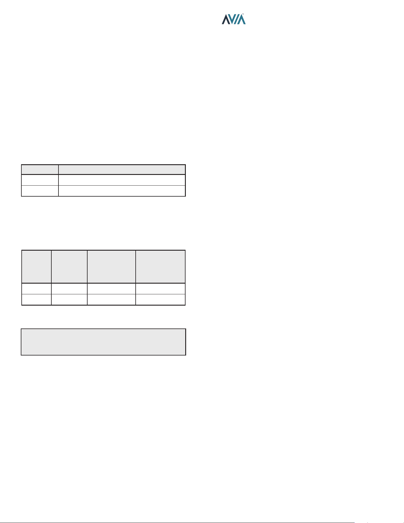
Recommended Level(s) Fiberglass Pools Fiberglass Spas Other Pool and Spa Types
Water Temperature 68-88°F (20-31°C) 89-104°F (31-40°C) 68-104°F (20-40°C)
pH 7.3-7.4 7.3-7.4 7.6-7.8
Total Alkalinity (ppm) 120-150 120-150 80-120
Calcium Hardness (ppm) 200-300 150-200 200-400
Salt (ppm) 4500 Maximum 4500 Maximum 4500 Maximum
Free Chlorine (ppm)* 2-3 2-3 2-3
Total Dissolved Solids (ppm) 3000 Maximum** 3000 Maximum** 3000 Maximum**
*Free Chlorine MUST NOT EXCEED 5 ppm!
**In saltwater chlorinated pools, the Total Dissolved Solids (TDS) can be as high as 6000 ppm.
Table A. Pool Water Chemistry
General Safety
Elevated water temperature can be hazardous. The
U.S. Consumer Product Safety Commission has these
guidelines:
1. Spa water temperatures should never exceed 104°F
(40°C). A temperature of 100°F (38°C) is considered
safe for a healthy adult. Special caution is suggested
for young children.
2. Drinking of alcoholic beverages before or during spa
or hot tub use can cause drowsiness which could
lead to unconsciousness and subsequently result in
drowning.
3. Pregnant Women Beware! Soaking in water over
102°F (39°C) can cause fetal damage during the first
three months of pregnancy resulting in the birth of a
brain-damaged or deformed child. Pregnant women
should stick to the 100°F (38°C) maximum rule.
4. Before entering the spa or hot tub, users should check
the water temperature with an accurate thermometer;
spa or hot tub thermostats may err in regulating water
temperatures by as much as 4°F (2.2°C).
5. Persons with a medical history of heart disease,
circulatory problems, diabetes, or blood pressure
problems should obtain a physician’s advice before
using spas or hot tubs.
6. Persons taking medications which induce
drowsiness, such as tranquilizers, antihistamines, or
anticoagulants, should not use spas or hot tubs.
2. WATER CHEMISTRY
NOTE: Corrosive water voids all warranties.
Chemical imbalance can cause severe damage to your
heater and associated equipment. Maintain your water
chemistry according to Table A. If the mineral content
and dissolved solids in the water become too high, scale
forms inside the heat exchanger tubes, reducing heater
eciency and damaging the heater. If the pH drops below
7.2, this will cause corrosion of the heat exchanger and
severely damage the heater. Heat exchanger damage
resulting from chemical imbalance is not covered by
the warranty.
For your health and the protection of your pool equipment,
it is essential that your water be chemically balanced. The
following levels must be used as a guide for balanced
water.
A
CAUTION: Free chlorine must not exceed 5 ppm
which can damage the heater and is not covered under
warranty.
• Occasional chemical shock dosing of the pool or spa
water should not damage the heater providing the
water is balanced.
• Automatic chemical dosing devices and salt
chlorinators are usually more efficient in heated
water, unless controlled, they can lead to excessive
chlorine level which can damage your heater.
• Check valve should be installed between the heater
outlet and a chlorinator or other chemical dosing
device.
• Further advice should be obtained from your pool
or spa builder, accredited pool shop, or chemical
supplier for the correct levels for your water.
Automatic Chlorinators
and Chemical Feeders
All chemicals must be introduced and completely diluted
into the pool or spa water before being circulated through
the heater. Do not place sanitizing chemicals in the
skimmer. High chemical concentrations will result when
the pump is not running (e.g. overnight).
Chlorinators must feed downstream of the heater and have
an anti-siphoning device/check valve to prevent chemical
backup into the heater when the pump is shut o. See
"Plumbing Diagram" on page 23.
NOTE: High chemical concentrates from feeders and
chlorinators that are out of adjustment will cause rapid
corrosion to the heat exchanger. Such damage is not
covered under the warranty.
6
INSTALLATION & OPERATION MANUAL
3. BEFORE INSTALLATION
Receiving Equipment
The manufacturer recommends that this manual be
reviewed thoroughly before installing the pool/spa heater. If
there are any questions that this manual does not answer,
please contact the factory or your local representative.
On receipt of your equipment it is suggested that you
visually check for external damage to the carton. If the
carton is damaged, a note should be made on the Bill
of Lading when signing for the equipment. Remove the
heater from the carton. If it is damaged, report the damage
to the carrier immediately. Save the carton.
These items are shipped inside a box in the carton with
the heater:
Standard Unit
1. (2) 2" CPVC Tailpiece
2. (2) 2" CPVC Ring Nut
3. (2) O-rings
4. (1) 120V Blower Adapter
5. (1) 3-Wire Remote Harness
6. (1) Auxiliary Harness / Terminal
7. (1) Raymote Quick Start Guide
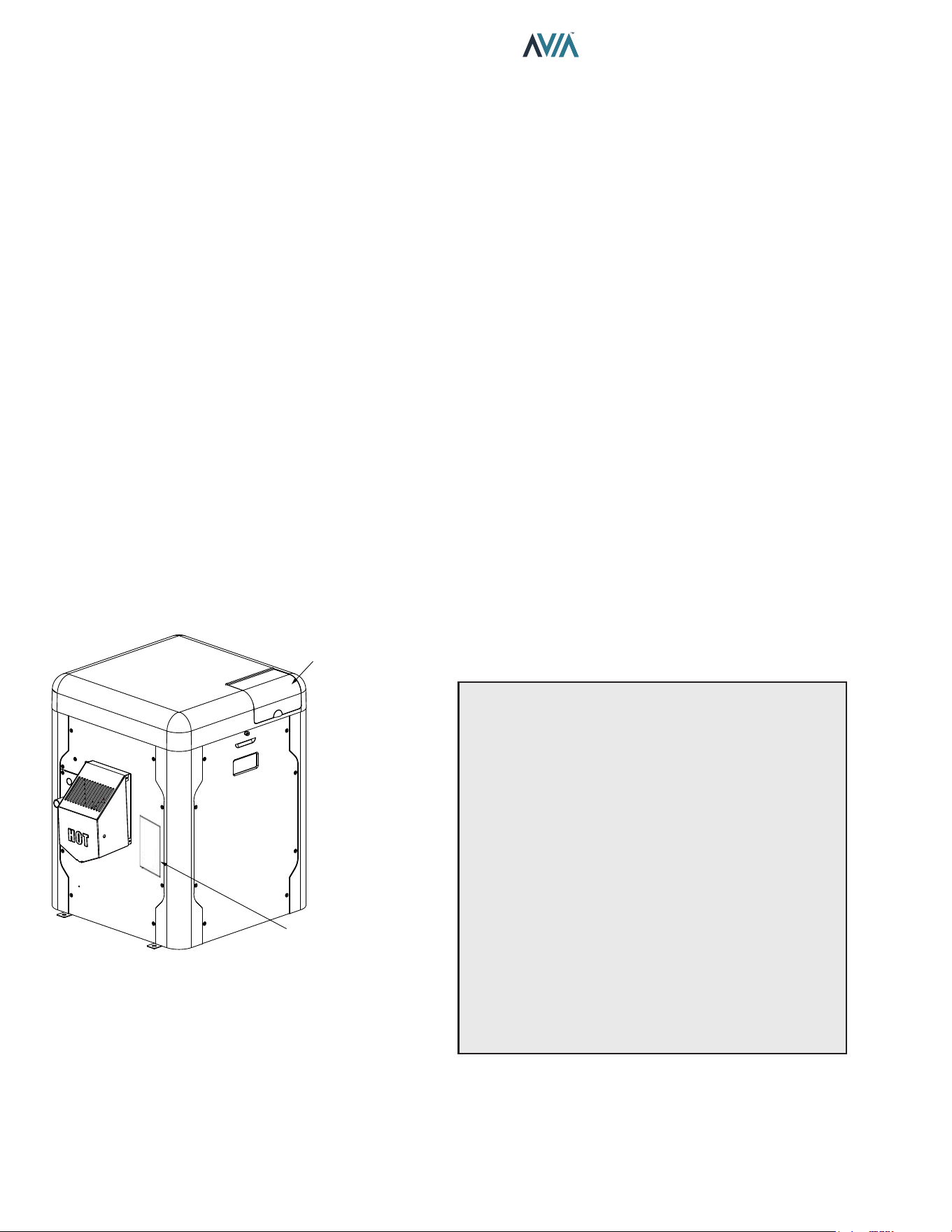
MODEL AND SERIAL NO.
LOCATED ON RATING PLATE
THE MODEL AND SERIAL NO.
CAN ALSO BE FOUND INSIDE
THE BEZEL ABOVE THE DISPLAY
Figure 1. Rating Plate Location
Be sure that you receive the number of packages indicated
on the Bill of Lading.
Rating and Certications
These heaters are design-certied and tested under
the latest requirements of the ANSI Z21.56 / CSA 4.7
and CAN/CGA - 2.17-M91, Standard for Gas-Fired Pool
Heaters. This product is also certied to SCAQMD 1146.2
and SJVAPCD Rule 4308. All heaters can be used either
indoors or outdoors when appropriate venting is installed.
See section "Venting" on page 13 for details. The
appropriate vent cover designated for each type of use is
required.
Elevation
This product is CSA certied up to 4,500 ft. elevation and
is operable up to 10,000 ft. elevation for Natural Gas and
up to 7,800 ft. for Propane. Raypak kit number 018762F
is required for Propane operation between 4,500-7,800 ft.
When installing at altitudes above 4,500 ft., both gas type
pool heater congurations require gas valve adjustments
as needed by a qualied technician.
Required Power Supply
Requires 240VAC (factory default) or 120VAC, 1 Ph, 60
Hz Power Supply. Do not operate on 50 Hz power supply.
Ambient Temperature Rating
Heater Component Temperature Ratings
-32°F to 175°F (-35°C to 79°C).
4. INSTALLATION
A
WARNING: This unit contains refractory ceramic
ber (RCF) insulation in the combustion chamber. RCF,
as manufactured, does not contain respirable crystalline
silica. However, following sustained exposure to very
high temperatures >2192°F (1200°C), the RCF can
transform into crystalline silica (cristabolite). The
International Agency for Research on Cancer (IARC) has
classied the inhalation of crystalline silica (cristabolite)
as carcinogenic to humans.
When removing the burner or heat exchanger, take
precautions to avoid creating airborne dust and avoid
inhaling airborne bers. When cleaning spills, use wet
sweeping or High Eciency Particulate Air (HEPA)
ltered vacuum to minimize airborne dust. Use feasible
engineering controls such as local exhaust ventilation
or dust collecting systems to minimize airborne dust.
Wear appropriate personal protective equipment
including gloves, safety glasses with side shields, and
appropriate NIOSH-certied respiratory protection,
to avoid inhalation of airborne dust and airborne ber
particles.
7
INSTALLATION & OPERATION MANUAL
IMPORTANT NOTICE: These instructions are intended
only for the use by qualied personnel, specically
trained and experienced in the installation of this type
of heating equipment and related system components.
Installation and service personnel may be required by
some states to be licensed. If your state is such, be sure
your contractor bears the appropriate license. Persons
not qualied shall not attempt to x the equipment nor
attempt repairs according to these instructions.
A
WARNING: Improper installation, adjustment,
alteration, service or maintenance may damage the
equipment, create a hazard resulting in asphyxiation,
explosion or re, cause damage which will not be
covered under warranty.
Installation Codes
Installation must be in accordance with local codes, or,
in the absence of local codes, with the latest edition of
the National Fuel Gas Code, ANSI Z223.1/NFPA54 and
National Electrical Code, ANSI/NFPA 70, and for Canada,
the latest edition of CAN/CSA-B149 Installation Codes,
and Canadian Electrical Code, CSA C22.1 Part 1 and
Part 2.
A
AVERTISSEMENT: Cet appareil doit être installé
conformément au National Fuel gas Code ANSI Z223.1,
et aux exigences de l’autorité competente.
Clearances
All Heaters
For indoor and outdoor clearances from combustible
surfaces see Table B below.
Location Indoor Installation
Top Unobstructed
Front 0"
Floor 0"
Back 0"
Right Side 3" (76 mm) from Panel - Water Side
Left Side 3" (76 mm) from Panel - Vented Side
Location Outdoor Installation
Top Unobstructed
Front 0"
Floor 0"
Back 0"
Right Side 3" (76 mm) from Panel - Water Side
Left Side 6" (152 mm) from Vent Cap
Table B. Minimum Clearances from Combustible
Surfaces
For ease of servicing, we recommend a clearance of at
least 24" (610 mm) for both the left and right side, and
also the top. This will enable the heater to be serviced in
its installed location, that is, without needing to move the
header.
Clearances less than these may require removal of the
heater to service either the heat exchanger or the burner.
In either case, the heater must be installed in a manner
that will enable the heater to be serviced without removing
any structure around the heater.
Flooring
This heater can be installed on combustible ooring.
Outdoor Heater Installation
These heaters are design-certied for outdoor installation,
when equipped with the approved vent cover designated
for outdoor use.
A
WARNING: The heater shall not be located in an
area where water sprinklers, or other devices, may cause
water to spray through the cabinet louvers and into the
heater. This could cause internal rusting or damage
electrical components, and void the warranty.
A
WARNING: Do not install within 3' (0.9 m) of a heat
pump or an outdoor condensing unit. Strong air intake
from this type of equipment can disturb the combustion
process and cause damage or personal injury.
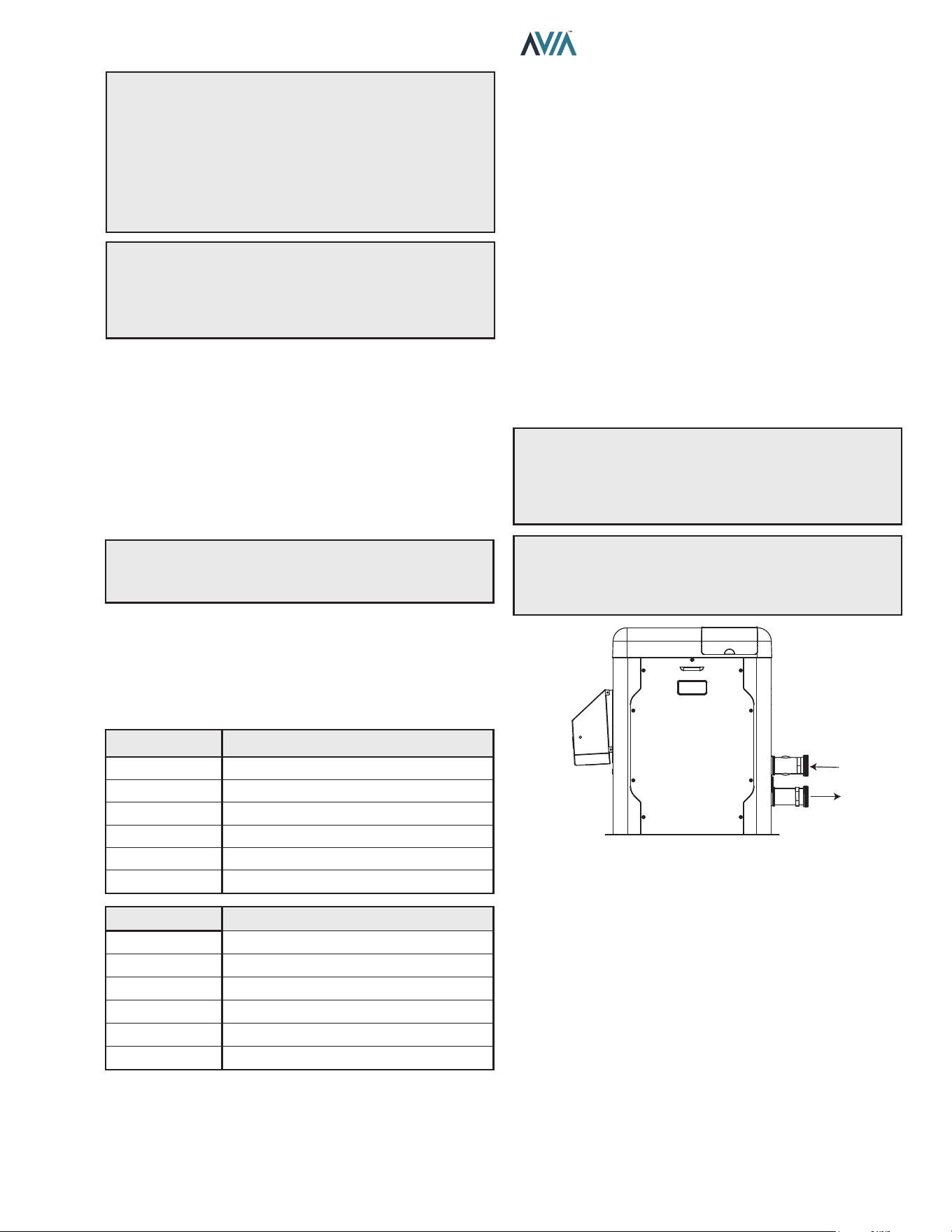
OUTDOOR
VENT COVER
INLET
OUTLET
Figure 2. Front View Of Cabinet Vent/Air Inlet Termination
Clearances
8
INSTALLATION & OPERATION MANUAL
U.S. Installations
1
Canadian Installations
2
A
Clearance above grade, veranda, porch, deck, or
balcony
1' (30 cm) 1' (30 cm)
B Clearance to window or door that may be opened
4' (1.2 m) below or to side of
opening
3' (91 cm)
C Clearance to permanently closed window
* *
D
Vertical clearance to ventilated sot located above the
terminal within a horizontal distance of 2' (61 cm) from
the centerline of the terminal
5' (1.5 m)
*
E Clearance to unventilated sot
* *
F Clearance to outside corner
* *
G Clearance to inside corner 6' (1.83 m)
*
H
Clearance to each side of center line extended above
meter/regulator assembly
*
3' (91 cm) within a height
15' (4.5 m) above the meter/
regulator assembly
I Clearance to service regulator vent outlet
*
6' (1.83 m)
J
Clearance to non-mechanical air supply inlet to
building or the combustion air inlet to any other
appliance
4' (1.2 m) below or to side of
opening; 1' (30 cm) above
opening
3' (91 cm)
K Clearance to mechanical air supply inlet
3' (91 cm) above if within
10' (3 m) horizontally
6' (1.83 m)
L
Do not terminate above paved sidewalk or paved
driveway
Slip hazard due to frozen
condensate
Slip hazard due to frozen
condensate
M Clearance under veranda, porch, deck or balcony
*
1' (30 cm)
t
1
In accordance with the current ANSI Z223.1/NFPA 54 National Fuel Gas Code.
2
In accordance with the current CAN/CSA-B149 Installation Codes.
t
Permitted only if veranda, porch, deck, or balcony is fully open on a minimum of two sides beneath the floor and top of terminal, and underside
of veranda, porch, deck or balcony is greater than 1' (30 cm).
* Clearances in accordance with local installation codes and the requirements of the gas supplier.
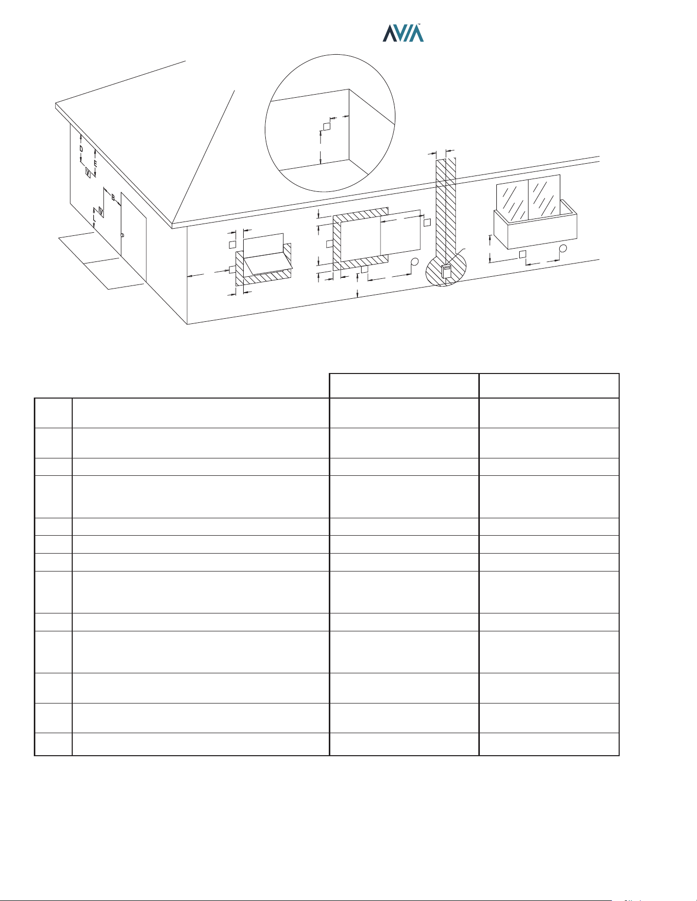
A
INSIDE
CORNER DETAIL
V = VENT
X = AIR INLET
F10692
V
G
H
A
B
B
V
V
B
B
V
A
J
X
I
M
V
X
K
V
V
B
F
C
OPERABLE
FIXED
CLOSED
FIXED
CLOSED
OPERABLE
Table C. Vent/Air Inlet Termination Clearances
Figure 3. Minimum Clearances from Vent/Air Inlet Terminations – Indoor and Outdoor Installations
9
INSTALLATION & OPERATION MANUAL
Description Location
Distance
in. (mm)
a. 3-1/2" (89 mm) thick
masonry walls without
ventilated air space
Back 9 (229)
Right 9 (229)
Left 9 (229)
Vent 5 (127)
Indoor Top 39 (991)
Outdoor Top Unobstructed
b. 1/2" (13 mm) insulation
board over 1" (25 mm)
glass ber or mineral
wool batts
Back 6 (152)
Right 6 (152)
Left 6 (152)
Vent 3 (76)
Indoor Top 30 (762)
Outdoor Top Unobstructed
c. 0.024 sheet metal over
1" (25 mm) glass ber
or mineral wool batts
reinforced with wire on
rear face with ventilated
air space
Back 4 (102)
Right 4 (102)
Left 4 (102)
Vent 3 (76)
Indoor Top 24 (610)
Outdoor Top Unobstructed
d. 3-1/2" (89 mm) thick
masonry wall with
ventilated air space
Back 6 (152)
Right 6 (152)
Left 6 (152)
Vent 6 (152)
Indoor Top 39 (991)
Outdoor Top Unobstructed
e. 0.024 sheet metal with
ventilated air space
Back 4 (102)
Right 4 (102)
Left 4 (102)
Vent 2 (51)
Indoor Top 24 (610)
Outdoor Top Unobstructed
f. 1/2" (13 mm) thick
insulation board with
ventilated air space
Back 4 (102)
Right 4 (102)
Left 4 (102)
Vent 3 (76)
Indoor Top 24 (610)
Outdoor Top Unobstructed
g. 0.024 sheet metal with
ventilated air space over
0.024 sheet metal with
ventilated air space.
Back 4 (102)
Right 4 (102)
Left 4 (102)
Vent 3 (76)
Indoor Top 24 (610)
Outdoor Top Unobstructed
h. 1" (25 mm) glass ber
or mineral wool batts
sandwiched between two
sheets 0.024 sheet metal
with ventilated air space
Back 4 (102)
Right 4 (102)
Left 4 (102)
Vent 3 (76)
Indoor Top 24 (610)
Outdoor Top Unobstructed
Derived from National Fuel Gas Code, Table 10.2.3
Table D. Reduction of Clearances to Protected Surfaces
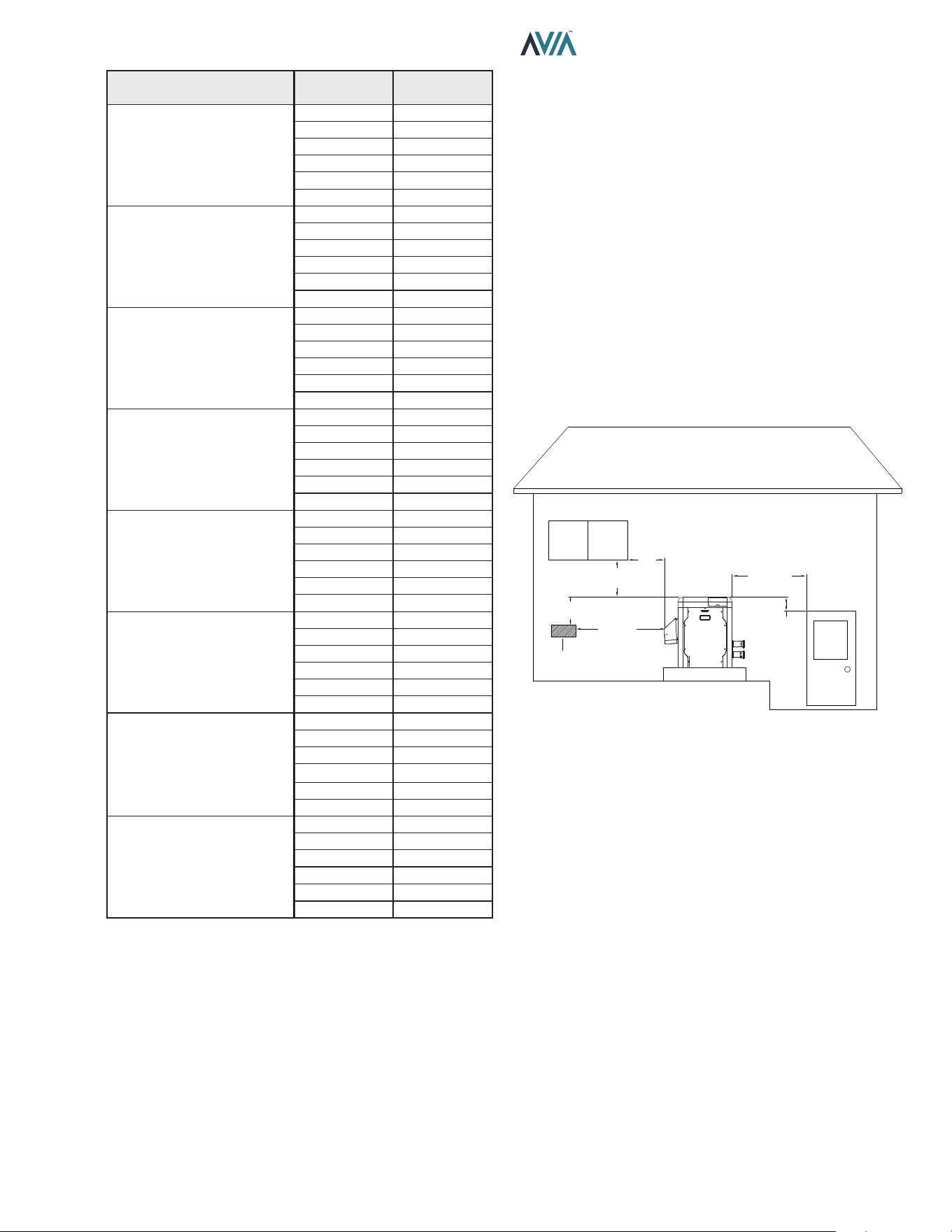
Heaters must not be installed under an overhang of less
than three 3' (0.9 m) from the top of the heater. Three sides
must be open in the area under the overhang. Roof water
drainage must be diverted away from the heaters installed
under overhangs with the use of gutters.
For U.S. installations, the point from where the ue
products exit the heater must be a minimum of 4' (1.2 m)
below, 4' (1.2 m) horizontally from, or 1' (0.3 m) above any
door, window or gravity inlet into any building. The top
surface of the heater shall be at least 3' (0.9 m) above
any forced air inlet, or intake ducts located within 10' (3 m)
horizontally.
For Canadian installations, pool heaters shall not be
installed with the top of the vent assembly within 10' (3 m)
below, or to either side, of any opening into the building.
Refer to the latest revisions of CAN/CSA-B149.
A minimum of 6' (1.8 m) is required from the heater to an
inside corner wall for proper outdoor venting.
For installations in Florida and Texas, that must comply
with the Florida or Texas Building Code, follow the directions
shown in Figure 5 for the installation of hurricane tie-down
brackets for all models.
4' (1.2 m)
MIN
4' (1.2 m)
MIN
4' (1.2 m)
MIN
3' (0.9 m)
MIN
10' (3 m)
MIN
4' (1.2 m)
MIN
FORCED AIR
INLET
Figure 4. Clearances
Indoor Heater Installation
For Canada, indoor installation is restricted to an enclosure
that is not occupied and does not directly communicate
with an occupied area. Refer to the latest edition of CAN/
CSA-B149 for specic requirements. Locate heater as
close as is practical to a chimney or gas vent. Heater must
always be vented to the outside. See "Venting" section on
page 13 for details. Minimum allowable space is shown
on the nameplate.
10
INSTALLATION & OPERATION MANUAL
Combustion and Ventilation Air
Indoor Units Only
The heater must have both combustion and ventilation
air. The minimum requirements are listed in the latest
edition of the National Fuel Gas Code (U.S. ANSI Z223.1
or Canada CAN/CSA-B149) and any local codes that
may have jurisdiction. The most common approach is
the “2-opening” method, with combustion air opening no
more than 12" (305 mm) from the oor and the ventilation
opening no more than 12" (305 mm) from the ceiling. For
opening sizes using this method, see below.
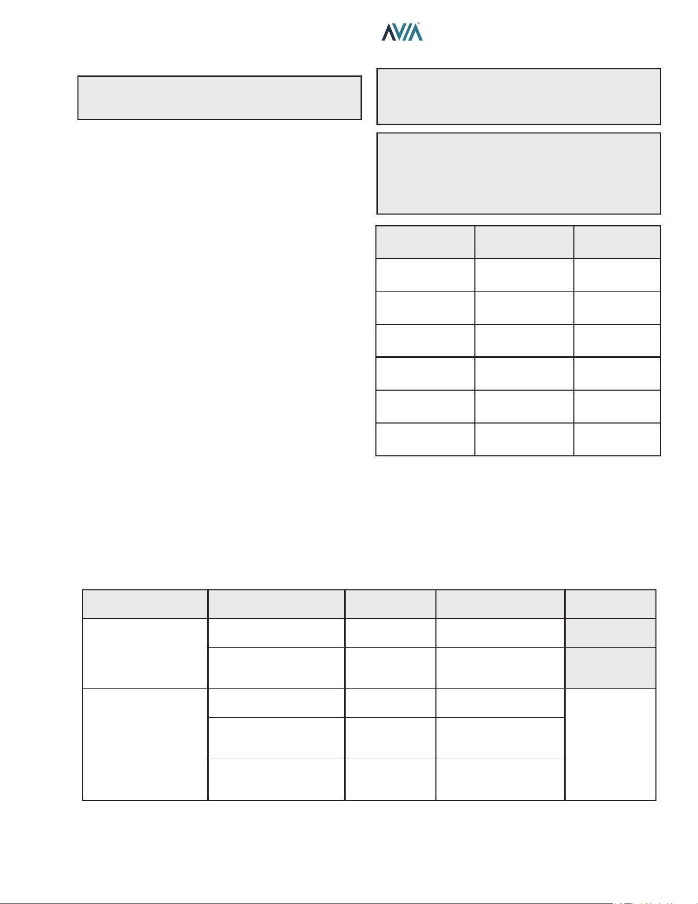
All Air from Inside the Building:
Each opening shall have a minimum net free area as
noted:
Model Sq. in. (m²)
264 264 (0.17)
404 399 (0.26)
Table E. Opening Minimum Net Free Requirements -
Indoor Air
All Air from Outdoors:
When air is supplied directly from outside the building, each
opening shall have a minimum net free area as noted:
Model
Unrestricted
Opening
sq. in. (m²)
Typical Screened
or Louvered
Opening
sq. in. (m²)
Typical Screened
and Louvered
Opening
sq. in. (m²)
264 66 (0.04) 99 (0.06) 132 (0.09)
404 100 (0.06) 150 (0.1) 200 (0.13)
Table F. Opening Minimum Net Free Requirements -
Outdoor Air
A
CAUTION: Combustion air must not be contaminated
by corrosive chemical fumes which can damage the
heater. Such damage will not be covered by the warranty
Direct Vent and Ducted
Combustion Air Systems
If outside air is drawn through the intake pipe directly to the
unit for combustion:
1. Connect combustion air to the heater by removing
the screened cap on the air intake port, and sealing
the combustion air duct to the existing PVC adapter.
Glue or attach screws to fasten. The existing screen
should be re-used at the intake end of the duct. Install
the combustion air duct in accordance with Figure
11 or Figure 12 of this manual.
2. Provide adequate ventilation of the space occupied
by the heater(s) by an opening(s) for ventilation air
at the highest practical point communicating with the
outdoors.
A. In the United States, the total cross-sectional
area shall be at least 1 in.² of free area per
20,000 BTUH (111 mm² per kW) of total input
rating of all equipment in the room when the
opening is communicating directly with the
outdoors or through vertical duct(s). The total
cross-sectional area shall be at least 1 in.² of free
area per 10,000 BTUH (222 mm² per kW) of total
input rating of all equipment in the room when
the opening is communicating with the outdoors
through horizontal duct(s).
B. In Canada, there shall be permanent air supply
opening(s) having a total cross-sectional area of
not less than 1 in.² of free area per 30,000 BTUH
(70 mm² per kW) of the total rated input. The
location of the opening(s) shall not interfere with
the intended purpose of the opening(s) for the
ventilation air.
3. In cold climates, and to mitigate potential freeze-
up, Raypak highly recommends the installation of a
motorized sealed damper to prevent the circulation of
cold air through the heater during the non-operating
hours.
11
INSTALLATION & OPERATION MANUAL
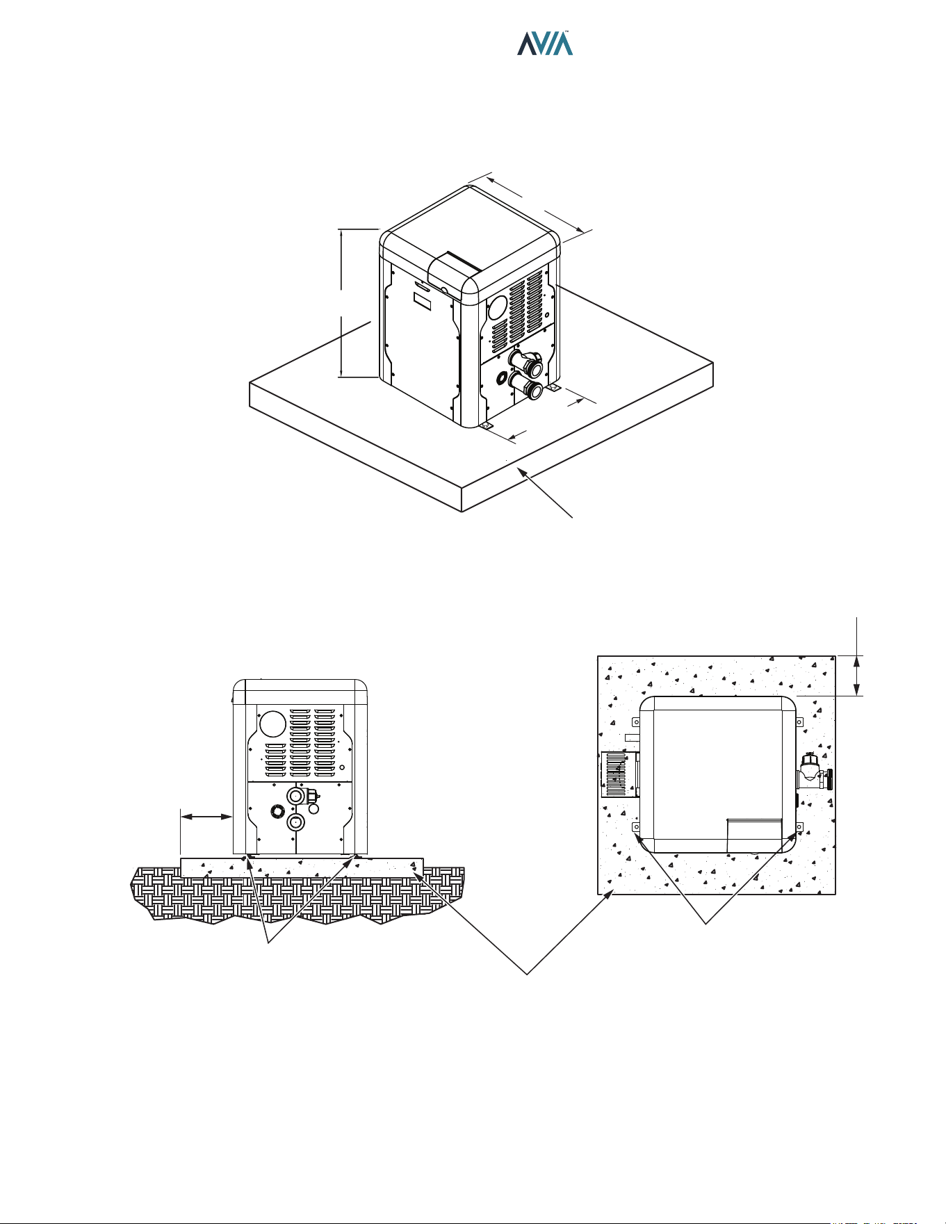
29" (73.6 cm)
3" (76 mm)
Min. Conc.
Pad by others
3" (76 mm)
Min. Conc.
Pad by others
(1)–1/4" x 2-1/4" S.S. Tapcon
Bolt & Washer (Field-Supplied)
Ea. Pallet Anchor Bracket
Use hole closest to unit (4 total)
(1)–1/4" x 2-1/4" S.S.
Tapcon Bolt & Washer (Field-Supplied)
Ea. Pallet Anchor Bracket
Use hole closest to unit (4 total)
Min. Edge
Distance
6"
(152 mm)
Min. Edge
Distance
6"
(152 mm)
16.92"
(43.0 cm)
30.38"
(77.1 cm)
Florida and Texas Building Code:
Wind Speed = 180 mph 3-sec. Gust
Exposure = C
Figure 5. Hurricane Tie-Down Bracket Installation
12
INSTALLATION & OPERATION MANUAL
Model No.
BTUH
Input
(kw)
Flue
Dia.
in. (mm)
Water
Conn.
in. (mm)
Shipping Weights - lbs (kg)
Standard
Heater
264
264
(77.4)
4
(101.6)
2 (51)
Buttress
135
(61.2)
+20 (9) Packing
404
399
(116.9)
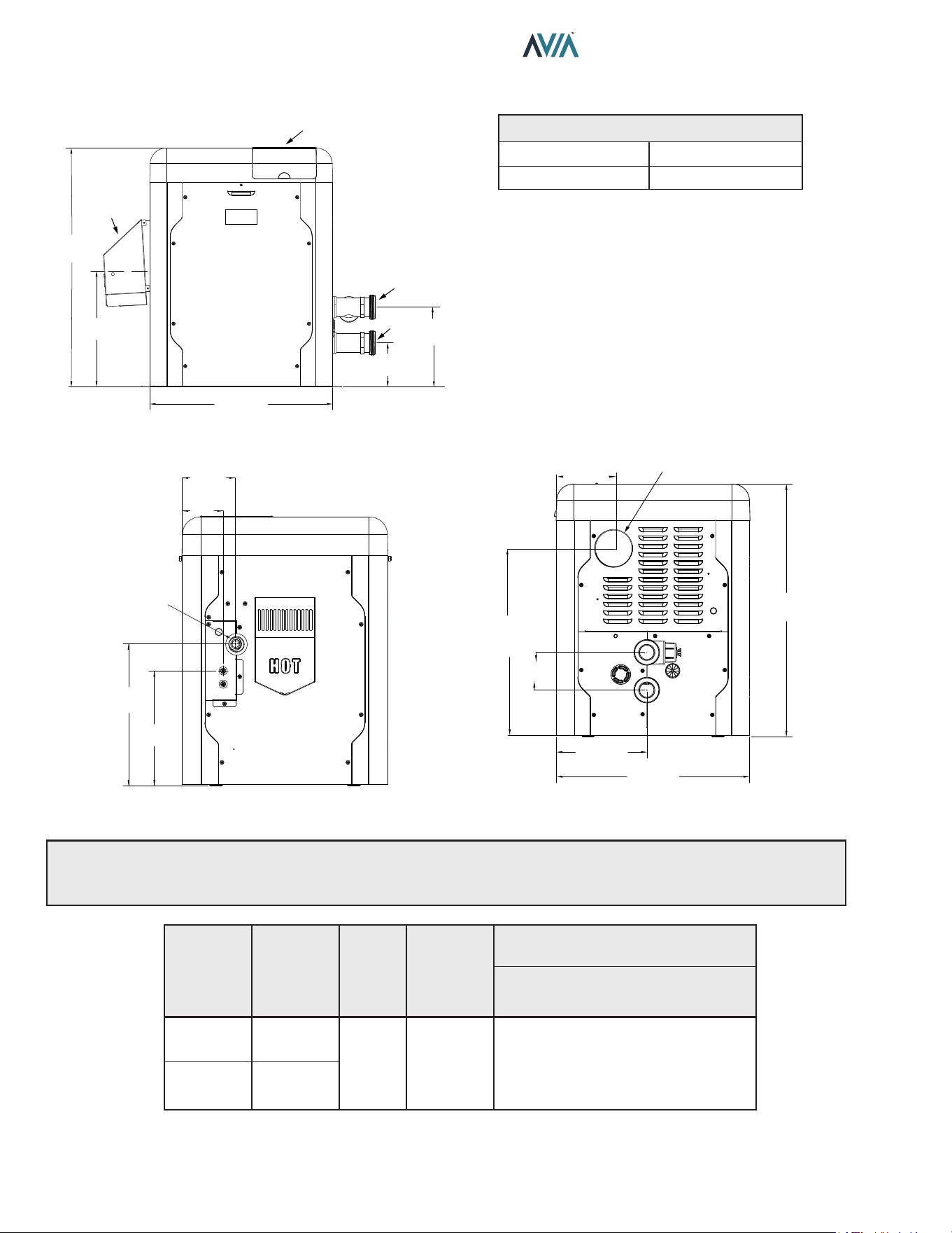
Table G. Heater Specications and Dimensions
Specications and Dimensions
Figure 6. Front View
5.61”
(143 MM)
10.14”
(258 MM)
23.24”
(590 MM)
14.63”
(372 MM)
30.38”
(772 MM)
CONTROL DISPLAY
AND INTERFACE
OUTDOOR FLUE
COVER
F10815
Water Inlet
Water Outlet
KNOCKOUT FOR 4”
COMBUSTION AIR DUCT
6.89”
(175 mm)
22.64”
(575 mm)
4.53”
(115 mm)
10.86”
(276 mm)
23.22”
(590 mm)
30.38”
(772 mm)
F10816
Amp Draw
120 VAC, 1 Ph, 60 Hz 240 VAC, 1 Ph, 60 Hz
1.6 Amps 1.2 Amps
Figure 7. Left View with Gas & Power Connection
Distances
A
WARNING: The Commonwealth of Massachusetts requires that sidewall-vented heaters, installed in every
dwelling, building or structure used in whole or in part for residential purposes, be installed using special provisions
as outlined on page 93 of this manual.
5.99”
(150 mm)
4.63”
(116 mm)
3/4”
(19 mm)
NPT Gas
16.02”
(406 mm)
12.98”
(330 mm)
Figure 8. Right View
13
INSTALLATION & OPERATION MANUAL
Venting
A
CAUTION: Proper installation of ue venting is
critical for the safe and ecient operation of the pool
heater.
General
Appliance Categories
Heaters are divided into four categories based on the
pressure produced in the exhaust and the likelihood of
condensate production in the vent.
Category I – A heater which operates with a non-positive
vent static pressure and with a vent gas temperature that
avoids excessive condensate production in the vent.
Category II – A heater which operates with a non-positive
vent static pressure and with a vent gas temperature that
may cause excessive condensate production in the vent.
Category III – A heater which operates with a positive
vent pressure and with a vent gas temperature that avoids
excessive condensate production in the vent.
Category IV – A heater which operates with a positive vent
pressure and with a vent gas temperature that may cause
excessive condensate production in the vent.
See Table H for appliance category requirements.
Combustion
Air Supply
Exhaust Conguration
Heater Venting
Category
Certied Vent Materials
Combustion Air
Inlet Material
From Inside Building
Vertical Venting
I
Fan
B-Vent
Equivalent
Horizontal Through-the-Wall
Venting
III
UL 1738
Metallic Vent
(such as AL29-4C)
From Outside Building
(Direct Vent or Ducted
Combustion Air)
Vertical Venting with Ducted
Combustion Air
I
Fan
B-Vent
Equivalent
Galvanized Steel,
PVC, ABS,
CPVC
Vertical
Direct Vent
III
UL 1738
Metallic Vent
(such as AL29-4C)
Horizontal
Direct Vent
III
UL 1738
Metallic Vent
(such as AL29-4C)
Table H. Venting Category Requirements
NOTE: For additional information on appliance
categorization, see the ANSI Z21.13 Standard and the
NFGC (U.S.), or B149 (Canada), or applicable provisions
of local building codes.
A
WARNING: Contact the manufacturer of the vent
material if there is any question about the appliance
categorization and suitability of a vent material for
application on a Category I vent system. Using improper
venting materials can result in personal injury, death or
property damage.
Description
(Terminations)
Manufacturer
Manufacturer
Model Number
Through-the-wall Duravent FSTB4
Horizontal Tee Duravent FSTT4
Horizontal Tee Z-Flex 2SVSTTF04
Wall Thimble with
Damper
Duravent PRTFSWTT4
90-degree Elbow Z-Flex 2SVSTEX0490
D15 - Vertical
Horizontal Cap
Raypak 014289
Table I. Vent Terminations
Note: For appliance adapter
use Duravent FSAAU4 or
Z-Flex 2SVSNA04.5

14
INSTALLATION & OPERATION MANUAL
Support of Vent Stack
The weight of the vent stack or chimney must not rest
on the heater vent connection. Support must be provided
in compliance with applicable codes. The vent should
also be installed to maintain proper clearances from
combustible materials. Use insulated vent pipe spacers
where the vent passes through combustible roofs and
walls.
Vent Terminal Location
1. Condensate can freeze on the vent cap. Frozen
condensate on the vent cap can result in a blocked
flue condition.
2. Give special attention to the location of the vent
termination to avoid possibility of property damage or
personal injury.
3. Gases may form a white vapor plume in winter. The
plume could obstruct a window view if the termination
is installed near windows.
4. Prevailing winds, in combination with below-freezing
temperatures, can cause freezing of condensate and
water/ice build-up on buildings, plants or roofs.
5. The bottom of the vent terminal and the air intake
shall be located at least 12 in. (305 mm) above grade,
including normal snow line.
6. Un-insulated single-wall metal vent pipe shall not be
used outdoors in cold climates for venting gas-fired
equipment.
7. Through-the-wall vents for Category II and IV
appliances and non-categorized condensing appli-
ances shall not terminate over public walkways
or over an area where condensate or vapor could
create a nuisance or hazard or could be detrimental
to the operation of regulators, relief valves, or other
equipment. Where local experience indicates that
condensate is a problem with Category I and III
appliances, this provision shall also apply.
8. Locate and guard vent termination to prevent acci-
dental contact by people or pets.
9. DO NOT terminate vent in window well, stairwell,
alcove, courtyard or other recessed area.
10. DO NOT terminate above any door, window, or
gravity air intake. Condensate can freeze, causing
ice formations.
11. Locate or guard vent to prevent condensate from
damaging exterior finishes. Use a rust-resistant
sheet metal backing plate against brick or masonry
surfaces.
12. DO NOT extend exposed vent pipe outside of building
beyond the minimum distance required for the vent
termination. Condensate could freeze and block the
vent pipe.
U.S. Venting Installations
Refer to the latest edition of the National Fuel Gas Code.
Vent termination requirements are as follows:
1. Vent must terminate at least 4 ft. (1.2 m) below, 4 ft.
(1.2 m) horizontally from or 12 in. (305 mm) above
any door, window or gravity air inlet to the building.
2. The vent must not be less than 7 ft. (2.1 m) above
grade when located adjacent to public walkways.
3. Terminate vent at least 3 ft. (0.9 m) above any forced
air inlet located within 10 ft. (3.0 m).
4. Vent must terminate at least 4 ft. (1.2 m) horizontally,
and in no case above or below, unless a 4 ft. (1.2
m) horizontal distance is maintained from electric
meters, gas meters, regulators, and relief equipment.
5. Terminate vent at least 6 ft. (1.8 m) away from
adjacent walls.
6. DO NOT terminate vent closer than 5 ft. (1.5 m)
below roof overhang.
7. The vent terminal requires a 12 in. (305 mm) vent
terminal clearance from the wall.
8. Terminate vent at least 12 in. (305 mm) above grade,
including normal snow line.
9. Multiple direct vent installations require a 4 ft. (1.2 m)
clearance between the ends of vent caps located on
the same horizontal plane.
Canadian Venting Installations
Refer to latest edition of the B149 Installation code.
A vent shall not terminate:
1. Directly above a paved sidewalk or driveway which
is located between two single-family dwellings and
serves both dwellings.
2. Less than 7 ft. (2.13 m) above a paved sidewalk or
paved driveway located on public property.
3. Within 6 ft. (1.8 m) of a mechanical air supply inlet to
any building.
4. Above a meter/regulator assembly within 3 ft. (915 mm)
horizontally of the vertical centerline of the regulator.
5. Within 3 ft. (0.9 m) of any gas service regulator vent
outlet.
6. Less than 12 in. (305 mm) above grade level.
7. Within the 3 ft. (915 mm) of a window or door which
can be opened in any building, any non-mechanical air
supply inlet to any building or the combustion air inlet
of any other appliance.
8. Underneath a veranda, porch or deck, unless the
veranda, porch or deck is fully open on a minimum of
two sides beneath the floor, and the distance between
the top of the vent termination and the underside of the
veranda, porch or deck.
15
INSTALLATION & OPERATION MANUAL
Venting Installation Tips
Support piping:
• horizontal runs—at least every 5 ft. (1.5 m)
• vertical runs—use braces
• under or near elbows
Venting Congurations
For heaters connected to gas vents or chimneys, vent
installations shall be in accordance with the NFGC (U.S.),
or B149 (Canada), or applicable provisions of local building
codes.
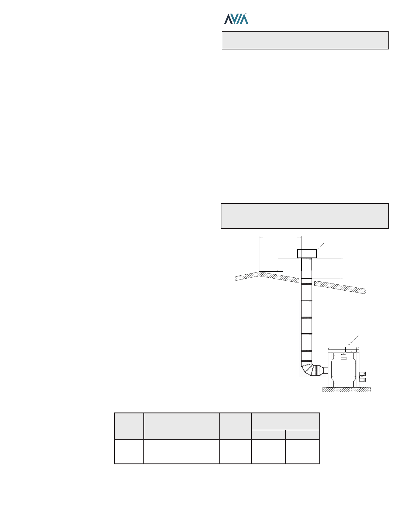
Vertical Venting (Category I) Fan-Assisted
Installation
Natural draft venting uses the natural tendency of the
heated ue gases to rise, until they are expelled from the
top of the ue. The negative draft must be within the range
of -.01 to -.08 in. WC as measured 12 in. (305 mm) above
the appliance ue outlet to ensure proper operation. Vent
material must be listed by a nationally recognized test
agency.
B-vent increasers will be required for adequate carrying
capacity, per the National Fuel Gas Code.
Double-wall Type B vent must be used to promote draft
and to minimize condensation in the vent.
No drafthood is required or oered. A single-acting
barometric damper is required if the height exceeds 25
feet (7.6 m).
The connection from the appliance vent to the stack must
be as direct as possible. The horizontal breaching of a
vent must have an upward slope of not less than 1/4 inch
per linear foot from the heater to the vent terminal. The
horizontal portions of the vent shall also be supported for
the design and weight of the material employed to maintain
clearances and to prevent physical damage or separation
of joints.
The maximum and minimum venting length for Category
I appliances shall be determined per the NFGC (U.S.) or
B149.1 (Canada).
The diameter of the vent ue pipe should be sized
according to the NFGC (U.S.) and B149.1 (Canada). The
minimum ue pipe diameter for conventional negative draft
venting using double-wall Type B vent is 5 inches (12.7
cm) for Model 264 and 6 inches (15.2 cm) for Model 404.
NOTE: A vent adapter (eld-supplied) must be used to
connect Type B vent to the unit.
Termination
The vent terminal should be vertical and should terminate
outside the building at least 2 ft. (0.6 m) above the highest
point of the roof that is within 8 ft. (2.4 m). The vent cap
should have a minimum clearance of 4 ft. (1.2 m) horizontally
from and in no case above or below electric meters, gas
meters, regulators and relief equipment, unless a 4 ft. (1.2
m) horizontal distance is maintained. The distance of the
vent terminal from adjacent public walkways, adjacent
buildings, open windows and building openings must be
consistent with the NFGC (U.S.) or B149 (Canada). Gas
vents supported only by ashing and extended above the
roof more than 5 ft. (1.5 m) should be securely guyed or
braced to withstand snow and wind loads.
For factory approved vent termination caps, refer to the
Illustrated Parts List (IPL) section of this manual. See page
84.
CAUTION: A listed vent cap terminal adequately sized,
must be used to evacuate the ue products from the
building.
HEATER
2” MIN
(0.6 M)
VENT CAP
2” MIN
(0.6 M)
8” OR LESS
(0.6 M)
Figure 9. Vertical Venting
Model
No.
Certied
Vent
Material
Vent Size
in. (mm)
Vertical Vent Height
ft. (m)*
Min. Max.
264/404
Category I
(Type B Equivalent)
Fan-Assisted
4 (101.6) 5 (1.5) 25 (7.6)
Vent lengths are based on a lateral length of 2 ft. (0.6 m). Refer to the latest edition of the NFGC for further details. When vertical height
exceeds 25 ft. (7.6 m), consult factory prior to installation.
*Subtract 12 ft. (3.6 m) per elbow.
Table J. Category I Vertical Venting
16
INSTALLATION & OPERATION MANUAL
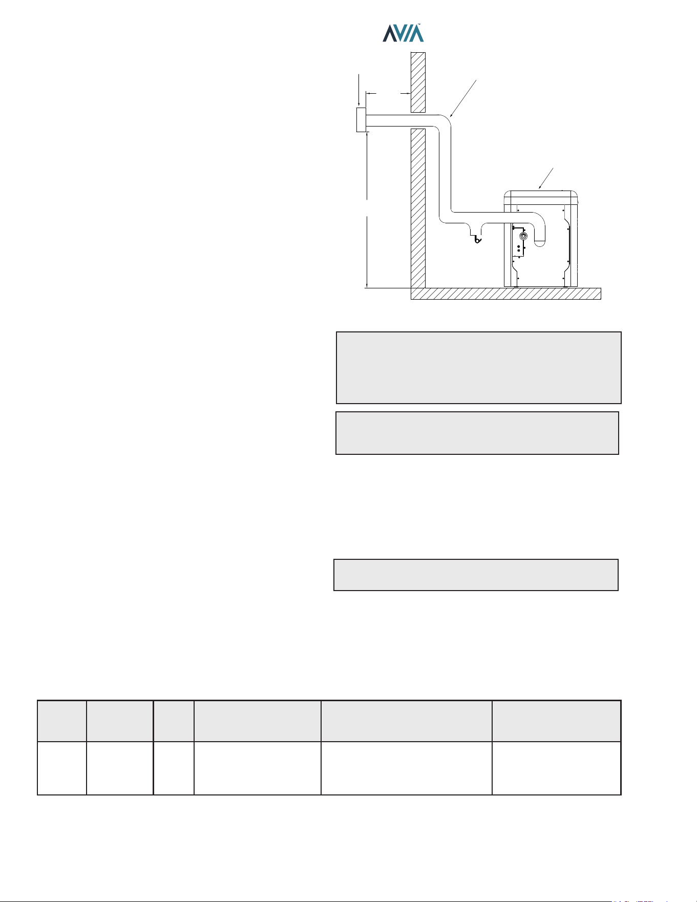
Horizontal Through-the-Wall Venting
(Category III)
Installation
These installations utilize the heater’s internal blower to
vent the combustion products to the outdoors. Combustion
air is taken from inside the room and the vent is installed
horizontally through the wall to the outdoors. Adequate
combustion and ventilation air must be supplied to the
equipment room in accordance with the NFGC (U.S.) or
B149 (Canada).
The total length of the horizontal through-the-wall ue
system should not exceed 75 equivalent ft. (22.86 m) in
length. If horizontal run exceeds 75 equivalent ft. (22.86
m), an appropriately-sized variable-speed extractor must
be used. Each elbow used is equal to 12 ft. (3.6 m) of
straight pipe.
The vent cap is not considered in the overall length of the
venting system.
The vent must be installed to prevent ue gas leakage.
Care must be taken during assembly to ensure that all
joints are sealed properly and are airtight. The vent must
be installed to prevent the potential accumulation of
condensate in the vent pipes. It is recommended that the
vent be insulated. Insulation is required for installations in
cold environments (i.e. below 40°F or 4°C). It is required
that:
The vent must be installed with a condensate drain
located in proximity to the heater as directed by the vent
manufacturer.
The vent must be installed with a slight upward slope of
not less than 1/4 inch per foot of horizontal run to the vent
terminal.
Termination
The vent cap MUST be mounted on the exterior of the
building. The vent cap cannot be installed in a well or
below grade. It must be installed at least 12" (305 mm)
above ground level and above normal snow levels. The
vent terminal must be located NO CLOSER than 12" (305
mm) o the wall.
For factory approved vent termination caps, refer to the
Illustrated Parts List (IPL) section of this manual. See
page 84.
INSULATED EXHAUST
VENTING
FLUE EXHAUST
VENT CAP
HEATER
12" MIN
(305 mm)
12" MIN
(305 mm)
CONDENSATION
TRAP
Figure 10. Horizontal Through-the-Wall Venting
CAUTION: This venting system requires the installation
of a condensate drain in the vent piping per the vent
manufacturer's instructions. Failure to install a condensate
drain in the venting system will cause damage which will
not be covered under warranty.
A
WARNING: No substitutions of ue pipe or vent
cap material are allowed. Such substitutions would
jeopardize the safety and health of inhabitants.
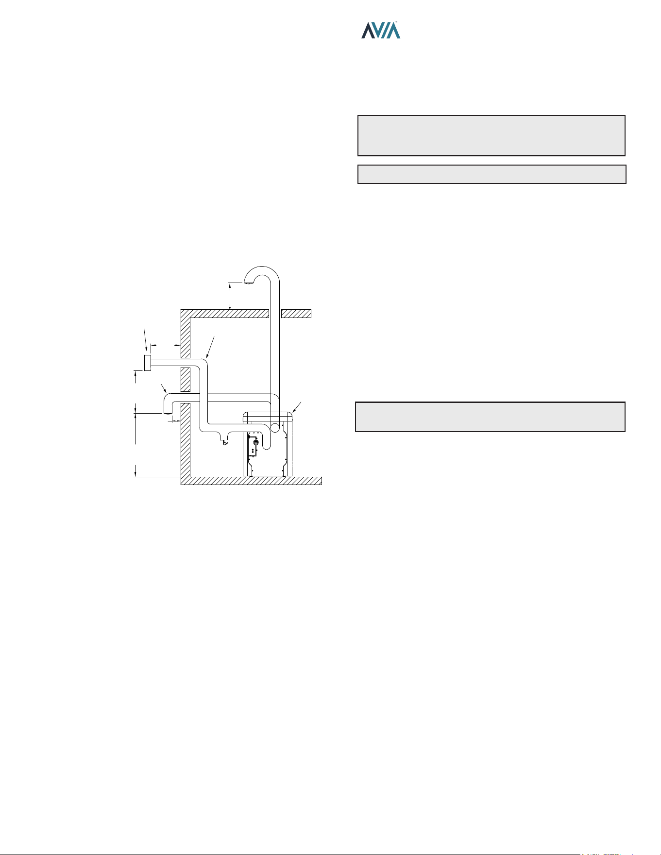
Direct Vent - Horizontal Through-the-Wall
Installation
These installations utilize the heater’s internal blower to
draw combustion air from outdoors and vent combustion
products to the outdoors, see Table K.
NOTE: Use of B-vent on such a system does not meet
direct-vent requirements.
The exhaust and intake systems must be installed to
prevent the potential accumulation of condensate. It is
recommended that they be insulated. Insulation is required
for installations in cold environments (i.e. below 40°F (4°C).
The ue termination cap is not considered in the overall
length of the venting system.
Model
No.
Certied
Vent
Material
Vent
Size
ft. (m)
Maximum
Vent Length
ft. (m)*
Combustion Air Intake
Pipe Material**
Air Intake Max. Length*
ft. (m)
4" Ø
264/404 Category III 4 (1.2) 75 (22.86)
Galvanized Steel,
PVC,
ABS,
CPVC
75 (22.86)
* Subtract 12 ft. (3.6 m) per elbow.
** Schedule 40 in PVC or CPVC.
Table K. Category III Horizontal Vent & Horizontal Direct Vent
17
INSTALLATION & OPERATION MANUAL
Care must be taken during assembly that all joints are
sealed properly and are airtight.
The vent must be installed to prevent the potential
accumulation of condensate in the vent pipes. It is
recommended that the vent be insulated. Insulation is
required for installations in cold environments (i.e., below
40°F (4°C).
For installations in extremely cold climates, it is required
that:
1. The vent must be installed with a slight upward slope
of not more than 1/4 inch per foot of horizontal run to
the vent terminal. An approved condensate trap must
be installed per applicable codes.
2. The air intake vent must be insulated through the
length of the horizontal run.
HEATER
12" MIN
(305 mm)
CONDENSATION
TRAP
AIR
INTAKE
ALTERNATE COMBUSTION
AIR INTAKE LOCATION
HORIZONTAL
TERMINATION CAP (D-15)
INSULATED EXHAUST
VENTING
12” MIN
(305 mm)
6” MIN
(153 mm)
36” MIN
(915 mm)
12” MIN
(305 mm)
Figure 11. Horizontal Through-the-Wall Direct Venting
Termination
The exhaust vent cap MUST be mounted on the exterior
of the building, and cannot be installed in a well or below
grade. It must be installed at least 12" (305 mm) above
ground level and above normal snow levels.
The exhaust vent cap MUST NOT be installed below or
closer than 3 ft. (0.9 m) from the air intake. Venting any
closer to the air intake will cause combustion gases to
recirculate into the heater.
This type of installation can cause non-warrantable
problems with components and poor operation of the
heater due to the recirculation of ue products. Multiple
vent caps should be installed in the same horizontal plane
with a 4 ft. (1.2 m) minimum clearance from the side of
one vent cap to the side of the adjacent vent cap(s). See
Figure 11.
Combustion air supplied from outdoors must be free of
particulate and chemical contaminants. To avoid a blocked
ue condition, keep the vent cap clear of snow, ice, leaves,
debris, etc.
Use only the special gas vent pipes listed for use with
Category III gas burning heaters, such as the AL29-
4C stainless steel vents oered by DuraVent (www.
duravent.com). Follow the vent manufacturer’s installation
instructions carefully.
A
WARNING: No substitutions of ue pipe or vent
cap material are allowed. Such substitutions would
jeopardize the safety and health of inhabitants.
A
CAUTION: Condensate is acidic and highly corrosive.
Direct Vent—Vertical
Installation
These installations utilize the heater-mounted blower to
draw combustion air from outdoors and force the heated
ue products through the vent pipe under positive pressure.
The vent material must be in accordance with the above
instructions for vent materials. Vent material must be listed
by a nationally recognized test agency.
The connection from the appliance ue to the stack must
be as direct as possible and should be the same size or
larger than the vent outlet.
It is recommended that the intake vent be insulated in
colder climates.
NOTE: Use of B-vent on such a system does not meet
direct-vent requirements.
Termination
The ue should be vertical and should terminate outside
the building at least 2 ft. (0.6 m) above the highest point
of the roof within 10 ft. (3.0 m). The vent cap should have
a minimum clearance of 4 ft. (1.2 m) horizontally from
and in no case above or below (unless a 4 ft. (1.2 m))
horizontal distance is maintained) electric meters, gas
meters, regulators and relief equipment. The distance of
the vent terminal from adjacent public walkways, adjacent
buildings, open windows and building openings must be
consistent with the NFGC (U.S.) or B149 (Canada).
Vent pipes supported only by ashing and extended above
the roof more than 5 ft. (1.5 m) should be securely guyed
or braced to withstand snow and wind loads.
The air inlet opening MUST be installed 1 ft. (305 mm)
above the roof line or above normal snow levels that might
obstruct combustion air ow. This dimension is critical to
the correct operation of the heater and venting system and
reduces the chance of blockage from snow. The vent cap
must have a minimum 3 ft. (0.9 m) vertical clearance from
the air inlet opening.
Use only the special gas vent pipes listed for use with
Category III gas burning heaters, such as the AL29-4C
stainless steel vents oered by DuraVent (www.duravent.
com). Pipe joints must be positively sealed. Follow the
vent manufacturer’s installation instructions carefully.
18
INSTALLATION & OPERATION MANUAL
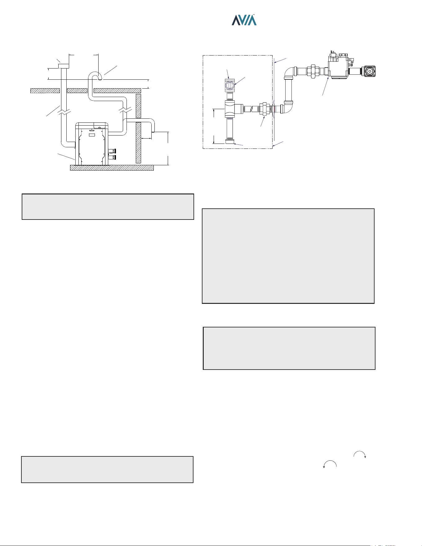
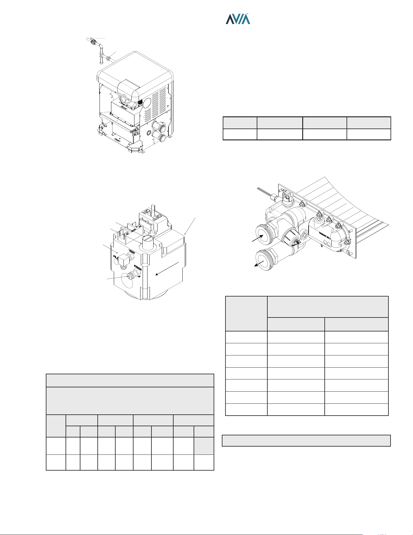
Gas Supply Connections
GAS VALVE
HEATER
JACKET
3" MIN
(7.6 cm)
TYPICAL
FIELD-SUPPLIED
SEDIMENT
TRAP
UNION
GAS
SUPPLY
INLET
MANUAL
SHUTOFF
VALVE
Figure 13. Gas Supply Plumbing
Gas piping must have a sediment trap ahead of the heater
gas controls, and a manual shuto valve located outside
the heater jacket. All gas piping should be tested after
installation in accordance with local codes.
A
CAUTION: The heater and its manual shuto valve
must be disconnected from the gas supply during any
pressure testing of that system at test pressures in
excess of 1/2 psi (3.45 kPa). Dissipate test pressure in
the gas supply line before reconnecting the heater and
its manual shuto valve to gas supply line. FAILURE
TO FOLLOW THIS PROCEDURE MAY DAMAGE THE
GAS VALVE. OVER-PRESSURIZED GAS VALVES ARE
NOT COVERED BY WARRANTY. The heater and its gas
connections shall be leak-tested before placing the
appliance in operation. Use soapy water for leak test. DO
NOT use open ame.
Supply Pressure
A
CAUTION: Do not use Teon tape on gas line pipe
thread. Only sealant tape or a pipe compound rated for
use with natural and propane gases is recommended.
Apply sparingly only on male pipe ends, leaving the two
end threads bare.
A minimum of 3.5 in. WC and a maximum of 10.5 in. WC
upstream pressure under load and no-load conditions
must be provided for natural gas. Required pressure for
Propane Gas: Min = 8.0" WC (Dynamic), Max = 13" WC
(Static).
Gas Pressure Regulator
The gas manifold pressure is preset to a negative -0.30"
WC. If an adjustment is needed, remove the gas valve
throttle seal and turn adjustment screw clockwise to
increase pressure or counter-clockwise to decrease
pressure. If available, the O2 must be within 4.5 - 5.5%
using a calibrated combustion analyzer.
ALTERNATE COMBUSTION
AIR INTAKE LOCATION
INTAKE VENT
INSULATED
EXHAUST VENTING
HEATER
VERTICAL VENT
CAP TERMINATION
3’ MIN
(915 MM)
3’ MIN
(915 MM)
1’ MIN
(305 MM)
6” MIN
(153 MM)
12” MIN
(304 MM)
Figure 12. Direct Vent - Vertical
A
WARNING: No substitutions of vent pipe or vent
cap material are allowed. Such substitutions would
jeopardize the safety and health of inhabitants.
Outdoor Installation Venting
The vent cap provided with the heater is the standard
venting method for outdoor installations.
Care must be taken when locating the heater outdoors,
because the ue gases discharged from the vent cap
can condense as they leave the cap. Improper location
can result in damage to adjacent structures or building
nish. For maximum eciency and safety, the following
precautions must be observed:
1. Periodically check venting system. The heater’s
venting areas must never be obstructed in any
way and minimum clearances must be observed
to prevent restriction of combustion and ventilation
air. Keep area clear and free of combustible and
flammable materials.
2. Do not locate adjacent to any window, door, walk-
way, or gravity air intake. The vent must be located a
minimum of 4 ft. (1.2 m) horizontally from such areas.
3. Install above grade level and above normal snow
levels.
4. Vent terminal must be at least 3 ft. (0.9 m) above any
forced air inlet located within 10 ft. (3.0 m).
5. Adjacent brick or masonry surfaces must be protected
with a rust-resistant sheet metal plate.
NOTE: Condensate can freeze on the vent cap. Frozen
condensate on the vent cap can result in a blocked ue
condition.
19
INSTALLATION & OPERATION MANUAL
MANUAL
SHUTOFF
VALVE
UNION
F10817
Figure 14. Manual Shuto Valve Installation
Gas Pressure Adjustment Locations
CAP
ADJUSTMENT SCREW INSIDE
CLOCKWISE TO INCREASE
GAS VALVE
SUPPLY PRESSURE
TAP ON INLET SIDE
GAS FLOW
MANIFOLD
PRESSURE TAP
Figure 15. Gas Valve Adjustment
Pipe Sizing for Gas Connection
The capacities shown below are based on using SCH
40 black iron pipe. For capacities using other materials,
consult local codes.
Maximum Equivalent Pipe Length
ft. (m)
Natural Gas 1000 BTU/FT³ 0.60 Specic Gravity @ 0.5 in.
WC Pressure Drop
Propane Gas 2500 BTU/FT³ 1.53 Specic Gravity @ 0.5 in
WC Pressure Drop
Model
No.
Size 3/4" Size 1" Size 1-1/4" Size 1-1/2"
NAT PRO NAT PRO NAT PRO NAT PRO
264
15
(4.6)
35
(10.7)
50
(12.2)
125
(38.1)
210
(64.0)
480
(146.3)
445
(135.6)
404 *
15
(4.6)
20
(8.8)
55
(16.8)
95
(29.0)
225
(68.6)
215
(65.5)
280
(85.3)
* A 3/4" gas line can be used for up to 5' (1.5 m) maximum length from
the gas valve in addition to the sediment trap.
Table L. Gas Pipe Sizing
Gas Regulator Best Practices
From the gas pressure regulator, it is recommended to
have no less than 10 pipe diameters of straight smooth
pipe downstream of the regulator discharge and to have
no less than 10 linear feet (not including ttings) between
the regulator and the inlet to the appliance for proper
operation.
Flow Rates
Model
Pipe Size
in. (mm)
Min. GPM (lpm) Max. GPM (lpm)
264/404 2 (50.8) 40 (151) 100 (379)
* When flow rates exceed maximum GPM an external auxiliary bypass
valve is required. See External Bypass Valve Section on page 21
for details.
Table M. Min/Max Flow Rates
F10818
INLET
OUTLET
Figure 16. Water Flow
Flow
GPM (lpm)
Pressure Drop
Ft. of Head (m of Head)
MODEL 264 MODEL 404
40 (151) 7.2 (2.2) 13.4 (4.1)
50 (189) 10.0 (3.1) 16.5 (5.0)
60 (227) 12.6 (3.8) 19.5 (5.9)
70 (265) 17.0 (5.2) 23.7 (7.2)
80 (303) 24.0 (7.3) 28.3 (8.6)
90 (341) 30.3 (9.2) 33.2 (10.1)
100 (379) 36.0 (10.9) 37.0 (11.3)
Table N. Heat Exchanger Pressure Drops
NOTE: Table capacity is based on 2" Schedule 40 piping.
20
INSTALLATION & OPERATION MANUAL
A
CAUTION: Do not use tools to remove (twist) the
ProTek Shield Assembly or the wing nut on the stud of
the ProTek Shield Assembly. Non-warrantable damage
may occur.
Follow the steps below to replace the ProTek Shield Assy:
1. Shut off the pool pump and bleed pressure from the
system.
2. Close isolation valves to minimize pool/spa water
loss.
3. Remove wing nut from bottom stud on ProTek Shield
Assy.
4. Remove bonding wire ring terminal from stud.
5. Rotate ProTek Shield Assy counter-clockwise (by
hand) to unscrew it from the assembly.
6. Inspect/replace as necessary and reverse above
procedure to reinstall. Hand tighten only! Do not
use tools.
NOTE: Make sure the O-ring is properly seated in the
O-ring groove before installation.
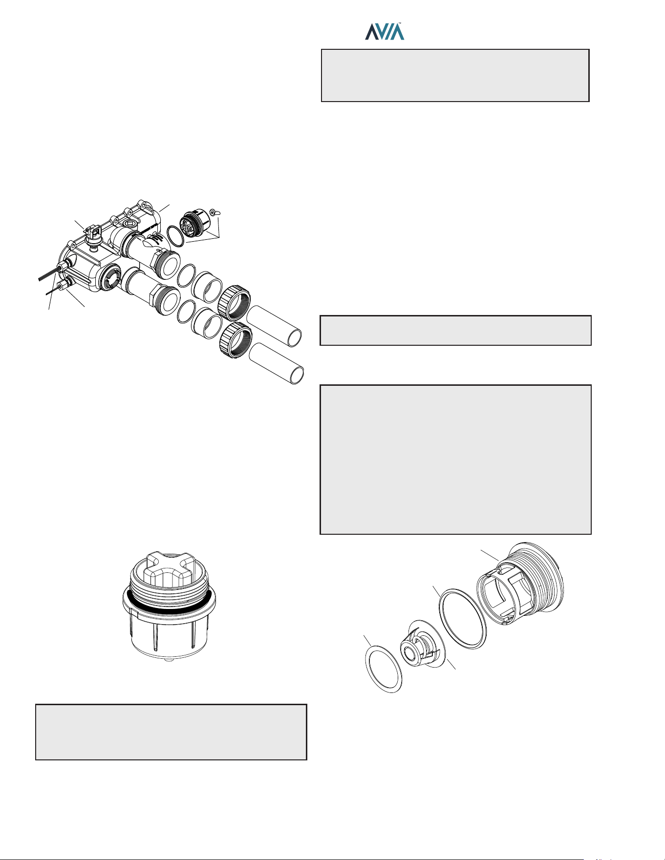
Unitherm Governor Operation
A
CAUTION: The patented Unitherm Governor is
a thermostatic mixing valve specically designed to
maintain constant heater internal temperature between
120°F (49°C) and 135°F (57°C) despite continually
changing ow rates from the lter and changing pool
temperatures. This range is needed to reduce the
amount of condensation from the n tubes which will
occur if the heater runs for any length of time below
100°F (38°C) water from the pool. It is also needed to
inhibit scale formation in the tubes by maintaining
temperatures well below accelerated scaling
temperatures.
GASKET
UNITHERM
GOVERNOR
UG PLUG
UG PLUG O-RING
Figure 19. Unitherm Governor
High-temperature CPVC header anges and header
ange nuts are provided. If there is any possibility of back-
siphoning when the pump stops, it is highly recommended
that a check valve (or valves) also be installed in the
system. It is also recommended to have a downstream ball
or gate valve to regulate heater ow and pressure.
Before attaching the 2-inch unions to the Inlet/Outlet
header, make sure the O-rings are properly seated in
the grooves. Use Aqualube or equivalent non-petroleum-
based lubricant on the O-ring. Hand tighten the unions.
Glue PVC piping directly to the unions.
OUTLET
WATER
SENSOR
WATER
PRESSURE
SWITCH
HEADER
INLET
WATER
SENSOR
PROTEK
SHIELD
ASSY
Figure 17. Inlet/Outlet Header
ProTek Shield Assembly
This heater is equipped with a ProTek Shield Assembly
located horizontally on the right side of the Inlet water
connection.
This component provides protection to the heat exchanger
against galvanic corrosion, when properly bonded to the
heat exchanger. It should be replaced when the weight of
the ProTek Shield is reduced to about 40% of the original
weight (1.46 lbs.).
F10715
Figure 18. ProTek Shield Assembly
A
CAUTION: STOP the pool pump before attempting
to remove ProTek Shield Assembly. Failure to do so may
result in damage to ProTek Shield Assembly, loss of pool
water, or personal injury.
21
INSTALLATION & OPERATION MANUAL
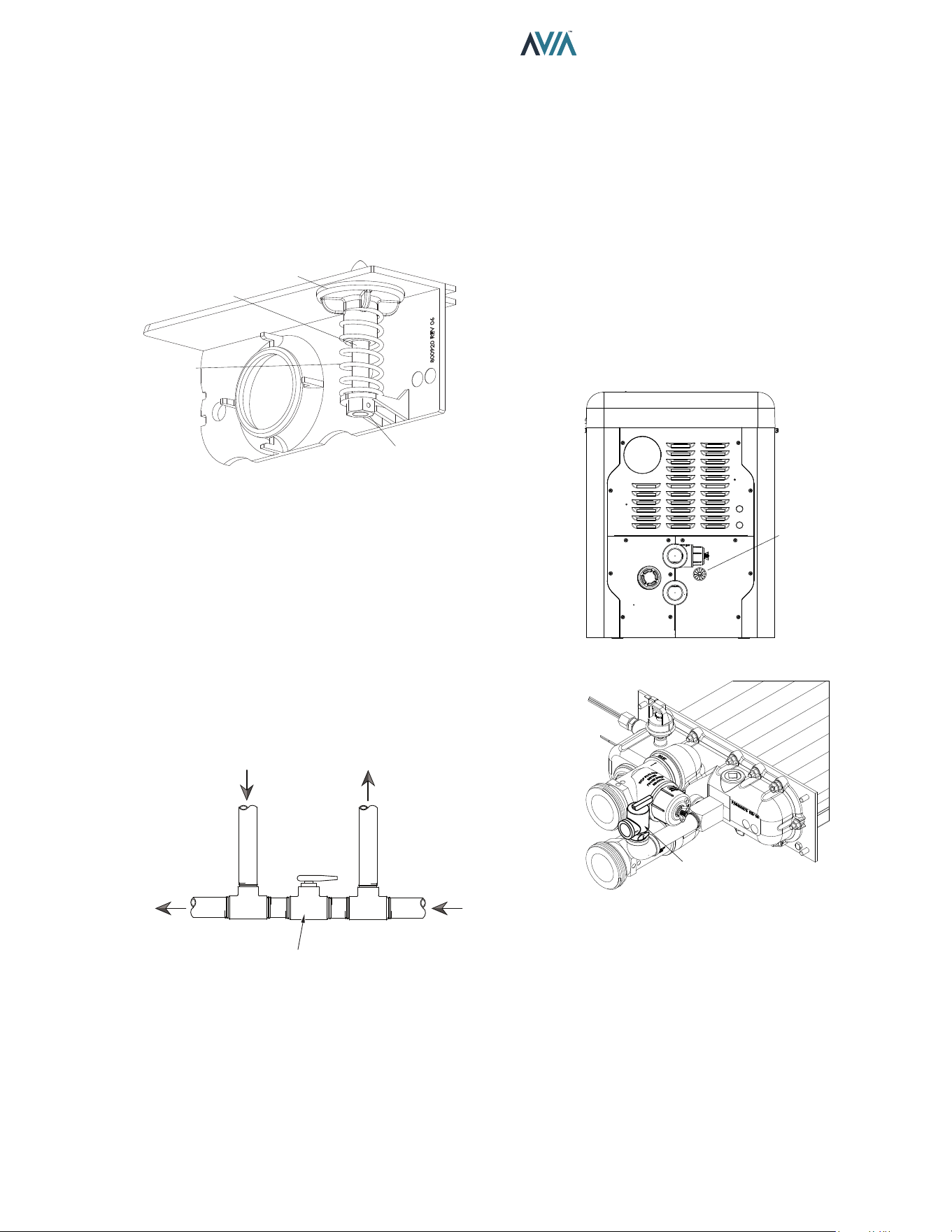
Internal Automatic Bypass Valve
In addition to the Unitherm Governor, a built-in automatic
bypass valve is provided in the Inlet/Outlet header. While
the Unitherm Governor responds to the changes in water
temperature in the heater, the internal bypass valve
automatically responds to changes in water pressure in the
piping system. Proper amount of water ow is maintained
through the heater under varying pressures dictated by the
conditions of the pump and lter.
BYPASS VALVE
BYPASS
SPRING
LOCK-NUT
BYPASS SHAFT
Figure 20. Internal Automatic Bypass Valve
External Auxiliary Bypass Valve
Where Required - An auxiliary bypass valve should be
used when ow rates exceed 100 GPM (379 lpm). Usually
a high-performance pump size larger than two horsepower
will exceed this ow rate. This valve is required to
complement the function of the automatic bypass valve,
particularly when starting the heater in winter or early
spring when the spa or pool temperature is below 50°F
(10°C). It also serves to eliminate needless pressure drop
through the heater and accompanying reduction in the ow
rate to the spa jets.
FROM HEATER
TO HEATER
TO POOL/SPA
FROM POOL/SPA
FULL PORT
BALL VALVE
OR GLOBE
VALVE*
BYPASS VALVE
*NOTE: Do not use a gate valve.
Figure 21. Auxiliary Bypass Valve
Auxiliary Bypass Valve Adjustment
To set bypass - With clean lter, adjustment is made by
feeling the inlet and outlet pipes at the heater. Outlet pipes
should be slightly warmer than inlet and comfortable to the
touch. If pipe is hot, close bypass; if cold, open bypass.
Pressure Relief Valve Installation
A 3/4" NPT connection is provided in the header for
installation of a pressure relief valve (PRV). The valve
shall be installed in a vertical position. The PRV can leak
overtime and may not operate correctly if installed in a
dierent orientation. Do not over-tighten. Install pressure
relief valve hand-tight, plus a 1/2 turn. Use Raypak PRV
kit (018936F) and Figure 23 below to properly plumb the
PRV.
ROUTE
PIPING
THROUGH
PORT
Figure 22. PRV Location
PRV VALVE
Figure 23. PRV Installed
22
INSTALLATION & OPERATION MANUAL
NOTE: To avoid water damage or scalding due to valve
operation, drain pipe must be connected to the outlet of
the PRV and run to a safe place of discharge. Drain pipe
must be the same size as the valve discharge connection
throughout its entire length and must pitch downward
from the valve. No shuto valve shall be installed
between the relief valve and the drain line. Valve lever
should be tripped at least once a year to ensure that
waterways are clear.
The heater requires water ow and positive pressure to
re and operate properly. It must therefore be installed
downstream of the discharge side of the lter pump. See
Figure 24 and Figure 25.
A typical installation is plumbed as follows:
1. The inlet side of the filter is plumbed directly to the
discharge side of the filter pump;
2. The outlet side of the filter is then plumbed to the inlet
of the heater; and
3. The outlet of the heater is plumbed to the return line
to the pool or spa. The pump, filter and heater are
thus plumbed in series (Salt generators and chemical
feeders must be downstream of the pool heater).
A
CAUTION: An additional source of heated water,
e.g. a solar heating system, must be connected to the
main line ahead of the heater inlet pipe in order for it
to act as the primary heat source. If the primary system
provides adequate heat to maintain setpoint, the heater
will not re. Be advised that the control panel will then
display sensed water temperatures downstream of the
primary heating system, rather than the temperature of
the water exiting the pool.
Heater must be located so that any water leaks will not
damage the structure of adjacent area. CPVC or PVC pipe
may be glued directly into the half-unions provided.
23
INSTALLATION & OPERATION MANUAL
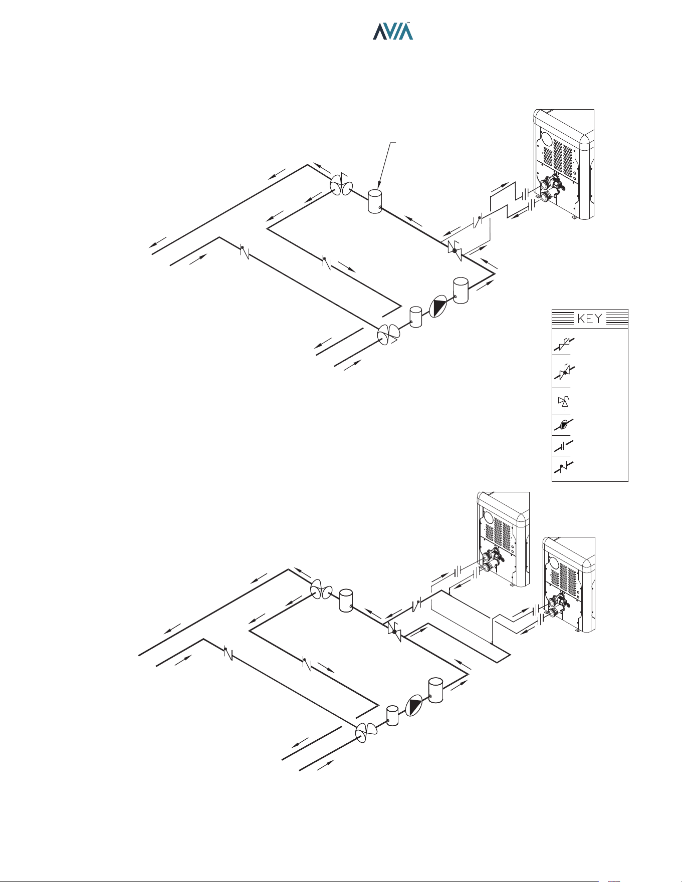
Plumbing Diagrams
Water Connections
VALVE SIDE A
CLOSED WHEN SYSTEM
IS HEATING THE POOL
CHEMICAL
INSERTION POINT
3-WAY VALVE
A
B
AB
TO SPA
FROM SPA
VALVE SIDE B
CLOSED WHEN SYSTEM
IS HEATING THE SPA
BYPASS
VALVE
COARSE
STRAINER
FILTER
PUMP
B
A
AB
VALVE SIDE B
OPEN WHEN SYSTEM
IS HEATING THE SPA
VALVE SIDE A
OPEN WHEN SYSTEM
IS HEATING THE POOL
TO POOL
FROM POOL
THIS DIAGRAM IS A RECOMMENDATION AND IS NOT INTENDED
TO REPLACE AN ENGINEERED PIPING SYSTEM BY A PROFESSIONAL ENGINEER
POOL HEATER
WITH
INTERNAL BYPASS
Figure 24. Single Pool Heater Installation
THIS DIAGRAM IS A RECOMMENDATION AND IS NOT INTENDED
TO REPLACE AN ENGINEERED PIPING SYSTEM BY A PROFESSIONAL ENGINEER
TO SPA
3-WAY
VALVE
FROM SPA
VALVE SIDE A
CLOSED WHEN SYSTEM
IS HEATING THE POOL
VALVE SIDE B
CLOSED WHEN SYSTEM
IS HEATING THE SPA
POOL HEATER
WITH
INTERNAL BYPASS
POOL HEATER
WITH
INTERNAL BYPASS
CHEMICAL
INSERTION POINT
TO POOL
FROM POOL
A
B
AB
BYPASS
VALVE
3-WAY
VALVE
B
A
AB
FILTER
PUMP
COARSE
STRAINER
VALVE SIDE B OPEN WHEN SYSTEM
IS HEATING THE SPA
VALVE SIDE A OPEN WHEN SYSTEM
IS HEATING THE POOL
Figure 25. Multiple Pool Heater Installation
ISOLATION
VALVE
PRESSURE
RELIEF VALVE
PUMP
UNION
CHECK VALVE
BALL VALVE
24
INSTALLATION & OPERATION MANUAL
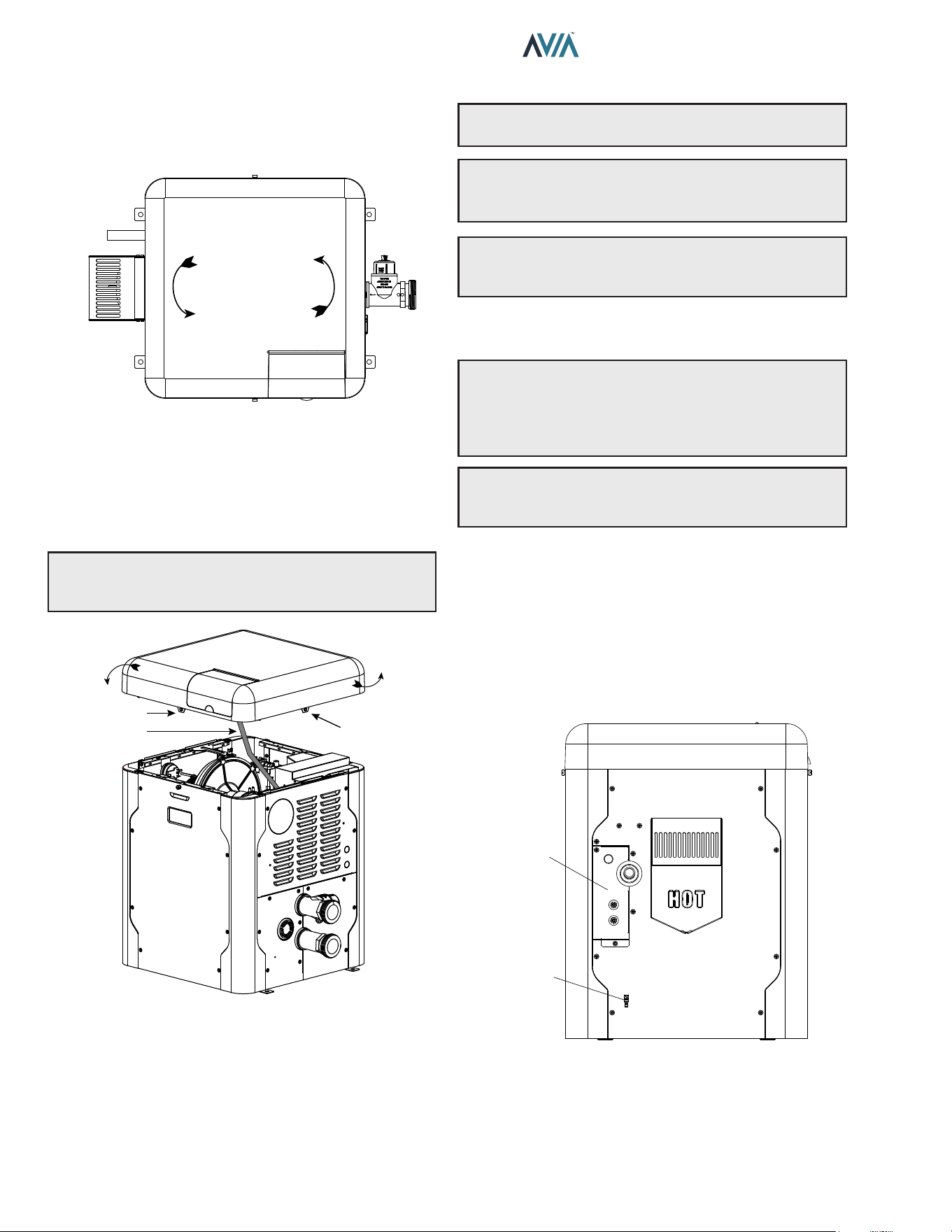
Water/Flue Connection Reversal
The heater is designed so that the control panel along with
the top can rotate in 90-degree increments to face the user.
90°
90°
Flue Connection
or Outdoor Cover
Display
Water
Connections
Figure 26. Connection Reversal
To rotate the top, remove the (2) knurled screws holding
the jacket top to the heater as shown below. Rotate the top
to the desired position and reinstall the knurled screws to
retain the jacket top. See Figure 34 on page 27.
NOTE: To prevent wire harness damage, ensure
harnesses are out of the way when handling the top
cover.
ROTATE
THE TOP
SCREW HOLE
CONTROLS
HARNESS
SCREW HOLE
Figure 27. Rotate Jacket Top
5. ELECTRICAL WIRING
NOTE: If it is necessary to replace any of the original
wiring, use 150°C wire or its equivalent.
A
WARNING: The heaters are factory-wired for 240
VAC, 1Ph, 60Hz power supply. DO NOT attempt to
operate at 208 VAC or below.
NOTE: Holes not utilized on jacket and electric junction
box, can be used for remote mode selector, Protégé VS
pump wiring, or auxiliary control interface.
Electrical Power Draw
A
CAUTION: A bonding lug is located below the
junction box. Failure to ground the heater electrically
could aect the heater's electronics. A Bonding Wire
must be installed as per NEC requirements to safeguard
persons and property.
NOTE: See "Time Clock/Fireman’s Switch" on page
38 for further instructions if using a time clock/
reman’s switch.
The Electronic Ignition Device automatically lights the
burner upon a call-for-heat. The heater is supplied with a
dual-voltage transformer for 120 VAC or 240 VAC input
power hookup. Factory default conguration is 240 VAC.
When using 120VAC, wire the transformer per Figure 29
and change the blower jumper per Figure 30.
When operating on 120 VAC power, units draw
approximately 1.6 amps. When operating on 240 VAC
power, units draw approximately 1.2 amps.
POWER
SUPPLY
BONDING
LUG
Figure 28. Heater Wiring Locations
25
INSTALLATION & OPERATION MANUAL
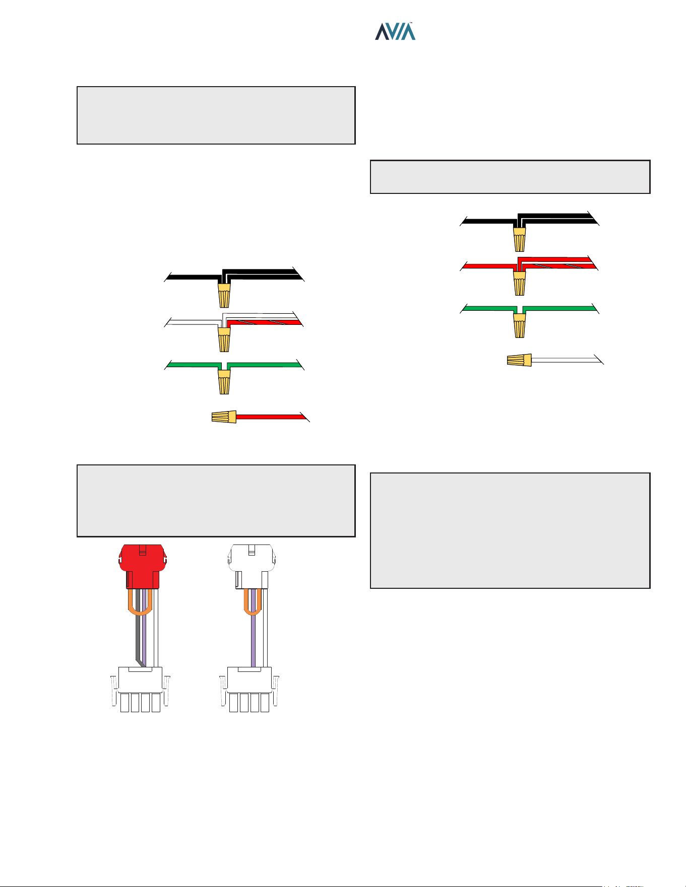
Transformer Wiring
CAUTION: If the transformer’s primary side is wired for
120 VAC and 240 VAC is applied, damage to the trans-
former and PC board may result. Such damages are not
covered under manufacturer’s limited warranty.
120 VAC Wiring
For 120 VAC input power to the unit, connect the eld-
supplied black wire (L1) to the (2) black wires from the
heater. Connect the white and red/white wires to the "N"
or Neutral leg of the power supply. There should be no
connection to the red wire for 120 VAC operation.
Attach a wire nut to the red wire.
RED
GREENGREEN
GROUND
RED & WHITE
WHITE
RETURN
NEUTRAL
WHITE
HEATER
6 WIRES
BLACK
BLACK
L1
HOT
BLACK
SUPPLY
SIDE
Figure 29. 120 VAC Wire Connection
CAUTION: The heater is pre-wired with a 240V
connector to the blower. If the supply voltage is 120V,
replace the connector with the supplied 120V (red
connector). Using the wrong corresponding connector
will cause electrical damage.
120V
240V
Figure 30. Blower Jumpers
240 VAC Wiring
For 240 VAC input power to the unit, connect the black
wires to the L1 or hot leg of the power supply. Connect
the red and red/white wires to the “L2” or second hot leg
of the power supply. There should be no connection to
the white wire for 240 VAC operation. Attach a wire nut
to the white wire.
A
WARNING: DO NOT attempt to operate the heater
at 208 VAC.
GREENGREEN
GROUND
RED & WHITE
RED
L2
HOT
RED
HEATER
6 WIRES
BLACK
BLACK
L1
HOT
BLACK
SUPPLY
SIDE
WHITE
Figure 31. 240 VAC Wire Connection
The heater must be electrically grounded and bonded in
accordance with local codes, or, in the absence of local
codes, with the latest edition of the National Electrical
Code, ANSI/NFPA 70. (Canada - Canadian Electrical
Code, CSA C22.1, Part 1 and Part 2.)
NOTE: Input power to the heater (120 or 240 VAC) can
be supplied from the load (pump) side of time clock or
directly from the GFCI power source. It is preferred that
full-time power be supplied to the heater from the GFCI
power source, and that the heater be controlled by the
reman’s switch connection or using a two or three-wire
remote. If using a switched GFCI power source, the heater
could display false service indicators on the display panel
if the pump is turned o.
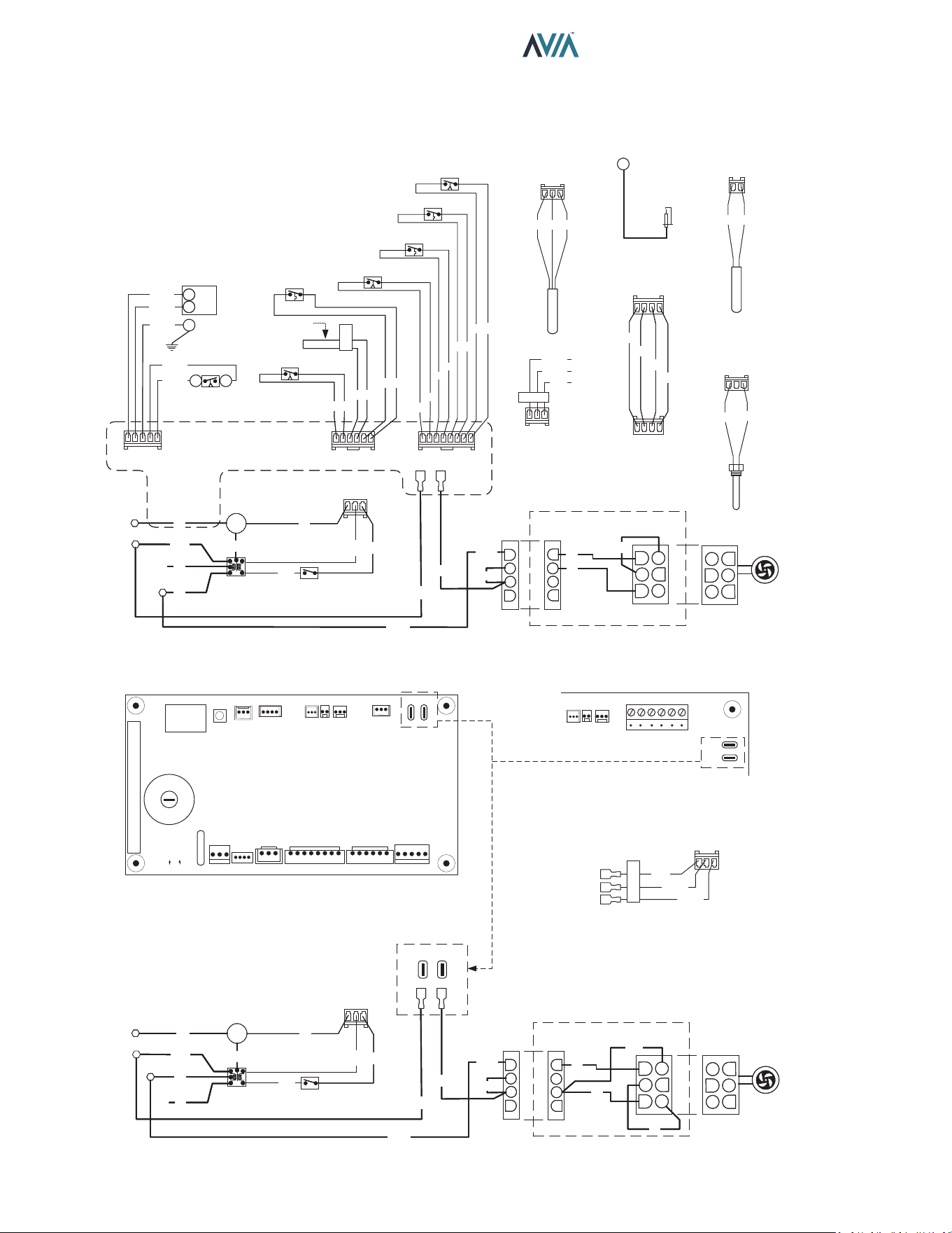
26
INSTALLATION & OPERATION MANUAL
6. CONTROLS WIRING DIAGRAM
240V AND 120V OPERATION
1
1
P7
P1
BR
BR/O
Y
BL
USER INTERFACE
1
1
P7
P1
BR
BR/O
Y
BL
USER INTERFACE
P1
GG
BK
1
INLET TEMPERATURE
SENSOR
P1
GG
BK
1
INLET TEMPERATURE
SENSOR
HIGH TENSION
T1
IGNITOR
HIGH TENSION
T1
IGNITOR
P2
RR
1
OUTLET TEMPERATURE
SENSOR
P2
RR
1
OUTLET TEMPERATURE
SENSOR
P3
BK
BK
1
VENT TEMPERATURE
SENSOR
P3
BK
BK
1
VENT TEMPERATURE
SENSOR
240V OPERATION
FEMALE
PLUG
MALE
PLUG
BK/W
BK/W
1
2
3
4
4
5
6
1
2
3
BLOWER
L1
SPG
GND
G
TRANSFORMER
24 VAC
POWER SWITCH
L2
P6
1
R
W
BK
G
G
BL
BL
Y
L1
SPG
GND
G
TRANSFORMER
24 VAC
POWER SWITCH
L2
P6
1
R
W
BK
G
G
BL
BL
Y
BK
R/W
R/W
MALE
PLUG
FEMALE
PLUG
240V JUMPER
1
2
3
4
1
3
4
5
6
W
V
22
O
240V OPERATION
FEMALE
PLUG
MALE
PLUG
BK/W
BK/W
1
2
3
4
4
5
6
1
2
3
BLOWER
L1
SPG
GND
G
TRANSFORMER
24 VAC
POWER SWITCH
L2
P6
1
R
W
BK
G
G
BL
BL
Y
BK
R/W
R/W
MALE
PLUG
FEMALE
PLUG
240V JUMPER
1
2
3
4
1
3
4
5
6
W
V
2
O
FLOW CHEM
VENT
TEMP
OUTPUT
TEMP
INTPUT
TEMP
AUX
POWER BLOWER
L
R
G
24V
SPA
POOL
WPS HL1 HL2 VNT
CAB CLK APS
DPS GV
F1
P6 P7 P8 P4A P4B P5
T1
P11 P12 P3 P2 P1 P9
RED GRAY
POWER BLOWER
UI
GND
GAS VALVE
DIFFERENTIAL
PRESSURE SWITCH
1
2
45
1
TH
TR
P5
V/BK
Y/BK
G/BK
R/BK
O/BK
3
CABINET
GND
GAS VALVE
DIFFERENTIAL
PRESSURE SWITCH
1
2
45
1
TH
TR
P5
V/BK
Y/BK
G/BK
R/BK
O/BK
3
CABINET
P4A
1
O
O/BK
GY
R
O
O
VENT PRESSURE SWITCH
HI TEMP LIMIT SWITCH #2
HI TEMP LIMIT SWITCH #1
WATER PRESSURE / FLOW
SWITCH
R
GY
P4B
1
BR BR
V V
W W
AIR PRESSURE SWITCH
SPLICE HERE FOR
CLOCK / FIREMAN
SWITCH
CABINET SWITCH
P4B
1
BR BR
V V
W W
AIR PRESSURE SWITCH
SPLICE HERE FOR
CLOCK / FIREMAN
SWITCH
CABINET SWITCH
SETUP
CUT A CUT B
REMOTE 3 WIRE
POOL
SPA
(24 VAC)
P8
1
BL
O/BK
BK/O
REMOTE 3 WIRE
POOL
SPA
(24 VAC)
P8
1
BL
O/BK
BK/O
NO
NC
NC
NC
NC
NC
NO
NO – Normally Open
NC – Normally Closed
POWER BLOWER
120V OPERATION
FEMALE
PLUG
MALE
PLUG
FEMALE
PLUG
MALE
PLUG
120V JUMPER
BK/W
BK/W
1
2
3
4
1
2
3
4
1
2
3
4
5
6
4
5
6
1
2
3
BLOWER
W
V
BK
O
L1
SPG
GND
G
TRANSFORMER
24 VAC
POWER SWITCH
Neutral
P6
1
R
W
BK
G
G
BL
BL
Y
L1
SPG
GND
G
TRANSFORMER
24 VAC
POWER SWITCH
Neutral
P6
1
R
W
BK
G
G
BL
BL
Y
BK
R/W
R/W
120V OPERATION
FEMALE
PLUG
MALE
PLUG
FEMALE
PLUG
MALE
PLUG
120V JUMPER
BK/W
BK/W
1
2
3
4
1
2
3
4
1
2
3
4
5
6
4
5
6
1
2
3
BLOWER
W
V
BK
O
L1
SPG
GND
G
TRANSFORMER
24 VAC
POWER SWITCH
Neutral
P6
1
R
W
BK
G
G
BL
BL
Y
BK
R/W
R/W
Factory installed
PCB 1134-83-7503/7603
BLOWER
POWER
VENT
TEMP
OUTPUT
TEMP
INTPUT
TEMP
P3 P2 P1
P9
NC2 NO2 C2 NC1 NO2 C2
PCB 1134-83-7506/7606
AUXILIARY OUTPUT
(with PCB 1134-83-7503)
NO
NC
COMMON
P9
1
BK/W
BK/R
BK
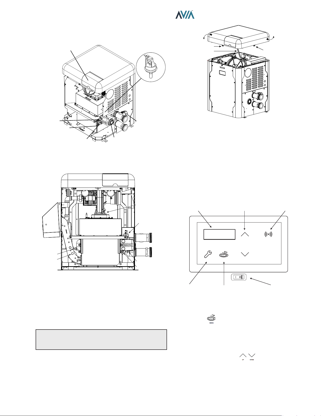
27
INSTALLATION & OPERATION MANUAL
7. CONTROLS
HL1 - HIGH TEMP. LIMIT
HL2 - HIGH TEMP. LIMIT
UNITHERM
GOVERNOR
PROTEK
SHIELD
ASSY
CONTROL
BEZEL
F108390-1
OUTLET SENSOR
INLET SENSOR
WATER
PRESSURE
SWITCH
F10671
Figure 32. Location of Controls (View One)
BLOWER
WATER PRESSURE
SWITCH
HIGH LIMIT (HL 2)
HIGH LIMIT (HL 1)
FLUE SENSOR
DRAIN PLUG IN
REAR HEADER
Figure 33. Location of Controls (View Two)
Heater Top Removal
1. Remove the knurled screws from front and rear door.
See Figure 34.
2. Lift top cover to detach from unit. Leave display
harness connected to ignition board.
NOTE: To prevent wire harness damage, ensure
harnesses are out of the way when handling the top
cover.
ROTATE
THE TOP
SCREW HOLE
CONTROLS
HARNESS
SCREW HOLE
Figure 34. Heater Top Removal
Control Adjustments
The pool heater touchpad, located on the upper front panel
of the heater, allows the user to select either POOL or SPA
operation, and to adjust the setpoint temperature. The LCD
display window indicates the mode (OFF, SPA, POOL)
and the actual water temperature. A manual power switch
provided below the touchpad turns the control power ON or
OFF. The LCD shows the control boards rmware versions
momentarily at power on. See Figure 35.
MODESERVICE
DOWN
UP
CONNECT
LCD DISPLAY TEMP ADJUST CONNECT MENU
SERVICE MENU MODE KEY
ON / OFF
SWITCH
Igni�on 1.20
UI 1.20
Figure 35. Control Adjustments
Mode Key
The Mode Key is used to select POOL or SPA operation. It
also allows the user to select the OFF mode of operation,
during which the LCD, while displaying OFF, continues to
show the water temperature.
UP and DOWN Keys
If the heater is in POOL or SPA mode, the desired water
temperature (SETPOINT) will be displayed and may be
adjusted using the UP or DOWN keys.
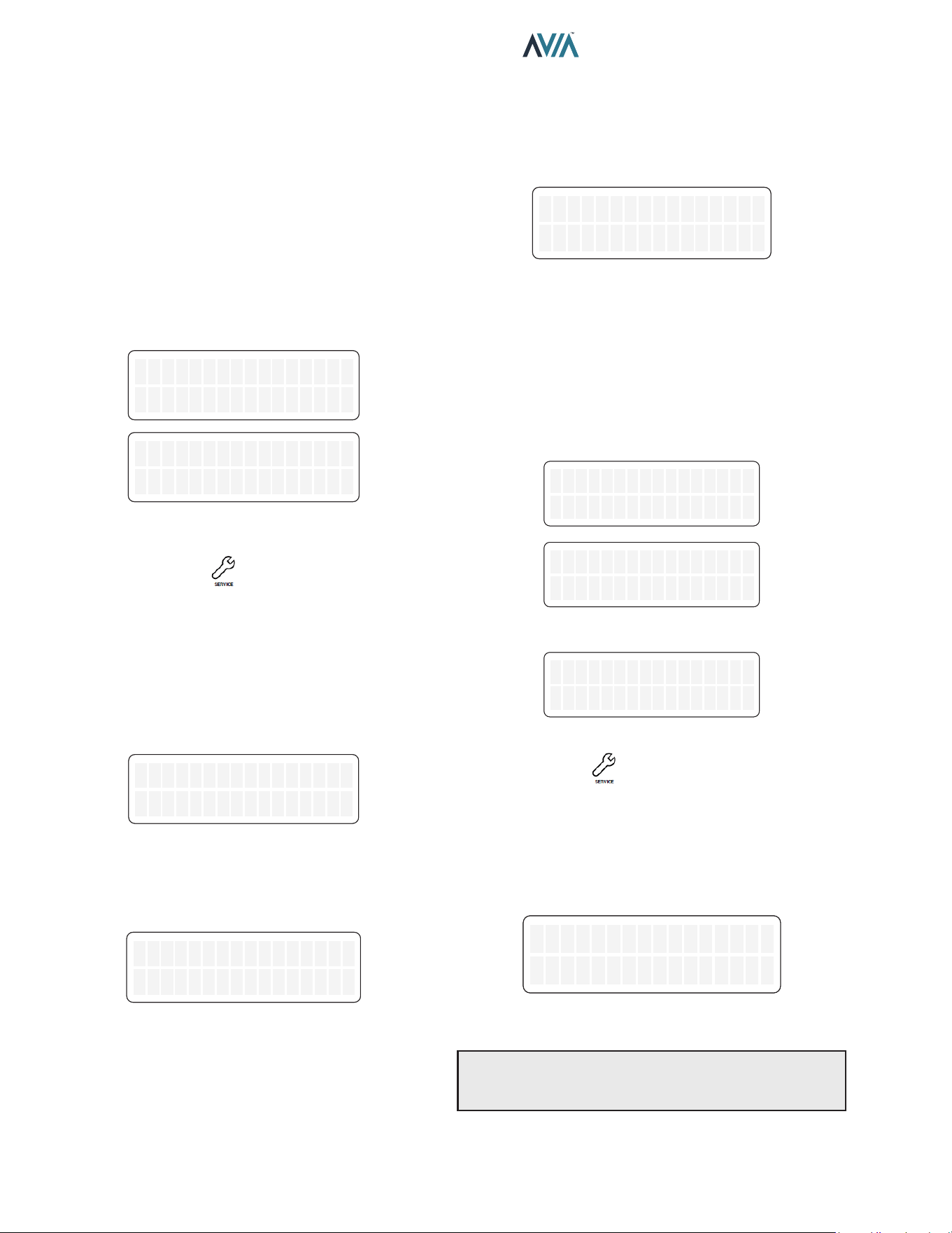
28
INSTALLATION & OPERATION MANUAL
Operation
In the POOL or SPA modes, the actual water temperature
is displayed along with the desired water temperature
(SETPOINT). When the water temperature is above the
setpoint, “Water Temp” will alternate with “No Demand.”
When the water temperature is below the setpoint and the
heater is ring, “Water Temp” will alternate with “Heating.”
To adjust the setpoint temperature, make sure the control
is in the appropriate mode (POOL or SPA) and touch the
UP or DOWN keys.
By default, the setpoint range is 50-104°F (10-40°C). See
"Program Menu" on page 31 to adjust the MAX setting,
if necessary.
OFF
Water Temp 68F
OFF
Water Temp 68F
OFF
No Demand
OFF
No Demand
Figure 36. Alternating Display During Heating
Service Menus
To access the Service Menu and fault history, press the
SERVICE key 1 time. The heater will continue to operate
while in the Service Menu.
The rst screen displayed is the Flame Strength indicator,
which indicates the ame current using a numerical display.
A signal of less than 1.0 μA indicates a weak ame signal
and may require service. Refer to "Troubleshooting" on
page 48 for possible causes and corrections.
Flame Strength
9.5uA
Flame Strength
9.5uA
Figure 37. Flame Strength Indicator
Press the DOWN key. The Supply Voltage screen indicates
the voltage supplied to the control board. Normal readings
range from 24 to 30 volts.
Supply Voltage
24V
Supply Voltage
24V
Figure 38. Supply Voltage Indicator
Press the DOWN key. The "Hours" run time indicates the
total hours of operation for the pool heater, as measured by
the amount of time that the gas valve has been powered.
The "Cycles" count indicates the number of on/o cycles of
the heater, as measured by the number of times the valve
has been powered.
Hours 451
Cycles 89
Hours 451
Cycles 89
Figure 39. Run Time/Cycles
Press the DOWN key. The Fault History displays up to ten
faults in memory. The order of the faults begins with "Last
Err" which is the most recent fault, and proceeds through
the ten most recent messages in reverse chronological
order. Run time hours at the moment of the fault are
displayed at the end of line one. The second line of the
display shows the fault message. If there are no faults in
the history buer, the second line reads “All Faults Clear.”
or
Last Err 0
All Faults Clear
Last Err 0
All Faults Clear
Fault 9 241
Ign 60 min Delay
Fault 9 241
Ign 60 min Delay
Last Err 450
Inlet Temp Fail
Last Err 450
Inlet Temp Fail
Figure 40. Fault History Indicator
Press the Service key again. The advance service
menu is accessed.
Inlet and Outlet Temperature
The Inlet / Outlet Temperature screen indicates the water
temperature sensed in the inlet and at the outlet of the heat
exchanger.
In/HX Out Temp
In 68F, Out 108F
In/HX Out Temp
In 68F, Out 108F
Figure 41. Inlet and Heat Exchanger Outlet Temperature
NOTE: Outlet temperature sensor is located before
the bypass valve. Outlet temperature readings do not
represent the pool system outlet temperature.
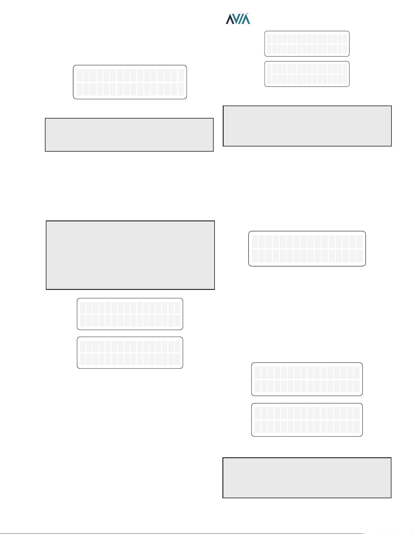
29
INSTALLATION & OPERATION MANUAL
Vent Temperature
Press the DOWN key. The Vent Temperature screen
indicates the temperature sensed in the vent.
Vent Temperature
285 F
Vent Temperature
285 F
Figure 42. Vent Temperature
NOTE: If the sensed ue temp exceeds 390°F (199°C),
the heater will shut down on a vent temperature fault. If
the sensed ue temp is less than 175°F (79°C), the unit
may condense.
Flow Monitoring
Press the DOWN key. By default, the Flow Monitoring
screen indicates the estimated ow when unit is heating.
When optional ow sensor is installed, this screen can be
congured to display ow sensor readings. See page 32
to congure the Flow Sensor input.
NOTE: Ideal water ow rate for a heater is 40 GPM or
higher.
The HX Flow Estimate only considers water ow
through the heat exchanger. Ideal ows through the heat
exchanger are:
• 264 BTU unit is 7 to 14 GPM
• 399 BTU unit is 10 to 19 GPM
HX Flow Es�mate
13 GPM
HX Flow Es�mate
13 GPM
Flow Sensor
45 GPM
Flow Sensor
45 GPM
Figure 43. Flow Monitoring
Estimated Volume and Heat Time
Press the DOWN key. The Pool Volume and Heat Time
screen indicates the estimated pool volume in gallons and
heat-up time in minutes.
Press the DOWN key again. The Spa Volume and Heat
Time screen indicates the estimated Spa volume in gallons
and heat-up time in minutes.
Any volume equal or below 3000 gallons is considered a
Spa, while any estimated volume above 3000 gallons is
estimated as Pool.
Pool Est 11500 gl
Heat Time 97 min
Pool Est 11500 gl
Heat Time 97 min
Spa Est 1000 gl
Heat Time 25 min
Spa Est 1000 gl
Heat Time 25 min
|
Figure 44. Estimated Volume and Heat Time
NOTE: Volume and heat time estimations are based
on single heater supplying a body of water of constant
volume. Multiple heaters, combined heat sources or
interconnection of multiple body of waters may cause
wrong calculations.
Protégé Pump Status
Press the DOWN key. When a Protége variable speed
pump is connected to the heater and communication
is enabled, the Pump Status screen indicates current
pump conguration.
By default, Pump Control is disabled. See page 32 to
select and congure Pump Control.
Pump Status
Speed2 1500 RPM
Pump Status
Speed2 1500 RPM
Figure 45. Pump Status
Auxiliary Output
Press the DOWN button. The Auxiliary Output screen
indicates current status of the auxiliary relay output.
For operation verication of the auxiliary relay, press
SERVICE and MODE keys simultaneously for 3-seconds
to toggle output state between ON and OFF.
AUX output works as a “switch” that can be turned On/O
with Raymote app online scheduler.
Auxiliary Output
OFF
Auxiliary Output
OFF
Auxiliary Output
ON
Auxiliary Output
ON
Figure 46. Auxiliary Relay Output
NOTE: Auxiliary output (port P9) is a dry contact output:
It requires external power supply to energize connected
devices. Do not connect directly to an application that
requires more than 3 Amps. For more details see Section
13, Auxiliary Control Output on page 81.
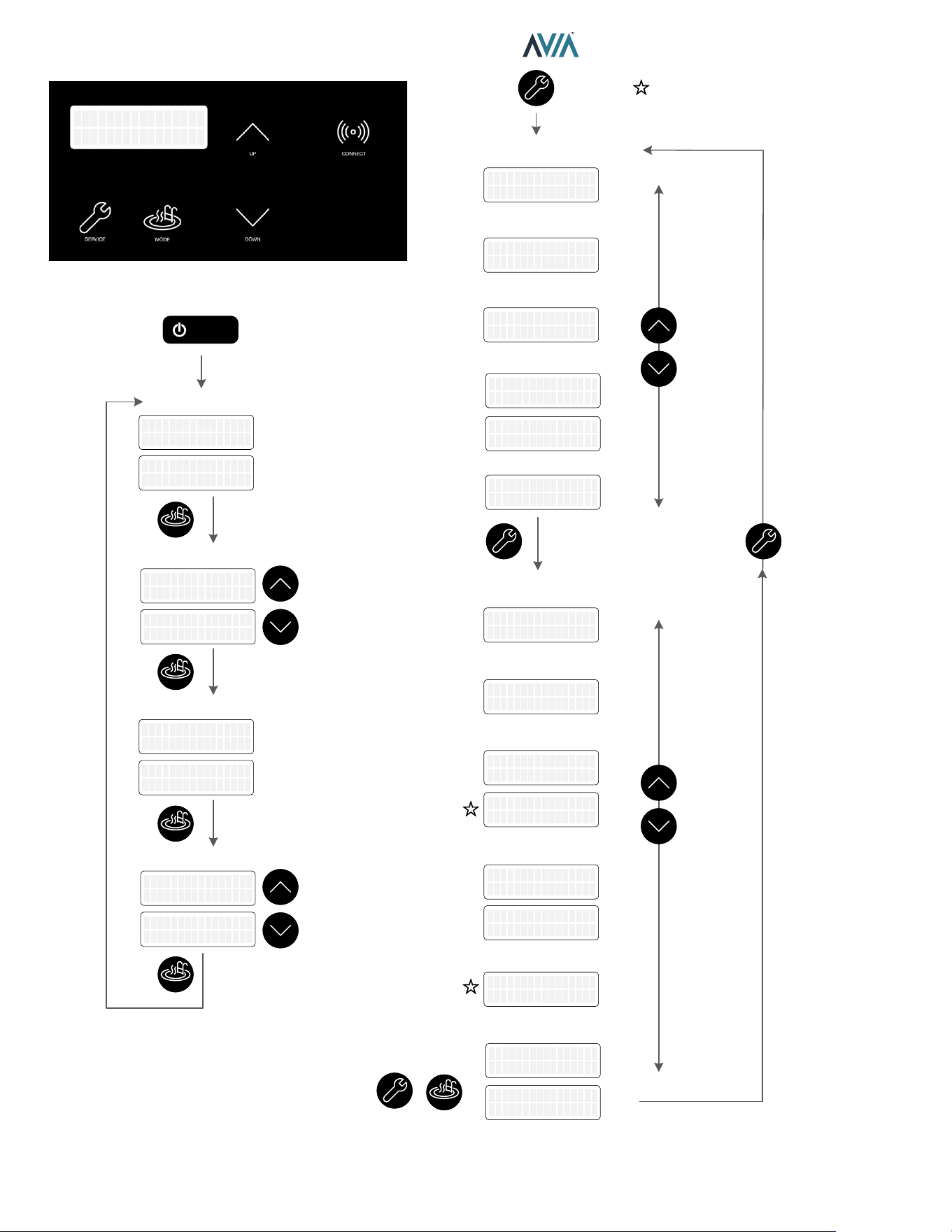
30
INSTALLATION & OPERATION MANUAL
OFF mode
PowerPower
SPA mode
OFF mode
POOL mode
Flame Strength
Supply Voltage
Run Counters
Faults History
Inlet/Outlet Temp.
Vent Temp.
Flow Monitoring
Protégé Pump Status
Volume & Heat Time
Adjust
Temperature
Adjust
Temperature
Aux Output
+
3 sec
Toggle ON/OFF
MODEMODE
MODEMODE
MODEMODE
MODEMODE
MODEMODE
UPUP
DOWNDOWN
UPUP
DOWNDOWN
UPUP
DOWNDOWN
UPUP
DOWNDOWN
Pool Set 85F
Water Temp 68F
Pool Set 85F
Water Temp 68F
OFF
Water Temp 68F
OFF
Water Temp 68F
OFF
No Demand
OFF
No Demand
SPA Set 90F
Water Temp 68F
SPA Set 90F
Water Temp 68F
SPA Set 91F
Hea�ng
SPA Set 91F
Hea�ng
OFF
Water Temp 68F
OFF
Water Temp 68F
OFF
No Demand
OFF
No Demand
Pool Set 85F
Hea�ng
Pool Set 85F
Hea�ng
Pool Est 11500 gl
Heat Time 97 min
Pool Est 11500 gl
Heat Time 97 min
Pump Status
Speed2 1500 RPM
Pump Status
Speed2 1500 RPM
HX Flow Es�mate
13 GPM
HX Flow Es�mate
13 GPM
Flow Sensor
45 GPM
Flow Sensor
45 GPM
Vent Temperature
285 F
Vent Temperature
285 F
In/HX Out Temp
In 68F, Out 108F
In/HX Out Temp
In 68F, Out 108F
Hours 451
Cycles 89
Hours 451
Cycles 89
Supply Voltage
24V
Supply Voltage
24V
Flame Strength
9.5uA
Flame Strength
9.5uA
Available in some configura�ons
and kits
Spa Est 1000 gl
Heat Time 25 min
Spa Est 1000 gl
Heat Time 25 min
Auxiliary Output
OFF
Auxiliary Output
OFF
Auxiliary Output
ON
Auxiliary Output
ON
or
Last Err 0
All Faults Clear
Last Err 0
All Faults Clear
Fault 9 241
Ign 60 min Delay
Fault 9 241
Ign 60 min Delay
Last Err 450
Inlet Temp Fail
Last Err 450
Inlet Temp Fail
Figure 47. Operation and Service Screens
31
INSTALLATION & OPERATION MANUAL
Program Menu
To access PROGRAM menu, press and hold SERVICE
and MODE keys simultaneously for 5 to 7-seconds until
"Language" appears on the display.
NOTE: Changes to default program congurations
could aect normal functionality of the heater.
Press the SERVICE key sequentially until the desired
program event is reached. By default, there are 12 dierent
settings that can be programmed. Additional congurations
for other add-ons are displayed when enabled. Figure 48
lists the default menus.
Set Defaults Defaults Set
Reset Faults Faults Cleared
Temp Display
Fahrenheit
Temp Display
Celsius
Spa Max Temp
50 F
Spa Max Temp
107 F
Pool Max Temp
107 F
WiFi Reset
Automa�on Mode
Enabled
Automa�on Mode
Disabled
Flow Monitoring
Es�ma�on
Flow Monitoring
Flow Sensor
Al�tude Normal
0 to 4500 �
Al�tude High
Above 4500 �
WiFi Ini�alized
Pool Max Temp
50 F
Pump Control
Disabled
Pump Control
Enabled
Water Chemistry
Disabled
Water Chemistry
Enabled
Langue
Français
Langue
Français
Lenguaje
Español
Lenguaje
Español
Language
English
Language
English
Figure 48. Programmable Settings
Language Selection
Initial display in PROGRAM Menus is "Language"
selection.
The UP and DOWN keys will select English, Spanish or
French language for all menus and Display messages.
Set Factory Defaults
Press the SERVICE key again. "Set Defaults" option is
displayed. To set factory defaults, press and hold SERVICE
and MODE keys simultaneously for 3 to 5-seconds until
"Defaults Set" appears.
This operation resets the operating program to its factory
default values.
Both the POOL and SPA setpoints will revert to 65°F
(18°C) and both POOL and SPA maximum temperature
settings will be 104°F (40°C). Language is set to English,
temperature display is set to Fahrenheit, Automation Mode
is enabled, Altitude to Normal, Flow monitoring is set to
Estimate, Protége Pump Control and other add-ons are
disabled. The Control Lockout PIN will be cleared and
the control will resume normal operation. See "Control
Lockout" section on page 34.
Reset Faults
Press the SERVICE key again. "Clear Faults" appears
on the digital display. To clear fault history press and
hold SERVICE and MODE keys simultaneously for 3 to 5
seconds until "Faults Cleared" appears.
Temperature Display
Press the SERVICE key again. "Temp Display" appears
on the digital display. The UP or DOWN keys will select
Fahrenheit or Celsius on the temperature display. Choose
the desired temperature scale.
Spa Setpoint Maximum Adjustment
Press the SERVICE key until "Spa Max. Temp" appears
on the digital display. Using the UP and DOWN keys will
change the Maximum Temperature Setting to your desired
value. The control can be set for a maximum of 107°F
(42°C).
Pool Setpoint Maximum Adjustment
Press the SERVICE key until "Pool Max. Temp" appears
on the digital display. Using the UP and DOWN keys will
change the Maximum Temperature Setting to your desired
value. The control can be set for a maximum of 107°F
(42°C).
WARNING: Ensure to properly setup pool and spa
maximum setpoint limits. Setpoint should never exceed
above 107° F (42°C).
32
INSTALLATION & OPERATION MANUAL
Wi-Fi Reset
Press the SERVICE key again. "Wi-Fi Reset" appears
on the digital display. To clear stored Wi-Fi signal name
and password, press and hold SERVICE and MODE keys
simultaneously for 3 to 5-seconds until "Wi-Fi Initialized"
appears.
This operation resets the Wi-Fi credentials, leaving the unit
ready to congure connection with the Raymote app. For
details on how to connect your pool heater to Raymote,
follow the instructions on page 51.
Automation Mode
Press the SERVICE key until "Automation Mode" appears
on the digital display. The UP or DOWN keys will select
Enabled or Disabled Automation mode functionality.
When Automation is disabled, Raymote online-scheduled
routines are ignored.
By default, Automation Mode is enabled. For details on
how to congure scheduling and automation with Raymote,
refer to page 63.
Flow Monitoring
Press the SERVICE key until "Flow Monitoring" appears
on the digital display. The UP or DOWN keys will select
"Estimation" or "Flow Sensor" on the Flow Monitoring
function.
By default, Flow Monitoring is set to "Estimated". This
function estimates the ow through the heat exchanger
when unit is in "Heating" status.
Flow Sensor input port (P11) is compatible with an optional
5 VDC hall-eect Flow Sensor. When Flow Sensor option
is enabled, the ow sensor input (P11) translates a pulse
count of 1 Hz to 1 GPM. To calibrate, set a gain using the
Flow Sensor Gain sub-menu.
Sensor Gain 1.0
Flow 2 GPM
Sensor Gain 1.0
Flow 2 GPM
Sensor Gain 12.5
Flow 25 GPM
Sensor Gain 12.5
Flow 25 GPM
Figure 49. Submenu – Flow Sensor Gain
Protégé Pump Control
Press the SERVICE key until "Pump Control" appears
on the digital display. The UP or DOWN keys will select
"Enabled" or "Disabled". By default, Pump Control option
is Disabled.
Pump Control is compatible with Raypak Protégé VSP and
EVP variable speed pumps.
When "Pump Control" is enabled, the speed conguration
sub-menus are displayed. Use these sub-menus to set up
the 4-speed pump settings.
Pump Speed1
900 RPM
Pump Speed2
1500 RPM
Pump Speed3
2500 RPM
Pump Speed4
2900 RPM
Figure 50. Submenu – Pump Speeds
Water Chemistry
By default, Water Chemistry is "Disabled". Keep this setting
disabled to avoid related fault messages.
Auxiliary Mode
NOTE: This option is available only for units equipped with
2 Auxiliary relays (Control rmware 3.00).
Press the SERVICE key until "Auxiliary 1 Mode" or
"Auxiliary 2 Mode" appears on the digital display. The
UP or DOWN keys will select the operation mode of the
Auxiliary relays. The default mode is "Raymote/Manual"
for Auxiliary 1 and 2.
Use UP or Down key to change operation mode selection.
These are the operation modes available for the Auxiliary
outputs:
-Raymote/Manual: The Auxiliary output can be
commanded from Raymote or from the LCD Service menu.
-Spa mode: The Auxiliary turns ON while the heater is in
Spa mode.
-Pool mode: The Auxiliary turns ON while the heater is in
Pool mode.
-Pool/Spa mode: The Auxiliary turns ON while the heater
is in Pool or Spa mode.
-Blower mode: The Auxiliary turns ON while Blower is On.
-Heat mode: The Auxiliary turns ON while heater is in
Heat status mode.
Auxiliary 1 Mode
Raymote / Manual
Auxiliary 1 Mode
Raymote / Manual
Auxiliary 2 Mode
Switch w/ Blower
Auxiliary 2 Mode
Switch w/ Blower
Figure 51. Auxiliary Modes - 2-Aux Boards only
33
INSTALLATION & OPERATION MANUAL
+
5 sec
PROGRAM Menu
Set Defaults
Reset Faults
Temperature Display
Max Spa Setpoint
Max Pool Setpoint
WiFi Reset
OFF Spa OFF Pool
Opera�on Mode
Automa�on Mode
Flow Monitoring
Pump Control
Water Chemistry
Flow Gain
MODEMODE
UPUP
DOWNDOWN
MODEMODE
+
3 sec
MODEMODE
+
3 sec
MODEMODE
UPUP
DOWNDOWN
UPUP
DOWNDOWN
UPUP
DOWNDOWN
UPUP
DOWNDOWN
UPUP
DOWNDOWN
UPUP
DOWNDOWN
UPUP
DOWNDOWN
Defaults SetDefaults Set
Faults ClearedFaults Cleared
Temp Display
Fahrenheit
Temp Display
Fahrenheit
Temp Display
Celsius
Temp Display
Celsius
Spa Max Temp
50 F
Spa Max Temp
50 F
Spa Max Temp
107 F
Spa Max Temp
107 F
Pool Max Temp
50 F
Pool Max Temp
50 F
Pool Max Temp
107 F
Pool Max Temp
107 F
WiFi ResetWiFi Reset
WiFi Ini�alizedWiFi Ini�alized
Automa�on Mode
Enabled
Automa�on Mode
Enabled
Automa�on Mode
Disabled
Automa�on Mode
Disabled
Flow Monitoring
Es�ma�on
Flow Monitoring
Es�ma�on
Flow Monitoring
Flow Sensor
Flow Monitoring
Flow Sensor
Pump Control
Disabled
Pump Control
Disabled
Pump Control
Enabled
Pump Control
Enabled
Al�tude Normal
0 to 4500 �
Al�tude Normal
0 to 4500 �
Al�tude High
Above 4500 �
Al�tude High
Above 4500 �
Reset FaultsReset Faults
Sensor Gain 12.5
Flow 22 GPM
Sensor Gain 12.5
Flow 22 GPM
Water Chemistry
Disabled
Water Chemistry
Disabled
Water Chemistry
Enabled
Water Chemistry
Enabled
Set DefaultsSet DefaultsSet DefaultsSet DefaultsSet Defaults
Available in some
configura�ons and kits
Al�tude
UPUP
DOWNDOWN
Language
UPUP
DOWNDOWN
Language
English
Language
English
Lenguaje
Español
Lenguaje
Español
Langue
Français
Langue
Français
Auxiliary Modes
UPUP
DOWNDOWN
Automa�on Mode
Enabled
Automa�on Mode
Enabled
Automa�on Mode
Disabled
Automa�on Mode
Disabled
Figure 52. Program Menu Screens
34
INSTALLATION & OPERATION MANUAL
Control Lockout
The heater is equipped with a Control Lockout feature
to prevent unauthorized tampering or adjustment of the
control settings. To lock out the controls, press the MODE
and DOWN keys simultaneously for 5-seconds. Choose
a three-digit PIN, using the UP and DOWN keys to select
the digits and the MODE key to lock in selections. Conrm
your selection and record your PIN.
Control Lockout
Enter PIN 000
Confirm Lockout
Yes
Figure 53. Control Lockout
To unlock the controls, press MODE, UP or DOWN key
to bring up the ENTER PIN menu. Enter the PIN that
was used to lock the control. Note that power cycling will
not clear the lockout. Successfully unlocking the control
will display "LOCKBOX CLEARED". Failure to enter the
correct PIN will display "INVALID PIN".
In the event that the user-selected PIN is lost or does not
clear the Control Lockout, use the Program Menu to SET
FACTORY DEFAULTS. This will clear the PIN and allow
normal operation and selection of a new PIN if desired.
See the "Program Menu" section on page 31 for details.
NOTE: By setting FACTORY DEFAULTS, both the POOL
and SPA setpoints will revert back to 65°F (18°C) and the
POOL and SPA maximum temperature settings will be
104°F (40°C). These setpoints will need to be readjusted
to desired settings. Other default congurations are also
applied.
Status and Diagnostics
The LCD displays a variety of status and diagnostic
messages, depending on the operating conditions.
The following status messages are displayed in Pool,
Spa, and Remote modes when there are no active fault
conditions.
Display Condition
No Demand
Water temperature is equal or above
setpoint.
Verifying
Water
2-min wait for water pressure/ow
Pre-Purge Call-for-heat established.
Spark Spark operating.
Heating Flame present. Unit is heating.
Post-Purge Heating is terminated. Unit cool down.
Table O. Heater Status Messages
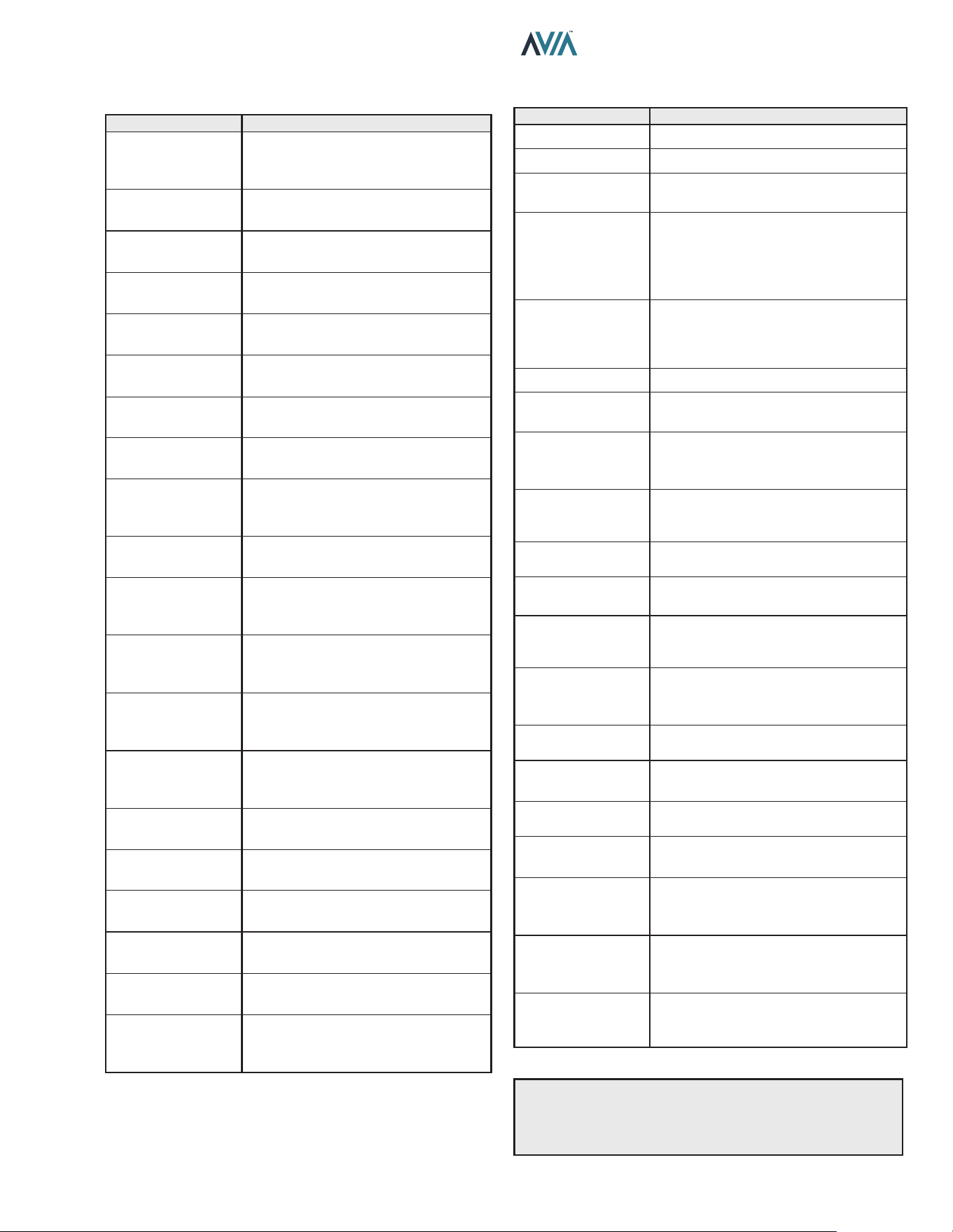
35
INSTALLATION & OPERATION MANUAL
The following conditions are displayed only while there is a
demand for heat present.
Display Condition
Flame Lost Flame was not detected when heating.
Water Sw Open Water pressure switch open.
Vent Sw Open
Vent air switch open. Check for vent
obstructions.
Hi Limit 1 Fault
High-Temp. limit 1 open. High limit fault
is auto recovery. For board rmware
1.10 and 2.10: Press MODE key to
remove lockout. Check water ow and
pump operation.
Hi Limit 2 Fault
High-Temp. limit 2 open. High limit fault
is auto recovery. For board rmware
1.10 and 2.10: Press MODE key to
remove lockout. Check water ow.
Cabinet Temp Lm Cabinet Temp. limit open.
Air SW Open
Air pressure switch open. Check air
inlet obstruction.
Fan Lockout
3 air switch faults within same heat
demand cycle. Power must be cycled
to clear the fault.
Di Sw Fault
Dierential Pressure switch failed
open. Check fan operation and main
power supply.
Ign Try Failure
Unit failed to ignite on rst or second
try. Check gas supply.
Ign 60 min Delay
Gas valve failed 3 times in single call-
for-heat. Unit is locked out for 60-min.
Ignition Lockout
When available, Single-try ignition
failed and Lockout. Power must be
cycled to clear the fault.
Flue Over Temp
Flue temperature was higher than
390°F (199°C). Power must be cycled
to clear the fault.
Remote Wire Err
While Remote mode is active, both
Spa and Pool inputs are energized.
Outlet Over Temp
Outlet Temp was higher than 180°F
(82.0°C). Check water ow.
Low Flow Fault
Low ow conditions are detected in the
heater. Possible scaling.
High Flow Fault
High ow conditions are detected in
the heater. Possible condensation.
Flue Low Temp
Flue temperature is below 175°F
(79.5°C). Warning: Possible
condensation.
Flue Extreme Low
Flue temperature is below 140°F (60
°C). Service required. Press MODE to
remove lockout.
Call Service
Recurrent faults reported. Heater, gas,
vent and water systems may need
attention. Contact Service support.
Table Q. Heater Status Messages - Demand for Heat
The following conditions are displayed in Pool, Spa and
Remote modes when there are active fault conditions.
Display Condition
No
Communication
With Ignition
Unable to communicate User
Interface with Ignition board. Check
P7 and harness wires.
In Sensor Fault
Water Inlet thermistor temperatures
disagree by more than 3°F (1.5°C).
In Sensor Open
Water Inlet thermistor sensor failed
open. Below 6°F (-14°C).
In Sensor Short
Water Inlet thermistor sensor failed
short. Above 188°F (86.5°C).
Out Sensor Open
Water Outlet thermistor sensor failed
open. Below 6°F (-14°C).
Out Sensor Short
Water Outlet thermistor sensor failed
short. Above 188°F (86.5°C).
Flue Sensor Open
Flue temp sensor failed open. Above
464° F (240°C).
Flue Sensor Shrt
Flue temp sensor failed short. Below
7.5°F (-13.5°C).
Flow Sensor Fail
When equipped, Flow sensor
readings are out of range (0 to 100
GPM).
Flame w/o CFH
Board is sensing ame when gas
valve is commanded shut.
Gas Valve Fault
Gas valve is sensed to be ON when
commanded OFF. 60-min. soft
lockout.
Pump Ctl Fail
When equipped, Protégé Variable
Speed Pump Control is enabled but
not responding to commands.
WChem Brd Fail
When available, disable WChem
setting in "Program" menu to clear
this fault.
Di Sw Closed
Control is sensing Dierential
pressure switch closed when Fan is
not commanded.
Di Sw Open
Fan is commanded for 10-seconds
without dierential switch closing.
Internal Fault or
EEPROM Fault
Memory fault. Reset setpoints or
replace board if fault does not clear.
Clock/Fireman Sw
Time clock/reman switch circuit is
open.
Low Temp
Lockout
Water temperature is below 36°F
(2°C).
Low Voltage
Controller is receiving supply voltage
below 23 VAC.
Sensor Misplaced
Check inlet and outlet sensor
installation. Check piping and pump
operation.
Table P. Heater Status Messages - Active Faults
See Troubleshooting guides on pages 49 and 50
for diagnosis.
NOTE: "Call Service" fault is auto-recovery after 60 min.
lockout. For control rmware 1.10 and 2.10: Press and
hold SERVICE key for 15-20 sec. Follow the instruction
in the LCD to clear "Call Service" fault.
36
INSTALLATION & OPERATION MANUAL
A
WARNING The ability to properly perform service on
this equipment requires certain expertise, mechanical
skills, tools, and equipment. If you do not possess
these, do not attempt to perform any service on this
equipment other than those procedures recommended
in this Manual.
Remote Mode Selector - Installation
and Operation
A
CAUTION: Before installing remote controls
to the heaters, read the following: The Heater is
remote-ready. The digital display shows the actual pool
temperature, operating status, and service messages.
See Figure 54. The touch keys on the control panel allows
you to select the desired pool or spa temperature. It also
indicates when a remote system is controlling the heater
by displaying Remote in the display. When connecting
the heater to a remote system, identify whether it is a
two- or three-wire remote system. Select the appropriate
instruction listed below to properly install the remote to
the heater.
Remote Mode Selector
The heaters are equipped with the ability to work with
external remote controls and automation systems. The
supplied 3-pin remote wiring connector supplies power
out to either a toggle switch or the switch contacts of a
third-party remote. The remote works by either making or
breaking the circuit created by the remote wiring. Typically,
a remote does not supply power to the heater, it only
provides a switching function to turn the heater On or O.
If your remote is supplying its own voltage to the heater, it
will not work with this heater and may damage the digital
circuit board.
For operation of the heater using the on-board thermostatic
controls with a time clock see "Time Clock/Fireman’s
Switch" section on page 38.
Remote OFF
Water Temp 68F
Remote OFF
Water Temp 68F
Remote OFF
No Demand
Remote OFF
No Demand
REMOTE MODE ENABLED
Remote Pool 85F
Water Temp 85F
Remote Pool 85F
Water Temp 85F
Remote SPA 90F
Water Temp 68F
Remote SPA 90F
Water Temp 68F
Remote SPA 90F
Heating
Remote SPA 90F
Hea�ng
Remote Pool 85F
No Demand
Remote Pool 85F
No Demand
Figure 54. Operation Modes
Activating the Remote
To activate or deactivate the remote function, press and
hold the UP and DOWN arrow keys simultaneously for 3
to 5-seconds.
The rst line in the LCD displays "Remote" and "O", "Pool"
or "Spa" and the temperature setpoint. The second line
of the LCD displays "Water Temp" and water temperature
alternating with heater status message. See page 34.
NOTE: When in remote operation, the keypad mode and
temp buttons are disabled.
Remote Control Wiring
ATTENTION
OBSERVE PRECAUTIONS
ELECTROSTATIC
SENSITIVE DEVICES
A
CAUTION: Electrostatic Discharge (ESD) damage
can be caused by direct or indirect contact with the
wiring or circuit board. When one walks to the heater
area, an electrostatic charge accumulates on the body.
Contact of a nger allows the body to discharge, possibly
causing device damage. This damage can be limited if
the service person discharges himself, following ESD
preventive/removal practices, and holds on to the heater
enclosure for 5-seconds before proceeding.
Important Installation Notes for Remote or External
Wiring Conguration:
• Remote wiring must be run in a separate conduit.
• Remote wiring must not be run parallel to high voltage
lines.
• For runs of under 30' (9 m), remote wiring should
have stranded conductors with a minimum of 22
AWG, 600V, cable twisting 1.5" to 2.5" (3.8 to 6.4 cm)
lay and jacketed.
• For runs over 30' (9 m), the conductors should be a
minimum of 20 AWG, 600V, cable twisting 1.5" to 2.5"
(3.8 to 6.4 cm) lay that is shielded and jacketed.
• Maximum cable length is 200' (61 m).
• For both two- and three-wire remote systems, the
provided 3-pin wiring connector must be utilized.
NOTE: The remote wires must be connected to the
3-wire remote interface harness before the connector is
plugged into the board.
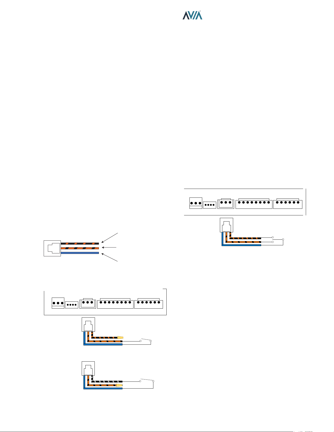
37
INSTALLATION & OPERATION MANUAL
2-Wire Remote Control (On-O)
This application assumes that only one heating function
(pool or spa) is required.
1. Turn on power to the heater.
2. For a 2-Wire Remote Control from a remote controller
without its own sensor, push the MODE key to the
“POOL” or “SPA” mode and set the desired setpoint
(e.g.102°F (39°C) for Spa).
3. For a 2-Wire Remote Control from a remote controller
with its own sensor, push the MODE key to select
“POOL” or “SPA” mode and set the temperature to
the highest setting available on the control. The actual
setpoint will be controlled by the remote controller.
4. Turn the MODE button to "OFF" and remove power
from the heater.
5. On the “Remote Interface Harness”, connect the
BLUE wire to one side of the “REMOTE” switch and
connect the other side to either the ORANGE/BLACK
wire for “SPA” operation or the BLACK/ORANGE wire
for “POOL” operation. See Figure 57.
6. Attach wire nut on the unused wire to the “Remote
Interface Harness.”
7. Install the “3-wire Remote Control Harness” to the P8
connector and turn power "ON" to the heater. See
Figure 57.
SET POOL
(BLACK WITH ORANGE)
SET SPA
(ORANGE WITH BLACK)
24VAC
(BLUE)
Figure 55. 3-Wire Remote Interface Harness
BLUE - 24VAC OUTPUT
REMOTE SPA
SWITCH
WIRE NUT BK/ORN
SPA MODE
SELECTOR
OR
POOL MODE
SELECTOR
REMOTE POOL
SWITCH
L
R
G
24V
SPA
POOL
WPS HL1 HL2 VNT
CAB CLK APS
P6 P7 P8 P4A P4B
BLUE - 24VAC OUTPUT
WIRE NUT ORN/BK
Figure 56. 2-Wire Remote Harness Installation
3-Wire Remote Control Using Three-
Position Selector (Pool-O-Spa, or Low-O-
High)
This application assumes that both heating functions (pool
and spa) are required.
1. Turn on power to the heater.
2. Push the MODE key to the “POOL” or “SPA” mode
and set the desired temperature for each (e.g. 80°F
(27°C) for Pool and 102°F (39°C) for Spa).
3. Turn the MODE key to "OFF" and remove power from
the heater.
4. On the 3-wire “Remote Interface Harness” connect
the BLUE wire to one side of the “REMOTE” switch
and connect the ORANGE/BLACK wire for “SPA”
operation and the BLACK/ORANGE wire for the
“POOL” operation. See Figure 57.
5. Install the 3-wire “Remote Interface Harness” to the
P8 connector and turn power ON to the heater. See
Figure 57.
For activation of the remote control, see "Activating the
Remote" on page 36.
BLUE - 24VAC OUTPUT
REMOTE
POOL AND SPA
SWITCH
POOL AND SPA
COMMANDS
L
R
G
24V
SPA
POOL
WPS HL1 HL2 VNT
CAB CLK APS
P6 P7 P8 P4A P4B
Figure 57. 3-Wire Remote Harness Installation
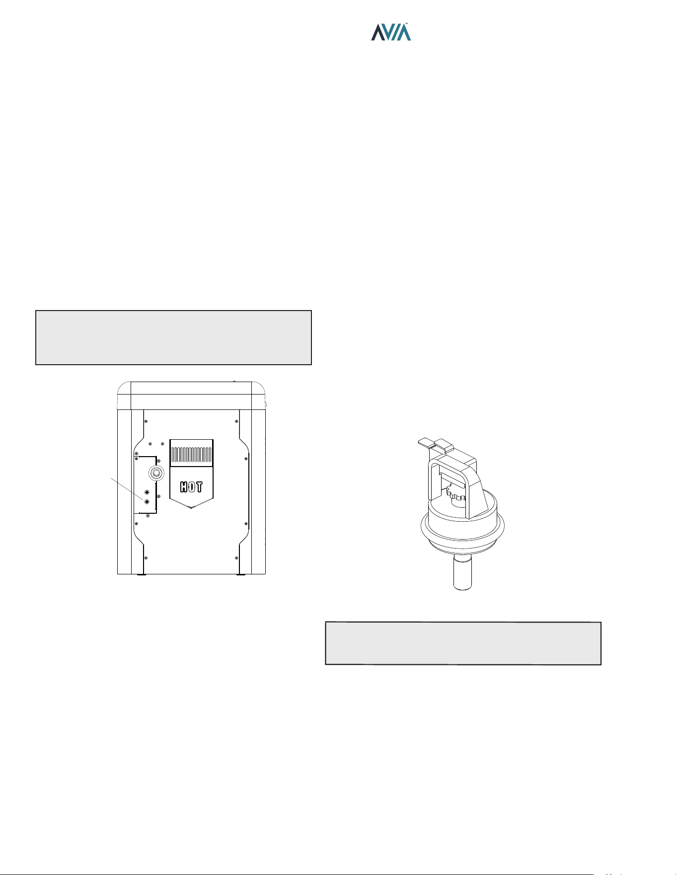
38
INSTALLATION & OPERATION MANUAL
Time Clock/Fireman’s Switch
To operate the heater with a time clock, connect the timer
to the clock/reman’s switch connection in the heater’s
wiring.
The time clock should be of the dual-switch type and set
to "shuto the call-for-heat" to the pool heater 15 to 20
minutes prior to shutting down the pool pump.
The reman’s switch connection is located at the power
junction box. Splice into the Purple wire jumper tagged
[“Where necessary add “Fireman’s switch circuit here”] to
connect the time clock. See Figure 58.
The reman’s switch connection must be a dry contact
and must not supply power to the heater. Powering the
reman’s switch connection externally may damage
the heater, and is not covered by warranty.
Do not exceed 50' (15 m) of total wiring using 18 AWG
stranded copper wire rated for 221°F (105°C) minimum.
NOTE: When using a time clock, the heater will display
“Clock/Fireman Sw” when the reman’s switch is open,
indicating that the time clock has shuto the call-for-
heat.
CLOCK/
FIREMAN
SWITCH
WIRE
JUMPER
F10829-1
Figure 58. Clock/Fireman Switch Wire Location
Water Pressure Switch
The water pressure switch ensures that the heater operates
only when the lter pump is in operation. It is located on the
In/Out header. It is factory-set at 1.75 PSI for deck level
installation.
Water Pressure Switch Adjustment
When the heater is located below the level of the spa or
pool, it may be necessary to adjust the pressure switch to
compensate for the no-ow static head. If it is necessary
to adjust the water pressure switch, do the following:
1. Make sure the pool filter is clean before adjusting
the switch.
2. Set the heater control to the OFF mode.
3. Turn the filter pump ON and confirm that the pressure
switch is closed (use a multimeter to check). If the
pressure switch fails to close, either the switch
setting is too high or not enough pressure is being
supplied by the filter pump.
4. Turn the heater ON.
5. Manually turn the pressure adjustment knob
clockwise until the heater shuts off. (A flat screwdriver
may be necessary if knob is too tight.)
6. Slowly turn the adjustment knob counter-clockwise
until the heater calls-for-heat again.
7. Turn an additional 1/2 turn counter-clockwise.
8. While the heater is running, check the adjustment
by turning the pump off and on several times. The
burners should shut off immediately when the pump
is turned off. If it does not, repeat the above steps
until proper operation is observed.
F10671
Figure 59. Water Pressure Switch Assembly
NOTE:
The sheet metal access panels should be in
place at all times to protect the water pressure switch
from rain and other environmental factors.
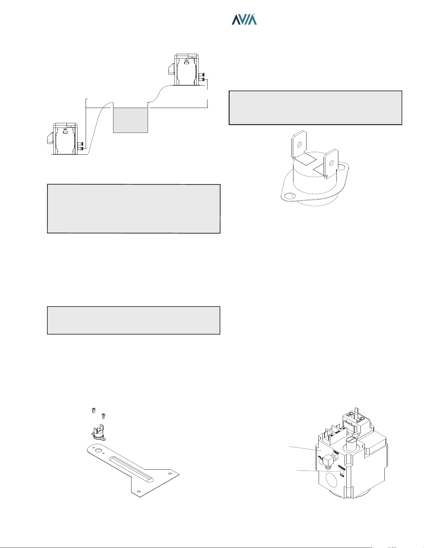
39
INSTALLATION & OPERATION MANUAL
5 ft. (1.52 m) MAX
POOL OR SPA
5 ft. (1.52 m)
MAX
MAY REQUIRE ADJUSTMENT
FOR HIGHER PRESSURE
MAY REQUIRE ADJUSTMENT
FOR LOWER PRESSURE
Figure 60. Pressure Switch Adjustment Requirements
NOTE:
If heater is installed outside of the limits shown,
a higher-pressure rated (11 psi / 76 kPa) switch may be
used. A ow switch, mounted and wired adjacent to the
heater, may be used in place of the factory-mounted
pressure switch. See "Illustrated Parts List" on page
84 for 11 psi / 76 kPa water pressure switch.
Two-Speed and Variable Speed Pumps
In some cases, the ow on the low-speed is insucient
to operate the heater. This is apparent when the water
pressure switch cannot be further adjusted or if the heater
makes banging noises or shuts o on high limit. In these
cases, the pump must be run at high speed when heating
the water.
A
CAUTION: Do not operate the heater without the
function of a properly-adjusted water pressure switch or
ow switch.
Cabinet Limit Switch
Heaters are equipped with a cabinet limit switch to prevent
the overheating of the components inside the cabinet in
case of any ue gas leakage from combustion chamber. It
is a "manual-reset" type switch that must be reset by the
service technician after making sure any leaks or damage
to the unit has been xed.
Figure 61. Cabinet Limit Switch – Manual-Reset
High Limits
The heater is equipped with two high limits, both are
automatic and are located in the inlet/outlet header.
Although both limits are preset to auto-reset, the control
board will request the operator to press "MODE" key if
either limit is tripped while the heater is running.
NOTE: An erratic high limit is often characteristic of an
internal heat exchanger problem, e.g. scale build-up, or
defective bypass. Refer to "Troubleshooting" on page
48.
AUTO-RESET
F10848
Figure 62. High Limit Switch
High Limit Removal
1. Shut off main electrical power switch to heater.
2. Remove inlet/outlet sheet metal access panel.
3. Remove defective high limit and replace with the
correct, new high limit.
4. Replace access panel.
Adjusting Valve Manifold Pressure
1. Remove the cap to gain access to the adjustment
screw.
2. Turn the adjustment screw clockwise to increase
pressure. (For example, at -0.6" WC turning
clockwise will increase the pressure to -0.5" WC,
-0.4" WC, etc.)
3. The manifold pressure should be negative -0.30
"WC (+/- 0.20 "WC) while running. If a combustion
analyzer is available, the O2 reading should be
between 4.5 - 5.5% O2 while running.
4. Install the cap before reading the manifold pressure.
GAS VALVE
MANIFOLD
PRESSURE TAP
Figure 63. Manifold Pressure Adjustment
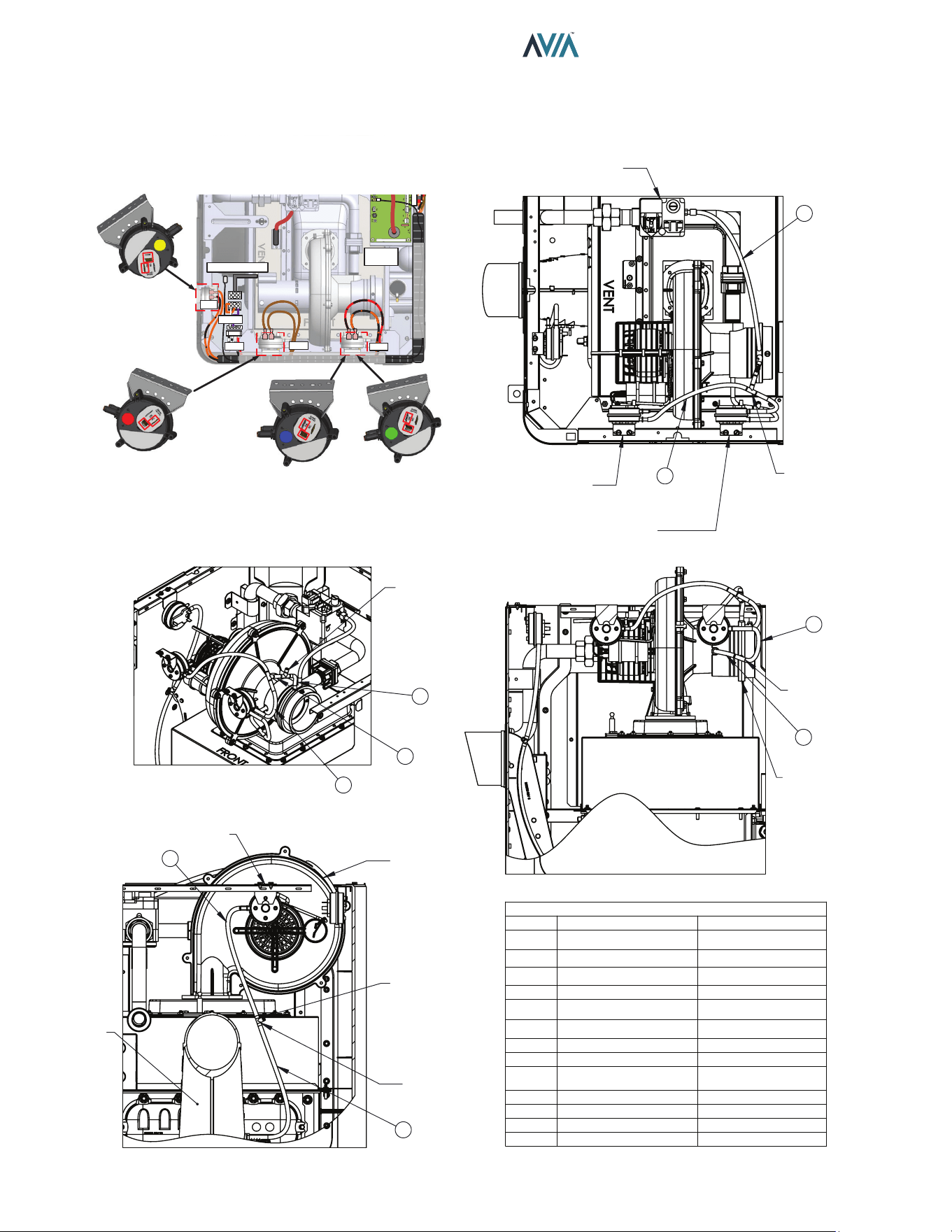
40
INSTALLATION & OPERATION MANUAL
Air Pressure Switches and Hoses
Use next illustration as reference to check correct connection of air pressure switches and hoses.
HOSE #
TO
FROM
1
GAS VALVE (VENT)
VENTURI (SUCTION #1)
2
TEE #1
VENTURI (SUCTION #2)
TEE #1
HOSE #3 &4
HOSE #2
3
DPS (+SIDE)
TEE #1
4
TEE #2 TEE #1
TEE #2
HOSE #5 & CAP
HOSE #4
5
APS (-SIDE)
TEE #2
6
TEE #3
BLOWER
TEE #3
HOSE #7 & CAP
HOSE #6
7
DPS (-SIDE)
TEE #3
8
VENT SWITCH (+SIDE)
TEE #4
9
TEE #4
EXHAUST
TEE #4
HOSE #9 & CAP
HOSE #8
APS
DPS
SPARK
IGNITER
FLUE SENSOR
VNT
240V
FAN
+
-
NC - COM
NC - COM
VENT PRESSURE
SWITCH
AIR PRESSURE
SWITCH
DIFFERENTIAL
PRESSURE
SWITCH-404
DIFFERENTIAL
PRESSURE
SWITCH-264
+
-
+
-
+
-
NO - COM
1
5
-
+ +
-
SWITCH-PRESSURE
DIFFERENTIAL NO
SWITCH-PRESSURE
AIR NC
TEE #2
GAS VALVE
6
7
VENTURI
TEE #3
TEE #1
2
3
4
8
9
EXHAUST
BLOWER
+
SWITCH-PRESSURE VENT NC
TEE #4
CAP
1/4 HOSE ROUTING
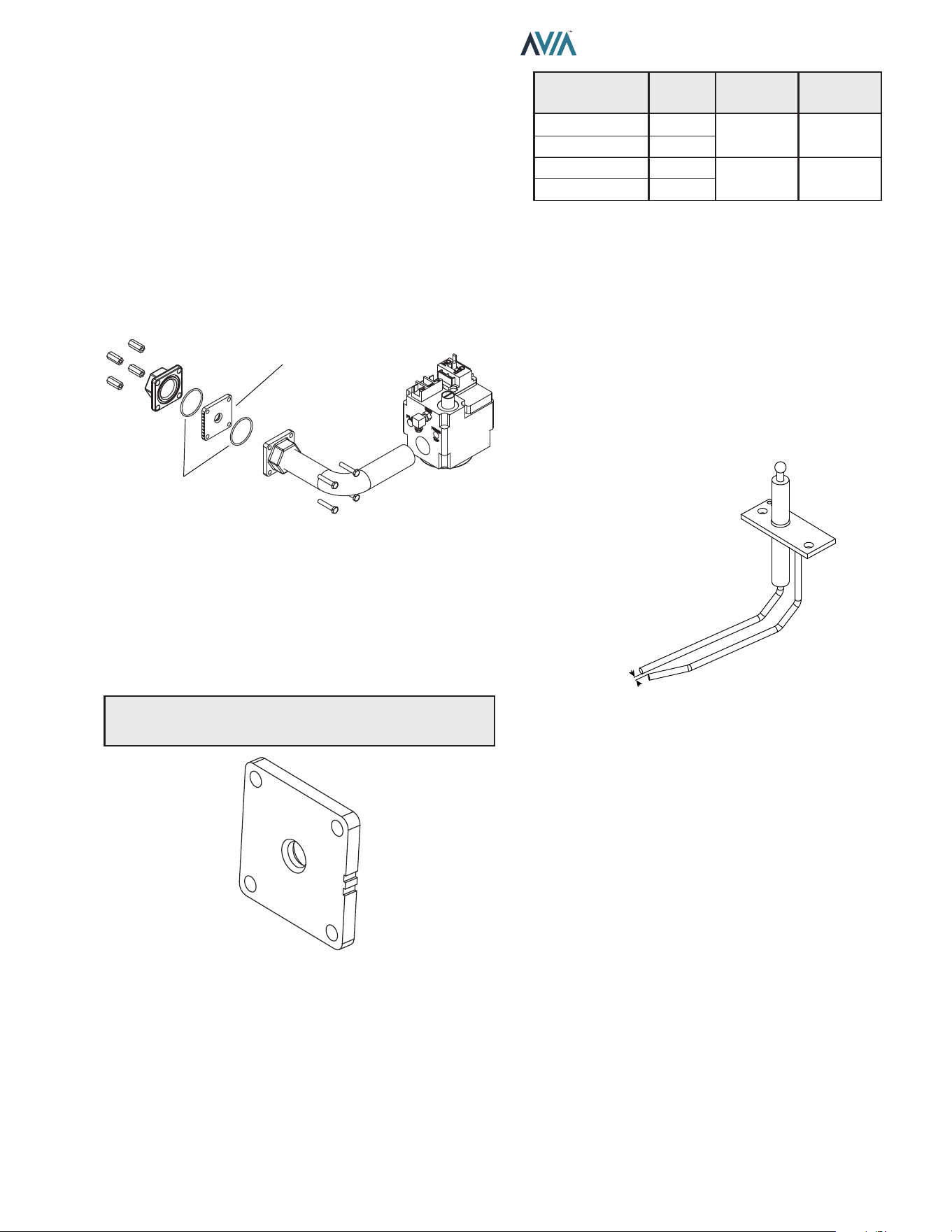
41
INSTALLATION & OPERATION MANUAL
Orice Removal
1. Locate and close the external manual shutoff valve.
2. Loosen the external gas union.
3. Locate and remove jacket top.
4. Locate and remove the four (4) bolts & nuts holding
the gas orifice in place. See Figure 64.
5. Carefully remove the gas orifice and do not misplace
the O-rings attached to the flanges.
6. Inspect and/or replace the orifice with the correct
size.
GAS ORIFICE
BRACKET
O-RING
Figure 64. Orice Location
Gas Orice Selection
Use Table R for the right gas orice selection. Propane
orices can be identied by the black paint on the edges.
The notches should face up for easy identication.
The gas orice is located on the gas train, between the gas
valve and the combustion blower.
NOTE: Gas orices for propane gas have a black oxide
nish.
Figure 65. Gas Orice
Pockets /
Notches
Model Gas Type Finish
1 264
Natural None
2 404
1 264
Propane Black
2 404
Table R. Gas Orice Selection
Igniter Removal.
1. Remove top cover.
2. Disconnect spark cable from igniter.
3. Use M10 socket, remove the two nuts holding the
igniter.
4. Carefully remove igniter and gasket.
5. When replacing igniter, be sure to add a new gasket
when installing igniter.
.15 +/- .01
Figure 66. Igniter
Burner Removal
1. See “Combustion Blower Removal” steps below.
Must remove blower to reach the burner.
2. Once the blower is removed. Use an M10 socket to
remove the sixteen (16) nuts holding down the burner.
3. Be sure to install a new gasket before installing the
burner.
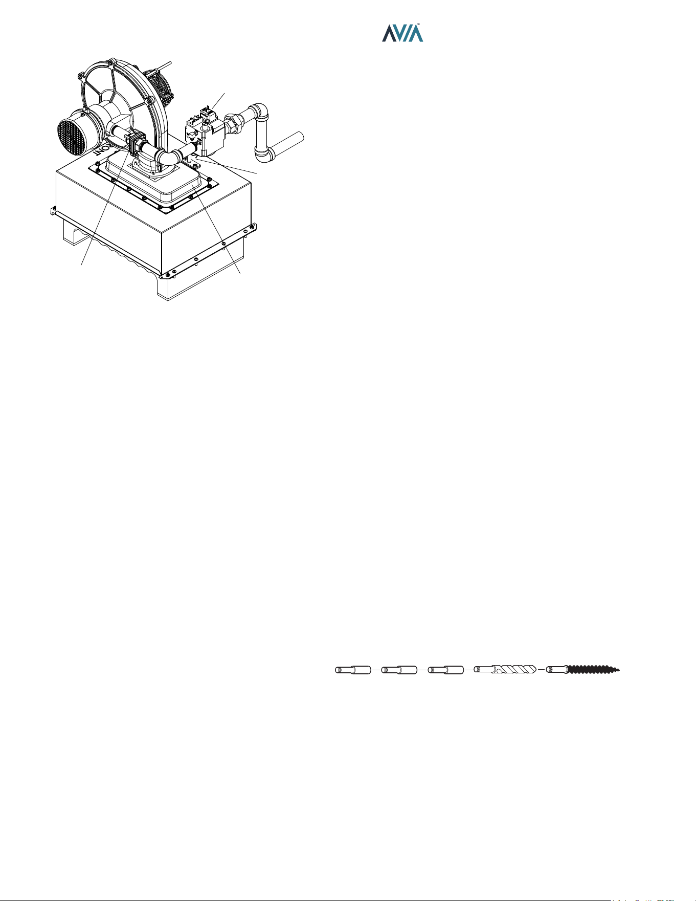
42
INSTALLATION & OPERATION MANUAL
GAS ORIFICE
BURNER
IGNITER
GAS VALVE
Figure 67. Burner/Gas Train
Combustion Blower Removal
1. Shut off main electrical power switch to heater.
2. Shut off gas upstream of heater.
3. Remove top cover.
4. Disconnect gas line from gas valve by unscrewing
union fitting along the gas train.
5. Disconnect the supply power connector from the
blower.
6. Disconnect 24V power leads from gas valve.
7. Remove suction hoses from the venturi and blower.
8. Use M10 socket to remove (4) nuts from base of the
blower. Then lift and remove blower.
Gas Valve Removal
1. Shut off gas supply to heater.
2. Remove top cover.
3. Unscrew the union fitting on gas train.
4. Remove the 24V power leads from the gas valve.
5. Remove tracking hose from the gas valve to the
venturi.
6. Use a pipe wrench to hold the other end of the gas
train (pipe connected to blower), while using another
pipe wrench to torque the gas valve counterclockwise
and remove from assembly. Alternatively, you can
remove the gas orifice flange to access the valve gas
train.
Heat Exchanger Removal
1. Shut off water, gas, and power to unit. Release
any pressure in water lines. Then remove water
connections to heater.
2. Remove top cover. Disconnect power leads from
rocker switch along with the cable attached to the
user interface. Then set cover aside. (*It will be easier
to work on heater with the cover totally removed but
might not be necessary*).
3. Perform the steps in “Combustion Blower Removal”.
4. Use Philips head screwdriver to remove screws from
all jacket panels.
5. Use a Philips head screwdriver to remove (8)
machine screws along the side of the combustion
chamber (there are 4 on each side), and the two (2)
sheet metal pieces that hold the combustion box to
the side panels.
6. Carefully lift top combustion chamber from the base
and remove it from the heater.
7. Use ½” socket to remove (8) nuts from the side
brackets that hold the heat exchanger onto the base
(there are 2 nuts per bracket).
8. Use a crescent wrench to remove the (2) water
temperature sensors on the side of the main header.
9. Remove the (4) wire leads connected to the high limit
switches.
10. Lift the heat exchanger and remove from unit.
Tube Cleaning Procedure
Establish a regular inspection schedule, the frequency
depending on the local water conditions and the severity
of service. Do not let the tubes clog up solidly. Clean out
deposits over 1/16" (1.6 mm) in thickness.
The heater may be cleaned from the return header
side, without breaking pipe connections. It is preferable,
however, to remove both headers for better visibility
through the tubes and to be sure the ground-up lime dust
does not get into the system.
After reaming, mount the wire brush in place of the auger
and clean out debris remaining in the tubes.
Another method is to remove the heat exchanger, ream
tubes and immerse heat exchanger in non-inhibited
de-scale solvent for severe scale build-up.
Extension
Pieces (2)
Auger
with Carbide Tip
Wire Brush
Figure 68. De-Liming Cleaning Kit (#052871F)
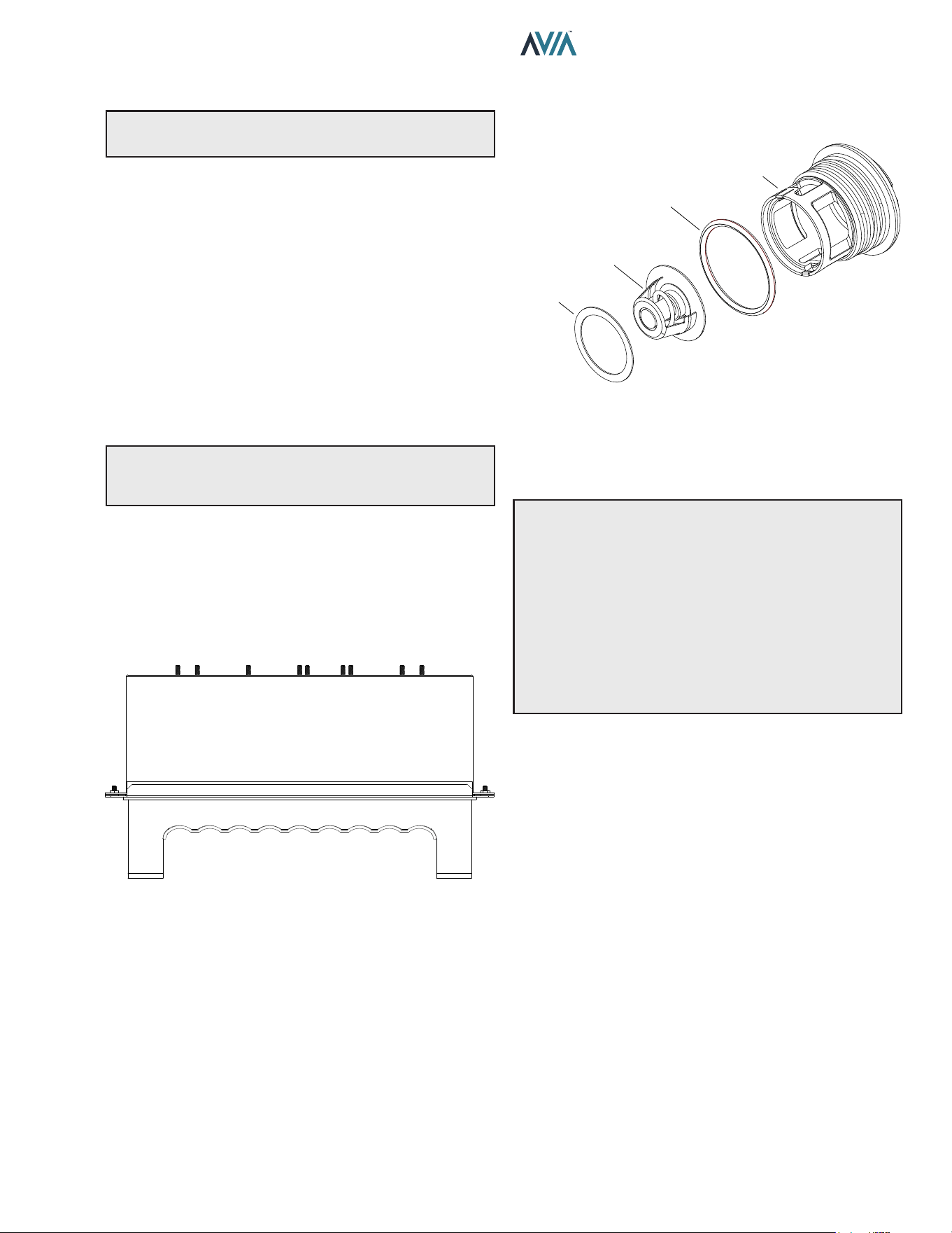
43
INSTALLATION & OPERATION MANUAL
Desooting Procedure
A
WARNING: Soot Is Combustible. Exercise Extreme
Care.
Soot will clog areas between ns and cause eventual
tube failure. Any sign of soot at the base of the burners or
around the outer jacket indicates a need for cleaning.
1. Follow the heat exchanger removal process as
shown in "Heat Exchanger Removal" section.
2. The heat exchanger has a baffle on the sides, or the
bottom, depending on the model size, which has to
be removed.
3. Remove the heat exchanger from the unit and wash
with a garden hose, making sure soot is removed
from the spaces between the fins.
4. Reverse the heat exchanger removal procedure to
reinstall.
NOTE: In extreme cases it may be necessary to do
steam cleaning at the local car wash. DO NOT WIRE
BRUSH.
Heat Exchanger Reinstall
It is highly recommended to replace the top combustion
chamber with the refractory during the heat exchanger
reinstallation process. Failing to do so can result in
damage to the heater and potential dangerous operating
conditions. See Figure 69.
Figure 69. Top Combustion Chamber
Unitherm Governor (U.G.) Replacement
1. Shut off water, gas and electricity, close valves and
relieve pressure.
2. Drain heat exchanger.
3. Remove retainer plug located next to the outlet pipe
connection.
4. Unsnap old U.G. to remove from retainer plug. Snap
in new U.G.
A
WARNING: When removing the burners or heat
exchangers, take precautions to avoid creating airborne
dust and avoid inhaling airborne bers. When cleaning
spills, use wet sweeping or High Eciency Particulate
Air (HEPA) ltered vacuum to minimize airborne dust.
Use feasible engineering controls such as local exhaust
ventilation or dust collecting systems to minimize
airborne dust. Wear appropriate personal protective
equipment including gloves, safety glasses with side
shields, and appropriate NIOSH-certied respiratory
protection, to avoid inhalation of airborne dust and
airborne ber particles.
UG PLUG
UNITHERM
GOVERNOR
GASKET
UG PLUG O-RING
Figure 70. Unitherm Governor
To test the operation of the Unitherm Governor, place in
hot water over 120°F (49°C), and watch for movement
against spring. If there is no movement, replace the UG.
5. Reinstall retainer plug, taking care to lubricate
gasket with a non-petroleum based grease such as
AquaLube.
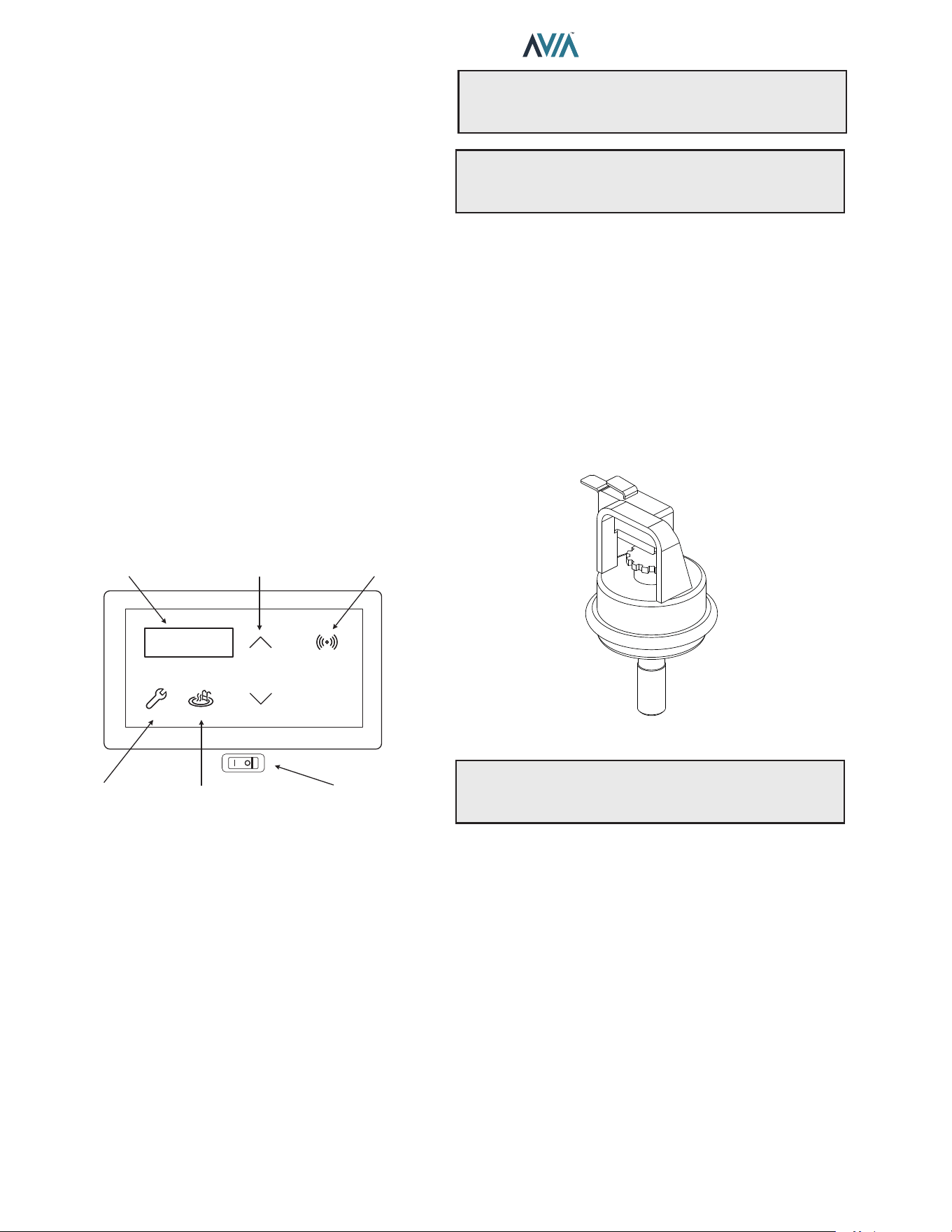
44
INSTALLATION & OPERATION MANUAL
8. OPERATING
INSTRUCTIONS
Before Start-Up
Burners
Keep heater area clear and free from combustibles,
ammable liquids and chemicals. Do not obstruct the ow
of combustion and ventilation air.
Water
Water must be owing through the heater during operation.
Ensure that the system is lled with water and that the
pump is operating. The heater should always have a
minimum of 40 GPM (151 lpm) water owing through it.
Start-Up Procedures
Your pool and spa heater has been designed for years of
safe and reliable pool/spa water heating. It is available with
electronic ignition only. This manual provides installation,
operation, maintenance, and service information for these
heaters.
MODESERVICE
DOWN
UP
CONNECT
LCD DISPLAY TEMP ADJUST CONNECT MENU
SERVICE MENU MODE KEY
ON / OFF
SWITCH
Figure 71. Heater Control Toggle Switch
If your heater has been installed correctly, operating the
heater is an easy task. The upper front panel of the heater
contains the control center that allows you to turn the
heater On or O and adjust the temperature settings for
the pool or spa. The temperature range is factory-set from
65°F (18°C) to 104°F (40°C). See Figure 71 for location of
toggle switch to turn the heater On and O.
See "Controls" section on page 27 for additional details
about the use of the controls in the Control Adjustments
subsection.
After Start-Up
Feel the inlet and outlet pipes. Outlet pipe should be only
slightly warmer than the inlet. It should not be hot.
A
WARNING: Should overheating occur or the gas
supply fail to shut o, turn o the manual gas control to
the appliance.
A
AVERTISSEMENT: En cas de surchaue ou
si l’alimentation en gaz ne s’arrete pas, fermez
manueiiement ie robinet d’arret de l’admission de gaz.
Water Pressure Switch
A water pressure switch is provided in the heater to shut o
the burners in the event that water supply is interrupted. It
is very important to verify that the switch electrically opens
and shuts o the gas valve when water ow to the heater is
interrupted. Otherwise, rapid and severe damage will likely
occur to the heater.
The water pressure switch should be checked and adjusted
for proper operation by a qualied service person at the
time of installation and periodically checked thereafter.
Refer to "Water Pressure Switch Adjustment" on page
38.
F10671
Figure 72. Water Pressure Switch
A
WARNING: Operation of the heater without water
circulation will cause rapid and severe damage to the
heater, which will not be covered under warranty.
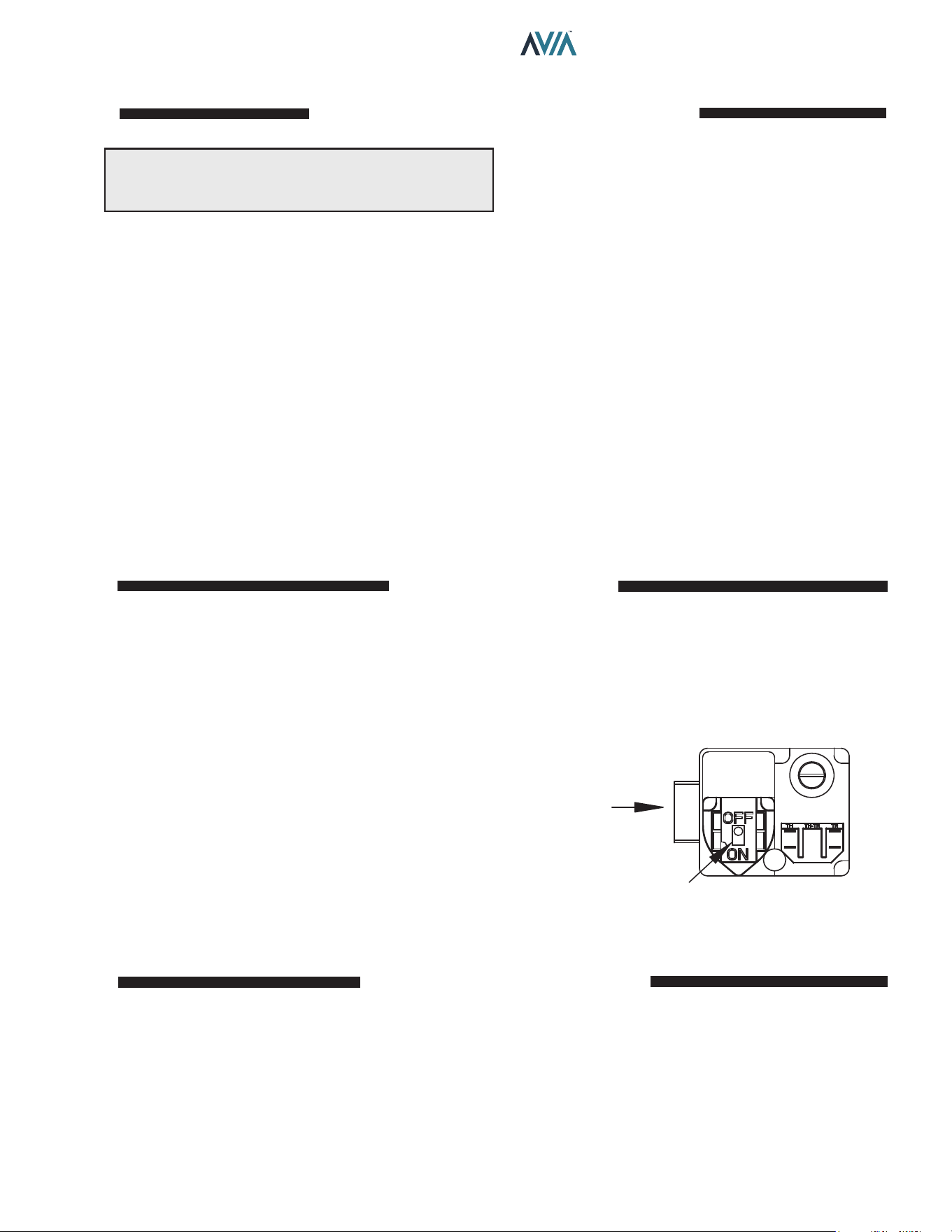
45
INSTALLATION & OPERATION MANUAL
OPERATING INSTRUCTIONS AND SHUTOFF PROCEDURES - DIRECT IGNITION SYSTEMS
1. STOP! Read the safety information above on this
label.
2. Set the thermostat to the lowest settings.
3. Turn off all electric power to the appliance.
4. This appliance does not have a pilot. It is equipped
with an ignition device which automatically lights the
burner. Do not try to light the burner by hand.
5. Remove the heater's top panel.
6. Pull toggle style switch away from you to turn gas
“OFF”.
7. Wait five (5) minutes to clear out any gas. Then smell
for gas, including near the floor. If you smell gas
STOP! Follow “B” in the safety information above on
this label. If you don’t smell gas, go to the next step.
8. Push the toggle switch towards you to turn the gas
“ON”.
LIGHTING INSTRUCTIONS
1. Set the thermostat at the lowest setting.
2. Turn o all the electrical power to the appliance if
service is to be performed.
3. Remove the heater's top panel.
TO TURN OFF GAS TO APPLIANCE
4. Pull toggle style switch away from you to turn gas
“OFF”.
5. Replace heater door panel.
9. Replace heater door panel.
10. Turn on all electric power to the appliance.
11. Set thermostat to desired setting.
12. If the appliance will not operate, follow the instructions
“To Turn Off Gas To Appliance” and call your service
technician or gas supplier.
Gas
Inlet
Gas Control
Knob Show In “OFF”
Position
FOR YOUR SAFETY READ BEFORE LIGHTING
A. This appliance does not have a pilot. It is equipped
with an ignition controller which automatically
lights the burner. DO NOT try to light the burner
by hand.
B. BEFORE OPERATING smell all around the
appliance area for gas. Be sure to smell next to
the floor because some gas is heavier than air and
will settle on the floor.\
WHAT TO DO IF YOU SMELL GAS:
• Do not try to light any appliance.
• Do not touch any electric switch; do not use any
phone in your building.
• Immediately call your gas supplier from a neighbor’s
phone. Follow the gas supplier’s instructions.
• If you cannot reach your gas supplier, call the re
department.
C. Use only your hand to turn the gas control ON or OFF.
Never use tools. If you cannot change the ON/OFF
setting by hand, do not try to repair it, call a qualified
service technician. Force or attempted repair may
result in a fire or explosion.
D. Do not use this appliance if any part has been under
water. Immediately call a qualified service technician
to inspect the appliance and to replace any part of the
control system and any gas control which has been
under water.
A
WARNING: If you do not follow these instructions
exactly, a re or explosion may result causing property
damage, personal injury or loss of life.
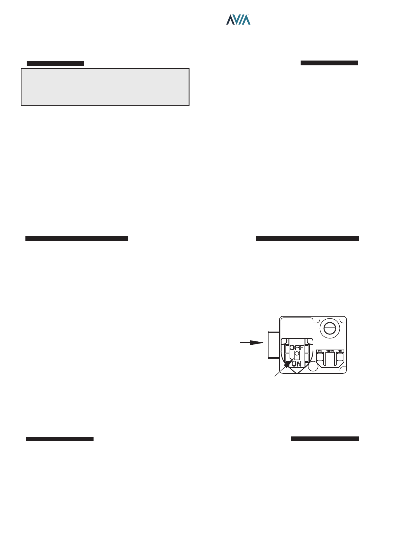
46
INSTALLATION & OPERATION MANUAL
INSTRUCTIONS D'UTILISATION ET PROCÉDURES D'ARRÊT
MODÈLES NUMÉRIQUES À ALLUMAGE ÉLECTRONIQUE
SYSTÈME D'ALLUMAGE DIRECT
1. ARRETEZ! Lisez les instructions de sécurité sur la
portion supérieure (a gauche) de cette étiqutte.
2. Réglez le thermostat a la température la plus basse.
3. Coupez l'alimentation électrique de l'appareil.
4. Cet appareil ne comporte pas de veilleuse, Il
est muni d'un dispositif d'allumage qui allume
automatiquement le bruleur. Ne tentez pas d'allumer
le bruleur manuellement.
5. Retirez le panneau de porte du radiateur.
6. Tirez l'interrupteur a bascule loin de vous pour
allumer le gaz "OFF".
7. Attendre cinq (5) minutes pour laisser echapper tout
le gaz. Reniflez tout autour de l'appareil, y compris
pres du plancher, pour deceler une odeur de gaz. Si
vous sentez une odeur de gaz, ARRETEZ! Passez a
l'etape B des instructions de sercurite sur la portion
supérieure (a gauche) de cette étiqutte. S'il n'y a pas
d'odeur de gaz, passez a l'etape suivante.
8. Poussez l'interrupteura a bascule vers vous pour
tourner le gaz "ON".
INSTRUCTIONS DE MISE EN MARCHE
1. Réglez le thermostat au réglage le plus bas.
2. Coupez toute l'alimentation électrique de l'appareil si
le service doit être eectué.
3. Retirez le panneau de porte du radiateur.
COMMENT COUPER L'ADMISSION DE GAZ DE L'APPAREIL
4. Tirez l'interrupteur à bascule loin de votre pour
tourner le gaz "DÉSACTIVÉ".
5. Replacez le panneau de porte du radiateur.
9. Remplacez panneau dle e porte du radiateur.
10. Mettez l'appareil sous tension.
11. Reglez le thermostat à la température.
12. Si appareil ne se met pas en marche, suivez les
instructions intitulees. Comment couper l'admission
de gaz de l'appareilet appelez un technicien qualifie
ou le fournisseur de gaz.
Entrée
de gaz
Le bouton de contrôle du
gaz montre en position
"OFF"
POUR VOTRE SÉCURITÉ LISEZ AVANT DE METTRE EN MARCHE
A. Cet appareil ne comporte pas de veilleuse. Il
est muni d'un dispositif d'allumage qui allume
automatiquementle brileur. Ne tentez pas
d' allumerle bruleur manuellement.
B. AVANT DE FAIRE FONCTIONNER, reniflez tout
autour de l'appareil pour déceler une odeur de
gaz. Reniflez pres du plancher, car certains gaz
sont plus lourds que l'air et peuvent accumuler au
niveau du sol.
QUE FAIRE Sl VOUS SENTEZ UNE ODEUR DE
GAZ:
• Ne pas tenter d'allumer d' appareil. Ne touchez
å aucun interrupteur; ne pas vous servir des
telephones se trouvant dans le batiment.
• Appelez immédiatement votre fournisseur de
gaz depuis un voisin. Suivez les instructions du
fournisseur.
• Si vous ne pouvez rejoindre le fournisseur, appelez le
service des incendies.
C. Ne poussez ou tournez la manette d'admission du gaz
qu'å la main; ne jamais utiliser d'outil. Si la manette
reste coincée, ne pas tenter de la réparer; appelez
un technicien qualifié. Le fait de forcer la manette ou
de la réparer peut déclencher une explosion ou un
incendie.
D. N'utilisez pas cet appareil s'il a été plongé dans l'eau,
méme partiellement. Faites inspecter l'appareil par
un technicien qualifié et remplacez toute partie du
systeme de contröle et toute commande qui ont été
plongés dans l'eau.
AVERTISSEMENT: Quiconque ne respecte pas à la
lettre les instructions dans la prèsente notice risque de
dèclencher un incendie ou une explosion entrainant des
dommages, des blessures ou la mort.
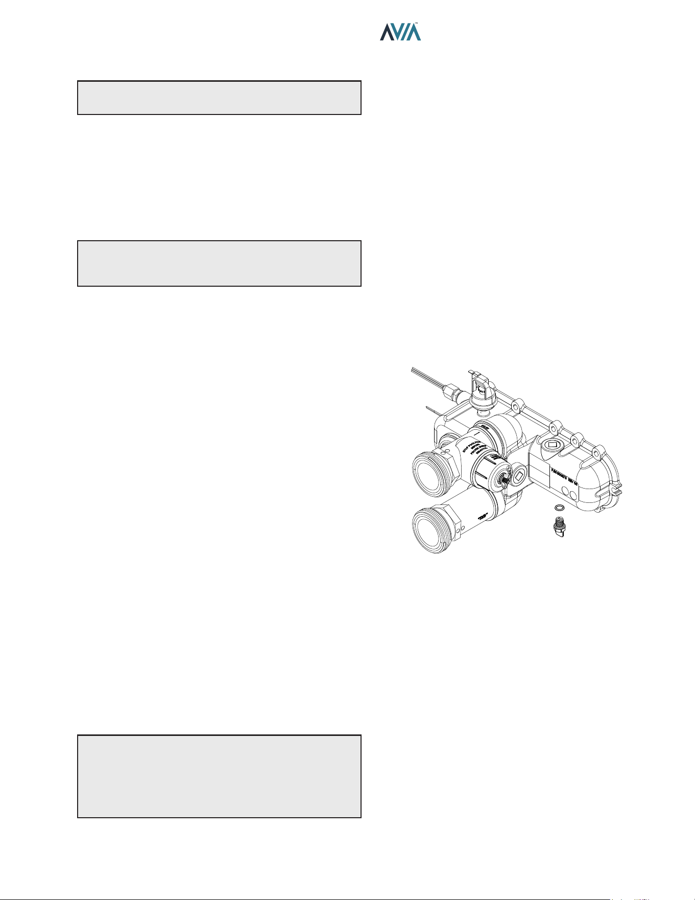
47
INSTALLATION & OPERATION MANUAL
9. MAINTENANCE AND CARE
A
WARNING: Check the heater for possible rodent
nests after long periods of non-use.
Perform the following maintenance operations one
year after initial start-up and then semi-annually.
1. Inspect and operate all controls, gas valve and
pressure relief valve (if equipped).
2. On indoor heaters, clean room intake openings to
ensure adequate flow of combustion and ventilation
air.
A
CAUTION: Combustion air must not be contaminated
by corrosive chemical fumes which can damage the
heater. Such damage will not be covered under warranty.
3. Keep area around heater clear and free from
combustible materials, gasoline and other flammable
and corrosive vapors and liquids.
If Heater Will Not Fire:
If you have no electrical power, it may be that your “circuit
breaker” has tripped. Try re-setting it.
If you have electrical power but the heater will not re
check the following or see "Troubleshooting" on page
48:
1. The time clock must be in the ON position.
2. Your pump strainer basket may be full. If so, remove
debris.
3. Your filter may be dirty. If so, backwash or clean
filter. (To tell if your filter is dirty, look to see if the filter
pressure reading is higher than usual).
4. The pump may have lost its prime and be running
dry. Check the pressure on the filter. If there is no
pressure; then you are not moving water (or your
gauge is broken). Try to get the pump to run at its
normal flow rate.
Cold Weather Operation
Important Freeze Information
MODERATE CLIMATE: Heater operation can continue
during short-term cold spells. When temperatures are
between 0°F (-18°C) and 32°F (0°C), ow (continuous
pump operation) must be maintained.
A
CAUTION: Do not use the heater to maintain
water temperatures just above freezing or for freeze
protection. When heater is used during freezing weather,
care must be taken to avoid freeze-ups. Continuous
pump operation is a must. Additional protection may be
required. The heater is not warranted against freeze-ups.
COLD CLIMATE: Prolonged operation with water
temperatures below 50°F (10°C) is not recommended.
When starting the heater with water temperatures below
50°F (10°C), operate the heater continuously until higher
temperatures are reached. Operating the heater for
prolonged periods with pool water below 50°F (10°C)
can seriously damage the heater, and is not covered by
the warranty. For cold climate areas, please follow the
winterizing procedures listed below.
Winterizing the Pool and Spa Heater
Heaters installed outdoors in freezing climate areas may be
shut down for the winter. Observe the following procedure
for winterizing the heater:
1. Turn off gas valve, manual gas valve, and electrical
supply to the heater.
2. On the water connection, close any isolation valve
to isolate the heater. Remove the lower right access
panel to reveal the right side of the Inlet/Outlet header.
The drain will be located underneath the header.
Loosen and remove the drain plug. See Figure 73.
DRAIN PLUG
O-RING
Figure 73. In/Out Header with Drain Plug
48
INSTALLATION & OPERATION MANUAL
10. TROUBLESHOOTING
Problem Possible Cause Corrective Action
LCD text ickering or no text Low or no voltage to control board .................. Check for 24VAC at control board P6.
Check transformer wiring to 240V or 120V.
Harmonics, or whining noise Unitherm governor inoperative ......................... Check movement by putting in hot water (above120°F [49°C] or
higher)
*Debris or restriction in system ........................ Locate the restriction and remove. Flush system and clean
*Debris in gas line............................................ Remove debris or blow out gas line
Low ow........................................................... Scale forming in heat exchanger - clean heat exchanger and check
pool pH and total alkalinity
Heater going on and o continuously Dirty lter ......................................................... Clean or replace lter
Low water level in pool .................................... Raise water level
External bypass setting out of adjustment ....... Adjust bypass
Pressure switch out of adjustment................... Adjust pressure switch
Liming or scale forming in
exchanger
Pool water........................................................ See Water Chemistry on page 5
Bypassing too much water .............................. Inspect bypass for movement, if no movement, replace
Unitherm governor not functioning .................. Replace if no movement when heated
Sooting High ow rates ................................................. Reduce by adding manual bypass valve
Adjust manual bypass valve until heater outlet water temp is between
105°F and 120°F (40°C and 49°C)
Unitherm governor inoperative ........................ Check movement by putting in hot water (above 120°F [49°C] or
higher). If no movement, replace
*Air starvation .................................................. Refer to installation instructions
*Improper venting ............................................ Follow recommended installation instructions
*Insects or debris clogging burner intake ports Clean burners
Flame outage or Flame strength
below 2 μA
Low gas pressure ............................................ Adjust gas pressure
Restricted/dirty igniter ...................................... Clean igniter and burners
Takes too long to heat pool or spa Under-sized heater .......................................... Calculate heating capacity of heater
Htr. output (BTUH)
Pool gallonage x 8.33
or refer to heater sizing chart
This does not take into account heat loss due to weather
Filter not running long enough ......................... Reset time clock
Dirty lter ......................................................... Clean lter
Gas line or meter undersized .......................... Refer to installation instructions. See page 18.
Leaking at heat exchanger Overacid .......................................................... Replace heat exchanger and maintain proper water chemistry
Gasket brittle and leaking -
(overheated)
Heater running after pump shuts o ................ See Pressure Switch Adjustment, See page 38.
Refractory damage .......................................... Replace refractory
Sooted heater .................................................. Determine cause of sooting and correct
Fan not running, "Di Sw Open" or
"Fan Lockout"
Incorrect blower jumper ................................... Check blower jumper matches 240V or 120V power supply.
Fan relay.......................................................... Check control board Fan relay terminals “Power” and “Blower”.
If relay is stuck open or close, replace control board.
Fan Connection ............................................... Loose connection or failed motor. Prolonged exposure to power with
the wrong blower jumper can damage the blower.
* Indicates symptom which usually occurs on initial start-up.
IMPORTANT NOTICE: These instructions are intended for the use of qualied personnel who are specically trained
and experienced in the installation of this type of heating equipment and related system components. Installation and
service personnel may be required by some states to be licensed. Persons not qualied shall not attempt to install this
equipment nor attempt repairs according to these instructions.
= approx. degF rise/hr
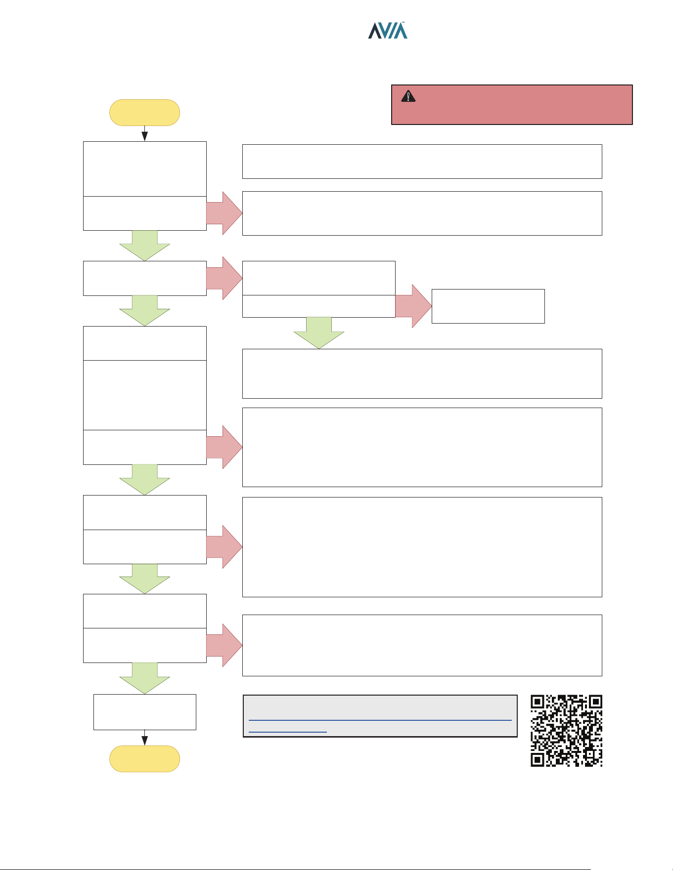
49
INSTALLATION & OPERATION MANUAL
Opera�on and Troubleshoo�ng – Flow Chart
Turn Gas Supply OFF.
Adjust Temperature
Setpoint to Call for Heat
Power to Control Board?
(24VAC Nominal)
YES
Troubleshooting
completed
END
START
NO
NOTE: Before troubleshooting, familiarize yourself with the start-up and
check-out procedure
Check line voltage power (120V or 240V), transformer voltage (24VAC), 5A
fuse, controller terminals and wiring. Make sure that line voltage is NOT
208VAC or below.
Spark across Igniter?
YES
WARNING: HIGH VOLTAGE
For qualified technicians ONLY
WARNING: HIGH VOLTAGE
For qualified technicians ONLY
NO
Pull ignition lead and check
spark at Control board.
Is spark OK? NO
YES
Replace Control Board
• Check ignition cable, ground wiring, ceramic insulator and gap, and correct.
• Check boot of the ignition cable for signs of melting or buckling. Take
protective action to shield cable and boot from excessive temperatures.
Turn Gas Supply ON
Wait for Heater to spark
again.
NOTE: If controller is
lockout, restart heater.
Burner Running?
YES
NO
• Check that all manual gas valves are open, supply tubing and pressures
are good, and burner orifice is not blocked.
• Check electrical connections between control board and gas valve.
• Check for 24 VAC across gas valve terminals on control board. If voltage is
okay, replace gas valve; if not, check main power or replace transformer.
Unit is Heating
Heater runs until call for
heat ends?
NO
• Check for Error Messages in the Display. See “Control Logic Flow”.
• Press SERVICE key to check that Flame strength is 5 μA or above.
• Check continuity of ignition cable and ground wire.
• If checks are okay, replace control board; If not, fix ground wiring, replace
high tension wire or igniter.
NOTE: If ground is poor or erratic, shutdowns may occur occasionally even
though operation is normal at the time of checkout.
YES
Call for Heat Ends
Unit Shuts off?
YES
NO
• Check Temperature setpoint, water temperature and proper keypad
operation.
• Remove gas valve lead at module; if valve closes, recheck temperature
controller and wiring; if not, replace gas valve.
NOTE: For more details please visit:
https://www.raypak.com/support/tech-corner/avia-
troubleshooting/
Operation and Troubleshooting - Flow Chart
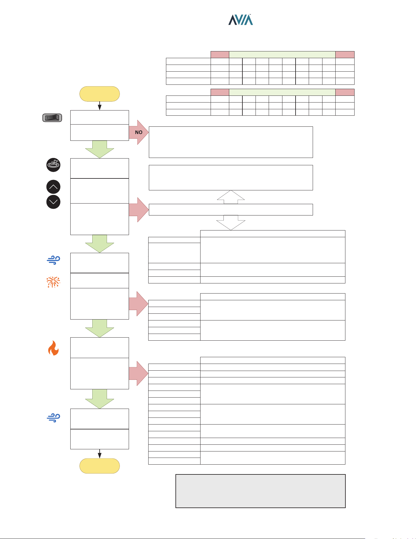
50
INSTALLATION & OPERATION MANUAL
Control Logic – Flow Chart
YES
YES
YES
YES
Blower “Post-Purge”
for 3 minutes
Wait for new Heat
demand
END
START
NO
NO
NO
• Check On/Off switch (under lid on control panel)
• Check for 240 or 120 volts to the transformer
(time clock, circuit breaker, wire connections)
• Check for 24 volts to Circuit Board (P6 connector)
Is a Fault Message displayed?
NO
“Remote” and Water Temperature displayed?
If Remote mode is set to control the heater,
Exit Remote control by pressing UP + DOWN.
YES
Inlet , Outlet or Vent
Temp [Open/Short]
Gas Valve
Flame w/o CFH
Low Voltage
Verify sensor per “Temperature-Resistance” table:
- Replace Sensor if readings are out of range.
- Replace Ignition board if sensor readings are right.
Check voltage at valve terminals. If terminals are
energized replace control boards, if not replace valve.
Check main voltage if voltage is below 23VAC.
Diff Sw Closed
Diff Sw Open
Fan Lockout
Ing Try Failure
Ign 60 min Delay
Ignition Lockout
Check for damaged or loose wires and terminals.
Check Gas valve, Gas supply and spark igniter:
- Check gas supply and valve operation.
- Check Igniter and wire. Replace if damaged.
Check Blower and Air Pressure switch:
- Replace Pressure switch if failing open or close.
- Replace Blower if operation is intermittent.
Clock/Fireman Sw
Water Sw Open
Vent Sw Open
Hi Limit 1 Fault
Hi Limit 2 Fault
Cabinet Temp Lm
Switch connected to safety loop is in OFF mode.
Air SW Open
Diff Sw Fault
Fan Lockout
Flame Lost
Flame Flickering
Flue Over Temp
Low Flow Fault
High Flow Fault
Verify water flow / pressure. Clean Filter/Strainer.
Vent switch open. Troubleshoot extractor if installed.
Temperature Limit switch open. Verify water flow.
Inspect internal thermostat (Unitherm Governor) and
bypass valve.
Air Pressure Switch failed in operation. Verify Blower
operation. Check for air inlet/outlet obstructions. Verify
air pressure.
Verify gas supply. Verify gas valve operation.
Cut power, verify and clean igniter rods.
Verify obstructions. Troubleshoot extractor if installed.
Verify water flow. Verify Pump operation. Adjust Flow as
necessary. Verify filter pressure and clean if needed.
Check for damaged or loose wires and terminals.
Outlet Over Temp
Verify water flow. Verify gas supply and combustion.
In Sensor Fault
Check for damaged or loose wires and terminals.
Inlet , Outlet or
Flue Sensor
[Open/Short]
Fahrenheit (°F)
Temperature-Resistance
Celsius (°C)
Inlet Sensor (kΩ)
Outlet Sensor (kΩ)
Flue Sensor (kΩ)
6.3
-14
open
short
40
4
261
26
1.03
50
10
199
20
1.09
60
15
153
15
1.14
70
21
119
12
1.19
80
27
93
9.3
1.25
90
32
73
7.3
1.35
100
38
58
5.8
1.57
110
43
46
4.6
1.77
187
86
short
short
open
Fahrenheit (°F)
Celsius (°C)
< 7.5
< -13
50
10
75
24
100
38
125
51
150
65
200
93
300
149
400
204
464
240
open
Below Above
Temperature-Resistance
Below Above
MODEMODE
UPUP
DOWNDOWN
Power On
Is the Display lit?
Push MODE
Select “Pool” or “Spa”
Push UP or DOWN
arrows to adjust
Temperature
Is Water Setpoint and
Water Temperature
displayed?
Blower “Pre-Purge”
for 45 sec
Spark
Is Water Setpoint,
Temperature and
“Heating” displayed?
Unit Heating until
demand is satisfied.
Was Water
Temperature
reached?
Control Logic - Flow Chart
NOTE: "Call Service" fault is auto-recovery after 60 min.
lockout. For control rmware 1.10 and 2.10: Press and
hold SERVICE key for 15-20 sec. Follow the instruction
in the LCD to clear "Call Service" fault.
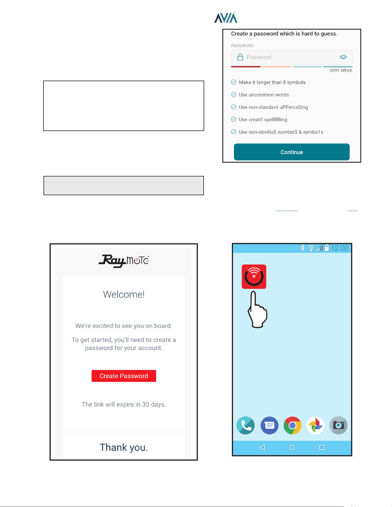
51
INSTALLATION & OPERATION MANUAL
11. CONNECT TO WI-FI WITH
RAYMOTE
Before initiating the provisioning process, make sure
a reliable Wi-Fi access point is located near the unit or
control room and a Wi-Fi network password is available.
Date: _______________________________________
Wi-Fi Network Name
(SSID): ______________________________________
Wi-Fi Password: _______________________________
Raymote User Registration
Sign up from your mobile device with the Raymote App.
Use your email to create a new account. You'll receive an
email conrmation. See Figure 74.
NOTE: Check your email spam if you do not receive an
email within 5-minutes in your inbox.
Use your email address as the Raymote user, then create
a secure password. See Figure 75.
Once the user registration is complete, you can begin
to add your AVIA heaters via the Raymote mobile app.
See Figure 80.
Figure 74. Welcome Raypak Dashboard
Figure 75. Create Password
Downloading the Raymote Mobile App
1. Download and install the Raymote mobile app from
the Google Play (Android): or App Store (iOS): on
your mobile device.
2. Find the Raymote mobile app icon on your device.
See Figure 76.
12:00
Figure 76. Find your Raymote Mobile App Icon
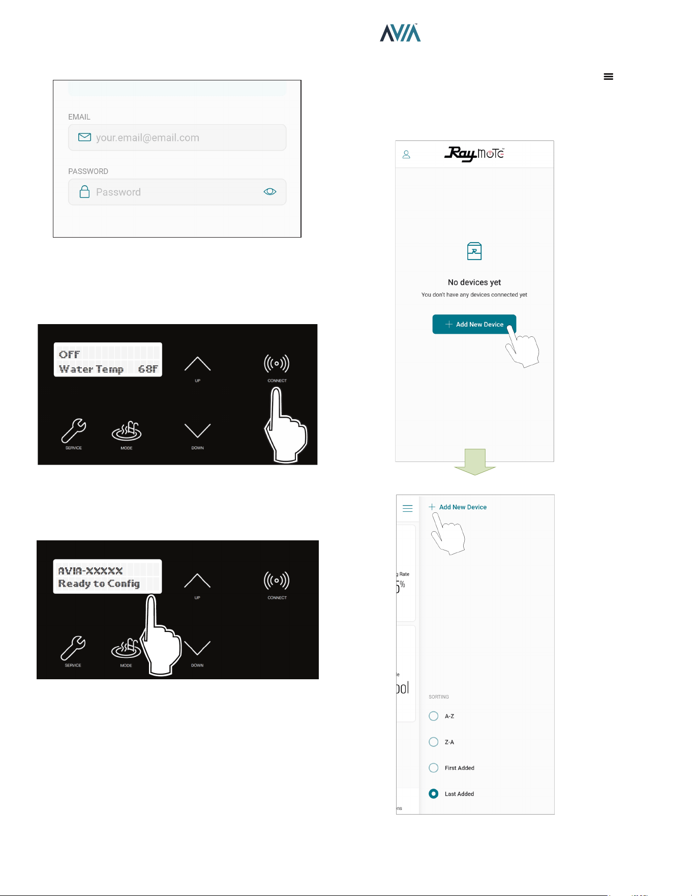
52
INSTALLATION & OPERATION MANUAL
3. Open the Raymote mobile app and log in with your
user name and password. See Figure 77.
Figure 77. Log in the Raymote Mobile App
Preparing the Unit for Connection
1. Stand near the display of the AVIA unit. Press the
CONNECT key. See Figure 78.
Figure 78. CONNECT Key
2. The CONNECT menu should display the Wi-Fi State,
indicating "Ready to Config" wireless connection,
and also the HOTSPOT identifier. See Figure 79.
Figure 79. Wi-Fi Ready to Congure and HOTSPOT
Identier
3. At this point your unit is ready for connection.
NOTE: The following sections provide the instructions for
Android and iPhone devices.
Add a New Heater to Raymote
1. In the Raymote app, press the menu button
located at the top left corner of the screen, then press
"+ Add new device". See Figure 80.
Figure 80. Add New Device
ADD THE FIRST UNIT
OR ADD MORE NEW UNITS
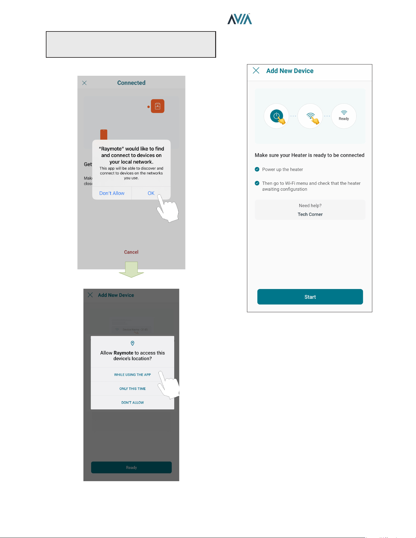
53
INSTALLATION & OPERATION MANUAL
NOTE: The rst time you use a new phone, the Raymote
mobile app may require you grant permission to access
data. See Figure 81.
iOS
OR ANDROID
Figure 81. Grant Permission
2. "Check your Device" screen will appear. Ensure to
have AVIA heater powered and Wi-Fi signal available
in the area, then press "Start" button. See Figure 82.
Figure 82. Check your Device
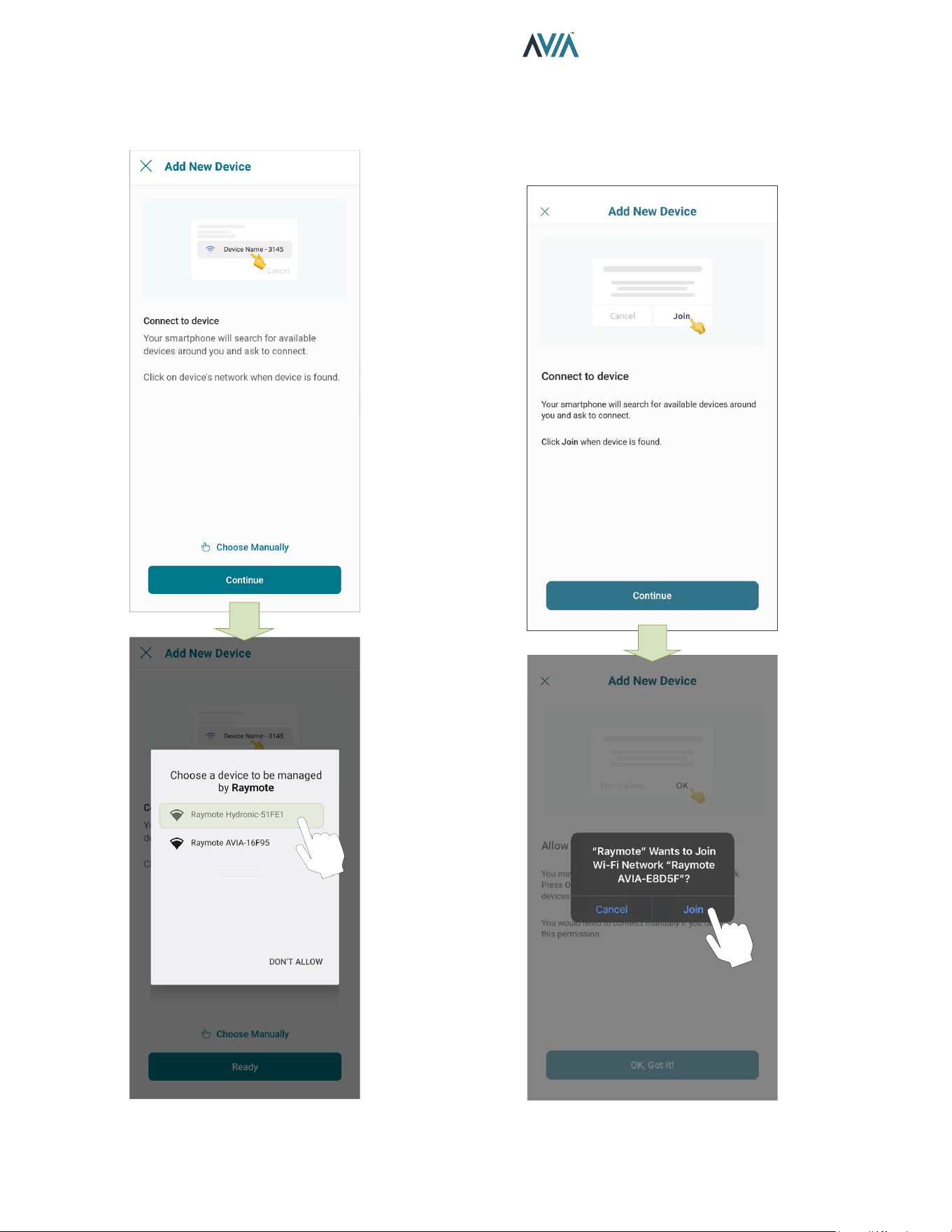
54
INSTALLATION & OPERATION MANUAL
3. In Android: Depending on your configuration, one
or more devices will appear on the app. Select the
HOTSPOT identifier that matches the unit's display
as shown in Figure 83.
Figure 83. Connect with Android Smart Phone
4. In iPhone: Raymote app will start to scan nearby
Heaters. If you have multiple units ready to connect,
stand closer to the unit you want to connect first.
Press "Join" to select the displayed heater that
matches the HOTSPOT identifier, or press "Cancel"
to start the process again. See Figure 84.
Figure 84. Connecting with iPhone
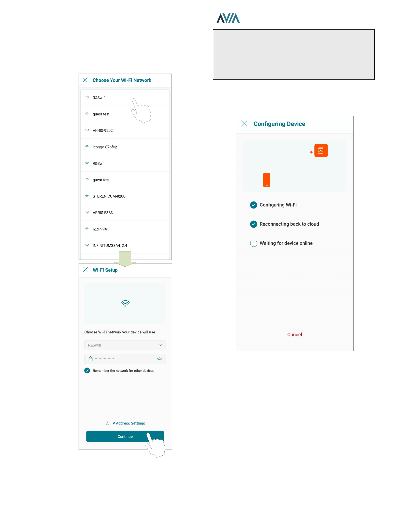
55
INSTALLATION & OPERATION MANUAL
5. The "Wi-Fi setup" screen will appear. Select or enter
the Wi-Fi network you want your unit to be connected
to and enter the network password. See Figure 85.
6. Press the "Continue" button to proceed with unit
connection.
Figure 85. Wi-Fi Setup
IMPORTANT: Raymote Wi-Fi module works with 2.4GHz
Wi-Fi signals only.
Ensure to have a strong signal near the Heater, the Wi-Fi
password and to use a 2.4 GHz network.
(IEEE 802.11, 802.11b/g/n/ax).
7. Raymote app will provide the Wi-Fi credentials to
your unit. This process may take a few seconds. See
Figure 86.
Figure 86. Conguring Device
8. Continue in page 58 to AVIA heater setup.
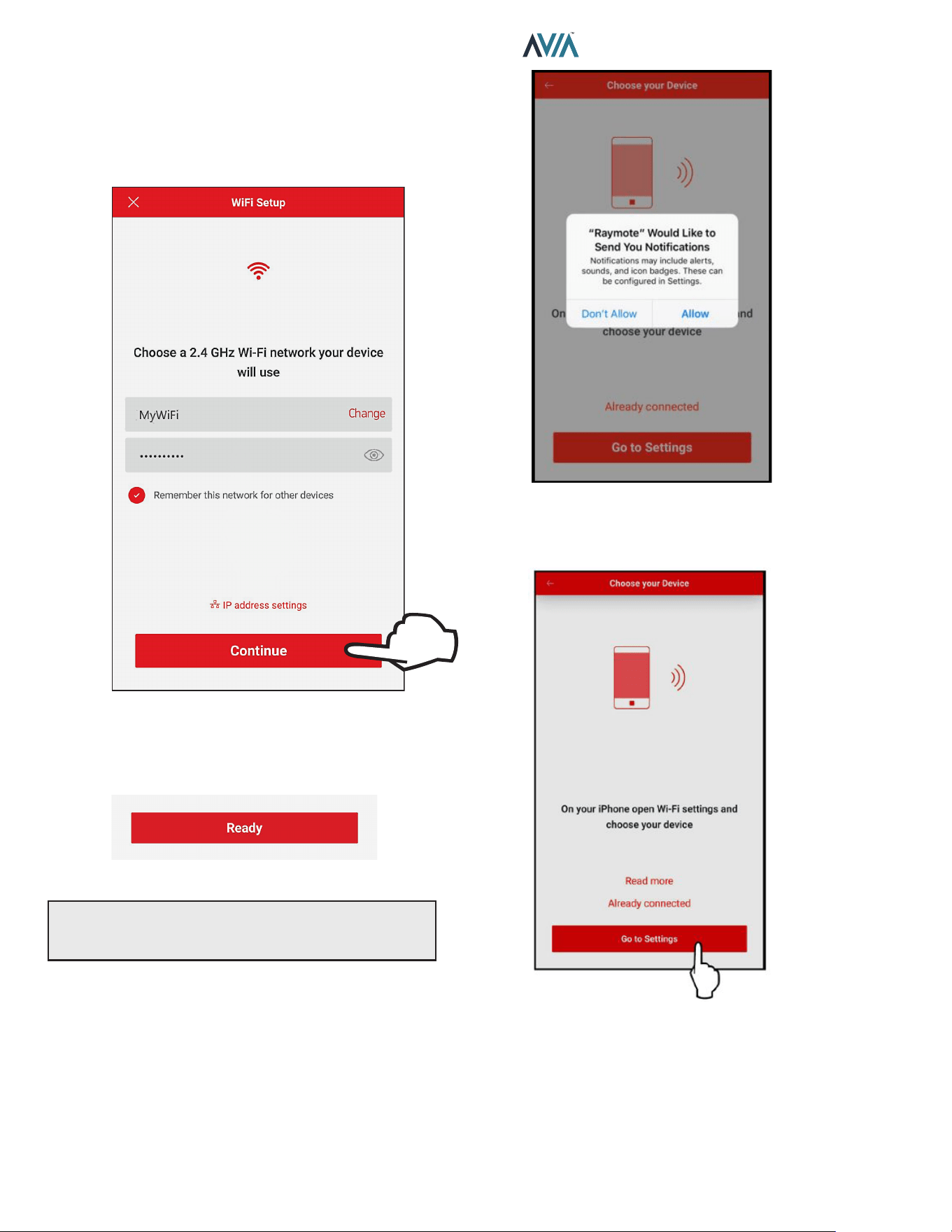
56
INSTALLATION & OPERATION MANUAL
For iPhone 6 and Earlier Versions
1. The "Wi-Fi setup" screen will appear. Select or enter
the Wi-Fi network you want your unit to be connected
to and enter the network password. See Figure 87.
2. Press the "Continue" button.
Select the HOTSPOT iden�fier that matches the unit's display as shown in
Figure 87. Wi-Fi Setup
3. "Check your Device" screen will appear. Ensure to
have AVIA heater powered and Wi-Fi signal available
in the area, then press the "Ready" button.
Figure 88. Check your Device
NOTE: The rst time you use a new phone, the Raymote
mobile app will require you grant permission to access
data. See Figure 89.
Figure 89. Grant Permission
4. Press the "Go to Settings" button on the "Choose
your Device" screen. See Figure 90.
Figure 90. Go to Settings
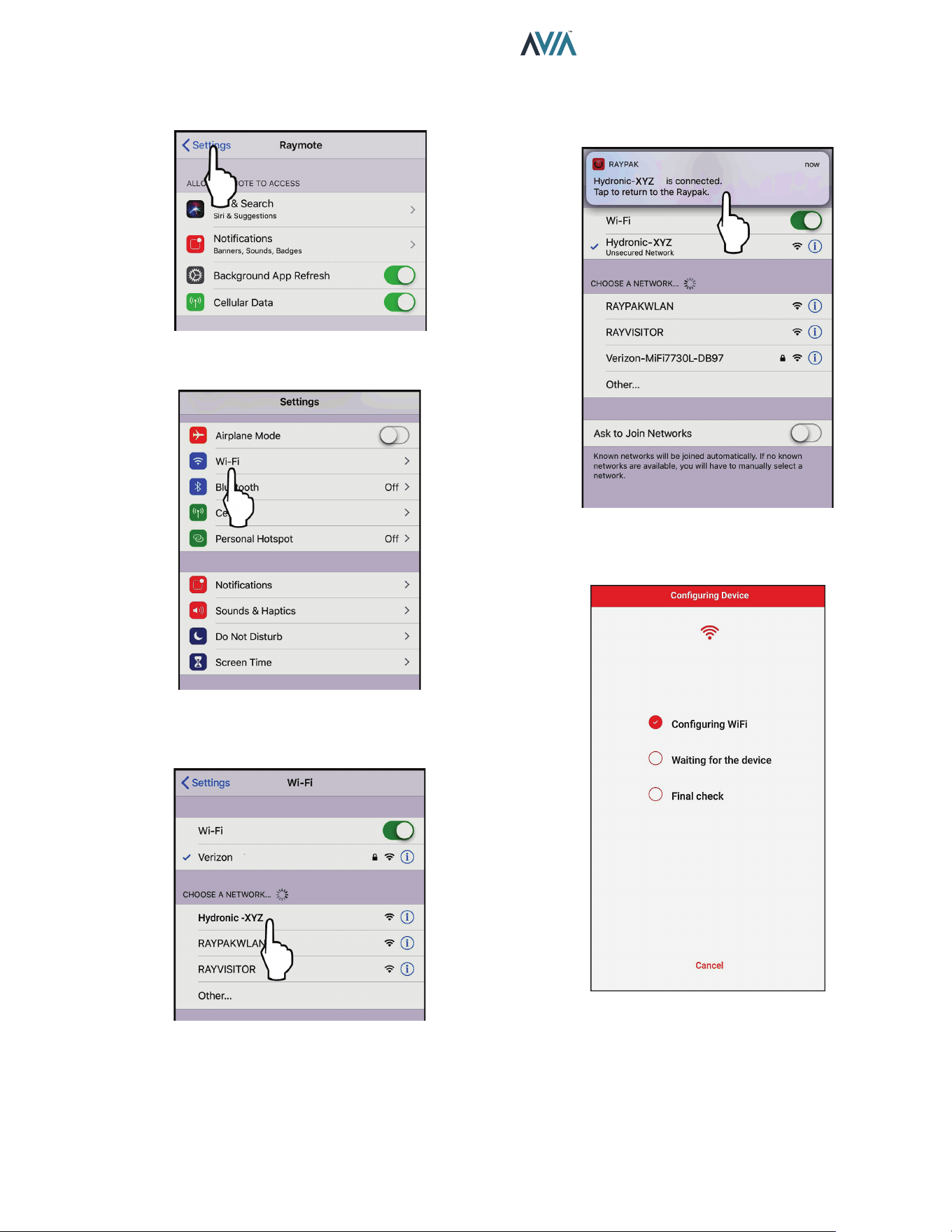
57
INSTALLATION & OPERATION MANUAL
5. On the top left corner of the screen, press the
"Settings" button to go the Settings menu. See
Figure 91.
Figure 91. Select "Settings" Menu
6. Select the Wi-Fi network on the Settings menu.
Figure 92. Select "Wi-Fi" Settings
7. Select the HOTSPOT identifier that matches the
unit’s Touchscreen as shown in Figure 93.
Figure 93. Select the HOTSPOT Identier
8. A notification tab will confirm that iPhone is now
connected to the unit. Press the notification tab or
manually go back to the Raymote mobile iPhone app
to continue. See Figure 94.
Figure 94. Connection Notication
9. The Raymote mobile app will provide the Wi-Fi
network credentials to your unit.
Figure 95. Conguring Device
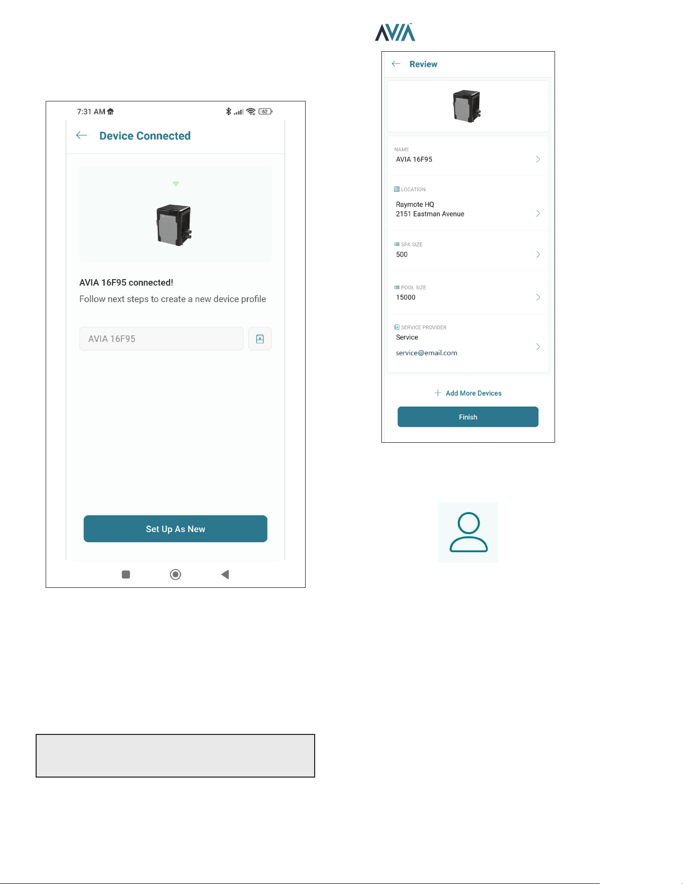
58
INSTALLATION & OPERATION MANUAL
AVIA Heater Setup
1. Your device is now connected to Wi-Fi. You can
change the name of your device here. See Figure 96.
Figure 96. Name Your Unit
2. Press the "Set up as new" button to enter heater
location, and other helpful info for future references.
Press the "Apply recently used profile" button to use
information previously applied to other heaters.
3. During device configuration, basic reference
information about the heater will be requested,
including service provider, site location, Pool and
Spa size. See Figure 97.
NOTE: This information can be added at any time from
the Raymote mobile app. It is strongly recommended to
make sure this information is completed.
4. After completing the Raymote configuration, the unit
will start broadcasting data to the Raymote cloud.
Figure 97. Device Setup Review
12. RAYMOTE MOBILE APP
User and Organization Settings
1. User profile
• Update your username, email, or password.
• Edit or delete your Raymote account.
2. Raymote App settings
• Adjust app preferences for notifications and
appearance.
3. Organization Settings
• Review and Update your Raymote organization
settings.
• Add, edit, or remove Members with access to your
Raymote organization.
• For Raymote client accounts, share access to your
Raymote organization with a Contractor with an
active Raymote Partner account.
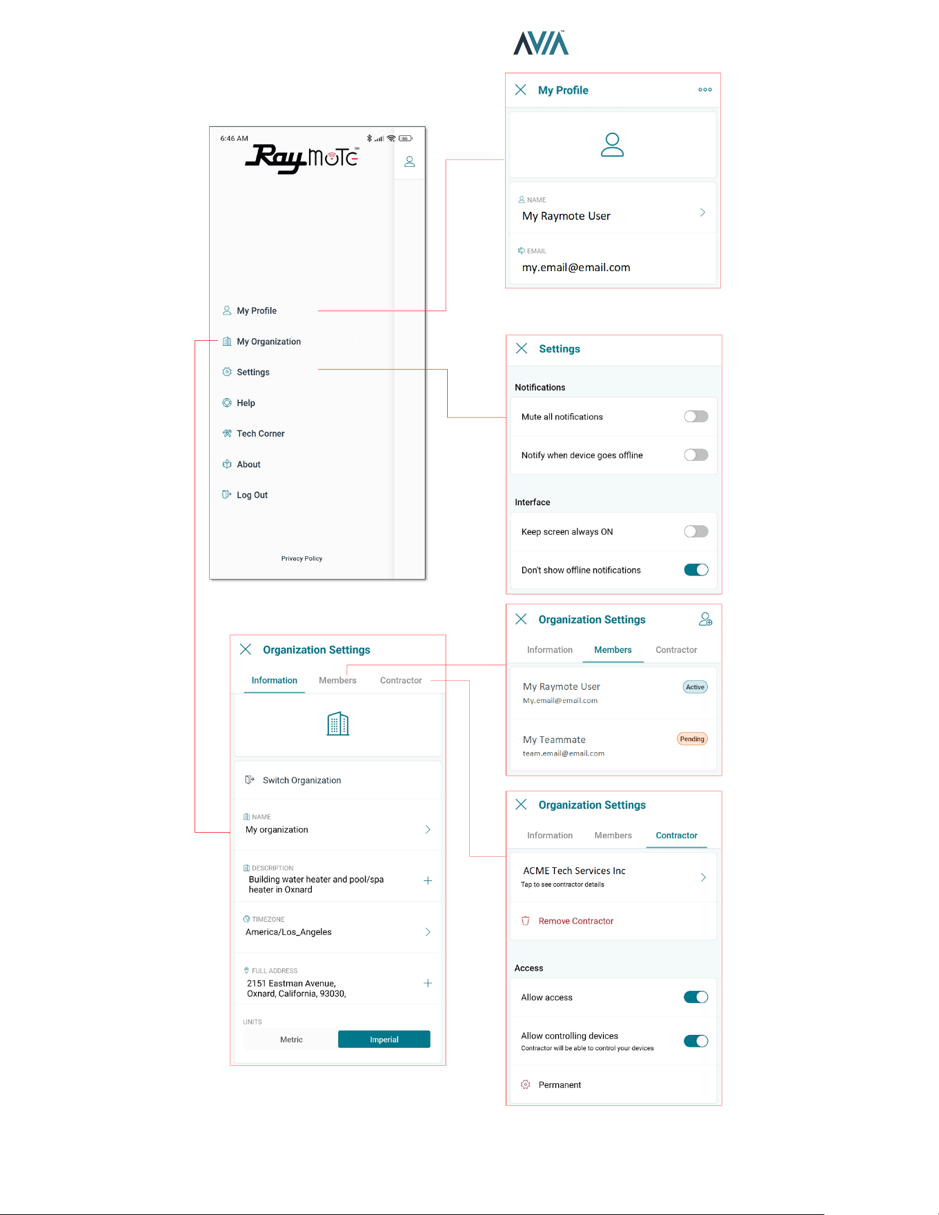
59
INSTALLATION & OPERATION MANUAL
Figure 98. Settings - Client Accounts
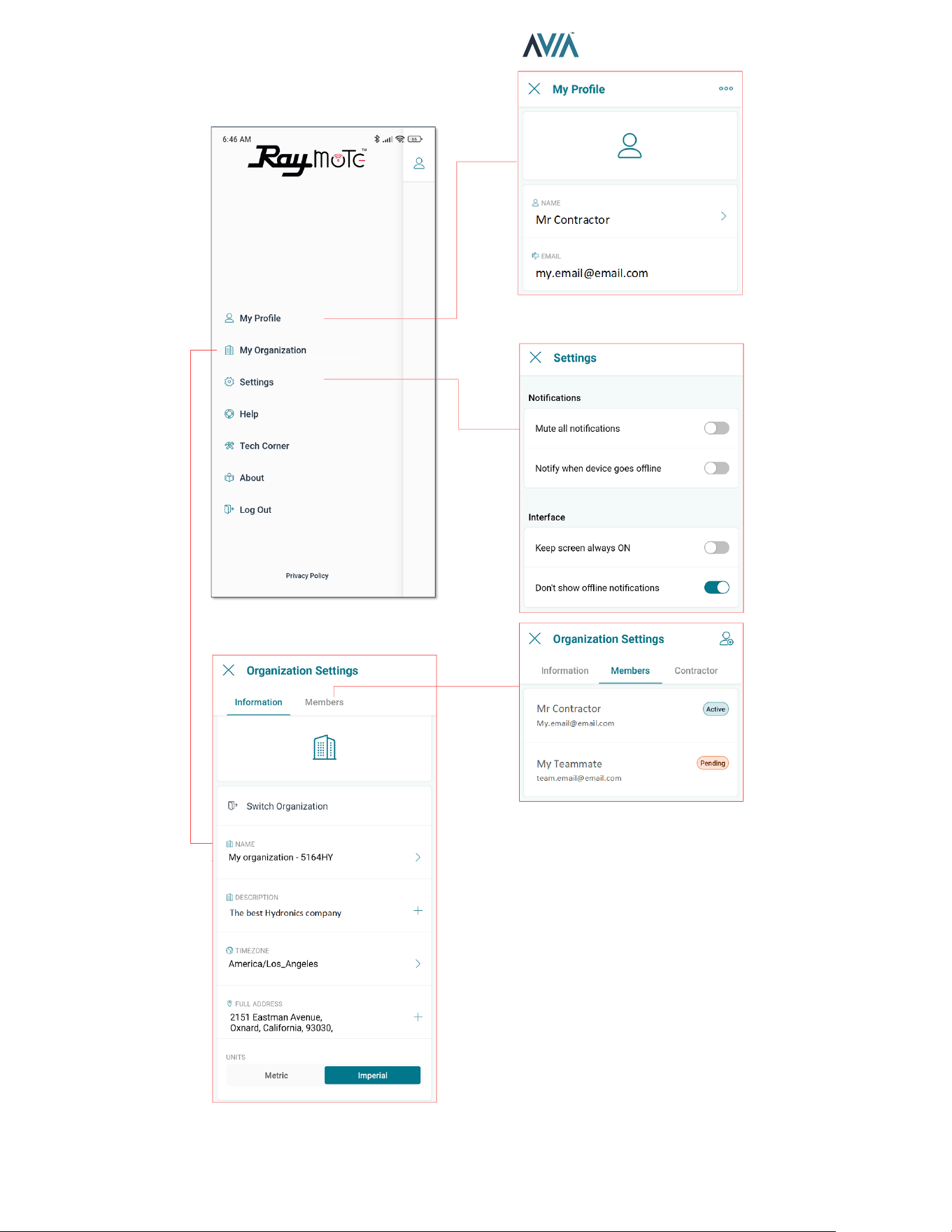
60
INSTALLATION & OPERATION MANUAL
Figure 99. Settings - Partner Accounts
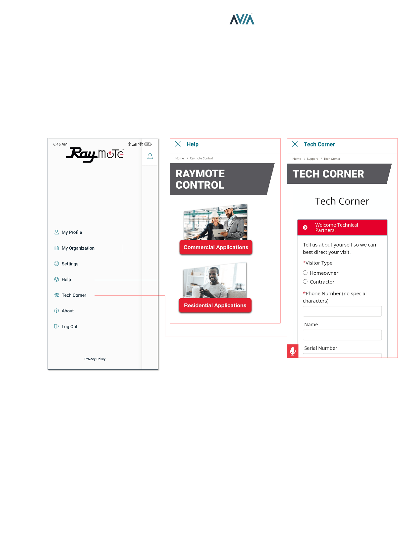
61
INSTALLATION & OPERATION MANUAL
Help and Tech Support
Raymote App provides direct access to technical
support for Raypak heaters, service kits, I&O manuals
and Raymote topics:
1. Raymote Help
• In-App access to Raymote Online resources and
technical contents.
2. Tech Corner
• In-App access to Raypak Tech Corner collection.
You can find here detailed instructions for Raypak
products and service kits.
Figure 100. Help and Tech Support
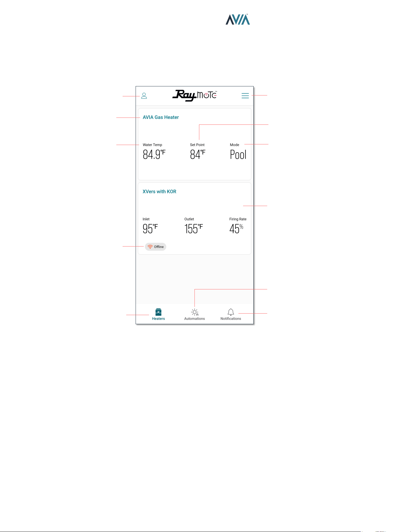
62
INSTALLATION & OPERATION MANUAL
Main View
• The main view of Raymote display a list of the heaters
added in to your Raymote Organization.
• Each heater is represented by a tile with its name and
an overview of the heater operation parameters.
USER AND ORGANIZATION
SETTINGS
ADD HEATERS AND
SORTING
HEATER LIST CAN
INCLUDE COMMERCIAL
HEATERS
OPENS NOTIFICATIONS
SCREEN
OPENS AUTOMATION
SCREEN
HEATERS SCREEN
HEATER OFFLINE
INDICATOR
CURRENT WATER
TEMPERATURE
HEATER NAME
HEATER MODE
SELECTION
WATER TEMPERATURE
TARGET
Figure 101. Main View - Heaters List
• Raymote organization list can handle 1 or multiple
Commercial and Residential Raypak heaters
equipped with Raymote.
Heater Name
• Heater name is defined during the Heater connection
and setup, but it can be changed anytime from the
heater settings.
Water Temp
• The water temperature measured by the heater is
displayed in this field. Water Temp variates with the
ambient temperature, pumps and heaters operation.
Setpoint
• Setpoint is the goal temperature for the heater. It can
be adjusted from the AVIA control board or directly
from Raymote.
• Heater start a call for hear when Water Temp is 1
degree Fahrenheit or more, below the setpoint and
operation Mode is POOL or SPA.
• Heater terminate heat when Water Temp is equal or
greater the setpoint temperature, or when Mode is
changed to OFF.
Mode
• Mode field displays the current operation mode
selected.
• POOL mode use an independent setpoint.
• SPA mode use an independent setpoint.
• In OFF mode the heater is operational but is maintained
in standby until mode changes to POOL or SPA.
Oine Indicator
• The offline indicator is displayed only when the Heater
can not be detected online.
• Offline status can be cause by a heater disconnected
from power, Wi-Fi signal weak or not available, or due
to any change in Wi-Fi signal name or password.
• Check the Connectivity Troubleshooting section for
details on how to recover or reconnect a heater to
Raymote.
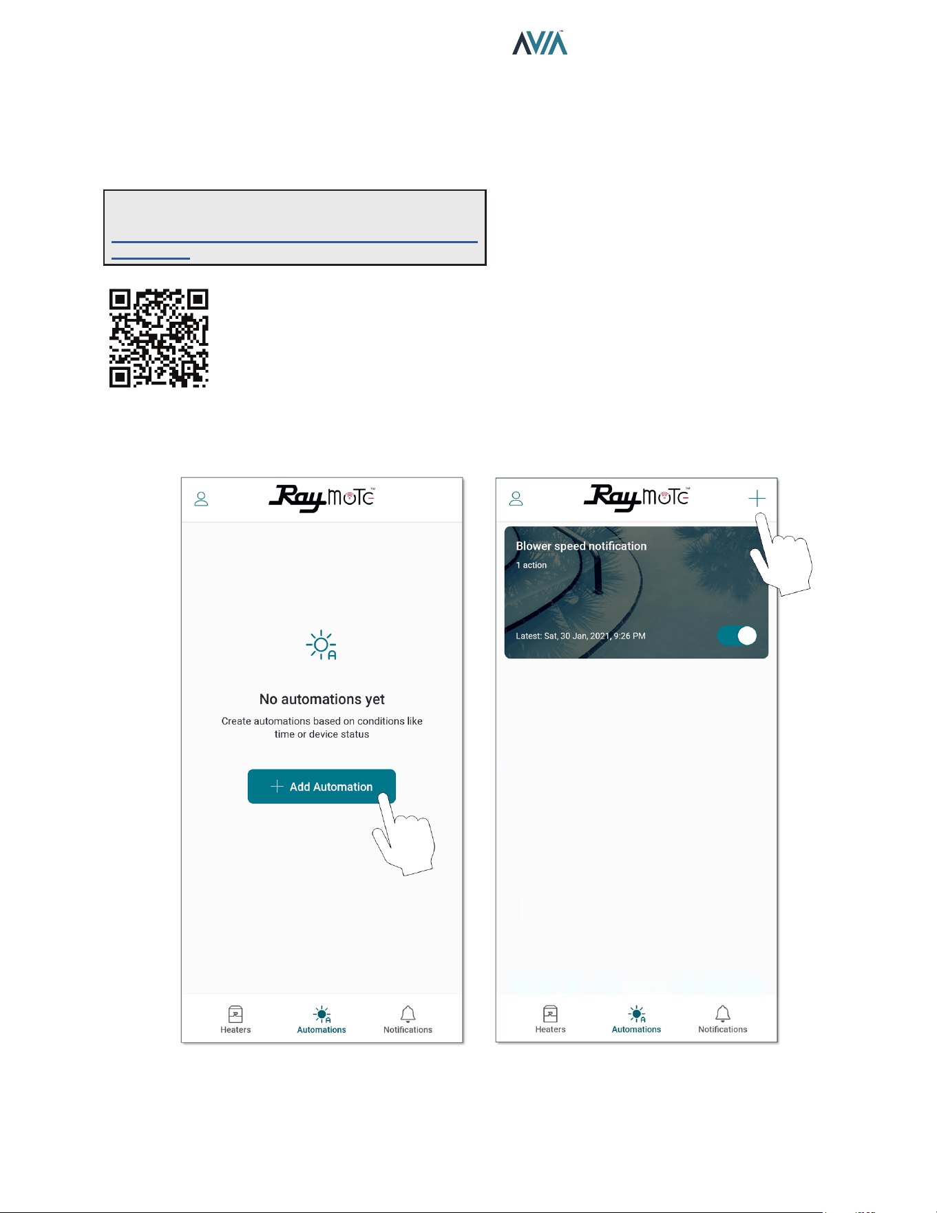
63
INSTALLATION & OPERATION MANUAL
Automation
Raymote automation oers the ability to select Heater
parameters and customize a specic condition that could
trigger a notication or an action to update a parameter.
See Figure 102 and Figure 103.
Figure 102. Automation
NOTE: Use your smartphone camera to access detailed
instructions for Auxiliary output scheduling with Raymote.
https://www.raypak.com/support/tech-corner/raymote-
automation/
ADD THE FIRST AUTOMATION ADD MORE AUTOMATIONOR
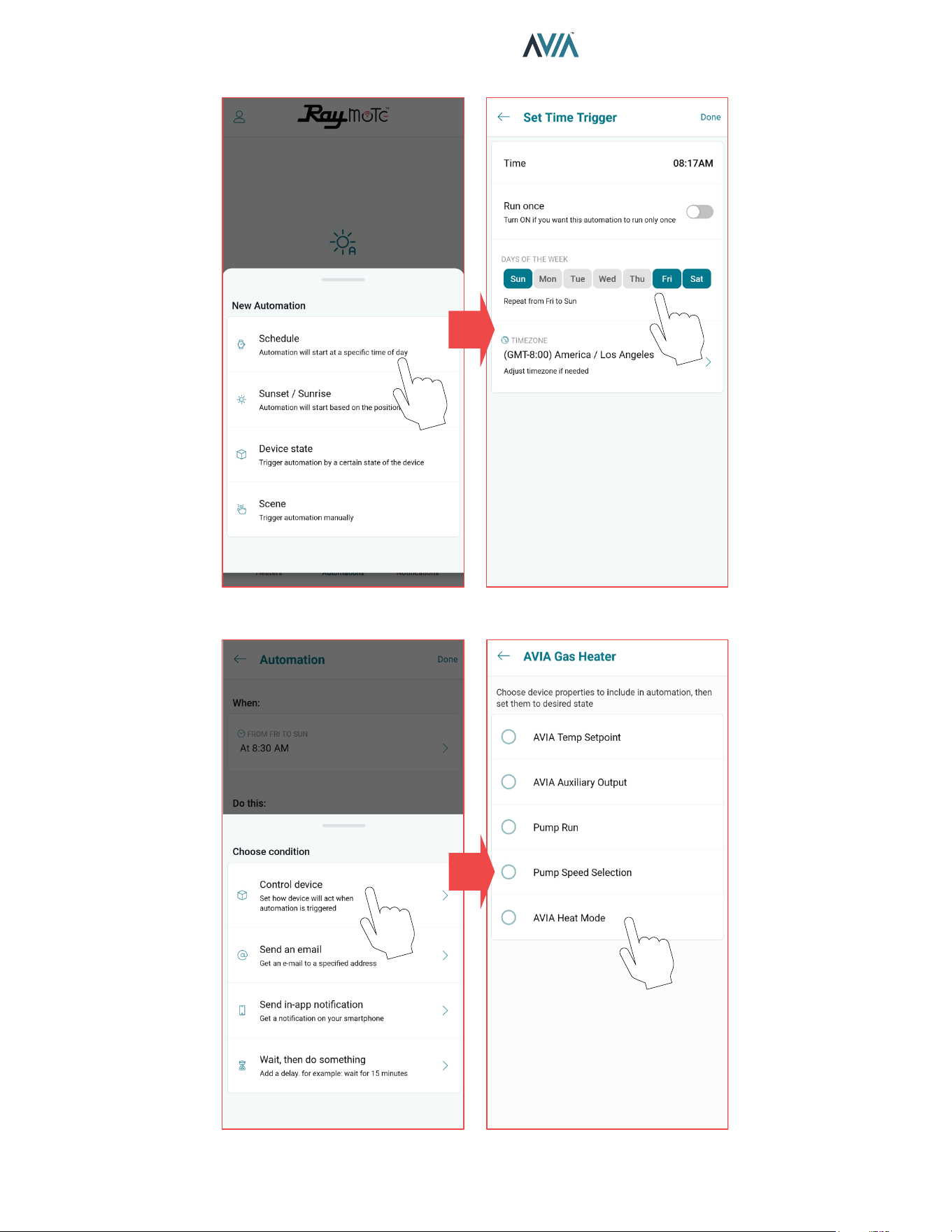
64
INSTALLATION & OPERATION MANUAL
Figure 103. Set New Automation
SELECT A TRIGGER CONFIGURE TRIGGERING
SELECT AN ACTION CONFIGURE THE ACTION
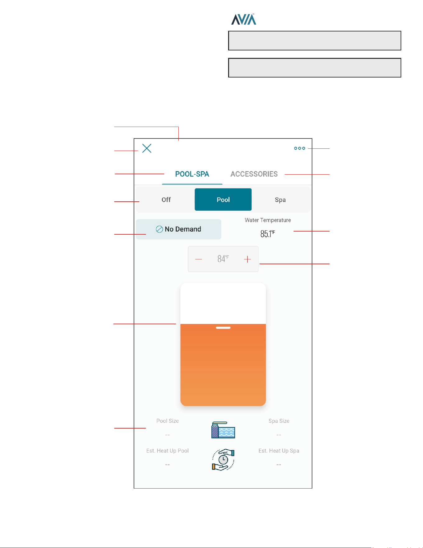
65
INSTALLATION & OPERATION MANUAL
Pool-Spa Mode Screen
The Mode Screen contains the main controls for the
heater. Operation mode and setpoint can be selected from
this screen.
This screen also provides the water temperature sensed
by the heater, as well as its current operation status. See
Figure 104.
Figure 104. AVIA Controls
OPERATION MODE
SELECTOR
POOL-SPA PAGE
WATER
TEMPERATURE
HEATER STATUS
EXIT HEATER
HEATER SETTINGS
POOL AND SPA SIZE
& HEATING TIME
ESTIMATION
HEATER NAME
WATER
TEMPERATURE
TARGET DISPLAY
AND SELECTOR
WATER
TEMPERATURE
TARGET SELECTOR
ACCESSORIES PAGE
AVIA Pool & Spa Gas Heater
NOTE: When OFF is selected, the setpoint slider is
disabled.
NOTE: When the unit is controlled with remote mode,
the OFF, Pool and Spa buttons are disabled in the App.

66
INSTALLATION & OPERATION MANUAL
Heater Name
• Heater name is defined during the Heater connection
and setup. It can be changed anytime from the Heater
settings.
Exit Heater
• Press X to close Heater view and return to heaters list.
Heater Settings
• The 3-dot icon opens Heater settings.
• Use this option to edit the parameters defined during
heater configuration.
POOL-SPA page
• Displays the page to control the operation mode and
water temperature target.
ACCESSORIES page
• Displays the page to control Heater Accessories.
Operation Mode selector
• This 3-button selector can be used to change the
operation mode in the Heater.
• Use OFF option to stop heating. In this mode the
heater is operational but is maintained in standby until
mode changes to POOL or SPA.
• Use POOL or SPA mode to set a Water Temperature
target.
• POOL and SPA mode use an independent temperature
target for each mode.
Heater Status
• This display shows the current operational status of
heater.
• No Demand is displayed when the unit is in OFF mode
or when Water Temperature is equal or above the
temperature target.
• Pre-Purge is displayed when a new heating cycle
starts and the heater is getting prepared for ignition.
• Spark is displayed during the ignition trial.
• Heating is shown when unit has established a solid
flame and the unit is heating.
• Post-Purge is displayed when the demand-for-heat is
terminated and unit is getting cooled down.
Water Temperature
• The water temperature measured by the heater is
displayed in this field.
Setpoint or Target Temperature
• The water temperature setpoint display and selector
shows the water temperature target.
• Heater start to hear when Water Temperature is 1
degree Fahrenheit or more, below the setpoint and
operation Mode is POOL or SPA.
Setpoint slider selector
• The setpoint slider can be used to make quick changes
to the water temperature target.
• Selection can be fine-tuned with the [+] and [-] buttons
in the setpoint display and selector.
Pool and Spa size
• The Pool and Spa size displays shows the size
selected in the configuration of the heater when
connected to Raymote.
• These parameters can be updated from the Heater
Settings page.
Pool and Spa estimated Heat up time
• These fields displays an estimated heat up time based
in the provided Pool and Spa size, the current water
temperature and the water target temperature.
• Technical restrictions apply to this estimation.
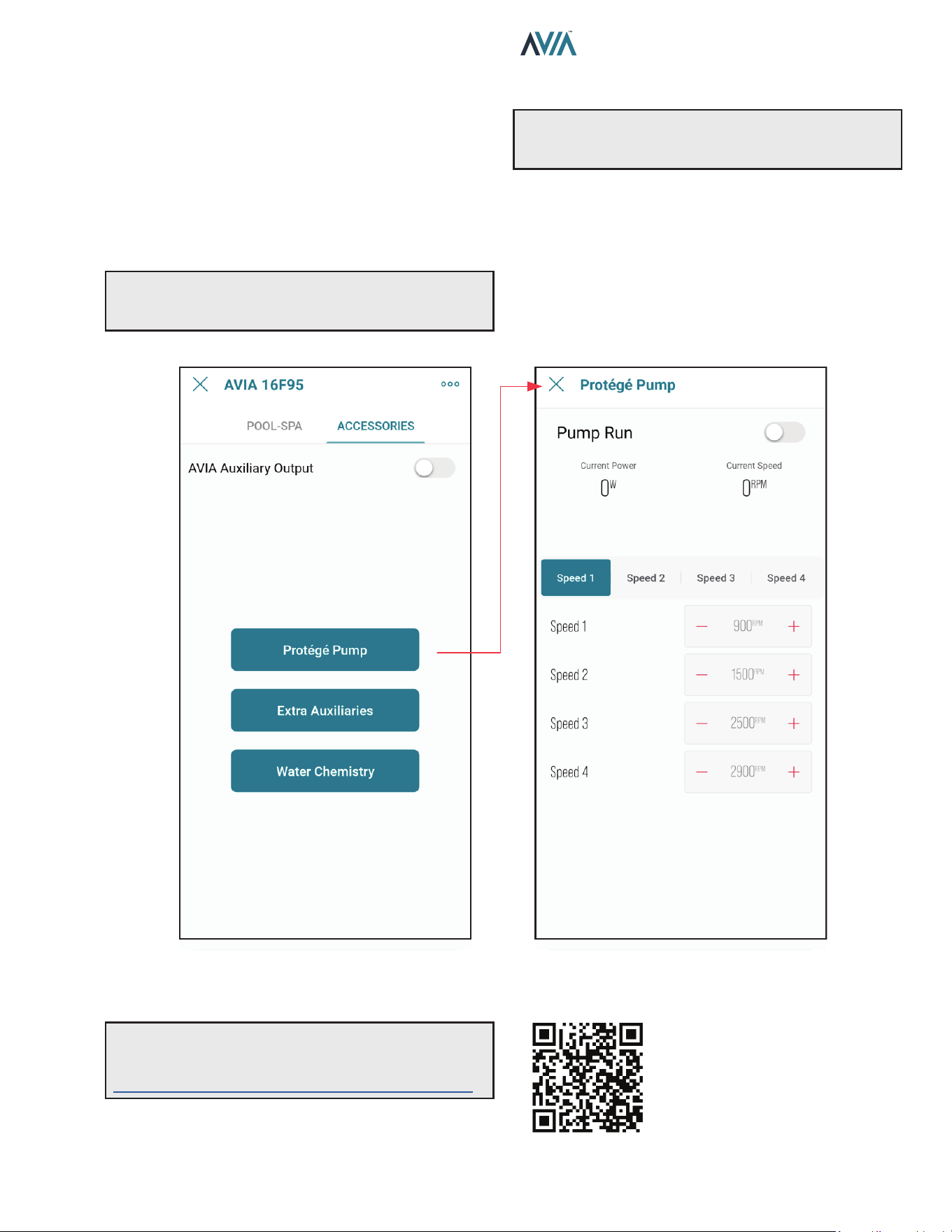
67
INSTALLATION & OPERATION MANUAL
Accessories Screen
The accessories screen includes the auxiliary and
extended heater controls in the Raymote mobile app.
These controls allow users to command an Auxiliary relay
that can be wired to turn on and o a pump, lights or water
features.
This screen also provides control to Raypak Protege
variable speed pump when connected to the heater. See
Figure 105.
Figure 105. AVIA Accessories
A
WARNING: Only authorized users have access to
remotely control the heater, do not provide credentials
to unauthorized users.
A
WARNING: Check "Auxiliary Output Control"
section for details of wiring and rating of the built-in
auxiliary relay.
Some controls are application dependent and may not be
available on all units. When a control or set of controls are
not available, these will be grayed out.
Raymote controls will reect the actual status of the value
on the local unit. When a change is applied to any control
item, the position of the selector will reect the conrmation
value of the setting. See Figure 105.
NOTE: Use your smartphone camera to open QR
link below to access the latest instructions and
detailed technical support for Raymote and AVIA:
https://www.raypak.com/support/tech-corner/raymote/
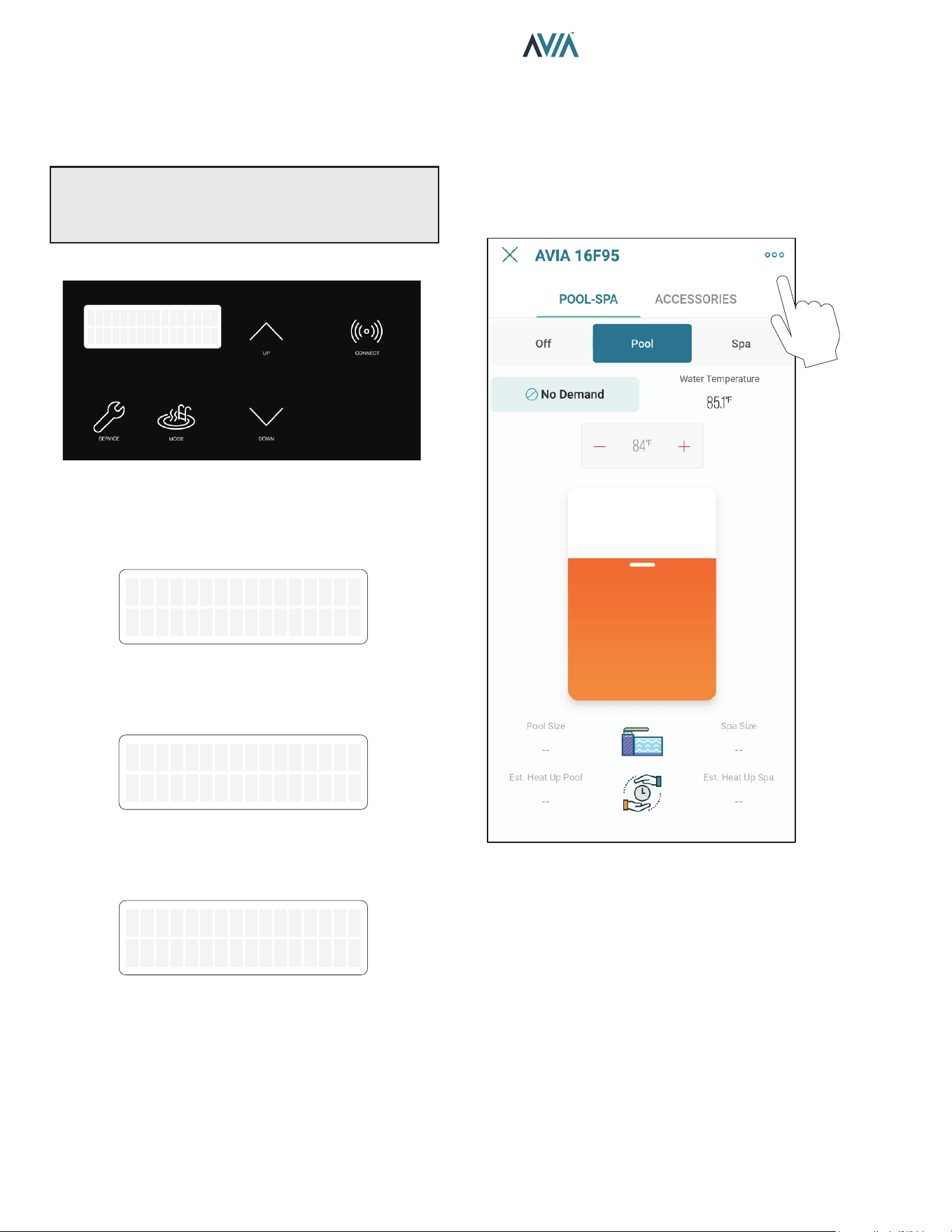
68
INSTALLATION & OPERATION MANUAL
Reset Wi-Fi Credentials
Resetting the Wi-Fi is useful when the heater is trying to
connect to a Wi-Fi signal that is not available or has been
changed.
NOTE: After resetting Wi-Fi credentials, the heater
needs to be manually connected again to Wi-Fi to work
with Raymote features. Ensure to reconnect as existing
unit in Raymote app or add it as a new device.
1. Press and hold the CONNECT key for 5-seconds.
OFF
Water Temp 68F
Figure 106. Wi-Fi Reset – Press and Hold CONNECT
2. The Display shows “Reset Wi-Fi?” In the top row and
“No” in the second row.
3. To cancel and exit, press MODE.
Reset WiFi?
No
Figure 107. Wi-Fi Reset Menu
4. To proceed with reset, press UP key.
5. Second row now shows “Yes".
Reset WiFi?
Yes
Figure 108. Wi-Fi Reset Conrmation
6. Now press Mode key to reset.
7. “Wi-Fi Initialized” message is displayed.
WiFi Initialized
Figure 109. Wi-Fi Reset Completed
8. Now Connect again or reconfigure an existing heater.
Reconnect to Wi-Fi
Follow the next steps to reconnect a Heater already
registered in Raymote, to a new Wi-Fi network or after a
change of Wi-Fi password.
1. Select the device that needs to be reconfigured.
2. Press the 3-dots button on top-right corner to open
unit settings.
Figure 110. Open Unit Settings
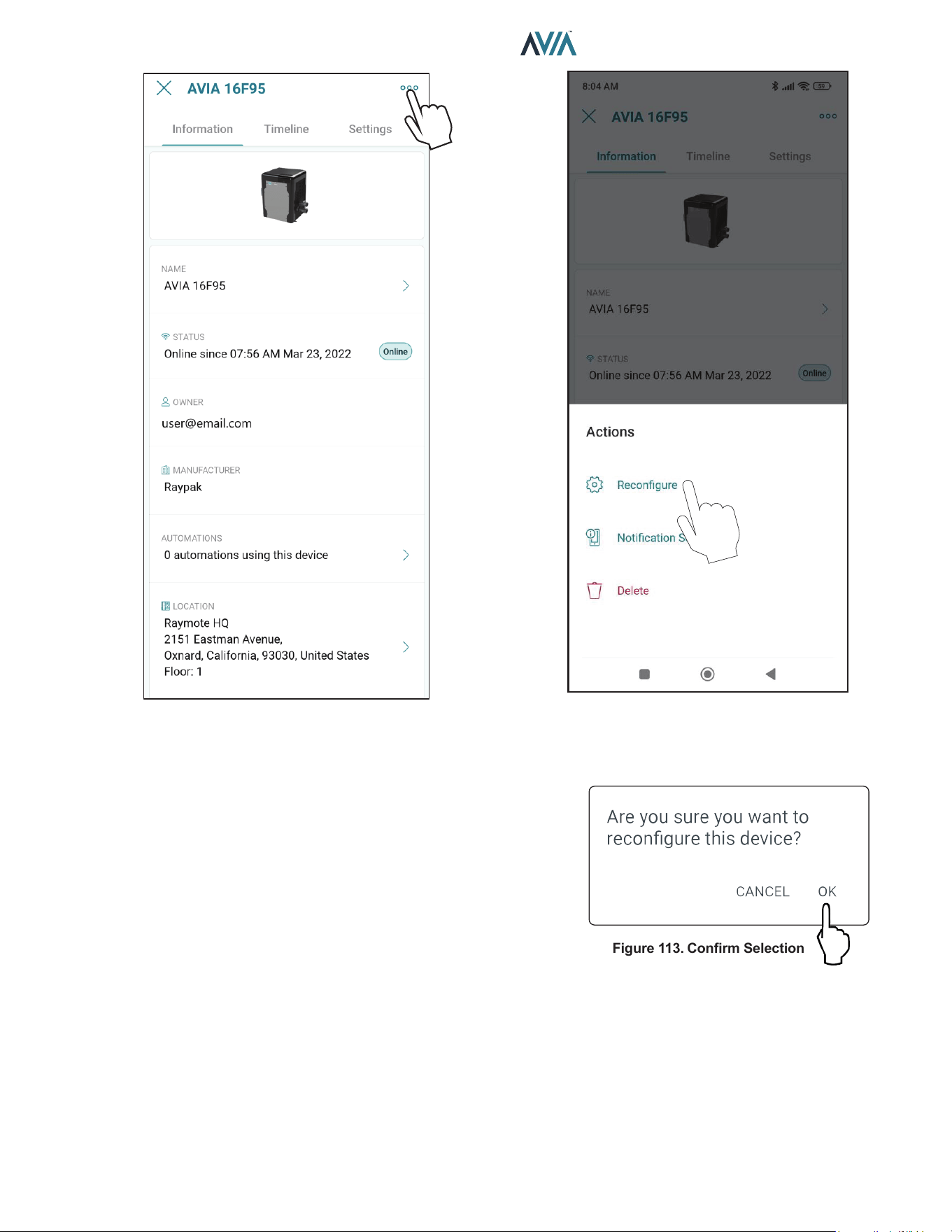
69
INSTALLATION & OPERATION MANUAL
Figure 111. Heater Settings Screen
3. Click in the 3-dots icon again. The action menu is
displayed. In “Actions” menu, select the option
“Reconfigure”.
Figure 112. Select Recongure
Figure 113. Conrm Selection
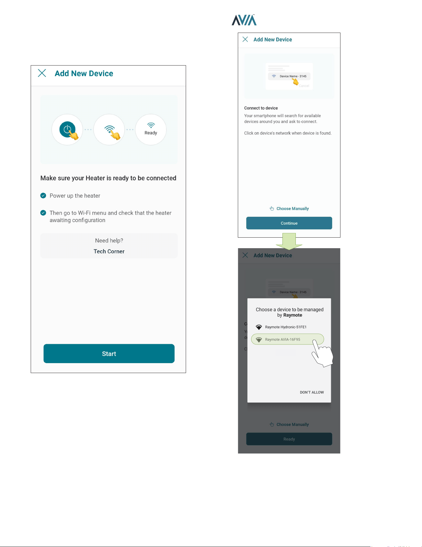
70
INSTALLATION & OPERATION MANUAL
4. "Check your Device" screen will appear. Ensure to
have the heater powered and Wi-Fi signal available
in the area, then press "Ready" button. See Figure
114.
Figure 114. Check your Unit
5. In Android: Depending on your configuration, one
or more devices will appear on the app. Select the
HOTSPOT identifier that matches the unit's display
as shown in Figure 115.
Figure 115. Connect with Android Smart Phone
6. In iPhone: Raymote app will start to scan nearby
Heaters. If you have multiple units ready to connect,
stand closer to the unit you want to connect first.
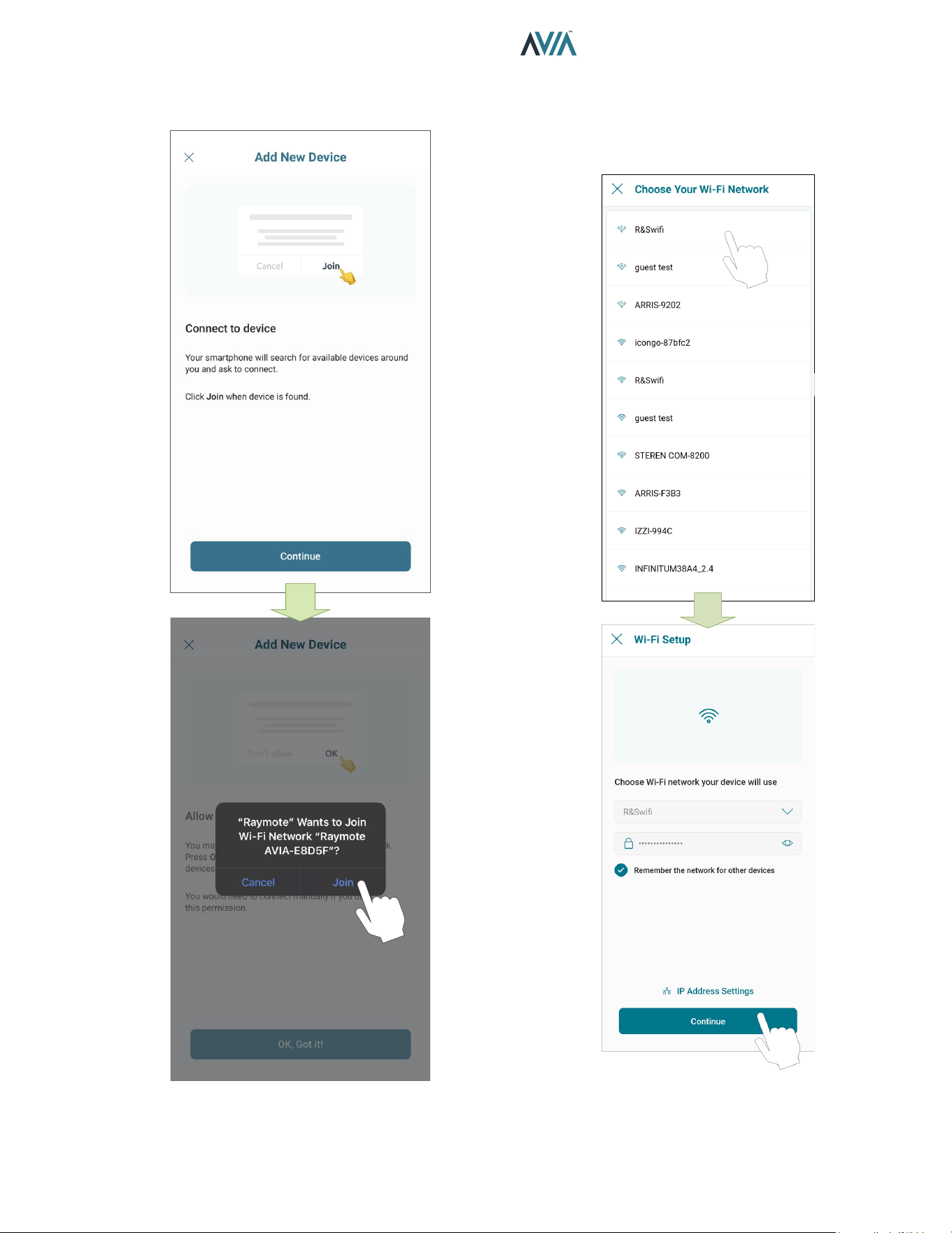
71
INSTALLATION & OPERATION MANUAL
Press "Join" to select the displayed heater that
matches the HOTSPOT identifier, or press "Cancel"
to start the process again. See Figure 116.
Figure 116. Connecting with iPhone
7. The "Wi-Fi setup" screen will appear. Select or enter
the Wi-Fi network you want your unit to be connected
to and enter the network password. See Figure 117.
8. Press the "Continue" button to proceed with unit
connection.
Figure 117. Wi-Fi Setup
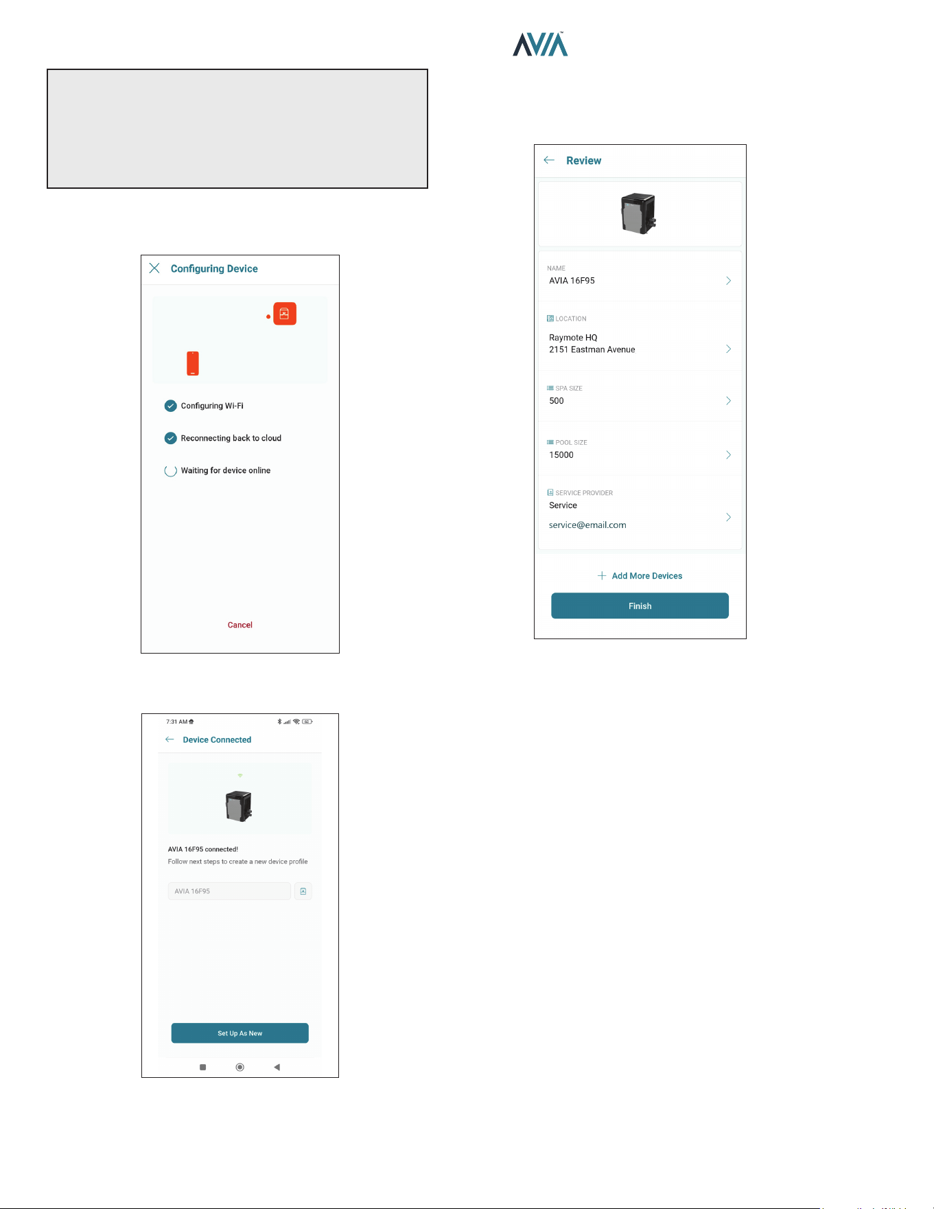
72
INSTALLATION & OPERATION MANUAL
IMPORTANT: Raymote Wi-Fi module works with 2.4GHz
Wi-Fi signals only.
Ensure to have a strong signal near the Heater, the Wi-Fi
password and to use a 2.4 GHz network.
(IEEE 802.11, 802.11b/g/n/ax).
9. Raymote app will provide the Wi-Fi credentials to
your unit. This process may take a few seconds. See
Figure 118.
Figure 118. Conguring Device
10. Your device is now connected to Wi-Fi.
Figure 119. Name Your Unit
11. Press the "Set up as new" button to enter unit
location, and other helpful info for future references.
Press the "Apply recently used profile" button to use
information previously applied to other heaters.
Figure 120. Device Setup Review
12. After completing the Raymote configuration, the unit
will start broadcasting data to the Raymote cloud.
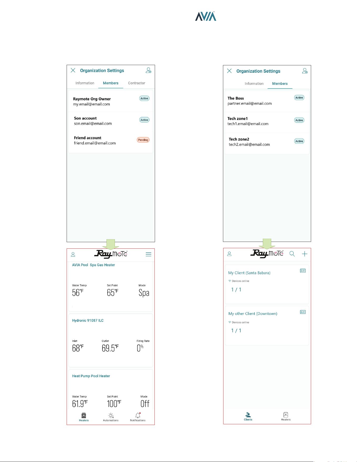
73
INSTALLATION & OPERATION MANUAL
Add a New User to your Organization
• As the Organization owner, you can add members of
your family, friends and others that will be able to interact
with your Heaters.
Figure 121. Organization Members Share Access to Heaters Figure 122. Partners Accounts with Multiple Clients
• In Raymote Partner accounts, you can add members
of your company to gain access to Heaters and Clients
registered within your Organization.
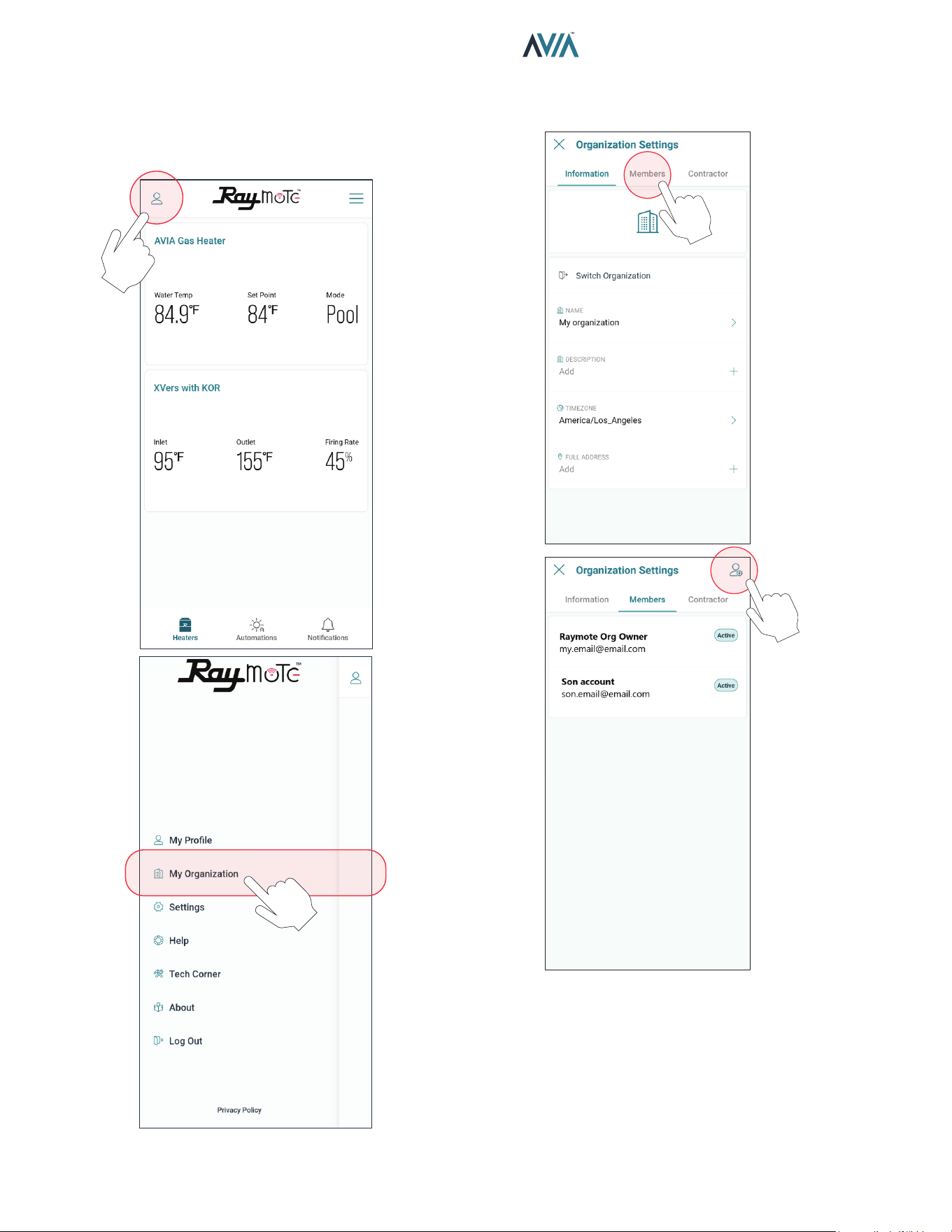
74
INSTALLATION & OPERATION MANUAL
Figure 123. Select Organization Option
Figure 124. Invite a New Member to your Organization
Add a Member to your Organization
1. In your smartphone open Raymote app.
2. Click on top-left "User menu". Then, select "My
Organization" option.
3. Go to "Members" tab. Member’s list is displayed.
4. Click on the top-right icon to [Invite a New Member].
5. Fill the invitation with new member's email, name,
and role. Based on your selection, the new member
can have different permits in your organization.
6. Click in the top-right icon to complete and send the
invite. An email will be sent to the New Member
to create a new Raymote user associated to your
organization.
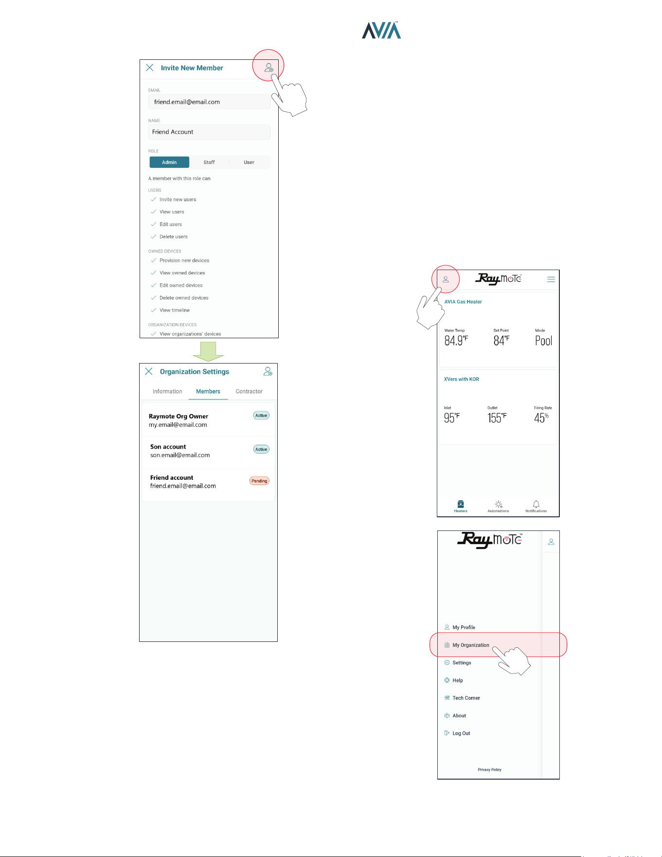
75
INSTALLATION & OPERATION MANUAL
7. IMPORTANT: To complete the invitation, the
new member needs to create a password from
Raymote email invitation, to access your Raymote
Organization.
Figure 125. Invite a New Member
Client Accounts: Invite a Contractor
By inviting a Contractor or Distributor, you are giving
access to Heaters available in your organization to a third-
party organization.
You can condition the access to your invited contractor as
follows:
• For monitoring only.
• To monitor and control your heaters.
o Access can be permanent or restricted to a certain
period.
1. In your smartphone, open Raymote App.
2. Click on top-left "User menu".
3. Then, select "My Organization" option.
Figure 126. Select Organization Option
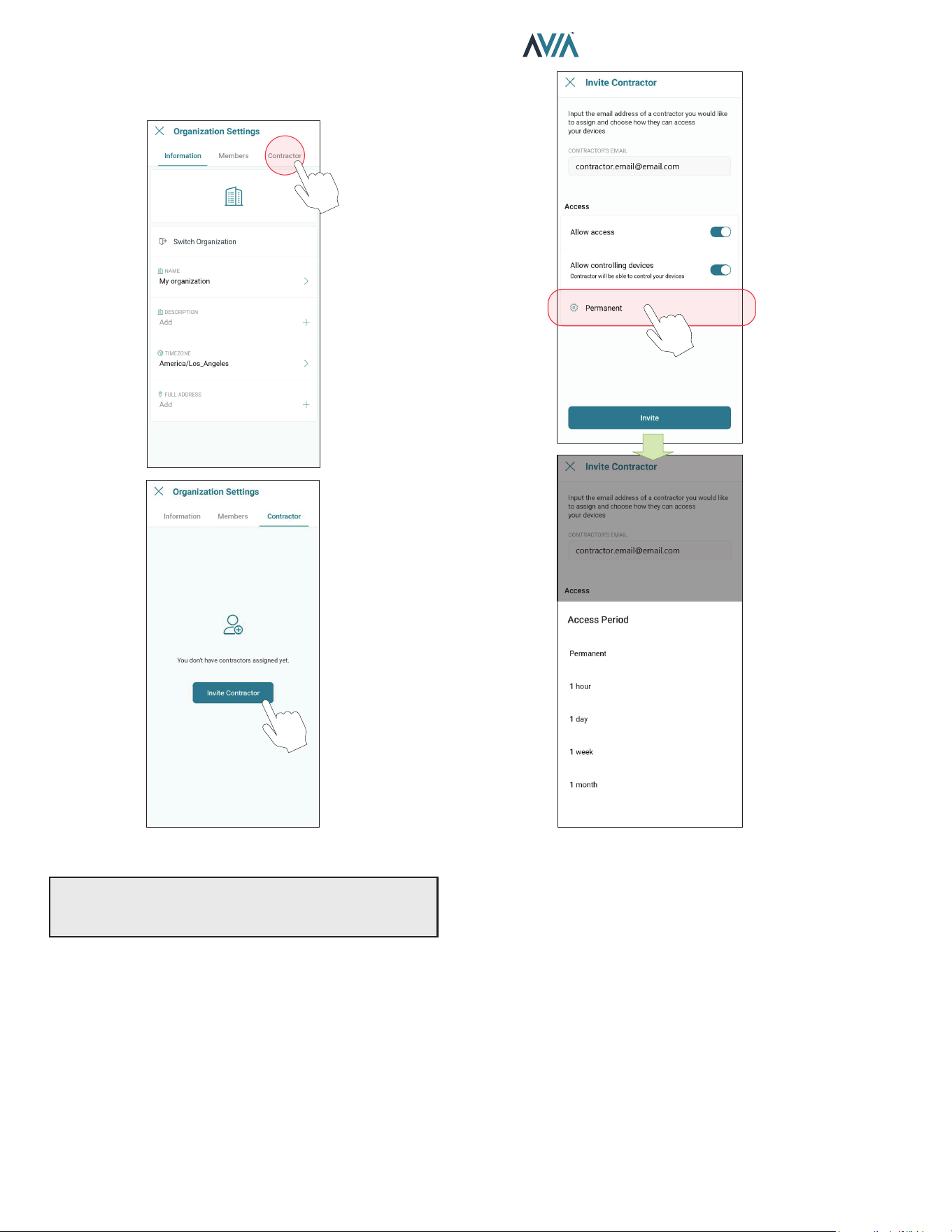
76
INSTALLATION & OPERATION MANUAL
Figure 127. Click on “Invite Contractor” Figure 128. Enter Contractor Email and Access Level
4. Organization Settings page is displayed.
5. Go to [Contractor] tab, and press [Invite Contractor].
6. Add your contractor’s email and select the access
options as needed:
• Allow access - Allows the contractor to monitor your
heaters.
• Allow controlling device - Contractor can make
changes to your heater conguration and create
automation routines.
• Access Period - Denes for how long the contractor
can monitor or interact with your heaters.
7. When ready, press [Invite]. An invitation/request will
be sent to the contractor's Raymote account. When
ready, press [Invite]. An invitation/request will be
sent to the contractor's Raymote account.
8. IMPORTANT: To complete the invitation process ask
your contractor to accept the request directly from
their Raymote App account.
9. When done, you can always edit the permissions,
remove the contractor, or cancel the invitation in
Organization’s settings, [Contractor] page.
IMPORTANT: Contractor must have an active Raymote
“Partner” account to be able to connect your account
with the contractor’s account.
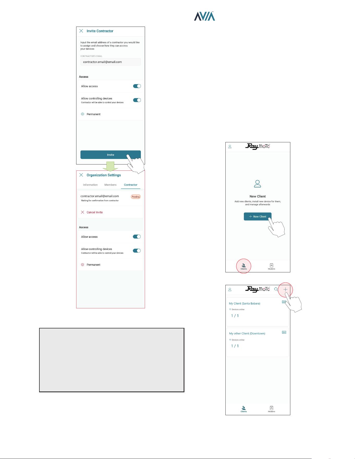
77
INSTALLATION & OPERATION MANUAL
Figure 129. Send the Invite
NOTES:
•“Invite a contractor” option is only available for Raymote
Client accounts.
•Contractor must have a Raymote Partner account to get
requests from Client accounts.
•Raymote Partner accounts can invite only new clients
to Raymote. If the client already has a Raymote account,
ask the client to send a request from “Contractor” option.
Partner Accounts: Invite new Clients
With a Raymote Partner account, “Contractor” or “Distributor”,
you can:
•Invite and Manage New Clients
•Connect and congure your clients' heaters
•Monitor and Control Residential and Commercial
heaters
•Create automation Routines and Alerts for your clients
•Invite Members to your Organization
1. In your smartphone, open Raymote App.
2. Click on bottom-left [Clients] icon.
3. Now, press [New Client] button or top-right [+] icon.
OR
Figure 130. Add a New Client to Raymote and your
Organization
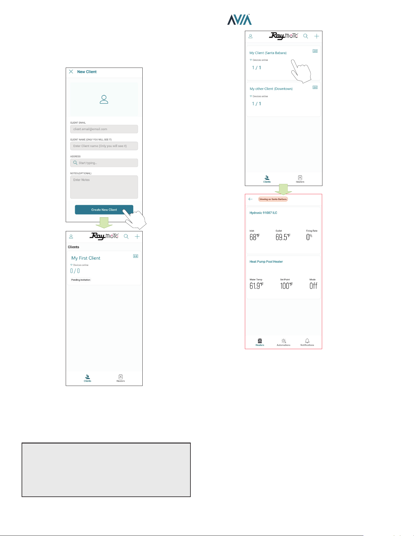
78
INSTALLATION & OPERATION MANUAL
Figure 131. Enter Client Email and Invite
4. Fill New Client form with your client's email, name,
and address.
5. When ready, press [Create new client]. An Raymote
invite email will be sent to your new client.
6. Ask your Client to create a new Raymote account
from the email invite.
7. You can access your client's heaters by clicking in
each client tile.
OR
Figure 132. Access your Client's Heaters
NOTES:
•“Add New Client” option is only available for Raymote
Partner accounts.
•Raymote Partner accounts can invite only new clients
to Raymote. If the client already has a Raymote account,
ask the client to send a request from “Contractor” option.
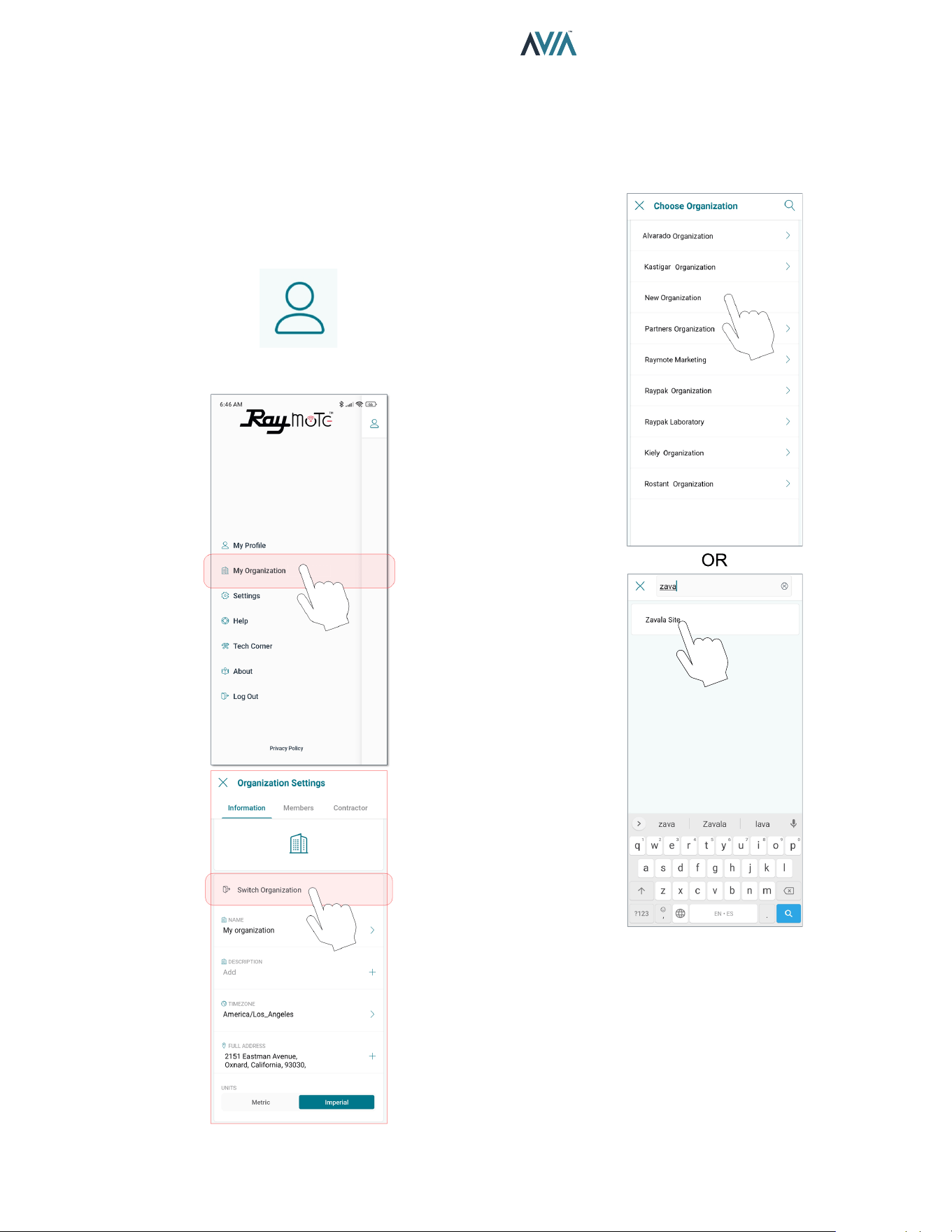
79
INSTALLATION & OPERATION MANUAL
Switch to other Organizations
If your Raymote organization has 1 or more sub
organizations, you can switch to other organization by
using the Organization tree or search function.
1. Open the main menu by clicking the top left icon. See
Figure 133.
2. On the main menu, click on the “Organization” option.
See Figure 134.
Figure 133. User Menu
Figure 134. Switch Organization
Figure 135. Choose Organization
3. In "Organization Settings" page, select "Switch
organization" option.
4. “Choose organization” screen will be displayed and it
will show all the available organizations. Navigate the
sub Organization list or use the search tool to locate
desired organization. See Figure 135.
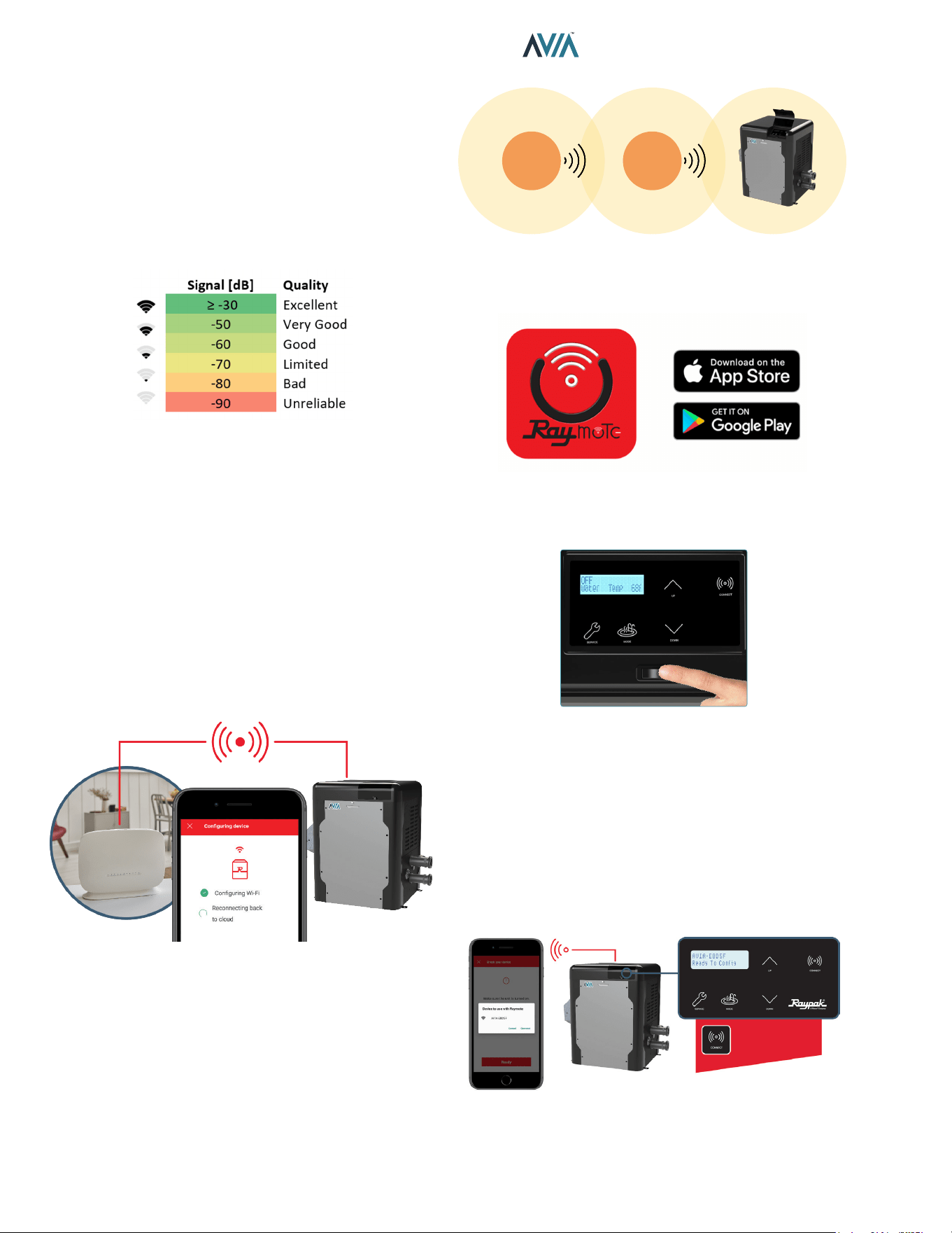
80
INSTALLATION & OPERATION MANUAL
Connectivity Troubleshooting
1. With your cellphone check that Wi-Fi signal is
available next to the unit. Ensure that your Wi-Fi
network meets these specifications:
• Supported Networks - Wi-Fi 2.4GHz (802.11 b/g/n).
• Password encryptions - WEP, WPA, WPA2.
• Wi-Fi signal icon of 2 bars (-60dB) or better at heater
location.
Figure 136. Wi-Fi Signal
Figure 137. Reset Wi-Fi Credential
2. Use the built-in Wi-Fi network options in your
cellphone or use a Wi-Fi network scanner app like
Fing Network Scanner for iPhone or Wi-Fi Analyzer
for Android smart phones, to check signal strength.
If you are having troubles connecting your Heater to
the Raymote app, try these common solutions:
• Check that Wi-Fi signal name and password are
correct.
• In case of a change, proceed to Reset Wi-Fi credential
from Heater Touchscreen and reconnect the heater
with Raymote app.
3. Check that your Wi-Fi signal strength is strong
enough to reach the heater.
• Reduce distance between Wi-Fi router and the
heater.
• Add a Wi-Fi range extender to cover heater zone or
enable a new Wi-Fi access point.
Wi-Fi
Router
Wi-Fi
Extender
Figure 138. Wi-Fi Extender
4. Update Raymote app to the latest version.
Figure 139. Update Application
5. Power-cycle your heater and restart Raymote app.
Figure 140. Restart Raymote
6. Check the settings on your router or Wi-Fi access
point.
• If needed, enable a dedicated 2.4 GHz network.
5GHz signals are not compatible with Raymote.
• When applicable, ensure to have the permissions
from IT or Building manager.
• Check if MAC address whitelisting is required.
• Check if Static IP is required.
The CONNECT key
displays the ID and
connectivity status.
Figure 141. Wi-Fi Access Point Settings
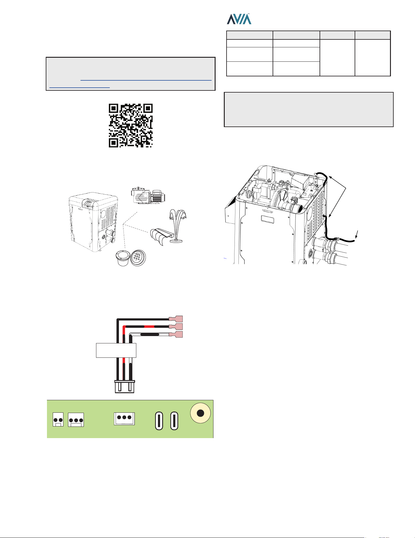
81
INSTALLATION & OPERATION MANUAL
13. AUXILIARY CONTROL
OUTPUT
The AVIA heater oers an integrated dry contact relay for
local and remote control of ON/OFF devices like pumps,
water features, valves and lights.
PUMPS
WATER FEATURES
LIGHTS
Figure 142. Device Relay Integration
Auxiliary output is available in terminal P9 “AUX”. Use the
supplied harness to control ON/OFF functions or power
switching.
COM
NO
NC
AUXILIARY RELAY
OUTPUT
TEMP
INTPUT
TEMP
AUX
POWER BLOWER
P2 P1 P9
Figure 143. Auxiliary Terminal
AUX terminal can be used as direct control or as pilot
relay to a higher rating relay or power contactor. Table S
describes Auxiliary output terminals and ratings.
Terminal Wire AC Rating DC Rating
Common Black
250V Max,
3A
30V Max,
3A
Normally Open Black and Red
Normally Closed Black and White
Table S. Auxiliary Terminals and Ratings
A
CAUTION: Do not exceed Auxiliary relay rating.
Check power requirements of any electric component
connected to this device, following the applicable
installation norms and requirements.
Use the knockout holes located next to water inlet panel to
route auxiliary harness inside the cabinet to the controller
board. See Figure 144.
ROUTE HARNESS
FROM KNOCKOUT
TO CONTROL BOARD
TO AUXILIARY
DEVICE
Figure 144. Route Communication Harness
It is recommended to use a 1/2" NPT liquid tight cord grip
inserted in the panel knockout hole for better sealing.
NOTE: Use your smartphone camera to access detailed
instructions for Auxiliary output scheduling with
Raymote. https://www.raypak.com/support/tech-corner/
raymote-automation/
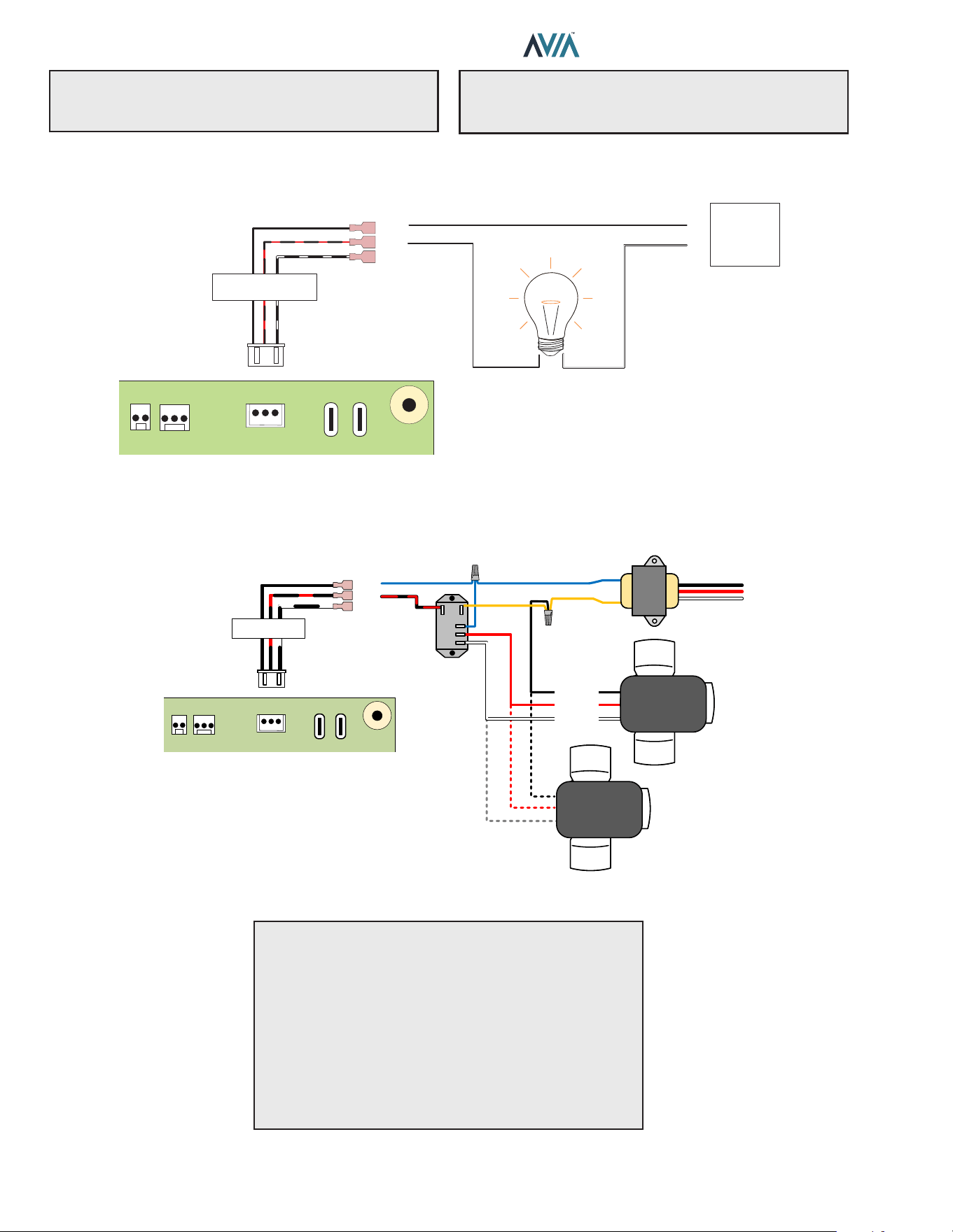
82
INSTALLATION & OPERATION MANUAL
The built-in Auxiliary output (P9) is a dry-contact relay output that can be used as a switch to control valves, lights and
other devices.
EXTERNAL
POWER
SUPPLY
COM
NO
NC
AUXILIARY RELAY
OUTPUT
TEMP
INTPUT
TEMP
AUX
POWER BLOWER
P2 P1 P9
+
-
Figure 145. Auxiliary Relay
Use the Normally Closed (NC) and Normally Open (NO) terminals to drive a 3-way valve. This conguration typically
uses an external 24 VAC supply.
POSITION 1
POSITION 2
COMMON
COM
NO
NC
AUXILIARY RELAY
OUTPUT
TEMP
INTPUT
TEMP
AUX
POWER BLOWER
P2 P1 P9
AUXILIARY RELAY
INTPUT
TEMP
AUX
POWER BLOWER
P2 P1 P9
USE WITH A SPDT OR DPDT 24VAC RELAY
USE AN EXTERNA 24VAC
TRANSFORMER
COM
NO
NC
OUTPUT
TEMP
3-WAY VALVE
ACTUATOR
3-WAY VALVE
ACTUATOR
Figure 146. 3-Way Valve
NOTE: P9 Auxiliary is a dry contact output: It requires
external power supply to energize connected devices.
See Figure 145.
A
CAUTION: Load on P9 must not exceed 3 Amps. If
the load is larger than 3 Amps, use P9 auxiliary output to
drive a field-installed contactor. See Figure 147.
A
CAUTION: When connecting more than 1 actuator
follow these recommendations to avoid damage or
unexpected response of the equipment:
A
While adjusting the cams of an actuator, disconnect
the other actuators to avoid energizing them in inverse
polarization.
A
After individually adjusting each actuator, and before
energizing the circuit, ensure all the actuators have the
"position" switch in the same setting. Having mixed
settings may cause electrical damage to the actuators.
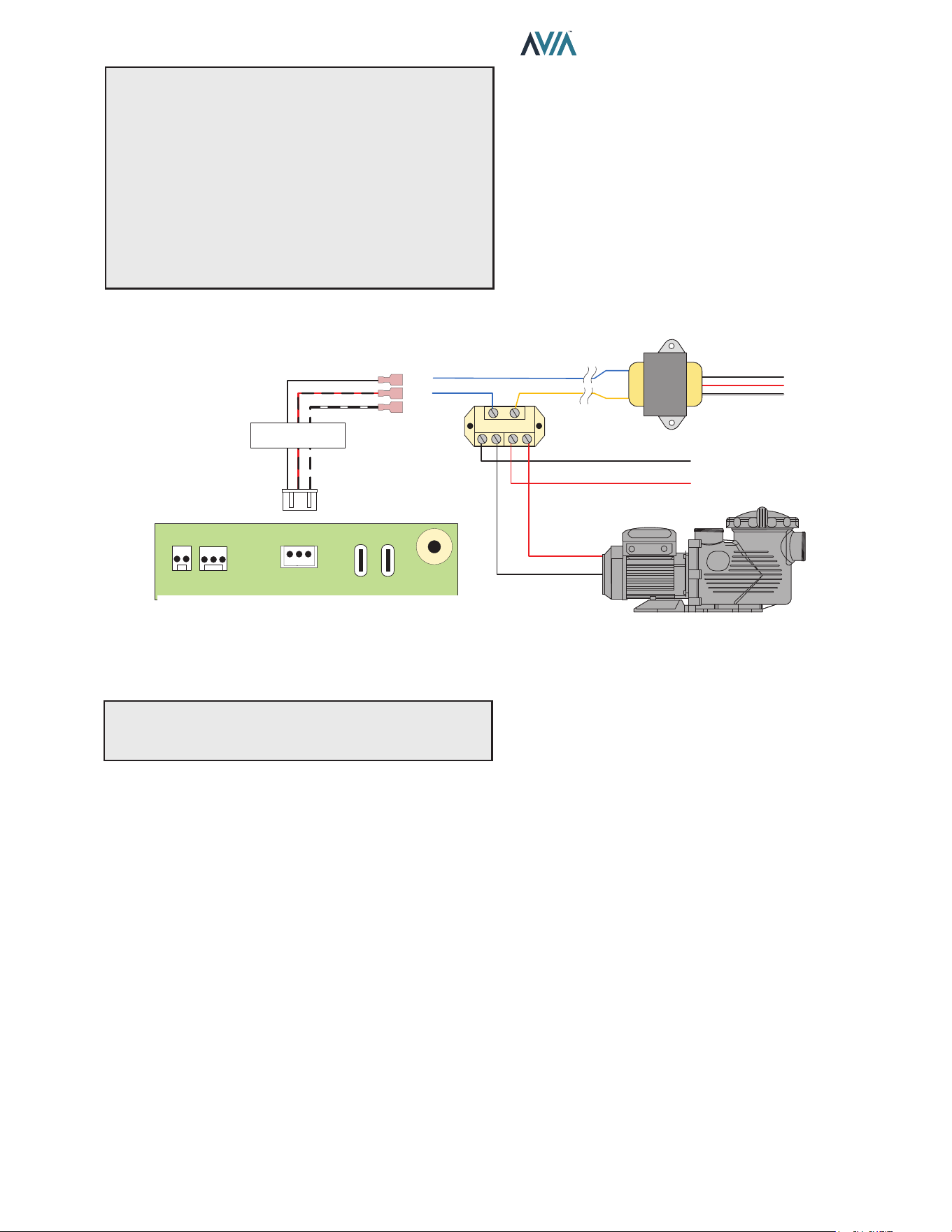
83
INSTALLATION & OPERATION MANUAL
NOTE: Ensure to select proper relay coil voltage
and terminal current rating per your application.
●
Always check the voltage specication of the
eld-supplied relay. Check coil activation voltage.
●
When using power from the 24V AC transformer,
ensure to use a relay with coil voltage for 24V AC.
●
If a dierent voltage is required to activate the relay
coil, ensure to use the proper power supply instead of
the 24V AC transformer.
14. REPLACEMENT PARTS
NOTE: To supply you with the correct part, it is important
that you supply the heater model number, serial number
and type of gas when applicable.
Any part returned for replacement under standard company
warranties must be properly tagged with a return parts tag,
completely lled in with the heater serial number, model
number, etc., and shipped to the Company freight prepaid.
If determined defective by the Company and within
warranty, a like part or equal substitution will be returned,
freight collect. Credit will not be issued.
MANUFACTURER:
Av. New York 207, Parque Industrial Oradel, C.P.
88285 Nuevo Laredo Tamps. Mexico
120V OR 240V PUMP
LINE 1
LINE 2 OR NEUTRAL
COM
NO
NC
AUXILIARY RELAY
OUTPUT
TEMP
INTPUT
TEMP
AUX
POWER BLOWER
P2 P1 P9
24V AC
IN OUT IN OUT
Figure 147. High Power Applications with Field-Supplied Relay
For single-speed pumps, blowers and other applications rated above 3 Amps, use field-supplied DPST relay.
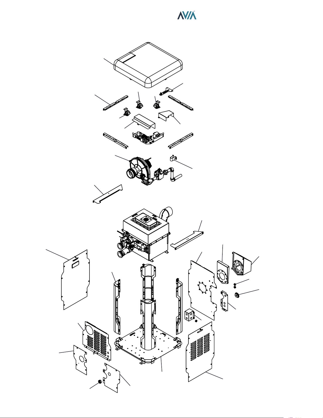
84
INSTALLATION & OPERATION MANUAL
15. ILLUSTRATED PARTS LIST
3-S
1-M
1-C
6-C
4-C
5-G
2-M
6-S
1-S
2-S
4-S
1-G
18-S
13-S
16-S
17-S
14-S
9-S
11-S
10-S
12-S
8-S
15-S
3-M
9-M
5-C
18-S
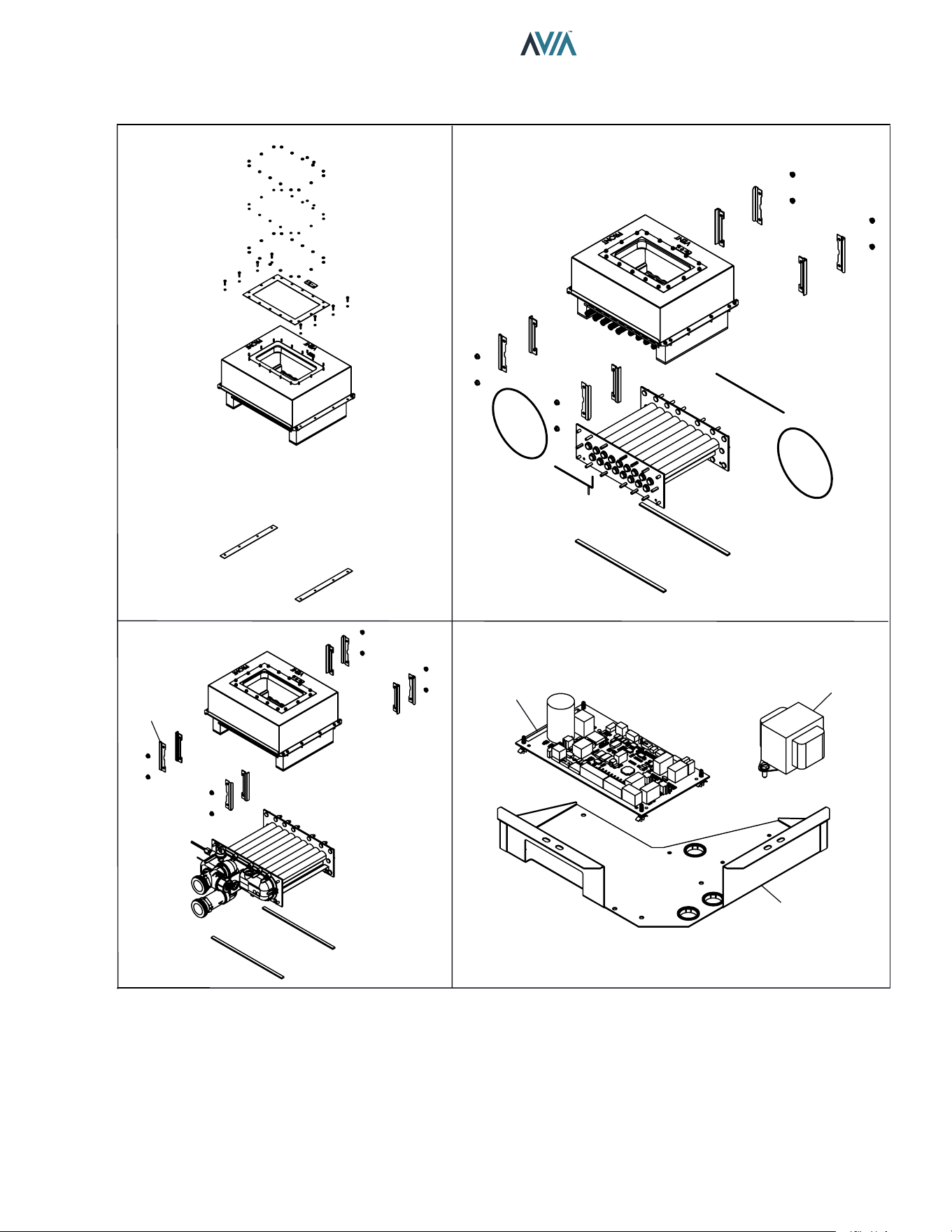
85
INSTALLATION & OPERATION MANUAL
2-H
1-R
1-H
7-S
2-C
3-C
5-S
REFRACTORY ASSY. TUBE BUNDLE
HEAT EXCHANGER IGNITION BOARD & TRANSFORMER
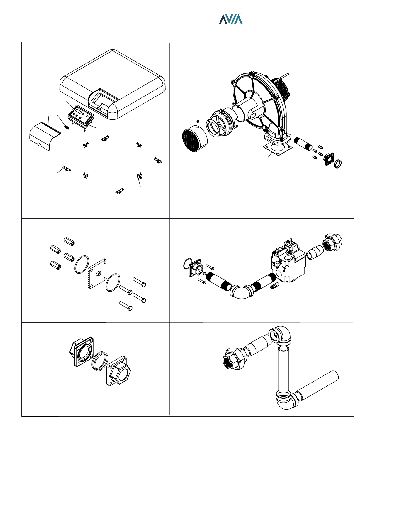
86
INSTALLATION & OPERATION MANUAL
1-F
2-F
2-G
1-M
4-M
5-M
6-M
7-M
8-M
10-M
6-G
3-G
4-G
TOP COVER ASSY. BLOWER ASSY.
GAS ORIFICE GAS VALVE
GAS ORIFICE ADAPTER GAS LINE
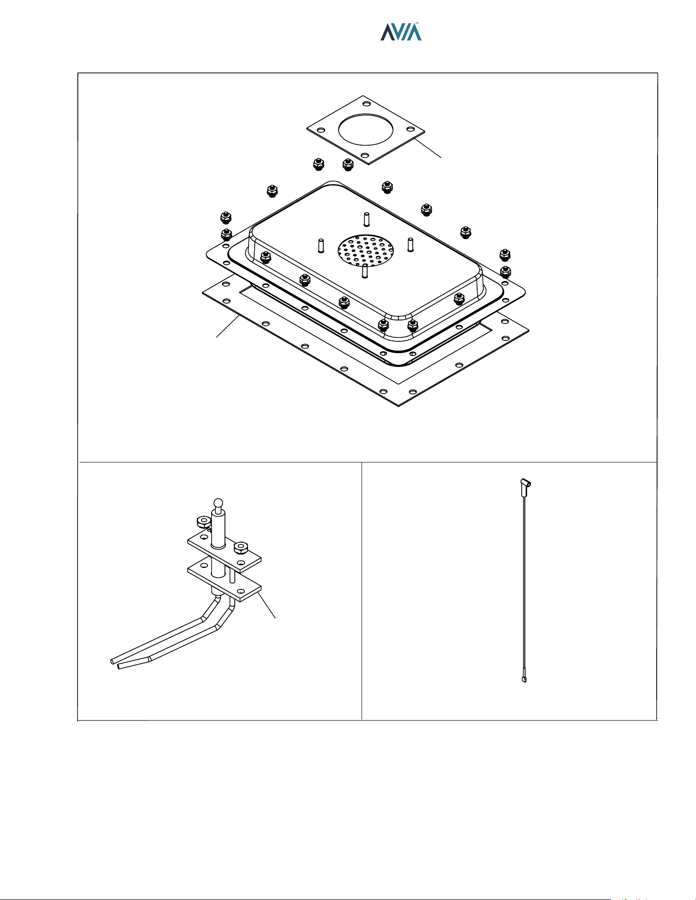
87
INSTALLATION & OPERATION MANUAL
1-B
2-B
2-F
1-P 3-P
2-P
BURNER ASSY.
IGNITER TENSION WIRE
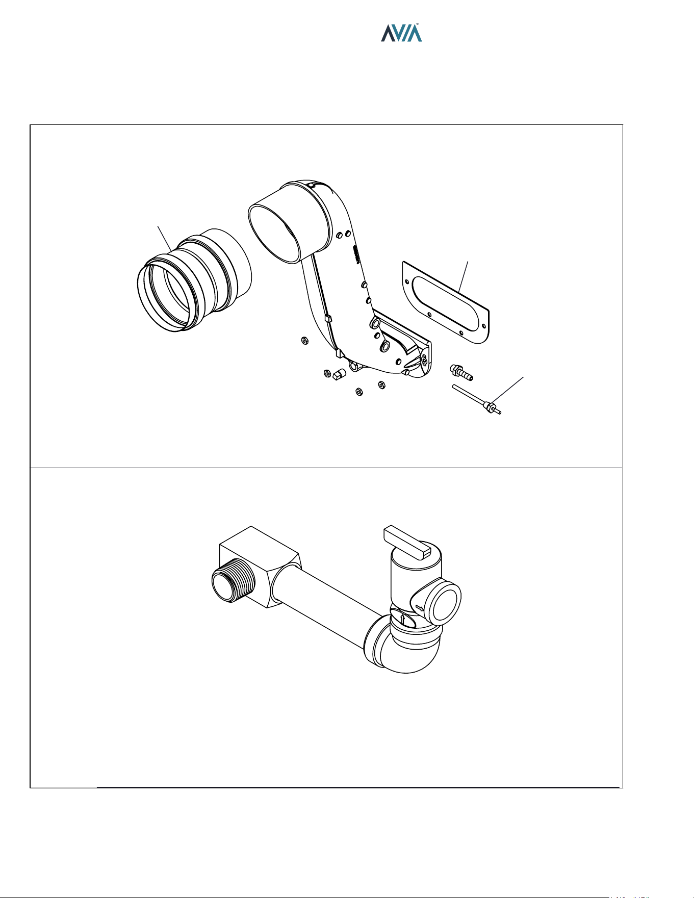
88
INSTALLATION & OPERATION MANUAL
1-V
2-V
3-V
11C
11-M (OPTIONAL)
FLUE EXHAUST, FLUE ADAPTER & VENT SENSOR
PRV LINE
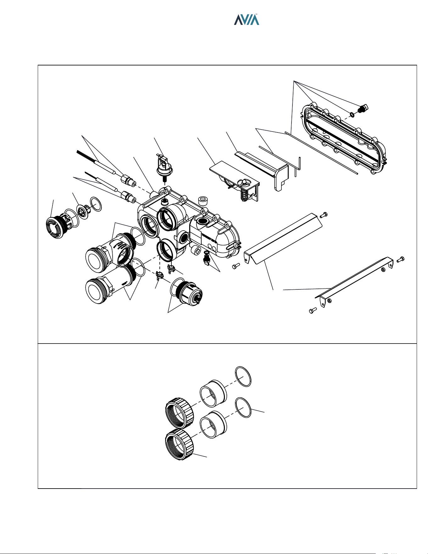
89
INSTALLATION & OPERATION MANUAL
14-H
15-H
4-H
12-M
7-H
9-H
7-C
8-C
12-H
13-H
16-H
11-H
10-H
10-C
9-C
8-H
6-H
5-H
3-H
HEAT EXCHANGER & MISC. COMPONENTS
CPVC CONNECTIONS
90
INSTALLATION & OPERATION MANUAL
CALL
OUT DESCRIPTION 264A 404A
B BURNER
1-B Kit-Burner 018873F 018873F
2-B Kit-Burner Gasket 018878F 018878F
C CONTROLS
1-C Kit-Temp Sensor Limit 018853F 018853F
2-C Kit-Ignition Board 018857F 018933F
3-C Kit-Transformer 120/240/24V 018858F 018858F
4-C Kit-Pressure Vent 018928F 018928F
5-C Kit-Pressure Air 018929F 018929F
6-C Kit-Pressure Differential 018930F 018931F
7-C Kit-Temperature Inlet Sensor 009577F 009577F
8-C Kit-Temperature Outlet Sensor 019043F 019043F
9-C Kit-High Limit 2-HL2-Surface Mount 019044F 019044F
10-C Kit-High Limit 1-HL1-Surface Mount 019045F 019045F
11-C Kit-Temperature Vent Sensor 019046F 019046F
F FAN
1-F Kit-Blower Comb Air 018865F 018961F
2-F Kit-Blower Gasket 018898F 018898F
G GAS VALVE
1-G Blower/Gas Train Assy
Kit-Blower/Gas Train Natural (0-4500 Ft) 018861F 018862F
Kit-Blower/Gas Train Propane (0-4500 Ft) 018863F 018864F
2-G Gas Orifice
Kit-Gas Orifice Natural (0-4500 Ft) 018866F 018867F
Kit-Gas Orifice Propane (0-4500 Ft) 018868F 018869F
3-G Kit-Gas Valve w/ Gas Line Half 018870F 018870F
4-G Kit-Gas Line End 018871F 018871F
5-G Kit-Gas Line Grommet 010778F 010778F
6-G Kit-Adapter Gas Orifice 018926F 018926F
H HEAT EXCHANGER
1-H Kit-Heat Exchanger (Includes Refractory) 018900F 018901F
Kit-Heat Exchanger Plastic Nickel Coated 019383F 019384F
2-H Kit-Tube Bundle (Includes Refractory)* 018849F 018850F
Kit-Tube Bundle Nickel Coated 019387F 019388F
3-H Kit-Heat Exchanger Baffle 019047F 019048F
4-H Kit-Inlet/Outlet Header Complete 019049F 019049F
Kit-Inlet /Outlet Header 019050F 019050F
5-H Kit-Return Header 019051F 019051F
6-H Kit-Header Gasket (2) 019052F 019052F
7-H Kit-Bypass Assy 019054F 019056F
8-H Kit-Drain Plug Pool 006721F 006721F
9-H Kit-Inlet/Outlet Header Dam 019059F 019059F
10-H Kit-Inlet Header Adapter 019060F 019060F
11-H Kit-Outlet Header Adapter 019061F 019061F
12-H Kit-Unitherm Governor 019062F 019062F
13-H Kit-Unitherm Governor Plug Polymer 006720F 006720F
14-H Kit-2" CPVC Connector & Nut (2) 006723F 006723F
15-H Kit-O Ring Inlet/Outlet Pool (2) 006724F 006724F
16-H Kit-ProTek Shield Assy 017960F 017960F
*WARNING: The Hydraulic conditions or water chemistry that caused the tube bundle to fail have very likely also damaged the
bypass valve. We recommend to inspect the bypass assembly. Failure to do so could cause premature failure of this replacement
part.
91
INSTALLATION & OPERATION MANUAL
M MISCELLANEOUS COMPONENTS 264A 404A
1-M Kit-Top Cover Assy 018852F 018852F
4-M Kit-Top Lid 018902F 018902F
5-M Kit-Rocker Switch SPST 009493F 009493F
6-M Kit-Display Assembly 018904F 018904F
7-M Kit-Top Clip Assy 018905F 018905F
8-M Kit-Top Knurled Screw Assy 018906F 018906F
10-M Kit-Display Gasket 018921F 018921F
2-M Kit-Power Cable Grommet 018884F 018884F
3-M Kit-Corner Post 018891F 018891F
9-M Kit-PRV Grommet 018920F 018920F
11-M Kit-PRV Line 018936F 018936F
12-M Kit-Pressure Switch 1.75 PSI 006737F 006737F
22-M Kit-Pressure Switch 11 PSI Special-See Water Pressure Switch Adj. (Not Shown) 009133F 009133F
13-M Kit-Wire Bonding 14/6 Connector 007155F 007155F
14-M Kit-Tube Air Sample (Blower/Vent/Air Pressure Switch) 010348F 010348F
15-M Kit-Wire/Harness (Not Shown) 019064F 019064F
16-M Touch-up Paint (Not Shown)
Cool Dark Gray 750256 750256
Warm Dark Gray 750258 750258
Maroon 750265 750265
17-M Kit-Deliming (Not Shown) 052871F 052871F
18-M RTV Sealant 2.8 oz (Not Shown) 008924F 008924F
19-M RTV Sealant 10 oz (Not Shown) 005755F 005755F
20-M Kit-Elevation Propane (Not Shown) 018762F 018762F
92
INSTALLATION & OPERATION MANUAL
CALL
OUT DESCRIPTION 264A 404A
P PILOT
1-P Kit-Igniter Direct Spark 018874F 018874F
2-P Kit-Igniter Gasket 018879F 018879F
3-P Kit-Hi Tension Wire 018875F 018875F
R REFRACTORY
1-R Kit-Refractory Assy 018848F 018848F
S SHEET METAL / CABINET
1-S Kit-Top Right Panel Assy
Raypak/Rheem/Ruud (Cool Dark Gray) 018851F 018851F
Jacuzzi (Beige) 018973F 018973F
2-S Kit-Cabinet Top Support 018854F 018854F
3-S Kit-Transformer Cover 018855F 018855F
4-S Kit-Ignition Board Cover 018856F 018856F
5-S Kit-Ignition Board Mounting 018859F 018859F
6-S Kit-Anti Rotation Gas Valve Bracket 018860F 018860F
7-S Kit-Comb Chamber Seal 018872F 018872F
8-S Kit-Junction Box 018876F 018876F
9-S Kit-Vent Cover Assy 018881F 018881F
10-S Kit-Vent Mounting Panel
Raypak/Rheem/Ruud (Cool Dark Gray) 018882F 018882F
Jacuzzi (Beige) 018977F 018977F
11-S Kit-Panel Left Side Vent
Raypak/Rheem/Ruud (Cool Dark Gray) 018883F 018883F
Jacuzzi (Beige) 018976F 018976F
12-S Kit-Panel Junction Box Cover
Raypak/Rheem/Ruud (Cool Dark Gray) 018885F 018885F
Jacuzzi (Beige) 018975F 018975F
13-S Kit-Panel Front
Raypak (Maroon) 018888F 018888F
Rheem (Warm Dark Gray) 018889F 018889F
Ruud (Cool Dark Gray) 018887F 018887F
Jacuzzi (Beige) 018890F 018890F
14-S Kit-Panel Rear
Raypak (Maroon) 018893F 018893F
Rheem/Ruud (Cool Dark Gray) 018894F 018894F
Jacuzzi (Beige) 018895F 018895F
15-S Kit-Base Assy 018892F 018892F
16-S Kit-Bottom Right Panel UG
Raypak/Rheem/Ruud (Cool Dark Gray) 018896F 018896F
Jacuzzi (Beige) 018978F 018978F
17-S Kit-Bottom Right Panel PRV
Raypak/Rheem/Ruud (Cool Dark Gray) 018897F 018897F
Jacuzzi (Beige) 018974F 018974F
18-S Kit-Comb Chamber Support 018899F 018899F
V VENTING
1-V Kit-Flue Exhaust 018877F 018877F
2-V Kit-Flue Exhaust Gasket 018880F 018880F
3-V Kit-Flue Adapter 4" SS 018932F 018932F
CONVERSION KITS*
Pro. to Nat. 018866F 018867F
Nat. to Pro. 018868F 018869F
* Gas conversions are to be done only by a qualified agency.
If you need information for an older model heater, go to the Raypak website’s model number history: https://www.raypak.
com/technical-resources/documents/ link; or contact your Raypak representative for assistance.
Find a Raypak representative for Commercial or Pool product: https://www.raypak.com/commercial-sales-rep/ or https://
www.raypak.com/pool-heater-sales-rep/.

93
INSTALLATION & OPERATION MANUAL
2. Product Approved side wall horizontally-vented gas-fueled
equipment installed in a room or structure separate from
the dwelling, building or structure used in whole or in part for
residential purposes.
(c) MANUFACTURER REQUIREMENTS - GAS EQUIPMENT
VENTING SYSTEM PROVIDED. When the manufacturer of
Product Approved side wall horizontally-vented gas equipment
provides a venting system design or venting system components
with the equipment, the instructions provided by the manufacturer
for installation of the equipment and the venting system shall
include:
1. Detailed instructions for the installation of the venting system
design or the venting system components; and
2. A complete parts list for the venting system design or venting
system.
(d) MANUFACTURER REQUIREMENTS - GAS EQUIPMENT
VENTING SYSTEM NOT PROVIDED. When the manufacturer
of a Product Approved side wall horizontally-vented gas-fueled
equipment does not provide the parts for venting the flue
gases, but identifies “special venting systems”, the following
requirements shall be satisfied by the manufacturer:
1. The referenced “special venting system” instructions shall be
included with the appliance or equipment installation instructions;
and
2. The “special venting systems” shall be Product Approved by
the Board, and the instructions for that system shall include a
parts list and detailed installation instructions.
(e) A copy of all installation instructions for all Product Approved
side wall horizontally-vented gas-fueled equipment, all venting
instructions, all parts lists for venting instructions, and/or all
venting design instructions shall remain with the appliance or
equipment at the completion of the installation.
GAS PRESSURE SUPERVISION
The Commonwealth of Massachusetts requires listed high
and low gas pressure switches (manual-reset) for any model
with a maximum firing input greater than 1,000,000 Btu/Hr in
accordance with 248 CMR 7.04(11)(d).
A gas pressure regulator (field-supplied) is required in the gas
train ahead of the heater, for heaters having input rates greater
than 1,000,000 Btu/Hr, in accordance with 248 CMR 7.04 Figure
3B requirements.
The Commonwealth of Massachusetts requires compliance with
regulation 248 CMR 4.00 and 5.00 for installation of through – the
– wall vented gas appliances as follows:
(a) For all side wall horizontally-vented gas-fueled equipment
installed in every dwelling, building or structure used in whole
or in part for residential purposes, including those owned or
operated by the Commonwealth and where the side wall exhaust
vent termination is less than seven (7) feet above finished grade
in the area of the venting, including but not limited to decks and
porches, the following requirements shall be satisfied:
1. INSTALLATION OF CARBON MONOXIDE DETECTORS. At
the time of installation of the side wall horizontally-vented gas-
fueled equipment, the installing plumber or gasfitter shall observe
that a hard wired carbon monoxide detector with an alarm and
battery back-up is installed on the floor level where the gas
equipment is to be installed. In addition, the installing plumber
or gasfitter shall observe that a battery operated or hard wired
carbon monoxide detector with an alarm is installed on each
additional level of the dwelling, building or structure served by
the side wall horizontal vented gas-fueled equipment. It shall be
the responsibility of the property owner to secure the services of
qualified licensed professionals for the installation of hard wired
carbon monoxide detectors
a. In the event that the side wall horizontally-vented gas-fueled
equipment is installed in a crawl space or an attic, the hard wired
carbon monoxide detector with alarm and battery back-up may
be installed on the next adjacent floor level.
b. In the event that the requirements of this subdivision can
not be met at the time of completion of installation, the owner
shall have a period of thirty (30) days to comply with the above
requirements; provided, however, that during said thirty (30) day
period, a battery operated carbon monoxide detector with an
alarm shall be installed.
2. APPROVED CARBON MONOXIDE DETECTORS. Each
carbon monoxide detector as required in accordance with the
above provisions shall comply with NFPA 720 and be ANSI/UL
2034 listed and IAS certified.
3. SIGNAGE. A metal or plastic identification plate shall be
permanently mounted to the exterior of the building at a
minimum height of eight (8) feet above grade directly in line with
the exhaust vent terminal for the horizontally-vented gas-fueled
heating appliance or equipment. The sign shall read, in print size
no less than one-half (1/2) inch in size, “GAS VENT DIRECTLY
BELOW. KEEP CLEAR OF ALL OBSTRUCTIONS”.
4. INSPECTION. The state or local gas inspector of the side
wall horizontally-vented gas-fueled equipment shall not approve
the installation unless, upon inspection, the inspector observes
carbon monoxide detectors and signage installed in accordance
with the provisions of 248 CMR 5.08(2)(a)1 through 4.
(b) EXEMPTIONS: The following equipment is exempt from 248
CMR 5.08(2)(a)1 through 4:
1. The equipment listed in Chapter 10 entitled “Equipment Not
Required To Be Vented” in the most current edition of NFPA 54
as adopted by the Board; and
16. IMPORTANT INSTRUCTIONS FOR THE
COMMONWEALTH OF MASSACHUSETTS
94
INSTALLATION & OPERATION MANUAL
17. QR CODES
View this Installation Manual on your smart device.
The QR Codes will take you to the most current version of this manual. Previous
versions of manuals can be found in the document library at Raypak.com.
P/N: 100-10000111 AVIA Operation Instructions AVIA Troubleshooting
P/N: 241945 Raymote Quick Start Guide Raymote App
P/N: 242049 Protégé Quick Start Guide Raymote Automation & Scheduling

95
INSTALLATION & OPERATION MANUAL
Notes
Raypak, Inc., 2151 Eastman Avenue, Oxnard, CA 93030 (805) 278-5300
Litho in U.S.A.