JiuYuan Environmental Technology
(Zhongshan) Co., LTD
Smart Planting Controller
JYC-M3 Series User Manual

Catalogue
1. Product Overview
2. Product Appearance and Interface
3. Power On and Connection
4. Main interface features
5. Function Settings
6. Alert function
7. APP download and usage
8. Notes
9. Packing list
9. Local certification and hazard information
11. Technical support

1. Product Overview
This intelligent planting system controller is a smart control device specially designed for
indoor planting, with the following functions:
✅
Real-time temperature and humidity monitoring (requires connection to
temperature and humidity sensor)
✅
Real-time CO2 concentration monitoring (requires CO2 sensor connection)
✅
VPD (Vapor Pressure Deficit) Smart Adjustment
✅
Light intensity adjustment
✅
Fan speed
✅
damping control
✅
heating control
✅
Dual-mode Wi-Fi and Bluetooth
✅
Remote Management via App (Android)
✅
Supports planting growth stage settings
✅
Supports weekly plans and scheduled tasks
✅
Supports multilingual interface
✅
Supports custom control devices via the TYPE-C interface
✅
Supports controller series expansion. The first controller is set as the master by
default, while other devices are set as slaves by default. Slaves will synchronize and copy all
parameters from the master.
✅
Supports Bluetooth connectivity with peripheral devices, enabling integration with more
farming-related equipment.
✅
Supports Wi-Fi connectivity for internet access, enabling remote management via mobile
app to automate crop cultivation environment control.
✅
Supports power-off memory function. The power-off memory lasts about 24 hours. If it
exceeds 24 hours, the device will restore the factory default value.
2. Product Appearance and Interface
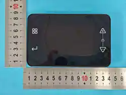
Power supply: 12V/1A DC power (via Type-C interface)
-Screen: 3.5-inch TFT display
-Keys: 4 touch buttons (Settings, Confirm, +, -)
- joggle
:
-5 TYPE-C ports (for devices like lights, fans, heaters, humidifiers, and CO
₂
)
-1 x 2.5mm DC port (for temperature and humidity sensor)
Water resistance: IP65
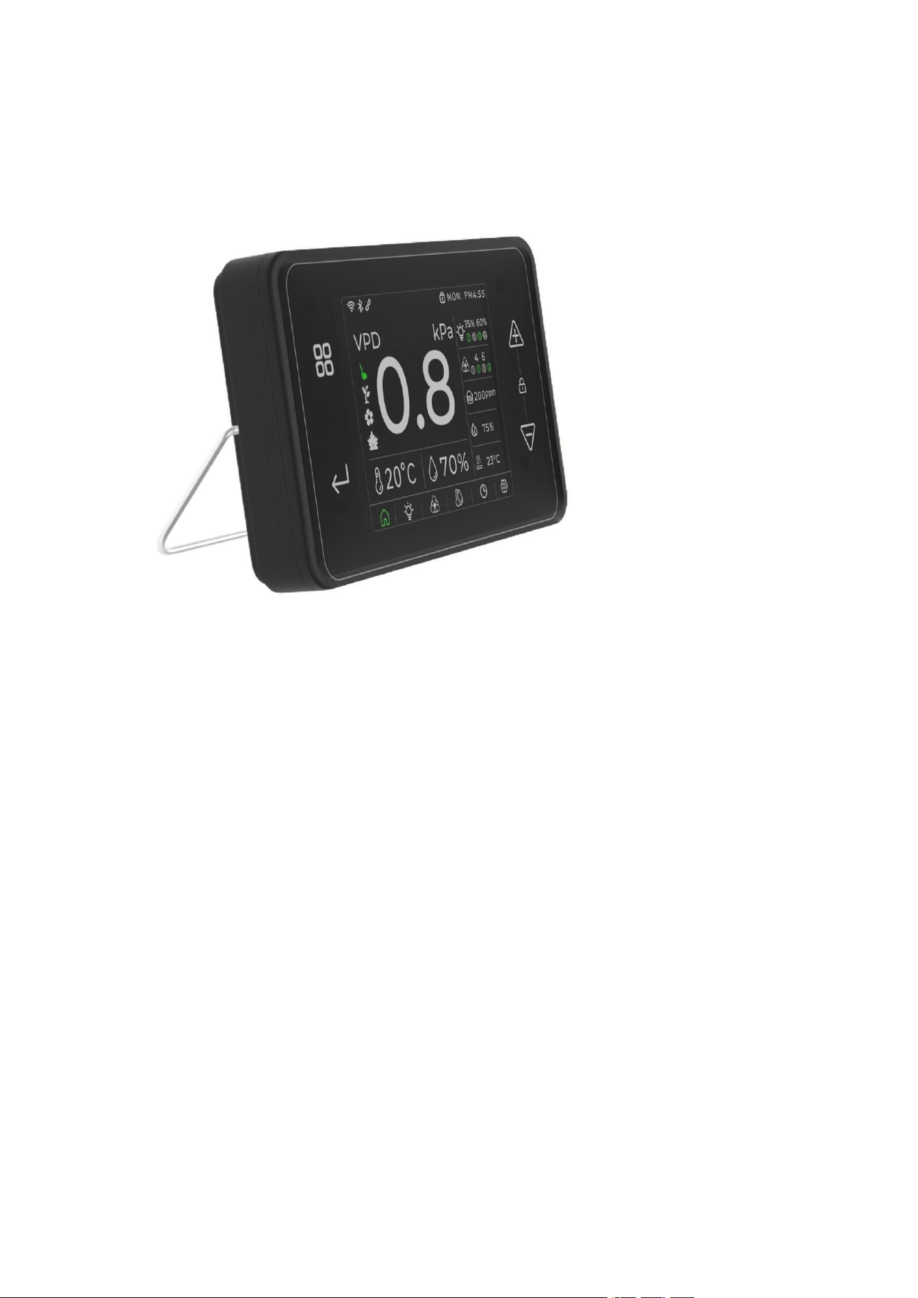
Installation method: The back of the body is equipped with a metal hook (support), which can be
placed on the table; it can be hung on the wall or outside the planting tent.
3. Power On and Connection
⑴
.Connect any TYPE-C port to a 12V power supply
→
Turn on the power
→
The screen
displays the brand logo and a welcome message
⑵
.Wait for startup
→
Enter the main interface
⑶
.Network connection
→
Wi-Fi/BLE icon in the top-left corner shows the connection status
⑷
.Pair the APP
→
Scan the QR code on the product's instruction manual or packaging
→
Download the APP and follow the prompts to add the device.
⑸
.Basic Settings:
a.Connect the Type-C cable to the product's ports 1-5. Then connect the other end of the
cable to devices such as a grow light, fan, CO
₂
sensor, humidifier, or heater. Finally,
configure the interface in the controller's settings interface.
b.Set the lighting, VPD, temperature and humidity, and timer in the
④
area of the following
figure. The device will automatically start after saving.
4. Main interface features
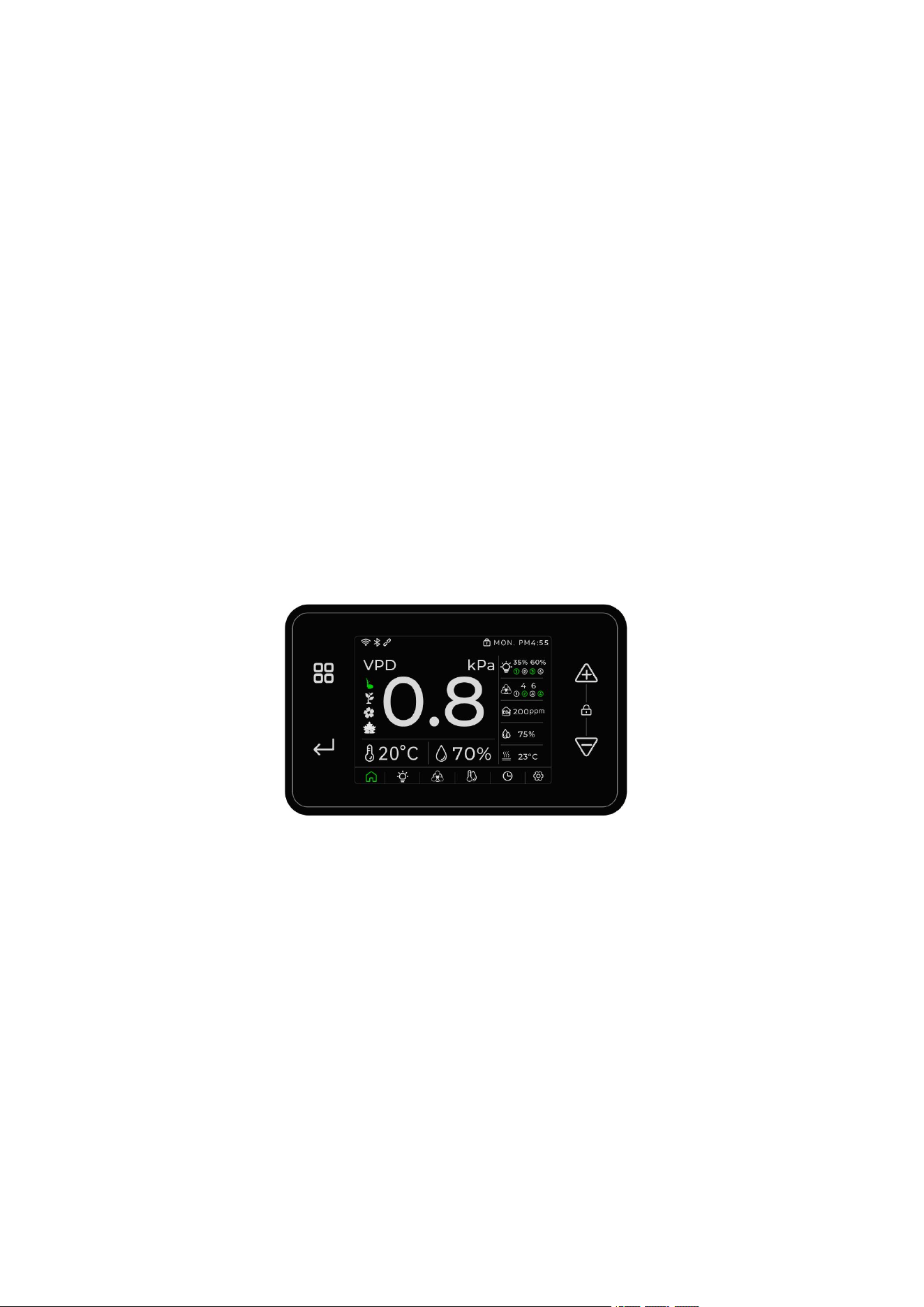
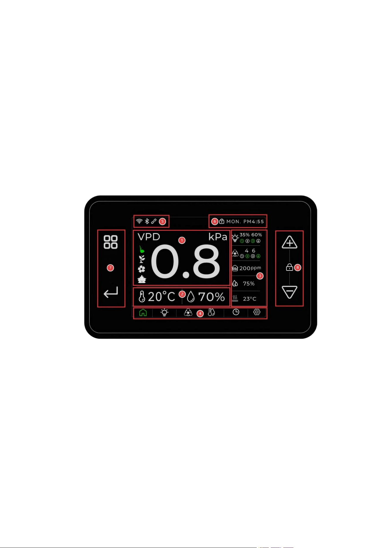
Home screen illustration
The home screen is divided into five areas:
⑴
.Region 1: Displays real-time VPD data status and specified growth stages (germination, growth,
flowering, and maturity)
⑵
.Region 2: Displays real-time temperature data (switchable between
°
C/
℉
) and humidity data
(%);
⑶.
Zone 3: Displays the number of connected lights and their brightness levels; shows the number
of connected fans and their wind speeds; displays real-time readings from connected CO2 sensors;
indicates the real-time status of connected humidifiers (on/off); shows the real-time status of
connected heaters (on/off);
⑷ .
Region 4: Functional Page Navigation: Home, Lighting Settings, Fan Settings, VPD and
Temperature/Humidity Settings, Weekly Schedule and Timer Settings, Controller Basic Settings
(Home, Lights, Fans, H/T, Time, SET)
⑸.
Region 5: Controller connection status (WIFI, Bluetooth, local expansion connection)
⑹.
Region 6: Display lock screen status and local time
⑺.
Region 7: Menu selection button and confirm button (Save and execute)
⑻.
Region 8: Data setting buttons (+ for increase, -for decrease). Press both buttons for over 5
seconds to lock the device. Press both buttons again for over 5 seconds to unlock.
The device has been inactive for over one minute and enters silent mode: the screen locks and all
lights and screens turn off. In this state, touching any button will exit silent mode and activate the
device.
5. Function Settings
⑴.
Light Control (Lights)
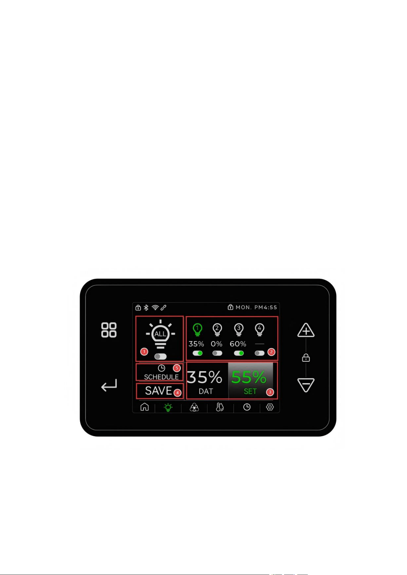
Growing Light Setup Diagram
This product supports PWM regulation technology, with gear settings ranging from OFF to 100%
in 10 steps.
This device supports up to 5 growth light control channels per unit.
This product supports serial expansion with multiple controllers. When multiple units' COM5
ports are connected in series via TYPE-C, it can only configure 4 control terminal devices.
This product supports up to 5 independent control channels for grow lights, as well as centralized
control for all connected grow lights.
1. Area 1: Unified control option for grow lights. When the button below ALL is activated (turns
green), Area
②
becomes gray and cannot be adjusted, while the parameters set in Area
③
are
displayed uniformly.
2. Zone 2: Independent control option for grow lights. In this interface, users can select and
confirm the activation of lights 1-5 using the menu keys. After setting the parameters for the
corresponding light in Zone
③
, the icon will turn green. The controller will then manage the light
according to these preset parameters. When the controller is expanded in series, this operation can
only control up to 4 grow lights.
3. Zone 3: Displays real-time brightness values and set points of connected and selected grow
lights. Users can adjust brightness parameters using the +/-buttons in the right adjustment panel.
Each click moves the brightness level by 10% increments. After completing data input, select the
"SAVE" option in the
④
area via the menu button, then confirm by pressing the OK button for 3
seconds. The corresponding light icon will turn green, and the controller will operate the light
according to the saved settings.
4. Region 5: To manage scheduling and time settings for the selected grow light, select this region
via the menu button, press OK, and you'll be redirected to the scheduling page to continue
configuration.
⑵.
Fan Control (Fans)
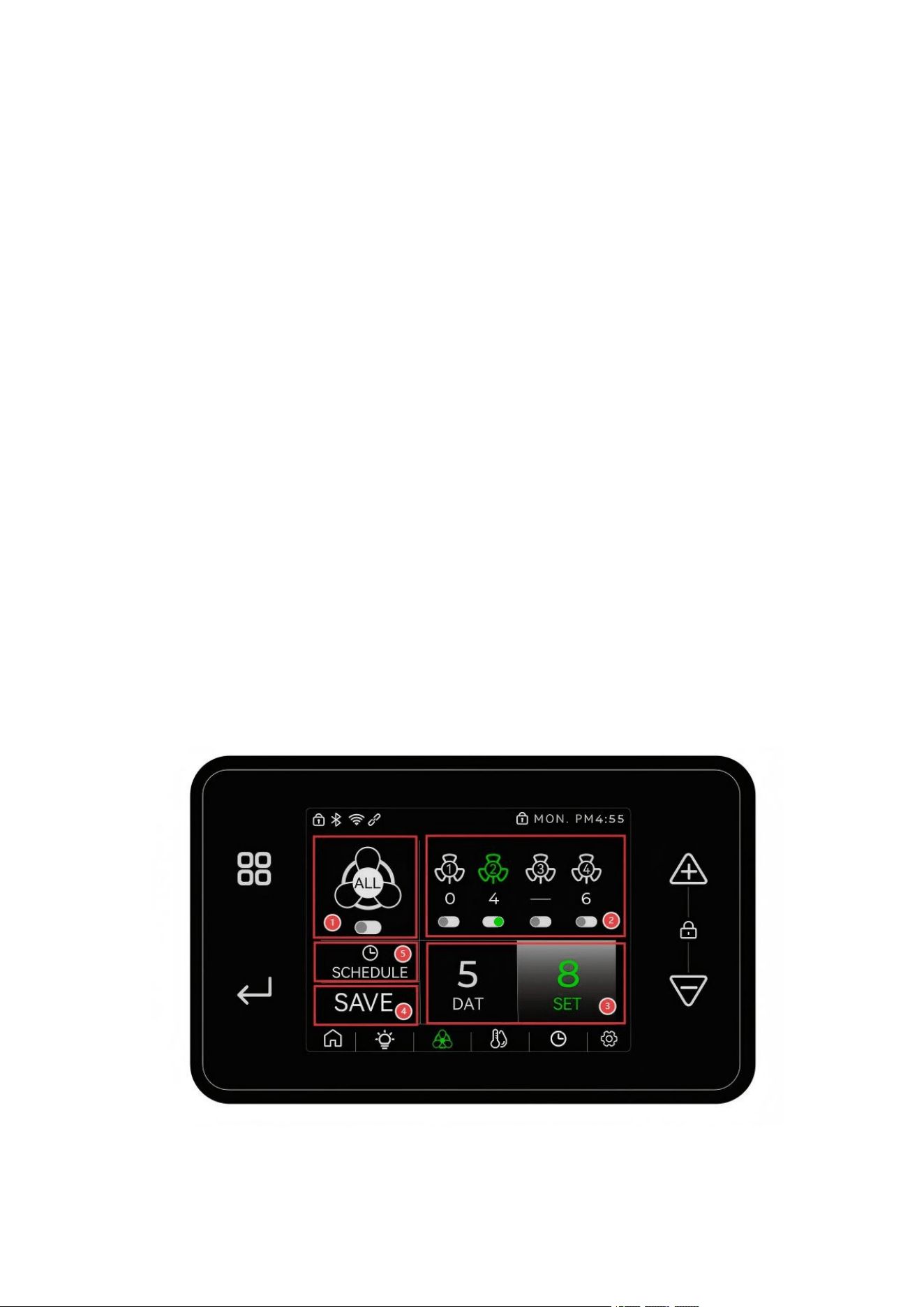
Fan layout diagram
This product supports PWM regulation technology, with gear settings ranging from 0 to 9, F (Full
Speed), and 10th gear.

This device supports up to 5 fan control channels per unit.
This product supports serial expansion with multiple controllers. When multiple units' COM5
ports are connected in series via TYPE-C, it can only configure up to 4 control terminal devices.
This product supports up to 5 independent fan controls, as well as centralized control of all
connected fans.
1. Area 1: Unified control option for fans. When the button below ALL is turned on (changes to
green), Area
②
turns gray and becomes non-adjustable, while the parameters set in Area
③
are
displayed uniformly.
2. Zone 2: Independent Fan Control Option. In this interface, users can select the confirmation
button for lamps numbered 1-5 using the menu keys. After setting the parameters for the
corresponding lamp in Zone
③
and saving the configuration, the lamp icon will turn green. The
controller will then manage the fan according to these preset parameters. When the controller is
expanded in series, this operation can only control up to 4 fans.
3. Zone 3: Displays real-time wind speed and set values for connected and selected fans. Users can
adjust fan brightness parameters using the +/-buttons in the right adjustment panel. Each click
selects a speed level (1-F). After completing data input, select the SAVE option in the
④
area via
the menu button, then press the OK button for 3 seconds to confirm. The corresponding fan icon
will turn green, and the controller will operate the fan according to the saved parameters.
4. Region 5: To manage scheduling and time settings for the selected fan, select this region via the
menu button, press OK, and proceed to the scheduling and timing page to continue configuration.
⑶.
VPD and Temperature/Humidity Settings (VPD + H/T)
VPD setup diagram
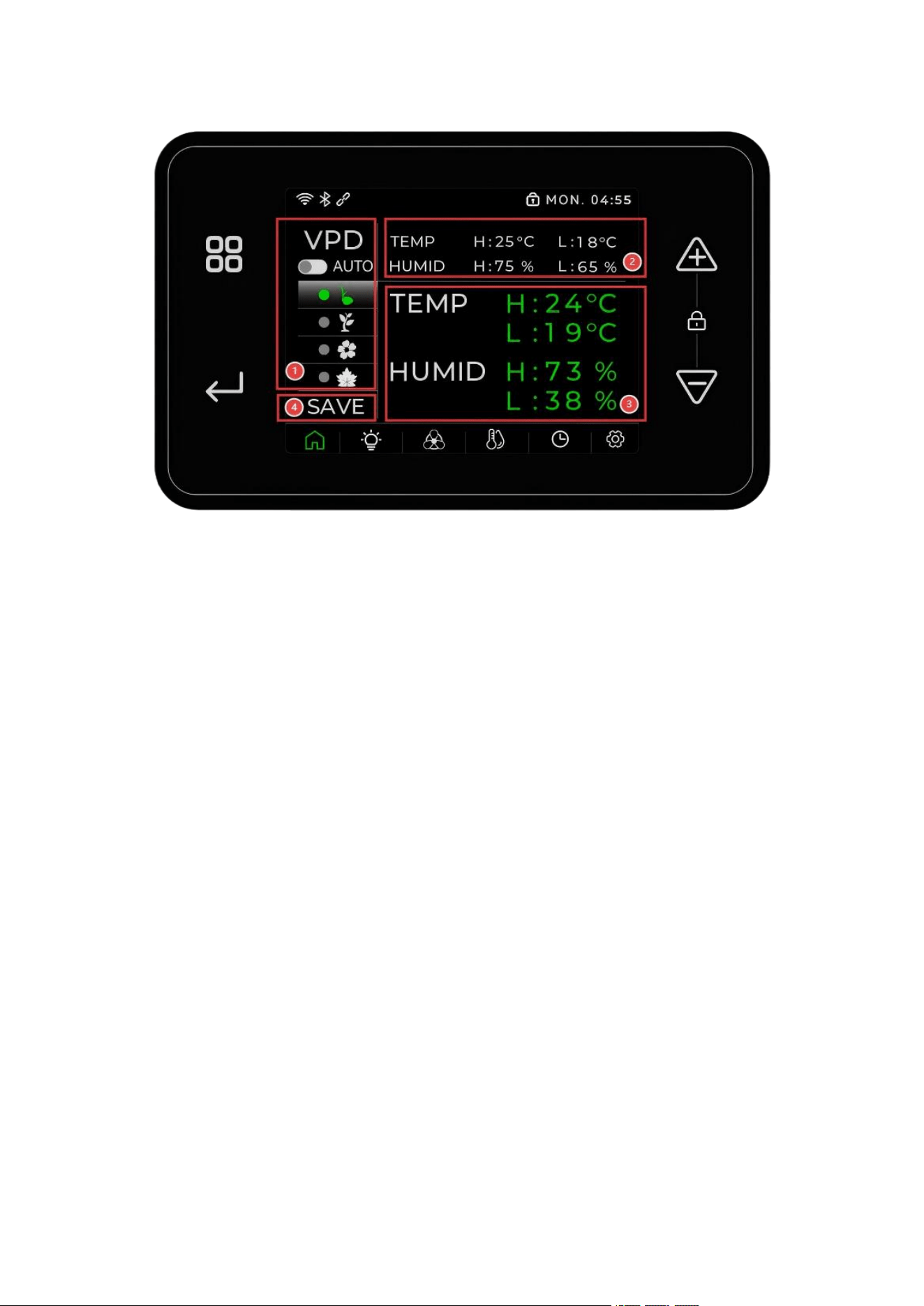
This product includes preset VPD parameters for plant growth. After connecting to the internet,
you can download and use more VPD parameters for various plant types (continuously improving
and upgrading).
-The product's VPD can be precisely controlled according to plant growth stages: germination,
early flowering, peak flowering, and maturity.
-This product displays real-time temperature and humidity data (unconnected sensors are gray)
This product features a DIY mode, allowing users to set their own upper (HIGH TEMP) and lower
(LOW TEMP) temperature limits.
This product features a DIY mode, allowing users to set their own upper (HIGH HUMID) and
lower (LOW HUMID) humidity limits.
a. Area 1: The automatic control selection zone for VPD. When the button below VPD turns
green, Area
③
becomes gray and unadjustable. After activating VPD's automatic mode, users
can select plant growth stages in this area to enable intelligent management control based on the
plant's developmental phase.
b. Region 2: Real-time temperature and humidity parameter display area;
c. Zone 3: User-Defined VPD Parameters Setting Area. Users can adjust temperature and
humidity parameters using the +/-buttons in this zone, with each click modifying the setting by
1
°
C/F. In the VPD Automatic Control Selection Area, even when the VPD AUTO option is not
selected, users can still customize temperature and humidity parameters for specific plant
growth stages. After completing data input, select the SAVE option in the
④
area using the
menu buttons, then confirm by pressing the OK button for 3 seconds. The controller will then
manage and control peripheral devices according to these customized parameters.

⑷.
Schedule and Time
Schedule and timer settings diagram
This product supports weekly scheduling and timer settings for five devices: grow lights, fans, CO
₂
sensors, humidifiers, and heaters.
This product supports weekly plan setting (Monday to Sunday cycle)
Supports daily scheduling (24-hour system), offering two fixed AM time slots and two fixed PM
time slots for scheduling.
a. Area 1: The time-scheduled device selection area. Users can select a device using the menu
keys to set weekly plans and daily schedules, or choose devices individually to configure their
weekly plans and daily schedules.
b. Area 2: The selection area for weekly planning. When users select a time device, they can set
daily schedules from Monday to Sunday in this area to create weekly plans.
c. Zone 3: Time Setting Area. Users can adjust timing parameters using the +/-buttons in this
zone, with each click modifying the setting by 0.5 hours. The device offers 24-hour daily
scheduling with two fixed AM and two fixed PM time slots. Press the OK button for 3 seconds to
confirm the settings, after which the controller will manage and control peripheral devices
according to these parameters.
⑸.
System Settings (SET)
Basic Settings Diagram
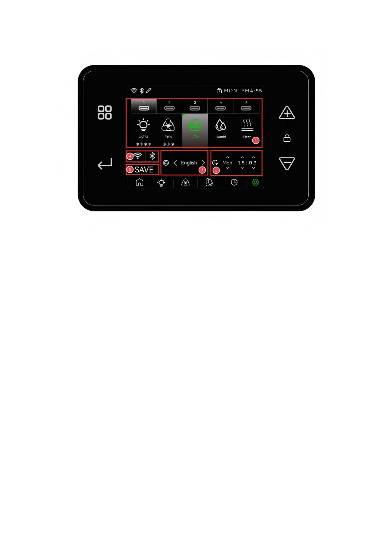
This product supports customizable TYPE-C interface configurations, allowing users to assign 1-5
TYPE-C ports to physical connections for devices such as grow lights, fans, heaters, humidifiers,
and CO
₂
sensors.
This product offers language options: English, Spanish, French, German, Italian, Portuguese.
-This product provides local time setting; when connected to the Internet, the device will
automatically check the network time;
This product provides temperature unit settings and allows switching between
℃
and
℉
display
units.
a. Area 1: The TYPE-C interface selection zone. Users can select any TYPE-C interface via the
menu buttons. By using the menu and confirm buttons, they can define the selected interface in the
diagrammed device. The user may configure all five TYPE-C interfaces as a single device or
assign them to different devices individually.
b. Region 2: Set the local time zone. Users can set the local time in this region when using the
device for the first time.
c. Region 3: Language settings area. Users can adjust the local display language using the
+/-buttons in this area.
d. Zone 4: Wi-Fi/BLE Connection Status Indicator. When the Wi-Fi/BLE icon in this zone
appears green, it indicates the device is currently connected to or has previously connected to a
Wi-Fi/BLE device. A white or gray icon with flashing indicates no active connection. Users can
clear connection data and reset the Wi-Fi/BLE status to factory defaults by selecting the icon in
the zone and holding the confirmation button for over 10 seconds. After 10 seconds of holding, the
icon will flash briefly before returning to white or gray.
6. Alarm function

The controller will issue an alarm when the environmental parameters exceed the set range.
-Temperature too high or too low
-Humidity too high or too low
-VPD too high or too low
-CO
₂
concentration is too high or too low
The alarm will be displayed on the home screen with a red 2-second flash. If the alarm is not
removed within 24 hours, the screen will no longer flash and a red line will be displayed at the
bottom of the display interface to remind the user until the alarm is removed.
7、
Download and use the app
The product manual and packaging box should feature printed or attached QR codes for APP
download.
-Scan this QR code to download and install the app as instructed;
To use the APP to connect devices, you must first register and bind the device.
APP download QR code
8. PRECAUTIONS
Although the product has an IP65 waterproof rating, avoid prolonged exposure to direct water
spray or high temperatures.
Do not leave the controller in direct water spray or high-temperature environments for long
periods.
-Before use, ensure all interfaces are securely connected
-It is recommended to calibrate temperature and humidity sensors and carbon dioxide sensors
regularly; it is recommended to replace temperature and humidity sensors and carbon dioxide
sensors every two years
Sensors and other accessories not certified by the company may damage the device or cause the
implantation to fail. The company shall not be liable for any consequences resulting from such
damage or failure.
If the device does not work properly, restart it or restore factory settings
9. Packing List
⑴.
One host
⑵
. One copy of the instruction manual
⑶
. 4P 2.5m Dual-Head Type-C Cable

⑷.
One temperature and humidity sensor
⑸.
Type-C to RJ12 (6-pin) adapter cable for grow lights (not standard)
10. Machine certification and Statement
1
、
This device is certified with CE, FCC, and ROSH.
2
、
Mobile Device
FCC STATEMENT
1. This device complies with Part 15 of the FCC Rules. Operation is subject to the following two
conditions:(1) This device may not cause harmful interference, and(2) This device must accept
any interference received, including interference that may cause undesired operation.
2. Changes or modifications not expressly approved by the party responsible for compliance could
void the user'sauthority to operate the equipment.
NOTE:
This equipment has been tested and found to comply with the limits for a Class B digital device,
pursuant to Part15 of the FCC Rules. These limits are designed to provide reasonable protection
against harmful interference in aresidential installationThis equipment generates uses and can
radiate radio frequency energy and, if not installed and used in accordance withthe instruictions,
may cause harmful interference to radio communications. However, there is no guarantee
thatinterference will not occur in a particular installation. If this equipment does cause harmful
interference to radio ortelevision reception, which can be determined by turning the equipment off
and on, the user is encouraged to try tocorrect the interference by one or more of the following
measures:
①
Reorient or relocate the receiving antenna.
②
Increase the separation between the equipment and receiver.
③
Connect the equipment into an outlet on a circuit different from that to which the receiver is
connected.
④
Consult the dealer or an experienced radio/TV technician for help
FCC Radiation Exposure Statement
This equipment complies with FCC radiation exposure limits set forth for an uncontrolled
environment. This equipmentshould be installed and operated with minimum distance 20cm
between the radiator & your body
11. Technical Support

For any questions, please contact:
Jiu Yuan Environmental Technology (Zhongshan) Co., LTD
Official website: HTTPs//black-tents.com
Customer service contact:
Any changes to this manual will not be notified separately. Please refer to the actual product functions
and interface.
Version: V1.0
Updated: October 2025