

Nilfisk A/S Nilfisk Confidential Proprietar
FCC ID:
y
06.05.2026/
DongGuan Page
1
of
16
China
NEO P36 Hardware Specification and Manual
References
NEO_Platform36 REV_D Schematic.
Revision Information
Created: Revision Name Comments
2026/4/13 0.1 Seven Liu Initial revision
Modified
2AVNE-P36

Nilfisk A/S Nilfisk Confidential Proprietary
06.05.2026/
DongGuan Page
2
of
16
China
Table of Contents
1 Introduction.................................................................................................3
2 System description .................................................................................... 3
2.1 Embedded functions and peripherals ......................................................................4
2.1.1 Leakage current during power off ................................................................... 4
2.1.2 Local power rails .............................................................................................4
2.1.2.1 3.3 Volt ..................................................................................................... 4
2.1.2.2 5 Volt ........................................................................................................ 4
2.1.2.3 12 Volt ...................................................................................................... 4
2.1.3 EEPROM ........................................................................................................ 4
2.2 Output functions ...................................................................................................... 5
2.2.1 AUX Low side switch output. .......................................................................... 5
2.2.2 Half bridge output ........................................................................................... 5
2.2.3 H bridge output ............................................................................................... 5
2.2.4 1x24V output ...................................................................................................6
2.2.5 UI output ......................................................................................................... 6
2.2.6 1x PWM output .............................................................................................. 6
2.3 Input functions ......................................................................................................... 7
2.3.1 On/OFF input .................................................................................................. 7
2.3.2 Switch input .................................................................................................... 7
2.3.3 Digital input ..................................................................................................... 7
2.4 Communication functions ........................................................................................ 8
2.4.1 CAN ................................................................................................................ 8
2.4.2 Programming interface ................................................................................... 8
2.4.3 Debug interface .............................................................................................. 8
2.4.4 Bluetooth interface ..........................................................................................9
2.5 Other features ....................................................................................................... 10
2.5.1 Bulk cap current pre-charge ..........................................................................10
2.5.2 Voltage rail monitoring .................................................................................. 10
2.5.3 Voltage reference ......................................................................................... 10
2.5.4 Soft start ....................................................................................................... 10
2.5.5 Current sense circuit .....................................................................................10
2.5.6 Peak overcurrent (short circuit) protection .................................................... 10
2.5.7 Reverse polarity protection ........................................................................... 11
2.5.8 Charger Input detect ..................................................................................... 11
2.6 P36 PCBA Connector ............................................................................................12
3 General Specifications ............................................................................ 14
3.1 Dimenion ............................................................................................................... 14
3.2 Others ................................................................................................................... 15
Nilfisk A/S Nilfisk Confidential Proprietary
06.05.2026/
DongGuan Page
3
of
16
China
1 Introduction
This document specifies the hardware specifications for the P36.
2 System description
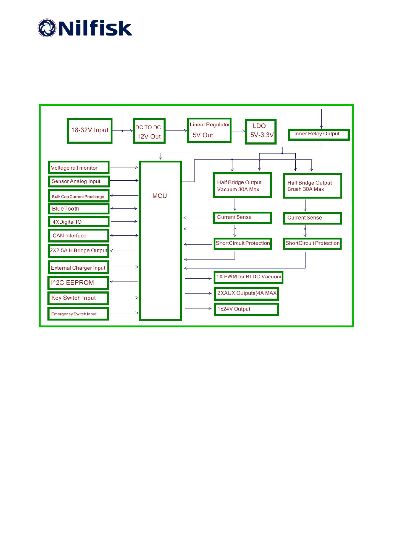
The P36 consists of the following functional blocks, and the block diagram shown as below:
2 x 2.5A H Bridget output
4 x Digital I/O
2 x Aux output 4A(max)
2 x DC Motor/pump output 30A (max) with current sense
1 x Power key switch for user button input
1 x 24V output for Traction controller KSI signal.
1 x PWM signal for BLDC Vacuum.
1 x Detergent sensor input.
Battery voltage measurement.
Battery communication interface(COMBAT-2) and Lead-acide battery interface.
32 Bit Microprocessor
Power supplies: 5Vdc, 12Vdc, and 3.3Vdc
1K Bytes EEPROM
Bulk cap current pre-charge function.
TC-1 Interface (CAN)
Programming interface(ST SWD)
R&D Interface(USART). Test point output mode.
Bluetooth transceiver

Nilfisk A/S Nilfisk Confidential Proprietary
06.05.2026/
DongGuan Page
4
of
16
China
2.1 Embedded functions and peripherals
2.1.1 Leakage current during power off
To satisfy the biggest possible battery configurations, a low leakage input current is mandatory.The
aim is to get below 500uA with 30V on across the main power input terminals. This demand
necessitates the use of a pass transistor that can effectively block power to the embedded DC/DC
converters.
2.1.2 Local power rails
The P36 is powered by a Nilfisk Combat 2 battery pack or Lead-acid battery stack.
The nominal operating input voltage range is 20 – 30Vdc. Maximum input is 32Vdc.
The local power supplies will provide 3.3V for MCU and other logic functions, 5V for CAN and
sensors, and 12V for gate drive circuits.
2.1.2.1 3.3 Volt
The 3.3V output is provided by Diodes LDO AP2121AK.The max nominal output current is limit to
about 0.2A. Input voltage is DC 5V. It supplies power to MCU, EEPROM.BT circuit.
If the 3.3V output is short circuited, the MCU will power down, then the supply hold signal to PMOS
(CPH3351 or FDN5618P) will off, and this then cuts power to the hole board and to any externally
controlled contactors, and thus the whole system powers off.
2.1.2.2 5 Volt
The 5V output is provided by a ST 78M05. Max current output is 0.5A.
When the 5V output is short circuited, the MCU will power down and then the system will do as in
chapter 2.1.2.1.
2.1.2.3 12 Volt
The 12V output is provided by DC/DC converter XL7005A The max nominal output current is 0.4A.
Input voltage is DC 18-30V. It provides power for the half bridge gate drive IC FAN73932
When the 12V output is short circuited, PTC 0.5A fuse will be tripped. Cut off the output.
2.1.3 EEPROM
Purpose:
The EEPROM will contain saved parameters, PCBA ID and calibration data, etc.
Although the MCU has an embedded EEPROM, the external EEPROM is faster to implement due
to the software layer from previous design has been tested and verified, and thus is begging to be
reused.
At a later time, a switch to the internal EEPROM of the MCU may be effectuated, and the external
EEPROM can be phased out, saving cost and sourcing efforts.
Description:
Target I2C clock speed is 400kHz
The usual 1 kΩ - 2.2 kΩ is used for pull-up on data and clock lines. The exact value will depend on
what other resistor values will be in the design. Reuse is the key.
The type is M24C08, SOIC8,1K bytes.

Nilfisk A/S Nilfisk Confidential Proprietary
06.05.2026/
DongGuan Page
5
of
16
China
2.2 Output functions
2.2.1 AUX Low side switch output.
Purpose:
Used for external solenoid, solution pump, detergent pum etc.
Description:
There are 2 AUX Low side switch outputs.
Fully protected MOSFET from ST model VND7N04. The protected MOSFET has internal current
limit of 6A. 4A continues output has been verified.
The AUX outputs PWM frequency should be less than 4K HZ. If higher PWM frequency is required,
then need to do more verification. PWM 1K HZ /1A output has been verified.
Connector:
5557 4.2mm pitch.
2.2.2 Half bridge output
Purpose:
Use for brush motor and vacuum motor output.
Description:
There are 2 half bridge outputs. Each output can provide continuous operation with a maximum
30A current limit
To keep the high ampacity pulsed current draw of the half bridges inside the PCB a large bulk
capacitance is installed. 2x 680µF 35V long life (3000Hrs @ 105°C) is allotted.
Connector: TM54111092-1250
2.2.3 H bridge output
Purpose:
There are 2 H bridge outputs. Use for brush deck actuator or squeegee actuator.
Description:
The bridge drive IC is DRV8874. Max 6A output. With Integrated Current Sense and Regulation
The DRV8874 is an integrated motor driver with N channel H-bridge, charge pump, current sensing
and proportional output, current regulation, and protection circuitry.
Connector: 5557 4.2mm pitch.

Nilfisk A/S Nilfisk Confidential Proprietary
06.05.2026/
DongGuan Page
6
of
16
China
2.2.4 1x24V output
Purpose:
Use for power on the traction controller KSI(KEY SWITCH INPUT) signal if necessary.
Description:
24V output max current is 0.5A.
Connector: 5557 4.2mm pitch.
2.2.5 UI output
Purpose:
Use for power on the UI controller
Description:
24V output max current is 0.5A.
Connector: 5557 4.2mm pitch.
2.2.6 1x PWM output
Purpose:
Use for the BLDC VACUUM motor.
Description:
Output voltage max is 5V. Frequency is 1KHZ.
Connector: CJT A2502WV-3P

Nilfisk A/S Nilfisk Confidential Proprietary
06.05.2026/
DongGuan Page
7
of
16
China
2.3 Input functions
2.3.1 On/OFF input
Purpose:
Power up and down the board.
Description:
Can use push button or key switch connect to the input.
Connector:
5557 4.2mm pitch.
2.3.2 Switch input
Purpose:
General purpose input detect, use as rotary switch input , brush output enable input, solution level
input etc.
Description:
There are 2 switch inputs, they are general digital I/O input. Max input voltage DC 3.3V.
Connector:
5557 4.2mm pitch.
2.3.3 Digital input
Purpose:
Sample analog signal.
Description:
There are 2 digital inputs. Max input voltage is 24V.
General purpose input detect, use as rotary switch input , brush output enable input, solution level
input etc.
Connector:
5557 4.2mm pitch.

Nilfisk A/S Nilfisk Confidential Proprietary
06.05.2026/
DongGuan Page
8
of
16
China
2.4 Communication functions
2.4.1 CAN
Purpose:
Connects to the Combat2,TC1 module. P36 accept commands, transfer data, report error
message etc.
Description:
The MCU has an integrated CAN controller. The transceiver isTJA1050T.
The CAN bus interface will comply with CAN B active from 100Kbps to 500Kbps communication
rate.
Connector:
CJT A2502WV-6P
2.4.2 Programming interface
Purpose:
To allow development work and programming of target.
Description:
SWD interface to MCU, no trace data available
Connector: PZ254V-11-04P
2.4.3 Debug interface
Purpose:
To enable the STI command and response interface.
Description:
UART debug interface is use PCB PAD, TP46 and TP47.
Connector: PAD

Nilfisk A/S Nilfisk Confidential Proprietary
06.05.2026/
DongGuan Page
9
of
16
China
2.4.4 Bluetooth interface
Purpose:
1. Enable the STI command and response interface.
2. Get error states.
3. Combat2 battery message
4. MCU SUOTA function.
Description:
STI command, Error states. Combat2 battery message, MCU SUOTA can be implemented
via Bluetooth.
Connector:
1. BT chip programming interface. PZ254V-11-05P

Nilfisk A/S Nilfisk Confidential Proprietary
06.05.2026/
DongGuan Page
10
of
16
China
2.5 Other features
2.5.1 Bulk cap current pre-charge
Purpose:
While power up, the Bulk cap charge current should be limited.
Description:
The max charge current is 24V/100R=0.24A.
2.5.2 Voltage rail monitoring
Purpose:
Monitoring the incoming battery voltage, the bulk capacitor voltage.
Description:
While the battery voltage or bulk cap voltage is low, P36 will report the errors and will disable
appropriate functions.
2.5.3 Voltage reference
MCU has an embedded voltage reference for use with the ADC. But P36 use LDO 3.3V output as
ADC reference. if in Combat2 battery system. LDO 3.3V output as ADC reference is enouth. But in
lead-acid battery system, should use MCU inner voltage reference. refer to bellow figure.
2.5.4 Soft start
All half-bridge outputs must feature soft start function (ramp up and down of PWM values)
2.5.5 Current sense circuit
The offset voltage value must be calibrated during MCU power up. No need to be calibrated during
production.
2.5.6 Peak overcurrent (short circuit) protection
Going with the same peak overcurrent protection circuit, as to P26 has some limitations – As di/dt
during a short circuit is very high, it is compulsory to grab hold of the current shunt voltage signal
from the shunt resistor differentially, and not like it has been done on the P26.

Nilfisk A/S Nilfisk Confidential Proprietary
06.05.2026/
DongGuan Page
11
of
16
China
Ground bounces can have a quite significant amplitude, which will overlay the actual signal of
interest, and furthermore most likely will not be identically for the three circuits - such that the same
component values yields vastly different trip points.
2.5.7 Reverse polarity protection
The P36 shall not be damaged if the battery is connected with reverse polarity.
2.5.8 Charger Input detect
While charger plug in, charger inner relay NO switch will close if AC input is normal, then will wake
up the P37 power system. and can disable all outputs if necessary.

Nilfisk A/S Nilfisk Confidential Proprietary
06.05.2026/
DongGuan Page
12
of
16
China
2.6 P36 PCBA Connector
Refer to bellow table.
J3 5557 4.2mm Connector
PIN
Description
in/out
1
GND
Out
2
GND
Out
3
Onboard charger normal open input
In
4
Power Key
In
5
EXT_24V for Traction controller input
Out
6
BAT+ 24V connect to battery positive directly
Out
7
SWITCH 2 INPUT
In
8
SWITCH 1 INPUT
In
9
CAN L
IN/OUT
10
CAN H
IN/OUT
11
Emergency switch input
In
12
UI power output
Out
J10 5557 4.2mm Connector
PIN
Description
in/out
1
H Bridge 1 Output +
Out
2
H Bridge 1 Output -
Out
3
VBAT
Out
4
VBAT
Out
5
AUX1 Output
Out
6
AUX2 Output
Out
7
Digital 2 Input
In
8
Digital 1 Input
In

Nilfisk A/S Nilfisk Confidential Proprietary
06.05.2026/
DongGuan Page
13
of
16
China
J4 5557 4.2mm Connector
PIN
Description
in/out
1
H Bridge 2 Output +
Out
2
H Bridge 2 Output -
Out
J8 CJT A2502WV-3PConnector
PIN
Description
in/out
1
5V
Out
2
PWM OUT
Out
3
GND
Out
J7 CJT A2502WV-4P Connector
PIN
Description
in/out
1
GND
Out
2
CAN L
In/Out
3
CAN H
In/Out
4
BATTERY ON/OFF
In
J5 CJT A2502WV-6P Connector
PIN
Description
in/out
1
GND
Out
2
CAN L
In/Out
3
CAN H
In/Out
4
BATTERY ON/OFF
In
5
TC1 Key Switch
Out
6
VIOT
Out
J16 CJT A2502WV-3PConnector
PIN
Description
in/out
1
3.3V
Out
2
Sensor Analog Input
In
3
GND
Out
Nilfisk A/S Nilfisk Confidential Proprietary
06.05.2026/
DongGuan Page
14
of
16
China
3 General Specifications
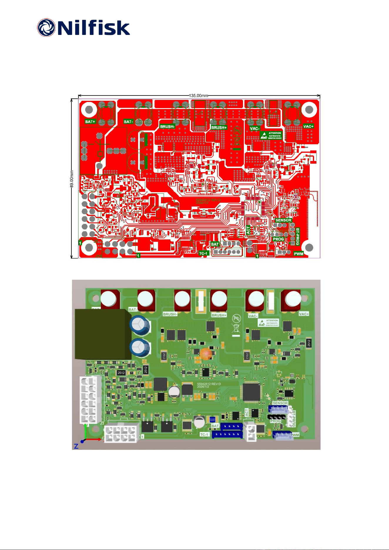
3.1 Dimenion
L=135mm, W=89mm, H=28mm max. Refer to bellow 2D and 3D figures.
Nilfisk A/S Nilfisk Confidential Proprietary
06.05.2026/
DongGuan Page
15
of
16
China
3.2 Others
PCB shows its P/N and lot or production date information on laser code or QR code.
PCB is UL recognized, flammability rated UL-V0 and marked accordingly.
PCBA is protected from moisture effects by coating.
Nilfisk A/S Nilfisk Confidential Proprietary
06.05.2026/
DongGuan Page
16
of
16
China
This device complies with part 15 of the FCC Rules. Operation is subject to the following two
conditions:
(1) This device may not cause harmful interference, and
(2) this device must accept any interference received, including interference that may cause
undesired operation.
Any Changes or modifications not expressly approved by the party responsible for compliance
could void the user's authority to operate the equipment.
Note: This equipment has been tested and found to comply with the limits for a Class B digital
device, pursuant to part 15 of the FCC Rules. These limits are designed to provide reasonable
protection against harmful interference in a residential installation. This equipment generates uses
and can radiate radio frequency energy and, if not installed and used in accordance with the
instructions, may cause harmful interference to radio communications. However, there is no
guarantee that interference will not occur in a particular installation. If this equipment does cause
harmful interference to radio or television reception, which can be determined by turning the
equipment off and on, the user is encouraged to try to correct the interference by one or more of
the following measures:
-Reorient or relocate the receiving antenna.
-Increase the separation between the equipment and receiver.
-Connect the equipment into an outlet on a circuit different from that to which the receiver is
connected.
-Consult the dealer or an experienced radio/TV technician for help.
The device has been evaluated to meet general RF exposure requirement. The device can be
used in portable exposure condition without restriction.