
Models
Heated Holding Cabinet
Instruction Manual
Issued: 6-30-2025
hoshizakiamerica.com
Heated Kitchen Equipment
Steelheart A Series
2
WARNING
Only qualied service technicians should install and service the appliance. To
obtain the name and phone number of your local Hoshizaki Certied Service
Representative, visit www.hoshizakiamerica.com. No installation or service should
be undertaken until the technician has thoroughly read this Instruction Manual.
Likewise, the owner/manager should not proceed to operate the appliance until the
installer has instructed them on its proper operation. Failure to install, operate, and
maintain the appliance in accordance with this manual may adversely affect safety,
performance, component life, and warranty coverage. Proper installation is the
responsibility of the installer. Product failure or property damage due to improper
installation is not covered under warranty.
Hoshizaki provides this manual primarily to assist qualied service technicians in the
installation, maintenance, and service of the appliance.
Should the reader have any questions or concerns which have not been satisfactorily
addressed, please call, send an e-mail message, or write to the Hoshizaki Technical
Support Department for assistance.
Phone: 1-800-233-1940; (770) 487-2331
E-mail: tech-suppor[email protected]
618 Highway 74 South
Peachtree City, GA 30269
Attn: Hoshizaki Technical Support Department
NOTE: To expedite assistance, all correspondence/communication MUST include the
following information:
• Model Number
• Serial Number
• Complete and detailed explanation of the problem.

3
IMPORTANT
This manual should be read carefully before the appliance is installed and
operated. Read the warnings and guidelines contained in this booklet carefully as
they provide essential information for the continued safe use and maintenance of
the appliance. Retain this booklet for any further reference that may be necessary.
CONTENTS
Important Safety Information ................................................................................................. 4
I. Specications ...................................................................................................................... 7
A. Electrical Data ............................................................................................................... 7
1. Solid Doors ............................................................................................................... 7
2. Glass Doors ............................................................................................................. 7
II. Installation Instructions ...................................................................................................... 8
A. Location ........................................................................................................................ 8
B. Checks Before Installation ............................................................................................. 9
C. Setup ........................................................................................................................... 10
D. Door Reversal...............................................................................................................11
1. Full Door Reversal (Solid or Glass) .........................................................................11
2. Half Door Reversal (Solid or Glass) ....................................................................... 14
E. Electrical Connection .................................................................................................. 19
F. Final Checklist .............................................................................................................. 20
III. Operating Instructions ..................................................................................................... 21
A. Important Notes About Usage .................................................................................... 21
B. Startup ...................................................................................................................... 23
C. Controls and Adjustments .......................................................................................... 23
D. Control Module Icons .................................................................................................. 25
E. Food Storage............................................................................................................... 26
F. Alarm Safeties ............................................................................................................. 27
G. Heating Performance .................................................................................................. 28
IV. Cleaning and Maintenance Instructions .......................................................................... 29
A. Cleaning ...................................................................................................................... 29
B. Maintenance ................................................................................................................ 30
V. Preparing the Appliance for Periods of Non-Use ............................................................. 31
VI. Disposal .......................................................................................................................... 32
4
Important Safety Information
Throughout this manual, notices appear to bring your attention to situations which could
result in death, serious injury, damage to the appliance, or damage to property.
DANGER
Indicates a hazardous situation that, if not avoided, will result in
death or serious injury.
WARNING
Indicates a hazardous situation that, if not avoided, could result
in death or serious injury.
NOTICE
Indicates a situation that, if not avoided, could result in damage
to the appliance or property.
IMPORTANT
Indicates important information about the use and care of the
appliance.
DANGER
• Follow handling instructions carefully
in compliance with U.S. government
regulations.
• Component parts shall be replaced with
like components.
• Consult instruction manual/service manual
before attempting to install or service this
product. All safety precautions must be
followed.
• Dispose of properly in accordance with
federal or local regulations.
DANGER
Risque De Feu Ou D'Explosion
Le Frigorigène Est Inammable
• Suivre attentivement les instructions
de manipulation conformément à la
réglementation gouvernementale.
• Les pièces des composants doivent être
remplacées par des pièces et accessoires
équivalents.
• Consulter le manuel du propriétaire/
guide de réparation avant de tenter une
réparation. Toutes les mesures de sécurité
doivent être respectées.
• Éliminer conformément aux règlements
fédéraux ou locaux.
5
WARNING
The appliance should be destined only to
the use for which it has been expressly
conceived. Any other use should be
considered improper and therefore
dangerous. The manufacturer cannot be
held responsible for injury or damage
resulting from improper, incorrect, and
unreasonable use. Failure to install,
operate, and maintain the appliance
in accordance with this manual will
adversely affect safety, performance,
component life, and warranty coverage.
To reduce the risk of death, electric
shock, serious injury, or re, follow
basic precautions including the
following:
• Only qualied service technicians should
install and service the appliance.
• Wear appropriate personal protective
equipment (PPE) when servicing the
appliance.
• The appliance must be installed in
accordance with applicable national, state,
and local codes and regulations.
• Appliance is heavy. Use care when lifting
or positioning. Work in pairs when needed
to prevent injury or damage.
• To reduce the risk of electric shock, do not
touch the plug with damp hands.
• Unplug the appliance before servicing.
• The appliance requires an independent
power supply of proper capacity. See the
nameplate for electrical specications.
Failure to use an independent power
supply of proper capacity can result in a
tripped breaker, blown fuse, damage to
existing wiring, or component failure. This
could lead to heat generation or re.
WARNING, continued
• 115VAC Models: THIS APPLIANCE
MUST BE GROUNDED: This appliance
is equipped with a NEMA 115VAC 5-15
three-prong grounding plug to reduce
the risk of potential shock hazards.
It must be plugged into a properly
grounded, independent 3-prong wall
outlet. If the outlet is a 2-prong outlet, it
is your personal responsibility to have
a qualied electrician replace it with a
properly grounded, independent 3-prong
wall outlet. Do not remove the ground
prong from the plug and do not use an
adapter plug. Failure to follow these
instructions may result in death, electric
shock, or re.
• 208/230VAC Models: THIS APPLIANCE
MUST BE GROUNDED: This appliance
is equipped with a NEMA 208-230
L14-20 four-prong locking, grounding
plug to reduce the risk of potential
shock hazards. It must be plugged into a
properly grounded, independent 4-prong
locking wall outlet. If the outlet is a
3-prong outlet or a 4-prong non-locking
outlet, it is your personal responsibility
to have a qualied electrician replace it
with a properly grounded, independent
4-prong locking wall outlet. Do not
remove the ground prong from the plug
and do not use an adapter plug. After
plugging in, twist the plug clockwise to
lock it into place. Failure to follow these
instructions may result in death, electric
shock, or re.
• Do not use an extension cord.
• Do not use an appliance with a damaged
power cord. The power cord should not
be altered, jerked, bundled, weighed
down, pinched, or tangled. Such actions
could result in electric shock or re.
To unplug the appliance, be sure to pull
the plug, not the cord, and do not jerk
the cord.
6
WARNING, continued
• Do not block air inlets or outlets, otherwise
heating performance may be reduced.
• Do not tightly pack the cabinet. Allow some
space between items to ensure good air
ow. Also allow space between items and
interior surfaces.
• Food storage and handling must comply
with applicable codes and regulations.
• Do not store items near air outlets.
Otherwise, items may scorch and crack
or break causing a risk of injury or
contamination of other food.
• Keep the area around the appliance clean.
Dirt, dust, or insects in the appliance could
cause harm to individuals or damage to
the equipment.
• Do not throw anything onto the shelves
or load any single shelf with more than
120lb. (54.5 kg) of product. They might fall
off and cause injury.
• This appliance is designed for holding
heated prepared foods at a safe
temperature. Use for any other purposes
could cause contamination and
deterioration of stored items.
NOTICE
• Protect the oor when moving the
appliance to prevent damage to the oor.
• Keep ventilation openings clear of
obstruction.
• Care should be used when placing items
on top of the appliance. Foreign objects
or moisture could enter the appliance and
result in electric shock or re.
• To prevent deformation or cracks, do not
spray insecticide onto the plastic parts or
let them come into contact with oil.
• To avoid damage to the gasket, use
only the door handle when opening and
closing.
WARNING, continued
• The GREEN ground wire in the
factory-installed power cord is connected
to the appliance. If it becomes necessary
to remove or replace the power cord, be
sure to connect the power cord's ground
wire.
• Do not splash, pour, or spray water
directly onto or into the appliance. This
might cause short circuit, electric shock,
corrosion, or failure.
• Do not make any alterations to the
appliance. Alterations could result in
electric shock, injury, re, or damage to
the appliance.
• The appliance is not intended for use by
persons (including children) with reduced
physical, sensory, or mental capabilities,
or lack of experience and knowledge,
unless they have been given supervision
or instruction concerning use of the
appliance by a person responsible for
their safety.
• Children should be properly supervised
around the appliance.
• Do not climb, stand, or hang on the
appliance or doors or allow children or
animals to do so. Do not climb into the
appliance or allow children or animals to
do so. Death or serious injury could occur
or the appliance could be damaged.
• Be careful not to pinch ngers when
opening and closing the doors or when
handling food pans. Be careful when
opening and closing the doors when
children are in the area.
• Open and close the doors with care.
Opening the doors too quickly or forcefully
may cause injury or damage to the
appliance or surrounding equipment.
• Do not use combustible spray or place
volatile or ammable substances in or
near the appliance. They might catch re.
• Do not place any product on the oor of
the cabinet. All product must be placed on
properly installed shelves.
7
I. Specications
A. Electrical Data
The nameplate provides electrical and refrigerant data. The nameplate is located on the
upper part of the left side panel. For certication marks, see the nameplate.
We reserve the right to make changes in specications and design without prior notice.
1. Solid Doors
MODEL NUMBER HC1A-FS(-HS) HC1A-FS-FS(-HS-HS)
AC SUPPLY VOLTAGE 115/60/1 115/60/1
AMPERES 10.0 AMPS 10.0 AMPS
MAX. HACR BREAKER 15 15
EQUIPPED WITH PLUG NEMA 5-15 NEMA 5-15
Model Number HC2A-FS(-HS) HC2A-FS-FS(-HS-HS)
AC SUPPLY VOLTAGE 208-230/60/1 208-230/60/1
AMPERES 9.0/10.0 AMPS 9.0/10.0 AMPS
MAX. HACR BREAKER 20 20
EQUIPPED WITH PLUG NEMA L14-20
NEMA L14-20
2. Glass Doors
Model Number HC1A-FGE(-HGE) HC1A-FGE-FGE(-HGE-HGE)
AC SUPPLY VOLTAGE 115/60/1 115/60/1
AMPERES 10.0 AMPS 10.0 AMPS
MAX. HACR BREAKER 15 15
EQUIPPED WITH PLUG NEMA 5-15 NEMA 5-15
Model Number HC2A-FGE(-HGE) HC2A-FGE-FGE(-HGE-HGE)
AC SUPPLY VOLTAGE 208-230/60/1 208-230/60/1
AMPERES 9.0/10.0 AMPS 9.0/10.0 AMPS
MAX. HACR BREAKER 20 20
EQUIPPED WITH PLUG NEMA L14-20 NEMA L14-20
8
II. Installation Instructions
WARNING
• This appliance must be installed in accordance with all applicable national, state,
and local regulations.
• Appliance is heavy. Use care when lifting or positioning. Work in pairs when
needed to prevent injury or damage.
• Do not tilt the appliance more than 45°.
A. Location
WARNING
• This appliance is not intended for outdoor use.
• Normal operating ambient temperature:
– Heated Holding Cabinet 45°F to 104°F (7°C to 40°C)
Operation of the appliance, for extended periods, outside of this normal
temperature range may affect appliance performance.
For best operating results:
• The location should provide a rm and level foundation for the appliance.
• The appliance should not be located in a corrosive environment.
• Minimum Clearance:
Models Side Top Rear
All Heated Holding Cabinets 0" (0 cm) 0" (0 cm) 0" (0 cm)
Pass-Thru's 0" (0 cm) 0" (0 cm) N/A
9
B. Checks Before Installation
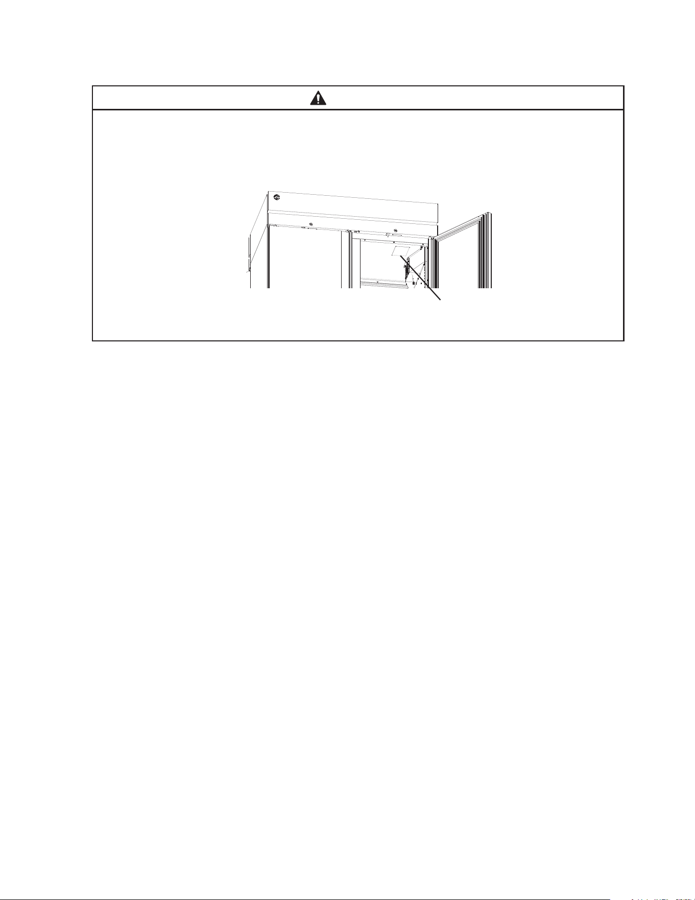
WARNING
Refer to the nameplate for electrical specications. See Fig. 1. The nameplate
is located on the front right side of the top panel. For more electrical connection
details, see "I.E. Electrical Connection." We reserve the right to make specication
and design changes without prior notice.
• Visually inspect the exterior of the shipping package and immediately report any damage
to the carrier. Upon opening the package, any concealed damage should also be
immediately reported to the carrier.
• Remove the shipping carton, tape, and packing material. Remove the protective plastic
lm from the exterior panels on all models. If the appliance is exposed to the sun or to
heat, remove the lm after the appliance cools.
• Remove all accessory containers before discarding the packing materials. Dispose of all
packing materials in a proper and environmentally responsible manner.
• Check for missing or damaged accessories.
Fig. 1
Model Shown: HC2A-FS-FS(-HS-HS)
Nameplate
10
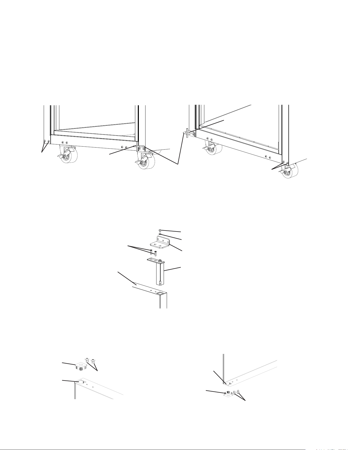
b) Legs: Optional 6 in. legs available. Attach and tighten the optional adjustable 6 in. legs
to the bottom of the appliance.
WARNING
When using legs, avoid sliding the appliance across the oor after legs are installed.
b) Leveling the Appliance
After installing the casters or optional 6 in. legs, lower the appliance to the oor and
check the level of the appliance.
a) Casters: If the appliance is out of level, follow the instructions and steps found in
HS-3590 provided in the accessories bag. Otherwise, continue to the next section.
NOTICE! Make sure the casters are tight and no gap is left between the casters,
shim plates, and appliance.
b) Legs: If the appliance is out of level, turn the bottom portion of the leg for height
adjustment. Otherwise, continue to the next section. NOTICE! Make sure the legs
are tight and no gap is left between the leg and appliance.
2. Install the Shelves
Shelf support clips are provided in the accessory pack.
1) Place the shelf support clips into the pilasters (4 shelf
support clips per shelf). Indexing holes are provided on the
pilasters in evenly spaced intervals to assist in positioning
the support clips at the same height. See Fig. 3.
2) Place the shelves in position on the shelf support clips.
C. Setup
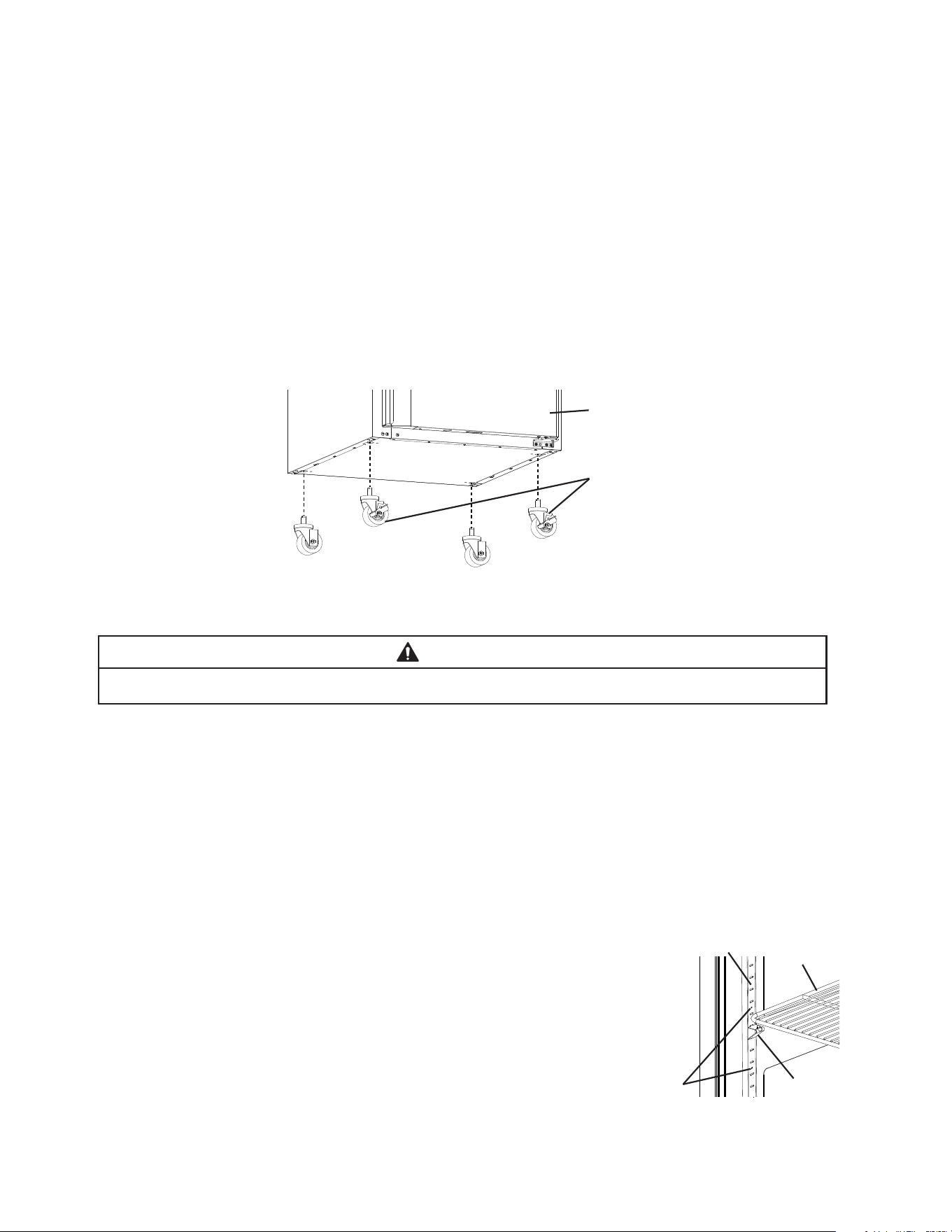
1. Caster or Optional 6 in. Leg Installation and Leveling the Appliance
a) Caster or Optional 6 in. Leg Installation
1) Move as close to the nal location as possible.
2) Remove the 2 bolts securing the appliance to the pallet, then remove the appliance
from the pallet. Block the appliance securely at a height of 8 in. (20cm) off the oor.
Do not lay the appliance down. NOTICE! Do not allow the door(s) to bear the weight
of the appliance.
a) Casters: Attach and tighten the casters to the bottom of the appliance. Locking casters
should be attached to the front of the appliance for standard models and on the
service (control module) side on pass-thru models. See Fig. 2.
NOTICE! Ensure casters are completely threaded into appliance and tight.
Fig. 2
Shelf
Support
Clip
Indexing
Holes
Pilaster
Shelf
Fig. 3
Front of Appliance (standard models)
or Service (control module) Side
(pass-thru models)
Locking Casters
11
D. Door Reversal
This appliance is provided with a cabinet design which, after being delivered to the
installation location, permits changing of the door swing from left to right or right to left.
WARNING
• Wear proper PPE (personal protection equipment) when executing these
procedures (safety glasses and gloves).
• Keep ngers away from edge of upper hinge bracket. Spring cartridge can cause
the upper hinge bracket to move suddenly with extreme force.
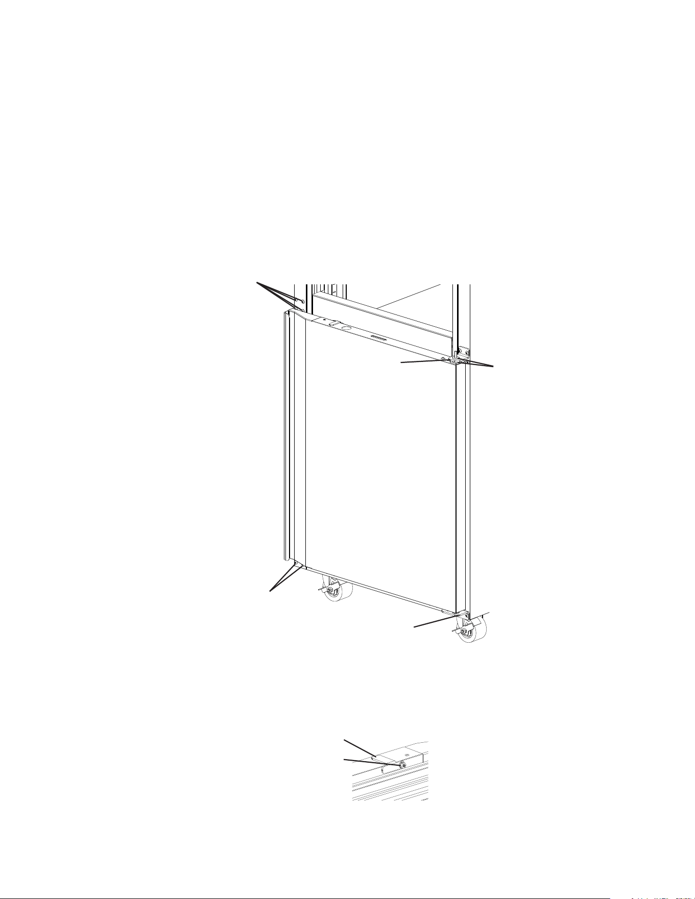
1. Full Door Reversal (Solid or Glass)
Note: Hinge brackets and spring cartridge are universal and can be used in both left and
right-hinged applications.
Example shows change from right-hinged to left-hinged.
1) Lock the casters.
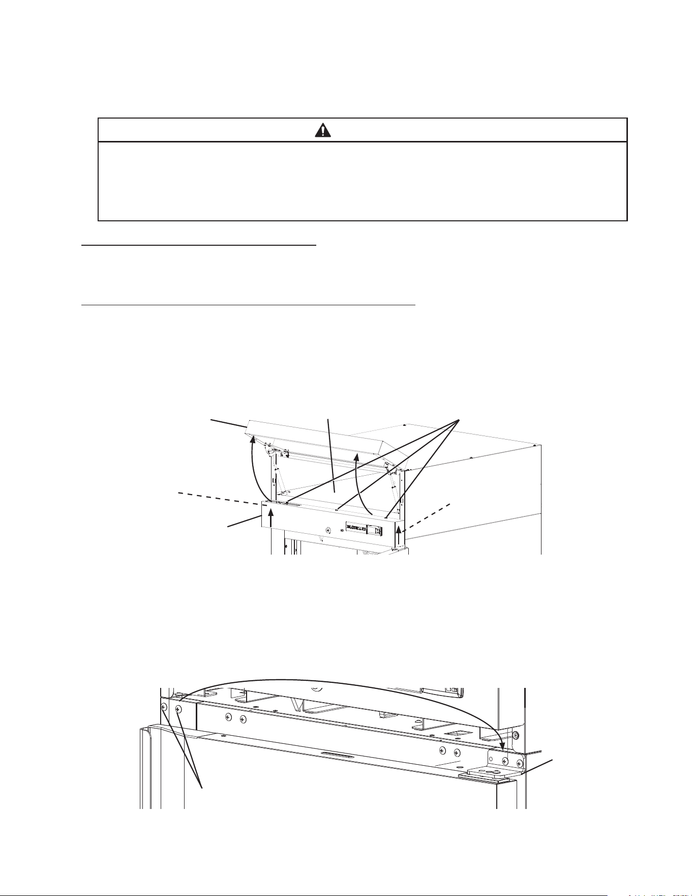
2) Raise the front panel, then remove the control panel screws. Next, lift the control panel
up and lift off of the control panel collars. Be careful not to pull the wires on the control
module and door switch(es), remove the control panel and place in the holding area
above the control panel. See Fig. 4.
3) While maintaining a hold on the door, remove the upper hinge bracket, then lift the door
up off the bottom hinge and set aside. See Fig. 5. Remove the ller screws from the
opposite side upper hinge bracket holes and mount them into the holes of the removed
upper hinge bracket. NOTICE! Be sure to reuse the bracket screws for mounting the
bracket as the bracket screws are 5×12 and ller screws are 5×10.
Filler Screws
Upper Hinge
Bracket
Fig. 5
Fig. 4
Front Panel
Control Panel
Control Panel
Screws
Holding Area
Control Panel
Collar
Control Panel
Collar
12
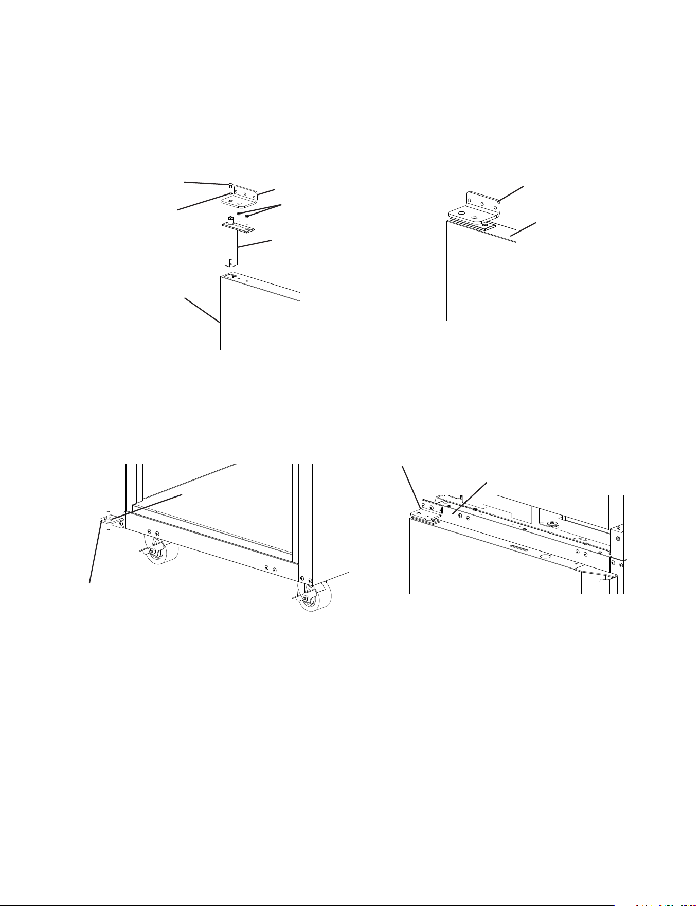
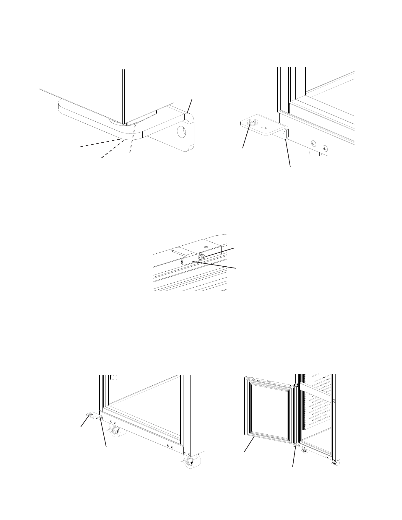
4) Remove the lower hinge bracket and thrust washer. See Fig. 6. Retain thrust washer
for opposite side lower hinge bracket installation. Remove the ller screws from the
opposite side lower hinge bracket holes and mount them into the holes of the removed
lower hinge bracket. NOTICE! Be sure to reuse the bracket screws for mounting the
bracket as the bracket screws are 5×12 and ller screws are 5×10.
5) Secure the lower hinge bracket to the opposite side lower hinge bracket location, then
place the thrust washer on the lower hinge bracket. See Fig. 7.
6) Remove the screw and washer securing the upper hinge bracket to the spring cartridge.
Remove the 2 screws securing the spring cartridge to the door, then remove the spring
cartridge from the door. See Fig. 8.
7) Rotate the door 180 degrees, to its new orientation. Remove the nylon bearing and ller
screws. See Fig. 9. NOTICE! Care should be taken not to damage the door. Mount
the nylon bearing and ller screws into the holes left by the spring cartridge in the lower
section of the door. See Fig. 10.
Nylon Bearing
Filler Screws
Filler Screws
Nylon Bearing
Nylon Bearing Hole
Formerly Spring
Cartridge Hole
Fig. 9 Fig. 10
Fig. 8
Upper Hinge Bracket Screw
Upper Hinge Bracket
Spring Cartridge
Door
Spring Cartridge Screws
Upper Hinge Bracket Washer
Fig. 6
Fig. 7
Lower Hinge
Bracket
Thrust
Washer
Thrust
Washer
Filler
Screws
Filler Screws
13
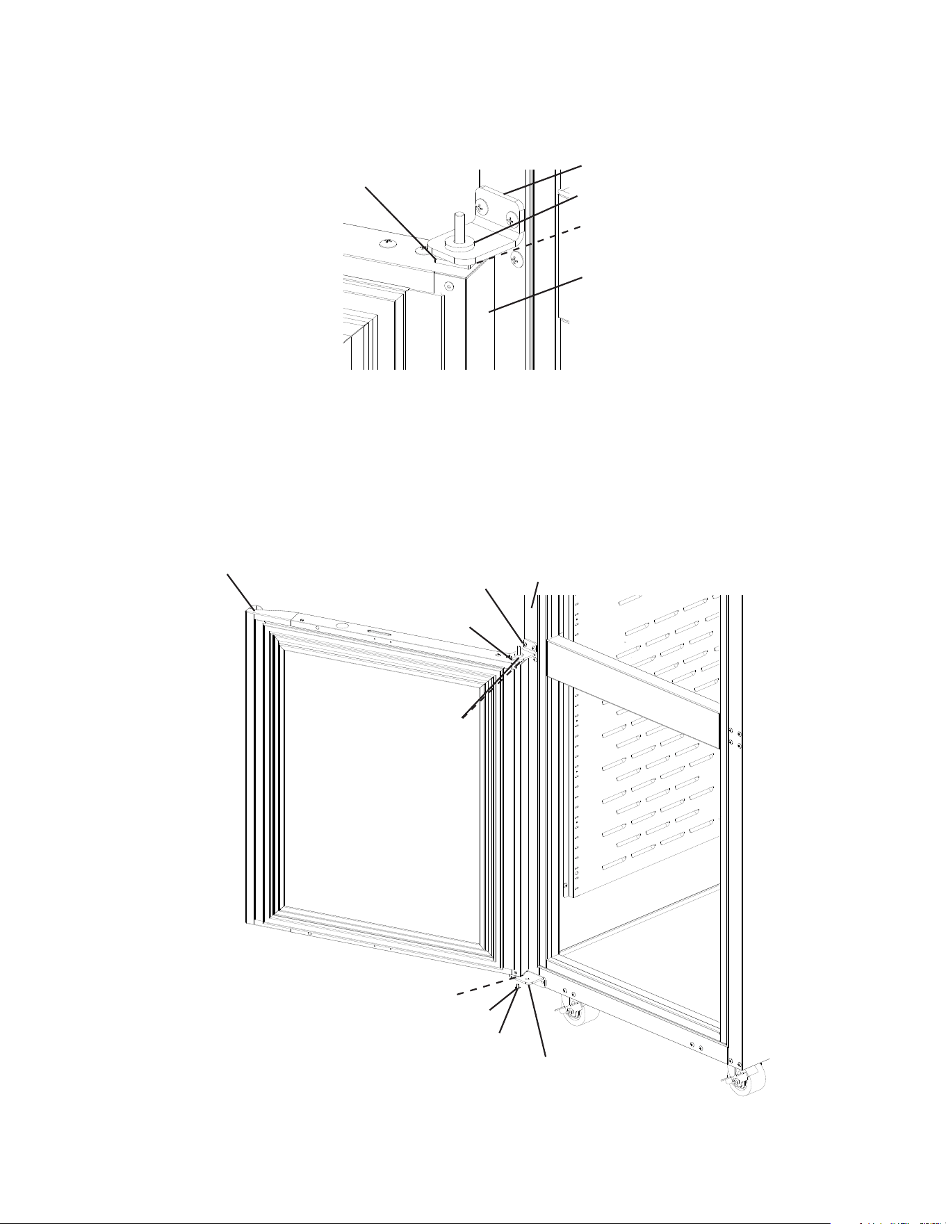
8) Clear foam from the spring cartridge hole to allow for spring cartridge installation. Install
the spring cartridge and secure it to the door using the spring cartridge screws removed
in step 6. See Fig. 11. Next, align the upper hinge bracket to the door in the orientation
that allows for closed door installation. See Fig. 12. Secure the upper hinge bracket to
the door using the screw and washer removed in step 6.
9) Make sure the thrust washer is in place, then mount the door onto the lower hinge
bracket (nylon bearing over lower hinge bracket pin). See Fig. 13.
10) Secure the upper hinge bracket to the appliance. See Fig. 14.
Fig. 13
Lower Hinge
Bracket
Thrust
Washer
Fig. 14
Upper Hinge Bracket
Cabinet
Fig. 11
Fig. 12
Upper Hinge
Bracket Screw
Upper Hinge Bracket
Spring Cartridge
Door
Spring Cartridge Screws
Upper Hinge
Bracket Washer
Upper Hinge Bracket
Door
11) Verify the door swing. Move the control panel hole plugs to the other side, then replace
and secure the control panel and front panel in their correct positions. Verify the door
switch and lock function.
14
2. Half Door Reversal (Solid or Glass)
Note: Hinge brackets and spring cartridge are universal and can be used in both left and
right-hinged applications.
Example shows change from right-hinged to left-hinged.
1) Lock the casters.
2) Raise the front panel, then remove the control panel screws. Next, lift the control panel
up and lift off of the control panel collars. Be careful not to pull the wires on the control
module and door switch(es), remove the control panel and place in the holding area
above the control panel. See Fig. 15.
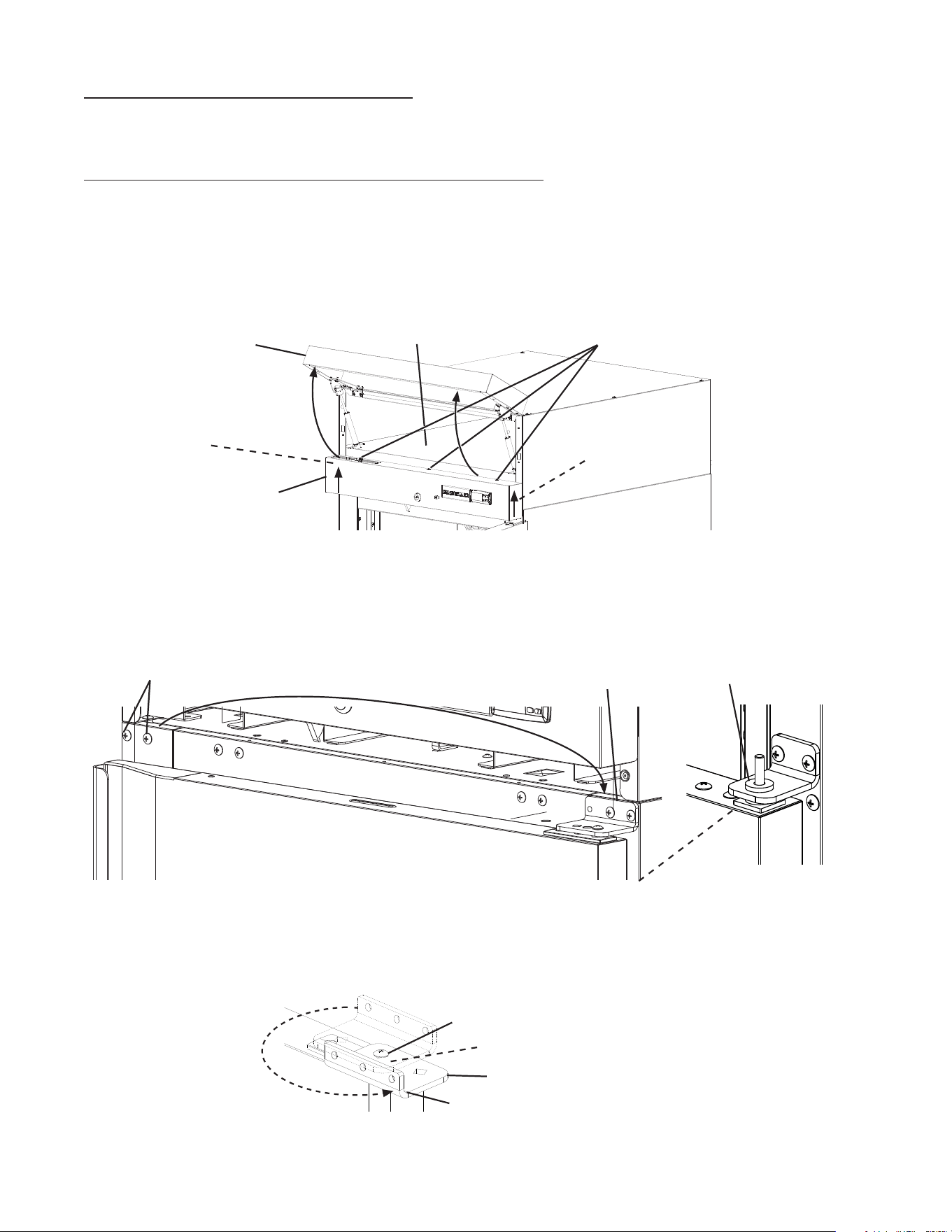
3) While maintaining a hold on the upper door, remove the upper hinge bracket then lift
the door off the center hinge bracket. See Fig. 16. Retainthe upper center hinge bracket
thrust washer for opposite side hinge bracket installation.
4) Rotate the upper hinge bracket 180 degrees counter clockwise. SeeFig.17.
Next, remove the spring cartridge screw and washer, then remove the upper hinge
bracket and thrust washers (2). Set the door aside. Retainthe upper hinge bracket
thrust washers for opposite side hinge bracket installation.
Fig. 17
Spring Cartridge Screw and Washer
Rotate 180
degrees CCW
Thrust Washers (2)
Upper Hinge Bracket
Fig. 16
Center Hinge
Bracket Upper
Thrust Washer
Fig. 15
Filler Screws
Upper Hinge Bracket
Front Panel
Control Panel
Control Panel
Screws
Holding Area
Control Panel
Collar
Control Panel
Collar
15
5) Remove the ller screws from the opposite side upper hinge bracket holes and mount
them into the holes of the removed upper hinge bracket. NOTICE! Be sure to reuse the
hinge bracket screws for mounting the hinge bracket as the hinge bracket screws
are 5×12 and ller screws are 5×10.
6) While maintaining a hold on the lower door, remove the lower hinge bracket from the
cabinet, then lower the door off the center hinge bracket and set aside. SeeFig. 18.
Retainthe center hinge thrust washers for opposite side installation.
7) Remove the center hinge bracket from the cabinet. Remove the ller screws from the
opposite side lower and center hinge bracket holes and mount them into the holes of
the removed lower and center hinge brackets. NOTICE! Be sure to reuse the hinge
bracket screws for mounting the hinge brackets as the hinge bracket screws are
5×12 and ller screws are 5×10.
8) Remove the door latch from the lower door. See Fig. 19.
Fig. 19
Latch
Screw-Bolt with Threadlocker
(5×16, SS)
Fig. 18
Center Hinge
Bracket
Filler Screws
Filler Screws
Lower Hinge Bracket
Thrust Washers
16
9) Remove the lower hinge bracket spring cartridge screw, washer, and thrust washers
from the door. Set the door aside. Next, secure the lower hinge bracket to the opposite
side. Make sure the lower thrust washers are in place. See Fig. 20.
10) Rotate the former upper door 180 degrees to its new lower door orientation.
NOTICE! Care should be taken not to damage the door.
11) Attach the lower door latch to the newly rotated lower door (former rotated upper door).
See Fig. 21.
12) Make sure the lower hinge bracket thrust washers (2) are in place, then with the lower
door (former rotated upper door) in the maximum open position, place the door onto the
lower hinge bracket. See Fig. 22. The spring cartridge shaft should slide into the lower
hinge bracket and be ush with the bottom of the lower hinge bracket.
Lower Hinge Bracket
Fig. 22
Thrust Washers (2)
Lower Hinge Bracket
Lower Door
Latch
Screw-Bolt with Threadlocker
(5×16, SS)
Fig. 21
Fig. 20
Washer
Spring Cartridge Screw
Thrust Washers (2)
Lower Hinge Bracket
Lower Hinge Bracket
Thrust Washers (2)
17
13) Place the center hinge bracket lower pin with thrust washer into the nylon bearing on
top of the door. Secure the center hinge bracket to the cabinet. See Fig. 23.
14) Secure the door to the lower hinge bracket using the spring cartridge screw and washer.
Note: Be sure thrust washers (2) are in place between lower hinge bracket and door.
See Fig 24.
15) Verify the door swing.
Washer
Spring Cartridge Screw
Center Hinge Bracket
Thrust Washers
Lower Hinge Bracket
Nylon Bearing
Cabinet
Thrust Washers (2)
Lower Door
Fig. 24
Fig. 23
Center Hinge Bracket
Nylon Bearing
Lower Door
Thrust Washers (2)
Thrust Washer
18
16) Make sure the center hinge bracket upper thrust washer is in place on top of the center
hinge bracket upper pin.
17) Align the upper hinge bracket to the upper door in the orientation that allows for closed
door installation. Make sure the thrust washers are in place between the upper hinge
bracket and upper door, then secure the upper hinge bracket to the door using the
spring cartridge screw and washer removed earlier in step 9. The spring cartridge shaft
should slide into the upper hinge bracket and be ush with the top of the doors upper
hinge bracket.
18) With the door in the closed position, place the upper doors nylon bearing onto the
center hinge bracket upper pin, then secure the upper hinge bracket to the cabinet with
the upper door in the closed position. See Fig. 25.
19) Verify the door swing. Move the control panel hole plugs to the other side, then replace
and secure the control panel in its correct position, then lower the front panel in its
correct position. Verify the door switch and lock function and adjust as necessary.
Upper Door
Upper Hinge Bracket
Washer
Spring Cartridge Screw
Thrust Washers (2)
Center Hinge Bracket
Nylon Bearing
Thrust Washer
Upper Hinge Bracket
Mounting Screws
Fig. 25
Cabinet
Lower Door
Front Panel
Control Panel
19
E. Electrical Connection
WARNING
• Electrical connection must meet national, state, and local electrical code
requirements. Failure to meet these code requirements could result in death,
electric shock, serious injury, re, or severe damage to equipment.
• This appliance requires an independent power supply of proper capacity. See
the nameplate for electrical specications. Failure to use an independent power
supply of proper capacity can result in a tripped breaker, blown fuse, damage to
existing wiring, or component failure. This could lead to heat generation or re.
• 115VAC Models: THIS APPLIANCE MUST BE GROUNDED: This appliance is
equipped with a NEMA 115VAC 5-15 three-prong grounding plug to reduce
the risk of potential shock hazards. It must be plugged into a properly grounded,
independent 3-prong wall outlet. If the outlet is a 2-prong outlet, it is your personal
responsibility to have a qualied electrician replace it with a properly grounded,
independent 3-prong wall outlet. Do not remove the ground prong from the plug
and do not use an adapter plug. Failure to follow these instructions may result in
death, electric shock, or re.
• 208/230VAC Models: THIS APPLIANCE MUST BE GROUNDED: This appliance
is equipped with a NEMA 208-230 L14-20 four-prong locking, grounding plug
to reduce the risk of potential shock hazards. It must be plugged into a properly
grounded, independent 4-prong locking wall outlet. If the outlet is a 3-prong
outlet or a 4-prong non-locking outlet, it is your personal responsibility to have
a qualied electrician replace it with a properly grounded, independent 4-prong
locking wall outlet. Do not remove the ground prong from the plug and do not use
an adapter plug. After plugging in, twist the plug clockwise to lock it into place.
Failure to follow these instructions may result in death, electric shock, or re.
• To reduce the risk of electric shock, do not touch the plug with damp hands.
• Press and hold the standby button to turn "OFF" before unplugging the appliance
to reduce the risk of electric shock.
• Do not use an extension cord.
• Do not use an appliance with a damaged power cord. The power cord should not
be altered, jerked, bundled, weighed down, pinched, or tangled. Such actions
could result in electric shock or re. To unplug the appliance, be sure to pull the
plug, not the cord, and do not jerk the cord.
• The GREEN ground wire in the factory-installed power cord is connected to the
appliance. If it becomes necessary to remove or replace the power cord, be sure
to connect the power cord's ground wire.
• Usually an electrical permit and services of a licensed electrician are required.
• The maximum allowable voltage variation is ±10 percent of the nameplate rating.

20
F. Final Checklist
1) Is the appliance level?
2) Are the legs or casters properly tightened to the appliance?
3) If using casters, have the front casters been locked?
4) Is the appliance in a site where the ambient temperature is as specied below all year
around?
– Heated Holding Cabinet 45°F to 104°F (7°C to 40°C)
5) Has the shipping carton, tape, and packing material been removed from the appliance?
Hasthe protective plastic lm been removed from the exterior panels on all models and
from the interior door panels on solid door models?
6) Has the appliance and accessories been checked for shipping damage?
7) Has the power supply voltage been checked or tested against the nameplate rating?
Is the power supply a properly grounded, independent wall outlet? Does the electrical
connection meet all national, state, and local code and regulation requirements?
8) Have the shelves been properly installed?
9) Has the humidity vent been properly set?
10) Has the end user been given the instruction manual, instructed on how to operate the
appliance, and given the importance of the recommended periodic maintenance?
11) Has the end user been given the name and telephone number of an authorized service
agent?
12) Has the warranty card been lled out and forwarded to the factory for warranty
registration?
21
III. Operating Instructions
A. Important Notes About Usage
WARNING, continued
• Children should be properly supervised
around the appliance.
• Do not climb, stand, or hang on the
appliance or doors or allow children or
animals to do so. Do not climb into the
appliance or allow children or animals to
do so. Death or serious injury could occur
or the appliance could be damaged.
• Be careful not to pinch ngers when
opening and closing the doors. Be careful
when opening and closing the doors when
children are in the area.
• Open and close the doors with care.
Opening the doors too quickly or forcefully
may cause injury or damage to the
appliance or surrounding equipment.
• Keep the area around the appliance clean.
Dirt, dust, or insects in the appliance
could cause harm to individuals or
damage to the equipment.
• Do not throw anything onto the shelves
or load any single shelf with more than
120lb. (54.5 kg) of product. They might fall
off and cause injury.
• Do not block air inlets or outlets, otherwise
heating performance may be reduced.
• Do not tightly pack the cabinet. Allow
some space between items to ensure
good air ow. Also allow space between
items and interior surfaces.
• Food storage and handling must comply
with applicable codes and regulations.
• Do not place any product on the oor of
the cabinet. All product must be placed on
properly installed shelves.
WARNING
• Some surfaces are hot, care should be
taken to avoid burns.
• Only qualied service technicians should
install and service the appliance.
• Wear appropriate personal protective
equipment (PPE) when handling hot
pans or product and when servicing the
appliance.
• Failure to install, operate, and maintain
the appliance in accordance with this
manual may adversely affect safety,
performance, component life, and
warranty coverage.
• To reduce the risk of electric shock, do
not touch the plug with damp hands.
• Do not splash, pour, or spray water
directly onto or into the appliance. This
might cause short circuit, electric shock,
corrosion, or failure.
• The appliance is not intended for use by
persons (including children) with reduced
physical, sensory, or mental capabilities,
or lack of experience and knowledge,
unless they have been given supervision
or instruction concerning use of the
appliance by a person responsible for
their safety.
• Care should be used when placing items
on top of the appliance. Foreign objects
or moisture could enter the appliance and
result in electric shock or re.
22
WARNING, continued
• This appliance is designed for keeping
food items warm until served.
• Do not use this cabinet to heat COLD
foods. Holding food at temperatures
of less than 140°F (60°C) may be
dangerous. Temperatures under 140°F
(60°C) promote the growth of harmful
bacteria and toxins in some foods.
• The temperature danger zone is
considered 40°F to 140°F (4.4°C to
60°C) and rapid bacteria growth zone is
considererd 70°F to 120°F (21°C to 49°C).
• Prevent potentially hazardous foods
from spending more than four (4) hours
combined total time in these zones.
• Employ sanitary methods. Use for any
other purposes could cause deterioration
of stored items and contamination of
items.
NOTICE
• Protect the oor when moving the
appliance to prevent damage to the oor.
• Keep ventilation openings, in the
appliance enclosure or in the built-in
structure, clear of obstruction. Blockage of
airow could negatively affect performance
and damage the appliance.
• To prevent deformation or cracks, do not
spray insecticide onto the plastic parts or
let them come into contact with oil.
• To avoid damage to the gasket, use
only the door handle when opening and
closing.
• Do not leave the doors open.
23
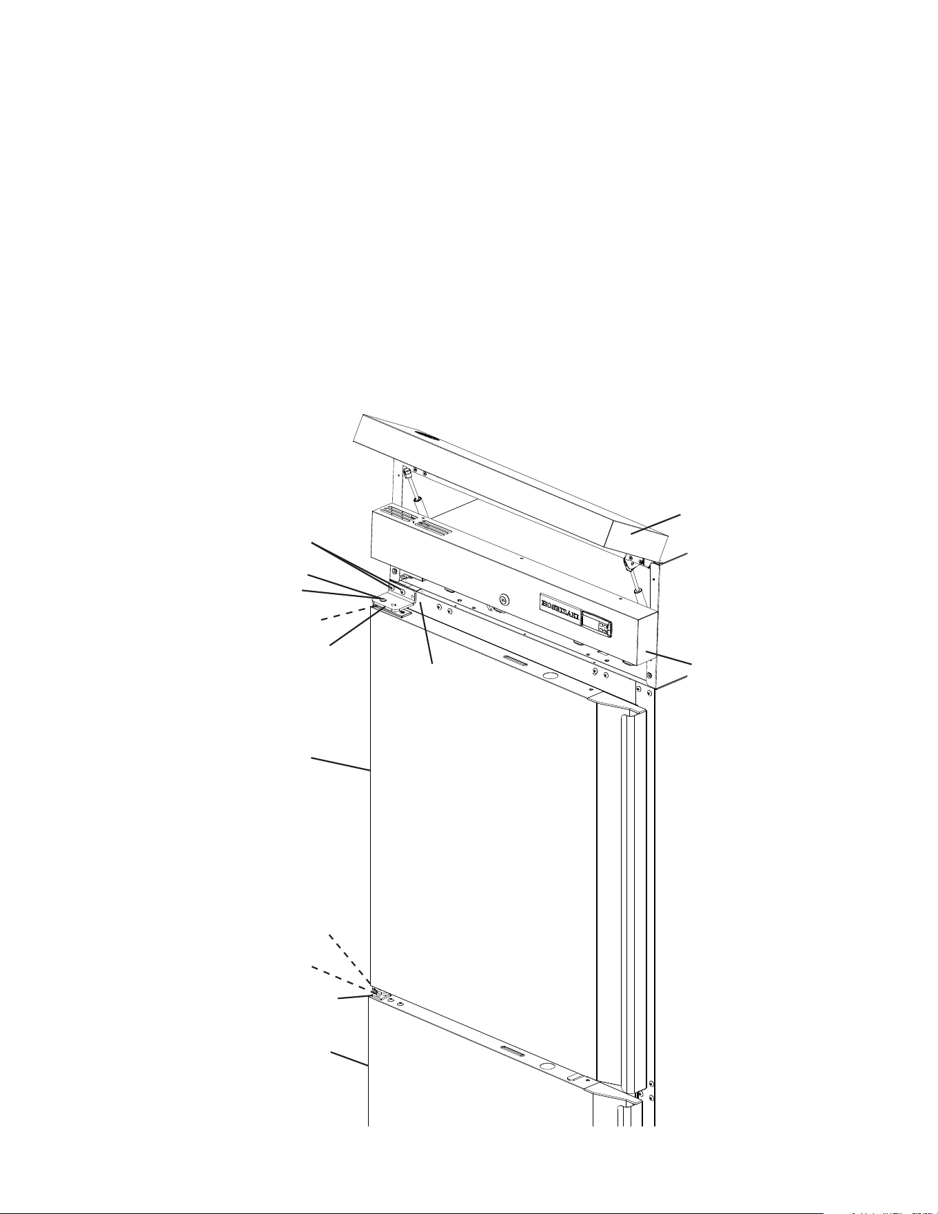
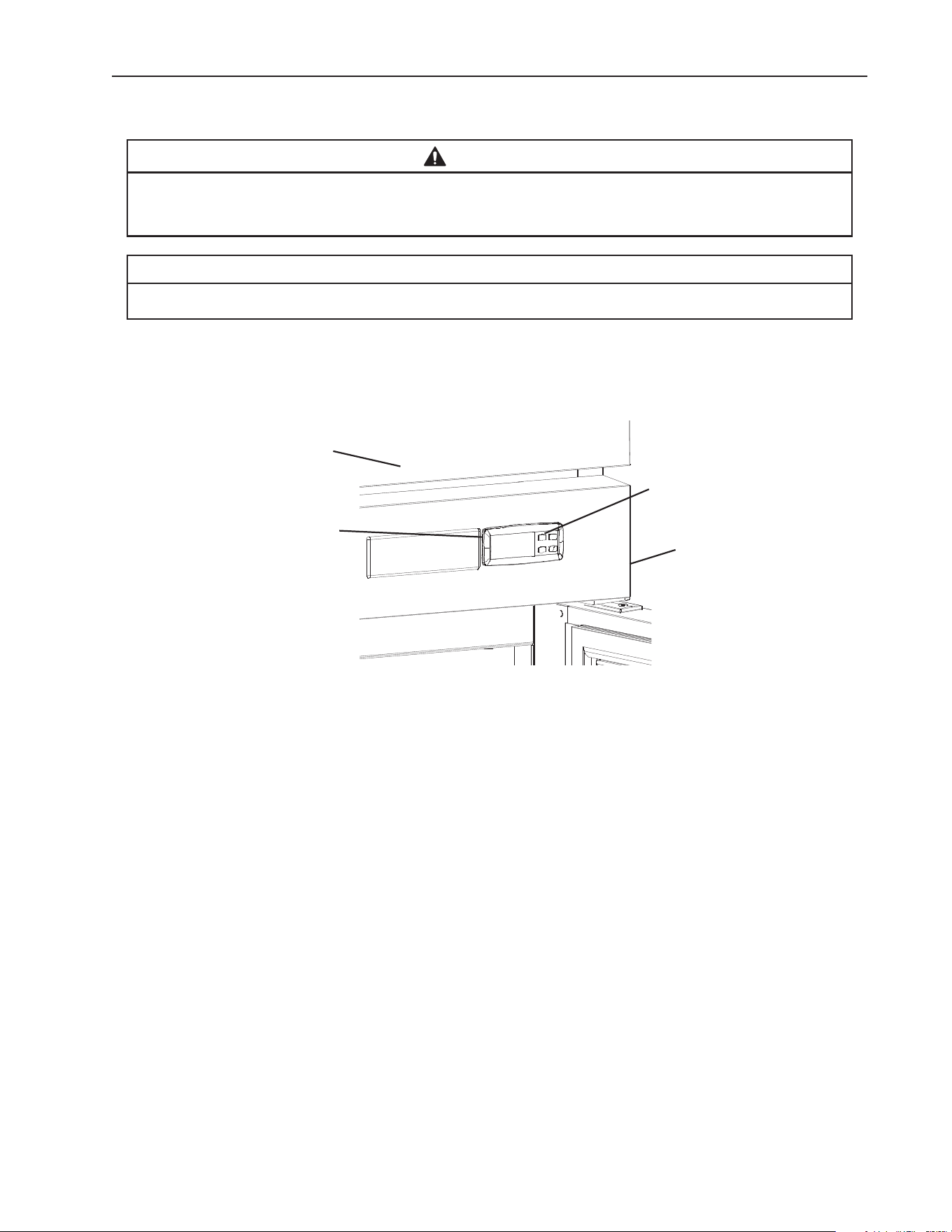
B. Startup
WARNING
• All parts are factory-adjusted. Improper adjustments may adversely affect
safety, performance, component life, and warranty coverage.
• To reduce the risk of electric shock, do not touch the plug with damp hands.
1) Plug the appliance into the electrical outlet. At startup, there is a slight delay before the
heater(s) start. WARNING! To reduce the risk of electric shock, do not touch the
plug with damp hands.
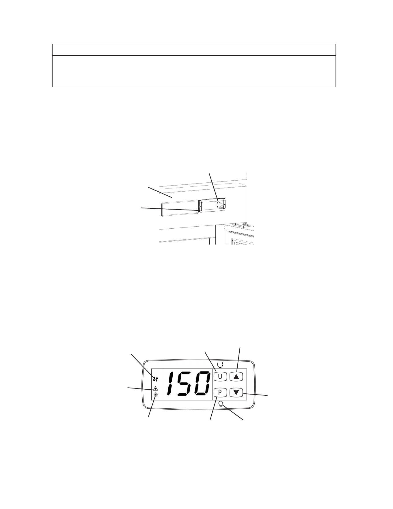
2) If the cabinet temperature is not displayed on the control module, press and hold the "U"
button (on/off button) for 2seconds. See Fig. 26.
3) Allow the appliance to heat up prior to loading it with food products.
Fig. 27
Control
Module
Front Panel
"U" Button
Fig. 26
C. Controls and Adjustments
1. Temperature Display
The cabinet temperature is displayed on the control module. See Fig. 27.
The display is in °F. To convert from °F to °C, see “II.C.3. Changing the Temperature
Display Scale (°F or °C).”
Service Button and
LED Light Switch for
Glass Door Models
Down Button
On/Off
Button
Up Button
"Fan Motor"
Icon
"Alarm"
Icon
"Heater" Icon
"LED Light" Icon
(glass door models only)

24
2. Adjusting the Temperature Setpoint
The temperature setpoint is the value for the cabinet temperature. The temperature
differential for the heater(s) to turn on or off is ±1.5°F (±0.8°C) of the temperature setpoint.
For example, the temperature setpoint of 150°F (65.5°C), the heater(s) come on at
148.5°F (64.7°C) and the heater(s) go off at 151.5°F (66.3°C). If necessary, adjust the
temperature setpoint as follows:
1) To change the temperature setpoint, press and release the "P" button or the up or down
button. The current temperature setpoint appears. Press the up or down button until
the desired value is displayed. After a few seconds, the display returns to the current
cabinet temperature and the temperature setpoint is saved.
• Heated Holding Cabinet temperature setpoint is adjustable between 80°F and 180°F
(26.6°C and 82.2°C). The factory default is 150°F (65°C).
3. Changing the Temperature Display Scale (°F or °C)
There are 4 temperature display settings from which to choose.
The factory temperature display default is F0 for °F whole number.
For a whole number temperature display scale value, select F0 or C0.
For a temperature display scale value to one decimal point, select F1 or C1.
Display Setting Temperature Display Example
F0 - Factory Default 150°F
C0 65°C
F1 150.0°F
C1 65.0°C
To change the temperature display setting, follow the steps below.
1) Press the “U” and “P” buttons together for 5 seconds. I.uP is displayed.
2) Press the “P” button. The current display setting (F0, F1, C0, or C1) and I.uP start
ashing.
3) Press the up or down button until the desired temperature display setting appears.
4) Press the “P” button to save the selection. I.uP is displayed. To return to normal display
mode, press and hold the “U” button for 5 sec. Display returns to normal display mode.
If no other button is pressed after pressing the “P” button, 25 sec. later, display returns
to normal display mode.
Note: If no selection is saved within 30 seconds, the display returns to normal mode
and the temperature display setting remains unchanged.
25
Fig. 28
Up Button
Down Button
On/Off
Button
"Heater" Icon
"Alarm" Icon
"Fan Motor"
Icon
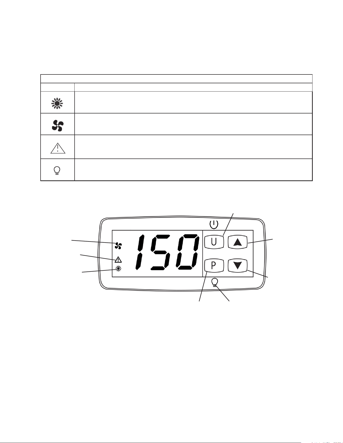
D. Control Module Icons
Control module icons inform you of energized components and if the appliance is in
alarm. Note: Icons ash when components are called for during a timed lockout or the
door is open. Once the timer terminates or the door is closed, the icons go solid and
components energizes. See Fig. 28.
Control Module Icons
Icon Meaning
Heater(s)
Heater(s) energized. Heater(s) de-energize when door is open.
Fan Motor
Fan motor energized. Fan motor de-energizes when door is open.
Alarm
Appliance is in alarm. See "II.G. Alarm Safeties" for details.
LED Light (glass door models)
Glass door cabinet LED light. The cabinet LED light is controlled by the "P" service button.
Service Button and
LED Light Switch for
Glass Door Models
"LED Light" Icon
(glass door models only)

26
E. Food Storage
WARNING
• This appliance is designed for storage of pre-cooked food. Employ sanitary
methods.
• Holding food at temperatures of less than 140°F (60°C) may be dangerous.
Temperatures under 140°F (60°C) promote the growth of harmful bacteria and
toxins in some foods.
• Do not block the cabinet air inlet or outlet, otherwise heating performance may be
reduced.
• Do not tightly pack the cabinet. Allow some space between items to ensure good
air ow. Also allow space between items and interior surfaces.
• Do not place any product on the oor of the cabinet. All product must be placed on
properly installed shelves.
• Do not put cool or uncooked foods in the cabinet. Cook them rst, or they will
lower the cabinet temperature and could deteriorate other foods in the cabinet or
overload the appliance.
• All foods should be wrapped in heat resistant wrap or stored in sealed containers.
Otherwise foods may dry up, pass their smells onto other foods, result in poor
appliance performance, or increase the likelihood of cross-contamination.
• Do not store items near the air outlet. They might dry out and crack or break
causing a risk of injury or contamination of other food.

27
F. Alarm Safeties
Alarm signals are designed to protect the appliance and food product. These alarms
give information or warnings in the event the appliance is operating out of acceptable
parameters. Should one of the alarms occur, follow the instructions in the table below to
address the alarm. The alarm code and alarm icon ash with audible alarm.
Alarm Signals
Alarm Code Problem Corrective Action/Reset Details
oP
Door Switch Alarm: Door has
remained open for more than 2
minutes.
Door Is Open or The Door Switch
has failed.
If obvious corrections such as closing doors does not
correct the alarm, call a qualied service technician.
Beeps continuously after 2 min.
To silence the alarm, press and release any button.
(-)E1
Cabinet Thermistor Malfunction
Alarm
Cabinet thermistor has failed.
Call a qualied service technician.
Beeps continuously. To silence the alarm, press and
release the up button.
Appliance cycles 1 min. on, 10 min. off.
-E1 - Cabinet thermistor out of place or open.
E1 - Cabinet thermistor shorted.
Hi
High Temperature Alarm
Cabinet temperature has remained
above 225°F (107.2°C) for more than
2minutes.
If obvious corrections do not bring temperature back
in range, call a qualied service technician.
Beeps continuously.
To silence the alarm and clear "Hi" from the display,
press and release any button. The alarm icon stays
on.
Automatically resets when temperature returns to
normal.
Lo
Low Temperature Alarm
Cabinet temperature has remained
below 80°F (26.6°C) for more than
2minutes.
If obvious corrections do not bring the temperature
back in range, call a qualied service technician.
Beeps continuously.
To silence the alarm and clear "Lo" from the display,
press and release any button. The alarm icon stays
on.
Automatically resets when temperature returns to
normal.
UHi
High Voltage Alarm (140VAC±5% or
more)
Call a qualied service technician.
Beeps until voltage is in range.
The heater(s) de-energize if voltage protection
operates. The voltage safeties automatically reset
when voltage is corrected.
ULo
Low Voltage Alarm (100VAC±5% or
less)

28
G. Heating Performance
Be sure the appliance is properly installed and located for optimum heating performance.
If heating performance is not at its optimum level, check the following items:
• Activity of the Doors: Door(s) opened too often or doors left open.
• Cabinet too tightly packed or cabinet air inlet/outlet blocked. Allow some space between
items to ensure good air ow.
• Cold or uncooked foods inside. Remove the foods. Replace them back in the appliance
after they have been warmed or cooked.
• Ambient temperature out of range.
• Temperature setpoint too low. Adjust to a higher temperature setpoint.
• When lower humidity is desired. Open the humidity vent located in the top panel inside
the cabinet.
29
IV. Cleaning and Maintenance Instructions
A. Cleaning
WARNING
• Before cleaning the appliance, press and hold the "U" button to turn "OFF" the
appliance, unplug the appliance to prevent electric shock by unexpected entrance
of water into the appliance or injury by moving parts. To reduce the risk of electric
shock, do not touch the plug with damp hands.
• Before cleaning the appliance, remove all foods, trays, and containers.
• Allow the appliance to cool before attempting to touch and clean potentially hot
surfaces.
• Do not splash water directly onto the appliance. This might cause a short circuit,
electric shock, corrosion, or failure.
• Carefully follow instructions provided with cleaning and sanitizing products.
NOTICE
• To prevent damage to the plastic surfaces, do not use the following: hot water,
thinner, benzine, alcohol, petroleum, soap powder, polishing powder, alkaline
cleaner, acid, scouring pad and especially those strong cleaners for use on a
ventilating fan or a cooking range.
• To prevent corrosion and damage to stainless steel surfaces, use only products
formulated for use on stainless steel appliances. Do not use steel wool, abrasive
products, or products containing sodium hypochlorite (chlorine bleach).
• Use a clean cloth for cleaning.
1. Exterior
Wipe the exterior occasionally with a clean, soft cloth. Use a damp cloth containing
a neutral cleaner to wipe off oil or dirt buildup. Clean any rust colored spots using a
non-abrasive cleanser.
2. Cabinet Interior
Spills should be wiped up promptly to avoid unpleasant odors. The cabinet interior should
be cleaned periodically with a mild soap or detergent and warm water. NOTICE! Do not
use hot water to clean the cabinet interior.
3. Door Gaskets
Door gaskets should be cleaned regularly with mild soap and warm water to remove dirt
and grease.
4. Shelves
Remove and clean regularly.

30
B. Maintenance
The appliance must be maintained in accordance with the instruction manual. Consult
with your local Hoshizaki Certied Service Representative about maintenance service.
Failure to maintain the appliance in accordance with this manual may adversely affect
safety, performance, component life, and warranty coverage.
WARNING
• Only qualied service technicians should service the appliance.
• Press and hold the "U" button to turn "OFF" the appliance, unplug the appliance
before performing maintenance or troubleshooting to prevent electric shock or
injury by moving parts. To reduce the risk of electric shock, do not touch the plug
with damp hands.
• Before performing maintenance or troubleshooting, remove all foods, trays, and
containers.
1. Power Supply Connection
If the plug or power cord is damaged, contact your local Hoshizaki service representative
or local Hoshizaki distributor immediately and ask for repairs.
All other maintenance or service on this appliance should be performed in accordance
with the Hoshizaki Service Manual by a qualied service technician.
31
Control
Module
Front Panel
Fig. 29
"U" Button
V. Preparing the Appliance for Periods of Non-Use
When shutting down the appliance for periods of non-use, follow the instructions below.
WARNING
• Prevent the doors from closing to reduce the risk of children getting trapped.
• To reduce the risk of electric shock, do not touch the plug with damp hands.
NOTICE
Clean the appliance. See "III.A. Cleaning" for details.
1) Before shutting down the appliance, remove all foods, trays, and containers.
2) Press and hold the "U" button on the control module until a dot appears in the display,
then unplug the appliance from the electrical outlet. See Fig. 29.
Control Panel
32
VI. Disposal
DANGER
Risk of Fire or Explosion Flammable Refrigerant Used
• Follow handling instructions carefully in compliance with U.S. government
regulations.
• Dispose of properly in accordance with federal or local regulations.
Risque De Feu Ou D'Explosion Le Frigorigène Est Inammable
• Suivre attentivement les instructions de manipulation conformément à la
réglementation gouvernementale.
• Éliminer conformément aux règlements fédéraux ou locaux.
WARNING
Remove the door to reduce the risk of children getting trapped. Leave the shelves in
place so that children may not easily climb inside.
The appliance must be disposed of in accordance with applicable national, state, and
local codes and regulations.

33
618 Hwy. 74 South, Peachtree City, GA 30269 USA (P) 770.487.2331 (F) 770.487.3360 hoshizakiamerica.com 1A8263-010

