VK and TR GAS FRYERS W/Wo
KleenScreen PLUS
VK Series
TR Series
VFRY18 (after SN 481819109)
- NOTICE -
This Manual is prepared for the use of trained Hobart Service Technicians and should not
be used by those not properly qualified.
This manual is not intended to be all encompassing. If you have not attended a Hobart Service
School for this product, you should read, in its entirety, the repair procedure you wish to
perform to determine if you have the necessary tools, instruments and skills required to
perform the procedure. Procedures for which you do not have the necessary tools,
instruments and skills should be performed by a trained Hobart Service Technician.
The reproduction, transfer, sale or other use of this manual, without the express written
consent of Hobart, is prohibited.
This manual has been provided to you by ITW Food Equipment Group LLC ("ITW FEG")
without charge and remains the property of ITW FEG, and by accepting this manual you agree
that you will return it to ITW FEG promptly upon its request for such return at any time in the
future.
SERVICE MANUAL
A product of Vulcan-Hart 3600 North Point Blvd Baltimore, MD 21222
F45474 Rev. D (0822)

TABLE OF CONTENTS
Service Updates ............................................................................................ 4
SERVICE UPDATES ................................................................................... 4
TIS DOCUMENT LIST - VK & TR GAS FRYERS ........................................................ 4
GENERAL .................................................................................................. 6
INTRODUCTION ....................................................................................... 6
MODEL AND ML NUMBERS ............................................................................ 6
MODELS, FEATURES AND OPTIONS .................................................................. 7
KLEENSCREEN PLUS FILTRATION SYSTEM: (KSP) ................................................... 7
SERIAL NUMBER LOCATION .......................................................................... 8
CONTROL PANELS .................................................................................... 8
INSTALLATION ........................................................................................ 9
OPERATION ........................................................................................... 9
CLEANING ............................................................................................. 9
TOOLS ................................................................................................. 9
SPECIFICATIONS ...................................................................................... 9
REMOVAL AND REPLACEMENT OF PARTS .............................................................. 11
COVERS AND PANELS ............................................................................... 11
CONTROL PANEL (SOLID STATE AND COMPUTER) ............................................. 11
BASKET LIFT COVERS ........................................................................... 11
ANALOG CONTROL .................................................................................. 12
INTERFACE CONTROL - D AND C SERIES ........................................................... 13
POWER SWITCH - D AND C SERIES ................................................................. 13
TEMPERATURE PROBE .............................................................................. 14
HIGH LIMIT THERMOSTAT ........................................................................... 15
POWER SUPPLY BOX ................................................................................ 16
POWER SUPPLY BOX COMPONENTS BEFORE 12/1/12 .............................................. 17
IGNITION MODULE ............................................................................... 17
BLOWER CONTROL BOARD ..................................................................... 17
TIME DELAY TIMERS ............................................................................. 17
BLOWER RELAY ................................................................................. 17
FILTER RELAYS (24 VAC AND 120 VAC) ......................................................... 17
120 VOLT TRANSFORMER ....................................................................... 18
POWER SUPPLY BOX COMPONENTS AFTER 12/1/12 ............................................... 18
120 VOLT TRANSFORMER ....................................................................... 18
CONTROL BOARD ................................................................................ 19
FILTER RELAYS .................................................................................. 19
BURNER & GAS VALVE ASSEMBLY .................................................................. 19
GAS VALVE .......................................................................................... 20
BASKET LIFT TUBE .................................................................................. 21
BASKET LIFT MOTOR ................................................................................ 21
BASKET LIFT CAM SWITCH .......................................................................... 22
BASKET LIFT CAM ................................................................................... 22
FILL SOLENOID VALVE (KSP) ........................................................................ 23
FILTER HOSE SWITCH (KSP) ........................................................................ 24
FILTER PUMP AND MOTOR (KLEENSCREEN FRYERS ONLY) ....................................... 24
DRAIN VALVE INTERLOCK SWITCH (DVI) ............................................................ 25
FRY TANK ............................................................................................ 26
SERVICE PROCEDURES AND ADJUSTMENTS ........................................................... 28
ELECTRIC CONNECTIONS ........................................................................... 28
HARMONIC TONE .................................................................................... 28
TEMPERATURE PROBE FAULT CODES .............................................................. 28
TEMPERATURE PROBE TEST ....................................................................... 28
COOKING CONTROL CALIBRATION .................................................................. 29
FLAME SENSE CURRENT CHECK PRIOR TO 12/1/12 ................................................ 30
VK and TR GAS FRYERS W/Wo KleenScreen PLUS
F45474 Rev. D (0822) Page 2 of 64

FLAME SENSE CURRENT CHECK AFTER 12/1/12 .................................................... 31
ELECTRONIC IGNITION CONTROL ................................................................... 31
IGNITION MODULE LOCKOUT .................................................................... 31
ELECTRONIC IGNITION SYSTEM ................................................................ 32
MODULATING GAS VALVE ADJUSTMENTS .......................................................... 32
BASKET LIFT ARM ADJUSTMENT .................................................................... 32
SOLID STATE CONTROL ............................................................................. 33
OPERATION ...................................................................................... 33
SERVICE PROGRAMMING ....................................................................... 33
ERROR MESSAGES .............................................................................. 33
ENTER SERVICE MODE .......................................................................... 33
ALARM MESSAGES .............................................................................. 35
COMPUTER CONTROL ............................................................................... 37
OPERATION ...................................................................................... 37
SERVICE PROGRAMMING ....................................................................... 37
ENTER SERVICE SETTING MODE ................................................................ 37
ALARM MESSAGES .............................................................................. 40
GAS INLET PRESSURE CHECK ...................................................................... 41
ALTERNATE GAS INLET PRESSURE CHECK (BATTERY UNITS) ..................................... 41
DISPLAY, LED AND KEYPAD TEST - COMPUTER CONTROL ......................................... 42
BLOWER CONTROL BOARD SETTINGS (BEFORE 12/1/12) .......................................... 42
HIGH/LOW FIRE TIMER (SETTING BEFORE 2/1/12) .................................................. 43
AIR FILTER ........................................................................................... 43
SPARK GAP SETTING BEFORE 12/1/12 .............................................................. 44
SPARK GAP SETTING AFTER 12/1/12 ................................................................ 44
ELECTRICAL OPERATION ................................................................................ 46
COMPONENT FUNCTION - FRYER CONTROLS ...................................................... 46
COMPONENT FUNCTION - KLEENSCREEN FILTER CONTROLS ..................................... 47
COMPONENT LOCATION ............................................................................. 47
SEQUENCE OF OPERATION - A SERIES - AFTER 12/1/12 ............................................ 48
SEQUENCE OF OPERATION D AND C SERIES ....................................................... 49
FILTER SEQUENCE OF OPERATION D AND C SERIES .............................................. 50
SCHEMATIC DIAGRAMS ............................................................................. 53
WIRING DIAGRAMS .................................................................................. 57
TROUBLESHOOTING ..................................................................................... 62
TROUBLESHOOTING ................................................................................. 62
INTERFACE CONTROL BOARD PIN-OUTS ........................................................... 63
D AND C COOKING CONTROL PIN IN-OUTS ......................................................... 64
VK and TR GAS FRYERS W/Wo KleenScreen PLUS
© VULCAN 2022
Page 3 of 64 F45474 Rev. D (0822)
Service Updates
SERVICE UPDATES
August 2022
• Updated KLEENSCREEN PLUS FILTRATION
SYSTEM: (KSP).
• Updated SERIAL NUMBER LOCATION.
• Updated SPECIFICATIONS.
• Updated HIGH LIMIT THERMOSTAT.
• Updated GAS VALVE.
• Updated BASKET LIFT CAM.
• Updated FILL SOLENOID VALVE (KSP).
• Updated FILTER PUMP AND MOTOR
(KLEENSCREEN FRYERS ONLY).
• Updated TEMPERATURE PROBE FAULT
CODES.
• Updated COOKING CONTROL CALIBRATION.
• Updated MODULATING GAS VALVE
ADJUSTMENTS.
• Updated SOLID STATE CONTROL.
• Updated COMPUTER CONTROL.
• Updated BLOWER CONTROL BOARD
SETTINGS (BEFORE 12/1/12).
• Updated HIGH/LOW FIRE TIMER (SETTING
BEFORE 2/1/12).
• Updated AIR FILTER .
• GAS INLET PRESSURE CHECK
• Added new, GAS INLET PRESSURE CHECK.
• Updated SEQUENCE OF OPERATION - A
SERIES - AFTER 12/1/12.
• Updated FILTER SEQUENCE OF OPERATION
D AND C SERIES.
• Updated TROUBLESHOOTING.
• Added new, D AND C COOKING CONTROL PIN
IN-OUTS.
October 2020
• Updated gas supply pressure in
SPECIFICATIONS.
• Added GAS INLET PRESSURE CHECK.
November 2018
• Added TIS Document List.
November 2017
• Updated SPECIFICATIONS.
September 2017
• Added INTERFACE CONTROL BOARD PIN-
OUTS.
TIS DOCUMENT LIST - VK & TR GAS FRYERS
SERVICE TAB
Document Title Document Type
VK and TR GAS FRYERS W/Wo KleenScreen PLUS
Service Manual
Service Manual
DVI Switch Malfunction on Fryers with or without
Kleenscreen Plus Filtering Systems
Temporary Service Instructions (TSI)
SERVICE TAB (Multimedia)
Document Title Document Type
VK/TR Analog Control W/Kleenscreen Fryer Wiring Diagram Electrical Diagram
VK/TR Analog Control W/E.I. Stand Alone Fryer Wiring Diagram Electrical Diagram
VK/TR D & C Fryer Wiring Diagram Electrical Diagram
KleenScreen Filtration System User's Guide Instructions
Repair Flood-Damaged Equipment Misc
Fryer Computer Control Guide Operator
VK and TR GAS FRYERS W/Wo KleenScreen PLUS - Service Updates
F45474 Rev. D (0822) Page 4 of 64
SERVICE TAB (Multimedia)
VK Series Gas Fryers with KleenScreen Plus Filtration Systems I & O
Manual
Operator
Fryers, Mobile Filters, Gas & Electric Service Information Service Instructions
Fundamentals of Gas Service Instructions
Hobart Fryers with TDI Computer Control Quick Reference Programming
Guide
Service Instructions
Hobart Gas Fryers with Drawer Filter System Solid State Controller Kits -
Part No. 913012-6 & 913012-7 Installation Instructions
Service Instructions
Pilot & Burner Problems on Units without Powered Burners Service
Information
Service Instructions
Vulcan Fryers Part No. 415144-17 & 415144-18 Control Board Instructions Service Instructions
Rating Plate Locations ON Current Vulcan-Hart/Wolf Range Equipment Technical Service Bulletin (TSB)
TSB 0559 Fryers - Contractor Bags Technical Service Bulletin (TSB)
TSB 1037A Hobart to Vulcan "Common" Model Cross Reference List Technical Service Bulletin (TSB)
TSB 1159 Floor & Battery Fryers (Gas & Electric) - "Continuous Hinge"
Door Assembly
Technical Service Bulletin (TSB)
TSB 1254 Gas & Electric fryers - New Door Magnet (Hobart & Vulcan) Technical Service Bulletin (TSB)
TSB 1301 Onwatch Quicklook 72 for Gas Cooking Equipment Technical Service Bulletin (TSB)
TSB 1304 Gas Millivolt Controls Technical Service Bulletin (TSB)
TSB 1324 Solid State Control - Software Revision 3.0 & Higher / Hobart &
Vulcan Gas & Electric Fryers
Technical Service Bulletin (TSB)
TSB 1325 Computer Control - Software Revision 3.0 & Higher / Hobart &
Vulcan Gas & Electric Fryers
Technical Service Bulletin (TSB)
TSB 1345 Fryer Tank Assembly - Drain Size Change Technical Service Bulletin (TSB)
TSB 1352 Hobart & Vulcan Gas & Electric Fryers - AFC to NCC Computer
Control Conversion Kits
Technical Service Bulletin (TSB)
SB 1056 TR, VK, VFRY Backfire Service Instructions
PARTS TAB
Document Title Document Type
VK & TR Series Fryers Parts Catalog Parts Catalog
VK and TR GAS FRYERS W/Wo KleenScreen PLUS - Service Updates
Page 5 of 64 F45474 Rev. D (0822)
GENERAL
INTRODUCTION
This service manual covers the specific service information related to the models listed in the chart below. The VK
and TR series gas fryers come equipped with solid state analog (A), solid state digital (D) or programmable computer
(C) controls. This manual covers single floor model fryers, battery fryers as well as fryers with the KleenScreen
PLUS® Filtration System. All pictures and illustrations will be of a 2VK45A unless otherwise noted.
All of the information, illustrations and specifications contained in this manual are based on the latest product
information available at the time of printing.
MODEL AND ML NUMBERS
MODEL ML # MODEL ML # MODEL ML #
1VK45A 136885 1VK45D 136886 1VK45C 136887
1VK65A 136888 1VK65D 136889 1VK65C 136890
1VK85A 136891 1VK85D 136892 1VK85C 136893
1VK45AF 136684 1VK45DF 136895 1VK45CF 136896
1VK65AF 136897 1VK65DF 136898 1VK65CF 136899
1VK85AF 136900 1VK85DF 136901 1VK85CF 136902
2VK45AF 136903 2VK45DF 136904 2VK45CF 136905
2VK65AF 136906 2VK65DF 136907 2VK65CF 136908
2VK85AF 136909 2VK85DF 136910 2VK85CF 136911
3VK45AF 136912 3VK45DF 136913 3VK45CF 136914
3VK65AF 136915 3VK65DF 136916 3VK65CF 136917
3VK85AF 136918 3VK85DF 136919 3VK85CF 136920
4VK45AF 136921 4VK45DF 136922 4VK45CF 136923
4VK65AF 136935 4VK65DF 136941 4VK65CF 136937
4VK85AF 136938 4VK85DF 136939 4VK85CF 136940
1TR45A 136946 3TR45CF 136959 3TR65CF 136972
1TR45AF 136947 4TR45CF 136960 1TR85A 136973
2TR45AF 136948 1TR65A 136961 1TR85AF 136974
3TR45AF 136949 1TR65AF 136962 2TR85AF 136975
4TR45AF 136950 2TR65AF 136963 3TR85AF 136976
1TR45D 136951 3TR65AF 136964 1TR85D 136977
1TR45DF 136952 1TR65D 136965 1TR85DF 136978
2TR45DF 136953 1TR65DF 136966 2TR85DF 136979
3TR45DF 136954 2TR65DF 136967 3TR85DF 136980
4TR45DF 136955 3TR65DF 136968 1TR85C 136981
1TR45C 136956 1TR65C 136969 1TR85CF 136982
VK and TR GAS FRYERS W/Wo KleenScreen PLUS - GENERAL
F45474 Rev. D (0822) Page 6 of 64
MODEL ML # MODEL ML # MODEL ML #
1TR45CF 136957 1TR65CF 136970 2TR85CF 136983
2TR45CF 136958 2TR65CF 136971 3TR85CF 136984
4TR65AF 136985 4TR65DF 136986 4TR65CF 136987
4TR85AF 136988 4TR85DF 136989 4TR85CF 136990
MODELS, FEATURES AND OPTIONS
MODELS, FEATURES AND OPTIONS
MODEL
FEATURES OPTIONS
FRYER WIDTH
(INCHES)
SHORTENING
CAPACITY PER
FRYER (POUNDS)
BTU/HR/SECTION
AUTOMATIC
BASKET LIFTS
1VK/TR45A /D / C /
AF / DF / CF
15.5" 45 - 50 70,000 SINGLE OR DUAL
1VK/TR65A / D / C
AF / DF / CF
21.0" 65 - 70 80,000 SINGLE OR DUAL
1VK/TR85A / D / C /
AF / DF / CF
21.0" 85 - 90 90,000 SINGLE OR DUAL
2VK/TR45AF / DF /
CF
31.0" 45 - 50 70,000 SINGLE OR DUAL
3VK/TR45AF / DF /
CF
46.5" 45 - 50 70,000 SINGLE OR DUAL
4VK/TR45AF / DF /
CF
62.0" 45 - 50 70,000 SINGLE OR DUAL
2VK/TR65AF / DF /
CF
42.0" 65 - 70 80,000 SINGLE OR DUAL
3VK/TR65AF / DF /
CF
63.0" 65 - 70 80,000 SINGLE OR DUAL
4VK/TR65AF / DF /
CF
84.0" 65 - 70 80,000 SINGLE OR DUAL
2VK/TR85AF / DF /
CF
42.0" 85 - 90 90,000 SINGLE OR DUAL
3VKTR85AF / DF / CF 63.0" 85 - 90 90,000 SINGLE OR DUAL
4VK/TR85AF / DF /
CF
84.0" 85 - 90 90,000 SINGLE OR DUAL
KLEENSCREEN PLUS FILTRATION
SYSTEM: (KSP)
The KleenScreen PLUS® filtration system is
integrated into the VK Series fryer battery. The filter is
housed in a pullout drawer assembly at the base of
the fryer. The filtering components in the drawer
include a stainless steel filter tank, a stainless steel
mesh filter screen with a stainless steel insert, a
suction tube and a knurled knob that holds the
assembly together. In addition, the KSP has a second
filtering system option; a microfiltration fabric
envelope (3), a dedicated stainless steel insert and
stainless steel clip that holds the assembly together.
With the filter drawer closed, a self-sealing oil return
line provides the path to return the filtered shortening
back into the fry tank.
VK and TR GAS FRYERS W/Wo KleenScreen PLUS - GENERAL
Page 7 of 64 F45474 Rev. D (0822)
This system is designed to provide a thorough and
easy method to filter the shortening. Some of the
benefits include:
• Self-contained system eliminating the use of
external filter equipment.
• Paperless filtering system.
• Easy to clean and low maintenance.
• Extends the life of the shortening.
KSP fryer batteries can be in a single and up to a
maximum of a four fryer battery in most cases.
Batteries are made up of only fryers, no warming
stations.
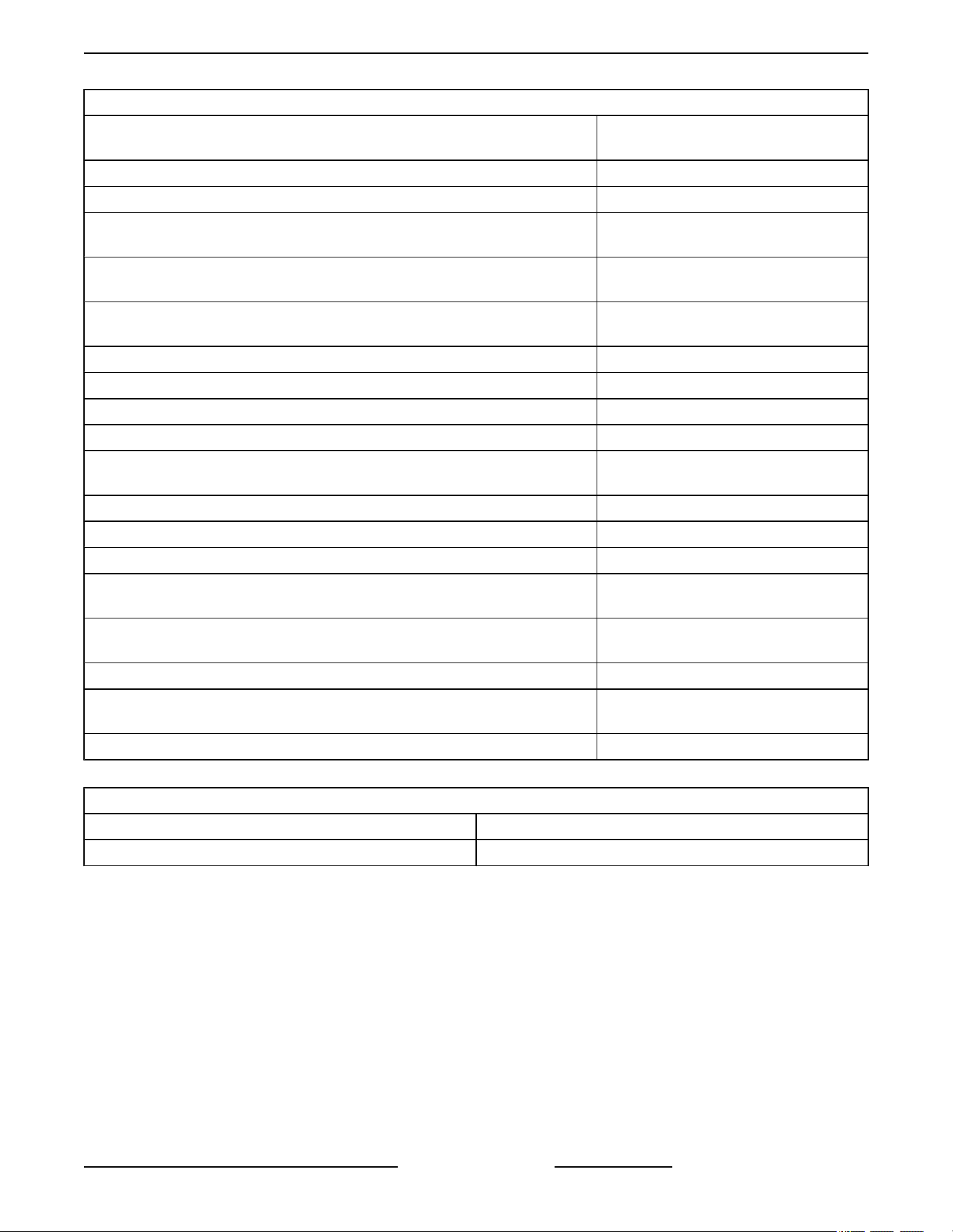
SERIAL NUMBER LOCATION
Serial number plate is attached to door of fryer.
Fig. 1
This serial number plate supplies more than the serial
number. It also contains electric requirements, gas
requirements, clearances and agency approvals. This
plate is pop riveted to the door and should not be
removed.
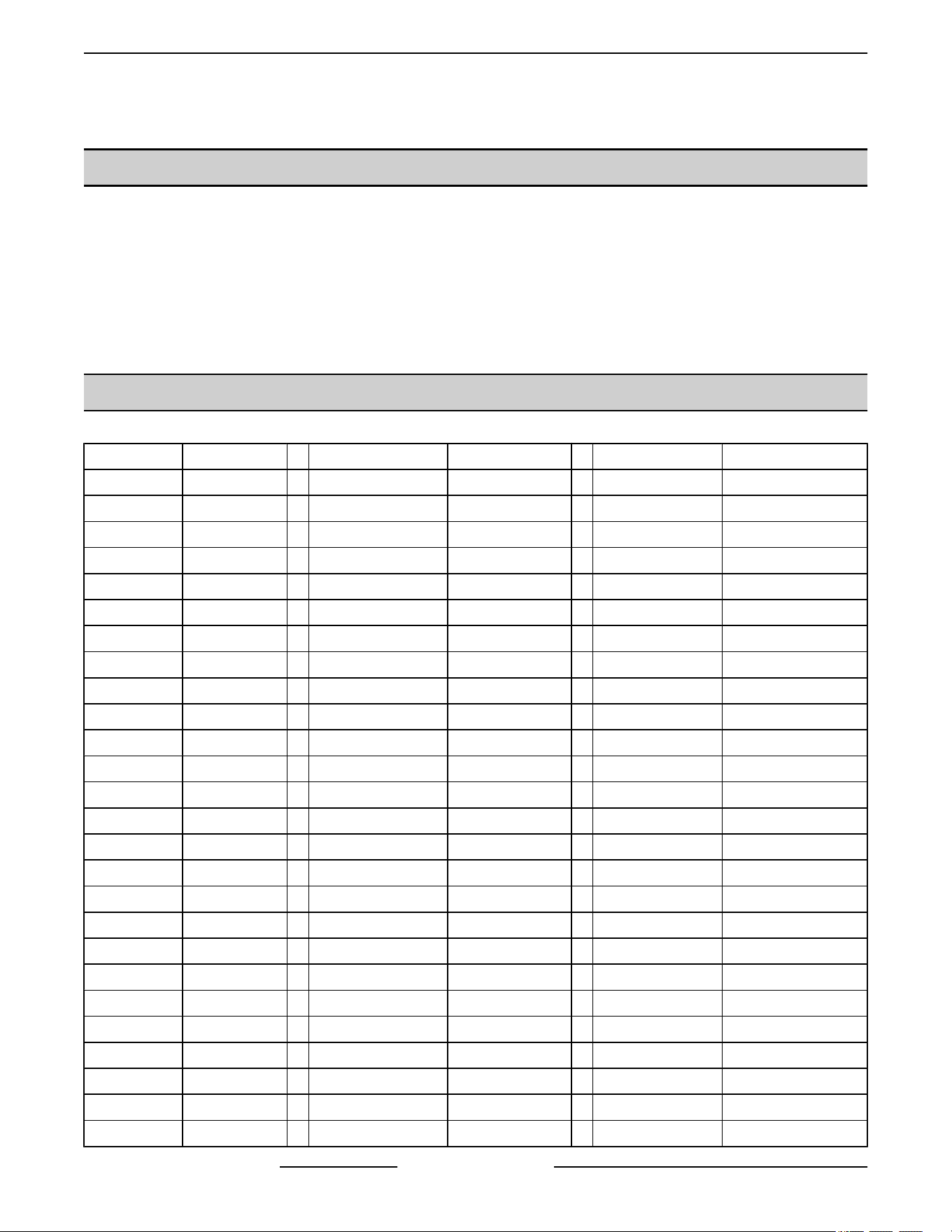
CONTROL PANELS
ANALOG CONTROL
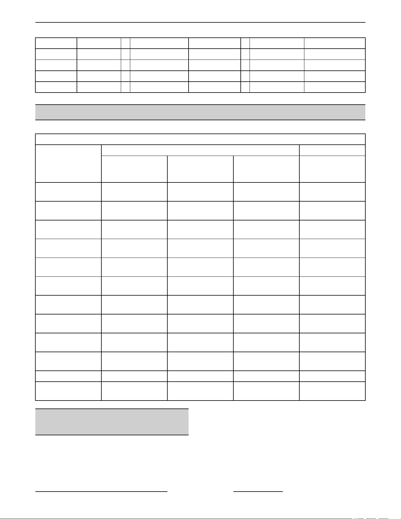
SOLID STATE CONTROL
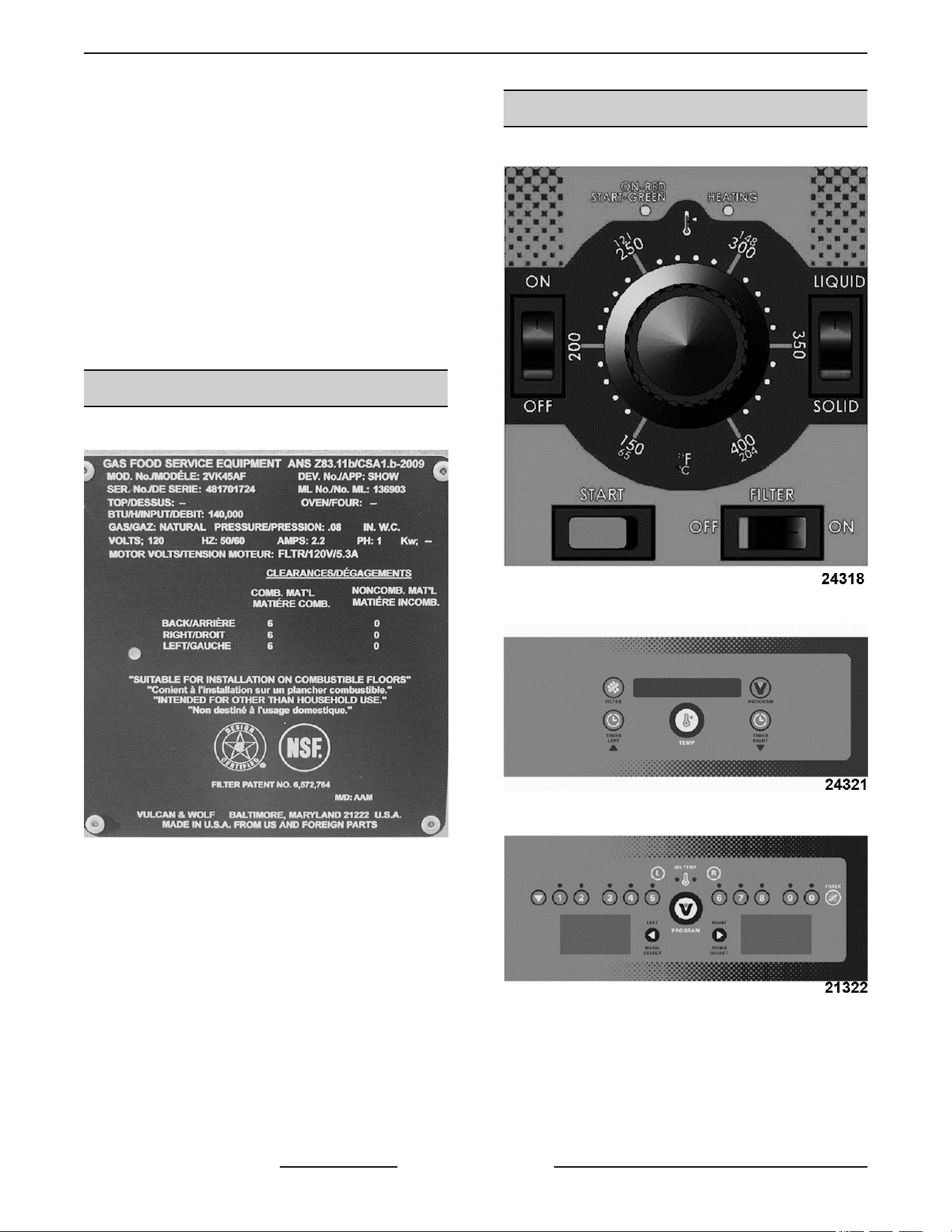
COMPUTER CONTROL
VK and TR GAS FRYERS W/Wo KleenScreen PLUS - GENERAL
F45474 Rev. D (0822) Page 8 of 64
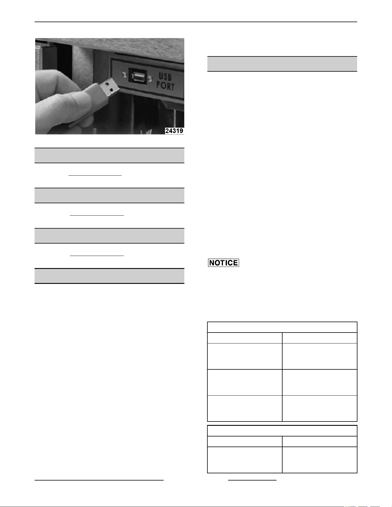
USB Port
INSTALLATION
Refer to the Instruction Manual for detailed installation
instructions.
OPERATION
Refer to the Instruction Manual for specific operating
instructions.
CLEANING
Refer to the Instruction Manual for specific cleaning
instructions.
TOOLS
STANDARD
• Standard set of hand tools.
• VOM with minimum of NFPA-70E CATIII 600V,
UL/CSA/TUV listed. Sensitivity of at least 20,000
ohms per volt. Meter leads must also be rated at
CAT III 600V.
SPECIAL
• Temperature tester (thermocouple type).
• Manometer.
• Combustion analyzer.
• Set of metric hex wrenches (must include a 2 mm
wrench).
• Set of jeweler's screwdrivers.
• Grounding kit.
• Burndy pin extraction tool RX2025 GE1; Newark
Electronics Catalog Number 16F6666. Used for
removing pin terminals on Burndy connectors.
• Thumb drive.
NOTE: Customer to supply program for uploading
menu items.
SPECIFICATIONS
ELECTRICAL:
• 120VAC supply.
• Filter motor/pump
• Basket lift motors
• Transformer
• 24VAC transformer
• Fryer controls
• Basket lift relays
• Filter relay
MANIFOLD GAS PRESSURES (per fryer section)
• Natural 0.08" W.C.
• Propane 0.08" W.C.
BUILDING SUPPLY PRESSURE
(RECOMMENDED)
• Natural 7-9" W.C.
• Propane 11" W.C.
Building supply pressure max ½ psi. (14" W.C.)
A separate high pressure step-down gas regulator
(not supplied with unit) must be used for pressures
exceeding maximum. On fryers built between 12/1/12
thru 4/7/16 have an incoming gas pressure regulator
is installed on the fryer that has a max supply pressure
rating of ½ PSI (14" W.C.).
VK INPUT BTU RATING
VK SERIES BTU/HR/SECTION
VK45A, VK45AF, VK45D,
VK45DF, VK45C,
VK45CF
70,000
VK65A, VK65AF, VK65D,
VK65DF, VK65C,
VK65CF
80,000
VK85A, VK85AF, VK85D,
VK85DF, VK85C,
VK85CF
90,000
TR INPUT BTU RATING
TR SERIES BTU/HR/SECTION
TR45A, TR45AF, TR45D,
TR45DF, TR45C,
TR45CF
70,000
VK and TR GAS FRYERS W/Wo KleenScreen PLUS - GENERAL
Page 9 of 64 F45474 Rev. D (0822)

TR INPUT BTU RATING
TR SERIES BTU/HR/SECTION
TR65A, TR65AF, TR65D,
TR65DF, TR65C,
TR65CF
80,000
TR85A, TR85AF, TR85D,
TR85DF, TR85C,
VK85CF
90,000
VK and TR GAS FRYERS W/Wo KleenScreen PLUS - GENERAL
F45474 Rev. D (0822) Page 10 of 64
REMOVAL AND REPLACEMENT OF PARTS
COVERS AND PANELS
Disconnect the electrical power to
the machine and follow lockout /
tagout procedures.
Shut off the gas before servicing the
unit and follow lockout / tagout
procedures.
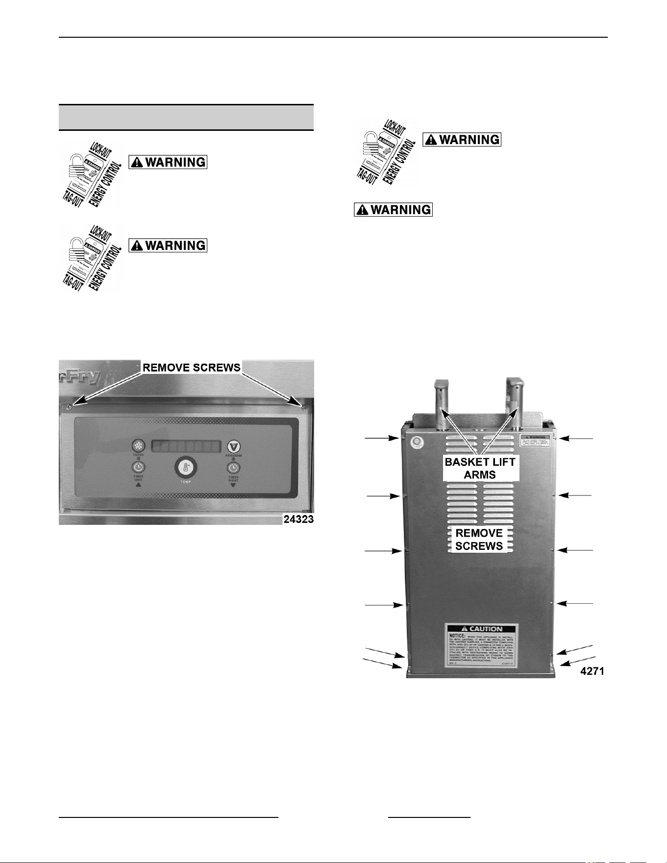
Control Panel (Solid State and Computer)
1. Remove screws at top of control panel and rotate
panel downwards.
Fig. 6
2. Disconnect wiring harness then lift panel off.
NOTE: The cooking control, control box, interface
board and wiring harness are now accessible.
3. Reverse procedure to install.
Basket Lift Covers
Shut off the gas before servicing the
unit and follow lockout / tagout
procedures.
All gas joints disturbed during servicing must be
checked for leaks. Check with a soap and water
solution (bubbles). Do not use an open flame.
NOTE: This procedure applies to fryers with
automatic basket lift option only.
1. Remove basket assembly lift arms from support
rods.
2. Remove screws securing upper cover to flue
wrap.
Fig. 7
A. Lift upper cover over support rods and place
cover to the side.
3. Remove screws securing lower cover to motor
mounting base.
VK and TR GAS FRYERS W/Wo KleenScreen PLUS - REMOVAL AND REPLACEMENT OF PARTS
Page 11 of 64 F45474 Rev. D (0822)
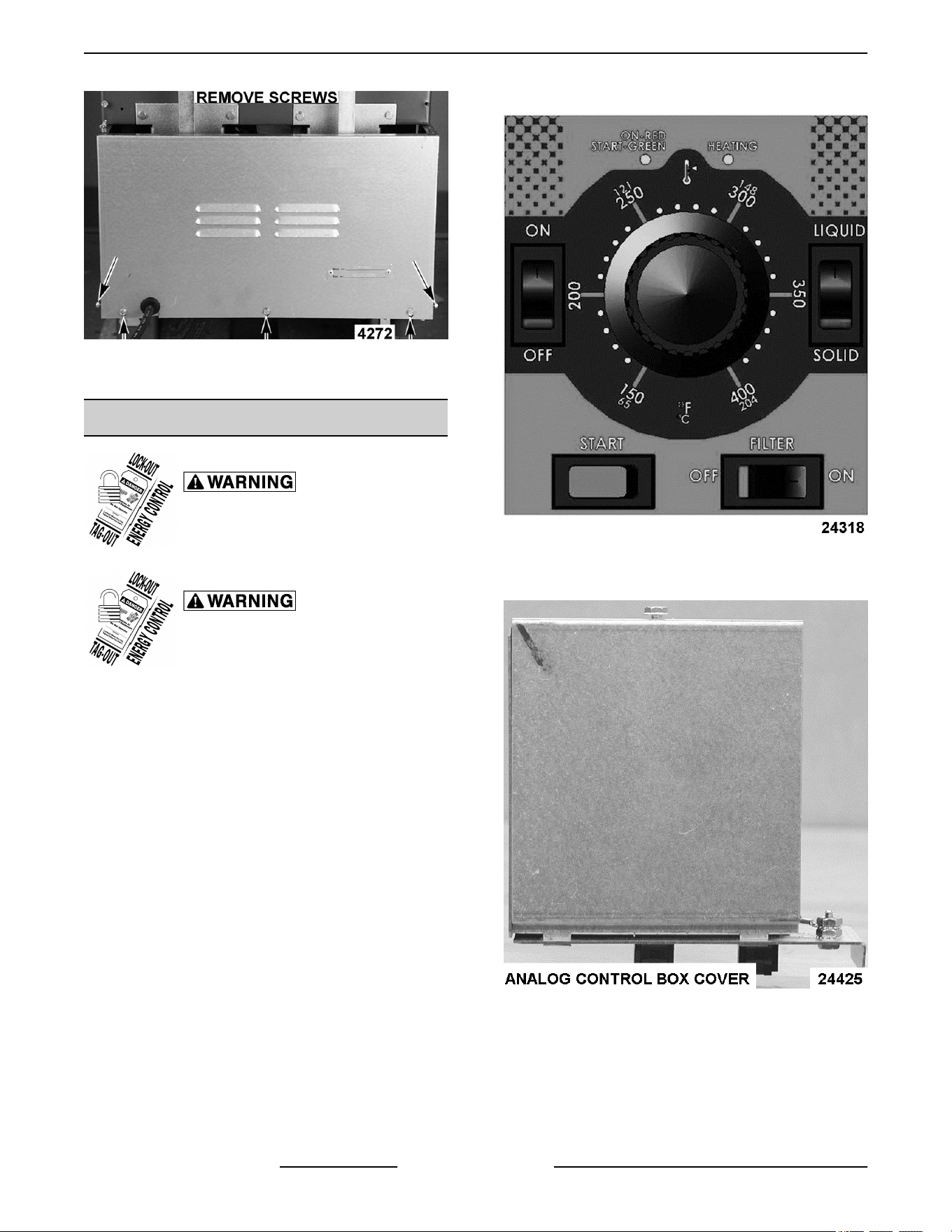
Fig. 8
4. Reverse procedure to install.
ANALOG CONTROL
Disconnect the electrical power to
the machine and follow lockout /
tagout procedures.
Shut off the gas before servicing the
unit and follow lockout / tagout
procedures.
1. Open the door.
2. Unplug wiring harnesses from bottom of control
box.
3. Remove control box from frame of fryer.
4. Loosen set screw in control knob and remove
from shaft.
Fig. 9
5. Remove control box cover.
Fig. 10
6. Disconnect lead wires as necessary to remove
control.
VK and TR GAS FRYERS W/Wo KleenScreen PLUS - REMOVAL AND REPLACEMENT OF PARTS
F45474 Rev. D (0822) Page 12 of 64
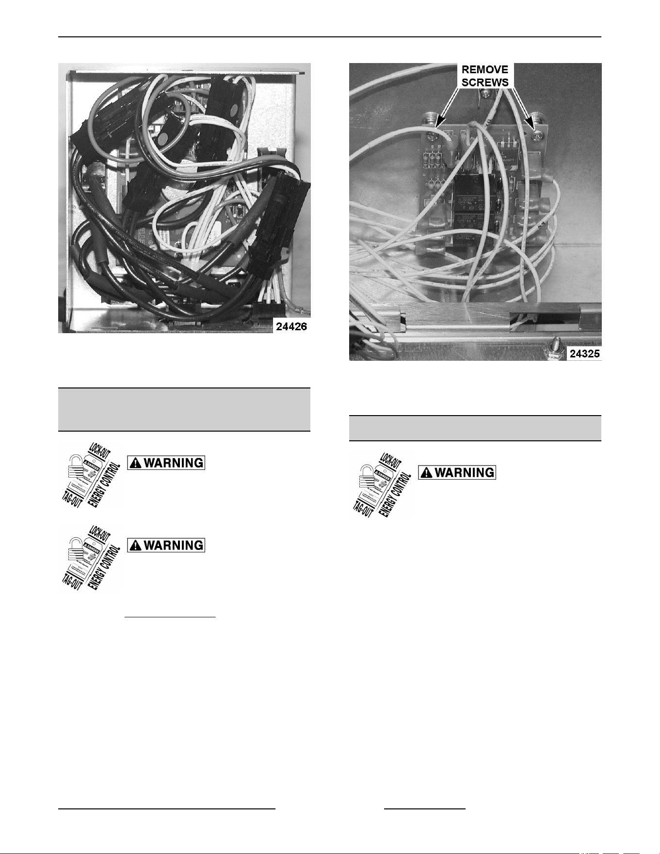
Fig. 11
7. Remove screws from front of control panel and
remove control.
INTERFACE CONTROL - D and C
SERIES
Disconnect the electrical power to
the machine and follow lockout /
tagout procedures.
Shut off the gas before servicing the
unit and follow lockout / tagout
procedures.
1. Remove CONTROL PANEL.
2. Note lead wire locations and remove wiring.
3. Remove screws securing control to fryer and
remove.
Fig. 12
4. Reverse procedure to install and check for proper
operation.
POWER SWITCH - D and C SERIES
Disconnect the electrical power to
the machine and follow lockout /
tagout procedures.
NOTE: This procedure is for solid state and computer
controls. Power switch for analog controls is part of the
analog control box.
1. Open fryer door to access power switch.
VK and TR GAS FRYERS W/Wo KleenScreen PLUS - REMOVAL AND REPLACEMENT OF PARTS
Page 13 of 64 F45474 Rev. D (0822)
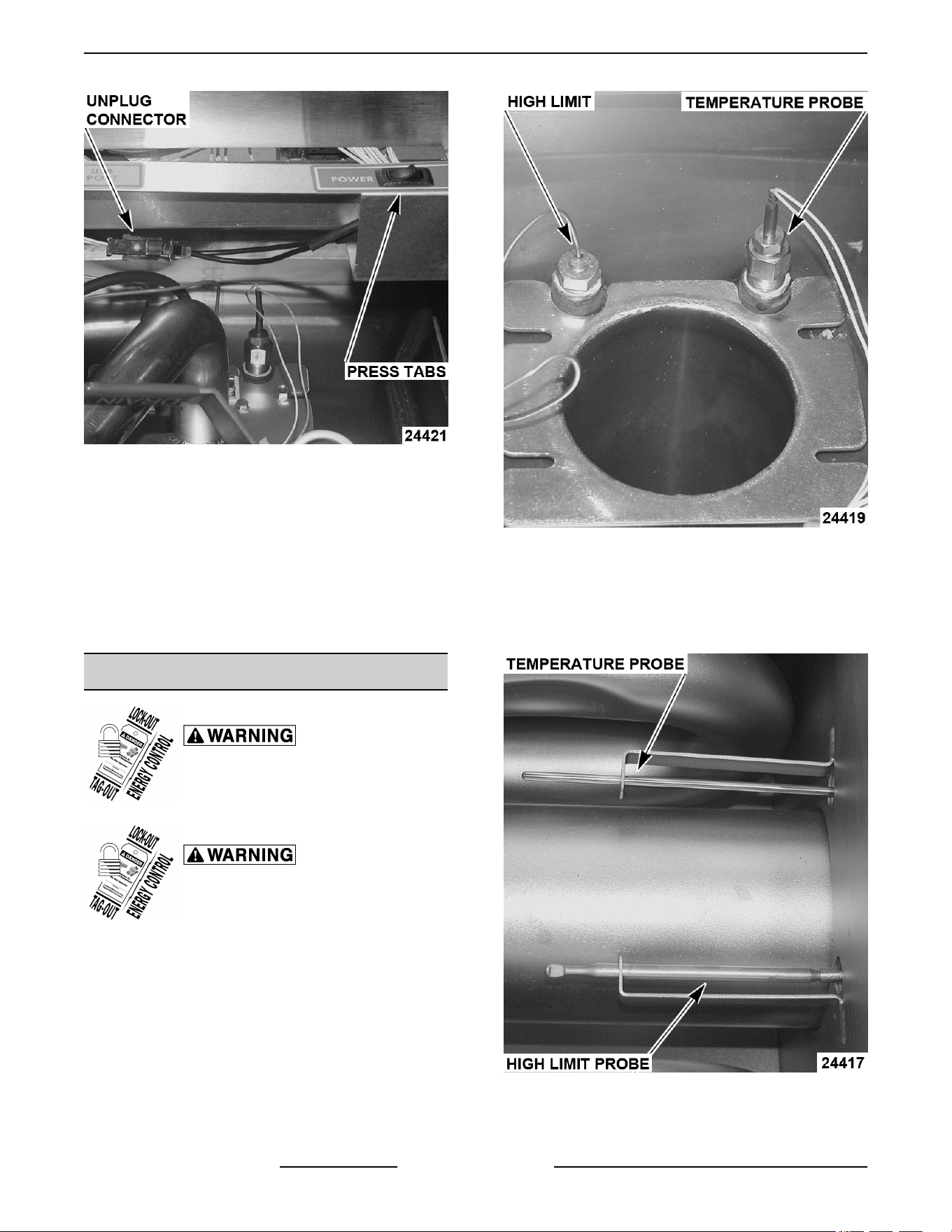
Fig. 13
2. Unplug power switch connector.
3. Reach behind power switch and press tabs on
both sides of power switch to remove switch.
NOTE: Power switch is removed from front of the
panel.
4. Reverse procedure to install new power switch.
5. Check operation of machine.
TEMPERATURE PROBE
Disconnect the electrical power to
the machine and follow lockout /
tagout procedures.
Shut off the gas before servicing the
unit and follow lockout / tagout
procedures.
1. Drain shortening from fryer tank.
2. Unplug temperature probe lead wire connector.
Fig. 14
NOTE: This picture shows the probes with the burner
removed.
3. Loosen compression nut and remove probe from
fryer.
Fig. 15
4. Install new probe making sure that probe is
installed into bracket shown.
VK and TR GAS FRYERS W/Wo KleenScreen PLUS - REMOVAL AND REPLACEMENT OF PARTS
F45474 Rev. D (0822) Page 14 of 64
HIGH LIMIT THERMOSTAT
Disconnect the electrical power to
the machine and follow lockout /
tagout procedures.
Shut off the gas before servicing the
unit and follow lockout / tagout
procedures.
Do not sharply bend or kink the high limit capillary tube
or damage may occur.
NOTE: Units manufactured before 8/10/17 will utilize
the Robertshaw capillary wire with probe type. Units
manufactured beginning 8/10/17 will use a Fenwal
cartridge type high limit with no capillary.
1. Drain shortening from fryer tank.
2. Disconnect lead wires from high limit thermostat.
3. Remove screws securing high limit to mounting
bracket.
Fig. 16
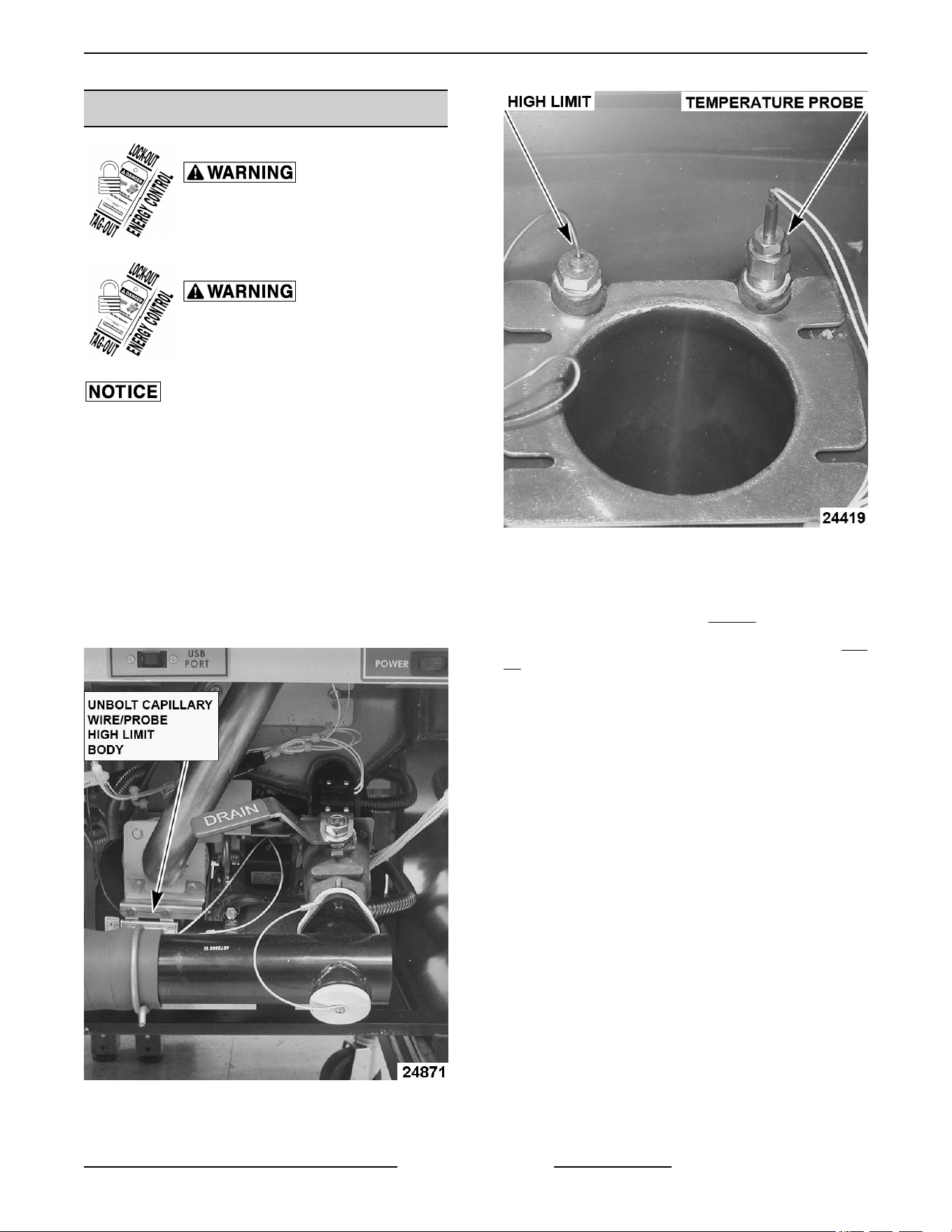
4. Remove the capillary tube retaining and packing
nuts.
Fig. 17
NOTE: This picture shows the probes with the burner
removed.
5. Slide high limit probe (1, Fig. 18) out of fry tank.
NOTE: High limit no capillary wire type shown in Fig.
18.
VK and TR GAS FRYERS W/Wo KleenScreen PLUS - REMOVAL AND REPLACEMENT OF PARTS
Page 15 of 64 F45474 Rev. D (0822)
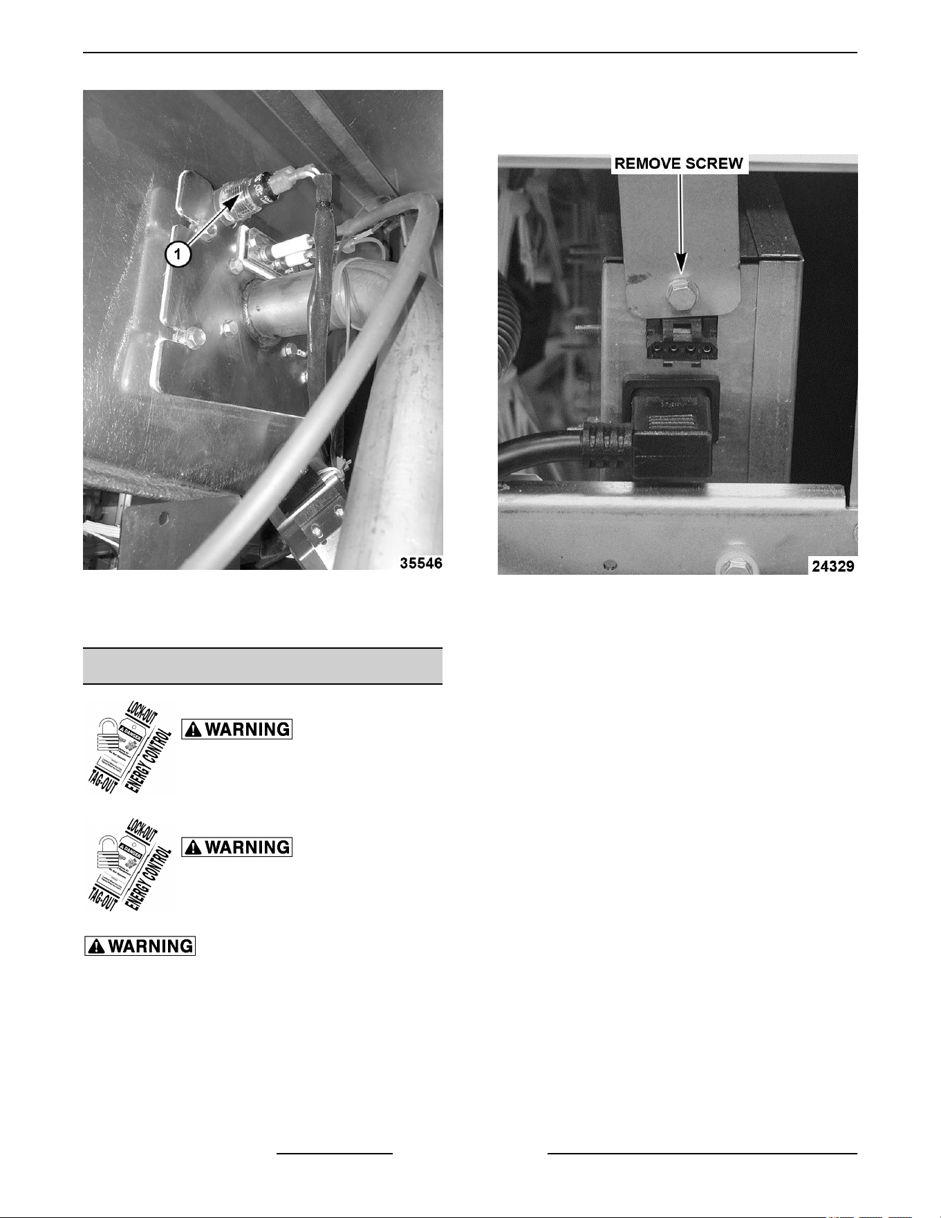
Fig. 18
6. Reverse procedure to install and check for proper
operation.
POWER SUPPLY BOX
Disconnect the electrical power to
the machine and follow lockout /
tagout procedures.
Shut off the gas before servicing the
unit and follow lockout / tagout
procedures.
All gas joints disturbed during servicing must be
checked for leaks. Check with a soap and water
solution (bubbles). Do not use an open flame.
NOTE: The power supply box must be removed to
access the following components: ignition module, all
24 volt relays, blower control board, both time delay
timers, 120 volt transformer.
1. Access rear of fryer and remove screw holding
power supply box to support bracket. The box will
lower to clear bracket.
Fig. 19
2. Access front of fryer to slide power supply box
toward rear of fryer to disconnect from front
support bracket.
VK and TR GAS FRYERS W/Wo KleenScreen PLUS - REMOVAL AND REPLACEMENT OF PARTS
F45474 Rev. D (0822) Page 16 of 64
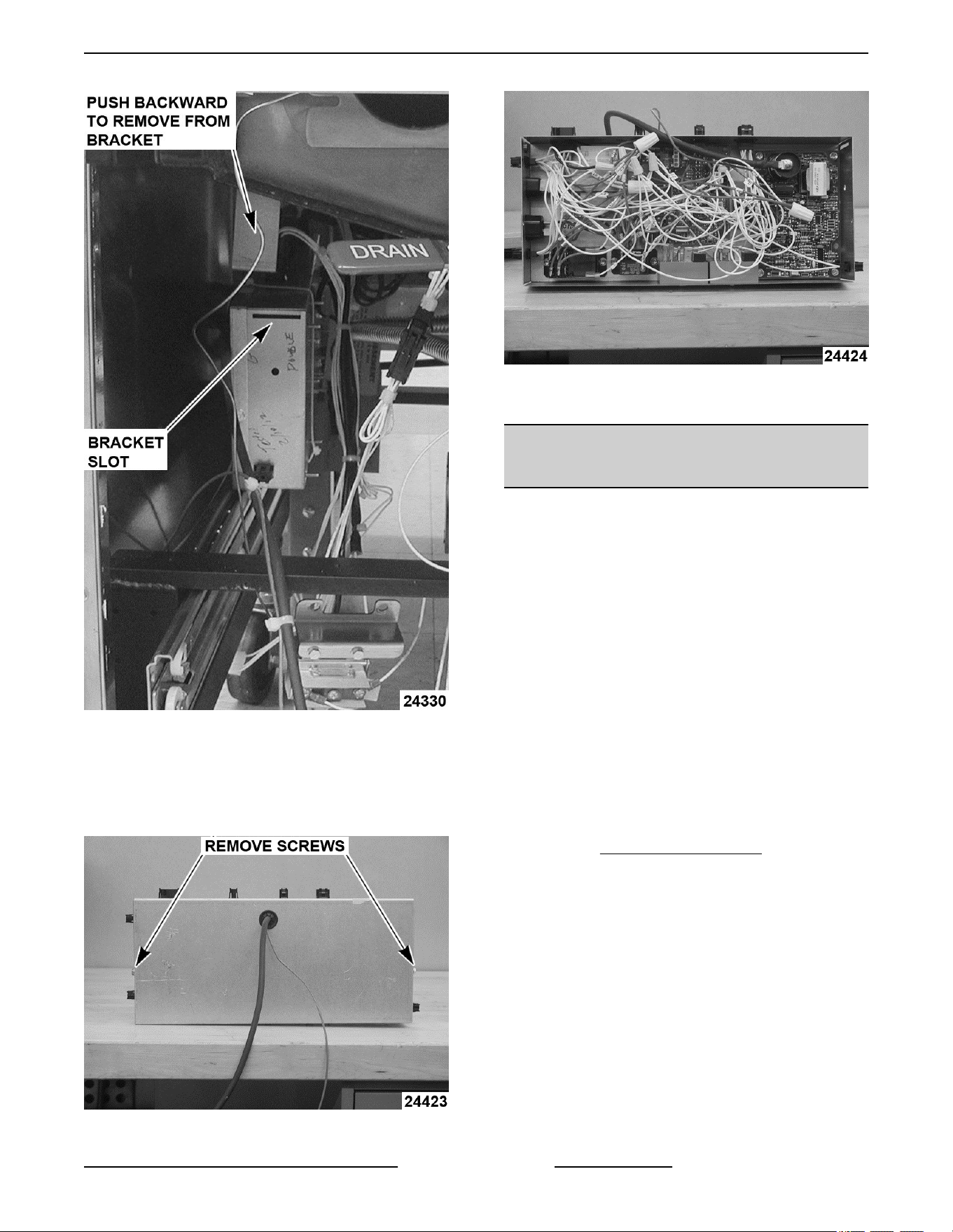
Fig. 20
3. Unplug all connecters from power supply box and
remove box from under fryer.
4. Remove cover to access power supply box
components.
Fig. 21
Fig. 22
5. Reverse procedure to install.
POWER SUPPLY BOX
COMPONENTS BEFORE 12/1/12
NOTE: The ignition module, blower control board and
the time delay timers will not be available to the field
any longer. If any one of these items fail, replace
power supply box. However, the filter relays and the
transformer are still available and can be replaced in
the field.
Ignition Module
Replace with updated Power Supply Box Assembly.
Blower Control Board
Replace with updated Power Supply Box Assembly.
Time Delay Timers
Replace with updated Power Supply Box Assembly.
Blower Relay
Replace with updated Power Supply Box Assembly.
Filter Relays (24 VAC and 120 VAC)
1. Remove POWER SUPPLY BOX.
2. Note location of all wiring to the relay and remove
wiring.
3. Remove screw and remove relay from box.
VK and TR GAS FRYERS W/Wo KleenScreen PLUS - REMOVAL AND REPLACEMENT OF PARTS
Page 17 of 64 F45474 Rev. D (0822)
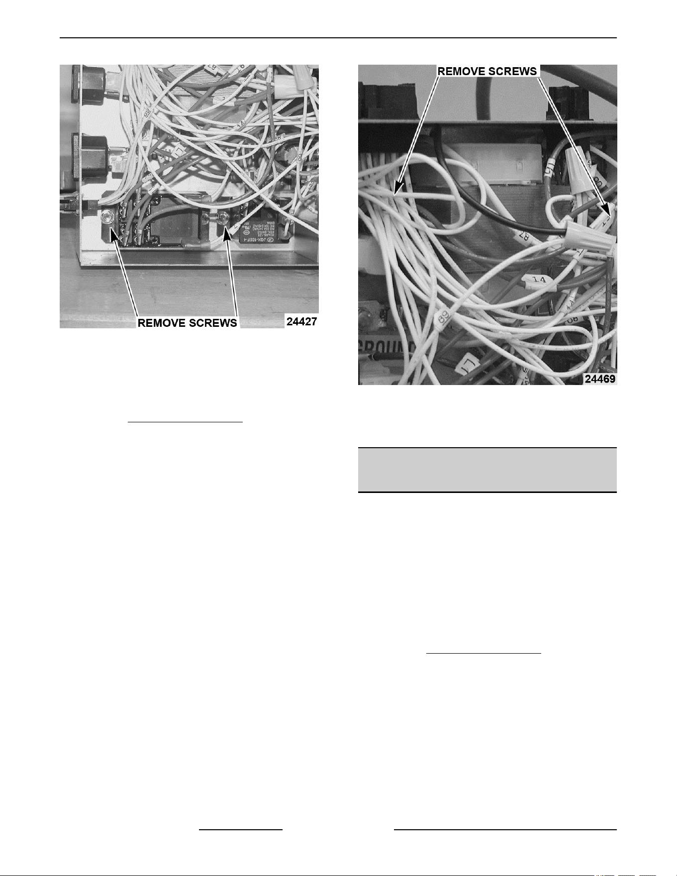
Fig. 23
4. Reverse procedure to install new relay.
5. Reinstall power supply box and check operation.
120 Volt Transformer
1. Remove POWER SUPPLY BOX.
2. Note location of wiring on 120 volt transformer
and remove wiring.
3. Remove screws and remove transformer from
the box.
Fig. 24
4. Reverse procedure to install new transformer.
5. Reinstall power supply box and check operation.
POWER SUPPLY BOX
COMPONENTS AFTER 12/1/12
NOTE: Power supply boxes built after 12/1/12 have
different components in them. The 24 volt electronic
ignition relay, blower control board, ignition module
and both time delay relays are replaced by a single
control board.
NOTE: The new ignition module will not have a
separate flame sense rod and wire. Ignition module
will rectify flame through high voltage wire.
120 Volt Transformer
1. Remove POWER SUPPLY BOX.
2. Note location of all wiring and remove wiring from
transformer.
3. Remove four screws and remove transformer
from box.
VK and TR GAS FRYERS W/Wo KleenScreen PLUS - REMOVAL AND REPLACEMENT OF PARTS
F45474 Rev. D (0822) Page 18 of 64
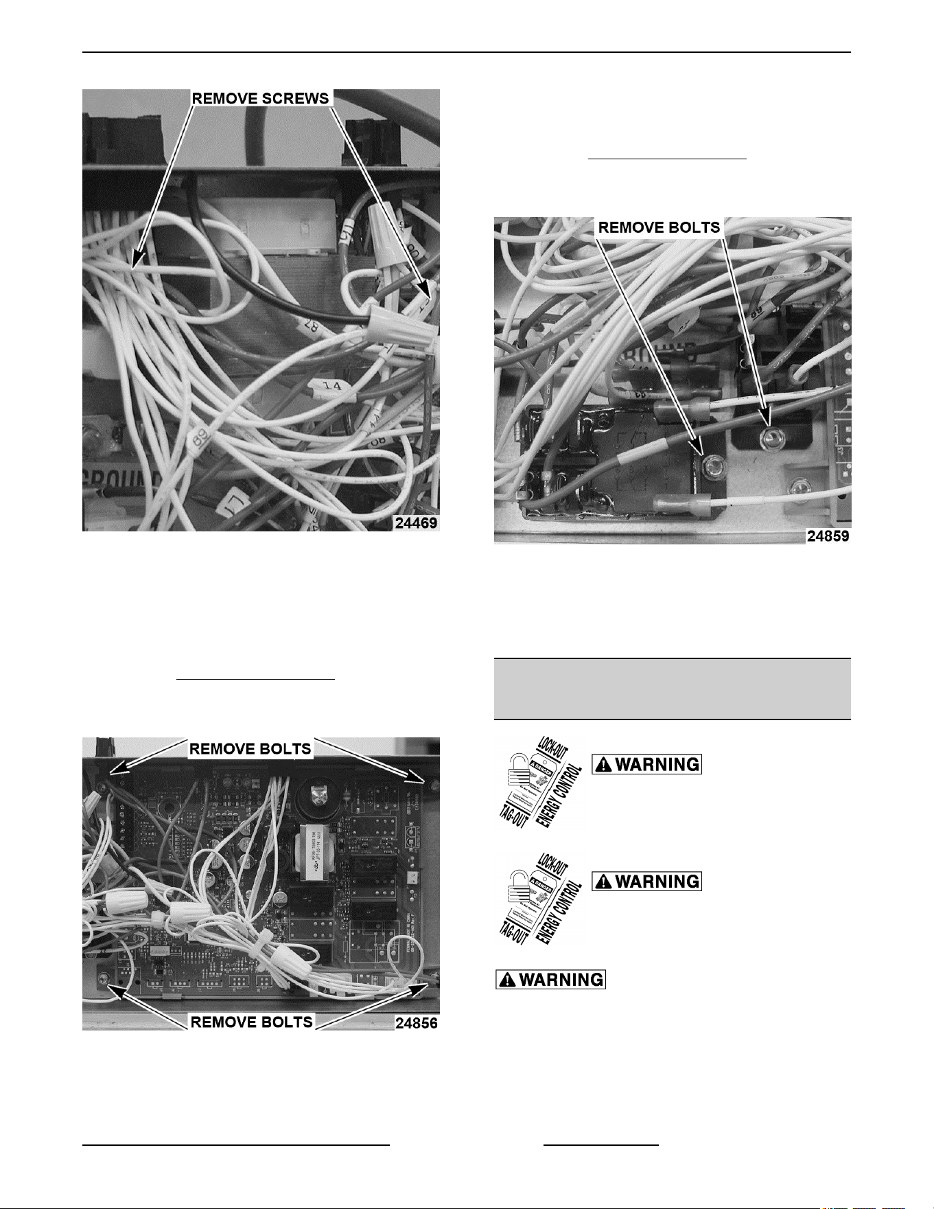
Fig. 25
4. Reverse the procedure to install new
transformer.
5. Reinstall power supply box and check operation.
Control Board
1. Remove POWER SUPPLY BOX.
2. Note location of wiring to relay control board and
remove wiring.
Fig. 26
3. Remove screws and remove from box.
4. Reverse the procedure to install new relay
control board.
5. Reinstall power supply box and check operation.
Filter Relays
1. Remove POWER SUPPLY BOX.
2. Note location of wiring to the relays and remove
wiring.
Fig. 27
3. Remove screws and remove from box.
4. Reverse the procedure to install new relays.
5. Reinstall power supply box and check operation.
BURNER & GAS VALVE
ASSEMBLY
Disconnect the electrical power to
the machine and follow lockout /
tagout procedures.
Shut off the gas before servicing the
unit and follow lockout / tagout
procedures.
All gas joints disturbed during servicing must be
checked for leaks. Check with a soap and water
solution (bubbles). Do not use an open flame.
1. Remove gas line from gas valve.
2. Remove electric plug connector from gas valve.
VK and TR GAS FRYERS W/Wo KleenScreen PLUS - REMOVAL AND REPLACEMENT OF PARTS
Page 19 of 64 F45474 Rev. D (0822)
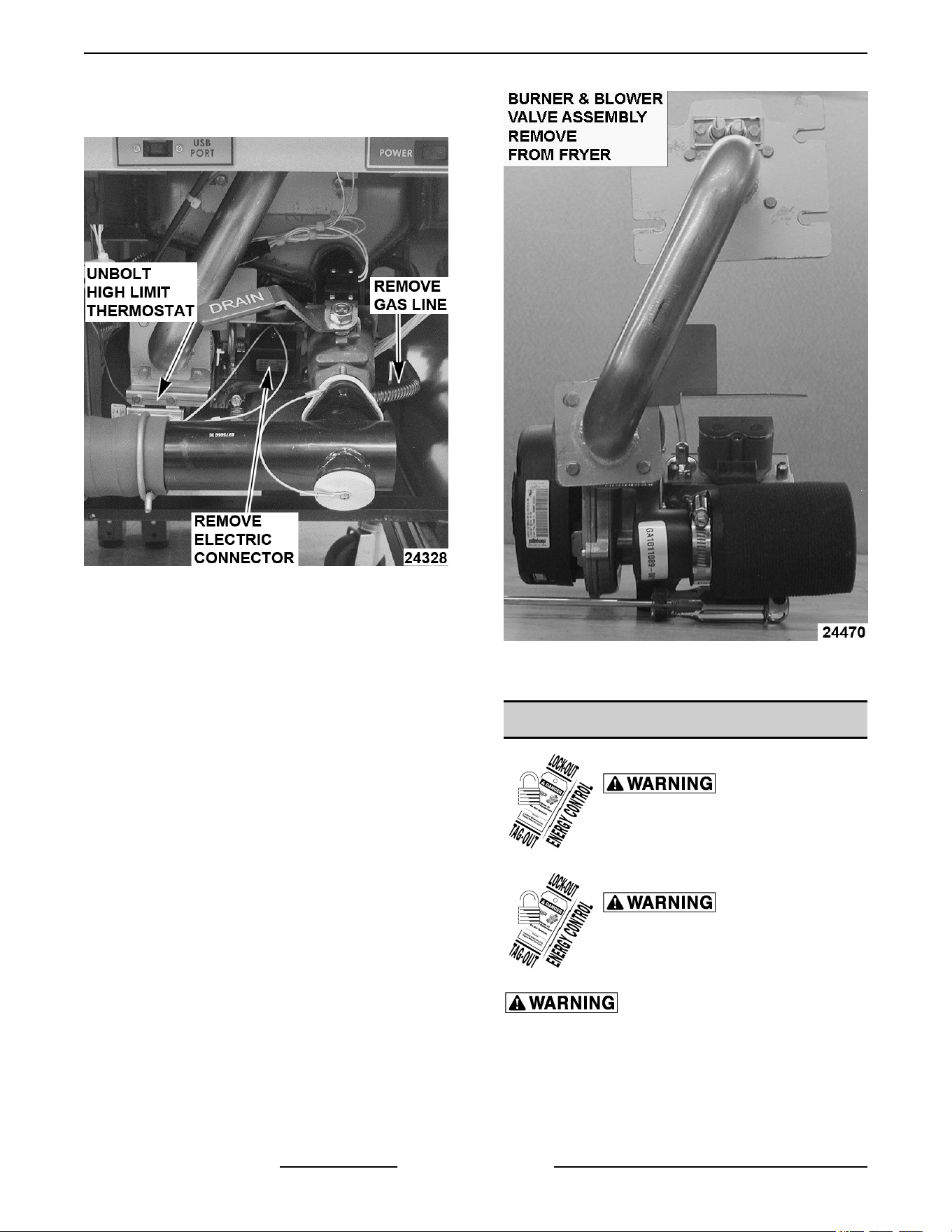
3. Unbolt high limit thermostat clamp from transfer
tube.
Fig. 28
4. Remove bolts and remove burner from fryer.
Fig. 29
5. Reverse procedure to reinstall burner.
GAS VALVE
Disconnect the electrical power to
the machine and follow lockout /
tagout procedures.
Shut off the gas before servicing the
unit and follow lockout / tagout
procedures.
All gas joints disturbed during servicing must be
checked for leaks. Check with a soap and water
solution (bubbles). Do not use an open flame.
If the gas valve fails and needs to be replaced, you
must order a complete blower/gas valve assembly.
The reason for this is every blower/gas valve
VK and TR GAS FRYERS W/Wo KleenScreen PLUS - REMOVAL AND REPLACEMENT OF PARTS
F45474 Rev. D (0822) Page 20 of 64
assembly is set up at the factory to operate at the most
efficient level possible. This set up procedure cannot
be duplicated in the field. If you feel that the gas valve
is not set up correctly or not operating correctly, call
product service and they will help solve the problem.
BASKET LIFT TUBE
Disconnect the electrical power to
the machine and follow lockout /
tagout procedures.
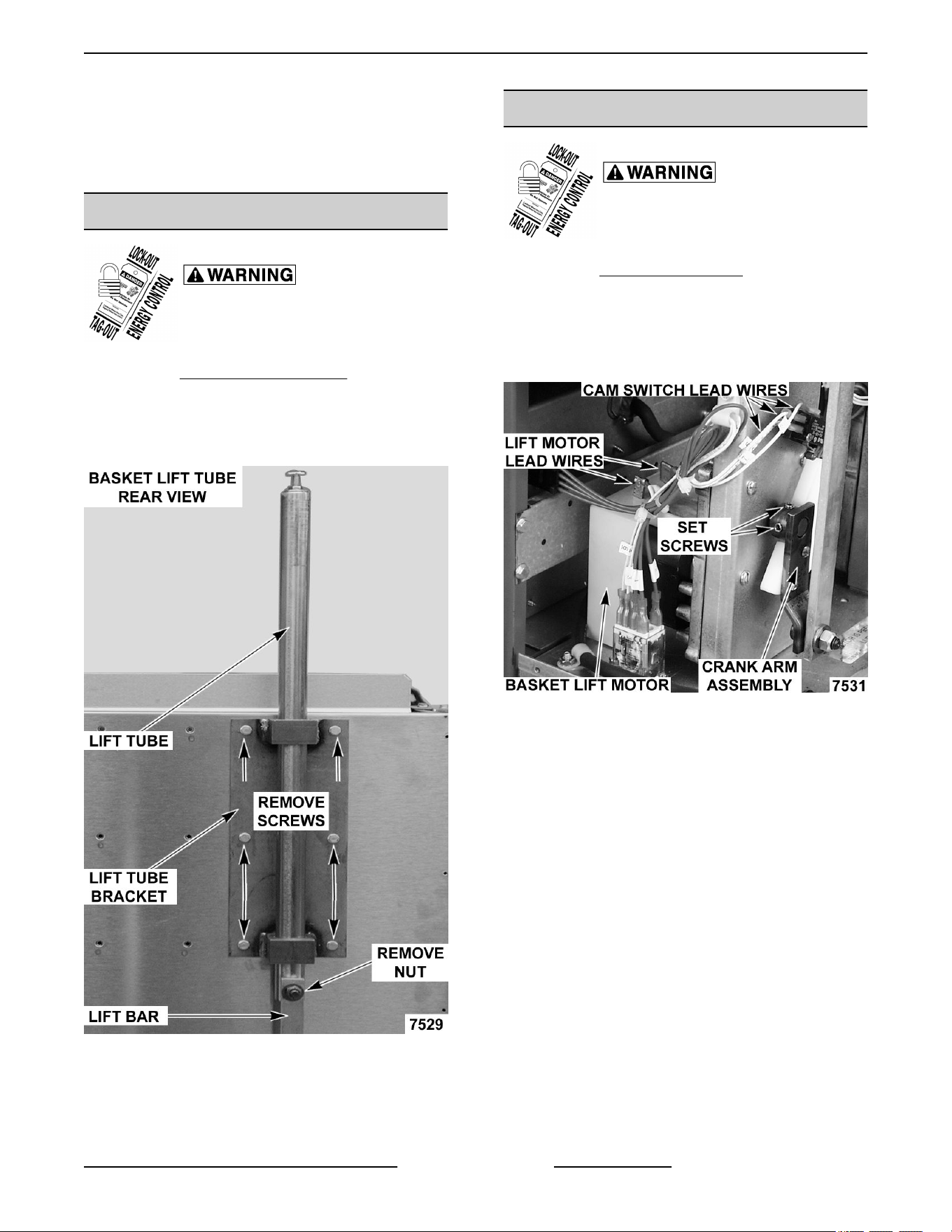
1. Remove BASKET LIFT COVERS.
2. Remove nut securing lift bar to lift tube.
3. Remove screws securing lift tube bracket to fryer
then remove bracket and lift tube.
Fig. 30
4. Reverse procedure to install.
BASKET LIFT MOTOR
Disconnect the electrical power to
the machine and follow lockout /
tagout procedures.
1. Remove BASKET LIFT TUBE.
2. Disconnect lead wires from cam switch and
basket lift motor.
3. Loosen set screws securing crank arm assembly
to basket lift motor shaft.
Fig. 31
4. Remove screws securing basket lift motor to cam
bracket, then remove motor from bracket.
VK and TR GAS FRYERS W/Wo KleenScreen PLUS - REMOVAL AND REPLACEMENT OF PARTS
Page 21 of 64 F45474 Rev. D (0822)
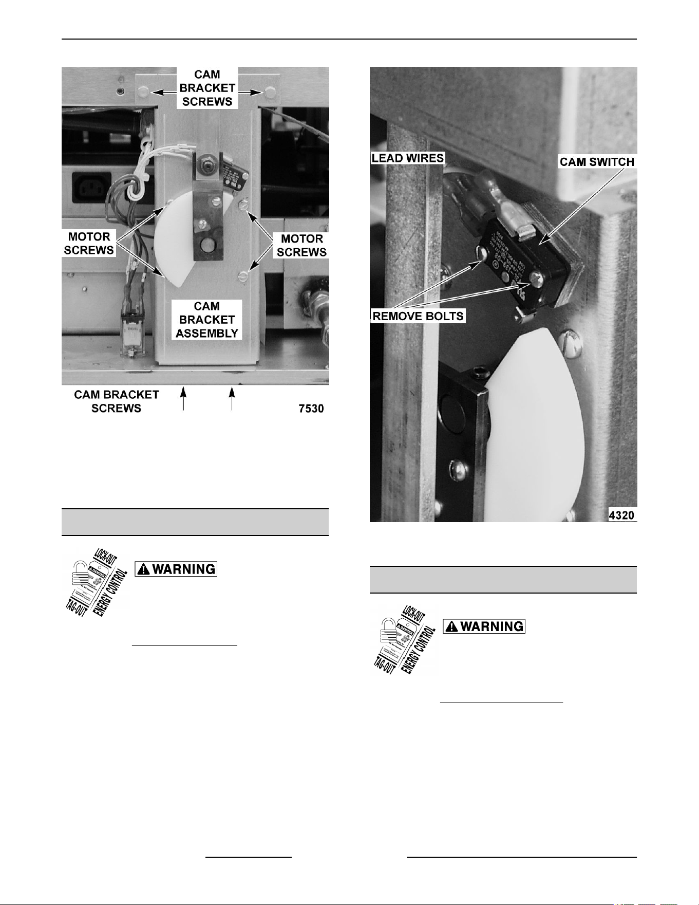
Fig. 32
5. Reverse procedure to install and check for proper
operation.
NOTE: After reinstalling motor keep all wire leads
clear from moving parts.
BASKET LIFT CAM SWITCH
Disconnect the electrical power to
the machine and follow lockout /
tagout procedures.
1. Remove BASKET LIFT TUBE.
2. Disconnect lead wires from cam switch.
3. Remove screws securing cam switch to cam
bracket.
Fig. 33
4. Reverse procedure to install.
BASKET LIFT CAM
Disconnect the electrical power to
the machine and follow lockout /
tagout procedures.
1. Remove BASKET LIFT COVERS.
2. Remove nut securing lift bar to cam assembly.
3. Loosen cam set screw.
4. Remove screws securing cam to the crank arm
assembly.
VK and TR GAS FRYERS W/Wo KleenScreen PLUS - REMOVAL AND REPLACEMENT OF PARTS
F45474 Rev. D (0822) Page 22 of 64
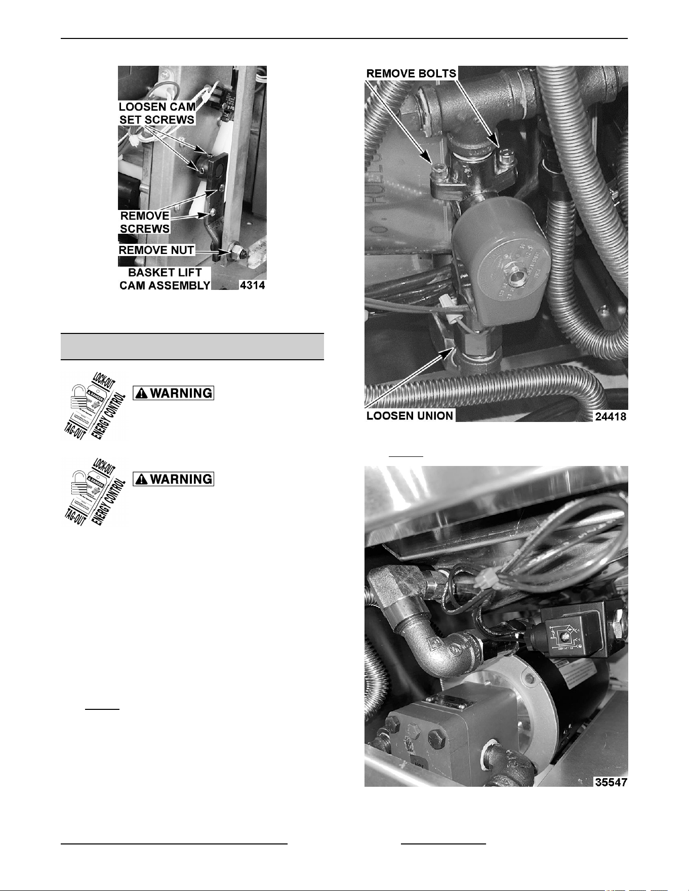
Fig. 34
5. Reverse procedure to install.
FILL SOLENOID VALVE (KSP)
Disconnect the electrical power to
the machine and follow lockout /
tagout procedures.
Shut off the gas before servicing the
unit and follow lockout / tagout
procedures.
NOTE: Units manufactured before 6/8/14 will utilize
the Jefferson Brand with rounded solenoid cover.
Units manufactured beginning 6/18/14 will use the
Bacarra Brand with a square solenoid cover.
1. Remove filter tank from fryer.
2. Access fill solenoid valve.
3. Loosen union at rear of valve,
4. Remove bolts securing valve and remove valve
from the fryer.
Fig. 35 JEFFERSON BRAND SHOWN
Fig. 35
Fig. 36 BACCARRA BRAND SHOWN
Fig. 36
5. Reverse procedure to reinstall valve.
VK and TR GAS FRYERS W/Wo KleenScreen PLUS - REMOVAL AND REPLACEMENT OF PARTS
Page 23 of 64 F45474 Rev. D (0822)
FILTER HOSE SWITCH (KSP)
Disconnect the electrical power to
the machine and follow lockout /
tagout procedures.
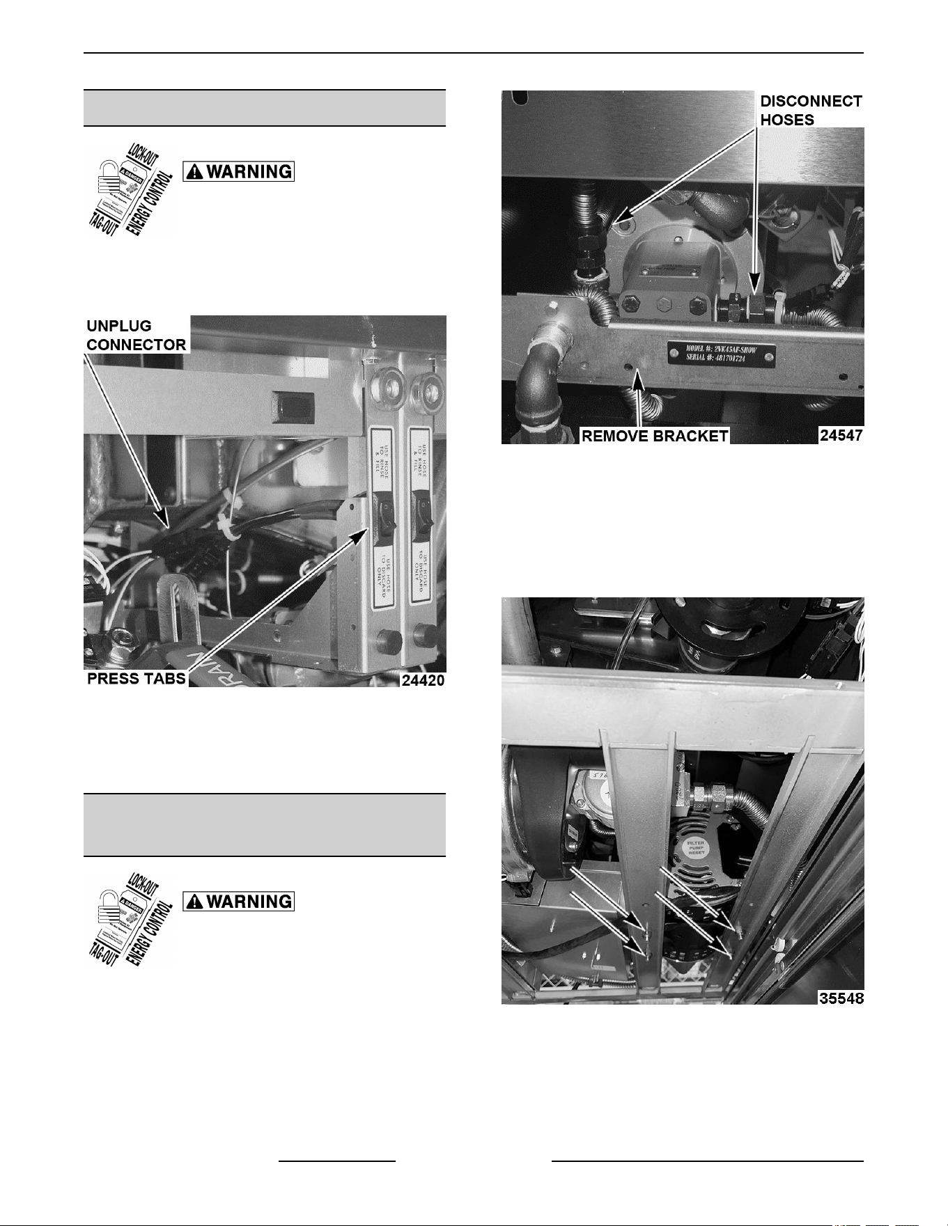
1. Open fryer door to access filter hose switch.
2. Unplug lead wire connections.
Fig. 37
3. Press tabs on rear of switch and push out front of
fry cabinet.
4. Reverse procedure to install new switch.
FILTER PUMP AND MOTOR
(KLEENSCREEN FRYERS ONLY)
Disconnect the electrical power to
the machine and follow lockout /
tagout procedures.
1. Access rear of fryer.
2. Remove four bolts holding rear cross bracket,
and carefully lower bracket.
3. Disconnect both hoses from filter pump.
Fig. 38
4. Disconnect electric connections to filter pump
motor.
5. Remove filter drain pan.
6. Remove splash guard fasteners and lower to
access pump mounting bolts.
Fig. 39
7. Unbolt filter pump motor from fryer frame.
8. Carefully remove filter pump assembly through
rear of fryer.
VK and TR GAS FRYERS W/Wo KleenScreen PLUS - REMOVAL AND REPLACEMENT OF PARTS
F45474 Rev. D (0822) Page 24 of 64
9. Reverse procedure to reinstall filter pump
assembly.
DRAIN VALVE INTERLOCK
SWITCH (DVI)
Disconnect the electrical power to
the machine and follow lockout /
tagout procedures.
Shut off the gas before servicing the
unit and follow lockout / tagout
procedures.
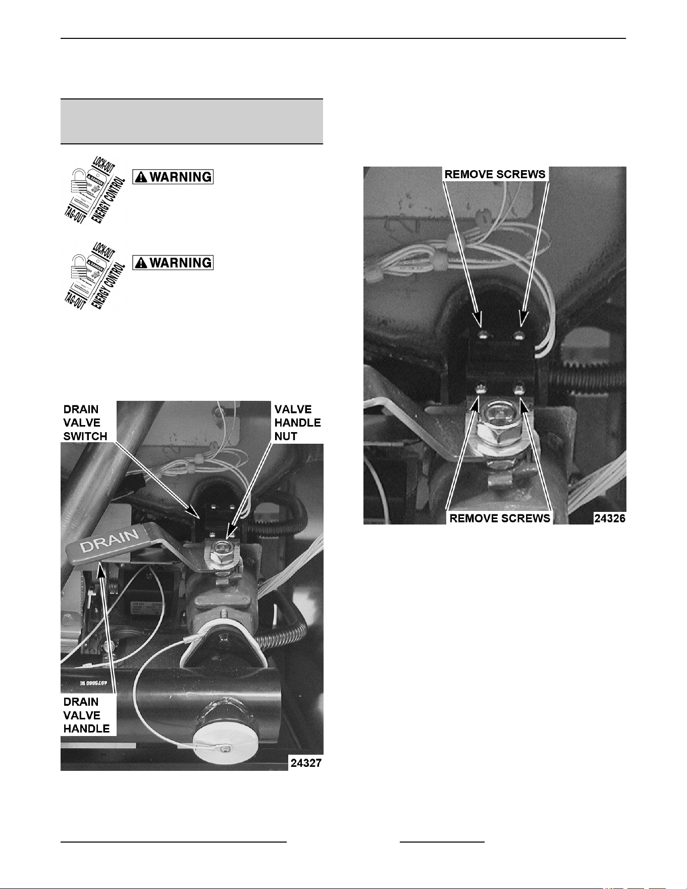
1. Open fryer section door.
2. Locate drain valve switch
3. Remove nut holding drain valve handle and
remove handle.
Fig. 40
NOTE: Make sure drain handle is in closed position.
If fry tank is full of shortening, carefully remove drain
handle. Do not turn handle to open position. Doing so
will allow shortening to drain on floor.
4. Remove drain valve interlock switch bracket from
valve.
5. Remove screws holding the drain valve interlock
switch on bracket and take switch from bracket.
Fig. 41
6. Unplug drain valve interlock switch from wiring
harness and remove switch from fryer.
7. Reverse procedure to install and check for proper
operation.
VK and TR GAS FRYERS W/Wo KleenScreen PLUS - REMOVAL AND REPLACEMENT OF PARTS
Page 25 of 64 F45474 Rev. D (0822)
FRY TANK
Disconnect the electrical power to
the machine and follow lockout /
tagout procedures.
Shut off the gas before servicing the
unit and follow lockout / tagout
procedures.
All gas joints disturbed during servicing must be
checked for leaks. Check with a soap and water
solution (bubbles). Do not use an open flame.
1. Remove BURNER ASSEMBLY.
2. Remove both HIGH LIMIT THERMOSTAT and
TEMPERATURE [ROBE.
3. Remove DRAIN VALVE INTERLOCK SWITCH.
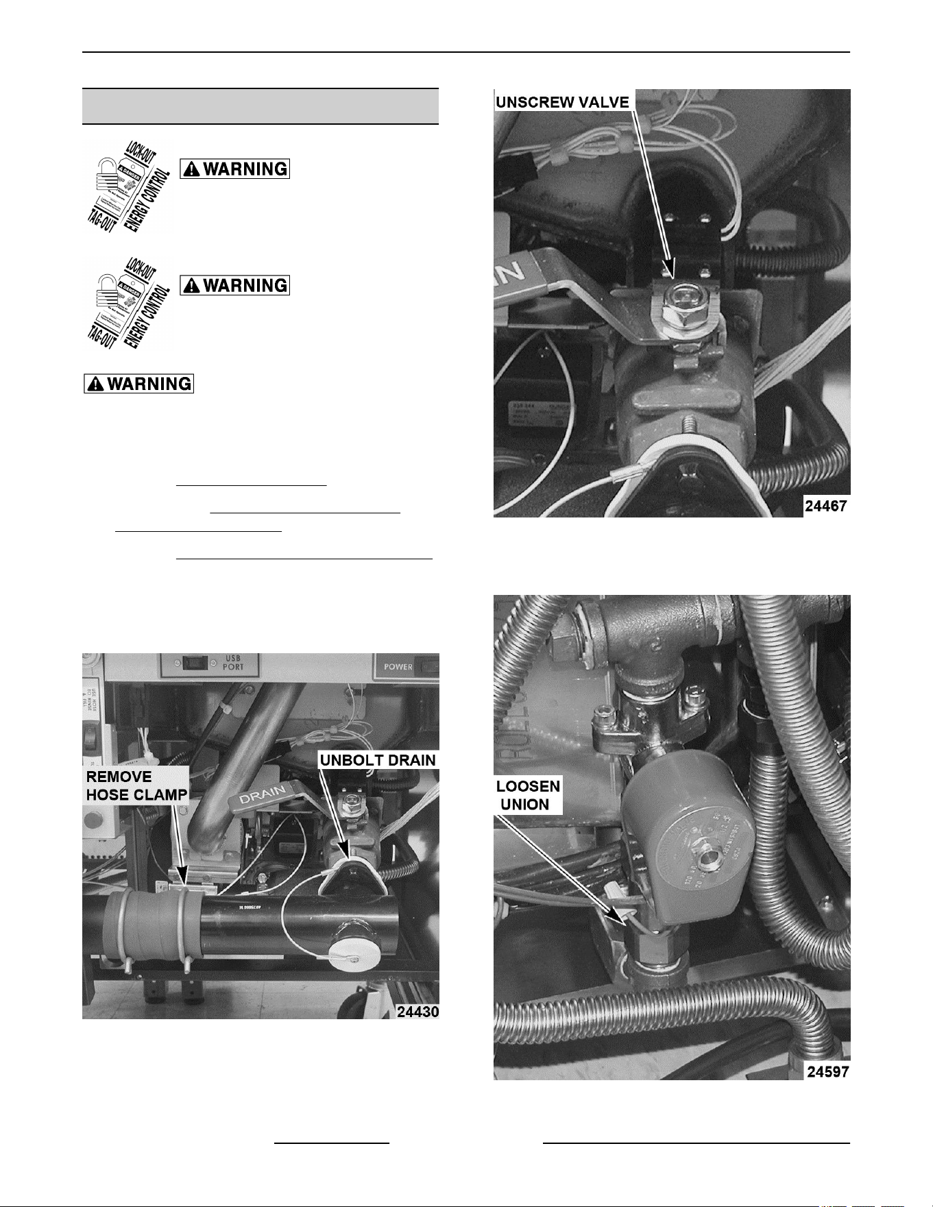
4. Remove drain assembly from drain valve.
A. Remove hose clamp from rubber boot.
B. Remove drain piping from drain valve.
Fig. 42
5. Remove drain valve from fry tank.
Fig. 43
6. Loosen and disconnect the oil return line, if
equipped with filter system.
Fig. 44
VK and TR GAS FRYERS W/Wo KleenScreen PLUS - REMOVAL AND REPLACEMENT OF PARTS
F45474 Rev. D (0822) Page 26 of 64
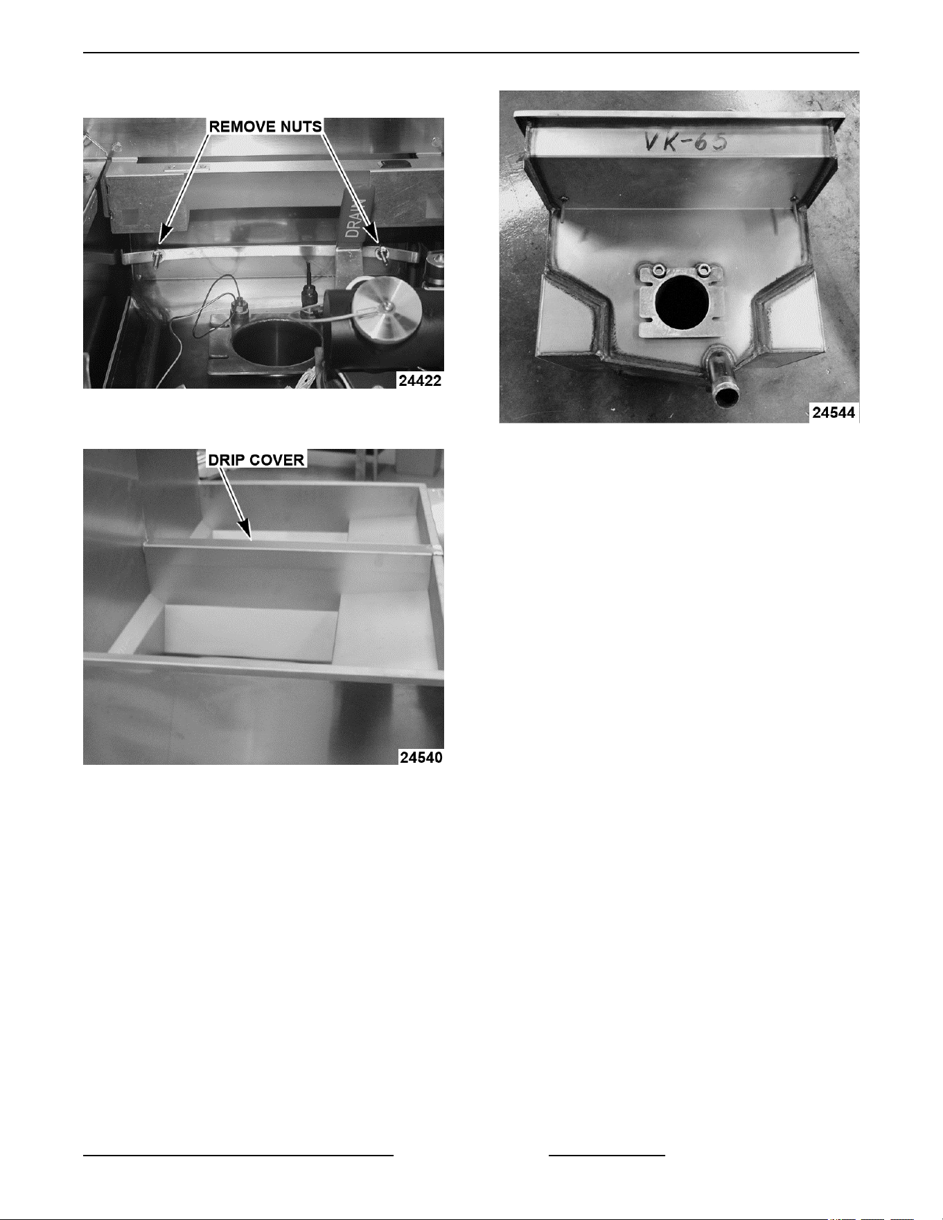
7. Remove fry tank bolt down bracket.
Fig. 45
8. Remove fry tank cover plate.
Fig. 46
A. Cover plate is glued to tank and will have to
be pried off.
B. Order a replacement plate prior to replacing
fry tank.
9. If basket lifts are installed, they will have to be
removed from rear of tank.
10. Remove tank from fryer.
Fig. 47
11. Reverse order of this procedure to install new fry
tank.
VK and TR GAS FRYERS W/Wo KleenScreen PLUS - REMOVAL AND REPLACEMENT OF PARTS
Page 27 of 64 F45474 Rev. D (0822)
SERVICE PROCEDURES AND ADJUSTMENTS
Certain procedures in this section require electrical test or measurements while power is
applied to the machine. Exercise extreme caution at all times and follow Arc Flash procedures.
If test points are not easily accessible, disconnect power and follow Lockout/Tagout
procedures, attach test equipment and reapply power to test.
ELECTRIC CONNECTIONS
The VK series fryers are supplied with a 120Volt cord
and three prong plug. If local electrical codes require
that these fryers be plugged into a Ground Fault
Interrupter or GFI. You must use GFI part number
913053. Other GFI outlets may not have the correct
tolerance for the spark to ground ignition system
employed with the VK series fryers.
HARMONIC TONE
Harmonic Tone (hum) at First Start
At first start, fryer will begin heating in low fire. There
will be a harmonic tone that is NORMAL to hear. As
fryer continues to heat, harmonic tone will dissipate
and become less noticeable. When fryer reaches
135°F (end of melt cycle), fryer will heat on high fire
and blower speed will increase.
TEMPERATURE PROBE FAULT
CODES
Certain procedures in this section
require electrical test or
measurements while power is
applied to the machine. Exercise
extreme caution at all times and
follow Arc Flash procedures. If test
points are not easily accessible,
disconnect power and follow
Lockout/Tagout procedures, attach
test equipment and reapply power to
test.
Temperature probe fault codes only exhibit on the
solid state(D) and computer(C) control models. The
probe is an RTD (resistance temperature detector) of
the thermistor type. As temperature increases the
resistance value decreases.
Probe Fault
If a temperature probe fault or high temperature
condition occurs, a fault message will be displayed
and the electronic alarm will sound continuously. The
heat demand and basket lift outputs are de-activated.
If a cooking cycle is in process (timer active), it will be
cancelled and the key pad disabled.
This will continue until the fault clears, power is cycled
or problem resolved.
CONTROL TYPE FAULT
SOLID STATE
An open probe will display
OPEN PROBE and a short
will display SHORTED
PROBE or high temperature
condition will display HIGH
TEMP.
COMPUTER
An open probe will display
PROBE OPEN. A shorted
probe will display PROBE
SHORT. A high temperature
condition will display HIGH
TEMP.
TEMPERATURE PROBE TEST
Certain procedures in this section
require electrical test or
measurements while power is
applied to the machine. Exercise
extreme caution at all times and
follow Arc Flash procedures. If test
points are not easily accessible,
disconnect power and follow
Lockout/Tagout procedures, attach
test equipment and reapply power to
test.
To Check:
1. Turn power switch off.
2. Disconnect the temperature probe plug.
VK and TR GAS FRYERS W/Wo KleenScreen PLUS - SERVICE PROCEDURES AND ADJUSTMENTS
F45474 Rev. D (0822) Page 28 of 64
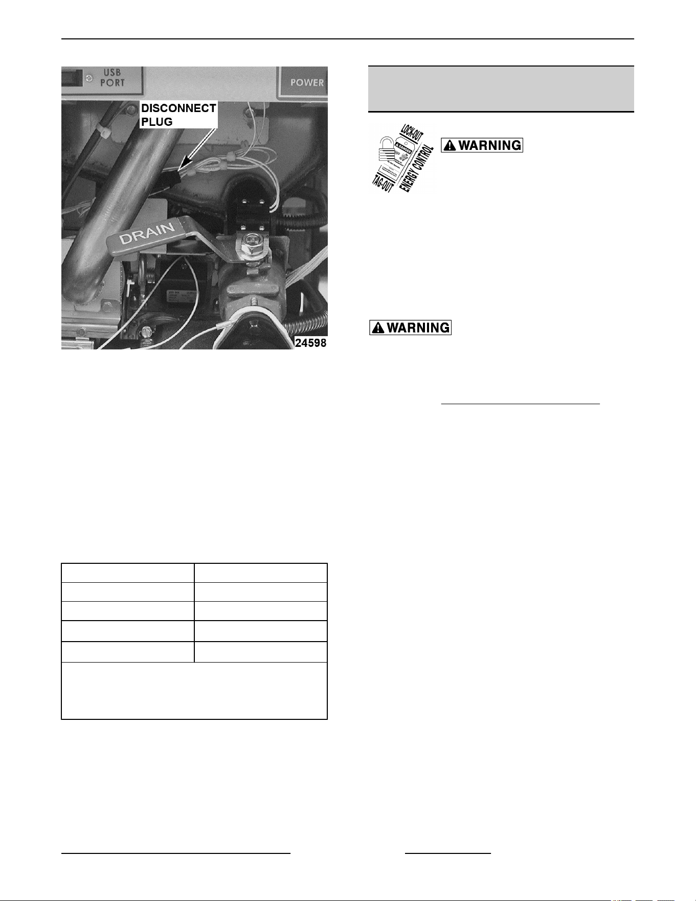
Fig. 48
3. Test the probe using a VOM to measure
resistance. Connect the meter leads to the wires
removed in step 2.
A. If the measured resistance values are within
the allowable range, the probe is functioning
properly. Reverse procedure to install.
B. If the measured resistance values are
outside the allowable range, install a
replacement probe and check for proper
operation.
NOTE: Oil temperatures near or below 40° F will
exhibit OPEN PROBE error message.
TEMPERATURE (°F) RESISTANCE (Ω)
77 90,000 - 110,000
350 604 - 836
415
1
302 - 369
460
2
191 - 233
1
High temperature alarm level for the cooking
controls
2
Shorted probe equivalent temperature
COOKING CONTROL
CALIBRATION
Certain procedures in this section
require electrical test or
measurements while power is
applied to the machine. Exercise
extreme caution at all times and
follow Arc Flash procedures. If test
points are not easily accessible,
disconnect power and follow
Lockout/Tagout procedures, attach
test equipment and reapply power to
test.
Hot oil and parts can cause burns. Use care when
servicing fryer.
NOTE: Verify condition of temperature probe as
outlined under TEMPERATURE PROBE TEST before
proceeding.
1. Check the level of shortening in fry tank. The level
must be between the MIN & MAX fill lines before
proceeding.
2. Allow shortening to cool below 300°F.
3. Place a thermocouple in the geometric center of
the fry tank one inch below the shortening
surface.
4. Set the cooking control to 350°F and turn the fryer
on.
5. Monitor the heat indicator lamp. When cooking
control is calling for heat, lamp will be on. If
cooking control is satisfied, lamp will be off.
Analog Control - Heat light is to right of the ON/
START light.
Solid State Control - Decimal point of first
character indicates heat on when lit.
Computer Control - Two LED lamps on the Oil
Temp key that indicate heat on.
NOTE: Agitate the shortening, to eliminate any cold
zones.
A. Allow cooking control to cycle three times to
stabilize shortening temperature.
B. Record meter reading from thermocouple
when the cooking control cycles off and on
for at least two complete heating cycles.
VK and TR GAS FRYERS W/Wo KleenScreen PLUS - SERVICE PROCEDURES AND ADJUSTMENTS
Page 29 of 64 F45474 Rev. D (0822)
6. Calculate the average temperature by adding the
temperature reading when the heat lamp goes
out to the temperature reading when the heat
lamp comes on & divide this answer by 2.
[ Temp. (Lamp off) + Temp. (lamp on) ] ÷ 2 =
Average Temp. Example: 360° + 340° ÷ 2 =
350°F.
The average temperature should be 350°F (±
5°F).
A. If the average temperature reading is within
tolerance, cooking control is properly
calibrated.
B. If the average temperature reading is out of
tolerance, perform the following:
1) Analog Control - Remove knob and
turn adjustment screw
counterclockwise to increase
temperature and clockwise to
decrease temperature.
2) Solid State Control - Adjust OFFSET
TEMPERATURE.
3) Computer Control - Adjust OFFSET
TEMPERATURE.
7. Repeat the average temperature calculation for
up to three attempts. Allow the cooking control to
cycle at least two times between adjustments
before performing the calculation.
8. If calibration is unsuccessful, the cooking control
may be malfunctioning and cannot be adjusted
properly. Install a replacement cooking control
and check calibration.
FLAME SENSE CURRENT CHECK
PRIOR TO 12/1/12
Certain procedures in this section require
electrical test or measurements while power is
applied to the machine. Exercise extreme caution
at all times. If test points are not easily accessible,
disconnect power and follow lockout / tagout
procedures, attach test equipment and reapply
power to the test.
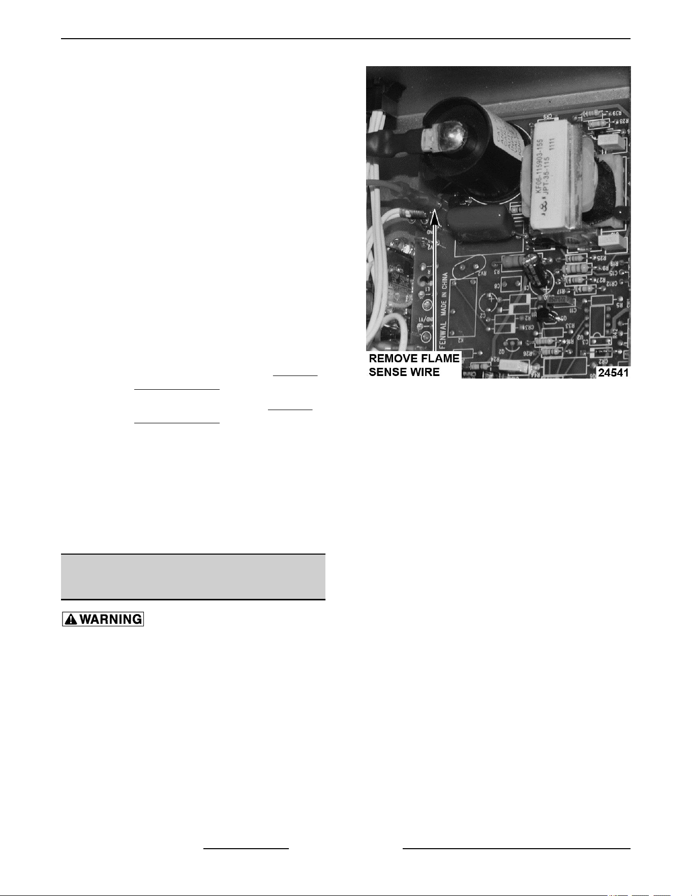
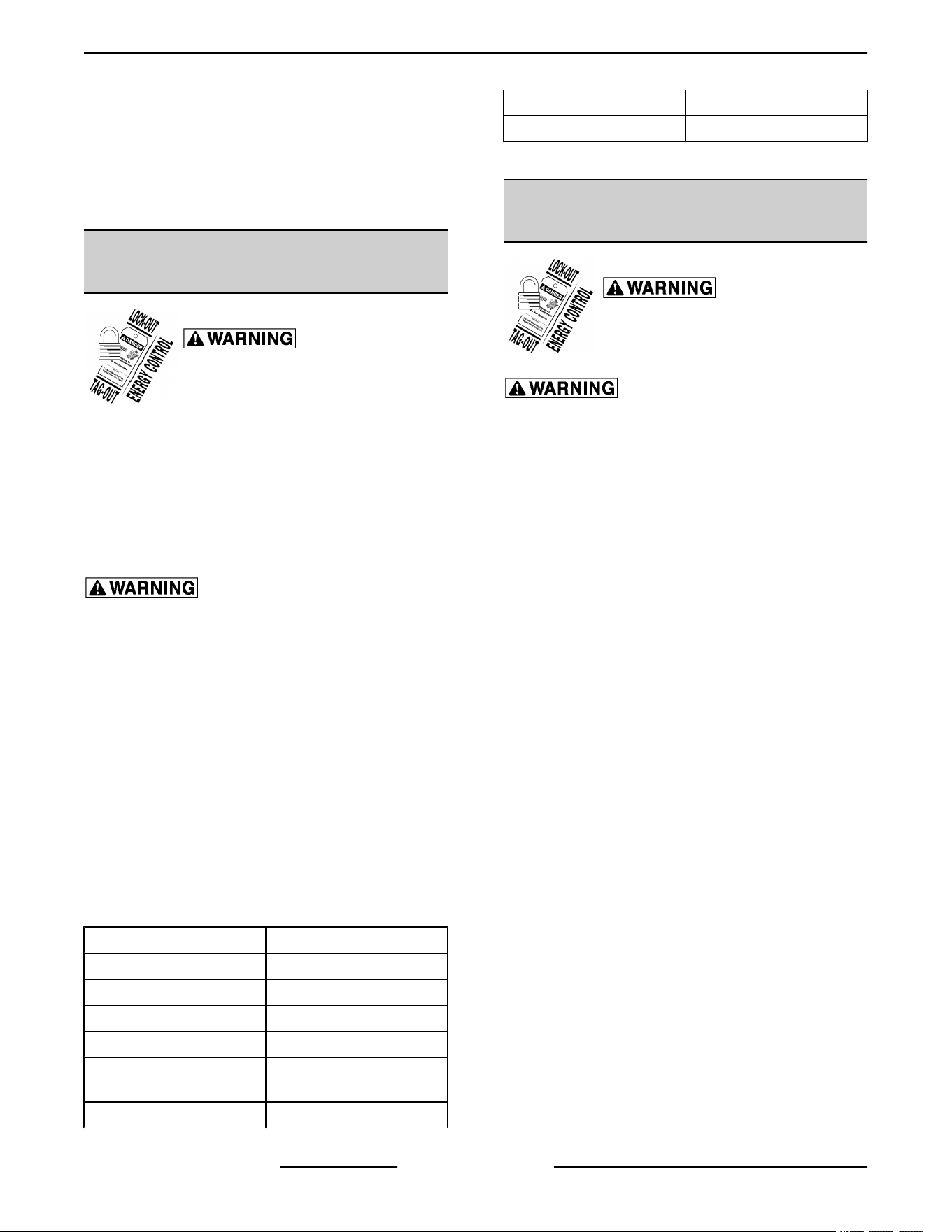
1. Remove cover of power supply box.
2. Locate red flame sense wire.
Fig. 49
3. Remove the red flame sense wire.
4. Place one Microamp meter lead on the red wire.
5. Place the other meter lead on the terminal you
removed the red flame sense wire from.
6. Power up the fryer and have it call for heat.
7. You should receive a minimum Microamp
reading of at least 1.0 microamp.
8. If the reading is greater or equal to the value
given, then the flame sense current is within
tolerance.
9. If the reading is lower than the value given, then
troubleshoot the flame sense circuit.
NOTE: If the reading is below 0.0 microamps, reverse
the meter leads and take another reading.
VK and TR GAS FRYERS W/Wo KleenScreen PLUS - SERVICE PROCEDURES AND ADJUSTMENTS
F45474 Rev. D (0822) Page 30 of 64
FLAME SENSE CURRENT CHECK
AFTER 12/1/12
Certain procedures in this section require
electrical test or measurements while power is
applied to the machine. Exercise extreme caution
at all times. If test points are not easily accessible,
disconnect power and follow lockout / tagout
procedures, attach test equipment and reapply
power to the test.
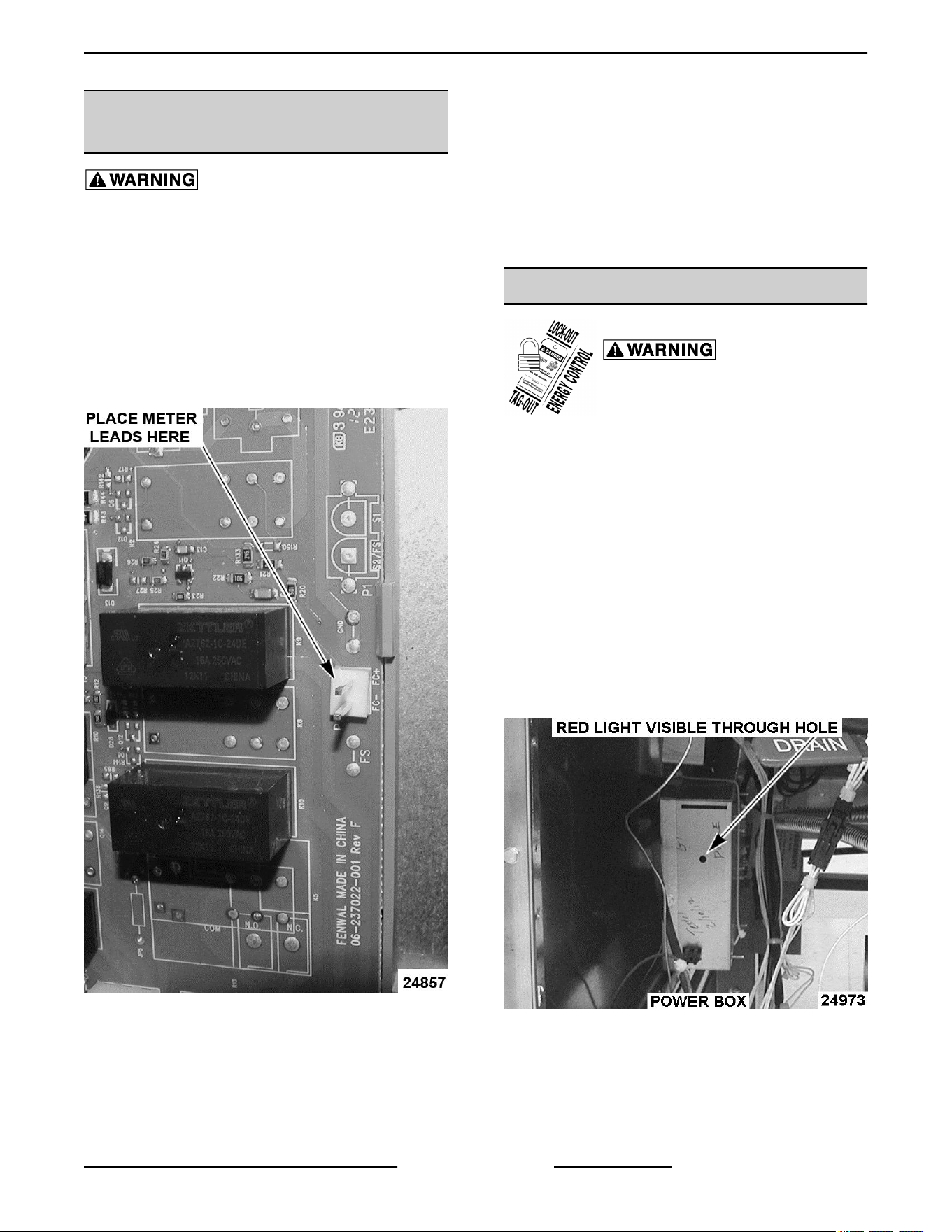
1. Remove cover from power supply box.
2. Locate two pins (FC- and FC+) on side of the
ignition/ blower control board.
Fig. 50
3. Set your multi meter for Microamps and place
meter leads on two pins.
4. Restart the fryer and read the microamps as the
fryer is sparking.
NOTE: Reading the microamps can only be done
when the fryer is sparking. When the spark quits, the
reading will go away. There will be several seconds to
obtain this reading.
5. The flame sense current must be at least 2.0 to
3.0 microamps, and the reading must be steady.
6. If reading is below 1.3 microamp or unsteady,
check pilot flame and electrical connections.
ELECTRONIC IGNITION CONTROL
Certain procedures in this section
require electrical test or
measurements while power is
applied to the machine. Exercise
extreme caution at all times and
follow Arc Flash procedures. If test
points are not easily accessible,
disconnect power and follow
Lockout/Tagout procedures, attach
test equipment and reapply power to
test.
NOTE: This procedure applies to all fryers.
Ignition Module Lockout
This happens when fryer is unable to detect flame
sense. The electrode will try to ignite one time. When
flame has not been detected within 5 seconds red light
on ignition module will blink.
Fig. 51
"A" style controller: Red light will blink and blower will
continue to run until power has been turned off.
"C" and "D" style controllers: Red light will continue to
blink, but blower will shut down after a number of
VK and TR GAS FRYERS W/Wo KleenScreen PLUS - SERVICE PROCEDURES AND ADJUSTMENTS
Page 31 of 64 F45474 Rev. D (0822)
seconds and a loud "beep" will continue to sound until
fryer is powered down.
Electronic Ignition System
Certain procedures in this section
require electrical test or
measurements while power is
applied to the machine. Exercise
extreme caution at all times and
follow Arc Flash procedures. If test
points are not easily accessible,
disconnect power and follow
Lockout/Tagout procedures, attach
test equipment and reapply power to
test.
1. Access burner electrode.
2. Remove ignition wire from burner electrode.
3. Fasten metal end of ignition wire about ¼ away
from a grounded metal surface on fryer.
4. Try to light the burner.
5. Spark should be present. If no spark, check
ignition module in power supply box.
MODULATING GAS VALVE
ADJUSTMENTS
Disconnect the electrical power to
the machine and follow lockout /
tagout procedures.
Shut off the gas before servicing the
unit and follow lockout / tagout
procedures.
All gas joints disturbed during servicing must be
checked for leaks. Check with a soap and water
solution (bubbles). Do not use an open flame.
The modulating gas valve is adjusted at the factory
and requires no adjustments. If the modulating gas
valve needs to be replaced, the new gas valve from
the parts depot will be adjusted property and will only
need to have the gas pressure verified coming into the
gas valve.
BASKET LIFT ARM ADJUSTMENT
Certain procedures in this section
require electrical test or
measurements while power is
applied to the machine. Exercise
extreme caution at all times and
follow Arc Flash procedures. If test
points are not easily accessible,
disconnect power and follow
Lockout/Tagout procedures, attach
test equipment and reapply power to
test.
Hot oil and parts can cause burns. Use care when
servicing the fryer.
1. With shortening at room temperature, verify the
shortening level is between MIN & MAX lines in
fry tank. Add shortening as needed.
NOTE: Shortening will expand when heated. Do not
fill the fry tank past the MAX line.
2. Turn power switch on and set temperature to
350°F. Allow the shortening to reach set
temperature.
3. Check basket lift operation.
A. If necessary, adjust as outlined below.
4. When basket is in the up position, the bottom of
the basket should be out of the shortening. When
basket is in the down position, the bottom of the
basket should clear the crumb screen and the
product should be submerged.
A. To adjust, remove basket arm from lift shaft,
loosen stop nut and turn height adjustment
bolt to raise or lower basket arm as required.
Both baskets should be same height.
B. Tighten stop nut when complete.
NOTE: If adjustment is to low, when the basket is
lowered, it will disengage from basket arm.
VK and TR GAS FRYERS W/Wo KleenScreen PLUS - SERVICE PROCEDURES AND ADJUSTMENTS
F45474 Rev. D (0822) Page 32 of 64
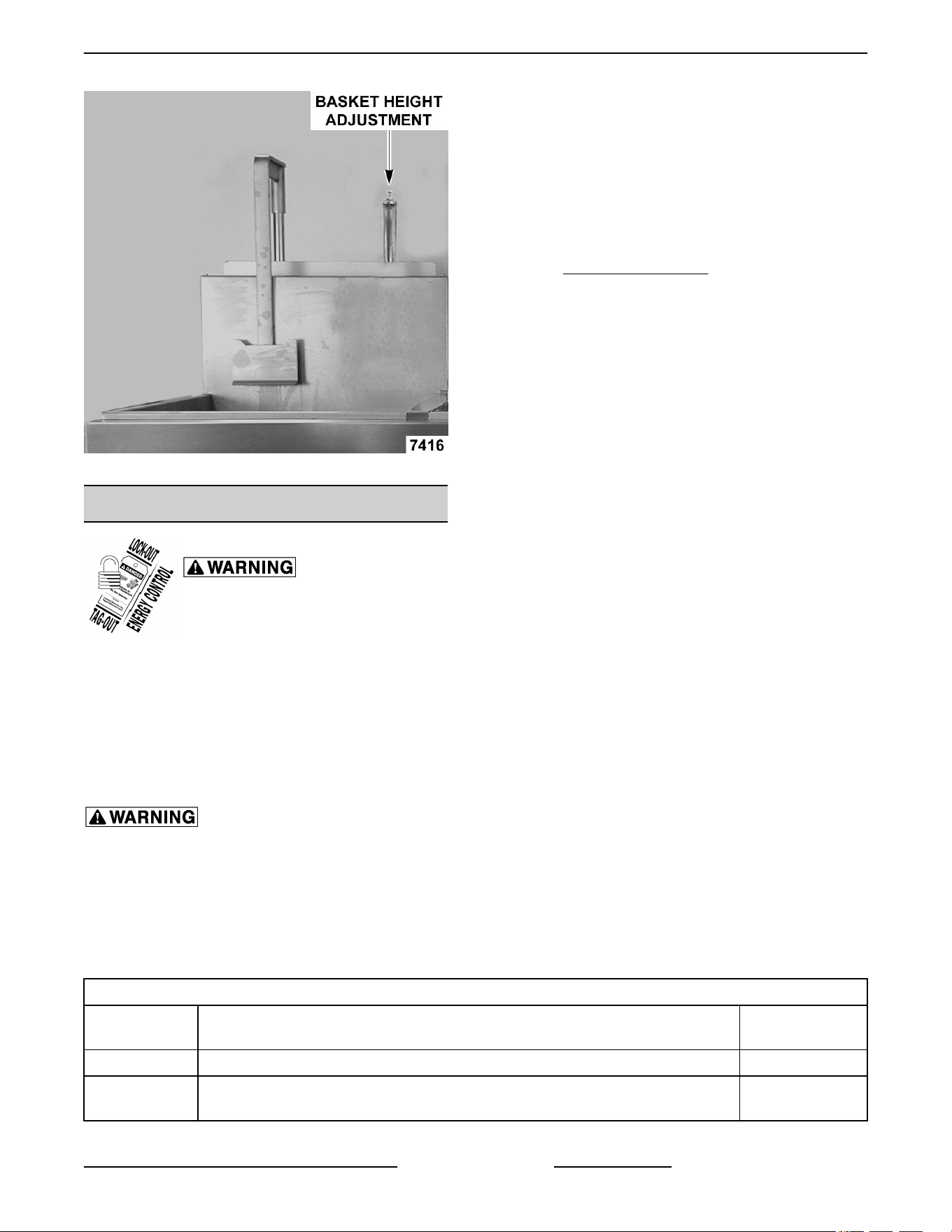
Fig. 52
SOLID STATE CONTROL
Certain procedures in this section
require electrical test or
measurements while power is
applied to the machine. Exercise
extreme caution at all times and
follow Arc Flash procedures. If test
points are not easily accessible,
disconnect power and follow
Lockout/Tagout procedures, attach
test equipment and reapply power to
test.
Hot oil and parts can cause burns. Use care when
servicing the fryer.
Operation
Use service information in this section when servicing
a fryer with a solid state control. Refer to instruction
manual for specific operating instructions.
NOTE: In operator programming mode, control can
be reset to its default values by pressing the TEMP
key for 2 seconds.
Service Programming
Solid state control Service Mode is used to perform
system diagnostic tests or edit programs that affect
the fryers operation.
Error Messages
Refer to ALARM MESSAGES at end of section.
Enter Service Mode
NOTE: Control heat demand output signal is off and
heat/ignition status input signal is ignored.
1. Cycle power switch. When the program version
number is displayed, press PROGRAM key to
enter Service Mode.
A. Beeper chirps on each successful keypress.
2. To scroll through each of the program items,
press PROGRAM key and release.
A. To reset all service mode program items to
factory default, press and hold TEMP key for
2 seconds.
3. To exit Service Mode and save selections, press
PROGRAM key and hold for 1 second. Fryer
returns to normal operation and display shows
the current heating mode based on shortening
temperature:
• MELT L (liquid; default) or Melt S (solid) if
shortening temperature is below 135°F.
• HEATING if no melt is selected and
shortening temperature is below set point.
• Fryer set point temperature if actual
shortening temperature is within set point
range.
Control Programming
PROGRAM
ITEM
KEY SEQUENCE
DISPLAY
1
Brand Name Press left or right basket to select display name. Hobart or Vulcan
Temperature
Display Mode
Press left or right basket to select temperature unit of measure. DEG F OR C
VK and TR GAS FRYERS W/Wo KleenScreen PLUS - SERVICE PROCEDURES AND ADJUSTMENTS
Page 33 of 64 F45474 Rev. D (0822)
Control Programming
PROGRAM
ITEM
KEY SEQUENCE
DISPLAY
1
Boil or Filter
Function
Press left or right basket to select fryer type.
Boil key overlay = stand alone fryer.
Filter key overlay = filtering system fryer batteries.
BOIL OR FILTER
Fryer Type
Press left or right basket to select fryer energy source (electric or gas heat).
Gas Star must be selected for VK and TR Fryers.
4
ELECTRIC or
GAS or GAS
STAR
Calibration
Offset
Press left basket to increase or right basket to decrease offset temperature
(range -20 to 20)
2
OFS 00F (always
in °F)
Low Cook
Temp Lockout
Press left basket to increase or right basket to decrease cooking cycle lockout
temperature. (range 30 to 50F)
2
NOTE: Prevents cook timers from starting if actual shortening temperature is
not within the lockout temperature setting.
LOCKO 40
(always in °F)
NOTE: The program items listed below are for verifying settings only. Do not change the default setting for these
program items.
PROGRAM
ITEM
KEY SEQUENCE
DISPLAY
1
Instant On
Time (heat)
Press left basket to increase or right basket to decrease instant on time.
NOTE: At the start of a cook cycle, the heat output will be activated for this time
(range 0 to 20 seconds).
INSTO 20
Melt Cycle On/
Off Times
Press left basket to increase or right basket to decrease melt cycle time.
3
Gas Fryers
Adjustment Range:
Melt ON - 0 to 20 seconds; Melt OFF - 0 to 30 seconds.
MLTG
1 16
(Liq)
08
(Sol)
(Melt
ON)
MLTG
0 18
(Liq)
26
(Sol)
(Melt
OFF)
Electric Fryers
Adjustment Range:
Melt ON - 0 to 2 seconds; Melt OFF - 10 to 30 seconds.
MLTE1
04
(Liq)
02
(Sol)
(Melt
ON)
MLTE0
11 (liq)
13
(Sol)
(Melt
OFF)
Proportional
Offset
Press left basket to increase or press right basket to decrease proportional
offset (range 0 to 30).
POFST 02
VK and TR GAS FRYERS W/Wo KleenScreen PLUS - SERVICE PROCEDURES AND ADJUSTMENTS
F45474 Rev. D (0822) Page 34 of 64
Control Programming
PROGRAM
ITEM
KEY SEQUENCE
DISPLAY
1
Proportional
Gain
Press left basket to increase or right basket to decrease proportional gain (range
0 to 30).
PGAIN 24
Derivative Gain
Press left basket to increase or right basket to decrease derivative gain (range
0 to 30).
DGAIN 20
Integral Gain
press left basket to increase or right basket to decrease integral gain (range 0
to 30).
IGAIN 08
Integral Limit
Press left basket to increase or right basket to decrease integral limit (range 0
to 255).
ILIM 255
NOTES
1
Default value shown in bold type.
2
Temperature will change in one degree increments, accelerating if the
button is held.
3
Time will change in one second increments, accelerating if the button
is held.
4
Gas* and Gas Star are the same value. The Solid State Display cannot
show an asterick(*).
Display Test
1. Cycle power switch. When FRYERS is
displayed, press PROGRAM key.
A. Display shows DSP TEST.
B. Press PROGRAM key again to light all the
display segments in the first character.
C. Continue pressing PROGRAM key until the
display segments for all eight characters are
tested.
2. To exit test, press and hold the PROGRAM key
for one second.
Alarm Messages
Alarms take precedence over any other controller
mode or function (except drain valve function).
ALARMS DESCRIPTION
OPEN PROBE
If an open probe is detected, the heat demand (heat on) and basket lift outputs are
disabled. Any cooking in progress is cancelled and all operator buttons are disabled.
the display alternates OPEN PROBE and the electronic alarm will sound
continuously.
NOTE: A temperature of 40°F or lower is an open probe equivalent.
SHORTED PROBE
If a shorted probe is detected, the heat demand (heat on) and basket lift outputs are
disabled. Any cooking in progress is cancelled and all operator buttons are disabled.
The display alternates SHORTED PROBE and the electronic alarm will sound
continuously.
NOTE: A temperature of 460°F or greater is a shorted probe equivalent.
HI TEMP
If the temperature is greater than or equal to 415°F, the heat demand (heat on) and
basket lift outputs are disabled. Any cooking in progress is cancelled and all operator
buttons are disabled. The display alternates HIGH TEMP and the electronic alarm
will sound continuously. Normal fryer operation resumes when the temperature
drops below the high temperature alarm level.
VK and TR GAS FRYERS W/Wo KleenScreen PLUS - SERVICE PROCEDURES AND ADJUSTMENTS
Page 35 of 64 F45474 Rev. D (0822)

ALARMS DESCRIPTION
IGNITION STATUS (gas
models only)
If the ignition status input to the control is active (24VAC = active), the display shows
IGNITION LOCKOUT, the electronic alarm will sound continuously, and the
controller will be disabled (all outputs including heat demand off) until power is
cycled.
DRAIN VALVE INTERLOCK
(DVI) Filtering System Fryer
Batteries (Filter Key)
When drain valve is opened, the DVI switch contacts open, and the 24VAC input to
the control is removed. The heat demand (heat on) and basket lift outputs are
disabled. Any cooking in progress is cancelled and all operator buttons are disabled.
The display will show DRAINING.
Press FILTER key and hold for 3 seconds to begin filtering (pump on). Control is
signaled that filtering has started.
When the drain valve is closed, the DVI switch contacts close, and the 24VAC input
to the controller is restored. The heat demand (heat on) and all operator buttons will
remain disabled and the display will show FILL VAT.
To resume operation, allow the tank to fill with shortening between the MIN and MAX
lines. Press FILTER key to turn the pump motor off. Control is signaled that filtering
has stopped and the tank is full, Display will ask VAT FULL HIT TEMP. Press TEMP
key after confirming the shortening is at the proper level and to resume heating.
DRAIN VALVE INTERLOCK
(DVI) Stand Alone Fryers (Boil
Key)
When drain valve is opened, the DVI switch contacts open, and the 24VAC input to
the control is removed. The heat demand (heat on) and basket lift outputs are
disabled. Any cooking in progress is cancelled and all operator buttons are disabled.
The display will show DRAINING.
When the drain valve is closed, the DVI switch contacts close, and the 24VAC input
to the controller is restored. The heat demand (heat on) and all operator buttons will
remain disabled and the display will show FILL VAT HIT TEMP.
To resume operation, allow the tank to fill with shortening between the MIN and MAX
lines. Press TEMP key. Display will ask VAT FULL HIT TEMP. Press TEMP key a
second time after confirming the shortening is at the proper level and to resume
heating.
PROGRAM LOST RECHECK
When the program has detected errors in the data that is stored in the controls non
volatile memory (EEPROM), the control will automatically reload the factory default
settings. Display will alternate the alarm message until program mode is entered
then exited or power is cycled to control.
IGNITION STATUS
GAS Selected incorrectly
under service settings - type
If the display shows NO PILOT, there is an incorrect service setting.
Enter SERVICE SETTINGS and select GAS STAR as the type.
VK and TR GAS FRYERS W/Wo KleenScreen PLUS - SERVICE PROCEDURES AND ADJUSTMENTS
F45474 Rev. D (0822) Page 36 of 64
COMPUTER CONTROL
Certain procedures in this section
require electrical test or
measurements while power is
applied to the machine. Exercise
extreme caution at all times and
follow Arc Flash procedures. If test
points are not easily accessible,
disconnect power and follow
Lockout/Tagout procedures, attach
test equipment and reapply power to
test.
Hot oil and parts can cause burns. Use care when
servicing the fryer.
Operation
For operating instructions and programming, refer to
OPERATOR MANUAL and computer controls
programing start guide.
Fig. 53
Service Programming
The computer controls service settings mode is used
to select the settings that affect fryer operation and to
perform fryer diagnostic tests.
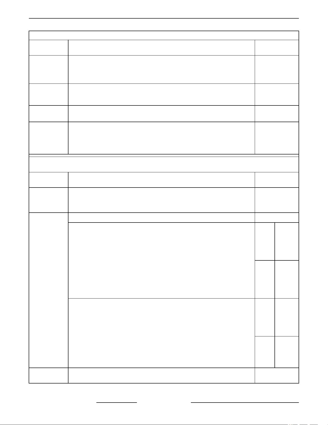
Enter Service Setting Mode
Fig. 55
NOTE: The controls heat demand output signal is off
and the heat/ignition status input signal is ignored if
the fryer is in cook mode or idling.
1. Turn power switch on and when the program
revision is displayed, press PROGRAM to enter
Service Setting Mode.
A. The SERVICE SETTINGS are shown on the
left and right display screens.
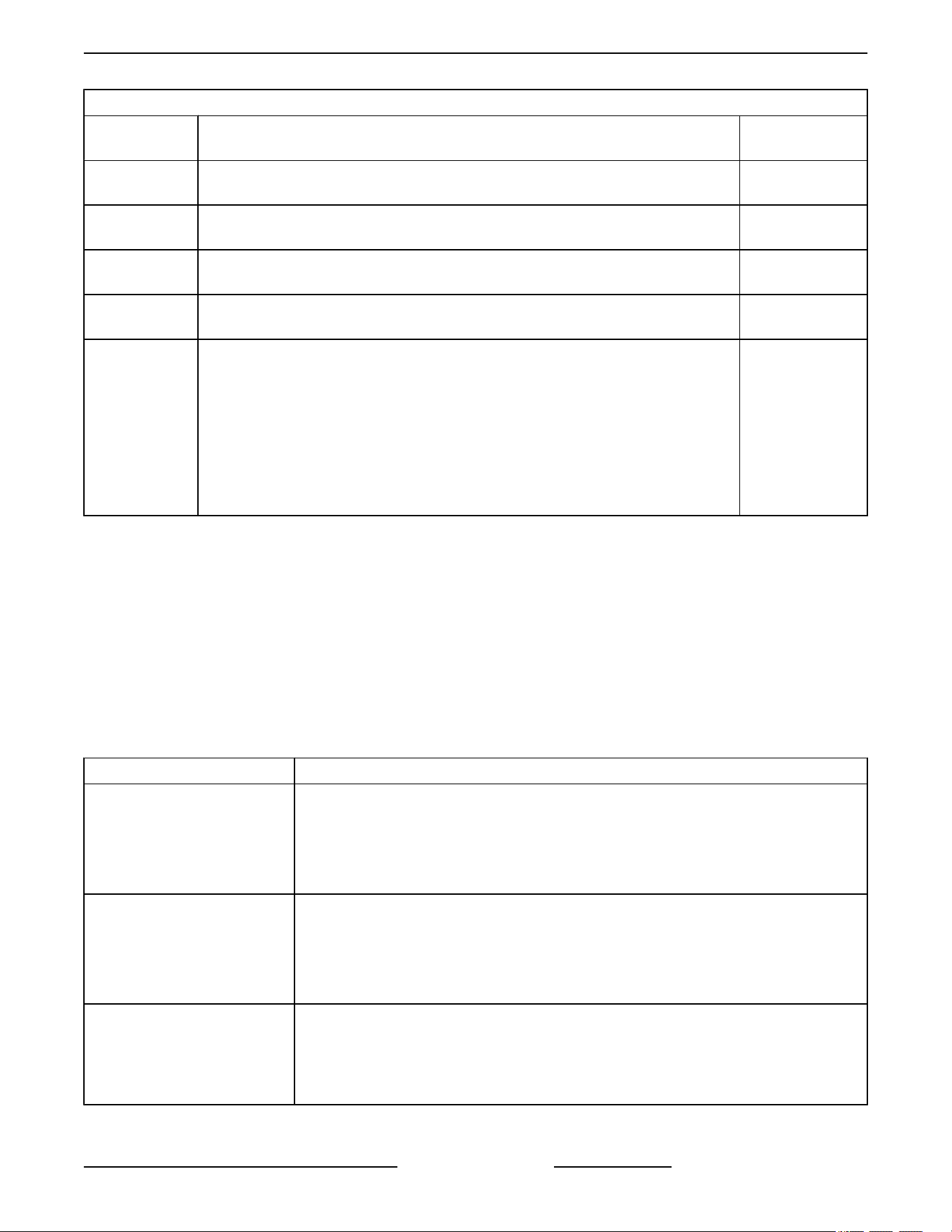
2. Verify the settings shown on the display screen
are correct for the fryer being serviced.
3. To change a service setting.
A. Press the desired product number key (1
thru 6) on the control panel that corresponds
to the service setting number on the display
screen.
1) Beeper chirps on each successful key
press and all LED's are off. When a
service item is selected, only the keys
required to change the setting are
active.
B. Press toggle key to alternate between
available selections, or use product number
keys where indicated to enter a value. The
current selection will be "blinking".
C. Press PROGRAM key to save the selection
- "Blinking" stops.
D. Access the other service settings as
necessary.
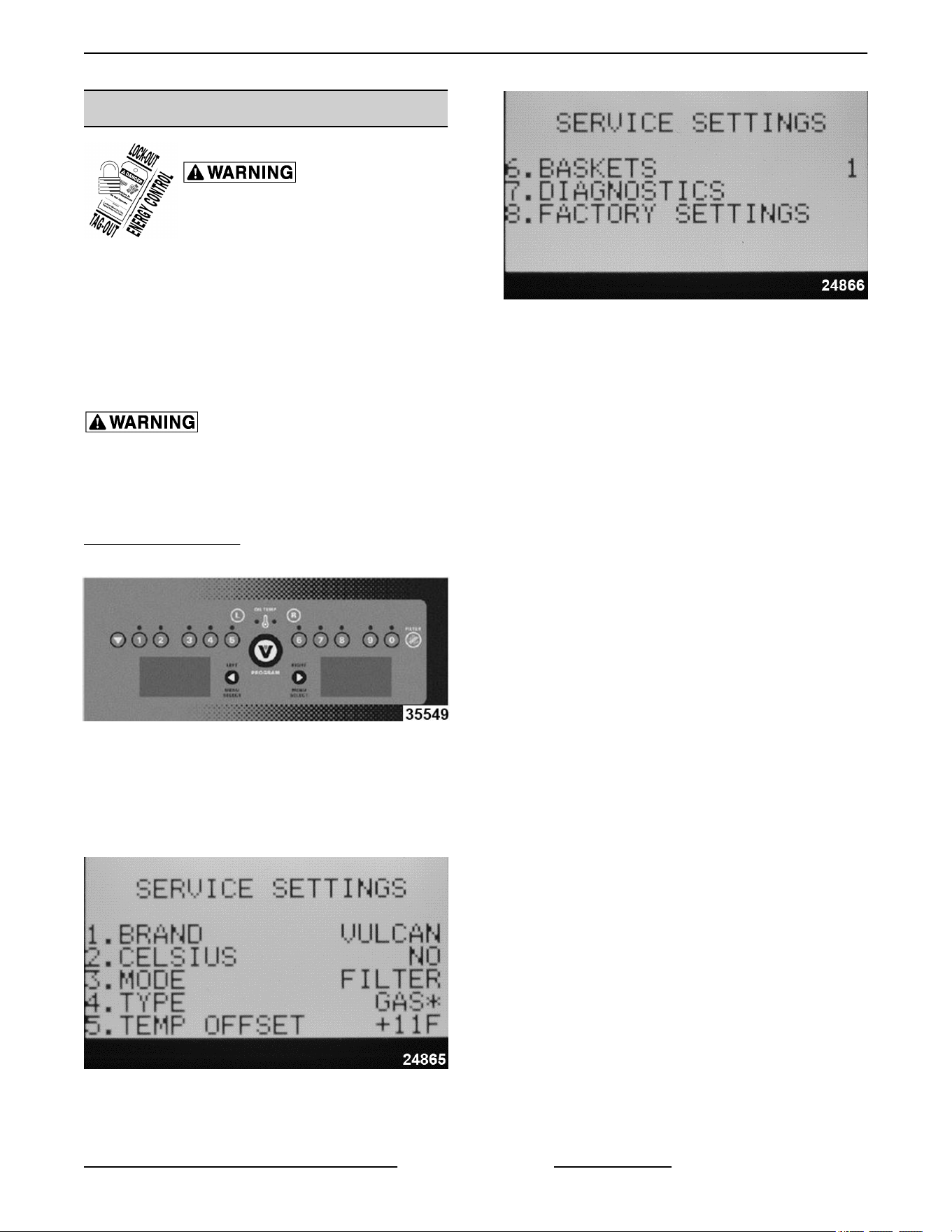
4. To enter DIAGNOSTICS mode, press product
number key 7 on the control panel.
VK and TR GAS FRYERS W/Wo KleenScreen PLUS - SERVICE PROCEDURES AND ADJUSTMENTS
Page 37 of 64 F45474 Rev. D (0822)
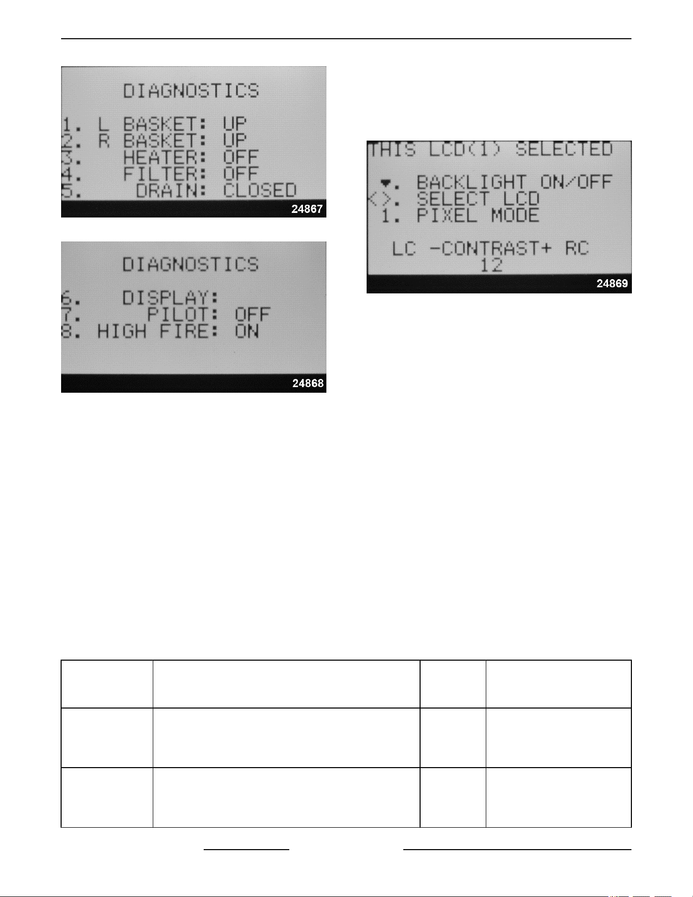
Fig. 56
Fig. 57
A. Press the desired product number key (1, 2,
3, 4, & 6) on the control panel that
corresponds to the diagnostic test number
on the display screen to check the output
signal to the component.
1) Press the same product number key
again to turn the output off.
NOTE: Item 5 (drain) displays the real time status and
does not require pressing the corresponding product
number key. Item 3 (heater) - The output signal will be
active for 3 seconds (heat on) then turn off.
B. For item 6 DISPLAY: - change the setting as
desired.
1) Press product number key 6 to access
the display screen adjustment settings.
2) Press the left or right arrow key on the
PROGRAMMING MENU SELECTION
screen to select the screen to adjust.
Display shows "THIS LCD
SELECTED".
Fig. 58
3) To adjust the selected screen:
a. BACKLIGHT - Press toggle key to
turn display backlight ON or OFF.
b. PIXEL MODE - Press product key
number 1 two times to change
display from white background
with black letters to black
background with white letters.
Press the key again to change it
back to original setting.
c. CONTRAST - Press the L key on
the keypad to lower the contrast or
press the R key on the keypad to
raise the contrast.
4) Press PROGRAM key to return to
DIAGNOSTICS MODE.
5. To exit SERVICE SETTINGS MODE and return
to normal operation, keypress PROGRAM key.
A. Display reverts to product menu items.
SERVICE
SETTINGS
KEY SEQUENCE
DISPLAY
ITEM
FLASHES
1
DESCRIPTION
1. Brand
Press 1 to change brand name.
Press toggle key to select HOBART or VULCAN.
Press PROGRAM Key to save the selection.
VULCAN Brand name at power on
2. Celsius
Press 2 to change temperature scale.
Press toggle key to select NO or YES.
Press PROGRAM Key to save the selection.
NO
Temperature °F/°C
No = Fahrenheit
Yes = Celsius
VK and TR GAS FRYERS W/Wo KleenScreen PLUS - SERVICE PROCEDURES AND ADJUSTMENTS
F45474 Rev. D (0822) Page 38 of 64
SERVICE
SETTINGS
KEY SEQUENCE
DISPLAY
ITEM
FLASHES
1
DESCRIPTION
3. Mode
Press 3 to change fryer mode.
Press toggle key to select BOIL or FILTER.
Press PROGRAM Key to save the selection.
Boil
Boil or Filter
Boil key = Stand alone fryer
Filter key = Filter system
battery
4. Type
Press 4 to change energy source.
Press toggle key to select ELECTRIC, GAS or GAS*.
NOTE: VK and TR Gas Fryers MUST be set to
GAS*.
Press PROGRAM Key to save the selection.
ELECTRIC Electric, Gas or Gas*
5
Temp Offset
Press 5 to change offset temperature.
Press toggle key to change offset value to (+) or (-)
(positive or negative).
Enter the offset value using the number keys on the
keypad.
NOTE: Offsets the actual oil temp sensed by the
temperature probe during calibration. Enter a positive
number to decrease the actual oil temperature; or a
negative number to increase the oil temperature.
Press PROGRAM Key to save the selection.
OFF 00 F
(always in
°F)
Degrees Fahrenheit and
positive zero are the
defaults.
6. Baskets
Press 6 to change the number of basket lifts.
Press toggle key to select 0, 1, or 2.
Press PROGRAM Key to save the selection.
2 Display shows 0, 1 or 2
7. Diagnostics
Press 7 to enter diagnostic mode (outputs for heat,
basket lifts and cooking timers remain off).
___
DIAGNOSTICS
(shown on display screen)
1.) L Basket
Press 1 to toggle left basket lift output to lower the lift. DOWN Lowers basket
Press 1 again to raise the lift. UP Raises basket
2.) R Basket
Press 2 to toggle right basket lift output to lower the
lift.
DOWN Lowers basket
Press 2 again to raise the lift. UP Raises basket
3.) Heater
Press 3 to turn heat output ON for 3 seconds only.
OIL TEMPERATURE LED's light with heat demand.
On then
OFF
Gas burner or heating
elements turn on then off.
4.) Filter
Press 4 to turn filter output ON. ON Pump motor on
NOTE: Filtering system fryer batteries only.
Press 4 again to turn output OFF. OFF Pump motor off
5.) Drain
Display indicates the position of the drain valve. (DVI
switch input to control) (keypress not required).
Manually change valve position to test, and display
will update.
CLOSED
Drain valve open. OPEN
Drain valve closed. CLOSED
VK and TR GAS FRYERS W/Wo KleenScreen PLUS - SERVICE PROCEDURES AND ADJUSTMENTS
Page 39 of 64 F45474 Rev. D (0822)

SERVICE
SETTINGS
KEY SEQUENCE
DISPLAY
ITEM
FLASHES
1
DESCRIPTION
6.) Display
Press 6 to adjust the left and right display screen
settings. Refer to LCD display screen picture under
ENTER SERVICE SETTINGS MODE.
Press the left or right arrow key on control panel to
select the screen to adjust.
To adjust the selected screen:
• BACKLIGHT - Press toggle key to turn display
backlight ON or OFF.
• PIXEL MODE - Press product key number 1 two
times to change display from white background
with black letters to black background with white
letters. Press the key again to change it back to
original setting.
• CONTRAST - Press the L key on the keypad to
lower the contrast or press the R key on the
keypad to raise the contrast.
N/A THIS LCD SELECTED
Exit Diagnostic
and Service
Mode
Press PROGRAM Key to exit the selected
DIAGNOSTICS test and return to Service Settings
Mode.
N/A
SERVICE SETTINGS
(shown on display screen)
NOTES:
1
Default values shown in bold.
Alarm Messages
The alarms take precedence over any other controller
mode or function (outputs off, active timers canceled).
ALARMS DESCRIPTION
PROBE FAULT
If a temperature probe fault occurs, the alarm sounds continuously and the
display shows PROBE on the left display and either OPEN or SHORT on the
right display. This alarm state will remain until the fault clears or power switch
is cycled.
• OPEN - Probe detects temperature less than 40°F.
• SHORTED - Probe detects temperature greater than 460°F.
IGNITION STATUS
GAS -Selected under service
settings - Type.
If the ignition status input is not present, both displays show IGNITION
LOCKOUT. If the input comes back in less than 8 seconds, the displays will
revert to normal operation.
If the input remains inactive for more than 90 seconds, IGNITION LOCKOUT
will be shown on the left display and CHECK GAS SUPPLY will be shown right
display, and the alarm will sound continuously. This alarm state will remain until
power switch is cycled.
IGNITION STATUS
GAS Selected incorrectly under
service settings - Type.
If the display shows NO PILOT, there is an incorrect service setting.
Enter SERVICE SETTINGS and select GAS* as the type.
VK and TR GAS FRYERS W/Wo KleenScreen PLUS - SERVICE PROCEDURES AND ADJUSTMENTS
F45474 Rev. D (0822) Page 40 of 64
GAS INLET PRESSURE CHECK
Hot oil and parts can cause burns. Use care when
servicing the fryer.
1. Turn gas supply off.
2. Access blower in fryer.
3. Loosen screw inside brass port several rotations.
NOTE: Screw will not fall out of port.
Fig. 59
4. Install manometer tube over brass port.
5. Turn gas supply on.
6. Check gas inlet pressure.
BUILDING SUPPLY PRESSURE
NOTE: Recommended W.C.
• Natural Gas 7 - 9" W.C.
• Propane Gas 11 - 12" W.C.
Building supply pressure max ½ psi. (14"
W.C.)
If incoming pressure exceeds 14" W.C. (1⁄2 psig -3.45
kPa), a step-down pressure regulator must be
installed.
If building supply pressure is too high or low, contact
facility manager to have corrected.
Never attempt to field adjust the gas valve settings.
Doing so will ruin the gas valve calibration, lead to
component failures and cause incorrect combustion
gases output.
7. Turn gas supply off.
8. Remove manometer.
9. Tighten brass port screw.
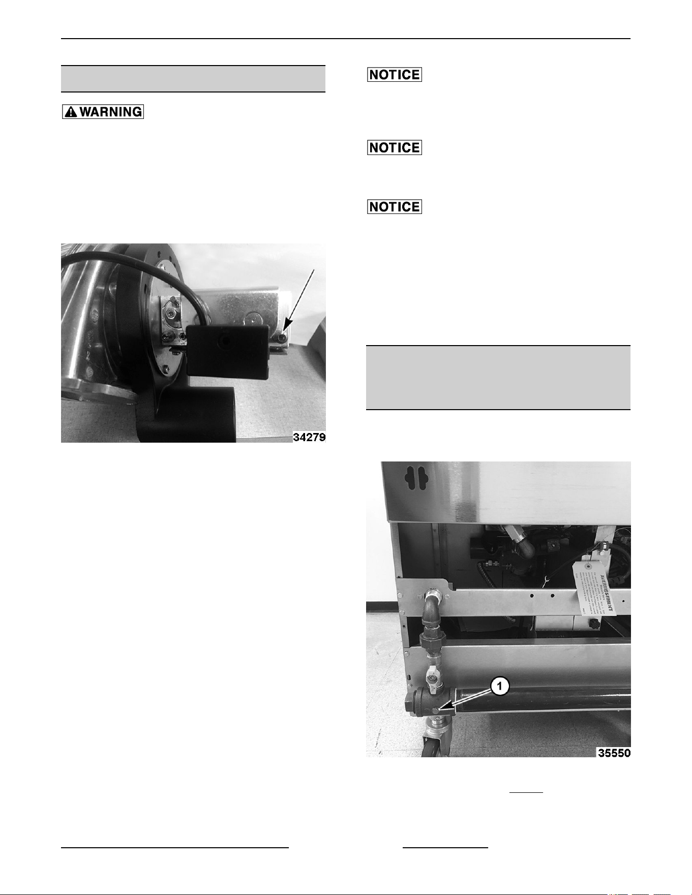
ALTERNATE GAS INLET
PRESSURE CHECK (BATTERY
UNITS)
1. Turn gas supply off.
2. Access rear gas manifold.
Fig. 60
3. Remove 1/8" NPT plug (Fig. 60,1) in manifold tee
on the far right.
4. Install manometer.
VK and TR GAS FRYERS W/Wo KleenScreen PLUS - SERVICE PROCEDURES AND ADJUSTMENTS
Page 41 of 64 F45474 Rev. D (0822)
5. Turn gas supply on.
6. Check gas inlet pressure.
7. Turn gas supply off.
8. Remove manometer.
9. Replace 1/8" NPT plug.
DISPLAY, LED AND KEYPAD TEST
- COMPUTER CONTROL
Certain procedures in this section
require electrical test or
measurements while power is
applied to the machine. Exercise
extreme caution at all times and
follow Arc Flash procedures. If test
points are not easily accessible,
disconnect power and follow
Lockout/Tagout procedures, attach
test equipment and reapply power to
test.
Hot oil and parts can cause burns. Use care when
servicing the fryer.
1. Press and hold the 5 key while turning power on
to Initiate test. Release the 5 key during display
of software revision level and all LED<s and
display segments should light.
2. For each number key (1-9, & 0) pressed, the
corresponding value is displayed in each
character position on the left and right display.
(i.e.5 key shows 55555555 55555555).
NOTE: Beeper chirp’s for as long as key is held.
3. For each function key pressed, the following
values are displayed in each character position
on the left and right display:
L (left) L Cook
R (right) R Cook
TEMPERATURE Temp
PROGRAM (V) Program
TOGGLE Toggle
BOIL
B (single floor model
fryers)
FILTER D (Kleenscreen fryers)
LEFT TIME < (Left Arrow)
RIGHT TIME > (R Arrow)
4. Turn power off to exit test.
BLOWER CONTROL BOARD
SETTINGS (BEFORE 12/1/12)
Disconnect the electrical power to
the machine and follow lockout /
tagout procedures.
Hot oil and parts can cause burns. Use care when
servicing the fryer.
NOTE: This procedure for fryers built before
12/1/2012.
Whenever you have problems with the blower motor
make sure the following adjustments are correct.
1. SW2: Set the SW2 potentiometer to the number
2 setting.
2. SW4: Set the SW4 potentiometer to the number
4 setting.
3. Dip switches: Set the fourth switch (the one
closest to the potentiometers) to the up position.
VK and TR GAS FRYERS W/Wo KleenScreen PLUS - SERVICE PROCEDURES AND ADJUSTMENTS
F45474 Rev. D (0822) Page 42 of 64
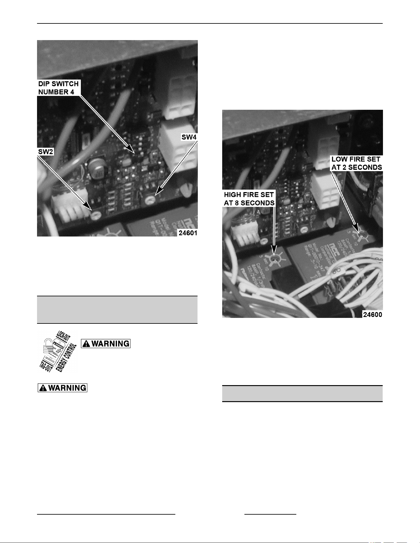
Fig. 61
NOTE: For fryers built after 12/1/2012, there are no
adjustments for blower settings, The Ignition/Blower
control board is preprogrammed. If a fryer built before
12/1/12 has been converted to the new Ignition/
Blower control board, there will be no adjustments.
HIGH/LOW FIRE TIMER (SETTING
BEFORE 2/1/12)
Disconnect the electrical power to
the machine and follow lockout /
tagout procedures.
Hot oil and parts can cause burns. Use care when
servicing the fryer.
NOTE: This procedure is for fryers built before
12/1/2012.
Whenever you have problems with high or low firing
of the burner make sure the following adjustments are
correct.
NOTE: To set the fire timers use a jeweler's flathead
screwdriver.
NOTE: The timer closest to the ignition module is the
low fire timer, and the one closest to the bottom is the
high fire timer.
1. Low fire timer: Set the low fire timer for 2
seconds.
2. High fire timer: Set the high fire timer for 8
seconds.
Fig. 62
NOTE: For fryers built after 12/1/12, the fire timers
are replaced by a Ignition/Blower control board. The
high and low fire time settings are programmed into
the control board. If a fryer built before 12/1/12 has
been converted to the new Ignition/Blower control
board, there will be no adjustments.
AIR FILTER
A dirty air filter will prevent the correct amount of air
intake for the blower. The results are poor combustion
resulting in the fryer "puffing" severely.
To clean the air filter, remove the filter by pulling it off.
The clamp is only hand tightened. Clean air filter in
dishwasher or in sink with hot soapy water. Make sure
air filter is completely dry prior to reinstalling, making
sure that the filter is snug onto the blower intake. Make
sure NOT to tighten the clamp more than hand tight.
The air filter should be removed and cleaned every
VK and TR GAS FRYERS W/Wo KleenScreen PLUS - SERVICE PROCEDURES AND ADJUSTMENTS
Page 43 of 64 F45474 Rev. D (0822)
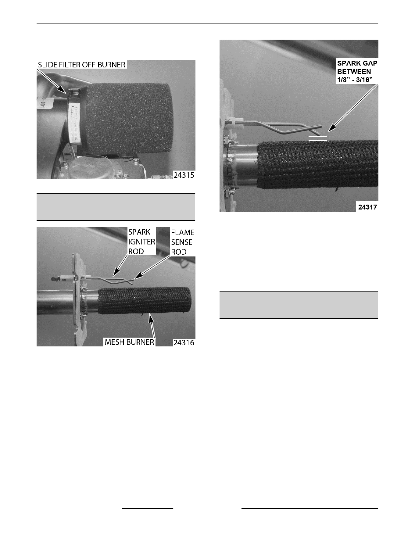
three months. Air filters are only installed on the VK
series fryers.
Fig. 63
SPARK GAP SETTING BEFORE
12/1/12
Fig. 64
The spark igniter rod should be set between 1/8" and
3/16" away from the mesh burner. This gap will allow
the igniter to produce the optimal spark required to
ignite the burner.
Fig. 65
If the spark igniter rod is not adjusted correctly the gas
could build up in the burner assembly and cause a
delayed ignition of the burner. The resulting "puffing"
could result in damage to the fryer.
NOTE: If the power supply box has been converted
to the new controls, the spark igniter rod should be
replaced with the new style spark rod.
SPARK GAP SETTING AFTER
12/1/12
1. Insure the spark igniter is installed properly on
the burner.
2. The ground rod should be set touching mesh or
with a maximum gap between rod and burner
mesh of 1/16 of an inch.
VK and TR GAS FRYERS W/Wo KleenScreen PLUS - SERVICE PROCEDURES AND ADJUSTMENTS
F45474 Rev. D (0822) Page 44 of 64
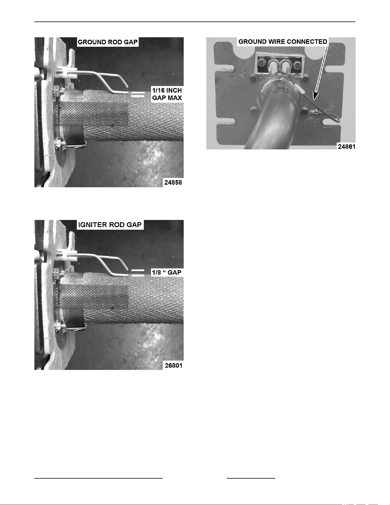
Fig. 66
3. There should be a gap of 1/8 inch between igniter
rod and ground rod.
Fig. 67
4. This igniter sparks to the ground rod. To insure
we have a proper ground, we put a wire on the
ground rod terminal and secure it to burner.
Fig. 68
VK and TR GAS FRYERS W/Wo KleenScreen PLUS - SERVICE PROCEDURES AND ADJUSTMENTS
Page 45 of 64 F45474 Rev. D (0822)

ELECTRICAL OPERATION
COMPONENT FUNCTION - FRYER CONTROLS
Ignitor/ Ground (After
12/1/12) ...............
Ignites the gas burner and senses the presence of a flame. The flame presence generates
a micro-amp flame sense current that is rectified to the ignition control module.
Ignition/Blower control
board (After
12/1/12) ...............
Provides the output signal interface from the cooking control to operate the burner blower
motor in low or high speeds, controls and monitors gas burner ignition. Monitors the
presence of a flame and supplies an ignition status input signal to the cooking control,
Analog (A), Solid State
(D) or Computer
Cooking Control
(C) ....................
Monitors and evaluates input signals to the control: Activates heat output signal to
maintain shortening temperature; counts product cook time(s) and signals the electronic
alarm at the end of a cooking cycle; activates the left and right lift output signal to operate
the basket lifts(s); and activates filter output signal to power the fill solenoid valve.
NOTE: By utilizing the same wiring harness connections D and C controls are
interchangeable between fryers.
Control Interface
Board (D and C fryers
only) ..................
Provides the output signal interface from the cooking control to regulate gas heating,
basket lift operation and fill solenoid valve operation. The board components consist of
a heat control Triac and K1, K2 & K3 N.O. relays.
Transformer .......... Supplies 24VAC to the cooking control, also supplies power to ignition control module.
Transformer is energized when power switch is turned on.
Power Switch ......... Supplies power to control circuit for fryer operation and filtering.
Modulating Gas
Valve .................
Allows the gas flow to modulate between low and high flame when gas valve coil is
energized.
High Limit
Thermostat ...........
Prevents the shortening from reaching temperatures over 450°F (auto reset @ 415°F).
Serves as a backup to the cooking control’s high temperature alarm setting of 415°F
(normal operation resumes when temperature falls below this point).
Temperature Probe ... Senses temperature of shortening. Converts the temperature into a resistance valve
which is monitored by the cooking control. The probe is an RTD (resistance temperature
detector) of the Thermistor type. As temperature increases the resistance value
decreases.
Drain Valve Interlock
Switch (DVI) ..........
A magnetic reed switch mounted on the manual drain valve that supplies a drain valve
position signal (open/closed) to the cooking control. When drain valve is open, the drain
interlock input to the control is removed (magnetic reed switch contacts open). This
prevents gas burners from coming on with the fry tank empty.
Ignition Control
Module (Before
12/1/12) ...............
Controls and monitors gas burner ignition. Monitors the presence of a flame and supplies
an ignition status input signal to the cooking control.
Ignitor/Flame Sense
(Before 12/1/12) .......
Ignites the gas burner and senses the presence of a flame. The flame presence generates
a micro-amp flame sense current that is rectified to the ignition control module.
Burner Time Delay
Relays (Before
12/1/12) ...............
These relays are used in conjunction with the burner either in high or low fire settings.
Blower Relay (Before
12/1/12) ...............
When the relay coil is energized, it supplies voltage to operate the burner blower motor.
Blower Control Board
(Before 12/1/12) .......
Provides the output signal interface from the cooking control to operate the burner blower
motor in low or high speeds. The board components consist of 4 dip switches, SW2 and
SW4.
VK and TR GAS FRYERS W/Wo KleenScreen PLUS - ELECTRICAL OPERATION
F45474 Rev. D (0822) Page 46 of 64
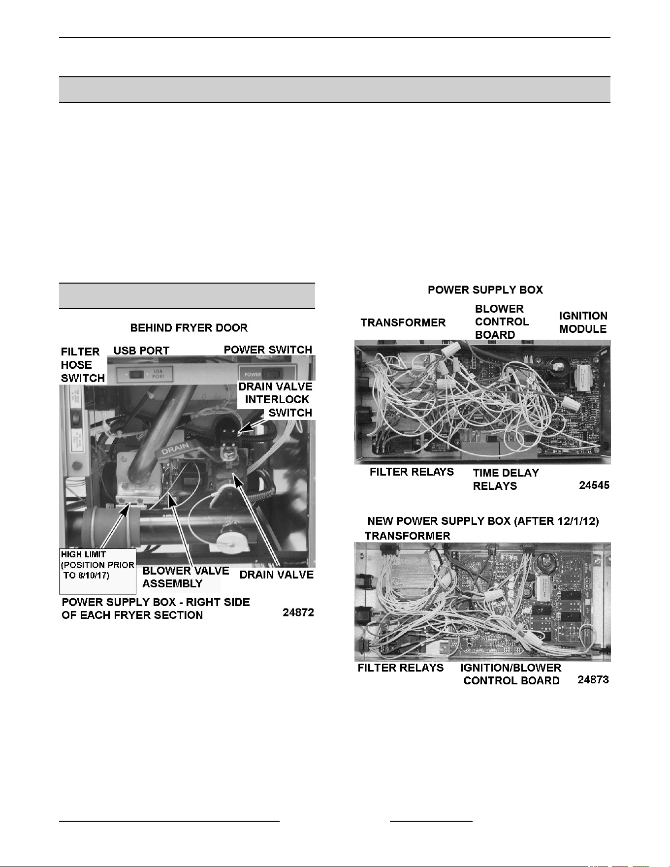
COMPONENT FUNCTION - KLEENSCREEN FILTER CONTROLS
Fill Solenoid Valve .... When energized by filter key, the solenoid valve opens to allow the flow of shortening
thru filtering system.
Pump Motor .......... Operates pump to circulate shortening through filtering system.
Drain Valve Interlock
Switch (DVI) ..........
A magnetic reed switch mounted on the mechanical discard valve that closes when
discard valve handle is extended to discard the shortening. Prevents R2 filter relay N.C.
contacts from suppling power to the fill solenoid valve when filter key is pressed.
R1 Pump Motor
Relay .................
When 24VAC relay coil is energized by filter key, supplies 120VAC to pump motor; and
fill solenoid valve (thru R2 fill relay N.C. contacts.
R2 Fill Relay .......... When 24VAC relay coil is energized by filter key, supplies 24VAC to the fill solenoid valve
to open the valve and allow shortening to flow thru filter system.
COMPONENT LOCATION
Fig. 69
Fig. 70
Fig. 71
VK and TR GAS FRYERS W/Wo KleenScreen PLUS - ELECTRICAL OPERATION
Page 47 of 64 F45474 Rev. D (0822)
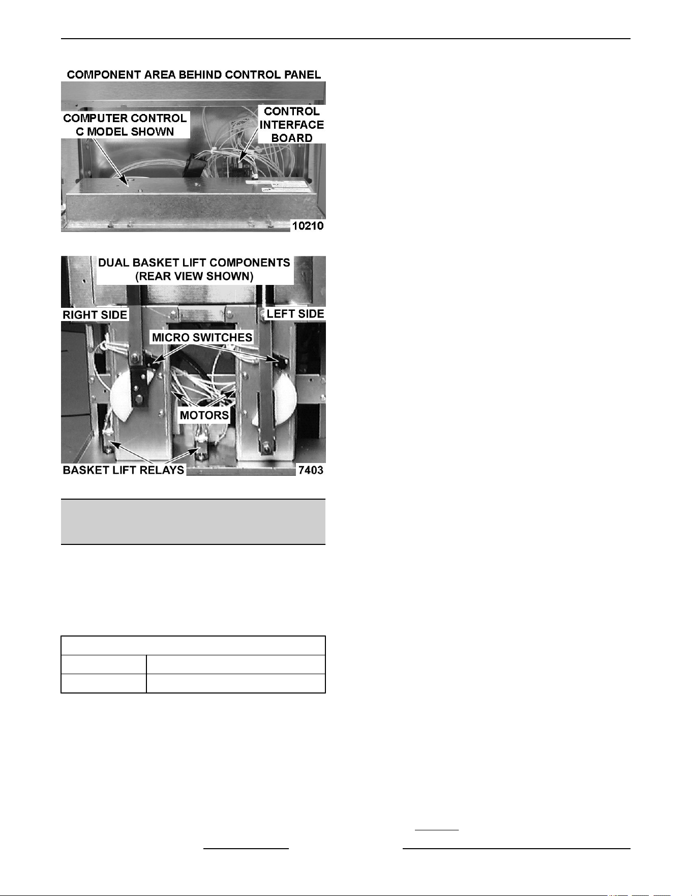
Fig. 72
Fig. 73
SEQUENCE OF OPERATION - A
SERIES - AFTER 12/1/12
Refer to the schematic diagrams for Analog Control
operation.
NOTE: If the Solid/ Liquid switch is set to Solid, the
control will cycle the heat on and off in short intervals
until the shortening is heated to 135°F.
Melt Cycle times
Solid 8 sec on and 26 sec off
Liquid 16 sec on and 18 sec off
1. Conditions:
A. Fryer connected to correct supply voltage
and properly grounded.
B. Gas supply is on.
C. Cooking oil/shortening is at proper level in
fry tank and below last set temperature.
D. Cooking control is set up properly and ready
to use.
E. Manual drain valve is closed (drain valve
switch N.O. is closed).
F. High limit thermostat is closed.
G. Power switch is in OFF position.
2. Power switch turned to ON position.
A. 120VAC to transformer. Transformer
energized and sends out 24VAC to:
1) J11 terminal on ignitor board for power
to high/low blower signals.
2) C (common) terminal on the high limit
through to the right solenoid coil on the
gas valve.
3) T4 terminal (#56 wire) on temperature
board.
4) Drain switch through to T1(#5 wire)
power supply on temperature board.
The red “ON” LED illuminates on the
controller.
5) Fill/Discard switch.
6) Filter pump motor switch on controller.
B. 120VAC across pin 5 and pin 7 on J14
terminal strip of ignitor board. This is power
supply in for blower motor.
C. 120VAC to C (common) terminals of pump
motor relay.
3. When START switch on cooking control is
pressed, green “START” LED illuminates.
A. 24VAC out from T5 (#55 wire) on the
temperature board to ignition board (P9 on
J1 terminal strip).
B. Blower runs for 4 second purge in low speed
before voltage is applied to electrode and
left solenoid gas valve.
C. Ignitor board sends voltage to ignitor
electrode, blower motor and 24VAC out
from the pin 3 on J12 terminal strip; this goes
to the black wire through to the left solenoid
of the gas valve.
D. Blower continues to run another 7 seconds
in low-speed while ignitor electrode sparks
to light burner with both gas solenoid valves
open.
E. If flame is not detected, the ignitor board
locks out.
F. System remains locked out until the power
switch is cycled. Sequence will start over at
Step 2-A .
VK and TR GAS FRYERS W/Wo KleenScreen PLUS - ELECTRICAL OPERATION
F45474 Rev. D (0822) Page 48 of 64

G. If flame is detected, the blower ramps up to
high speed and continues to heat.
4. If shortening is below 135 degrees, then melt
cycle begins.
A. If melt switch is set to SOLID, cycles 8
seconds on, 26 seconds off.
B. If melt switch is set to LIQUID, cycles 16
seconds on, 18 seconds off.
5. Temperature rises above 135 degrees.
A. Yellow “HEATING” LED remains illuminated
on controller.
B. Blower motor runs on high speed until
setpoint is reached.
6. Cooking control evaluates input signals from:
ignitor board, drain switch and temperature
probe. Burner heats shortening in fry tank.
7. Shortening reaches temperature.
A. Cooking control cuts 24VAC out put on
temperature board from T5(#55 wire) to
ignition board (P9 on J1 terminal strip).
B. Ignitor board cuts voltage to left solenoid of
the gas valve and blower motor.
• Gas flow stops to burner. Burner goes
out and blower motor stops running.
8. When Cooking control calls for heat again or
when cycling on and off in the melt cycle, each
heating sequence begins at step 3-a.
SEQUENCE OF OPERATION D AND
C SERIES
Refer to SCHEMATIC AI3495 for Cooking Control
operation.
NOTE: If using solid shortening, the control should be
programmed to use the melt cycle. In the melt cycle,
the control will heat in the low blower speed. This will
gradually heat and liquify the shortening until it
reaches 135°F.
1. Conditions.
A. Fryer connected to correct supply voltage
and properly grounded.
B. Gas supply is on.
C. Cooking oil/shortening is at proper level in
fry tank and below last set temperature.
D. Cooking control is set up properly and ready
to use.
E. Manual drain valve is closed (drain valve
switch N.O. is closed).
F. High limit thermostat is closed.
G. Power switch is in the off position.
2. Power switch turned to on position.
A. 120VAC to transformer. Transformer
energized and sends out 24VAC to:
1) J11 terminal on ignitor board for power
to high/low blower signals.
2) C (common) terminal on the high limit
through to the right solenoid coil on the
gas valve.
3) P5 and P10 on the interface board.
4) Drain switch through to P5 drain input
on controller.
5) P1 on controller for main controller
power.
6) Fill/Discard switch.
B. 120VAC across pin 5 and pin 7 on J14
terminal strip of ignitor board. This is power
supply in for blower motor.
C. 120VAC to left and right basket relays (if so
equipped).
D. 120VAC to C(common) terminals of pump
motor relay.
NOTE: If cooking control passes diagnostic self-
check, the output signals are turned on and operation
sequence continues. If cooking control does not pass
diagnostic self-check, the control displays an error
message for the problem, disables keypad and
sounds the electronic alarm continuously. Refer to
SOLID STATE CONTROL ALARMS OR COMPUTER
CONTROL ALARMS.
3. Cooking control powers on, initializes and
performs a diagnostic self-check and calls for
heat.
A. 24VDC to P3 on interface board from
controller.
B. Interface board supplies 24VAC out P6 to
ignition board(P9-J1).
C. Blower runs for 4 second purge in low speed
before voltage is applied to electrode and
left solenoid gas valve.
VK and TR GAS FRYERS W/Wo KleenScreen PLUS - ELECTRICAL OPERATION
Page 49 of 64 F45474 Rev. D (0822)

D. Ignitor board sends voltage to ignitor
electrode, blower motor and 24VAC out
from the pin 3 on J12 terminal strip; this goes
to the black wire through to the left solenoid
of the gas valve.
E. Blower continues to run another 7 seconds
in low speed while ignitor electrode sparks
to light burner with both gas solenoid valves
open.
F. If flame is not detected, the ignitor board
locks out and sends 24VAC signal to P-6 of
the cooking control 12-pin connection.
IGNITION LOCKOUT is displayed with
audible alarm.
1) The system remains locked out until
the power switch is cycled. The
sequence starts over at STEP 2, A.
G. If flame is detected, the blower high speed
circuit (2- wire lead from cooking control,
P-3 and P-4 at CONN<E3>) closes, the
blower ramps up to high speed and
continues to heat.
NOTE: System remains locked out until the power
switch is cycled to reset system and restart trial for
ignition cycle. (Wait 5 minutes for gas to dissipate.)
4. If shortening is below 135° F and one of the melt
modes have been selected, melt cycle begins.
A. If the melt mode is activated, the blower
remains in low speed until the temperature
surpasses 135 ° F
1) Controller exhibits HEATING.
2) Blower motor goes from low speed to
high speed.
5. Temperature rises above 135 ° F.
6. Cooking control evaluates input signals from:
ignitor board, drain switch and temperature
probe while the burner heats shortening in fry
tank.
7. Shortening reaches temperature.
A. Cooking control cuts 24VDC output to
interface board P3.
B. Interface board cuts 24VAC to ignitor board
via P6.
C. Ignitor board cuts voltage to left solenoid of
the gas valve and blower motor.
1) Gas flow stops to burner. Burner goes
out and blower motor stops running.
8. When cooking control calls for heat again, each
heating sequence begins at step 3-a.
9. If the fryer is left to idle, the ignition sequence
changes.
10. If shortening is allowed to cool over a long period
of time, burner will operate on low heat to
maintain shortening temperature near operating
temperature.
NOTE: When the fryer shortening is cooling, the
controller observes how fast or slow the temperature
drops. If the temperature drops slowly the controller
will operate the burner with the blower motor in low
speed allowing the burner to operate at a lower BTU
output to save our customers money by using less
gas. The fryer will still reach set temperature, just at a
slower pace. If the temperature drops rapidly, the
controller will operate the burner blower motor in low
speed until the flame is rectified, then it will change to
the high speed for the rest of the call for heat.
FILTER SEQUENCE OF
OPERATION D AND C SERIES
Refer to SCHEMATIC AI3495 for Cooking Control
operation.
NOTE: If using solid shortening, the control should be
programmed to use the melt cycle. In the melt cycle,
the control will heat in the low blower speed. This will
gradually heat and liquify the shortening until it
reaches 135°F.
Drawer Filter System
Refer to SCHEMATIC AI3496 for Drawer Filter
System operation. Refer to VK OPERATOR
MANUAL and DRAWER FILTRATION SYSTEM
SUPPLEMENT for specific instructions on filtering.
1. Conditions:
A. Fryer connected to correct supply voltage
and properly grounded.
B. Gas supply is on.
C. Power switch is on.
D. Cooking control is set up properly and ready
to use.
E. Manual drain valve is closed(drain valve
switch N.O. is closed).
F. Cooking oil/shortening is at proper level in
fry tank and is between 300°F(minimum)
and 350°F(maximum).
G. Filter drawer and filter assembly is installed
correctly.
VK and TR GAS FRYERS W/Wo KleenScreen PLUS - ELECTRICAL OPERATION
F45474 Rev. D (0822) Page 50 of 64

Shortening should not be allowed to filter outside of
this temperature range. At lower temperatures, the
shortening is thicker which may increase filtering time
and place a greater load on the pump. At higher
temperatures, oil seal life is decreased.
2. . Open drain valve to fryer section in need of
filtering and drain shortening into the filter pan.
A. Drain valve interlock switch contacts open
breaking the 24VAC signal input on the
cooking controller P5 on 12-pin connector.
B. Cooking controller indicates DRAINING ,
stops heating and normal operations.
3. Press the filter button and hold for approximately
3 seconds.
A. 24VDC output from P9 on controller to P11
of the interface board.
B. Interface board supplies 24VAC out from
P12 to the coil of the pump motor relay.
C. Both sets of NO contacts on the pump motor
relay close.
1) 120VAC passed from pump motor
relay to NC contacts of solenoid fill
valve relay to the solenoid fill valve.
2) The NC solenoid fill valve opens.
3) 120VAC is passed from the other pump
motor relay contact to the pump motor.
4) The pump motor starts and shortening
circulates through the system.
4. When filtering is complete, close the drain valve
and allow the fry tank to refill.
A. Drain valve interlock switch contacts close
to send 24VAC signal input to the cooking
controller P5 on 12-pin connector.
B. Cooking controller indicates FILL VAT.
5. When fry tank is full, press and release the filter
button.
A. Power is removed from the filter
inputs(P-11) on interface board and from
pump motor and fill valve relays.
B. Power removed from the pump motor and it
stops.
C. Power removed from the fill solenoid valve
and it closes.
D. Cooking controller indicates VAT FULL –
PUSH TEMP.
6. Confirm the oil is at the proper level between the
MIN and MAX marks on the fry tank. The
temperature button is pressed to resume normal
operation. The heating sequence of operation
starts over at step 3 a.
NOTE: If using solid shortening, when all filtered
shortening is returned to fry tank and pump motor is
off, open filter drawer approximately one inch. Allow
remaining shortening in line to drain into filter tank to
prevent possible clogging after shortening cools and
solidifies. Close filter drawer when complete.
BASKET LIFT SEQUENCE OF OPERATION
1. Conditions:
A. Fryer connected to correct supply voltage
and properly grounded.
B. Gas supply is on.
C. Power switch is on supplying 120VAC to
terminal 5 of basket lift relay.
D. Cooking control is set up properly and ready
to use.
Fig. 74
E. Manual drain valve is closed (drain valve
switch N.O. is closed).
F. Cooking oil/shortening is at proper level in
fry tank and is within 40° F of cooking control
setpoint.
G. Basket lift is in the up position with the
basket switch tripped to the NO position
(Fig. 74).
2. Left timer button is pressed.
A. Timer begins to countdown on the controller
display.
VK and TR GAS FRYERS W/Wo KleenScreen PLUS - ELECTRICAL OPERATION
Page 51 of 64 F45474 Rev. D (0822)
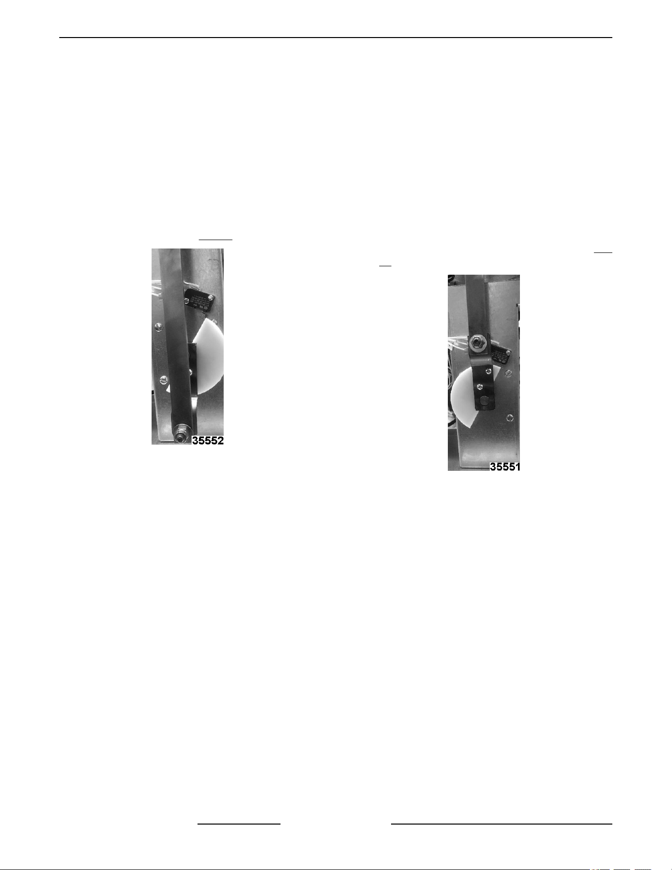
B. 24VDC output from P11 on controller to P1
on interface board (right timer-from P10 on
controller to P2 on interface board)
C. Interface board supplies 24VAC out from P9
to the left basket lift relay coil. (right timer-
from P8 to right basket lift relay).
D. The basket relay contacts close and supply
power out terminal 3 to the basket motor via
the NO circuit of the basket switch.
3. The basket motor turns, lowering the basket arm
until the basket cam moves off the basket switch
to open the NO circuit. (Fig. 75)
Fig. 75
A. The NC circuit is made on the basket switch,
power is removed from the motor and it
stops.
4. The controller timer reaches 0 and begins to
alarm.
A. The 24VDC output from P11 on controller to
P1 on interface board is removed. (right
timer-from P10 on controller to P2 on
interface board).
B. The 24VAC out from P9 of the interface
board to the left basket lift relay coil is
removed. (right timer – from P8 to right
basket lift relay).
C. The basket relay contacts open and the
120VAC power supply switches from
terminal 3 to terminal 1 on the relay.
D. Power is supplied to the basket motor via
terminal 1 of the relay and the NC circuit of
the basket switch.
5. The basket motor turns, raising the basket arm
until the basket cam trips the basket switch to
open the NC circuit and close the NO circuit. (Fig.
76)
Fig. 76
6. The timer button is pressed to silence the alarm
and reset the process.
VK and TR GAS FRYERS W/Wo KleenScreen PLUS - ELECTRICAL OPERATION
F45474 Rev. D (0822) Page 52 of 64
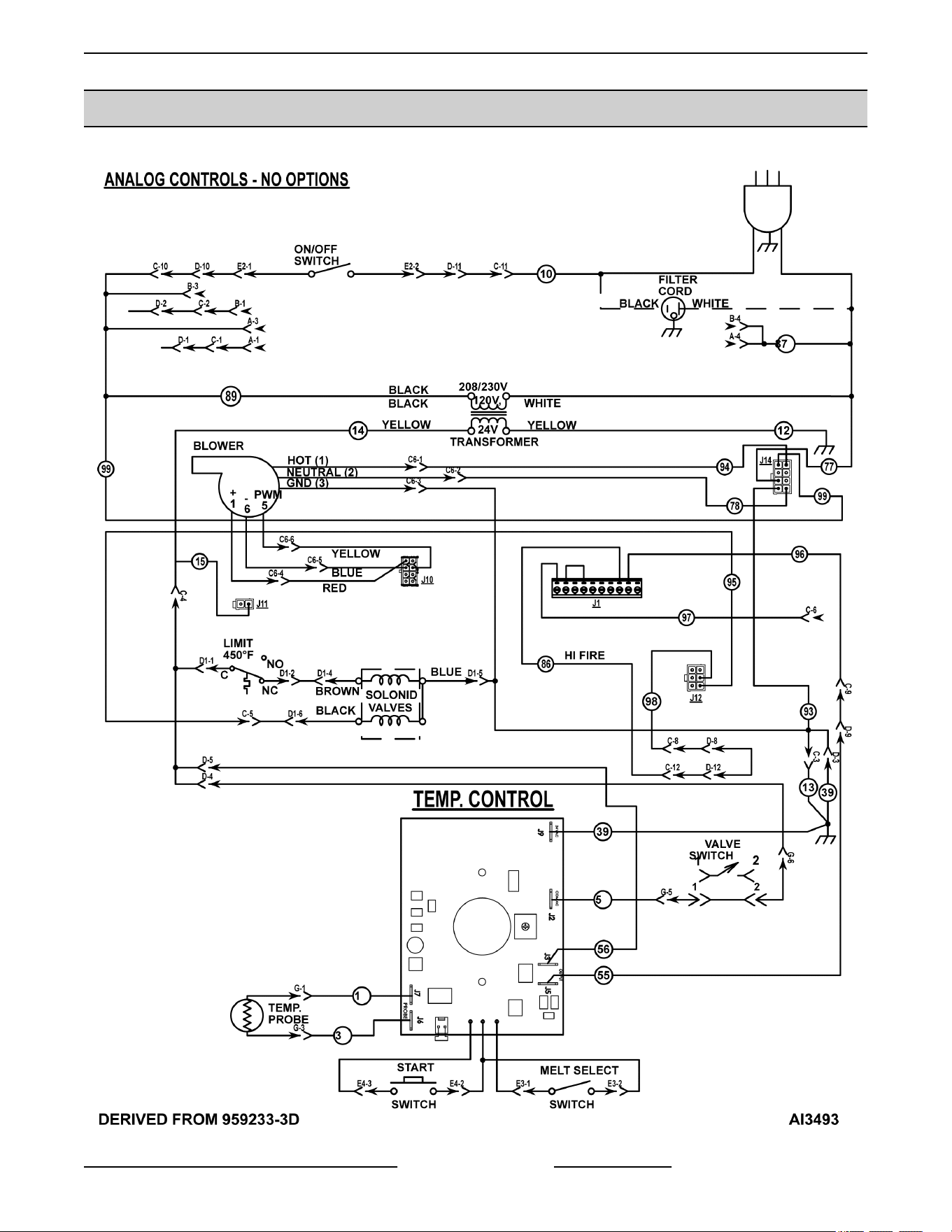
SCHEMATIC DIAGRAMS
Analog Controls - No Options
VK and TR GAS FRYERS W/Wo KleenScreen PLUS - ELECTRICAL OPERATION
Page 53 of 64 F45474 Rev. D (0822)
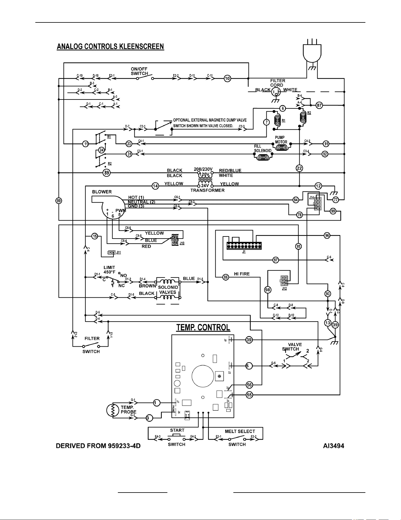
Analog Controls - Kleenscreen
VK and TR GAS FRYERS W/Wo KleenScreen PLUS - ELECTRICAL OPERATION
F45474 Rev. D (0822) Page 54 of 64
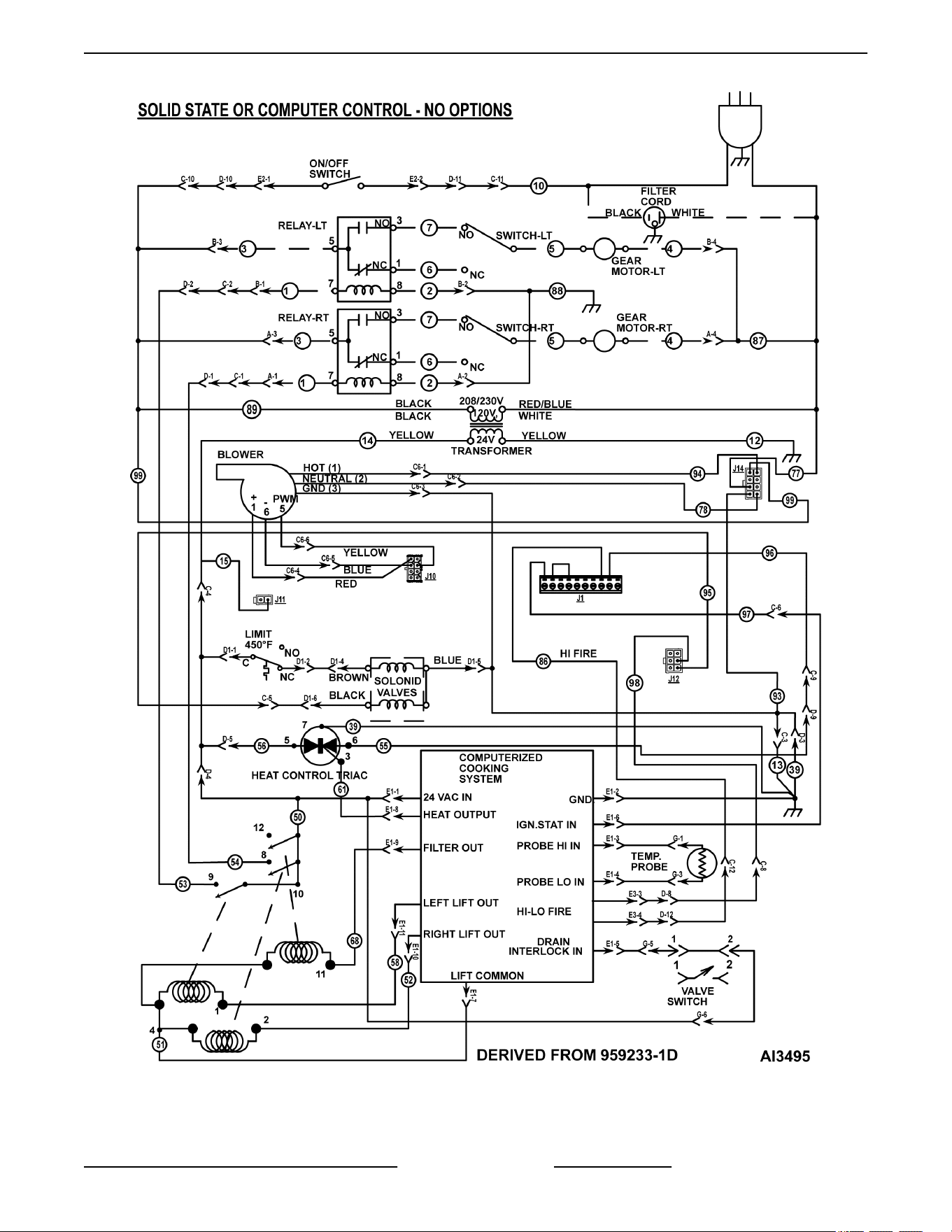
Solid State or Computer Control - No Options
VK and TR GAS FRYERS W/Wo KleenScreen PLUS - ELECTRICAL OPERATION
Page 55 of 64 F45474 Rev. D (0822)
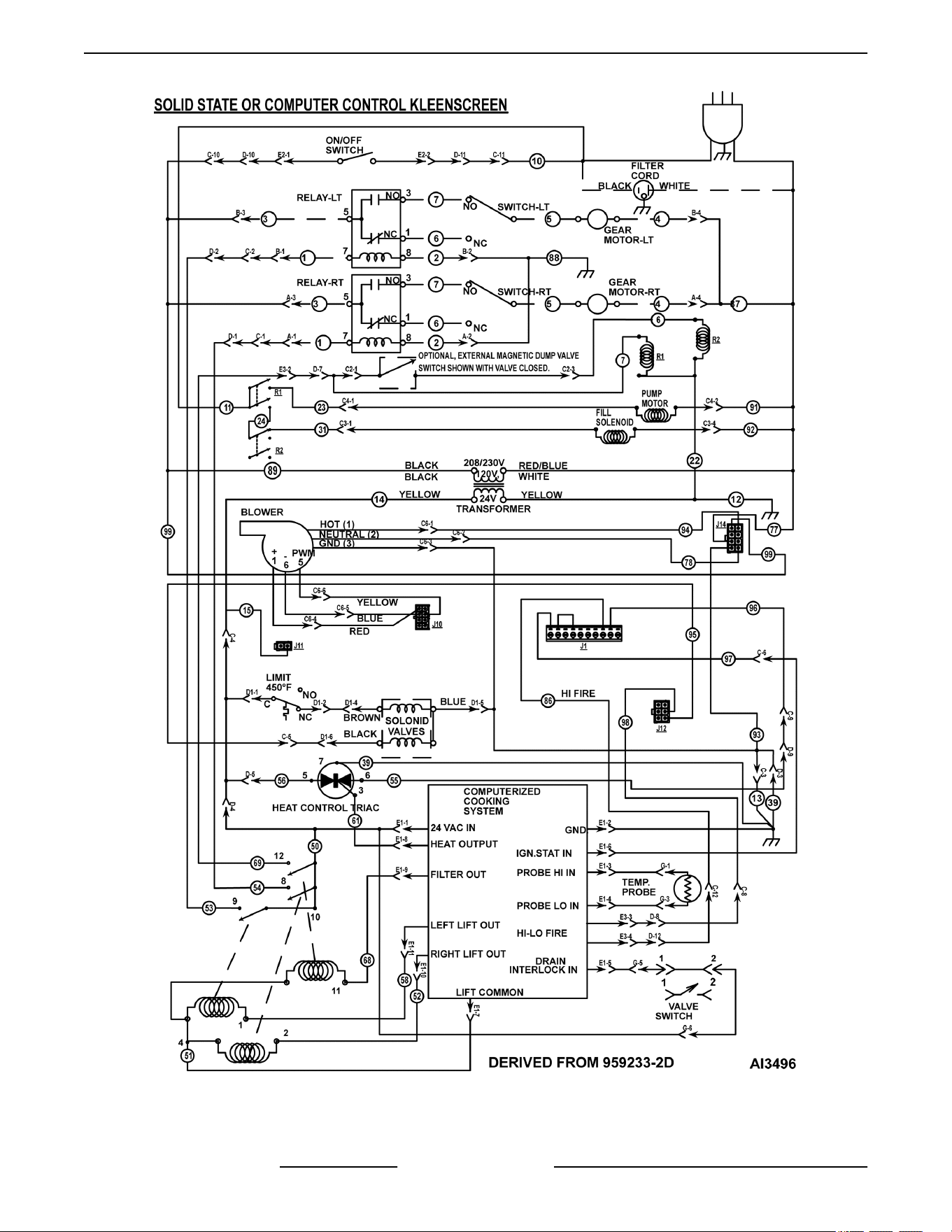
Solid State of Computer Control - Kleenscreen
VK and TR GAS FRYERS W/Wo KleenScreen PLUS - ELECTRICAL OPERATION
F45474 Rev. D (0822) Page 56 of 64
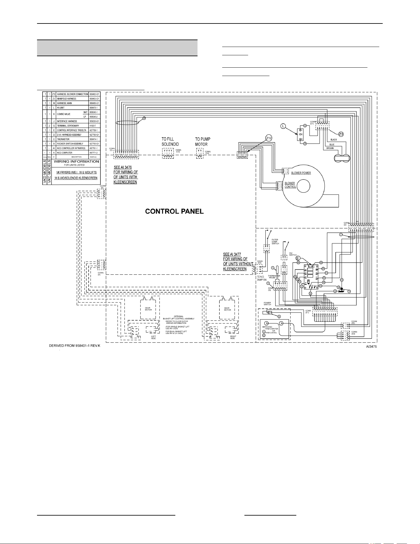
WIRING DIAGRAMS
Diagram LINKS below for Power Box Wiring for Units
Built after December 2012
VK/TR D & C Fryer Wiring Diagram
VK/TR Analog Control W/ Kleenscreen Fryer Wiring
Diagram
VK/TR Analog Control W/E.I. Stand Alone Fryer
Wiring Diagram
VK Fryer (C and D Models)
VK and TR GAS FRYERS W/Wo KleenScreen PLUS - ELECTRICAL OPERATION
Page 57 of 64 F45474 Rev. D (0822)
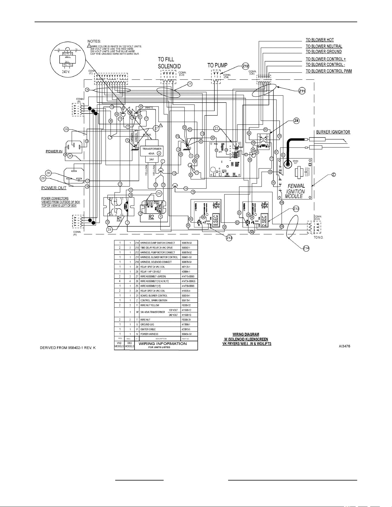
Power Supply Box (Before 12/1/12) - VK Fryer with basket lifts and Kleenscreen
VK and TR GAS FRYERS W/Wo KleenScreen PLUS - ELECTRICAL OPERATION
F45474 Rev. D (0822) Page 58 of 64
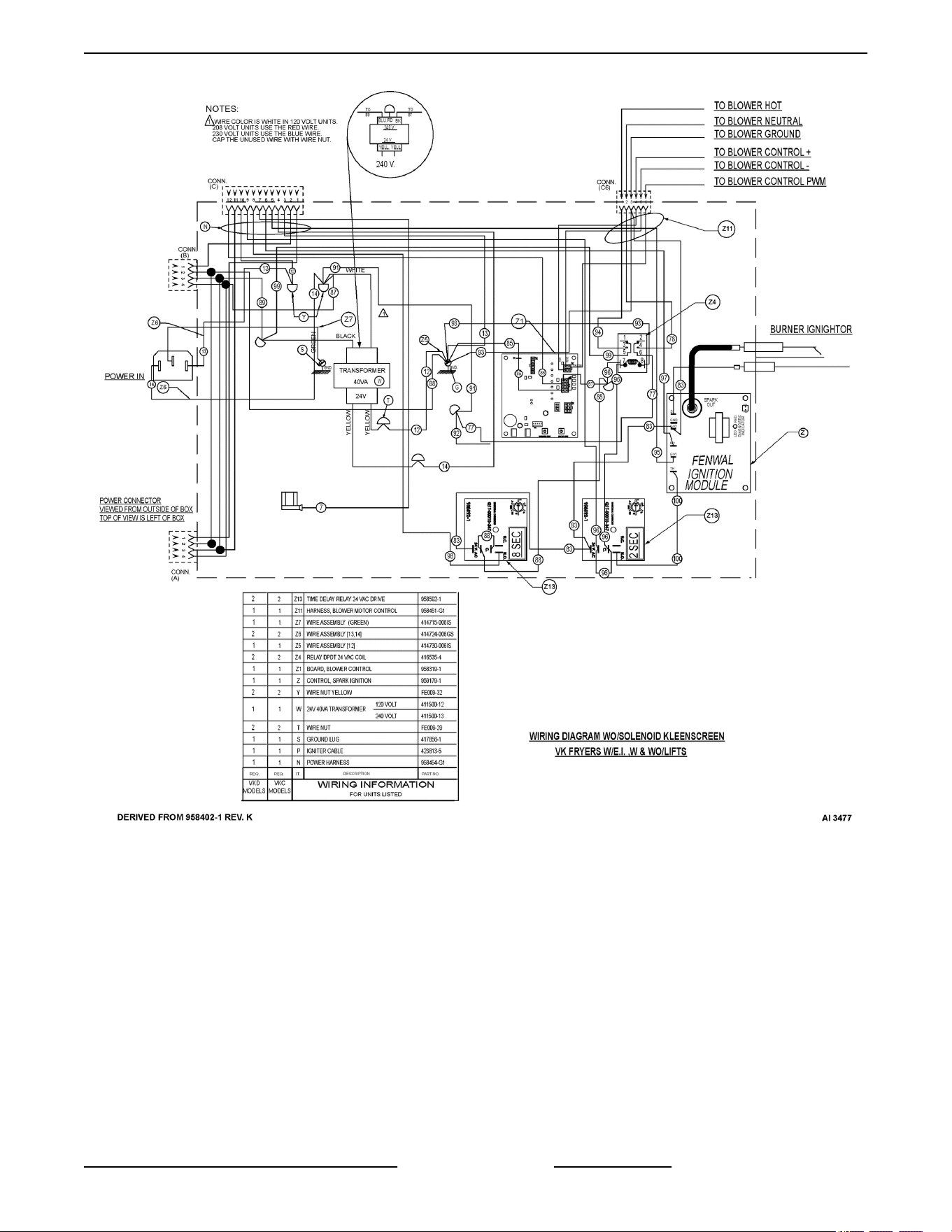
Power Supply Box (Before 12/1/12) - VK Fryer without basket lifts and Kleenscreen
VK and TR GAS FRYERS W/Wo KleenScreen PLUS - ELECTRICAL OPERATION
Page 59 of 64 F45474 Rev. D (0822)
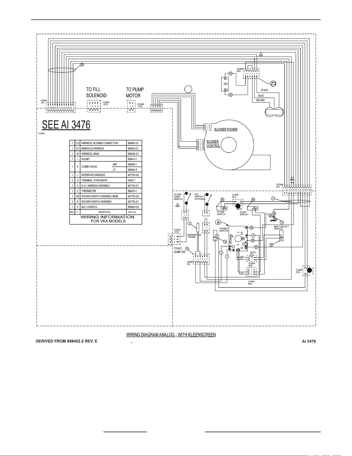
VK Fryers with Electronic Ignition and Analog Control and Kleenscreen
VK and TR GAS FRYERS W/Wo KleenScreen PLUS - ELECTRICAL OPERATION
F45474 Rev. D (0822) Page 60 of 64
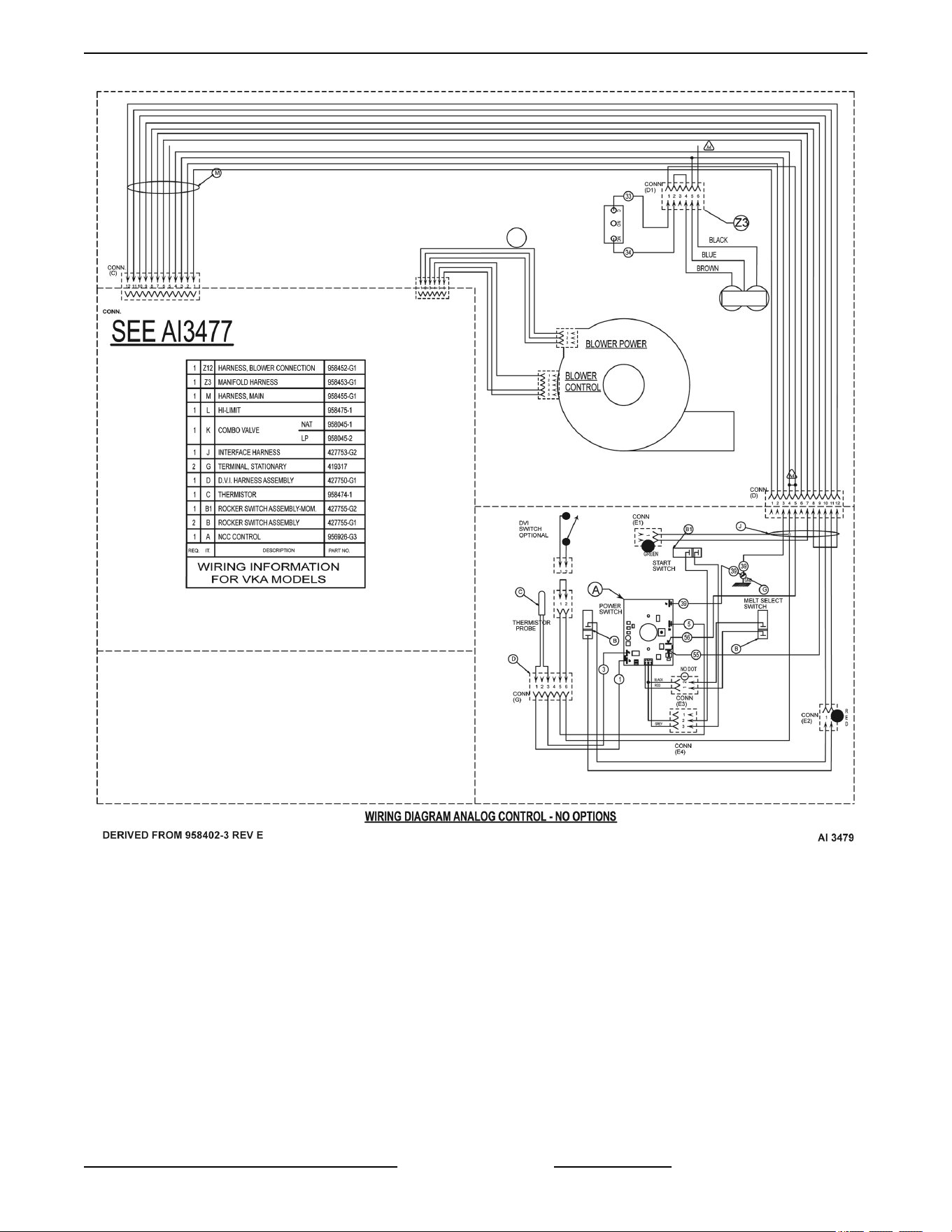
VK Fryers with Electronic Ignition and Analog Control
VK and TR GAS FRYERS W/Wo KleenScreen PLUS - ELECTRICAL OPERATION
Page 61 of 64 F45474 Rev. D (0822)
TROUBLESHOOTING
TROUBLESHOOTING
ALL MODELS
SYMPTOMS POSSIBLE CAUSES
Ignition lockout, continuous loud beep
1. Harness connection to gas valve.
2. Gas valve or gas pressure.
3. Air filter.
4. All harness connections.
5. Electrode.
6. Drain valve switch open or switch malfunction.
7. Interconnecting wiring malfunction.
8. Ignition module malfunction.
9. High limit or thermostat open.
10. Vent hose closed off or restricted.
Initial beep then shut off
1. Grounding status.
2. Check electrode.
No spark no blower
1. Harness connections (check for flashing light in A
control).
2. Probe lead wires.
3. Open probe.
4. Controller.
5. Open fuse on ignition/blower control board
"Puffing" during initial start up
1. Air Filter dirty.
2. Incorrect gas pressure.
3. Vent hose closed off or restricted.
4. Cracked electrode.
5. Incorrect electrode gap.
Burner lights but will not maintain flame
1. Igniter/flame sense misaligned.
2. Insufficient gas pressure.
3. Incorrect polarity from transformer to ignition
module.
4. Incorrect electrode gap.
VK and TR GAS FRYERS W/Wo KleenScreen PLUS - TROUBLESHOOTING
F45474 Rev. D (0822) Page 62 of 64
ALL MODELS
SYMPTOMS POSSIBLE CAUSES
Excessive heat
1. Incorrect temperature offset selected.
2. Set temperature exceeding 400°F.
3. Temperature probe malfunction.
4. Cooking control malfunction.
5. Interface board malfunction.
6. Gas pressure incorrect.
Low heat
1. Incorrect temperature offset selected.
2. Cooking control malfunction.
3. Temperature probe malfunction.
4. High limit tripped.
5. Interface board malfunction.
6. Gas pressure incorrect.
Intermittent problems
1. High ambient temperatures.
2. Wiring connections loose.
No power to cooking control, fryer does not heat
1. Power switch off or malfunction.
2. Main circuit breaker off.
3. Transformer inoperative.
4. Interconnecting wiring malfunction.
High limit thermostat shutting down system
1. Shortening level below minimum fill line.
2. Probe malfunction.
3. Control malfunction.
Excessive time to melt shortening (more than 45 minutes)
1. Melt cycle timing incorrect.
2. Insufficient gas pressure.
3. Air inlet obstructed or incorrect.
4. Probe malfunction.
5. Control malfunction.
Dry fire fry tank
1. Magnets on drain valve (DVI switch) not aligned
properly.
2. Control malfunction.
3. Probe malfunction.
INTERFACE CONTROL BOARD PIN-OUTS
VK and TR GAS FRYERS W/Wo KleenScreen PLUS - TROUBLESHOOTING
Page 63 of 64 F45474 Rev. D (0822)
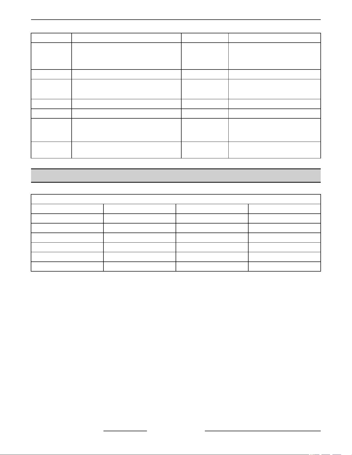
PIN NO. INPUTS PIN NO. OUTPUTS
P1 24VDC Left Basket Lift P6
Heat Demand, Triac (24VAC)
NOTE: To J1-2 terminal of blower/
ignition control board.
P2 24VDC Right Basket Lift P7 System Ground
P3 24VDC Heat Demand Control P8
24VAC Right Basket Lift
NOTE: To basket lift relay coil.
P4 DC (-) Common P9 24VAC Left Basket Lift
P5 Heat Demand, Triac (24VAC) --- ---
P10
Heat Status (24VAC)
NOTE: Relays connected internally.
P12
24 VAC to the filter pump and
external magnetic dump valve
switch.
P11
24 VDC from the computer to the interface
board for the filter pump.
--- ---
D AND C COOKING CONTROL PIN IN-OUTS
12-PIN CONNECTOR
PIN NO. INPUTS PIN NO. OUTPUTS
P1 24 VAC Power Supply P7 24 VDC Common
P2 24 VAC Neutral P8 24VDC Heat Demand
P3 Thermistor Probe Ω P9 24VDC Filter Demand
P4 Thermistor Probe Ω P10 24VDC Right Basket Lift
P5 24 VAC Drain Status P11 24VDC Left Basket Lift
P6 24 VAC Ignition Status P12 No Connection
VK and TR GAS FRYERS W/Wo KleenScreen PLUS - TROUBLESHOOTING
F45474 Rev. D (0822) Page 64 of 64