Installation & Service Manual
Models: 497 - 2067
Save this manual for future reference.
CBX-CWX-I-S_100160893_2000001309_Rev X
This manual supplies information for the
installation, operation, and servicing of the
appliance. It is strongly recommended that this
manual be reviewed completely before proceeding
with an installation. Perform steps in the order
given. Failure to comply could result in severe
personal injury, death, or substantial property
damage.
⚠ WARNING:
-- This water heater MUST NOT be installed
in any location where gasoline or flammable
vapors are likely to be present.
-- WHAT TO DO IF YOU SMELL GAS
• Do not try to light any appliance.
• Do not touch any electric switch; do not
use any phone in your building.
• Immediately call your gas supplier from a
near by phone. Follow the gas supplier’s
instructions.
• If you cannot reach your gas supplier, call
the fire department.
• Installation and service must be performed
by a qualified installer, service agency, or
the gas supplier.
⚠ WARNING: If the information in
this manual is not followed exactly, a fire
or explosion may result causing property
damage, personal injury or loss of life.

Contents
Hazard definitions
The following defined terms are used throughout this manual to bring attention to the presence of hazards of various risk
levels or to important information concerning the life of the product.
⚠ DANGER
⚠ WARNING
⚠ CAUTION
CAUTION
NOTICE
DANGER indicates an imminently hazardous situation which, if not avoided, will result in death or
serious injury.
WARNING indicates a potentially hazardous situation which, if not avoided, could result in death or
serious injury.
CAUTION indicates a potentially hazardous situation which, if not avoided, may result in minor or
moderate injury.
CAUTION used without the safety alert symbol indicates a potentially hazardous situation which, if not
avoided, may result in property damage.
NOTICE indicates special instructions on installation, operation, or maintenance that are important but
not related to personal injury or property damage.
2
HAZARD DEFINITIONS ................................................... 2
PLEASE READ BEFORE PROCEEDING ................... 3-4
SAFETY INFORMATION ................................................. 4
THE COPPER-FIN -- HOW IT WORKS ....................... 5-7
RATINGS........................................................................ 8-9
1. DETERMINE UNIT LOCATION
Locating the Unit .............................................................. 10
Indoor Clearances from Combustible Construction ........ 10
Freeze Protection ........................................................ 11-12
Prevent Combustion Air Contamination ...................... 11-13
Combustion Air Options .............................................. 14-15
2. VENTING
General Venting Information ....................................... 16-17
Vent System Options
Conventional Negative Draft Venting .................... 18-21
Masonry Chimney Installation and Inspection ............ 19
Outdoor Installation Options .................................. 22-23
3. GAS CONNECTIONS
Connecting to Gas Supply ............................................... 24
Gas Pressure Test ........................................................... 24
Gas Piping ........................................................................ 24
Gas Connections / Gas Train and Controls ..................... 25
Combination Gas Valves .................................................. 26
Checking Gas Supply Pressure .................................. 26-27
Gas Manifold Pressure Adjustment ............................ 27-28
4. WATER CONNECTIONS
Inlet & Outlet Connections ............................................... 29
Relief Valve ...................................................................... 29
Heating Boiler Installations .......................................... 29-31
Low Temperature Return Water Systems ........................ 32
Primary/Secondary Piping of a Single Boiler .............. 33
Primary/Secondary Piping of Multiple Boilers ............ 34
Boiler w/Low Temperature Bypass Piping .................. 35
Primary/Secondary Piping with Buffer Tank ............... 36
Installation with a Chilled Water System .......................... 37
Typical Heating Boiler Installations .................................. 37
Boiler Flow Rate / Bypass Requirements ................... 37-38
Temperature/Pressure Gauge and Water Treatment ...... 38
5. ELECTRICAL CONNECTIONS
Connecting to Electrical Supply ....................................... 39
Line Voltage Connections ........................................... 40
EMS Connections ............................................................ 40
Terminal Strip Connection Options ............................. 40-41
Temperature Controls
Temperature Adjustment ............................................ 41
Outdoor Reset Option ................................................. 42
Temperature Control Sensors ............................... 43-44
Hot Surface Ignition System ............................................ 45
Operation and Diagnostic Lights ...................................... 46
6. STARTUP
Operating and Safety Instructions .................................... 47
Check Water Chemistry ................................................... 48
Freeze Protection (when used) ........................................ 48
Fill and Test Water System .............................................. 49
Purge Air from Water System .......................................... 49
Check for Gas Leaks / Thermostat Circuit(s) ................... 50
Check Vent and Air Piping ............................................... 50
Placing the Boiler in Operation ........................................ 50
7. DOMESTIC WATER HEATERS
General ............................................................................. 51
Water Velocity Control ..................................................... 51
Pipe Size Requirements
Typical Water Heater Piping w/ Storage Tank ........... 52
Single Water Heater Piping w/Two Storage Tanks ... 53
Multiple Water Heater Piping w/One Storage Tank ... 54
Multiple Water Heater Piping w/Multi. Storage Tanks . 55
Water Chemistry............................................................... 56
Circulating Pump/ Performance ....................................... 56
Heat Exchanger ............................................................... 57
Potable Hot Water Temperature Controls ........................ 57
Location of Cold Water Supply Piping Connections ........ 58
High Water Temperature Limit Control ............................ 59
Optional Relief Valve ........................................................ 59
Thermal Expansion and Cathodic Protection ................... 59
8. MAINTENANCE
Burner Flames .................................................................. 60
Burner Removal and Cleaning Procedures ................ 60-61
Adjusting Differential Air Pressure .............................. 61-62
Servicing a Hot Surface Igniter / Ignition Module ............ 63
Sequence of Operation Overview ............................... 63-64
9. GLOSSARY & NOTES .......................................... 65-67
10. DIAGRAMS ........................................................... 68-71
Revision Notes .................................................. Back Cover
Installation & Service Manual
33
Please read before proceeding
NOTICE
This is a gas appliance and should be installed
by a licensed electrician and/or certified gas
⚠ WARNING
If the information in these instructions is
not followed exactly, a fire or explosion may
Warranty –
Factory warranty (shipped with unit) does not apply to units
improperly installed or improperly operated.
Experience has shown that improper installation or system
design, rather than faulty equipment, is the cause of most
operating problems.
1. Excessive water hardness causing a lime/scale build-up in
the copper tube is not the fault of the equipment and is
not covered under the manufacturer’s warranty (see
Water Treatment and Water Chemistry).
2. Excessive pitting and erosion on the inside of the copper
tube may be caused by too much water velocity through
the tubes and is not covered by the manufacturer’s
warranty (see Boiler Flow Rates and Temperature Rise for
flow requirements).
Checking equipment –
Upon receiving equipment, check for signs of shipping damage.
Pay particular attention to parts accompanying the appliances
which may show signs of being hit or otherwise being
mishandled. Verify total number of pieces shown on packing
slip with those actually received. In case there is damage or a
shortage, immediately notify the carrier.
Do not use this appliance if any part has been under water.
The possible damage to a flooded appliance can be extensive
and present numerous safety hazards. Any appliance that
has been under water must be replaced.
The installer must verify that at least one carbon monoxide
alarm has been installed within a residential living space or home
following the alarm manufacturer's instructions and applicable
local codes before putting the appliance into operation.
⚠ WARNING
Improper installation, adjustment,
alteration, service or maintenance can cause
Special instructions
REMOVAL OF COMBUSTION CHAMBER LINING OR
BASE PANELS:
¢ Avoid breathing dust and contact with skin
and eyes.
• Use NIOSH certified dust respirator (N95).
This type of respirator is based on the OSHA
requirements for cristobalite at the time this
document was written. Other types of
respirators may be needed depending on the job
site conditions. Current NIOSH recommendations
can be found on the NIOSH website at
http://www.cdc.gov/niosh/homepage.html.
NIOSH approved respirators, manufacturers, and
phone numbers are also listed on this website.
The ceramic fiber material used in this
appliance is an irritant; when handling or
NOTICE
⚠ WARNING
The combustion chamber insulation in this
appliance contains ceramic fiber material.
¢ Apply enough water to the combustion chamber
lining to prevent airborne dust.
¢ Remove the combustion chamber lining from the
appliance and place it in a plastic bag for disposal.
• NIOSH stated First Aid:
Eye: Irrigate immediately.
Breathing: Fresh air.
Ceramic fibers can be converted to cristobalite in very high
temperature applications. The International Agency for
Research on Cancer (IARC) has concluded, “Crystalline silica
in the form of quartz or cristobalite from occupational sources
is carcinogenic to humans (Group 1).” Normal operating
temperatures in this appliance are below the level to convert
ceramic fibers to cristobalite. Abnormal operating conditions
would have to be created to convert the ceramic fibers in this
appliance to cristobalite.
The ceramic fiber material used in this appliance is an irritant;
when handling or replacing the ceramic materials it is advisable
that the installer follow these safety guidelines.
supplier. Service must be performed by a qualified service
installer, service agency or the gas supplier.
result causing property damage, personal injury, or death.
This appliance MUST NOT be installed in any location where
gasoline or flammable vapors are likely to be present, unless the
installation is such to eliminate the probable ignition of gasoline
or flammable vapors.
injury or property damage. Refer to this manual for assistance
or additional information, consult a qualified installer, service
agency or the gas supplier.
replacing the ceramic materials it is advisable that the installer
follow these safety guides.
• Wear long-sleeved, loose fitting clothing, gloves,
and eye protection.
4
Please read before proceeding
Codes –
The equipment shall be installed in accordance with those
installation regulations in force in the local area where the
installation is to be made. These shall be carefully followed in all
cases. Authorities having jurisdiction shall be consulted before
installations are made. In the absence of such requirements, the
installation shall conform to the latest edition of the National
Fuel Gas Code, ANSI Z223.1. Where required by the authority
having jurisdiction, the installation must conform to American
Society of Mechanical Engineers Safety Code for Controls and
Safety Devices for Automatically Fired Boilers, ASME CSD-1.
All boilers conform to the latest edition of the ASME Boiler
and Pressure Vessel Code, Section IV. Where required by the
authority having jurisdiction, the installation must comply with
the Canadian Gas Association Code, CAN/CGA-B149.1 and/
or B149.2 and/or local codes. This appliance meets the safe
lighting performance criteria with the gas manifold and control
assembly provided, as specified in the ANSI standards for gas-
fired hot water boilers, ANSI Z21.13 and gas water heaters,
ANSI Z21.10.3.
⚠ Owner warning –
The information contained in this manual is intended for use
by qualified professional installers, service technicians, or gas
suppliers.
NOTICE
Consult and follow all local Building and
Fire Regulations and other Safety Codes that
apply to this installation. Consult local gas
utility company to authorize and inspect all
gas and flue connections.
A gas appliance that draws combustion air from the equipment
room where it is installed must have a supply of fresh air
circulating around it during burner operation for proper gas
combustion and proper venting.
⚠ WARNING
Should overheating occur or the gas supply
fail to shut off, do not turn off or disconnect
the electrical supply to the pump. Instead,
shut off the gas supply at a location external
to the appliance.
Safety information
1. This unit is only for use with the type of gas indicated on the
rating plate.
2. If you smell gas
• shut off gas supply
• do not try to light any appliance
• do not touch any electrical switch; do not use any phone
in your building
• immediately call your gas supplier from a neighbor’s
phone. Follow the gas supplier’s instructions
• if you cannot reach your gas supplier, call the fire
department
3. Boilers and water heaters are heat producing appliances. To
avoid damage or injury, do not store materials against the
appliance or the vent-air intake system. Use proper care
to avoid unnecessary contact (especially children) with the
appliance and vent-air intake components.
4. Never cover your unit, lean anything against it, store trash
or debris near it, stand on it or in any way block the flow of
fresh air to your unit.
5. UNDER NO CIRCUMSTANCES MUST FLAMMABLE
MATERIALS SUCH AS GASOLINE OR PAINT THINNER
BE USED OR STORED IN THE VICINITY OF THIS
APPLIANCE, VENT-AIR INTAKE SYSTEM OR ANY
LOCATION FROM WHICH FUMES COULD REACH
THE APPLIANCE OR VENT-AIR INTAKE SYSTEM.
6. Appliance surfaces become hot during operation. Be careful
not to touch hot surfaces. Keep all adults, children, and
animals away from operation of the hot unit. Severe burns
can occur.
7. You must take adequate care to prevent scald injury when
storing water at elevated temperatures for domestic use.
8. This unit must have an adequate supply of fresh air during
operation for proper gas combustion and venting.
9. Make sure all exhaust venting is properly installed and
maintained. Improper venting of this unit could lead to
increased levels of carbon monoxide.
10. Do not use this boiler if any part has been under water.
Immediately call a qualified service technician to replace
the boiler. The possible damage to a flooded boiler can
be extensive and present numerous safety hazards. Any
appliance that has been under water must be replaced.
11. Do not alter this unit in any way. Any change to this unit or
its controls can be dangerous.
⚠ WARNING
To minimize the possibility of serious
personal injury, fire or damage to your
unit, never violate the following safety
rules.
Installation & Service Manual
Boiler water –
• Thoroughly flush the system to remove debris. Use
an approved pre-commissioning cleaner (see Start-Up
Section), without the boiler connected, to clean the system
and remove sediment. The high-efficiency heat exchanger
can be damaged by build-up or corrosion due to sediment.
NOTE: Cleaners are designed for either new systems or
pre-existing systems. Choose accordingly.
Freeze protection fluids –
• NEVER use automotive antifreeze. Use only inhibited
propylene glycol solutions, which are specifically
formulated for hydronic systems. Ethylene glycol is
toxic and can attack gaskets and seals used in hydronic
systems.

5
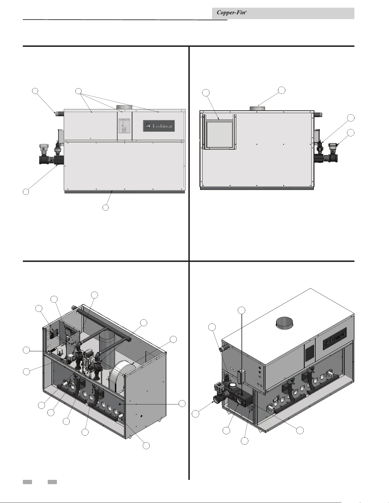
The Copper-fin - How it works...
1. Heat exchanger
The heat exchanger allows system water to flow through specially
designed tubes for maximum heat transfer. The glass lined
headers and copper fined tubing are encased in a jacket that
contains the combustion process.
2. Inner combustion chamber door
The inner combustion chamber door is a galvanized steel door which
allows access for service, maintenance, and removal of the
heat exchanger from inside the combustion chamber.
3. Blower
The blower pulls in air and injects air into the individual burners
along with gas from the gas manifold where the mix is burned in
the combustion chamber.
4. Gas valve
The gas valve allows the proper amount of gas to pass into the
burner for combustion. The gas valve is biased with pressure from
the combustion chamber to assist in regulation of the gas flow.
5. System / tank temperature sensor (not shown)
When connected, this sensor can be used as a system sensor or a
tank sensor.
6. Inlet temperature sensor
This sensor monitors inlet water temperature. If selected as
the controlling sensor, the appliance will maintain the set point
temperature based on the reading at this sensor.
7. Temperature and pressure gauge (boiler only)
The temperature and pressure gauge monitors the outlet
temperature of the appliance as well as the system water
pressure.
8. Diagnostic display
The diagnostic display consists of six (6) lamps used to show all
the major steps of operation and control malfunctions.
9. Burner
The burner is a ported stainless steel construction which uses a gas
air mix to operate at a fixed input. Banks of burners are turned on
or off to vary the firing rate.
10. Water outlet (system supply)
The water outlet is a pipe connection that supplies water to the
system with connections for a flow switch (see #25), a relief valve
(see #22), and a temperature and pressure gauge (boilers only)
(see #7).
11. Water inlet (system return)
The water inlet is a pipe connection that receives water from the
system and delivers it to the heat exchanger.
12. Gas supply pipe
The gas supply pipe on this appliance is 1 1/4'' diameter (Models
497 - 747) and 2" diameter (Models 987 - 2067) NPT. Please
reference the National Fuel Gas Code charts for connection
details.
13. Two-Stage Electronic Temperature Control
The electronic temperature control provides two-stage (high / low
fire) operation by monitoring system demand.
14. Air intake
Fresh air for combustion is drawn through a filter provided at the
air intake, located at either the rear or right side of the appliance.
15. Line voltage terminal strip
The line voltage terminal strip provides a location to connect
all of the line voltage (120 VAC) contact points to the unit.
16. Low voltage connection board
The low voltage connection board provides a location to tie in
all of the low voltage contacts to the appliance. This is where most
of the external safety devices are connected to the unit such as
the louver proving switch.
17. Front doors - upper and lower
The front doors provide access to the gas train as well as the
blower, burners and other key components for service and
maintenance.
18. Hot surface igniter (HSI)
The hot surface igniter is a device that is used to ignite the
air/gas mixture as well as monitor the performance of the flame
during operation. This device acts as a flame sense electrode.
19. Flame inspection window (sight glass)
The flame inspection windows, located on either side of the
appliance, allow for visual inspection of the burners and flame
during operation.
20. Gas shut off valve (downstream test cock)
The downstream test cock (when supplied) is in the gas train to ensure
complete shut off of the gas to the burner in case of
maintenance, inspection, or testing of the valve.
21. Manual high limit
Device that monitors the outlet water temperature to ensure
safe operation. If the temperature exceeds its setting (field
adjustable), it will break the control circuit, shutting the
appliance down.
22. Relief valve
The relief valve is a safety device that ensures the maximum
pressure of the appliance is not exceeded. Boilers operate on
pressure only and are shipped from the factory at a rating of
50 PSI. Water heaters operate on temperature and pressure and
are shipped standard as 150 PSI and 210°F (98.9°C).
23. Power switch
The power switch is used to engage and disengage power to the
appliance on the 120 VAC circuit.
24. Air pressure switch
The air pressure switch is a safety device which ensures proper
blower operation. The air pressure switch is wired in series with
the low voltage control circuit in such a way that if the fan does not
engage or shuts down prematurely the device will break the
control circuit and the unit will shut down.
25. Flow switch
The flow switch is a safety device that ensures flow through the
heat exchanger during operation. This appliance is low mass and
should never be operated without flow. The flow switch makes
contact when flow is detected and allows the unit to operate. If
flow is discontinued during operation for any reason the flow
switch will break the control circuit and the unit will shut down.
26. Drain port(s)
Location from which the heat exchanger can be drained.
27. Manual shutoff valve (not shown)
Manual valve used to isolate the unit from the gas supply.
28. Flue pipe
A pipe like enclosure that is placed over an appliance to improve
natural upward convection of heat and thereby increase the
dissipating ability of the appliance.
Installation & Service Manual
6
The Copper-fin - How it works...
26
26
17
17
17
17
12
12
Models 497 - 747 Front View
Models 497 - 747 Left Side (inside unit)
Models 497 - 747 Right Side (inside unit)
Models 497 - 747 Rear View
14
14
22
22
25
25
28
28
13
13
16
16
21
21
15
15
23
23
18
18
20
20
24
24
9
9
2
2
3
3
4
4
8
8
7
7
6
6
19
19
11
11
10
10
1
1
Installation & Service Manual
7
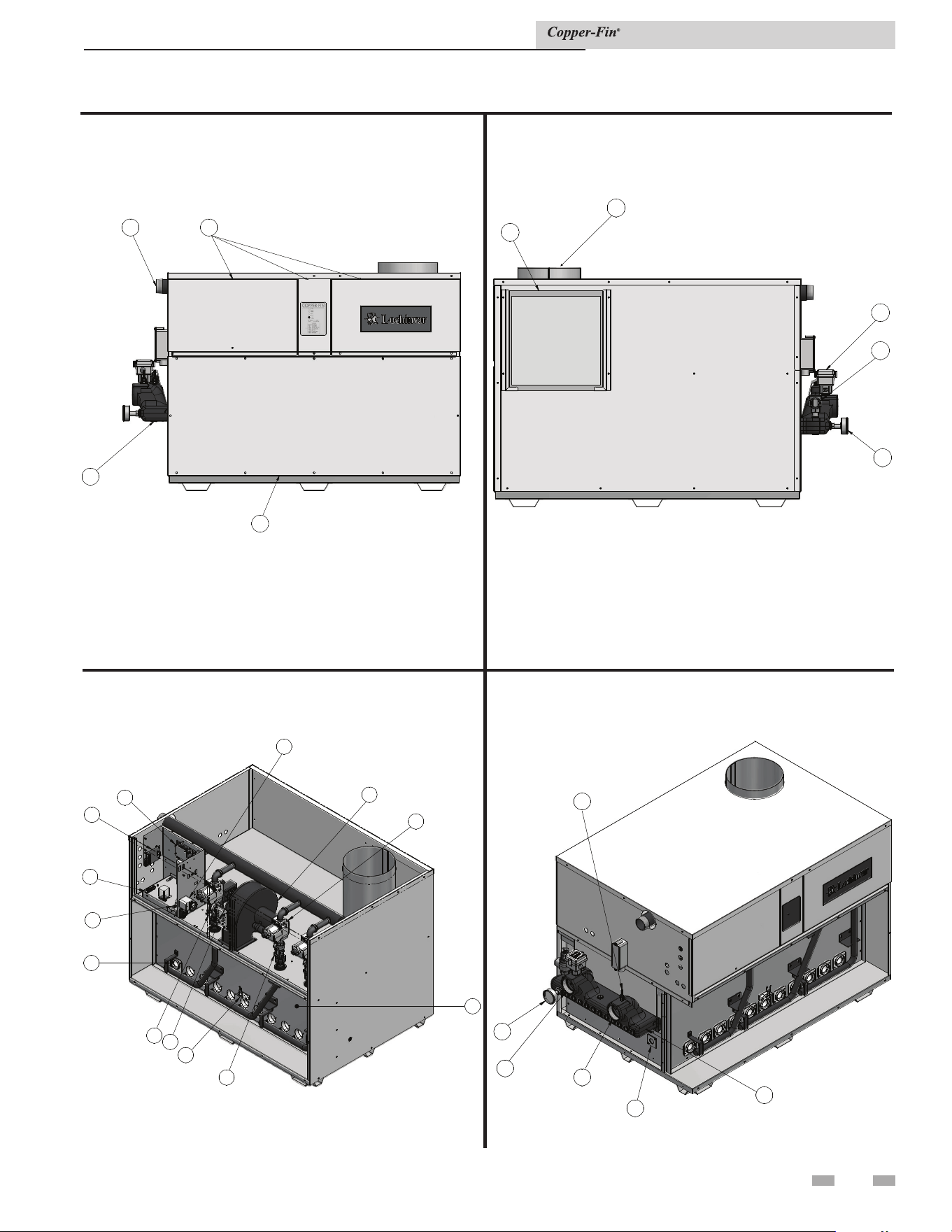
Installation & Service Manual
The Copper-fin - How it works... (continued)
Models 987 - 2067 Left Side (inside unit)
Models 987 - 2067 Right Side (inside unit)
Models 987 - 2067 Rear View
Models 987 - 2067 Front View
14
14
25
25
22
22
7
7
28
28
21
21
4
4
3
3
2
2
9
9
20
20
18
18
24
24
23
23
15
15
16
16
13
13
8
8
6
6
19
19
11
11
10
10
7
7
1
1
12
12
17
17
17
17
26
26
8
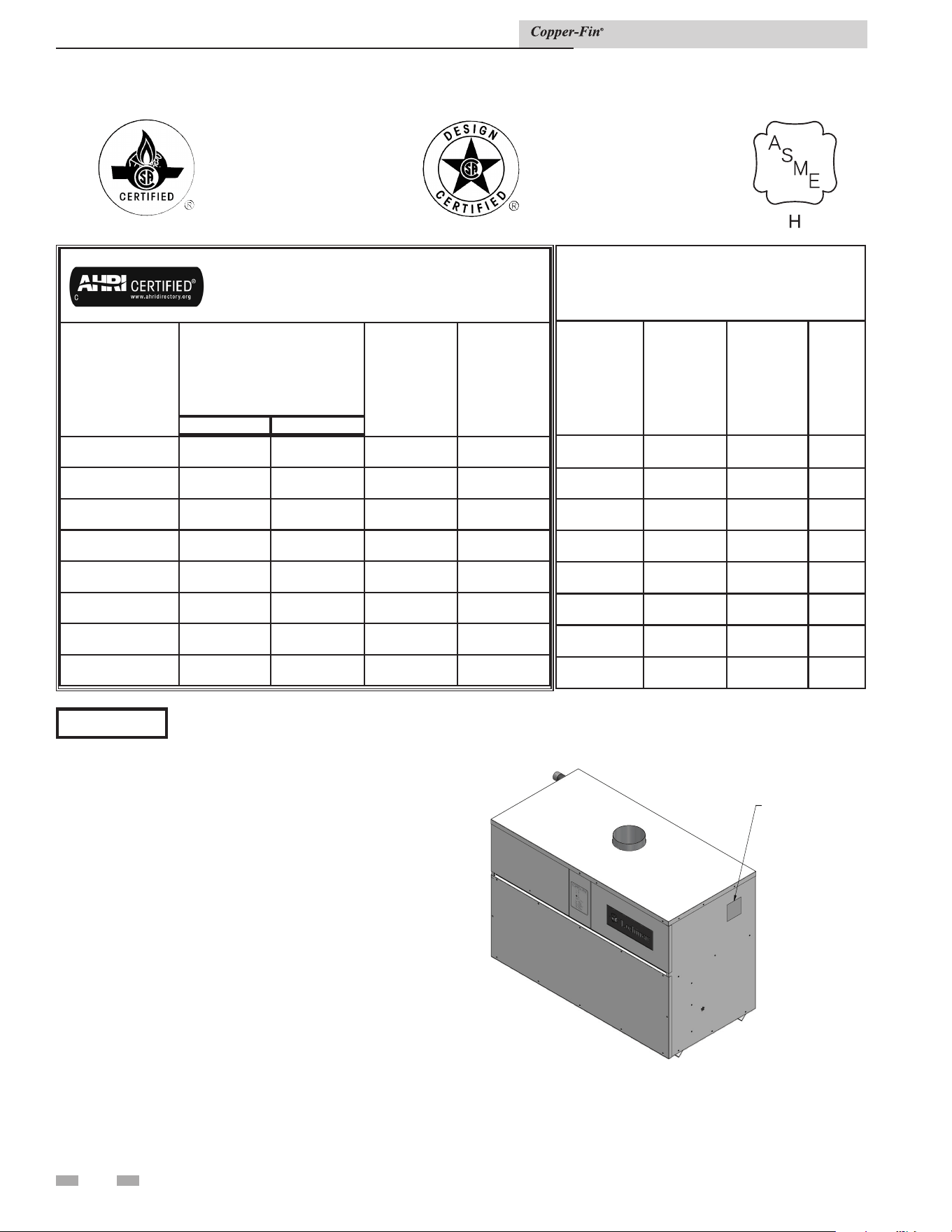
Ratings
Maximum allowed working pressure is located on the rating plate.
NOTICE
Copper-fin
AHRI Rating
Model Number
Note: Change “N” to
“L” for L.P. gas models.
Input MBH
(Note 4)
Min Max
Gross
Output
MBH
(Note 1)
Net
AHRI
Ratings
Water,
MBH
(Note 2)
CBN497 250 495 416 362
CBN647 350 645 542 471
CBN747 350 745 626 544
CBN987 360 985 827 719
CBN1257
720 1255 1054 917
CBN1437
720 1435 1205 1048
CBN1797
720 1795 1508 1311
CBN2067
990 2065 1735 1508
Other Specifications
Boiler Water
Content
Gallons
Water
Connections
Gas
Connections
Vent Size
(Note 3)
1.9 2" 1 1/4" 6"
2.0 2" 1 1/4" 8"
2.4 2" 1 1/4" 8"
3.3 2 1/2" 2" 10"
3.5 2 1/2" 2" 12"
3.7 2 1/2" 2" 12"
4.1 2 1/2" 2" 14"
4.3 2 1/2" 2" 14"
Notes:
1. The ratings are based on standard test procedures
prescribed by the United States Department of Energy.
2. Net AHRI ratings are based on net installed radiation of
sufficient quantity for the requirements of the building
and nothing need be added for normal piping and pickup.
Ratings are based on a piping and pickup allowance of 1.15.
3. Copper-fins require special gas venting. Use only the vent
materials and methods specified in the Installation and
Service Manual.
4. The Copper-fin is orificed for operation up to 2000
feet altitude. The ap pli ance will be derated 4% per 1000
feet above 2000 feet el e va tion. Consult the factory for
installations above 2000 feet elevation.
5. Ratings have been confirmed by AHRI.
Figure A High altitude label location_boiler
H
H
I
I
G
G
H
H
A
A
L
L
T
T
IT
IT
U
U
D
D
E
E
L
L
A
A
B
B
E
E
L
L
Installation & Service Manual
9
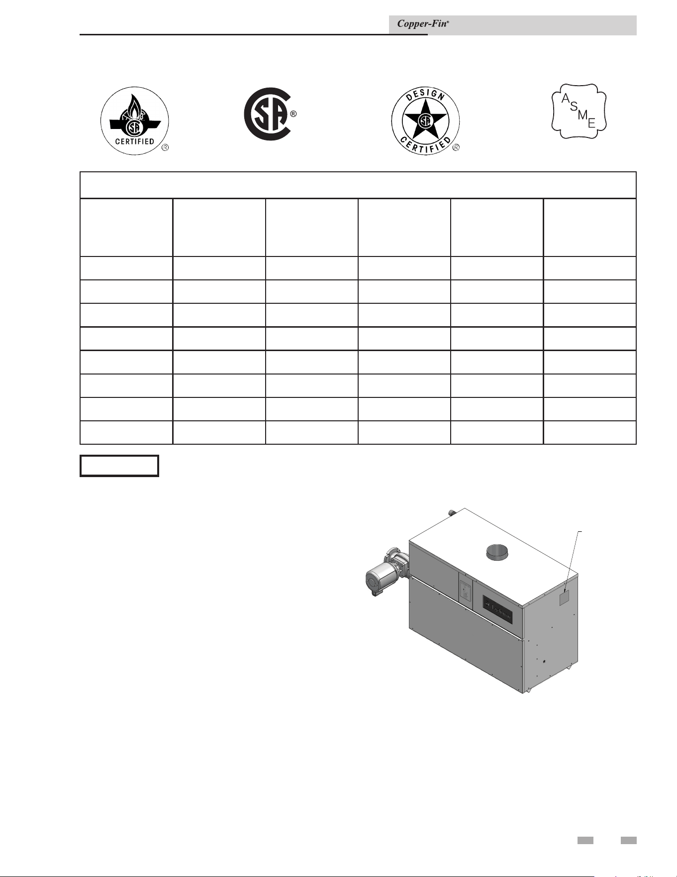
Ratings (continued)
Notes:
1. Copper-fins require special gas venting. Use only
the vent materials and methods specified in the
Installation and Service Manual.
2. The Copper-fin is orificed for operation up to 2000
feet altitude. The ap pli ance will be derated 4% per
1000 feet above 2000 feet el e va tion. Consult the
factory for installations above 2000 feet elevation.
Figure B High altitude label location_water heater
HIGH ALTITU
DE
LABEL
Copper-fin Specifications
Model Number
Note: Change “N” to
“L” for L.P. gas models
Input
MBH
Water
Content Gallons
Water Connections Gas Connections
Vent Size
(Note 1)
CWN497
495 1.9 2" 1 1/4" 6"
CWN647
645 2.0 2" 1 1/4" 8"
CWN747
745 2.4 2" 1 1/4" 8"
CWN987
985 3.3 2 1/2" 2" 10"
CWN1257
1255 3.5 2 1/2" 2" 12"
CWN1437
1435 3.7 2 1/2" 2" 12"
CWN1797
1795 4.1 2 1/2" 2" 14"
CWN2067
2065 4.3 2 1/2" 2" 14"
Maximum allowed working pressure is located on the rating plate.
NOTICE
HLW
Installation & Service Manual
LOW LEAD CONTENT
10
1 Determine unit location
Locating the unit
1. Maintain all clearances from combustible construction
when locating unit. See Clearances from Combustible
Construction, this page.
2. Locate the unit so that if water connections should
leak, water damage will not occur. When such locations
cannot be avoided, install a suitable drain pan that
is well-drained under the unit. The pan must not
restrict combustion air flow. The appliance
manufacturer is not responsible for water damage in
connection with this unit, or any of its components.
3. Install indoor units so that the ignition system
components are protected from any water while
operating or during service.
4. Appliances located in a residential garage and in
adjacent spaces that open to the garage and are not
part of the living space of a dwelling unit must be
installed so that all burners and burner ignition devices
have a minimum clearance of not less
than 18'' (46cm) above the floor. The
appliance must be located or protected so that it is
not subject to physical damage by a moving vehicle.
5. DO NOT install this appliance in any location where
gasoline or flammable vapors are likely to be present.
6. The appliance must be installed on a level surface.
7. Models 497 - 747 are approved for installation on
combustible flooring using the approved combustible floor
kits (reference Table 1A). Models 987 - 2067 are approved
for installation on combustible flooring. Do not install
appliances directly on carpeting.
8. For outdoor models, you must install an optional vent
kit. Instructions for mounting the vent kit are included
in the venting section. Do not install outdoor models
directly on the ground. You must install the outdoor
unit on a concrete, brick, block, or other
non-combustible pad. Outdoor models have additional
special location and clearance requirements. See
Outdoor Installation Venting, page 22. A wind proof
cabinet protects the unit from weather.
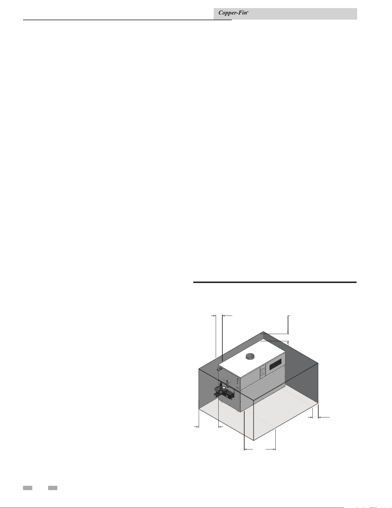
Indoor clearances from combustible
construction
Maintain minimum specified clearances for adequate
operation. Allow sufficient space for servicing pipe
connections, pump and other auxiliary equipment, as well
as the unit. See rating plate for specific service clearance
requirements.
Right Side 3'' (7.5 cm)
Rear 3'' (7.5 cm) (3'' min. from any surface)*
Left Side 6'' (15 cm) (24'' (0.61 m) suggested for
service)
Front Alcove* (30'' (0.76m) suggested for service)
Top 3'' (7.5 cm)
Flue 1'' (25.4 mm)
Hot Water Pipes 1'' (25.4 mm)
*An Alcove is a closet without a door. Thirty-six inches (36")
to rear required for outdoor installation.
Note: No additional clearance is needed on the right side
of the unit for the observation port. An observation port is
located on both the right and left side of the unit.
Figure 1-1_Indoor clearances from combustible
construction
Installation
is unit meets the safe lighting performance criteria with the
gas manifold and control assembly provided, as specied in the
ANSI standards for gas-red units. ANSI Z21.13/CSA 4.9 and
ANSI Z21.10.3/CSA 4.3.
3"
MIN
REAR
3"
MIN
RI
GHT SIDE
30"
MIN
FRONT
3"
MIN
TOP
6"
MIN
LEFT SIDE
Installation & Service Manual
1 Determine unit location (continued)
11
TABLE 1A
COMBUSTIBLE FLOOR KITS
Model Kit Number
497 100136977
647 100136978
747 100136979
⚠ CAUTION
Although these units are CSA International design-
certied for outdoor installations, such installations are not
recommended in areas where the danger of freezing exists. You must
provide proper freeze protection for outdoor installations, units
installed in unheated mechanical rooms or where temperatures
may drop to the freezing point or lower. If freeze protection is
not provided for the system, a low ambient temperature alarm is
recommended for the mechanical room. Damage to the unit by
freezing is non-warrantable.
Anytime the temperature measured at any of the sensors
(except the outside air temperature sensor) drops below 40°F, the
control turns on the pump contact and the alarm relay. e
pump will shut o when both sensors are above 50°F.
Freeze protection
is unit is equipped with a pump delay of 30 seconds. If
continuous operation of the pump is desired, the pump must
be electrically connected to another circuit. Connection of
the pump to this unit will provide intermittent pump delay
operation.
Pump operation
Locate indoor boilers and water heaters in a room having a tem-
perature safely above freezing [32°F (0°C)].
Location
A mechanical room operating under a negative
draft pressure may experience a down draft
in the flue of a boiler when it is not firing.
The cold outside air pulled down the flue
may freeze a heat exchanger. This condition
must be corrected to provide adequate freeze
protection.
Freeze protection for a heating boiler or hot water supply boiler
using an indirect coil can be provided by using hydronic system
antifreeze. Follow the appliance manufacturers instructions. Do
not use undiluted or automotive type antifreeze.
Hydronic systems anti-freeze
Adequate hydronic system antifreeze must be used. A snow
screen should be installed to prevent snow and ice accumulation
around the unit or its venting system.
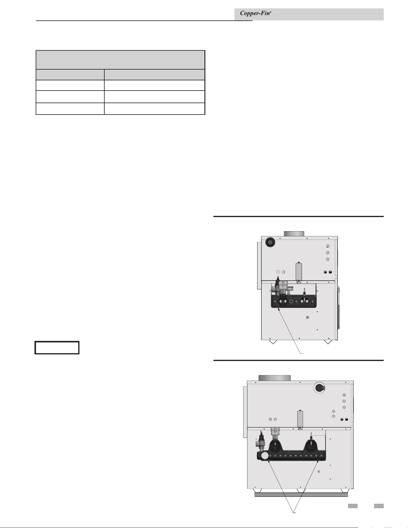
Outdoor boiler installation
If for any reason, the unit is to be shut o, the following
precautionary measures must be taken:
1. Shut o gas supply.
2. Shut o water supply.
3. Shut o electrical supply
4. Drain the unit completely. Remove one threaded plug
or bulbwell from the inlet side of the front header and
one from the outlet side of the front header on the heat
exchanger. Blow all water out of the heat exchanger
(see FIG.'s 1-2A and 1-2B).
5. Drain pump and piping.
Shut-down and draining
DR
DR
A
A
I
I
N
N
P
P
L
L
U
U
G
G
(
(
2
2
X
X
)
)
Figure 1-2B_Drain the unit_Models 987 - 2067
Installation & Service Manual
DRAIN PLUG
Figure 1-2A_Drain the unit_Models 497 - 747
12
1 Determine unit location
TABLE 1B
MINIMUM RECOMMENDED COMBUSTION
AIR SUPPLY TO EQUIPMENT ROOM
Model
Number
*Outside Air from
2 Openings Directly from
Outdoors
*Outside Air from
1 Opening Directly
from Outdoors, in
2
Inside Air from
2 Ducts Delivered from
Outdoors
Inside Air from
2 Ducts Delivered from
Interior Space
Top
Opening, in
2
Bottom
Opening, in
2
Top
Opening, in
2
Bottom
Opening, in
2
Top
Opening, in
2
Bottom
Opening, in
2
497
125
(806 cm
2
)
125
(806 cm
2
)
167
(1077 cm
2
)
250
(1613 cm
2
)
250
(1613 cm
2
)
500
(3226 cm
2
)
500
(3226 cm
2
)
647
163
(1052 cm
2
)
163
(1052 cm
2
)
217
(1400 cm
2
)
325
(2097 cm
2
)
325
(2097 cm
2
)
650
(4194 cm
2
)
650
(4194 cm
2
)
747
188
(1213 cm
2
)
188
(1213 cm
2
)
250
(1613 cm
2
)
375
(2420 cm
2
)
375
(2420 cm
2
)
750
(4839 cm
2
)
750
(4839 cm
2
)
987
248
(1600 cm
2
)
248
(1600 cm
2
)
330
(2129 cm
2
)
495
(3194 cm
2
)
495
(3194 cm
2
)
990
(6388 cm
2
)
990
(6388 cm
2
)
1257
315
(2032 cm
2
)
315
(2032 cm
2
)
420
(2710 cm
2
)
630
(4065 cm
2
)
630
(4065 cm
2
)
1260
(8130 cm
2
)
1260
(8130 cm
2
)
1437
360
(2323 cm
2
)
360
(2323 cm
2
)
480
(3097 cm
2
)
720
(4646 cm
2
)
720
(4646 cm
2
)
1440
(9291 cm
2
)
1440
(9291 cm
2
)
1797
450
(2903 cm
2
)
450
(2903 cm
2
)
600
(3871 cm
2
)
900
(5807 cm
2
)
900
(5807 cm
2
)
1800
(11614 cm
2
)
1800
(11614 cm
2
)
2067
518
(3342 cm
2
)
518
(3342 cm
2
)
690
(4452 cm
2
)
1035
(6678 cm
2
)
1035
(6678 cm
2
)
2070
(13356 cm
2
)
2070
(13356 cm
2
)
*Outside air openings shall directly communicate with the
outdoors. When combustion air is drawn from the outside
through a duct, the net free area of each of the two openings
must have twice (2 times) the free area required for Outside
Air/2 Openings. The above requirements are for the boiler
only; additional gas fired appliances in the equipment room
will require an increase in the net free area to supply adequate
combustion air for all appliances.
1. Use only properly diluted inhibited glycol
anti-freeze designed for hydronic systems. Inhibited
propylene glycol is recommended for systems where
incidental contact with drinking water is possible.
2. A solution of 50% antifreeze will provide
maximum protection of approximately -30°F.
3. Follow the instructions from the antifreeze
manufacturer. Quantity of antifreeze required is
based on total system volume including
expansion tank volume.
4. Glycol is denser than water and changes
the viscosity of the system. e addition
of glycol will decrease heat transfer and
increase frictional loss in the boiler and
related piping. A larger pump with more
capacity (15% to 25% more) may be required
to maintain desired ow rates and
prevent a noise problem in a glycol system.
5. Local codes may require a back ow preventer or
actual disconnect from city water supply when
antifreeze is added to the system.
Freeze Protection for a Heating Boiler
System (if required)
⚠ WARNING
Do not use undiluted or automotive type
anti-freeze.
Combustion and Ventilation Air
Provisions for combustion and ventilation air must be
in accordance with Section 5.3, Air for Combustion and
Ventilation, of the latest edition of the National Fuel Gas Code,
ANSI Z223.1, in Canada, the latest edition of CAN/CGA-B149
Installation Code for Gas Burning Appliances and Equipment,
or applicable provisions of the local building codes.
Provide properly-sized openings to the equipment room to
assure adequate combustion air and proper ventilation when
the unit is installed with conventional venting or sidewall
venting.
Installation & Service Manual
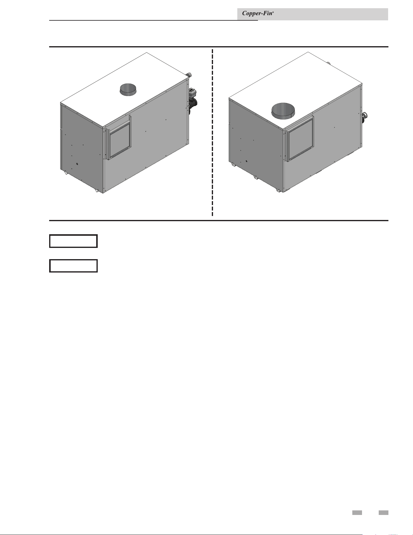
13
Combustion air filter
This unit has a standard air filter located at the combustion air inlet. This filter helps ensure clean air is used for the
combustion process. Check this filter every month and replace when it becomes dirty. The filter size on Models 497 - 747 is
12" x 12" x 1" (30.5cm x 30.5cm x 2.5cm) and 16" x 16" x 1" (40.6cm x 40.6cm x 2.5 cm) on Models 987 - 2067. You can find
these commercially available filters at any home center or HVAC supply store.
Figure 1-3_Combustion air filter_ Models 497 - 747
Figure 1-4_Combustion air filter_ Models 987 - 2067
1 Determine unit location (continued)
CAUTION
During construction the air filter should be checked more frequently to ensure it does not become clogged
with construction dirt and debris.
NOTICE
Sustained operation of an appliance with a clogged burner may result in nuisance operational problems,
bad combustion, and non-warrantable component failures.
Installation & Service Manual
14
1 Determine unit location
This unit has four combustion air options.
1. Outside Combustion Air, No Ducts
You can direct outside combustion air to this unit using either
one or two permanent openings (see FIG. 1-5).
One Opening
The opening must have a minimum free area of one square
inch per 3000 Btu input (7 cm
2
per kW). You must locate this
opening within 12'' (30 cm) of the top of the enclosure.
Combustion Air Options
Under no circumstances should a mechanical
room ever be under a negative pressure.
Particular care should be taken when exhaust
fans, clothes dryers, compressors, air handling
units, etc., take away air from the inlet.
Figure 1-5_Outside combustion air single opening
Two Openings
The combustion air opening must have a minimum free area
of one square inch per 4000 Btu input (5.5cm² per kW). You
must locate this opening within 12'' (30cm) of the bottom of
the enclosure.
The ventilation air opening must have a minimum free area
of one square inch per 4000 Btu input (5.5cm² per kW). You
must locate this opening within 12'' (30cm) of the top of the
enclosure.
Figure 1-6_Outside combustion air, two openings
2. Outside Combustion Air, Using Ducts
You can direct outside combustion air to this unit using two air
ducts to deliver the air to the boiler room.
Each of the two openings must have a minimum free area of one
square inch per 2000 Btu input (11cm² per kW).
Figure 1-7_Outside combustion air, using ducts
⚠ CAUTION
Installation & Service Manual
1 Determine unit location (continued)
15
3. Combustion Air from an Interior Space
You can direct combustion air to this unit using air from an
adjoining interior space. You must provide two openings from
the boiler room to the adjoining room. Each of the two openings
must have a net free area of one square inch per 1000 Btu input
(22cm² per kW), but not less than 100 square inches (645cm²).
Figure 1-8_Combustion air from an interior space
All dimensions are based on net free area in square inches.
Metal louvers or screens reduce the free area of a combustion air
opening a minimum of approximately 25%. Check with louver
manufacturers for exact net free area of louvers. Where two
openings are provided, one must be within 12'' (30 cm) of the
ceiling and one must be within 12'' (30 cm) of the floor of the
equipment room. Each opening must have a minimum net free
area as specified in TABLE 1B, page 12. Single openings shall be
installed within 12'' (30 cm) of the ceiling.
The combustion air supply must be
completely free of any flammable vapors
that may ignite or chemical fumes which
may be corrosive to the appliance. Common
corrosive chemical fumes which must be
avoided are fluorocarbons and other
halogenated compounds, most commonly
present as refrigerants or solvents, such as
Freon, trichlorethylene, perchlorethylene,
chlorine, etc. These chemicals, when
burned, form acids which quickly attack
the heat exchanger finned tubes, headers,
flue collectors, and the vent system. The
result is improper combustion and a non-
warrantable, premature unit failure.
CAUTION
⚠ WARNING
Any fan or equipment which exhausts
air from the boiler room may deplete the
combustion air supply and/or cause a
down draft in the venting system. Spillage
of flue products from the venting system
into an occupied living space can cause
a very hazardous condition that must be
corrected immediately. If a fan is used to
supply combustion air to the boiler room,
the installer must make sure that it does not
cause drafts which could lead to nuisance
operational problems with the boiler.
Exhaust Fans
Installation & Service Manual
General information
You must supply adequate combustion and ventilation air to this unit. You must provide minimum clearances for the vent
terminal from adjacent buildings, windows that open, and building openings. Follow all requirements set forth in the latest edition
of the National Fuel Gas Code, ANSI Z223.1, in Canada, the latest edition of CAN/CGA Standard B149 Installation Code for Gas
Burning Appliances and Equipment or applicable local building codes. Vent installations for connection to gas vents or chimneys
must be in accordance with Part 7, “Venting of Equipment” of the above-mentioned standards.
NOTICE
Examine the venting system at least once each year. Check all joints and vent pipe connections for tightness.
Also check for corrosion or deterioration. If you find any problems, correct them at once.
Venting support
Support horizontal portions of the venting system to prevent sagging. Provide an upward slope of at least 1/4 inch per foot
(21mm/m) on all horizontal runs from the unit to the vertical flue run or to the vent terminal on sidewall venting installations.
Do not use an existing chimney as a raceway if another appliance or fireplace is vented through the chimney. A water heater shall
not be connected to a chimney flue serving a separate appliance designed to burn solid fuel. The weight of the venting system must
not rest on the unit. Provide adequate support of the venting system. Follow all local and applicable codes. Secure and seal all vent
connections. Follow the installation instructions from the vent material manufacturer.
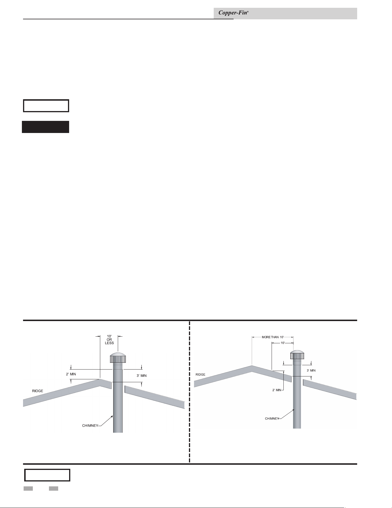
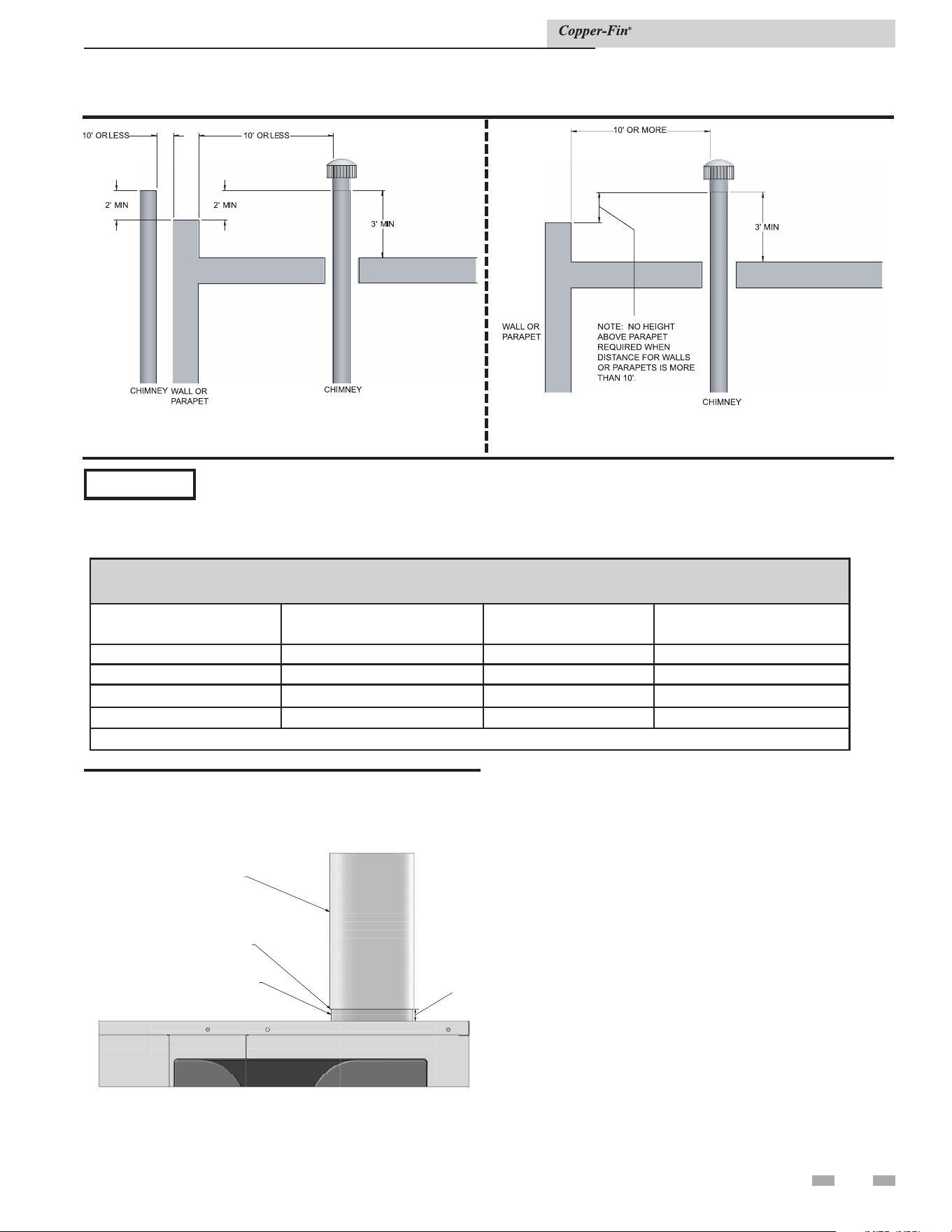
Vertical vent termination clearances and location
The vent terminal should be vertical and exhaust outside the building at least 2 feet (0.61m) above the highest point of the roof
within a 10 foot (3.05m) radius of the termination.
The vertical termination must be a minimum of 3 feet (0.91m) above the point of exit.
A vertical termination less than 10 feet (3.05m) from a parapet wall must be a minimum of 2 feet (0.61m) higher than the parapet
wall.
You must locate the air inlet termination elbow at least 12'' (30cm) above the roof or above normal snow levels.
Keep the vent cap clear of snow, ice, leaves, and debris to avoid blocking the flue.
2 Venting
16
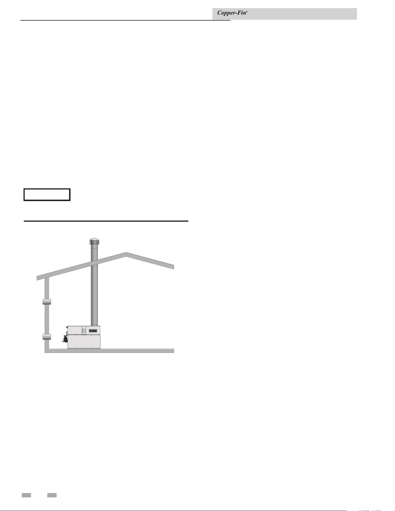
Figure 2-1_Vent termination from peaked roof - 10 ft. or
less from ridge
NOTICE
Vent terminations are not shown in FIG.’s 2-1 thru 2-4. Make sure all vertical vents are installed with vent
terminations recommended by the vent manufacturer.
Figure 2-2_Vent termination from peaked roof - 10 ft. or
more from ridge
⚠ DANGER
Installation & Service Manual
Failure to use correct venting materials can result in loss of life from flue gas spillage into working or living
space.
Vent system must be gas tight sealed to the appliance vent outlet (i.e., silicone) for all venting configurations.
Failure to follow this warning can cause flue products to leak into the cabinet causing damage to the appliance
and can result in gas spillage into the living or work space causing personal injury or death. See FIG. 2-5.
17
2 Venting (continued)
Figure 2-4_Vent termination from flat roof - 10 ft. or more
from parapet wall
Figure 2-3_Vent termination from flat roof - 10 ft. or
less from parapet wall
Vent system options
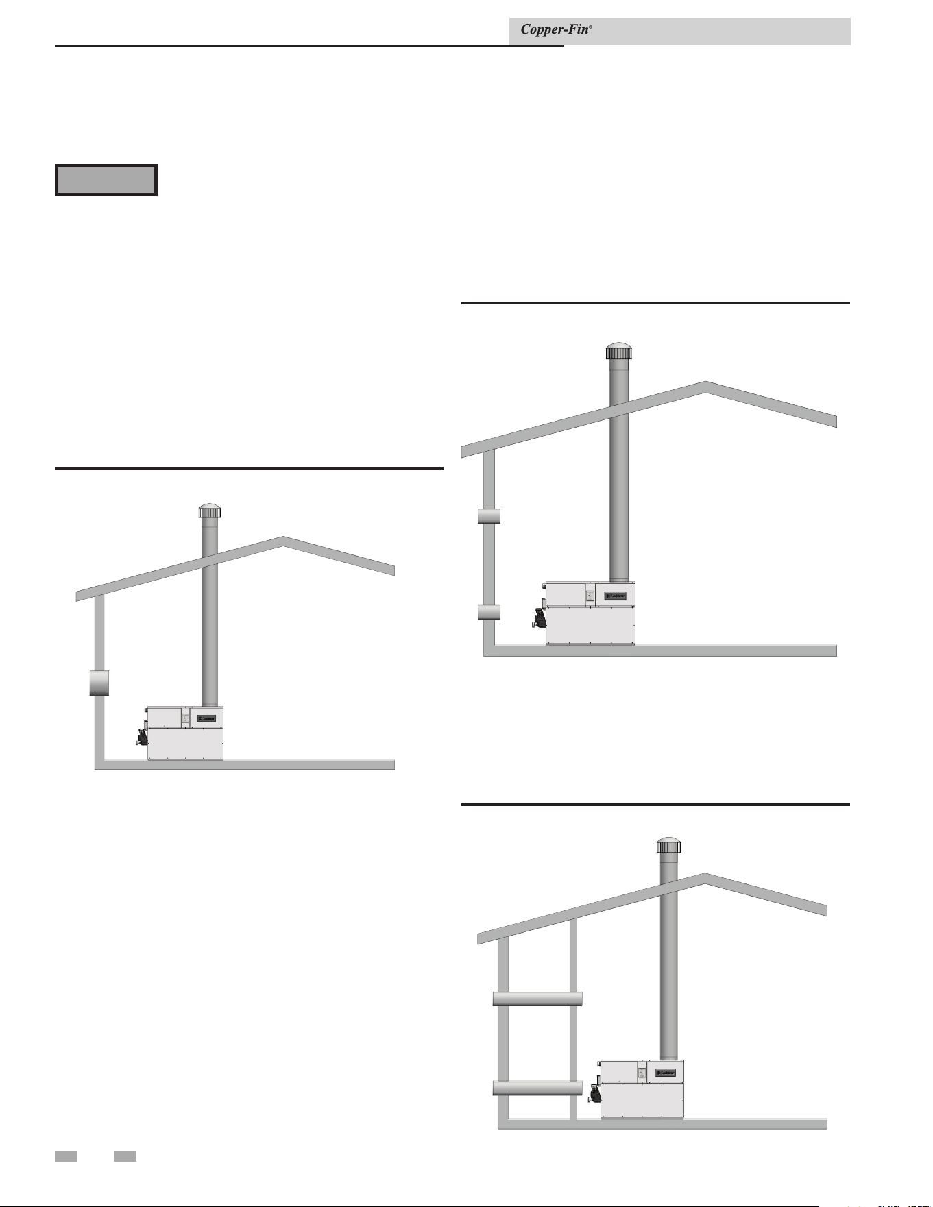
Vent System Options
This fan-assisted Category 1 unit has two venting options.
1. Conventional Negative Draft Venting
This option uses a vertical rooftop flue termination.
Combustion air is supplied from the mechanical room.
See page 15 for detailed information.
2. Outdoor Installation Venting
This option uses the installation of special air inlet and
vent caps on the unit.
All units are shipped from the factory equipped for
conventional negative draft venting. All other optional vent
systems require the installation of specific vent kits and venting
materials. The following is a detailed explanation of the
installation requirements for each venting system, components
used and part numbers of vent kits for each model.
⚠ CAUTION
Units which are shut down or will not operate may experience freezing due to convective air flow in flue
pipe, through the air inlet, or from negative pressure in the equipment room. In cold climates, operate pump
continuously to help prevent freezing of boiler water. Provide proper freeze protection. See Freeze Protection,
page 48.
TABLE 2A
FLUE PIPE SIZES
MODEL FLUE SIZE MODEL FLUE SIZE
497 6'' 1257 12''
647 8'' 1437 12''
747 8'' 1797 14''
987 10'' 2067 14''
Installer may increase diameter one pipe size for ease of installation, if needed.
Installation & Service Manual
Figure 2-5_Vent system must be sealed
1/2"
VENT SYSTEM
UNIT OUTLET
DIR #2000586700 00
SEAL JOINT
(I.E., RTV SILICONE)
2 Venting
18
Barometric damper location
Any venting system option that requires a barometric
damper must adhere to the following directions for optimum
performance. The preferred location for the barometric damper
is in a tee or collar installed in the vertical pipe rising from the
unit’s flue outlet. The barometric damper MUST NOT be
installed in a bull head tee installed on the unit’s flue outlet.
The tee or collar containing the barometric damper should
be approximately three feet vertically above the connection to
the unit’s flue outlet. This location ensures that any positive
velocity pressure from the unit’s internal combustion fan is
dissipated and the flue products are rising due to buoyancy
generated from the temperature of the flue products. Adjust
the weights on the damper to ensure that draft is maintained
within the specified ranges.
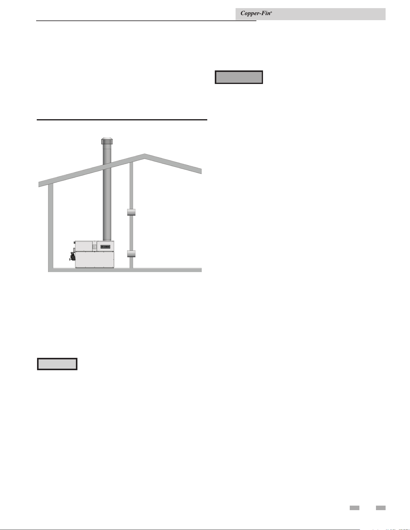
1. Conventional negative draft
venting
NOTICE
Before installing a venting system, follow
all venting clearances and requirements
found in the Venting, General Information
section, page 16.
Figure 2-6_Conventional negative draft vertical venting
with combustion air louvers
On a conventionally vented, negative draft appliance, the
connection from the vent to the chimney or vent termination
on the outside of the building MUST be made with listed Type
"B" double wall (or equivalent) vent connectors and must be
direct as possible with no reduction in diameter. To properly
size all double wall vent connectors and stacks, use the venting
tables in the latest edition of the National Fuel Gas Code, ANSI
Z223.1, in Canada, the latest edition of CGA Standard B149
Installation Code for Gas Burning Appliances and Equipment.
The Type "B" vent and accessories, such as firestop spacers,
thimbles, caps, etc., MUST be installed in accordance with the
manufacturer's listing. The vent connector and firestop must
provide correct spacing to combustible surfaces and seal to the
vent connector on the upper and lower sides of each floor or
ceiling through which the vent connector passes.
Any vent materials used must be listed by a nationally recognized
test agency for use as vent material.
Negative draft
The negative draft in a conventional vent installation must be
within the range of 0.02 to 0.08 inches w.c. to ensure proper
operation. Make all draft readings while the unit is in stable
operation (approximately 2 to 5 minutes).
Connect the flue vent directly to the flue outlet opening on
the top of the unit. No additional draft diverter or barometric
damper is needed on single unit installations with a dedicated
stack and a negative draft within the specified range of 0.02
to 0.08 inches w.c. If the draft in a dedicated stack for a single
unit installation exceeds the maximum specified draft, you
must install a barometric damper to control draft. Multiple unit
installations with combined venting or common venting with
other Category I negative draft appliances require each boiler
to have a barometric damper installed to regulate draft within
the proper range.
Do not connect vent connectors serving appliances vented by
natural draft (negative draft) to any portion of a mechanical
draft system operating under positive pressure. Connecting to a
positive pressure stack may cause flue products to be discharged
into the living space causing serious health injury.
Flue outlet piping
The negative draft in a conventional vent installation must be
within the range of 0.02 to 0.08 inches w.c. to ensure proper
operation. Make all draft readings while the unit is in stable
operation (approximately 2 to 5 minutes).
Connect the flue vent directly to the flue outlet opening on
the top of the unit. No additional draft diverter or barometric
damper is needed on single unit installations with a dedicated
stack and a negative draft within the specified range of 0.02 to
0.08 inches w.c.
You can combine the flue with the vent from any other negative
draft, Category I appliance. Using common venting for multiple
negative draft appliances requires you to install a barometric
damper with each unit. This will regulate draft within the
proper range. You must size the common vent and connectors
from multiple units per the venting tables for Type-B double-
wall vents in the latest edition of the National Fuel Gas Code,
ANSI Z223.1 and/or CAN/CGA-B149 Installation Code.
Common venting systems may be too large when an existing
unit is removed.
Common venting systems
Installation & Service Manual

19
2 Venting (continued)
Common venting systems may be too large when an existing
unit is removed.
At the time of removal of an existing appliance, the following
steps shall be followed with each appliance remaining connected
to the common venting system placed in operation, while other
appliances remaining connected to the common venting system
are not in operation.
1. Seal any unused opening in the common venting system.
2. Visually inspect the venting system for proper size and
horizontal pitch. Make sure there is no blockage or
restriction, leakage, corrosion and other unsafe conditions.
3. If possible, close all building doors and windows. Close all
doors between the space in which the appliances remaining
connected to the common venting system are located and
other building spaces.
4. Turn on clothes dryers and any other appliances not
connected to the common venting system. Turn on any
exhaust fans, such as range hoods and bathroom exhausts,
so they will operate at maximum speed. Do not operate a
summer exhaust fan.
5. Close fire place dampers.
6. Place in operation the unit being inspected. Follow the
lighting instructions. Adjust thermostat so unit will operate
continuously.
7. Test for spillage at the draft hood/relief opening after 5
minutes of main burner operation. Use the flame of a match
or candle, or smoke from a cigarette, cigar or pipe.
8. After making sure that each appliance remaining connected
to the common venting system properly vents when tested
as above, return doors, windows, exhaust fans, fireplace
dampers and other gas burning appliances to their previous
conditions of use.
9. Correct any improper operation of the common venting
system so that the installation conforms to the latest edition
of the National Fuel Gas Code, ANSI Z223.1, in Canada,
the latest edition of CAN/CGA-B149 Installation Code for
Gas Burning Appliances and Equipment. When resizing any
portion of the common venting system, resize to approach
the minimum size as determined using the appropriate
tables of the latest edition of the National Fuel Gas Code,
ANSI Z223.1, in Canada, the latest edition of CAN/
CGA-B149 Installation Code for Gas Burning Appliances
and Equipment.
A masonry chimney must be properly sized for the installation
of a high efficiency gas-fired appliance. Venting of a high
efficiency appliance into a cold or oversized masonry chimney
can result in operational and safety problems. Exterior masonry
chimneys, with one or more sides exposed to cold outdoor
temperatures, are more likely to have venting problems.
The temperature of the flue products from a high efficiency
appliance may not be able to sufficiently heat the masonry
structure of the chimney to generate proper draft. This will
result in condensing of flue products, damage to the masonry
flue/tile, insufficient draft and possible spillage of flue products
into an occupied living space. Carefully inspect all chimney
systems before installation.
Masonry chimney installation
A masonry chimney must be carefully inspected to determine
its suitability for the venting of flue products. A clay-tile-
lined chimney must be structurally sound, straight and free of
misaligned tile, gaps between liner sections, missing sections of
liner or any signs of condensate drainage at the breaching or
clean out. If there is any doubt about the condition of a masonry
chimney, it must be relined with a properly-sized and approved
chimney liner system.
Inspection of a masonry chimney
Follow all vertical venting termination information for
clearances and location under Vertical Vent Termination
Clearances and Location, page 16.
Vertical vent termination clearances and
location
Installation & Service Manual
Venting of high efficiency appliances into a
masonry chimney without a sealed stainless
steel liner can result in operational and safety
problems. Any breaks, leaks, or damage to
the masonry flue/tile will allow spillage of
the positive pressure flue products from the
chimney. These flue products can easily
escape into an occupied living space causing
a health hazard. If there is any doubt about
the condition of a masonry chimney, or
its acceptability for use after insertion of
a corrosion resistant liner system, consult
with local code officials.
CAUTION
2 Venting
Installation & Service Manual
20
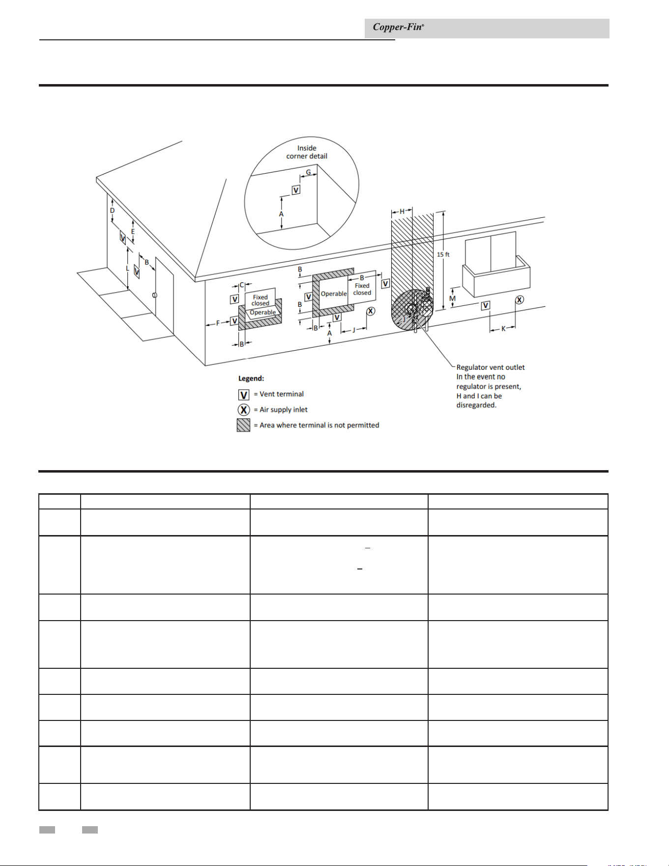
Figure 2-7 Other than Direct Vent Terminal Clearances
Canadian Installations¹ US Installations²
A =
Clearance above grade, veranda, porch,
deck, or balcony
12 in (30 cm) 12 in (30 cm)
B =
Clearance to window or door that may
be opened
6 in (15 cm) for appliances < 10,000 Btuh
(3 kW), 12 in (30 cm) for appliances >
10,000 Btuh (3 kW) and < 100,000 Btuh
(30 kW), 36 in (91 cm) for appliances >
100,000 Btuh (30 kW)
4 ft (1.2 m) below or to side of opening; 1 ft
(300 mm) above opening
C =
Clearance to permanently closed
window
* *
D =
Vertical clearance to ventilated soffit
located above the terminal within a
horizontal distance of 2 ft (61 cm) from
the center line of the terminal.
* *
E = Clearance to unventilated soffit
* *
F = Clearance to outside corner
* *
G = Clearance to inside corner
* *
H =
Clearance to each side of center line
extended above meter / regulator
assembly
3 ft (91 cm) within a height 15 ft (4.6 m)
*
I =
Clearance to service regulator vent
outlet
3 ft (91 cm)
*
Table 2B Other than Direct Vent Terminal Clearances
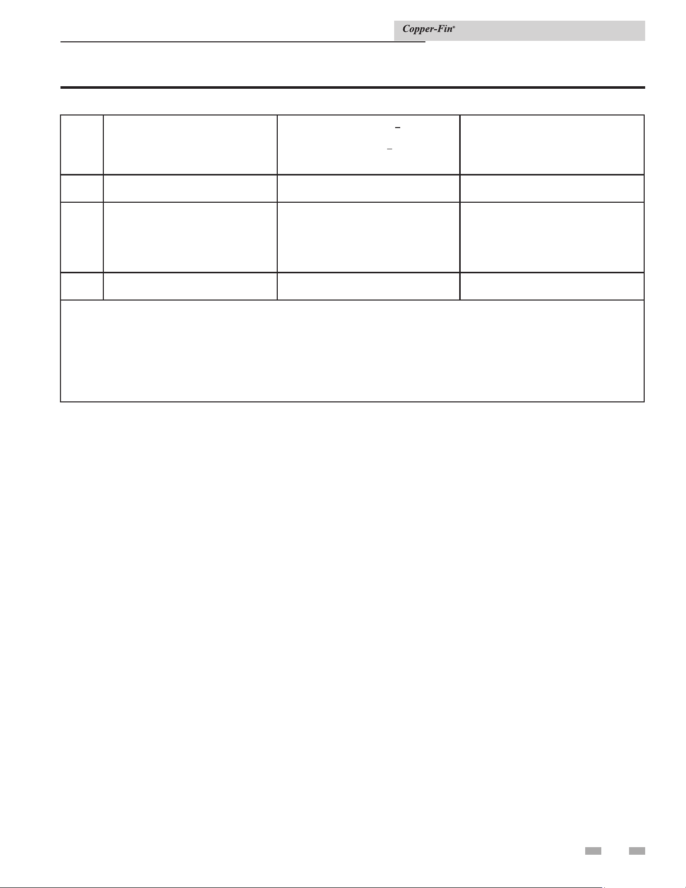
2 Venting (continued)
Installation & Service Manual
21
J =
Clearance to nonmechanical air supply
inlet to building or the combustion air
inlet to any other appliance
6 in (15 cm) for appliances < 10,000 Btuh
(3kW), 12 in (30 cm) for appliances >
10,000 Btuh (3 kW) and < 100,000 Btuh
(30 kW), 36 in (91 cm) for appliances >
100,000 Btuh (30 kW)
4 ft (1.2 m) below or to side of opening; 1 ft
(300 mm) above opening
K =
Clearance to a mechanical air supply
inlet
6 ft (1.83 m) 3 ft (91 cm) above if within 10 ft (3 m)
horizontally
L =
Clearance above paved sidewalk or
paved driveway located on public
property
7 ft (2.13 m)† 7 ft (2.13 m) for mechanical draft systems
(Category I appliances). Vents for
Category II and IV appliances cannot be
located above public walkways or other
areas where condensate or vapor can
cause a nuisance or hazard
M =
Clearance under veranda, porch, deck,
or balcony
12 in (30 cm)‡ *
* Clearance in accordance with local installation codes and the requirements of the gas supplier.
† A vent shall not terminate directly above a sidewalk or paved driveway that is located between two single family dwellings
and serves both dwellings.
‡ Permitted only if veranda, porch, deck, or balcony is fully open on a minimum of two sides beneath he oor.
NOTES:
1) In accordance with the current CSA B149.1, Natural Gas and Propane Installation Code
2) In accordance with the current ANSI Z223.1/NFPA 54, National Fuel Gas Code
Table 2B Other than Direct Vent Terminal Clearances (continued)
2 Venting
22
2. Outdoor installation venting
Units are self-venting and can be used outdoors when installed
with the optional outdoor systems. The air inlet cap mounts
directly to the unit and covers the combustion air opening.
Gasketing is supplied to seal the unit vent pipe to prevent water
leakage. The flue requires a 36" vent pipe and cap installed to
the heater outlet.
Combustion air supply must be free of contaminants (see
Combustion and Ventilation Air, page 12). To prevent
recirculation of the flue products into the combustion air inlet,
follow all instructions in this section.
NOTICE
Before installing a venting system, follow
all venting clearances and requirements
found in the Venting, General Information
section, page 16.
⚠ WARNING
Only install outdoor models outdoors
and only use the vent systems supplied
by the appliance manufacturer. Personal
injury or product damage may result if
any other cap is used or if an outdoor
model is used indoors. Properly install all
covers, doors and jacket panels to ensure
proper operation and prevent a hazardous
condition.
Keep venting areas free of obstructions. Keep area clean and
free of combustible and flammable materials. Maintain a
minimum clearance of 3'' (76mm) to combustible surfaces and
36" clearance to the rear of the unit for outdoor installations.
To avoid a blocked air inlet or blocked flue condition, keep the
air inlet, flue outlet, and drain slot clear of snow, ice, leaves,
debris, etc.
Outdoor vent/air inlet location
Do not install outdoor models directly on
the ground. You must install the outdoor
unit on a concrete, brick, block, or other
non-combustible pad.
Do not locate unit so that high winds
can deflect off of adjacent walls, buildings
or shrubbery causing recirculation.
Recirculation of flue products may cause
operational problems, bad combustion or
damage to controls. Locate unit at least
3 feet (0.91m) from any wall or vertical
surface to prevent wind conditions from
affecting performance.
Multiple outdoor unit installations require
48'' (1.22m) clearance between each vent
cap. Locate the outdoor cap at least 48''
(1.22m) below and 48'' (1.22m) horizontally
from any window, door, walkway or gravity
air intake.
Locate the unit at least 10 feet (3.05m) away
from any forced air inlet.
Locate the unit at least 3 feet (0.91m) outside
any overhang.
CAUTION
CAUTION
Clearances around outdoor installations can
change with time. Do not allow the growth
of trees, shrubs or other plants to obstruct
the proper operation of the outdoor vent
system.
CAUTION
Installation & Service Manual
NOTICE
Do not install in locations where rain from
building runo drains will spill onto the
unit.
CAUTION
A minimum of 3 feet must be maintained
at all times from outdoor air vent cap
surfaces to combustible construction and/or
materials.
Do not install in pit or below grade.
CAUTION

23
2 Venting (continued)
e optional outdoor vent kit is available from the appliance manufacturer. e outdoor kit part numbers are listed by unit size. See
Table 2C for kit numbers. Complete installation instructions are included with the outdoor vent kit. is kit requires a 36" vent pipe
and cap (eld supplied).
For installation examples see FIG.’s 2-8 and 2-9.
Outdoor vent kit
DIR #2000597290 00
3'
3'
3'
3'
Figure 2-8_Outdoor vent kit installed on Models
497 - 747
Figure 2-9_Outdoor vent kit installed on Models
987 - 2067
DIR #2000597290 00
3'
3'
3'
3'
3'
TABLE 2C
Outdoor Vent Stack Kits
Model
Kit*
without Pump Cover
Kit*
with Pump Cover
497 100337237 100337591
647 100337239 100337592
747 100337239 100337592
987 100337365 100337593
1257 100337366 100337594
1437 100337366 100337594
1797 100337370 100337596
2067 100337370 100337596
* ese kits include an outdoor air cap and ue gasket.
** 36" minimum vent pipe and cap supplied by installer.
Installation & Service Manual
3 Gas connections
24
Connecting to gas supply
Verify that the appliance is supplied with the type of gas specified
on the rating plate. This appliance is configured for operation
up to 2000 feet altitude. Consult factory for installations above
2000 feet elevation.
Inlet gas pressure: Measured at the inlet pressure tap on the
appliance gas manifold. The pressure tap is located upstream of
the combination gas valve(s).
See Table 3A for maximum and minimum inlet pressures. Do
not exceed the maximum. Minimum inlet pressure is for the
purpose of input adjustment.
TABLE 3A
INLET GAS PRESSURE
MODEL
NATURAL LP
Max.
w.c.
Min.
w.c.
Max.
w.c.
Min.
w.c.
497 - 2067 14'' 4.5'' 14.0'' 8.0''
Manifold pressure: The gas regulator on the unit’s
combination gas valve is adjustable to supply proper manifold
pressure for normal operation.
Gas pressure test
1. The appliance must be disconnected from the gas
supply piping system during any pressure testing of that
system at a test pressure in excess of 1/2 PSIG (3.5 kPa).
2. The appliance must be isolated from the gas supply
piping system by closing a manual shutoff valve during
any pressure testing of the gas supply piping system at
test pressures equal to or less than 1/2 PSIG (3.5 kPa).
3. The appliance and its gas connection must be leak
tested before placing it in operation.
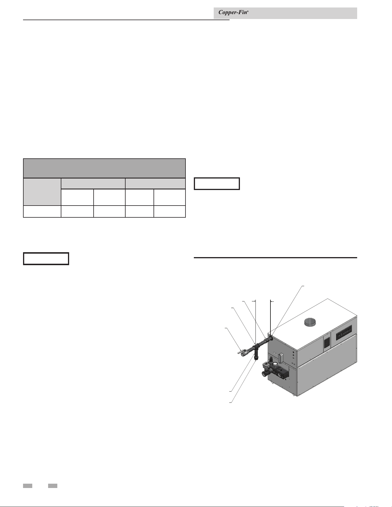
Gas piping
To safely operate this unit, you must properly size the gas
supply piping. See Tables 3B through 3D for piping and
fitting requirements. Gas pipe size may be larger than heater
connection.
The gas connection for Models 497 - 747 is 1 1/4'' NPT and on
Models 987 - 2067 the gas connection to these units is 2'' NPT.
For ease of service, install a union.
Figure 3-1_Gas line connection
C
C
A
A
P
P
N
N
I
I
P
P
P
P
L
L
E
E
M
M
A
A
NU
NU
A
A
L
L
M
M
A
A
I
I
N
N
S
S
H
H
U
U
T
T
O
O
F
F
F
F
VA
VA
L
L
V
V
E
E
UN
UN
I
I
O
O
N
N
C
C
O
O
U
U
P
P
L
L
I
I
N
N
G
G
8"
8"
M
M
I
I
N
N
U
U
S
S
E
E
W
W
R
R
E
E
NC
NC
H
H
T
T
O
O
H
H
O
O
L
L
D
D
S
S
U
U
P
P
P
P
L
L
Y
Y
P
P
I
I
P
P
E
E
NOTICE
It is the installer’s responsibility to supply
the sediment trap (drip leg).
The combination gas valves have an integral vent limiting
device and do not require venting to atmosphere, outside the
building. The unit will not operate properly if the reference hose
is removed or a vent to atmosphere is installed.
Optional gas controls may require routing of bleeds and vents
to the atmosphere, outside the building when required by local
codes.
Install a manual main gas shutoff valve, outside of the unit gas
connection within six feet of the unit in accordance with the
requirements of the National Fuel Gas Code, ANSI Z223.1.
You must provide a sediment trap (drip leg) in the inlet of the
gas connection to the unit.
Installation & Service Manual
NOTICE
If an inline high gas pressure regulator is
used, it MUST BE of the lockup type and
be located a minimum of 10 feet from the
appliance. Failure to do so may result in
insufficient gas volume supplied to the
appliance.
If you must adjust regulator pressure, follow the instructions
under Gas Manifold Pressure Adjustment on page 27. Do not
increase regulator pressure beyond specified pressure setting.
25
3 Gas connections (continued)
Gas connection
All gas connections must be made with pipe joint compound
resistant to the action of liquefied petroleum (L.P.) and natural
gases. All piping must comply with local codes and ordinances.
Piping installations must comply with approved standards and
practices.
1. Make sure gas line is a separate line direct from the meter
unless the existing gas line is of sufficient capacity. Verify
pipe size with your gas supplier.
2. Use new, properly threaded black iron pipe free from
chips. If you use tubing, make sure the ends are cut
square, deburred and clean. Make all tubing bends smooth
and without deformation. Avoid flexible gas connections.
Internal diameter of flexible lines may not provide unit with
proper volume of gas.
3. Install a manual main gas shutoff valve at the unit’s gas inlet,
outside of the unit.
4. Run pipe or tubing to the unit’s gas inlet. If you use tubing,
obtain a tube to pipe coupling to connect the tubing to the
unit’s gas inlet.
5. Install a sediment trap in the supply line to the unit’s gas
inlet (see FIG. 3-1).
6. Apply a moderate amount of good quality pipe compound
(do not use Teflon tape) to pipe only, leaving two end
threads bare.
7. Remove seal over gas inlet to unit.
8. Connect gas pipe to inlet of unit. Use wrench to support gas
manifold on the unit.
9. For L.P. gas, consult your L.P. gas supplier for expert
installation.
10. Ensure that all air is completely bled from the gas line before
starting the ignition sequence. Start up without properly
bleeding air from the gas line may require multiple reset
functions of the ignition control module to achieve proper
ignition.
⚠ WARNING
Do not have any open flame in proximity to
the gas line when bleeding air from the gas
line. Gas may be present.
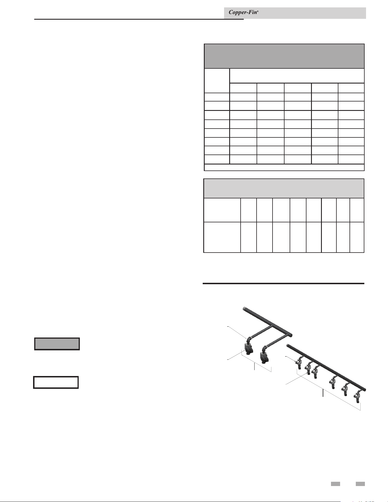
TABLE 3C
FITTINGS TO EQUIVALENT STRAIGHT PIPE
Diameter
Pipe
(inches)
3/4 1 1 1/4 1 1/2 2 3 4 5
Equivalent
length of
Straight Pipe
(feet)
2 2 3 4 5 10 14 20
TABLE 3B
SUGGESTED GAS PIPE SIZE FOR
SINGLE UNIT INSTALLATIONS
MODEL
Distance from Meter (in feet)
0 - 50 51 - 100 101 - 200 201 - 300 301 - 500
497 1 1/4'' 1 1/4'' 1 1/2'' 2'' 2''
647 1 1/4'' 1 1/2'' 2'' 2'' 2 1/2''
747 1 1/2'' 2'' 2'' 2 1/2'' 2 1/2''
987 2'' 2'' 2 1/2'' 2 1/2'' 3''
1257 2'' 2 1/2'' 2 1/2'' 3'' 3''
1437 2 1/2'' 2 1/2'' 3'' 3'' 3 1/2''
1797 2 1/2'' 3'' 3'' 3 1/2'' 3 1/2''
2067 2 1/2'' 3'' 3'' 3 1/2'' 4''
For each elbow or tee, add equivalent straight pipe to total length from Table 3C.
Gas train and controls
NOTICE
The gas train and controls assembly
provided on this unit have been tested under
the applicable American National Standard
to meet minimum safety and performance
criteria such as safe lighting, combustion
and safety shutdown operation.
COMBINATION
VALVE
TO BURNERS
497 MODEL
COMBINATION
VALVE
DOWNSTREAM
TEST VALVE
TO BURNERS
DO
WNSTREAM
TEST VALV
E
2067 MODEL
Figure 3-2_Gas train drawing
Water heater models do not have downstream test valves, but
the rest of the gas train is represented by FIG. 3-2.
Installation & Service Manual
3 Gas connections
26
Combination gas valves
These units fire in multiple stages of burner input. Each stage
of burner operation has a combination gas valve(s) to cycle
the gas supply on and off and regulate gas to the burners. Each
combination valve consists of a gas regulator and two valve seats
to meet the requirements for redundant gas valves. The valve
has a gas control knob that must remain in the open position
at all times when the unit is in service. The gas control valve
has pressure taps located on the inlet and discharge sides of the
valve. Manifold pressure is adjusted using the regulator located
on the valve. A manifold gas pressure tap for each burner
stick is located on the discharge side of the valve. The manifold
pressure is preset at the factory and adjustment is not usually
required. If you must adjust regulator pressure, follow the
instructions under Gas Manifold Pressure Adjustment, page 27.
Venting of combination gas valves
The combination gas valve/regulator used on all units is
equipped with an integral vent limiting orifice per ANSI Z21.78.
The vent limiter ensures that the volume of gas emitted from
the valve in the event of a failed gas diaphragm does not exceed
the maximum safe leakage rate allowed by agency requirements.
Combination gas valve/regulators equipped with integral vent
limiters are not required to have vent or relief lines piped to
the outdoors. The termination of the vent limited opening on
the combination gas valve/regulator complies with the safety
code requirements of CSD-1, CF-190(a) as shipped from the
appliance manufacturer without the installation of additional
vent lines.
Checking gas supply pressure
Use the following procedure to check gas supply pressure.
1. Turn the main power switch to the “OFF” position.
2. Turn gas valve knobs to the “OFF” position.
3. Shut off gas supply at the field-installed manual gas cock in
the gas piping to the unit. If fuel supply is L.P. gas, shut off
gas supply at the tank.
4. Remove the 1/8'' hex plug, located on the “inlet” side of the
gas valve (FIG. 3-3). You may also use a tapping on the
field-installed main manual gas cock or gas piping. Install a
fitting in the inlet pressure tapping suitable to connect to a
manometer or magnehelic gauge. Range of scale should be
14'' w.c. or greater to check inlet pressure.
5. Turn on gas supply at the manual gas cock, turn on L.P. gas
at the tank if required.
6. Turn the power switch to the “ON” position.
7. Turn the gas valve knobs to the “ON” position. Set the
electronic temperature control or thermostat to call for
heat.
8. Observe the gas supply pressure as all burners are firing.
Ensure that inlet pressure is within the specified range.
See Connecting To Gas Supply, page 24 for minimum and
maximum gas supply pressures.
9. If gas pressure is out of range, contact gas utility, gas
supplier, qualified installer or service agency to determine
necessary steps to provide proper gas pressure to the
control.
Installation & Service Manual
TABLE - 3D
Capacity of Schedule 40 Metallic Pipe in Cubic Feet of Natural Gas Per Hour
(based on .60 specific gravity, 0.30" w.c. pressure drop)
Pipe
Size
(Inches)
Length of Pipe in Straight Feet
10 20 30 40 50 60 70 80 90 100 125 150 175 200
1/2 131 90 72 62 55 N/A N/A N/A N/A N/A N/A N/A N/A N/A
3/4 273 188 151 129 114 104 95 89 83 79 70 63 58 N/A
1 514 353 284 243 215 195 179 167 157 148 131 119 109 102
1 1/4 1,060 726 583 499 442 400 368 343 322 304 269 244 224 209
1 1/2 1,580 1,090 873 747 662 600 552 514 482 455 403 366 336 313
2 3,050 2,090 1,680 1,440 1,280 1,160 1,060 989 928 877 777 704 648 602
2 1/2 4,860 3,340 2,680 2,290 2,030 1,840 1,690 1,580 1,480 1,400 1,240 1,120 1,030 960
3 8,580 5,900 4,740 4,050 3,590 3,260 3,000 2,790 2,610 2,470 2,190 1,980 1,820 1,700
4 17,500 12,000 9,660 8,270 7,330 6,640 6,110 5,680 5,330 5,040 4,460 4,050 3,720 3,460
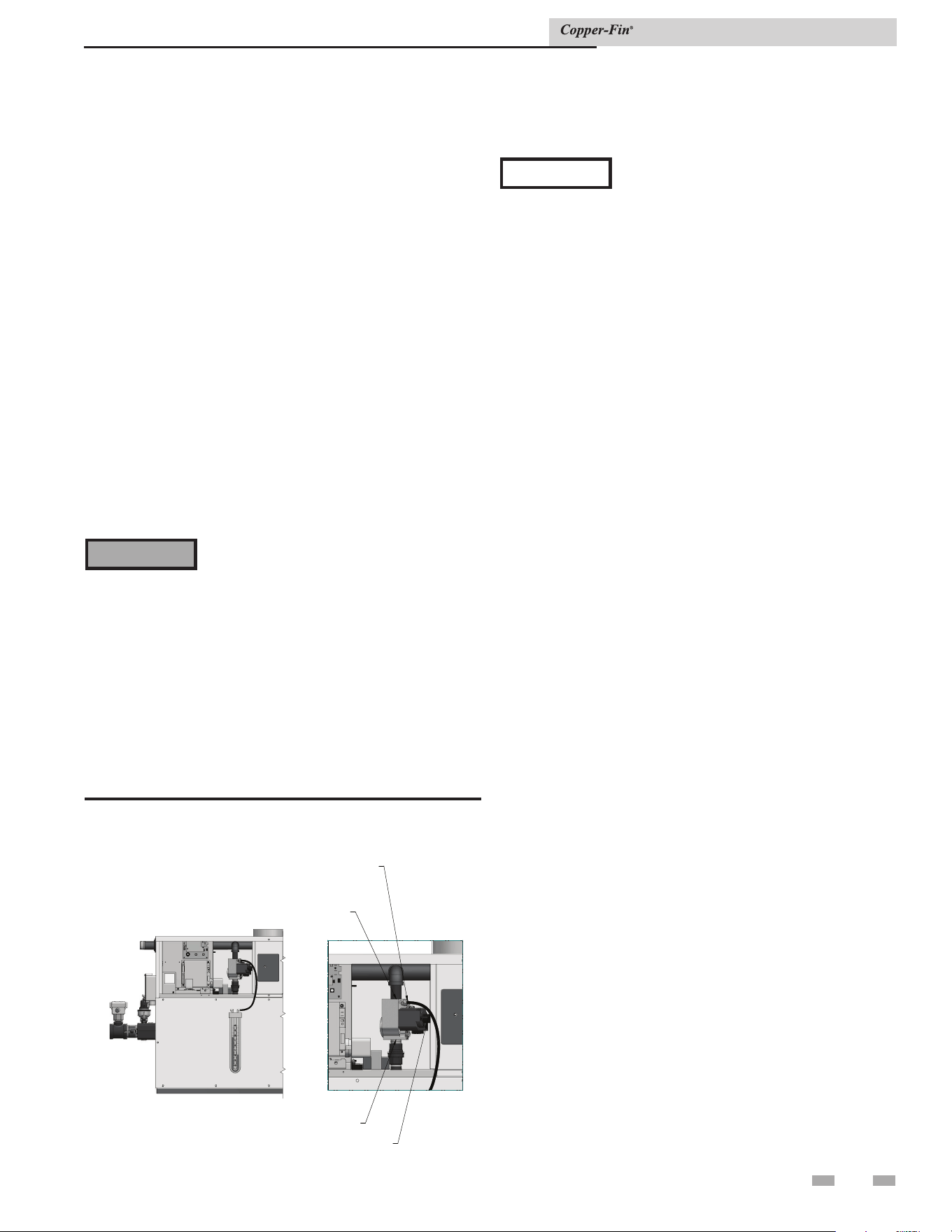
NOTICE
The gas valves are referenced to the fan
pressurized chamber by a hose connected
from the vent of the gas valve regulator
to the chamber pressure tap located on
the front inside portion of the jacket.
Reference the drawings in this section for
component and connection points for
pressure measurement. The referenced
chamber pressure must be subtracted from
the manifold pressure to obtain actual net
manifold pressure for normal operation.
A manometer or magnahelic gauge legible
in 0.1'' increments up to 10 inches w.c. is
required to check and adjust the manifold
pressure. The regulator cover screw on the
gas valve must be in place and tight for the
unit to operate properly.
27
3 Gas connections (continued)
10. If gas supply pressure is within normal range, remove the
gas manometer and replace the pressure tap fittings in the
gas control as indicated by the following steps.
11. Turn power switch to the “OFF” position.
12. Turn gas valve knob to the “OFF” position.
13. Shut off gas supply at the manual gas cock in the gas piping
to the unit. If fuel supply is L.P. gas, shut off gas supply at
the tank.
14. Remove the manometer and related fittings from the “inlet
side of the gas valve, replace 1/8'' hex plug in the gas valve
and tighten.
15. Turn on the gas supply at the manual valve, turn on L.P. gas
at the tank if required.
16. Turn the power switch to the “ON” position.
17. Turn the gas valve knob to the “ON” position.
18. Set the electronic temperature control or thermostat to call
for heat.
⚠ WARNING
After completing any testing on the gas
system, leak test all gas connections. Apply
a soap/water solution to all gas connections
while main burners are operating. Bubbles
forming indicate a leak. Repair all leaks at
once. Do not operate this unit with a leak in
the gas train, valves or related piping.
Check burner performance by cycling the system while you
observe burner response. Burners should ignite promptly.
Flame pattern should be stable, see Burner Flames in the
Maintenance section of this manual. Turn system off and allow
burners to cool, then cycle burners again to ensure proper
ignition and flame characteristics.
INLET
G
G
A
A
S
S
V
V
A
A
L
L
V
V
E
E
C
C
O
O
N
N
T
T
R
R
O
O
L
L
K
K
N
N
O
O
B
B
O
O
U
U
T
T
L
L
E
E
T
T
SUPPLY INLET
PRESSURE TAP
Figure 3-3_Measuring gas supply pressure at combination
gas valve
Gas manifold pressure adjustment
1. Remove the thumbscrew that fastens the control panel
access door and remove the door.
2. Turn the power switch located in the lower left corner
behind the control panel access door to the “O” or “OFF”
position.
3. Remove the top front jacket access panels to access the gas
valve(s).
4. Locate the reference hose on the first gas valve which goes
from the vent fitting on the gas valve to the barbed fitting
on the deck of the unit (see FIG. 3-4).
5. Remove the flexible cap from the barbed fitting on the “tee”
located in this line and hook one side of the manometer, or
(-) side of a magnahelic gauge, to this “tee”. Retain this cap
for future use.
6. Remove the 1/8'' hex plug from the manifold pressure tap
on the gas valve (see FIG. 3-4). Retain plug for future use.
7. Install a fitting in this tap that is suitable for connection of
a hose to a manometer, or (+) side of a magnahelic gauge
(see FIG. 3-4).
8. Turn the power switch to the “I” or “ON” position.
9. Push the reset button(s) for the ignition control(s), if
necessary.
10. Set the temperature control to call for heat (see Setting
Temperature Control, page 41).
11. Once the unit is firing, the manometer/magnahelic will
reflect the net manifold gas pressure. Compare this reading
to the respective value in Table 3E for Natural Gas or
Propane Gas.
Installation & Service Manual
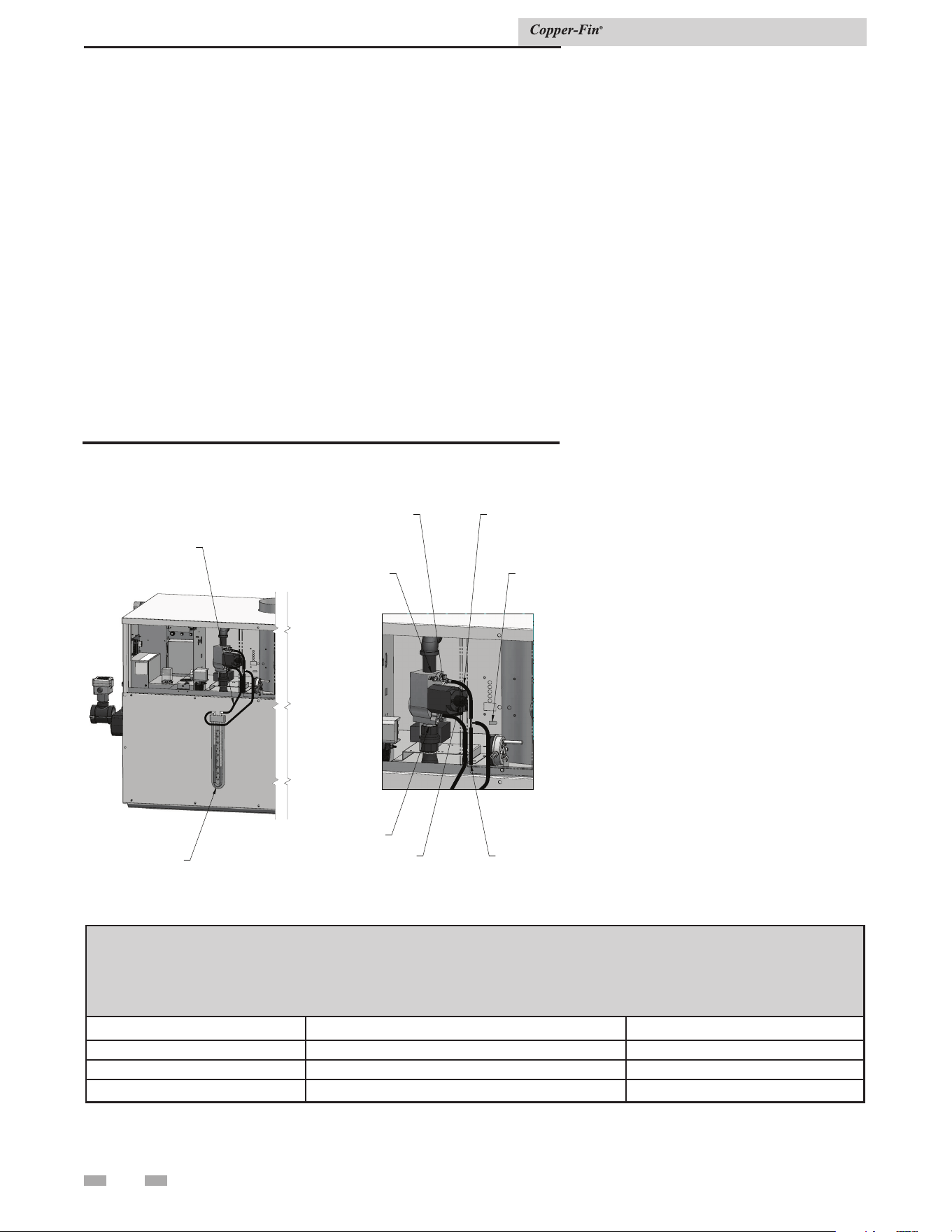
3 Gas connections
28
12. If adjustment is necessary, remove the regulator
cover screw on the gas valve. Note: If the gas valve
under adjustment is located on a manifold assembly
monitored by an igniter, the unit may shut down and
recycle when the regulator cover screw is removed.
This is normal.
13. Turn the regulator adjustment screw “clockwise” to
raise the regulator gas pressure. Turn the regulator
adjustment screw “counterclockwise” to lower the
regulator gas pressure.
14. Replace the regulator cover screw and make sure it is
tight for proper operation.
PRESSURE
REGULATOR
ADJUSTMENT
(UNDER CAP
SCREW)
INLET
OUTLET
GAS
VALVE
CONTROL
KNOB
MANOMETER
MANIFOLD
PRESSURE
CHAMBER
PRESSURE
TEE
TO BARBED
FITTING
Figure 3-4_Measuring manifold gas pressure
TABLE 3E
Net Manifold Pressure
Regulator Pressure Less
Front Chamber Pressure
MODEL Nat. Gas LP
497 - 747 1.8'' w.c. --
987 - 2067 1.2'' w.c. --
497-2067 -- 4.6'' w.c.
Installation & Service Manual
15. Read the value on the manometer/magnahelic and
compare it to the values in TABLE- 3E.
16. Repeat this adjustment procedure for each gas valve as
necessary to adjust to the proper manifold gas pressure.
17. Remove hoses, replace and tighten plugs and caps
when complete.
18. Replace top front upper jacket access panels and
control panel door in reverse order.
19. If proper ignition and burner operation is not
achieved after checking gas supply pressure, see
Cleaning and Maintenance, page 61 for Combustion
Air Fan Adjustment. Follow the procedure to adjust
the combustion air fans as necessary.
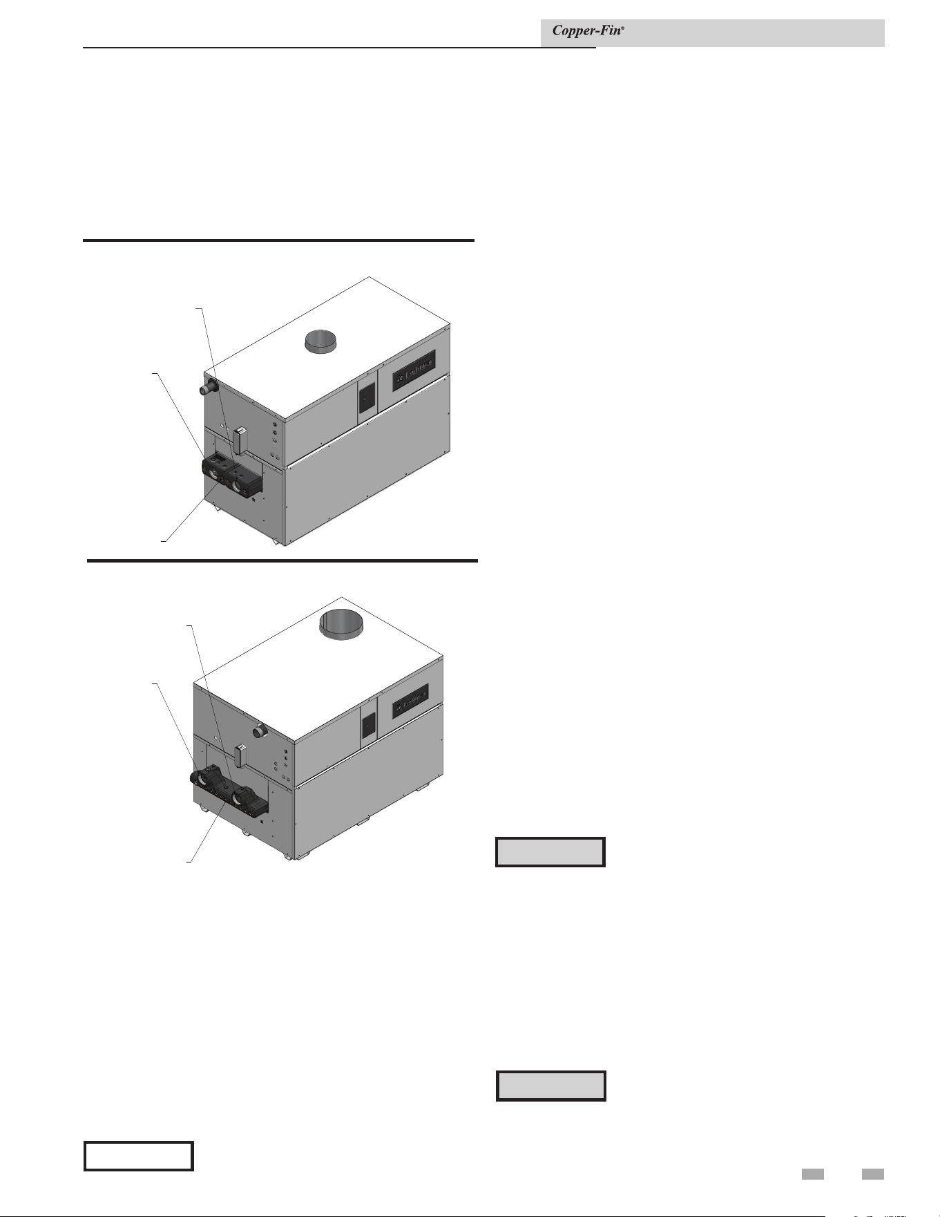
29
4 Water connections
Inlet and outlet connections
For ease of service, install unions on the water inlet and water
outlet of the unit. The connection to the unit marked “Inlet”
on the header should be used for return from the system. The
connection on the header marked “Outlet” is to be connected to
the supply side of the system.
NEED NEW IMAGE
Figure 4-1_Water Connections_Models 497 - 797
2" NPT
WATER
INLET
INSPECTION
PLUGS
2" NPT
WATER
OUTLET
Relief valve
This unit is supplied with a relief valve(s) sized in accordance
with ASME Boiler and Pressure Vessel Code, Section IV
(“Heating Boilers”). The relief valve(s) is installed in the vertical
position and mounted in the hot water outlet. No valve is to be
placed between the relief valve and the unit. To prevent water
damage, the discharge from the relief valve shall be piped to a
suitable floor drain for disposal when relief occurs. No reducing
couplings or other restrictions shall be installed in the discharge
line. The discharge line shall allow complete drainage of the
valve and line. Relief valves should be manually operated at
least once a year.
⚠ CAUTION
Avoid contact with hot discharge water.
Water flow switch
A water flow switch is factory installed in the outlet piping on
all heating boilers and water heaters. The flow switch must
prove water flow before a trial for ignition can begin. The flow
switch requires a minimum flow of 15 - 18 GPM on Models
497 - 747 and 26 GPM on Models 987 - 2067 to make the flow
switch and start burner operation. A water flow switch meets
most code requirements for a low water cutoff device on boilers
requiring forced circulation for operation.
Low water cutoff (if equipped)
If this boiler is installed above radiation level, a low water
cutoff device must be installed at the time of boiler installation.
An electronic low water cutoff is available as a factory supplied
option on all models. The low water cutoff should be inspected
every 6 months.
Heating boiler installations
Piping of the boiler system
The drawings in this section show typical boiler piping
installations, see FIG.’s 4-5 through 4-8. Before beginning
the installation, consult local codes for specific plumbing
requirements. The installation should provide unions and
valves at the inlet and outlet of the boiler so it can be isolated
for service. An air separation device must be supplied in the
installation piping to eliminate trapped air in the system.
Locate a system air vent at the highest point in the system.
The system must also have a properly sized expansion tank
installed. Typically, an air charged diaphragm-type expansion
tank is used. The expansion tank must be installed close to the
boiler and on the suction side of the system pump to ensure
proper operation. A water meter to monitor makeup water is
recommended. Makeup water volume should not exceed 5%
of total system per yearInstall a Y-strainer or equivalent multi-
purpose strainer just before the boiler pump at the inlet of the
heat exchanger. This item is used to remove system debris from
older hydronic systems and to protect newer systems.
⚠ CAUTION
The boiler system should not be operated
at less than 12 PSIG(83 kPa) (Non-metallic
system piping must have an oxygen barrier
to be considered a closed loop).
Hot water piping must be supported by suitable hangers or floor
stands, NOT by the boiler. Copper pipe systems will be subject
to considerable expansion and contraction. Rigid pipe hangers
could allow the pipe to slide in the hanger resulting in noise
transmitted into the system. Padding is recommended on rigid
hangers installed with a copper system. The boiler pressure
relief valve must be piped to a suitable floor drain. See the Relief
Valve section on this page.
⚠ CAUTION
A leak in a boiler “system” will cause the
“system” to intake fresh water constantly,
which will cause the tubes to accumulate a
lime/scale build up. This will cause a non-
warrantable failure.
Installation & Service Manual
Figure 4-2_Water Connections_Models 987 - 2067
2-1/2" NPT
WATER
INLET
INSPECTION
PLUGS
2-1/2" NPT
WATER
OUTLET
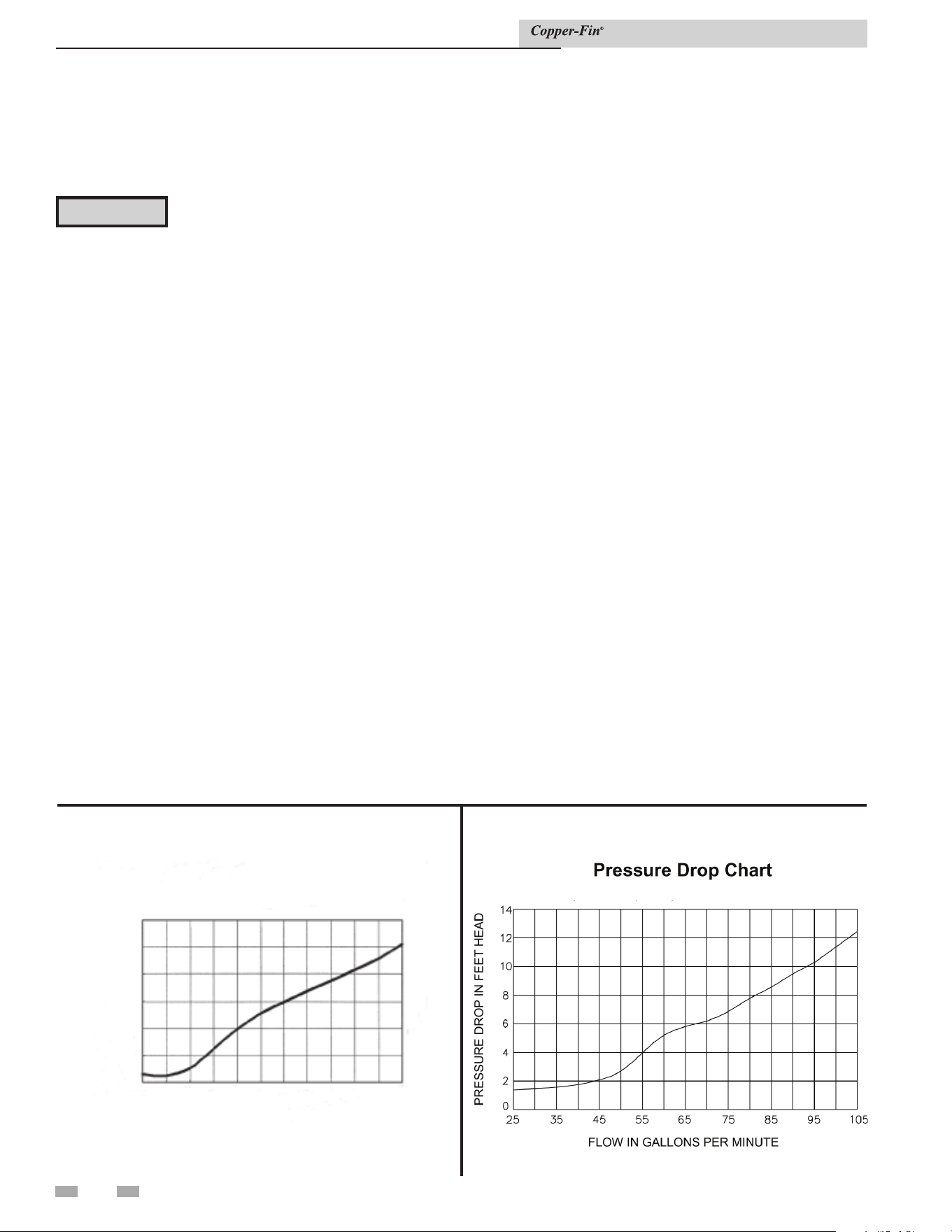
4 Water connections
30
Boiler circulator requirements
This is a low mass, high efficiency hot water boiler which
must have adequate flow for quiet, efficient operation. Pump
selection is critical to achieve proper operation. A pump should
be selected to achieve proper system design water temperature
rise. Pipe diameter and length are critical to ensure proper flow
through the boiler. A System Temperature Rise Chart (Table 4B
Circulator pump specifications
1. Maximum operating pressure for the pump must exceed
system operating pressure.
2. Maximum water temperature should not exceed the
nameplate rating.
3. Cast iron circulators may be used for closed loop systems.
4. A properly sized expansion tank must be installed near the
boiler and on the suction side of the pump.
FLOW IN GALLONS PER MINUTE
PRESSURE DROP IN FEET HEAD
Pressure Drop Chart
Models 497 - 747
80
75
70
65
60
55
50
45
40
30
20
10
0
2
4
6
8
10
12
MODELS 987 - 2067
Figure 4-4_Heat exchanger pressure drop chart_
Models 987 - 2067
Figure 4-3_Heat exchanger pressure drop chart_
Models 497- 747
Installation & Service Manual
Circulator pump operation (heating boilers only)
The boiler pump must run when the boiler is firing. Separate
supply circuits can be provided or the two circuits (pump
and controls) can be combined for connection to one circuit,
properly sized for both.
Pump delay operation
A pump delay operation feature is provided. The boiler’s
circulating pump will cycle on at each call for heat, before the
burner fires. The pump will continue to operate while the
burner is firing. The pump will run for a minimum 30 second
period after the temperature set point is satisfied. This timing
will remove any of the residual heat from the combustion
chamber before turning the pump off. See the wiring diagram
in Section 10 of this manual.
Water connections (heating boilers only)
Inlet and outlet water connections on Models 497 - 747
have 2'' NPT and on Models 987 - 2067 the inlet and outlet
connections are 2 1/2'' NPT.
⚠ CAUTION
Field installed reducing bushings must not
be used to reduce below the pipe diameters
of the models listed above.
Any reduction in pipe size may decrease flow resulting in high
water temperatures, boiler noise, flashing to steam, and non-
warrantable heat exchanger damage.
The boiler may be installed with a primary/secondary piping
system provided to the boiler. It is important to guarantee that
adequate flow is provided to properly dissipate heat from the
boiler and also ensure that flow through the boiler does not
exceed the maximum recommended flow rate of 55 GPM for
Models 497 - 747 and 90 GPM for Models 987 - 2067 for a boiler
equipped with a copper heat exchanger.
on page 32) is provided to assist in proper pump selection. This
table provides GPM and boiler head-loss at various temperature
rises for each model based on Btu/hr input. Temperature rise
is the difference in boiler inlet temperature and boiler outlet
temperature while the boiler is firing at full rate.
Example: The boiler inlet temperature is 160°F (71.1°C) and
the boiler outlet temperature is 180°F (82.2°C). This means that
there is a 20°F (11.1°C) temperature rise across the boiler. The
boiler temperature rise is visible in the Operator Interface on the
boiler’s front control panel.

31
4 Water connections (continued)
A buffer tank is an effective way to enhance a small system load
and increase heating system efficiency (see FIG. 4-8 on page 36
of this manual). Buffer tanks add water volume to the system
and act as a flywheel to absorb the additional Btu’s provided by
the boiler when only a single zone of a large system is calling
for heat.
To calculate the proper buffer tank size for a multiple zone
system:
(Run Cycle) (Output - Minimum System Load)
(Temp. Rise) (8.33) (60 Min.)
CFN2067
Min. Load = 100,000 Btu/Hr
Min. Boiler Output = 850,000 Btu/Hr
Cycle Time = 10 Min
Temp. Rise = 38
(10)(850,000 – 100,000) / (38)(8.33)(60) = 395 Gallons
Installation & Service Manual
Pump Maintenance: Inspect the pump every six (6) months
and oil as necessary. Use SAE 30 non-detergent oil or lubricant
specified by the pump manufacturer.
The boiler is recommended for installation in a primary/
secondary piping system. This type of system uses a separate
boiler circulating pump to supply flow to and from the boiler
only. The secondary pump is sized based on the head loss of the
boiler and related pipe and fittings in the secondary loop only.
A properly sized primary system pump provides adequate flow
to carry the heated boiler water to radiation, air over coils,
etc. The fittings that connect the boiler to the primary system
should be installed a maximum of 12 inches (0.30m) (or 4 pipe
diameters) apart to ensure connection at a point of zero pressure
drop in the primary system. There should be a minimum of
10 pipe diameters of straight pipe before and after the boiler
secondary loop connections to prevent turbulent flow at the
secondary loop connections. The secondary loop piping to and
from the boiler must have a fully ported ball valve installed in
both the supply and return side piping. The ball valves must
be fully ported having the same inside diameter as the installed
piping. The ball valve in the piping supplying water to the boiler
will only be used as a service valve. The ball valve installed in
the discharge from the boiler back to the primary system will be
used to adjust boiler flow and temperature rise to ensure proper
performance.
The boiler primary piping system must have a circulator
installed in the main system loop to carry the heated boiler
water to the point of use in the main system.
Multiple boilers may also be installed with a primary/secondary
manifold system. Multiple boilers should be connected to the
common manifold in reverse return to assist in balancing flow
to multiple boilers.
The installer must ensure that the boiler has adequate flow
without excessive temperature rise. Low system flow can result
in overheating of the boiler water which can cause short burner
cycles, system noise, relief valve discharge and in extreme cases,
a knocking flash to steam. These conditions indicate the need
to increase boiler flow to and from the boiler. This is generally
accomplished by either increasing the size of the boiler pump or
by increasing the diameter of the piping that connects the boiler
to the primary system. A larger diameter pipe reduces head loss
and increases flow.
⚠ CAUTION
At no time should the system pressure be less
than 12 PSIG.
⚠ CAUTION
Do not allow the flow in the primary loop to
drop lower than the flow in the secondary
loop at any time during boiler operation.
Improper operation of the boiler(s) and
possible tripping of the high limits and relief
valves may occur.
Minimum boiler water temperatures
Inlet water temperatures below the specified minimum of
140°F (60°C) can excessively cool the products of combustion
resulting in condensation on the heat exchanger. Condensation
on the heat exchanger can cause operational problems, bad
combustion, sooting, flue gas spillage and reduced service life
of the related components. See the Low Temperature Bypass
Requirements section for boiler system applications below the
minimum specified temperature.
Low system water volume
System run time is very important to the overall operating
efficiency of the boiler. Short cycling of the boiler creates
problems with condensation in the vent stack, condensation on
the heat exchanger, system temperature spikes, and mechanical
component failures. To prevent short cycling of the boiler, it
is important to limit the boiler cycles to six or fewer per hour.
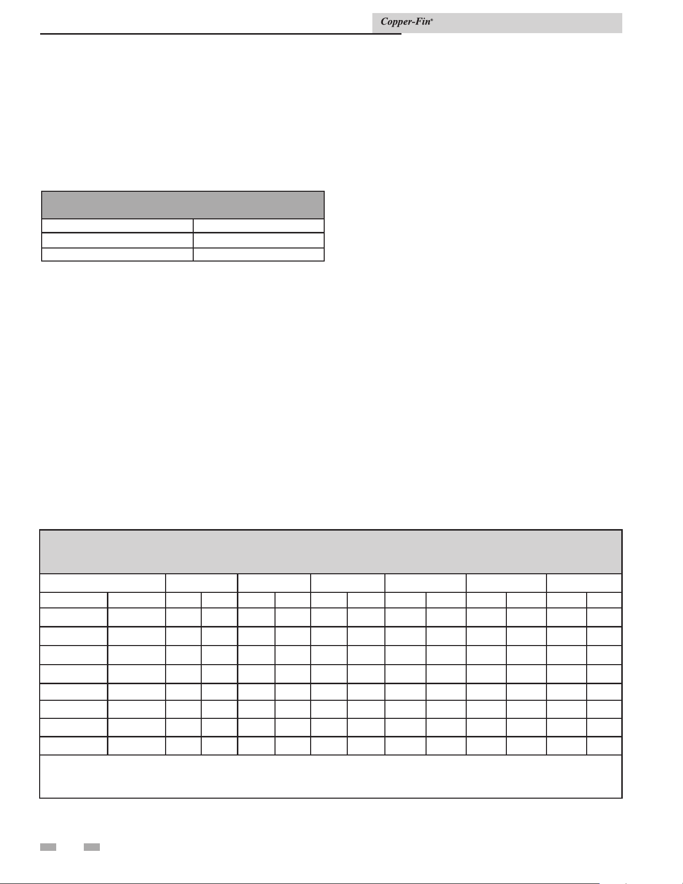
4 Water connections
32
Low temperature return water systems
Any non-condensing boiler and venting system will develop
operational problems when exposed to inlet water temperatures
below 140°F. Lochinvar offers a low temperature protection
valve (LTV) that is factory preset to maintain 140°F inlet water
to the boiler regardless of the system return water temperature.
See Table 4A for available valve kits.
TABLE 4A
LTV VALVE KITS
MODEL LTV VALVE KIT
497 - 747 100172001
987 - 2067 100172000
Be sure to install the LTV valve per the piping diagrams
included with the kits. Alternatively, a bypass as shown in FIG.
4-6 may be piped into the system. This piping is like a primary/
secondary boiler installation with a bypass in the secondary
boiler piping. Inlet water temperatures below 140°F (60°C)
can excessively cool the products of combustion resulting in
condensation on the heat exchanger and in the flue.
Condensation can cause operational problems, bad combustion,
sooting, flue gas spillage and reduced service life of the vent
system and related components. The bypass allows part of the
boiler discharge water to be mixed with the cooler boiler return
water to increase the boiler inlet temperature above 140°F
(60°C). This should prevent the products of combustion from
condensing in most installations. The bypass should be fully sized
with a balancing valve to allow for proper adjustment. A valve
must also be provided on the boiler discharge, after the bypass.
Closing this discharge valve forces water through the bypass.
Start boiler adjustment with the bypass valve in the full open
position and the boiler discharge valve half open. A small
amount of the higher temperature boiler discharge water is
mixed with the system water to maintain the desired lower
system temperature. A remote low temperature range operator
is recommended to control the boiler operation based on the
lower system temperature. (See Terminal Strip Connection
Options starting on page 40).
Radiant floor and snow melt heating
systems
This type of heating boiler application operates in a low
temperature range which requires a boiler bypass as described
under the Low Temperature Bypass Requirements section. A
non-metallic rubber or plastic tubing installed in a radiant (in
floor) system must have an oxygen barrier to prevent oxygen
from entering the system through the walls of the installed
tubing. Excessive oxygen absorption into the system will result
in an accelerated rate of corrosion causing a sludge buildup.
This excessive corrosion will also damage the boiler and system
components. Sludge formed as the result of excessive oxygen
in the system can restrict water flow resulting in a premature
boiler failure. Any boiler damage due to excessive oxygenation
is non-warrantable.
TABLE 4B
SYSTEM TEMPERATURE RISE CHART
Temperature Rise Based on Boiler Input in Btu/hr
Btu/hr 10°F DT 20°F DT 30°F DT 40°F DT 50°F DT 60°F DT
Input Output GPM Ft/hd GPM Ft/hd GPM Ft/hd GPM Ft/hd GPM Ft/hd GPM Ft/hd
495,000 416,000 80+ * 40 4.0 27 1.6 20 0.6 16 0.6 13 0.6
645,000 542,000 129+ * 52 5.1 35 3.0 26 1.2 21 0.8 17 0.6
745,000 626,000 149+ * 60 * 40 4.0 30 1.6 24 1.2 20 0.7
985,000 827,000 197+ * 80 5.2 53 2.4 40 1.4 32 1.0 27 0.8
1,255,000 1,054,000 251+ * 102+ * 68 4.3 51 2.3 41 1.6 34 1.1
1,435,000 1,205,000 288+ * 116+ * 78 6.0 58 3.7 47 2.2 39 1.7
1,795,000 1,508,000 360+ * 146+ * 97+ * 73 6.2 58 4.2 49 2.4
2,065,000 1,735,000 414+ * 168+ * 112+ * 84 8.7 67 6.0 56 4.5
+ These flow rates exceed recommended flow rates of boiler. If these system temperature rises are used, an external piping bypass must be
installed.
*These foot head calculations exceed the maximum allowable flow rate of the boiler. Requires Cupro-Nickel heat exchanger.
Installation & Service Manual
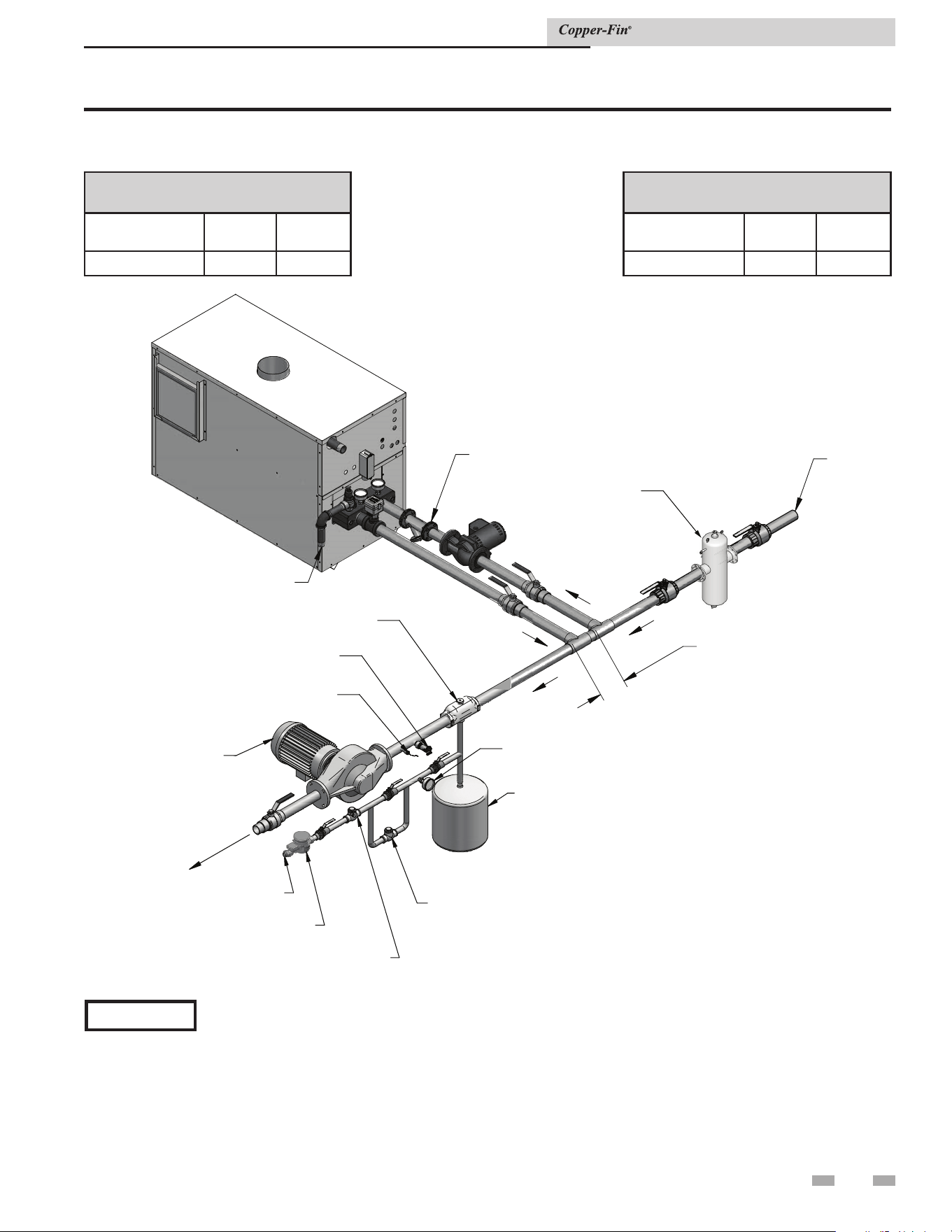
TO
FLOOR
DRAIN
HEATIN
G
RETURN
LOOP
12"
MAX
EXPANSION TANK
AIR SEPARATOR
PRESSURE REDUCING
VALVE
BACK FLOW
PREVENTER
PRESSURE GAUGE
DRAIN POINT
(TYPICAL)
SYSTEM SUPPLY SENSOR
(WHEN USED)
SY
STEM CIRCULATOR
T
O
S
Y
S
T
E
M
MAKE UP WATER
WATER METER
Y-STRAINER
DIR #2000570586_000
DIRT SEPARATOR
(RECOMMENDED)
33
4 Water connections (continued)
Figure 4-5_Primary/secondary piping of single boiler
Installation & Service Manual
COMMON MANIFOLD SIZE (Min.)
Models: 497 - 747
Number of Units GPM
Diameter
(in.)
1 60 2
COMMON MANIFOLD SIZE (Min.)
Models: 987 - 2067
Number of Units GPM
Diameter
(in.)
1 90 2 1/2
*Please note that these illustrations are meant to show system piping concept only, the installer is responsible
for all equipment and detailing required by local codes.
NOTICE
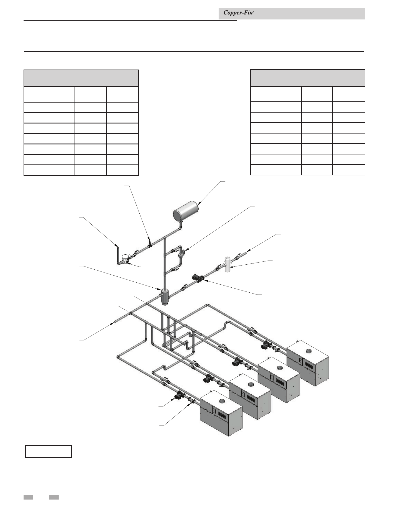
34
4 Water connections
Installation & Service Manual
Figure 4-6_Primary/secondary piping of multiple boilers
SECONDARY
BOILER
PUMP
FROM
SYSTEM
12" OR 4X
PIPE DIAMETERS
AIR
SEPARATOR
MAKE-UP
WATER
PRESSURE
RELIEF
VALVE
EXPANSION
TANK
LOW WATER
CUT-OFF
(OPTIONAL)
TO SYSTEM
SYSTEM
PUMP
WATER
METER
Y-STRAINER
(TYPICAL)
DIR #2000570587_000
DIRT SEPARATOR
(RECOMMENDED)
COMMON MANIFOLD SIZE (Min.)
Models: 497 - 747
Number of Units GPM
Diameter
(in.)
2 120 3
3 180 3 1/2
4 240 4
5 300 5
6 360 5
7 420 6
8 480 6
COMMON MANIFOLD SIZE (Min.)
Models: 987 - 2067
Number of Units GPM
Diameter
(in.)
2 180 4
3 270 5
4 360 6
5 450 6
6 540 6
7 630 8
8 720 8
*Please note that these illustrations are meant to show system piping concept only, the installer is responsible
for all equipment and detailing required by local codes.
NOTICE
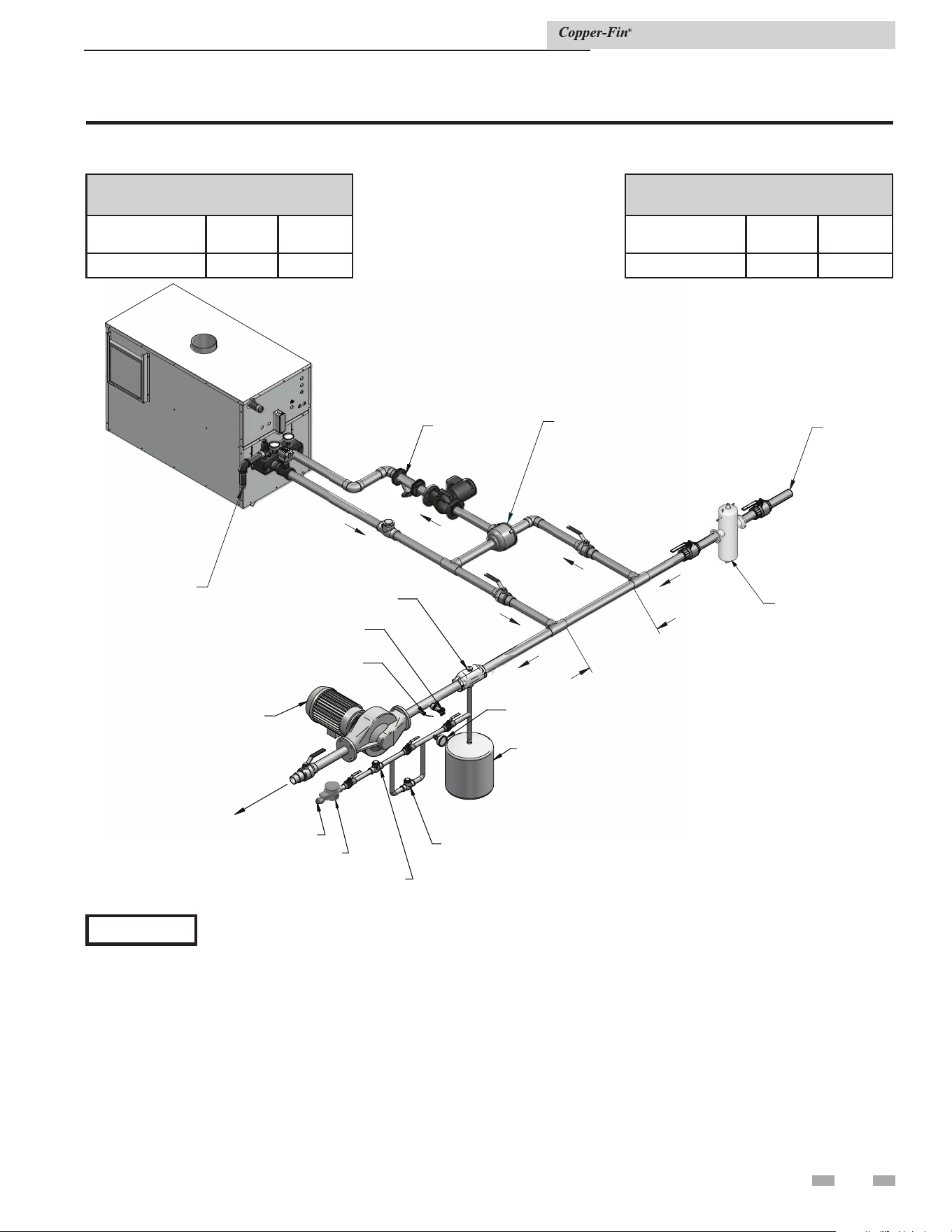
35
12”
EXPANSION TANK
AIR SEPARATOR
PRESSURE REDUCING
VALVE
BACK FLOW
PREVENTER
PRESSURE GAUGE
DRAIN POINT
(TYPICAL)
SYSTEM SUPPLY SENSOR
(WHEN USED)
SYSTEM CIRCULATOR
T
O
S
Y
S
T
E
M
MAKE UP WATER
WATER METER
Y-STRAINER
MIXING
VALVE
HEATING
RETURN
LOOP
TO
FLOOR
DRAIN
DIR #2000570588_000
DIRT SEPARATOR
(RECOMMENDED)
Figure 4-7_Boiler with low temperature bypass
*Please note that these illustrations are meant to show system piping concept only, the installer is responsible
for all equipment and detailing required by local codes.
NOTICE
4 Water connections (continued)
Installation & Service Manual
COMMON MANIFOLD SIZE (Min.)
Models: 497 - 747
Number of Units GPM
Diameter
(in.)
1 60 2
COMMON MANIFOLD SIZE (Min.)
Models: 987 - 2067
Number of Units GPM
Diameter
(in.)
1 90 2 1/2
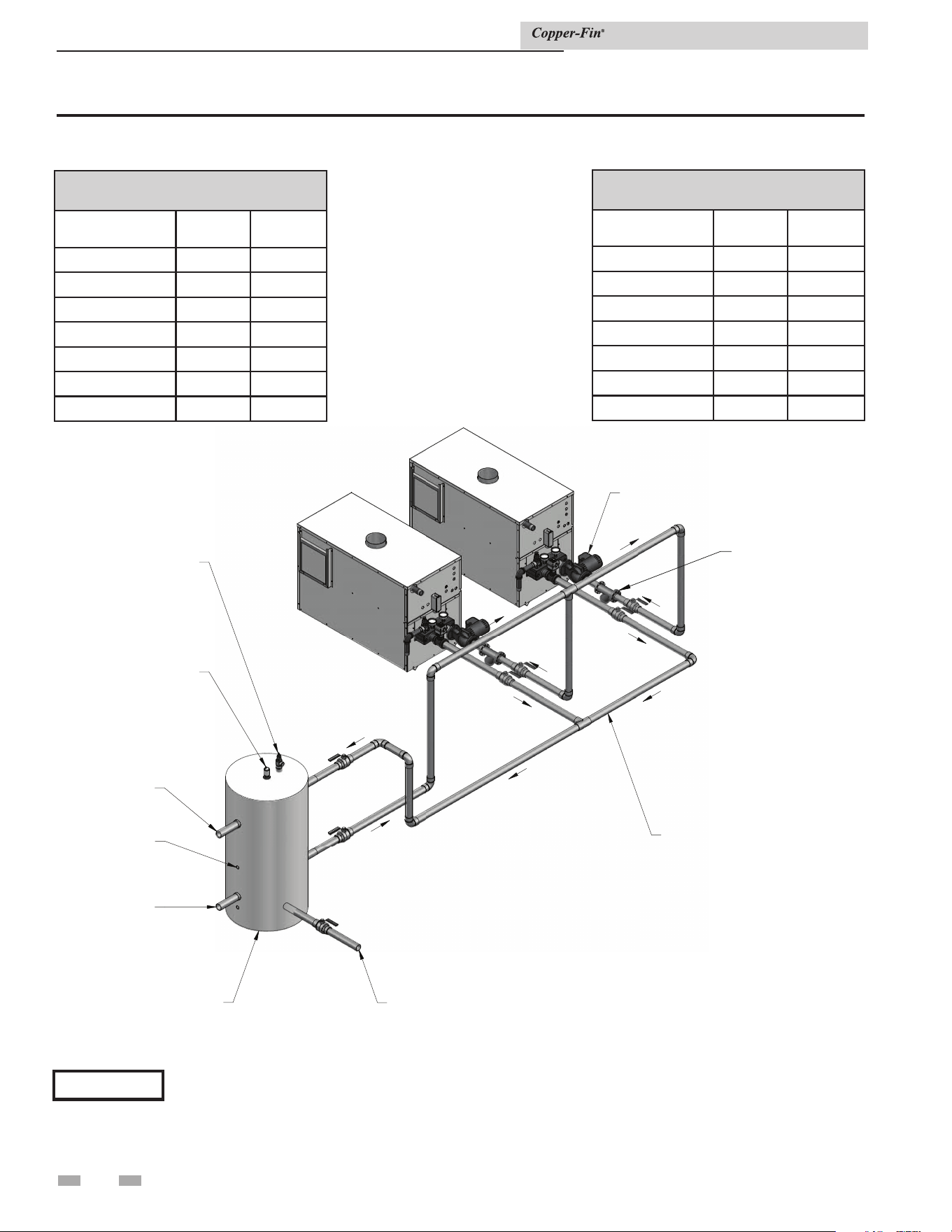
36
DIR #2000548442 00
1" TEMPERATURE
AND PRESSURE
GAUGE
AUTOMATIC AIR
ELIMINATOR/VENT
SYSTEM
OUTLET
SYSTEM
SENSOR
LOCATION
SYSTEM
INLET
BUFFER
TANK
DRAIN
PUMP
COMMOM MANIFOLD
MUST BE SIZED TO
ACCOMMODATE COMBINED
FLOW RATE FOR
ALL BOILERS
Y-STRAINER
(TYPICAL)
Figure 4-8_Primary/secondary piping with buffer tank
*Please note that these illustrations are meant to show system piping concept only, the installer is responsible
for all equipment and detailing required by local codes.
NOTICE
Installation & Service Manual
4 Water connections
COMMON MANIFOLD SIZE (Min.)
Models: 497 - 747
Number of Units GPM
Diameter
(in.)
2 120 3
3 180 3 1/2
4 240 4
5 300 5
6 360 5
7 420 6
8 480 6
COMMON MANIFOLD SIZE (Min.)
Models: 987 - 2067
Number of Units GPM
Diameter
(in.)
2 180 4
3 270 5
4 360 6
5 450 6
6 540 6
7 630 8
8 720 8
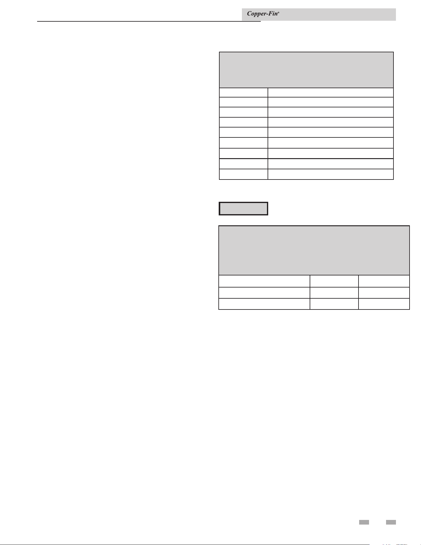
37
4 Water connections (continued)
Installation with a chilled water
system
Pipe refrigeration systems in parallel. Install duct coil
downstream at cooling coil. Where the hot water heating
boiler is connected to a heating coil located in the air handling
units which may be exposed to refrigeration air circulation, the
boiler piping system must be equipped with flow control valves
or other automatic means to prevent gravity circulation of the
boiler water during the cooling cycle.
The coil must be vented at the high point and hot water from the
boiler must enter the coil at this point. Due to the fast heating
capacity of the boiler, it is not necessary to provide a ductstat to
delay circulator operation. Also, omit thermostat flow checks
as the boiler is cold when heating thermostat is satisfied. This
provides greater economy over maintaining standby heat.
Boiler flow rate
Typical heating boiler installations
General plumbing rules:
1. Check all local codes.
2. For serviceability of boiler, always install unions.
3. Always pipe pressure relief valve to an open drain.
4. Locate system air vents at highest point of system.
5. Expansion tank must be installed near the boiler and on the
suction side of the system pump.
6. Support all water piping.
⚠ CAUTION
Do not exceed the maximum flow rate of the
heating boiler.
The heat exchanger is generally capable of operating within
the design flow rates of the building heating system. Should
the flow rate exceed the maximum allowable flow rate through
the boiler an external bypass must be installed. The bypass
should be fully sized with a balancing valve to allow for proper
adjustment of flow. Flow rate can be determined by measuring
the temperature rise through the boiler.
Installation & Service Manual
TABLE - 4C
BOILER TEMPERATURE RISE AT MAXIMUM FLOW
Temperature Rise at Full Rate Fire
Maximum Flow
Model Temperature Rise °F
497 15 @ 55 GPM
647 20 @ 55 GPM
747 23 @ 55 GPM
987 19 @ 90 GPM
1257 24 @ 90 GPM
1437 27 @ 90 GPM
1797 34 @ 90 GPM
2067 39 @ 90 GPM
TABLE - 4D
MAXIMUM WATER FLOW
The maximum flow rate through a water heater with
a copper heat exchanger must be set to provide and not exceed
the following flow:
Model Maximum Flow
Maximum Flow for
CuNi Heat Exchanger
497, 647, and 747 55 GPM 75 GPM
987, 1257, 1437, 1797, and 2067 90 GPM 115 GPM
⚠ CAUTION:

38
4 Water connections
The installer must ensure that the boiler is supplied with
adequate flow without excessive temperature rise. It is
recommended that this boiler be installed with a bypass in the
piping if the maximum recommended flow rate is exceeded.
The bypass will help to ensure that the boiler can be supplied
with adequate water flow. Flow rates exceeding the maximum
recommended flow will result in erosion of the boiler tubes.
A typical bypass with a valve as shown in FIG. 4-6 will allow
control of boiler flow.
Boiler bypass requirements
Temperature / pressure gauge
This boiler is equipped with a dial type temperature / pressure
gauge. This gauge is factory installed in the outlet side of the
boiler piping. The gauge has one scale to read system pressure
and a separate scale to read water temperature in degrees
Fahrenheit. The temperature / pressure gauge is provided to
meet code requirements. Water temperatures can be more
accurately monitored from the data provided in the digital
display in the Operator Interface.
All air must be purged from the system for proper operation.
An air scoop and air vent must be located close to the boiler
outlet and there should be a minimum distance between the
cold water feed and the system purge valve.
1. Close all drain cocks and air vents.
2. Open the makeup water valve and slowly fill the
system.
3. If a makeup water pump is employed, adjust the
pressure to provide a minimum of 12 psi at the highest
point in the system. If a pressure regulator is also
installed in the line, it should be adjusted to the same
pressure.
4. Close all valves. Purge one circuit at a time as follows:
A. Open one circuit drain valve and let the water
drain for at least five minutes. Ensure that
there are no air bubbles visible in the water
stream before closing the drain valve.
B. Repeat this procedure for each circuit.
5. Open all valves after all circuits have been purged.
Make sure there are no system leaks.
Filling the system
⚠ CAUTION
Do not use petroleum based stop leak
products. All system leaks must be repaired.
The constant addition of make-up water can
cause damage to the boiler heat exchanger
due to scale accumulation. Scale reduces
flow and heat transfer, causing overheating
of the heat exchanger.
6. Run the system circulating pump for a minimum of 30
minutes with the boiler turned off.
7. Open all strainers in the system and check for debris.
8. Recheck all air vents as described in step 4.
9. Inspect the liquid level in the expansion tank. The system
must be full and under normal operating pressure to
ensure proper water level in the expansion tank. Ensure
that diaphragm type expansion tanks are properly charged
and not water logged.
10. Start the boiler according to the operating instructions in
this manual. Operate the system, including the pump,
boiler and radiation units, for one hour.
11. Recheck the water level in the expansion tank. If it exceeds
half the tank volume, open the tank to reduce the water
level. Recheck pressure charge on diaphragm type tanks.
12. Shut down the entire system and vent all radiation units
and high points in the system.
13. Close the water makeup valve and check the strainer and
pressure reducing valve for sediment or debris. Reopen
the water makeup valve.
14. Verify system pressure with the boiler pressure gauge
before beginning regular operation.
15. Within three days of startup, recheck and bleed all air
vents and the expansion tank using these instructions.
Water treatment
In hard water areas, water treatment should be used to reduce
the introduction of minerals to the system. Minerals in the
water can collect in the heat exchanger tubes and cause noise on
operation. Excessive build up of minerals in the heat exchanger
can cause a non-warrantable failure.
Installation & Service Manual
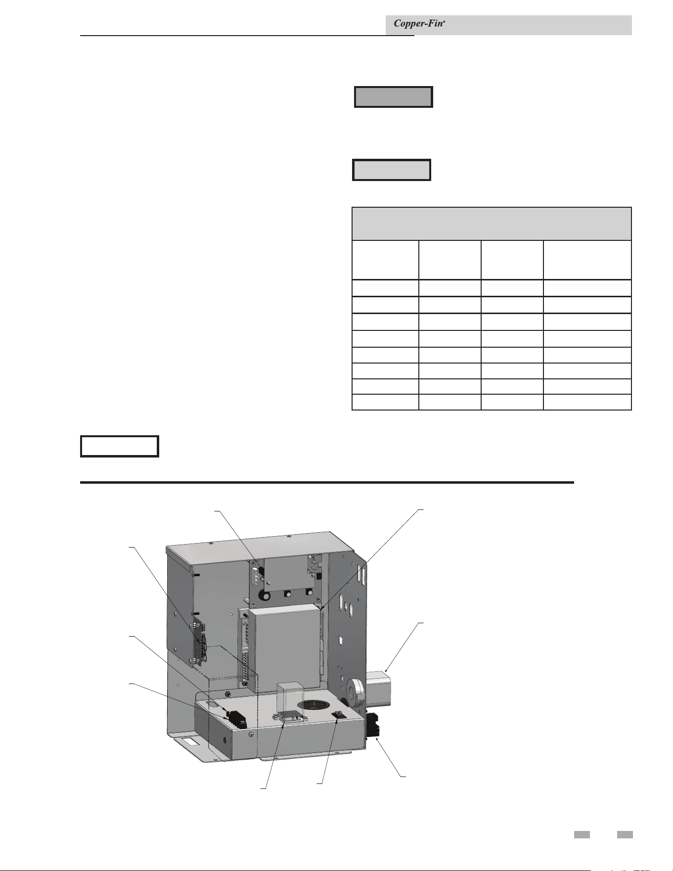
39
5 Electrical connections
Connecting to electrical supply
This unit is wired for 120 VAC service. The unit, when
installed, must be electrically grounded in accordance with
the requirements of the authority having jurisdiction or in
the absence of such requirements, with the latest edition of
the National Electrical Code ANSI/NFPA No. 70. When
the unit is installed in Canada, it must conform to the
CAE C22.1, Canadian Electrical Code, Part 1 and/or local
Electrical Codes.
1. Use only Type-T wire [63°F (35°C) rise] on all wiring
between the unit and field-installed devices.
2. Enclose line voltage wire exterior to the unit in approved
conduit or approved metal-clad cable.
3. The pump must run continuously when the unit is
being fired (water heaters must use the pump delay if
the pump is to be cycled. See Freeze Protection, page 11
when cycling the pump). Water heaters use the
pump delay as standard in accordance with ASHRAE
90.1 requirements.
4. To avoid serious damage, do not energize the unit until the
system is filled with water.
5. Provide the unit with proper overload protection.
NOTICE
Do not block access to the electrical
cover plate when installing electrical
conduit.
TABLE 5A
AMP DRAW DATA
Model Controls Fan
Approximate
Total Amps @
120 VAC
497 4.6 3.4 8.0
647 4.6 3.4 8.0
747 4.6 3.4 8.0
987 4.6 3.4 8.0
1257 4.6 3.4 8.0
1437 4.6 3.8 8.4
1797 4.6 3.8 8.4
2067 4.6 3.8 8.4
MANUAL
RESET
HIGH LIMIT
24 VDC
COIL
RELAY
GROUND
SCREW
CONNECT
ION
BOARD
TERMINAL
STRIP
24 VAC
RELAY
ON/OFF
SWITCH
IGNITION
MODULE
TWO STAGE
THERMOSTAT
Figure 5-1_Control panel location
ELECTRICAL SHOCK HAZARD – For your
safety, turn off electrical power supply before
making any electrical connections to avoid
possible electric shock hazard. Failure to do
so can cause severe personal injury or death.
⚠ WARNING
Label all wires prior to disconnection when
servicing controls. Wiring errors can cause
improper and dangerous operation.
⚠ CAUTION
Installation & Service Manual
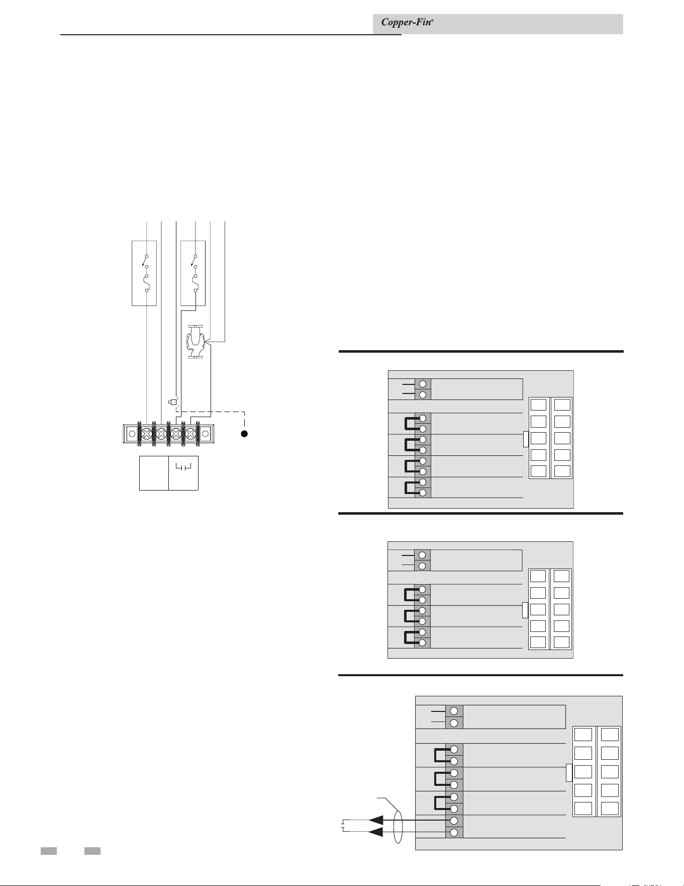
40
5 Electrical connections
External EMS connection to terminal
strip for stage firing control of burners
This unit is equipped with a factory installed terminal strip
for connection of an energy management system (EMS) to the
burner stages. The EMS terminal strip is located in the unit’s
control panel. Ensure that all wiring used for connection to
this terminal strip is properly sized per the recommendations
in TABLE 5A. When connecting an EMS to this terminal
strip to sequence on each stage of burner operation, the unit’s
internal thermostat or electronic sequencer should be set as
an additional high limit control. This will prevent problems
between the set points of the EMS and the boiler’s internal
controller.
wiring connections. This remote ON/OFF control will provide
an Enable/Disable signal to the unit and allow the unit to
operate based on the stage set points, until the remote ON/OFF
signal is cancelled.
Figure 5-7 shows the connections necessary to operate the unit
as a two-stage (High/Low Fire) boiler or water heater from
an Energy Management System (EMS). The actual set point
temperatures are controlled by the EMS. The High Fire Offset
on the electronic temperature control in the unit must be set to
zero and the set point must be set to a value which will function
as an upper limit for proper operation under this two-stage
control from an EMS.
Figure 5-8 shows the Continuous and Intermittent terminals.
External safety devices connected to these terminals will function
to protect the unit. Devices connected to the Intermittent
terminals (B1 and B2) are monitored only when there is an
active Call for Heat. Devices connected to the Continuous
terminals (A1 and A2) are monitored continuously and will
activate an alarm (if the unit is equipped with the alarm option)
anytime the safety device senses an abnormal condition.
1
2
3
4
5
6
7
8
9
10
+
+
+
+
+
+
+
+
+
+
SYSTEM/TANK
SENSOR
B2
B1
A2
A1
2NO
2C
1NO
1C
INTERMITTENT
LIMITS
CONTINUOUS
LIMITS
HIGH FIRE
ENABLE
LOW FIRE
ENABLE
9
8
7
6
4
3
2
1
10 5
1
2
3
4
5
6
7
8
9
10
+
+
+
+
+
+
+
+
+
+
SYSTEM/TANK
SENSOR
B2
B1
A2
A1
2NO
2C
1NO
1C
INTERMITTENT
LIMITS
CONTINUOUS
LIMITS
HIGH FIRE
ENABLE
LOWFIRE
ENABLE
9
8
7
6
4
3
2
1
10 5
Remote
on/off
Figure 5-3_Stand-alone operation boiler
Figure 5-5_Remote on/off boiler
Installation & Service Manual
Line voltage connections
1. Connect 120 VAC power wiring to the line voltage terminal
strip in the junction box, as shown in FIG. 5-2.
2. Provide and install a fused disconnect or service switch
(15 AMP recommended) as required by the code (see
FIG. 5-2).
3. To activate a system pump, wire as shown in FIG. 5-2. If
the motor is larger than 1 HP, you must install a contactor.
IMG00594
G
D
I
S
C
O
N
N
E
C
T
LN
120V
SUPPLY
UNIT
PUMP
1 HP MAX
LBL20174 REV A
UNIT
PUMP
D
I
S
C
O
N
N
E
C
T
GNLNL
UNIT
SUPPLY
UNIT PUMP
SUPPLY
GROUND
SPLICE
CHASSIS
GROUND
Figure 5-2_Line Voltage Field Wiring Connections
Terminal strip connection options
Figures 5-3 and 5-4 show the position of jumpers as shipped
from the factory for stand-alone operation of boilers or water
heaters.
Figures 5-5 and 5-6 show connections to the terminal strip for
Remote ON/OFF control of the boiler or water heater. The
1C-1NO jumper must be removed when making these
1
2
3
4
5
6
7
8
+
+
+
+
+
+
+
+
SYSTEM/TANK
SENSOR
B2
B1
A2
A1
NO
C
1
1
INTERMITTENT
LIMITS
CONTINUOUS
LIMITS
ENABLE
9
8
7
6
4
3
2
1
10 5
Figure 5-4_Stand-alone operation water heater
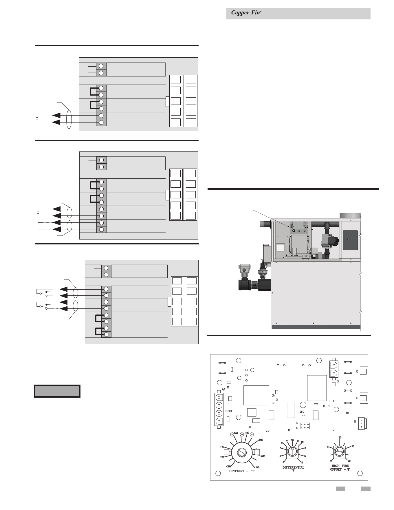
41
5 Electrical connections (continued)
Temperature adjustment
Note: The temperature controller is preset at the factory with
test settings. You may need to adjust the settings to meet your
specific needs.
Return water temperatures must not be less
than 140°F. If lower return water temperatures
are required, follow the instructions for Low
Temperature Return Water Systems on page
32.
⚠ WARNING
Locating the temperature control
The temperature control is located behind the panel on the left
front of the unit (see FIG. 5-9). Follow the steps below to access
the temperature control.
1. Loosen the knurled knob at the bottom of the control
panel cover.
2. Pull the bottom of the panel out and down to remove.
Temperature control settings
There are three setting knobs on the temperature control unless
your unit is specified as a boiler only with an outdoor air reset
option. If your unit is a boiler only with an outdoor air reset
option, there are additional controls for this option. They are
explained under Outdoor Air Reset Option, page 42.
The three setting knobs on the temperature control are for Set
Point, Differential, and High-Fire Offset (see FIG. 5-10).
Maximum set point
The maximum set point for the control is factory set. Boilers
are set to 230°F max., water heaters are set to 190°F max., and
specialty state and local codes to 200°F.
These maximum set points are established by not cutting/
cutting the OJ1 and OJ2 jumpers located on the right side of the
temperature controller (see FIG. 5-10). The maximum set point
is determined as shown in Table 5B.
Figure 5-9_Locating temperature control
TEMPERATURE
CONTROL
Figure 5-10_Temperature control setting knobs
VR3VR2VR1
CN8
CN7
CN9CN1
CN2
CN4
CN3
CN6
CN5
DIR #2000571961 00
Installation & Service Manual
Stage 1
1
2
3
4
5
6
7
8
9
10
+
+
+
+
+
+
+
+
+
+
SYSTEM/TANK
SENSOR
B2
B1
A2
A1
2NO
2C
1NO
1C
INTERMITTENT
LIMITS
CONTINUOUS
LIMITS
HIGH FIRE
ENABLE
LOW FIRE
ENABLE
9
8
7
6
4
3
2
1
10 5
Stage
2
Continuous
Alarms
1
2
3
4
5
6
7
8
9
10
+
+
+
+
+
+
+
+
+
+
SYSTEM/TANK
SENSOR
B2
B1
A2
A1
2NO
2C
1NO
1C
INTERMITTENT
LIMITS
CONTINUOUS
LIMITS
HIGH FIRE
ENABLE
LOW FIRE
ENABLE
9
8
7
6
4
3
2
1
10 5
Intermittent
Alarms
Figure 5-8_Field installation safety devices
Figure 5-7_Two-stage (high/low fire) boiler
1
2
3
4
5
6
7
8
+
+
+
+
+
+
+
+
SYSTEM/TANK
SENSOR
B2
B1
A2
A1
1NO
1C
INTERMITTENT
LIMITS
CONTINUOUS
LIMITS
ENABLE
9
8
7
6
4
3
2
1
10 5
Remote
on/off
Figure 5-6_Remote on/off water heater
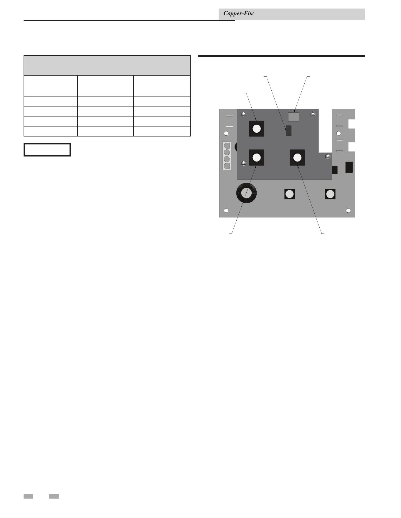
42
5 Electrical connections
TABLE 5B
Maximum Setpoint Determination
OJ1 OJ2
Max.
Setpoint
Connected Connected 230°
Cut Connected 190°
Connected Cut 200°
Cut Cut 160°
NOTICE
Anytime that OJ1 is the only jumper cut, a
new overlay is required under the Set Point
knob on the temperature controller because
the scale has changed to a maximum of
190°F.
Anytime the OJ2 jumper is cut (with or
without OJ1), a new overlay is required
under the Set Point knob on the temperature
controller because the scale has changed to
a maximum of 200°F.
Setpoint
The Set Point knob specifies the target water temperature in
degrees, Fahrenheit. After the water temperature reaches the set
point, the temperature control shuts off the burners.
Differential
The Differential specifies the number of degrees below the set
point that the control will allow the water temperature to drop
before it brings the unit back on again.
Installation & Service Manual
High-fire offset
The temperature control operates a two-stage firing system.
The two stages are High-Fire and Low-Fire. High-Fire operates
all burners while Low-Fire operates approximately one-half of
the burners.
The High-Fire knob specifies the number of degrees below set
point that the High-Fire stage shuts down. At that point, the
unit will continue to operate at the Low-Fire stage until the set
point is reached.
The High-Fire offset knob has settings between 0°F and 20°F.
If set at 0°F, the High-Fire offset is disabled and the unit will
operate at the High-Fire stage until the set point is reached and
the temperature control shuts the unit off.
When the High-Fire offset knob is set to 0 or 1, the unit will
light at Low Fire and operate for approximately 10 seconds
before the High-Fire stage actuates. When set to 2 or above, the
unit will operate at Low Fire for approximately 2 minutes before
the High Fire stage can actuate.
Figure 5-11_Optional outdoor reset control
OUTDOOR
AIR
SHUTDOWN
SHUTDOWN
OUTDOOR
AIR
SENSOR
RATIOOUTDOOR
AIR
MAX
Outdoor reset option
For boilers ordered with the Outdoor Air Reset option, there
is an additional control (see FIG. 5-11). There are three setting
knobs for Shutdown, Outdoor Air Max., and Ratio. There is
also a switch to turn the outdoor air sensor On or Off. An O.A.
Sensor is also included.
Shutdown
The Shutdown knob specifies the outdoor air shutdown
temperature at which the control would prevent the unit from
operating. This feature can be enabled/disabled with the O.A.
Shutdown switch.
Outdoor air max (O. A. Max)
The O. A. Max knob allows a reset up to the maximum outdoor
air temperature specified by this knob setting. When the
outdoor air temperature is above the specified setting, the unit
will not function in the O.A. Reset Mode, but will continue to
run at the selected set point temperature.
Note that the set point knob will now indicate the “minimum”
boiler temperature. Target temperature is determined by the
ratio and outdoor air temperature below the O.A. Max setting.
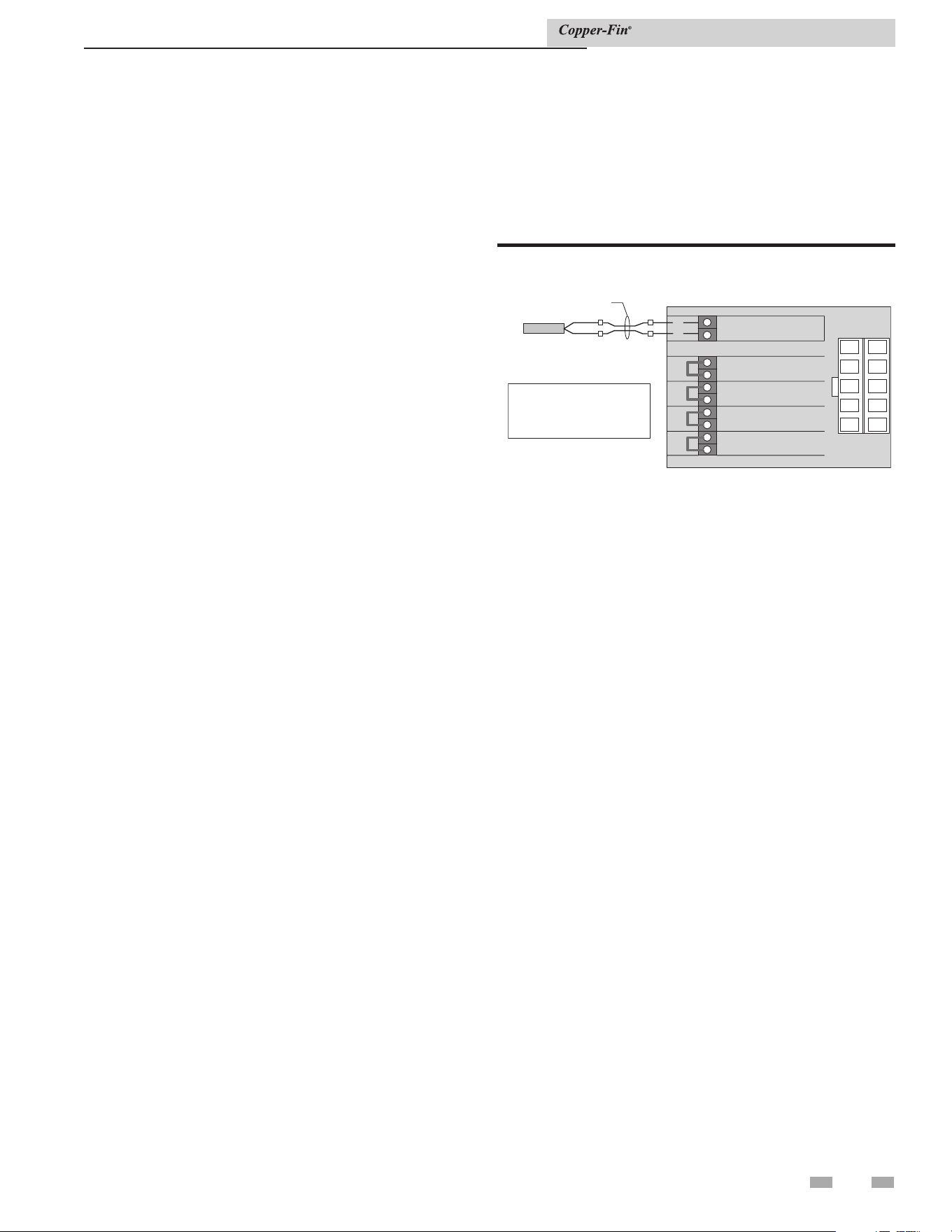
43
5 Electrical connections (continued)
Temperature control sensors
This is a two-stage temperature control that controls the
burner ignition, pump, and alarm functions. This temperature
controller can measure up to three different sensor inputs,
depending upon how the unit is set up. They are as follows:
1. Inlet Water Temperature Sensor
2. Multi-Purpose Temperature Sensor
3. Outside Air Temperature Sensor
Inlet water temperature sensor
This sensor measures the inlet water temperature coming into
the unit.
Multi-purpose temperature sensor
This sensor can be used as a system sensor or a tank sensor.
Outdoor air temperature sensor
This sensor is only available on boiler units with an outdoor
air reset option. This allows you to tie boiler operation to the
outdoor air temperature. As outside temperatures drop, the
control will increase the temperature setting of the boiler.
As outdoor temperatures rise, the control will decrease the
temperature to the selected set point of the boiler. You can set
the control to shut the boiler off when a desired outdoor air
temperature level is reached.
Installation & Service Manual
Boiler application
Standard boiler units are shipped with two sensors; the inlet
water temperature sensor and the multi-purpose temperature
sensor. The multi-purpose sensor should be used as a system
sensor. Boilers with the outdoor air reset option also have an
outside air temperature sensor.
Water heater application
Water heater units are shipped with two sensors; the inlet water
temperature sensor and the multi-purpose temperature sensor
to be used as a tank sensor.
Placement of sensors
Inlet temperature sensor
The inlet water temperature sensor is installed by the factory
in new units. The sensor is an immersion style and maintains
direct contact with the water.
System sensor
This is used for boiler applications. This sensor will control the
boiler operation based upon the water temperature within the
building loop.
Tank sensor
This is used in water heating applications. Place the sensor in
the water storage tank to measure water temperature. For more
information on mounting the sensor, see Remote Mounting of a
Sensor, page 44.
Remote sensor for pump delay
This appliance is provided with a special thermostat sensor
that MUST be field installed. The sensor is shipped loose in
the I & O packet. This remote mounted sensor will be the
primary water sensor which will inform the appliance's built-
in thermostat control. Reading the water temperature at the
remote location is required for proper operation of the pump
delay option provided with this appliance.
For domestic water heating, the sensor must be installed into a
bulbwell on the storage tank. For boiler and hydronic heating,
the sensor must be installed in the system piping loop. If the
appliance is controlled by a remote sequencer, the sensor must
be routed back into the appliance and placed in a bulbwell on
the inlet side of the heat exchanger.
FIELD SUPPLIED
WIRING
1
2
3
4
5
6
7
8
9
10
+
+
+
+
+
+
+
+
+
+
CONNECTIONBOARD
SYSTEM/TANK
SENSOR
B2
B1
A2
A1
2NO
2C
1NO
1C
INTERMITTENT
LIMITS
CONTINUOUS
LIMITS
HIGH FIRE
ENABLE
LOW FIRE
ENABLE
9
8
7
6
4
3
2
1
10 5
SYSTEM/
TANK
SENSOR
REQUIRED IN ORDER
FORPUMPDELAY TO
FUNCTION PROPERLY
Figure 5-12_Remote sensor for pump delay
Ratio
The Ratio knob allows the control over the reset ratio to be used
during Outdoor Air Reset. The allowable ratios are as low as
0.5:1 or as high as 1.5:1.
Selecting the 0.5:1 ratio will increase the set point 0.5°F for every
1.0°F drop in outdoor air temperature up to the maximum set
point temperature.
Selecting the 1.5:1 ratio will increase the set point 1.5°F for every
1.0°F drop in outdoor air temperature up to the maximum set
point temperature (see page 41).
See FIG. 5-13 for an outdoor air reset chart example.
The sensor must be connected to two wires provided on the side
of the appliance with the water connections (FIG. 5-12). It will
be necessary to add additional wire to reach from the appliance
to the remote water source. Use twisted pair wire or minimum
18 gauge wire or larger. Reference Table 5C on page 44 for a
chart regarding distance versus wire gauge.
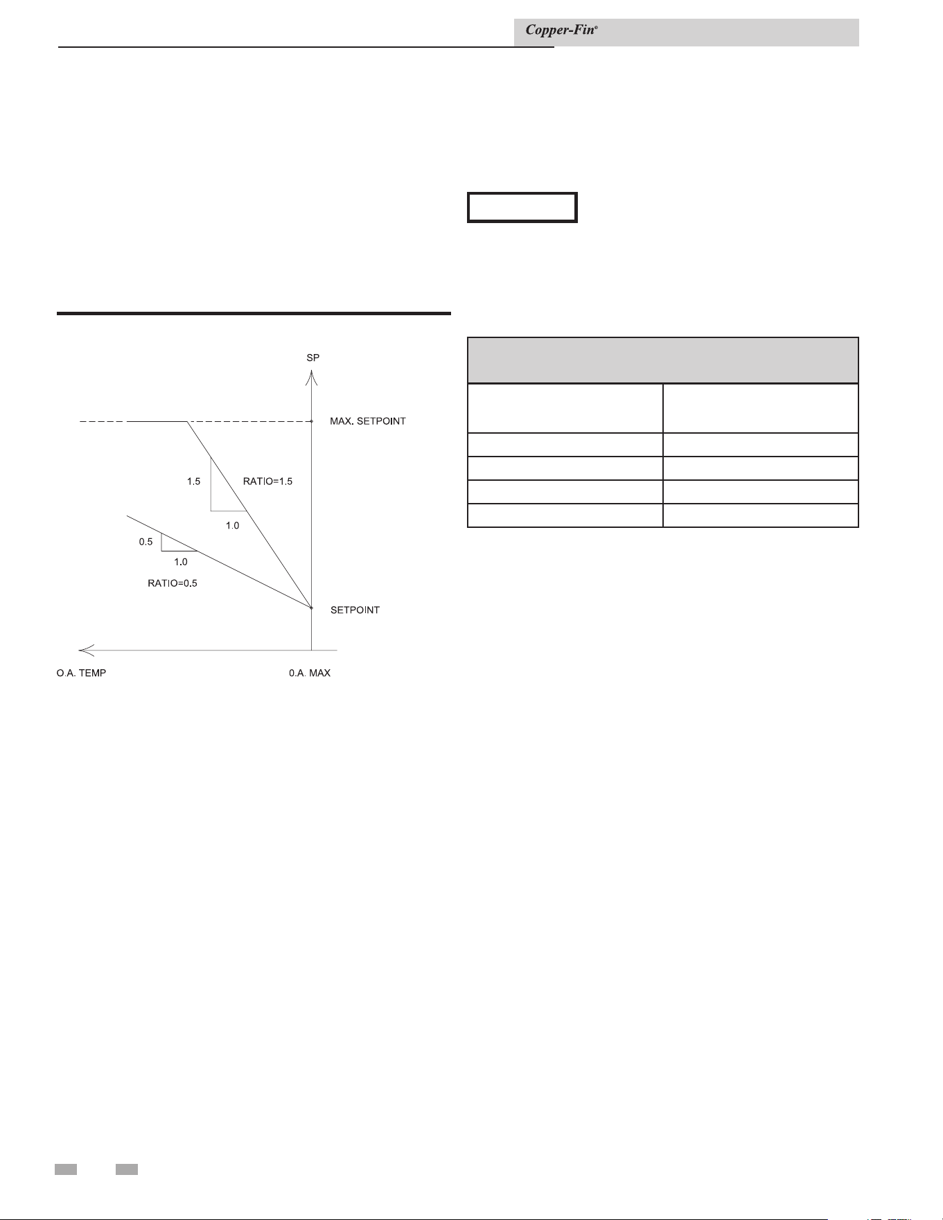
44
5 Electrical connections
Remote mounting of a sensor
You must mount the outside air temperature sensor outside
the building. To mount remote sensors, follow the guidelines
below. Take care to correctly wire sensors to the unit. Erratic
temperature readings can be caused by poor wiring practices.
Twist the wires between the unit and the remote sensor. Turn
wires at least three or four turns per linear foot of wiring. This
provides common mode rejection of some types of electrical
interferences.
1. Do not route temperature sensor wiring with building
power wiring.
2. Do not locate temperature sensor wiring next to control
contactors.
3. Do not locate temperature sensor wiring near electric
motors.
4. Do not locate temperature sensor wiring near welding
equipment.
5. Make sure good mechanical connections are made to the
sensor, any interconnecting wiring and the controller.
6. Do not mount sensor with leadwire end pointing up in an
area where condensation can occur.
Installation & Service Manual
Figure 5-13_Outdoor air reset chart example
Outdoor air Temperature sensor
The outside air temperature sensor will only be used for boiler
systems. The outside air sensor is optional. You must purchase
the sensor from the appliance manufacturer. The sensor comes
with a housing that helps protect the sensor from the elements.
Mount the air sensor housing under the eve of the roof. Make
sure the housing is out of direct sunlight. This will ensure that
the sensor will accurately read the true outdoor temperature.
For more information on mounting the sensor, see Remote
Mounting of a Sensor.
NOTICE
Ground the cable shield at the connection
to the boiler temperature control only. Do
not ground the shielded cable at the sensor
end.
To maintain temperature accuracy, sensor
wires should be at least 18 AWG, see Table
5C.
TABLE 5C
Remote Wire Connection
Wire Gauge Max. Allowable Length
12 GA 100 FT
14 GA 75 FT
16 GA 50 FT
18 GA 30 FT
7. Use shielded wiring to connect the sensor to the control
when the possibility of an electrically noisy environment
exists. Shielded cable is recommended on all cable runs of
more than 25 feet in length.
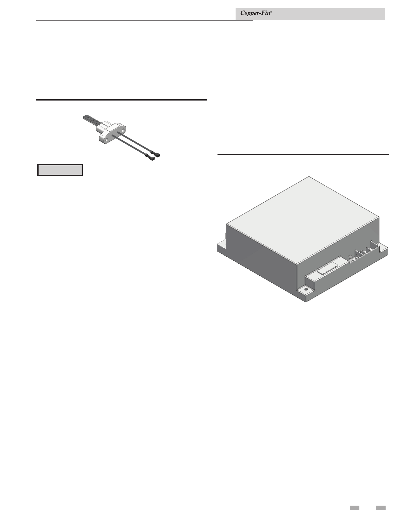
45
5 Electrical connections (continued)
Diagnostic Status Indication
The ignition module has an LED which indicates the status of the
safety circuits. A remote Ignition Module Status indicating light
is wired from the ignition module Status LED and mounted on
the front diagnostic panel. The flashing operation of this light
indicates the diagnostic status of the ignition control module.
The status LED, mounted on the ignition module flashes a code
sequence from the Ignition Module to indicate the status of the
ignition process. See Table 5D for the flashing diagnostic status
codes as signaled by the ignition module.
Figure 5-15_Hot surface ignition control module
Installation & Service Manual
Note: Flame current is typically 2 - 6 µA
Hot surface ignition system
Hot surface igniter and ignition control
module
This unit has one ignition module and one hot surface igniter.
Figure 5-14_Hot surface igniter
The igniter is extremely fragile, be very
careful when removing. A faulty or damaged
hot surface igniter MUST BE replaced with
a Lochinvar PLT3400 igniter. Do not use
general purpose field replacement igniters.
⚠ CAUTION
Hot surface ignition control module
Ignition Module Lockout Functions
The ignition module may lockout in either a hard-lockout
condition, requiring pushing of the reset button to recycle
the control, or a soft-lockout condition which may recycle
after an approximate five-minute waiting period. This soft-
lockout condition is intended to allow self-correcting faults
to correct themselves and permit normal operation. A typical
hard-lockout fault is a flame failure condition. An ignition
module that is in a hard-lockout condition may only be reset
by pushing the reset button next to the ignition control or the
“RESET” button on the diagnostic panel on the left end of
the unit. Upon a flame failure, the reset button is only active
after the control module has completed its post-purge cycle.
Turning main power “OFF” and then “ON” or cycling the
thermostat will not reset a hard-lockout condition. Wait five
seconds after turning on main power before pushing the reset
button when the ignition module is in a hard lockout. The
ignition module will go into a soft lockout if conditions of low
air, low voltage or low hot surface igniter current are present.
A soft-lockout condition will operate the combustion air fans
for the post purge cycle and then the ignition module will
pause for approximately five minutes. At the end of this timed
pause, the ignition module will attempt a new trial for ignition
sequence. If the soft-lockout fault condition has subsided or
has been corrected at the end of the timed pause, main burner
ignition should be achieved with the resumption of the normal
trial for ignition sequence. If the control sensed fault is not
corrected, the ignition module will continue in the soft-lockout
condition. If the electronic thermostat opens during the soft-
lockout period, the ignition module will exit soft lockout and
wait for a new call for heat from the thermostat. A soft-lockout
condition may also be reset by manually cycling the thermostat
or turning the main power switch “OFF” and then “ON” after
the control sensed fault has been corrected.
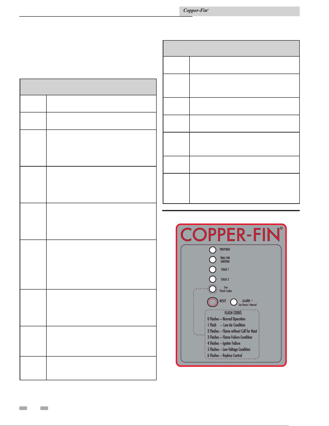
46
5 Electrical connections
Operation and diagnostic lights
The diagnostic control panel has up to 6 indicating and
diagnostic lights to show all major steps of operation and
control sensed malfunctions. This panel is located on the front
of the unit.
TABLE 5D
Status LED Diagnostic Codes
Code
Sequence
Condition
Constant
ON
System OK, no faults present.
Constant
OFF
Possible control fault, check power; LED may
be defective, do not replace control if all
operational sequences function properly, see
Trouble- Shooting Guide.
One
Flash
Low Air, check air pressure switch and hoses
to pressure sensing points, fan, venting and
sealing of pressurized chamber. Note: Brief
flashing normal on fan start-up proving.
Two
Flashes
Flame without call for heat, check for a gas
valve stuck in the open position, air, venting,
burners and the combustion process. Fan will
remain on.
Three
Flashes
Lockout due to flame failure, push reset
button on the diagnostic panel after correcting
ignition problem. Initial heater start up
without properly bleeding air from the gas
line may require multiple reset functions to
achieve proper ignition.
Four
Flashes
Igniter failure, igniter will not maintain a
minimum 2.75 amp current draw, caused
by low voltage, bad wiring/continuity, high
resistance or igniter failure.
Five
Flashes
Power supply problem, check for low supply
voltage or transformer output less than
18VAC.
Six
Flashes
Replace ignition module, internal fault.
TABLE 5E
Status LED Diagnostic Codes
Code
Sequence
Condition Lights
Prepurge
Operation for combustion air fan before ignition
on stages 1 and 2.
Trial for
Ignition
Hot surface igniter preparing to light burners.
Stage 1 ON Burners for stage 1 operating.
Stage 2 ON
Burners for stage 2 operating.
Status Remote status light for ignition module.
Alarm
Indicates flame failure on the ignition module
and will indicate additional alarms if the alarm
of any failure option is purchased.
Figure 5-16_Operation / diagnostic lights
Installation & Service Manual
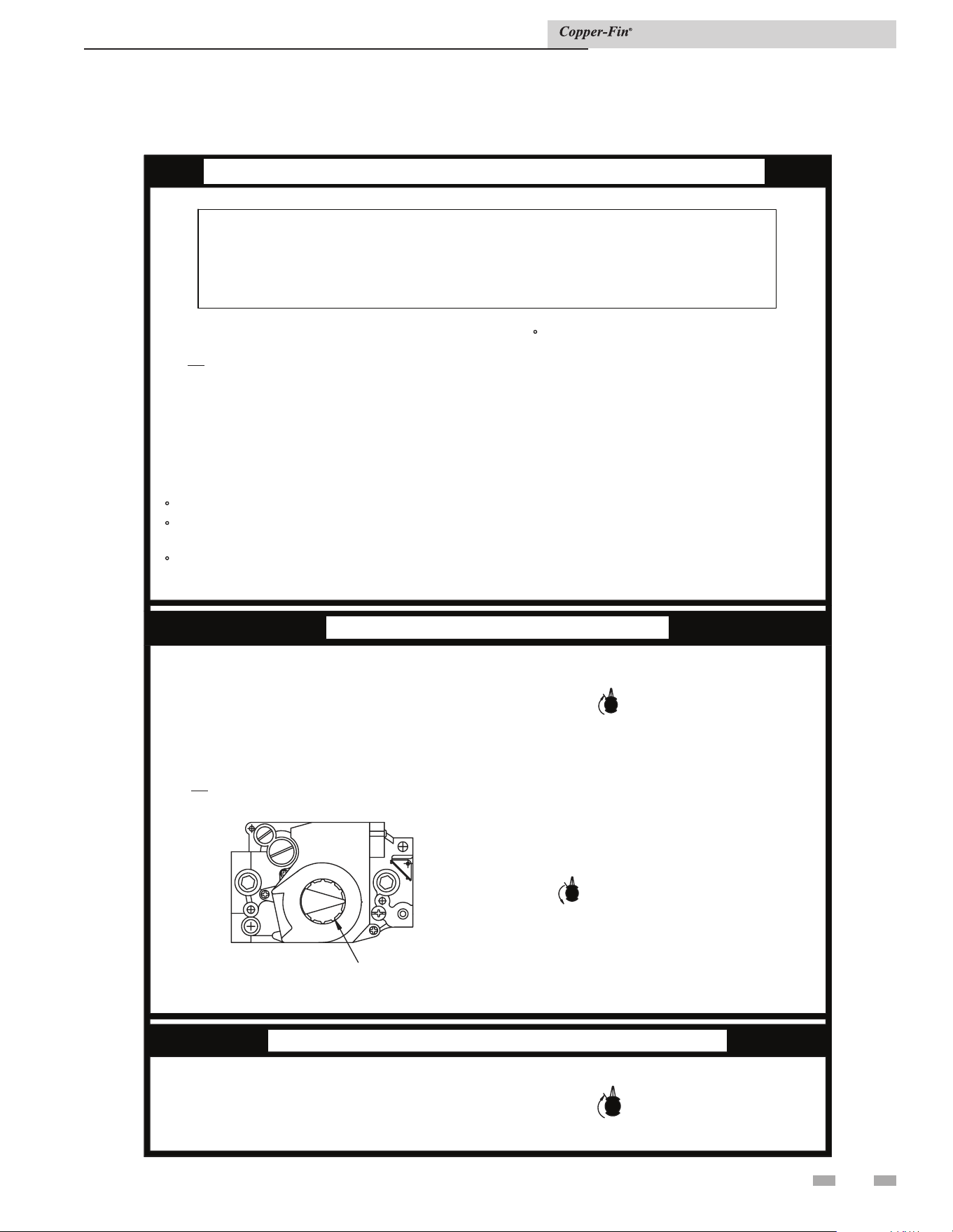
47
6 Startup
Figure 6-1_Operating instructions
Installation & Service Manual
FOR YOUR SAFETY READ BEFORE OPERATING
A. This appliance is equipped with an ignition
device which automatically lights the burner.
Do not
try to light the burner by hand.
B. BEFORE OPERATING smell all around the
appliance area for gas. Be sure to smell next
to the floor because some gas is heavier
than air and will settle on the floor.
FOR YOUR SAFETY
"WHAT TO DO IF YOU SMELL GAS"
Do not try to light any appliance.
Do not touch any electrical switch; do not use
any phone in your building.
Immediately call your gas supplier from a
neighbor's phone. Follow the gas supplier's
instructions.
If you cannot reach your gas supplier,
call the fire department.
C. Use only your hand to turn the gas
control knob. Never use tools. If the
knob will not turn by hand, don't try to
repair it, call a qualified service tech-
nician. Force or attempted repair may
result in a fire or explosion.
D. Do not use this appliance if any part
has been under water. Immediately call
a qualified service technician to inspect
the appliance and to replace any part
of the control system and any gas con-
trol which has been under water.
OPERATING INSTRUCTIONS
1. STOP! Read the safety information above on
this label.
2. Turn off all electric power to the appliance.
3. Open control access panel.
4. This appliance is equipped with an ignition
device which automatically lights the burner.
Do not
try to light the burner by hand.
5. Push in gas control knob slightly and
turn clockwise to "OFF."
NOTE: On the 36C valve, knob cannot be
turned to "OFF" unless knob is pushed in
slightly. Do not force.
7. Turn gas control knob counterclockwise
to "ON."
8. Replace control access panel.
9. Turn on all electric power to the appliance.
10. If the appliance will not operate, follow
the instructions "To Turn Off Gas To
Appliance" and call your service tech-
nician or gas supplier.
TO TURN OFF GAS TO APPLIANCE
1. Turn off all electric power to the appliance
if service is to be performed.
2. Open control access panel.
3. Push in gas control knob slightly and
turn clockwise to "OFF". Do not
force.
4. Replace control access panel.
ON
OFF
OFF
ON
LBL2084 REV D
OFF
ON
OFF
ON
PSI
IN
GAS CONTROL KNOB
SHOWN IN THE "ON" POSITION
6. Wait five (5) minutes to clear out any gas.
Then smell for gas, including near the floor. If
you smell gas, STOP! Follow "B" in the safety
information above on this label. If you don't
smell gas, go to the next step".
WARNING:
If you do not follow these instructions
exactly, a fire or explosion may result causing
property damage, personal injury or loss of life.
48
6 Startup
Installation & Service Manual
Check/control fill water chemistry
Conduct water quality testing prior to
installing the appliance. Various solutions
are available to adjust water quality.
Hardness between 5 and 15 grains per gallon
1. Consult local water treatment companies for hard water
areas (above 15 grains per gallon hardness).
2. Hardness levels that are above 15 grains/gallon can lead
to lime scale buildup throughout the boiler system. If the
fill water is below 5 grains/gallons, usually due to use of a
water softener, it is recommended to mix in some potable
water at the inlet to increase the hardness of the water to
above 5 grains/gallons.
pH between 6.5 and 8.5
1. pH levels below 6.5 can cause an increase in the rate of
corrosion. pH of 8.5 or higher can potentially cause lime
scale buildup.
Total Dissolved Solids (TDS) less than 350 ppm
1. Total dissolved solids are all minerals, salts, metals, and
charged particles that are dissolved in water.
2. The greater the amounts of TDS present, the higher the
corrosion potential due to increased conductivity in the
water.
Chlorine concentration less than 150 ppm
1. Do not fill boiler or operate with water containing
chlorine in excess of 150 ppm.
2. Filling with fresh drinking water should be acceptable.
3. Do not use the boiler to directly heat swimming pool or
spa water.
IMPORTANT
Fill water
The manufacturer recommends the following for properly
filling your boiler with the appropriate water chemistry for
closed loop boilers. Good fill water quality will help extend
the life of the appliance by reducing the effects of lime scale
buildup and corrosion in closed loop systems.
Ethylene glycol is toxic, DO NOT use as
your freeze protection. Ethylene glycol has a
sweet aroma which children and pets could
mistake as food and ingest; leading to death.
⚠ WARNING
Pre-Commissioning Cleaning
1. Prior to fill and start-up, flush the entire heating system.
2. Clean the entire heating system with an approved pre-
commissioning cleaner (comparable to Sentinel X300
or Fernox F3) in accordance with the manufacturer’s
recommendation to remove debris and prolong the life of
the heat exchanger.
3. Clean all water filtering devices in the system.
4. Flush the cleaning solution out of the entire system and
refill.
Boiler water
BOILER WATER CHEMISTRY
Specication Range
Dissolved Solids < 2000 ppm
pH Level 6.5 to 9.5
Chloride < 150 ppm
• Monitoring pH, chlorides, TDS, and hardness
levels can prolong the life of the appliance by reducing
lime scale buildup, corrosion, and erosion. Check for
leaks to ensure that fresh water is not entering the
system.
• Continual fresh makeup water will reduce boiler life.
• Mineral buildup in the heat exchanger reduces heat
transfer, overheats the stainless steel heat exchanger,
and causes failure.
• The addition of oxygen carried in by makeup water
can cause internal corrosion in system components.
• Leaks in the boiler or piping must be repaired at
once to prevent excessive makeup water. For this
purpose, it is recommended to install a water meter
to easily check the amount of makeup water entering
the system. Makeup water volume should not exceed
5% of the total system volume per year. NOTE: When
makeup water is added, make sure the chemical
additives are added to maintain the correct level.
• An approved multi-metal corrosion inhibitor
(comparable to Sentinel X100 or Fernox F1) is
recommended at the correct concentration and in the
manner recommended by the manufacturer.
CAUTION
Do not use petroleum based cleaning or
sealing compounds in the boiler system.
Gaskets and seals in the system may be
damaged. This can result in substantial
property damage.
DO NOT use "homemade cures" or "boiler
patent medicines". Serious damage to
boiler, personnel, and/or property may
result.
Table 6A Boiler Water Chemistry
Freeze protection for a heating
boiler system (if required)

1. Use glycol only if needed for freeze protection.
2. Propylene glycol is the recommended freeze protection.
3. Make sure to flush the boiler system before adding glycol.
4. Determine the freeze protection fluid quantity using
system water content, following the fluid manufacturer's
instructions. Boiler water content is listed on page 6.
Remember to include expansion tank water content.
5. Local codes may require a backflow preventer or actual
disconnect from city water supply.
6. When using freeze protection fluid with automatic fill, it is
suggested to install a water meter to monitor water makeup.
Freeze protection fluid may leak before the water begins to
leak, causing the concentration to drop, which reduces the
freeze protection level.
7. The freeze protection set points may be lowered when
freeze protection fluid is used (see the Copper-Fin Service
Manual).
8. Consult the glycol manufacturer for details on the suggested
mix of glycol and water for the desired freeze protection
level and the de-rate effect it will have on the boiler output.
Test / replace freeze protection fluid
1. For systems using freeze protection fluids, follow the fluid
manufacturer's instructions.
2. Freeze protection fluid must be replaced periodically due to
degradation of inhibitors over time.
3. It is recommended to test the glycol concentration annually
and adjust within the desired set points.
Oxygen prevention
Dissolved oxygen can have a negative effect on the boiler
system. Oxygen can cause iron oxide to generate iron deposits.
Oxygen may also increase the rate of corrosion on non-stainless
steel parts of the system. A low pH level combined with oxygen
further enhances its corrosive effects. After boiler installation,
check for air leaks in the following areas:
• Suction gasket
• Pump
• Air valve
• O-ring gaskets
Precautions include installing a water meter to evaluate the
fresh water volume entering the system (should be no more
than 5% system volume). Additional volumes of fresh water
could indicate that a leak is present.
Fill and test water system
1. Fill system only after ensuring the water meets the
requirements of this manual.
2. Close automatic and manual air vents and boiler drain
valve.
3. Fill to correct system pressure. Correct pressure will vary
with each application.
a. The minimum cold water fill pressure for a system is
12 psi.
b. Pressure will rise when the boiler is turned ON and
system water temperature increases.
4. At initial fill and during boiler startup and testing, check
the system thoroughly for any leaks. Repair all leaks before
proceeding further.
Purge air from water system
1. Purge air from system:
a. Connect a hose to the purge valve (see purge/drain
valve in the piping diagrams on pages 42 through 47).
Route the hose to an area where water can drain and be
seen.
b. Close the boiler or system isolation valve between the
purge valve and fill connection to the system.
c. Close zone isolation valves.
d. Open the quick-fill valve on the cold water makeup
line.
e. Open purge valve.
f. Open the isolation valves one zone at a time. Allow
water to run through the zone, pushing out the air.
Run until no noticeable air flow is present. Close
the zone isolation valves and proceed with the next
zone. Follow this procedure until all zones are purged.
g. Close the quick-fill water valve and purge valve and
remove the hose. Open all isolation valves. Watch that
system pressure rises to correct cold-fill pressure.
h. After the system has operated for a while, eliminate
any residual air by using the manual air vents located
throughout the system.
i. If purge valves are not installed in the system, open the
manual air vents in the system one at a time, beginning
with the lowest floor. Close the vent when water
squirts out. Repeat with remaining vents.
2. Open the automatic air vent (diaphragm-type or bladder
type expansion tank systems only) one turn.
3. Open other vents:
a. Starting on the lowest floor, open air vents one at a
time until water squirts out.
b. Repeat with remaining vents.
4. Refill to correct pressure.
CAUTION
Eliminate all system leaks. Continual
fresh makeup water will reduce boiler
life. Minerals can build up in the heat
exchanger, reducing heat transfer,
overheating the heat exchanger, and
causing heat exchanger failure.
49
6 Startup (continued)
Installation & Service Manual
6 Startup
Installation & Service Manual
Check thermostat circuit(s)
1. Disconnect the two external wires connected to the enable
terminals on the connection board.
2. Connect a voltmeter across these two incoming wires.
Close each thermostat, zone valve, and relay in the external
circuit one at a time and check the voltmeter reading across
the incoming wires.
3. There should NEVER be a voltage reading.
4. If a voltage does occur under any condition, check and
correct the external wiring. (This is a common problem
when using 3-wire zone valves.)
5. Once the external thermostat circuit wiring is checked and
corrected if necessary, reconnect the external thermostat
circuit wires to the connection board. Allow the boiler to
cycle.
Check vent and air piping
1. Inspect vent piping and air piping for signs of
deterioration from corrosion, physical damage or
sagging. Verify air piping and vent piping are intact
and correctly installed per this manual.
Placing the boiler in operation
Boiler operational checks
2. Turn the boiler main power switch to the “ON”
position.
3. Confirm the settings of the temperature control.
4. Push the reset for the low water cutoff (if equipped).
5. Ensure that maximum flow to the boiler does not exceed
55 GPM on Models 402 - 752 and 90 GPM on Models
992 - 2072. Verify by checking temperature rise while
burner is firing at 100% of rated input.
6. Install a manometer on the gas supply to the boiler and
verify minimum gas supply pressure as the burner fires at
100% of rated input.
7. Verify operation of safeties as necessary (low water
cutoff, high limit, gas pressure, etc.,).
Start the boiler
1. Read and follow the Lighting Instructions in FIG. 6-1, on
page 47.
If boiler does not start correctly
1. Check for loose connections, blown fuse or service switch
off?
2. Is external limit control (if used) open? Is boiler water
temperature above 200°F (93.3°C)?
3. Is thermostat set below room temperature?
4. Is gas turned on at meter or boiler?
5. Is incoming gas pressure less than 4 inches water column?
If none of the above corrects the problem, refer to the
Maintenance Section of this manual.
The venting system must be installed so that
it will prevent flue gas spillage and carbon
monoxide emissions, which will result in
severe personal injury or death.
⚠ WARNING
Check for gas leaks
Before starting the boiler, and during initial
operation, smell near the floor and around the
boiler for gas odorant or any unusual odor.
Remove the front access panel and smell the
interior of the boiler enclosure. Do not proceed
with startup if there is any indication of a gas
leak. Use an approved leak detection solution.
Repair any leaks at once.
⚠ WARNING
Propane boilers only – Your propane supplier
mixes an odorant with the propane to make
its presence detectable. In some instances, the
odorant can fade, and the gas may no longer
have an odor. Before startup (and periodically
thereafter), have the propane supplier verify
the correct odorant level in the gas.
⚠ WARNING
Boiler operation
8. Verify that all adjustable points in the Operator
Interface are set as required.
9. Boiler should begin the start-up process for the
sequence of operation.
10. The boiler will ignite and operate to meet the system
demand.
When the boiler has been firing for several minutes with all
burners on (full fire), the flue products should be in the
range listed in Table 6B below. The CO levels shall be less
than 200 ppm for a properly installed unit.
11. Ensure that inlet water temperature does not fall below
the specified minimum for the boiler.
12. As system demand is satisfied, the burner will cycle off
and the combustion air blower will run for a post
purge operation before the boiler shuts down.
50
Natural Gas Propane
CO₂ O₂ CO₂ O₂
7.8% - 9.8% 3.5% - 7.0% 8.1% - 10.3% 5.1% - 8.5%
CO levels shall be less than 200 ppm.
Table 6B Flue Products Chart
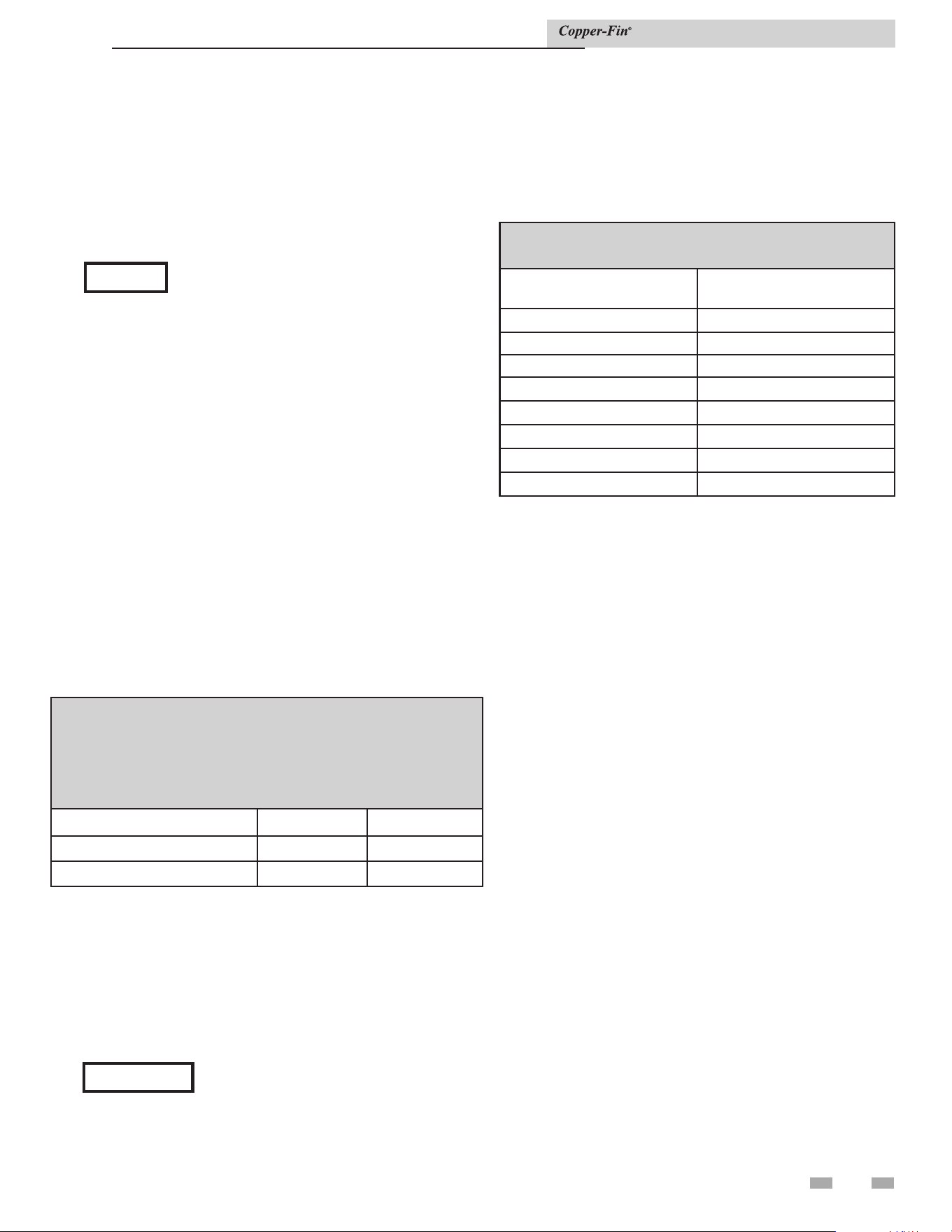
51
7 Domestic water heaters
This section applies only to those units used to supply potable hot water for domestic use. The water heater must be installed with
a storage tank.
This section contains specific instructions for those units used to supply domestic hot water. All warnings, cautions, notes and
instructions in the general installation and service sections apply to these instructions. Water heaters are designed for installation
with a properly sized storage tank. The use of a properly sized pump and the control of water velocity, as explained below, are
important for correct operation of your water heater.
TABLE 7B
Temperature Rise Chart
Model
Temperature
Rise
497 15°F
647 19°F
747 22°F
987 18°F
1257 23°F
1437 26°F
1797 32°F
2067 37°F
Water velocity control
NOTICE
To ensure proper velocity through the
heat exchanger, you must regulate the
temperature rise across the heat exchanger
from inlet to outlet. Do this upon initial
installation and periodically recheck.
The correct temperature rise across the
heat exchanger ensures proper velocity
in the tubes. This will yield long life and
economical operation from your hot water
heater. Excessive lime build up in the
tube is caused by too low velocity through
the tubes. Excessive pitting or erosion in
the tube is caused by too high velocity
through the tubes. Take care to measure
temperature rise and maintain a velocity
as follows:
1. With the pump running and the water heater off,
the inlet and outlet thermometers should read the same
temperatures. If they do not, an adjustment must be
made to your final calculation.
2. Turn the water heater “On” and allow time for the
temperature to stabilize. Record the difference between
the inlet and outlet temperatures. This difference will
be the “temperature rise”.
3. Compare the temperature rise on the heater with the
required temperature rise in Table 7B. Should
adjustment be needed, proceed as follows:
If the temperature rise is too high, the water velocity is too
low. Check the following:
1. Check for restrictions in the outlet of the water heater.
2. Be sure all valves are open between the water heater and
the tank.
3. Check the pump to be sure it is running properly and
that the pump motor is running in the proper direction
(see arrow on volute housing).
4. Be sure the installed circulation pipes between the
water heater and storage tank are not less than 2 1/2'' in
diameter on Models 987 - 2067.
5. Common manifold piping for multiple unit installations
will require larger minimum pipe sizes and tank
circulating tappings to ensure proper flow. See Table
7C on page 56.
If the temperature rise is too low, the water velocity is too
high. Adjust as follows:
1. Slowly throttle the valve on the outlet side of the water
heater until the temperature rise is steady at the required
temperature rise as noted in Table 7A.
2. Sustained high water velocity and low temperature rise
may result in pitting or erosion of the copper tubes in the
heat exchanger. This is a non-warrantable failure.
Temperature rise must be properly adjusted to achieve the
specified flow rate.
Installation & Service Manual
Initial set-up of maximum water flow
On initial start-up, the maximum water flow through the heat
exchanger must be manually set before normal operation
begins.
The heat exchanger is capable of operating within the design
flow rates required for the water heater, storage tank(s), and
connecting piping. Erosion of the finned copper tubes may
occur if the flow rate exceeds the maximum allowable flow rate
through the water heater. The maximum flow rate through the
water heater must be adjusted. Flow rate can be determined by
measuring the temperature rise through the water heater when
it is firing at full rate input.
TABLE - 7A
MAXIMUM WATER FLOW
⚠ CAUTION: The maximum flow rate through a water heater with
a copper heat exchanger must be set to provide and not exceed the
following flow:
Model Maximum Flow
Maximum Flow for
CuNi Heat Exchanger
497, 647, and 747 55 GPM 75 GPM
987, 1257, 1437, 1797, and 2067 90 GPM 115 GPM
NOTICE
When connecting the unit to piping made of
a different material, use of a dielectric fitting
or a dielectric union conforming to ASSE
1079 is recommended to prevent corrosion
and potential subsequent water leaks at or
near the connection. Dielectric fittings may
be required by local plumbing codes.
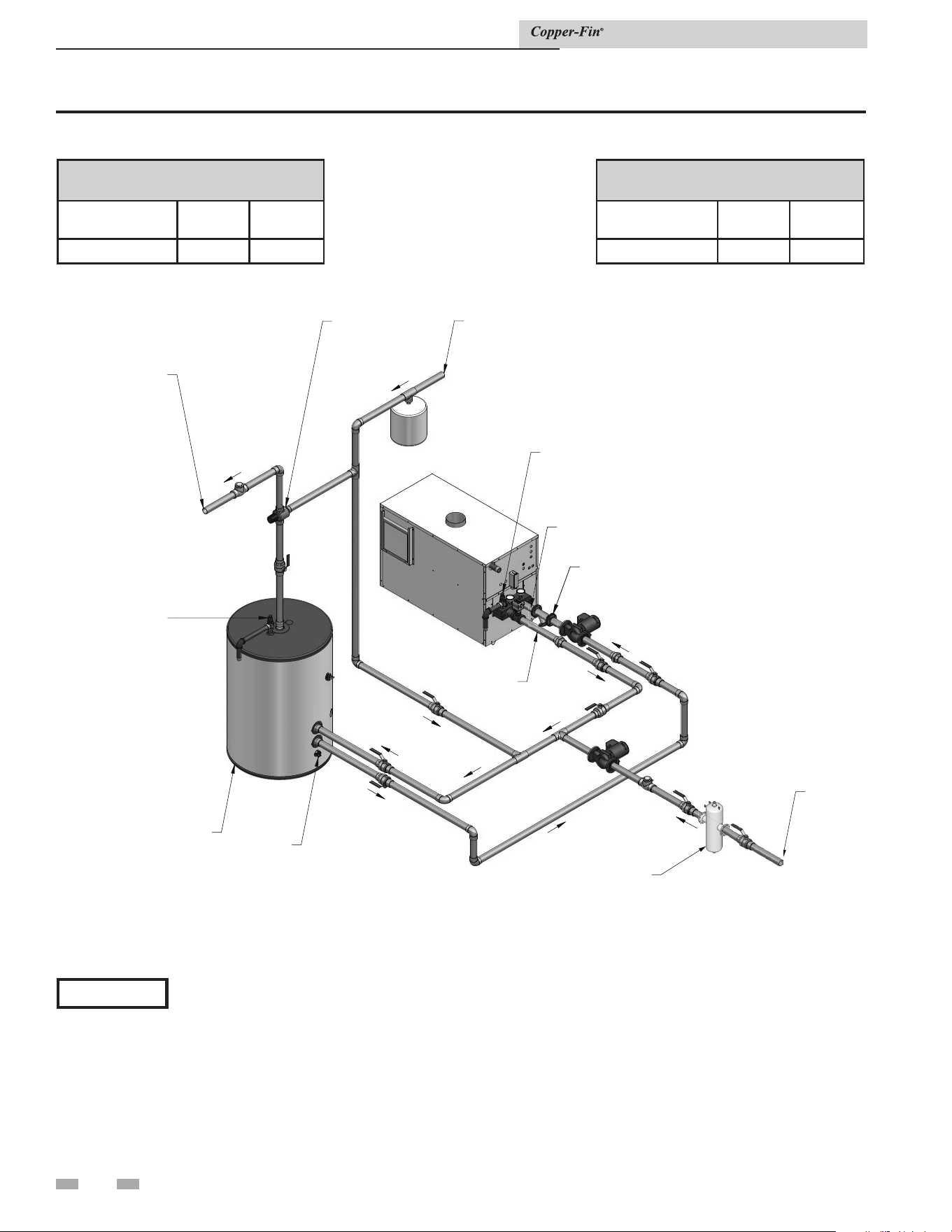
52
7 Domestic water heaters
OUTLET
COLD
WATER
SUPPLY
BUILDING
HOT WATER
SUPPLY
RELIEF
VALVE
LOCK-TEMP
STORAGE
TANK
DRAIN
BUILDING
RETURN
INLET
RELIEF
VALVE
MIXING
VALVE
Y-STRAINER
DIR #2000570589_000
BUILDING RECIRCULATION
FILTER (IF REQUIRED SEE
SECTION 7)
Figure 7-1_Typical water heater piping with storage tank
Installation & Service Manual
COMMON MANIFOLD SIZE (Min.)
Models: 497 - 747
Number of Units GPM
Diameter
(in.)
1 60 2 1/2
COMMON MANIFOLD SIZE (Min.)
Models: 987 - 2067
Number of Units GPM
Diameter
(in.)
1 90 2 1/2
*Please note that these illustrations are meant to show system piping concept only, the installer is responsible
for all equipment and detailing required by local codes.
NOTICE
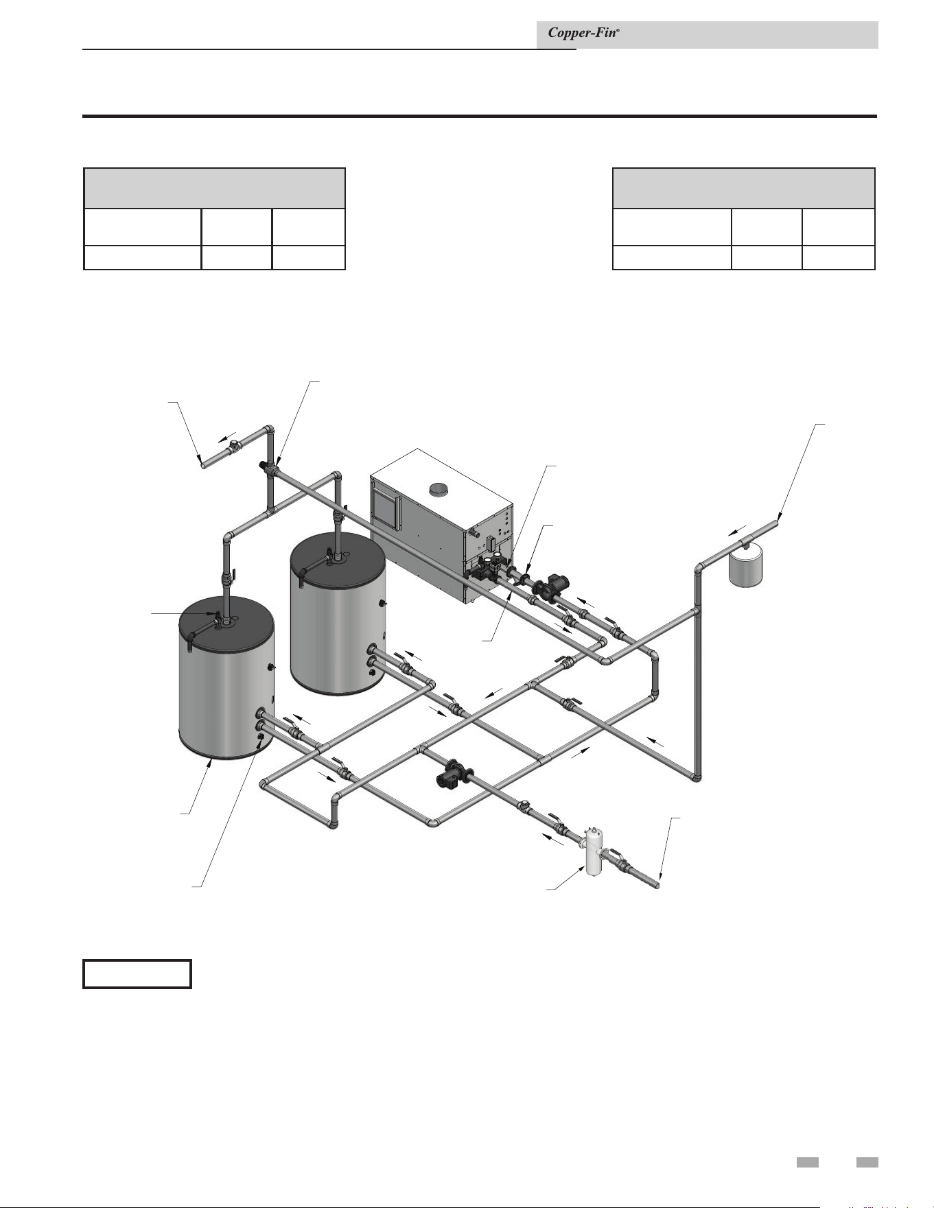
53
OUTLET
COLD
WATER
SUPPLY
BUILDING
HOT WATER
SUPPLY
RELIEF
VALVE
LOCK-TEMP
STORAGE
TANK
DRAIN
INLET
MIXING
VALVE
Y-STRAINER
BUILDING
RETURN
DIR #2000570590_000
BUILDING RECIRCULATION
FILTER (IF REQUIRED SEE
SECTION 7)
Figure 7-2_Single water heater piping with two storage tanks
7 Domestic water heaters (continued)
Installation & Service Manual
COMMON MANIFOLD SIZE (Min.)
Models: 497 - 747
Number of Units GPM
Diameter
(in.)
1 60 2 1/2
COMMON MANIFOLD SIZE (Min.)
Models: 987 - 2067
Number of Units GPM
Diameter
(in.)
1 90 2 1/2
*Please note that these illustrations are meant to show system piping concept only, the installer is responsible
for all equipment and detailing required by local codes.
NOTICE
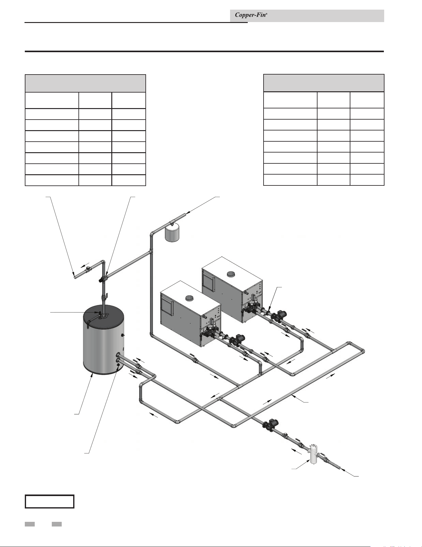
Installation & Service Manual
54
7 Domestic water heaters
RELIEF
VALVE
BUILDING
HOT
WATER
SUPPLY
COLD
WATER
SUPPLY
BUILDING
RETURN
MIXING
VALVE
DRAIN
REFERENCE CHART FOR
COMMON MANIFOLD SIZE
LOCK-TEMP
STORAGE
TANK
Y-STRAINER
(TYPICAL)
DIR #2000570592_000
BUILDING RECIRCULATION
FILTER (IF REQUIRED SEE
SECTION 7)
Figure 7-3_Multiple water heater piping with a single storage tank
COMMON MANIFOLD SIZE (Min.)
Models: 497 - 747
Number of Units GPM
Diameter
(in.)
2 120 3 1/2
3 180 4
4 240 5
5 300 5
6 360 6
7 420 6
8 480 6
COMMON MANIFOLD SIZE (Min.)
Models: 987 - 2067
Number of Units GPM
Diameter
(in.)
2 180 4
3 270 5
4 360 6
5 450 6
6 540 6
7 630 8
8 720 8
*Please note that these illustrations are meant to show system piping concept only, the installer is responsible
for all equipment and detailing required by local codes.
NOTICE
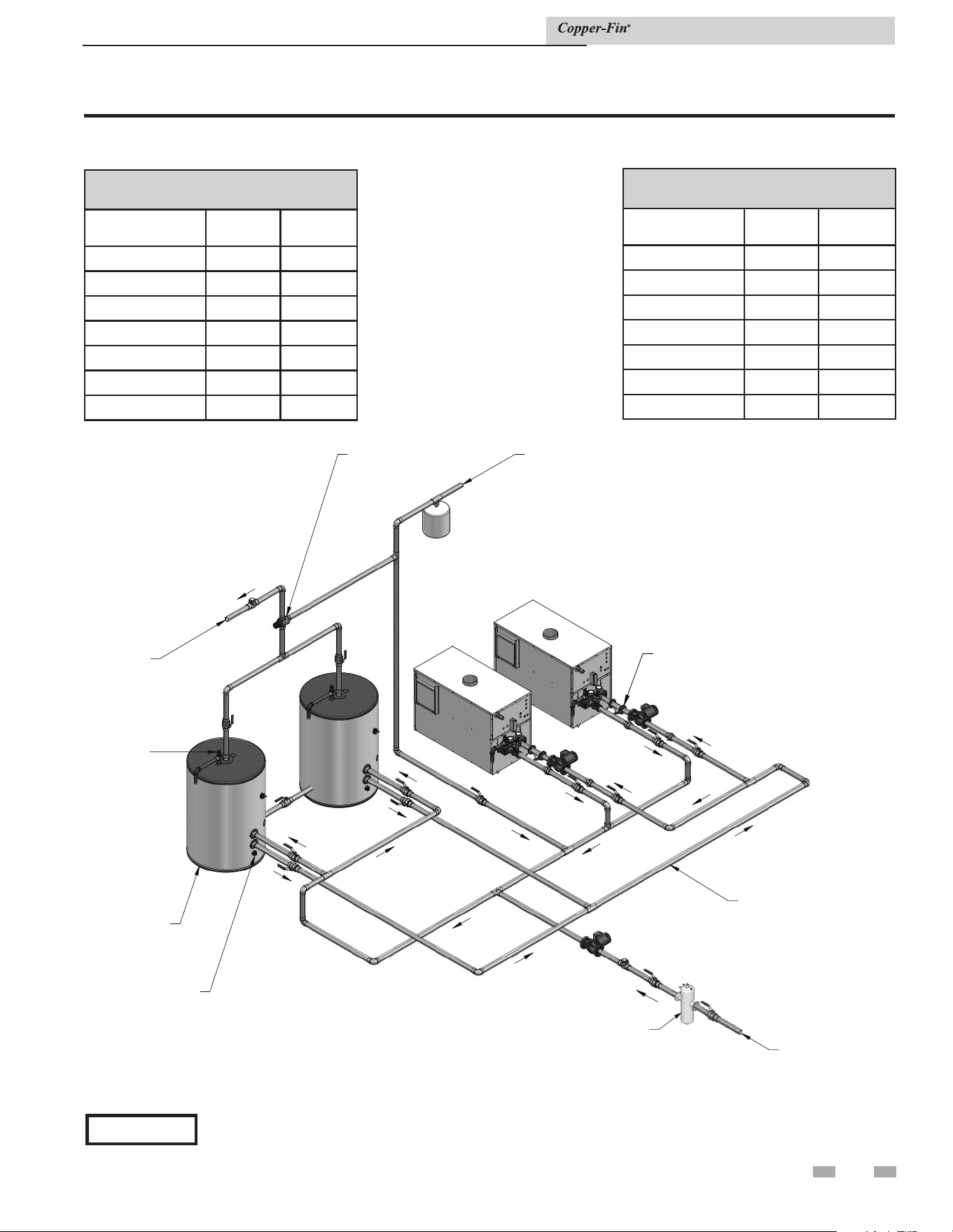
RELIEF
VALVE
BUILDING
HOT
WATER
SUPPLY
COLD
WATER
SUPPLY
BUILDING
RETURN
MIXING
VALVE
DRAIN
REFERENCE CHART FOR
COMMON MA
NIFOLD SIZE
LOCK-TEMP
STORAGE
TANK
Y-STRAINER
(TYPICAL)
DIR #2000570593_000
BUILDING RECIRCULATION
FILTER (IF REQUIRED SEE
SECTION 7)
Figure 7-4_Multiple water heater piping with multiple storage tanks
55
7 Domestic water heaters (continued)
Installation & Service Manual
COMMON MANIFOLD SIZE (Min.)
Models: 497 - 747
Number of Units GPM
Diameter
(in.)
2 120 3 1/2
3 180 4
4 240 5
5 300 5
6 360 6
7 420 6
8 480 6
COMMON MANIFOLD SIZE (Min.)
Models: 987 - 2067
Number of Units GPM
Diameter
(in.)
2 180 4
3 270 5
4 360 6
5 450 6
6 540 6
7 630 8
8 720 8
*Please note that these illustrations are meant to show system piping concept only, the installer is responsible
for all equipment and detailing required by local codes.
NOTICE
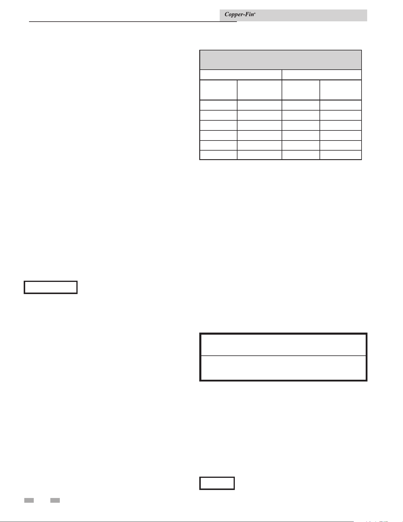
7 Domestic water heaters
TABLE 7C
Pipe Sizing Chart
497 - 747 987 - 2067
Number of
Units
Common Pipe
Size (Min.)
Number of
Units
Common Pipe
Size (Min.)
1 2'' 1 2 1/2''
2 3'' 2 4''
3 3'' 3 4''
4 4'' 4 5''
5 5'' 5 6''
6 5'' 6 6''
Water chemistry
The required temperature rise and the standard pump sizing
are based on the heating of potable water with a hardness
of 5 to 20 grains per gallon and a total dissolved solids not
exceeding 350 ppm. Consult the appliance manufacturer when
heating potable water exceeding these specifications.
Heating of high hardness and/or high total dissolved solids
water will require a larger circulating pump, an optional
cupro-nickel heat exchanger and a revised temperature rise
specification based on the water chemistry of the water to be
heated.
Water with a hardness of less than 5 grains per gallon will
usually have a low pH which can be aggressive and corrosive
causing non-warrantable damage to the heater, pump and
associated piping. Corrosion due to water chemistry generally
shows up first in the hot water system because heated water
increases the rate of corrosive chemical reactions.
Pipe size requirements
Table 7B, pipe sizing chart provides the minimum pipe size for
common manifold piping to ensure adequate flow.
Required temperature rise
Based on heating potable water with a hardness of 5 to 20
grains per gallon and/or total dissolved solids not exceeding
350 ppm, see Water Chemistry, this page.
Installation & Service Manual
Circulating pump
1. The water heater must be connected to a properly sized
pump that circulates water between the heater and
storage tank.
2. The pump is sized to heater input and water hardness.
Care should be taken to size the pump correctly. See
Water Chemistry, this page.
3. The water heater is equipped with a factory-supplied
pump delay system in accordance with the requirements
of the latest edition of ASHRAE 90.1.
4. Lubricate the pump to the manufacturer’s
recommendations. Pump damage due to inadequate
lubrication is non-warrantable.
5. Standard water heaters are furnished with the following
circulating pump. Mount the pump on the unit’s inlet
water connection.
Models 497 - 747
1/4 HP, 120 VAC, 5.8 Amps
Models 987 - 2067
1/2 HP, 120 VAC, 7.4 Amps
This pump is sized based on installation of a single storage
tank and heater in close proximity. If the number of fittings
and straight pipe exceeds the quantities shown in this section, a
larger pump will be required.
The standard pump selection is based on the following pipe and
fittings from the unit to the storage tank:
• 6 90° elbows
• 2 unions
• No more than 45
feet of straight pipe.
• 2 ball valves
• 1 cold water tee
NOTICE
For every elbow and tee in excess of those shown
above, deduct 5 feet from maximum allowable
straight pipe in heater to tank circulating loop.
56
NOTICE
1. Do not use the appliance to directly
heat swimming pool or spa water.
2. At initial fill and during water heater
start-up and testing, check system
thoroughly for any leaks. Repair all leaks
before proceeding further.
3. When water hardness levels are less
than 5 gpg or 85.5 mg/l, the following is
recommended:
a. Flush and clean existing water heating
system prior to installation.
b. Inspect and, if necessary, replace the
anodes in any existing tanks.
c. Install a Y-strainer on the inlet of each
water heater as detailed in this section.
d. Limit the run time of the hot water
recirculation loop.
e. Filter the hot water recirculation loop
to a level of 10 microns. CAUTION:
Check recirculation pump size to verify
it is sized for filter addition and upsize if
necessary.
4. When water softener is required, a
Template Assisted Crystallization system
is recommended.
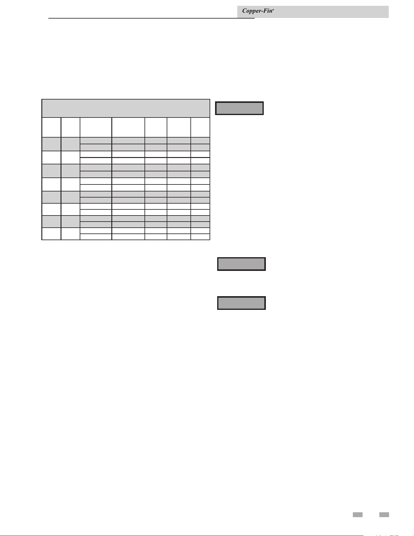
57
Minimum pump performance
This is based on heating potable water with a hardness of
5 to 25 grains per gallon and/or total dissolved solids not
exceeding 350 ppm. See Water Chemistry, page 56.
Heat exchanger
On all models, header inspection plugs can be removed for
field inspection and cleaning of copper tubes. The entire
heat exchanger may be easily removed from the unit.
Potable hot water temperature
control settings
Domestic water temperature
You must take adequate care to prevent
scald injury when storing water at elevated
temperatures for domestic use.
⚠ WARNING
This unit has an adjustable temperature control to maintain the
desired water temperature set point. See Setting Temperature
Control, page 41, for instructions to adjust the temperature
control. The temperature control is factory preset at
approximately 125°F (52°C) or less. Households with small
children or invalids may require 120°F (49°C) or lower
temperature hot water to reduce risk of scald injury.
Operate this high efficiency hot water heater at a temperature
setting high enough to prevent condensing of the products of
combustion on the unit’s heat exchanger or in the attached
venting system. A water temperature setting that is above the
dew point of the gas combustion products should prevent
condensate formation
To guard against scald injury, you must use a
properly sized thermostatic mixing valve to
supply domestic hot water at temperatures
less than 125°F (52°C).
⚠ WARNING
Return water temperatures must not be less
than 140°F (60°C). If lower return water
temperatures are required, follow the
instructions for Low Temperature Return
Water Systems, page 32.
⚠ WARNING
Installation & Service Manual
7 Domestic water heaters (continued)
TABLE 7D
Water Heater Pump Applications
Model
Pipe
Size
Water
Hardness
Grundfos
Pump
Flow
Rate
(GPM)
Head
Loss
(FT)
Temp.
Rise
497
2"
5 to 15 gpg TP44PAB 55 10 15°F
15 to 20 gpg UP 43-110 SF 75 10 11°F
647 2"
5 to 15 gpg TP44PAB 55 10 19°F
15 to 20 gpg UP 43-110 SF 75 10 14°F
747 2"
5 to 15 gpg TP44PAB 55 10 22°F
15 to 20 gpg UP 43-110 SF 75 10 16°F
987 2-1/2"
5 to 15 gpg TP24PAB 90 15 18°F
15 to 20 gpg TP 50-160/2B 115 15 14°F
1257 2-1/2"
5 to 15 gpg TP24PAB 90 15 23°F
15 to 20 gpg TP 50-160/2B 115 15 18°F
1437
2-1/2"
5 to 15 gpg TP24PAB 90 15 26°F
15 to 20 gpg TP 50-160/2B 115 15 21°F
1797
2-1/2"
5 to 15 gpg TP24PAB 90 15 32°F
15 to 20 gpg TP 50-160/2B 115 15 26°F
2067
2-1/2"
5 to 15 gpg TP24PAB 90 15 37°F
15 to 20 gpg TP 50-160/2B 115 15 30°F
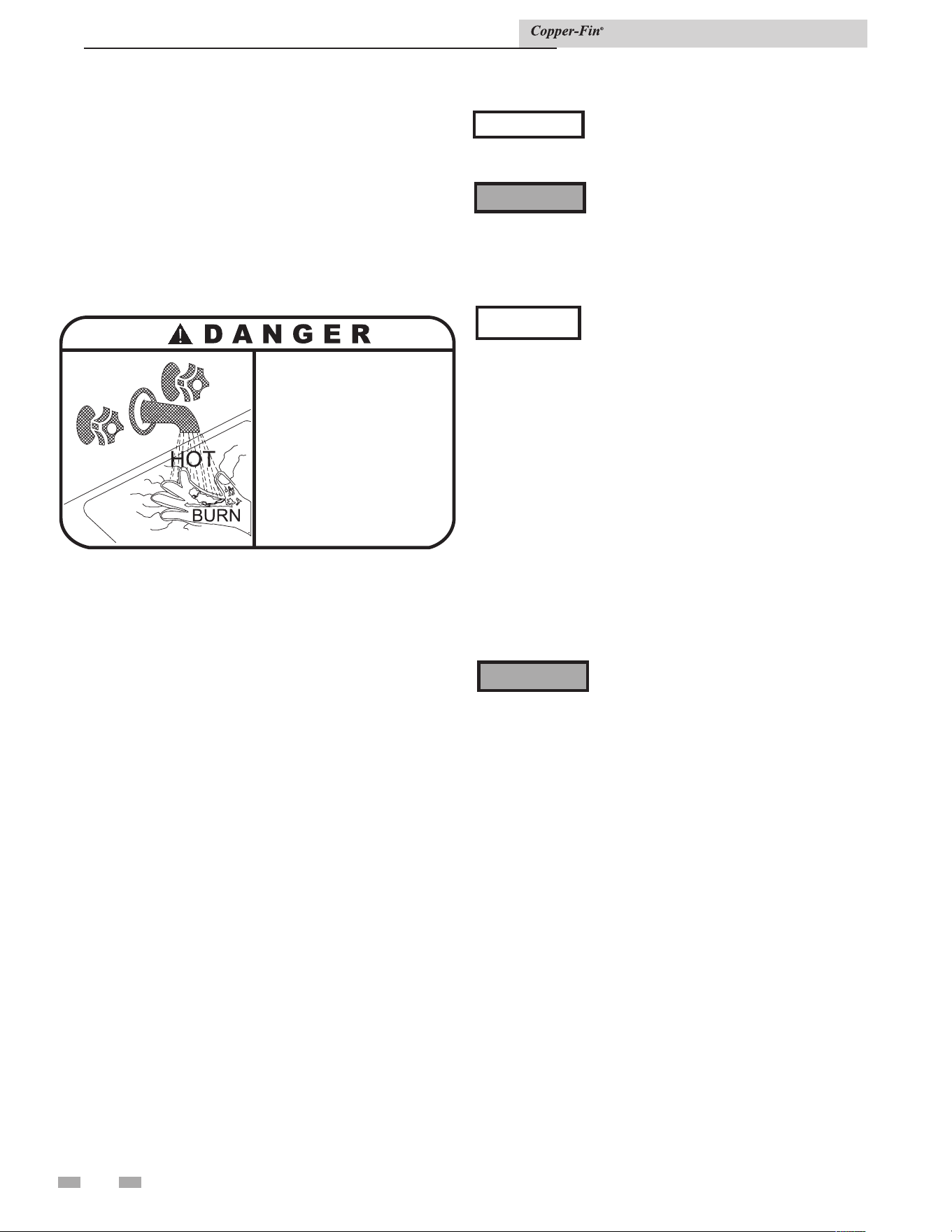
7 Domestic water heaters
Storing the water at a higher temperature and thermostatically
mixing the water increases the available quantity of mixed hot
water, greatly reducing the possibility of condensate forming
on the heat exchanger or in the venting system and helps
prevent water born bacteria growth.
Some states may require a lower water temperature setting for
specific applications. Check local codes or your gas supplier for
domestic hot water temperature requirements.
Remember, no water heating system provides exact temperatures
at all times. Let the system operate a few days at your desired
settings to determine correct settings for your needs.
1. These units are equipped with an operating temperature
control.
2. The control set points are preset to a low test setting when
shipped from the factory.
3. Reset the temperature set points to the lowest settings which
will satisfy hot water demands, eliminate a possible
condensate problem and prevent a risk of scald injury.
4. The High-Fire Offset should normally be adjusted to “0”
when supplying potable hot water for domestic use.
5. Stage firing can be achieved by adjusting the High-Fire
Offset to any value other than zero. Typically, a setting of
3°F is 5°F is suitable for stage firing in a water heater
application. Stage firing of a potable water heater is
normally only used to replace system standby heat loss.
6. All stages of burner operation should fire when there is a
major draw from the potable hot water storage system.
This prevents possible condensate problems and ensures a
rapid recovery of the hot water used.
The High-Fire stage will be delayed by
approximately 10 seconds to allow a
soft start of the water heater.
When water is stored at temperatures
above 125°F (52°C), a thermostatic
mixing valve must be installed on the
hot water outlet from the storage tank
to supply lower temperature water and
prevent the risk of a scald injury.
⚠ WARNING
This water heater, when set at a lower
temperature setting, is not capable
of producing hot water of sufficient
temperature for sanitizing purposes.
• Water temperature over 125°F (52°C)
can cause severe burns instantly or
death from scalds.
• Children, disabled and elderly are
at highest risk of being scalded.
• See instruction manual before
setting temperature at heating
appliance.
• Feel water before bathing or showering.
• If this appliance is used to produce
water that could scald if too hot,
such as domestic hot water use,
adjust the outlet control (limit) or use
temperature limiting valves to obtain
a maximum water temperature of
125°F (52°C).
Location of cold water supply piping
connections
Incorrect piping of the cold water supply to the system
may result in excessive low temperature operation
causing condensate formation on the heat exchanger and
operational problems. You must install the cold water
supply piping in the discharge piping from the heater to
the storage tank. This allows the cold water to be tempered
in the storage tank before entering the heater. See FIG.
7-1, on page 52, and typical installation drawings provided
with the unit for correct piping. Higher water temperatures
reduce condensate formation.
Should overheating occur or the gas
supply fail to shut off, do not turn off
or disconnect the electrical supply to
the pump. Instead, shut off the gas
supply at a location external to the
unit.
⚠ WARNING
Installation & Service Manual
NOTICE
NOTICE
58

59
7 Domestic water heaters (continued)
High water temperature limit control
The unit is equipped with an adjustable setting, auto-reset
high water temperature limit control. The hot water heater
temperature limit control has a maximum limit setting of
200°F (93°C). If water temperature exceeds the set point,
the limit will break the control circuit and shut down the
unit. The limit control will only be reset after the water
temperature has cooled below the set point of the limit.
The high water temperature limit control is mounted in
the outlet side of the front header. A manual reset high
water temperature limit control is available as an optional
control.
Optional relief valve
This water heater is normally supplied with a temperature
and pressure relief valve(s) sized in accordance with
applicable codes. Units may be supplied with an optional
pressure only relief valve(s). When a water heater equipped
with this optional relief valve is piped to a separate storage
vessel, the storage vessel MUST have a properly installed
temperature and pressure relief valve which complies with
local codes.
Thermal expansion
A relief valve which discharges periodically may be due
to thermal expansion in a closed system. A hot water
supply boiler installed in a closed system, such as one with
a backflow preventer or check valve installed in the cold
water supply, shall be provided with means to control
expansion. Contact the water supplier or local plumbing
inspector on how to correct this situation. Do not plug or
cap the relief valve discharge!
Cathodic protection
Hydrogen gas, which is extremely flammable, can be
produced in a hot water system that has been unused for
a long period of time (generally two weeks or more). To
prevent the possibility of injury under these conditions,
open the kitchen sink hot water faucet for several minutes
before using any electrical appliance connected to the
hot water system. If hydrogen is present, there will be an
unusual sound such as air escaping through the pipe as the
hot water begins to flow. Do not smoke or have open flames
near the faucet at this time.
Installation & Service Manual
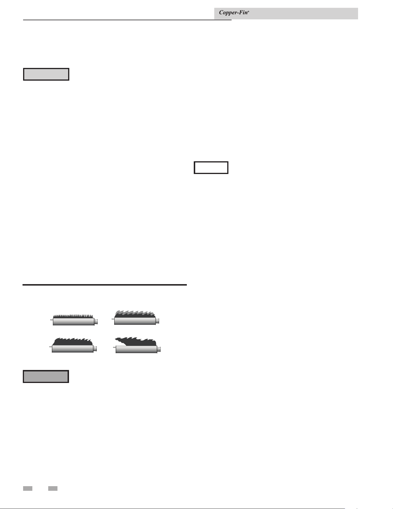
60
8 Maintenance
Listed below are items that must be checked to ensure safe,
reliable operations. Verify proper installation after servicing.
Label all wires prior to disconnection when
servicing controls. Wiring errors can cause
improper and dangerous operation.
⚠ CAUTION
Appliance area
Keep appliance area clear and free from combustible materials,
gasoline and other flammable vapors and liquids.
Water circulating pump
Inspect pump every six months and oil as necessary. Use SAE 30
non-detergent oil or lubricant specified by pump manufacturer.
Burner flames
Visually check main burner flames at each start up after long
shutdown periods or at least every six months. Burner viewports
are located on the right and left sides of the unit.
Check fill water meter
Check fill water meter for water usage. If the amount exceeds
5% of your system volume, you could have a leak. Have
the system checked for leaks and fixed by a qualified service
technician.
Test boiler water
Test boiler water. Reference the Copper-Fin Installation and
Operation Manual for guidelines. When test indicates, clean
system water with approved system restorer following the
manufacturer's information.
NORMAL
A
YELLOW TIP
B
D
FLAME LIFT
C
YELLOW FLAME
WARNING: The area around the burners is hot and direct contact could result in burns!
Figure 8-1_Flame patterns
The areas around the burner viewports
are hot. Direct contact with the unit could
result in burns.
⚠ WARNING
Normal Flame: A normal flame is blue with slight yellow tips,
has a well-defined inner cone, and displays no lifting flames.
Yellow Tips: The usual causes for yellow tips on the burner
flame are burner air flow blockage or partial obstruction.
Yellow Flames: The usual causes for yellow flames are primary
air flow blockage to the burner(s) or excessive gas input. Correct
this condition immediately.
Flue gas passageways cleaning procedure
Any sign of soot around the outer jacket, at the burners or in the
areas between the fins on the copper heat exchanger indicates
a need for cleaning. The following cleaning procedures must
only be performed by a qualified serviceman or installer. Proper
service is required to maintain safe operation. Properly installed
and adjusted units seldom need flue cleaning.
NOTICE
All gaskets on disassembled components must
be replaced with new gaskets on reassembly.
Gasket kits are available from your distributor.
Burner removal and cleaning
1. Turn off main power to unit.
2. Turn off main manual gas shutoff to unit.
3. Remove the front outer jacket panels.
4. Disconnect manifold from gas train using union(s) just
below each gas valve(s).
5. Remove mounting screws from manifold mounting
brackets. Pull the manifold/orifice assembly away from
burners. Repeat for each manifold assembly.
6. Remove two mounting screws from burner and slide
burner out toward front of unit. Use caution to prevent
damage to burners, refractory, hot surface igniter or wiring.
7. Remove soot from burners with a stiff bristle brush.
Dirt may be removed from burner ports by rinsing the
burner thoroughly with water. Drain and dry burners
before re-installing. Damaged burners must be replaced.
When installed in a dusty and dirty location, the burners may
require cleaning on a 3 to 6 month schedule or as needed,
based on severity of contamination. Contaminants can be
drawn in with the combustion air. Non combustible particulate
matter such as dust, dirt, concrete dust or dry wall dust can
block burner ports and cause non-warrantable failure. The
standard inlet air filter will help eliminate dust and dirt from
entering the unit. Use extreme care when operating a unit for
temporary heat during new construction. The burners could
require a thorough cleaning before the unit is placed in service.
Installation & Service Manual
Lifting Flames: The usual causes for lifting flames are over
firing the burner(s), excessive primary air, or high draft.
If you observe improper flame patterns, examine the venting
system, ensure proper gas supply, and ensure adequate supply
of combustion and ventilation air.

61
8 Maintenance (continued)
Heat exchanger cleaning
1. While burners are removed, check the heat exchanger
surface for sooting. If present, heat exchanger must be
cleaned and problem corrected. Proceed as follows.
2. Remove gas manifold(s)/orifice assemblies as described
in steps 1 through 5 in Burner Removal and Cleaning,
page 60.
3. Disconnect wiring from the hot surface igniter and
hose from the burner pressure tap.
4. Remove inner jacket panel mounting screws and slide
door assembly out toward front of the unit. Use
caution to prevent damage to the refractory and hot
surface igniter.
5. Check “V” baffles and frame runners along front
and back edges of heat exchanger. Remove and clean if
necessary.
6. Remove soot from heat exchanger with a stiff bristle
brush. Use a vacuum to remove loose soot from
surfaces and inner chamber.
7. The heat exchanger can be removed by sliding towards
the front of the unit. Once the heat exchanger is
removed from the unit, a garden hose can be used
to wash the tubes to ensure that all soot is removed
from the heat exchanger surfaces. Note: Do not wet the
unit’s refractory.
8. Ensure that all burner ports are cleaned to remove any
soot. See Burner Removal and Cleaning, page 60.
9. Carefully reinstall the heat exchanger, “V” baffles, and
frame runners if removed from the unit. Note: Make
sure frame runners seal securely where they contact the
front and rear compartment refractory.
10. Carefully reinstall inner jacket panels, burners,
manifolds, wires and hoses. Use new gasket material to
ensure a proper air seal.
11. Reassemble all gas and water piping. Test for gas leaks.
12. Reassemble outer jacket panels.
13. Cycle unit and check for proper operation.
Electrical
This unit uses a transformer to supply a low voltage control
circuit. The voltage on the secondary side should be 24 to
28VAC when measured with a volt meter. Larger models
have a 7AMP circuit breaker provided on the secondary
side of the transformer. A tripped circuit breaker indicates
a short in the 24VAC controls that must be corrected.
Combustion and ventilation air
Combustion air filter
See Combustion Air Filter, page 13.
Air flow
Check frequently to be sure the flow of combustion and
ventilation air to the unit is not obstructed.
Combustion air fan
These units use a fan-assisted combustion process. These units
have one fan to supply combustion air to the burners.
Fan cleaning
Check combustion air fan every six months. Clean fan as
required only when installed in a dusty or dirty location. Oiling
is not required.
Combustion air fan adjustment
The combustion air fan is factory preset and should not need
adjustment in most cases. Follow the steps below to adjust the
fan if a continuous Low Air Status Code occurs.
Check for proper installation and draft in the venting system.
Correct as required.
Adjusting air pressure
The following is a recommended method for setting the air
pressure for the fan.
Setup procedure
To the left of the fan is an air pressure switch with a large and
small tube delivering pressure from points inside the unit
(see FIG. 8-2). The pressure in the large tube is the chamber
pressure. By disconnecting the cap from the tee in the hose and
connecting it to the "(+)" side of a manometer, you can read the
air chamber pressure.
Upon a call for heat, the fan will run for about 90 seconds
before going into soft lockout. If necessary, turn the power to
the unit OFF and then back ON again to recycle the fan.
Note: If the unit has been firing recently, allow the unit to
cool for five minutes with the fan running before
beginning the adjustment procedure.
Note: Retain the plastic cap removed from the tee for
reinstallation when complete.
Installation & Service Manual
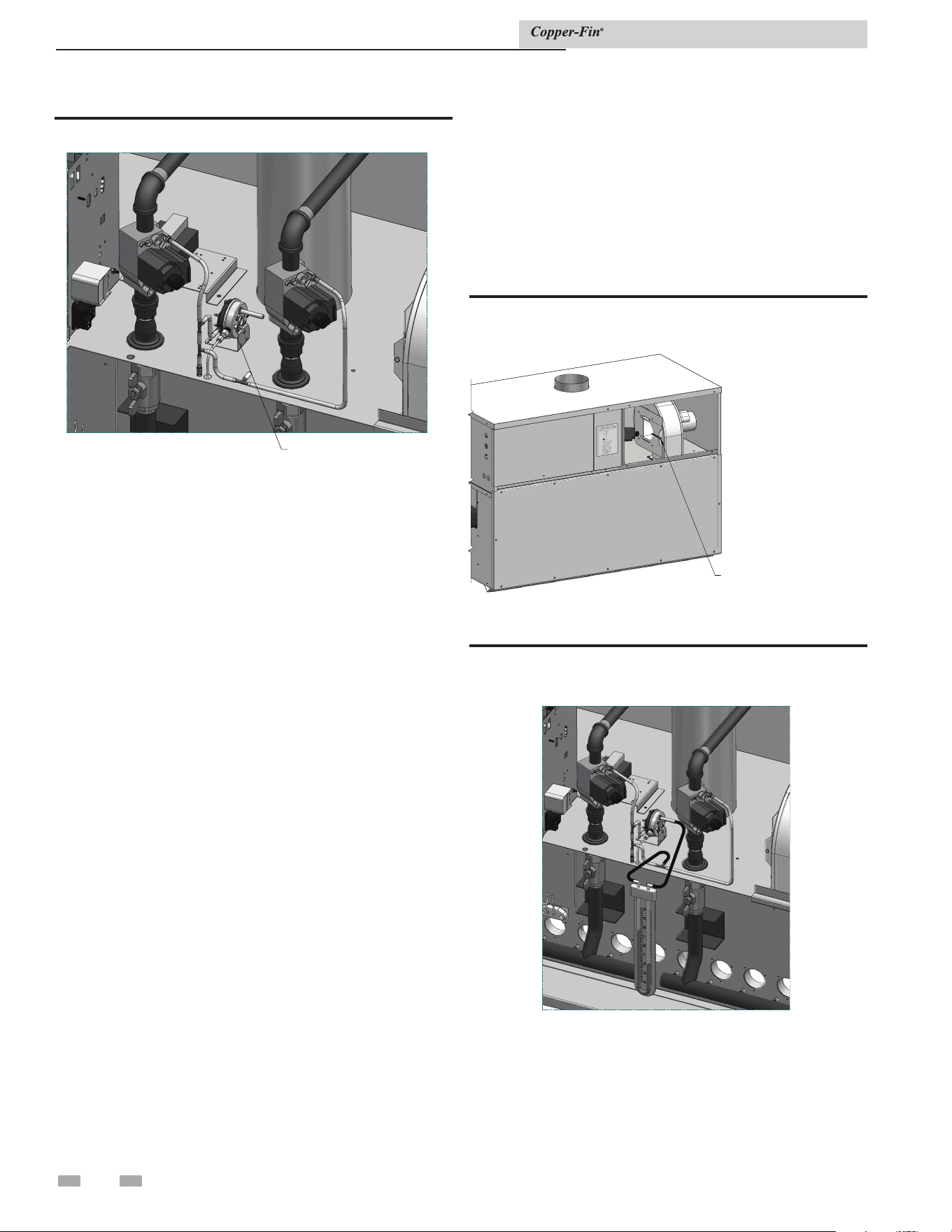
62
8 Maintenance
AIR PRESSURE SWITCH
Figure 8-2_Air pressure switch
Adjustment procedure Models 497 - 1257:
1. Remove the upper front jacket panels from the unit to
access the upper chamber.
2. Locate the air shutter on the side of the fan housing
(see FIG. 8-3). Turn the adjustment screw on the air
shutter to open or close the shutter. Increase air shutter
opening to increase air pressure. Decrease air shutter
opening to decrease air pressure.
3. Adjust the air shutter until the air chamber pressure is
nominally 1.25 - 1.30 inches water column for Models
497 - 747 and 1.35 - 1.45 inches water column for Models
987 - 1257. See FIG. 8-4 on installations up to 2000 feet
altitude. Contact the factory for high altitude pressure
settings.
4. Once the adjustment procedure is complete, reconnect
the cap to the tee in the hose and check all tubing and wire
connections for a snug fit. Test fire the unit. Reinstall upper
panels.
Adjustment procedure: Models 1437, 1797 and 2067
1. Remove the upper front jacket panels from the unit to
access the upper chamber.
2. Slightly loosen the screws that attach the fan transition box
to the metal base (see FIG. 8-5).
3. Locate the air shutter at the rear of the fan duct (see
FIG. 8-6). Move the air shutter towards the rear of the
unit to increase air pressure. Move the air shutter towards
the front of the unit to decrease air pressure.
4. Adjust the air shutter until the air chamber pressure is
nominally 1.35 - 1.45 inches water column. See FIG. 8-4
for installations up to 2000 feet altitude. Contact the
factory for high altitude settings.
5. Once the adjustment procedure is complete, reattach the
cap to the tee in the hose and check all tubing and wire
connections for a snug fit. Test fire the unit. Reinstall upper
panels.
TURN THE ADJUSTMENT
SCREW ON THE AIR
SHUTTER TO OPEN OR
CLOSE THE SHUTTER
Figure 8-3_Adjusting air shutter
Figure 8-4_Combustion air adjustment with manometer
to set differential pressures
Installation & Service Manual
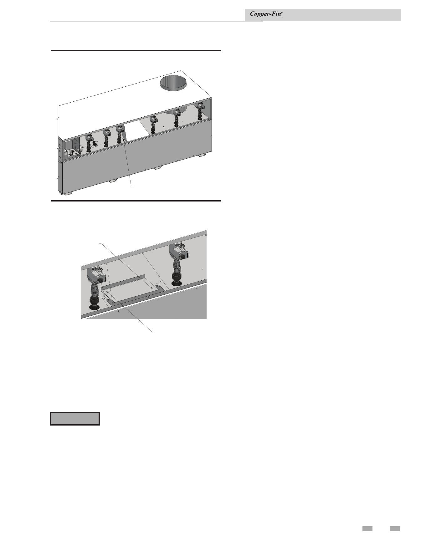
63
8 Maintenance (continued)
TRANSITION BOX SCREWS
Figure 8-5_Loosening the transition box screws,
Models 1437, 1797 and 2067 only
INCREASE AIR
PRESSURE
DECREASE
A
IR PRESSURE
Figure 8-6_Adjusting the air shutter
Servicing a hot surface igniter and
ignition module
This unit uses a proven hot surface ignition module and a
hot surface igniter. The hot surface ignition module is not
repairable. Any modification or repairs will invalidate the
warranty.
Do not attempt to repair a faulty hot
surface igniter or ignition module. Any
modification or repairs may create
hazardous conditions that result in
property damage, personal injury, fire,
explosion and/or toxic gases.
⚠ WARNING
A faulty hot surface igniter or ignition module must be
replaced with an identical part. A specification igniter
and ignition module for this specific unit is available from
your local distributor. Do not use general purpose field
replacement ignition modules or igniters.
Sequence of operation
Overview
This sequence of operation can be considered the order of
events in sequential order that occur after the appliance has
received a call for heat. The process begins with 120VAC
power entering the appliance and ends with the appliance
going into an idle state after completion of a successful call
for heat.
Ignition system checkout
1. Turn off gas supply to unit.
2. Turn electric power on.
3. Adjust the set point on the temperature control to a
setting above water temperature or to the highest safe
setting.
4. The igniter will cycle on trial for ignition.
5. The ignition module will lock out and turn the alarm
light on.
6. Adjust the Set Point Differential and High-Fire Offset to
the desired settings.
7. Turn on gas supply.
8. Press the module reset button to reset the ignition
module. This is a red button beside the ignition module
or on the diagnostic panel on the header-end of the unit.
9. If ignition system fails to operate properly, repair work
must be performed by a qualified service person or
installer.
Note: The following descriptions do not include
remotely connected devices that may be
connected to the appliance. Refer to the wiring
diagram for actual point to point wiring
connections that show power delivery.
Installation & Service Manual
1. The POWER switch is placed in the “ON” position.
2. 120VAC power is supplied to the control transformer along
with L1 and F1 on the ignition module.
3. 24VAC is supplied to the electronic temperature control,
the ignition module and the adjustable high limit control.
4. 24VAC is then supplied to the auxiliary limit control
(if equipped).
5. If equipped, 24VAC is supplied to a low water cut-off and
then to the high and low gas pressure switches.
6. 24VAC is supplied to the continuous alarm terminals A1
and A2 and then to the remote stage one terminal strip,
1C and 1NO.
7. 24VAC is supplied to the electronic temperature control.
8. The electronic temperature control then calls for heat.

8 Maintenance
9. 24VAC is supplied to the intermittent alarm field safety
contacts, B1 and B2.
10. 24VAC is supplied to the water flow switch.
11. 24VAC is supplied to the TH terminals on the ignition
module.
12. As power is applied to the TH terminals on the ignition
module, 120VAC is switched from the F2 terminal to start
the combustion air fan at full speed on Models 497 - 747
and at low speed on Models 987 - 2067.
13. 24VAC is supplied to the C terminal of the air pressure
switch. As the low air switch makes, power is supplied to
the ignition module.
14. 24VAC is then supplied to the PS terminals on the ignition
module as the air pressure switch makes to prove fan
operation.
15. The combustion air fan operates for the pre-purge period.
16. At the end of the pre-purge, 120VAC is applied to the hot
surface igniter and the trial for ignition light.
17. The hot surface igniter proves 1800°F (982°C) ignition
temperature by current draw through the ignition module.
18. The ignition module supplies voltage to the MV terminals
on to the gas valve(s).
19. The first stage gas valve(s) opens and supplies gas to the
orifice and burner inlet to pre-mix.
20. The gas/air mixture is forced into the burner and out of the
burner ports under pressure.
21. The hot surface igniter lights the gas/air mixture and
then serves as a flame sensor to prove main burner flame by
rectification.
22. Burners are now firing for approximately 50% of the
heater’s input.
23. 24VAC is supplied from the second stage of the electronic
temperature control across the 2C and 2NO terminals on
the terminal strip on to a control to a relay.
24. The control relay switches the fan on Models 987 -
2067 to high speed and energizes the gas valves for the
remaining 50% of burner input.
25. The remaining gas valves open and supply gas to the
orifice inlet to pre-mix.
26. The gas/air mixture is forced out of the burner ports
and light by carryover from the burners currently
firing.
27. The heater is now firing at full rated input.
Installation & Service Manual
Heat transfer process
28. Heated products of combustion pass over the heat
exchanger transferring heat to the water.
29. The rate of flue product movement is controlled
by “V” baffles on the heat exchanger to maximize heat
transfer.
30. Flue products pass into the flue collector and are
exhausted from the unit.
End of sequence
31. Set point for the high fire on the electronic temperature
control is satisfied.
32. Power to all valves is turned OFF on F9 systems and
power to the high fire gas valves is turned OFF on M9
systems.
33. The water temperature continues to rise and the set
point for low fire is satisfied (M9).
34. Power to the low fire gas valves is turned OFF (M9).
35. The combustion air fan runs for a post purge period and
turns OFF.
36. The appliance is now in a Standby Mode waiting for
the next “call for heat”.
64
65
8 Maintenance
Installation & Service Manual
Maintenance and annual startup
Service technician
(see the following pages for instructions)
General:
• Address reported problems
• Inspect interior; clean and vacuum if
necessary;
• Check for leaks (water, gas, flue,
condensate)
• Examine venting system
• Check system water pressure/system
piping/expansion tank
• Check fill water meter
• Test boiler water. When test indicates,
clean system water with approved system
restorer following manufacturer’s
information.
• Check control settings
• Check ignitor
• Check wiring and connections
• Check flue gas passageways
• Flame inspection (stable, uniform)
• Inspect and clean the burner
• Check manifold gas pressure
• Perform start-up checkout and
performance verification per Section 6 in
the Copper-fin Installation and Operation
Manual.
If combustion or performance
indicate need:
• Clean heat exchanger with a stiff bristle
brush
• Remove and clean burners using
water. Dry before re-assembling.
• Clean the blower wheel with a brush and
vacuum. Do not let dirt from cleaning get
pulled into the blower.
ANNUAL START-UP
Owner maintenance
(see the Copper-fin User’s Information Manual for
instructions)
Daily
• Check appliance area
• Check pressure/temperature
gauge
Monthly
• Check vent piping
• Check air piping
• Check relief valve
• Check building recirculation filter
(if filter required)
• Replace combustion air filter
Note: More frequent replacement may
be necessary in dirty environments.
Periodically
• Test low water cutoff (if used)
• Reset button (low water cutoff)
Every
6 months
• Check appliance piping (gas and
water) for leaks
• Operate relief valve
End
of season
months
• Shut appliance down (unless
boiler used for domestic hot
water)
Table 8A_Service and Maintenance Schedules

66
9 Glossary
Power Supply
(AC120VAC/60Hz)
120VAC/60Hz/1PH power connects to black (line) and white
(neutral) wires located within an electrical wiring box located
on the left side of the unit. A green chassis grounding wire is
also provided for connection to earth ground.
ON/OFF Rocker Switch
The black line voltage wire runs directly to a single pole, single
throw On/Off rocker switch located behind the front cover
accessible by a thumb screw. Turning ON the rocker switch
delivers line voltage to the low voltage transformer and ignition
module.
Note: The On/Off switch does not provide for disconnection
of power being supplied to any remotely connected
devices that may be connected to the unit (i.e. pumps,
louvers, power venters, etc.,). As such, it may be
necessary to locate and turn off power to these items
before attempting to service the unit.
Low Voltage Supply Transformer
A 120VAC to 24VAC transformer located within the control
panel provides 24VAC/60Hz to many of the components located
on the unit. One of its 24VAC outputs (blue) is connected to a
circuit breaker and the other (yellow) is connected to chassis
ground.
24VAC Circuit Breaker
A circuit breaker is provided on Models 987 - 2067 for protection
of the low voltage supply transformer from overloads and short
circuits. The breaker is located inside the unit on the lower right
corner of the control panel. Power from this breaker goes to the
electronic temperature controller, ignition module and various
other components and/or options on the unit. When tripped,
all factory-installed 24VAC components will lose their 24VAC
power.
Manual Reset High-Limit Thermostat
A manual reset high limit thermostat is provided as backup for
the temperature controller. This will be an adjustable dial bulb-
capillary style thermostat that will trip and require resetting
should water temperature exceed its settings. When tripped, all
controls remain powered, but 24VAC is prevented from being
delivered to the ignition module’s thermostat input.
EMS/Sequencer/Remote Aquastat Terminals
The EMS/sequencer/remote aquastat terminals are provided
for connection of the unit to an external energy management
system or sequencer and are located along the top edge of
the terminal strip located within the electrical wiring box.
In addition to providing a means to externally stage fire the
unit, these terminals also provide for remote shutdown and
override by routing through dry contacts from external devices.
Connection of the external dry contacts to these terminals
requires the removal of one or more factory installed jumpers
located on the terminal strip.
Safety Device Terminals
The safety device terminals ensure that no power can be
delivered to the ignition module unless factory/field-installed
safety devices such as flow switches and gas pressure switches
are closed. These safety device terminals are located below the
EMS/Sequencer/Remote Aquastat terminals located within the
electrical wiring box. Two types of connections are offered:
Continuous terminals provide for connection of safety devices
that are desired to be constantly monitored. Intermittent
terminals are provided for devices that are only monitored
during a “call for heat” cycle. Connection to either of these
terminals requires the removal of a factory-installed jumper
located on the terminal strip.
Electronic Temperature Controller (Operator)
A 2-stage electronic temperature controller is provided on the
unit and it serves to maintain a user selectable temperature set
point. Ultimately, the temperature controller delivers 24VAC
to the ignition module and pressure switch when it senses heat
mode is desired. It also activates the pump relay. If more heat is
needed, it activates the high fire stage.
Ignition Module
(Controlled by Electronic Temperature Controller)
One ignition module is provided on the unit. Upon sensing the
24VAC delivered to it by the electronic temperature controller,
the ignition module checks for a shorted pressure switch and
then, provided the air switch isn’t shorted, supplies 120VAC to
its blower output relay and waits for a pressure switch signal.
Two Speed Blower
(Controlled by Ignition Module and Relay Board)
A single 2-speed blower on Models 987 - 2067 (single 1-speed
blower on Models 497 - 747) provide combustion air to the
unit. The blower is provided with a high and low speed tap.
The blower operates in tandem with the ignition module when
a call for heat signal is received. Depending upon the number of
stages in operation, the blower’s speed may increase or decrease
accordingly.
Pressure Switch
(Activated by Blower Turning On)
One pressure switch is provided to monitor the blower On/
Off operation. Upon a call for heat, 24VAC is delivered to the
pressure switch. If the blower generates adequate air pressure,
the pressure switch closes to deliver 24VAC to the ignition
module pressure switch monitoring input terminal.
Prepurge
(Ignition Module Function)
Installation & Service Manual

67
9 Glossary
Once the ignition module sees a 24VAC input from the
pressure switch, it runs the blower in order to purge the
combustion chamber of any unburned fuel/air mixture.
Trial for Ignition
(Ignition Module Function)
Once the ignition module has completed its prepurge
period, it turns on the hot surface igniter. Once the hot
surface igniter’s current draw reaches a proper level, the
ignition module begins a trial for ignition period to allow
time for the igniter to reach the ignition temperature
necessary to ignite the fuel/air mixture.
Igniter
(Controlled by Ignition Module)
One igniter is provided in order to ignite the fuel/air
mixture and its on/off operation is controlled by the
ignition module.
Hi-Lo Fire Relay
The relay serves as means to switch from low fire to high
fire. On Models 987 - 2067, in addition to switching
between high fire to low fire, the relay also changes the fan
speed from high for high fire to low for low fire.
Ignition
(Ignition Module Function)
Once the trial for ignition period has been completed, the
ignition module sends 24VAC to the gas valves on the low
fire stage (Stage 1). Gas valves should open and allow gas
to flow to the burners in Stage 1 being energized. The fuel/
air mixture should ignite from the hot surface igniter. Once
this voltage has been sent to the valves, the hot surface
igniter is turned off. The ignition module then monitors the
status of the flame and will either allow ignition to continue
or shut down the gas valves should flame not be proven and
proceed to a Flame Failure condition. If flame was proven
briefly during the ignition period, the module may not
proceed to Flame Failure, but rather post-purge and then
go into another trial for ignition.
Heat Transfer Process
(Gas Valves, Burner, and Heat Exchanger)
Once flame has been proven, the ignition module will hold
the gas valves open as long as there is proof of flame and a
call for heat is present. If the low fire stage cannot provide
enough heat to raise the system temperature, the electronic
temperature controller turns on the high fire stage. The high
fire stage will operate until the system water temperature
shows a gain that can be handled by low fire operation.
The high fire stage shuts off at this point. When the low-
fire stage alone produces more heat than is required, the
electronic temperature controller turns off the call for heat.
Post-Purge
(Ignition Module Function)
When 24VAC is removed from the ignition module’s thermostat
input, the module turns off the gas valves and maintains the
blower in order to allow the combustion chamber to be purged
of all combustion by-products.
Pump Delay
(Electronic Thermostat Function)
When the electronic thermostat removes 24VAC from the
ignition module, it continues to hold the pump relay on in order
to get the remaining heat out of the combustion chamber. The
pump then turns off to prevent the heat in the water from going
back into the combustion chamber and up the flue.
Idle
(Electronic Thermostat Function)
After completion of the post-purge cycle, the unit will go into
an idle state whereby the electronic thermostat continuously
monitors the water temperature until the water temperature
drops to levels that require additional heat.
Installation & Service Manual
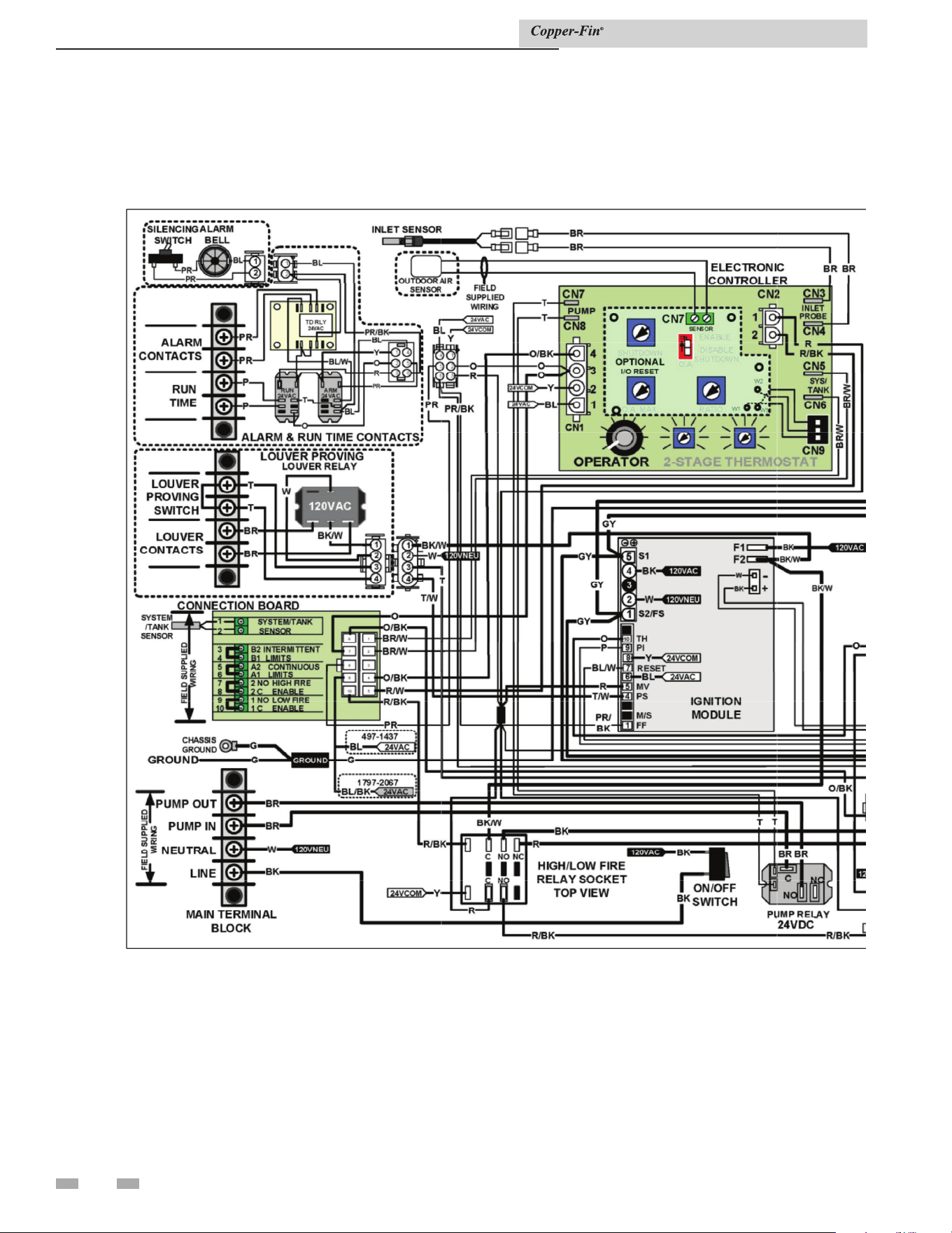
68
10 Diagrams
Ladder diagram
Installation & Service Manual
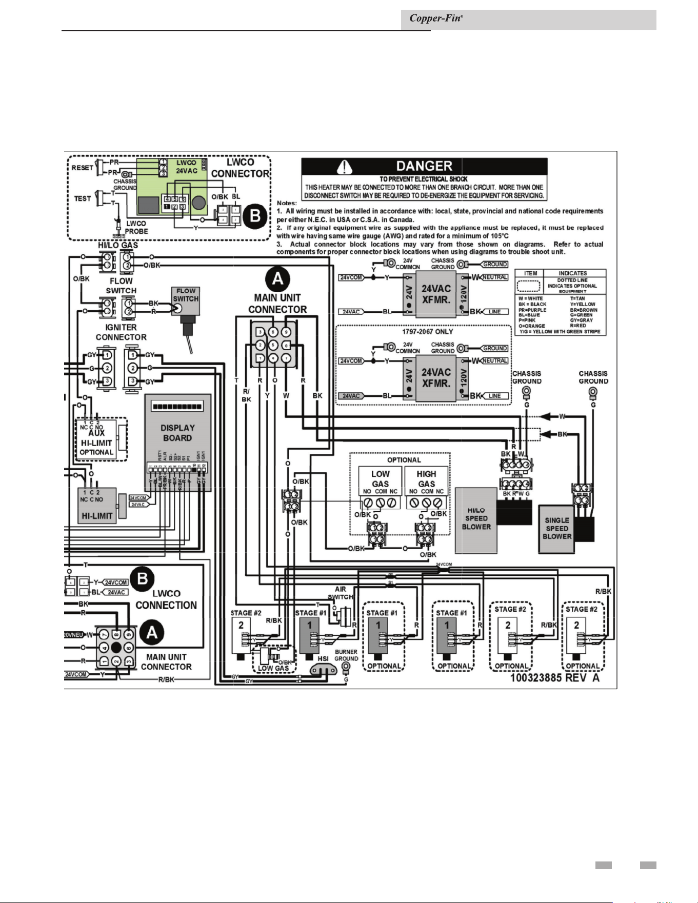
69
10 Diagrams (continued)
Ladder diagram (continued)
Installation & Service Manual
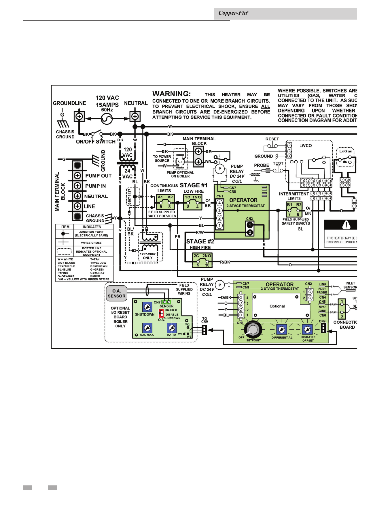
70
10 Diagrams
Connection diagram
Installation & Service Manual
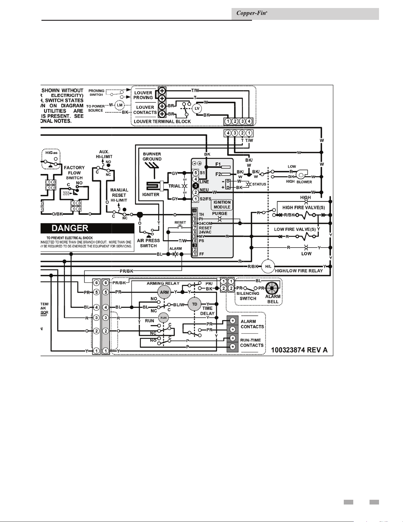
71
10 Diagrams (continued)
Connection diagram (continued)
Installation & Service Manual

Revision Notes: Revision A (ECO #C07390) initial release.
Revision B (ECO C09691) reflects the update of AHRI and ASME logos
on pages 8 and 9.
Revision C (ECO C12077) reflects the update of ignition timing
information on pages 40, 43, 61 and 63 as well as the update of heat
exchanger information on page54.
Revision D (ECO C12972) reflects the addition of the CSA Low Lead
Content logo.
Revision E (ECO C13163) reflects the addition of the Line Voltage
Connections section on page 38 per ECR R06420.
Revision F (ECO C16918) reflects the update of water volume in the
ratings tables on pages 8 and 9 and the correction of Table 3D on page
24 for gas pipe sizing (R07763).
Revision G (PCP# 3000002766 / CN# 500003005) reflects a correction
to images 7-1 through 7-4 on pages 49 through 52. SAP Numbers have
been updated.
Revision H (PCP# 3000006579 / CN# 500006677) reflects the addition
of new venting category information on pages 20 through 21.
Revision J (PCP #3000021634 / CN #500011858) reflects changes
made to water chemistry information on pages 4, 29, 33-37, 48-54,
56-57, and 60.
Revision K (PCP #3000030852 / CN #500020656) reflects an update to
all piping diagrams and the addition of the notice on page 56.
Revision L (PCP #3000033919 / CN #500022621) reflects the input
rates and output rates are revised to match AHRI rounding and comply
with Energy Star turndown rate requirements.
Revision M (PCP #3000037705 / CN #500025906) reflects an update to
the Figure 5-10, ladder diagram, and connection diagram
Revision N (PCP #3000038599 / CN #500026731) reflects an update
to the venting warnings on pages 16 and 22 as well as the addition of
Figure 2-5.
Revision P (PCP #3000042140 / CN #500030042) reflects an update to
the optional outdoor kit information on pages 22-23.
Revision R (PCP #3000043534 / CN #500031265) reflects an update to
FIG. 2-7 and the addition of Table 8A.
Revision T (PCP #3000045219 / CN #500032730) reflects an update to
FIG. 2-7 and Table 2B.
Revision U (PCP #3000051769 / CN #500038677) reflects changes to
table 2C on page 23.
Revision V (PCP #3000053388 / CN #500040014) reflects changes to
the AHRI Rating table on page 8, Table 4B, boiler operation on page 50,
and the addition of Table 6B.
Revision W (PCP #3000057694 / CN #500043851) reflects the addition
of a carbon monoxide warning on page 3.
Revision X (PCP #3000060820 / CN #500046810) reflects the addition
of a dielectric notice on page 51.
100160893_2000001309_Rev X
05/24