CNT-RCV-UM011, Rev 1.1
M30X Integrated Navigation Receiver
Use Manual

M30X Integrated Navigation Receiver
Comnav Technology, LTD.
CNT-RCV-UM011, Rev 1.1
1 INTRODUCTION
1.1 OVERVIEW
Welcome to the user manual for the M30X Integrated Navigation Receiver. This manual describes the
functions of the M30X receiver and provides operational guidance for installation and usage. Detailed
explanations of each operation step and command are provided herein.
This manual also includes specifications for the product hardware and ComNav software. Some
parameters may require supplementary information from the technical reference manual of the equipment
being used.
This manual assumes you are familiar with Global Navigation Satellite System (GNSS) principles and
terminology such as RTK, baud rate, PJK, etc.
1.2 USING THIS MANUAL
This manual is organized into eight main sections as follows:
Chapter 2 Product Overview
Introduces the features, interfaces, and wiring instructions of the M30X Integrated Navigation
Receiver.
Chapter 3 Installation Instructions
Describes the installation methods for the receiver.
Chapter 4 Receiver Configuration
Describes the receiver configuration methods.
Chapter 5 Message Description
Describes the structure of the data messages.
Chapter 6 Coordinate System Description
Describes the usage of different coordinate systems.
Chapter 7 Troubleshooting
If you encounter issues while using the receiver, you can refer to the solutions in the
troubleshooting section to resolve them.
M30X Integrated Navigation Receiver
Comnav Technology, LTD.
CNT-RCV-UM011, Rev 1.1
Chapter 8 Precautions
Lists important notes for using the receiver.
1.3 DISCLAIMER
This warranty applies only to products and manuals that have not been modified or misused, and when
products and software are installed, configured, connected, repaired, stored, and operated in compliance with
ComNav's official manuals and specifications. ComNav shall not be liable for problems or performance issues
caused by:
Use in combination with hardware, software, information, data, systems, interfaces, or devices
not manufactured, supplied, or specified by ComNav;
Any operation of the product or software beyond ComNav's standard specifications;
Unauthorized modification or misuse of the product or software;
Normal wear of consumables (e.g., cables and other accessories).
1.4 CONTACT INFORMATION
From the date of purchase, users receive long-term technical support and upgrade services from
ComNav Technology Ltd. For assistance, please contact us. You may also visit our official website
for the latest software updates and technical documents.
ComNav Technology Ltd.
Address
Building 2, No. 618 Chenglu Middle Road, Jiading District, Shanghai, China
Postal Code
201801
Tel
(021)39907000
Fax
(021)54309582
E-mail
Website
www.sinognss.com
M30X Integrated Navigation Receiver
Comnav Technology, LTD.
CNT-RCV-UM011, Rev 1.1
2 PRODUCT OVERVIEW
2.1 HOST APPEARANCE & MAIN FEATURES
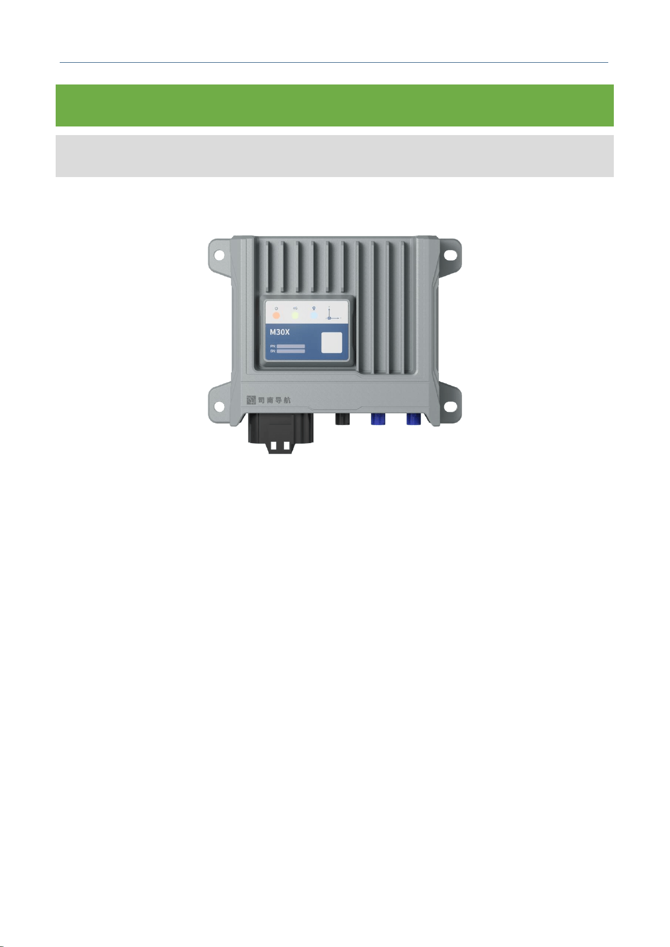
The appearance of the M30X Integrated Navigation Receiver host is shown in Figure 1 below;
Figure 1. M30X Integrated Navigation Receiver
Key Features:
Upgraded wireless transmission, supporting 4G and Bluetooth communication;
Automotive-grade design, IMU meets ASIL B level requirements;
Self-developed Integrated Navigation Algorithm 4.0, adaptable to multiple motion models;
Rich interfaces, supporting Automotive Ethernet, CAN, Serial Port, PPS, USB, etc., and
supports external wheel speed input;
Supports high dynamic rate, with 100Hz data output and data storage.
M30X Integrated Navigation Receiver
Comnav Technology, LTD.
CNT-RCV-UM011, Rev 1.1
2.2 PACKING LIST
Please inspect the package contents upon receipt. Contact ComNav if items are missing or
damaged.
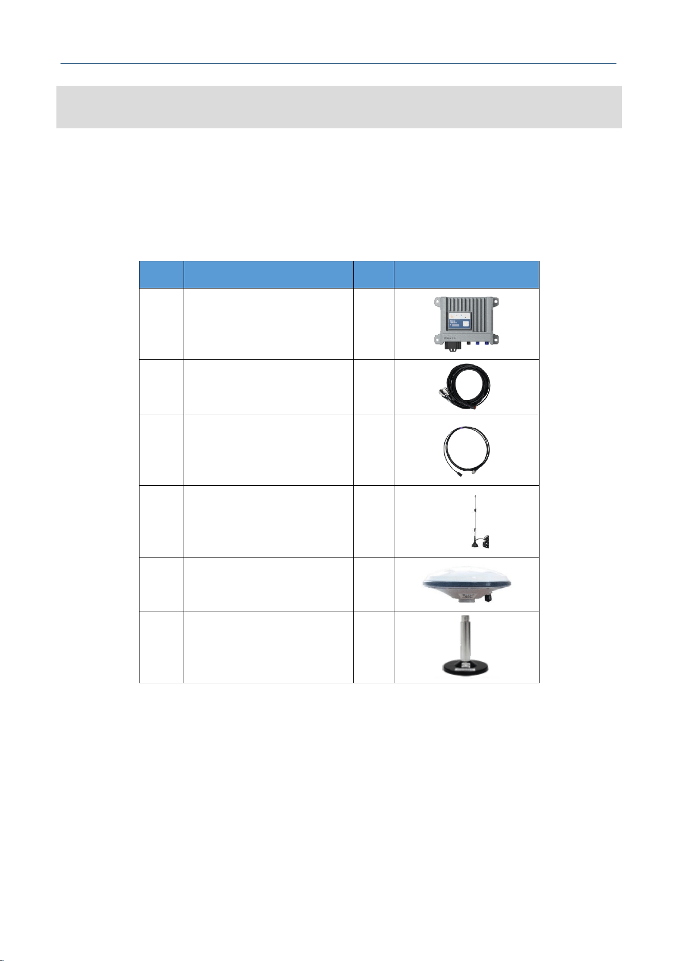
Table 1. M30X System Package Packing List
No.
Item Name
Qty
Picture
1
M30X Main Unit
1
2
18-Pin Data Cable
1
3
FAKRA GNSS Antenna Cable
(Blue), 3 m
2
4
4G Antenna (FAKRA), 1.5 m
1
5
GNSS Antenna
2
6
Strong Magnetic Mount
2
M30X Integrated Navigation Receiver
Comnav Technology, LTD.
CNT-RCV-UM011, Rev 1.1
2.3 INTERFACE DESCRIPTION
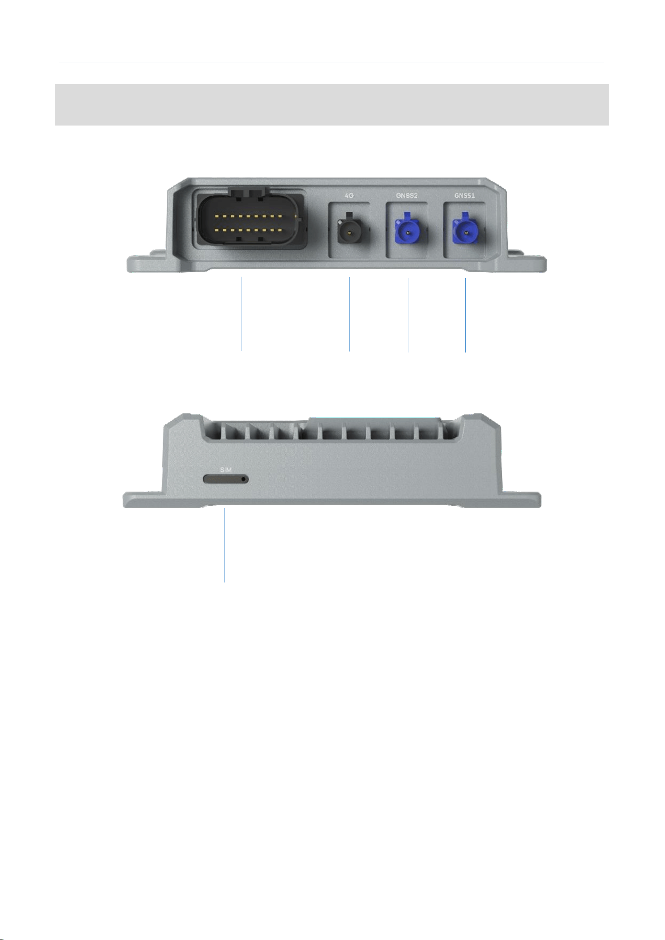
Figure 2. M30X Interface Description
① Data: 18PIN Data Interface (DC + RS232*2 + Automotive Ethernet + PPS + CAN/CAN
FD*2 + USB)
② 4G: 4G Antenna Interface, Fakra-A
③ GNSS2: Secondary GNSS Antenna Interface, Fakra-C
④ GNSS1: Primary GNSS Antenna Interface, Fakra-C
⑤ SIM: NANO SIM Card Slot
①
②
③
④
⑤
M30X Integrated Navigation Receiver
Comnav Technology, LTD.
CNT-RCV-UM011, Rev 1.1
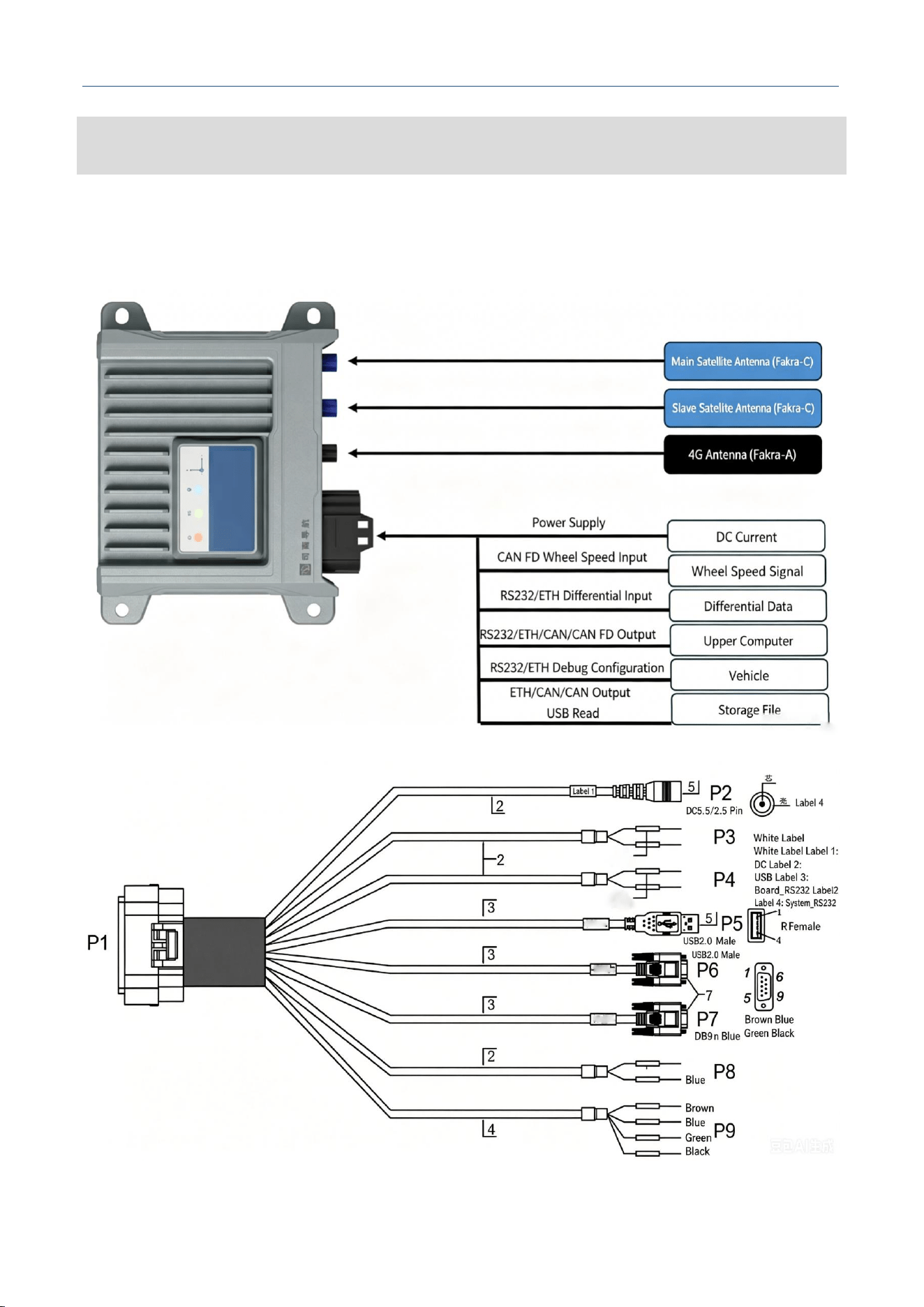
2.4 INDICATOR DESCRIPTION
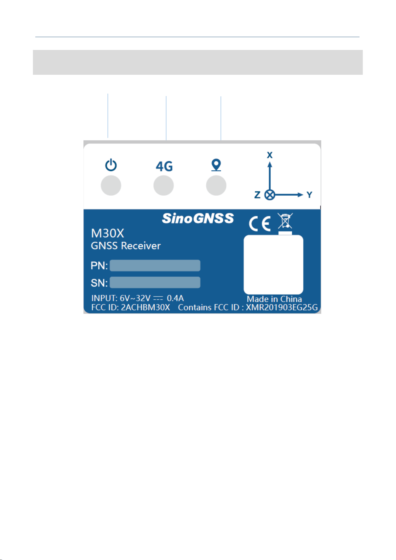
Figure 3. M30X Indicator Description
① Power Indicator: Red steady ON (Normal power supply status)
② 4G: 4G Indicator (Green):
Green blinking: No network / Dial-up failed;
Green fast blinking: 4G communication is normal.
③ Status Indicator (Red/Blue):
OFF: No IMU detected, no GNSS satellite signal detected;
Red blinking: IMU detected, but no GNSS satellite signal, no positioning;
Red steady ON: GNSS positioning available, but IMU abnormal, not detected;
Blue blinking: INS is initializing;
Blue steady ON: INS is in integrated navigation mode.
①
②
③
M30X Integrated Navigation Receiver
Comnav Technology, LTD.
CNT-RCV-UM011, Rev 1.1
2.5 WIRING INSTRUCTIONS
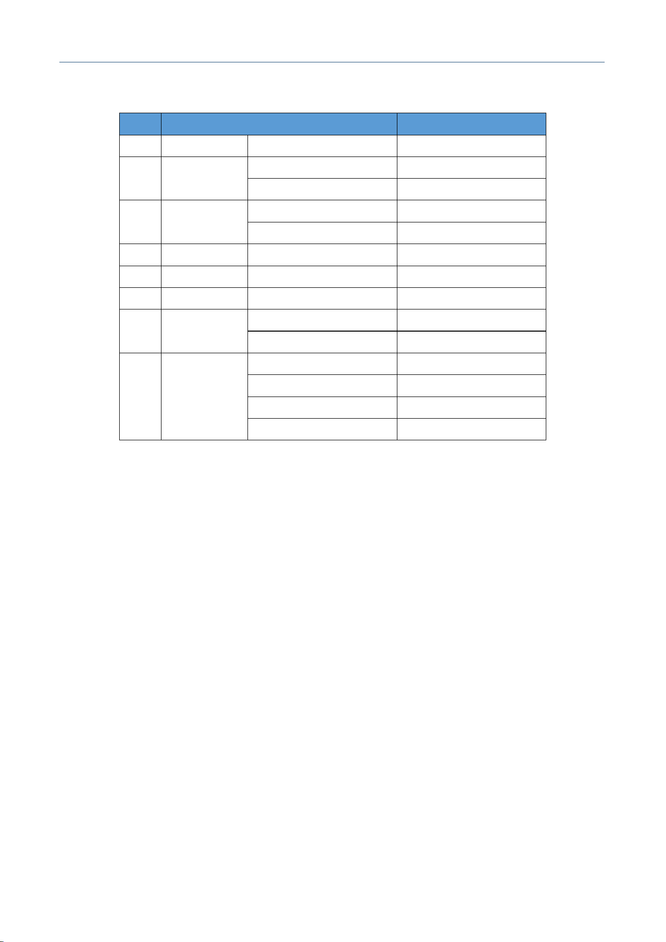
This section describes the connection methods for the product. The connection of each accessory to the
host is shown in the figure below:
Figure 4. M30X Wiring Diagram
M30X Integrated Navigation Receiver
Comnav Technology, LTD.
CNT-RCV-UM011, Rev 1.1
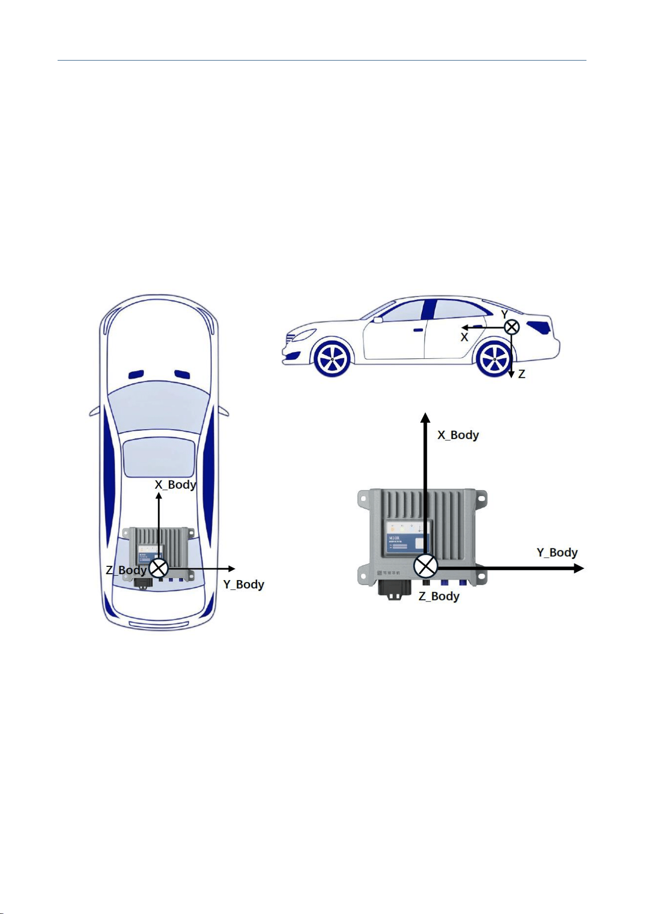
Table 2. Main Interface Pin Description
No.
Signal Definition
Description
1
P2
DC
2
P3
CAN1H
CAN1 High
CAN1L
CAN1 Low
3
P4
CAN2H
CAN2 High
CAN2L
CAN2 Low
4
P5
USB
USB
5
P6
COM1
Serial port 1
6
P7
COM2
Serial port 2
7
P8
PPS
PPS 5V
GND
Power ground reference
8
P9
ENET_P
Etherne P
ENET_N
Ethernet N
VCC
12V_OUT
GND
GND
The connection instructions for the M30X GNSS Receiver and accessories are as follows:
1. Connecting GNSS Antenna Cables: Connect the Fakra-C (Blue) antenna cable Fakra connector to
the receiver's Fakra RF port respectively. Note the distinction between primary and secondary
antennas.
2. Connecting 18-core Data Cable: Align the clip on the 18-pin male connector of the data cable with
the receiver's female port, then insert it.
3. Connecting Power: After connecting the 18-core data cable to the receiver, connect the DC power
connector on the data cable to an external power supply or battery. The receiver will power on
automatically. (Note: Do not reverse the polarity of the external power supply. The input voltage
must be DC 6V~32V)
4. Connecting Serial Port: The M30X is equipped with two serial ports, COM1 and COM2. Connect
the DB9 female end of the data cable to a computer or other communication device to transmit

M30X Integrated Navigation Receiver
Comnav Technology, LTD.
CNT-RCV-UM011, Rev 1.1
integrated navigation messages via commands. (Note: The baud rate of the external sensor must
match that of the receiver)
5. Connecting Automotive Ethernet: After connecting the 18-core data cable to the receiver, connect
the automotive Ethernet wires at the other end of the cable to other automotive Ethernet
communication devices. If you need to connect to a computer or other industrial Ethernet devices,
you need to use an Automotive Ethernet to Industrial Ethernet converter. The Ethernet port supports
IPv4 network layer, TCP/UDP transmission, which can be used for remote debugging, receiving
differential data, outputting position and attitude information, or firmware upgrade.
6. Connecting CAN/CAN FD: After connecting the 18-core data cable to the receiver, connect the
bare wires at the other end to your synchronization device. The GND signal must be connected to
the ground of your device. The M30X provides PPS as a time synchronization signal, which can be
used as needed. The device outputs PPS pulse signal by default, whose rising edge is synchronized
with GPS time, with a synchronization accuracy of 20ns when GNSS signal is good.
7. Connecting Odometer: The M30X supports odometer connection. Wheel speed information can be
forwarded to the M30X according to the DBC protocol, which improves the integrated navigation
positioning accuracy when satellite signal is lost. Please configure this as needed.
8. Connecting USB: You can copy the message files stored on the M30X via the USB interface. After
connecting the 18-core data cable to the receiver, connect the USB interface to a computer to
perform data copy operations.

M30X Integrated Navigation Receiver
Comnav Technology, LTD.
CNT-RCV-UM011, Rev 1.1
3 INSTALLATION INSTRUCTIONS
Please read this section carefully before installing the M30X Integrated Navigation Receiver to
avoid affecting positioning results.
3.1 ANTENNA INSTALLATION
First install the GNSS antenna from the package onto the suction cup mount, then rigidly connect
the suction cup mount to the carrier to ensure the antenna does not shift or shake when the carrier
moves. The GNSS antenna should be placed horizontally; if tilting is required, the angle should not
exceed 15°. Meanwhile, the area above the GNSS antenna should be open and unobstructed. Finally,
screw the TNC connector of the RF cable to the antenna's TNC port tightly.
3.2 MAIN UNIT INSTALLATION
The device should be installed stably and rigidly connected to the carrier, ensuring the relative
positions of the device, antenna, and carrier remain fixed. The requirements for the installation area
are as follows:
1. The device should be installed on a rigid structural surface, which requires the flatness of the
surface to be less than 1° (flatness refers to the pitch and roll angle of the rigid surface relative to
the horizontal plane);
2. The heating temperature of interfering units around the device must be lower than 85℃;
3. There should be no vibration interference units within 50cm around the device. Keep away from
vibration sources such as engines, subwoofers, and other locations with strong vibration. The
frequency bands that the IMU needs to avoid are: 15.8kHz-17.8kHz, 28-35.6kHz, 44kHz, 18.3-
20.3kHz, 1.9-2.1kHz;
4. The device should be kept away from locations with complex electromagnetic environment, such as
near lidar, instrument panel, etc.
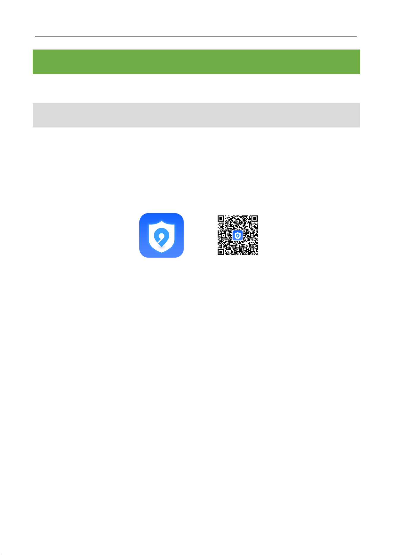
The recommended installation method is shown in Figure 5 below:
1. Horizontal installation, with horizontal angle less than 5°;
M30X Integrated Navigation Receiver
Comnav Technology, LTD.
CNT-RCV-UM011, Rev 1.1
2. The X-axis of the device points to the forward direction of the carrier, the Y-axis is perpendicular to
the forward direction to the right, and the Z-axis points downward;
3. The X-axis of the device should be parallel to the longitudinal central axis of the vehicle, with the
distance as small as possible, less than 70cm;
4. Install the device at or near the center of the carrier's rear axle;
If the device orientation does not meet the above requirements, you can also use horizontal
deflection arrangement. It is recommended that the deflection angle be an integer multiple of 90°.
Figure 5. M30X Installation Diagram
M30X Integrated Navigation Receiver
Comnav Technology, LTD.
CNT-RCV-UM011, Rev 1.1
4 RECEIVER CONFIGURATION
The M30X Integrated Navigation Receiver can be configured via the NavMaster APP.
4.1 APP CONFIGURATION
NavMaster APP is an Android application for high-precision GNSS navigation, which supports
status monitoring and parameter configuration for the M30X receiver. You can scan the QR code
below or visit our official website https://www.sinognss.com to download the latest installation
package and technical documents.
Figure. NavMaster APP Icon & Download QR Code
4.1.1 Bluetooth Connection
Operation Steps:
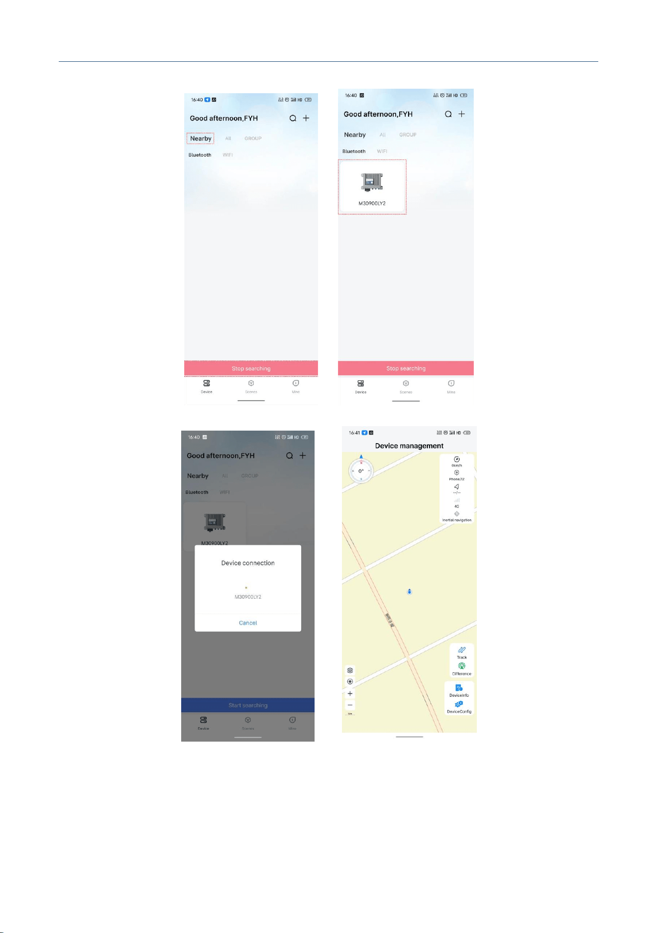
1. Open the APP, select [Nearby], then click [Start Search] (this function requires enabling
Bluetooth on your phone).
2. Search Devices: Available devices will be displayed as shown in the figure.
3. Connect Device: Click the device in the list to initiate connection.
4. Connection Successful: After successful connection, the APP will enter the main interface as
shown below.
M30X Integrated Navigation Receiver
Comnav Technology, LTD.
CNT-RCV-UM011, Rev 1.1
Figure. Bluetooth Connection

M30X Integrated Navigation Receiver
Comnav Technology, LTD.
CNT-RCV-UM011, Rev 1.1
4.1.2 Main Interface Description
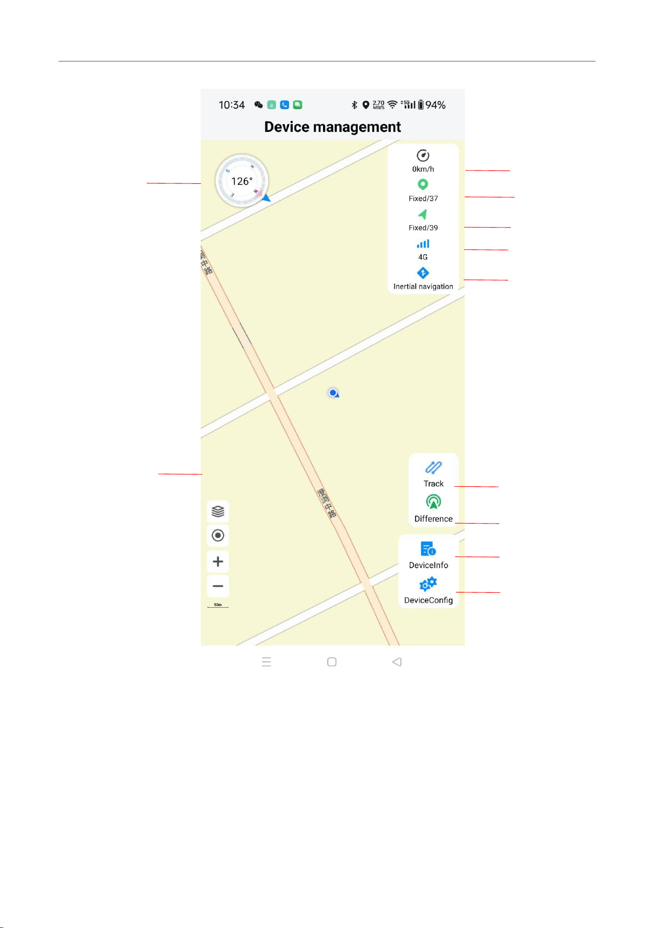
1. Heading Icon: Displays the device's heading value.
2. Speed Icon: Displays the device's moving speed.
3. Positioning Icon: Displays the positioning solution status and satellite count. Click to quickly
enter the Satellite Radar interface.
4. Orientation Icon: Displays the orientation solution status and satellite count. Click to quickly
enter the Satellite Radar interface.
5. 4G Icon: Displays 4G signal strength. Click to quickly enter the 4G interface.
6. INS Icon: Displays the INS initialization status. The icon is gray when uninitialized, and blue
when initialization is successful. Click to quickly enter the Installation Configuration interface.
7. Trajectory Icon: Trajectory button, click to enter the trajectory recording interface.
8. Differential Icon: Displays differential status. The icon is green when differential is available,
gray when not. Click to quickly enter the Differential Configuration interface.
9. Device Info Icon: Click to select the device information to view, including Host Info, Status
Info, Satellite Radar, and Attitude.
10. Device Config Icon: Click to select the parameters to configure, including 4G, Port
Configuration, Data Transmission, Installation Configuration, Data Storage, and Host Control.
11. Map Control Icon: Button '+' zooms in the map, button '-' zooms out the map, button '◎' locks
the device position, button '▤' switches map mode: Satellite Map / Standard Map.
M30X Integrated Navigation Receiver
Comnav Technology, LTD.
CNT-RCV-UM011, Rev 1.1
Figure. Main Interface Description
4.1.3 Host Information
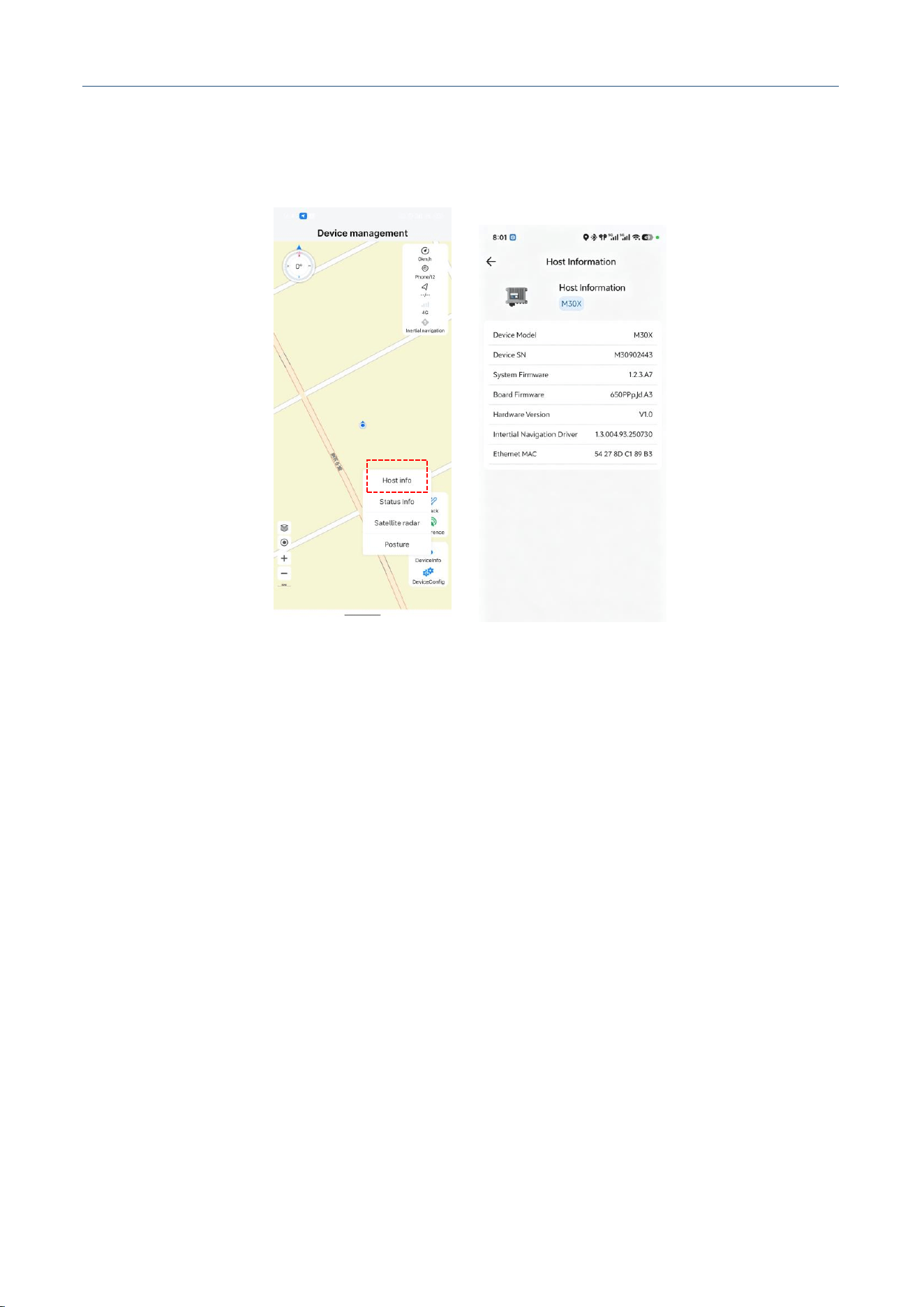
Operation Steps:
1. Click [Device Info].
2. Click [Host Info].
Heading Angle
Speed
Position
Heading
4G
IMU
Trajectory
RTK
Device Information
Device Parameters
MAP
M30X Integrated Navigation Receiver
Comnav Technology, LTD.
CNT-RCV-UM011, Rev 1.1
3. View device model, device SN, system firmware version, board firmware version, hardware version,
INS driver, and Ethernet MAC. The normal display is as shown in the figure.
Figure. Host Information
4.1.4 Status Information
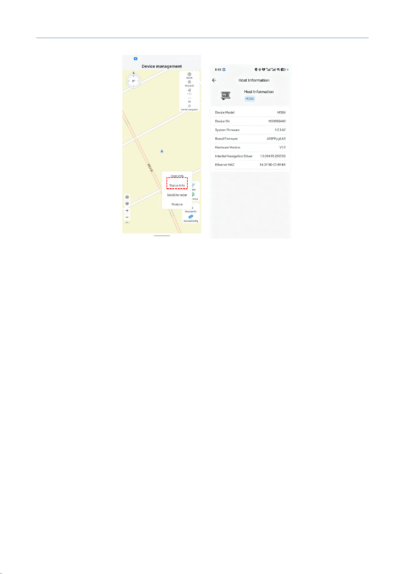
Operation Steps:
1. Click [Status Info].
2. View the status of Data Storage 1 and 2, storage capacity, differential source, INS self-test status,
INS status (Initialized / Uninitialized), and 4G startup status.
M30X Integrated Navigation Receiver
Comnav Technology, LTD.
CNT-RCV-UM011, Rev 1.1
Figure. Status Information
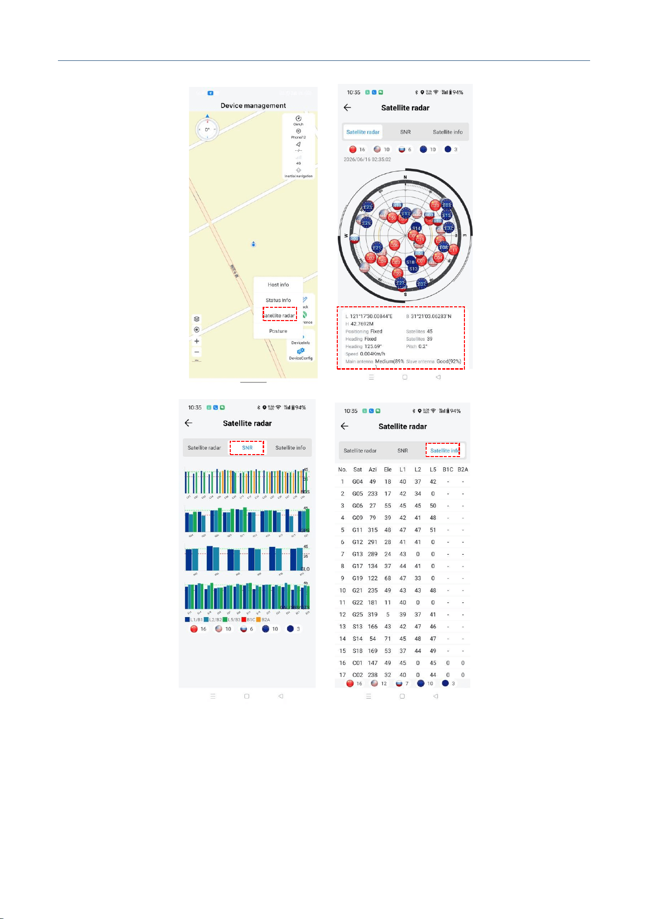
4.1.5 Satellite Radar
Operation Steps:
1. Click [Satellite Radar]: Displays UTC time, sky plot, and positioning information. Positioning
information includes latitude and longitude, positioning status, angle, speed, antenna signal quality,
and HDOP, as shown in the figure.
2. In the [Satellite Radar] interface, click [SNR] to view the satellite SNR bar chart, which intuitively
reflects the satellite signal quality.
3. Click [Satellite Information] on the [Satellite Radar] page to view the satellite search status:
Sat indicates the number of searched satellites (G for GPS, B for BDS, R for GLONASS, and
E for GALILEO). Azi stands for azimuth angle, Ele stands for elevation angle. L1/L2/L5
represent the signal-to-noise ratio of corresponding frequency points, and B1C/B2a refer to
the exclusive signal-to-noise ratio of BDS-3.
M30X Integrated Navigation Receiver
Comnav Technology, LTD.
CNT-RCV-UM011, Rev 1.1
Figure. Satellite Radar
M30X Integrated Navigation Receiver
Comnav Technology, LTD.
CNT-RCV-UM011, Rev 1.1
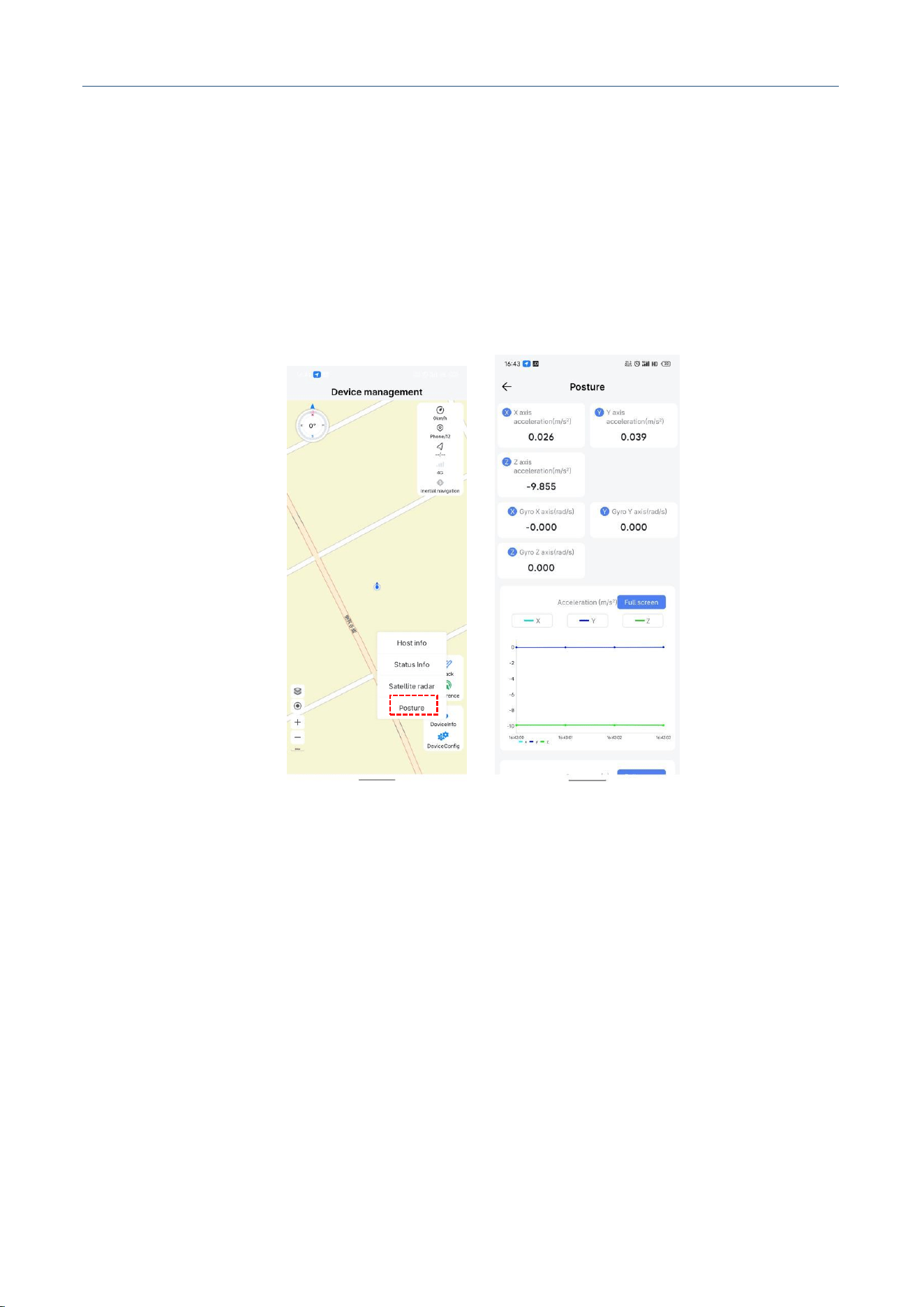
4.1.6 Attitude
Operation Steps:
1. Click [Attitude].
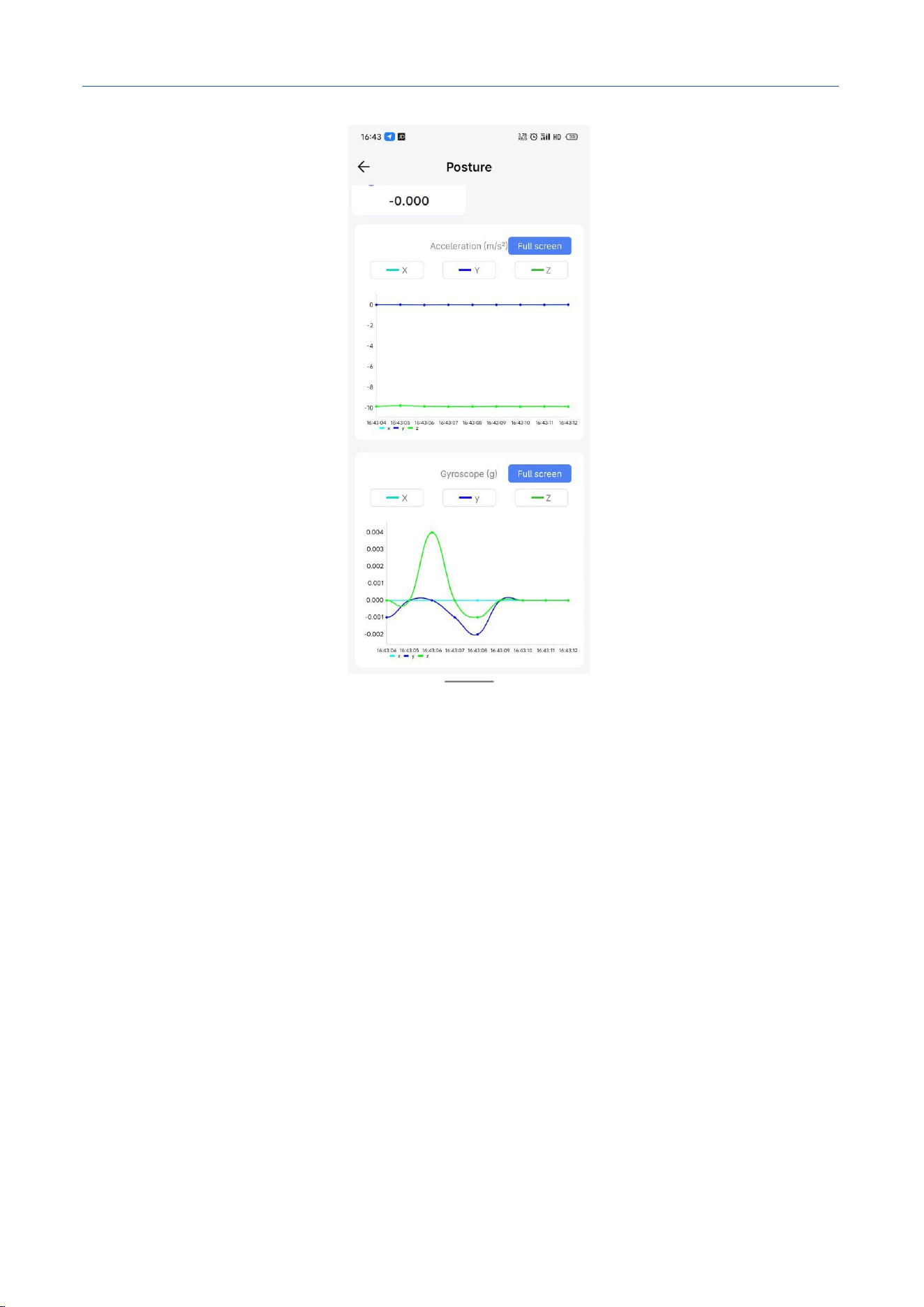
2. View the changes of IMU acceleration and gyroscope values, which can be displayed as dynamic
curves. Swipe down to view the gyroscope curve information, as shown in the figure.
M30X Integrated Navigation Receiver
Comnav Technology, LTD.
CNT-RCV-UM011, Rev 1.1
Figure. Attitude
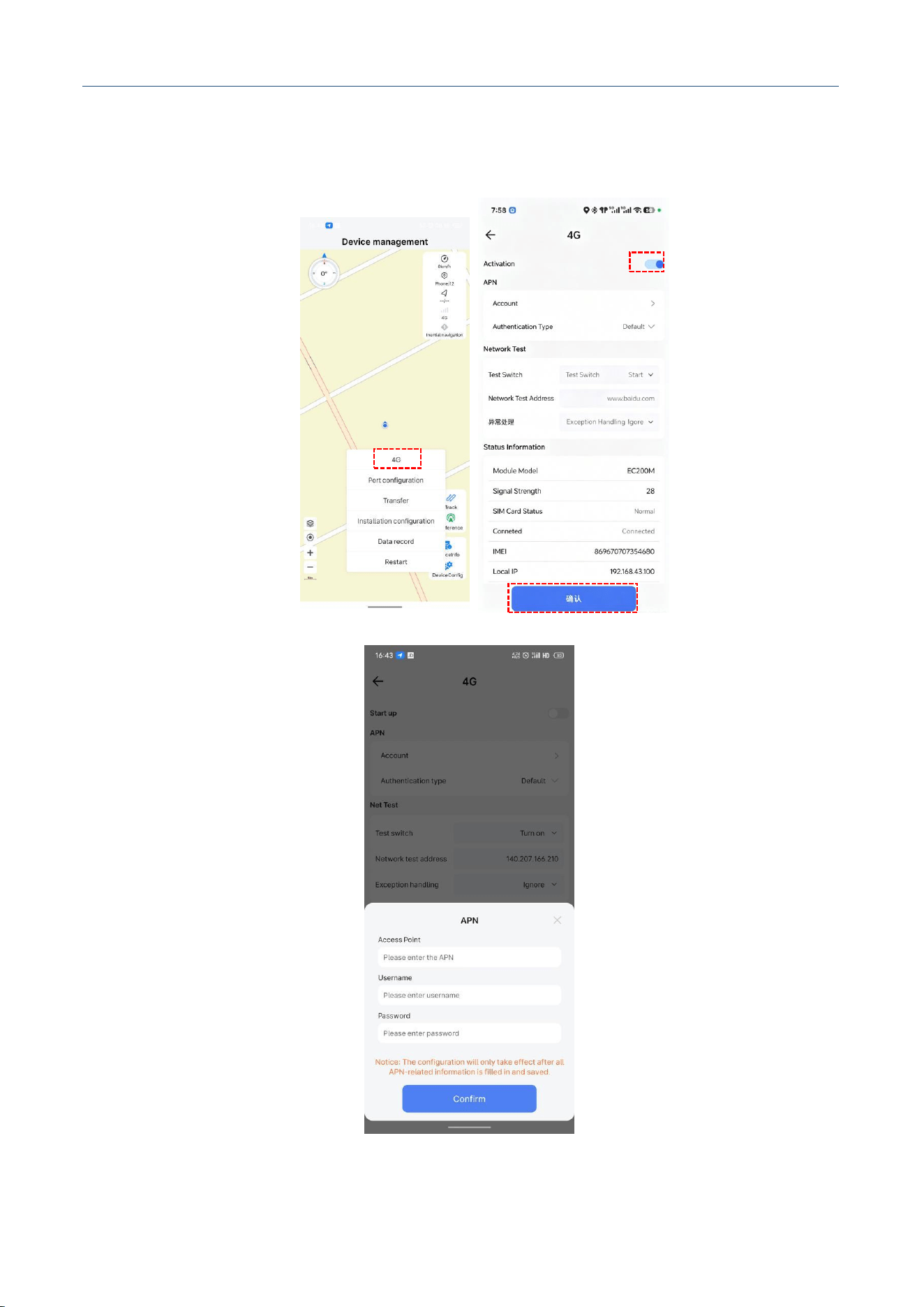
4.1.7 4G Configuration
Operation Steps:
1. Click [Device Config], then click [4G].
2. Turn on the [Switch] for Mobile Network and click Confirm.
3. If 4G connection is normal, the signal strength, SIM status, and network status will be displayed
correctly.
4. Signal Strength: When the signal is between 20 and 30, the strength is normal. There are two SIM
status: Normal when SIM is inserted, No SIM detected when no SIM is inserted. There are two
network status: Normal when network is connected, Not connected when connection failed.
5. If your 4G card is an intranet or private card, you need to set the [APN] separately. The setting
dialog is shown in the figure (you need to turn off the 4G switch first before clicking settings).
M30X Integrated Navigation Receiver
Comnav Technology, LTD.
CNT-RCV-UM011, Rev 1.1
Note: The receiver does not support hot-swapping of 4G SIM cards. Please confirm the SIM card is
inserted before powering on.
Figure. 4G Configuration
M30X Integrated Navigation Receiver
Comnav Technology, LTD.
CNT-RCV-UM011, Rev 1.1
4.1.8 Differential
Operation Steps:
1. Click [Differential] on the main interface.
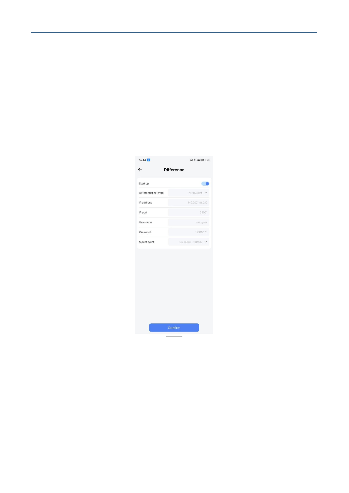
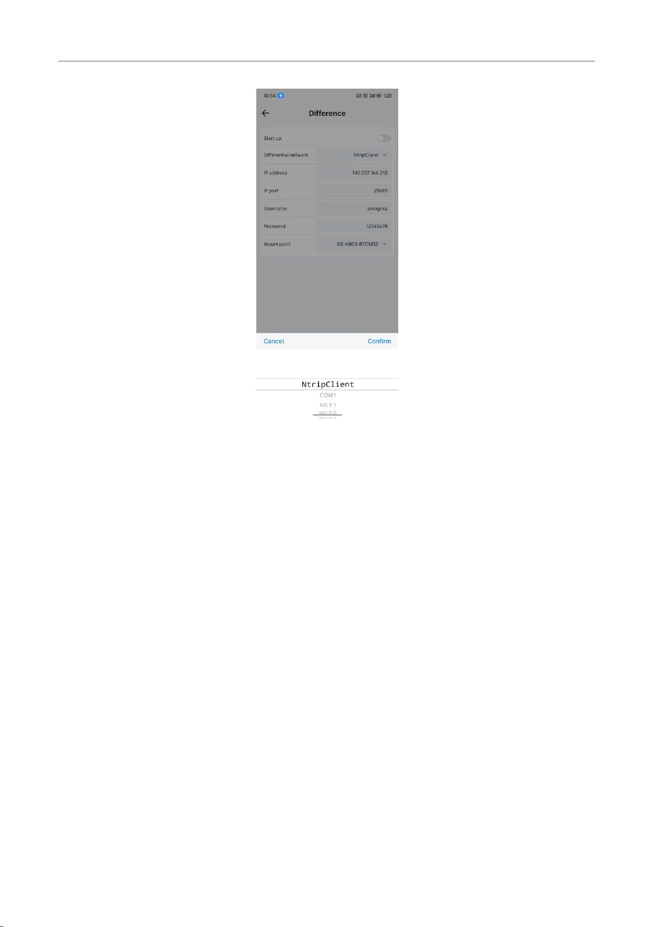
2. Select the network differential source. For network transmission, you can select [Ntrip Client] or
[NET]. For serial transmission, you can select [COM1].
3. When selecting [Ntrip Client], you need to enter the IP address, port, username, password, and
mount point.
Figure. Differential Configuration
4.1.9 Port Configuration
Operation Steps:
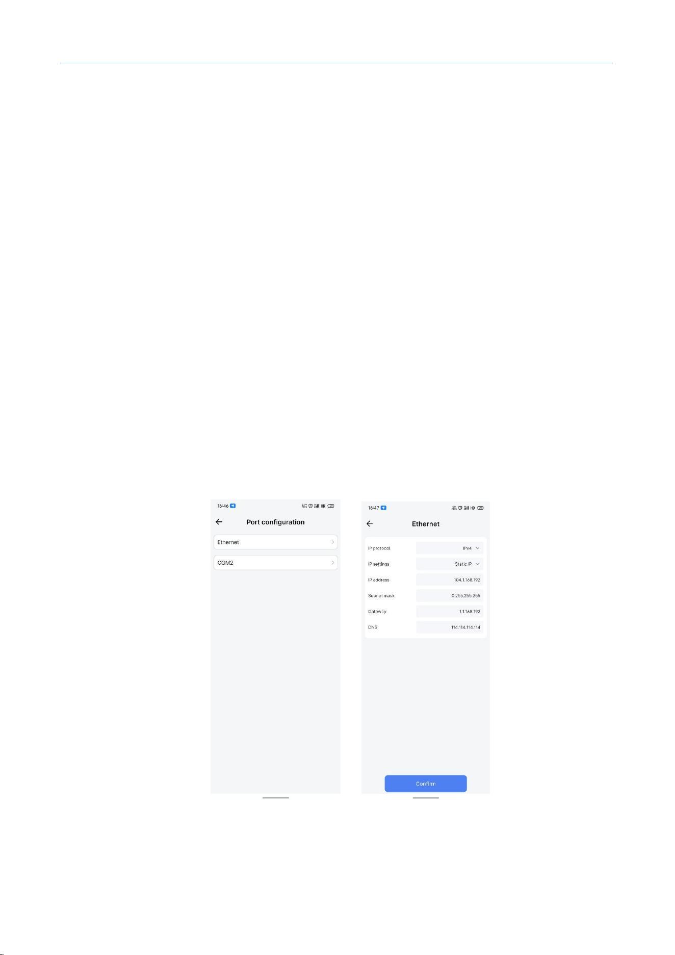
1. Click [Device Config], then click [Port Config] to enter the port configuration interface.
2. Click [Ethernet] to configure the device's Ethernet IP address, subnet mask, gateway, DNS, etc. In
addition, since computers cannot recognize Automotive Ethernet, you need to use a corresponding
M30X Integrated Navigation Receiver
Comnav Technology, LTD.
CNT-RCV-UM011, Rev 1.1
interface converter to enable communication between the computer and the device after configuring
the Automotive Ethernet via the APP.
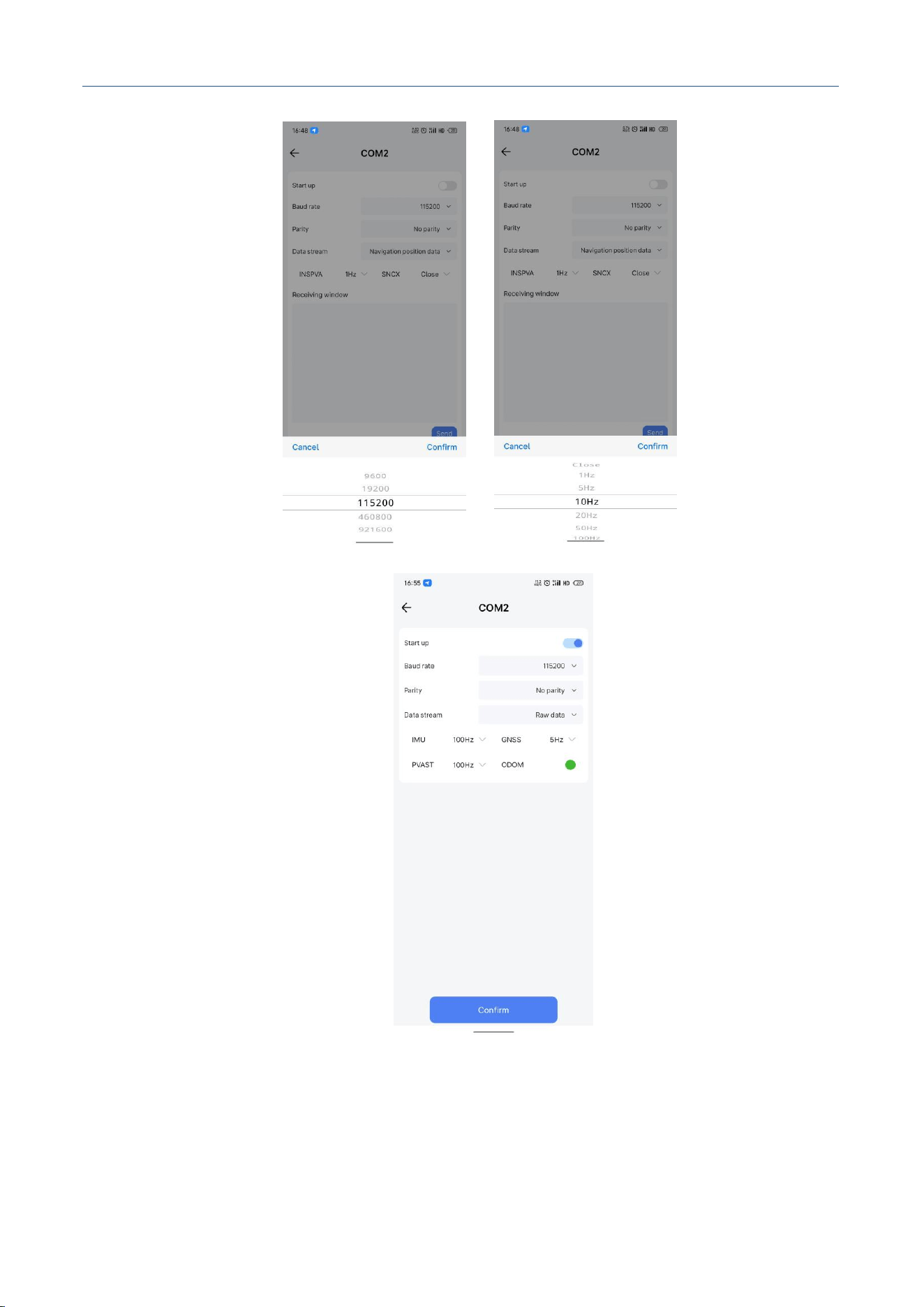
3. Click [COM2] to configure the COM2 serial port baud rate and output messages, including navigation
positioning data INSPVA and SNCX, and raw data IMU and GNSS. The baud rate can be selected
from 9600/19200/115200/460800/921600. The data rate for INSPVA and SNCX can be selected from
1Hz/5Hz/10Hz/20Hz/50Hz/100Hz. The default rate for raw data is IMU 100Hz / GNSS 5Hz / PVAST
100Hz. You can send commands and view the output response in the receive window.
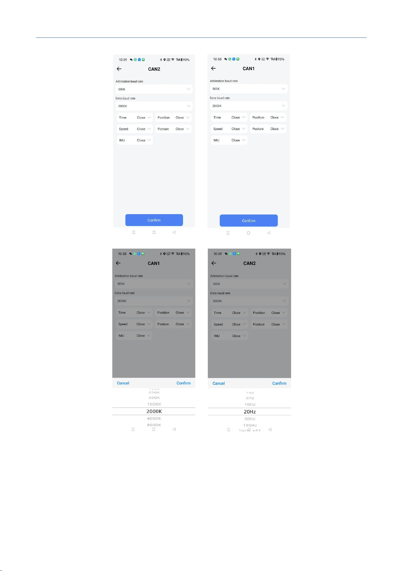
4. Click [CAN1] to configure the CAN1 baud rate and data types, including time, position, velocity,
attitude, and IMU. The arbitration baud rate can be selected from 100K/125K/250K/500K/1000K, and
the data baud rate can be selected from 125K/250K/500K/1000K/2000K/4000K/8000K. The data rate
can be selected from 1Hz/5Hz/10Hz/20Hz/50Hz/100Hz.
5. Click [CAN2] to configure the CAN2 baud rate and data types, including time, position, velocity,
attitude, and IMU. The arbitration baud rate can be selected from 100K/125K/250K/500K/1000K, and
the data baud rate can be selected from 125K/250K/500K/1000K/2000K/4000K/8000K. The data rate
can be selected from 1Hz/5Hz/10Hz/20Hz/50Hz/100Hz.
M30X Integrated Navigation Receiver
Comnav Technology, LTD.
CNT-RCV-UM011, Rev 1.1
M30X Integrated Navigation Receiver
Comnav Technology, LTD.
CNT-RCV-UM011, Rev 1.1
Figure. Port Configuration
4.1.10 Data Transmission
Operation Steps:

M30X Integrated Navigation Receiver
Comnav Technology, LTD.
CNT-RCV-UM011, Rev 1.1
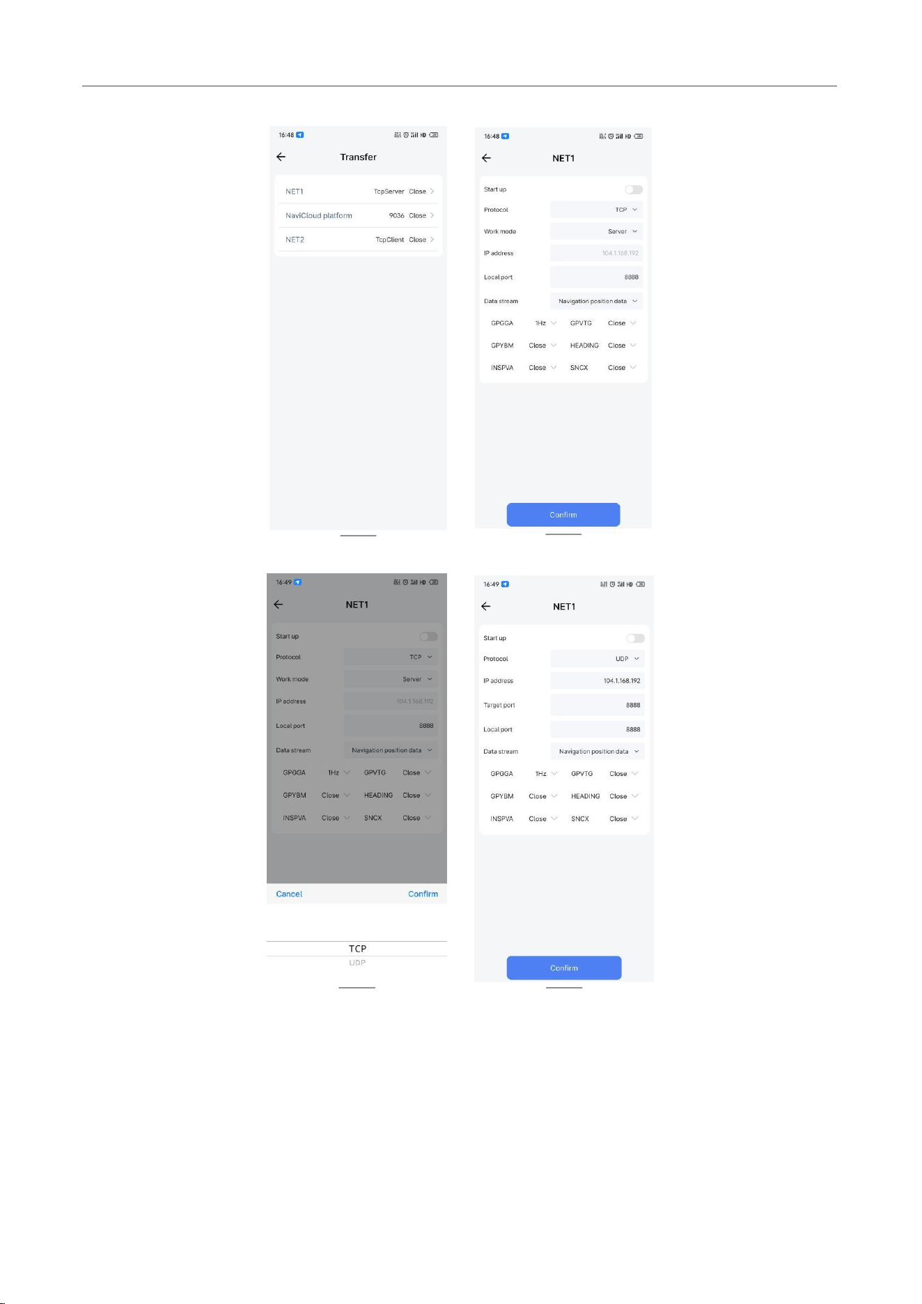
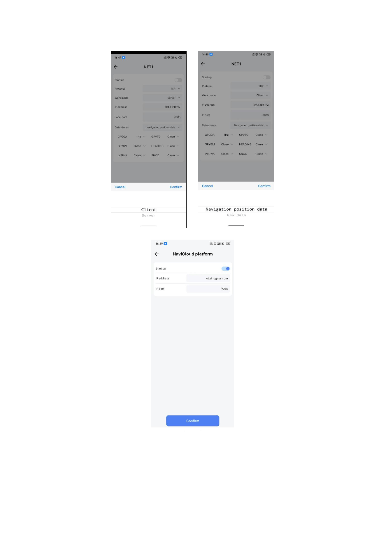
1. Click [Data Transmission] to configure 3 channels of network transmission and the NavCloud
address.
2. Click [NET1], select the protocol TCP or UDP. Under TCP protocol, you can set the device as client
or server, configure the IP address and port, and select the data stream as navigation positioning data
or raw data. The data rate for INSPVA and SNCX can be selected from
1Hz/5Hz/10Hz/20Hz/50Hz/100Hz. The default rate for raw data is IMU 100Hz / GNSS 5Hz / PVAST
100Hz.
3. Click [NET2], select the protocol TCP or UDP. Under TCP protocol, you can set the device as client
or server, configure the IP address and port, and select the data stream as navigation positioning data
or raw data. The data rate for INSPVA and SNCX can be selected from
1Hz/5Hz/10Hz/20Hz/50Hz/100Hz. The default rate for raw data is IMU 100Hz / GNSS 5Hz / PVAST
100Hz.
4. Click [NET3], select the protocol TCP or UDP. Under TCP protocol, you can set the device as client
or server, configure the IP address and port, and select the data stream as navigation positioning data
or raw data. The data rate for INSPVA and SNCX can be selected from
1Hz/5Hz/10Hz/20Hz/50Hz/100Hz. The default rate for raw data is IMU 100Hz / GNSS 5Hz / PVAST
100Hz.
5. Click [NavCloud] to configure the IP address and port of the remote maintenance platform.
M30X Integrated Navigation Receiver
Comnav Technology, LTD.
CNT-RCV-UM011, Rev 1.1
M30X Integrated Navigation Receiver
Comnav Technology, LTD.
CNT-RCV-UM011, Rev 1.1
Figure. Data Transmission
4.1.11 Installation Configuration
M30X Integrated Navigation Receiver
Comnav Technology, LTD.
CNT-RCV-UM011, Rev 1.1
Operation Steps:
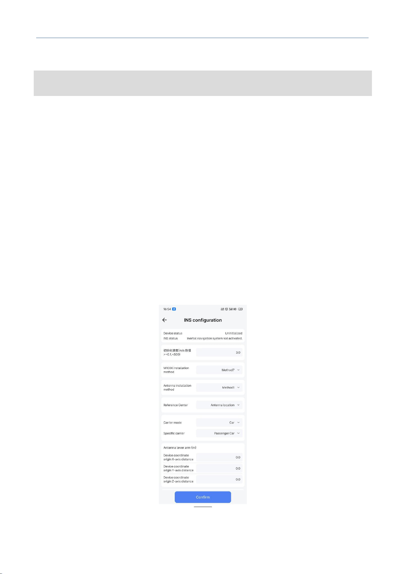
1. Click [Installation Configuration] to enter the device installation parameter configuration interface.
You can configure the device installation method, antenna installation method, carrier model,
antenna lever arm, and rear axle center lever arm.
2. Device Status: Uninitialized, Initialization Complete. Reminds you of the initialization status.
3. INS Status: INS system inactive, INS system aligning, INS alignment complete but insufficient
dynamics for convergence, INS accuracy poor (GNSS signal may be poor), INS in navigation mode
with high accuracy, INS accuracy poor (GNSS signal lost). Normally, after INS convergence is
complete, the INS status will indicate that the INS system has high accuracy.
4. Initialization Speed: Set the minimum speed for INS initialization. The minimum value is 0.1, the
maximum value is less than 500, unit: m/s.
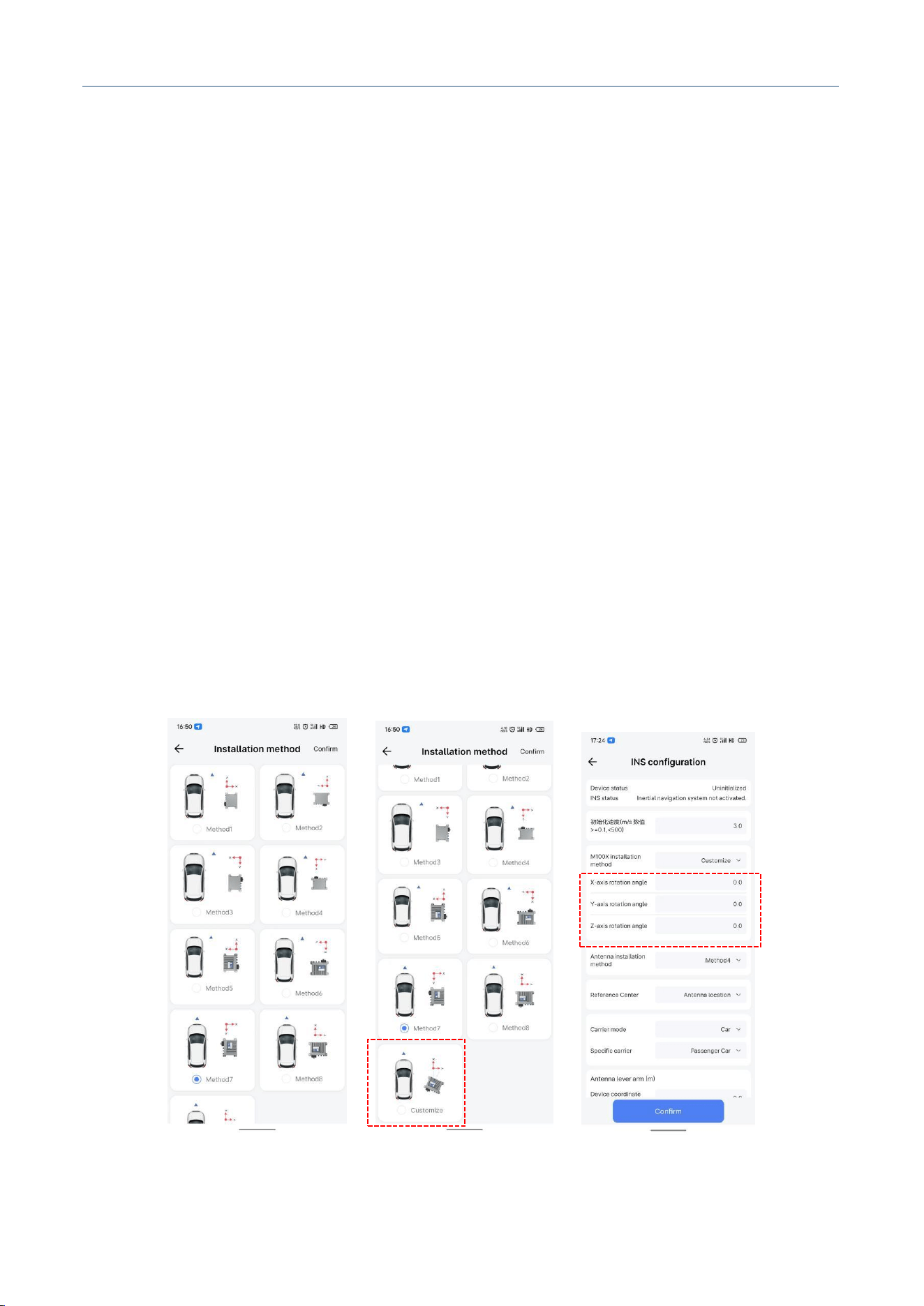
5. Device Installation Method: There are 8 installation methods. Please select the corresponding
method according to the actual installation direction of the device relative to the vehicle's driving
direction. The X/Y axes are the INS reference directions. It also supports custom installation
method. After selecting custom, you need to fill in the specific X/Y/Z axis rotation angles on the
main interface.
Figure. Device Installation Method
M30X Integrated Navigation Receiver
Comnav Technology, LTD.
CNT-RCV-UM011, Rev 1.1
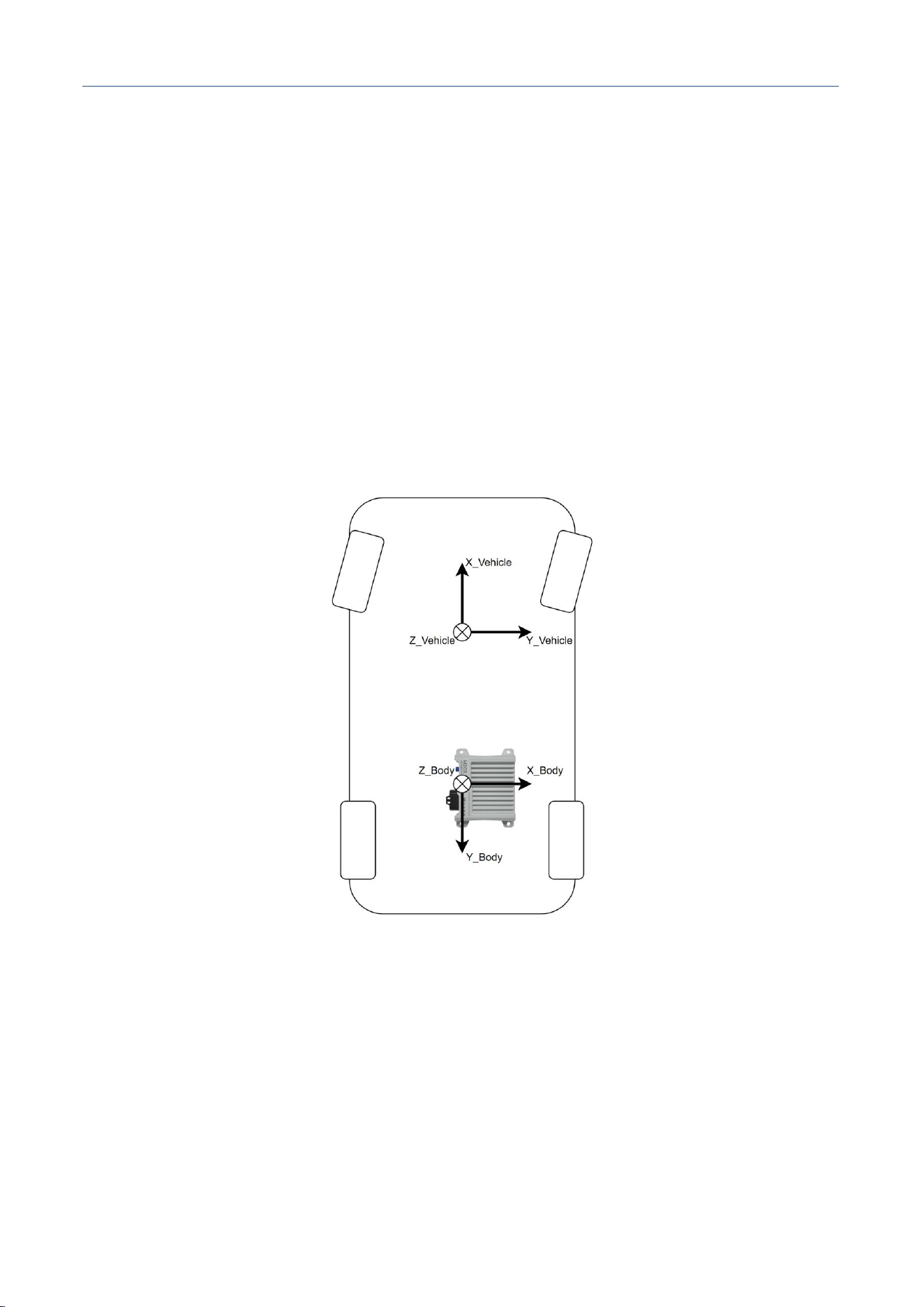
Custom Installation Angle Description:
The attitude deviation between the device coordinate system and the vehicle coordinate system is
called the device rotation parameter or device installation angle, which is essentially the Euler angle
rotation from the device coordinate system to the vehicle coordinate system. The figure below shows
the rotation parameters from the device coordinate system to the vehicle coordinate system.
Where, X/Y/Z represent the rotation angles around the X/Y/Z axes, unit: deg.
The rotation rules are as follows:
Figure. Top View of Vehicle and Device
Take the figure as an example. For this installation method, rotating from the vehicle coordinate
system to the device coordinate system requires rotating 90 degrees around the positive Z axis.
Therefore, the Euler angles from the device coordinate system to the vehicle coordinate system are:
X: 0, Y: 0, Z: 90.
1. Rotate from the Vehicle Frame coordinate system to the Body Frame
coordinate system;
2. Rotate in the order Z → Y → X;
3. The rotation direction of the coordinate axes follows the right-hand rule.
M30X Integrated Navigation Receiver
Comnav Technology, LTD.
CNT-RCV-UM011, Rev 1.1
Note: The Euler angles from the device coordinate system to the vehicle coordinate system should
be measured as accurately as possible. If there is an error in the configured rotation parameters,
online calibration is required.
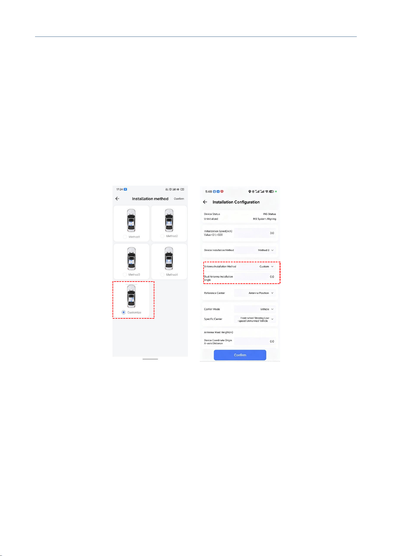
6. Antenna Installation Method: There are 4 installation methods. Please select the corresponding
option according to the actual installation position of the primary and secondary antennas. It also
supports custom installation method. After selecting custom, you need to fill in the specific
installation angle, which is the clockwise rotation angle of the secondary antenna relative to the
primary antenna.
Figure. Antenna Installation Method
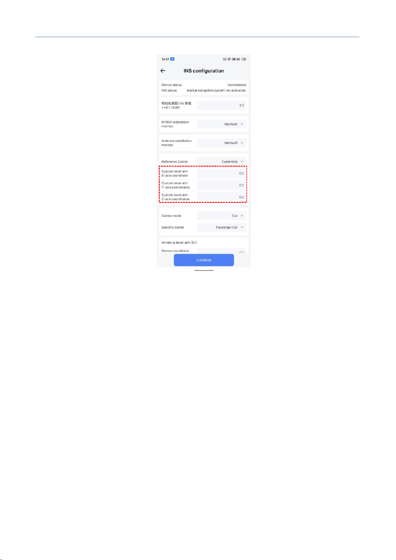
7. Reference Center: The reference center is the actual position where the device outputs the latitude
and longitude coordinates. You can select Primary Antenna Position, Rear Axle Center, or Custom
(Custom means the distance of the selected point relative to the origin of the device coordinate
system along the X/Y/Z axes). For example, if you select Primary Antenna Position, the latitude and
longitude output by the device is actually the position of the primary antenna. If you set the custom
coordinates to 0,0,0, the device will output the position of the origin of the device coordinate system.
M30X Integrated Navigation Receiver
Comnav Technology, LTD.
CNT-RCV-UM011, Rev 1.1
Figure. Reference Center
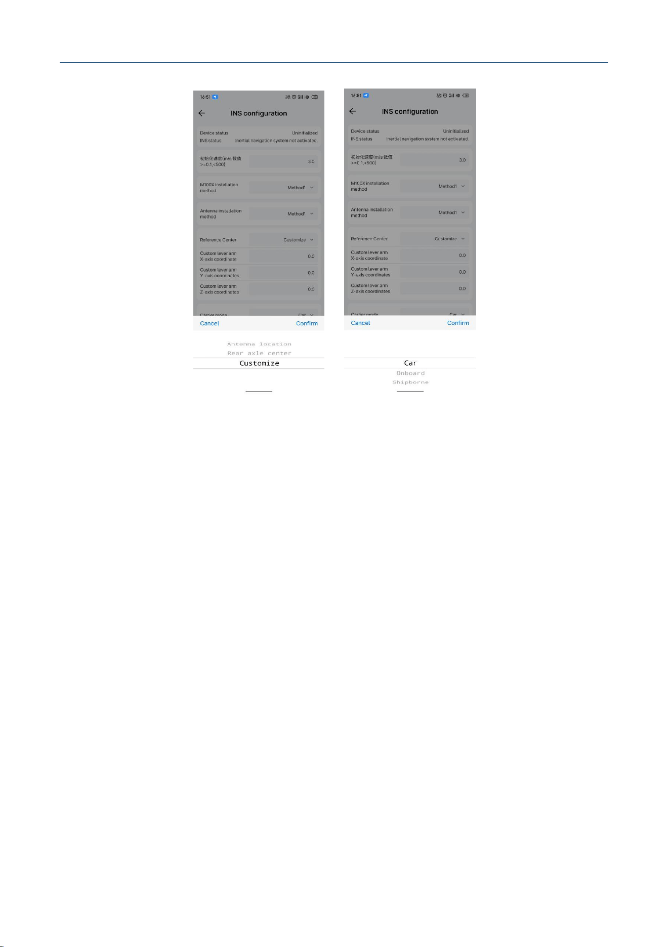
8. Carrier Mode: You can select from three modes: Vehicle, Aircraft, and Ship. Please select the
corresponding model according to your actual carrier.
M30X Integrated Navigation Receiver
Comnav Technology, LTD.
CNT-RCV-UM011, Rev 1.1
Figure. Carrier Mode
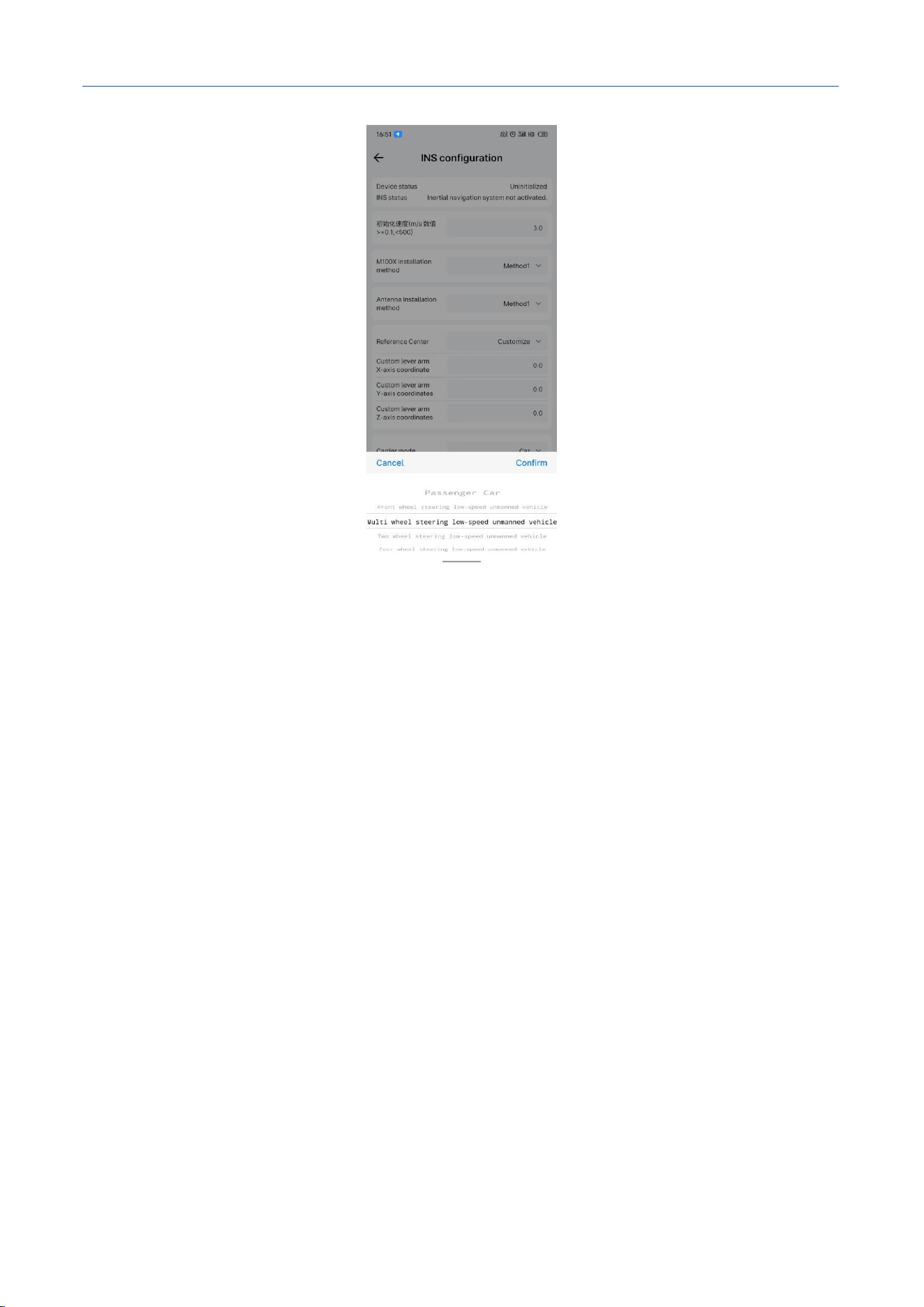
9. Specific Carrier: You can select from Passenger Car, Front-wheel Steering Low-speed UGV, Multi-
wheel Steering Low-speed UGV, Two-wheel Steering Low-speed UGV, Four-wheel Steering Low-
speed UGV. Selecting the corresponding model according to your actual carrier will achieve better
results.
M30X Integrated Navigation Receiver
Comnav Technology, LTD.
CNT-RCV-UM011, Rev 1.1
Figure. Specific Carrier
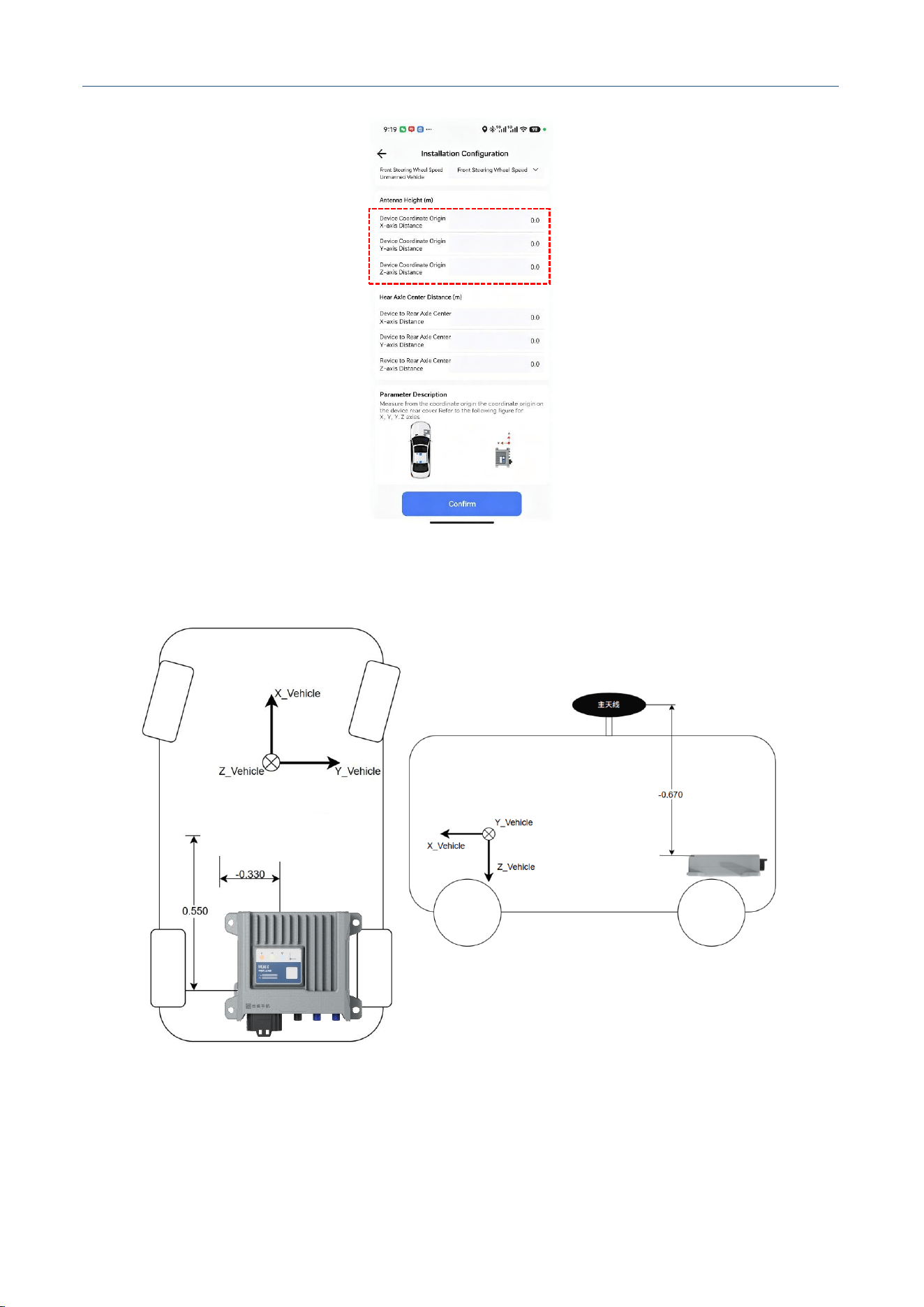
10. Antenna Lever Arm: The vector from the origin of the device coordinate system to the phase center
of the primary GNSS antenna is called the GNSS antenna lever arm. With the center of the device
coordinate system as the origin, the X/Y/Z axes are consistent with the vehicle coordinate system.
Measure the X/Y/Z coordinates of the antenna phase center. Note: Antenna lever arm error will
directly affect the positioning accuracy of the integrated navigation system, so the error should be
less than 2cm as much as possible. If you do not have accurate measurement methods, you can
perform online calibration on the device after configuration.
M30X Integrated Navigation Receiver
Comnav Technology, LTD.
CNT-RCV-UM011, Rev 1.1
Figure. Lever Arm from Device to Primary GNSS Antenna
11. Rear Axle Center Lever Arm: Under normal driving conditions, the lateral and vertical velocity at
the rear axle center are 0. To correctly use the constraint information and improve the vehicle DR
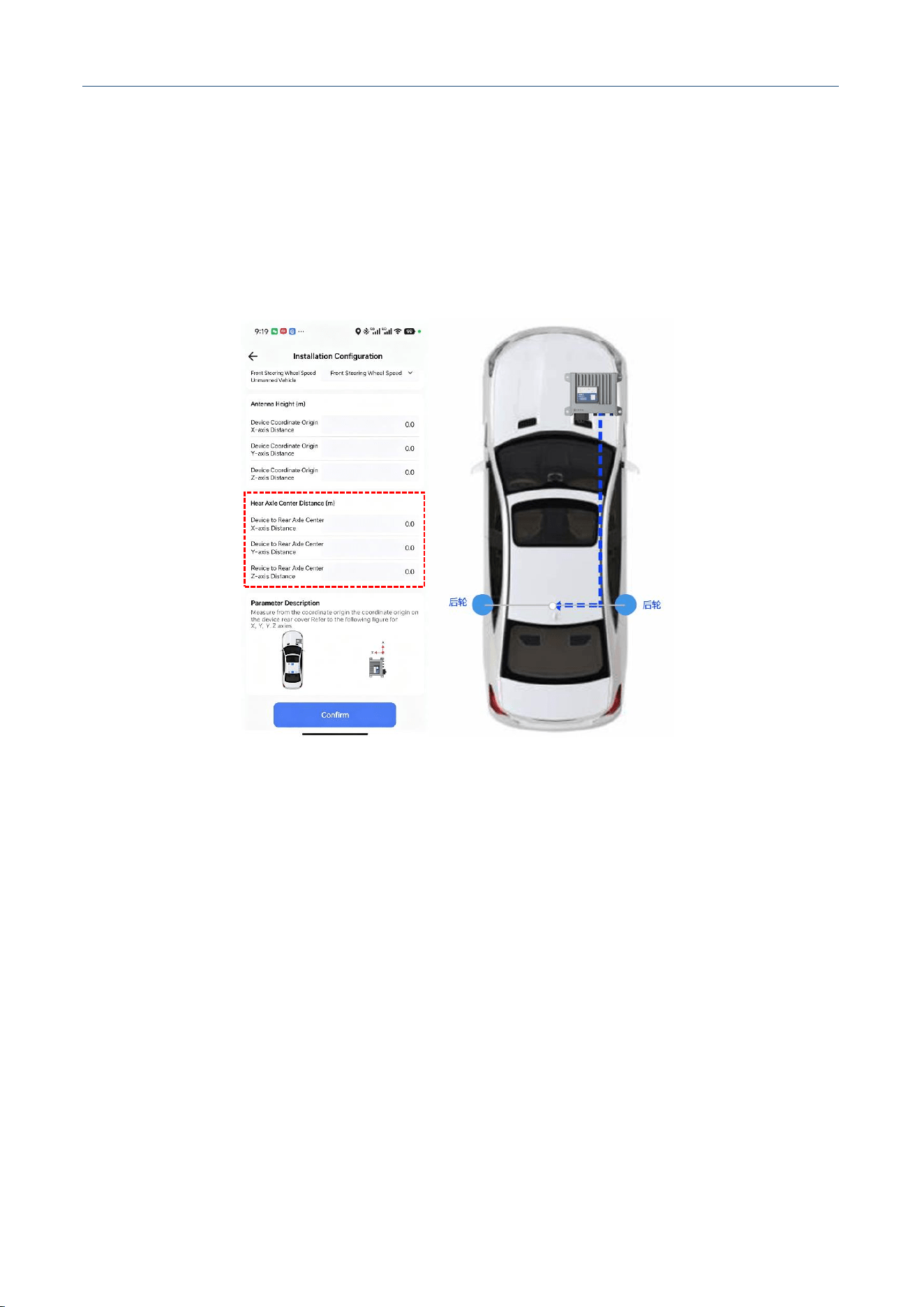
M30X Integrated Navigation Receiver
Comnav Technology, LTD.
CNT-RCV-UM011, Rev 1.1
performance, you need to manually measure the lever arm from the origin of the device coordinate
system to the rear axle center after installing the device. The measurement method can refer to the
GNSS antenna lever arm measurement. Where, X/Y/Z represent the X/Y/Z coordinates of the rear
axle center lever arm, unit: m. After the vehicle is connected with wheel speed data, this
configuration must be set correctly, otherwise it may cause abnormal results.
Figure. Lever Arm from Device to Rear Axle Center
4.1.12 Data Storage
Operation Steps:
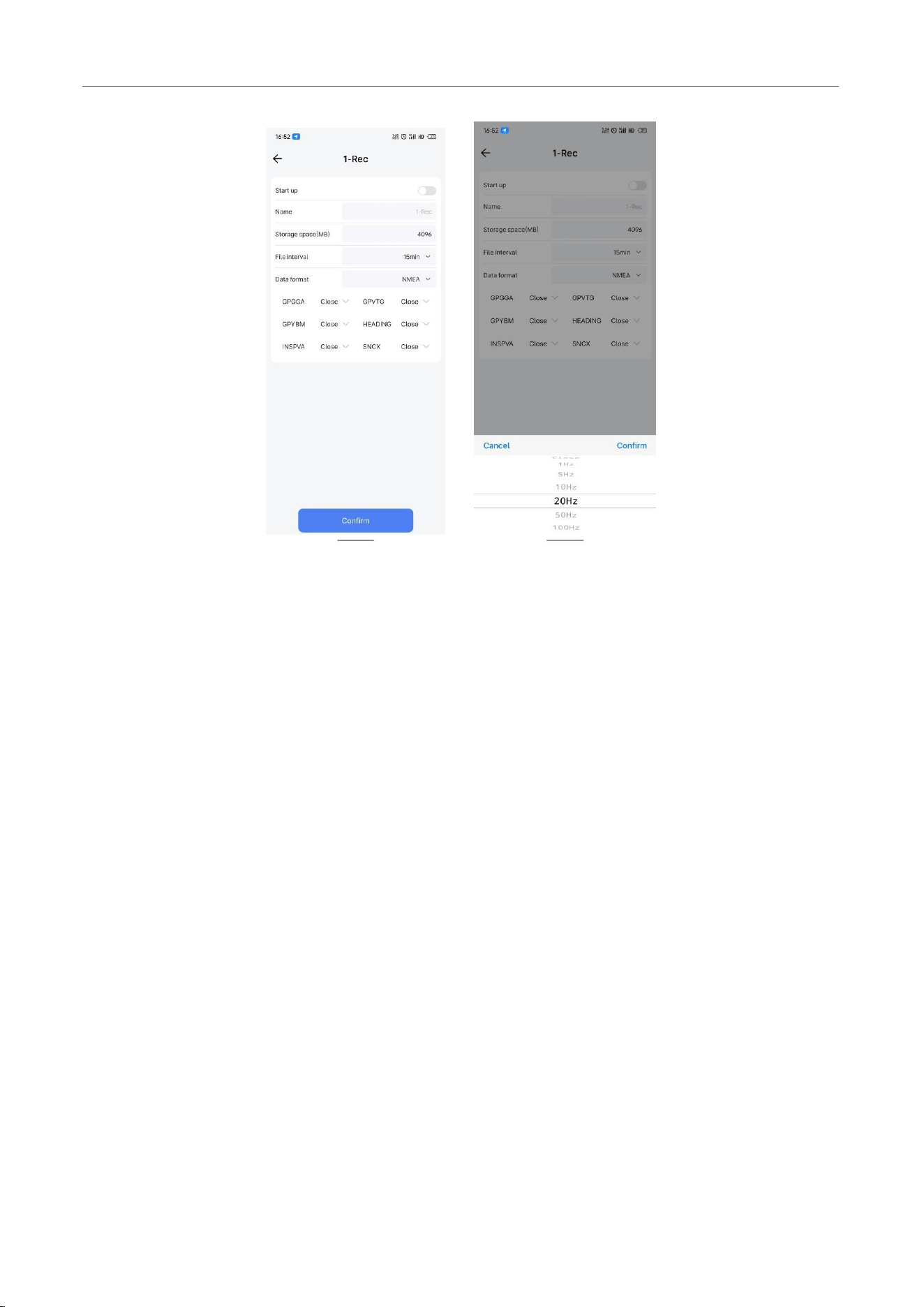
1. Click [Data Storage] to enter the data storage configuration interface. You can view the storage
capacity and configure two storage channels.
2. Click the first storage channel. By default, the first channel can only store navigation messages
INSPVA and SNCX. Select the required message rate, which supports
1Hz/5Hz/10Hz/20Hz/50Hz/100Hz. The storage space and file interval will be allocated according to
the rate. Note: Storing a single 100Hz message for one day requires about 2G storage, and storing
both messages at 100Hz for one day requires about 4G storage. If the storage space is insufficient,
cyclic storage may overwrite the earlier data.
M30X Integrated Navigation Receiver
Comnav Technology, LTD.
CNT-RCV-UM011, Rev 1.1
Figure. First Storage Channel Configuration
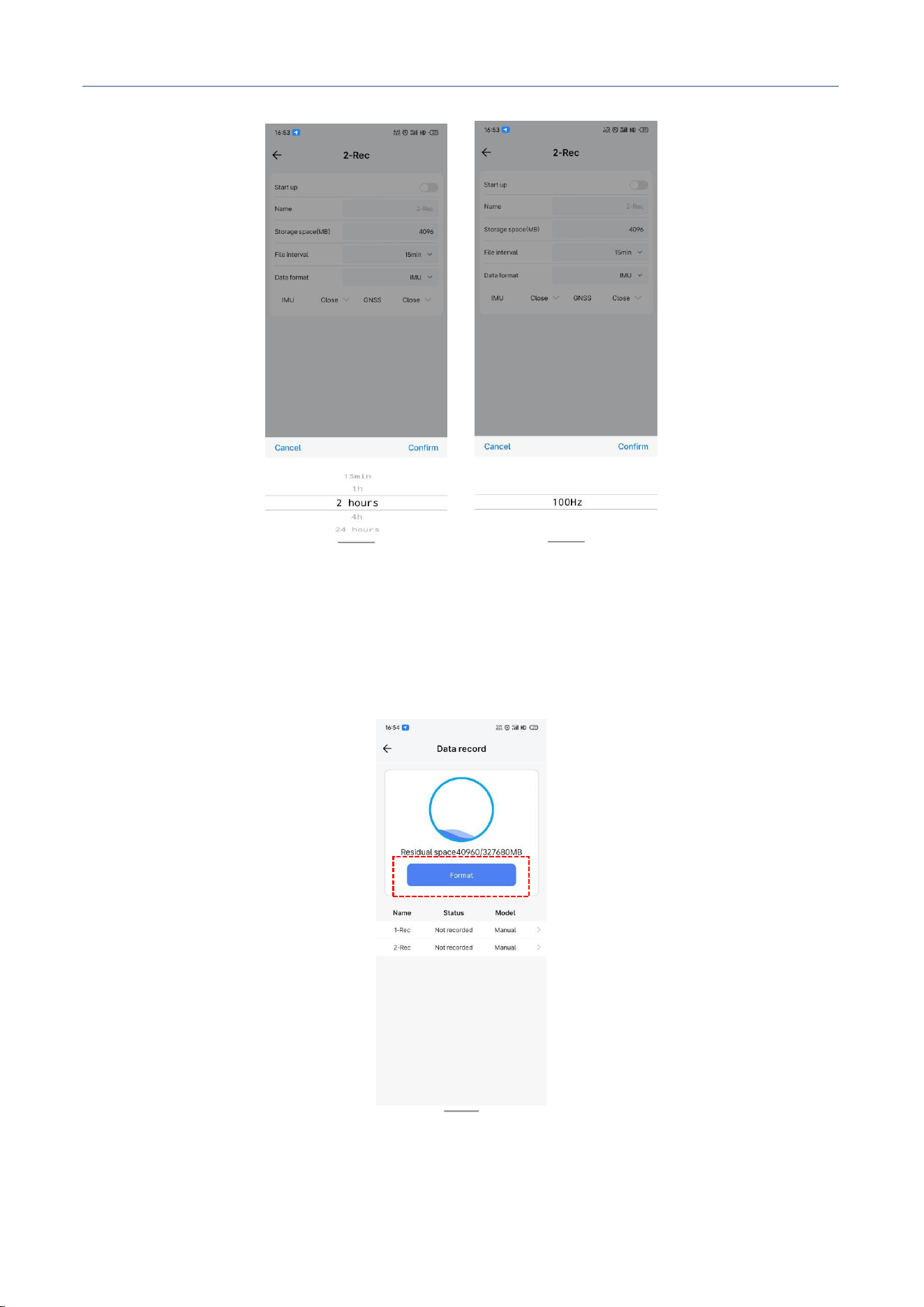
3. Click the second storage channel. By default, the second channel can only store raw messages. The
default rate for IMU data is 100Hz, GNSS data is 5Hz, and PVAST data is 100Hz. It supports
1Hz/5Hz/10Hz/20Hz/50Hz/100Hz. The file interval can be selected from 15min/1h/4h/24h. ODOM
indicates wheel speed access: the indicator is green if wheel speed is connected, otherwise gray.
Note: If the storage space is insufficient, cyclic storage may overwrite the earlier data.
M30X Integrated Navigation Receiver
Comnav Technology, LTD.
CNT-RCV-UM011, Rev 1.1
Figure. Second Storage Channel Configuration
4. Click [Data Storage], then click the Format button to format the storage. The device will restart after
formatting.
Figure. Format Storage
M30X Integrated Navigation Receiver
Comnav Technology, LTD.
CNT-RCV-UM011, Rev 1.1
4.1.13 Host Control
Operation Steps:
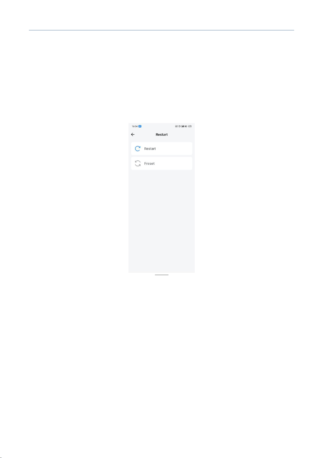
1. Click [Host Control] to enter the host control interface. You can restart the device or restore factory
settings. Restoring factory settings will clear all previous configurations and restart the device,
please operate with caution.
Figure. Host Control
M30X Integrated Navigation Receiver
Comnav Technology, LTD.
CNT-RCV-UM011, Rev 1.1
4.2 USAGE INSTRUCTIONS
Before using the M30X, please ensure that you have completed the antenna installation and device
installation as described in Section 3.1 and 3.2, and the device is powered on. You can confirm whether
the device is powered on and running correctly via the following steps:
1. Check the device indicators: Is the power indicator red steady ON?
2. Is the status indicator red steady ON?
3. Search for the device via Bluetooth in the APP, can you find and connect to it normally?
4. Check the satellite status of the device in the APP.
4.2.1 INS Configuration
Click [Installation Configuration] in the NavMaster APP, and complete the configuration of
initialization speed, device installation method, antenna installation method, reference center, carrier
mode, antenna lever arm, and rear axle center lever arm as described in Section 4.1.10. For details,
please refer to Section 4.1.10.
Figure. Installation Configuration

M30X Integrated Navigation Receiver
Comnav Technology, LTD.
CNT-RCV-UM011, Rev 1.1
4.2.2 Differential Data Input
Differential data is transmitted from the base station to the rover to improve the rover's positioning
accuracy. The data format usually uses the RTCM protocol (RTCM 3.x version).
The base station is a fixed GNSS receiver with known coordinates, which broadcasts differential
data. The rover needs to continuously obtain differential data from the base station to calculate its own
accurate current position.
You can build your own base station or rent a commercial base station. Either way, a link is
required between the base station and rover to transmit differential data. In use, you can build the data
link via the device's 4G function, or with wireless data transmission, or DTU and other devices. As a
rover, the M30X usually obtains differential data via its own 4G function, serial port COM1, or
Ethernet port.
If you obtain differential service via the device's 4G function, you need to insert the SIM card
before powering on the device. After powering on, connect the device via the APP, click the [4G]
function, turn on the 4G switch, click the [Differential] function, and select the differential network
[Ntrip Client] or [NET1] or [NET2] or [NET3]. Selecting [Ntrip Client] means the link uses NTRIP
protocol, selecting [NET] means the link uses TCP protocol. The related IP settings will be mapped to
the corresponding items in [Data Transmission]. For details, please refer to Section 4.1.7.
If you obtain differential data via Ethernet, you need to turn off the device's 4G switch, open [Port
Config]-[Ethernet], and configure the Ethernet IP. After configuration, click the [Differential] function,
select the differential network [Ntrip Client] or [NET1] or [NET2] or [NET3]. Selecting [Ntrip Client]
means the link uses NTRIP protocol, selecting [NET] means the link uses TCP protocol. The related
IP settings will be mapped to the corresponding items in [Data Transmission]. For details, please refer
to Section 4.1.9.
If you obtain differential data via serial port COM1, click the [Differential] function, select the
differential network [COM1].
M30X Integrated Navigation Receiver
Comnav Technology, LTD.
CNT-RCV-UM011, Rev 1.1
Figure. Differential Configuration
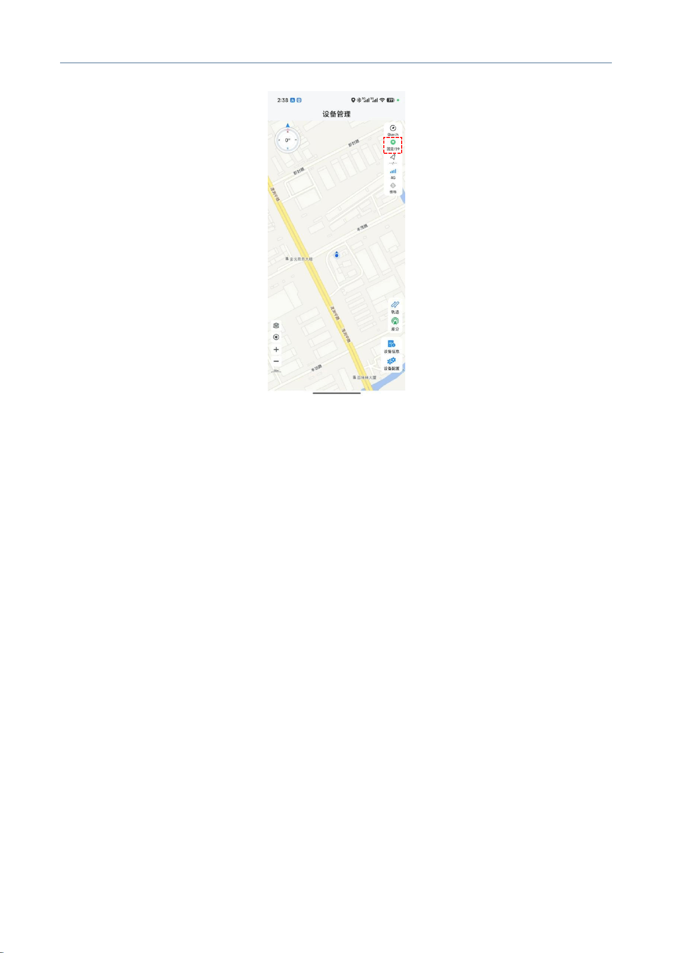
After connecting the differential data, you can use the APP to monitor the positioning status.
Check if the positioning status is Fixed Solution on the APP main interface.
M30X Integrated Navigation Receiver
Comnav Technology, LTD.
CNT-RCV-UM011, Rev 1.1
Figure. Fixed Solution
4.2.3 Wheel Speed Input
After the integrated navigation receiver is connected to vehicle wheel speed data, it can effectively
assist the system in dead reckoning under severe satellite signal occlusion or satellite signal loss, and
improve the positioning accuracy of integrated navigation in harsh satellite signal environments. The
integrated navigation system generally receives vehicle wheel speed signals via CAN / CAN FD.
Before enabling wheel speed input, please confirm that the rear axle lever arm configuration has been
completed.
Usually, the wheel speed update rate is required to be no less than 20Hz (recommended no less
than 50Hz), accuracy better than 0.1m/s (recommended better than 0.01m/s), resolution higher than
0.02m/s, and delay no more than 10ms. The device does not have a built-in terminal matching resistor,
so you need to match it at the access end when using.
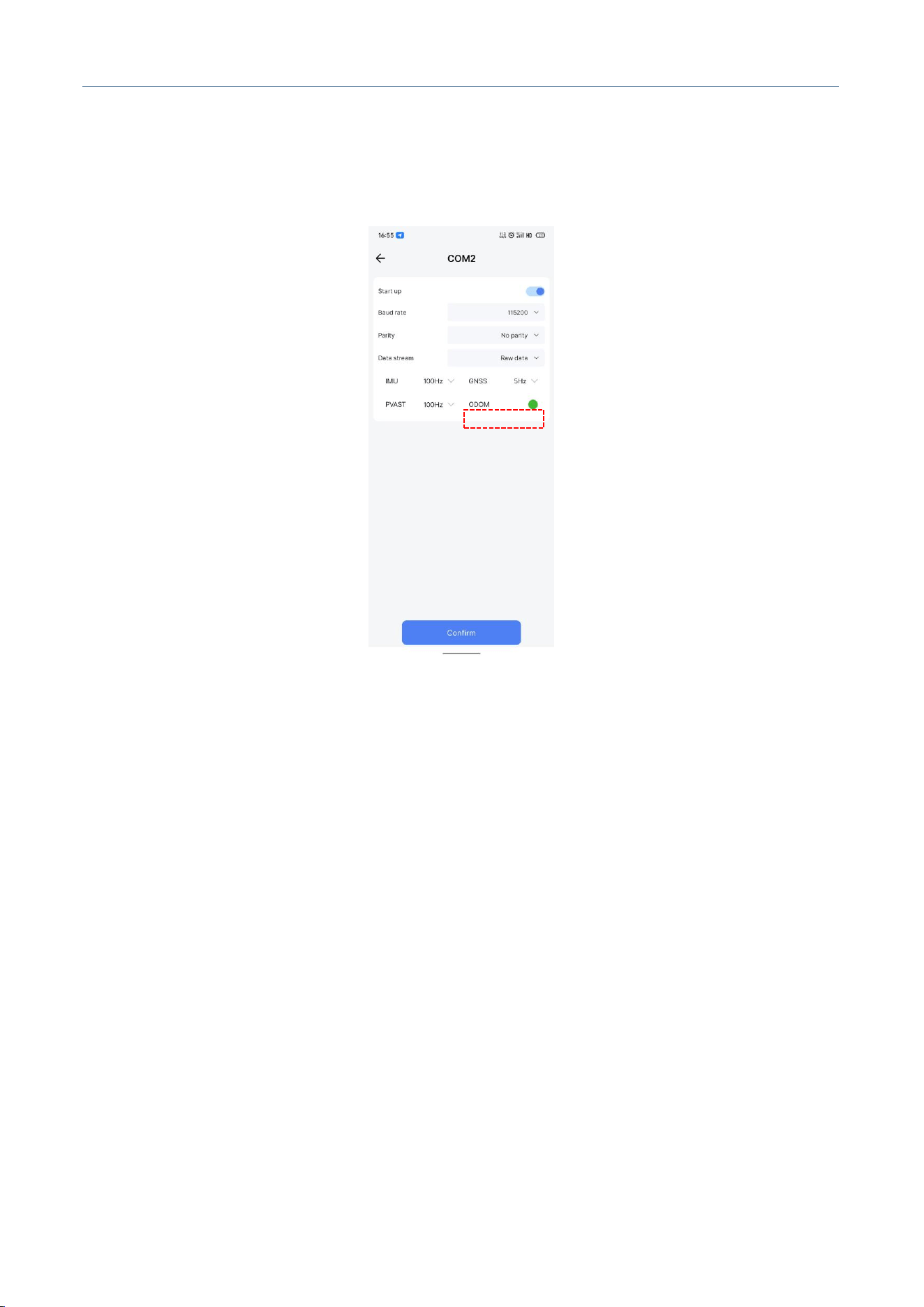
After connecting wheel speed, you can check if there is wheel speed information via the ODOM
indicator in [Data Transmission]-[Raw Data]-[Data Stream] in the APP, or use the RAWODOM
message to verify if the device has received wheel speed information. The specific method is to send
the command via serial port or Ethernet:
M30X Integrated Navigation Receiver
Comnav Technology, LTD.
CNT-RCV-UM011, Rev 1.1
LOG RAWODOMA ONNEW
If you can continuously receive RAWODOMA messages, it means the device has received the
wheel speed information.
Figure. Wheel Speed Input
4.2.4 Real-time Result Output
You can configure the device to output real-time messages via APP or serial port. Please note the
following during real-time operation:
1. Please ensure that the environment where the device is located can receive satellite signals normally.
When satellite signal is unavailable or poor, the position, velocity, and attitude information output by
the device may not meet the requirements;
2. INS navigation information and GNSS navigation information can be obtained independently.
Integrated navigation information is usually output via INS-related messages.
You can use APP or commands to configure the device to output position, attitude, and other
information. Messages can be output via network or serial port. For APP configuration operations,
please refer to Section 4.1.8 and 4.1.9.
M30X Integrated Navigation Receiver
Comnav Technology, LTD.
CNT-RCV-UM011, Rev 1.1
For serial command configuration, take the INSPVA message printing as an example. The
command to print 100Hz INSPVA message in ASCII format is as follows:
LOG INSPVAA ONTIME 0.01
When outputting INS-related messages at high frequency, the data volume is large. To ensure
data integrity, it is recommended to use Ethernet to transmit binary messages. If using serial port
transmission, it is recommended to set the serial baud rate to 921600.
Common integrated navigation messages are shown in Table 3:
Table 3. Integrated Navigation Related Messages
Classify
Related Information
Position
INSPOS、INSPVA、INSPVAX
Velocity
INSVEL、INSSPD、INSPVA、INSPVAX
Attitude
INSATT、INSPVA、INSPVAX
Calculation Reliability
INSSTDEV、INSPVAX
4.2.5 System Alignment
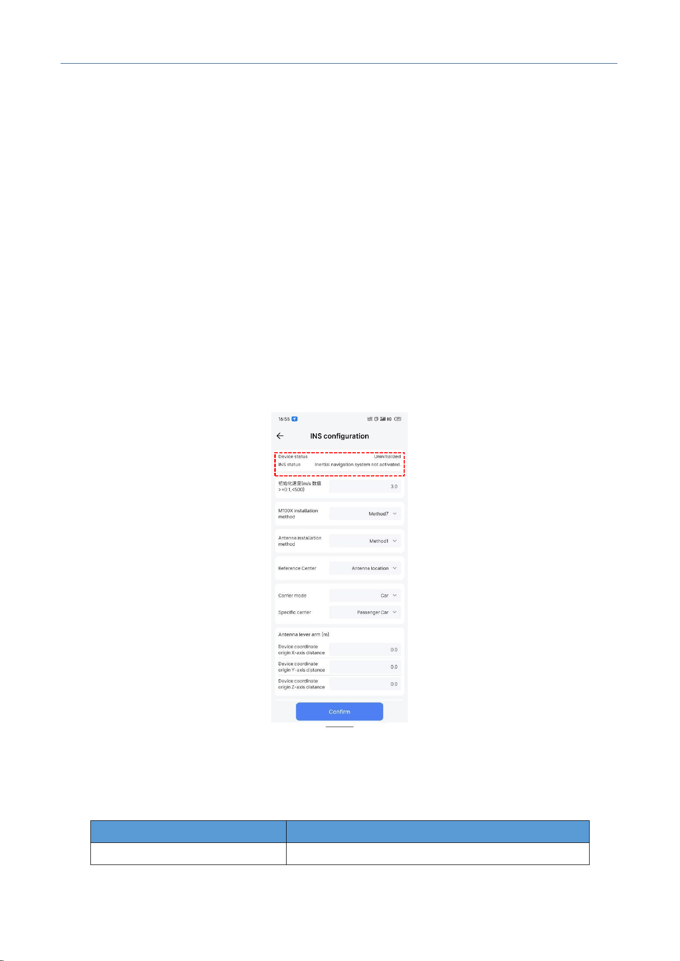
System alignment is the process where the integrated navigation system obtains the current
position, velocity, and attitude information to complete system initialization. You can confirm the
system alignment progress in real time via the INS status display in the APP, or the Status field in the
INSPVA/INSPVAX message.
After the M30X is powered on, the device will perform alignment according to the following
process:
1. Device powered on, the system is in INACTIVE state, the INS system is inactive. At this time, the
APP displays Uninitialized, and the INS system is aligning;
2. When the satellite signal is good, the device will enter alignment mode, the status switches to
ALIGNING, and the INS system is aligning. In alignment mode, the device will determine the initial
position, velocity, and heading of the carrier based on GNSS data. At this time, the APP displays
Uninitialized, and the INS system is aligning;
3. If the device is connected with dual antennas and the dual antenna installation angle is configured
correctly, system alignment can be completed in static state. If there is no dual antenna access or the
M30X Integrated Navigation Receiver
Comnav Technology, LTD.
CNT-RCV-UM011, Rev 1.1
dual antenna observation quality is poor, you need to drive straight for a period of time with a speed
meeting the threshold to complete system alignment, the default threshold is 3m/s;
4. After system alignment is complete, the status switches to ALIGNMENT_COMPLETE, the INS
alignment is complete. At this time, the APP displays Alignment complete, but insufficient vehicle
dynamics, calibration not complete;
5. The device continues to correct the integrated navigation results via GNSS data. After the carrier
performs certain turning maneuvers, the accuracy converges successfully. At this time, the status
switches to SOLUTION_GOOD, which means the integrated navigation accuracy is high. At this
time, the APP displays Initialization successful, navigation accuracy is high;
6. When the error of the integrated navigation system is large, the device will switch to
HIGH_VARIANCE state. When the GNSS navigation result is unavailable, it will switch to
SOLUTION_FREE state. Table 4 summarizes and briefly describes the above states.
Figure. INS Status Display
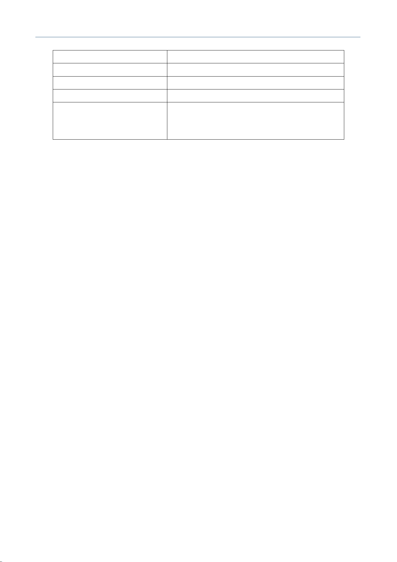
Table 4. Inertial Navigation Status
State Identifier
Describe
INACTIVE
INS is inactive
M30X Integrated Navigation Receiver
Comnav Technology, LTD.
CNT-RCV-UM011, Rev 1.1
ALIGNING
ALIGNING INS is in alignment mode
HIGH_VARIANCE
INS solution may not meet accuracy specifications
SOLUTION_GOOD
INS is in navigation mode with high accuracy
SOLUTION_FREE
INS filter is in navigation mode, but GNSS is unavailable
ANLIGNMENT_COMPLETE
INS filter is in navigation mode, but vehicle dynamics are
insufficient and the system does not meet accuracy
specifications
4.2.6 Online Calibration
After the initial installation and configuration of the device rotation parameters / GNSS antenna
lever arm / dual antenna installation angle parameters, you can use the online calibration function to
estimate more accurate parameters, improving the accuracy of the integrated navigation results.
The online calibration parameters are: 1. Device rotation parameters; 2. GNSS antenna lever arm
parameters; 3. Dual antenna installation angle parameters.
The online calibration process is as follows:
1. Power on the device, send the command to clear calibration parameters, clear the original
parameters:
CLEARDRCLBPARAM
2. Send the device restart command RESET, wait for the device to restart;
3. Complete system alignment;
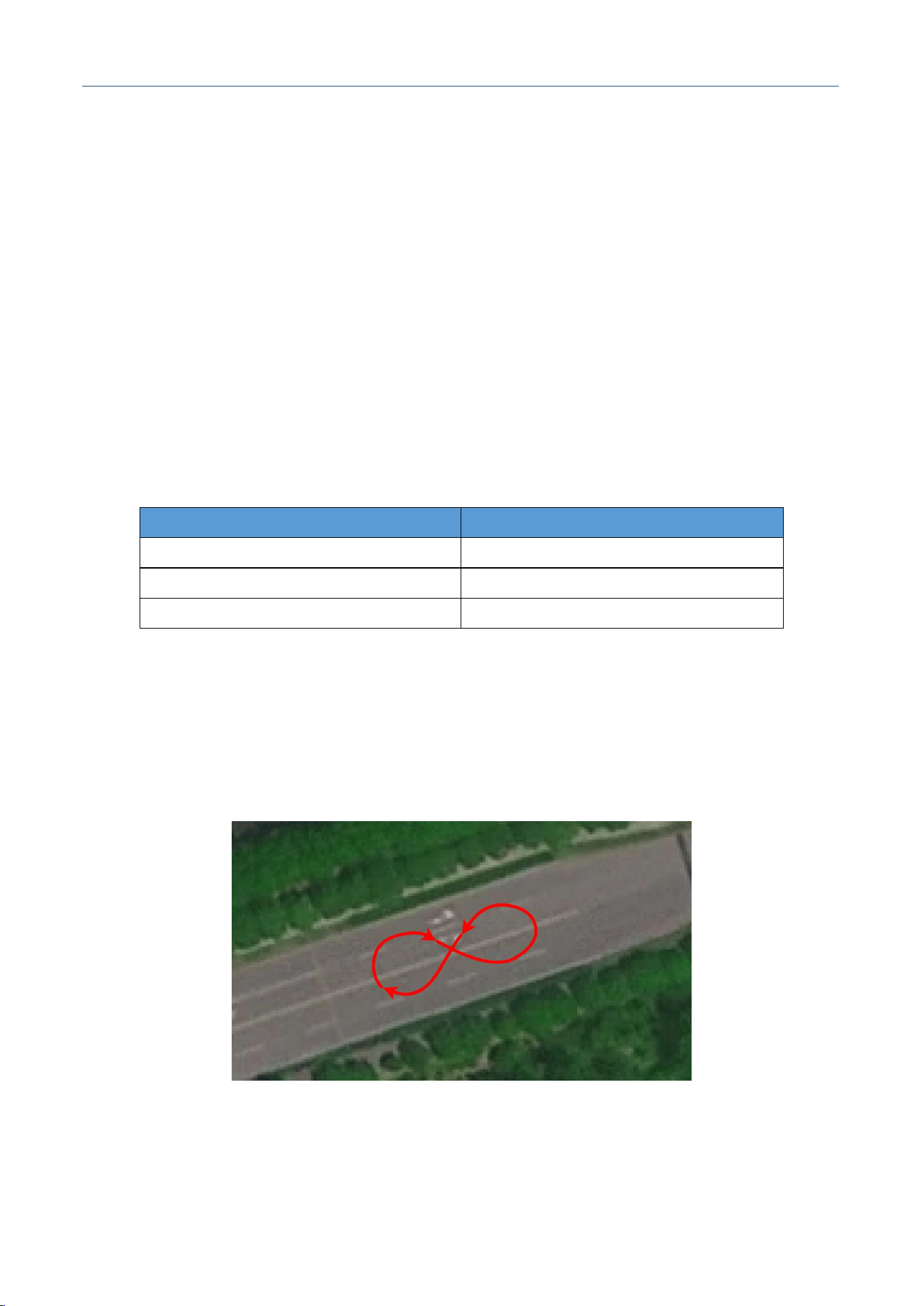
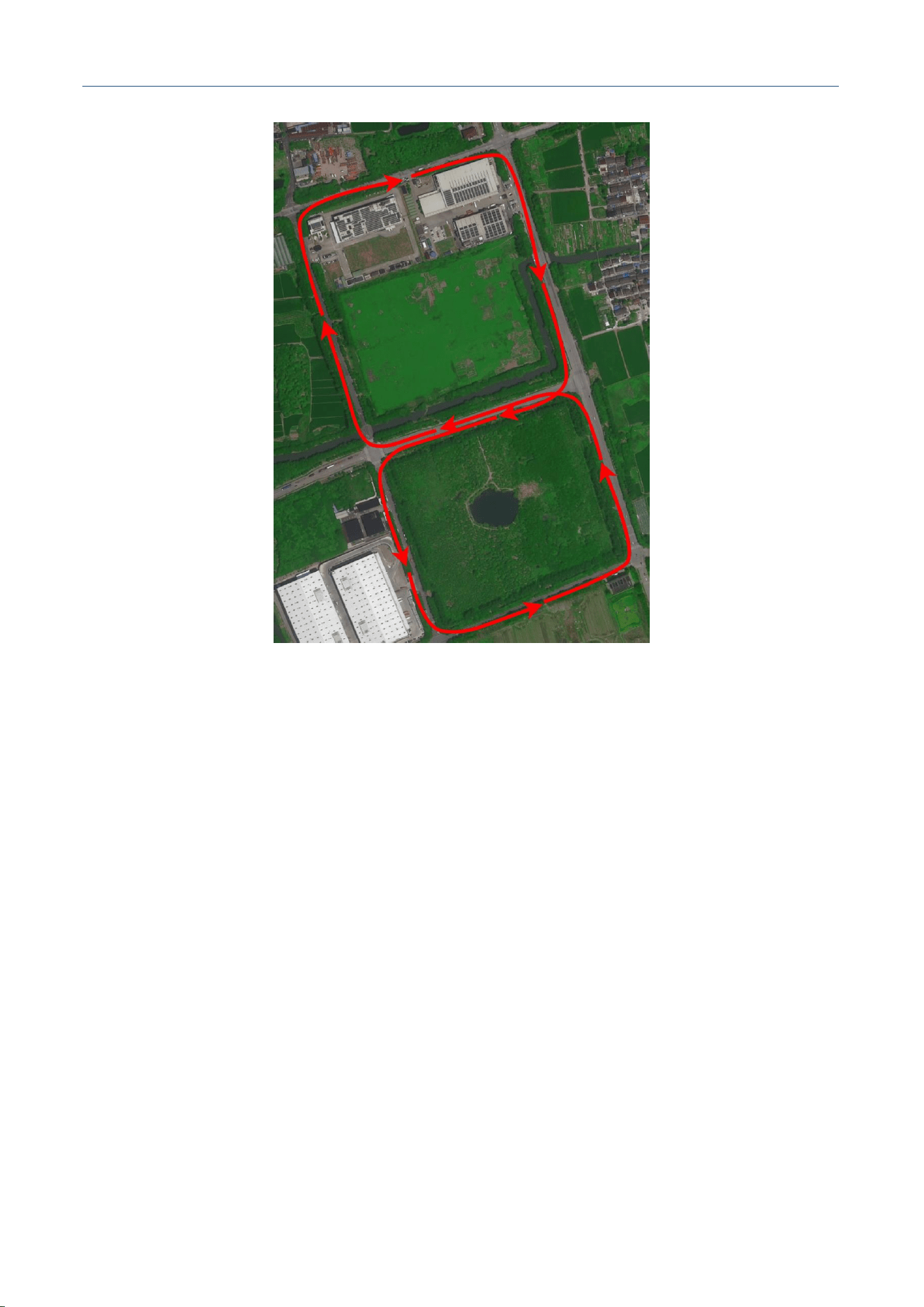
4. Drive the vehicle at a certain speed (recommended above 5m/s, no less than 1m/s) for about 5
minutes. The recommended route is shown in the figure; if you cannot use the figure-8 route, you
need to ensure that during the online calibration, the vehicle's driving status includes straight driving
and turning, such as driving in a daily shape along urban roads;
5. You can enable/disable the online calibration status message printing via LOG/UNLOG commands:
LOG INSCALIBSTATE ONTIME 1
UNLOG INSCALIBSTATE
6. After the command is issued, the serial port will continuously send messages containing the
online parameter calibration status and estimated values. These messages only reflect the
M30X Integrated Navigation Receiver
Comnav Technology, LTD.
CNT-RCV-UM011, Rev 1.1
current calibration status, and previous calibration statuses cannot be viewed. The message
format is as follows:
%INSCALIBSTATES,WEEK,GPST;GPST,STATE,LeverArmX,LeverArmY,LeverArmZ,Mis
AngleX,MisAngleY,MisAngleZ,HeadingDiff;
Where, the STATE field represents the current online calibration status. The status of each
calibration parameter is shown in Table 5. When the corresponding parameter calibration is complete,
the STATE parameter will add the corresponding calibration status. For example, when the antenna
lever arm, device installation angle, and dual antenna installation angle are all calibrated, the STATE
field is 0x07.
Table 5. Calibration Parameter Status Information
Calibration Parameters
**Calibration Completion Status**
Antenna Lever Arm
0x01
Device Mounting Angle
0x02
Dual Antenna Installation Angle
0x04
7. Each time the device is powered on, it will read the calibration status and parameters. If the
corresponding parameters are calibrated, it will automatically configure the calibrated parameters;
8. If you want to view the previous calibration status of the device, you can send the
READDRCLBPARAM command to query.
Figure. Recommended Route 1 for Online Calibration
M30X Integrated Navigation Receiver
Comnav Technology, LTD.
CNT-RCV-UM011, Rev 1.1
Figure. Recommended Route 2 for Online Calibration
4.2.7 Data Post-processing
The raw data output by the M30X can be post-processed with professional software. The post-
processing software can obtain more accurate positioning results after the fact through bidirectional
solution and smoothing, which can be used as a test benchmark.
4.2.8 Firmware Upgrade
The device can be upgraded via serial port or remote NavCloud.
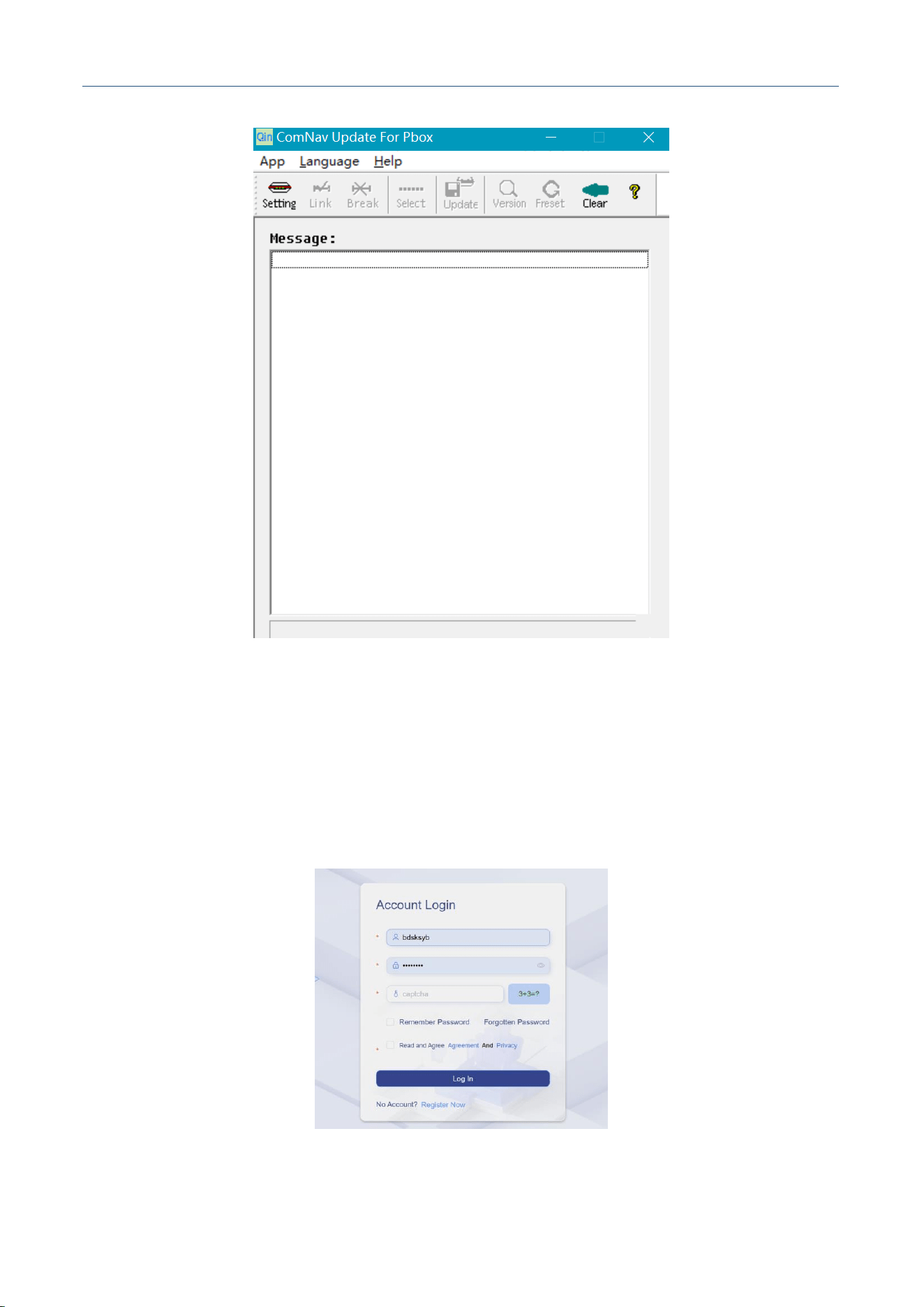
1. Serial Upgrade: Power on the receiver, connect COM2 via serial port, open the serial upgrade tool
QinT_Pbox_Update.exe, click Setting, select the identified port number, click Link to connect the port.
Normally, the serial port will print the information of the device's current version. Click Select to
select the firmware BIN file, click Update to start the upgrade. Wait for about 20s after starting the
upgrade, the progress bar will start to move.
M30X Integrated Navigation Receiver
Comnav Technology, LTD.
CNT-RCV-UM011, Rev 1.1
Figure. Serial Upgrade Tool
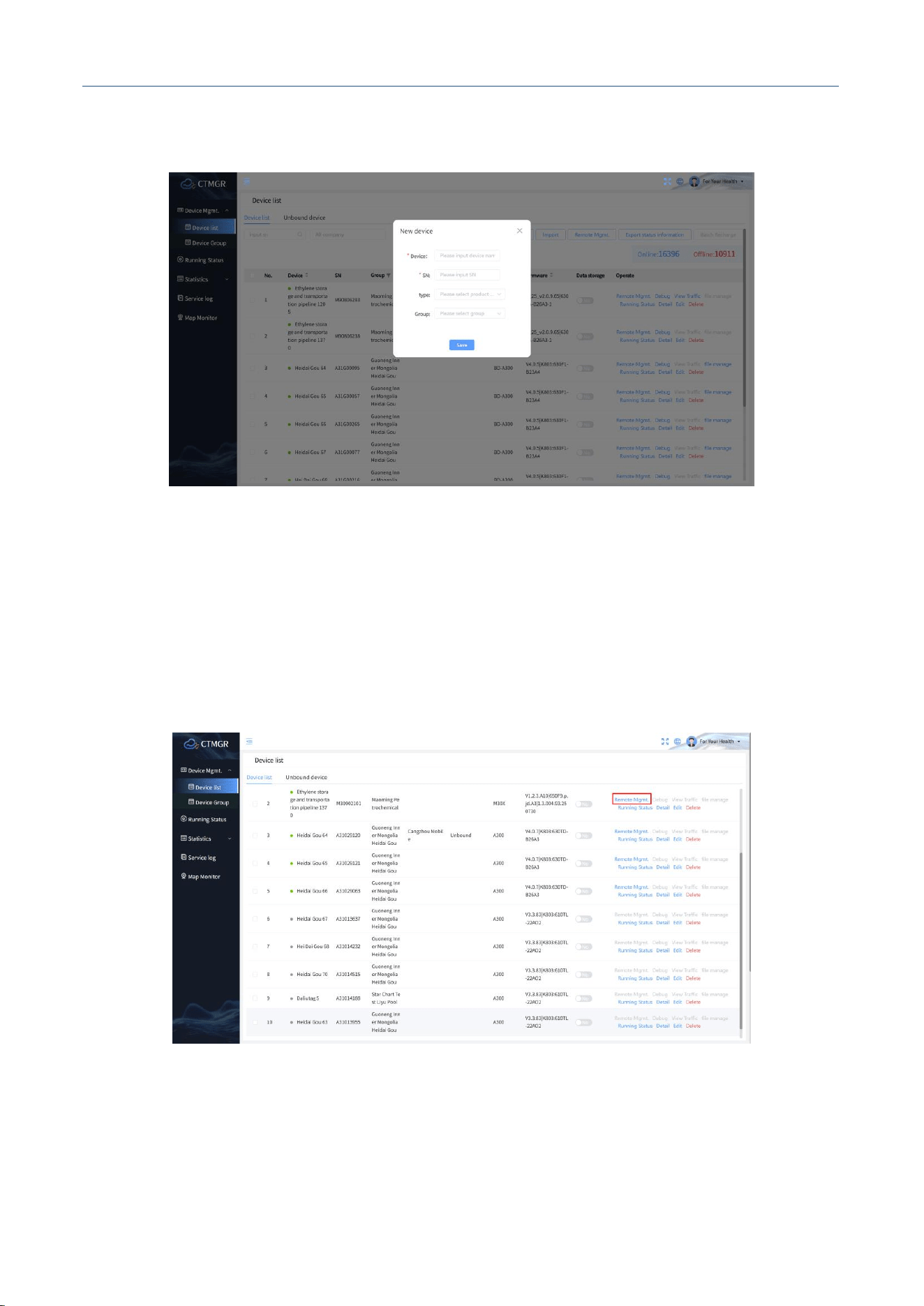
2. Remote Upgrade: The M30X supports remote upgrade, you need to log in to the ComNav NavCloud
platform to operate. Before remote upgrade, please ensure that [Data Transmission]-[NavCloud] is
enabled, and the device is connected via 4G or network.
① Log in to NavCloud: Login address: , enter your account and password.
Figure. Log in to NavCloud Platform
M30X Integrated Navigation Receiver
Comnav Technology, LTD.
CNT-RCV-UM011, Rev 1.1
② Create Device: Click [Create Device], enter the device name and SN, click [Save].
Figure. Create Device
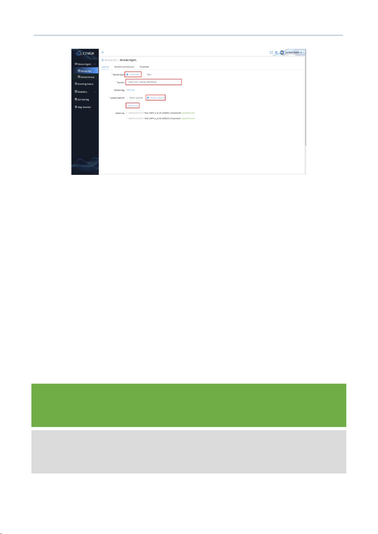
③ Remote Management: After creating the device, if the device communication is normal, it will
show online. Click [Remote Management], select [Online Upgrade], select the corresponding
version type (Official / Beta), firmware version, upgrade method (Board Upgrade / System
Upgrade), click [Upgrade Now].
M30X Integrated Navigation Receiver
Comnav Technology, LTD.
CNT-RCV-UM011, Rev 1.1
Figure. Remote Upgrade
5 APPENDIX B COMMON COORDINATE SYSTEM
DESCRIPTION
5.1 DEFINITION OF COMMON COORDINATE SYSTEMS IN
INTEGRATED NAVIGATION SYSTEM
M30X Integrated Navigation Receiver
Comnav Technology, LTD.
CNT-RCV-UM011, Rev 1.1
In the integrated navigation system, commonly used coordinate systems include the local
navigation coordinate system, body coordinate system, vehicle coordinate system and user-defined
coordinate system.
5.1.1 Local Navigation Coordinate System
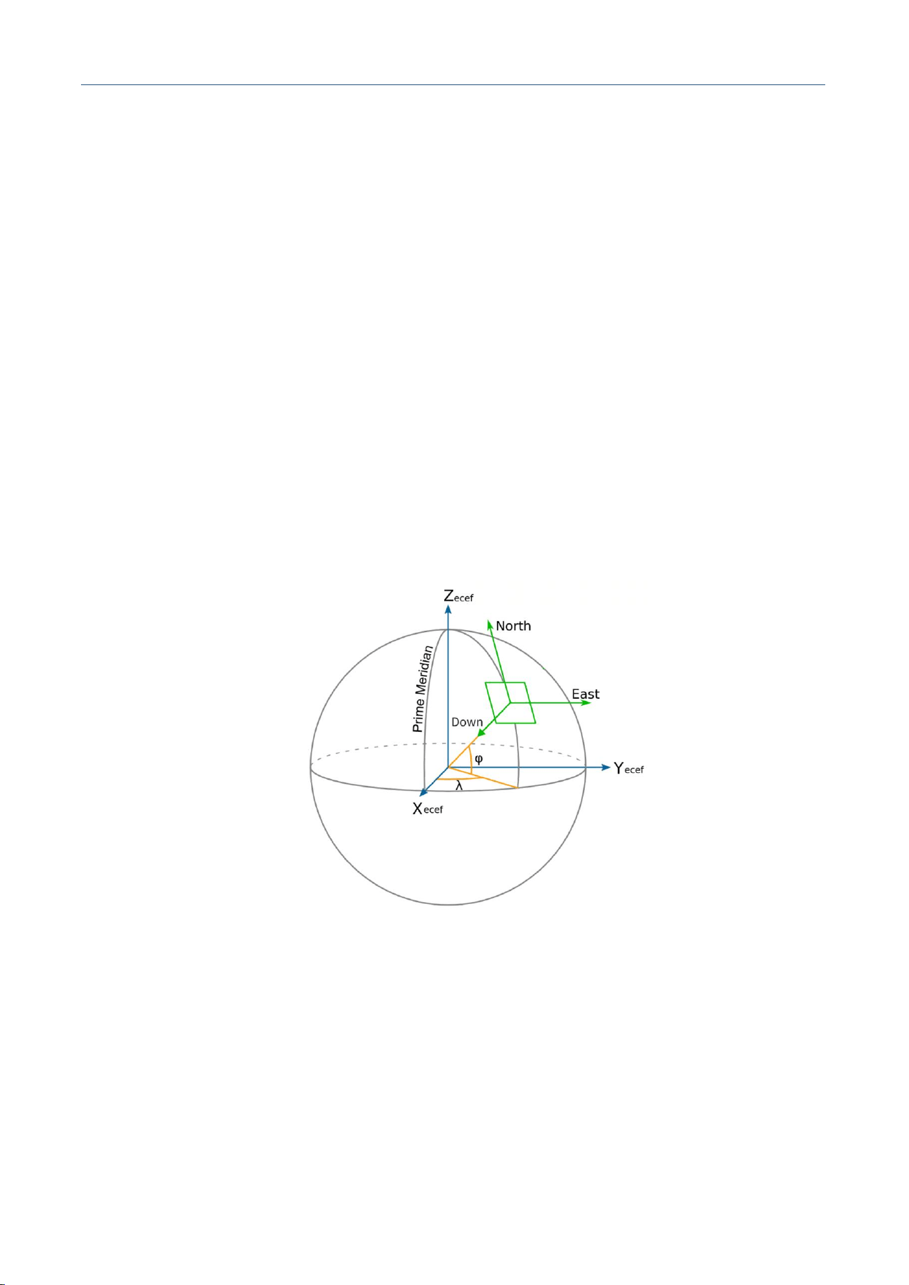
The local navigation coordinate system, also known as N-E-D (North-East-Down) coordinate
system, is defined as follows:
N-axis: Points to the North (in the plane perpendicular to the D-axis, the direction from the user
to the North Pole)
E-axis: Points to the East (the right-handed orthogonal axis derived from N-axis and D-axis)
D-axis: Points Down (the normal direction of the reference ellipsoid)
The origin of the local navigation coordinate system is the navigation center marked on the device
housing.
Figure. Local Navigation Coordinate System
5.1.2 Device Coordinate System
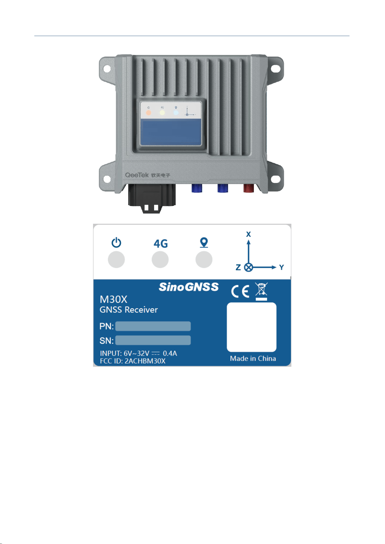
The origin and axes of the device coordinate system are marked on the device housing, the
navigation center is the origin of the coordinate system.
M30X Integrated Navigation Receiver
Comnav Technology, LTD.
CNT-RCV-UM011, Rev 1.1
Figure. Device Coordinate System
5.1.3 Vehicle Coordinate System
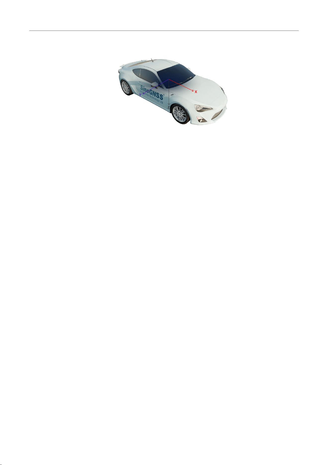
The origin of the vehicle coordinate system is the navigation center marked on the device housing.
M30X Integrated Navigation Receiver
Comnav Technology, LTD.
CNT-RCV-UM011, Rev 1.1
Figure. Vehicle Coordinate System
The axes of the vehicle coordinate system are defined as follows:
Z-axis: Perpendicular to the vehicle floor, pointing to the bottom of the vehicle
X-axis: Points to the forward direction of the vehicle
Y-axis: The right-handed orthogonal axis derived from X-axis and Z-axis
If you use the land vehicle model, please configure the antenna lever arm and rotation parameters
strictly according to this vehicle coordinate system.
5.1.4 User-defined Coordinate System
The right-handed coordinate system with origin and axes specified by the user is called the user-
defined coordinate system. By default, the device outputs the position and velocity information of the
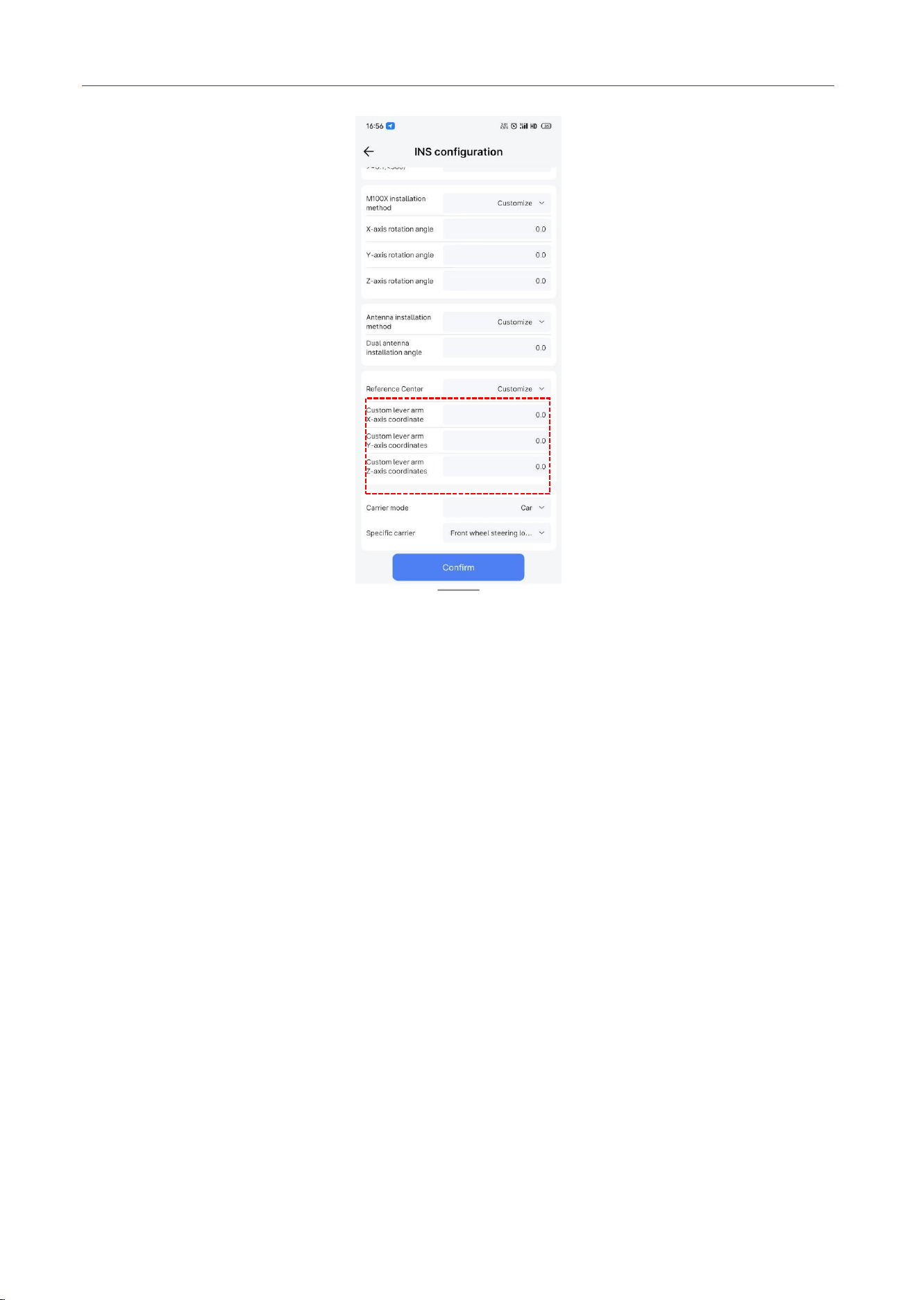
device navigation center (the origin of the device coordinate system). You can use the APP to set
[Reference Center], select [Custom] to enter custom XYZ coordinates, and set the coordinate system
origin to any point.
M30X Integrated Navigation Receiver
Comnav Technology, LTD.
CNT-RCV-UM011, Rev 1.1
Figure. User-defined Coordinate System

M30X Integrated Navigation Receiver
Comnav Technology, LTD.
CNT-RCV-UM011, Rev 1.1
6 TROUBLESHOOTING
If you encounter the problems listed in this section when using the M30X integrated navigation
receiver, troubleshoot them according to the following methods. If the issue cannot be resolved, please
contact our technical support personnel in a timely manner.
1. Device fails to power on
Solutions:
1) Check if the power voltage is normal. If the power supply is faulty, power off, replace it with
a normal power supply before using the product;
2) Check if the power cable connection is correct and secure;
3) Use a multimeter to measure the connector voltage, check if the connection cable is intact. If
the cable is faulty, replace it.
4) If the above causes are excluded, the device may be damaged. Please contact our technical
support.
2. No Serial Response
Solutions:
1) Check if the serial port number and baud rate are correct. Please read the communication
protocol carefully to ensure correct configuration of the serial port;
2) Check if the data cable is damaged;
3) Check if the serial port driver is installed;
4) Check if the data cable is connected securely.
3. Abnormal Positioning
Solutions:
1) Check if the receiver is obstructed;
2) Check if the connectivity of the communication system is reliable;
3) Check if there is RF interference on the GNSS antenna frequency;
4) Confirm if the INS initialization is successful;

M30X Integrated Navigation Receiver
Comnav Technology, LTD.
CNT-RCV-UM011, Rev 1.1
5) Confirm if the base station coordinates have too large deviation from the real coordinates.
4. 4G Disconnection
Solutions:
1) Confirm if the 4G SIM card is overdue;
2) Confirm if the device power supply is normal;
3) If the operator's network is unstable in this area, please replace the 4G SIM card of another
operator.
7 PRECAUTIONS
1. It is strictly prohibited to disassemble any parts of the system device. If a fault occurs, please
record the relevant situation and contact our technical support staff in time;
2. Pay attention to the working voltage of each device. Please use the standard power adapter
and data cable provided by our company to avoid damage to the device;
3. When connecting the power cable, do not reverse the polarity of the power supply;
4. Please connect the devices strictly according to the installation and wiring methods in the
manual, make sure all connectors are plugged in tightly;
5. Do not continue to use damaged cables or accessories, please replace them with new ones in
time to avoid unnecessary injury.

ComNav Technology Ltd.
CNT-SW-RM001, Rev 1.4
66
Comnav Technology, LTD.
Building 2, 618 Chengliu Middle Road, Jiading District, Shanghai
Website:https://www.comnavtech.com/
Tel:+86 21 64056796
FCC Statement
Any Changes or modifications not expressly approved by the party responsible for compliance could void the
user's authority to operate the equipment.
This device complies with part 15 of the FCC Rules. Operation is subject to the following two conditions:
(1) This device may not cause harmful interferenc
(2) This device must accept any interference received, including interference that may cause unde operation.
Note : This equipment has been tested and found to comply with the limits for a Class B digital device,
pursuant to part 15 of the FCC Rules. These limits are designed to provide reasonable protection against
harmful interference in a residential installation. This equipment generates,uses and can radiate radio
frequency energy and, if not installed and used in accordance with the instructions, may cause harmful
interference to radio communications. However, there is no guarantee that interference will not occur in a
particular installation. If this equipment does cause harmful interference to radio or television reception, which
can be determined by turning the equipment off and on, the user is encouraged to try to correct the
interference by one or more of the following measures:
—Reorient or relocate the receiving antenna.
—Increase the separation between the equipment and receiver.
—Connect the equipment into an outlet on a circuit different from that to which the receiver is connected.
—Consult the dealer or an experienced radio/TV technician for help.
FCC Radiation Exposure Statement:
This equipment complies with FCC radiation exposure limits set forth for an uncontrolled environment .This
equipment should be installed and operated with minimum distance 20cm between the radiator& your body.