Datasheet
Dräger BT-modules – 11384050
Confidential Information. Property of Dräger Safety AG & Co. KGaA. All
rights reserved.
To be passed on only after written consent by Dräger Safety AG & Co.
KGaA.
Printed versions are uncontrolled
1 / 31
Dräger Bluetooth Platform
Dräger BT-modules
BT-03
Datasheet
Revision: 01
State: released
Copyright
Dräger Safety AG & Co. KGaA
Author:
D.Gerlach, P.Christmann
Verified by
Dept.: 5430
Signature:
Dept.: 5465
Signature:
Name: P. Christmann
Name: Jasser Rahmatyan
Phone: 1684
Phone: 6186
Date:
Date:
Datasheet
Dräger BT-modules – 11384050
Confidential Information. Property of Dräger Safety AG & Co. KGaA. All
rights reserved.
To be passed on only after written consent by Dräger Safety AG & Co.
KGaA.
Printed versions are uncontrolled
2 / 31
Document Information
Changelog of Document
Revision
State
Date
Author / Editor
Reason of Adaption
00
Initial
P. Christmann
initial document derived from BT-01&BT-02
datasheet (Doc. No. 11110099 01)
01
Released
2026-04-01
P. Christmann
- Added 7 Design Checklist
- Changed 3.3 Port Functions and Pin
Assignment List:
o Add standard configuration for
UART pins
o Clarified Port pins without
physical module pin assigned
- Changed 2.1.3.1 Bluetooth
Communication Interface
- Added document reference for 4.3.7
BT03 Radiation patterns
- Reworked BT03 Approvals

Datasheet
Dräger BT-modules – 11384050
Confidential Information. Property of Dräger Safety AG & Co. KGaA. All
rights reserved.
To be passed on only after written consent by Dräger Safety AG & Co.
KGaA.
Printed versions are uncontrolled
3 / 31
Table of Content
DOCUMENT INFORMATION .............................................................................................. 2
1 PRODUCT OVERVIEW ................................................................................................. 6
1.1 Functional description ...................................................................................................................................... 6
1.2 Hardware description ....................................................................................................................................... 6
1.2.1 BT03 (9 x 11 mm) ....................................................................................................................................... 6
1.3 Software architecture ........................................................................................................................................ 7
1.3.1 nRF Connect SDK ....................................................................................................................................... 7
1.3.2 Zephyr OS ................................................................................................................................................... 7
1.3.3 Dräger BLE platform core ........................................................................................................................... 8
1.3.4 Product specific service extensions ............................................................................................................. 8
1.3.5 Bootloader ................................................................................................................................................... 8
1.3.6 DTM-Firmware ........................................................................................................................................... 8
1.4 Example applications ........................................................................................................................................ 8
2 SYSTEM FEATURES.................................................................................................. 10
2.1.1 Power Management ................................................................................................................................... 10
2.1.2 Reset Functionality .................................................................................................................................... 10
2.1.3 RF Antenna Interfaces ............................................................................................................................... 10
2.1.3.1 Bluetooth Communication Interface ..................................................................................................... 10
2.1.3.2 NFC Integration .................................................................................................................................... 10
2.1.4 Clock Accuracy ......................................................................................................................................... 10
2.1.4.1 Low frequency clock ............................................................................................................................. 10
2.1.4.2 High frequency clock ............................................................................................................................ 10
2.1.5 Flexible Interface Options ......................................................................................................................... 10
3 PACKAGE AND PINNING DEFINITIONS .................................................................. 11
3.1 BT03 – 9x11 mm Package ............................................................................................................................... 11
3.2 Library Part and Footprint ............................................................................................................................ 11
3.3 Port Functions and Pin Assignment List ....................................................................................................... 11

Datasheet
Dräger BT-modules – 11384050
Confidential Information. Property of Dräger Safety AG & Co. KGaA. All
rights reserved.
To be passed on only after written consent by Dräger Safety AG & Co.
KGaA.
Printed versions are uncontrolled
4 / 31
4 ELECTRICAL SPECIFICATIONS ............................................................................... 14
4.1 Absolute maximum ratings ............................................................................................................................ 14
4.2 Maximum ESD ratings ................................................................................................................................... 14
4.3 Recommended operating conditions .............................................................................................................. 14
4.3.1 Current consumption ................................................................................................................................. 15
4.3.2 RF-Performance ........................................................................................................................................ 16
4.3.2.1 Receiver Sensitivity............................................................................................................................... 16
4.3.2.2 Transmit Power ..................................................................................................................................... 16
4.3.3 Startup times.............................................................................................................................................. 16
4.3.4 LFXO crystal specifications ...................................................................................................................... 17
4.3.5 nRESET pin .............................................................................................................................................. 17
4.3.6 Digital pins ................................................................................................................................................ 17
4.3.7 BT03 Radiation patterns ............................................................................................................................ 17
5 EXPLORATION TESTS .............................................................................................. 18
5.1 Data Throughput ............................................................................................................................................. 18
5.1.1 Buffer configuration .................................................................................................................................. 18
5.1.2 Peripheral Latency .................................................................................................................................... 18
5.1.3 Payload size of packages to transmit via BLE .......................................................................................... 19
5.1.4 Connection Interval ................................................................................................................................... 19
5.1.4.1 Throughput with payload chunks of 1024 bytes ................................................................................... 20
5.1.4.2 Throughput with payload chunks of 32 bytes ....................................................................................... 21
6 MECHANICAL SPECIFICATIONS ............................................................................. 22
6.1 Maximum height BT03 ................................................................................................................................... 22
7 DESIGN CHECKLIST ................................................................................................. 23
7.1 UART Interface ............................................................................................................................................... 23
7.2 External capacitors ......................................................................................................................................... 23
7.3 RESET circuit ................................................................................................................................................. 23
8 LIMITATIONS .............................................................................................................. 24

Datasheet
Dräger BT-modules – 11384050
Confidential Information. Property of Dräger Safety AG & Co. KGaA. All
rights reserved.
To be passed on only after written consent by Dräger Safety AG & Co.
KGaA.
Printed versions are uncontrolled
5 / 31
8.1 No compliance for Safety Integrity Level (SiL) applications....................................................................... 24
8.2 Setting of maximal transmitting radio output power................................................................................... 24
9 SOLDERING PROFILE ............................................................................................... 25
10 APPROVALS .............................................................................................................. 26
10.1 Approval information in production ............................................................................................................. 26
10.1.1 Due to small size of the modules, it is not possible to laser all approval information for all countries on the
shield can for BT03. Therefore, an external shield can label was created and an approval label for the package was
created. 26
10.1.2 Package approval label BT03 .................................................................................................................... 26
10.2 Federal Communicators Commissions for US (FCC) .................................................................................. 26
10.2.1 List of approved Antennas for BT03 ......................................................................................................... 27
10.2.2 FCC ID BT03 ............................................................................................................................................ 27
10.3 Innovation, Science, and Economic Development (ISED) for Canada ....................................................... 27
10.3.1 List of approved Antennas ........................................................................................................................ 28
10.3.2 License ID BT03 ....................................................................................................................................... 28
10.4 KC Certification for BT03 .............................................................................................................................. 28
10.4.1 KC Certification BT03 .............................................................................................................................. 28
10.4.2 KC Mark BT03 ......................................................................................................................................... 28
10.5 JP Certification for BT03 ............................................................................................................................... 28
10.5.1 JP Certification BT03 ................................................................................................................................ 28
10.5.2 JP Mark BT03 ........................................................................................................................................... 28
10.6 European Conformity According to RED (2014/53/EU) ............................................................................. 29
10.7 Bluetooth SIG .................................................................................................................................................. 29
11 GLOSSARY ................................................................................................................ 30
11.1 Abbreviation & Acronyms ............................................................................................................................. 30
11.2 References ........................................................................................................................................................ 31
Datasheet
Dräger BT-modules – 11384050
Confidential Information. Property of Dräger Safety AG & Co. KGaA. All
rights reserved.
To be passed on only after written consent by Dräger Safety AG & Co.
KGaA.
Printed versions are uncontrolled
6 / 31
1 Product Overview
1.1 Functional description
Primary intended purpose of the Dräger BT-modules is to provide Bluetooth 5.1 low energy communication
capability to Dräger products by populating a Dräger BT-module at production lines on product PCB’s and
flashing an appropriate BLE-firmware to the module.
Technical use case of the BT-module is to operate as a communication gateway between the product MCU
wired to a serial UART port and a peer device connected via Bluetooth low energy (BLE).
The Dräger BT-module hardware is based on the Nordic Semiconductor nRF52840 chip that includes an
integrated 2.4 GHz transceiver with +8 dBm output power and powerful Arm® Cortex®-M4 with FPU processor.
The BT-modules usage is supported by Dräger BLE-platform firmware, which provides a set of defined
services to configure BLE-settings, control of BLE-connections to peer devices and to transmit / receive
payload associated with established BLE-connections. The services can be accessed from products by
defined service messages on the UART-interface.
For universal and transparent gateway communication of any content, the Dräger GATT UART Service is
provided, which can be accessed by the “Passthrough” service from the UART-interface and by the GATT
Service from connected BLE-peers.
For products, which need to communicate with specific GATT services given by existing peer devices, the
BLE platform firmware architecture supports optional extension of GATT-service integrations and
corresponding service handlers for routing the content to corresponding service-messages on the UART-
interface.
Furthermore, the Dräger BT-modules are designed to fulfill the ATEX, IECEx requirements.
1.2 Hardware description
1.2.1 BT03 (9 x 11 mm)
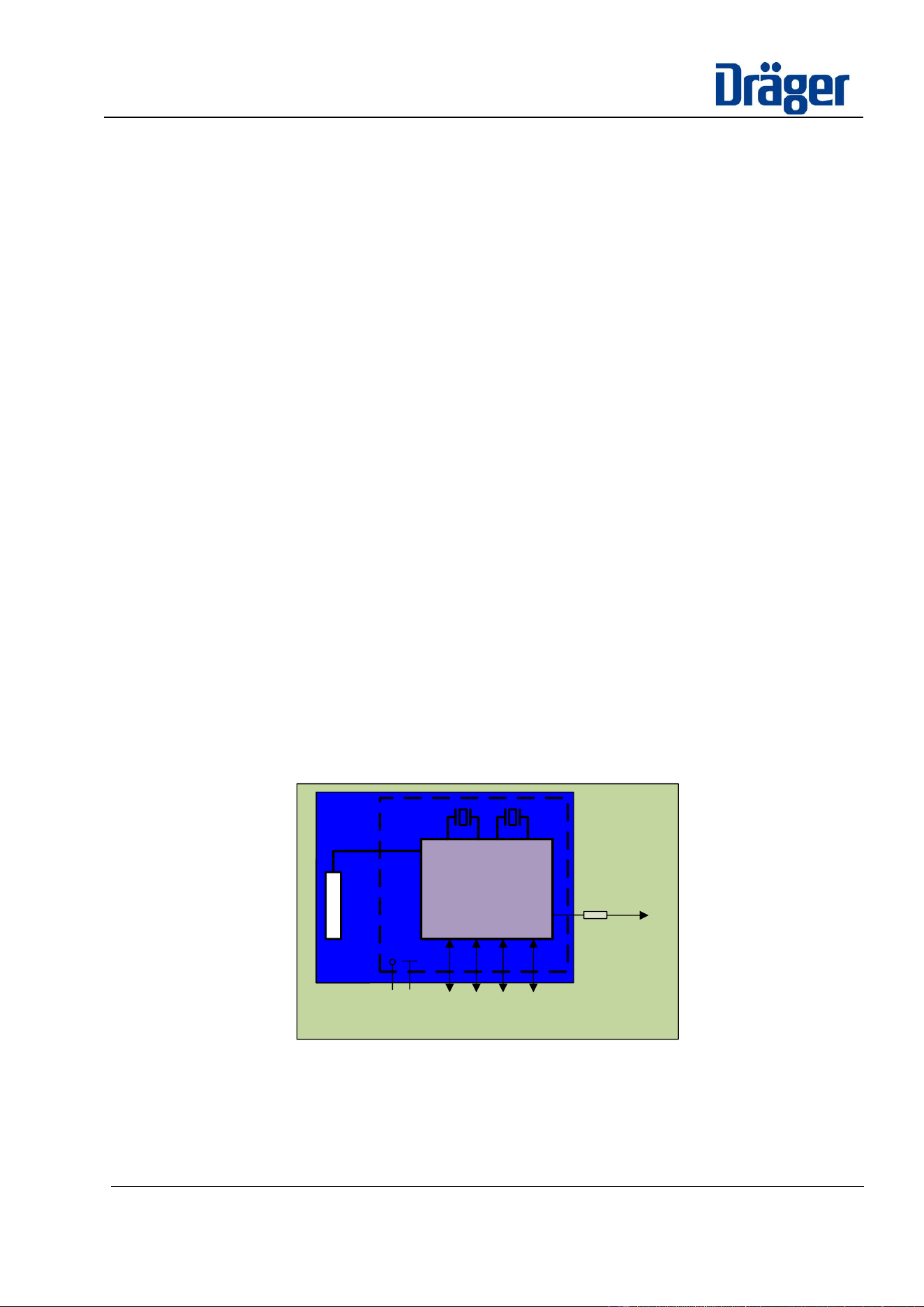
The Dräger module contains the nRF52840 Chipset from Nordic Semiconductor. Due to space requirements a
small footprint ceramic loop antenna is used. Note that in this variant there is no option to use an external
antenna. In addition to that, a low frequency crystal (32,768 kHz) is placed on the module.
Nordic
nRF52840
Antenna
VDD
GND
SPI
Uart
NFC
Debug/
Programm
32kHz
32MHz
Reset
Figure 1.2-1:Block Diagram Dräger BT Modul 9x11mm
Key features are:
- small size 11x9mm
- BT 5.3 functionality (long range capable, direction finding, support of mesh networks)
Datasheet
Dräger BT-modules – 11384050
Confidential Information. Property of Dräger Safety AG & Co. KGaA. All
rights reserved.
To be passed on only after written consent by Dräger Safety AG & Co.
KGaA.
Printed versions are uncontrolled
7 / 31
- easy to integrate in EX protected devices in terms of having no inductors and a reduced value of
capacitance
- support of low energy applications
1.3 Software architecture
The software designed for the Dräger BT-modules is dedicated to being flashed and process on the nRF52840
ARM-Cortex 4 chips from Nordic, which is populated on the BT-module. In general, the BT-modules in
conjunction with the Dräger BLE-Firmware operate as a communication gateway for Dräger products. The
product application firmware controls and communicates to the BT-module via service-messages on a serial
UART-line - the BLE-firmware transfers the communication-payload to GATT-communication services
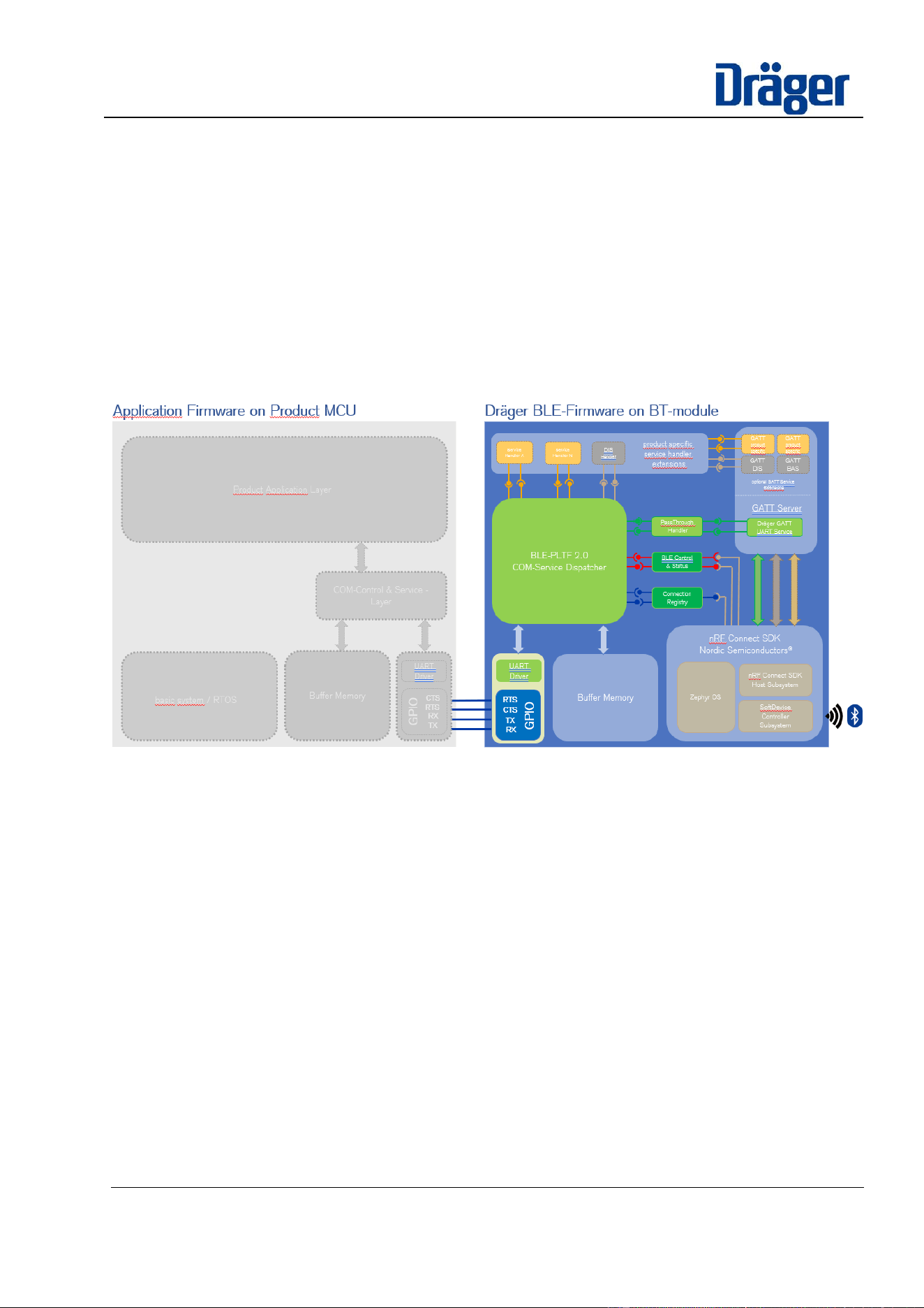
associated to the BLE-stack. The BLE-Firmware is based on a Dräger BLE software platform core and optional
product specific extensions. For an overview of the included software architecture, refer to the decomposition
figure below.
Figure 1.3-1: software architecture with decomposition of BLE-Firmware hosted on Dräger BT-modules
1.3.1 nRF Connect SDK
This software package includes the complete Bluetooth-Stack implementation for the nRF52840 chip. The
Bluetooth-Stack is provided by Nordic Semiconductors and contains the Host- and Soft-Controller
implementations for the radio hardware realized within the chip.
These software instances are registered pre-qualified designs at the Bluetooth-SIG, which is an advantage for
the mandatory product qualification process at the Bluetooth-SIG, to get confirmation for selling products
associated with the Bluetooth label and Bluetooth compatibility statement.
1.3.2 Zephyr OS
The Host- and Soft-Controller instances of the nRF Connect SDK package are designed to be driven by a
Zephyr OS.
The baseline of Zephyr OS is provided and maintained by an open-source project community, but Nordic selects
dedicated versions, maintains specific settings to assure reliable and robust BLE-Stack behavior and includes
this Zephyr OS variants into their nRF Connect SDK packages.
Since the Zephyr OS offers a huge set of generic software system features, some provided features will be
considered and used by the Dräger BLE platform core application as well. (i.e. net_buf for buffer-handling)

Datasheet
Dräger BT-modules – 11384050
Confidential Information. Property of Dräger Safety AG & Co. KGaA. All
rights reserved.
To be passed on only after written consent by Dräger Safety AG & Co.
KGaA.
Printed versions are uncontrolled
8 / 31
1.3.3 Dräger BLE platform core
The Dräger BLE platform core includes software components that realize a generic gateway-application
between the service-layer interface to the product for control requests and status exchange with the Nordic
BLE-Stack and the routing of communication payload by associated handler. The handlers transfer the data to
corresponding GATT-services for transmission via BLE and vice versa received data from the BLE-Stack
towards the COM Service Dispatcher.
The COM Service Dispatcher is the heart of the application, which performs the dispatching of service-
messages and routes the identified services to corresponding service handlers and vice versa.
The handlers take care to perform the individual operations requested by the corresponding services. There are
control services to configure settings of the BLE-Stack, to enable/disable BLE advertising / scanning activities
and to control the connection state with peer devices. The core supports handling of simultaneous BLE-
connections up to a maximum amount of 20.
The included “Passthrough” service is a generic RX/TX data-transfer service for transparent data-payload
without any specific data content format, like a serial data-stream on a UART-line. This service is dedicated as
preferred data-transport channel for any communication use cases on Dräger systems. This service is
associated to the “Dräger GATT UART service”, which is compliant for any data in format of a serial data-
stream. The product application and connected peer devices need to take care about an application layer
protocol within their implementation context to encode/decode the data-content transferred by this service.
1.3.4 Product specific service extensions
It is obvious, that some products may come up with the demand to communicate with other GATT-services,
defined or expected from existing peer devices.
For these cases, the Dräger BLE software architecture supports expandability by optional integration of a GATT-
Client or additional GATT-services and characteristics hosted on the GATT-Server. The additional corres-
ponding service-handlers, which utilize these specific GATT-services need to be registered at the service-
dispatcher with the association of a unique service-message ID of the service-layer definition.
In any case, this results into a product specific variant of the BLE-firmware and may result into additional product
qualification effort with the Bluetooth-SIG to approve conformity with considered GATT-services.
The radio approval of the BT-modules should not be affected by GATT-Service extensions.
1.3.5 Bootloader
The Dräger BLE software platform includes firmware update capability provided by mcuBoot of the Zephyr OS.
It supports a 2-memory partition setup – the primary partition holds the current, valid program, the second
partition could be written on a DFU-scenario utilized by Zephyrs SMP during runtime of the current program on
the primary partition. The update scenario includes a consistency checkup and a signature checkup to assure
only non-corrupted and authenticated updates could get activated. The decision to switch to an uploaded,
validated firmware can be triggered by the connected update tool or the product application.
The interface to perform the update is configurable and could be accessed via the two physical interfaces of the
gateway: a) via the serial UART-line connected to the product application. b) via Bluetooth (OTA).
1.3.6 DTM-Firmware
The DTM Firmware is a specific test application to stimulate the BLE radio hardware according to typical test
cases for radio approval qualification measurements. The DTM application source code is also provided by
Nordic Semiconductors to support radio approval tests for the nRF528xx chip family. For Dräger BT-modules
this firmware is built as a separate variant and is currently not included in BLE-firmware applications for product
use cases but based on the identical BLE-Stack. Furthermore, it is enhanced with some test commands for
quality assurance on the production line of Dräger BT-modules. Please refer to [2] and [3] for details of DTM
test setups and integrated DTM test options and commands with the 2-wire UART interface.
1.4 Example applications
• Dräger Personal Air Monitoring Devices (X-AM 28/5800)

Datasheet
Dräger BT-modules – 11384050
Confidential Information. Property of Dräger Safety AG & Co. KGaA. All
rights reserved.
To be passed on only after written consent by Dräger Safety AG & Co.
KGaA.
Printed versions are uncontrolled
9 / 31
• Dräger COM-Gateway to GDC (Connectivity Hub)
• Dräger Alcotest® (A4000, A6000)

Datasheet
Dräger BT-modules – 11384050
Confidential Information. Property of Dräger Safety AG & Co. KGaA. All
rights reserved.
To be passed on only after written consent by Dräger Safety AG & Co.
KGaA.
Printed versions are uncontrolled
10 / 31
2 System Features
The Dräger BLE module is engineered to provide robust and efficient communication capabilities. The following
comprehensive set of features ensures that the Dräger BLE module is well-suited for diverse applications
requiring reliable wireless communication and efficient power management.
2.1.1 Power Management
Designed to operate with minimal power requirements, the module necessitates only a single supply voltage for
operation. All required voltages for BLE communication are internally converted, ensuring streamlined power
management, and reducing external power regulation needs.
2.1.2 Reset Functionality
An external reset pin is available, providing the ability to perform hardware resets of the BLE module. This
feature ensures recovery from fault conditions and maintenance of operational stability.
2.1.3 RF Antenna Interfaces
2.1.3.1 Bluetooth Communication Interface
The module supports Bluetooth communication through a 2.4 GHz RF antenna interface. It is equipped with an
internal ceramic chip antenna for compact installations.
2.1.3.2 NFC Integration
An RF antenna interface is provided for connecting to an external NFC antenna, enabling the module to function
as an NFC-A tag. This facilitates proximity-based interactions and data exchanges.
2.1.4 Clock Accuracy
2.1.4.1 Low frequency clock
To optimize power consumption, the module incorporates an internal 32.768 kHz crystal oscillator. This
enhances the accuracy of the sleep clock, thereby minimizing active power usage and prolonging battery life.
2.1.4.2 High frequency clock
A high-frequency 32 MHz crystal oscillator is included specifically for RF communication, ensuring precise and
stable frequency control for reliable wireless signal transmission.
2.1.5 Flexible Interface Options
The primary integration interface for Dräger BT03 modules is the UART interface, employing RX/TX lines and
optional RTS/CTS handshake lines for flow control with the microcontroller of the integrating product. Additional
IO ports of the nRF52840 SoC are routed to connectable pads on the Dräger BLE-module PCB, serving as
supplemental IOs for product-specific applications, enhancing customization and integration flexibility. These
GPIO pins support a variety of interfaces, including protocols such as UART (Universal Asynchronous Receiver-
Transmitter), SPI (Serial Peripheral Interface), and I²C (Inter-Integrated Circuit).
Datasheet
Dräger BT-modules – 11384050
Confidential Information. Property of Dräger Safety AG & Co. KGaA. All
rights reserved.
To be passed on only after written consent by Dräger Safety AG & Co.
KGaA.
Printed versions are uncontrolled
11 / 31
3 Package and Pinning Definitions
3.1 BT03 – 9x11 mm Package
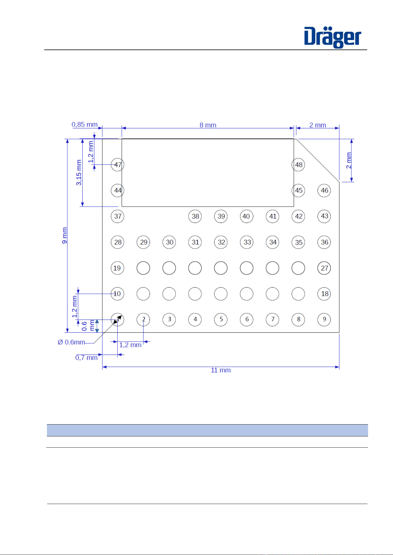
Figure 3.1-1: BT03 Module Pinout (Top View) is showing the BT03 module pinout including the required
footprint, copper and copper cut-out requirements. The copper cut-out must be maintained on all layers
underneath the antenna.
Figure 3.1-1: BT03 Module Pinout (Top View)
3.2 Library Part and Footprint
A symbol and footprint can be found in Dräger global Mentor Library:
BT-Modul
Part Number
Dataset
BT03 (9 x 11mm)
3736639
10006810
Table 1: Footprint Part-Numbers
3.3 Port Functions and Pin Assignment List
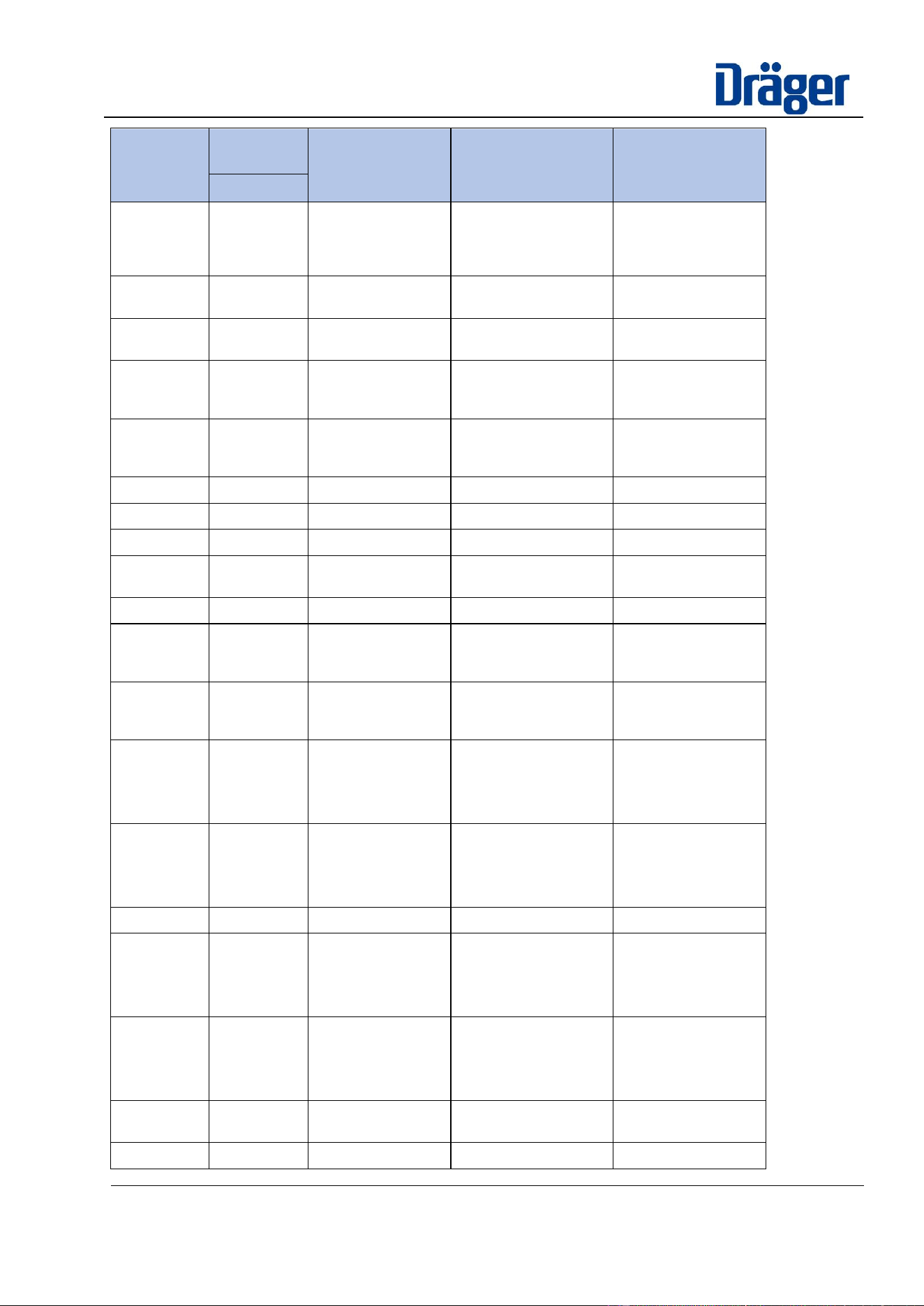
Table 2 – shows the available port pins on the Dräger BLE module BT03. And provides information regarding
the pin assignments to above shown packages. All port pins, that are shown, but not assigned to a Dräger
Module pin are physically available in the BT controller, but not accessible on the module footprint.
Datasheet
Dräger BT-modules – 11384050
Confidential Information. Property of Dräger Safety AG & Co. KGaA. All
rights reserved.
To be passed on only after written consent by Dräger Safety AG & Co.
KGaA.
Printed versions are uncontrolled
12 / 31
nRF Pin
Name
Dräger
Module pin
Function 1
Function 2
Function 3
BT03
GND
1, 3, 6, 8, 9,
12, 19 - 24,
28 - 30, 37 -
48
Ground
-
-
NFC1 /
P0.09
10
NFC antenna
connection
Digital I/O
(Standard drive only)
NFC2 /
P0.10
11
NFC antenna
connection
Digital I/O
(Standard drive only)
P0.02 / AIN0
32
Digital I/O
(Standard drive
only)
Analog Input
P0.03 / AIN1
31
Digital I/O
(Standard drive
only)
Analog Input
P0.04 / AIN2
36
Digital I/O
Analog Input
P0.05 / AIN3
35
Digital I/O
Analog Input
P0.06 / IO
-
Digital I/O
-
P0.07 /
TRACECLK
25
Digital I/O
DEBUG
Trace buffer clock
P0.08 / IO
-
Digital I/O
-
P0.11 /
TRACE2
18
Digital I/O
DEBUG
Trace buffer
TRACEDATA [2]
P0.12 /
TRACE1
27
Digital I/O
DEBUG
Trace buffer
TRACEDATA [1]
P0.13 / IO
17
Digital I/O
[in standard
configuration:
UART_TxD]
-
P0.14 / IO
16
Digital I/O
[in standard
configuration:
UART_RxD]
-
P0.15 / IO
-
Digital I/O
-
P0.16 / IO
15
Digital I/O
[in standard
configuration:
UART_RTS]
-
P0.17 / IO
14
Digital I/O
[in standard
configuration:
UART_CTS]
-
P0.18 /
nRESET
7
Digital I/O
External device reset
pin
P0.20 / IO
-
Digital I/O
-
Datasheet
Dräger BT-modules – 11384050
Confidential Information. Property of Dräger Safety AG & Co. KGaA. All
rights reserved.
To be passed on only after written consent by Dräger Safety AG & Co.
KGaA.
Printed versions are uncontrolled
13 / 31
nRF Pin
Name
Dräger
Module pin
Function 1
Function 2
Function 3
BT03
P0.21 / IO
-
Digital I/O
-
P0.22 / IO
-
Digital I/O
-
P0.25 / IO
-
Digital I/O
-
P0.26 / IO
-
Digital I/O
-
P0.27 / IO
-
Digital I/O
-
P0.28 / AIN4
33
Digital I/O
(Standard drive
only)
Analog Input
P0.30 / AIN6
34
Digital I/O
(Standard drive
only)
Analog Input
P0.31 / AIN7
-
Digital I/O
(Standard drive
only)
Analog Input
P1.00
/TRACE0
13
Digital I/O
DEBUG
Trace buffer
TRACEDATA [0]
Serial Wire Output
(SWO)
P1.09 /
TRACE3
26
Digital I/O
DEBUG
Trace buffer
TRACEDATA [3]
SWDCLK
4
Serial Wire Debug
Clock input
SWDIO
5
Serial Wire Debug
I/O
Vcc
2
Supply Voltage
N.C.
-
Not connected
Table 2 – Pin Assignment List
Note: Standard drive only I/O Pins are low frequency I/O pins with a signal frequency up to 10 kHz.
Datasheet
Dräger BT-modules – 11384050
Confidential Information. Property of Dräger Safety AG & Co. KGaA. All
rights reserved.
To be passed on only after written consent by Dräger Safety AG & Co.
KGaA.
Printed versions are uncontrolled
14 / 31
4 Electrical specifications
4.1 Absolute maximum ratings
The following specified absolute maximum ratings shall not be exceeded under all circumstances otherwise the
module might be destroyed.
Symbol
Description
min
max
Unit
V
cc
Supply voltage
-0,3
3,9
V
t
rise_Vcc
Maximum rise time of Supply Voltage (0 V to 1,7 V)
60
ms
V
IN_IO
Digital interfaces input voltage
(V
cc
<= 3.6V)
-0,3
V
cc
+ 0,3
V
V
IN_IO
Digital interfaces input voltage
(V
cc
> 3.6V)
-0,3
3,9
V
V
GND
System Ground
0
V
I
S
Operating current
0
35
mA
I
NFC
Max. NFC input current
80
mA
RF
IN
RF input level
10
dBm
T
Storage
Storage Temperature Range
-40
85
°C
n
Flash
Flash Write and Erase cycles
10.000
Cycles
t
ret
Data Retention Time (at 85°C)
10
years
Table 3: Absolut maximum operating condition
4.2 Maximum ESD ratings
Parameter
Min
typ.
Max
Unit
remarks
ESD sensitivity on all pins
1
kV
human body model class 1C
according to JEDEC JS001
500
V
charged device model according to
JESD22- C101
ESD indirect contact discharge
4
kV
According to EN 61000-4-2
Table 4: maximum ESD ratings
4.3 Recommended operating conditions
Unless otherwise specified, all given parameters are specified for an ambient temperature of 25°C with a supply
voltage of 3.3V.
Symbol
Description
min
typ.
max
Unit
V
cc
Supply voltage
2,5
3,6
V
V
POR
Vcc Supply voltage threshold for power-on reset
1,75
V
T
amb
Operating temperature range
-40
25
85
°C
T
junction
Junction temperature
90
°C
Table 5 : Recommended operating conditions
Datasheet
Dräger BT-modules – 11384050
Confidential Information. Property of Dräger Safety AG & Co. KGaA. All
rights reserved.
To be passed on only after written consent by Dräger Safety AG & Co.
KGaA.
Printed versions are uncontrolled
15 / 31
4.3.1 Current consumption
The following consumption values have been taken with the Power Profiler tool from Nordic and a
communication test-setup of two nRF52840 DK-Boards operating the Dräger BLE platform firmware. The power
consumption depends on the individual settings of intervals and payload size of transferred data, therefore the
summarized values provide an overview about typical ranges in dependency to a set of chosen settings but
must not be considered as fixed reference for any product.
Settings: max. output power = 0 dBm
Mode
Description
accumulated
Charge
typical max
Current
Idle
no BLE communication
Duration: 120 sec.
3,71 ... 3,99 mC
16,47 mA
Advertising
Adv. Interval: 1 sec,
Duration: 120 sec,
Frame size: 14 bytes “name”
12 bytes MSD
4,33 ... 5,41 mC
16,07 mA
Scanning
Scan. Interval: 900 ms,
Window: 150 ms
Duration: 120 sec,
215,03 ... 215,93
mC
18,3 mA
Passthrough
Payload: 100 x 1kByte
Connection interval: 100ms
Connection interval: 200ms
22,87 ... 24,72 mC
23,20 mA
Payload: 200 x 0,5kByte
Connection interval: 100ms
Connection interval: 200 ms
23,25 ... 25,26 mC
23,9 mA
Payload: 400 x 0,25kByte
Connection interval: 100ms
Connection interval: 200 ms
29,70 ... 33,79 mC
23,8 mA
Table 6 : Current consumption
Datasheet
Dräger BT-modules – 11384050
Confidential Information. Property of Dräger Safety AG & Co. KGaA. All
rights reserved.
To be passed on only after written consent by Dräger Safety AG & Co.
KGaA.
Printed versions are uncontrolled
16 / 31
4.3.2 RF-Performance
4.3.2.1 Receiver Sensitivity
V
cc
= 2,5 V to 3,6 V, T
ambient
= +20°C
Measured conducted according to “Bluetooth Core Specification v5.4 – RFPHY TS.p23”
Symbol
Description
min
typ.
max
Unit
P
sense_IT_SP_1M_BLE
Sensitivity, 1 Mbps BLE ideal
transmitter, packet length
<=37 bytes, BER=1E-3
-92
dBm
P
sense_IT_LP_1M_BLE
Sensitivity, 1 Mbps BLE ideal
transmitter, packet length
>=128bytes, BER=1E-4
-91
dBm
P
sense_IT_SP_2M_BLE
Sensitivity, 1 Mbps BLE ideal
transmitter, packet length
<=37 bytes
-89
dBm
P
sense_IT_BLE_LE125k
Sensitivity, 125 kbps BLE
mode
-100
dBm
P
sense_IT_BLE_LE500k
Sensitivity, 500 kbps BLE
mode
-96
dBm
Table 7: Receiver Sensitivity
4.3.2.2 Transmit Power
V
cc
= 2,5 V to 3,6 V, T
ambient
= +20°C
Measured conducted according to “Bluetooth Core Specification v5.4 – RFPHY TS.p23”
Symbol
Description
min
typ.
max
Unit
LP_RF
max. output power over Antenna with
8 dBm Power Level
4
6
8
dBm
Table 8: Transmit Power
IMPORTANT HINT: Please refer to chapter 8.2 for further information about limitations of the transmit power
setting.
4.3.3 Startup times
The typical start-up times after Power-On Reset (POR), Hardware reset via nRESET or Software reset are:
Symbol
Description
min
typ.
max
Unit
t
total_start-up
Total start-up time
1518
ms
t
Bootloader_start-up
Start-up time of the
bootloader
460
ms
t
bl_loading_fw
Firmware loading time of the
bootloader
620
ms
t
fw_start-up
Start-up time of the firmware
430
ms
t
init_communication
Time until communication is
available after firmware start-
up
8
ms
Table 9 - Start-up times
Datasheet
Dräger BT-modules – 11384050
Confidential Information. Property of Dräger Safety AG & Co. KGaA. All
rights reserved.
To be passed on only after written consent by Dräger Safety AG & Co.
KGaA.
Printed versions are uncontrolled
17 / 31
4.3.4 LFXO crystal specifications
Symbol
Parameter
typ.
Unit
F
NOM_LFXO
Nominal Low Frequency Oscillator
Frequency
32,768
kHz
F
TOL_LFXO_BLE
Low Frequency Oscillator
Tolerance
± 20
+
±3 / year
ppm
Table 10: LFXO crystal specification
4.3.5 nRESET pin
Parameter
Min
typ.
Max
Unit
remarks
Internal Pull Up resistance
13
kOhm
RESET duration
55
ms
Table 11: nRESET pin parameters
4.3.6 Digital pins
Symbol
Parameter
Min
typ.
Max
Unit
V
IN_Low
Low Level Input Area
0
0,3 x V
cc
V
V
IN_High
High Level Input Area
0
0,7 x V
cc
V
Table 12: digital pins parameter
4.3.7 BT03 Radiation patterns
The radiation patterns of the BT03 module are available for internal use only. Please refer to ARAS document
12235506.
Datasheet
Dräger BT-modules – 11384050
Confidential Information. Property of Dräger Safety AG & Co. KGaA. All
rights reserved.
To be passed on only after written consent by Dräger Safety AG & Co.
KGaA.
Printed versions are uncontrolled
18 / 31
5 Exploration Tests
5.1 Data Throughput
Since Bluetooth Low Energy (BLE) is designed for constraint components with limited energy, a set of
parameters comes along to configure the communication as an optimized tradeoff between communication use
cases and the corresponding energy consumption. The set of parameters includes configurable options like
connection interval, peripheral-latency and max. payload packet size and many other details, which affect the
overall possible throughput. The following section summarizes the most important parameters and provides an
overview of their impact on throughput in conjunction with some typical settings and gives examples of payload
sizes.
Anyway, the BT-module operates as gateway, therefore the weakest chain link limits the maximum throughput
capability of the gateway– this includes also the UART-communication to the product controller.
In case the UART supports bi-directional communication with reactive hardware-handshake RTS/CTS lines and
a high baud rate setting > 500 kbps, the UART is typically not the limiting instance.
If not specified otherwise, the following settings were used.
Parameter
Setting value
Unit
Connection Interval (BLE)
100
ms
Peripheral Latency (BLE)
0
-
LL MTU (BLE)
251
bytes
L2CAP / ATT MTU (BLE)
498
bytes
Payload Size (Application)
1024
bytes
Table 5.1-1: default settings & pre-conditions of data throughput explorations
5.1.1 Buffer configuration
The gateway functionality requires buffer capabilities to assure intermediate storage of RX/TX communication
frames. This is necessary to avoid data loss of incoming receive events on both physical interfaces, while the
COM-dispatcher performs its task to route the frames to corresponding handlers.
Based on optimization analysis to achieve the maximum throughput, following buffer configurations for BLE
RX/TX frames have been derived and established:
• CONFIG_BT_BUF_ACL_TX_COUNT ≥ 25
• CONFIG_BT_BUF_ACL_RX_COUNT ≥ 25
5.1.2 Peripheral Latency
The Peripheral Latency is a BLE parameter that defines the acceptable tolerance of unused connection intervals
by the peripheral before the connection loss detection is triggered. This feature is intended to reduce energy
consumption on a BLE peripheral if no data content update is present.
The value of the parameter is given as a factor of connection intervals within the range [0…499] and could be
modified dynamically by the product application during runtime via the service interface.
The default setting of the BLE-platform architecture is 7 but could be adjusted to product demands for each
product firmware individually.
Datasheet
Dräger BT-modules – 11384050
Confidential Information. Property of Dräger Safety AG & Co. KGaA. All
rights reserved.
To be passed on only after written consent by Dräger Safety AG & Co.
KGaA.
Printed versions are uncontrolled
19 / 31
5.1.3 Payload size of packages to transmit via BLE
The size of the packages to transmit via the passthrough services has the highest impact on the data-rate.
Larger packets have an advantage of less overhead on packet-header and arbitration but at a specific point
larger packets have diminishing returns.
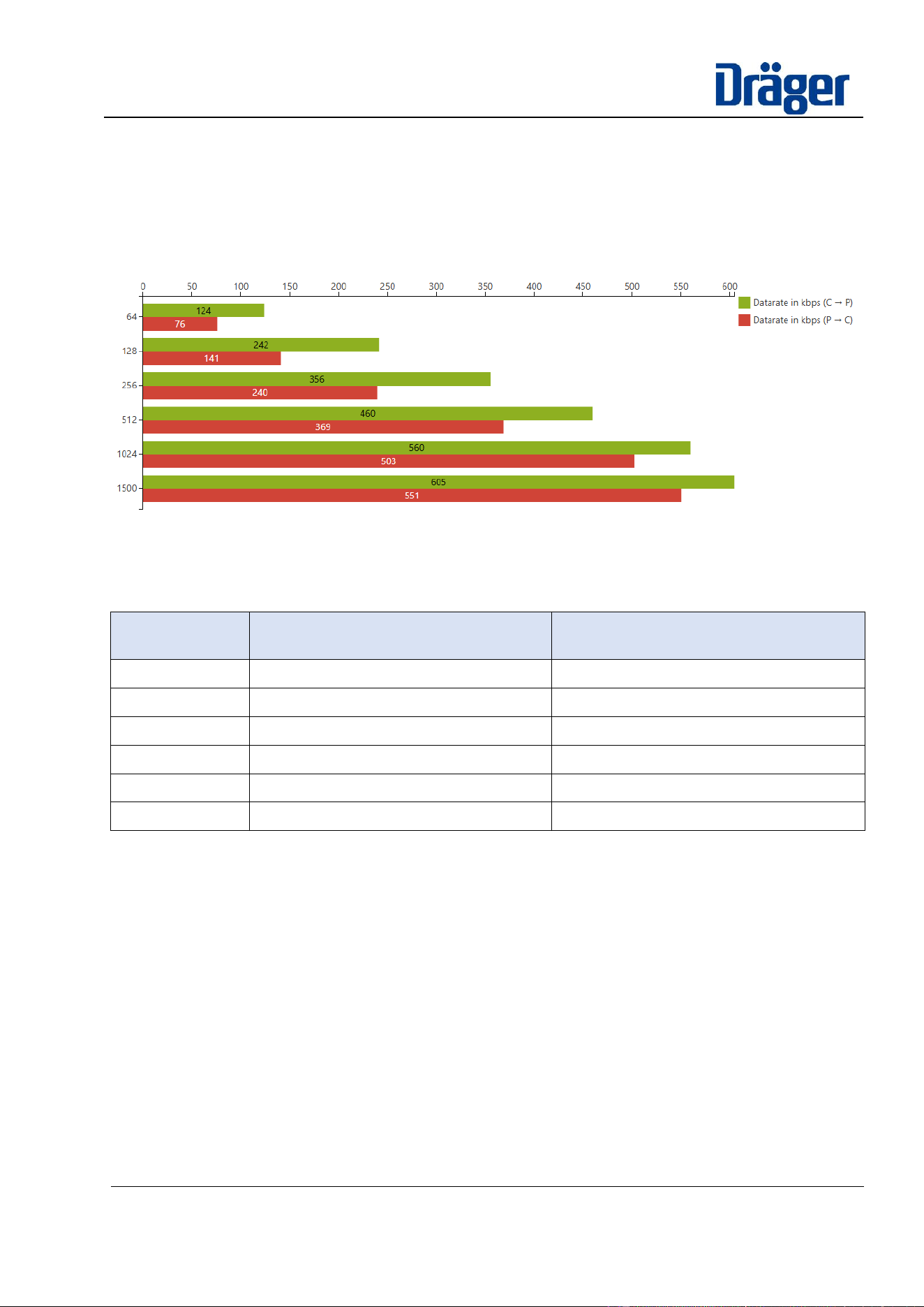
Below is a chart, which shows the effect of the package size on BLE throughput. The measurements were
taken when sending from a BLE device to the product firmware. A connection interval of 100ms was used.
Figure 5.1-1: data-rate in dependency to payload sizes.
Observed deviations of data-rates are not caused by the BLE roles only (C=Central; P=Peripheral), but in
conjunction with associated BLE GATT Client and BLE GATT Server instances associated to a role.
payload size
[bytes]
data-rate as Central
with a GATT-Client [kbps]
data-rate as Peripheral
with a GATT-Server [kbps]
64
124
76
128
242
141
256
356
240
512
460
369
1024
560
503
1500
605
551
Table 13: data-rate in dependency of payload packet size
5.1.4 Connection Interval
The connection interval is a BLE parameter that defines the periodic time interval, when connected peers are
scheduled to perform communication. The parameter is negotiated during connection establishing scenarios,
between BLE Peripheral and BLE-Central devices. The BLE peripheral could suggest a preferred setting – the
BLE central will admit the concluded setting.
Datasheet
Dräger BT-modules – 11384050
Confidential Information. Property of Dräger Safety AG & Co. KGaA. All
rights reserved.
To be passed on only after written consent by Dräger Safety AG & Co.
KGaA.
Printed versions are uncontrolled
20 / 31
5.1.4.1 Throughput with payload chunks of 1024 bytes
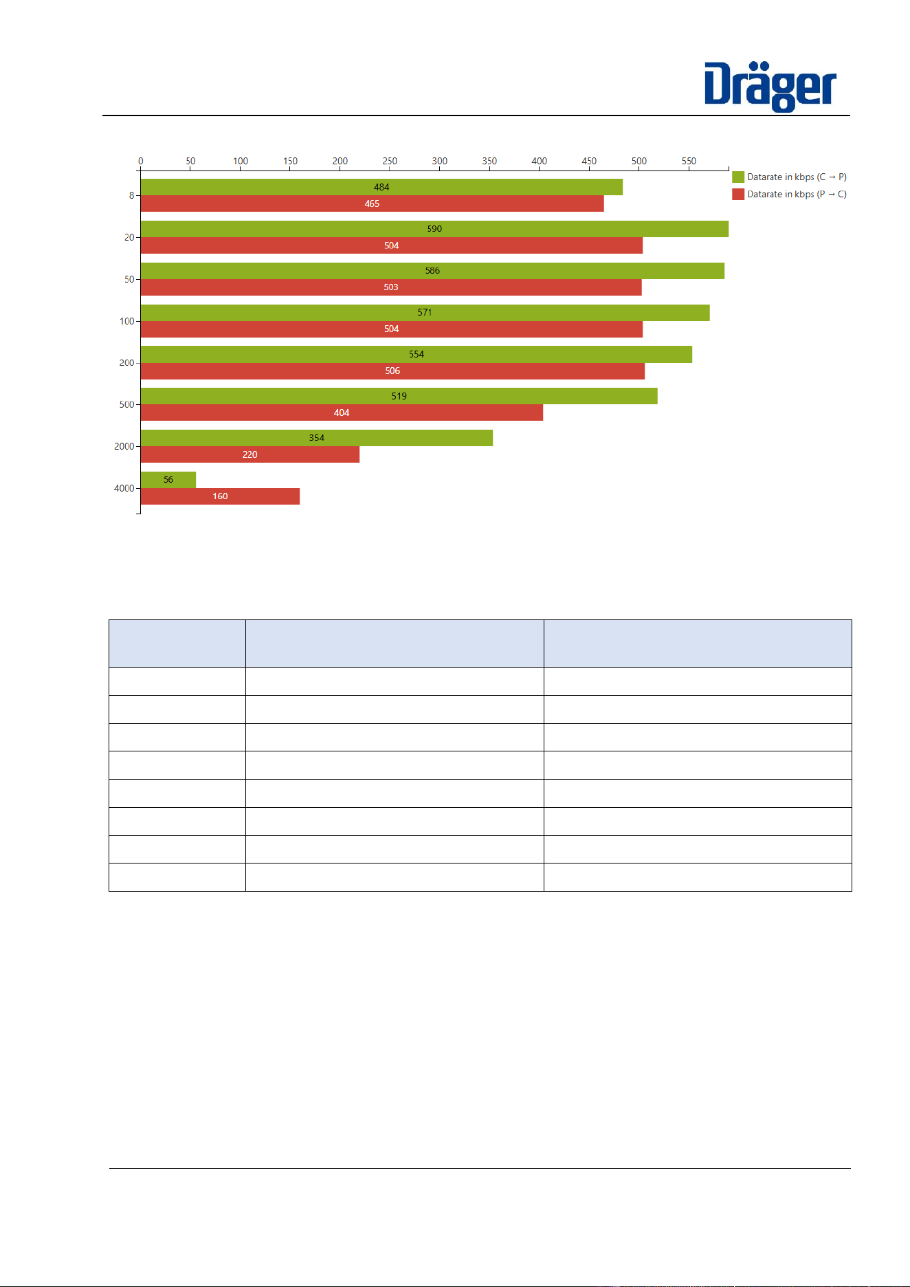
Figure 5.1-2: data-rates in dependency of connection interval with payload-chunks of 1024 bytes
Observed deviations of data-rates are not caused by the BLE roles only (C=Central; P=Peripheral), but in
conjunction with associated BLE GATT Client and BLE GATT Server instances associated to a role.
connection
interval [ms]
data-rate as Central
with a GATT-Client [kbps]
data-rate as Peripheral
with a GATT-Server [kbps]
8
484
465
20
590
504
50
586
503
100
571
504
200
554
506
500
519
404
2000
354
220
4000
56
160
Table 14: data-rates in dependency of connection interval with payload-chunks of 1024 bytes
Datasheet
Dräger BT-modules – 11384050
Confidential Information. Property of Dräger Safety AG & Co. KGaA. All
rights reserved.
To be passed on only after written consent by Dräger Safety AG & Co.
KGaA.
Printed versions are uncontrolled
21 / 31
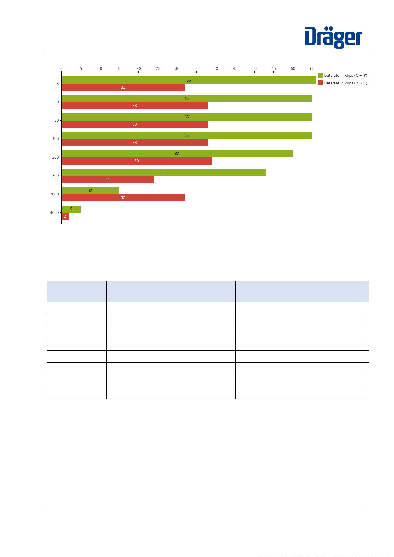
5.1.4.2 Throughput with payload chunks of 32 bytes
Figure 5.1-3: data-rates in dependency of connection interval with payload-chunks of 32 bytes
Observed deviations of data-rates are not caused by the BLE roles only (C=Central; P=Peripheral), but in
conjunction with associated BLE GATT Client and BLE GATT Server instances associated to a role.
connection
interval [ms]
data-rate as Central
with a GATT-Client [kbps]
data-rate as Peripheral
with a GATT-Server [kbps]
8
66
32
20
65
38
50
65
38
100
65
38
200
60
39
500
53
24
2000
15
32
4000
5
2
Table 15: data-rates in dependency of connection interval with payload-chunks of 32 bytes

Datasheet
Dräger BT-modules – 11384050
Confidential Information. Property of Dräger Safety AG & Co. KGaA. All
rights reserved.
To be passed on only after written consent by Dräger Safety AG & Co.
KGaA.
Printed versions are uncontrolled
22 / 31
6 Mechanical specifications
6.1 Maximum height BT03
The maximum height of BT03 module is 3.16mm. During integration into the final product also consider, that
solder paste adds additional height.
For portable host devices take care about the minimum distance mentioned in FCC approval and ISED approval
between antenna and contactable surface of the device. (see chapters 10.2 & 10.3)

Datasheet
Dräger BT-modules – 11384050
Confidential Information. Property of Dräger Safety AG & Co. KGaA. All
rights reserved.
To be passed on only after written consent by Dräger Safety AG & Co.
KGaA.
Printed versions are uncontrolled
23 / 31
7 Design Checklist
7.1 UART Interface
The port pins of the Bluetooth controller are highly configurable, which means the UART pins used for controlling
the BT03 module are not fixed by hardware. By default, our Bluetooth platform assigns P0.13, P0.14, P0.16,
and P0.17 for UART communication, as detailed in section 3.3 Port Functions and Pin Assignment List. If you
modify these assignments in the software, ensure that the corresponding pins are correctly configured to
maintain proper communication with the BT03 module.
For enhanced electromagnetic immunity and reduced emissions, it is also advisable to add a low-pass filter to
the communication lines. The filter’s cutoff frequency should be set well above the maximum UART
communication frequency to prevent interference with data transmission.
7.2 External capacitors
The BT03 module is engineered to operate reliably without the need for external capacitors. However, for
enhanced stability, it is recommended to add an external buffer capacitor (10 nF to 100 nF) to Vcc (Pin 2).
7.3 RESET circuit
By default, P0.18 serves as the external reset pin for the BT03 module. If external reset functionality is used,
an external reset circuit must be implemented with at least a high-value pull-up resistor (e.g., 100 kΩ to 220 kΩ)
connected to Vcc. To improve immunity to transients and electromagnetic interference, it is also recommended
to add a decoupling capacitor. Although this is not strictly required—since the module successfully passes
immunity testing up to 10 V/m without an external decoupling capacitor—adding one provides an extra margin
of robustness.

Datasheet
Dräger BT-modules – 11384050
Confidential Information. Property of Dräger Safety AG & Co. KGaA. All
rights reserved.
To be passed on only after written consent by Dräger Safety AG & Co.
KGaA.
Printed versions are uncontrolled
24 / 31
8 Limitations
This section summarizes known limitations associated with the Dräger BT-module BT03.
8.1 No compliance for Safety Integrity Level (SiL) applications
The BT-Modules and the Dräger BLE-Software are not engineered in consideration of any SiL-requirements or
associated engineering process qualities of IEC61508 or IEC61511.
Given by impact of physical environmental conditions, any established Bluetooth connection by Dräger
Bluetooth modules is appropriate to guarantee reliability of the data communication within a defined time-
tolerance. Therefore, the Bluetooth communication must not be used for any SIL-relevant real-time system
communication.
Anyhow the technology could be used to transfer safety-critical content in context of maintenance or service
use cases. The protection of completeness, consistency and authentication of content could be achieved by
usage of proper transport- and application layer protocol as well as signature-checkup on transferred content.
(i.e.: Firmware-Updates, download of logger or upload of configuration data)
8.2 Setting of maximal transmitting radio output power
The setting of the maximal transmitting radio output power for the nRF52840 SoC is configurable by a static
parameter given within the nRF Connect SDK software at compile-time.
The setting impacts the possible radio range, human body exposure considering equal environmental conditions
and of course the energy consumption of the module at comparable communication use cases.
IMPORTANT: The radio approval and validated human exposure conformity for the pre-certified BT-modules
will become not applicable, if the maximum radio power output setting is increased above the configured value
used and validated by the performed confirmation tests for the BT-modules.
To achieve a radio approval and human exposure conformity with increased settings, extra effort in time and
costs must be considered by the products. Even the risk rises, that conformity for human exposure might not
be achievable at all.
It is not admitted to BLE-platform developers to change the setting of this parameter for a specific product BLE-
firmware without a confirmed change request, signed by responsible product stakeholders. The confirmation
document shall include an unambiguous statement about the mentioned consequences and risk.
Datasheet
Dräger BT-modules – 11384050
Confidential Information. Property of Dräger Safety AG & Co. KGaA. All
rights reserved.
To be passed on only after written consent by Dräger Safety AG & Co.
KGaA.
Printed versions are uncontrolled
25 / 31
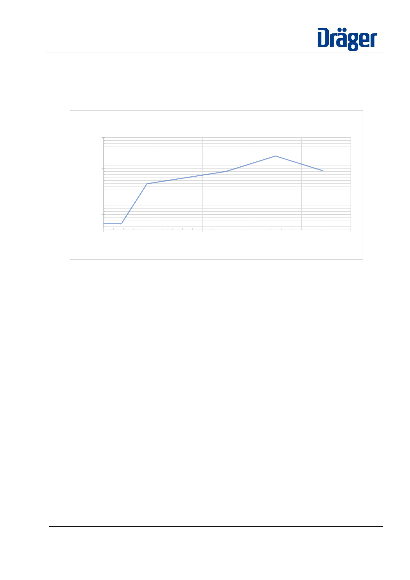
9 Soldering profile
The recommended soldering profile can be found in the following graph. While modifying the given soldering
profile to meet other component requirements ensure that the maximum temperature does not exceed 250°C
and that the temperature above 220°C is present for at least 20 seconds, but not longer than 50 seconds.
Table 16: Solder profile
Note: Nordic Semiconductor recommends a maximum of three soldering steps for the nrF52840 chip.
Since the chip has already been soldered once during module production, a maximum of two soldering
steps may be performed during production of the final product.
0
50
100
150
200
250
300
0 50 100 150 200 250
Temperature
°C
Time sek.
Solderprofile
Datasheet
Dräger BT-modules – 11384050
Confidential Information. Property of Dräger Safety AG & Co. KGaA. All
rights reserved.
To be passed on only after written consent by Dräger Safety AG & Co.
KGaA.
Printed versions are uncontrolled
26 / 31
10 Approvals
10.1 Approval information in production
10.1.1 Due to small size of the modules, it is not possible to laser all approval information for all countries
on the shield can for BT03. Therefore, an external shield can label was created and an approval
label for the package was created.
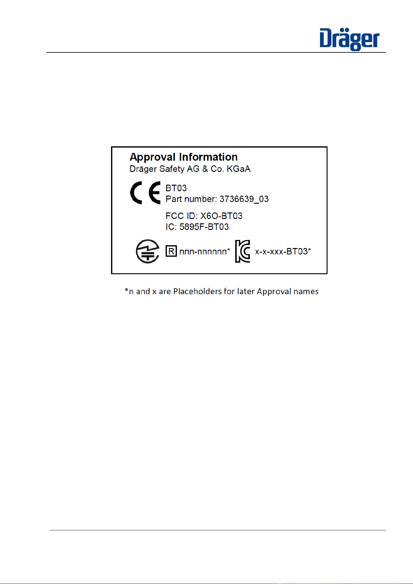
10.1.2 Package approval label BT03
Figure 10.1-1 - Approval label for packaging BT03
Placeholders and the corresponding logos are not printed during production until they contain a valid
approval.
The approval label can be found under the ARAS document number 11382802.
10.2 Federal Communicators Commissions for US (FCC)
The BT-module (BT03) with the equipped antenna comply to the requirements of Class 2 digital devices of part
15 of the FCC rules.
The Transmitter is subjected to the following conditions:
1. This device may not cause harmful interference, and
2. This device must accept any interference received, including interference that may
cause undesired operation.
The module is not for sale and the user manual integration instructions are internal confidential manufacturing
documents.
Datasheet
Dräger BT-modules – 11384050
Confidential Information. Property of Dräger Safety AG & Co. KGaA. All
rights reserved.
To be passed on only after written consent by Dräger Safety AG & Co.
KGaA.
Printed versions are uncontrolled
27 / 31
10.2.1 List of approved Antennas for BT03
Manufacturer
Part-Number
Type
Frequency
Band
max. Gain (dBi)
Johanson
Dielectrics Inc
2450AT18D0100
Chip Antenna
2,4 GHz
0.93 @ 2403MHz
2.01 @ 2443MHz
0.60 @ 2483MHz
Table 17: List of approved Antennas
10.2.2 FCC ID BT03
The BT03 module has been tested to fulfill the FCC requirements.
Product Name: BT03
FCC ID: X6O-BT03
Due to the Module size, the FCC identifier is displayed in the specification and must also be displayed in the
instruction manual of the device. It cannot be displayed readable on the module’s label due to the limited size.
Please see Reasoning document in ARAS (Doc 12243124).
• The following information must be indicated on the host device of this module.
When installing it in a mobile equipment.
When installing it in a portable equipment.
It is necessary to take a SAR test with your set mounting this module.
Class II permissive change application is necessary using the SAR report.
To comply with RF exposure conditions the host device incorporating the BT03 must ensure a separation
distance with at least of N.NNN mm measured between the Antenna and outside of the housing.
10.3 Innovation, Science, and Economic Development (ISED) for Canada
The Module (BT03) are licensed to meet the regulatory requirements of ISED.
Due to the Module size, the IC identifier is displayed in the specification and must also be displayed in the
instruction manual of the device. It cannot be displayed readable on the module’s label due to the limited size.
Please see Reasoning document in ARAS (Doc 12243126).
This device contains license-exempt transmitter(s)/receiver(s) that comply with Innovation, Science and
Economic Development Canada’s license-exempt RSS(s). Operation is subject to the following two conditions:
1. This device may not cause interference.
Contains Transmitter Module FCC ID: X6O-BT03
Contains FCC ID: X6O-BT03
or
This device complies with part 15 of the FCC Rules. Operation is subject to the following two
conditions: (1) This device may not cause harmful interference, and (2) this device must accept any
interference received, including interference that may cause undesired operation.
This equipment complies with FCC radiation exposure limits set forth for an uncontrolled environment
and meets the FCC radio frequency (RF) Exposure Guidelines. This equipment should be installed
and operated keeping the radiator at least 20cm or more away from person’s body.
Datasheet
Dräger BT-modules – 11384050
Confidential Information. Property of Dräger Safety AG & Co. KGaA. All
rights reserved.
To be passed on only after written consent by Dräger Safety AG & Co.
KGaA.
Printed versions are uncontrolled
28 / 31
2. This device must accept any interference, including interference that may cause undesired operation
of the device.
L’émetteur/récepteur exempt de licence contenu dans le présent appareil est conforme aux CNR d’Innovation,
Sciences et Développement économique Canada applicables aux appareils radio exempts de licence.
L’exploitation est autorisée aux deux conditions suivantes:
1. L’appareil ne doit pas produire de brouillage.
2. L’appareil doit accepter tout brouillage radioélectrique subi, même si le brouillage est susceptible d’en
compromettre le fonctionnement.
10.3.1 List of approved Antennas
Manufacturer
Part-Number
Type
Frequency
Band
max. Gain (dBi)
Johanson
Dielectrics Inc
2450AT18D0100
Chip Antenna
2,4 GHz
0.93 @ 2403MHz
2.01 @ 2443MHz
0.60 @ 2483MHz
Table 18: List of approved Antennas
10.3.2 License ID BT03
Product Name (HVIN): BT03
License ID - IC: 5895F-BT03
To comply with RF exposure conditions the host device incorporating the BT03 must ensure a separation
distance with at least of N.NNNN mm measured between the Antenna and outside of the housing.
10.4 KC Certification for BT03
Approval pending
10.4.1 KC Certification BT03
Approval pending
10.4.2 KC Mark BT03
Approval pending
10.5 JP Certification for BT03
Approval pending
10.5.1 JP Certification BT03
Approval pending
10.5.2 JP Mark BT03
Approval pending

Datasheet
Dräger BT-modules – 11384050
Confidential Information. Property of Dräger Safety AG & Co. KGaA. All
rights reserved.
To be passed on only after written consent by Dräger Safety AG & Co.
KGaA.
Printed versions are uncontrolled
29 / 31
10.6 European Conformity According to RED (2014/53/EU)
The Dräger modules described in this Product Specification comply with the standards according to the RED
(2014/53/EU) articles:
The maximum output power is +10 dBm within a frequency range of 2.402 MHz to 2.480MHz.
<<EU Conformity pending>>
Figure 10.6-1 : Eu-DoC for Dräger Bluetooth Module BT03
10.7 Bluetooth SIG
The Dräger Bluetooth Platform is listed in the Bluetooth SIG Listing. See the following link:
Launch Studio - Listing Details (bluetooth.com)
The SIG Registration is not fixed to the HW. Dräger listed Controller and Host Subsystems, which can be easily
transferred to new products and HW.
Datasheet
Dräger BT-modules – 11384050
Confidential Information. Property of Dräger Safety AG & Co. KGaA. All
rights reserved.
To be passed on only after written consent by Dräger Safety AG & Co.
KGaA.
Printed versions are uncontrolled
30 / 31
11 Glossary
11.1 Abbreviation & Acronyms
Abbreviation
Explanation / Description
BLE
Bluetooth Low Energy
BT
Bluetooth
COM
Communication
CTS
Clear To Send (control line to synchronize communication peers, indicates a COM-request on a
handshake line and expects confirmed readiness from the connected peer on RTS)
DFU
Device Firmware Update
DTM
Direct Test Mode
EDR/BR
Endpoint Detection and Response / Broadcast Receiver
ESD
Electrostatic Discharge
FCC
Federal Communications Commission
GATT
Generic Attribute Profile
GDC
Gas Detection Connect (Dräger Cloud Application)
GPIO
General Purpose Input Output (typical digital interface of microcontroller, configurable in direction
and kind of its usage as input or output signal)
HW
Hardware
ID
Identifier
IO
Input/Output (digital interface of microcontrollers)
MCU
Microcontroller Unit
MTU
Maximum Transfer Unit
NFC
Near Field Communication (specific radio communication technology for very short ranges)
OS
Operating System (Software)
OTA
Over the Air
PCB
Printed Circuit Board
RF
Radio Frequency
RTS
= RFR = Ready for Receive (acknowledge line to synchronize communication peers, indicates
readiness to receive as reaction on an indicated COM-request by CTS)
RX/TX
Direction of Communication: RX = Receive, TX = Transmit
SDK
Software Development Kit
SIG
Special Interest Group
SiL
Safety Integrity Level
SMP
Simple Management Protocol
SOC
System on Chip
UART
Universal Asynchronous Receiver-Transmitter
Table 19: Abbreviations& Acronyms

Datasheet
Dräger BT-modules – 11384050
Confidential Information. Property of Dräger Safety AG & Co. KGaA. All
rights reserved.
To be passed on only after written consent by Dräger Safety AG & Co.
KGaA.
Printed versions are uncontrolled
31 / 31
11.2 References
[1] Nordic: nRF52840_ProductSpecification_v1.10.pdf
[2] Part F Direct Test Mode
[3] sdk-nrf/samples/bluetooth/direct_test_mode/README.rst at v2.5.1 · nrfconnect/sdk-nrf · GitHub