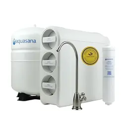
AQ-SFRO2
Under Sink Water Filter
SmartFlow
®
Reverse Osmosis
Owner’s Manual

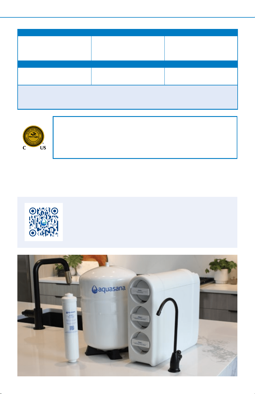
Meet clean, healthy water. Your new SmartFlow
®
Reverse Osmosis uses
both Claryum
®
and reverse osmosis ltration to reduce up to 99.99% of 90
contaminants
*
. The system’s patented SmartFlow
®
technology is engineered to
provide you with more pure water, less water waste, and longer lter life than
the average RO system.
Enjoy the peace of mind that comes from knowing our award-winning lter
technology is working for you.
AQ-SFRO2
Under Sink Water Filter
SmartFlow
®
Reverse Osmosis
TABLE OF CONTENTS
Box Contents ................................................................................................................ 1
Installation Steps .................................................................................................... 2-11
Care & Safeguards ................................................................................................12-14
Filter Replacements ................................................................................................... 15
Performance & Certications ................................................................................... 16
Troubleshooting Guide ....................................................................................... 17-19
Warranty .................................................................................................................... 20
Water for Life
®
........................................................................................................... 21
*See Performance & Certications (page 16) for specics about contaminants reduced.
Scan to view the
SmartFlow
®
Reverse
Osmosis installation video.
STAGE 1 STAGE 2 STAGE 3
STAGE 4
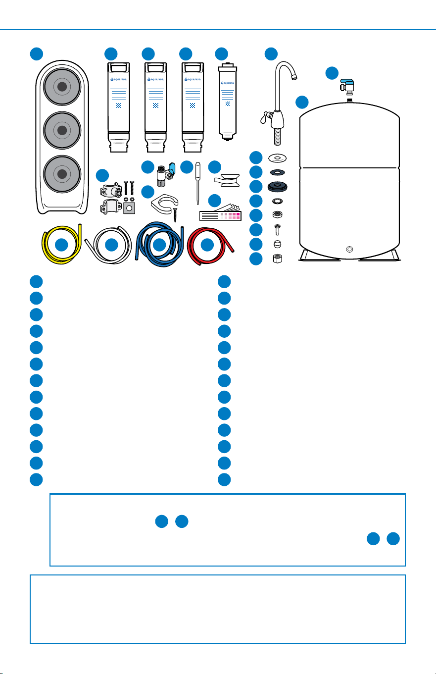
BOX CONTENTS 1
System Manifold
Stage 1: Carbon Block
Stage 2: SmartFlow
®
Membrane
Stage 3: Advanced Carbon Block
Stage 4: Remineralizer
Faucet
Faucet Base
Rubber Washer
Faucet Spacer
Lock Washer
Faucet Nut
Plastic Tube Insert
Plastic Collar
Chrome Nut
Water Tank Valve
Water Tank and Stand
Drain Saddle Kit
Easy-Connect Shut-O Valve
Remineralizer Bracket
Eye Dropper
Plumber's Tape
Water Test Kit
Yellow 1/4” Tubing
White 1/4” Tubing
Blue 1/4” Tubing (2)
Red 1/4” Tubing
2 3 4
24
2
1
3
4
5
10
6
7
8
9
11
12
13
14
1 5 6
14
15
16
17
18
19
23
22
15
16
Box contents will be packaged in multiple boxes.
Before beginning installation, please ensure all parts listed are present. If any part is
missing or damaged, do not attempt to install the system.
Please contact Customer Support for replacement parts at 866-662-6885.
17
2120
NOTE: If you purchased a SmartFlow
®
Reverse Osmosis without a dedicated faucet,
contents will not include
6
-
14
.
If you received a dedicated faucet with the 1/4” blue tubing attached, parts -
will not be included. This manual addresses this installation in step 2.
18
7
8
9
10
11
12
13
25
19
20
21
22
23
24
25
12 14
26
26

2
INSTALLATION STEPS2
For models that include a dedicated faucet:
NOTE: This system requires an existing faucet hole at least 1/2” in diameter in
the sink or countertop to install the supplied dedicated faucet. You may also
replace an existing kitchen sink sprayer, soap dispenser, or use pre-existing
hole on the sink or countertop.
If using a hole from a current dedicated faucet, ensure the hole is at least 1/2”
in diameter.
If drilling a new hole, ensure faucet body will mount at against surface and there is
sucient tubing between faucet body and system manifold. If drilling, we strongly
recommend using a professional. Please wear safety glasses when drilling.
For model without a dedicated faucet:
NOTE: This system requires an existing faucet hole, please refer to the
installation guide of the faucet purchased to determine hole size needed to drill.
This system requires tubing to be 1/4” outside diameter. If you have 3/8” outer
diameter tubing, you will need to purchase quick connect adapters.
1
Setup
A. Unpack and unwrap box contents.
B. Turn o COLD water supply. Turn on the cold water at the kitchen faucet
to release pressure and allow water to drain from the line.
C. Temporarily place system manifold and water tank into the under sink
cabinet or desired location to ensure adequate space and proper positioning.
D. Ensure all tubing lengths are sucient for making connections. Do not cut
tubing before following step 2.
E. Remove system manifold and water tank from under your sink to begin
installation.
• Tape measure
• Phillips head screwdriver
• Drill with 1/4" bit
Tools recommended for installation
NOTE: We recommend using a professional if pipe cutting or drilling is required.
Basic plumbing knowledge is recommended prior to installing this unit.
• Adjustable wrench
• Bleach
• Pencil
• Pan or bucket
• Utility knife
• Safety glasses
NOTE: Certain plumbing codes mandate the installation of either an air gap faucet
or a backow preventer on the drain connection when installing reverse osmosis
(RO) water ltration systems. This requirement is designed to prevent cross-
contamination of drain water with the drinking water supply, ensuring the system
complies with health and safety standards.
Before installation, consult your local plumbing codes or a licensed plumber to
determine the specic requirements in your area. Failure to comply with local codes
may result in improper operation or contamination of the water supply.
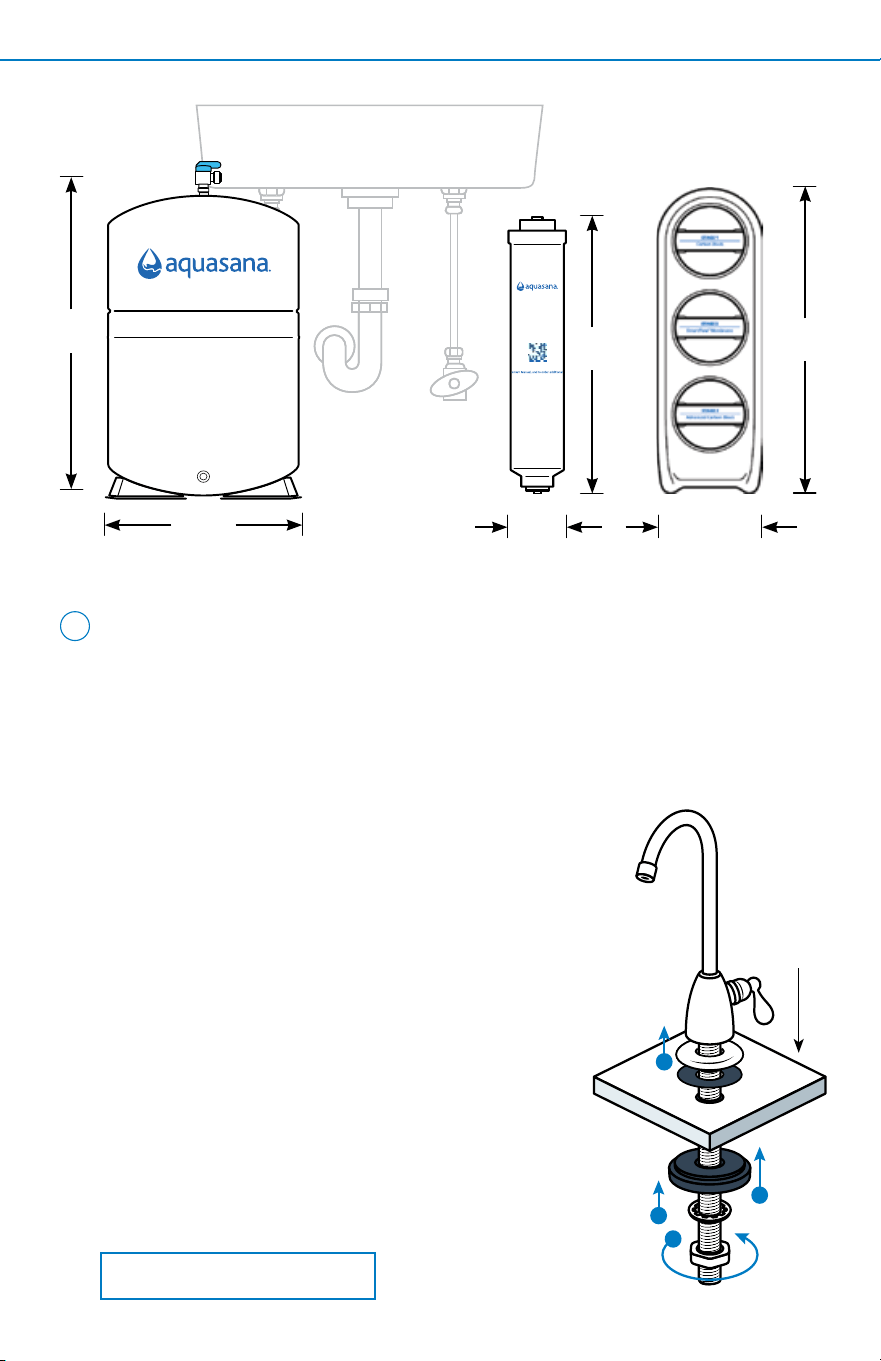
INSTALLATION STEPS 3
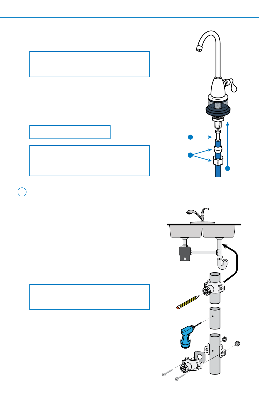
Install Dedicated Faucet
2
2.125"
(5.4 cm)
15.7"
(39.87 cm)
9.06"
(23 cm)
12.93"
(33 cm)
10.25"
(26 cm)
4.5"
(11.5 cm)
STAGE 4
__________________________________
Remineralizer
AQ-SFRO-REMIN
Adds back calcium to improve
water taste and pH balance.
Replace Remineralizer every
6 months for best use.
Scan to view Performance Data Sheet,
A. Unscrew the nut from the threaded faucet base.
Slide the metal faucet base onto dedicated
faucet, followed by the rubber washer. Insert
faucet into drilled hole.
B. From underneath the sink, slide faucet spacer
onto dedicated faucet.
C. Slide lock washer onto dedicated faucet.
D. Screw the faucet nut back on to secure faucet and
parts to countertop. Tighten with a wrench.
D
B
C
A
COUNTERTOP
DRAWING NOT TO SCALE, SYSTEM AND TANK ENLARGED.
If you purchased a separate faucet, skip step 2 (Install Dedicated Faucet)
and follow the faucet manufacturer’s installation manual. Once the faucet is
installed, proceed to step 3 on page 4.
For Separate Faucet
Follow steps 2 A-E by assembling parts over tubing.
Once complete, proceed to step 3.
For Pre-Attached Tubing to Dedicated Faucet
For Non-Pre-Attached Tubing
NOTE: Do not over tighten.
2
INSTALLATION STEPS4
A. Identify drain outlet location on drainpipe
to install drain clamp. Do not install drain
clamp on the same drainpipe as garbage
disposal. Mount drain clamp on a section of
vertical or horizontal drainpipe that is above
the drain trap and unobstructed for drilling.
B. Using the drain connector hole as a
template, drill a 1/4” hole into the drainpipe.
Only drill through one side of the drainpipe.
3
WARNING: Ensure all electrical appliances
and outlets are turned o at circuit breaker
before continuing. Please wear safety
glasses when drilling.
C. Take the connection half of the drain clamp
and attach the foam gasket. Do so by
removing the center hole and protective cover
from the back of the foam gasket. Align the
foam gasket hole with the hole on the inside
of the drain clamp. The adhesive side of the
foam gasket should be facing the inside of the
drain clamp. Press rmly to attach.
Install Drain Saddle
E. Slide the chrome nut onto the 1/4” blue tubing, followed
by the white plastic collar.
NOTE: Do not over tighten.
G
E
F
NOTE: If your faucet includes pre-attached
tubing, use wrench to tighten the chrome
nut and proceed to step 3.
F. Press the plastic tube insert into the end of the tubing.
G. Press the tubing against the faucet base, and slide the
chrome nut and plastic collar up to the threads of the
faucet. Use wrench to tighten the chrome nut.
NOTE: If the foam gasket is attached to the
drain saddle, proceed to step D. If it is not
attached, continue with step C.
INSTALLATION STEPS 5
A. Place a pan or bucket under cold water line to catch any excess water.
With an adjustable wrench, disconnect COLD water line from the supply
line at shut-o valve.
5
NOTE: Ensure cold water valve is turned o before continuing.
B
C
D
CLOSED
ENSURE TUBING IS INSERTED 0.625”
OPEN
Install Easy-Connect Shut-O Valve and Tubing
D. Insert nuts into the other half of the drain clamp. Place both halves
together around the drainpipe, aligning with the hole you drilled. Use drill
bit to help align.
E. Tighten nuts and screws to secure the drain clamp halves around the
drainpipe. Tighten with screwdriver. Do not over tighten.
4
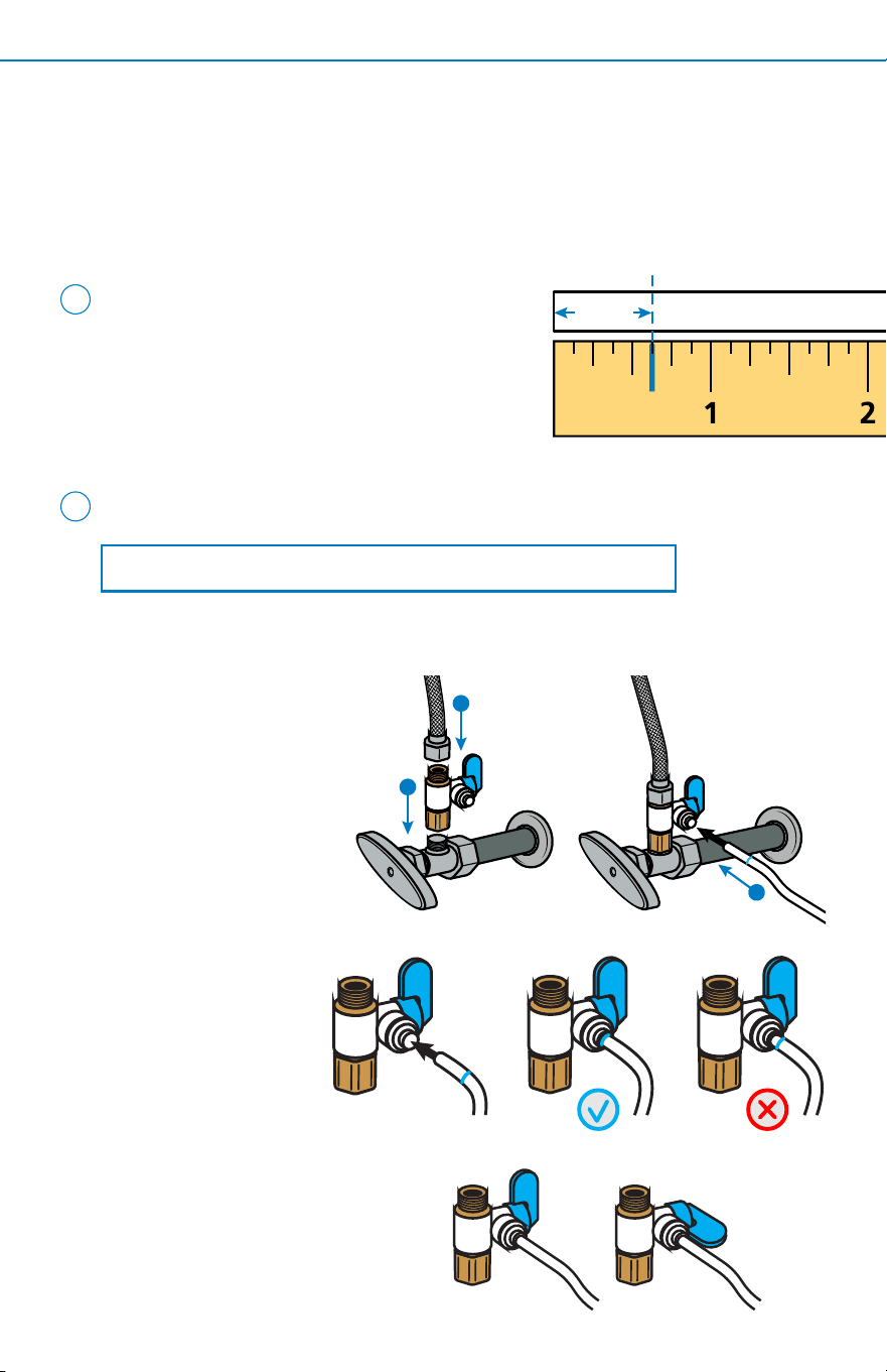
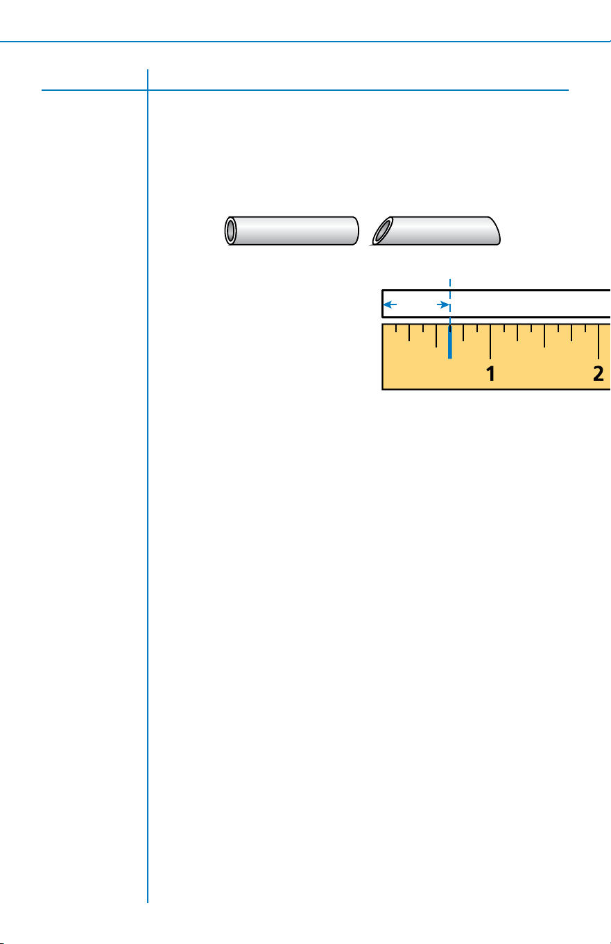
Prepare All Tubing Ends
A. If tubing needs to be cut to length, make
sure to use a sharp cutting device to
achieve a square cut.
B. Mark a line 0.625” from the end of each tube.
0.625”
Depth to insert tubing
(actual size)
B. Attach threaded ends
of easy-connect shut-
o valve to the cold
water line connection
on the shut-o valve.
Tighten with wrench.
Do not over tighten.
C. Reattach the cold water
line to the open
easy-connect shut-
o valve.
D. Push white tubing
into the open
quick connect
valve until the
mark on the
tubing is at or inside
the opening. Ensure
easy-connect shut-o
valve is in the open
position.
7
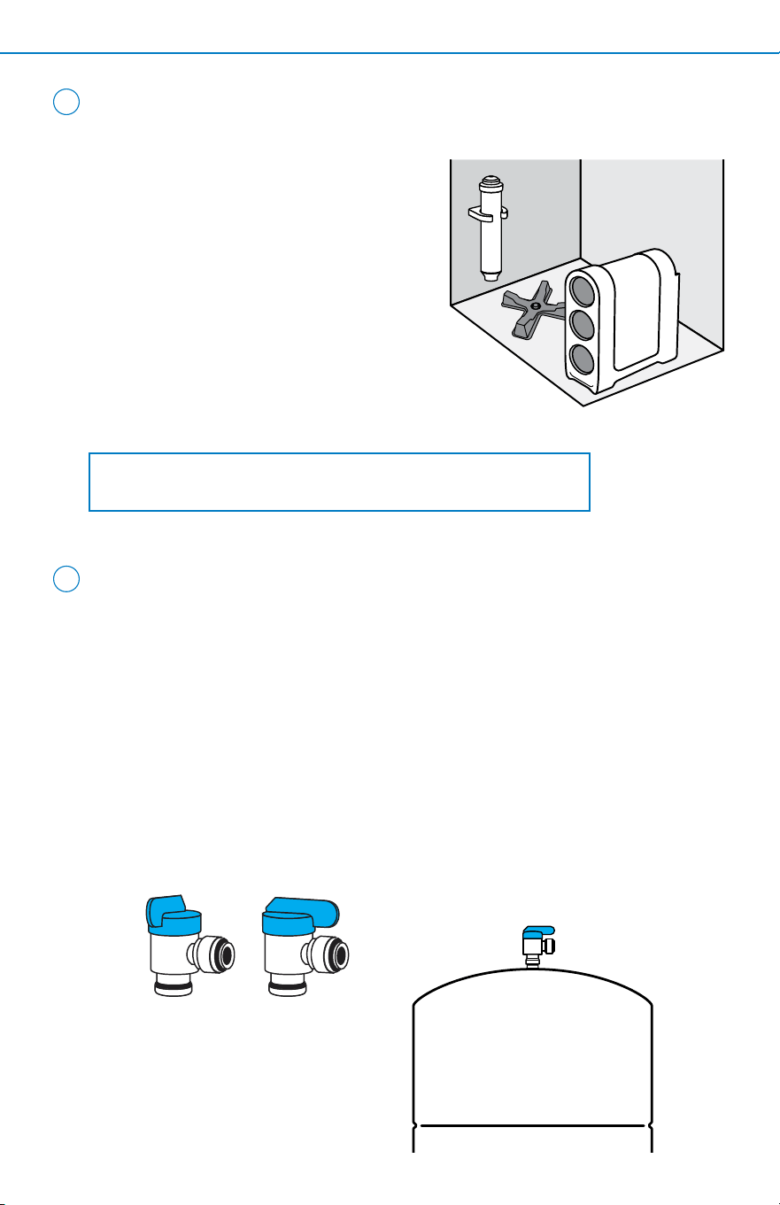
A. From the accessories box, nd the plumber's tape roll and water tank valve.
B. Wrap the plumber's tape around the threaded stainless steel connector
located on top of the water tank 4-5 times.
C. Screw the water tank valve onto the plumber's tape wrapped stainless
steel connector.
D. Hand tighten water tank valve until secure (be sure not to cross-thread or
over-tighten). After you have secured with hand tightening, tighten with
wrench a quarter turn to ensure secure t. Ensure water tank valve is
open, valve should be pointing towards the valve port.
TURN TO THE RIGHT
CLOSED OPEN
6
A. Place system manifold under the sink
in a place that will be easy to access
for scheduled lter changes. Do not
install lter cartridges at this time.
B. Using your screw driver and included
screw, install the remineralizer
bracket on your cabinet wall near the
system manifold. Insert remineralizer
cartridge with sticker text upward.
C. Finally, place water tank stand near
the system manifold.
NOTE: Placement of bracket must be close to system manifold
to ensure tube length needed for connection is sucient.
2
INSTALLATION STEPS6
Install System Manifold, Water Tank
Stand, and Remineralizer Bracket
Sanitize and Install Water Tank
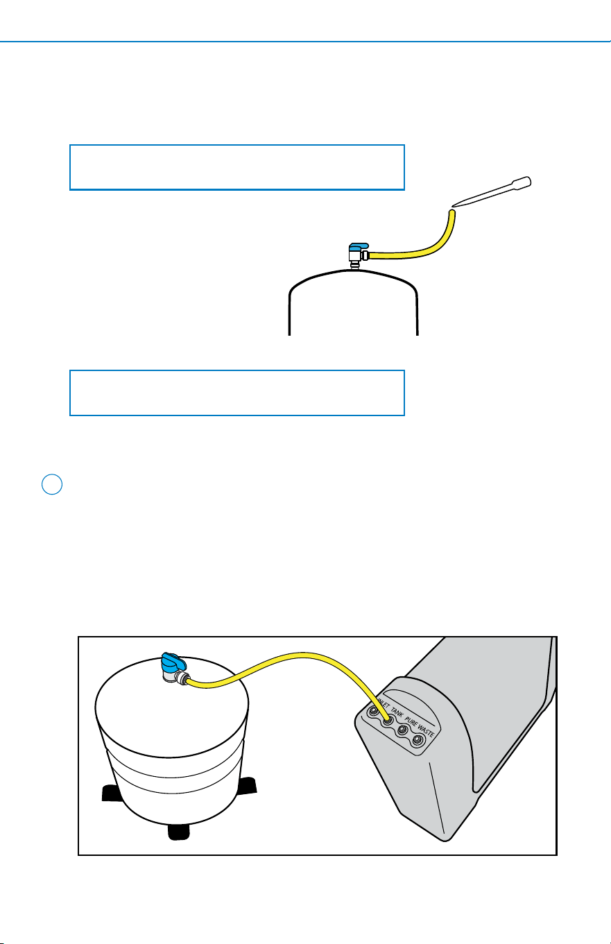
NOTE: Sanitation step will be completed during the
pressure test and ush step of the installation.
A. While keeping the yellow tubing upright, place water tank on the tank stand.
B. Connect water tank to the system manifold. Do so by connecting the
other end of the yellow tubing to the yellow inlet port on the backside
of the system manifold, labeled, 'TANK'.
8
E. Insert one end of the yellow tubing into the water tank valve. Using the
included eye dropper, add 3mL bleach into the open end of the attached
yellow tubing.
NOTE: Keep yellow tubing upright so that bleach
does not spill or leak.
INSTALLATION STEPS 7
Connect Water Tank to Manifold
2
INSTALLATION STEPS8
NOTES: Insert tubing completely until the mark on tubing
is at or inside the opening. A fully connected tube can be
inserted up to 0.625”.
Wet end of tubing for easier insertion.
Connect tubing to system in a way that does not
bend, crimp, or kink tubing as this will aect system
performance. If tubing is too long, measure and cut to
necessary length. If cutting the tubing due to excess length,
cut the tubing straight across, not at an angle.
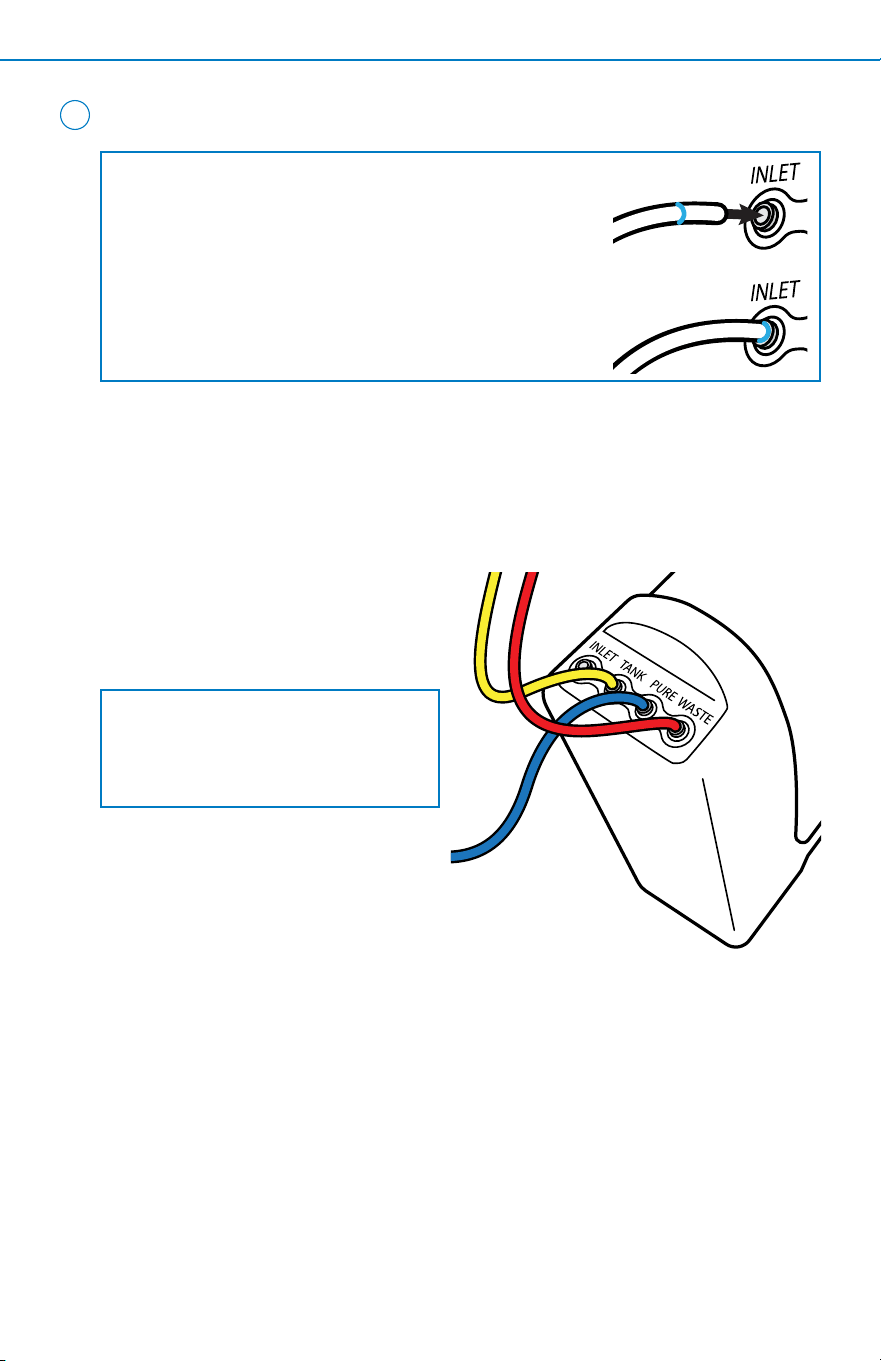
9
A. Push one end of 1/4” red tubing
into the drain saddle valve
tting. Push the other end into
the red inlet port on the back
of the system manifold, labeled
‘WASTE’.
Connect Tubing
Drain, Faucet, and Remineralizer Connect
B. Push 1/4” blue tubing coming
from faucet into the bottom end
of the remineralizer port.
C. Locate the blue tubing piece
included in the installation kit
and connect to the top port of
the remineralizer. Connect open
end of blue tubing coming from
the remineralizer into the blue
inlet port on the back of the
system manifold labeled, 'PURE'.
NOTE: If you are installing an air gap
adapter, do so at this time. Please
consult the manufacturer’s Owner’s
Manual for installation steps.
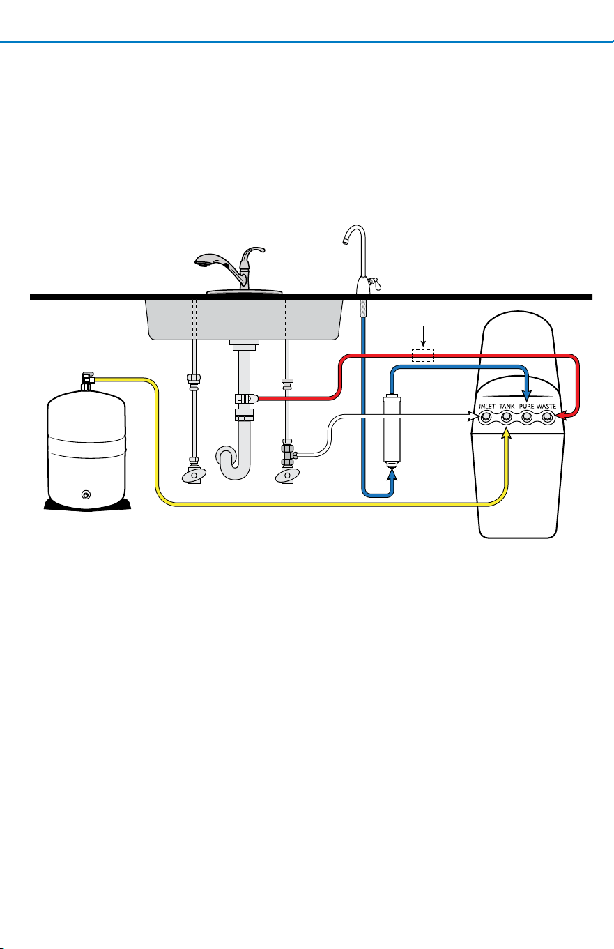
INSTALLATION STEPS 9
HOT COLD
*INSTALL AIR GAP
*Properly install air gap to comply with local codes. Air gap must be two pipe diameters or 1 inch (25mm), whichever is larger.
Easy-Connect Shut-O Valve Connect
A. Locate the white tubing, connect to the easy-connect shut-o valve, and
push into the white inlet port on the back of the system manifold, labeled,
‘INLET.’
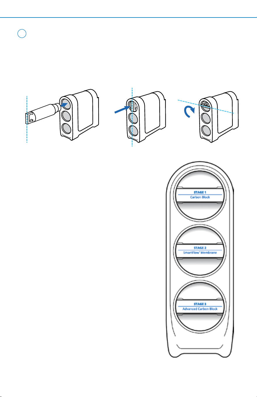
10
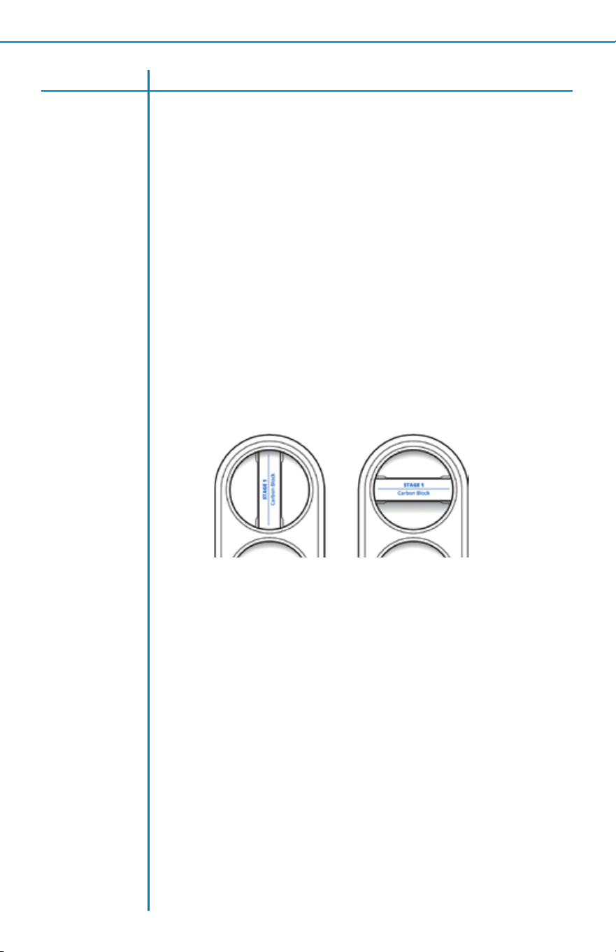
A. Insert each lter cartridge into its designated location in the system
manifold by turning to the right. Ensure lter cartridge handle is vertical
to the system manifold before inserting. The guides on each lter will
ensure proper alignment within the system manifold.
Insert
Handle
Vertically
Push in
Completely
Lock in
Horizontally
2
INSTALLATION STEPS10
Insert Filter Cartridges
B. Once the lter is engaged, push the lter
fully in while rotating 90 degrees to the
right. Continue this step for each lter.
· Top lter: Carbon Block
· Middle lter: SmartFlow
®
Membrane
· Bottom lter: Advanced Carbon Block
11
A. Turn o dedicated faucet.
B. Turn on COLD water supply valve.
C. Turn on kitchen faucet to release air from pipes. Once water is owing
normally, turn o kitchen faucet.
D. Within approximately two hours, the water tank will ll. Carefully inspect
all connections and ttings for leaks.
E. After ensuring all connections and ttings are secured, turn on the
dedicated faucet and let water ush until the tank empties and the ow
from the faucet slows to almost nothing. Close the faucet, wait two more
hours for the tank to ll again, and empty the tank. Repeat this step two
more times.
NOTE: After initial system ush, it will take 1-3 hours for the water tank to ll.
NOTE: Water ow rate will be slow during initial ush. A bubbling noise can be
expected. Do not drink the ushed water.
INSTALLATION STEPS 11
Pressure Test, Check for Leaks, and Flush
F. Once you have emptied three tanks of water, close all faucets and rell
for regular use.

2
CARE & SAFEGUARDS12
Care
To clean the system manifold and tank, wipe exterior with a damp cloth. Do not
use any strong or abrasive cleaning agent or solvent cleaner.
NOTICE
Safeguards
• If you experience a tubing connection leak, shut o cold water, disconnect
and re-set the tube.
• Do not install this system where the line pressure may exceed 80 psi. The
operating pressure range for this system is between 40-80 psi.
• Install on COLD water lines only (40°F-100°F).
• It is recommended that your system be installed inside and out of direct
sunlight. The system must be protected from both direct sunlight and
freezing temperatures.
• System and installation shall comply with applicable state and local laws.
• Do not operate without the lters installed.
• Do not use with water that is microbiologically unsafe or of unknown water
quality without adequate disinfection before or after the system.
• Systems certied for cyst reduction may be used on disinfected waters that
may contain lterable cysts.
• This reverse osmosis system contains a replaceable treatment component
that iscritical for the eective reduction of total dissolved solids. It is
recommended to periodically test this reverse osmosis system to verify it is
performing properly.
• This reverse osmosis system contains a replaceable component critical
to the eciency of the system. Replacement of the reverse osmosis
component should bewith one of identical specications, as dened
by the manufacturer, to ensure the same eciency and contaminant
reduction performance.
• This system has been tested and certied for Nitrate/Nitrite reduction
according to NSF/ANSI Standard 58. Proper maintenance is required to keep
the system functioning according to specications. It is recommended you
check your water every 3-4 months. Nitrate/Nitrite test included, see test kit
for sampling instructions.

CARE & SAFEGUARDS 13
Specications
Eciency rating is the percentage
of the inuent water to the system
that is available to the user as
reverse osmosis treated water.
This measurement is taken under
operation conditions that approximate
typical daily usage. The system’s
eciency rating was veried by testing
in accordance with Section 6.8 found
in NSF/ANSI 58.
Recovery rating is the percentage of
the inuent water to the membrane
portion of the system that is available
to the user as reverse osmosis treated
water when the system is operated
without a water tank or when the
water tank is bypassed.The system’s
recovery rating was veried by testing
in accordance with Section 6.8 found
in NSF/ANSI 58.
Because the performance of a
reverse osmosis membrane is
highly dependent upon pressure,
temperature, and Total Dissolved
Solids (TDS), the following should be
used for comparison only.
Lower temperatures are directly
proportional to slower ow rate. The
reverse osmosis system should not be
installed in a location susceptible to
freezing. Incoming water temperature
should not exceed 100°F (38°C). The
more TDS in the supply water, the
more lter time required. Incoming
TDS should not exceed 1000 ppm.
Higher water pressure enables a
higher ow rate. Pressure must be
at or above 40 psi for proper system
operation. You may consider installing
a booster pump if your pressure is
below 40 psi.
Flow rate and output are determined
by the following factors:
1. Incoming water temperature
2. Total dissolved solids (TDS) present
in supply water
3. Incoming water pressure
4. Tank size and amount of water in
the tank
Do not use the system on microbiologically
unsafe water, or water of unknown
quality without adequate disinfection
before or after the system. This system
is certied for cyst reduction and may
be used on disinfected water that may
contain lterable cysts.
Installations in The Commonwealth of
Massachusetts: The Commonwealth of
Massachusetts requires installation be
performed by a licensed plumber and
does not permit the use of saddle
valves. Plumbing code 248—CMR of the
Commonwealth of Massachusetts must
be followed in these cases.
AQ-SFRO2
Replacement cartridges AQ-SFRO-S1S3,
AQ-SFRO-S2, and AQ-SFRO-REMIN
Membrane TDS reduction: 89.6% minimum
Membrane TDS reduction: 96.4%+ average
Max TDS: 1000 ppm
Max water hardness @ 6.9 pH: 10 gpg (2.64 gpL)
Max chlorine in water: 3 ppm
Supply water pH limits: 4-10
Storage tank capacity: 2.5 gallons (9.46 liters)
Supply water pressure limits: 40-80 psi
(275-551 kPa)
Supply water temperature limit: 40-100°F
(4-38°C)

2
CARE & SAFEGUARDS14
Arsenic Facts
Arsenic (As) is a naturally occuring
contaminant found in many ground
waters. Arsenic in water has no color,
taste or odor. It is measured by a
laboratory test. Public water utilities
must have their water tested for
arsenic. You can get the results from
your water utility. If you have your own
well, you can have the water tested.
The local health department or the
state environmental health agency
can provide a list of certied labs.
Information about arsenic in water
can be found on the internet at the
U.S. Environmental Protection Agency
website:
epa.gov/safewater/arsenic
There are two forms of arsenic:
pentavalent arsenic (As(V), As(+5), and
arsenate) and trivalent arsenic (also
called As(III), As(+3), and arsenite).
Although both forms of arsenic are
potentially harmful to human health,
trivalent arsenic is considered more
harmful than pentavalent arsenic. In
water, arsenic may be pentavalent,
trivalent, or a combination of both.
Special sampling procedures are
needed for a lab to determine what
type and how much of each type of
arsenic is in the water. Check with the
This system has been tested for the treatment of water containing pentavalent
arsenic (also known as As(V), As(+5), or arsenate) at concentrations of 0.05
mg/L or less. This system reduces pentavalent arsenic, but may not remove
other forms of arsenic. This system is to be used on water supplies containing
a detectable free chlorine residual at the system inlet or on water supplies
that have been demonstrated to contain only 50 ppb (0.050 mg/L) pentavalent
arsenic. Treatment with chloramine (combined chlorine) is not sucient to
ensure complete conversion of trivalent arsenic to pentavalent arsenic. Please
see the Arsenic Facts section below for further information.
labs in your area to see if they can
provide this type of service.
If you get your water from a public
water utility, contact the utility to
nd out if free chlorine or combined
chlorine is used in the water system.
The AQ-SFRO2 system is designed
to reduce pentavalent arsenic only.
It will not convert trivalent arsenic
to pentavalent arsenic. This System
was tested in a lab. Under testing
conditions, the system reduced [0.050
mg/L (ppm)] pentavalent arsenic to
0.010 mg/L (ppm) (the USEPA standard
for drinking water) or less. The removal
performance of pentavalent arsenic
of the system may be limited due to
water quality conditions (i.e. iron-
containing water or other water quality
conditions). Have your treated water
tested for arsenic to check whether the
system is working properly.
The SmartFlow
®
Membrane of the
AQ-SFRO2 system must be replaced
every 12 months to ensure the system
will continue to remove pentavalent
arsenic. Information regarding
component identication and places
to purchase replacement are listed in
the manual.

FILTER REPLACEMENTS 15
Carbon Block and Advanced Carbon Block
Replace every 6 months*
The Carbon and Advanced Carbon Blocks are replaceable activated carbon
cartridges located in Stages 1 and 3. It is recommended to replace these
cartridges at least every 6 months. You may need to replace more often with high
water usage or high sediment levels. Timely replacement of these cartridges will
protect the RO Membrane from high levels of chlorine and/or sediment. As these
lters build up with sediment, you may notice slower water output.
Scan here to view the Carbon Block and
Advanced Carbon Block replacement manual.
SmartFlow
®
Membrane
Replace every 12 months*
The SmartFlow
®
Membrane is located in Stage 2. This membrane reduces the
dissolved solids and organic matter. Most municipally treated water has a 7.0-7.5
pH. In this case you would need to replace your SmartFlow
®
Membrane every 12
months. Membrane life depends on pH and supply water hardness. Higher pH
shortens membrane life by causing pin-hole leaks. When output, water quality,
and production rate decrease, it is time to replace the lter.
*Filter life depends on water usage and water supply quality.
Scan here to view the SmartFlow
®
Membrane replacement manual.
Remineralizer
Replace every 6 months*
The Remineralizer is located outside of the manifold. It is recommended
to replace this cartridge every 6 months.
Scan here to view the
Remineralizer replacement manual.
2
PERFORMANCE & CERTIFICATIONS16
Model Replacements Recovery Rating
AQ-SFRO2
AQ-SFRO-S1S3
AQ-SFRO-S2
AQ-SFRO-REMIN
42.8%
Operating Temp. Range Eciency Rating Daily Production
40-100° F
4-38° C
27.4% 25.7 gpd
Manufactured by: Aquasana, Inc.
4343 Hamilton Road · Groveport, OH 43125
866-662-6885
System tested and certied by WQA to NSF/ANSI Standards 42, 53, 58, 401, and CSA B483.1 for
the reduction of the claims specied on the Performance Data Sheet and at www.WQA.org.
This system conforms to NSF/ANSI 53 for VOC reduction. See Performance Data Sheet for
individual contaminants and reduction performance. All claims are veried and subastantiated
by test data.
For the full list of contaminants ltered, scan to view the
AQ-SFRO2 Performance Data Sheet on Aquasana.com.
In order to maintain the NSF/ANSI 58 certication of this product, the drain line installation must comply with the
standard requirements of a vertical air gap of two pipe diameters or 25 mm (1 in), whichever is larger, or an air gap
faucet that is tested and certied against NSF/ANSI 58 must be included.
TROUBLESHOOTING GUIDE 17
Issue Resolution
Water Leak/
Drip From
Tubing or
Dedicated
Faucet
Water Leak/
Drip From
Water Tank
Valve
Step 1: Turn o the cold water valve underneath the sink and depressurize
the system by opening the faucet and releasing all the water.
Step 2: Ensure color-coded tubing is installed into the correct placement
on the system.
Step 3: If cutting the tubing due to excess length, cut the tubing straight
across, not at an angle.
Step 1: Check to make sure the tubing is fully inserted into the port.
Step 2: Using a wrench, tighten the valve located on the top of the water tank.
Correct Incorrect
0.625”
Depth to insert tubing
(actual size)
Slow Flow
Step 1: Ensure water is owing from the faucet. If water is owing, close
faucet and come back in 1-2 hours to re-check pressure. This will allow
enough time for the tank to be lled.
Step 2: Check the feed temperature, pressure, and TDS to ensure inlet
water conditions for proper operation are met.
Step 3: If it has been over six months since changing the Carbon Block
and/or Advanced Carbon Block, we recommend changing these lters. We
advise replacing the Carbon Block rst, then the Advanced Carbon Block if
the issue is not resolved
NOTE: The best ow rate will be 0.7 GPM when the tank is completely
full. The ow rate may slow as the water is depleted from the tank.
Step 4: Check and make sure the
tubing is fully inserted into the
system manifold until tubing can
no longer be pushed. A loose
connection can cause a leak at the
inlet/outlet.
Step 5: Once all tubing is installed
and the system is re-connected, turn
the water valve back on and check
for leaks.
Step 6: Make sure that the
cartridges are in the locked
position. They should be rotated fully clockwise until the handles are
horizontal (see illustration on page 18).
NOTE: If the unit is still leaking after checking the cartridges and tube
connections, shut o the cold water valve to the RO unit and contact
Customer Support at 866-662-6885.
If you are experiencing a leak or drip from the manifold, do not attempt
to dissemble. Turn cold water valve o and contact Customer Support
at 866-662-6885.
2
TROUBLESHOOTING GUIDE18
How do I know I connected the tubing all the way?
The tubing must be inserted 0.625". We recommended making a mark
at 0.625" from the end of the tube and then inserting the tube all the
way up to that point. Since leaks may not appear immediately after
installing, we recommend re-checking for leaks an hour after the tank
has lled and continuing to check for leaks periodically.
Can I install the cartridges in the wrong stage?
No, the guides to help with insertion can only t in their correct
cartridge slot.
How do I know I connected the lter correctly?
The cartridge handle should be horizontal and handle labeling should
be right side up.
How do I know the system is ltering my drinking water?
The best way to know if you're drinking ltered water is to purchase a
water quality test kit and a contaminant reduction test.
Or, have a licensed professional test your drinking water.
Why is my water grey or black?
Carbon "nes" can be present in your water when new lters are rst
installed and will go away after the ushing cycle. Ensure you ushed your
system for the adequate time on page 11.
INSERT
VERTICALLY
LOCK IN
HORIZONTALLY
Common
Questions
Issue Resolution

TROUBLESHOOTING GUIDE 19
Common
Questions
Issue Resolution
Why is my ow rate slow?
The inlet water pressure will aect your ow rate. While this system has
a 0.7 gpm ow rate, if your ow rate is less than that, you can consider
purchasing a booster pump.
Do I need to depressurize my system before replacing the lters?
Yes, you must depressurize the system before replacing any of the
lters. Failure to release pressure can result in permanent system
damage. Do so by closing the inlet tee valve and closing the water
tank valve. Release the pressure by turning on the dedicated faucet
until water stops owing. Once water has stopped owing from
the dedicated faucet, turn the faucet o and proceed with lter
replacement.
I have an existing dedicated faucet. Can I use that with this
system?
Yes, as long as the faucet is compatible with a 1/4” tubing.
I have an existing air gap dedicated faucet. Can I use that with this
system?
Yes, as long as the faucet is compatible with a 1/4” tubing. There is no
need for a separate air gap adapter installed on the drain line.
How do I dispose of the lter cartridges?
You can take the entire lter cartridge and put it in the trash. While
it can’t be recycled, it is designed with minimal components to help
reduce waste.
When handling the lter cartridges, is it suppose to sound like
something is moving around inside of the cartridge?
Yes, you may hear a noise inside of the lter cartridges, which is the
carbon block media. Once the lter cartridges are installed in the
manifold, you will not hear this noise.

SmartFlow
®
Reverse Osmosis
2-Year Limited Warranty
WHO IS COVERED
AQUASANA AND ITS SUPPLIERS, (herein collectively referred
to as “Manufacturer”) warrants to the original owner who
purchased and installed the system (hereinafter “Owner”).
Registration of the product is not required to receive warranty
coverage as specied in this document. If you purchased from
an Aquasana-authorized reseller or dealer, proof of purchase
is required.
WHAT IS COVERED
This Warranty covers defects in materials or workmanship
during the limited Warranty period of your of your Aquasana
Water Filtration System including sub-components purchased
with original system (may or may not include faucet and
ttings), except as provided below. The water lter is
warranted only when it is installed, operated and maintained
in accordance with the instructions accompanying the water
lter found on Aquasana.com. A water lter should be installed
in such a manner that, if the system or any connection thereto
should leak, the resulting ow of water will not cause damage
to the area in which it is installed. For detailed instructions
read the manual accompanying the water lter and review
drawings in the manual.
FOR HOW LONG
This Warranty runs for 12 months (365 days) from the date of
purchase by a consumer (hereinafter “Warranty Period”). No
Warranty coverage will be provided if the claimant is unable
to provide proof of purchase from an authorized Aquasana
reseller. Estimated lifespan of products is for information only
and is based on usage approximations. Water conditions and
use rates may limit the functional lifespan of your lter. This
Limited Warranty does not extend to the full estimated life
span of the system.
WHAT AQUASANA WILL DO
1. If necessary, the Manufacturer will provide a replacement
that fullls the remaining estimated lifespan/capacity of
your original purchase and send it to you with installation
instructions. If industry standards, product improvements
or product obsolescence prohibit Manufacturer from
furnishing an identical model replacement water lter under
this Warranty, the Owner will be furnished with a new water
lter of comparable remaining capacity and functionality;
however, the Owner will be charged for the additional value
of the item(s) which Manufacturer has incorporated in
the replacement water lter. The Warranty period for any
replacement will run for the balance of the original 365 days.
2. Component Part – If any component part proves to
Manufacturer’s satisfaction to be defective in material or
workmanship within the Warranty period listed on the data
plate label, the Manufacturer will furnish the Owner with a
replacement for the defective part(s).
3. Return of Defective Water Filter and Component Parts –
Manufacturer reserves the right to examine the alleged
defect in the water lter or component part(s), and it
will be the Owner’s obligation to return the water lter
and/or component part(s) to the Manufacturer at the
Manufacturers request.
a. When returning a water lter, it must include all
component parts.
b. When returning component part(s), they must be
individually tagged and identied with the water lter’s
model number, date of purchase, and date of installation.
WHAT IS NOT COVERED
1. This Warranty does not cover systems or components that
were not installed in compliance with the instructions or
that have been abused or operated incorrectly.
2. This Warranty does not provide routine replacement
lter cartridges which must be purchased separately and
replaced as indicated; replacement lter cartridges are
available only when the original cartridge supplied with
the system is damaged or defective when purchased.
This Warranty applies only to products purchased from
Aquasana or an Aquasana-authorized reseller or dealer.
3. Except when specically prohibited by the applicable state
law, the Limited Warranty stated herein is in lieu of any
and all warranties, express or implied (whether written or
oral), including, but not limited to, the implied warranties of
merchantability and tness for a particular purpose.
4. Except when specically prohibited by the applicable state
law, the Manufacturer shall not be liable for any incidental,
consequential, special, or contingent damages or expenses,
arising, directly or indirectly, from any defect in the water
lter of the use of the water lter.
5. Manufacturer shall not be liable for any incidental,
consequential, special, punitive, or contingent damages or
expenses, arising, directly or indirectly, from any defect in
the water lter or the use of the water lter, including but
not limited to water damage.
6. Manufacturer shall not be liable for any water damage
arising, directly or indirectly, from any defect in the water
lter or component part(s) or from its use.
7. Manufacturer shall not be liable for any damage or product
failures caused by any of the following:
• The water lter or any of its component parts have been
subject to misuse, alteration, neglect or accident.
• The water lter has not been installed in accordance with
the applicable local plumbing and/or building code(s) and/
or regulations or in their absence.
• The water lter is not installed, operated and maintained
in accordance with the printed Manufacturer’s instructions,
including if the water lter has any additional aftermarket
equipment introduced into the sealed system not
approved by the manufacturer.
• The water lter is exposed to highly corrosive conditions.
• The water lter is not continuously supplied with potable water.
• The water lter is not operated within the factory
calibrated temperature limits.
• The water lter is installed in direct sunlight or exposed to
freezing temperatures.
• The water lter or any of its component parts fail due to
sediment build-up.
• Clogging due to purchaser’s failure to replace the lter
cartridges.
• Damage caused by re, ood or acts of God.
• Damage caused by over-pressurization in the water line.
8. Manufacturer shall not be liable for any claims related to
excessive noise, smell, or taste of water.
9. This Warranty does not cover damage caused by the use of
parts that are not genuine Aquasana parts. This includes,
but is not limited to replacement lters, faucets, and/or
diverter valves.
10. Except when specically prohibited by the applicable state
law, the Owner, and not the Manufacturer, shall be liable
for and shall pay for all charges for labor or other expenses
incurred in the removal, repair or replacement of the water
lter or any component part(s) claimed to be defective or
any expense incurred to remedy any defect in the product.
Such charges may include, but are not necessarily limited to:
a. All freight, shipping, handling and delivery costs of forwarding
a new water lter or replacement part(s) to the owner.
b. All costs necessary or incidental in removing the defective
water lter or component part(s) and installing a new
water lter or component part(s).
c. Any material required to complete, and/or permits
required for, installation of a new water lter or
replacement part(s), and
d. All costs necessary or incidental in returning the defective
water lter or component part(s) to a location designated
by the Manufacturer.
11. This warranty provides specic legal rights and limitations,
but you may have other rights under applicable state law.
HOW TO GET SERVICE
To receive service under this Warranty, you must contact Aqua-
sana (A. O. Smith Water Treatment (North America), Inc.) at
1-866-662-6885 or [email protected] within the Warran-
ty Period to describe the problem to a customer service rep-
resentative who will verify that the product is under Warranty
and determine whether a part or the system will be replaced
and whether you must send back the unit. You will be required
to provide both proof of purchase and proper installation.
HOW STATE LAW APPLIES
This Warranty gives you specic rights and you may have other
rights which vary from state to state. Some states do not allow
the exclusion or limitation of incidental or consequential
damages, so the above limitation or exclusion may not apply
to you.
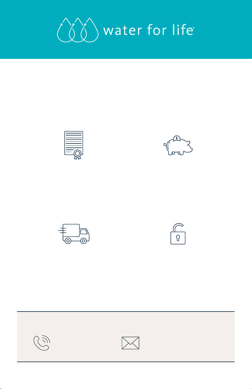
Protect your investment and save money with Water for Life
®
.
Our Water for Life
®
program helps you protect the investment you’ve made in
your family’s health with an extended limited warranty on your new ltration
system, a 15% discount on replacement lters, and free shipping.
* Exclusions apply. Limited Warranty details are available at aquasana.com. Benets are for the term of Water for Life membership.
Free Shipping
Replacements shipped to
you right when you need
them – at no extra cost.
Discounted
Replacements
The only way to lock
in a 15% discount on
replacement lters.
Extended
Limited Warranty
Our performance promise
to you – free replacement
parts when needed.
*
No Contract
Free to join and cancel
anytime – no long-term
commitment required.
CONTACT US TO LEARN MORE
866-275-2319

100385843
AQ-SFRO2-OM-20260211
Aquasana, Inc.
4343 S. Hamilton Road
Groveport, OH 43125
866-662-6885 USA
877-332-7873 Canada
www.aquasana.com
NEED HELP?
Give us a call at
866-662-6885 and
tell us what's going on.
LOVE IT?
Please let us know with a
review on Aquasana or
your retailer’s site.