1
Instruction Manual
PRINTED 1016 100276587
KEEP THIS MANUAL IN THE POCKET ON HEATER FOR FUTURE REFERENCE
WHENEVER MAINTENANCE ADJUSTMENT OR SERVICE IS REQUIRED.
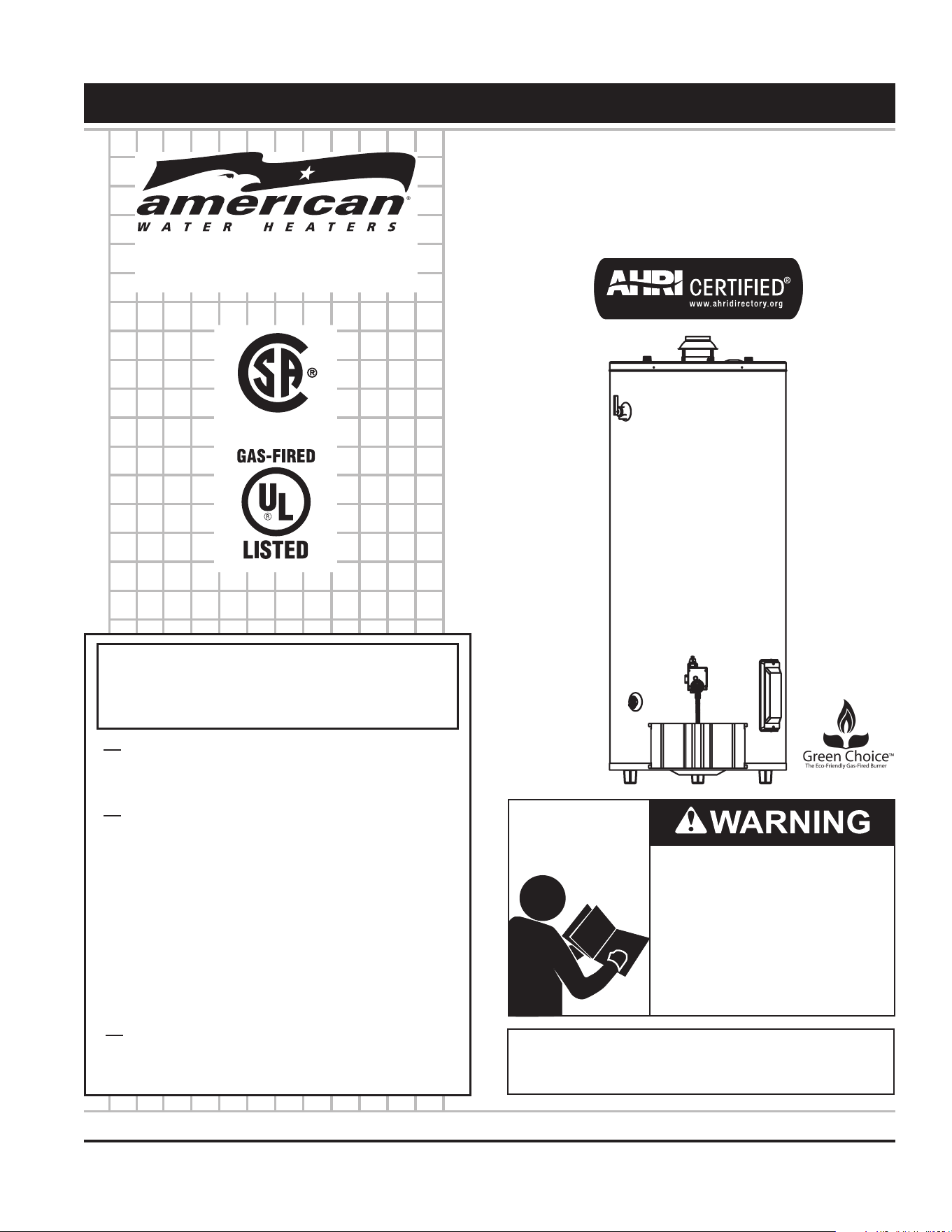
ULTRA LOW NOX COMMERCIAL GAS WATER HEATERS
• For Your Safety •
AN ODORANT IS ADDED TO THE GAS USED
BY THIS WATER HEATER.
MODELS
BCN375T754NV/BCN3100T754NV
Series 100
INSTALLATION - OPERATION - SERVICE
- MAINTENANCE - LIMITED WARRANTY
PLACE THESE INSTRUCTIONS ADJACENT TO HEATER AND NOTIFY OWNER TO KEEP FOR FUTURE REFERENCE.
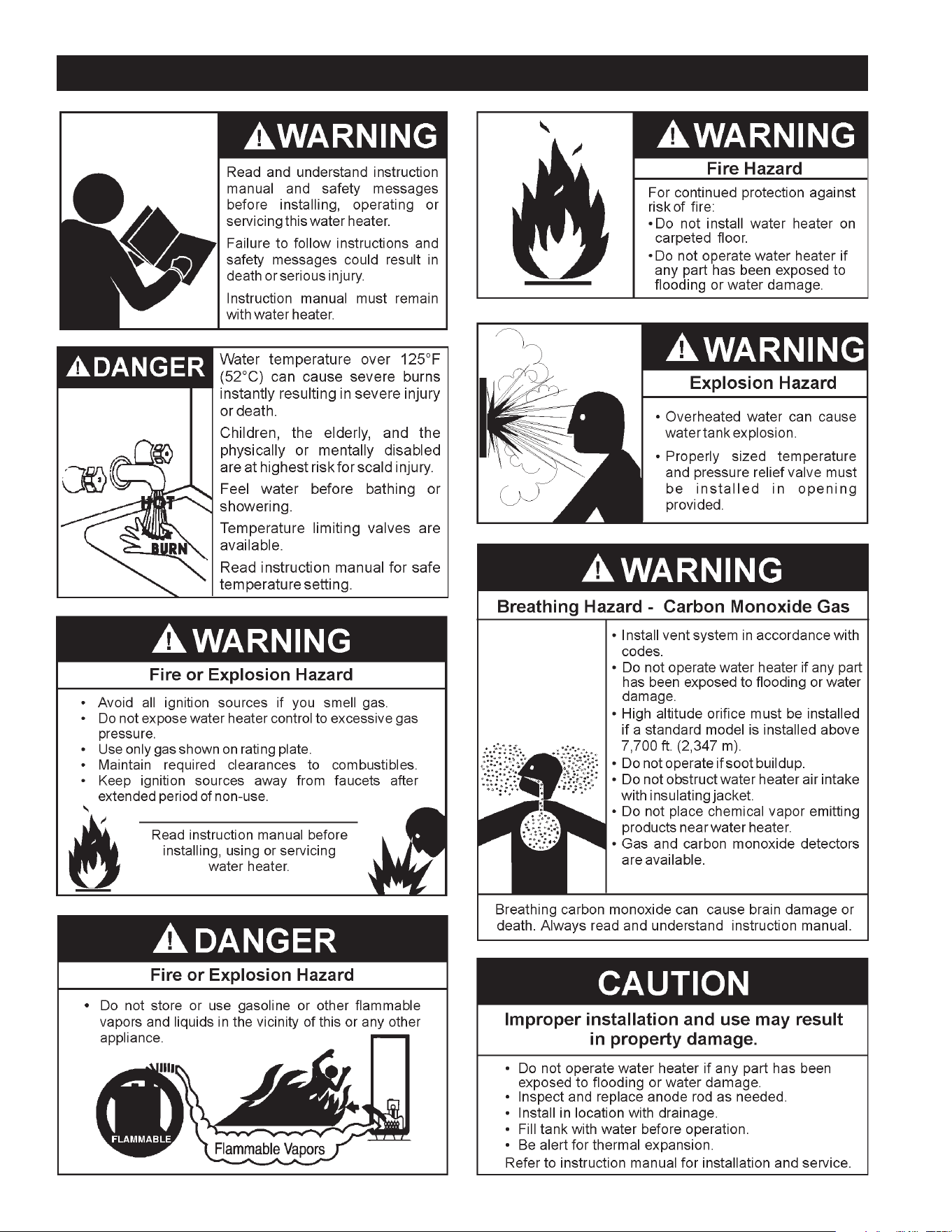
Read and understand this instruction
manual and the safety messages
herein before installing, operating or
servicing this water heater.
Failure to follow these instructions and
safety messages could result in death
or serious injury.
This manual must remain with the
water heater.
Low Lead Content
WARNING: If the information in these
instructions is not followed exactly, a fire
or explosion may result causing property
damage, personal injury or death.
Do not store or use gasoline or other
flammable vapors and liquids in the
vicinity of this or any other appliance.
WHAT TO DO IF YOU SMELL GAS:
Do not try to light any appliance.
Do not touch any electrical switch; do
not use any phone in your building.
Immediately call your gas supplier
from a neighbor’s phone. Follow the
gas supplier’s instructions.
If you cannot reach your gas supplier,
call the fire department.
Installation and service must be
performed by a qualified installer,
service agency or the gas supplier.
•
•
•
•
www.americanwaterheater.com
American Water Heater
Johnson City, TN 37605

2
SAFE INSTALLATION, USE AND SERVICE...................... 3
APPROVALS ...................................................................... 3
GENERAL SAFETY INFORMATION .................................. 4
INTRODUCTION ................................................................ 5
Abbreviations Used ..................................................... 5
QualiedInstallerorServiceAgency........................... 5
PreparingfortheNewInstallation ............................... 5
INSTALLATION CONSIDERATIONS ................................. 6
RoughInDimensions .................................................. 6
Thermometers ............................................................. 7
FactstoConsiderAboutTheLocation ........................ 7
HighAltitude ................................................................ 8
Clearances .................................................................. 8
Insulation Blankets ...................................................... 9
Hard Water .................................................................. 9
CirculationPumps ....................................................... 9
INSTALLATION REQUIREMENTS .................................. 10
GasSupplySystems ................................................. 10
GasPressureRequirements ..................................... 10
SupplyGasRegulator ............................................... 10
MixingValves ............................................................ 10
WaterPiping .............................................................. 11
ClosedWaterSystems .............................................. 11
ThermalExpansion ................................................... 11
Temperature-PressureReliefValve ......................... 11
FillingtheWaterHeater ............................................. 12
AirRequirements....................................................... 12
UnconnedSpace ..................................................... 13
ConnedSpace ......................................................... 13
FreshAirOpeningsforConnedSpaces .................. 13
OutdoorAirThroughTwoOpenings .......................... 13
OutdoorAirThroughOneOpening ........................... 13
OutdoorAirThroughTwoHorizontalDucts ............... 14
OutdoorAirThroughTwoVerticalDucts ................... 14
AirFromOtherIndoorSpaces .................................. 14
Venting ...................................................................... 14
GasPiping ................................................................. 16
SedimentTraps ......................................................... 17
LIGHTING & OPERATING INSTRUCTIONS ................... 18
TEMPERATURE REGULATION ...................................... 19
FOR YOUR INFORMATION ............................................. 19
Start Up Conditions ................................................... 19
Operational Conditions .............................................. 20
PERIODIC MAINTENANCE ............................................. 21
VentingSystemInspection ........................................ 21
BurnerInspection ...................................................... 21
BurnerCleaning ........................................................ 21
Housekeeping ........................................................... 21
AnodeRodInspection ............................................... 22
Temperature-PressureReliefValveTest ................... 22
RECOMMENDED PROCEDURE FOR PERIODIC
REMOVAL OF LIME DEPOSITS FROM TANK
TYPE COMMERCIAL WATER HEATERS ........................ 22
DelimingSolvents...................................................... 23
TankCleanoutProcedure .......................................... 23
DelimingUsingFlo-JugMethod ................................ 23
DrainingandFlushing ............................................... 24
Service ...................................................................... 24
LEAKAGE CHECKPOINTS .............................................. 25
TROUBLESHOOTING GUIDELINES ............................... 26
WATER PIPING DIAGRAMS ............................................ 27
NOTES ............................................................................. 33
WARRANTY .....................................................................35
TABLE OF CONTENTS
3
SAFE INSTALLATION, USE AND SERVICE
Theproperinstallation,useandservicingofthiswaterheaterisextremelyimportanttoyoursafetyandthesafetyofothers.
Manysafety-relatedmessagesandinstructionshavebeenprovidedinthismanualandonyourownwaterheatertowarnyouand
othersofapotentialinjuryhazard.Readandobeyallsafetymessagesandinstructionsthroughoutthismanual.Itisveryimportant
thatthemeaningofeachsafetymessageisunderstoodbyyouandotherswhoinstall,use,orservicethiswaterheater.
Allsafetymessageswillgenerallytellyouaboutthetypeofhazard,whatcanhappenifyoudonotfollowthesafetymessage,and
howtoavoidtheriskofinjury.
DANGER
WARNING
CAUTION
CAUTION
DANGER indicates an imminently
hazardous situation which, if not avoided,
will result in injury or death.
This is the safety alert symbol. It is used to alert you to
potential personal injury hazards. Obey all safety
messages that follow this symbol to avoid possible
injury or death.
WARNING indicates a potentially hazardous
situation which, if not avoided, could result
in injury or death.
CAUTION indicates a potentially hazardous
situation which, if not avoided, could result in
minor or moderate injury.
CAUTION used without the safety alert
symbol indicates a potentially hazardous
situation which, if not avoided, could result in
property damage.
APPROVALS
Low Lead Content
4
GENERAL SAFETY INFORMATION

5
ThankYouforpurchasingthiswaterheater.Properlyinstalledand
maintained,itshouldgiveyouyearsoftroublefreeservice.
ABBREVIATIONS USED
AbbreviationsFoundInThisInstructionManual:
• UL-UnderwritersLaboratoriesInc.
• ANSI-AmericanNationalStandardsInstitute
• NFPA-NationalFireProtectionAssociation
• ASME-AmericanSocietyofMechanicalEngineers
• AHRI-Air-Conditioning,HeatingandRefrigerationInstitute
• CAN-Canada
• EPACT-EnergyPolicyAct
• CSA-CanadianStandardsAssociation
This gas-fired water heater is design certified by Underwriters
LaboratoriesInc.underAmericanNationalStandard/CSAStandard
forGasWaterHeatersANSIZ21.10.3•CSA4.3(currentedition).
QUALIFIED INSTALLER OR SERVICE AGENCY
Installationandserviceofthiswaterheaterrequiresabilityequivalent
tothatofaQualiedAgency(asdenedbyANSIbelow)intheeld
involved. Installation skills such as plumbing, air supply, venting,
gassupplyandelectricalsupplyarerequiredinadditiontoelectrical
testingskillswhenperformingservice.
ANSIZ223.12006Sec.3.3.83:“QualiedAgency”-“Anyindividual,
rm, corporation or company that either in person or through a
representativeisengagedinandisresponsiblefor(a)theinstallation,
testingorreplacementofgaspipingor(b)theconnection,installation,
testing, repair or servicing of appliances and equipment; that is
experiencedinsuchwork;thatisfamiliarwithallprecautionsrequired;
and that has complied with all the requirements of the authority
havingjurisdiction.”
Ifyouarenotqualied(asdenedbyANSIabove)andlicensedor
certiedasrequiredbytheauthorityhavingjurisdictiontoperforma
giventaskdonotattempttoperformanyoftheproceduresdescribed
in this manual. If you do not understand the instructions given in
thismanual donot attemptto performany proceduresoutlined in
thismanual.
PREPARING FOR THE INSTALLATION
1. ReadtheGeneralSafetyInformationsection,page4ofthis
manual first and then the entire manual carefully. If you
don’tfollowthesafetyrules,thewaterheaterwillnotoperate
properly.ItcouldcauseDE ATH,SERIOUSBODILYINJURY
AND/ORPROPERTYDAMAGE.
This manual containsinstructions for theinstallation,
operation,andmaintenanceofthegas-firedwaterheater.It
alsocontainswarningsthroughoutthemanualthatyoumust
readandbeawareof.Allwarningsandallinstructionsare
essentialtotheproperoperationofthewaterheaterandyour
safety.Sincewecannotputeverythingonthefirstfewpages,
READ THE ENTIRE MANUAL BEFORE ATTEMPTING TO
INSTALL OR OPERATE THE WATER HEATER.
2.The installation must conform with these instructions and
thelocalcodeauthorityhavingjurisdiction.Intheabsence
oflocalcodes,theinstallationmustcomplywiththecurrent
editions of the National Fuel Gas Code, ANSI Z223.1/
NFPA54orCAN/CSA-B149.1theNaturalGasandPropane
Installation Code. All documents are available from the
CanadianStandardsAssociation,8501EastPleasantValley
Road, Cleveland, OH 44131. NFPAdocuments are also
available from the National Fire Protection Association, 1
BatterymarchPark,Quincy,MA02269.
3.Ifafter readingthismanual youhaveanyquestions ordo
notunderstandanyportionoftheinstructions,callthelocal
gasutilityorthemanufacturerwhosenameappearsonthe
ratingplate.
4.Carefully plan the place where you are going to put the
water heater. Correct combustion, vent action,and vent
pipeinstallationareveryimportantinpreventingdeathfrom
possiblecarbonmonoxidepoisoningandfires,seeFigures
3 and 7.
Examinethelocationtoensurethewaterheatercomplieswith
theFacttoConsiderAboutTheLocationsectioninthismanual.
5.ForCaliforniainstallationthiswaterheatermustbebraced,
anchored, or strapped to avoid falling or moving during
an earthquake. See instructions for correctinstallation
procedures.InstructionsmaybeobtainedfromCalifornia
Office of the State Architect, 400 P Street, Sacramento,
CA 95814.
6.MassachusettsCoderequiresthiswaterheatertobeinstalled
in accordance with Massachusetts 248-CMR 2.00: State
PlumbingCodeand248-CMR5.00.
7.Complies with SCAQMD rule #1146.2 and districts having
equivalentNOxrequirements.
INTRODUCTION
6
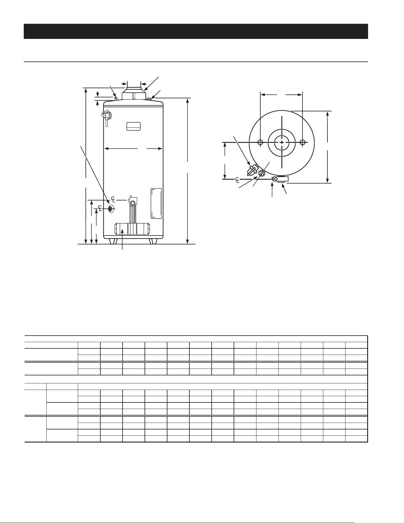
ROUGH IN DIMENSIONS
INSTALLATION CONSIDERATIONS
FIGURE 1.
K
HOT WATER
OUTLET
DRAIN
VALVE
HOT
COLD
TOP VIEW
L
GAS INLET
INSTALL IN ACCORDANCE WITH LOCAL CODES
DRAIN VALVE
K
COLD WATER
INLET
OUTER DOOR
(BURNER ASSEMBLY BEHIND)
DRAFT HOOD
F
H
J
B
D
A
E
M
G
TEMPERATURE
AND PRESSURE
RELIEF VALVE
C
WATER HEATER
CONTROL
TABLE 1.
Units ABCDEFGH JK
LM
Inches 70 1/2 66 1/2 30 15/16 27 3/4 15 3/16 415 3/4 16 1 1/41 1/4 1/211 15/16
CM 179.1 168.9 78.6 70.5 38.6 10.2 40.0 40.63.2 NPTNPT 30.3
Inches 62 1/165829 1/225 1/415 7/8 4 15 1/4 16 211/212 1/2
CM 157.6 147.3 74.9 64.1 40.3 10.2 38.7 40.65.1 NPTNPT 31.8
ModelINPUT RATE
°F 30 40 50 60 70 80 90 100 110 120 130 140
GPH 246 184 147 123105 92 82 74 67 61 57 53
°C 17 22 28 33 39 44 50 56 61 67 72 78
LPH 930 698 558 465399 349 310 279 254233 215 199
°F 30 40 50 60 70 80 90 100 110 120 130 140
GPH 243 182 146 121104 91 81 73 66 61 56 52
°C 17 22 28 33 39 44 50 56 61 67 72 78
LPH 919 689 551 459394 345 306 276 251230 212 197
* Recover rang based on 81% thermal efficiency
** Recover rang based on 80% thermal efficiency
Natural
DIMENSIONS
Model
BCN3100*
BCN375**
75,100 BTU/H
22 kW
75,100 BTU/H
22 kW
RECOVERY RATINGS
Recovery in US Gallons/hr or Liters/hr at Indicated Temperature Rise in Fahrenheit or Celsius
BCN375
Natural
BCN3100
7
THERMOMETERS (Not Supplied)
Thermometersshouldbeobtainedandeldinstalled.
Thermometersareinstalledinthesystemasameansofdetecting
thetemperatureoftheoutletwatersupply.
ThisWaterHeaterhasbeendesigncertifiedascomplyingwith
ANSIZ21.10.3-CSA4.3currenteditionforwaterheatersandis
consideredsuitablefor:
Water (Potable) Heating and Space Heating:All models are
consideredsuitableforwater(potable)heatingandspaceheating.
HOTTERWATERCANSCALD:
Waterheatersareintendedtoproducehotwater.Waterheatedtoa
temperaturewhichwillsatisfyspaceheating,clotheswashing,dish
washing,andothersanitizingneedscanscaldandpermanentlyinjure
youuponcontact.Somepeoplearemorelikelytobepermanently
injuredbyhotwaterthanothers.Theseincludetheelderly,children,
theinrm,orphysically/mentallyhandicapped.Ifanyoneusinghot
waterinyourhometsintooneofthesegroupsorifthereisalocal
coderequiringacertaintemperaturewateratthehotwatertap,then
youmusttakespecialprecautions.Inadditiontousingthelowest
possible temperature setting that satises your hot water needs,
ameanssuchasa*MixingValveshouldbeusedatthehotwater
tapsusedbythesepeopleoratthewaterheater.Mixingvalvesare
availableatplumbingsupplyorhardwarestores.Consultaqualied
installerorservicetechnician.Followmixingvalvemanufacturer’s
instructions for installation of valves. Before changing the factory
settingonthethermostat,readthe“TemperatureRegulation”section
inthismanual,seeFigures17and18.
FACTS TO CONSIDER ABOUT THE LOCATION
Carefully choose an indoor location for the new water heater,
because the placement is a very important consideration for
the safety of the occupants in the building and for the most
economical use of the water heater.This water heater is not
foruseinmanufactured(mobile)homesoroutdoorinstallation.
Whetherreplacinganoldwaterheaterorputtingthewaterheater
inanewlocation,thefollowingcriticalpointsmustbeobserved:
1.Selectalocationindoorsascloseaspracticaltothegasventor
chimneytowhichthewaterheaterventisgoingtobeconnected,
andascentralizedwiththewaterpipingsystemaspossible.
2.Selected location must provide adequate clearances for
servicingandproperoperationofthewaterheater.
Installationofwaterheatermustbeaccomplishedinsuchamannerthat
ifthetankoranyconnectionsshouldleak,owwillnotcausedamageto
thestructure.Forthisreason,itisnotadvisabletoinstallwaterheater
inanatticorupperoor.Whensuchlocationscannotbeavoided,a
suitablemetaldrainpanshouldbeinstalledunderthewaterheater.
MetalDrainpansareavailableatyourlocalhardwarestore.Sucha
metaldrainpanmusthaveaminimumlengthandwidthofatleast
2”(51mm)greaterthanwaterheaterdimensionsandmustbepiped
toanadequatedrain.Thepanmustnotrestrictcombustionairow.
Waterheaterlifedependsuponwaterquality,waterpressureandthe
environmentinwhichthewaterheaterisinstalled.Waterheatersare
sometimesinstalledinlocationswhereleakagemayresultinproperty
damage,evenwiththeuseofadrainpanpipedtoadrain.However,
unanticipateddamagecanbereducedorpreventedbyaleakdetector
orwatershut-offdeviceusedinconjunctionwithapipeddrainpan.
Thesedevicesareavailablefromsomeplumbingsupplywholesalers
andretailers,anddetectandreacttoleakageinvariousways:
• Sensorsmountedinthedrainpanthattriggeranalarmorturnoff
theincomingwatertothewaterheaterwhenleakageisdetected.
• Sensorsmountedinthedrainpanthatturnoffthewatersupply
totheentirehomewhenwaterisdetectedinthedrainpan.
• Watersupplyshut-offdevicesthatactivatebasedonthewater
pressuredifferentialbetweenthecoldwaterandhotwaterpipes
connectedtothewaterheater.
• Devicesthatwillturnoffthegassupplytoagaswaterheater
whileatthesametimeshuttingoffitswatersupply.
INSTALLATIONS IN AREAS WHERE FLAMMABLE LIQUIDS
(VAPORS)ARELIKELYTOBEPRESENTORSTORED(GARAGES,
STORAGEANDUTILITYAREAS,ETC.):Flammableliquids(suchas
gasoline,solvents,propane[LPorbutane,etc.]andothersubstances
suchasadhesives,etc.)emitammablevaporswhichcanbeignitedby
agaswaterheater’spilotlightormainburner.Theresultingashback
andrecancausedeathorseriousburnstoanyoneinthearea,aswell
aspropertydamage.Ifinstallationinsuchareasisyouronlyoption,then
installationmustbeaccomplishedinawaythatthepilotameandmain
burnerameareelevatedfromooratleast18inches.Whilethismay
reducechancesofammablevapors,fromaoorspillbeingignited,
gasolineandotherammablesubstancesshouldneverbestoredor
8
usedinthesameroomorareacontainingagaswaterheaterorother
openameorsparkproducingappliance.NOTE:Flammablevaporsmay
bedrawnbyaircurrentsfromotherareasofthestructuretotheappliance.
Also,the waterheatermust belocated and/orprotected soitis not
subjecttophysicaldamagebyamovingvehicle.
Thiswaterheatermustnotbeinstalleddirectlyoncarpeting.Carpeting
mustbeprotectedbymetalorwoodpanelbeneaththewaterheater
extendingbeyondthefullwidthanddepthofthewaterheaterbyatleast
3”(76.2mm)inanydirection,orifthewaterheaterisinstalledinan
alcoveorcloset,theentireoormustbecoveredbythepanel.Failure
toheedthiswarningmayresultinarehazard.
HIGH ALTITUDE
Waterheaterscoveredinthismanualhavebeentestedandapproved
forinstallationat elevations upto7,700 feet (2,347 m)above sea
level.Forinstallationabove7,700feet(2,347m),thewaterheater’s
Btuinputshouldbereducedattherateof4percentforeach1,000
feet(305m)abovesealevelwhichrequiresreplacementoftheburner
oriceinaccordancewiththeNationalFuelGasCodeANSIZ223.1/
NFPA54 orthe NaturalGas andPropane InstallationCodeCAN/
CSAB149.1.Contactyourlocalgassupplierforfurtherinformation.
Failuretoreplacethestandardoricewiththeproperhighaltitude
orice when installed at elevations above 7,700 feet (2,347 m)
couldresultinimproperandinefcientoperationofthewaterheater,
producingcarbonmonoxidegasinexcessofthesafelimits.This
couldresultinseriousinjuryordeath.Contactyourlocalgassupplier
foranyspecicchangesthatmayberequiredinyourarea.
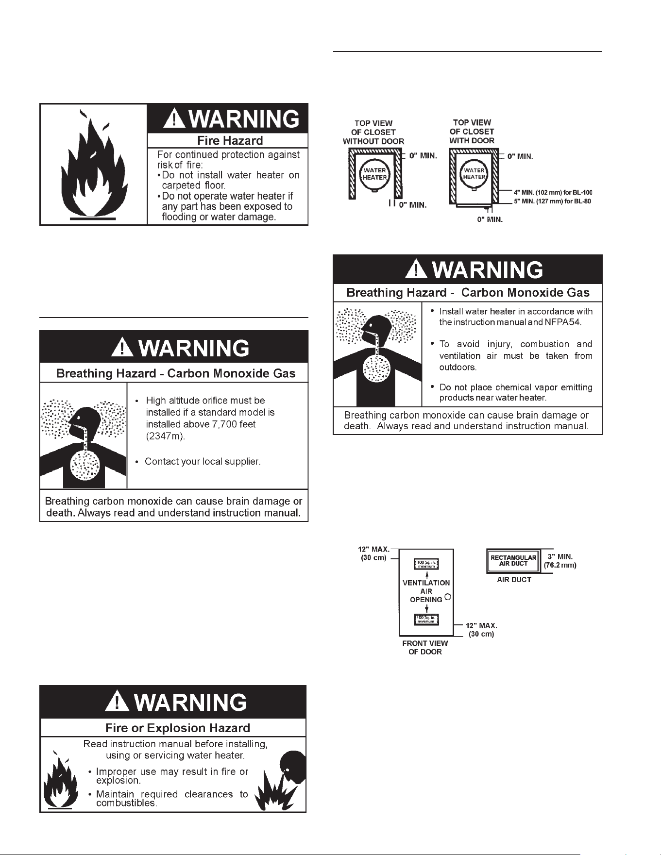
CLEARANCES
Minimum clearances between the water heater and combustible
constructionare0inchatthesidesandrear,4”(102mm)forBCN3100
and5”(127mm)forBCN375atthefront,and6”(153mm)fromthe
ventpipe.Clearancefromthetopofthejacketis12”(305mm).
FIGURE 2.
A gas water heater cannot operate properly without the correct
amount of air for combustion. Do not install in a conned area
suchasacloset,unlessyouprovideairasshownintheFactsto
ConsiderAbout The Location section. Never obstruct the ow of
ventilationair.Ifyouhaveanydoubtsorquestionsatall,callyour
gassupplier.Failuretoprovidetheproperamountofcombustion
aircanresultinareorexplosionandcausedeath,seriousbodily
injury,orpropertydamage.
FIGURE 3.
Ifthiswaterheaterwillbeusedinbeautyshops,barbershops,
cleaning establishments,or self-servicelaundrieswithdry
cleaning equipment, it is imperative that the water heater or
water heaters be installed so that combustionand ventilation
airbetakenfromoutsidetheseareas.
Propellantsofaerosolspraysandvolatilecompounds,(cleaners,
chlorinebasedchemicals,refrigerants,etc.)inadditiontobeing
highlyammableinmanycases,willalsochangetocorrosive
hydrochloricacidwhenexposedtothecombustionproductsof
thewaterheater.Theresultscanbehazardous,andalsocause
productfailure.
9
INSULATION BLANKETS
Do not obstruct water heater air intake
with insulating blanket.
Gas and carbon monoxide detectors
are available.
Install water heater in accordance with
the instruction manual.
Breathing carbon monoxide can cause brain damage or
death. Always read and understand instruction manual.
Breathing Hazard - Carbon Monoxide Gas
Insulation blankets are available to the general public for
external use on gas water heaters but are not necessary
with these products. The purpose of an insulation blanketis
to reduce the standby heat loss encountered with storage
tankheaters.Thewaterheaterscoveredbythismanualmeet
or exceed the Energy Policy Act standards with respect to
insulation and standby heat loss requirements, making an
insulationblanketunnecessary.
Shouldyouchoosetoapplyaninsulationblankettothisheater,
you should follow these instructions. See the Installation
Considerations section of this manual for identification
of components mentioned below. Failure to follow these
instructions can restrict the air flow required for proper
combustion,potentially resultinginfire,asphyxiation,serious
personalinjuryordeath.
• DO NOTapplyinsulationtothetopofthewaterheater,as
thiswillinterferewithsafeoperationofthedrafthood.
• DO NOTcoverthethermostatortheTemperature-
PressureReliefValve.
• DO NOTallowtheinsulationtocomewithin2inches(5
cm)ofthefloortopreventblockageofcombustionairflow
totheburner.
• DO NOTcovertheinstructionmanual.Keepitontheside
ofthewaterheaterornearbyforfuturereference.
• DOobtainnewwarningandinstructionlabelsfromthe
manufacturerforplacementontheblanketdirectlyover
theexistinglabels.
• DOinspecttheinsulationblanketfrequentlytomake
certainitdoesnotsag,therebyobstructingthe
combustionairflow.
HARD WATER
Wherehardwaterconditionsexist,watersofteningorthethreshold
type of water treatment is recommended. This will protect the
dishwashers,coffeeurns,waterheaters,waterpipingandother
equipment. See the Maintenance Section in this manual for
sedimentandlimescaleremovalprocedures.
CIRCULATION PUMPS
Acirculatingpumpisusedwhenasystemrequiresacirculating
loop or there is a storage tank used in conjunction with the
water heater. See Water Piping Diagrams in this manual for
installationlocationofcirculatingpumps.
SeetheCirculationPumpWiringDiagramsbelowforelectrical
hookup information. Install in accordance with the current
edition of the National Electrical Code, NFPA 70 or the
CanadianElectricalCode,CSAC22.1.
Allbronzeorstainlesssteelcirculatingpumpsarerecommended
forusedwithcommercialwaterheaters.
Somecirculatingpumpsaremanufacturedwithsealedbearings
anddonotrequirefurtherlubrication.Somecirculatingpumps
must beperiodically oiled.Refertothepumpmanufacturer’s
instructionsforlubricationrequirements.
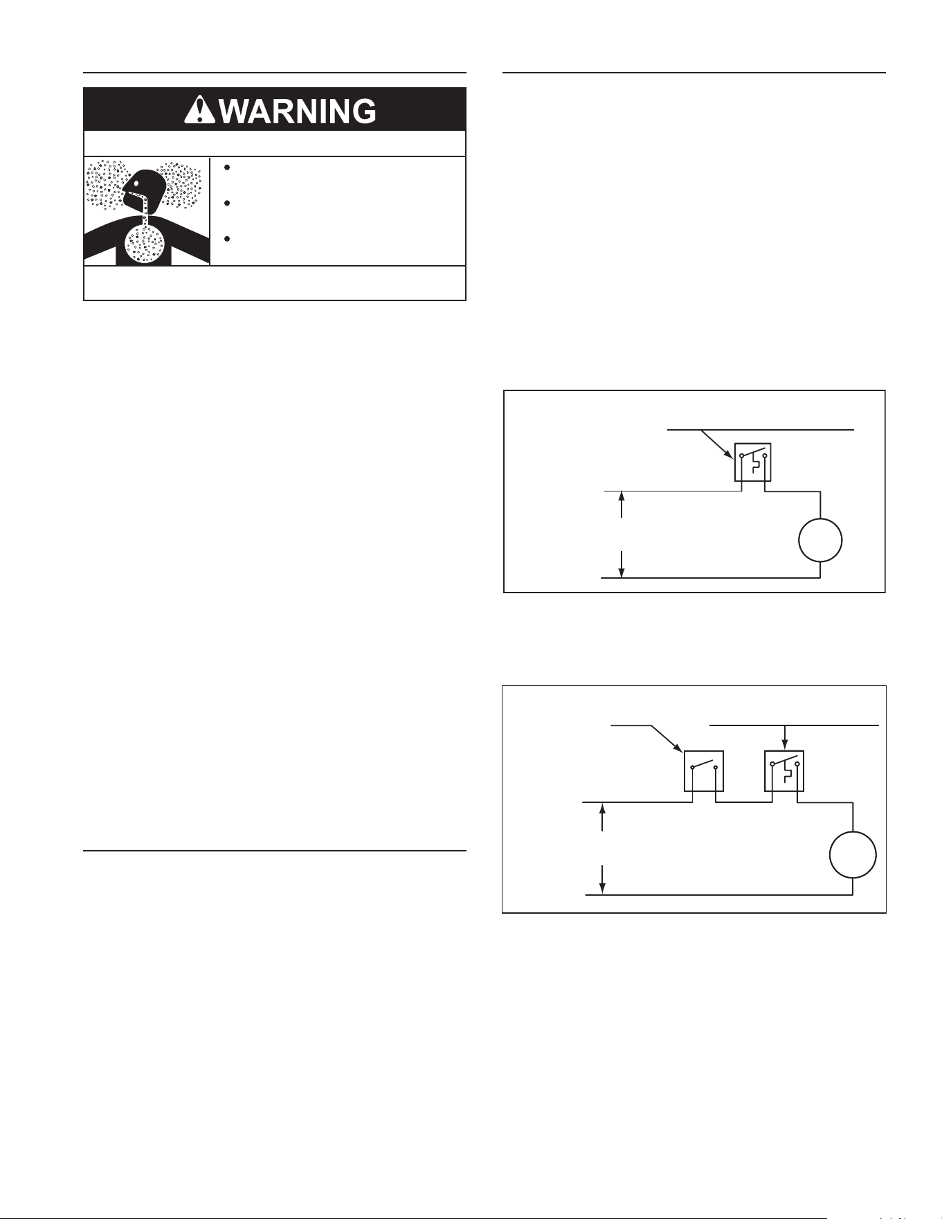
CIRCULATING PUMP WIRING DIAGRAM
STORAGE TANK OR BUILDING RECIRCULATION
FIELD SUPPLIED TEMPERATURE CONTROL
INSTALLED IN THE STORAGE TANK
OR CIRCULATING LOOP RETURN LINE
CIRC
PUMP
MOTOR
L1 HOT
L2 NEUTRAL
120 VAC
POWER
NOTE: USE SEPARATE 120 VAC POWER
SUPPLY FOR PUMP CIRCUIT. DO NOT
SHARE POWER WITH WATER HEATER AS THIS
MAY CAUSE ELECTRICAL LINE NOISE AND
LEAD TO ERRATIC CONTROL SYSTEM
OPERATION.
FIGURE 4.
CIRCULATING PUMP WIRING DIAGRAM
DISHWASHER LOOP WITH TOGGLE SWITCH
FIELD SUPPLIED TEMPERATURE
CONTROL INSTALLED IN THE
CIRCULATING LOOP RETURN LINE
DISHWASHER
TOGGLE
SWITCH
CIRC
PUMP
MOTOR
L1 HOT
L2 NEUTRAL
120 VAC
POWER
NOTE: USE SEPARATE 120 VAC POWER
SUPPLY FOR PUMP CIRCUIT. DO NOT
SHARE POWER WITH WATER HEATER AS
THIS MAY CAUSE ELECTRICAL LINE NOISE
AND LEAD TO ERRATIC CONTROL SYSTEM
OPERATION.
FIGURE 5.
10
GAS SUPPLY SYSTEMS
Low pressure building gas supply systems are dened as those
systemsthatcannotunderanycircumstancesexceed14”W.C.
(1/2PSIGauge).Thesesystemsdonotrequirepressureregulation.
Measurementsshouldbetakentoinsurethatgaspressuresarestable
andfallwithintherequirementsstatedonthewaterheaterratingplate.
readingsshouldbe takenwithall gas burningequipment off(static
pressure)andwithallgasburningequipmentrunningatmaximumrate
(dynamicpressure).Thegassupplypressuremustbestablewithin1.5”
W.C.fromstatictodynamicpressuretoprovidegoodperformance.
Pressuredropsthatexceed1.5”W.C.maycauseroughstarting,noisy
combustionornuisanceoutages.Increasesorspikesinstaticpressure
duringoffcyclesmaycausefailuretoigniteorinseverecasesdamage
toappliancegasvalves.Ifyourlowpressuresystemdoesnotmeet
theserequirements,theinstallerisresponsibleforthecorrections.
HighPressurebuildingsupplysystemsusepressuresthatexceed
14” W.C. (1/2 PSI Gauge). These systems must use eldsupplied
regulatorstolowerthegaspressuretolessthan14”W.C.(1/2PSI
Gauge).Appliancesrequiregasregulatorsthatareproperlysizedforthe
waterheaterinputanddelivertheratingplatespeciedpressures.Gas
supplysystemswherepressureexceeds5PSIoftenrequiremultiple
regulatorstoachievedesiredpressures.Systemsinexcessof5PSI
buildingpressureshouldbedesignedbygasdeliveryprofessionals
forbestperformance.Waterheatersconnectedtogassupplysystems
thatexceed14”W.C.(1/2PSIGauge)atanytimemustbeequipped
withagassupplyregulator.
GAS PRESSURE REQUIREMENTS
BCN3100naturalgasmodelrequiresaminimumgassupplypressure
of5”w.c.(1.25kPa);BCN375naturalgasmodelrequiresaminimum
gas supply pressure of 6” w.c. (1.49 kPa). The minimum supply
pressureismeasuredwhilegasisowing(dynamicpressure).The
supplypressure(dynamic)shouldneverfallbelowthespecied
minimumsupplypressure.Thesupplypressureshouldbemeasured
withallgasredappliancesconnectedtothecommonmainringatfull
capacity.Ifthesupplypressuredropsmorethan1.5”W.C.(0.37kPa)
asgasbeginstoowtothewaterheaterthenthesupplygassystem
includingthegaslineand/orthegasregulatormayberestricted or
undersized.SeeSupplyGasregulatorsectionandGasPipingsection
ofthismanual.Thegasvalveonallmodelshasamaximumgassupply
pressurelimitof14”W.C.(3.48kPa)Themaximumsupplypressure
ismeasuredwhilegasisnotowing(staticpressure).
SUPPLY GAS REGULATOR
Themaximumallowablegassupplypressureforthiswaterheater
is14.0inchesW.C.(3.48kPa).Installapositivelock-upgaspressure
regulatorinthegassupplylineifinletgaspressurecanexceed14.0
inchesW.C.(3.48kPa) at anytime. regulatorsmustbe sized/used
accordingtomanufacturer’sspecications.
Ifapositivelock-upregulatorisrequiredfollowtheseinstructions:
1. Positivelock-upgaspressureregulatorsmustberatedatorabove
theinputBtu/hrratingofthewaterheatertheysupply.
2. Positivelock-upgaspressureregulator(s)shouldbeinstalledno
closerthan3feet(1meter)andnofartherthan8feet(2.4meters)
ofequivalentlengthfromthewaterheater’sinletgasconnection.
3. Afterinstallingthepositivelock-upgaspressureregulator(s)aninitial
nominalsupplypressuresettingof7.0”W.C.whilethewaterheater
isoperatingisrecommendedandwillgenerallyprovidegood
waterheateroperation.Someadditionaladjustmentmayberequired
latertomaintainasteadygassupplypressure.
4. When installing multiple water heaters in the same gas supply
system it is recommended that individual positive lock-up gas
pressureregulatorsbeinstalledateachunit.
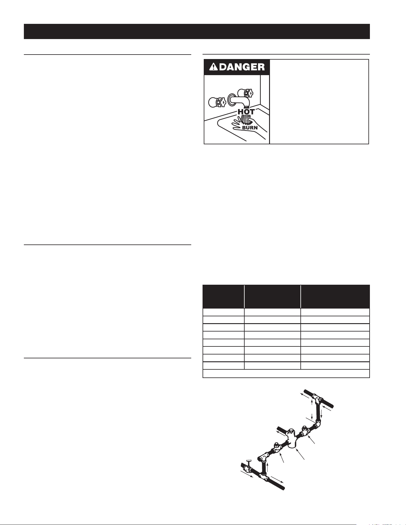
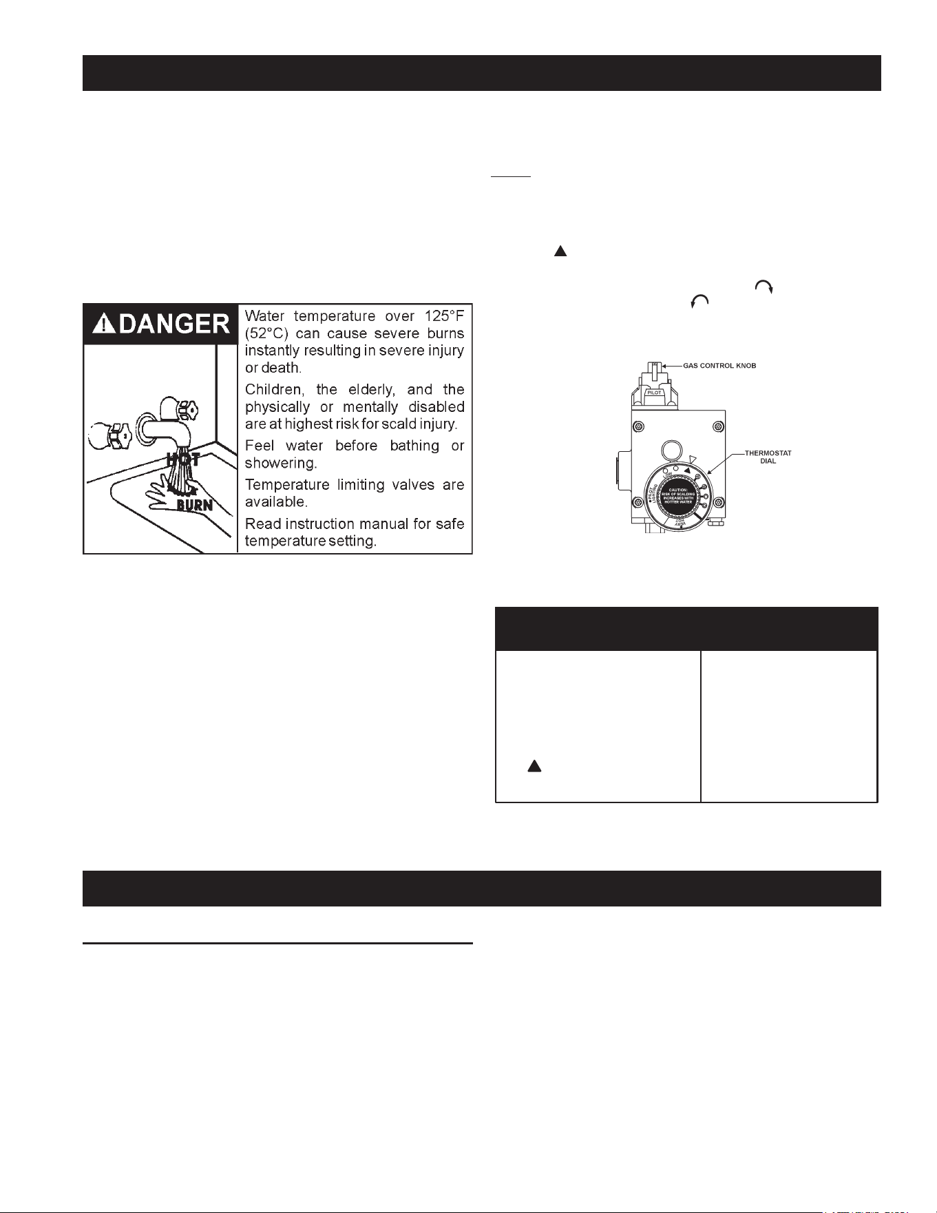
MIXING VALVES
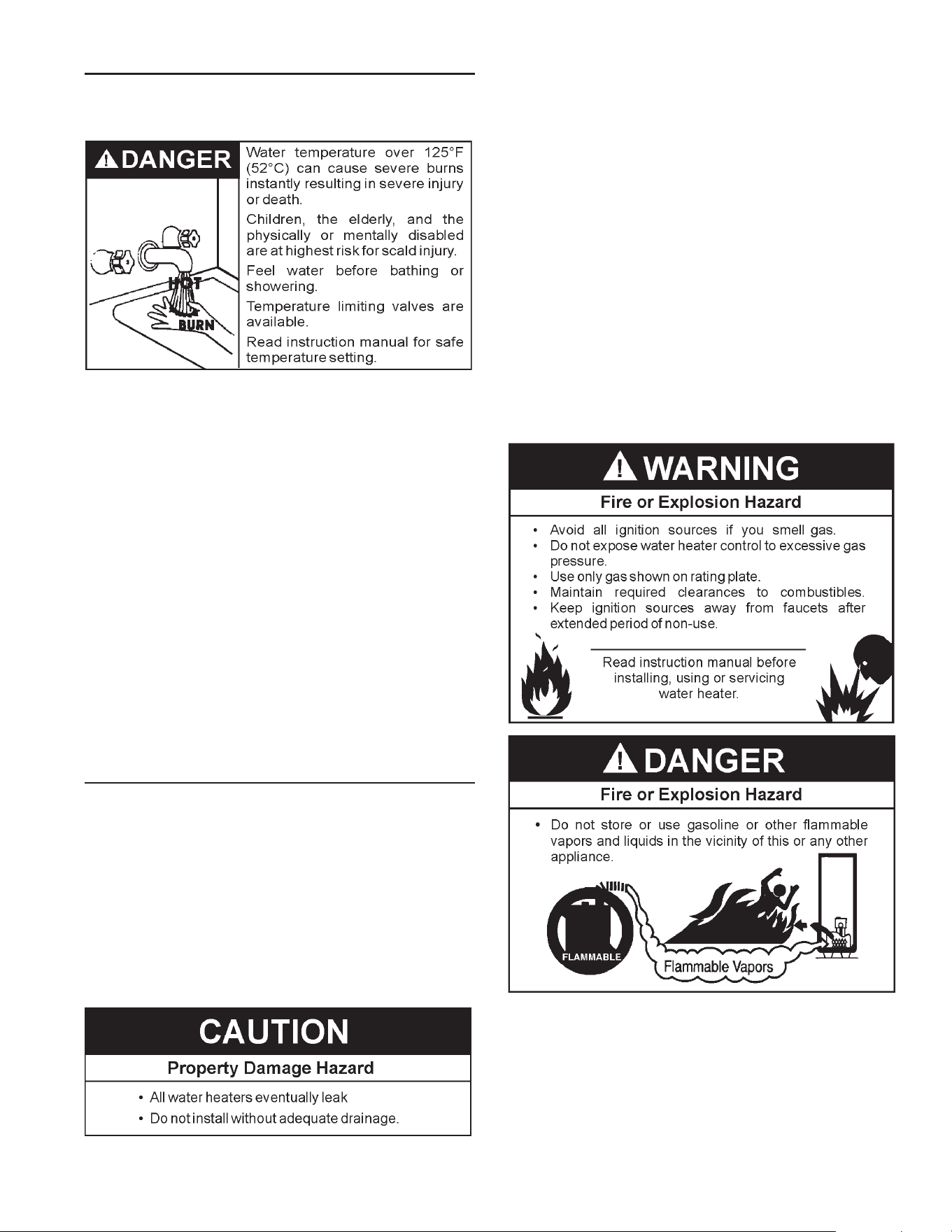
Water temperature over 125°F (52°C)
can cause severe burns instantly
resulting in severe injury or death.
Children, the elderly and the physically
or mentally disabled are at highest risk
for scald injury.
Feel water before bathing or showering.
Temperature limiting devices such as
mixing valves must be installed when
required by codes and to ensure safe
temperatures at fixtures.
Waterheatedtoatemperaturewhichwillsatisfyclotheswashing,dish
washing,andothersanitizingneedscanscaldandcausepermanent
injuryuponcontact.Shortrepeatedheatingcyclescausedbysmall
hotwaterusescancausetemperaturesatthepointofusetoexceed
thewaterheater’stemperaturesettingbyupto20°F(11°C).
Somepeoplearemorelikelytobepermanentlyinjuredbyhotwater
than others. These include the elderly, children, the inrm and the
physically/mentally disabled. Table 2 shows the approximate time-
to-burnrelationshipfornormaladultskin.Ifanyoneusinghotwater
provided by the water heater being installed ts into one of these
groupsorifthereisalocalcodeorstatelawrequiringacertainwater
temperatureatthepointofuse,thenspecialprecautionsmustbetaken.
In addition to using the lowest possible temperature setting that
satisesdemandoftheapplicationaMixingValveshouldbeinstalled
atthewaterheaterorathotwatertapstofurtherreducesystemwater
temperature.SeeFigure6.
Mixing valves are available at plumbing supply stores. Consult
a Qualied Installer or Service Technician. Follow mixing valve
manufacturer’sinstructionsforinstallationofthevalves.
TABLE 2.
Water
Temperature°F
Timefor
1stDegreeBurn
(LessSevereBurns)
TimeforPermanentBurns
2nd&3rdDegree
(MostSevereBurns)
110
(normalshowertemp.)
116 (painthreshold)
116 35minutes 45minutes
122 1minute 5minutes
131 5seconds 25seconds
140 2seconds 5seconds
149 1second 2seconds
154 instantaneous 1second
(U.S.GovernmentMemorandum,C.P.S.C.,PeterL.Armstrong,Sept.15,1978)
HOT WATER
OUTLET
TO TANK
INLET
CHECK
VALVE
MIXING
VALVE
COLD
WATER
INLET
TEMPERED WATER
OUTLET
12” TO 15”
(30-38 cm)
CHECK
VALVE
FIGURE 6.
INSTALLATION REQUIREMENTS
11
WATER PIPING
WATER (POTABLE) HEATING AND SPACE HEATING
Thiswaterheatershallnotbeconnectedtoanyheatingsystems
orcomponent(s)usedwithanon-potablewaterheatingappliance.
Allpipingcomponentsconnectedtothisunitforspaceheating
applicationsshallbesuitableforusewithpotablewater.
Toxicchemicals,suchasthoseusedforboilertreatmentshallnot
beintroducedintothissystem.
Whenthesystemrequireswaterforspaceheatingattemperatures
higherthanrequiredfordomesticwaterpurposes,amixingvalve
mustbeinstalled.PleaserefertoFigure6forsuggestedpiping
arrangement.
Thesewaterheaterscannotbeusedinspaceheatingapplications
only.
CLOSED WATER SYSTEMS
Water supply systems may, because of code requirements or
such conditions as high line pressure, among others, have
installed devices such as pressure reducing valves, check
valves,andbackflowpreventers.Devicessuchasthesecause
thewatersystemtobeaclosedsystem.
THERMAL EXPANSION
Aswaterisheated,itexpands(thermalexpansion).Inaclosed
systemthevolumeofwaterwillgrowwhenitisheated.Asthe
volumeofwatergrowstherewillbeacorrespondingincreasein
water pressure due to thermal expansion. Thermal expansion
cancauseprematuretankfailure(leakage).Thistypeoffailure
is not covered under the limited warranty. Thermal expansion
canalsocauseintermittentTemperature-PressureReliefValve
operation: water discharged from the valve due to excessive
pressurebuildup.Thisconditionisnotcoveredunderthelimited
warranty.TheTemperature-PressureReliefValveisnotintended
fortheconstantreliefofthermalexpansion.
A properly sized thermal expansion tank must be installed on
all closed systems to control the harmful effects of thermal
expansion.Contactalocalplumbingservicetechniciantohave
athermalexpansiontankinstalled.
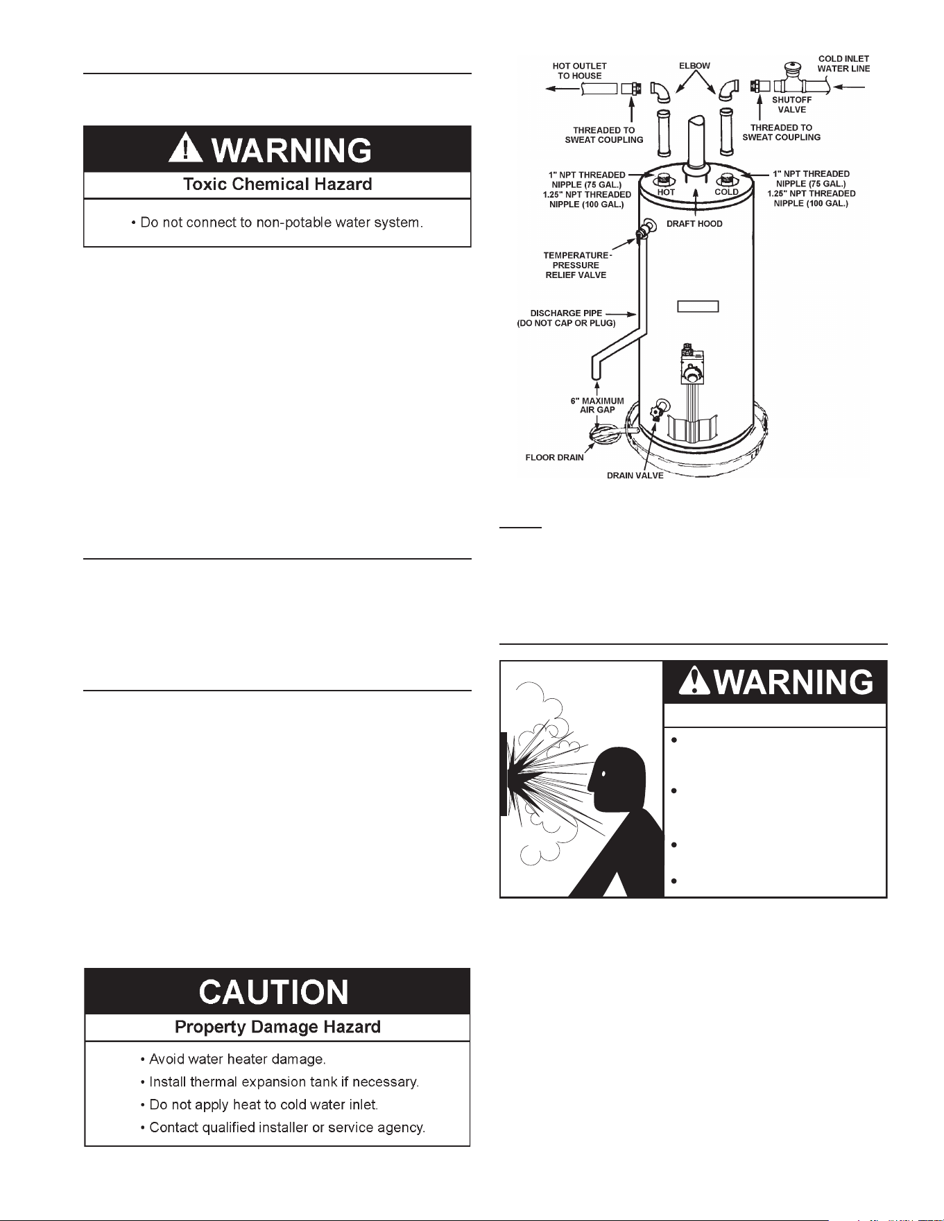
FIGURE 7.
NOTE: To protect against untimely corrosion of hot and cold
waterttings,itisstronglyrecommendedthatdi-electricunions
orcouplingsbeinstalledonthiswaterheaterwhenconnectedto
copperpipe.
Figure7showsthetypicalattachmentofthewaterpipingtothe
waterheater.
TEMPERATURE-PRESSURE RELIEF VALVE
Explosion Hazard
Temperature-Pressure Relief Valve
must comply with ANSI Z21.22-
CSA 4.4 and ASME code.
Properly sized temperature-
pressure relief valve must be
installed in opening provided.
Can result in overheating and
excessive tank pressure.
Can cause serious injury or death.
Thiswaterheaterisprovidedwithaproperlyrated/sizedand
certifiedcombinationTemperature-PressureReliefValve(T&P
valve)bythemanufacturer.Thevalveiscertifiedbyanationally
recognizedtestinglaboratorythatmaintainsperiodicinspection
ofproductionoflistedequipmentofmaterialsasmeetingthe
requirementsforReliefValvesforHotWaterSupplySystems,
ANSIZ21.22•CSA4.4,andthecoderequirementsofASME.
Ifreplaced,thenewT&Pvalvemustmeettherequirements
oflocalcodes,butnotlessthanacombinationTemperature-
PressureReliefValverated/sizedandcertifiedasindicatedin
theaboveparagraph.Thenewvalvemustbemarkedwitha
maximumsetpressurenottoexceedthemarkedhydrostatic
workingpressureofthewaterheater(150psi=1,035kPa)
andadischargecapacitynotlessthanthewaterheaterBtu/
hr or kW input rate as shown on the water heater’s model
ratinglabel.
12
NOTE: Inadditionto the factoryinstalled Temperature-Pressure
ReliefValveon thewaterheater,eachremote storagetank that
maybeinstalledandpipedtoawaterheatingappliancemustalso
have its own properly sized, rated and approved Temperature-
PressureReliefValveinstalled.Callthetollfreetechnicalsupport
phonenumberlistedonthebackcoverofthismanualfortechnical
assistanceinsizingaTemperature-PressureReliefValveforremote
storagetanks.
Forsafe operationof thewater heater, theTemperature-Pressure
ReliefValvemustnotberemovedfromitsdesignatedopeningnor
plugged.TheTemperature-PressureReliefValvemustbeinstalled
directlyintothettingofthewaterheaterdesignedforthereliefvalve.
Installdischargepipingsothatanydischargewillexitthepipewithin
6inches(15.2cm)aboveanadequateoordrain,orexternaltothe
building.Incoldclimatesitisrecommendedthatitbeterminatedat
anadequatedraininsidethebuilding.Becertainthatnocontactis
madewithanyliveelectricalpart.Thedischargeopeningmustnot
beblockedorreducedinsizeunderanycircumstances.Excessive
length,over30feet(9.14m),oruseofmorethanfourelbowscan
causerestrictionandreducethedischargecapacityofthevalve.
No valve or other obstruction is to be placed between the
Temperature-PressureReliefValveandthetank.Donotconnect
dischargepipingdirectlytothedrainunlessa6”(15.2cm)airgapis
provided.Topreventbodilyinjury,hazardtolife,orpropertydamage,
thereliefvalve must beallowed to discharge waterin adequate
quantitiesshouldcircumstancesdemand.Ifthedischargepipeis
notconnectedtoadrainorothersuitablemeans,thewaterow
maycausepropertydamage.
Water Damage Hazard
•
Temperature-Pressure Relief Valve discharge
pipe must terminate at adequate drain.
CAUTION
T&P Valve Discharge Pipe Requirements:
• Shallnotbesmallerinsizethantheoutletpipesizeofthevalve,
orhaveanyreducingcouplingsorotherrestrictions.
• Shallnotbepluggedorblocked.
• Shallnotbeexposedtofreezingtemperatures.
• Shallbeofmateriallistedforhotwaterdistribution.
• Shallbeinstalledsoastoallowcompletedrainageofboththe
Temperature-PressureReliefValveandthedischargepipe.
• Mustterminateamaximumofsixinchesaboveaoordrain
orexternaltobuilding.Incoldclimates,itisrecommended
thatdischargepipebeterminatedatanadequatedraininside
building.
• Shallnothaveanyvalveorotherobstructionbetweenthe
reliefvalveandthedrain.
Burn hazard.
Hot water discharge.
Keep clear of Temperature-
Pressure Relief Valve
discharge outlet.
TheTemperature-PressureReliefValvemustbemanuallyoperated
atleasttwiceayear.Cautionshouldbetakentoensurethat(1)no
oneisinfrontoforaroundtheoutletoftheTemperature-Pressure
ReliefValvedischargeline,and(2)thewatermanuallydischarged
will not cause any bodily injury or property damage because
thewater maybeextremelyhot.If aftermanually operatingthe
valve,itfailstocompletelyresetandcontinuestoreleasewater,
immediatelyclosethecoldwaterinlettothewaterheater,followthe
draininginstructionsinthismanual,andreplacetheTemperature-
PressureReliefValvewithaproperlyrated/sizednewone.
NOTE:ThepurposeofaTemperature-PressureReliefValveisto
preventexcessivetemperaturesandpressuresinthestoragetank.
The T&Pvalve is not intended for the constant relief of thermal
expansion.Aproperlysizedthermalexpansiontankmustbeinstalled
on all closed systems to control thermal expansion, see Closed
WaterSystemsandThermalExpansiononpage11.
If you do not understand these instructions or have any questions
regardingtheTemperature-PressureReliefValvecallthetollfreenumber
listedonthebackcoverofthismanualfortechnicalassistance.
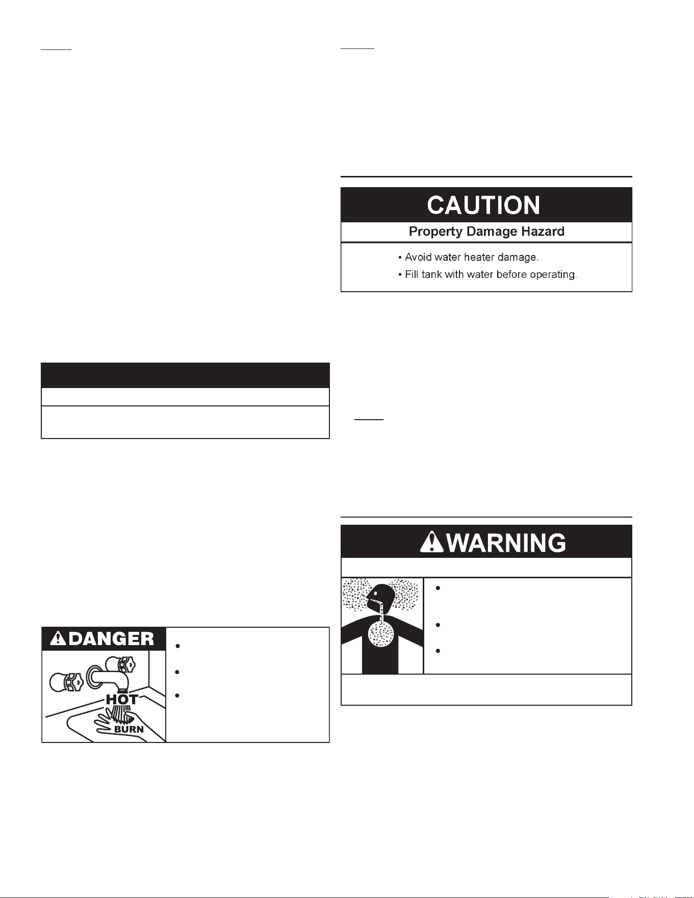
FILLING THE WATER HEATER
Neverusethis waterheaterunless itiscompletely fullofwater.To
preventdamagetothetank,thetankmustbelledwithwater.Water
mustowfromthehot waterfaucetbeforeturning“ON” gastothe
waterheater.
Tollthewaterheaterwithwater:
1.Close the water heater drain valvebyturningthe handle to the
right(clockwise).Thedrainvalveisonthelowerfrontofthewater
heater.
2. Open the cold water supply valve to the water heater.
NOTE:Thecoldwatersupplyvalvemustbeleftopenwhenthe
waterheaterisinuse.
3.Toinsurecompletellingofthetank,allowairtoexitbyopeningthe
nearesthotwaterfaucet.Allowwatertorununtilaconstantowis
obtained.Thiswillletairoutofthewaterheaterandthepiping.
4. Checkallwaterpipingandconnectionsfor leaks. Repair as
needed.
AIR REQUIREMENTS
Breathing Hazard - Carbon Monoxide Gas
Install water heater in accordance with
the Instruction Manual and NFPA 54 or
CAN/CSA-B149.1.
To avoid injury, combustion and ventilation
air must be taken from outdoors.
Do not place chemical vapor emitting
products near water heater.
Breathing carbon monoxide can cause brain damage or
death. Always read and understand instruction manual.
For safe operation an adequate supply of fresh uncontaminated air for
combustionandventilationmustbeprovided.
An insufcient supply of air can cause recirculation of combustion
products resulting in contamination that may be hazardous to life.
Suchaconditionoftenwillresultinayellow,luminousburnerame,
causingsootingofthecombustionchamber,burnersanduetubes
andcreatesariskofasphyxiation.
Donotinstallthewaterheaterinaconnedspaceunlessanadequate
supplyofairforcombustionandventilationisbroughtintothatspace
usingthemethodsdescribedintheConnedSpacesectionthatfollows.
Neverobstructtheowofventilationair.Ifyouhaveanydoubtsor
questionsat all,call yourgas supplier. Failureto providetheproper
13
amountofcombustionaircanresultinareorexplosionandcauseproperty
damage,seriousbodilyinjuryordeath.
UNCONFINED SPACE
AnUnconfinedSpaceisonewhosevolumeisnotlessthan50
cubic feet per 1,000 Btu/hr (4.8 cubic meters per kW) of the
totalinputratingofallappliancesinstalledinthespace.Rooms
communicatingdirectlywith thespace,inwhichtheappliances
are installed, through openings not furnished with doors, are
consideredapartoftheunconfinedspace.
Makeupairrequirementsfortheoperationofexhaustfans,kitchen
ventilationsystems, clothes dryersand fireplacesshallalso be
considered in determining the adequacy of a space to provide
combustion,ventilationanddilutionair.
UNUSUALLY TIGHT CONSTRUCTION
Inunconfinedspacesinbuildings,infiltrationmaybeadequateto
provideairforcombustion,ventilationanddilutionoffluegases.
However,inbuildingsofunusuallytightconstruction(forexample,
weatherstripping,heavilyinsulated,caulked,vaporbarrier,etc.)
additionalairmustbeprovidedusingthemethodsdescribedin
theConfinedSpacesectionthatfollows.
CONFINED SPACE
AConnedSpaceisonewhosevolumeislessthan50cubicfeetper
1,000Btu/hr(4.8cubicmetersperkW)ofthetotalinputratingofall
appliancesinstalledinthespace.
Openingsmustbeinstalledtoprovidefreshairforcombustion,ventilation
and dilution in conned spaces. The required size for the openings is
dependentonthemethodusedtoprovidefreshairtotheconnedspace
andthetotalBtu/hrinputratingofallappliancesinstalledinthespace.
DIRECT VENT APPLIANCES
Appliances installed in a Direct Vent conguration that derive all
air for combustion from the outdoor atmosphere through sealed
intakeairpipingarenotfactoredinthetotalapplianceinputBtu/hr
calculationsusedtodeterminethesizeofopeningsprovidingfresh
airintoconnedspaces.
EXHAUST FANS
Whereexhaustfansareinstalled,additionalairshallbeprovided
toreplacetheexhaustedair.Whenanexhaustfanisinstalledin
thesamespacewithawaterheater,sufficientopeningstoprovide
freshairmustbeprovidedthataccommodatetherequirements
forallappliancesintheroomandtheexhaustfan.Undersized
openingswillcauseairtobedrawnintotheroomthroughthewater
heater’sventsystemcausingpoorcombustion.Sooting,serious
damagetothewaterheaterandtheriskoffireorexplosionmay
result.Itcanalsocreateariskofasphyxiation.
LOUVERS AND GRILLES
Thefreeareasofthefreshairopeningsintheinstructionsthatfollowdonot
takeintoaccountthepresenceoflouvers,grillesorscreensintheopenings.
Therequiredsizeofopeningsforcombustion,ventilationanddilution
airshallbebasedonthe“netfreearea”ofeachopening.Wherethe
freeareathroughadesignoflouverorgrilleorscreenisknown,itshall
beusedincalculatingthesizeofopeningrequiredtoprovidethefree
areaspecied.Wherethelouverandgrilledesignandfreeareaarenot
known,itshallbeassumedthatwoodlouverswillhave25%freearea
andmetallouversandgrilleswillhave75%freearea.Nonmotorized
louversandgrillesshallbexedintheopenposition.
FRESH AIR OPENINGS FOR CONFINED SPACES
The following instructions shall be used to calculate the size,
number and placement of openings providing fresh air for
combustion, ventilation and dilution in confined spaces. The
illustrationsshowninthissectionofthemanualareareference
for the openings that provide freshairintoconfined spaces
only.Donot refertotheseillustrationsforthepurposeofvent
installation. See Venting Installation on page 14 for complete
ventinginstallationinstructions.
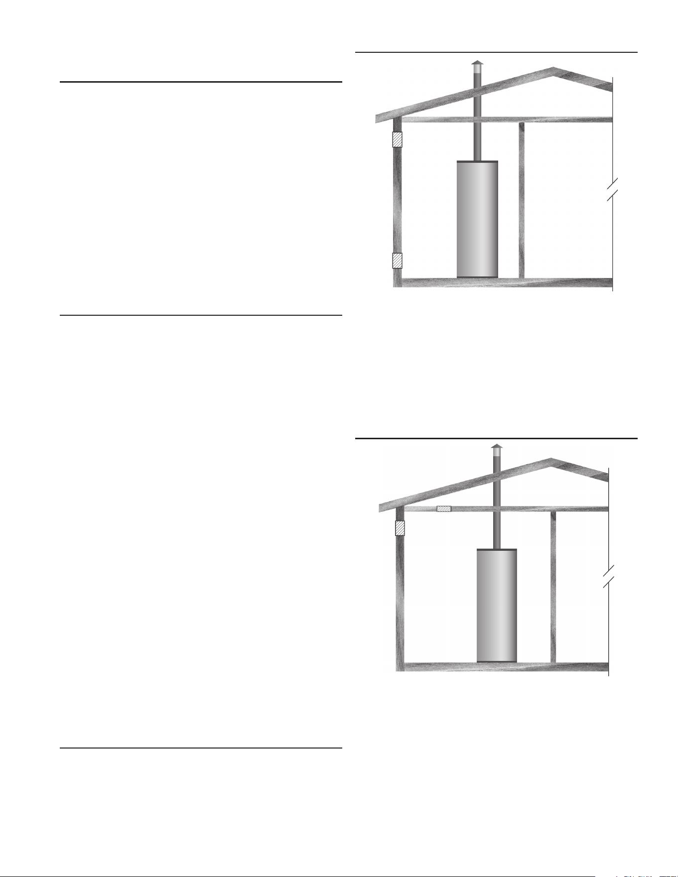
OUTDOOR AIR THROUGH TWO OPENINGS
FIGURE 8.
The confined space shall be provided with two permanent
openings,onecommencingwithin12inches(300mm)ofthetop
andonecommencingwithin12inches(300mm)ofthebottomof
the enclosure. The openings shall communicate directly with the
outdoors.SeeFigure8.
Eachopeningshallhaveaminimumfreeareaof1squareinchper
4,000Btu/hr(550mm2perkW)oftheaggregateinputratingofall
appliancesinstalledintheenclosure.Eachopeningshallnotbeless
than100squareinches(645cm2).
OUTDOOR AIR THROUGH ONE OPENING
FIGURE 9.
Alternatively a single permanent opening, commencing within 12
inches(300mm)ofthetopoftheenclosure,shallbeprovided.See
Figure9.Thewaterheatershallhaveclearancesofatleast1inch
(25mm)fromthesidesandbackand6inches(150mm)fromthe
frontoftheappliance.Theopeningshalldirectlycommunicatewith
theoutdoorsorshallcommunicatethroughaverticalorhorizontalduct
totheoutdoorsorspacesthatfreelycommunicatewiththeoutdoors
andshallhaveaminimumfreeareaofthefollowing:
1. 1 squareinchper3000 Btu/hr (733 mm
2
perkW)ofthe total
inputratingofallapplianceslocatedintheenclosure,and
2. Notlessthanthesumoftheareasofallventconnectorsin
thespace.
14
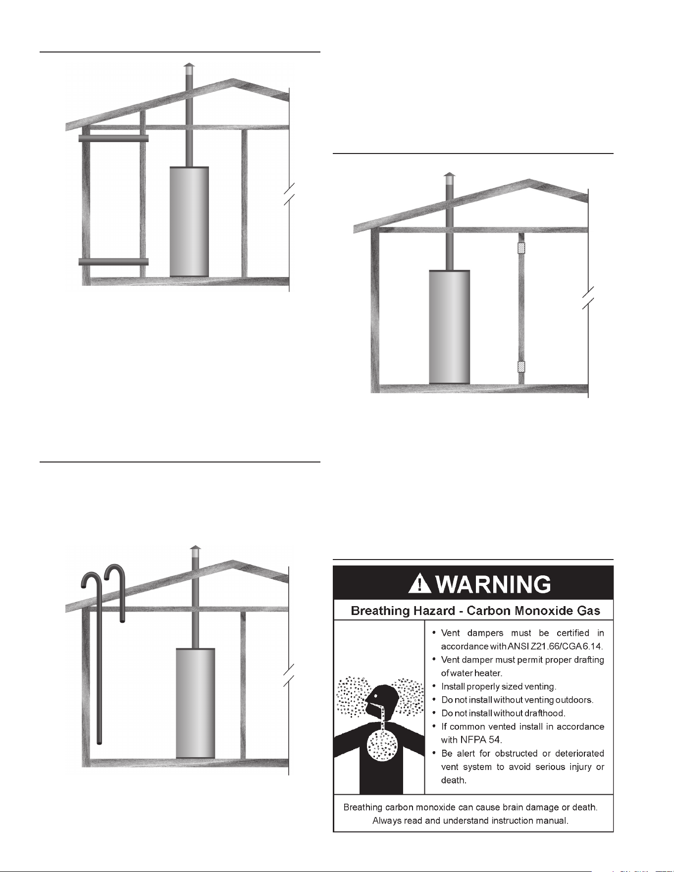
OUTDOOR AIR THROUGH TWO HORIZONTAL DUCTS
FIGURE 10.
Theconnedspaceshallbeprovidedwithtwopermanenthorizontal
ducts,one commencingwithin12inches(300mm)of thetop and
one commencing within 12 inches (300 mm) of the bottom of the
enclosure.Thehorizontalductsshallcommunicatedirectlywiththe
outdoors.SeeFigure10.
Eachductopeningshallhaveaminimumfreeareaof1squareinch
per2,000Btu/hr(1100mm2perkW)oftheaggregateinputratingof
allappliancesinstalledintheenclosure.
Whenductsareused,theyshallbeofthesamecrosssectionalarea
asthefreeareaoftheopeningstowhichtheyconnect.Theminimum
dimensionofrectangularairductsshallbenotlessthan3inches.
OUTDOOR AIR THROUGH TWO VERTICAL DUCTS
The illustrations shown in this section of the manual are a
reference for the openings that provide fresh air into conned
spacesonly.
DO NOT refer to these illustrations for the purpose of vent
installation. See Venting Installation on page 14 for complete
ventinginstallationinstructions.
FIGURE 11.
Theconnedspace shall be provided withtwopermanent vertical
ducts,one commencingwithin12inches(300mm)of thetop and
one commencing within 12 inches (300 mm) of the bottom of the
enclosure. The vertical ducts shall communicate directly with the
outdoors.SeeFigure11.
Eachductopeningshallhaveaminimumfreeareaof1squareinch
per4,000Btu/hr(550mm2perkW)oftheaggregateinputratingof
allappliancesinstalledintheenclosure.
Whenductsareused,theyshallbeofthesamecrosssectionalarea
asthefreeareaoftheopeningstowhichtheyconnect.Theminimum
dimensionofrectangularairductsshallbenotlessthan3inches.
AIR FROM OTHER INDOOR SPACES
FIGURE 12.
Theconnedspaceshallbeprovidedwithtwopermanentopenings,
one commencing within 12 inches (300 mm) of the top and one
commencingwithin12inches(300mm)ofthebottomoftheenclosure.
SeeFigure12.
Eachopeningshallcommunicatedirectlywithanadditionalroom(s)
ofsufcientvolumesothatthecombinedvolumeofallspacesmeets
thecriteriaforanUnconnedSpace.
Eachopeningshallhaveaminimumfreeareaof1squareinchper
1,000Btu/hr(2200mm2perkW)oftheaggregateinputratingofall
appliancesinstalledintheenclosure.Eachopeningshallnotbeless
than100squareinches(645cm2).
VENTING
15
Water heaters covered in these instructions are Category I,
NaturalDraft appliances.Ifthewaterheater is beinginstalled
asareplacementforanexistingheaterinpre-existingventing,a
thoroughinspectionofexistingventingsystemmustbeperformed
priortoanyinstallationwork.
VENT DAMPERS - Any vent damper, whether it is operated
thermallyorotherwisemustberemovedifitsuseinhibitsproper
draftingofthewaterheater.
ThermallyOperated VentDampers:this gas-red waterheater
hasathermalefciencyatorabove80%whichmayproducea
relativelylowuegastemperature.Suchtemperaturesmaynotbe
highenoughtoproperlyopenthermallyoperatedventdampers.
This would cause spillage of the ue gases and may cause
carbonmonoxidepoisoning.Ventdampersmustbearevidenceof
certicationascomplyingwiththecurrenteditionoftheAmerican
NationalStandardANSIZ21.66CGA6.14(coveringelectrically
andmechanicallyactuatedventdampers).Beforeinstallationof
anyventdamper,consultthelocalgasutilityforfurtherinformation.
Toinsureproperventingofthisgas-firedwaterheater,thecor rect
ventpipediametermustbeutilized.Anyadditionsordeletions
ofothergasappliancesonacommonventwiththiswaterheater
mayadverselyaffecttheoperationofthewaterheater.Consult
yourgassupplierifanysuchchangesareplanned.
Forproperventingincertaininstallations,alargerdiametervent
pipemaybenecessary.Consultyourgassuppliertoaidyouin
determiningtheproperventingforyourwaterheaterfromthevent
tablesinthecurrenteditionoftheNationalFuelGasCodeANSI
Z223.1/NFPA 54 or the Natural Gas and Propane Installation
Code CAN\CSA B 149.1.
Periodicallychecktheventingsystemforsignsofobstructionor
deteriorationandreplaceifneeded.
Thecombustionandventilationairflowmustnotbeobstructed.
The water heater withdrafthood installedmust be connected
toachimneyorlistedventpipesystem,whichterminatestothe
outdoors.Neveroperatethewaterheaterunlessitisventedtothe
outdoorsandhasadequateairsupplytoavoidrisksofimproper
operation,explosionorasphyxiation.
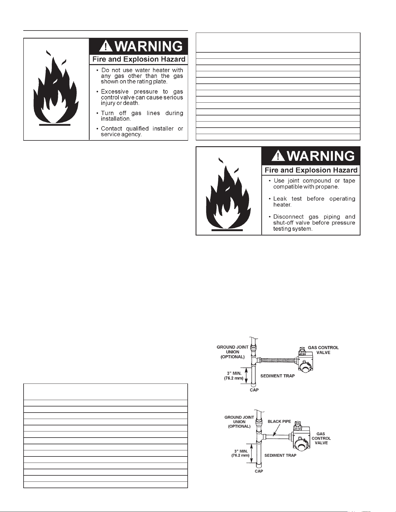
Alignthelegsofthedrafthoodwiththeholesprovided.Insert
the legsand securethedrafthoodtothewater heater’stop
withthefourscrewsprovidedasshowninFigure13.Donot
alterthedrafthoodinanyway.Ifyouarereplacinganexisting
waterheater,besuretousethenewdrafthoodsuppliedwith
thewaterheater.
Obstructed or deteriorated vent systems may present serious
healthriskorasphyxiation.
DRAFT HOOD
SHEET METAL SCREWS (FOUR PROVIDED)
LEGS
HOLE
INSTALL THE DRAFT HOOD WITH
THE FOUR SCREWS PROVIDED.
JACKET TOP
HOLE
LEGS
FIGURE 13.
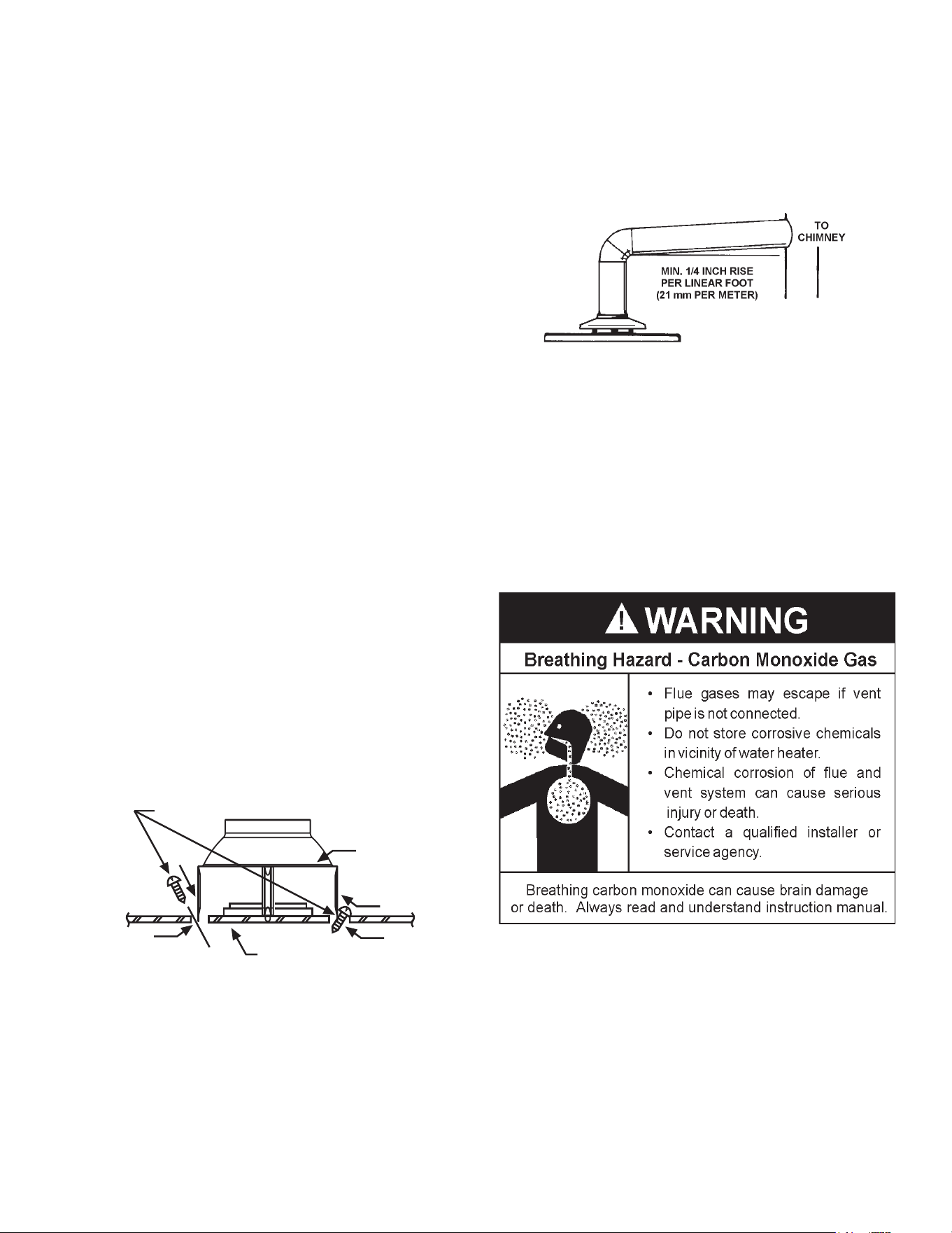
The vent pipe from the water heater must be no less than the
diameter of the draft hood outlet on the water heater and must
slopeupwardatleast1/4inchperlinearfoot(21mmpermeter).
SeeFigure14.
Allventgases must becompletelyvented to theoutdoorsof the
structure(dwelling). Install onlythe drafthood providedwith the
newwaterheaterandnootherdrafthood.
Ventpipesmustbesecuredateachjointwithsheetmetalscrews.
FIGURE 14.
Theremustbeaminimumof6”(153mm)clearancebetweensingle
wall vent pipe and any combustible material. Fill and seal any
clearancebetweensinglewallventpipeandcombustiblematerial
withmortarmix,cement,orothernoncombustiblesubstance.For
other than single wall, followventpipemanufacturer’s clearance
specications.Toinsureatighttoftheventpipeinabrickchimney,
sealaroundtheventpipewithmortarmixcement.
Failure to have required clearances between vent piping and
combustiblematerialwillresultinarehazard.
Be sure vent pipe is properly connected to prevent escape of
dangerousuegaseswhichcouldcausedeadlyasphyxiation.
Chemicalvaporcorrosionoftheflueandventsystemmayoccur
ifairforcombustioncontainscertainchemicalvapors.Spraycan
propellants,cleaningsolvents,refrigeratorandairconditioner
refrigerants,swimming pool chemicals, calcium and sodium
chloride,waxes, bleach and process chemicals aretypical
compoundswhicharepotentiallycorrosive.
16
GAS PIPING
Contact your local gas service company to ensure that adequate
gasserviceisavailableandtoreviewapplicableinstallationcodes
foryourarea.
SizethemaingaslineinaccordancewithTable3.Theguresshown
areforstraightlengthsofpipeat0.5in.W.C.pressuredrop,whichis
considerednormalforlowpressuresystems.Note:Fittingssuchas
elbows,teesandlineregulatorswilladdtothepipepressuredrop.
AlsorefertothecurrenteditionsoftheNationalFuelGasCode(NFPA
54)orNaturalGasandPropaneInstallationCode(CAN/CSAB149.1).
Makesuregassuppliedissametypelistedonmodelratingplate.The
inletgaspressuremustnotexceed14inchwatercolumn(2.6kPa)
fornaturalandpropane(L.P.)gas.Theminimuminletgaspressure
shownonratingplateisthatwhichwillpermitringatratedinput.
Ifthegascontrolvalveissubjectedtopressuresexceeding1/2pound
persquareinch(3.5kPa),thedamagetothegascontrolvalvecould
resultinareorexplosionfromleakinggas.
Ifthemaingaslineshut-offservingallgasappliancesisused,also
turn“off”thegasateachappliance.Leaveallgasappliancesshut
“off”untilthewaterheaterinstallationiscomplete.
Agaslineofsufcientsizemustberuntothewaterheater.Consult
thecurrenteditionofNationalFuelGasCodeANSIZ223.1/NFPA54
ortheNaturalGasandPropaneInstallationCodeCAN/CSAB149.1
andyourgassupplierconcerningpipesize.
Theremustbe:
• Areadily accessiblemanual shutoffvalve inthe gassupply line
servingthewaterheater,and
• Asedimenttrapaheadofthegascontrolvalvetohelppreventdirt
andforeignmaterialsfromenteringthegascontrolvalve.
• Aexiblegasconnectororagroundjointunionbetweentheshut
offvalveandcontrolvalvetopermitservicingoftheunit.
Besuretocheckallthegaspipingforleaksbeforelightingthewater
heater.Useasoapywatersolution,notamatchoropename.Rinse
offsoapysolutionandwipedry.
The minimum inlet gas pressure shown on the rating plate is that
whichwillpermitringattheratedinput.
TABLE 3. GAS SUPPLY LINE SIZES (IN INCHES)*
MAXIMUM CAPACITY OF PIPE IN CUBIC FEET PER HOUR
LENGTH
IN
FEET
NOMINAL IRON PIPE SIZES (
INCHES
)
INPUT IN THOUSANDS (BTU/HR)
1/2" 3/4" 1" 1 1/4" 1 1/2" 2" 2 1/2" 3" 4"
10 175 360 680 1400 2100 3960 6300 11000 23000
20 120 250 465 950 1460 2750 4360 7700 15800
30 97 200 375 770 1180 2200 3520 6250 12800
40 82 170 320 660 990 1900 3000 5300 10900
50 73 151 285 580 900 1680 2650 4750 9700
60 66 138 260 530 810 1520 2400 4300 8800
70 61 125 240 490 750 1400 2250 3900 8100
80 57 118 220 460 690 1300 2050 3700 7500
90 53 110 205 430 650 1220 1950 3450 7200
100 50 103 195 400 620 1150 1850 3250 6700
125 44 93 175 360 550 1020 1650 2950 6000
150 40 84 160 325 500 950 1500 2650 5500
175 37 77 145 300 460 850 1370 2450 5000
200 35 72 135 280 430 800 1280 2280 4600
TABLE 4.
LENGTH
IN
METERS
NOMINAL IRON PIPE SIZES (
INCHES
)
INPUT IN KW
1/2" 3/4" 1" 1 1/4" 1 1/2" 2" 2 1/2" 3" 4"
3 51 105 199 410 615 1160 1845 3221 6735
6 35 73 142 278 428 805 1277 2255 4626
9 28 59 110 225 346 644 1031 1830 3748
12 24 50 94 193 290 556 878 1552 3192
15 21 44 83 170 264 492 776 1391 2840
18 19 40 76 155 237 445 703 1259 2577
21 18 37 70 143 220 410 659 1142 2372
24 17 35 64 135 202 381 600 1083 2196
27 16 32 60 126 190 357 571 1010 2108
31 15 30 57 117 182 337 542 952 1962
38 13 27 51 105 161 299 483 864 1757
46 12 25 47 95 146 278 439 776 1610
53 11 23 42 88 135 249 401 717 1464
61 10 21 40 82 126 234 375 688 1347
Usepipejointcompoundorteontapemarkedasbeingresistantto
theactionofpetroleum[Propane(L.P.)]gases.
Thewaterheateranditsgasconnectionmustbeleaktestedbefore
placingthewaterheaterinoperation.
The water heater and its individual shut-off valve shall be
disconnectedfromthegassupplypipingsystemduringanypressure
testingofthatsystemattestpressuresinexcessof1/2poundper
squareinch(3.5kPa).Itshallbeisolatedfromthegassupplypiping
system by closing its individual manual shut-off valve during any
pressuretestingofthegas supplypipingsystemattest pressures
equaltoorlessthan1/2poundpersquareinch(3.5kPa).
Connectingthegaspipingtothegascontrolvalveofthewaterheater
canbeaccomplishedbyeitherofthetwomethodsshowninFigures
15 and 16.
FIGURE 15. GAS PIPING WITH FLEXIBLE CONNECTOR.
FIGURE 16. GAS PIPING WITH ALL
BLACK IRON PIPE TO GAS CONTROL.
17
SEDIMENT TRAPS
Asedimenttrapshallbeinstalledasclosetotheinletofthewater
heateraspracticalatthetimeofwaterheaterinstallation.The
sedimenttrapshallbeeitherateefittingwithacappednipple
inthebottomoutletorotherdevicerecognizedasaneffective
sediment trap. If a tee fitting is used, it shall be installed in
conformance with one of the methods of installation shown in
theFigures15and16.
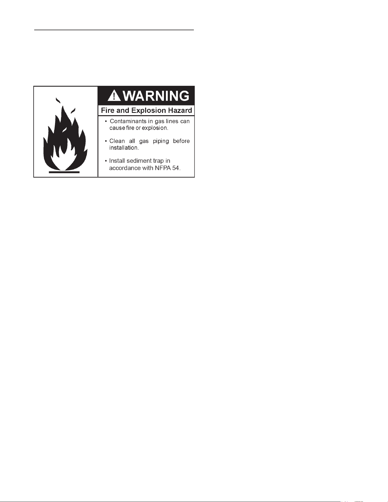
Contaminantsinthegaslinesmaycauseimproperoperationof
thegascontrolvalvethatmayresultinfireorexplosion.Before
attachingthegaslinebesurethatallgaspipeiscleanonthe
inside.Totrapanydirtorforeignmaterialinthegassupplyline,
asedimenttrapmustbeincorporatedinthepiping.Thesediment
trapmustbereadilyaccessible.Installinaccordancewiththe
“GasPiping”section.RefertothecurrenteditionoftheNational
FuelGasCode,ANSIZ223.1/NFPA54ortheNaturalGasand
PropaneInstallationCodeCAN/CSAB149.1.
18
FLAMMABLE
WARNING:
If you do not follow these instructions exactly, a
fire or explosion may result causing property damage, personal
injury or loss of life.
BEFORE LIGHTING: ENTIRE SYSTEM MUST BE FILLED WITH WATER AND AIR PURGED FROM ALL LINES
A.
C.
D.
WHAT TO DO IF YOU SMELL GAS
Do not try to light any appliance.
Do not touch any electric switch; do not use any
phone in your building.
Immediately call your gas supplier from a neighbor's
phone. Follow the gas supplier's instructions.
If you cannot reach your gas supplier, call the fire
department.
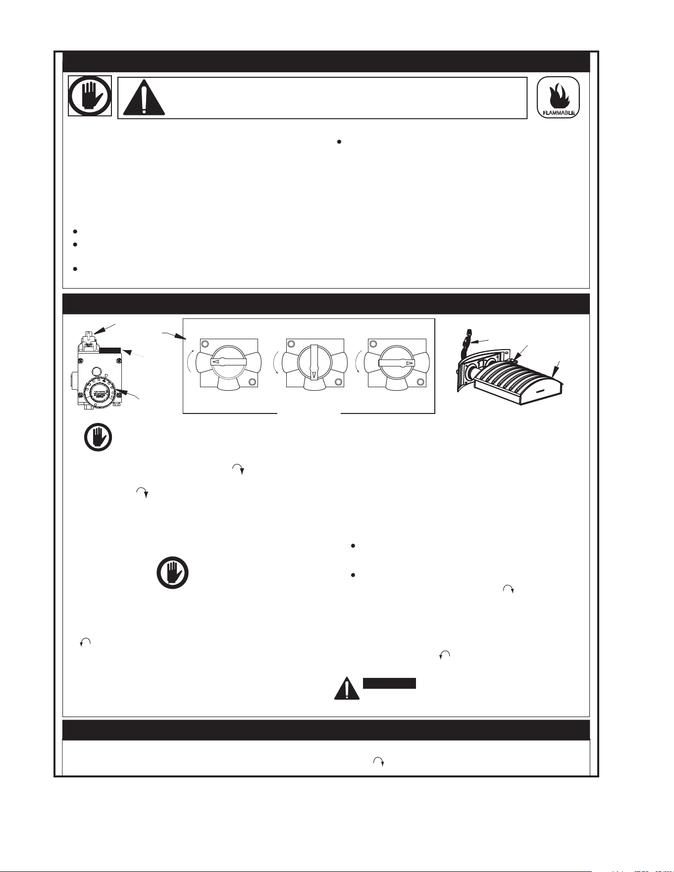
LIGHTING INSTRUCTIONS
TOP KNOB
FIGURE 'A'
"OFF" POSITION
OFF
ON
PILOT
FIGURE 'B'
"PILOT" POSITION
OFF
ON
PILOT
FIGURE 'C'
"ON" POSITION
OFF
ON
PILOT
1. 2.
TO TURN OFF GAS TO APPLIANCE
S e t the t hermosta t to lowest se tting. Push gas control knob down slightly and turn clock-
wise to 'OFF'. Do not force. SEE FIGURE 'A'.
1.
10.
11.
12.
13.
2.
3.
5.
6.
7.
8.
9.
STOP! Read the safety information
above on this label.
Push the gas control knob down slightly and turn
clockwise to "OFF". SEE FIGURE 'A'.
NOTE: Knob cannot be turned from "PILOT" to "OFF"
unless knob is pushed down slightly. Do not force.
Wait five (5) minutes to clear out any gas. If you
then smell gas, STOP! Follow "B" in the
safety information above on this label. If
you do not smell gas,
go to next step.
This unit is equipped with a push button pilot ignitor,
on the gas control.
Continue to hold the gas control knob down for about
one (1) minute after the pilot is lit. Release the gas
control knob and it will pop back up. Pilot should
remain lit. If it goes out , repeat step (3) through (9).
It may take several minutes for air to clear the lines
before the pilot will light.
If knob does not pop up when released, stop and
immediately call your service technician or gas
supplier.
If the pilot will not stay lit after several tries,
turn the gas control knob clockwise to 'OFF' and
call your service technician or gas supplier.
SEE FIGURE 'A'
DANGER: Hotter water increases the risk
of scald injury. Consult the instruction
manual before changing temperature.
At arm's length away, turn gas control knob
counterclockwise to 'ON'. SEE FIGURE 'C'.
Set thermostat to desired setting.
Remove the outer door located below
the gas control unit.
4.
which is used to light the pilot. Locate the ignitor
Turn gas control knob counterclockwise
to "PILOT". SEE FIGURE 'B'.
Replace the outer door.
DIAL
KNOB
GAS CONTROL
THERMOSTAT
GAS CONTROL
PIEZO
IGNITOR
GENERATOR
The pilot is located on the left front corner of the burner.
It can be located by looking through the sight glass to
the left while pressing the piezo ignitor button
several times. Look for a spark at the pilot location
.
Once the pilot has been found, push the gas knob
all the way down. Immediately press the pilot ignitor
button rapidly (4) to (5) times. If the pilot does not
light, repeat step (3) through (9).
This appliance has a pilot which is lit by a piezo-
electric spark gas ignition system. When lighting
the pilot, follow these instructions exactly.
B.
BEFORE LIGHTING smell all around the
appliance area for gas. Be sure to smell next
to the floor because some gas is heavier than
air and will settle on the floor.
Use only your hand to push down or turn the gas
control knob. Never use tools. If the knob will
not push down or turn by hand, don't try to repair
it, call a qualified service technician. Force or
attempted repair may result in fire or explosion.
Do not use this appliance if any part has been
under water. Immediately contact a qualified
installer or service agency to replace a flooded
water heater. Do not attempt to repair the unit!
It must be replaced!
Set the thermostat to the lowest setting by turning
thermostat dial fully clockwise until it stops.
FOR YOUR SAFETY READ BEFORE LIGHTING
FIGURE "D"
PILOT
MAIN BURNER
THERMOCOUPLE &
BURNER TUBE
19
START UP CONDITIONS
DRAFT HOOD OPERATION
Check draft hood operation by performing a worst case
depressurization of the building. With all doors and windows
closed, and withallairhandlingequipmentandexhaust fans
operating such as furnaces, clothes dryers, range hoods and
bathroomfans,amatchameshouldstillbedrawnintothedraft
hoodofthewaterheaterwithitsburnerring.Iftheameisnot
drawn toward the draft hood, shut off water heater and make
necessaryairsupplychangestocorrect.
CONDENSATION
Whenever the water heater is filled with cold water, some
condensatewillformwhiletheburnerison.Awaterheatermay
Shortrepeatedheatingcyclescausedbysmallhotwaterusescan
causetemperatures atthe pointof usetoexceedthethermostat
settingbyupto30°F(16.7°C).Ifyouexperiencethistypeofuse
you should consider using lower temperature settings to reduce
scaldhazards.
Anywaterheater’sintendedpurposeistoheatwater.Hotwater
isneededforcleansing,cleaning,andsanitizing(bodies,dishes,
clothing).Untempered hot water can present a scald hazard.
Dependingonthetimeelement,andthepeopleinvolved(adults,
children, elderly, inrm, etc.) scalding may occur at different
temperatures.
HOTTERWATERCANSCALD:Waterheatersareintendedtoproduce
hotwater.Waterheatedtoatemperaturewhichwillsatisfyspace
heating,clotheswashing,dishwashing,andothersanitizingneeds
canscaldandpermanentlyinjureyouuponcontact.Somepeople
aremorelikelytobepermanentlyinjuredbyhotwaterthanothers.
Theseincludetheelderly,children,theinrm,orphysically/mentally
handicapped.Ifanyoneusinghotwaterinyourhometsintooneof
thesegroupsorifthereisalocalcodeorstatelawrequiringacertain
temperaturewateratthehotwatertap,thenyoumusttakespecial
precautions. In addition to using the lowest possible temperature
settingthatsatisesyourhotwaterneeds,ameanssuchasamixing
valveshouldbeusedatthehotwatertapsusedbythesepeopleor
atthewaterheater.Mixingvalvesareavailableatplumbingsupplyor
hardwarestores,seeFigure6.Followmanufacturer’sinstructionsfor
installationofthevalves.Beforechangingthefactorysettingonthe
thermostat,readthe“TemperatureRegulation”sectioninthismanual,
seeFigures17and18.
TEMPERATURE REGULATION
FOR YOUR INFORMATION
appeartobeleakingwheninfactthewateriscondensation.This
usuallyhappenswhen:
a.Anewwaterheaterislledwithcoldwaterforthersttime.
b.Burninggasproduceswatervaporinwaterheaters,par ticularly
highefciencymodelswhereuetemperaturesarelower.
c.Largeamountsofhotwaterareusedinashorttimeandthe
rellwaterinthetankisverycold.
Moisturefromtheproductsofcombustioncondenseonthecooler
tanksurfacesand form drops ofwaterwhich may fall ontothe
burnerorotherhotsurfacestoproducea“sizzling”or“frying”noise.
Excessive condensation can cause pilot outage due to water
runningdownthefluetubeontothemainburnerandputtingout
thepilot.
Neverallowsmallchildrentouseahotwatertap,ortodrawtheirown
bathwater.Neverleaveachildorhandicappedpersonunattended
inabathtuborshower.
NOTE:Awatertemperaturerangeof120°F-140°F(49°C-60°C)is
recommendedbymostdishwashermanufacturers.
Thethermostatofthiswaterheaterhasbeenfactorysetatitslowest
position (PILOT LIGHTING). It is adjustable and must be reset to
the desired temperature setting to reduce the risk of scald injury.
Themark(
)indicativeofapproximately120°F(49°C)ispreferred
startingpoint.SomeStateshavearequirementforalowersetting.
Turn the water temperature dial clockwise (
) to decrease the
temperature,orcounterclockwise(
)toincreasethetemperature.
Shouldoverheatingoccurorthegassupplyfailtoshutoff,turnoffthe
manualgascontrolvalvetothewaterheater.
FIGURE 17.
Temperature Time to Produce 2nd & 3rd
Nearly instantaneous
D = APPROX.160°F (71°C) About 1/2 second
C = APPROX.150°F (65°C) About 1-1/2 seconds
B = APPROX.140°F (60°C) Less than 5 seconds
A = APPROX.130°F (54°C) About 30 seconds
= APPROX.120°F (49°C) More than 5 minutes
LOW = APPROX.100°F (37.8°C) - - - - - - - -
Setting Degree Burns on Adult Skin
VERY HOT = APPROX. 181°F (83°C)
FIGURE 18.
20
CHECKING GAS INPUT
Withthisheaterinoperation,determinewhetheritisreceivingthe
fullratedinputofgas.Thismaybedonebytimingthegasmeter
andmeasuringgaspressurewithagaugeormanometer.Whenthe
heaterisoperatingatfullcapacity(fullgasinput)itshouldconsume
approximately1cubicfootofgasinthetimeshowninTable5.
TABLE 5. INPUT CHECK TIME REQUIRED
TO CONSUME 1 CU. FT. OF GAS
Model Type of Gas
BTU Per
Cu. Ft.
Approx. Time Required To
Consume 1 Cu. Ft. of Gas
BCN375
BCN3100
Natural 1050 50.3sec.
Use this formula to “clock” the meter. Be sure that other gas
consumingappliancesarenotoperatingduringthisinterval.
3,600XH=Btu/Hr
T
T=Timeinsecondsneededtoburnonecubicfootofgas.
H=HeatingvalueofgasinBtu’spercubicfootofgas.
Btu/Hr=Actualheaterinputrate.
Example:
T=50.3seconds/ft
3
H=1,050Btu/ft
3
(naturalgas)
Btu/Hr=?
3,600X1,050=75,100Btu/Hr(22.0kW)
50.3
Comparetheactualinputratetothatgivenontheheater’srating
plate.Intheexample,theBCN3100fullinputrateshouldbe75,100
Btu/Hrfornaturalgas.
Because of the suddenness and amount of water, condensation
watermaybediagnosedasa“tankleak”.Afterthewaterinthetank
warmsup(about1-2hours),theconditionshoulddisappear.
Do not assume the water heater is leaking until there has been
enoughtimeforthewaterinthetanktowarmup.
Anundersizedwaterheaterwillcausemorecondensation.Thewater
heatermustbesizedproperlytomeetthefamily’sdemandsforhot
waterincludingdishwashers,washingmachinesandshowerheads.
Excessivecondensationmaybenoticedduringthewinterandearly
springmonthswhenincomingwatertemperaturesareattheirlowest.
Goodventingisessentialforagasredwaterheatertooperateproperly
aswellastocarryawayproductsofcombustionandwatervapor.
SMOKE/ODOR
Itisnotuncommontoexperienceasmallamountofsmokeandodor
duringtheinitialstart-up.Thisisduetoburningoffofoilfrommetal
parts,andwilldisappearinashortwhile.
STRANGE SOUNDS
Possiblenoisesduetoexpansionandcontractionofsomemetal
partsduringperiodsofheat-upandcool-downdonotnecessarily
representharmfulordangerousconditions.
Condensationcausessizzlingandpoppingwithintheburnerarea
duringheatingandcoolingperiodsandshouldbeconsiderednormal.
See“Condensation”inthissection.
OPERATIONAL CONDITIONS
SMELLY WATER
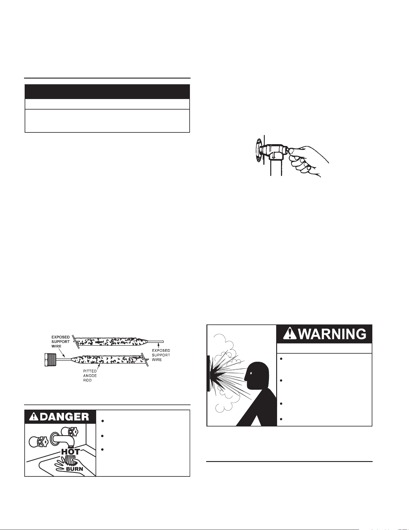
Ineachwaterheaterthereisinstalledatleastoneanoderodfor
corrosionprotectionofthetank.Certainwaterconditionswillcausea
reactionbetweenthisrodandthewater.Themostcommoncomplaint
associatedwiththeanoderodisoneofa“rotteneggsmell”inthe
hotwater.Thisodorisderivedfromhydrogensuldegasdissolved
inthewater.Thesmellistheresultoffourfactorswhichmustallbe
presentfortheodortodevelop:
a.Aconcentrationofsulfateinthesupplywater.
b.Littleornodissolvedoxygeninthewater.
c.A sulfate reducing bacteria which has accumulated withinthe
waterheater(thisharmlessbacteriaisnontoxictohumans).
d.Anexcessofactivehydrogeninthetank.Thisiscausedbythe
corrosionprotectiveactionoftheanode.
Smellywatermaybeeliminatedorreducedinsomewaterheater
modelsbyreplacingtheanode(s)withoneoflessactivematerial,
andthenchlorinatingthewaterheatertankandallhotwaterlines.
Contactthelocalwaterheatersupplierorservicetechnicianfor
furtherinformationconcerning anAnodeReplacement Kitand
thischlorinationtreatment.
Ifthesmellywaterpersistsaftertheanodereplacementandchlorination
treatment,wecanonlysuggestthatchlorinationoraerationofthewater
supplybeconsideredtoeliminatethewaterproblem.
Do not remove the anode leaving the tank unprotected. By doing
so, all warranty on the water heater tank is voided.
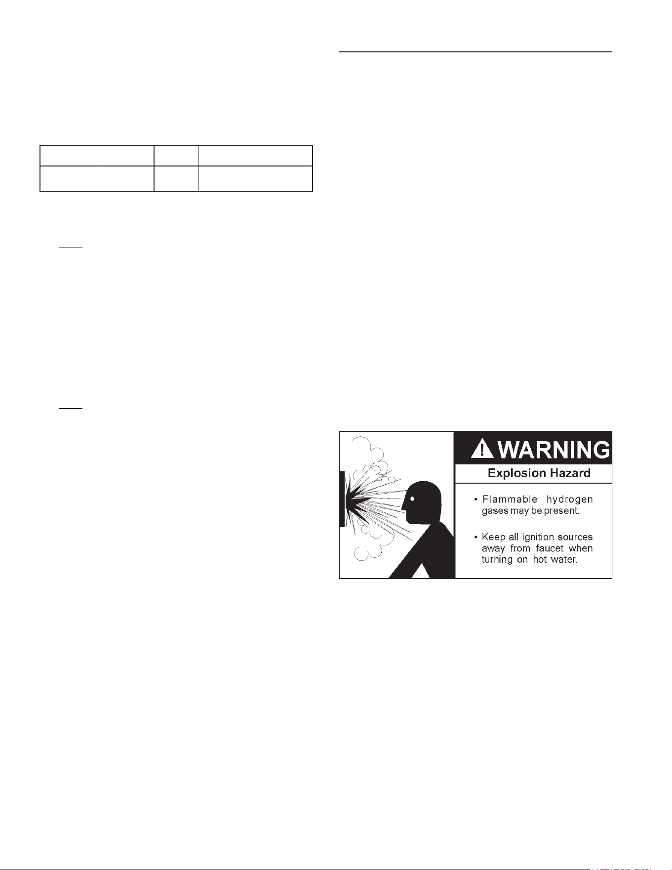
“AIR” IN HOT WATER FAUCETS
HYDROGEN GAS: Hydrogen gas can be produced in a hot
watersystemthathasnotbeenusedforalongperiodoftime
(generally two weeks or more). Hydrogen gas is extremely
ammable and explosive. To prevent the possibility of injury
undertheseconditions, we recommend the hot water faucet,
locatedfarthest away, be openedfor several minutes before
anyelectricalapplianceswhichareconnectedtothehotwater
systemareused(suchasadishwasherorwashingmachine).If
hydrogengasispresent,therewillprobablybeanunusualsound
similartoairescapingthroughthepipeasthehotwaterfaucet
isopened.Theremustbenosmokingoropenamenearthe
faucetatthetimeitisopen.
HIGH WATER TEMPERATURE SHUT OFF SYSTEM
Thiswater heateris equipped with anautomaticgasShut-off
system.Thissystemworkswhenhighwatertemperaturesare
present.ThehightemperatureShut- offisbuiltintothegasc ontrol
valve.Itautomaticallyresetswhenthetemperatureatthermostat
leveldropsbelow120degreesFahrenheit.
21
PERIODIC MAINTENANCE
VENTING SYSTEM INSPECTION
Atleastonceayearavisualinspectionshouldbemadeoftheventing
system.Youshouldlookfor:
1.Obstructions which could cause improper venting.The
combustionandventilationairowmustnotbeobstructed.
2. Damage or deterioration which could cause improperventing
orleakageofcombustionproducts.
3. Rustedakesaroundtopofwaterheater.
Besurethe ventpiping is properlyconnectedto preventescape
ofdangerousuegaseswhichcouldcausedeadlyasphyxiation.
Obstructionsanddeteriorated ventsystems may presentserious
healthriskorasphyxiation.
Chemicalvaporcorrosionoftheueandventsystemmayoccur
ifairforcombustioncontainscertainchemicalvapors.Spraycan
propellants, cleaning solvents, refrigerator and air conditioner
refrigerants,swimmingpoolchemicals,calciumandsodiumchloride,
waxes,bleachandprocesschemicalsaretypicalcompoundswhich
arepotentiallycorrosive.
Ifafterinspectionofventsystemyoufoundsootingordeterioration,
somethingiswrong.Callthelocalgasutilitytocorrectproblemand
cleanorreplacetheueandventingbeforeresumingoperationof
waterheater.
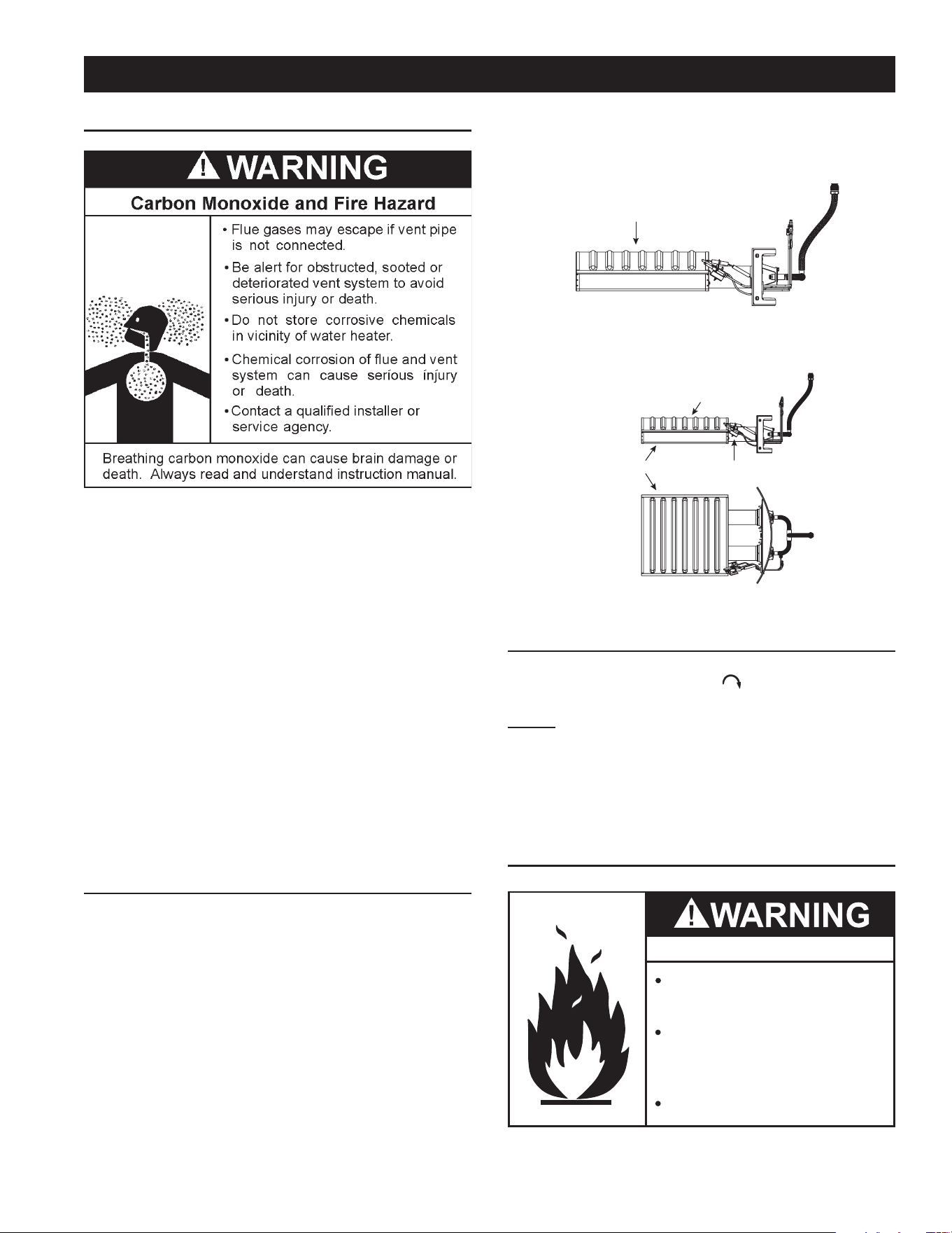
BURNER INSPECTION
Flood damage to a water heater may not be readily visible or
immediatelydetectable.However,overaperiodoftimeaooded
water heater will create dangerous conditions which can cause
DEATH, SERIOUS BODILY INJURY, OR PROPERTY DAMAGE.
Contactaqualiedinstallerorservicetechniciantoreplaceaooded
waterheater.Donotattempttorepairtheunit!Itmustbereplaced!
Atleastonceayearavisualinspectionshouldbemadeofthemain
burnerandpilotburner,seeFigure19.Inspectburneramesthrough
viewport.Flamesshouldbeverysmallwithabluehazeandsmall
amountsofyellowororangeattheedges.Afterseveralminutesof
operationtheburnerscreenmayglowred.
Youshouldcheckfor sooting. Soot is not normal and will impair
propercombustion.
Sootbuild-upindicatesaproblemthatrequirescorrectionbefore
furtheruse.Turn“OFF”gastowaterheaterandleaveoffuntil
repairs are made, because failure to correct the cause of the
sooting can result in a re causing death, serious injury, or
propertydamage.
Flame Characteristics
Correct Flame
Red/Orange
FIGURE 19.
Natural Gas (Low Nox)
Burner Door Assembly
Use brush on this surface
Burner Pilot Assembly
FIGURE 20.
BURNER CLEANING
Ifinspectionoftheburnershowsthatcleaningisrequired,turn
the gas control knob clockwise (
)to the “OFF”position,
depressingslightly.
NOTE: The knob cannot be turned from “PILOT” to “OFF”
unless knob is depressed slightly. DO NOT FORCE.
Checktheburnertoseeifit’sdirtyorclogged.Theburnermaybe
cleanedwithasoftpaintbrush,seeFigure20.Donotuseawire
brushoranytoolthatmaydamagetheburnerscreen.Important:Do
notusetheburneriftheburnerscreenisdamaged.NOTE:Damage
mayberipsorholesintheburnerscreen.Discolorationisnormal.
HOUSEKEEPING
Fire and Explosion Hazard
Do not obstruct combustion air
openings at the bottom of the
water heater.
Do not use or store flammable vapor
products such as gasoline, solvents
or adhesives in the same room or area
near water heater or other appliance.
Can cause serious injury or death.
Vacuum aroundbaseof water heater fordust,dirt, and lint ona
regularbasis.
22
WhencheckingtheTemperature-PressureReliefValveoperation,
makesurethat(1)nooneisinfrontoforaroundtheoutletofthe
Temperature-PressureReliefValvedischargeline,and(2)thatthe
waterdischargewillnotcauseanypropertydamage,asthewater
maybeextremelyhot.Usecarewhenoperatingvalveasthevalve
maybehot.
Tocheckthereliefvalve,lifttheleverattheendofvalveseveraltimes,
seeFigure21.Thevalveshouldseatproperlyandoperatefreely.
Ifaftermanuallyoperatingthevalve,itfailstocompletelyresetand
continuestoreleasewater,immediatelyclosethecoldwaterinlet
tothewaterheateranddrainthewaterheater,seeDrainingAnd
Flushingonpage24.ReplacetheTemperature-PressureReliefValve
with a properly rated/sized new one, see Temperature-Pressure
ReliefValveonpage11forinstructionsonreplacement.
DISCHARGE PIPE
TEMPERATURE-PRESSURE
RELIEF VALVE
FIGURE 21.
IftheTemperature-PressureReliefValveonthewaterheaterweeps
ordischargesperiodically,thismaybeduetothermalexpansion.
NOTE:Excessivewaterpressureisthemostcommoncauseof
Temperature-Pressure Relief Valve leakage. Excessive water
systempressureismostoftencausedby“thermalexpansion”
ina“closedsystem.”SeeClosedWaterSystemsandThermal
Expansiononpage11.TheTemperature-PressureReliefValve
isnotintendedfortheconstantreliefofthermalexpansion.
Temperature-Pressure Relief Valve leakage due to pressure
build up in a closed system that does not have a thermal
expansion tank installed is not covered under the limited
warranty. Thermal expansion tanks must be installed on all
closedwatersystems.
DO NOT PLUG THE TEMPERATURE-PRESSURE RELIEF
VALVE OPENING. THIS CAN CAUSE PROPERTY DAMAGE,
SERIOUS INJURY OR DEATH.
Explosion Hazard
Temperature-Pressure Relief Valve
must comply with ANSI Z21.22-
CSA 4.4 and ASME code.
Properly sized temperature-
pressure relief valve must be
installed in opening provided.
Can result in overheating and
excessive tank pressure.
Can cause serious injury or death.
RECOMMENDED PROCEDURE FOR PERIODIC
REMOVAL OF LIME DEPOSITS FROM TANK TYPE
COMMERCIAL WATER HEATERS
Theamountofcalciumcarbonate(lime)releasedfromwateris
indirectproportiontowatertemperatureandusage,seechart.
Thehigherthewatertemperatureorwaterusage,themorelime
depositsaredroppedoutofthewater.Thisisthelimescalewhich
formsinpipes,heatersandoncookingutensils.
INSTALLEDINSUITABLEAREA:Toinsuresufficientventilation
and combustion air supply, proper clearances from the water
heatermustbemaintained.SeeFactstoConsiderAboutThe
Location section. Combustible materials such as clothing,
cleaningmaterials,orflammableliquids,etc.mustnotbeplaced
againstoradjacenttothewaterheaterwhichcancauseafire.
ANODE ROD INSPECTION
Property Damage Hazard
•
Avoid water heater damage.
•
Inspection and replacement of anode rod required.
CAUTION
Theanoderodisusedtoprotectthetankfromcorrosion.Mosthot
watertanksareequippedwithananoderod.Thesubmergedrod
sacricesitself toprotect thetank.Insteadofcorroding thetank,
waterionsattackandeatawaytheanoderod.Thisdoesnotaffect
water’stasteorcolor.Therodmustbemaintainedtokeepthetank
inoperatingcondition.
Anodedeteriorationdependsonwaterconductivity,notnecessarily
watercondition.Acorrodedorpittedanoderodindicateshighwater
conductivityandshouldbecheckedand/orreplacedmoreoftenthan
ananoderodthatappearstobeintact.Replacementofadepleted
anoderodcanextendthelifeofyourwaterheater.Inspectionshould
beconductedbyaqualiedservicetechnician,andataminimum
shouldbecheckedannuallyafterthewarrantyperiod.
Articially softened water is exceedingly corrosive because the
processsubstitutessodiumionsformagnesiumandcalciumions.
The use of a water softener may decrease the life of the water
heatertank.
Theanoderodshouldbeinspectedafteramaximumofthreeyears
andannuallythereafteruntiltheconditionoftheanoderoddictates
itsreplacement.
NOTE: Articially softened water requires the anode rod to be
inspectedannually.
Thefollowingaretypical(butnotall)signsofadepletedanoderod:
• Themajorityoftherodsdiameterislessthan3/8”.
• Signicantsectionsofthesupportwire(approx.1/3ormoreof
theanoderod’slength)arevisible.
TEMPERATURE-PRESSURE RELIEF VALVE TEST
Burn hazard.
Hot water discharge.
Keep clear of Temperature-
Pressure Relief Valve
discharge outlet.
ItisrecommendedthattheTemperature-PressureReliefValve
should be checked to ensure that it is in operating condition
every6months.
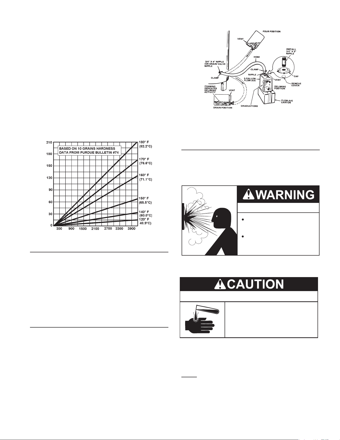
23
Limeaccumulationnotonlyreducesthelifeoftheequipmentbut
alsoreducesefciencyoftheheaterandincreasesfuelconsumption.
The usage of water softening equipment greatly reduces the
hardnessofthewater.However,thisequipment doesnotalways
removeallofthehardness(lime).Forthisreasonitisrecommended
thataregularschedulefordelimingbemaintained.
Thetimebetweencleaningwillvaryfromweekstomonthsdepending
uponwaterconditionsandusage.
Thedepthoflimebuildupshouldbemeasuredperiodically.Heaters
equippedwithcleanouts will have about2”of lime buildup when
theleveloflimehasreachedthebottomofthecleanoutopening.A
schedulefordelimingshouldthenbesetup,basedontheamount
oftimeitwouldtakefora1”buildupoflime.Itisrecommendedthat
thewaterheaterinitiallybeinspectedafter6months.
Example1:
Initialinspectionafter6monthsshows1/2”oflimeaccumulation.
Therefore,theheatershouldbedelimedonceayear.
Example2:
Initialinspectionafter6monthsshows2”oflimeaccumulation.
Therefore,theheatershouldbedelimedevery3months.
FIGURE 22.
DELIMING SOLVENTS
UN•LIMEis recommendedfor deliming.UN•LIMEisapatented
foodgradeacidwhichissafetohandleanddoesnotcreatethe
harmfulfumeswhichareassociatedwithotherproducts.
UN•LIMEmaybeobtainedfromyourdealer,distributororwater
heatermanufacturer.OrderPartNumber9005416105,1gallon,
packed 4 gallons per case or Part Number 9005417105, 5
galloncontainer.
NOTE:Un•LimeisnotavailableforuseinCanada.
Hydrochloric base acids are not recommended for use on glass
lined tanks.
Observehandlinginstructionsonlabelofproductbeingused.
TANK CLEANOUT PROCEDURE
Thefollowingpracticeswillensurelongerlifeandenabletheunitto
operateatitsdesignedefciency:
1. Onceamonththeheatershouldbeushed.Openthedrainvalve
andallowtwogallonsofwatertodrainfromtheheater.Inletwater
valveshouldremainopentomaintainpressureintank.
2. Acleanoutopeningisprovidedforperiodiccleaningofthetank.
Gasmustbeshutoffandheaterdrainedbeforeopeningcleanout.
Tocleanheaterthroughcleanoutopening,proceedasfollows:
1. Drainheater.
2. Removeoutercoverplatefromlowersideofheaterjacket.
3. Removesix(6)hexheadscrewssecuringtankcleanoutplate
andremoveplate.
4. Removelime,scale,orsedimentusingcarenottodamagethe
glasslining.
5. Inspect cleanout plate gasket, if new gasket is required, see
replacementpartslistforitemnumber.
6. Installcleanoutplate.Besuretodrawplateuptightbytightening
screwssecurely.
7. Replaceouterjacketcoverplate.
FIGURE 23.
9. In some water areas the sediment might not be removed
bythismethod andmay result inthe water heatermaking
rumblingorboilingnoises.Todissolveandremovethesemore
stubborn mineral deposits, UN•LIME Professional Delimer
shouldbeused.
DELIMING USING FLO-JUG METHOD
UN•LIMEin the5 gallonsizeisrecommendedfordelimingof all
models. Contact your local dealer,distributor or, water heater
manufacturer.
PREPARE THE WATER HEATER
TodelimethewaterheaterusingtheFlo-Jugmethod,rstprepare
theheaterfordeliming.
Explosion Hazard
Flammable hydrogen gases
may be present.
Keep all ignition sources away
from faucet when turning on
hot water.
Donotsmokeorhaveopenameorsparksinvicinityofheater.Do
notmixUN•LIMEwithotherchemicals.Donotallowcontactwith
magnesium,aluminumorgalvanizedmetals.
Chemical Hazard
• Product contains phosphoric acid.
• Keep out of reach of children.
• Use rubber or neoprene gloves.
UN•LIMEcontainsphosphoricacid.Incaseofexternalcontact,
flushwithcoolwater.Ifirritationpersists,getmedicalattention.If
swallowed,give1or2glassesofwaterormilkandcallphysician.
Get immediatemedicalattention for eyes.Keepoutof reach
ofchildren.
NOTE: THE USE OF RUBBER OR NEOPRENE GLOVES IS
RECOMMENDED, ESPECIALLY IF YOU HAVE ANY OPEN
SORES OR CUTS TO AVOID UNNECESSARY IRRITATION
OR DISCOMFORT.
1. Turnofffueland/orpowersupplytoheater.Also,turnoffpower
toanyelectricaldeviceorequipment,whichisattached,orpart
ofthesystem.
2. Openhotwatersideoffaucetclosesttoheaterandallowwater
torununtilitiscoolenoughtohandlesafely.
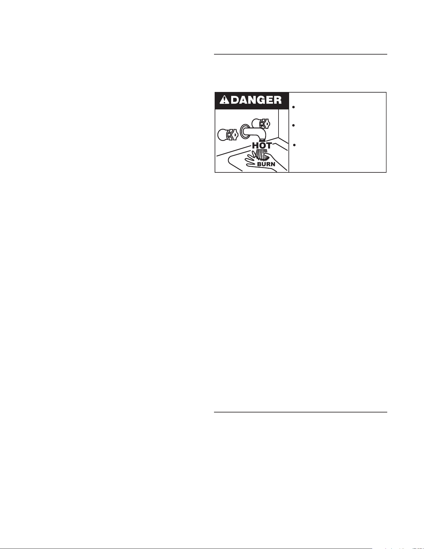
24
3. Closecoldwaterinletvalvetoheater.
4. Connect hose to drain valve at bottom of heater and start
drainingheaterintosuitableoordrainarea.
5. Remove relief valve while heater is draining. NOTE: Do not
replace relief valve until deliming is completed. Relief valve
opening will also act as a vent in case of possible contact
betweenthe delimerandtheanoderod(s), whichmay produce
ammablehydrogen-airmixtures.
6. Ifreliefvalveappearstobelimed-up,placeitinacleanglassor
plasticcontaineradequateinsizesothatyoucanpourenough
UN•LIME®intothecontainertocoverthevalveandallowspace
forfoaming.When foamingstops, run freshcool water intothe
containerandrinsethereliefvalveforafewminutes.
7. If heater does not drain completely after a reasonable length
oftime,turn offthe mainwatersupply valvetostop waterfrom
entering the tank due to a by-pass problem or defective cold
water inlet valve. Also, check for clogged drain valve opening.
HeatermustbecompletelydrainedbeforeintroducingUN•LIME.
8. Removethecleanoutcoverandplaceacleanplasticbucketnext
tothecleanoutopening.
Partiallyopenthecoldwaterinletvalvetoallowtimetoaccomplish
thefollowingandthenclosethevalve.
While the water is being run through the tank, insert a stiff
wire, copper tube attened at one end or an opened wire coat
hangerthroughthe cleanoutopeningand scrapeoutanyloose
depositsofscaleorsediment.Thisisaneconomicalwaytoavoid
unnecessaryusageofthedelimingsolution.
Repeattheopeningandclosingofthecoldwaterinletvalveas
necessary but be sure the heater is completely drained when
readytointroducetheUN•LIME.
Upon completion, reinstall the cleanout cover and use a new
cleanoutcovergasket(partnumber9004099215).
Removethedrainvalve.
9. Install the long plastic male adapter insert tting into the drain
valve opening of heater after applying Teon tape or paste to
threads. Tighten rmly by hand and use wrench or adjustable
plierstocheckforsecureconnection.Donotovertightentoavoid
damagetothreadsandttings.
PREPARE THE UP-N-DOWN TRANSFER KIT
ThenextstepisthepreparationontheUp-N-DownTransferKit,if
youhavenotalreadydoneso:
1. Withthe5gallonUp-N-Downcontainerintheverticalposition,unscrew
theplasticventcapinthehandleandpiercetheplasticmembrane
overtheventbossunderthecaptoallowthecontainertovent.
Note:If your container doesnot have the ventcapand vent
boss,drilla3/16”(4.76mm)holeinthehandle.Whenyouhave
nisheddelimingyouwillbeabletoplugthisdrilledventwiththe
stainlesssteelscrewthatissuppliedwiththekit.
2. Removethecontainer’scapandcutplasticmembranelocatedin
the3/4”IPTopeningincap.Takecaretonotdamagethethreads.
3. Findthe3/4”maleadapter,applyteontapetothethreadedend
andscrewitintothe3/4”IPTopeninginthecap.
4. Putcapwithmaleadapterbackonthecontainerandslide3/4”
hoseoverendofmaleadapterandfasteninplaceusinghose
clampprovided.
DELIME USING FLO-JUG METHOD
5. Slidethehoseclampoverendofhoseandslidehoseoverthe
maleadapter inthe waterheater drainopeningandsecurein
placeusinghoseclamp.
6. Liftcontainertothe“Pour”Positionbeingcarefultokeeptheventinthe
handleabovetheliquidlevelandpourtheUN•LIMEintotheheater.
7. Lowercontainer,youmayhavetoplacethecontaineronitsempty
cartontopreventtheUN•LIMEfromowingbackintothecontainer.
8. LetUN•LIMEremainintheheaterfor5minutesandthenlower
thecontainertothe“Drain”Position.
9. Delimingactivityis indicatedbyfoamingonthe surfaceof the
UN•LIME.Ifthereisdelimingactivity,repeatsteps6thru8.
Normally,limeremovalwillbecompletedwithinonehour.Severe
build-upoflimemaytakelongerthananhourtocompletedescaling.
Note:TocheckUN•LIMEforcontinueduse,placesomescaleorwhite
chalkinaglasswithasmallamountofUN•LIME.Ifthematerialis
vigorouslydissolvedbytheUN•LIME,itcanbereused;ifnot,the
UN•LIMEshouldbereplaced.
If the temperature-pressure relief valve on the appliance weeps or
dischargesperiodically,thismaybeduetothermalexpansion.Youmay
haveacheckvalveinstalledinthewaterlineorawatermeterwitha
checkvalve.Consultyourlocalwatersupplierorservicetechnicianfor
furtherinformation.Donotplugthetemperature-pressurereliefvalve.
DRAINING AND FLUSHING
Itisrecommended thatthewater heater storagetankbe drained
and ushed every 6 months to reduce sediment buildup. The
waterheatershouldbedrainedifbeingshutdownduringfreezing
temperatures.SeeInstallationConsiderationsinthismanualforthe
locationofthewaterheatercomponentsdescribedbelow.
Burn harzard.
Hot water discharge.
Keep hands clear of drain
valve discharge.
TO DRAIN THE WATER HEATER STORAGE TANK:
1. Turn off the gas supply at the Main Gas Shutoff Valve if the
waterheaterisgoingtobeshutdownforanextendedperiod.
2. Ensurethecoldwaterinletvalveisopen.
3. Openanearbyhotwaterfaucetandletthewaterrununtilthe
waterisnolongerhot.
4. Closethecoldwaterinletvalvetothewaterheater.
5. Connectahosetothewaterheaterdrainvalveandterminate
it to an adequate drain.
6. Openthewaterheater drainvalveandallowallthewaterto
drainfromthestoragetank.
7. Close the water heater drain valve when all water in the
storagetankhasdrained.
8. ClosethehotwaterfaucetopenedinStep4.
9. Ifthewaterheaterisgoingtobeshutdownforanextended
period,thedrainvalveshouldbeleftopen.
TO FLUSH THE WATER HEATER STORAGE TANK:
1. Ensurethecoldwaterinletvalveisopen.
2. Openanearbyhotwaterfaucetandletthewaterrununtilthe
waterisnolongerhot.Thenclosethehotwaterfaucet.
3. Connect a hose to the drain valve and terminate it to an
adequate drain.
4. Ensurethedrainhoseissecuredbeforeandduringtheentire
ushingprocedure. Flushingis performedwith systemwater
pressureappliedtothewaterheater.
5. Openthewaterheaterdrainvalvetoushthestoragetank.
6. Flushthewaterheaterstoragetanktoremovesedimentand
allowthewatertoowuntilitrunsclean.
7. Closethewaterheaterdrainvalvewhenushingiscompleted.
8. Removethedrainhose.
9. Fillthewaterheater-seeFillingTheWaterHeaterinthismanual.
10. Turnon thegas supplyto thewater heaterat theMainGas
ShutoffValve.
11. Allowthewaterheatertocompleteseveralheatingcyclesto
ensureitisoperatingproperly.
SERVICE
Beforecallingforrepairservice,readthe“StartUpConditions”and
“OperationalConditions”foundinthe“ForYourInformation”section
ofthismanual.
Ifaconditionpersistsoryouareuncertainabouttheoperationofthe
waterheatercontactaservicetechnician.Ifyouarenotthoroughly
familiarwithgascodes,yourwaterheater,andsafetypractices,contact
yourgassupplierorqualiedinstallertocheckthewaterheater.
Use the ”Leakage Checkpoints” guide to check a “Leaking”
waterheater.Manysuspected“Leakers”arenotleakingtanks.Often
thesourceofthewatercanbefoundandcorrected.
Readthismanualrst.Thenbeforecheckingthewaterheatermake
surethegassupplyhasbeenturned“OFF”,andneverturnthegas
“ON”beforethetankiscompletelyfullofwater.
Neverusethiswaterheaterunlessitiscompletelylledwithwater.To
preventdamagetothetank,thetankmustbelledwithwater.Watermust
owfromthehotwaterfaucetbeforeturning“ON”gastothewaterheater.
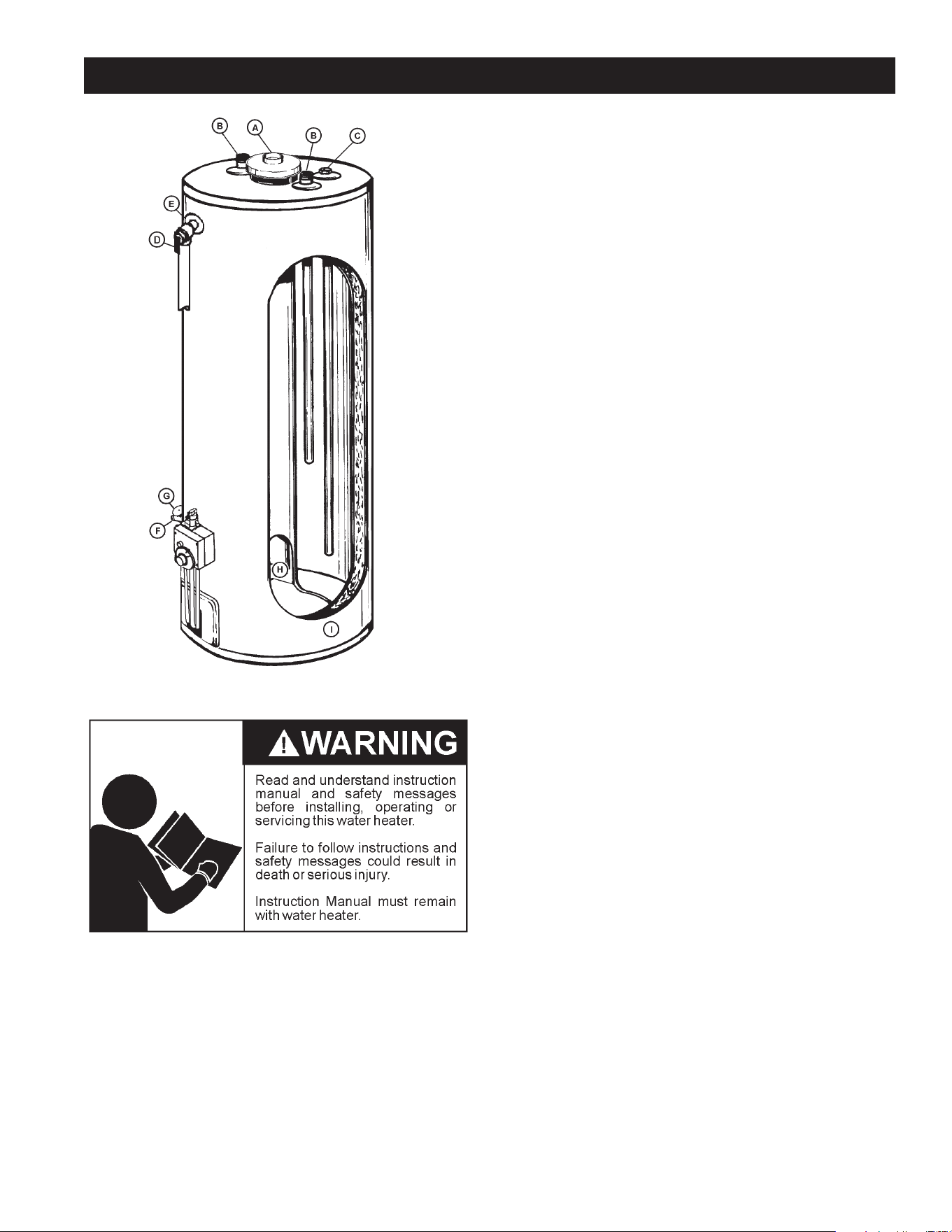
25
LEAKAGE CHECKPOINTS
A. Wateratthedrafthoodiswatervaporwhichhascondensedout
ofthecombustionproducts.Thisiscausedbyaprobleminthe
vent.Contactthegasutility.
B.*Condensationmaybeseenonpipesinhumidweatherorpipe
connectionsmaybeleaking.
C.*Theanoderodttingmaybeleaking.
D.Smallamountsofwaterfromtemperature-pressurereliefvalve
maybeduetothermalexpansionorhighwaterpressureinyour
area.
E.*Thetemperature-pressurereliefvalve may be leaking at the
tanktting.
F.Waterfromadrainvalvemaybeduetothevalvebeingslightly
opened.
G.*Thedrainvalvemaybeleakingatthetanktting.
H.Combustionproductscontainwatervaporwhichcancondense
onthecoolersurfacesofthetank.Dropletsformanddriponto
theburnerorrunontheoor.Thisiscommonatthetimeof
start-upafterinstallationandwhenincomingwateriscold.
I. Waterinthewaterheaterbottomorontheoormaybefrom
condensation,looseconnections,orthereliefvalve.DONOT
replacethewaterheateruntilafullinspectionofallpossiblewater
sourcesismadeandnecessarycorrectivestepstaken.
Leakage from other appliances, water lines, or ground seepage
shouldalsobechecked.
* To check where threaded portion enters tank, insert cotton
swabbetweenjacketopeningandtting.Ifcottoniswet,follow
“DrainingandFlushing”instructionsinthe“PeriodicMaintenance”
sectionandthenremovetting.Putpipedopeorteontapeon
thethreadsandreplace.Thenfollow“FillingtheWaterHeater”
instructionsintheInstallationRequirementssection.
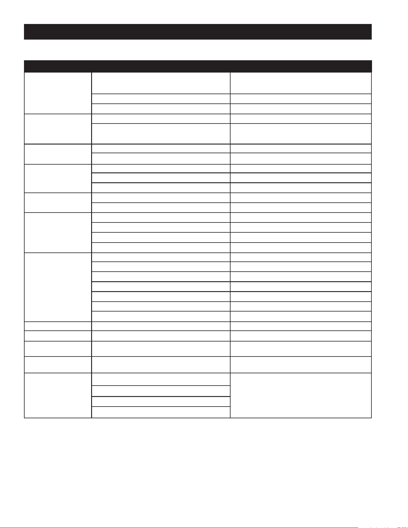
26
TROUBLESHOOTING GUIDELINES
Theseguidelinesshouldbeutilizedbyaqualiedserviceagent.
Problem Cause Solution
WATER LEAKS
Improperlysealed,hotorcoldsupplyconnection,relief
valve,drainvalve,orthermostatthreads.
Tightenthreadedconnections.
Leakagefromotherappliancesorwaterlines. Inspectotherappliancesnearwaterheater.
Condensationofueproducts. RefertoCONDENSATION.
LEAKING T&P VALVE
Thermalexpansioninclosedwatersystem. Installthermalexpansiontank(DONOTplugT&Pvalve).
Improperlyseatedvalve.
Checkreliefvalveforproperoperation
(DONOTplugT&Pvalve).
SMELLY WATER
Highsulfateormineralcontentinwatersupply. Drainandushheaterthoroughly,thenrell.
Bacteriainwatersupply. Chlorinateoraeratewatersupply.
PILOT WILL NOT LIGHT
Gascontrolknobnotpositionedcorrectly. RefertoLIGHTINGINSTRUCTIONS.
Maingassupplyoff. Turnonmaingasshutoffvalve.
Thermocouplemalfunction. Replacepilotassemblyand/orthermocouple.
BURNER WILL NOT
STAY LIT
Thermocouplemalfunction. Replacepilotassemblyand/orthermocouple.
DefectiveGasControl. ReplaceGasControl.
PILOT OUTAGE
Dirtypilotburner. Cleanpilotassembly.
Thermocouplemalfunction. Replacepilotassemblyand/orthermocouple.
DefectiveGasControl. ReplaceGasControl.
Thermocoupletipisnotincontactwithpilotame. Insertthermocouplecorrectly.
NOT ENOUGH
HOT WATER
Heaternotlitorthermostatnoton. RefertoLIGHTINGINSTRUCTIONS.
Thermostatsettoolow. RefertoTEMPERATUREREGULATION.
Heaterundersized. Reducehotwateruse.
Lowgaspressure. Contactyourgassupplier.
Incomingwaterisunusuallycold. Allowmoretimeforheatertore-heat.
Leakinghotwaterpipesorxtures. Haveplumbercheckandrepairleaks.
Hightemperaturelimitswitchactivated. Contactaservicetechniciantodeterminecause.
WATER TOO HOT Thermostatsettoohigh. RefertoTEMPERATUREREGULATION.
WATER HEATER SOUNDS
Condensationdrippingonburner. RefertoCONDENSATION.
SIZZLINGOR
RUMBLING
Sedimentorcalciuminbottomofheatertank.
Cleansedimentfromtank.RefertoDRAINING
instructionsinMaintenancesectionofmanual.
SOOTING Impropercombustion.
Noadjustmentavailable.Contactaservice
techniciantodeterminecause.
VENT GAS ODORS
Lackofsupplyair.
Contactaservicetechniciantodeterminecause.
Improperlyinstalledventpiping.
Downdraft.
Poorcombustion.
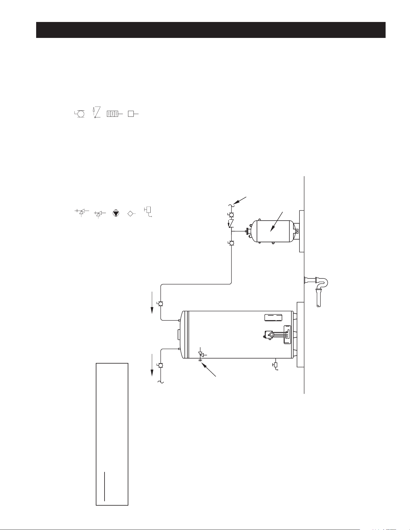
27
WATER PIPING DIAGRAMS
October 2009 | Printed in U.S.A. | © A. O. Smith For Technical Information and Automated Fax Service, call 800-527-1953 or visit www.hotwater.com. AOSCG61130 | PAGE 1 of 1
A. O. Smith Corporation reserves the right to make product changes or improvements without prior notice.
NOTES:
1. Preferred piping diagram.
2. The temperature and pressure relief valve setting shall not exceed pressure rating of any component in the system.
3. Service valves are shown for servicing unit. However, local codes shall govern their usage.
4. The Tank Temperature Control should be wired to and control the pump between the water heater(s) and the storage tank(s).
5. The water heater’s operating thermostat should be set 5 degrees F higher than the Tank Temperature Control.
SINGLE FLUE - (1 UNIT)
LEGEND
TEMPERATURE & PRESSURE
RELIEF VALVE
PRESSURE RELIEF VALVE
CIRCULATING PUMP
TANK TEMPERATURE CONTROL
DRAIN
FULL PORT BALL VALV
E
TEMPERATURE GAGE
WATER FLOW SWITCH
CHECK VALVE
WARNING: THIS DRAWING SHOWS SUGGESTED
PIPING CONFIGURATION AND OTHER DEVICES;
CHECK WITH LOCAL CODES AND ORDINANCES
FOR ADDITIONAL REQUIREMENTS.
FINISHED
FLOOR
HOTCOLD
COLD
EXPANSION
TANK
COLD WATER
SUPPLY
PIPE T&P TO
OPEN DRAIN
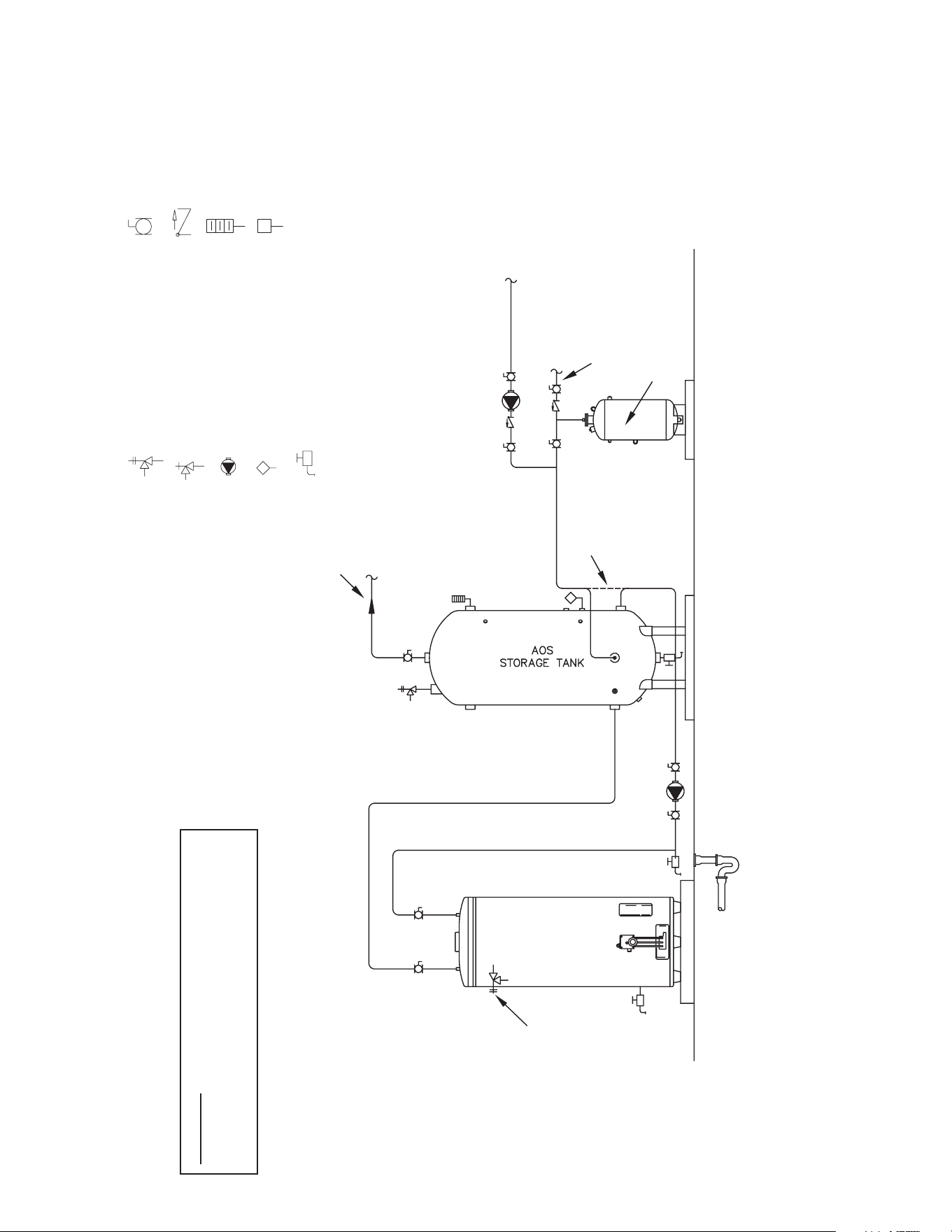
28
October 2009 | Printed in U.S.A. | © A. O. Smith For Technical Information and Automated Fax Service, call 800-527-1953 or visit www.hotwater.com. AOSCG61140 | PAGE 1 of 1
A. O. Smith Corporation reserves the right to make product changes or improvements without prior notice.
NOTES:
1. Preferred piping diagram.
2. The temperature and pressure relief valve setting shall not exceed pressure rating of any component in the system.
3. Service valves are shown for servicing unit. However, local codes shall govern their usage.
4. The Tank Temperature Control should be wired to and control the pump between the water heater(s) and the storage tank(s).
5. The water heater’s operating thermostat should be set 5 degrees F higher than the Tank Temperature Control.
SINGLE FLUE - (1 UNIT) WITH VERTICAL STORAGE TANK
LEGEND
TEMPERATURE & PRESSURE
RELIEF VALVE
PRESSURE RELIEF VALVE
CIRCULATING PUMP
TANK TEMPERATURE CONTROL
DRAIN
FULL PORT BALL VALV
E
TEMPERATURE GAGE
WATER FLOW SWITCH
CHECK VALVE
WARNING: THIS DRAWING SHOWS SUGGESTED
PIPING CONFIGURATION AND OTHER DEVICES;
CHECK WITH LOCAL CODES AND ORDINANCES
FOR ADDITIONAL REQUIREMENTS.
FINISHED
FLOOR
HOTCOLD
EXPANSION
TANK
COLD WATER
SUPPLY
HOT WATER
RETURN FROM
FIXTURES
HOT WATER
TO FIXTURES
ALT. COLD
WATER CONNECTION
PIPE T&P TO
OPEN DRAIN
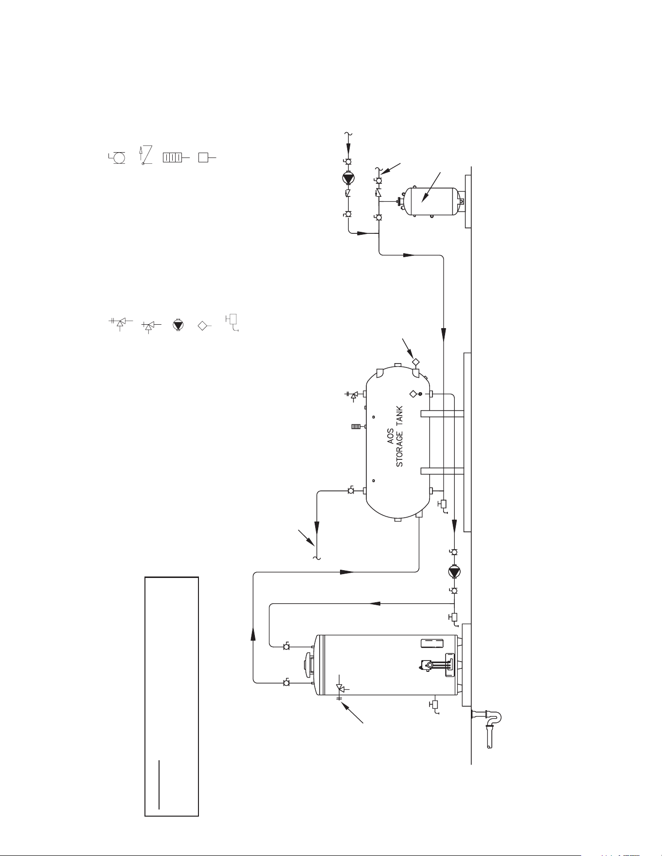
29
October 2009 | Printed in U.S.A. | © A. O. Smith For Technical Information and Automated Fax Service, call 800-527-1953 or visit www.hotwater.com. AOSCG61150 | PAGE 1 of 1
A. O. Smith Corporation reserves the right to make product changes or improvements without prior notice.
NOTES:
1. Preferred piping diagram.
2. The temperature and pressure relief valve setting shall not exceed pressure rating of any component in the system.
3. Service valves are shown for servicing unit. However, local codes shall govern their usage.
4. The Tank Temperature Control should be wired to and control the pump between the water heater(s) and the storage tank(s).
5. The water heater’s operating thermostat should be set 5 degrees F higher than the Tank Temperature Control.
SINGLE FLUE - (1 UNIT) WITH HORIZONTAL STORAGE TANK
LEGEND
TEMPERATURE & PRESSURE
RELIEF VALVE
PRESSURE RELIEF VALVE
CIRCULATING PUMP
TANK TEMPERATURE CONTROL
DRAIN
FULL PORT BALL VALV
E
TEMPERATURE GAGE
WATER FLOW SWITCH
CHECK VALVE
WARNING: THIS DRAWING SHOWS SUGGESTED
PIPING CONFIGURATION AND OTHER DEVICES;
CHECK WITH LOCAL CODES AND ORDINANCES
FOR ADDITIONAL REQUIREMENTS.
FINISHED
FLOOR
HOTCOLD
EXPANSION
TANK
COLD WATER
SUPPLY
HOT WATER
RETURN FROM
FIXTURES
HOT WATER
TO FIXTURES
ALTERNATE
LOCATION
PIPE T&P TO
OPEN DRAIN
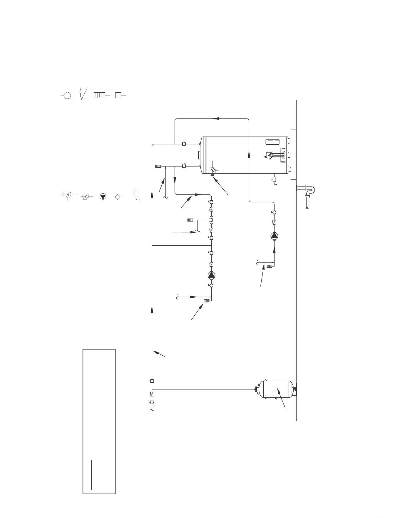
30
October 2009 | Printed in U.S.A. | © A. O. Smith For Technical Information and Automated Fax Service, call 800-527-1953 or visit www.hotwater.com. AOSCG61160 | PAGE 1 of 1
A. O. Smith Corporation reserves the right to make product changes or improvements without prior notice.
NOTES:
1. Preferred piping diagram.
2. The temperature and pressure relief valve setting shall not exceed pressure rating of any component in the system.
3. Service valves are shown for servicing unit. However, local codes shall govern their usage.
4. The Tank Temperature Control should be wired to and control the pump between the water heater(s) and the storage tank(s).
5. The water heater’s operating thermostat should be set 5 degrees F higher than the Tank Temperature Control.
SINGLE FLUE - (1 UNIT) WITH MIXING VALVE TWO TEMPERATURE
LEGEND
TEMPERATURE & PRESSURE
RELIEF VALVE
PRESSURE RELIEF VALVE
CIRCULATING PUMP
TANK TEMPERATURE CONTROL
DRAIN
FULL PORT BALL VALVE
TEMPERATURE GAGE
WATER FLOW SWITCH
CHECK VALVE
WARNING: THIS DRAWING SHOWS SUGGESTED
PIPING CONFIGURATION AND OTHER DEVICES;
CHECK WITH LOCAL CODES AND ORDINANCES
FOR ADDITIONAL REQUIREMENTS.
HOT WATER
RETURN
MINIMUM
10´´ to 12´´
HOT WATER OUTLET
TEMPERED
WATER
RETURN
TEMPERED
WATER
OUTLET
COLD WATER
SUPPLY
LINE
TEMPERATURE
CONTROL
COLDHOT
EXPANSION
TANK
PIPE T&P TO
OPEN DRAIN
219332_AOSCG61160.indd 1 12/9/09 11:24:14 AM
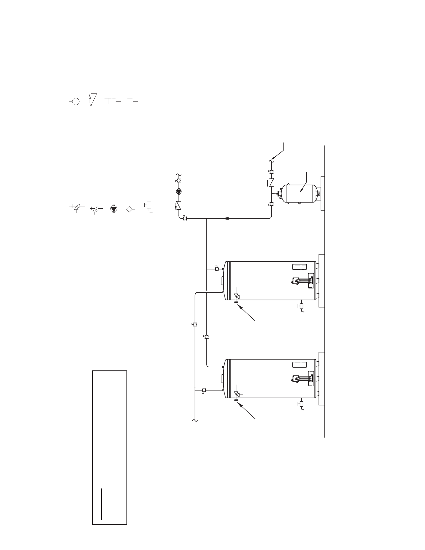
31
October 2009 | Printed in U.S.A. | © A. O. Smith For Technical Information and Automated Fax Service, call 800-527-1953 or visit www.hotwater.com. AOSCG61170 | PAGE 1 of 1
A. O. Smith Corporation reserves the right to make product changes or improvements without prior notice.
NOTES:
1. Preferred piping diagram.
2. The temperature and pressure relief valve setting shall not exceed pressure rating of any component in the system.
3. Service valves are shown for servicing unit. However, local codes shall govern their usage.
4. The Tank Temperature Control should be wired to and control the pump between the water heater(s) and the storage tank(s).
5. The water heater’s operating thermostat should be set 5 degrees F higher than the Tank Temperature Control.
SINGLE FLUE - (2 UNITS)
LEGEND
TEMPERATURE & PRESSURE
RELIEF VALVE
PRESSURE RELIEF VALVE
CIRCULATING PUMP
TANK TEMPERATURE CONTROL
DRAIN
FULL PORT BALL VALV
E
TEMPERATURE GAGE
WATER FLOW SWITCH
CHECK VALVE
WARNING: THIS DRAWING SHOWS SUGGESTED
PIPING CONFIGURATION AND OTHER DEVICES;
CHECK WITH LOCAL CODES AND ORDINANCES
FOR ADDITIONAL REQUIREMENTS.
FINISHED
FLOOR
HOT WATER
TO FIXTURES
HOTCOLDHOT
HOT WATER RETURN
FROM FIXTURES
COLD
COLD WATER
SUPPLY
EXPANSION
TANK
PIPE T&P TO
OPEN DRAIN
PIPE T&P TO
OPEN DRAIN
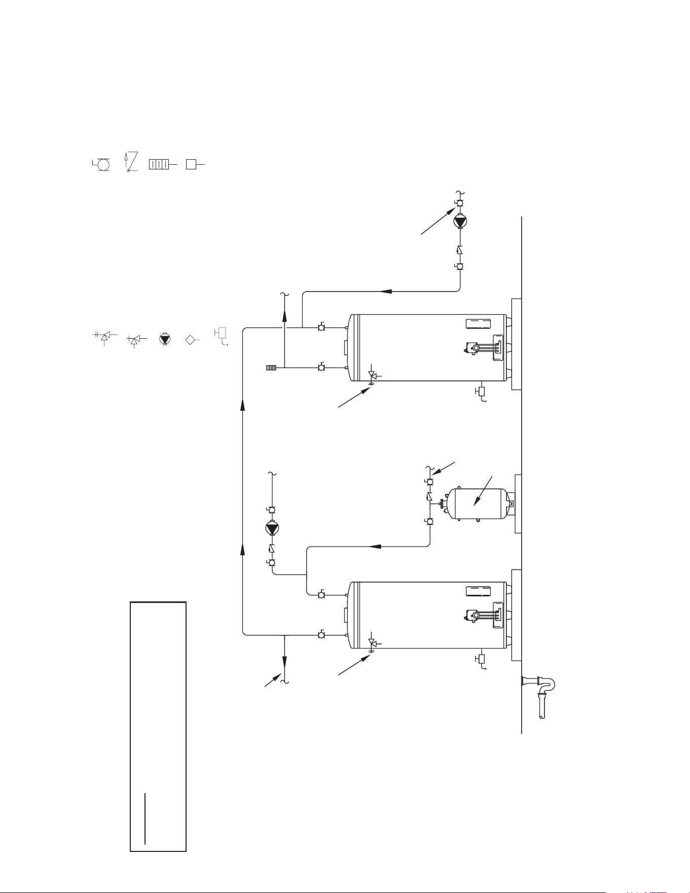
32
October 2009 | Printed in U.S.A. | © A. O. Smith For Technical Information and Automated Fax Service, call 800-527-1953 or visit www.hotwater.com. AOSCG61180 | PAGE 1 of 1
A. O. Smith Corporation reserves the right to make product changes or improvements without prior notice.
NOTES:
1. Preferred piping diagram.
2. The temperature and pressure relief valve setting shall not exceed pressure rating of any component in the system.
3. Service valves are shown for servicing unit. However, local codes shall govern their usage.
4. The Tank Temperature Control should be wired to and control the pump between the water heater(s) and the storage tank(s).
5. The water heater’s operating thermostat should be set 5 degrees F higher than the Tank Temperature Control.
SINGLE FLUE - (2 UNITS) TWO TEMPERATURE ONE PRE-HEATER/ONE BOOSTER HEATER
LEGEND
TEMPERATURE & PRESSURE
RELIEF VALVE
PRESSURE RELIEF VALVE
CIRCULATING PUMP
TANK TEMPERATURE CONTROL
DRAIN
FULL PORT BALL VALV
E
TEMPERATURE GAGE
WATER FLOW SWITCH
CHECK VALVE
WARNING: THIS DRAWING SHOWS SUGGESTED
PIPING CONFIGURATION AND OTHER DEVICES;
CHECK WITH LOCAL CODES AND ORDINANCES
FOR ADDITIONAL REQUIREMENTS.
FINISHED
FLOOR
HOT WATER
TO FIXTURES
HOT WATER RETURN
HOT HOTCOLD
HIGH
TEMPERATURE
RETURN
HIGH
TEMPERATURE
OUTLET
COLD WATER
SUPPLY
EXPANSION
TANK
PIPE T&P TO
OPEN DRAIN
PIPE T&P TO
OPEN DRAIN
BOOSTER
HEATER

33
NOTES

34
NOTES
35
LIMITED WARRANTY
EFFECTIV
E
For
3 Years, in the event of a tank leak, we will repair or, at our
discretion, replace the defective water heater
.
For 1
Year,
in the event of part failure, we will repair or, at our
discretion, replace the defective part
.
We
warrant this product against defects in materials or
w
orkmanship as described in this document if installed within
t
he United States or Canada and provided the product remains
at its original place of installation.
W
arranty coverage begins the date of installation OR the date of
WHA
T'S COVERED
S
ubject to these terms, in the event of defect in materials and/
or
workmanship resulting in a tank leak during the
years
, we will:
•
Replace the water heater should the tank leak.
Subject
to these terms, in the event of a defect in materials and/or
w
orkmanship appearing during the , we will:
•
Repair or, at our discretion, replace any part of the water
heater covered under this limited warranty excluding parts
subject to normal maintenance (Example: non-electronic
Service/labor
, shipping, delivery, installation, handling or any
other costs are not covered at any time under this warranty
.
A
ny replacement part or product will be warranted only for
t
he unexpired portion of the original water heater’s limited
warranty period.
If
an identical model is no longer available due to a change in law,
regulation,
or standard, we will replace the product with one having
comparable
capacity and input. In these instances, the owner will
have
the option of paying the difference between what was paid for
the
original model and the new model with the additional features,
or
receiving a refund of the portion of the purchase price, on a
pro-rata basis allocable to the unexpired portion of the warrant
y.
WHAT'S NOT COVERED
• Problems caused by improper: gas supply line sizing, gas type,
venting, connections, combustion air, voltage, wiring, or fusing
• Failure to follow applicable codes
• Failure to follow printed instructions
• Improper installation, sizing, delivery, or maintenance
• Claims related to rust, noise, smell, or taste of water
• Failure to conduct authorized factory start up if required
• Alterations to the water heater
• Non-outdoor heaters installed outdoors
• Damages due to a failure to allow for thermal expansion
• Heat exchanger failure due to lack of adequate / proper supply
of water
• Heaters moved from their original location
• Service trips to explain proper installation, use, or maintenance
of the product/unit or to describe compliance requirements
under applicable codes and regulations
• Charges related to accessing your heater including but not
limited to door/wall removal, equipment rental, etc.
• Replacement parts after expiration of this warranty
LIMITATIONS
NOTWITHSTANDING ANYTHING ELSE TO THE CONTRARY
,
.YTNARRAW EVISULCXE DNA ELOS RUOY SI SIHT
ALL OTHER WARRANTIES INCLUDING A WARRANTY
OF MERCHANTABILITY OR FITNESS FOR PARTICULAR
PURPOSE ARE EXPRESSLY DISCLAIMED. SELLER SHAL
L
NOT BE LIABLE FOR ANY CONSEQUENTIAL, INCIDENT
AL,
SPECIAL, PUNITIVE OR OTHER INDIRECT DAMAGES. TOTA
L
LIABILITY ARISING AT ANY TIME SHALL NOT EXCEED
THE
PURCHASE PRICE PAID WHETHER BASED ON CONTRACT
,
TORT, STRICT LIABILITY OR ANY OTHER LEGAL THEORY.
SER
VICE INQUIRIES:
For service inquiries call the telephone number listed below
. Be prepared to provide the following information:
name,
address, and telephone number; the model and serial number of the water heater; proof of installation; and a clear description
of the problem.
For your records, fill in the product:
Serial: __________________
_
Model: ___________________
U.S. Customers:
American Water Heaters
500 Princeton Road
Johnson City, TN 37605
800-999-9515
www.americanwaterheaters.com
COMMERCIAL
WATER HEATER
LIMITED WARRANTY

36
P.O.Box1597,JohnsonCity,TN37605
Phone:800-456-9805•Fax:800-999-5210
www.americanwaterheater.com
Copyright©2015AmericanWaterHeaterCompany.Allrightsreserved.
www.americanwaterheater. com
American Water Heater
Johnson City, TN 37605