V1
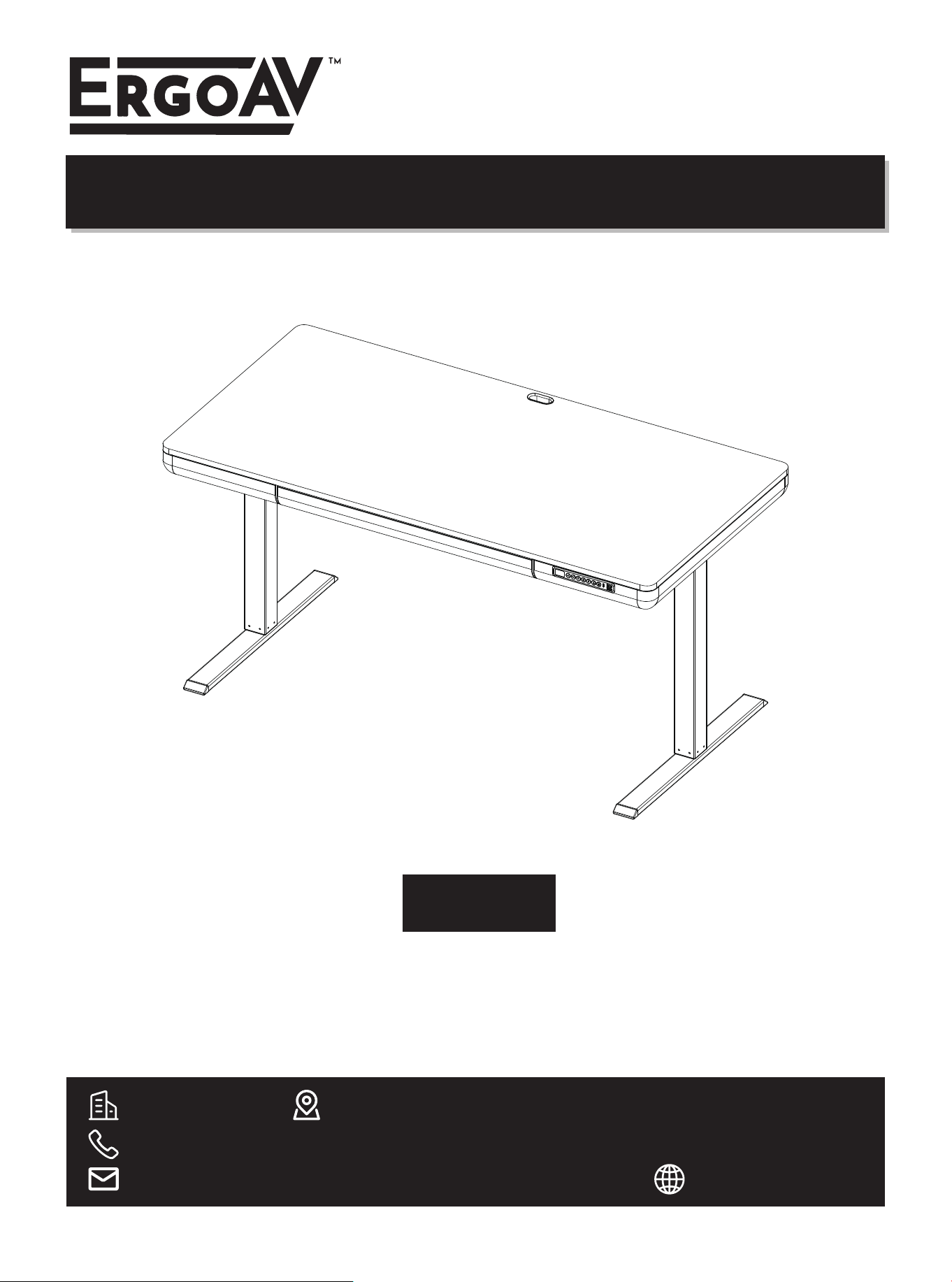
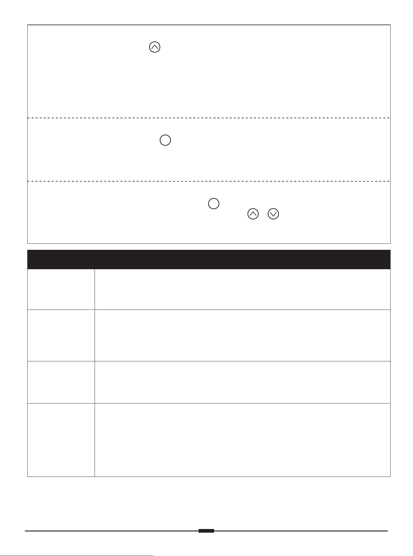
Electric Standing Desk Instruction Manual
ERDS4-01
Thank you for choosing ErgoAV!
At ErgoAV, our goal is to add value to your AV experience by providing the highest
quality products and services in the industry. We offer a 5-year warranty. If you have
any questions or concerns, please contact us.
(877) 419-7832 Mon-Fri 8am - 8pm (CST)
support@ergoav.com
www.ergoav.com
9501 Louisiana Ave N, #200, Brooklyn Park, MN 55445
ErgoAV
English 01-19 Español 39 a 57Français 20 à 38
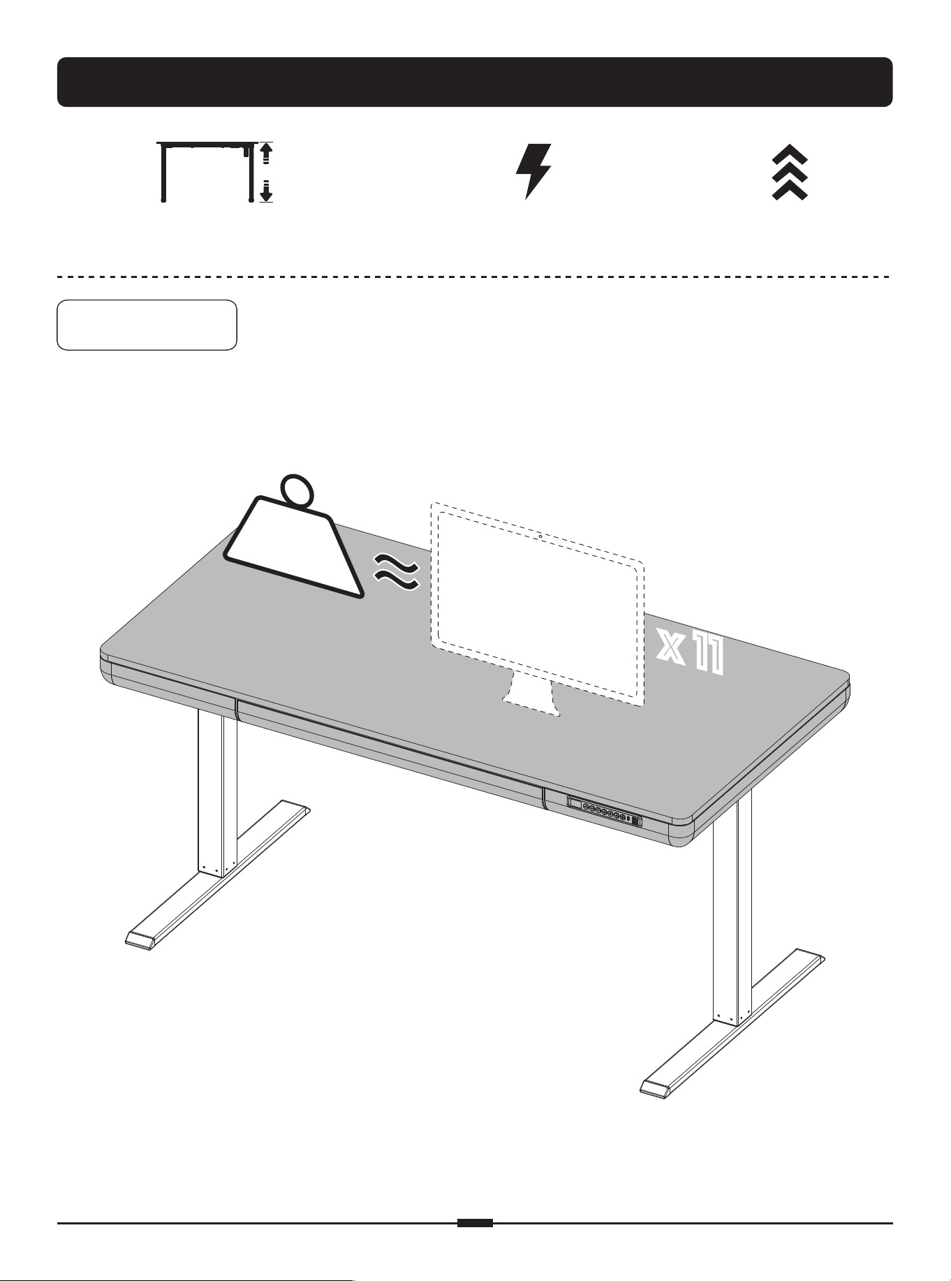
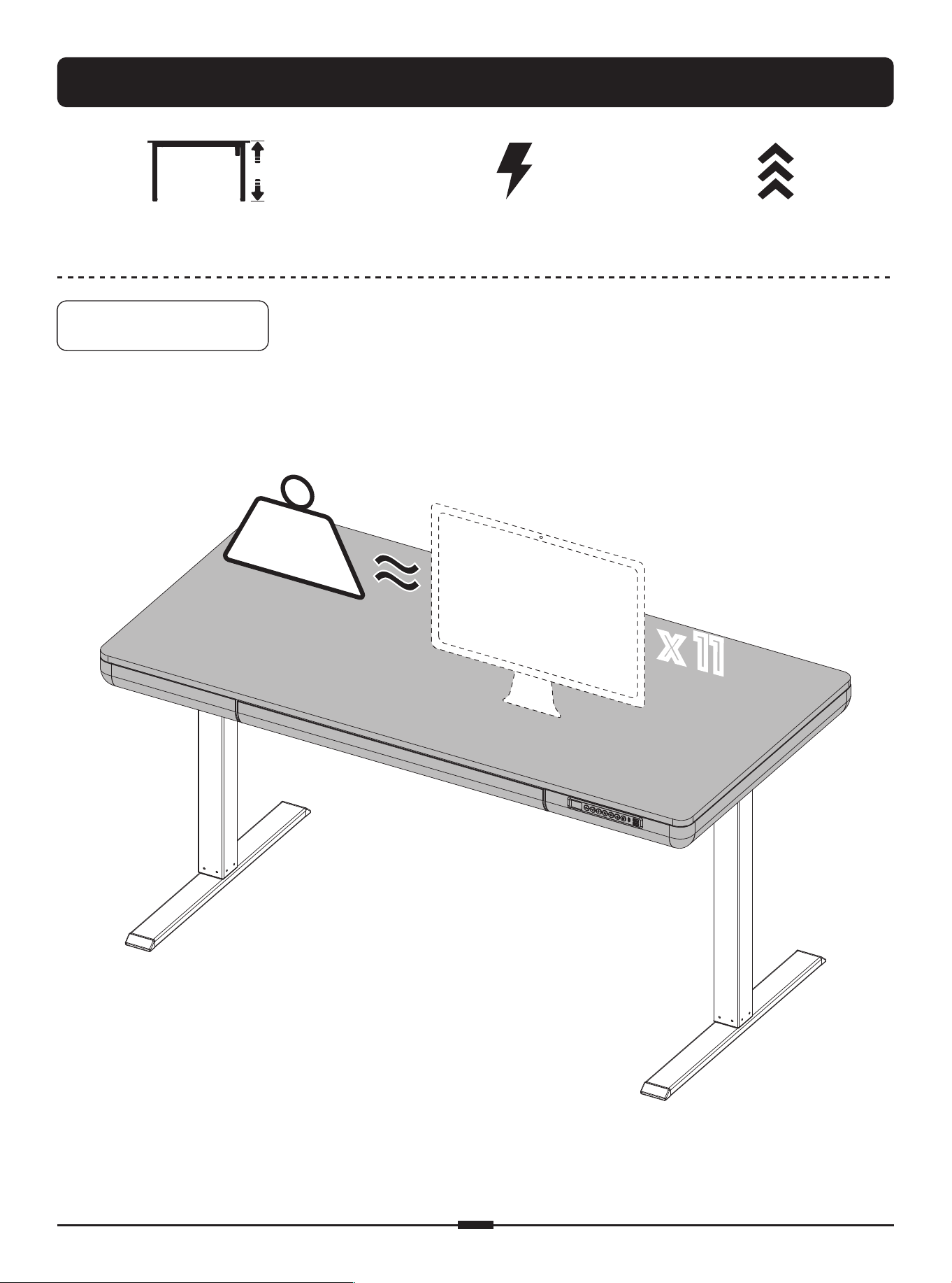
Specifications
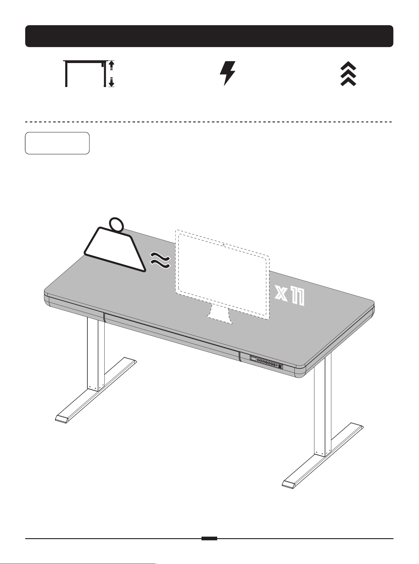
Max. Load
154 lbs / 70kg (Desktop + Other Items)
Power Input
100V-240V
Max. Speed
18mm/s
Height Adjustment Range
27.6–46.5” (70-118cm)
x 11x 11
Monitor weight:
14 lbs / 6.3kg
154 lbs
(70kg)
01 02 03 04 05 06 07 08 09 10
11 12 13 14 15 16 17 18 19
20 21 22 23 24 25 26 27 28 29
30 31 32 33 34 35 36 37 38
39 40 41 42 43 44 45 46 47 48
49 50 51 52 53 54 55 56 57
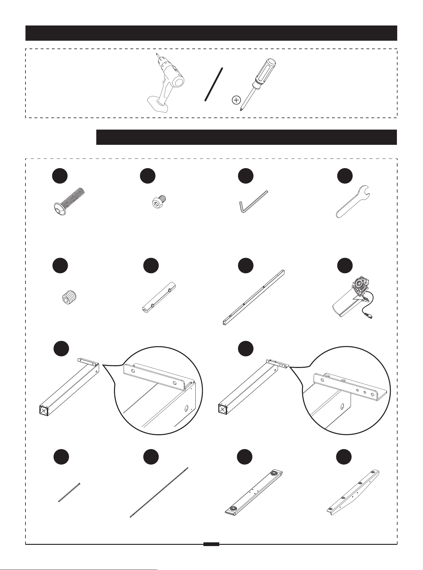
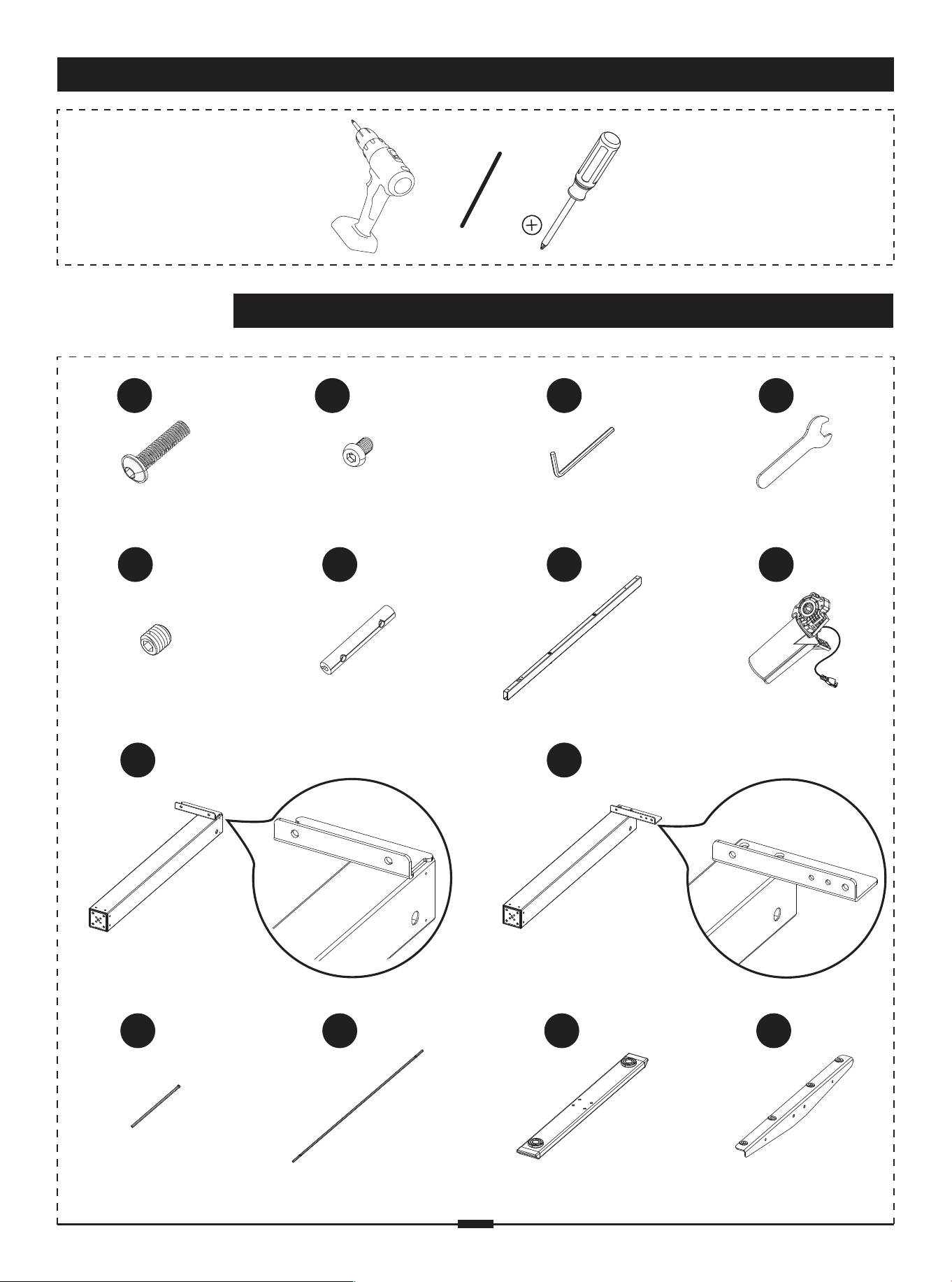
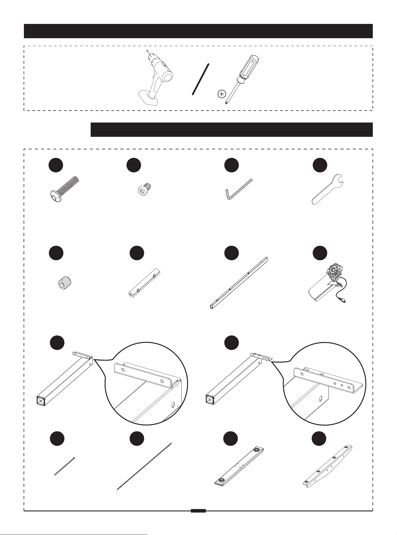
Crossbar
01
x 1
R Leg
04
x 1
L Leg
03
x 1
Leg Base
07
x 2
Step 1
Supplied Parts and Hardware
Tools Needed (Not Included)
Side Plate
08
x 2
A
x 8
Bolt
M6 x 30mm
B
x 10
Bolt
M6 x 10mm
Transmission Rod
06
x 1
Rod Coupler
K2
x 1
Transmission Rod
05
x 1
Wrench
I
x 1
C
x 1
Motor
02
x 1
K1
x 2
Set Screw
Allen Key
5/32” (4mm)
01 02 03 04 05 06 07 08 09 10
11 12 13 14 15 16 17 18 19
20 21 22 23 24 25 26 27 28 29
30 31 32 33 34 35 36 37 38
39 40 41 42 43 44 45 46 47 48
49 50 51 52 53 54 55 56 57
Step 2
Supplied Parts and Hardware
Step 3
Supplied Parts and Hardware
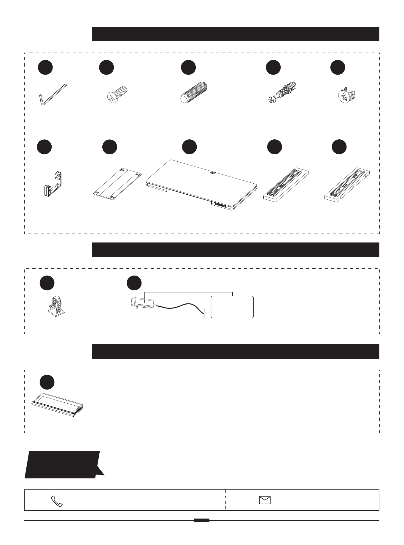
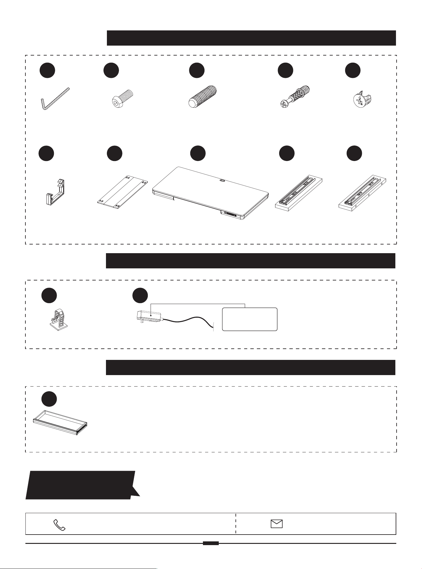
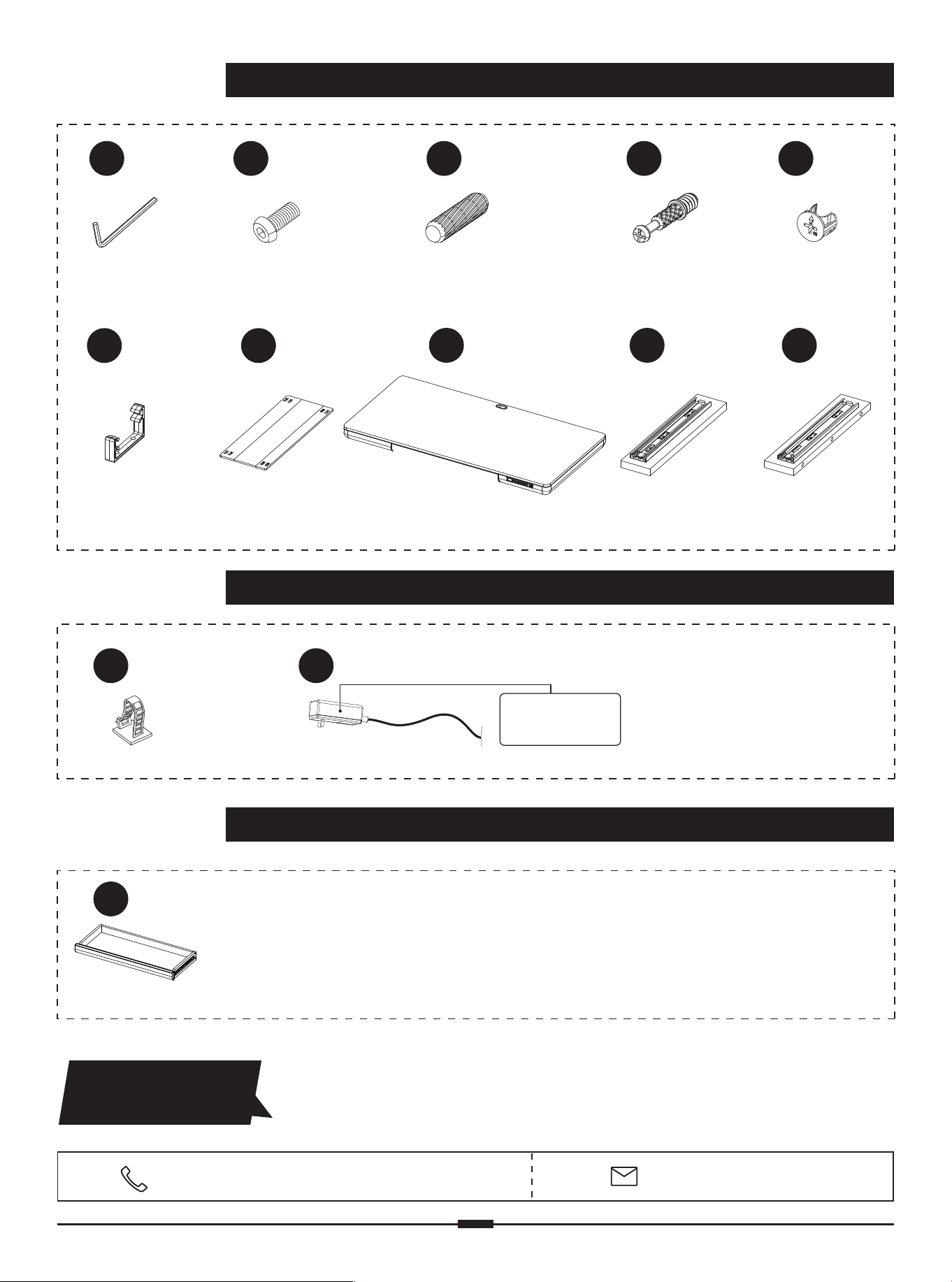
Cable Clip
H
x 4
14
x 1
Power Cable
If you receive parts that are damaged, defective, or are
missing parts, please contact us.
Contact Us
(877) 419-7832 Mon-Fri 8am - 8pm (CST)
support@ergoav.com
Not all hardware included in this package will be used.
Actual part
may vary.
Step 4
Supplied Parts and Hardware
15
x 1
Drawer
Tray Bracket
09
x 2
10
x 1
11
x 1
Cable
Management Tray
Desktop
C
x 1
Allen Key
5/32” (4mm)
Bolt
M6 x 14mm
D
x 14
12
x 1
Drawer
Support Panel
13
x 1
Drawer
Support Panel
Cam Lock
L2
x 4
Cam Bolt
L1
x 4
Wood Dowel
G
x 2
01 02 03 04 05 06 07 08 09 10
11 12 13 14 15 16 17 18 19
20 21 22 23 24 25 26 27 28 29
30 31 32 33 34 35 36 37 38
39 40 41 42 43 44 45 46 47 48
49 50 51 52 53 54 55 56 57
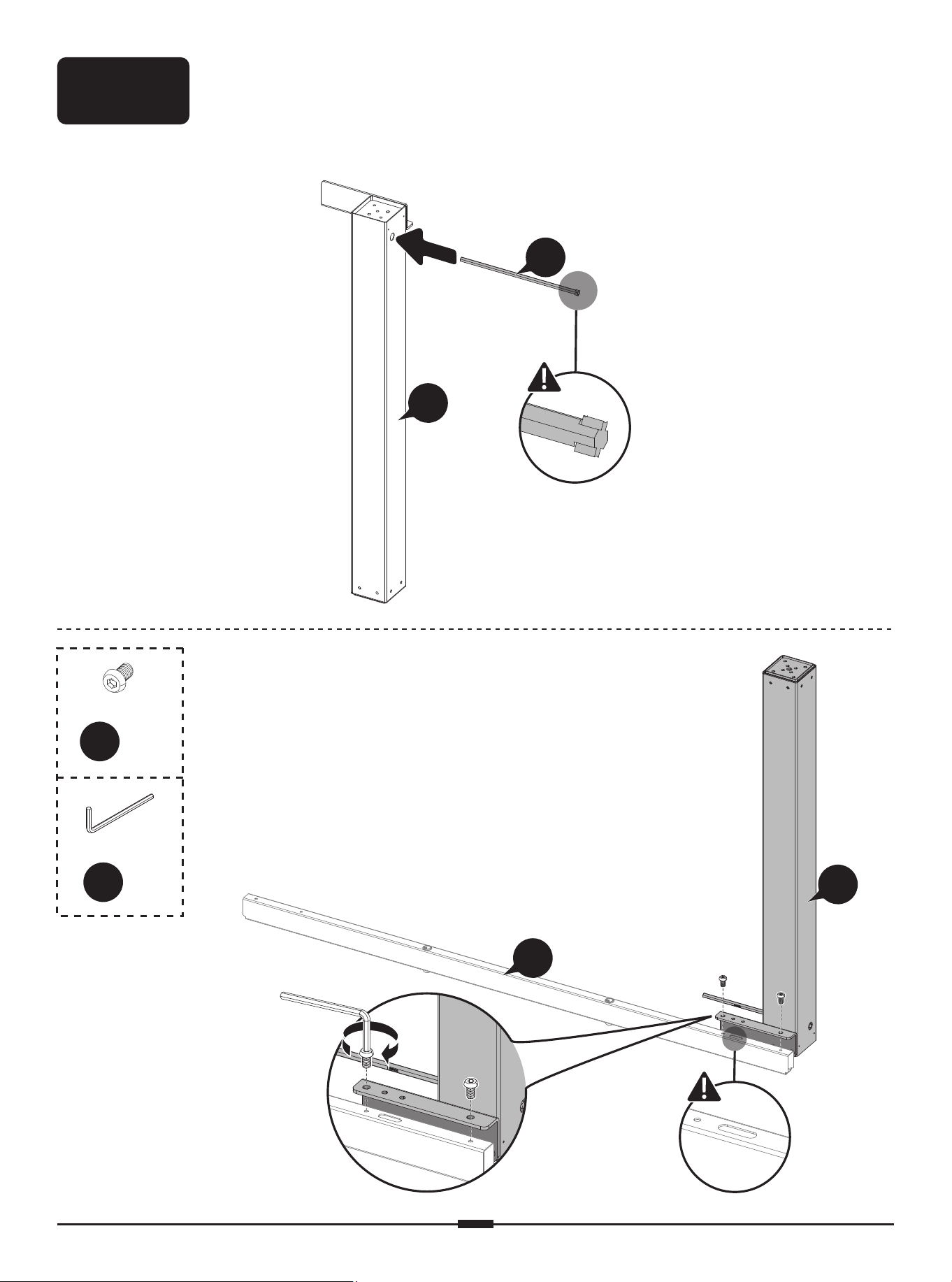
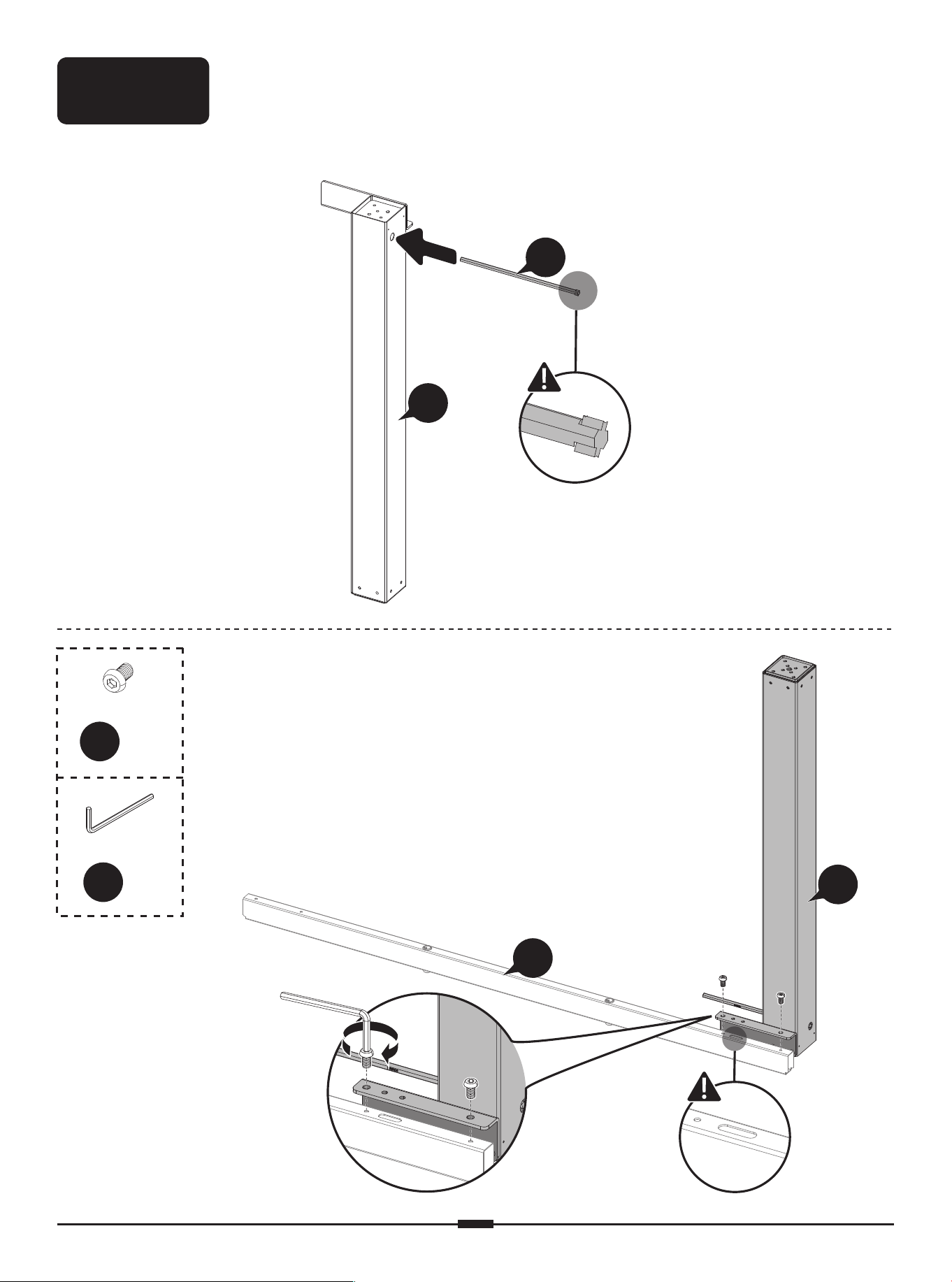
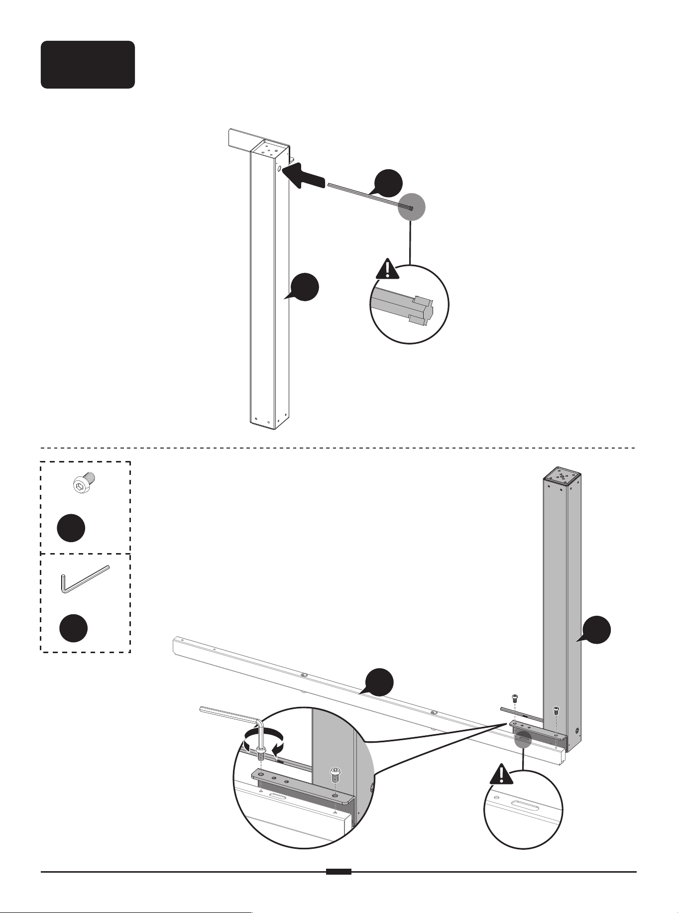
Step 1
Assembling the Frame
05
04
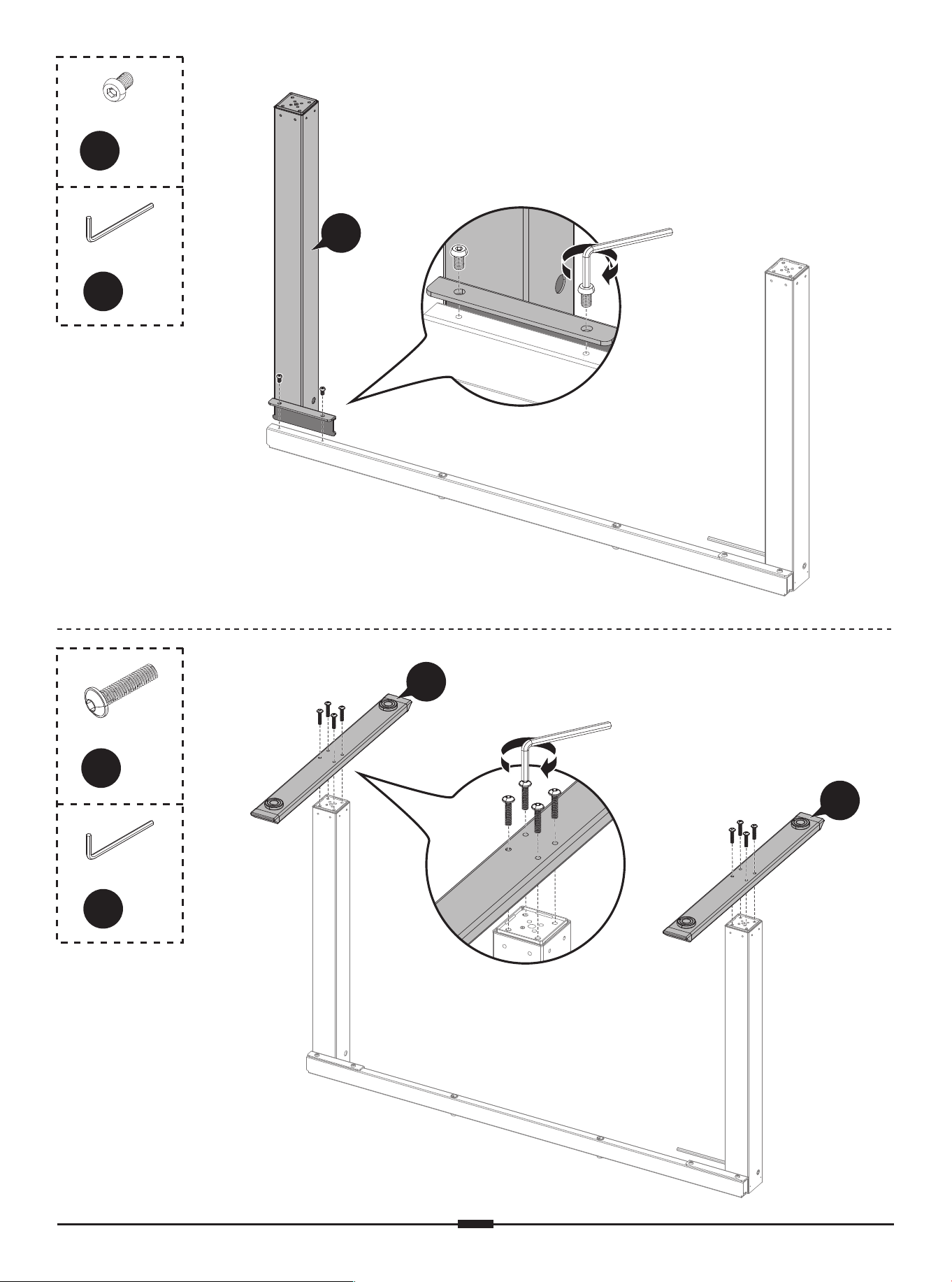
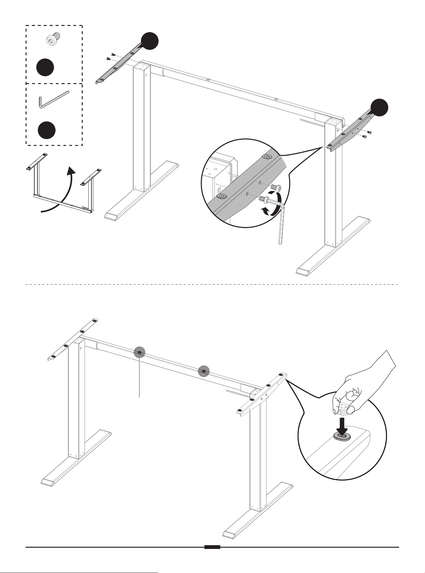
Connect the short transmission rod to the R leg.
B
x 2
M6 x 10mm
5/32” (4mm)
C
x 1
01
04
01 02 03 04 05 06 07 08 09 10
11 12 13 14 15 16 17 18 19
20 21 22 23 24 25 26 27 28 29
30 31 32 33 34 35 36 37 38
39 40 41 42 43 44 45 46 47 48
49 50 51 52 53 54 55 56 57
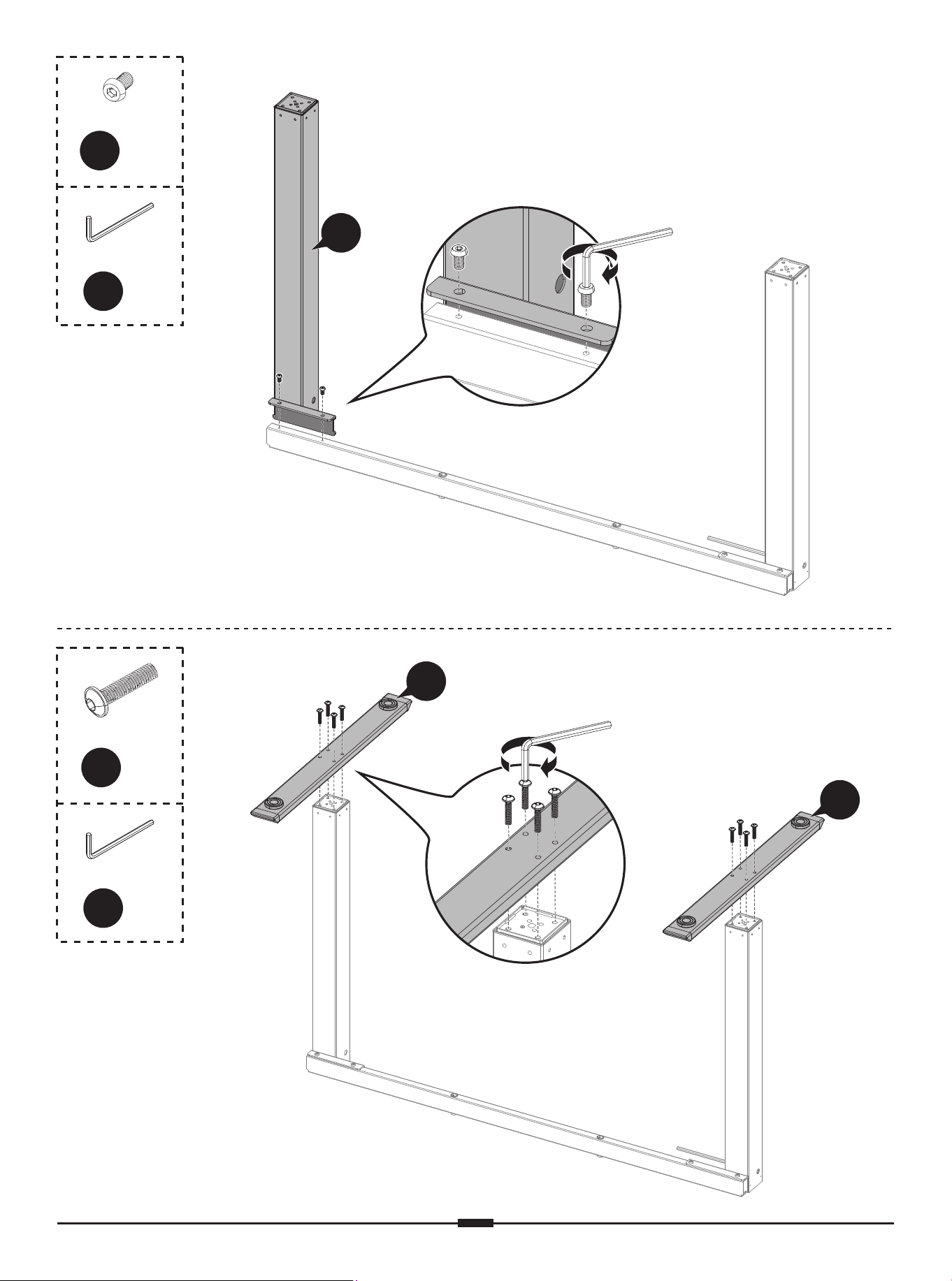
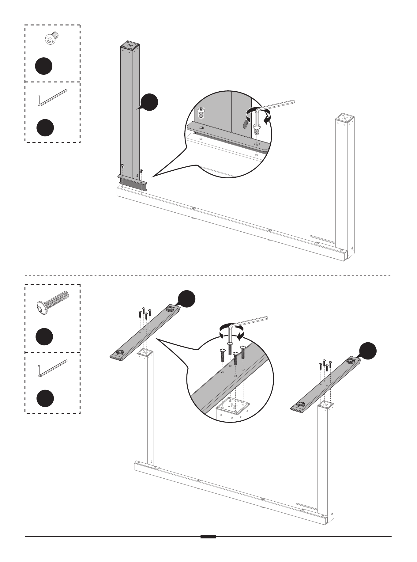
B
x 2
M6 x 10mm
5/32” (4mm)
C
x 1
03
5/32” (4mm)
C
x 1
A
x 8
M6 x 30mm
07
07
01 02 03 04 05 06 07 08 09 10
11 12 13 14 15 16 17 18 19
20 21 22 23 24 25 26 27 28 29
30 31 32 33 34 35 36 37 38
39 40 41 42 43 44 45 46 47 48
49 50 51 52 53 54 55 56 57
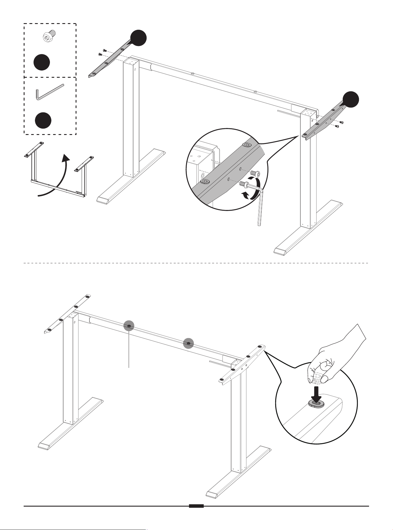
B
x 4
M6 x 10mm
5/32” (4mm)
C
x 1
08
08
180°
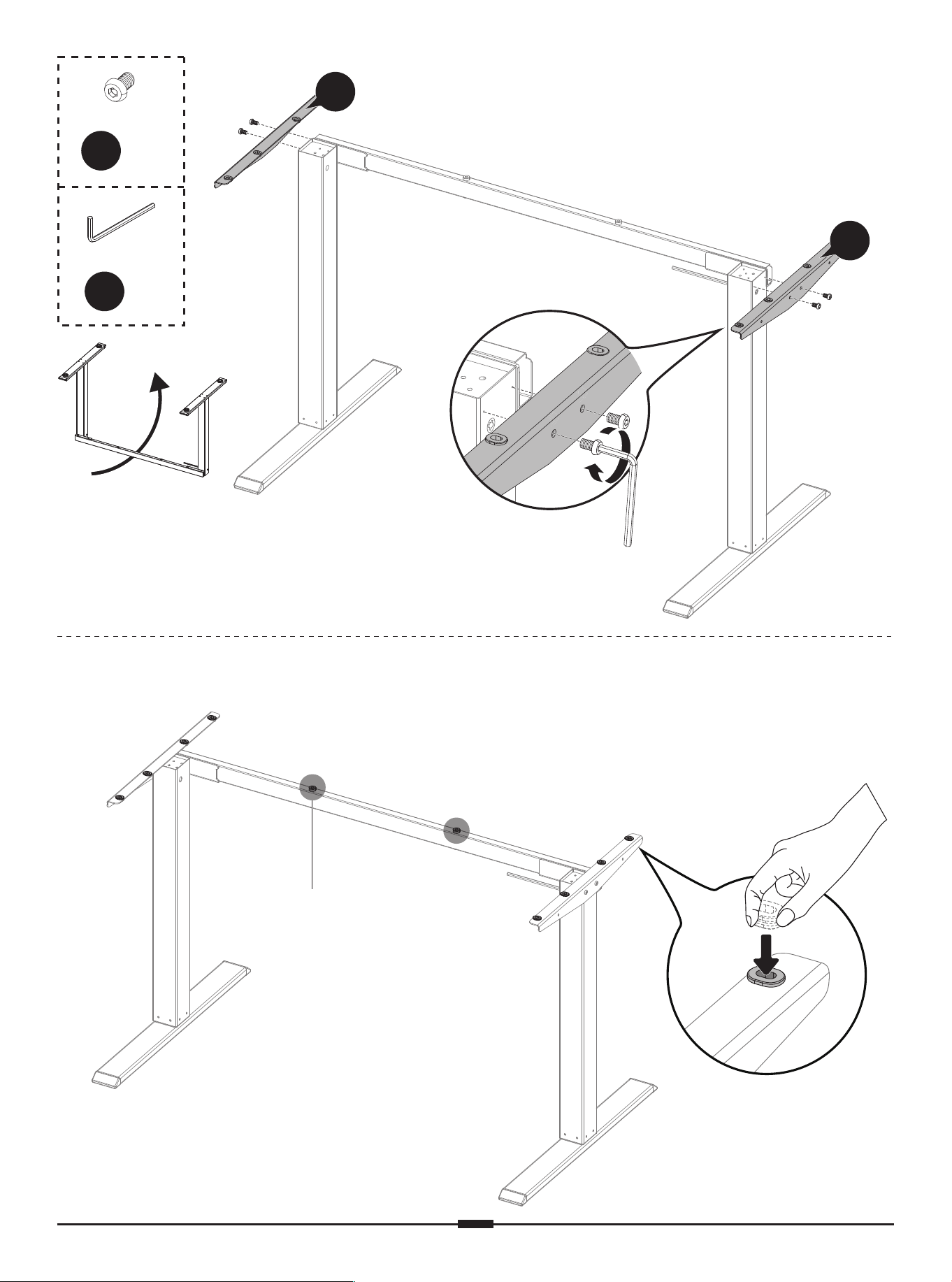
Ensure the rubber pads are attached to the frame. If any have fallen off, reattach them
or use the spare rubber pads.
Tall Rubber Pads
01 02 03 04 05 06 07 08 09 10
11 12 13 14 15 16 17 18 19
20 21 22 23 24 25 26 27 28 29
30 31 32 33 34 35 36 37 38
39 40 41 42 43 44 45 46 47 48
49 50 51 52 53 54 55 56 57
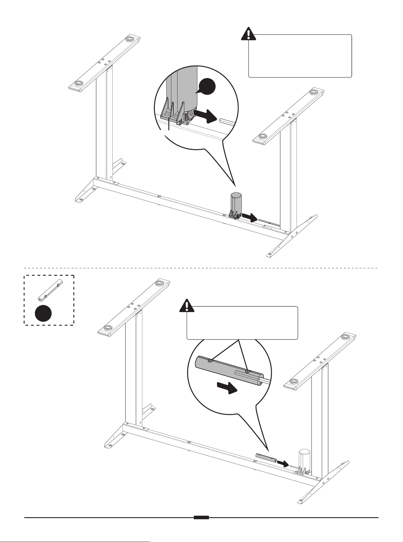
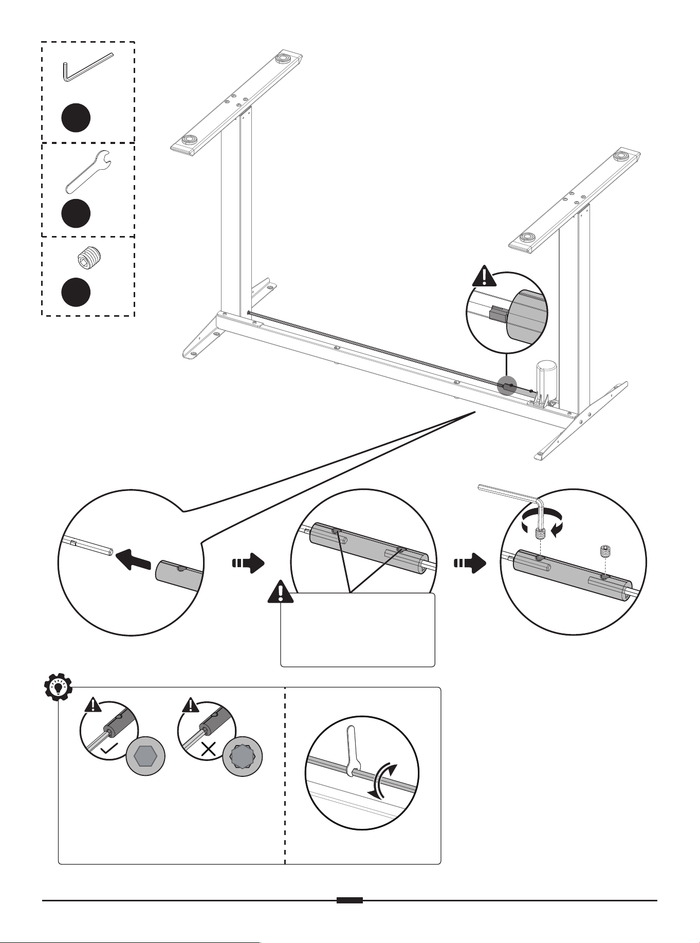
K2
x 1
TabTab
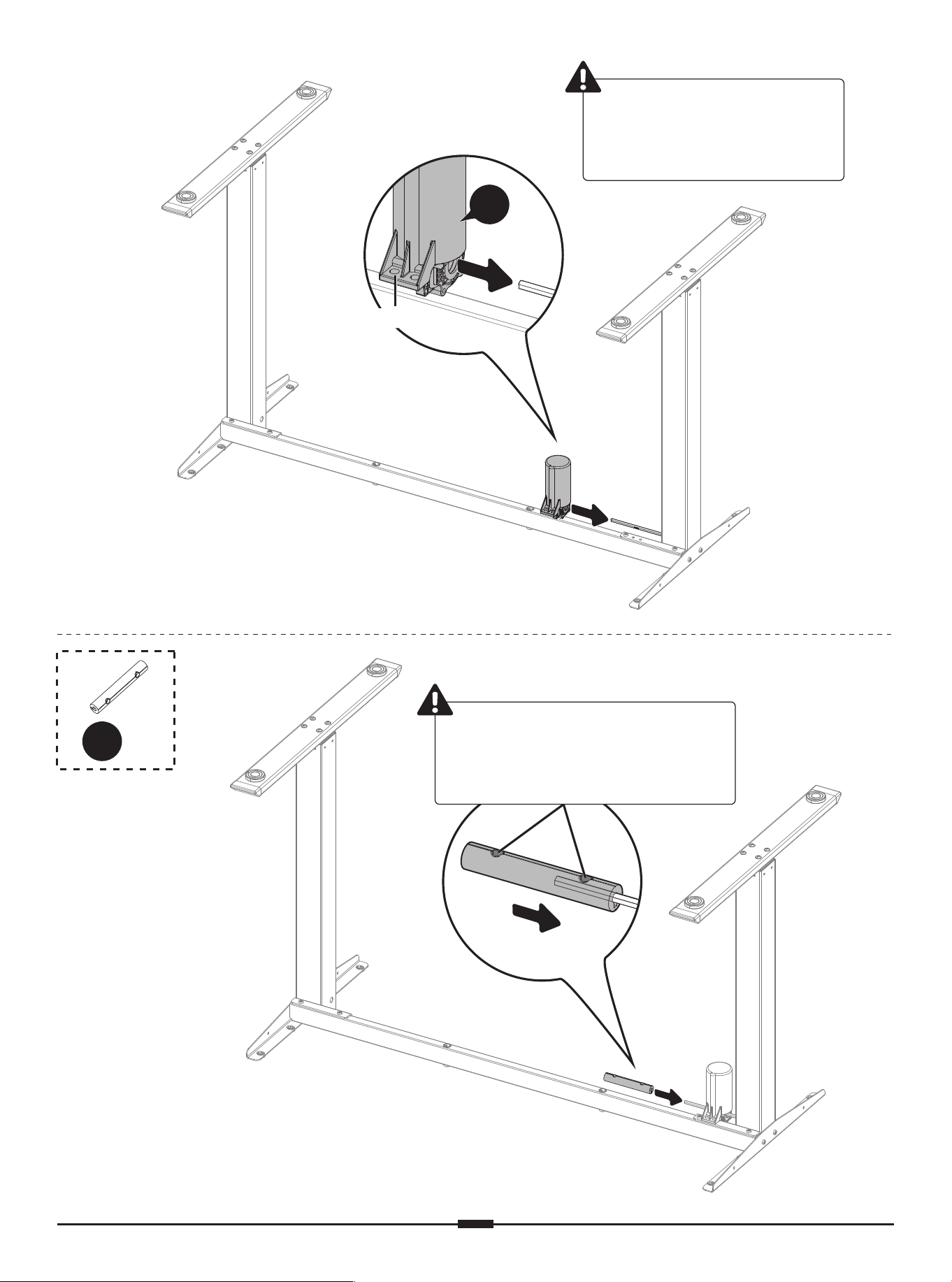
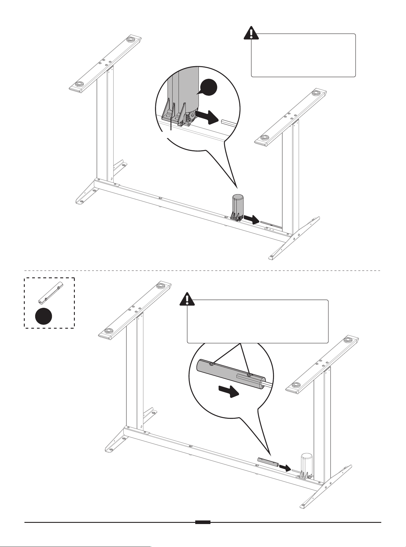
Make sure the holes for
set screws face up.
Insert the motor into
the transmission rod
but do not secure it.
02
01 02 03 04 05 06 07 08 09 10
11 12 13 14 15 16 17 18 19
20 21 22 23 24 25 26 27 28 29
30 31 32 33 34 35 36 37 38
39 40 41 42 43 44 45 46 47 48
49 50 51 52 53 54 55 56 57
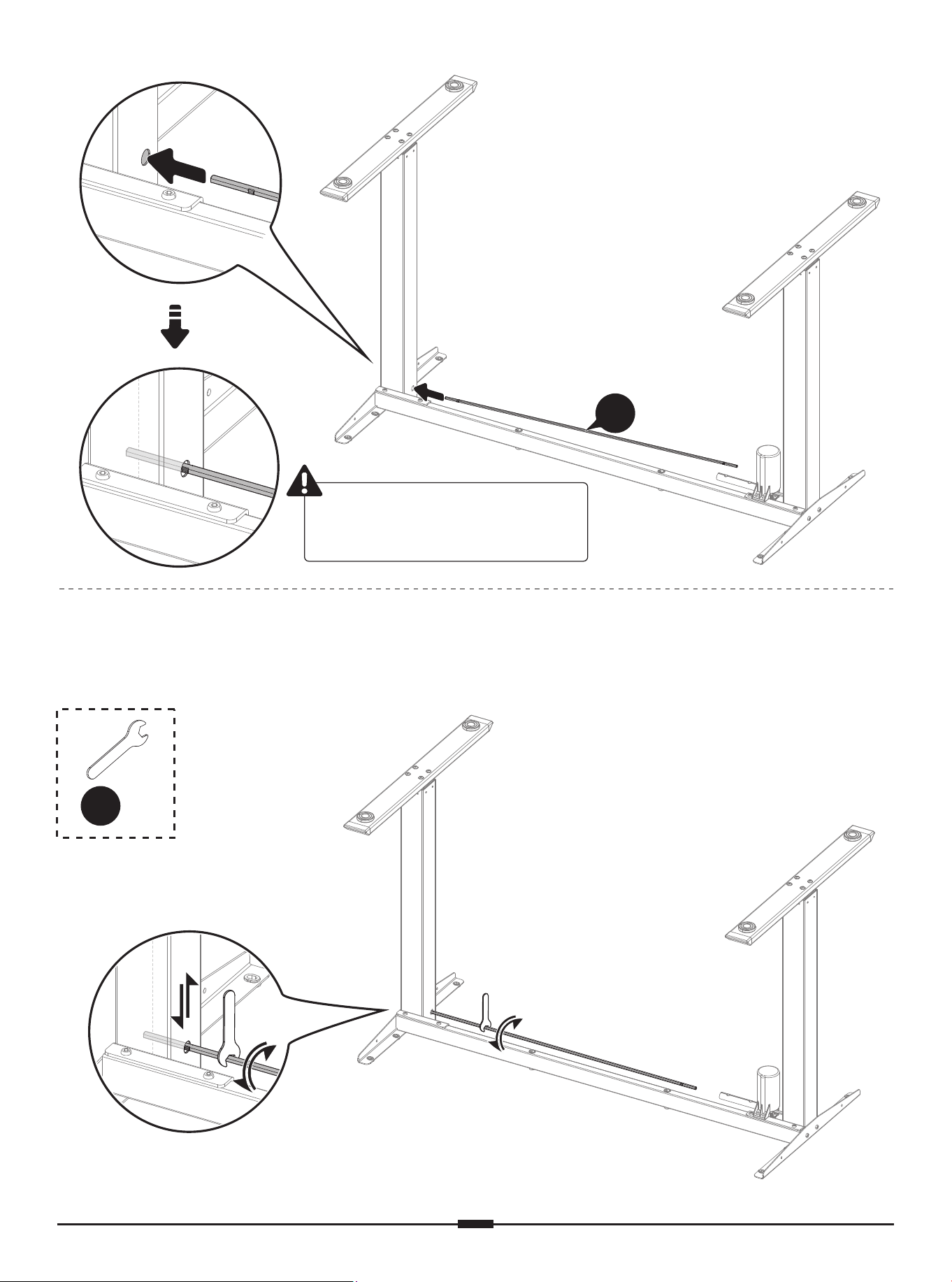
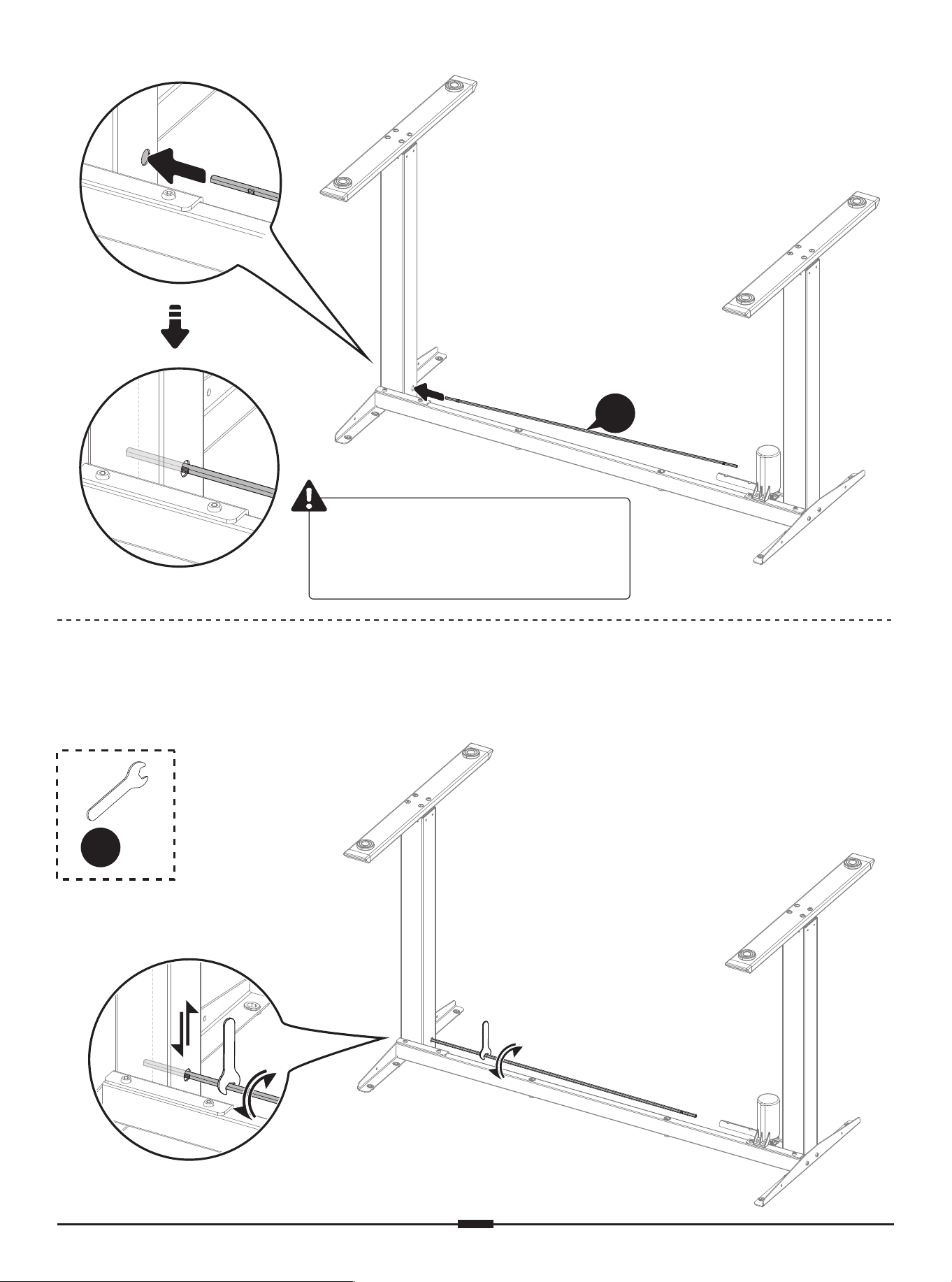
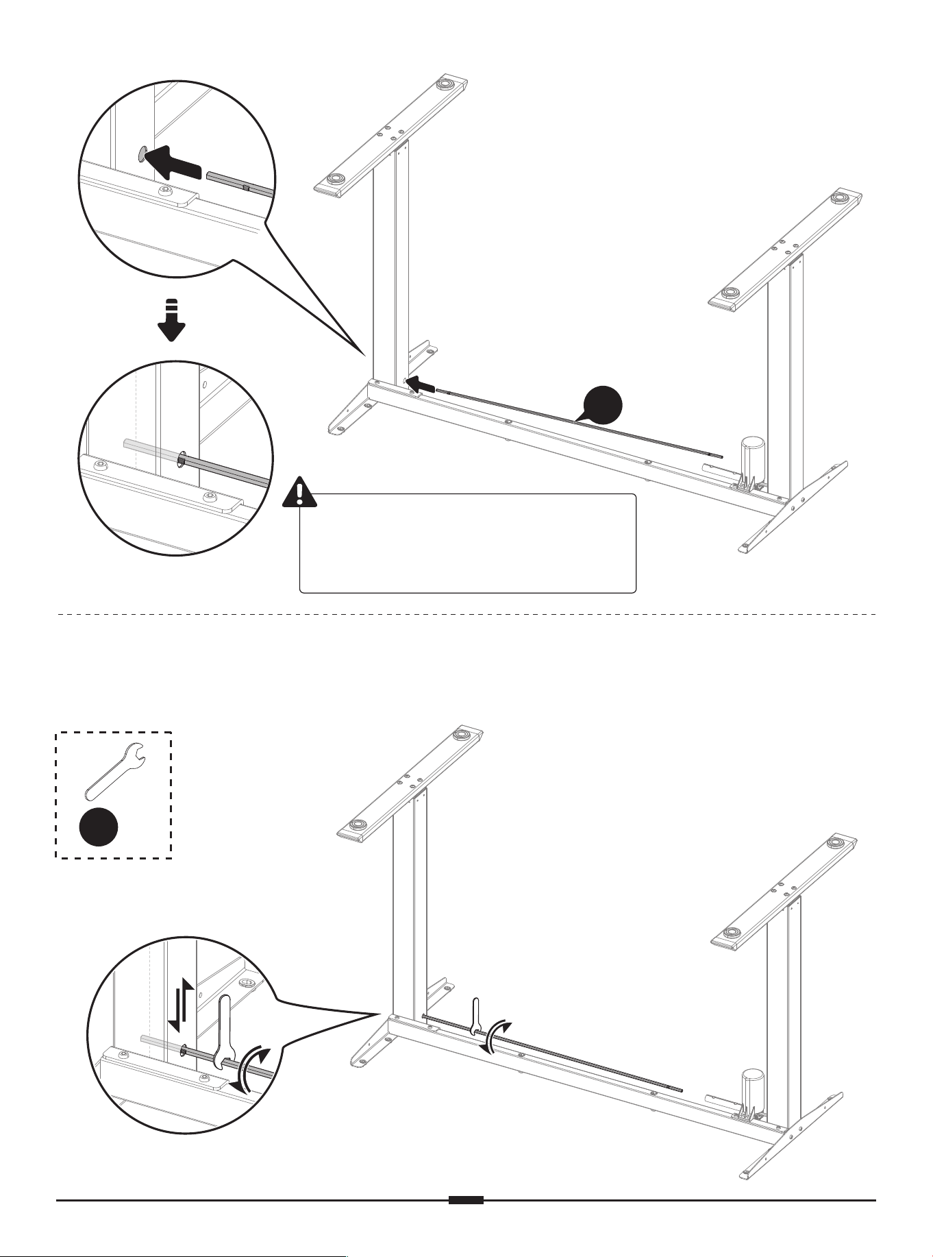
Measure the height of each leg to see if they are set at the same level. If not, turn the rod
to raise or lower the leg until it's level with the leg with motor.
Adjust uneven desk legs if needed:
I
x 1
06
Ensure the rod end is fully
inserted into the leg.
01 02 03 04 05 06 07 08 09 10
11 12 13 14 15 16 17 18 19
20 21 22 23 24 25 26 27 28 29
30 31 32 33 34 35 36 37 38
39 40 41 42 43 44 45 46 47 48
49 50 51 52 53 54 55 56 57
K1
x 2
I
x 1
5/32” (4mm)
C
x 1
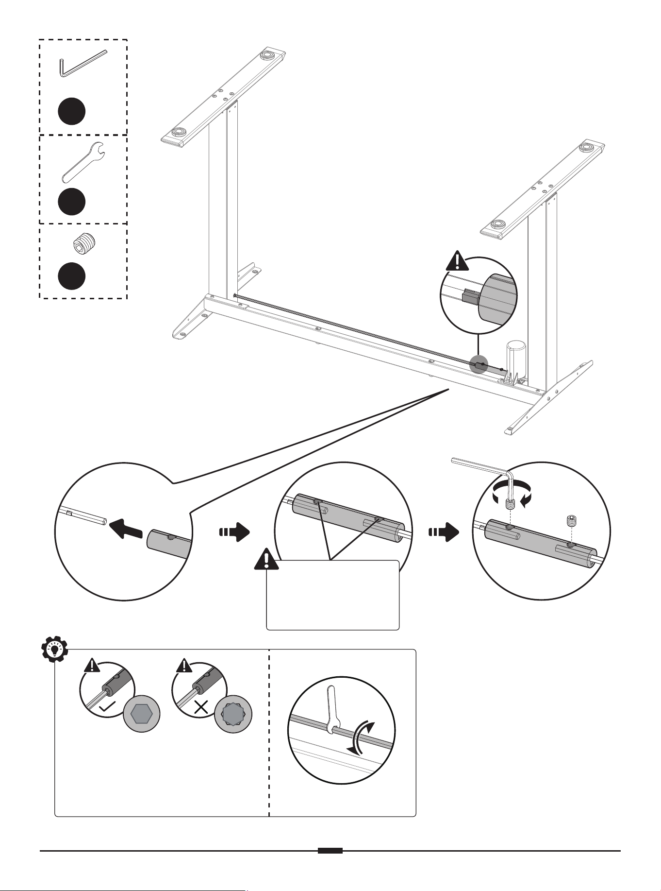
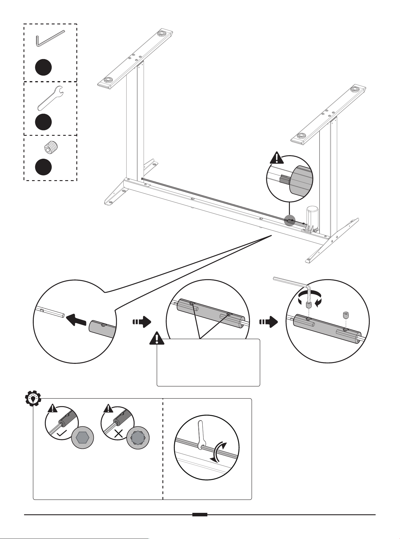
If the transmission rod
does not fit smoothly,
use the wrench to
fine-tune the position.
Ensure the rods
are under these
screw holes.
01 02 03 04 05 06 07 08 09 10
11 12 13 14 15 16 17 18 19
20 21 22 23 24 25 26 27 28 29
30 31 32 33 34 35 36 37 38
39 40 41 42 43 44 45 46 47 48
49 50 51 52 53 54 55 56 57
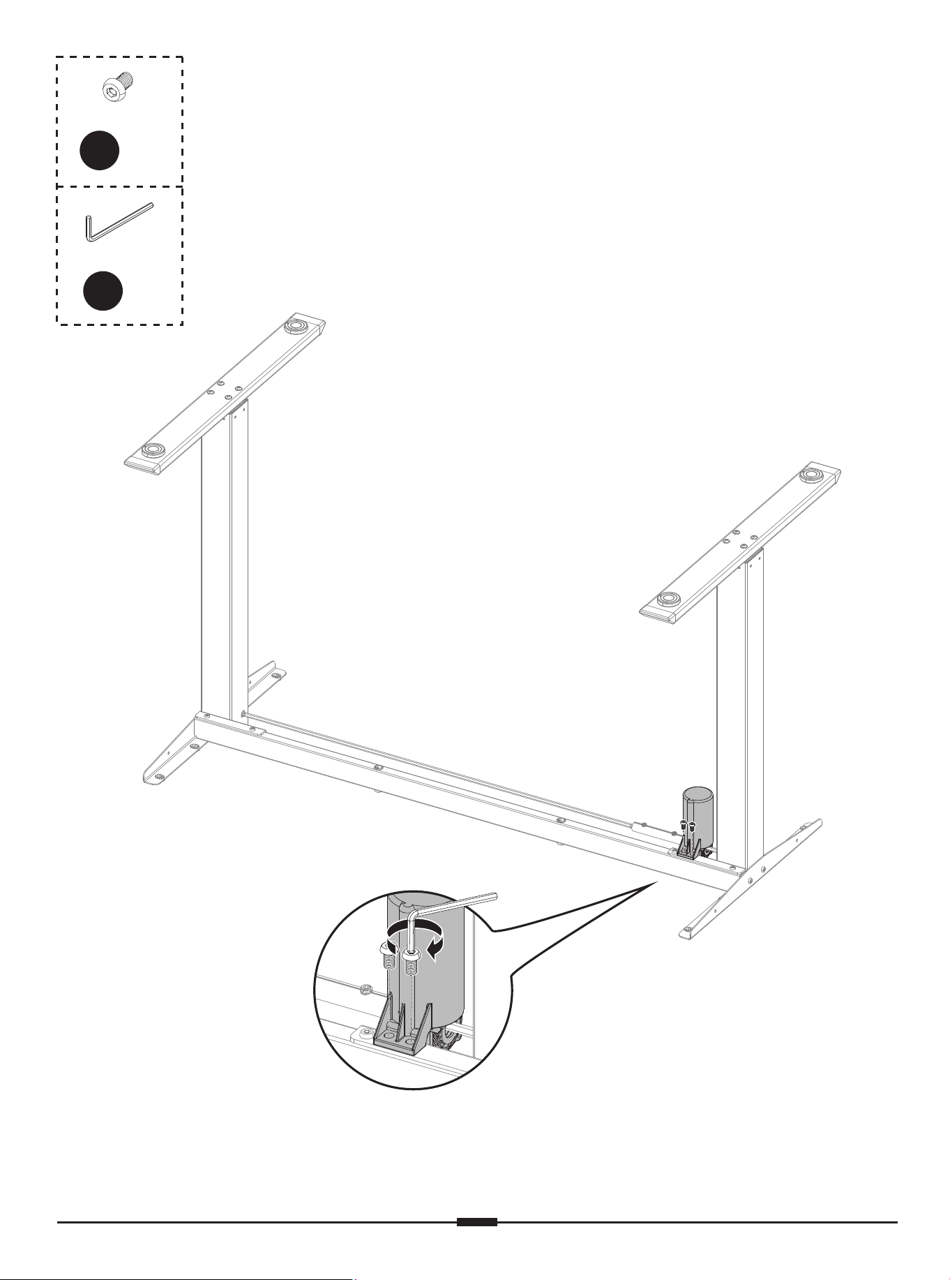
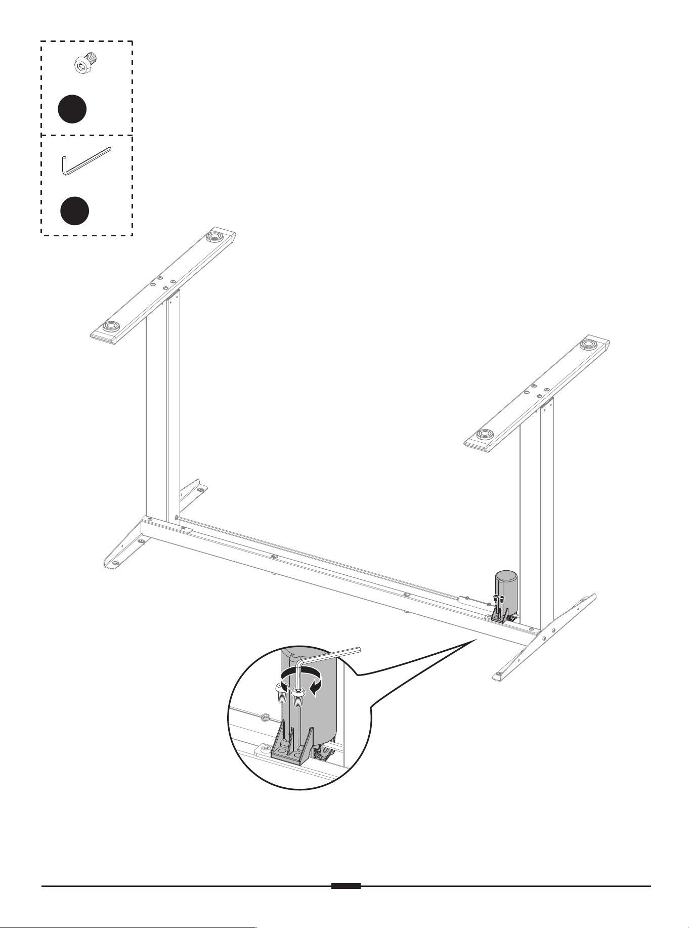
B
x 2
M6 x 10mm
5/32” (4mm)
C
x 1
01 02 03 04 05 06 07 08 09 10
11 12 13 14 15 16 17 18 19
20 21 22 23 24 25 26 27 28 29
30 31 32 33 34 35 36 37 38
39 40 41 42 43 44 45 46 47 48
49 50 51 52 53 54 55 56 57
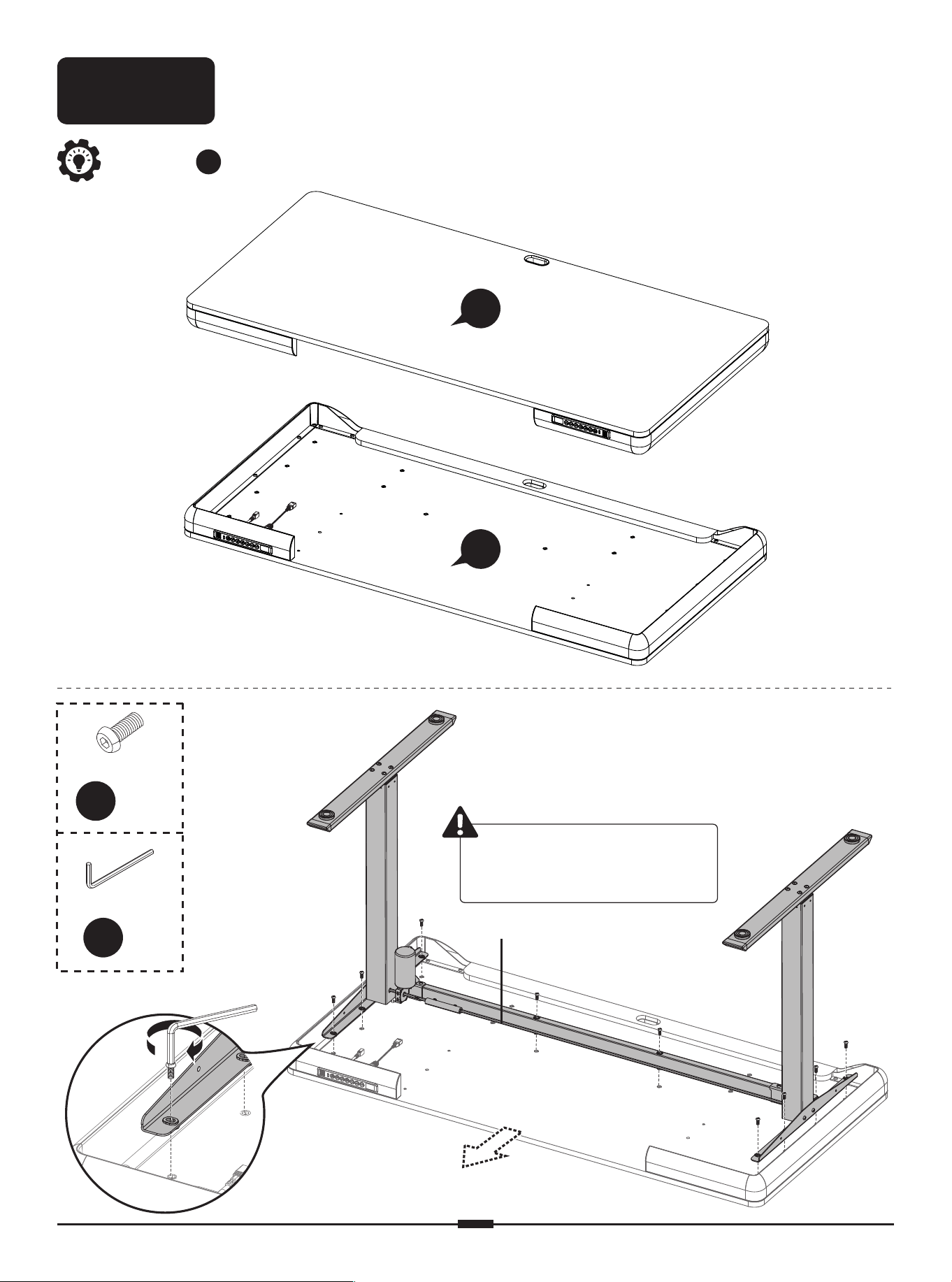
TopTop
BottomBottom
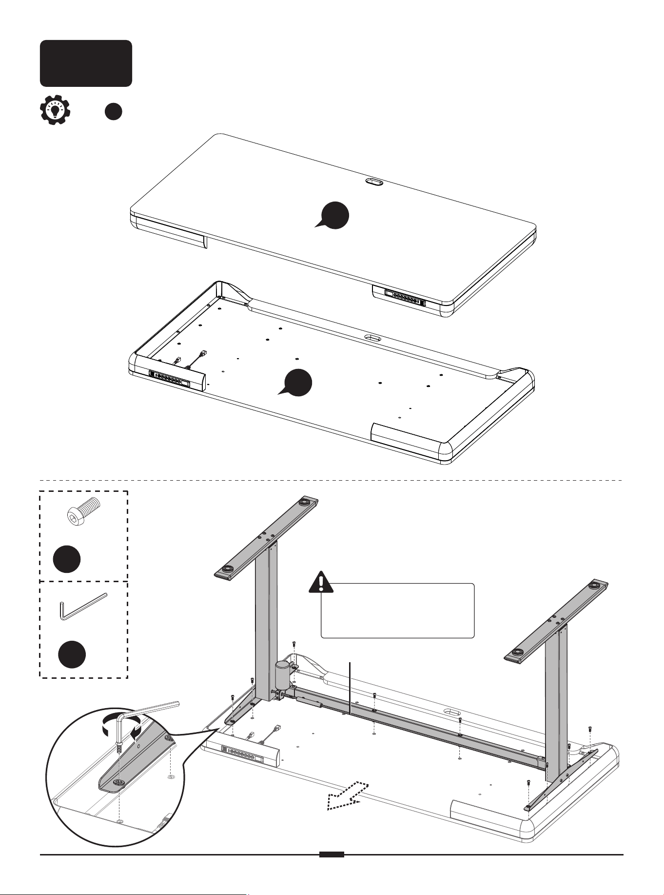
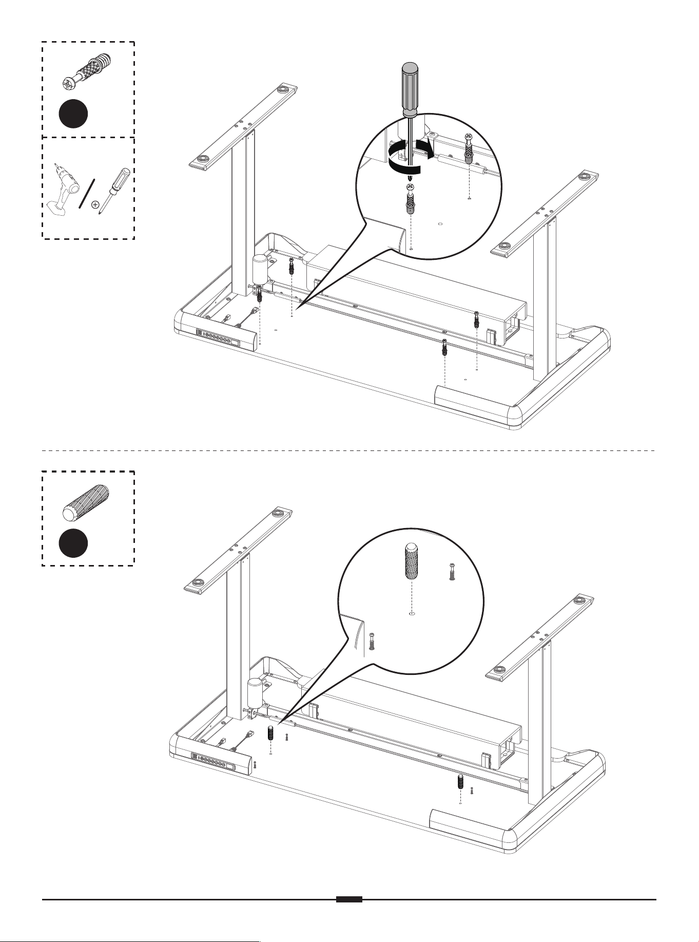
Tip: indicate pre-drilled hole locations.
11
11
Step 2
Attaching the Desktop and Other Parts
The transmission
rod faces the front.
FrontFront
Transmission RodTransmission Rod
D
x 10
M6 x 14mm
5/32” (4mm)
C
x 1
01 02 03 04 05 06 07 08 09 10
11 12 13 14 15 16 17 18 19
20 21 22 23 24 25 26 27 28 29
30 31 32 33 34 35 36 37 38
39 40 41 42 43 44 45 46 47 48
49 50 51 52 53 54 55 56 57
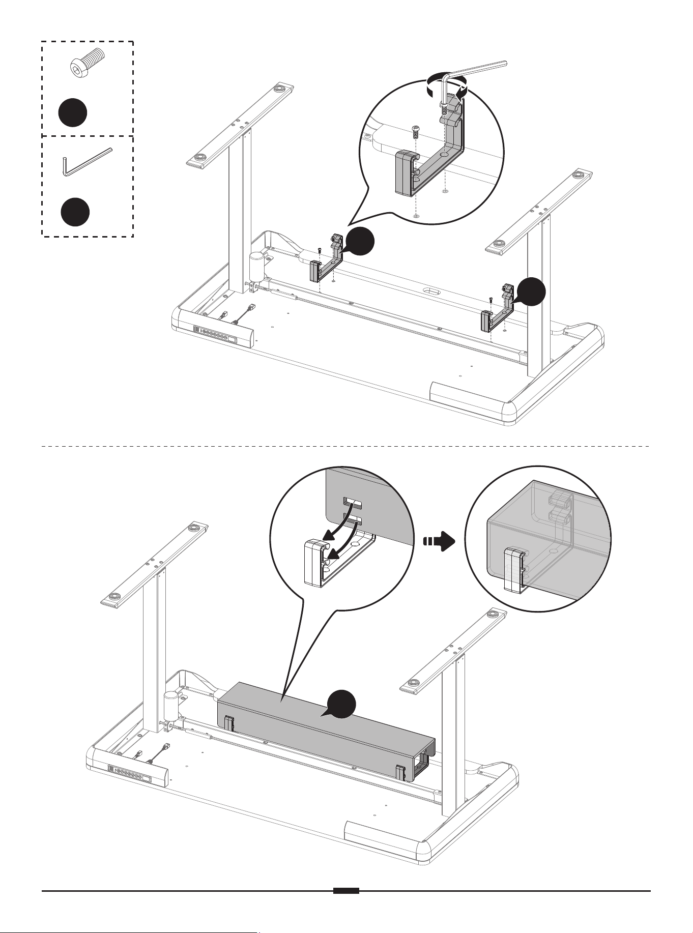
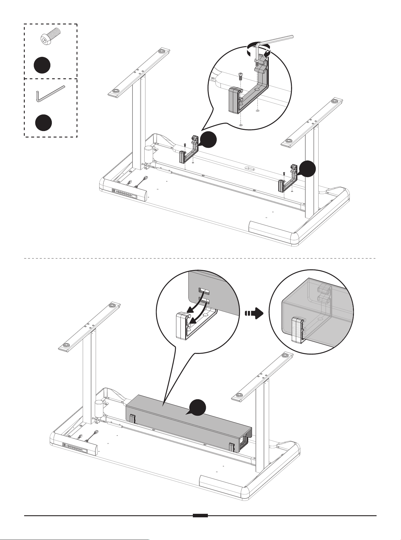
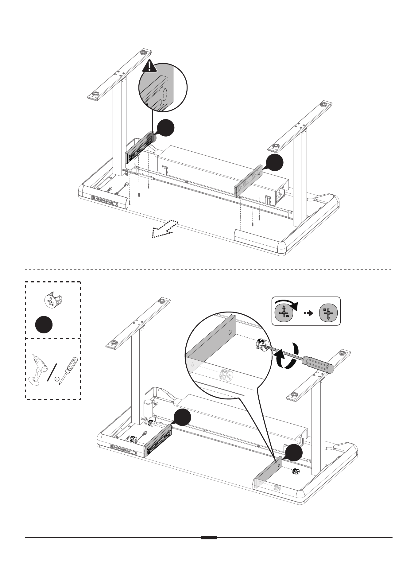
09
09
D
x 4
M6 x 14mm
5/32” (4mm)
C
x 1
10
01 02 03 04 05 06 07 08 09 10
11
12 13 14 15 16 17 18 19
20 21 22 23 24 25 26 27 28 29
30 31 32 33 34 35 36 37 38
39 40 41 42 43 44 45 46 47 48
49 50 51 52 53 54 55 56 57
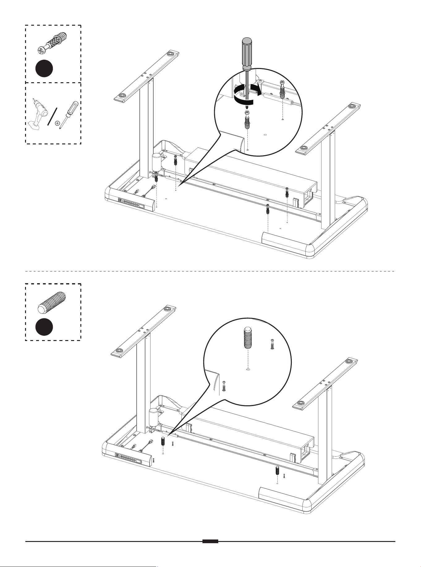
L1
x 4
G
x 2
01 02 03 04 05 06 07 08 09 10
11 12
13 14 15 16 17 18 19
20 21 22 23 24 25 26 27 28 29
30 31 32 33 34 35 36 37 38
39 40 41 42 43 44 45 46 47 48
49 50 51 52 53 54 55 56 57
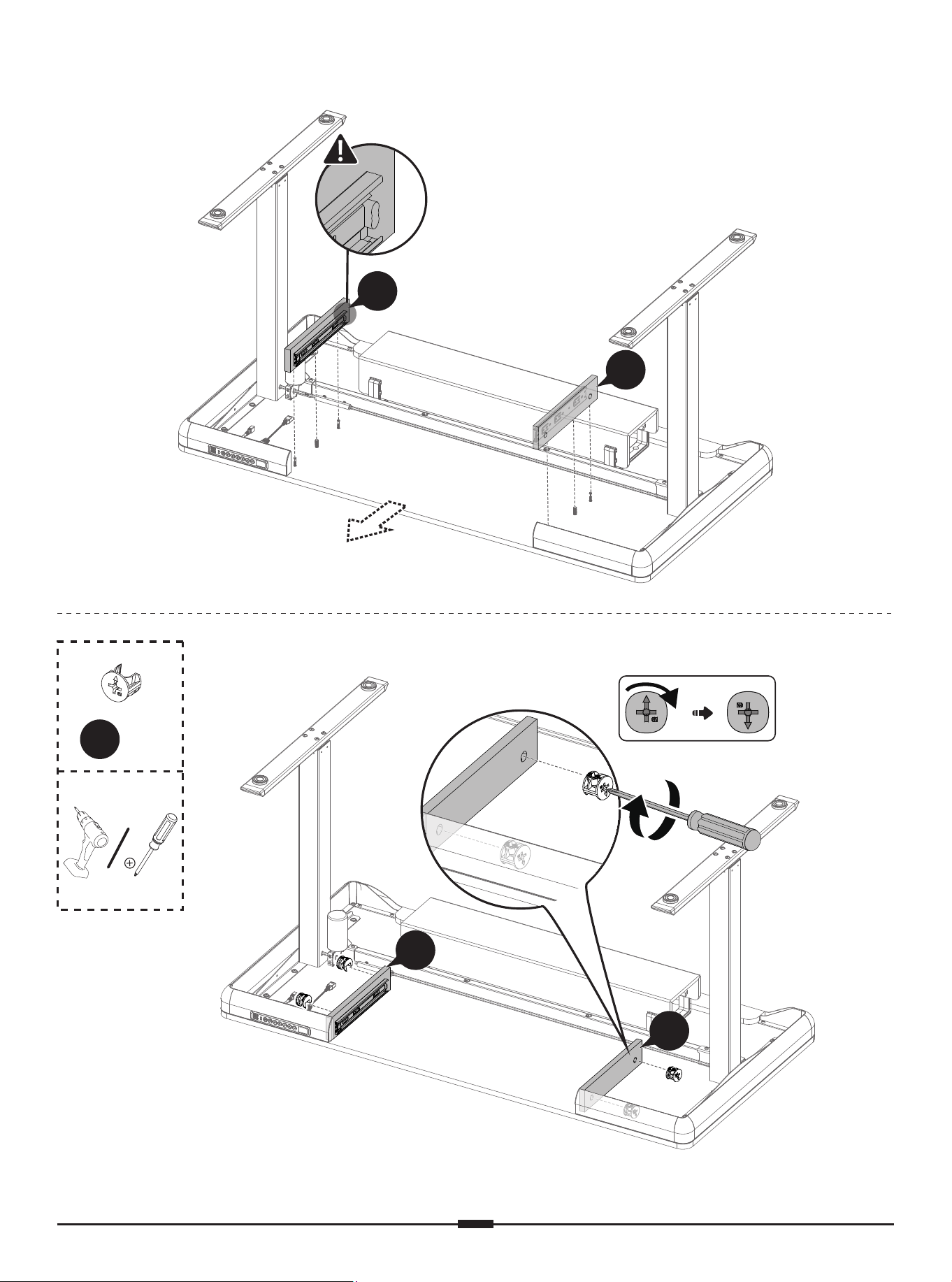
L2
x 4
180°
FrontFront
13
12
13
12
01 02 03 04 05 06 07 08 09 10
11 12 13
14 15 16 17 18 19
20 21 22 23 24 25 26 27 28 29
30 31 32 33 34 35 36 37 38
39 40 41 42 43 44 45 46 47 48
49 50 51 52 53 54 55 56 57
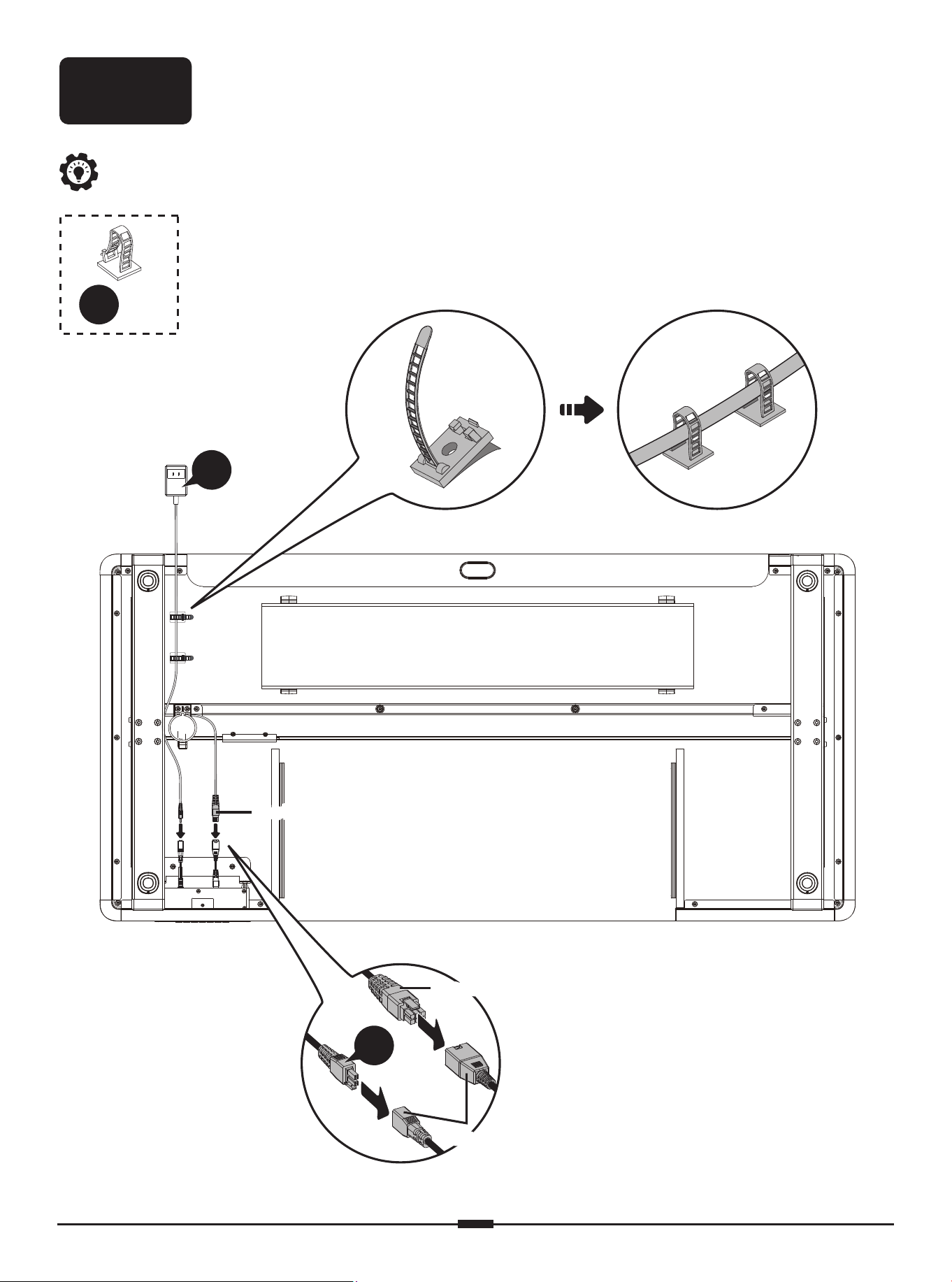
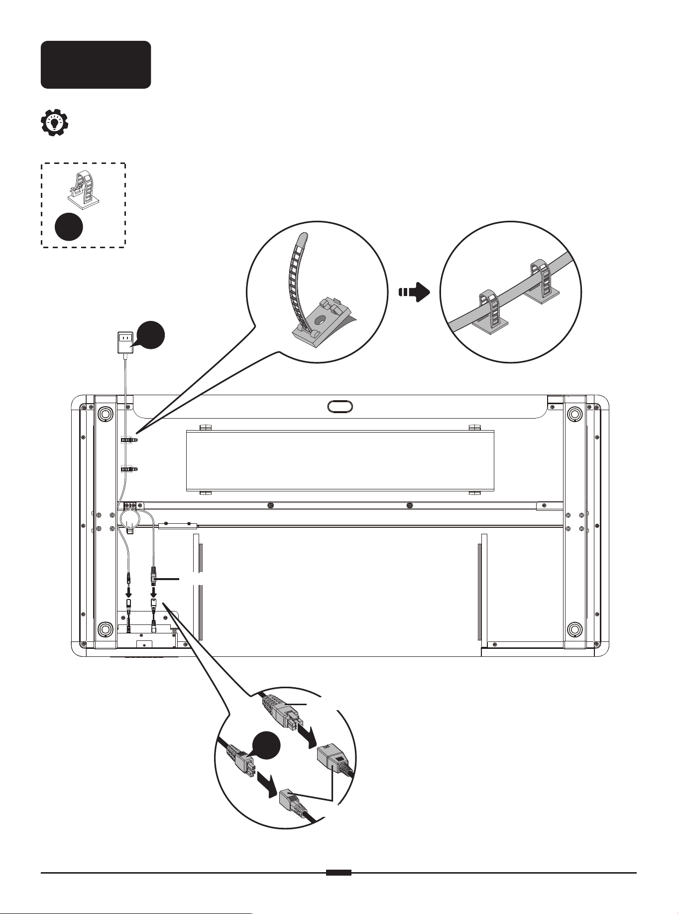
An example of a cable clip layout is indicated below. However, the cable clips can
be arranged according to your needs.
H
x 4
Step 3
Connecting the Cables
Motor CableMotor Cable
Motor CableMotor Cable
Controller CableController Cable
14
14
01 02 03 04 05 06 07 08 09 10
11 12 13 14
15 16 17 18 19
20 21 22 23 24 25 26 27 28 29
30 31 32 33 34 35 36 37 38
39 40 41 42 43 44 45 46 47 48
49 50 51 52 53 54 55 56 57
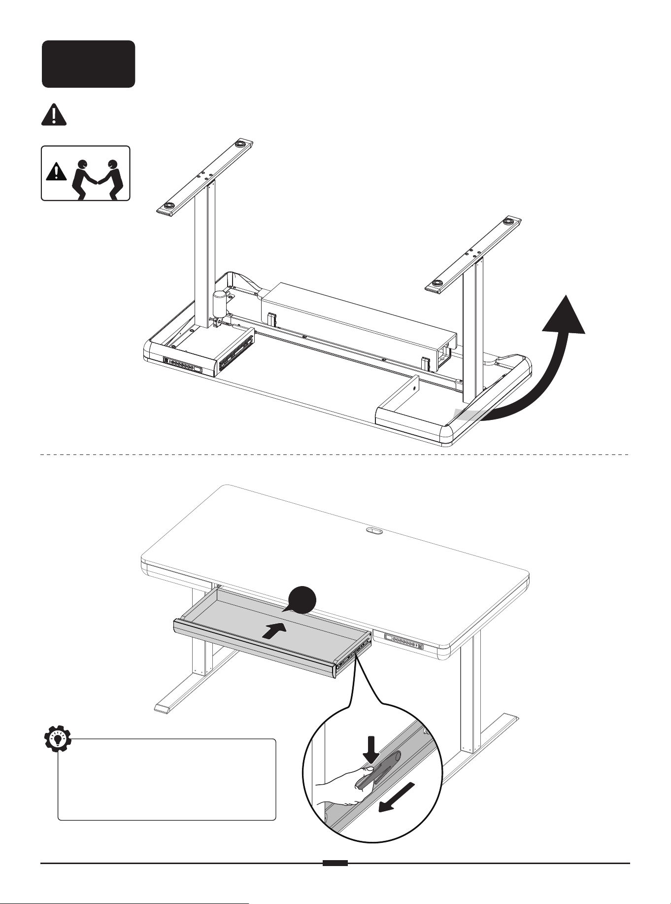
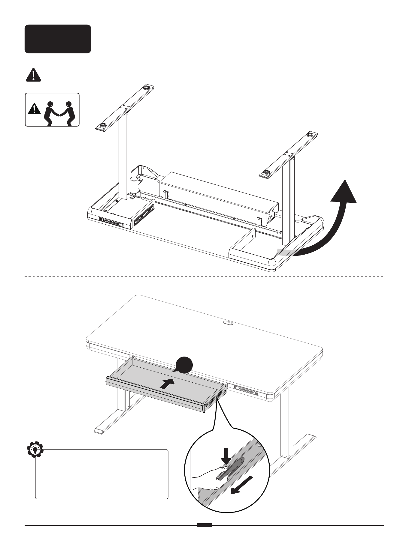
Step 4
Attaching the Drawer
If you need to remove the
drawer, press one tab up
and the other tab down at
the same time.
When flipping the desk over, make sure the controller does not hit the ground,
which could cause damage.
Fip 180°
①
②
15
01 02 03 04 05 06 07 08 09 10
11 12 13 14 15
16 17 18 19
20 21 22 23 24 25 26 27 28 29
30 31 32 33 34 35 36 37 38
39 40 41 42 43 44 45 46 47 48
49 50 51 52 53 54 55 56 57
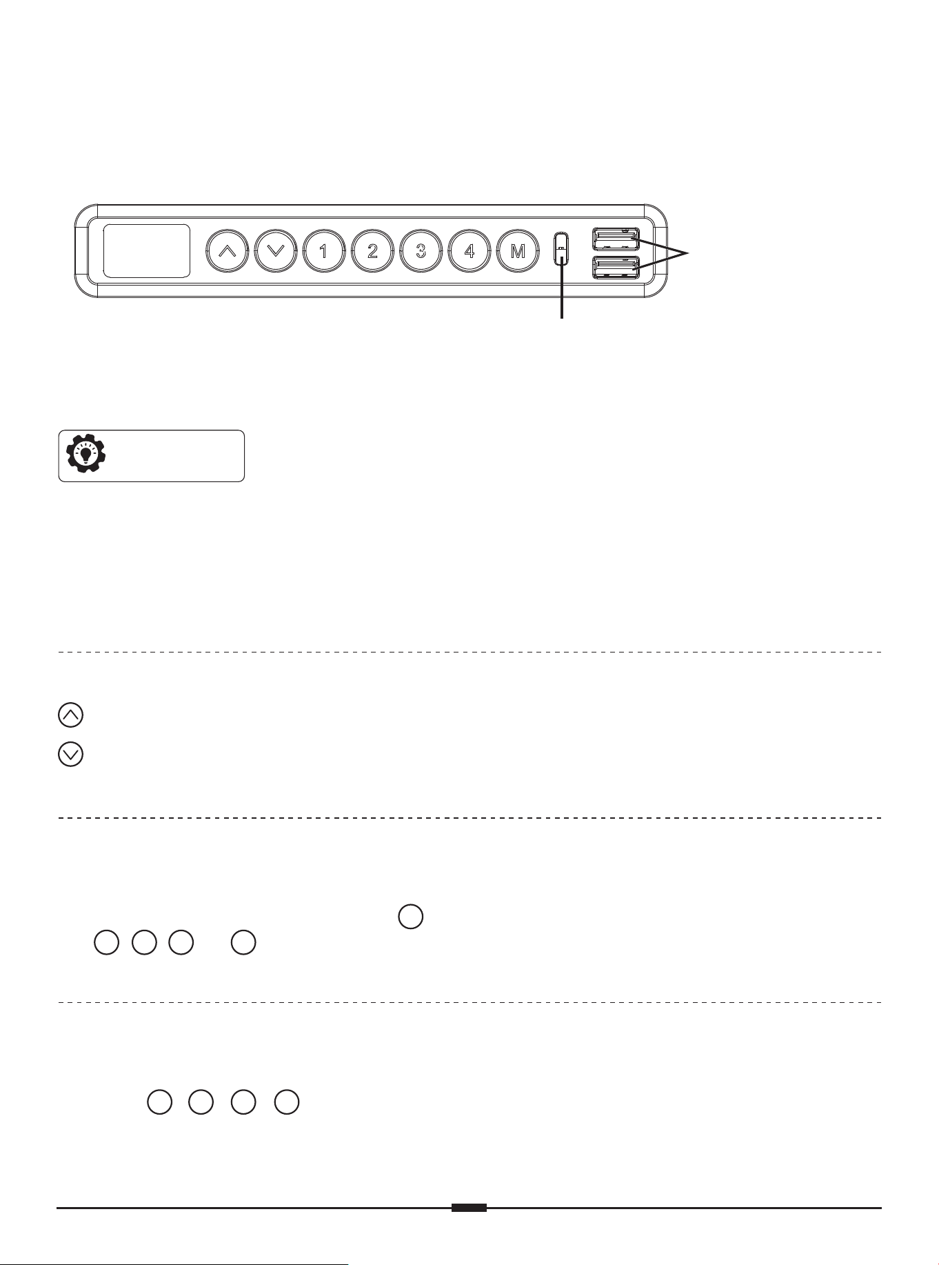
Reset before
first use.
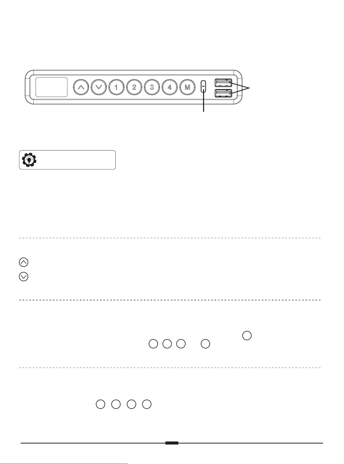
• Save Current Height Setting
Four heights can be saved. Press the button and the screen will display ‘S-’. Press
the , , , or button, the current height will be saved to that button.
• Select Height Setting
Press the / / / button. The desk will move to the height that was previously
set for that button. Press any button to stop the desk.
Using the Controller
Note: Ensure that there are no obstacles when using the desk, that the desktop is not
too close to the wall, and that all cables are long enough for the desk to move up and
down freely. When the controller screen is off (power-saving mode), press any button
to wake it before operation.
Raise Desk (Max height: 46.5”/118cm)
Lower Desk (Min height: 27.6”/70cm)
M
1 2 3 4
1 2 3 4
Each USB-A Output
(5V 2A)
USB-C Output
(9V 2A)
01 02 03 04 05 06 07 08 09 10
11 12 13 14 15 16
17 18 19
20 21 22 23 24 25 26 27 28 29
30 31 32 33 34 35 36 37 38
39 40 41 42 43 44 45 46 47 48
49 50 51 52 53 54 55 56 57
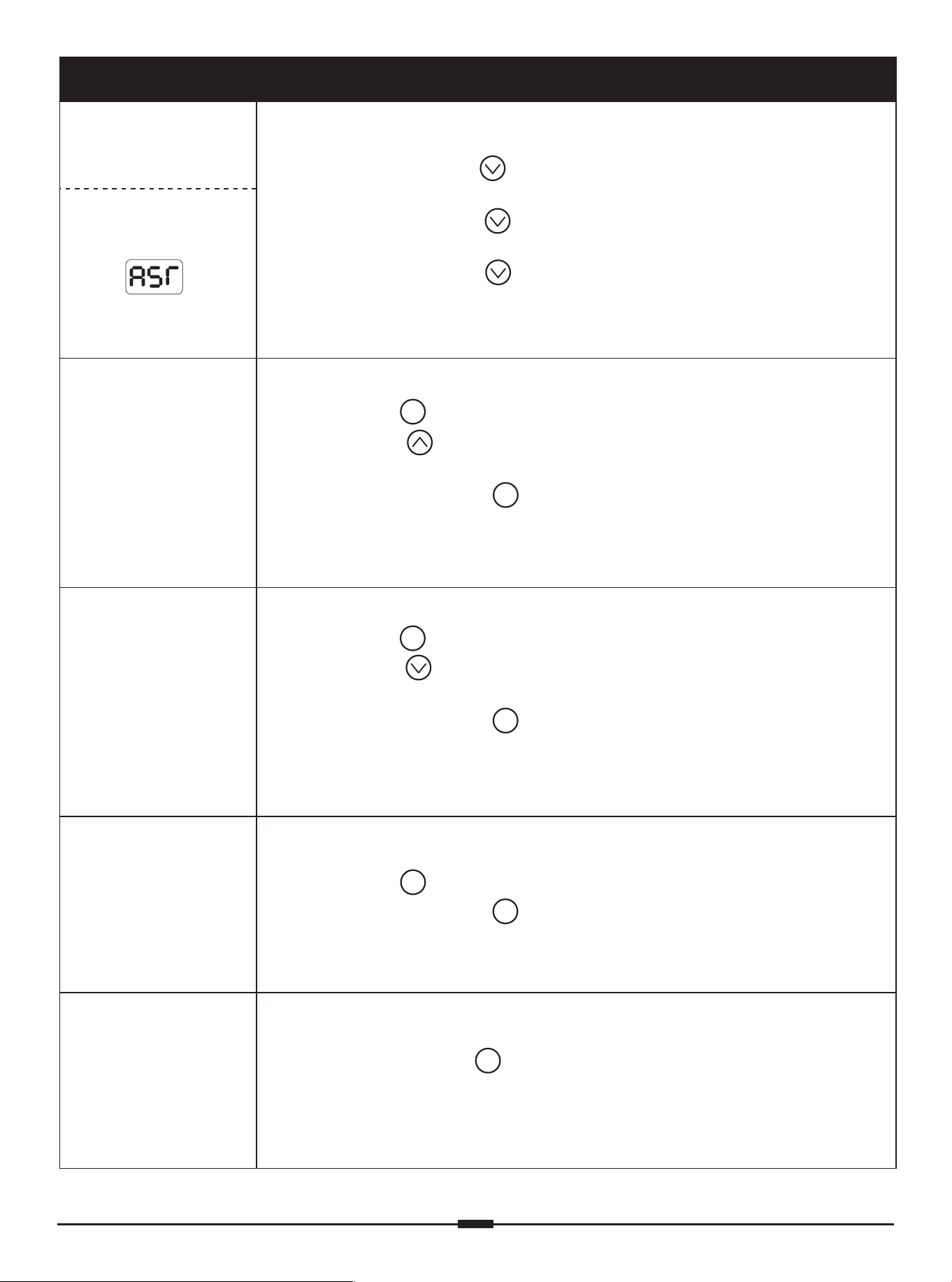
Main Settings
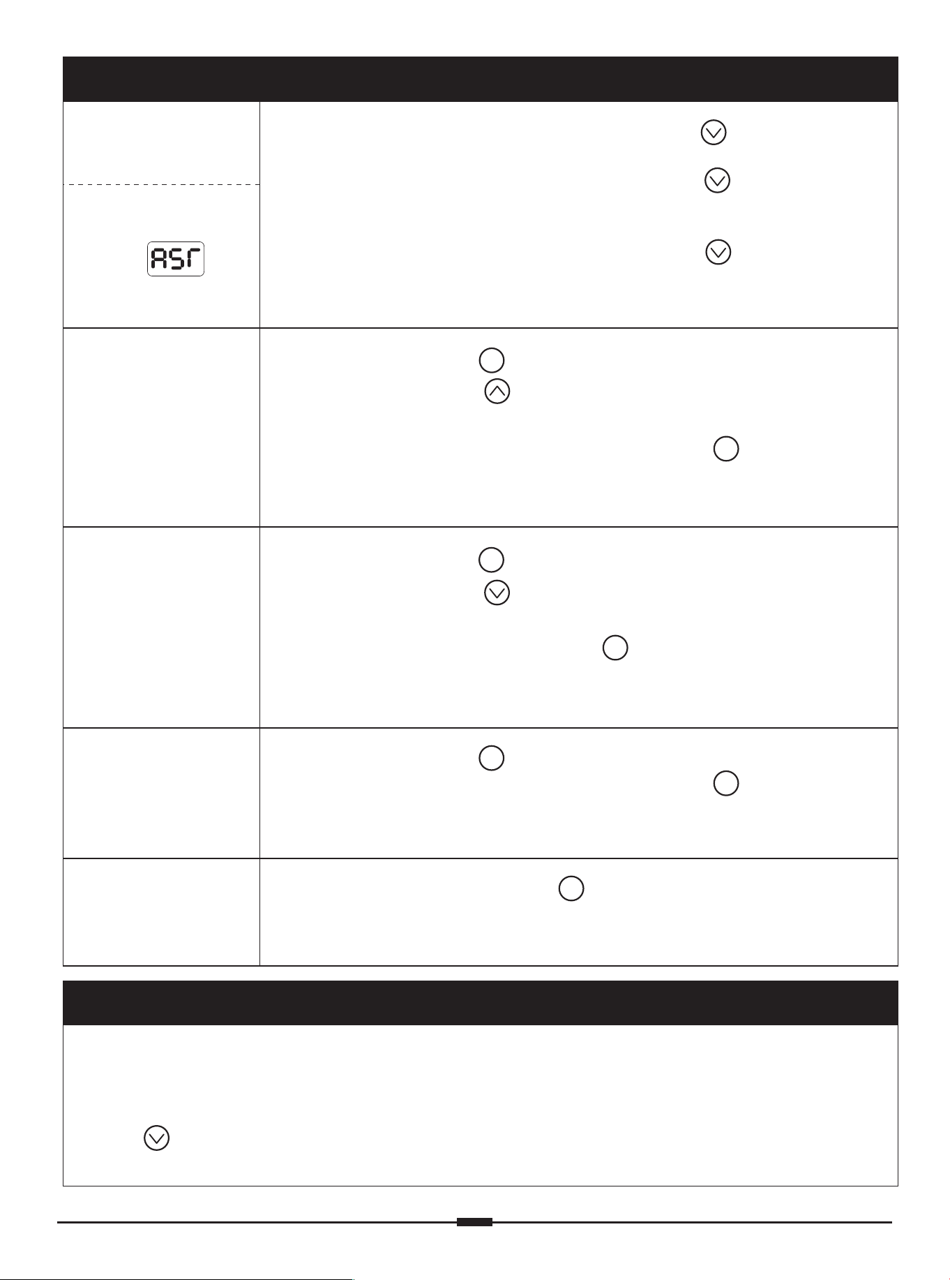
Reset
'RST' displays
as on
the screen.
'RST' displays
as on
the screen.
1. Press and hold the button until the desk goes down to its
lowest level, then release the button.
2. Press and hold the button for 5 seconds until the screen
displays 'RST', then release the button.
3. Press and hold the button again until the screen display
current height again. Reset is complete.
1. Press the button and the screen will display 'S-'.
2. Press the button, the 'S-' will flash once on the screen,
then release the button.
3. Press and hold the button for 2 seconds until the screen
display '999'. The current height will be saved as the highest
limit.
1. Press the button and the screen will display 'S-'.
2. Press the button, the 'S-' will flash once on the screen,
then release the button.
3. Press and hold the button for 2 seconds until the screen
display '00.0'. The current height will be saved as the lowest
limit.
Set Highest Limit
Set Lowest Limit
1. Press the button and the screen will display 'S-'.
2. Press and hold the button for 2 seconds until the screen
display '555'. The highest/lowest limit will be cleared.
Clear Highest/
Lowest Limit
Press and hold the button for 8 seconds to turn the lock on.
The screen will display ‘LOC’, and the buttons will be disabled.
Repeat to turn the lock off.
Lock/Unlock
M
M
M
M
M
M
M
01 02 03 04 05 06 07 08 09 10
11 12 13 14 15 16 17
18
19
20 21 22 23 24 25 26 27 28 29
30 31 32 33 34 35 36 37 38
39 40 41 42 43 44 45 46 47 48
49 50 51 52 53 54 55 56 57
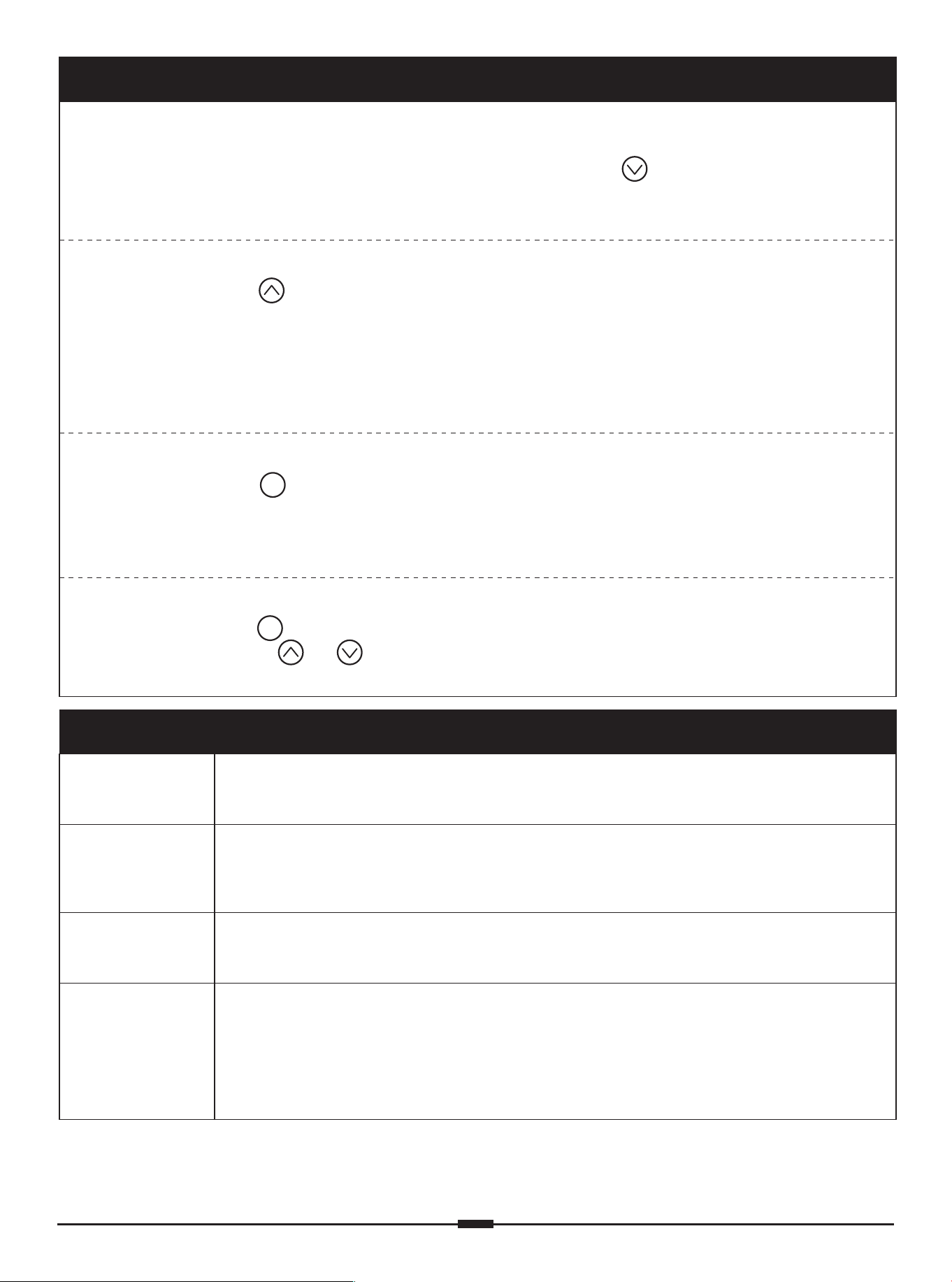
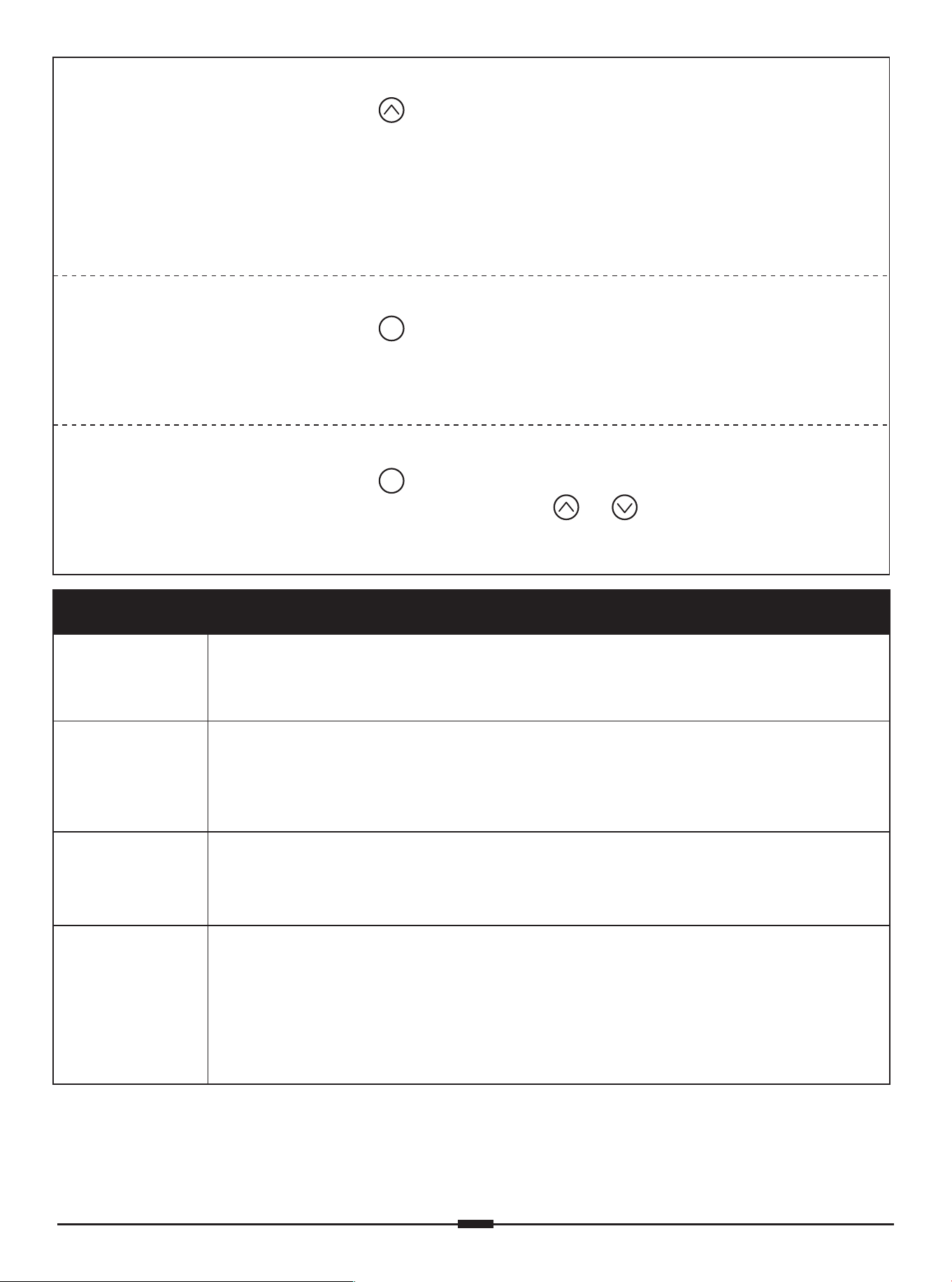
Protection Mode Error Codes
E01
Overcurrent Protection: Input current too high. If the correct AC
adapter is being used, perform a reset before continue using.
E07
Sensor Malfunction Warning: Motor safety sensor cannot be
detected. Power off, check motor cable and power cable
connections, power back on again, then reset.
E12
Undervoltage Protection: Input voltage too low. If the correct AC
adapter is being used, perform a reset before continue using.
H01
Overheating Protection: When the motor overheats or the motor
has been working continuously for too long (total 2.5 minutes in
20 minutes), it will stop operating to prevent damage from
overheating. Wait at least 18 minutes or until the motor cools
down before making any further height adjustment.
Please try resetting the controller if you have any issues including the following:
• Abnormal operation.
• The controller screen displays an error message.
• Change Display Height Units
Press and hold the button for 5 seconds to switch the display height units. The
default unit is imperial.
10.3: Metric (cm)
10.4: Imperial (inch)
• Change Displayed Minimum Height
Press and hold the button for 5 seconds. The current minimum height will flash on
the screen. Press the or button to adjust the minimum height, then release
the button. After 5 seconds, the screen will display ‘RST’ again.
Other Settings
• Change Collision Detection Sensitivity
To adjust the settings below, follow the reset instructions until the display flashes
‘RST’. Next, follow the instructions below to adjust individual settings. After adjustment,
the screen will flash 'RST' again. To exit, press and hold the button until the desk
goes down to its lowest level and comes back up slightly. The screen will display the
current height.
Press and hold the button for 5 seconds to switch sensitivity level.
10.5: High Sensitivity
10.6: Medium Sensitivity
10.7: Low Sensitivity
Note: Sensitivity is preset to Normal (Low Sensitivity) by the factory. However,
sensitivity may be adjusted if needed.
M
2
01 02 03 04 05 06 07 08 09 10
11 12 13 14 15 16 17 18
19
20 21 22 23 24 25 26 27 28 29
30 31 32 33 34 35 36 37 38
39 40 41 42 43 44 45 46 47 48
49 50 51 52 53 54 55 56 57
Spécifications
Max. Charge
154 livres / 70kg (Bureau + Autres articles)
x 11x 11
Le poids du moniteur :
14 livres / 6,3kg
154 livres
(70kg)
Plage de réglage en hauteur
27,6–46,5” (70-118cm)
Max. Vitesse
18mm/s
Entrée d'alimentation
100V-240V
01 02 03 04 05 06 07 08 09 10
11 12 13 14 15 16 17 18 19
20 21 22 23 24 25 26 27 28 29
30 31 32 33 34 35 36 37 38
39 40 41 42 43 44 45 46 47 48
49 50 51 52 53 54 55 56 57
Étape 1
Pièces et matériel fournis
Outils nécessaires (Non compris)
Barre transversale
01
x 1
Pied R
04
x 1
Pied L
03
x 1
Base de la jambe
07
x 2
Plaque latérale
08
x 2
Tige de transmission
06
x 1
Coupleur de tige
K2
x 1
Tige de transmission
05
x 1
Moteur
02
x 1
K1
x 2
Vis de réglage
A
x 8
Boulon
M6 x 30mm
B
x 10
Boulon
M6 x 10mm
Clé
I
x 1
C
x 1
Clé Allen
5/32” (4mm)
01 02 03 04 05 06 07 08 09 10
11 12 13 14 15 16 17 18 19
20
21 22 23 24 25 26 27 28 29
30 31 32 33 34 35 36 37 38
39 40 41 42 43 44 45 46 47 48
49 50 51 52 53 54 55 56 57
Clip de câble
H
x 4
14
x 1
Câble d'alimentation
(877) 419-7832 Mon-Fri 8am - 8pm (CST)
support@ergoav.com
Tout le matériel inclus dans ce package ne sera pas utilisé.
15
x 1
09
x 2
10
x 1
11
x 1
Bureau
C
x 1
D
x 14
12
x 1
Panneau de
support du tiroir
13
x 1
Panneau de
support du tiroir
L2
x 4
L1
x 4
G
x 2
Étape 2
Pièces et matériel fournis
Étape 3
Pièces et matériel fournis
Étape 4
Pièces et matériel fournis
Si vous recevez des pièces qui sont endommagées,
défectueuses ou auxquelles il manque des éléments,
veuillez nous contacter.
Nous Contacter
Support de
plateau
Plateau de gestion
des câbles
Tiroir
Clé Allen
5/32” (4mm)
Boulon
M6 x 14mm
Boulon à cameCheville à bois Verrou à came
La pièce réelle
peut varier.
01 02 03 04 05 06 07 08 09 10
11 12 13 14 15 16 17 18 19
20 21
22 23 24 25 26 27 28 29
30 31 32 33 34 35 36 37 38
39 40 41 42 43 44 45 46 47 48
49 50 51 52 53 54 55 56 57
Étape 1
Assemblage du cadre
04
05
04
Connectez la tige de transmission courte au pied R.
B
x 2
M6 x 10mm
5/32” (4mm)
C
x 1
01
01 02 03 04 05 06 07 08 09 10
11 12 13 14 15 16 17 18 19
20 21 22
23 24 25 26 27 28 29
30 31 32 33 34 35 36 37 38
39 40 41 42 43 44 45 46 47 48
49 50 51 52 53 54 55 56 57
B
x 2
M6 x 10mm
5/32” (4mm)
C
x 1
03
5/32” (4mm)
C
x 1
A
x 8
M6 x 30mm
07
07
01 02 03 04 05 06 07 08 09 10
11 12 13 14 15 16 17 18 19
20 21 22 23
24 25 26 27 28 29
30 31 32 33 34 35 36 37 38
39 40 41 42 43 44 45 46 47 48
49 50 51 52 53 54 55 56 57
B
x 4
M6 x 10mm
5/32” (4mm)
C
x 1
08
08
Assurez-vous que les patins en caoutchouc sont fixés au cadre. Si certains se sont
détachés, réattachez-les ou utilisez les patins en caoutchouc de rechange.
Grands patins en caoutchouc
180°
01 02 03 04 05 06 07 08 09 10
11 12 13 14 15 16 17 18 19
20 21 22 23 24
25 26 27 28 29
30 31 32 33 34 35 36 37 38
39 40 41 42 43 44 45 46 47 48
49 50 51 52 53 54 55 56 57
K2
x 1
02
Assurez-vous que les trous
pour les vis de réglage sont
orientés vers le haut.
Insérez le moteur dans
la tige de transmission
mais ne le fixez pas.
OngletOnglet
01 02 03 04 05 06 07 08 09 10
11 12 13 14 15 16 17 18 19
20 21 22 23 24 25
26 27 28 29
30 31 32 33 34 35 36 37 38
39 40 41 42 43 44 45 46 47 48
49 50 51 52 53 54 55 56 57
I
x 1
06
Ajustez les pieds inégaux du bureau si nécessaire :
Mesurez la hauteur de chaque pied pour vérifier s'ils sont réglés au même niveau. Sinon,
tournez la tige pour lever ou abaisser la jambe jusqu'à ce qu'elle soit au niveau de la
jambe avec moteur.
Assurez-vous que l'extrémité
de la tige de transmission
insérée dans le pied.
01 02 03 04 05 06 07 08 09 10
11 12 13 14 15 16 17 18 19
20 21 22 23 24 25 26
27 28 29
30 31 32 33 34 35 36 37 38
39 40 41 42 43 44 45 46 47 48
49 50 51 52 53 54 55 56 57
K1
x 2
I
x 1
5/32” (4mm)
C
x 1
Assurez-vous que
les tiges sont sous
ces trous de vis.
Si la tige de transmission ne
s'ajuste pas correctement,
utilisez la clé pour ajuster
finement la position.
01 02 03 04 05 06 07 08 09 10
11 12 13 14 15 16 17 18 19
20 21 22 23 24 25 26 27
28 29
30 31 32 33 34 35 36 37 38
39 40 41 42 43 44 45 46 47 48
49 50 51 52 53 54 55 56 57
B
x 2
M6 x 10mm
5/32” (4mm)
C
x 1
01 02 03 04 05 06 07 08 09 10
11 12 13 14 15 16 17 18 19
20 21 22 23 24 25 26 27 28
29
30 31 32 33 34 35 36 37 38
39 40 41 42 43 44 45 46 47 48
49 50 51 52 53 54 55 56 57
D
x 10
M6 x 14mm
5/32” (4mm)
C
x 1
La tige de transmission
fait face à l'avant.
AvantAvant
Tige de transmissionTige de transmission
Étape 2
Fixation du bureau et des autres pièces
Conseil : indiquez les emplacements des trous pré-percés.
HautHaut
BasBas
11
11
01 02 03 04 05 06 07 08 09 10
11 12 13 14 15 16 17 18 19
20 21 22 23 24 25 26 27 28 29
30 31 32 33 34 35 36 37 38
39 40 41 42 43 44 45 46 47 48
49 50 51 52 53 54 55 56 57
D
x 4
M6 x 14mm
5/32” (4mm)
C
x 1
09
09
10
01 02 03 04 05 06 07 08 09 10
11 12 13 14 15 16 17 18 19
20 21 22 23 24 25 26 27 28 29
30
31 32 33 34 35 36 37 38
39 40 41 42 43 44 45 46 47 48
49 50 51 52 53 54 55 56 57
L1
x 4
G
x 2
01 02 03 04 05 06 07 08 09 10
11 12 13 14 15 16 17 18 19
20 21 22 23 24 25 26 27 28 29
30 31
32 33 34 35 36 37 38
39 40 41 42 43 44 45 46 47 48
49 50 51 52 53 54 55 56 57
L2
x 4
180°
AvantAvant
13
12
13
12
01 02 03 04 05 06 07 08 09 10
11 12 13 14 15 16 17 18 19
20 21 22 23 24 25 26 27 28 29
30 31 32
33 34 35 36 37 38
39 40 41 42 43 44 45 46 47 48
49 50 51 52 53 54 55 56 57
H
x 4
Un exemple de disposition de clips de câble est indiqué ci-dessous. Cependant,
les clips de câble peuvent être disposées selon vos besoins.
Étape 3
Connexion des câbles
Câble de moteurCâble de moteur
Câble de moteurCâble de moteur
Câble de contrôleurCâble de contrôleur
14
14
01 02 03 04 05 06 07 08 09 10
11 12 13 14 15 16 17 18 19
20 21 22 23 24 25 26 27 28 29
30 31 32 33
34 35 36 37 38
39 40 41 42 43 44 45 46 47 48
49 50 51 52 53 54 55 56 57
Ne laissez pas le contrôleur entrer en collision avec le sol en retournant le bureau,
ce qui pourrait causer des dommages.
Étape 4
Fixation du tiroir
Si vous devez retirer le tiroir,
appuyez simultanément sur
une languette vers le haut et
l'autre vers le bas.
Retourner à
180°
①
②
15
01 02 03 04 05 06 07 08 09 10
11 12 13 14 15 16 17 18 19
20 21 22 23 24 25 26 27 28 29
30 31 32 33 34
35 36 37 38
39 40 41 42 43 44 45 46 47 48
49 50 51 52 53 54 55 56 57
• Enregistrer le réglage actuel de la hauteur
• Sélectionner le réglage de hauteur
Appuyez sur le bouton / / / . Le bureau se déplacera à la hauteur
précédemment définie pour ce bouton. Appuyez sur n'importe quel bouton pour
arrêter le bureau.
Utilisation du contrôleur
Abaissez le bureau (Hauteur minimale : 27,6”/70cm)
M
1 2 3 4
1 2 3 4
Sortie USB-C
(9V 2A)
Chaque sortie
USB-A (5V 2A)
Élevez le bureau (Hauteur maximale : 46,5”/118cm)
Remarque : Assurez-vous qu'il n'y a pas d'obstacles lors de l'utilisation du bureau, que
le plateau n'est pas trop près du mur et que tous les câbles sont suffisamment longs
pour permettre au bureau de monter et descendre librement. Lorsque l'écran du
contrôleur est éteint (mode économie d'énergie), appuyez sur n'importe quel bouton
pour le réveiller avant l'opération.
Quatre hauteurs peuvent être enregistrées. Appuyez sur le bouton et l'écran
affichera « S- ». Appuyez sur le bouton , , , ou , la hauteur actuelle sera
enregistrée sur ce bouton.
Réinitialiser avant la
première utilisation.
01 02 03 04 05 06 07 08 09 10
11 12 13 14 15 16 17 18 19
20 21 22 23 24 25 26 27 28 29
30 31 32 33 34 35
36 37 38
39 40 41 42 43 44 45 46 47 48
49 50 51 52 53 54 55 56 57
Paramètres principaux
Réinitialiser
'RST' s'affiche
comme
à l'écran.
'RST' s'affiche
comme
à l'écran.
1. Appuyez sur le bouton et l'écran affichera 'S-'.
2. Appuyez sur le bouton , le 'S-' clignotera une fois à
l'écran, puis relâchez le bouton.
3. Appuyez et maintenez le bouton pendant 2 secondes
jusqu'à ce que l'écran affiche '999'. La hauteur actuelle sera
enregistrée comme la limite maximale.
1. Appuyez sur le bouton et l'écran affichera 'S-'.
2. Appuyez sur le bouton , le 'S-' clignotera une fois à
l'écran, puis relâchez le bouton.
3. Appuyez et maintenez le bouton pendant 2 secondes
jusqu'à ce que l'écran affiche '00.0'. La hauteur actuelle sera
enregistrée comme la limite minimale.
Définir la limite
maximale
Définir la limite
minimale
Appuyez et maintenez le bouton pendant 8 secondes pour
activer le verrou. L'écran affichera 'LOC' et les boutons seront
désactivés. Répétez pour désactiver le verrou.
Verrouiller/
Déverrouiller
Autres paramètres
Pour ajuster les paramètres ci-dessous, suivez les instructions de réinitialisation
jusqu'à ce que l'affichage clignote « RST ». Ensuite, suivez les instructions ci-dessous
pour ajuster les paramètres individuels. Après réglage, l'écran affichera à nouveau
'RST'. Pour sortir, appuyez et maintenez le bouton jusqu'à ce que le bureau
descende à son niveau le plus bas et remonte légèrement. L'écran affichera la
hauteur actuelle.
M
M
M
M
M
M
M
1. Appuyez sur le bouton et l'écran affichera 'S-'.
2. Appuyez et maintenez le bouton pendant 2 secondes
jusqu'à ce que l'écran affiche '555'. La limite la plus haute/la
plus basse sera effacée.
1. Appuyez et maintenez le bouton jusqu'à ce que le bureau
descende à son niveau le plus bas, puis relâchez le bouton.
2. Appuyez et maintenez le bouton pendant 5 secondes
jusqu'à ce que l'écran affiche 'RST', puis relâchez le bouton.
3. Appuyez et maintenez le bouton jusqu'à ce que l'écran
affiche à nouveau la hauteur actuelle. La réinitialisation est
terminée.
Effacer Limite
Maximale/
Minimale
01 02 03 04 05 06 07 08 09 10
11 12 13 14 15 16 17 18 19
20 21 22 23 24 25 26 27 28 29
30 31 32 33 34 35 36
37 38
39 40 41 42 43 44 45 46 47 48
49 50 51 52 53 54 55 56 57
Codes d'erreur du mode de protection
E01
E07
E12
Protection contre la sous-tension : Tension d'entrée trop basse. Si
l'adaptateur AC correct est utilisé, effectuez une réinitialisation
avant de continuer à l'utiliser.
H01
Veuillez essayer de réinitialiser le contrôleur si vous rencontrez des problèmes, y
compris les suivants :
• Fonctionnement anormal.
• L'écran du contrôleur affiche un message d'erreur.
• Modifier les unités de hauteur d'affichage
Appuyez et maintenez le bouton pendant 5 secondes pour changer les unités de
hauteur de l'affichage. L'unité par défaut est impériale.
10,3 : Métrique (cm)
10,4 : Impérial (pouce)
• Modifier la hauteur minimale affichée
• Modifier la sensibilité de détection des collisions
Appuyez et maintenez le bouton pendant 5 secondes pour changer le niveau
de sensibilité.
10.5 : Haute sensibilité
10.6 : Sensibilité moyenne
10.7 : Faible sensibilité
Remarque : La sensibilité est préréglée sur Normal (Faible sensibilité) par l'usine.
Cependant, la sensibilité peut être ajustée si nécessaire.
M
2
Appuyez et maintenez le bouton pendant 5 secondes. La hauteur minimale
actuelle clignotera à l'écran. Appuyez sur le bouton ou pour ajuster la hauteur
minimale, puis relâchez le bouton. Après 5 secondes, l'écran affichera à nouveau
'RST'.
Protection contre la surchauffe : Lorsque le moteur surchauffe
ou fonctionne en continu trop longtemps (2,5 minutes au total
en 20 minutes), il s'arrête pour éviter les dommages dus à la
surchauffe. Attendez au moins 18 minutes ou jusqu'à ce que le
moteur refroidisse avant d'effectuer tout autre réglage de
hauteur.
Avertissement de dysfonctionnement du capteur : Le capteur
de sécurité du moteur ne peut pas être détecté. Éteindre,
vérifier les connexions du câble moteur et du câble
d'alimentation, rallumer, puis réinitialiser.
Protection contre les surintensités : Courant d'entrée trop élevé.
Si l'adaptateur AC correct est utilisé, effectuez une
réinitialisation avant de continuer à l'utiliser.
01 02 03 04 05 06 07 08 09 10
11 12 13 14 15 16 17 18 19
20 21 22 23 24 25 26 27 28 29
30 31 32 33 34 35 36 37
38
39 40 41 42 43 44 45 46 47 48
49 50 51 52 53 54 55 56 57
Especificaciones
Carga máxima
154 libras / 70kg (Escritorio + Otros artículos)
x 11x 11
El peso del monitor:
14 libras / 6.3kg
154 libras
(70kg)
Rango de ajuste de altura
27.6–46.5'' (70-118cm)
Máx. Velocidad
18mm/s
Entrada de energía
100V-240V
01 02 03 04 05 06 07 08 09 10
11 12 13 14 15 16 17 18 19
20 21 22 23 24 25 26 27 28 29
30 31 32 33 34 35 36 37 38
39 40 41 42 43 44 45 46 47 48
49 50 51 52 53 54 55 56 57
Paso 1
Piezas suministradas y artículos de ferretería
Herramientas necesarias (No incluído)
Barra transversal
01
x 1
Pata D
04
x 1
Pata Izq
03
x 1
Base de la Pata
07
x 2
Placa lateral
08
x 2
Barra de transmisión
06
x 1
Acoplador de barra
K2
x 1
Barra de transmisión
05
x 1
Motor
02
x 1
K1
x 2
Tornillo prisionero
A
x 8
Perno
M6 x 30mm
B
x 10
Perno
M6 x 10mm
Llave
I
x 1
C
x 1
Llave Allen
5/32” (4mm)
01 02 03 04 05 06 07 08 09 10
11 12 13 14 15 16 17 18 19
20 21 22 23 24 25 26 27 28 29
30 31 32 33 34 35 36 37 38
39
40 41 42 43 44 45 46 47 48
49 50 51 52 53 54 55 56 57
Clip para cables
H
x 4
14
x 1
Cable de alimentación
(877) 419-7832 Mon-Fri 8am - 8pm (CST)
support@ergoav.com
Not all hardware included in this package will be used.
15
x 1
09
x 2
10
x 1
11
x 1
Escritorio
C
x 1
D
x 14
12
x 1
Panel de
soporte del cajón
13
x 1
Panel de
soporte del cajón
L2
x 4
L1
x 4
G
x 2
Paso 3
Piezas suministradas y artículos de ferretería
Paso 4
Piezas suministradas y artículos de ferretería
Si recibe piezas que están dañadas, defectuosas o a
las que les faltan partes, por favor contáctenos.
Contáctenos
Paso 2
Piezas suministradas y artículos de ferretería
Soporte de
bandeja
Bandeja de
gestión de cables
Cajón
Llave Allen
5/32” (4mm)
Perno
M6 x 14mm
Cerrojo
de leva
Pasador
de madera
Cerradura
de leva
La pieza real
puede variar.
01 02 03 04 05 06 07 08 09 10
11 12 13 14 15 16 17 18 19
20 21 22 23 24 25 26 27 28 29
30 31 32 33 34 35 36 37 38
39 40
41 42 43 44 45 46 47 48
49 50 51 52 53 54 55 56 57
Paso 1
Ensamblando el Marco
04
05
04
Conecte la barra de transmisión corta a la pata R.
B
x 2
M6 x 10mm
5/32” (4mm)
C
x 1
01
01 02 03 04 05 06 07 08 09 10
11 12 13 14 15 16 17 18 19
20 21 22 23 24 25 26 27 28 29
30 31 32 33 34 35 36 37 38
39 40 41
42 43 44 45 46 47 48
49 50 51 52 53 54 55 56 57
B
x 2
M6 x 10mm
5/32” (4mm)
C
x 1
03
5/32” (4mm)
C
x 1
A
x 8
M6 x 30mm
07
07
01 02 03 04 05 06 07 08 09 10
11 12 13 14 15 16 17 18 19
20 21 22 23 24 25 26 27 28 29
30 31 32 33 34 35 36 37 38
39 40 41 42
43 44 45 46 47 48
49 50 51 52 53 54 55 56 57
B
x 4
M6 x 10mm
5/32” (4mm)
C
x 1
08
08
Asegúrate de que las almohadillas de goma estén sujetas al marco. Si alguno se ha
desprendido, vuelve a colocarlo o usa las almohadillas de goma de repuesto.
Almohadillas Altas de Goma
180°
01 02 03 04 05 06 07 08 09 10
11 12 13 14 15 16 17 18 19
20 21 22 23 24 25 26 27 28 29
30 31 32 33 34 35 36 37 38
39 40 41 42 43
44 45 46 47 48
49 50 51 52 53 54 55 56 57
K2
x 1
02
Asegúrese de que los agujeros
para los tornillos de fijación
estén orientados hacia arriba.
Inserte el motor en la
barra de transmisión
pero no lo asegure.
PestañaPestaña
01 02 03 04 05 06 07 08 09 10
11 12 13 14 15 16 17 18 19
20 21 22 23 24 25 26 27 28 29
30 31 32 33 34 35 36 37 38
39 40 41 42 43 44
45 46 47 48
49 50 51 52 53 54 55 56 57
I
x 1
06
Mide la altura de cada pata para ver si están al mismo nivel. Si no, gira la varilla para
subir o bajar la pata hasta que esté nivelada con la pata con motor.
Ajusta las patas desiguales del escritorio si es necesario:
Asegúrese de que el extremo de
la barra esté completamente
insertado en la pata.
01 02 03 04 05 06 07 08 09 10
11 12 13 14 15 16 17 18 19
20 21 22 23 24 25 26 27 28 29
30 31 32 33 34 35 36 37 38
39 40 41 42 43 44 45
46 47 48
49 50 51 52 53 54 55 56 57
K1
x 2
I
x 1
5/32” (4mm)
C
x 1
Si la barra de transmisión
no encaja suavemente,
usa la llave para ajustar
finamente la posición.
Asegúrate de que las
barras estén debajo
de estos agujeros de
tornillos.
01 02 03 04 05 06 07 08 09 10
11 12 13 14 15 16 17 18 19
20 21 22 23 24 25 26 27 28 29
30 31 32 33 34 35 36 37 38
39 40 41 42 43 44 45 46
47 48
49 50 51 52 53 54 55 56 57
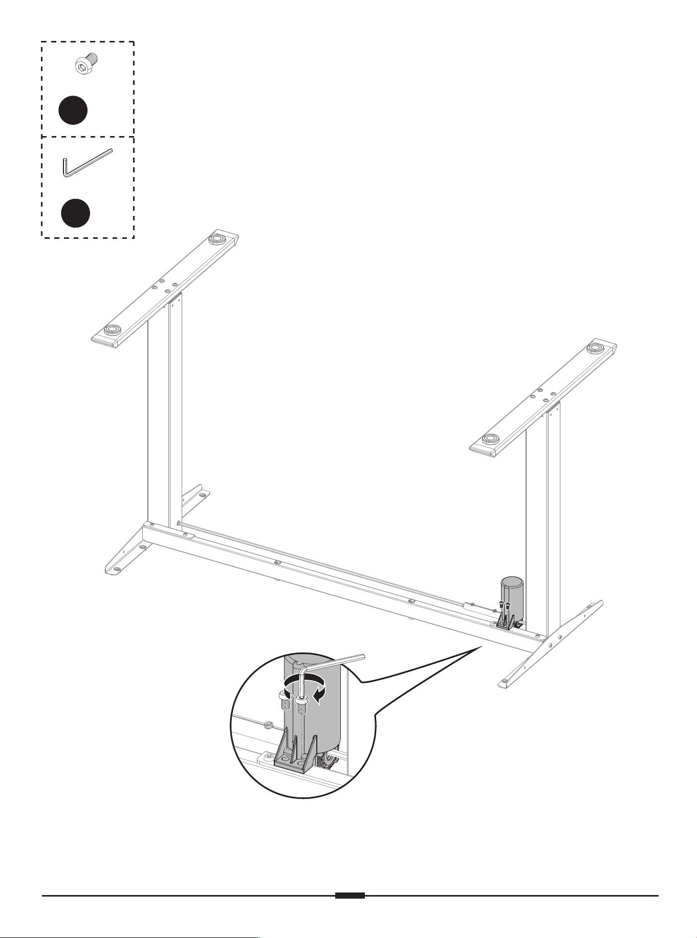
B
x 2
M6 x 10mm
5/32” (4mm)
C
x 1
01 02 03 04 05 06 07 08 09 10
11 12 13 14 15 16 17 18 19
20 21 22 23 24 25 26 27 28 29
30 31 32 33 34 35 36 37 38
39 40 41 42 43 44 45 46 47
48
49 50 51 52 53 54 55 56 57
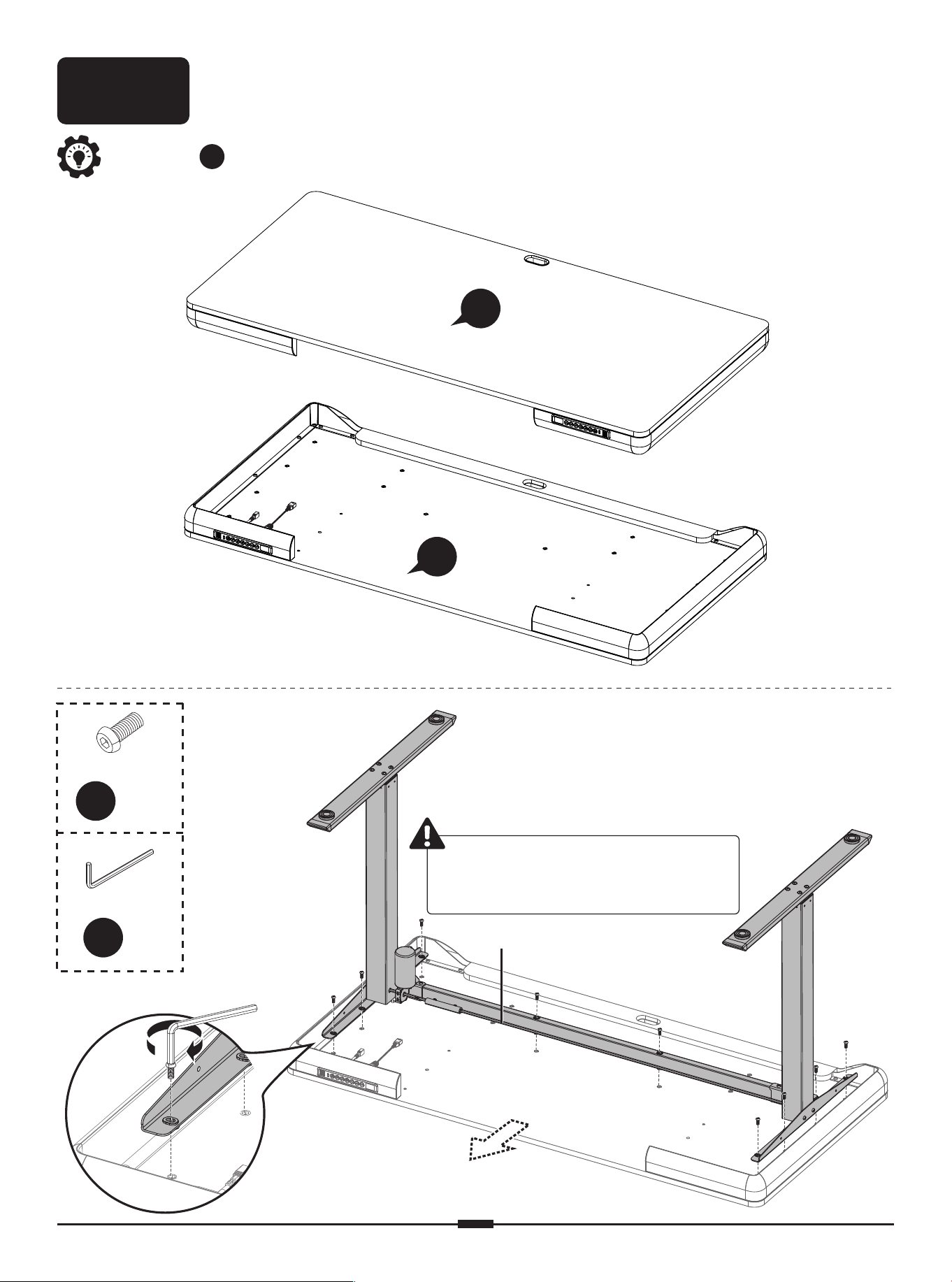
D
x 10
M6 x 14mm
5/32” (4mm)
C
x 1
La barra de transmisión mira
hacia el frente.
FrenteFrente
Barra de transmisiónBarra de transmisión
Paso 2
Adjuntando el Escritorio y Otras Partes
Consejo: indica las ubicaciones de los agujeros preperforados.
SuperiorSuperior
FondoFondo
11
11
01 02 03 04 05 06 07 08 09 10
11 12 13 14 15 16 17 18 19
20 21 22 23 24 25 26 27 28 29
30 31 32 33 34 35 36 37 38
39 40 41 42 43 44 45 46 47 48
49 50 51 52 53 54 55 56 57
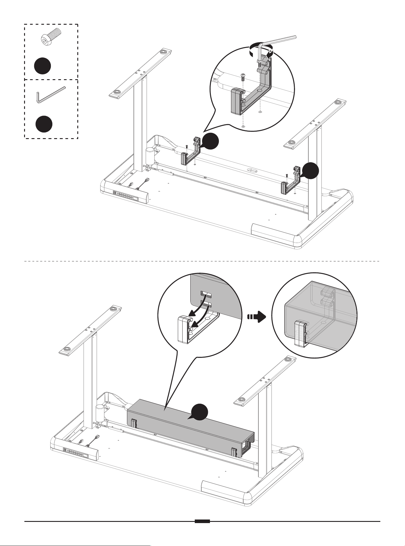
09
09
10
D
x 4
M6 x 14mm
5/32” (4mm)
C
x 1
01 02 03 04 05 06 07 08 09 10
11 12 13 14 15 16 17 18 19
20 21 22 23 24 25 26 27 28 29
30 31 32 33 34 35 36 37 38
39 40 41 42 43 44 45 46 47 48
49
50 51 52 53 54 55 56 57
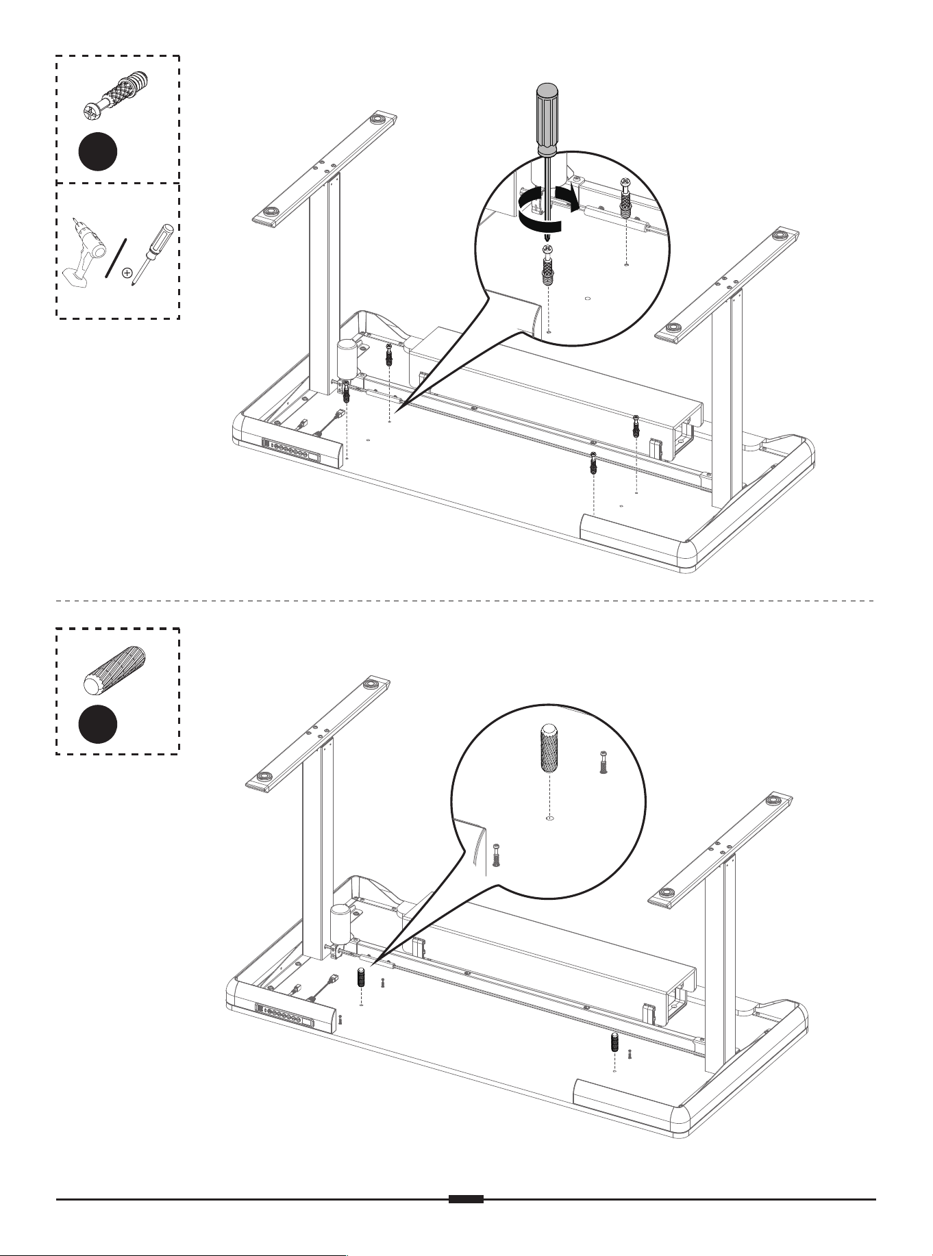
L1
x 4
G
x 2
01 02 03 04 05 06 07 08 09 10
11 12 13 14 15 16 17 18 19
20 21 22 23 24 25 26 27 28 29
30 31 32 33 34 35 36 37 38
39 40 41 42 43 44 45 46 47 48
49 50
51 52 53 54 55 56 57
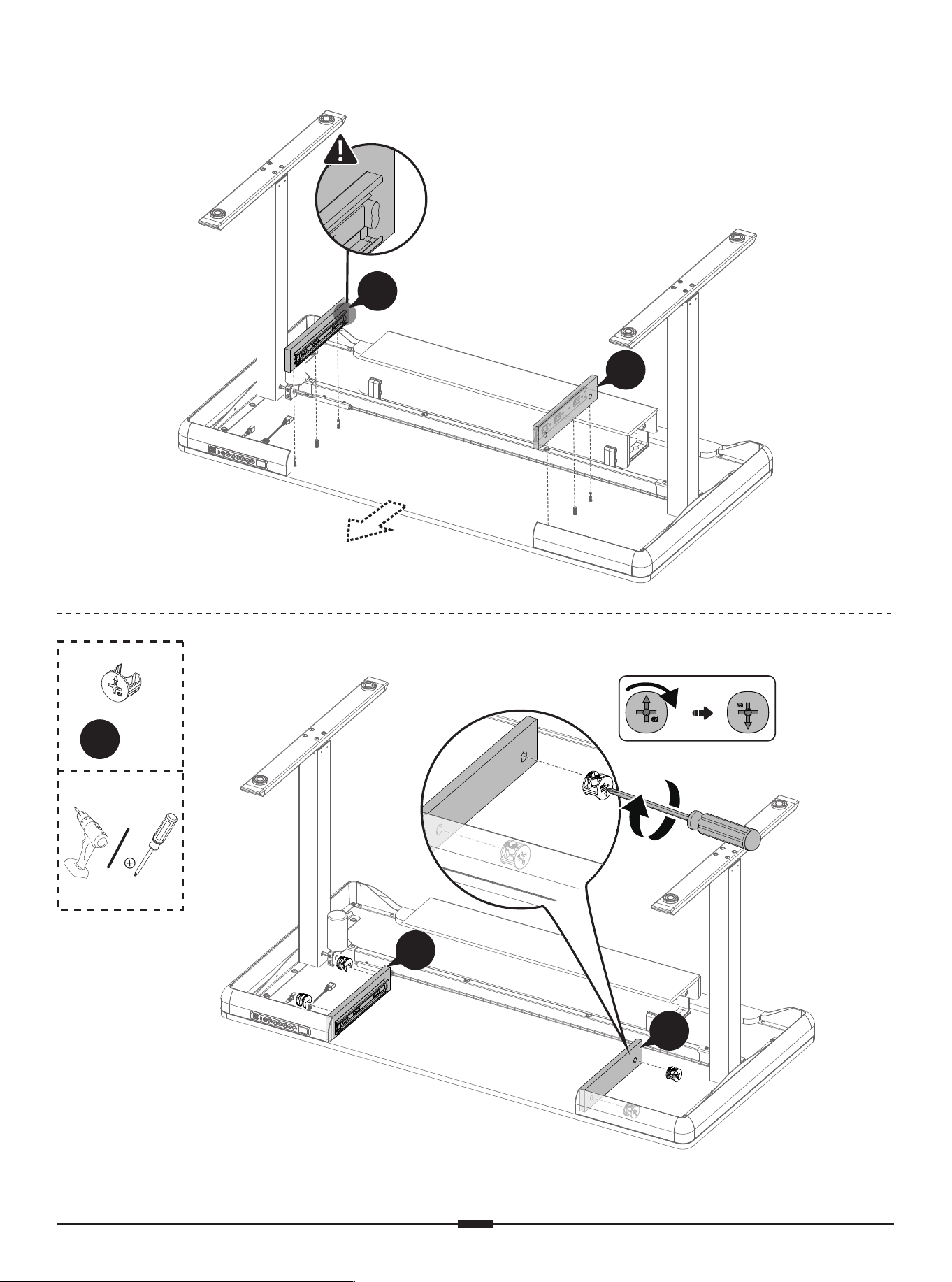
L2
x 4
180°
FrenteFrente
13
12
13
12
01 02 03 04 05 06 07 08 09 10
11 12 13 14 15 16 17 18 19
20 21 22 23 24 25 26 27 28 29
30 31 32 33 34 35 36 37 38
39 40 41 42 43 44 45 46 47 48
49 50 51
52 53 54 55 56 57
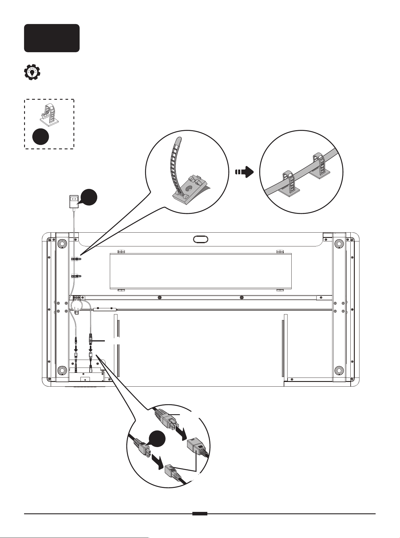
H
x 4
Un ejemplo de disposición de sujetacables se indica a continuación. Sin embargo,
los clips de cable se pueden organizar según sus necesidades.
Paso 3
Conectando los Cables
14
14
Cable del motorCable del motor
Cable del motorCable del motor
Cable del controladorCable del controlador
01 02 03 04 05 06 07 08 09 10
11 12 13 14 15 16 17 18 19
20 21 22 23 24 25 26 27 28 29
30 31 32 33 34 35 36 37 38
39 40 41 42 43 44 45 46 47 48
49 50 51 52
53 54 55 56 57
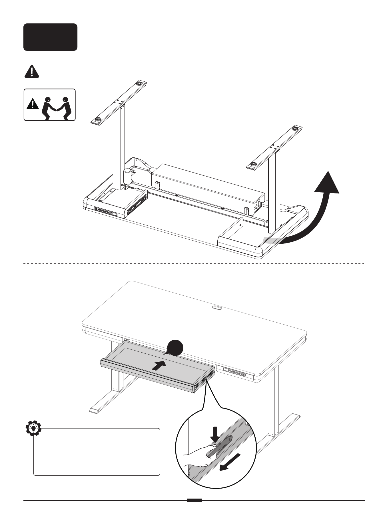
Al voltear el escritorio, no permitas que el controlador choque con el suelo, ya que
podría causar daños.
Paso 4
Adjuntar el cajón
Si necesita quitar el cajón,
presione una pestaña
hacia arriba y la otra hacia
abajo al mismo tiempo.
Girar 180°
①
②
15
01 02 03 04 05 06 07 08 09 10
11 12 13 14 15 16 17 18 19
20 21 22 23 24 25 26 27 28 29
30 31 32 33 34 35 36 37 38
39 40 41 42 43 44 45 46 47 48
49 50 51 52 53
54 55 56 57
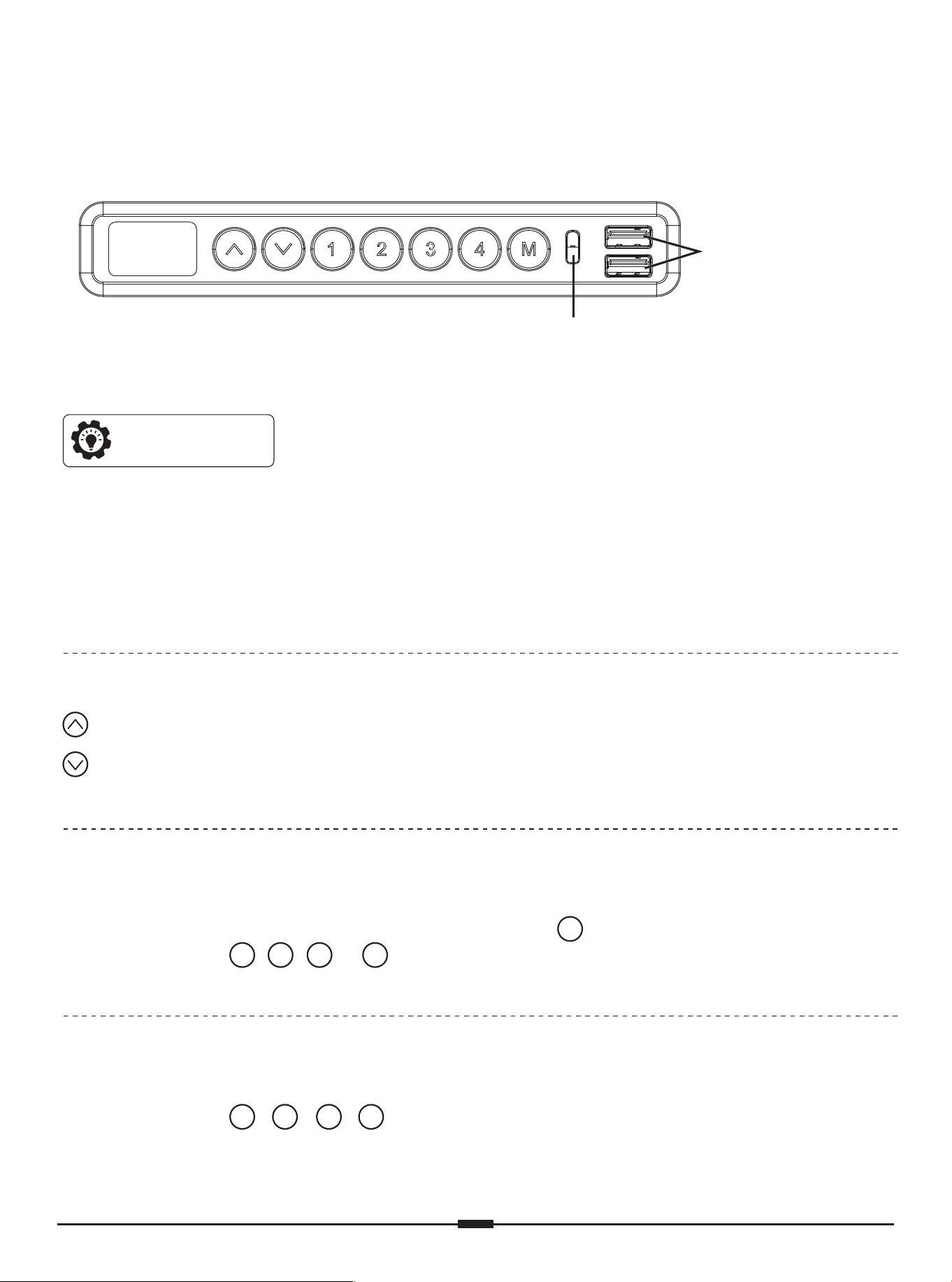
• Guardar Configuración de Altura Actual
Cuatro alturas se pueden guardar. Presiona el botón y la pantalla mostrará ‘S-’.
Presiona el botón , , , o , la altura actual se guardará en ese botón.
• Seleccionar Ajuste de Altura
Presiona el botón / / / . El escritorio se moverá a la altura que se estableció
previamente para ese botón. Presiona cualquier botón para detener el escritorio.
Usando el Controlador
Baja el escritorio (Altura mínima: 27.6”/70cm)
M
1 2 3 4
1 2 3 4
Salida USB-C
(9V 2A)
Cada salida USB-A
(5V 2A)
Eleva el escritorio (Altura máxima: 46.5”/118cm)
Nota: Asegúrese de que no haya obstáculos al usar el escritorio, que la superficie no
esté demasiado cerca de la pared y que todos los cables sean lo suficientemente
largos para que el escritorio se mueva hacia arriba y hacia abajo libremente. Cuando
la pantalla del controlador está apagada (modo de ahorro de energía), presiona
cualquier botón para activarla antes de operar.
Reiniciar antes
del primer uso.
01 02 03 04 05 06 07 08 09 10
11 12 13 14 15 16 17 18 19
20 21 22 23 24 25 26 27 28 29
30 31 32 33 34 35 36 37 38
39 40 41 42 43 44 45 46 47 48
49 50 51 52 53 54
55 56 57
Ajustes principales
Reiniciar
1. Presiona el botón y la pantalla mostrará 'S-'.
2. Presiona el botón , la 'S-' parpadeará una vez en la
pantalla, luego suelta el botón.
3. Presione y mantenga presionado el botón durante 2
segundos hasta que la pantalla muestre '999'. La altura
actual se guardará como el límite máximo.
1. Presiona el botón y la pantalla mostrará 'S-'.
2. Presiona el botón , la 'S-' parpadeará una vez en la
pantalla, luego suelta el botón.
3. Presione y mantenga el botón durante 2 segundos
hasta que la pantalla muestre '00.0'. La altura actual se
guardará como el límite mínimo.
Establecer
Límite Máximo
Establecer
Límite Mínimo
Presiona y mantén el botón durante 8 segundos para
activar el bloqueo. La pantalla mostrará 'LOC' y los botones
estarán desactivados. Repite para desbloquear.
Bloquear/
Desbloquear
Otras Configuraciones
M
M
M
M
M
M
M
Para ajustar la configuración a continuación, siga las instrucciones de reinicio hasta
que la pantalla parpadee "RST". A continuación, sigue las instrucciones a
continuación para ajustar configuraciones individuales. Después del ajuste, la
pantalla mostrará "RST" nuevamente. Para salir, presione y mantenga presionado el
botón hasta que el escritorio baje a su nivel más bajo y suba ligeramente. La
pantalla mostrará la altura actual.
1. Presiona el botón y la pantalla mostrará 'S-'.
2. Presione y mantenga presionado el botón durante 2
segundos hasta que la pantalla muestre '555'. El límite
máximo/mínimo será eliminado.
1. Presione y mantenga presionado el botón hasta que el
escritorio baje a su nivel más bajo, luego suelte el botón.
2. Presione y mantenga presionado el botón durante 5
segundos hasta que la pantalla muestre 'RST', luego suelte el
botón.
3. Presione y mantenga presionado el botón nuevamente
hasta que la pantalla muestre la altura actual nuevamente. El
reinicio está completo.
'RST' se muestra
como en
la pantalla.
Límite Máximo/
Mínimo Claro
01 02 03 04 05 06 07 08 09 10
11 12 13 14 15 16 17 18 19
20 21 22 23 24 25 26 27 28 29
30 31 32 33 34 35 36 37 38
39 40 41 42 43 44 45 46 47 48
49 50 51 52 53 54 55
56 57
Códigos de Error de Modo de Protección
E01
E07
E12
Protección contra subtensión: Voltaje de entrada demasiado
bajo. Si se está utilizando el adaptador de CA correcto, realice un
reinicio antes de continuar usándolo.
H01
Por favor, intenta reiniciar el controlador si tienes algún problema, incluido lo siguiente:
• Funcionamiento anormal.
• La pantalla del controlador muestra un mensaje de error.
• Cambiar Unidades de Altura de la Pantalla
Presione y mantenga el botón durante 5 segundos para cambiar las unidades de
altura de la pantalla. La unidad predeterminada es imperial.
10.3: Métrico (cm)
10.4: Imperial (pulgada)
• Cambiar la Altura Mínima Mostrada
• Cambiar la sensibilidad de detección de colisiones
Presiona y mantén el botón durante 5 segundos para cambiar el nivel de
sensibilidad.
10.5: Alta Sensibilidad
10.6: Sensibilidad Media
10.7: Baja Sensibilidad
Nota: La sensibilidad está preestablecida en Normal (Baja Sensibilidad) de fábrica.
Sin embargo, la sensibilidad puede ajustarse si es necesario.
M
2
Presione y mantenga presionado el botón durante 5 segundos. La altura mínima
actual parpadeará en la pantalla. Presione el botón o para ajustar la altura
mínima, luego suelte el botón. Después de 5 segundos, la pantalla mostrará ‘RST’
nuevamente.
Protección contra sobrecalentamiento: Cuando el motor se
sobrecalienta o ha estado funcionando continuamente durante
demasiado tiempo (total de 2.5 minutos en 20 minutos), dejará
de operar para evitar daños por sobrecalentamiento. Espere al
menos 18 minutos o hasta que el motor se enfríe antes de
realizar cualquier ajuste de altura adicional.
Advertencia de Mal Funcionamiento del Sensor: No se puede
detectar el sensor de seguridad del motor. Apagar, verificar
las conexiones del cable del motor y del cable de
alimentación, encender nuevamente y luego reiniciar.
Protección contra Sobrecorriente: Corriente de entrada
demasiado alta. Si se está utilizando el adaptador de CA
correcto, realice un reinicio antes de continuar usándolo.
01 02 03 04 05 06 07 08 09 10
11 12 13 14 15 16 17 18 19
20 21 22 23 24 25 26 27 28 29
30 31 32 33 34 35 36 37 38
39 40 41 42 43 44 45 46 47 48
49 50 51 52 53 54 55 56
57

01 02 03 04 05 06 07 08 09 10
11 12 13 14 15 16 17 18 19
20 21 22 23 24 25 26 27 28 29
30 31 32 33 34 35 36 37 38
39 40 41 42 43 44 45 46 47 48
49 50 51 52 53 54 55 56 57
860-03684-00 V1
Computer Monitor Mounts
Speaker Stands
TV Mounts
At ErgoAV, our goal is to provide the high-quality audio video solutions
and product support that you need. If you have any questions, concerns,
or feedback, please let us know!
(877) 419-7832 Mon-Fri 8am - 8pm (CST)
support@ergoav.com
www.ergoav.com
9501 Louisiana Ave N, #200, Brooklyn Park, MN 55445
ErgoAV