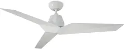
Vortex
works with the
Google Assistant
FR-W1810Vortex Instructions2
Please read and
save these instructions
before installation
DO NOT RETURN TO STORE

FR-W1810
Vortex Instructions 3
For all questions about your ceiling fan please read all included
instructions, installation procedures, troubleshooting guidelines
and warranty information before starting installation.
For missing parts or general inquiries call our trained technical staff at:
1-866-810-6615 option 0
MON-FRI 8AM-8PM EST
Email: customerservice@modernforms.com
Or live chat at modernforms.com
For fast service have the following information below when you call:
1. Model Name and Number
2. Part Number and Part Description
3. Date Of Purchase and Purchase Location
1-866-810-6615 option 1
MON-FRI 8AM-8PM EST
Email: fansupport@modernforms.com
General Inquiries
Fan Support

FR-W1810Vortex Instructions4
For operation, maintenance, and troubleshooting information,
visit http://modernforms.com/fan-support/
To reduce the risk of electric shock, ensure electricity has been turned off at the circuit breaker
before beginning. All wiring must be in accordance with the National Electrical Code “ANSI/NFPA
70” and local electrical codes. Electrical installation should be performed by a licensed electrician.
The fan must be mounted with a minimum of 7 ft. (2.1m) clearance from the trailing edge of
the fan blades to the floor and a minimum of 1.5 ft (0.5m) from the edge of the fan blades to the
surrounding walls. Never place objects in the path of the fan blades. To avoid personal injury or
damage to the fan and other items, please be cautious when working around or cleaning the fan.
To avoid electrical shock or damage to the motor or finish, do not use water or chemicals
when cleaning the fan or fan blades. A dry cloth or lightly dampened cloth will be suitable
for most cleaning.
After making electrical connections, spliced conductors should be turned upward and pushed
carefully up into the outlet box. The wires should be spread apart with the grounded conductor and
the equipment-grounding conductor on one side of the outlet box, and the ungrounded conductor
on the other side of the outlet box.
All set screws must be checked and re-tightened
where necessary before installation.
Safety Rules
FR-W1810
Vortex Instructions 5
WARNING: Do not install or use your fan if any part(s) is/are damaged or missing. This product
is designed for use only with the supplied parts and/or accessories designated for use with this
product by Modern Forms. Substitution of parts or accessories not designated for use with this
product by Modern Forms could result in personal injury or property damage and will void the
warranty. Contact an authorized dealer or the manufacturer if any parts are damaged or missing.
WARNING: To reduce the risk of electric shock, this fan must
be installed and operated with the supplied wall control, or controlled from the Modern Forms app
or Wi-Fi Touch Panel Wall Control (not included).
WARNING: Do not use power tools to assemble or install your fan. Using power tools can result in
improper assembly which can lead to noise or fan damage,personal injury or property damage.
WARNING: To reduce the risk of personal injury, do not bend the blade arms when installing the
brackets, balancing the blades or cleaning the fan.
WARNING: Do not insert foreign objects between rotating fan blades.
WARNING: Do not operate fan unless fan blades are in place. Noise and fan damage can occur
WARNING: This appliance is not intended for use by young children without supervision.
WARNING: To reduce the risk of fire, electric shock, personal injury or damage to the fan or other
items, the outlet box and support structure must be securely mounted and capable of reliably
supporting a minimum of 35 Ibs (15.9 kg). Use only UL/cUL listed outlet boxes marked “FOR FAN
SUPPORT.” Use only the screws and washers provided with the outlet box.
CAUTION: Before assembling your fan, refer to the “Making the Electrical Connections“
section. If you feel you do not have enough wiring knowledge or experience, have your fan
installed by a licensed electrician.
NOTE: Before servicing or cleaning the fan, switch power off at the circuit breaker.
FR-W1810Vortex Instructions6
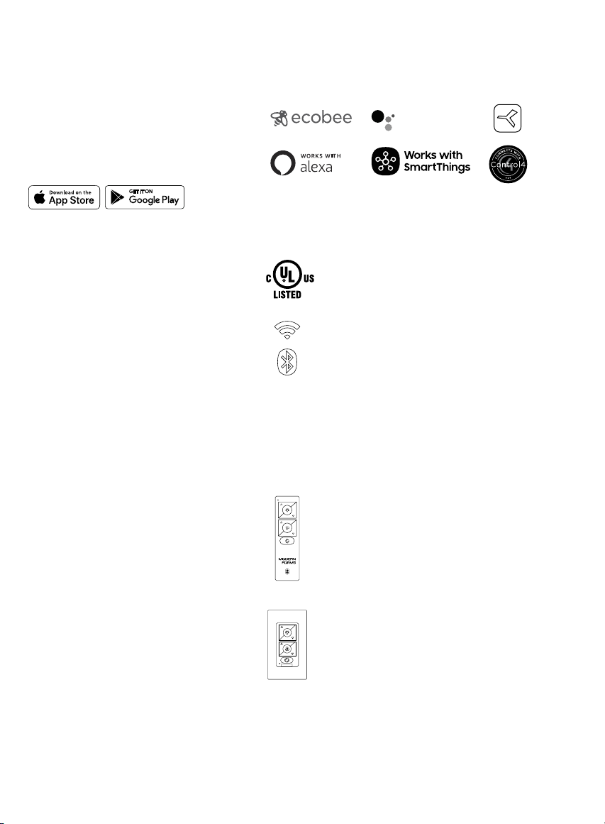
Get Smart...
Integrates
seamlessly with:
devices you already own
works with the
Google Assistant
Premium smart
features:
Accessories:
DC
MOTOR
complement high quality materials
personalize your experience
Quiet, reliable, and up to 70%
more ecient than AC fans
Wi-Fi and Bluetooth enabled
for exible control
Bluetooth Wall Control
Dims light to 1% | ON/OFF
6 fan speeds
F-WCBT-WT White
Bluetooth Remote Control
Dims light to 1% | ON/OFF
6 fan speeds | Sold separately
F-RCBT-WT White
Wet Location-listed to the strictest
UL/cUL safety regulations. Finished
and rated for interior and exterior use
FR-W1810
Vortex Instructions 7
Contents
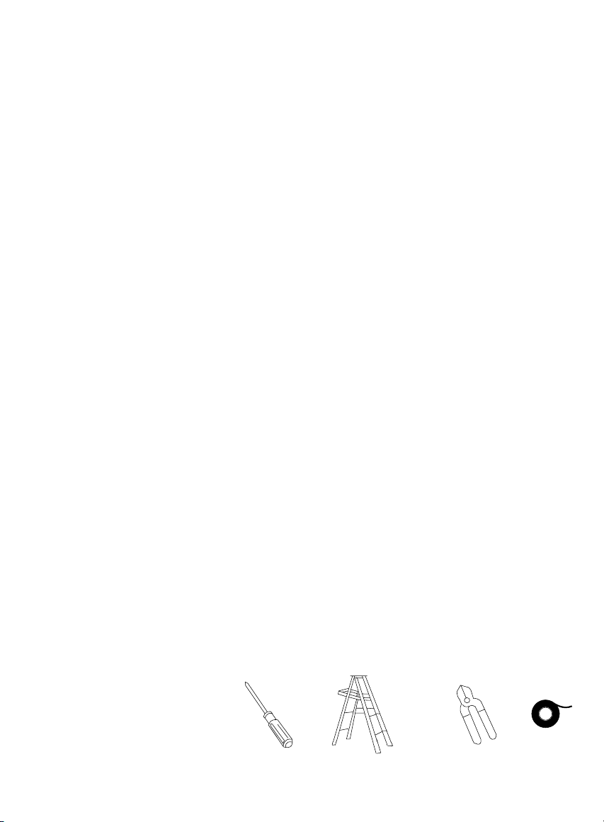
Tools Required
1. Mounting Options 10
2. Hanging the Fan 12-14
3. Making the Electrical Connections 16
4. Installing the Wall Control 18
5. Finishing the Installation 20
6. Attaching the Fan Blades 20
7. Installing the Motor Assembly to Fan Blades 20
8. Controlling the Fan 22
9. Reset 24
10. Breeze Mode 24
11. Application 24
12. Accessories 26
13. Troubleshooting 28-30

FR-W1810Vortex Instructions8
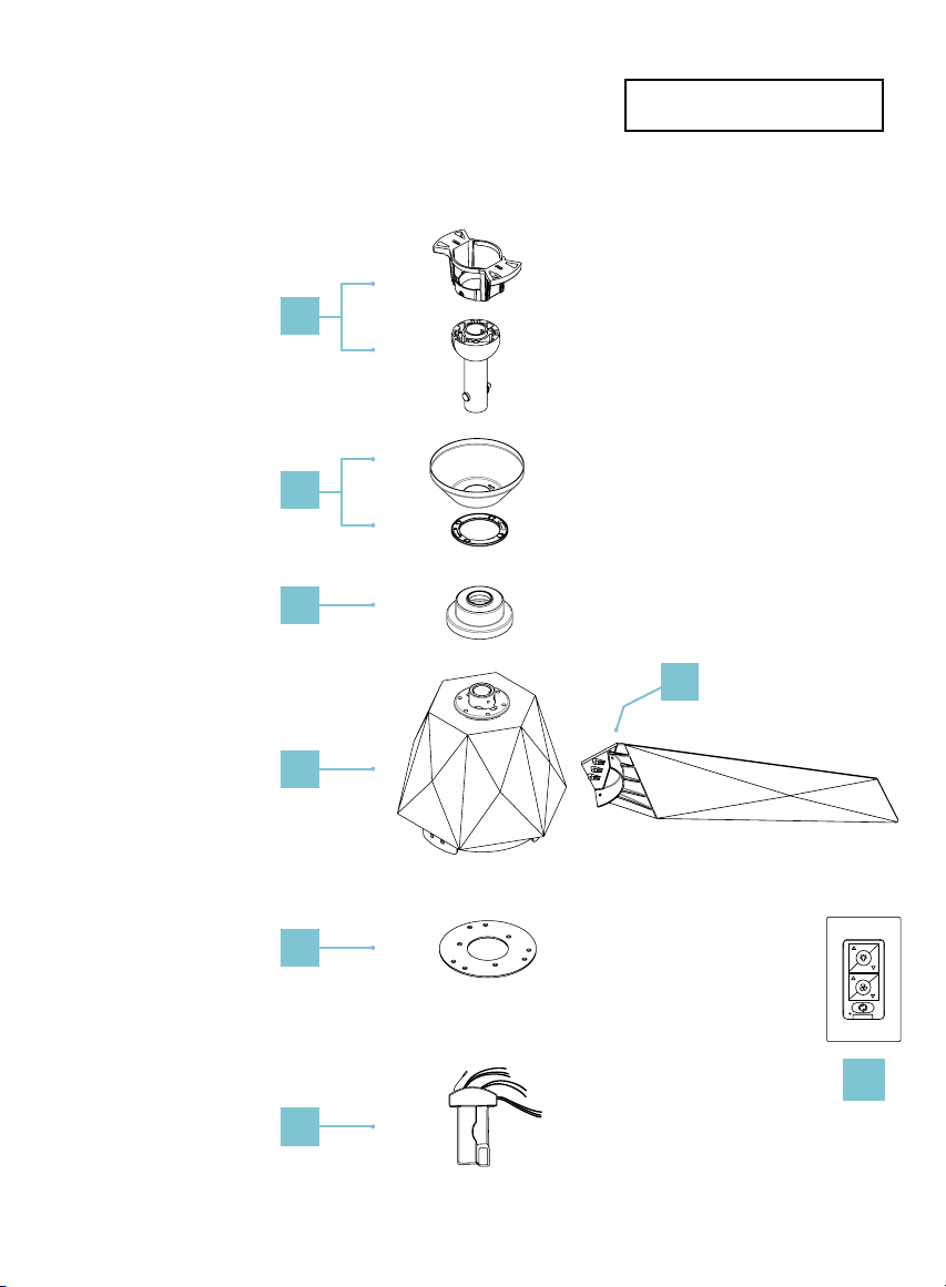
Package Contents
Before discarding packaging materials be certain all parts have been removed.
Place the parts from the hardware bag into a small container to keep them from being lost.
5. Motor Assembly
6. Blade Collector Ring
7. Control Receiver
W/Hardware
F-R3N-1810-060
8. Wall Control W/ Hardware
F-WCBT-WT
1. Blade Set of 3
RPL-F1810-60-BD-***
2. Hanger Assembly
Mounting Bracket
Downrod Assembly
RPL-HGR-ASM-**
3. Canopy W/Trim
Canopy Ring
RPL-CAN-OCT-***
4. Coupling Cover
RPL-COU-CVR-**
** denotes finish code of fan *** denotes blade sweep of fan
** denotes finish code of fan
• 3/16” x 6mm Philips
/Slotted screws (13 pcs)
Blade Collector Ring
• 1/4” x 11mm Philips
w/Slotted flat head screws
(7 pcs) Blade Screws
• 5.2x8.4x1mm Spring washer
(1) Safety Cable
• 6.5x19x2mm Flat washer (1)
Safety Cable
Hardware Bag
RPL-VORTEX-PARTS
• #10x76mm Pan head Philips
Wood screw (1)
Safety Cable
• #10x38mm Pan Head Phillip
Screws (2)
• Ø5*14*1mm Flat Washer (2)
• 3/16” Star Washer (2)
FR-W1810
Vortex Instructions 9
1
8
4
5
7
6
2
3
Hanging Weight: 13 lbs
IMPORTANT: Please make note of
the MAC ID on the receiver and
keep it in a safe place.
MAC ID

FR-W1810Vortex Instructions10
1. Mounting Options
CAUTION: To prevent electrical shock, ensure electricity has been
turned off at the circuit breaker before beginning.
If there isn’t an existing UL/cUL listed outlet box, please refer to the
following instructions. Secure the outlet box directly to the building
structure. Use appropriate fasteners and building materials. The
outlet box and support structure must be able to fully support the
moving weight of the fan (at least 35 lbs/15.9 kg). Do not use plastic
outlet boxes. Use only UL/cUL listed outlet boxes marked
“FOR FAN SUPPORT.”
Secure the outlet box directly to the building structure.
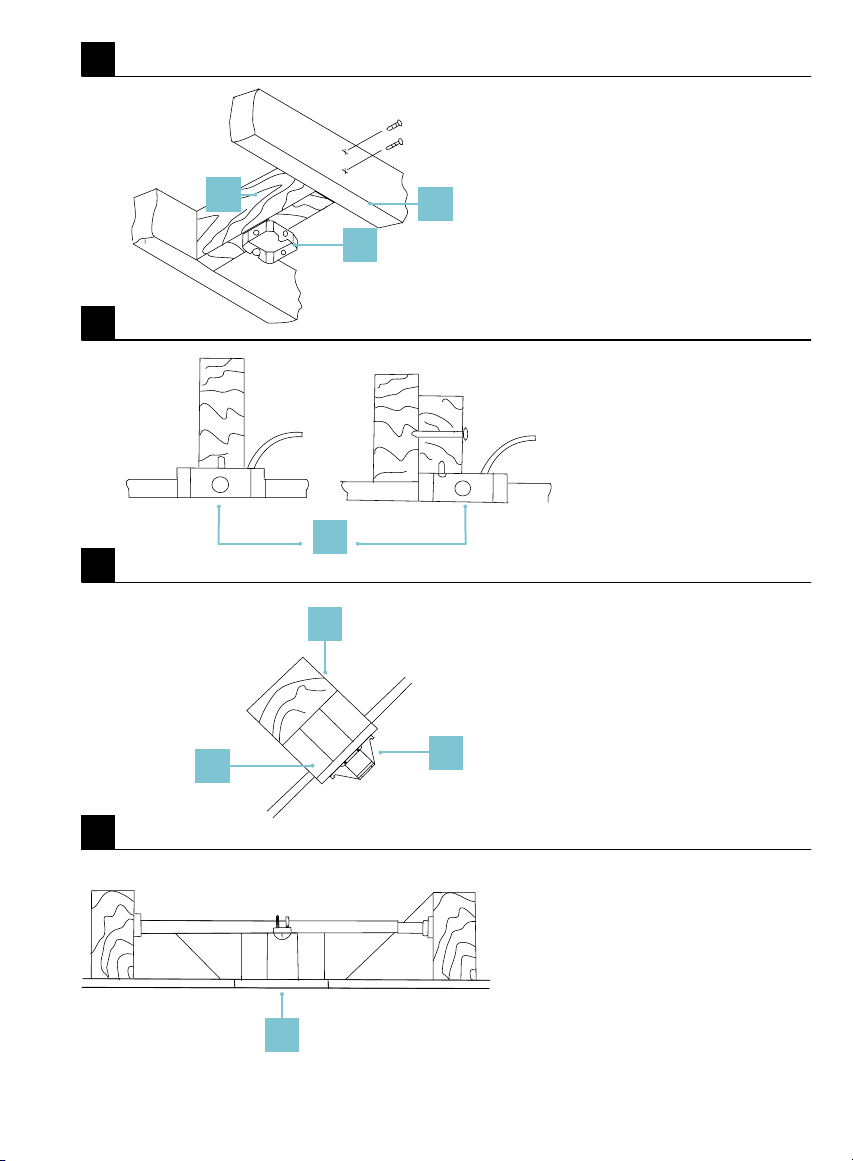
Figures 1-1C are examples of different ways to mount the
outlet box.
NOTE: To hang your fan where there is an existing fixture but no
ceiling joist, you may need an installation hanger bar.
NOTE: Downrod fans can be suspended up to a maximum
recommended length of 72” using additional downrods
(sold separately) and the included 80” lead wire.
NOTE: The sloped ceiling kit (sold separately) is required for sloped
ceiling applications, and will accommodate slopes up to 45° (Fig. 1B).
NOTE: You may need a longer downrod to maintain proper blade
clearance when installing on a steep, sloped ceiling (Fig. 1B).
FR-W1810
Vortex Instructions 11
1
1A
1B
1C
1
1
2
1
1
2
3
3
1. Support Brace
2. Outlet Box
3. Joist
1. Support Brace
2. Mounting Bracket
3. Recess Outlet Box
1. Outlet Box
1. Outlet Box
Support Ceiling
Max 30° Angle
FR-W1810Vortex Instructions12
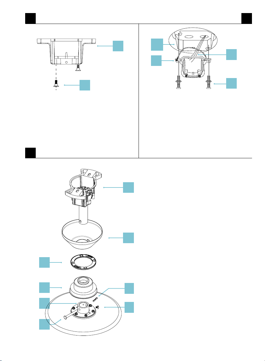
1. Remove 1 of 2 screws from the bottom of mounting bracket and
save for use in section 9. Loosen the other screw (Fig. 2).
2. Pass the 120-volt supply wires through the center hole in the
ceiling mounting bracket as shown in (Fig. 2A).
3. Secure the mounting bracket to the ceiling outlet box with the
screws and washers provided with your outlet box (Fig.2A).
4. Remove the clevis pin and cotter pin and loosen the two collar
screws from the motor collar (Fig. 2B).
5. Feed motor wires through coupling cover, canopy ring,
and canopy.
6. Feed motor wires through downrod assembly.
7. Thread the downrod assembly onto motor collar. Align the holes
of down- rod and collar and insert the cotter pin and clevis pin.
Tighten the two collar screws (Fig. 2B).
WARNING: Failure to properly install the cotter pin
and/or tighten the screws could result in the fan loosening
and possibly falling.
2. Hanging the Fan
Remember to disconnect the power at the circuit breaker.
FR-W1810
Vortex Instructions 13
2 2A
2B
1
2
1. Mounting Bracket
2. Screw
2
1
3
4
1. 120V Wires
2. cUL/UL Listed Electrical Box
3. Mounting Bracket
4. Mounting Screws
(supplied with outlet box)
1
3
9
8
7
5
6
4
1. Hanger Ball/
Mounting Bracket
2. Downrod
3. Canopy
4. Canopy Screw Cover
5. Coupling Cover
6. Collar
7. Cotter Pin
8. Clevis Pin
9. Screws

FR-W1810Vortex Instructions14
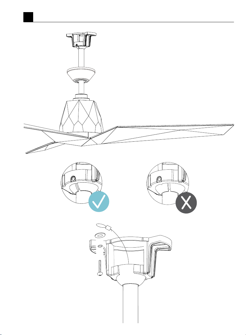
8. Carefully lift the fan motor assembly up to the mounting bracket
and seat the hanger ball in the mounting bracket socket. Make
sure the tab on the mounting bracket socket is properly seated
in the groove in the hanger ball. Rotate the socket assembly until
the ball drops and locks into the hanger bracket screw (Fig. 2C).
9. Secure the safety cable into the structure beams using the wood
screw, washers, and spring washers provided (Fig. 2C).
NOTE: A Safety cable is required for all installations in Canada.
Safety cable is required for ceiling fan and light combinations over
35 lbs. in both flush and downrod models in the United States.
2. Hanging the Fan
Remember to disconnect the power at the circuit breaker.
FR-W1810
Vortex Instructions 15
2C
FR-W1810Vortex Instructions16
3. Making the Electrical Connections
WARNING: Installation of this fan requires that a three-conductor
cable (including ground wire) which should run between ceiling and
wall outlet box.
WARNING: Check to see that all connections are tight, including
ground, and that no bare wire is visible at the wire nuts,
except for the ground wire.
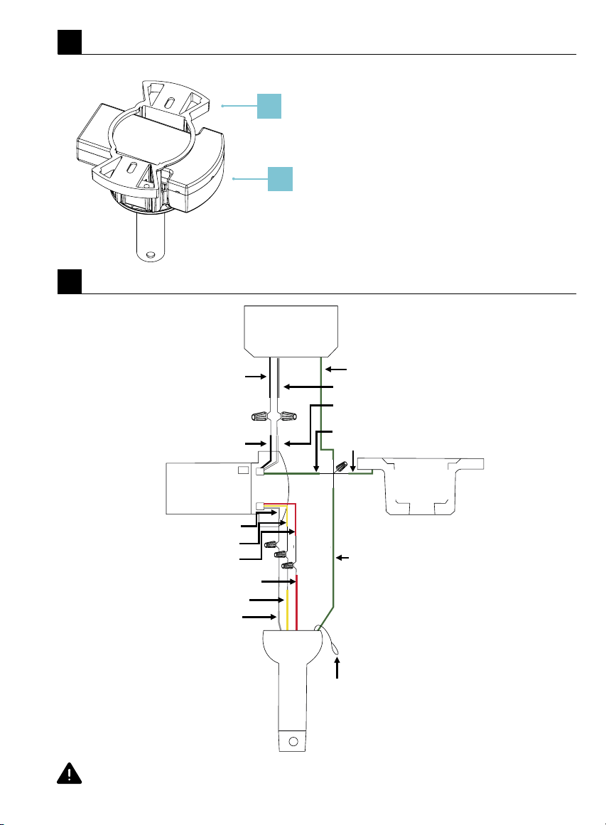
Insert the receiver into the mounting bracket with the flat side of the
receiver facing the ceiling (Fig. 3).
Motor to Receiver & Receiver to house supply wires (Fig. 3A).
1. Connect the hanger ball/downrod assembly ground wire,
mounting bracket ground wire and receiver ground wire to
the ground wire in outlet box.
WARNING: Failure to connect ground wires could result in
poor fan control functionality.
2. Connect the red wire from the fan to the red wire marked
“TO MOTOR” from the receiver.
3. Connect the grey wire from the fan to the grey wire marked
“TO MOTOR” from the receiver.
4. Connect the yellow wire from the fan to the yellow wire marked
“TO MOTOR” from the receiver.
5. Connect the black (hot) wire from the ceiling to the black wire
marked “AC in L” from the receiver.
6. Connect the white (neutral) wire from the ceiling to the white
wire marked “AC in N” from the receiver.
NOTE: Please cap off white wires marked “FOR LIGHT” and blue
wires marked “FOR LIGHT” from receiver with wire nuts and
electrical tape.
NOTE: Please use wire nuts and electrical tape. Failure to make
proper electrical connections may result in damage to the
electronics.
FR-W1810
Vortex Instructions 17
Follow the steps above to connect the fan to your household wiring. Use the plastic wire nuts with your fan.
Secure the plastic wire nuts with electrical tape. Make sure there are no loose strands or connections.
3
3A
1. Mounting Bracket
2. Receiver
Black(Hot)
can be RED from Switch leg
Black(Line in H)
RED(to Motor)
GREEN(Ground)
GREEN(GND Must Use)
GREEN(Hanger Bracket Ground)
GREEN(Hanger Bracket Ground)
RED(to Motor)
GREY(to Motor)
WHITE(Neutral)
Safety Cable
GREY(to Motor)
YELLOW(to Motor)
WHITE(Line in N)
YELLOW(to Motor)
Outlet
Box
Receiver
Hanger Ball & Downrod
Hanger
Bracket
1
2
FR-W1810Vortex Instructions18
4. Installing the Wall Control
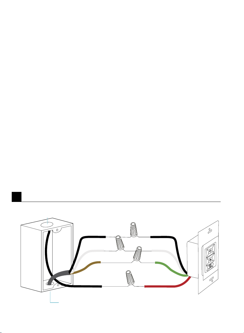
1. Connect the green wire marked “GROUND” from the wall
control to the copper wire from the wall outlet box that
feeds back to the circuit breaker – important for proper
fan function (Fig. 4).
2. Connect the black wire marked “LINE IN” from the wall control to
the black LINE VOLTAGE wire from the wall outlet box that feeds
back to the circuit breaker (Fig. 4).
3. Connect the red wire from the wall control to the black wire from
the wall outlet box that feeds up to the fan (Fig. 4).
4. Connect the white wire from the wall control to the white
(neutral) wire from the wall outlet box (Fig. 4).
5. Carefully tuck the wire connections inside the outlet box.
Secure the wall control with the two (2) wall control screws
provided (Fig. 7A).
6. Attach the wall mounting plate over the wall switch and secure
with the two (2) wall mounting plate screws provided (Fig. 4A).
7. Fasten the wall plate to the wall mounting plate (Fig. 4A).
4
Wall Switch WiresHouse Wires
(Hot In)
(Neutral)
(Ground)
(Hot out to Fan)Fan Switch leg
(Copper/Ground)
(Neutral)
(Hot)
From Breaker
* Home Wiring may vary
to Fan
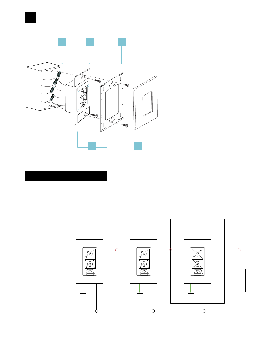
FR-W1810
Vortex Instructions 19
4A
Multi-location wiring
1 2 3
54
1. Wall Outlet
2. Wall Control
3. Wall Mounting Plate
4. Mounting Plate Screws
5. Wallplate
Individually pair each of the wall controls with the fan
receiver using the pairing instruction. See page 22.
Line/Hot
Red
Green (Green or Bare)
Wall Control 1 Wall Control 2 Wall Control 3
If Applicable
FAN
Neutral/White
FR-W1810Vortex Instructions20
6. Attaching the Fan Blades
1. Assemble the three blades together using the blade collector
ring and the screws provided (Figs. 6 & 6A).
7. Installing the Motor Assembly to Fan Blades
1. Attach blade assembly to the motor assembly as shown with
provided blade screws (Fig. 7).
5. Finishing the Installation
1. Secure all wire connections with supplied wire ties to assist in
canopy installation.
2. Tuck connections neatly into ceiling outlet box.
3. Slide the canopy up to hanger bracket and place the key hole on
the canopy over the screw on the hanger bracket. Turn canopy
until it locks in place at the narrow section of the key holes.
4. Align the circular hole on canopy with the remaining hole on the
hanger bracket. Secure by tightening the one screw previously
loosened and the one previously removed. Adjust the canopy
screws as necessary until the canopy and canopy cover are snug.
5. Adjust the canopy screws as necessary until the canopy
and canopy screw ring are snug.
WARNING: Make sure tab at bottom of hanger bracket is
properly seated in groove of hanger ball before attaching canopy to
bracket. Failure to properly seat tab in groove could cause damage to
electrical wiring.
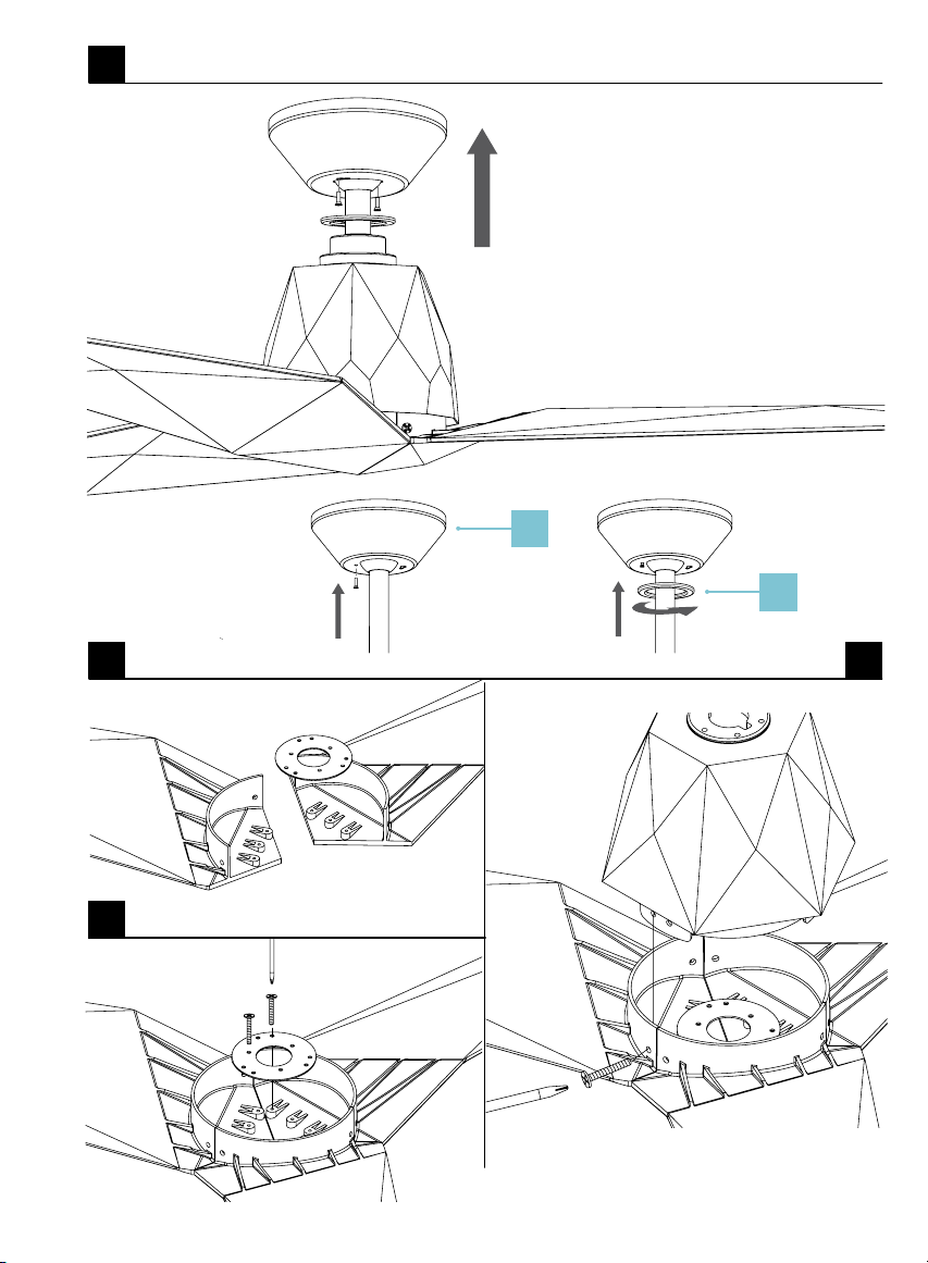
FR-W1810
Vortex Instructions 21
6
7
6A
5
1. Canopy
2. Canopy Ring
1
2

FR-W1810Vortex Instructions22
8. Controlling the Fan
Your fan was delivered to you with the included control already paired
to your fan.
A: Light On/Off, Bright/Dim
B: Fan On/Off, Speed Up/Down
C: Season (Summer/Winter)
Air-Gap Switch: Pull tab to power off in case of emergency. Not
necessary for normal fan operation (only included with wall control).
NOTE: Your fan features 6 speeds. An audible tone will indicate when
the speed is increased or decreased. When the fan has reached the
minimum/maximum speed level the fan will beep twice.
Controlling One or Multiple Fans with Remote or Wall Controls
The Bluetooth Remote or Wall Control is capable of controlling
an unlimited number of fans within line of site.
See (Fig. 8C) for Pairing.
NOTE: Pairing must be completed within three (3) minutes of
powering the fan.
Synchronizing Control Across Multiple Fans
If you are controlling multiple fans with one controller, fans/lights
may be synced by referring to Fig. 8B and instructions on the next page.
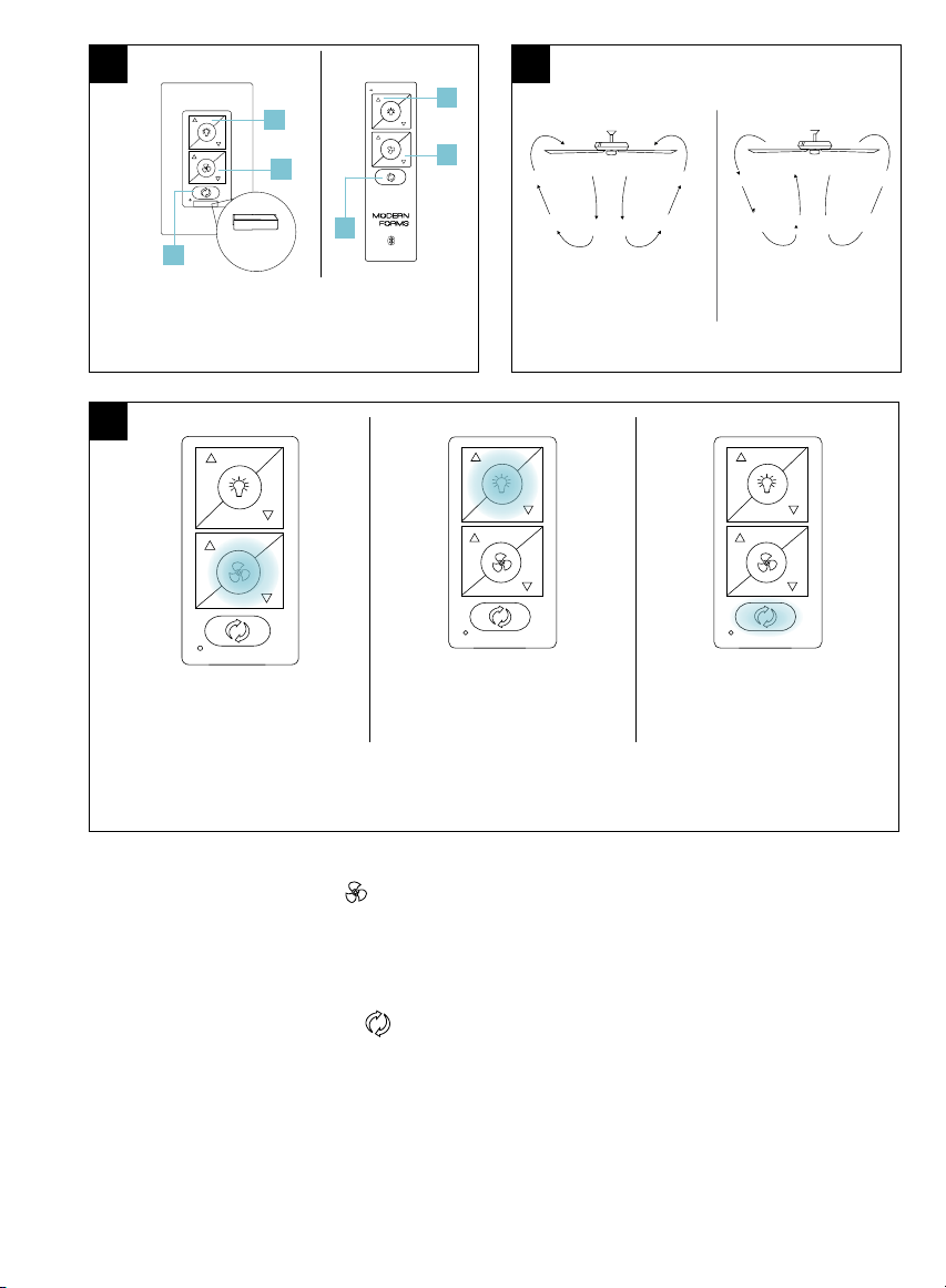
FR-W1810
Vortex Instructions 23
A
B
C
Air-Gap
Switch*
Wall Control
* Air-Gap Switch only included
with wall control
Remote
Control
8
8A
Summer Mode
(Counter-Clockwise)
Winter Mode
(Clockwise)
Fan On/Off
Press and hold
button for 4 seconds.
Light On/Off
Press and hold
button for 4 seconds.
Fan Direction
Press and hold
button for 4 seconds.
8B
Fan On/Off: Press and hold button for 4 seconds. The LED on the remote will flash
green and all connected fans will beep to indicate the message has been received. All
fans will turn off. This will bring all fans controlled by the remote into sync.
.
Fan Direction: Press and hold button for 4 seconds. The LED on the remote will
flash green and all connected fans will beep to indicate the message has been
received. All fans will be set to summer mode (CCW rotation). This will bring all fans
controlled by the remote into sync.
A
C
B
FR-W1810Vortex Instructions24
9. Reset
11. Application
10. Breeze Mode
In addition to the included wall control, you can control your fan with a remote
control (sold separately) or through the Modern Forms app. To use the Modern Forms
app, download it for free from the App Store or Google Play.
1. Open the app to create your account. You can also log in using your
Facebook or Google account.
2. To set up a Wi-Fi connection you will need the SSID and Wi-Fi password for the
network you wish to connect to.
3. You will receive a prompt to name your fan device and upload an optional picture
of it if you choose.
4. The Modern Forms app allows you to perform normal fan functions, as well
as create schedules, set sleep timers, invite other users, create groups, and
use smart features such as Adaptive Learning. Integrate with smart home
systems you already own including Amazon Alexa, Google Assistant, Samsung
SmartThings, Control 4, and more.
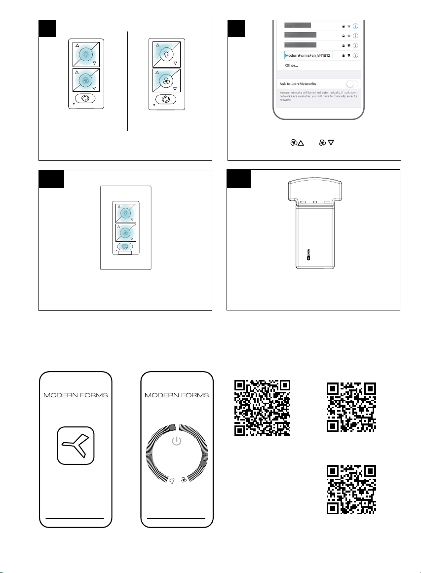
If advised by fan support, you can reset your fan to factory settings
by referring to (Fig. 10A) or (Fig. 10B).
NOTE: If you change your Wi-Fi settings (SSID or Security
Passphrase) you will require a Wi-Fi reset. Refer to Fig. 10 and then
use the Modern Forms app to connect your fan to the new network.
Breeze Mode mimics the natural ebb and flow of winds in nature by
varying the fan speed.
NOTE: Breeze Mode always rotates your fan in the Summer direction.
1. To start Breeze Mode, press and for 4 seconds. The LED will
blink green and the fan will beep.
2. To exit Breeze Mode and return to standard fan mode, press
and for 4 seconds. The led will blink green and the fan will
beep. Your fan will return to the direction and speed it was set to
prior to entering Breeze Mode.
FR-W1810
Vortex Instructions 25
For detailed
Instructions
and Smart
Home Device
Integration
Scan and follow prompts for multilingual
instruction options and Smart Fan FAQs:
Spanish
French
10% LV2
8C
Pairing
Press and hold buttons
for 10-15 seconds.
9A
9
9B
Unpairing
To purge, press and hold
buttons for 4 seconds.
Fan Wi-Fi Reset
Press and hold the and for 10 seconds until
LED blinks green and receiver emits 2 long beeps
Factory Reset
Press and hold buttons for 10 seconds until the
fan emits 3 beeps indicating the reset
FR-W1810Vortex Instructions26
12. Accessories
personalize your experience
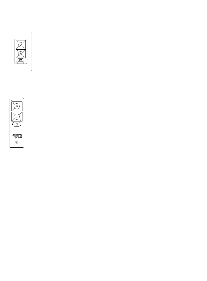
Bluetooth Wall Control
Dims light to 1% | ON/OFF
6 fan speeds
F-WCBT-WT White
Bluetooth Remote Control
Dims light to 1% | ON/OFF
6 fan speeds | Sold separately
F-RCBT-WT White
FR-W1810
Vortex Instructions 27
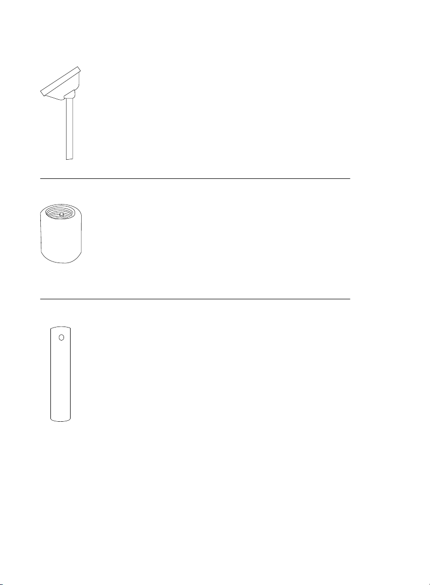
Coupler
Connects two downrods
XF-I
Sloped Ceiling Kit
Designed to accommodate buildings with steeper
sloped ceilings up to 45° or 12/12 pitch
XF-SCK
Downrod
XF-12 - 12” Downrod | XF-18 - 18” Downrod
XF-24 - 24” Downrod | XF-36 - 36” Downrod
XF-48 - 48” Downrod | XF-60 - 60” Downrod
XF-72 - 72” Downrod

FR-W1810Vortex Instructions28
13. Troubleshooting
My Fan Will Not Start
1. Check main and branch circuit fuses or circuit breakers.
2. Check line wire connections to fan and switch wire connections in
the switch housings.
CAUTION: Make sure the main power is turned off!
My Fan is Noisy
1. Allow for 24-hour break-in period. Most noises associated with a
new fan will go away during this time period.
2. Check to make sure the screws which attached to the blades
(and blade arms when applicable) are tight.
3. Check to make sure all screws in motor housing are snug.
4. Make sure light cover is tightened and/or glass is snug.
5. Tighten the hanger bracket screws and make sure the outlet box
is secured.
6. Your wire connectors may be rattling against the fan’s canopy.
7. Make sure you have a cUL/UL approved outlet box and it is
installed correctly.
My Fan is Wobbling
1. Tighten the setscrews in the downrod.
2. Make sure your hanger ball assembly is locked into place in the
hanger bracket.
3. Tighten the hanger bracket screws to the outlet box.
4. Make sure the fan blades are properly aligned and securely
fastened to the motor housing assembly/blade arms.
5. Make sure the gaps between the blades are evenly distributed or
make sure you are using an approved cUL/UL listed outlet box
and it is installed correctly.
FR-W1810
Vortex Instructions 29
My Fan is not producing Enough Air Movement
If possible, please consider using a longer than included downrod.
My remote or wall control is not controlling my fan
Verify that the fan is receiving power by power cycling the fan.
To do this:
1. Cut power to the fan via standard On/Off wall switch, or the
breaker if standard wall switch is not applicable.
2. Wait at least 10 seconds, and then restore power.
3. The fan will power on in Pairing mode for 3 minutes.
4. Press and hold and buttons on wall control for
10-15 seconds.
5. When the LED indicator remains solid green, and three (2)
audible beeps are heard, the pairing process is complete.
I don’t see my fan’s WiFi (ModernFormFan_XXXXXX) in my phone’s
list of available WiFi networks.
1. If your fan had been previously paired the Wi-Fi radio will be off.
2. To turn on Wi-Fi, press and hold fan speed up and fan speed down
buttons on your remote control or wall control for 6 seconds.
3. The fan will beep and you will see its Wi-Fi network available for
connection.
My home Wi-Fi network is not showing up in the app’s list
during setup.
1. Your fan supports connection with 2.4GHz 802.11b/g/n networks.
Confirm your network is compatible by checking your router
settings or contact your router manufacturer.
2. Make sure your network’s SSID is not hidden.
3. Your fan does not support 5 GHz network connectivity.
connection.

FR-W1810Vortex Instructions30
13. Troubleshooting cont.
My Fan failed to join the Wi-Fi network
1. Make sure you entered the correct Wi-Fi password and your
mobile device is connected to the same network you attempted
to connect the fan.
2. Make sure you are within the router manufacturer’s specified
range. If all of these steps have failed - please power cycle your
fan and router and retry.
What is power cycling and how do I power cycle my fan?
Power cycling is the act of temporaily removing the power source for
your fan. If the fan is powered through a wall switch, turn the switch
off for 10 seconds and back on. Alternately, you can use the circuit
breaker the fan is connected to by toggling it off for 10 seconds and
back on. If your fan is wired through a Modern Forms wall control
(P/N: F-WCBT-WT) pull the Air-Gap Switch on your wall control, wait
10 seconds, and re-insert.
What is Adaptive Learning?
Adaptive learning is an exclusive feature that allows your fan to learn
your daily/weekly habits and automatically recommend scheduled
activity through the Modern Forms app. This feature can be toggled
on or off.
What is Breeze Mode?
Breeze Mode mimics the natural ebb and flow of winds in nature by
fluctuating your fan’s speed.

FR-W1810
Vortex Instructions 31
What is Pairing?
Pairing is the process of connecting your Modern Forms remote or
wall control to your fan. Your fan comes pre-paired to your included
remote control. However, if you want additional controls for your
fan or if you’re replacing a control, refer to the pairing and unpairing
section of the instructions.
What is a Factory Reset?
Factory Reset is a restore of the fans original settings. This can
be achieved from the control or by pressing and holding the small
button on the receiver until you hear three audible beeps or by
holding down the fan toggle, light toggle, and season toggle buttons
on your paired remote or wall control for 10 seconds.
NOTE: You will need to re-pair your remote or wall controls to the
fan following a factory reset. A factory reset will also disconnect the
fan from your home Wi-Fi network and will require you to add the fan
using the Modern Forms Smart Fans app.
Please refer to the FAQ section of our app for further guidance.
For all other questions, please contact our dedicated Fan Support
specialists. Contact information can be found at the front of the
instructions.

FR-W1810Vortex Instructions32
Congratulations on your new purchase.
Your new Modern Forms Smart Fan is engineered to make life easier every day. Modern Forms creates future-forward
fans and luminaires that provide energy savings and outstanding efficiency. Our dedication to doing things the right
way goes beyond our love for amazing products. Modern Forms Smart Fans™ warrants any of its outdoor rated
ceiling fan products that they are to be free from defects in material and workmanship for a period of one (1) year
from the date of purchase; outdoor painted finishes are warranted for two (2) years; LED light modules and electronic
components are warranted for five (5) years; DC motors and stainless steel finishes are warranted for lifetime under
normal use to the first non-dealer purchaser.
Although Modern Forms uses the best available materials and does extensive testing for finish endurance, some
fading or chalking may occur and is considered normal. For coastal locations, some corrosion and/or deterioration is
considered “normal wear” in this environment. Therefore, any finish claim due to coastal environment conditions is
not applicable to our warranty. If a product is defective, all efforts will be made to correct the problem in the field. If the
problem cannot be resolved, an RGA number will be issued. Modern Forms obligation is expressly limited to repair or
replacement, without charge, at the Modern Forms factory after prior written return authorization has been granted.
Modern Forms obligation under this warranty shall not extend beyond the distributor’s initial purchase price of the
product and accordingly any consequential damages or labor costs arising out of a defect are expressly excluded. This
warranty shall not apply to products that have been altered, improperly installed, mishandled or misused. Notice of
a defect in writing must be received by Modern Forms within five (5) years from the date of purchase (or according
period of time as outlined by material). Excluded from warranty are any 3rd party component which carries its own
manufacturer’s warranty. Note: Modern Forms product warranty applies only to purchases from authorized Modern
Forms distributors. THERE ARE NO WARRANTIES WHICH EXTEND BEYOND THE DESCRIPTION ON THE FACE HEREOF
INCLUDING WARRANTIES OF MERCHANTABILITY AND FITNESS FOR A PARTICULAR PURPOSE. The Bluetooth ® word
mark and logos are registered trademarks owned by Bluetooth SIG, Inc. and any use of such marks by Wangs Alliance
Corporation is under license. Other trademarks and trade names are those of their respective owners.
Felicidades por tu nueva compra.
Su nuevo ventilador moderno de formas modernas está diseñado para facilitarle la vida cada día. Modern Forms
crea ventiladores y luminarias para el futuro que proporcionan ahorros de energía y eficiencia excepcional. Nuestra
dedicación a hacer las cosas de la manera correcta va más allá de nuestro amor por los productos asombrosos. Modern
Forms garantiza a cualquiera de sus productos para ventiladores de techo con clasificación exterior que estén libres de
defectos en materiales y mano de obra por un período de un (1) año desde el fecha de compra; Los módulos de luz LED
están garantizados por cinco (5) años; Los motores de CC y los acabados de acero inoxidable están garantizados de
por vida bajo el uso normal para el primer comprador no distribuidor.
Aunque Modern Forms utiliza los mejores materiales disponibles y realiza pruebas exhaustivas para la resistencia del
acabado, puede producirse cierto desvanecimiento o parloteo y se considera normal. Para las ubicaciones costeras,
cierta corrosión y / o deterioro se considera “desgaste normal” en este entorno. Por lo tanto, cualquier reclamación de
acabado debido a las condiciones del entorno costero no se aplica a nuestra garantía. Si un producto es defectuoso,
se harán todos los esfuerzos para corregirlo. El problema en el campo. Si el problema no se puede resolver, se emitirá
un número RGA. La obligación de Modern Forms se limita expresamente a la reparación o el reemplazo, sin cargo,
en la fábrica de Modern Forms después de que se haya otorgado una autorización previa por escrito.La obligación
de Formas modernas bajo esta garantía no se extenderá más allá del precio de compra inicial del producto por
Certificate of Warranty

FR-W1810
Vortex Instructions 33
Félicitations pour votre nouvel achat.
Votre nouveau ventilateur intelligent Modern Forms est conçu pour vous simplifier la vie au quotidien. Modern Forms
crée des ventilateurs et des luminaires d’avant-garde qui permettent des économies d’énergie et une efficacité
exceptionnelle. Notre engagement à bien faire les choses va au-delà de notre amour pour les produits étonnants.
Modern Forms garantit à tous ses produits pour ventilateurs de plafond pour extérieur qu’ils ne doivent présenter
aucun défaut de matériau ou de fabrication pendant un (1) an date d’achat; Les modules d’éclairage à LED sont
garantis pendant cinq (5) ans; Les moteurs à courant continu et les finis en acier inoxydable sont garantis à vie dans les
conditions normales d’utilisation par le premier acheteur non revendeur.
Bien que Modern Forms utilise les meilleurs matériaux disponibles et effectue des tests approfondis pour l’endurance
de la finition, des décolorations ou des craies peuvent se produire et sont considérés comme normaux. Pour les
zones côtières, une certaine corrosion et / ou détérioration est considérée comme une «usure normale» dans cet
environnement. Par conséquent, toute réclamation liée à la finition en raison des conditions de l’environnement côtier
ne s’applique pas à notre garantie. Si un produit est défectueux, tous les efforts seront déployés pour y remédier. Le
problème sur le terrain. Si le problème ne peut pas être résolu, un numéro RGA sera attribué. L’obligation de Modern
Forms est expressément limitée à la réparation ou au remplacement, sans frais, dans l’usine de Modern Forms après
autorisation écrite préalable du retour. L’obligation de Modern Forms au titre de cette garantie ne s’étendra pas
au-delà du prix d’achat initial du produit par le distributeur. En conséquence, tout dommage indirect ou tout coût de
main-d’œuvre résultant d’un défaut est expressément exclu. Cette garantie ne s’applique pas aux produits modifiés,
mal installés, manipulés ou utilisés de manière inappropriée. Modern Forms doit recevoir un avis écrit du défaut dans
un délai de cinq (5) ans à compter de la date d’achat (ou selon la période précisée dans les informations fournies).
Sont exclus de la garantie tout composant tiers bénéficiant de la garantie du fabricant. Remarque: la garantie des
produits Modern Forms ne s’applique qu’aux achats auprès des distributeurs agréés Modern Forms. IL N’Y A AUCUNE
GARANTIE QUI ALLAIT AU-DELÀ DE LA DESCRIPTION FACE AU PRESENT, INCLUANT LES GARANTIES DE QUALITÉ
MARCHANDE ET D’ADÉQUATION À UN USAGE PARTICULIER. La marque et les logos Bluetooth ® sont des marques
déposées appartenant à Bluetooth SIG, Inc. et toute utilisation de ces marques par Wangs Alliance Corporation est
sous licence. Les autres marques et noms commerciaux appartiennent à leurs propriétaires respectifs.
parte del distribuidor y, en consecuencia, cualquier daño consecuencial o costo de mano de obra que surja de un
defecto se excluye expresamente. Esta garantía no se aplicará a los productos que hayan sido alterados, instalados
incorrectamente, mal manejados o mal utilizados. La notificación de un defecto por escrito debe ser recibida por
Modern Forms dentro de los cinco (5) años a partir de la fecha de compra (o según el período de tiempo indicado
en el material). Quedan excluidos de la garantía todos los componentes de terceros que tengan la garantía de su
propio fabricante. Nota: la garantía del producto Modern Forms se aplica solo a las compras de los distribuidores
autorizados de Modern Forms. NO HAY GARANTÍAS QUE SE EXTIENDAN MÁS ALLÁ DE LA DESCRIPCIÓN DE SU
CARACTERÍSTICA, INCLUIDAS LAS GARANTÍAS DE COMERCIABILIDAD Y ADECUACIÓN PARA UN PROPÓSITO
PARTICULAR. La marca denominativa y los logotipos Bluetooth ® son marcas registradas propiedad de Bluetooth SIG,
Inc. y cualquier uso de dichas marcas por parte de Wangs Alliance Corporation se realiza bajo licencia. Otras marcas
comerciales y nombres comerciales pertenecen a sus respectivos propietarios.

FR-W1810Vortex Instructions34

FR-W1810
Vortex Instructions 35
modernforms.com
FR-W1810