REPLACING THE BATTERY
TROUBLE SHOOTING
If light doesn’t turn on, check the
battery to ensure that it is making
secure contact with the terminals.
If this doesn’t work, replace with a
new battery.
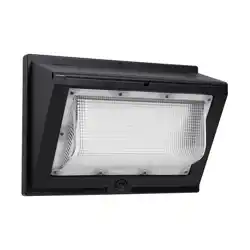
4000 Lumen Solar LED Wall Pack Light
Model No.
RMWP04001H-06S
WARNING: Do not dispose of lithium batteries in municipal waste stream or by fire as batteries may explode. Do not open, short circuit, or destroy batteries. Dispose of batteries in
accordance with Local, State, and Federal regulations. Do not mix old and new batteries. Do not mix alkaline, standard (carbon-zinc), or rechargeable (nickel cadmium, nickel metal
hydride or lithium ion) batteries.
INSTRUCTIONS
Required Tools
Phillips-head
Screwdriver
Pencil
Electric drill
drill bit size:
ø7.5mm (3/10 in.)
INSTALLATION
FOR FIRST-TIME USE: SOLAR LIGHT NEEDS TO CHARGE IN FULL SUNLIGHT FOR 8 -12 HOURS WITH THE SWITCH IN THE
“ON” POSITION TO FULLY CHARGE THE BATTERY.
Hardware Included
Parts
(B) Wall Anchor X 2(A) Screw X 2
(C) Light Fixture X 1
OPERATION
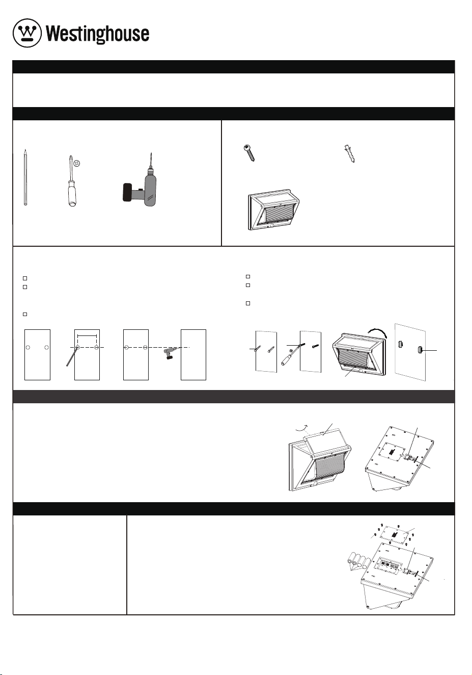
Drill two holes.
1
Marking the location
Measure the width of two holes on the back of the light
to align holes for the 2 screws (Part A) on the surface.
The distance between the two holes is 8.66 in. (220 mm).
Mark the location where you want to mount the light fixture (Part C).
2
Mounting the light fixture
Insert the wall anchors (Part B) so they are flush with the surface.
Insert the screws (Part A) and leave at least 1/4 in. (6.3 mm) of the
screws (Part A) outside of the surface for holding the light.
Mount the light (Part C) on the screws (Part A) by placing the
keyholes on the back of the light over the screw heads.
B
x
x
8.66in. (220mm)
A
C
A
Adjust the solar panel to be in direct sunlight for 8-12 hours to fully charge the light.
Slide the light power switch to the “ON” position, the light will turn on automatically at
night, when motion is detected. Slide the CCT switch to select the color temperature
(3000K, 4000K or 5000K).
NOTE: Light delivers up to 4000 lumens on a full charge. Standby mode 100 lumens.
Motion sensor detection distance up to 26.2 ft (8m). Motion sensor detection angle
up to 120 degrees.
NOTE: Avoid aiming the control at:
Objects that change temperature rapidly to prevent false triggering, such as heating
vents and air conditioners. Moving objects such as trees and street trac.
Solar Panel
Power Switch
CCT Switch
Slide the power switch to the "OFF" position. Use a Phillips head
screwdriver to remove the 8 screws holding the battery cover
in place. Replace old batteries with 4 new 3.7V, 2000 mAh
lithium (18650) rechargeable batteries. Replace the battery
cover by aligning it properly and replacing the 8 screws
removed earlier. Slide the power switch to the “ON” position.
For optimal performance, allow the light fixture to charge in
full sunlight for 8-12 hours, to fully charge the battery.
Battery Cover
Screws
Batteries
Power Switch
CCT Switch

1. During the one-year warranty period, we provide services including refund or replacement without charge to those who
use the device in accordance with the user manual.
2.This warranty does not cover:
(A) Failure or damage due to the improper use, repair or remodeling.
(B) Failure or damage because of falling.
(C) Failure or damage caused by fire, earthquake, flood, lightning and other natural disasters.
(D) Failure or damage when used other than its intended use.
(E) Failure or damage caused by the third-party products other than this device.
If you have questions or need assistance, please email Support@solarlights.Westinghouse.com or call customer service
at 1-888-445-8974.
DO NOT RETURN THIS PRODUCT TO THE STORE
and Westinghouse are trademarks of Westinghouse Electric Corporation. Used under license by Rayman Lights, Inc.
All Rights Reserved.
To ensure full warranty coverage, this product must be purchased from an authorized retailer. Purchases made through
unauthorized third-party sellers will void all warranty protections. This includes eligibility for product replacements,
repairs, or customer support. Please retain your proof of purchase from an authorized source.
FCC WARNING
This device complies with Part 15 of the FCC Rules. Operation is subject to the following two conditions: (1) this device may
not cause harmful interference, and (2) this device must accept any interference received, including interference that may
cause undesired operation.
WARNING: Changes or modifications to this unit not expressly approved by the party responsible for compliance could
void the user’s authority to operate the equipment.
NOTES: This equipment has been tested and found to comply with the limits for a Class B digital device, pursuant to Part 15
of the FCC Rules. These limits are designed to provide reasonable protection against harmful interference in a residential
installation. This equipment generates, uses and can radiate radio frequency energy, and if not installed and used in
accordance with the instructions, may cause harmful interference to radio communications. However, there is no
guarantee that interference will not occur in a particular installation. If this equipment does cause harmful interference to
radio or television reception, which can be determined by turning the equipment o and on, the user is encouraged to try
to correct the interference by one or more of the following measures:
• Reorient or relocate the receiving antenna.
• Increase the separation between the equipment and receiver.
• Connect the equipment into an outlet on a circuit dierent from that to which the receiver is connected.
• Consult the dealer or an experienced radio/TV technician for help.
Company Name: Rayman Lights Inc.
Company Address: 2020 Firedancer Ln, Bear, DE 19701, USA
Telephone Number: 1-888-445-8974
LIMITED WARRANTY