Service Manual_
1
Service Manual
HUS-248INBM - BMF No Frost Series
Market Model
Product Model
Product Code
HD-332RWEN.BI
CE-BCD255WX-JT
22031020012223
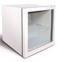
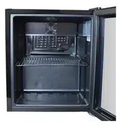
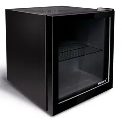
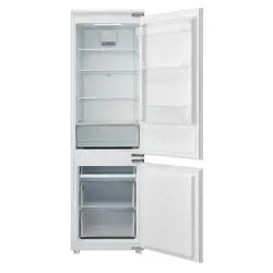
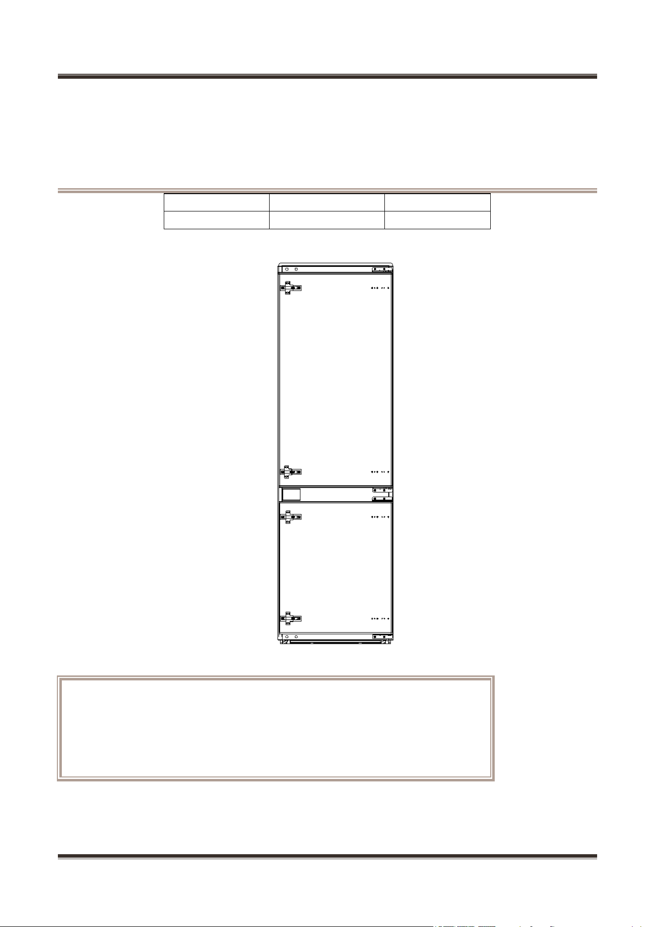
The picture in this service manual is only for reference, and specific appearance
and configuration are subject to the real product.
This manual mainly teaches the method, the specific work skill needs engineer to
accumulate through the daily work.
Service Manual_
2
WARNING
Important Safety Notice
There are special components used in this equipment which are important for safety. These parts are
marked by in the Schematic Diagrams, Circuit Board Diagrams, Exploded Views and Replacement
Parts List. It is essential that these critical parts should be replaced with manufacturer’s specified parts to
prevent shock, fire or other hazards. Do not modify the original design without permission of manufacturer.
WARNING
Important Safety Notice
The Maintenance Manual is only for the use of maintenance personnel with certain experience and
background in electrical, electronic and mechanical field.
Any attempt to repair main devices may lead to personal injury and property loss.
Manufacturers or distributors are not responsible for the content of the Manual and interpretation thereof.

Service Manual_
3
Contents
1. 1. SIGNIFICANT UPDATE NOTES ...................................................................................................................5
2. SAFETY WARNING CODE ....................................................................................................................................6
2.1 WARNING FOR OPERATION SAFETY ........................................................................................................................... 6
2.2 SAFETY INSTRUCTION FOR REFRIGERANT ................................................................................................................. 8
3. INSTALLATION AND COMMISSIONING .............................................................................................................9
3.1 HANDLING ................................................................................................................................................................... 9
3.2 DOOR DISASSEMBLY AND ASSEMBLY ........................................................................................................................ 9
3.3 INSTALLATION LOCATION ............................................................................................................................................ 9
3.4 LEVELING OF THE REFRIGERATOR ........................................................................................................................... 12
3.5 LEFT OR RIGHT OPEN DOOR REVERSAL ................................................................................................................... 13
4. MAIN PARTS AND EXTERNAL DIMENSION .................................................................................................... 16
4.1 MAIN PARTS .............................................................................................................................................................. 16
4.2 EXTERNAL DIMENSION.............................................................................................................................................. 17
4.3 MIDEA PRODUCT SERIAL NUMBER AND LOCATION ................................................................................................... 17
5. ELECTRIC CONTROL SYSTEM ......................................................................................................................... 19
5.1 ELECTRICAL PARAMETERS ....................................................................................................................................... 19
5.2 CIRCUIT DIAGRAM .................................................................................................................................................... 20
5.3 WIRING DIAGRAM ..................................................................................................................................................... 21
6. REFRIGERATION SYSTEM ................................................................................................................................ 22
6.1 REFRIGERATING PIPING SYSTEM.............................................................................................................................. 22
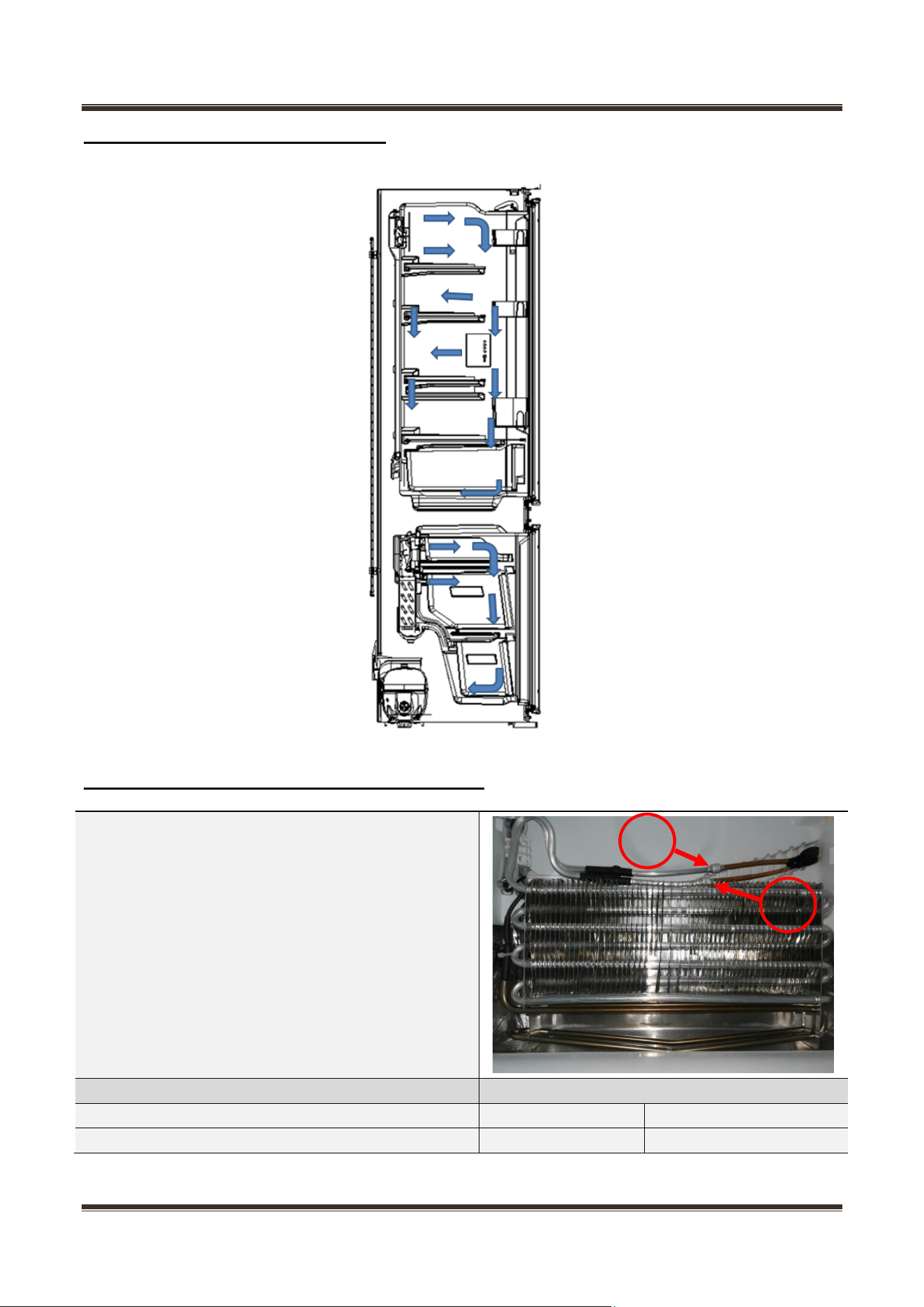
6.2 COOLING PIPELINE AND DRAIN PIPE INSIDE THE CABINET ........................................................................................ 22
6.3 CIRCULATING ROUTE OF COOLING AIR ..................................................................................................................... 23
6.4 WELDING POINTS IN CHAMBERS OR FOAM LAYER .................................................................................................... 23
6.5 WELDING POINT IN THE COMPRESSOR CASE ........................................................................................................... 24
7. DISMANTLING OF PARTS .................................................................................................................................. 25
7.1 PARTS ON THE DOOR ............................................................................................................................................... 25
7.2 PARTS INSIDE THE REFRIGERATOR .......................................................................................................................... 25
7.3 LIGHT SYSTEM .......................................................................................................................................................... 26
7.4 AIR DUCT COMPONENTS REFRIGERATING CHAMBER AND FAN MOTOR .................................................................... 27
7.5 AIR DUCT COMPONENTS IN FREEZING CHAMBER AND FAN MOTOR .......................................................................... 28
7.6 EVAPORATOR AND DEFROST SYSTEM ...................................................................................................................... 29
7.7 COMPRESSOR CASE................................................................................................................................................. 30
7.8 DISPLAY CONTROL BOARD ....................................................................................................................................... 35
7.9 MAIN CONTROL BOARD ............................................................................................................................................ 36
8. TEMPERATURE SENSING SYSTEM ................................................................................................................. 37
8.1 POSITION OF SENSORS ............................................................................................................................................ 37

Service Manual_
4
8.2 REPLACEMENT OF SENSORS ................................................................................................................................... 37
8.3 SENSOR WITHOUT TERMINAL REPLACEMENT........................................................................................................... 38
8.4 SENSOR RESISTANCE (R/T) ..................................................................................................................................... 39
9. FUNCTION AND OPERATION ............................................................................................................................ 40
9.1 DISPLAY OPERATION PANEL ..................................................................................................................................... 40
9.2 DISPLAY .................................................................................................................................................................... 40
9.3 TEMPERATURE SETTING ........................................................................................................................................... 41
9.4 MODE SETTING ......................................................................................................................................................... 41
9.4 LOCK AND UNLOCK SETTINGS ................................................................................................................................. 41
9.5 MEMORY FUNCTION .................................................................................................................................................. 41
9.6 OPEN DOOR ALARM (NONE) ..................................................................................................................................... 42
9.7 FAULT CODE AND SOLUTIONS ................................................................................................................................... 42
9.8 DEFROSTING FUNCTION ........................................................................................................................................... 42
9.9 TEST MODE ............................................................................................................................................................... 43
10. COMPRESSOR .................................................................................................................................................. 44
10.1 COMPRESSOR ON AND OFF CONTROL SPECIFICATIONS ........................................................................................ 44
10.2 INVERTER BOARD FAULT ANALYSIS ........................................................................................................................ 44
11. TROUBLESHOOTING METHOD ...................................................................................................................... 46
11.1 ERROR CODE E0 .................................................................................................................................................... 46
11.2 ERROR CODE E1 / E2 / E3 / E4 / E5 / E7 / E8 / EE / C9 / CC / F4 ..................................................................... 47
11.3 ERROR CODE E6 .................................................................................................................................................... 48
11.4 ERROR CODE EF .................................................................................................................................................... 49
11.5 ERROR CODE EH ................................................................................................................................................... 50
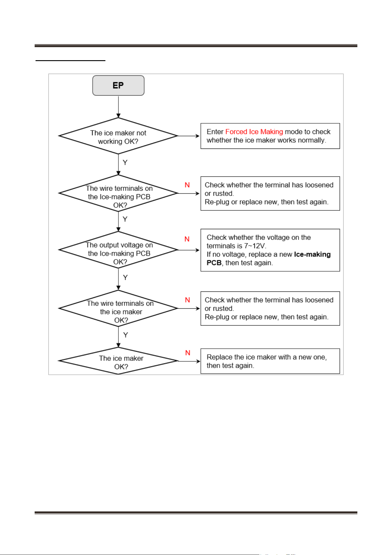
11.6 ERROR CODE EP ................................................................................................................................................... 51
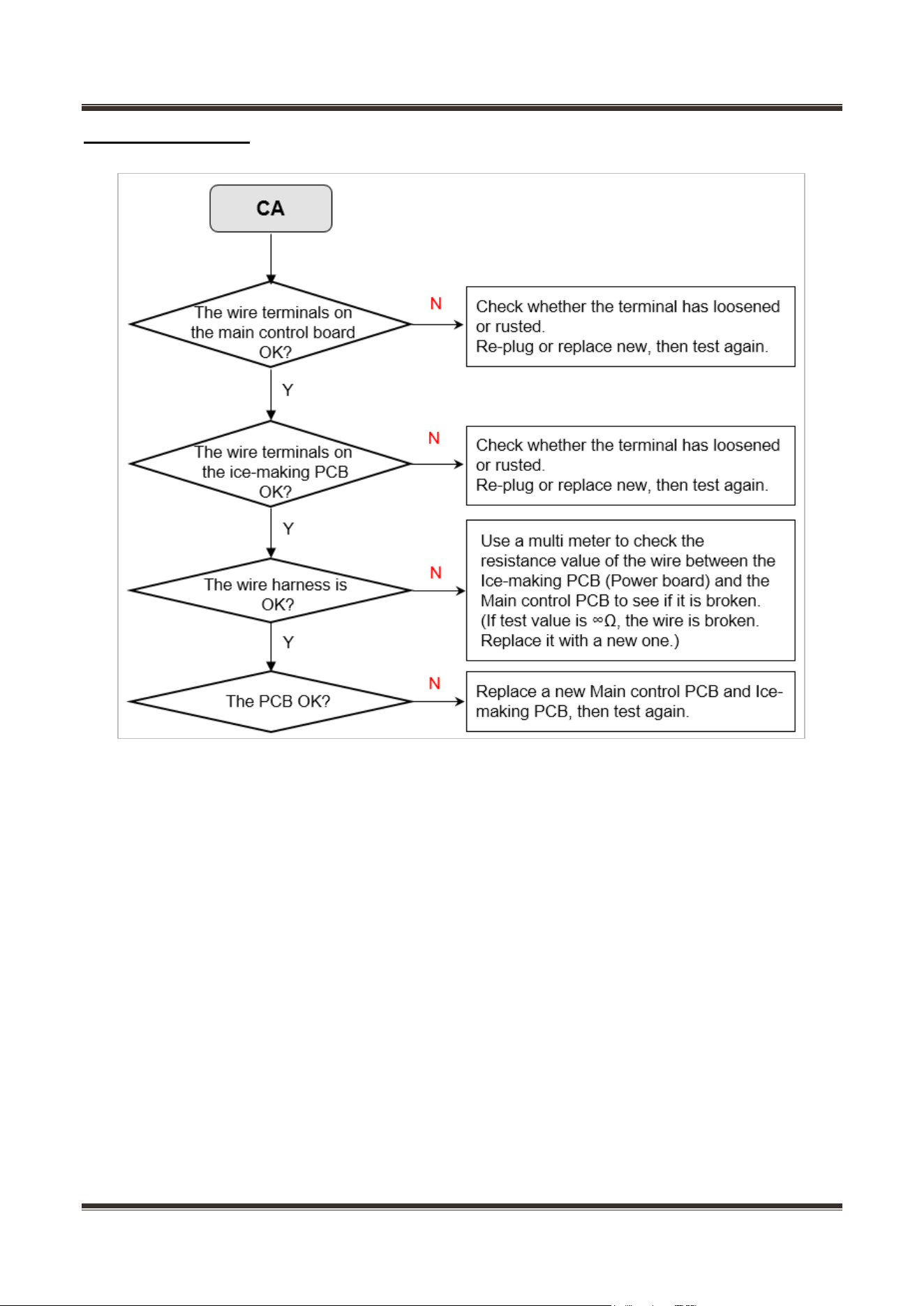
11.7 ERROR CODE CA ................................................................................................................................................... 52
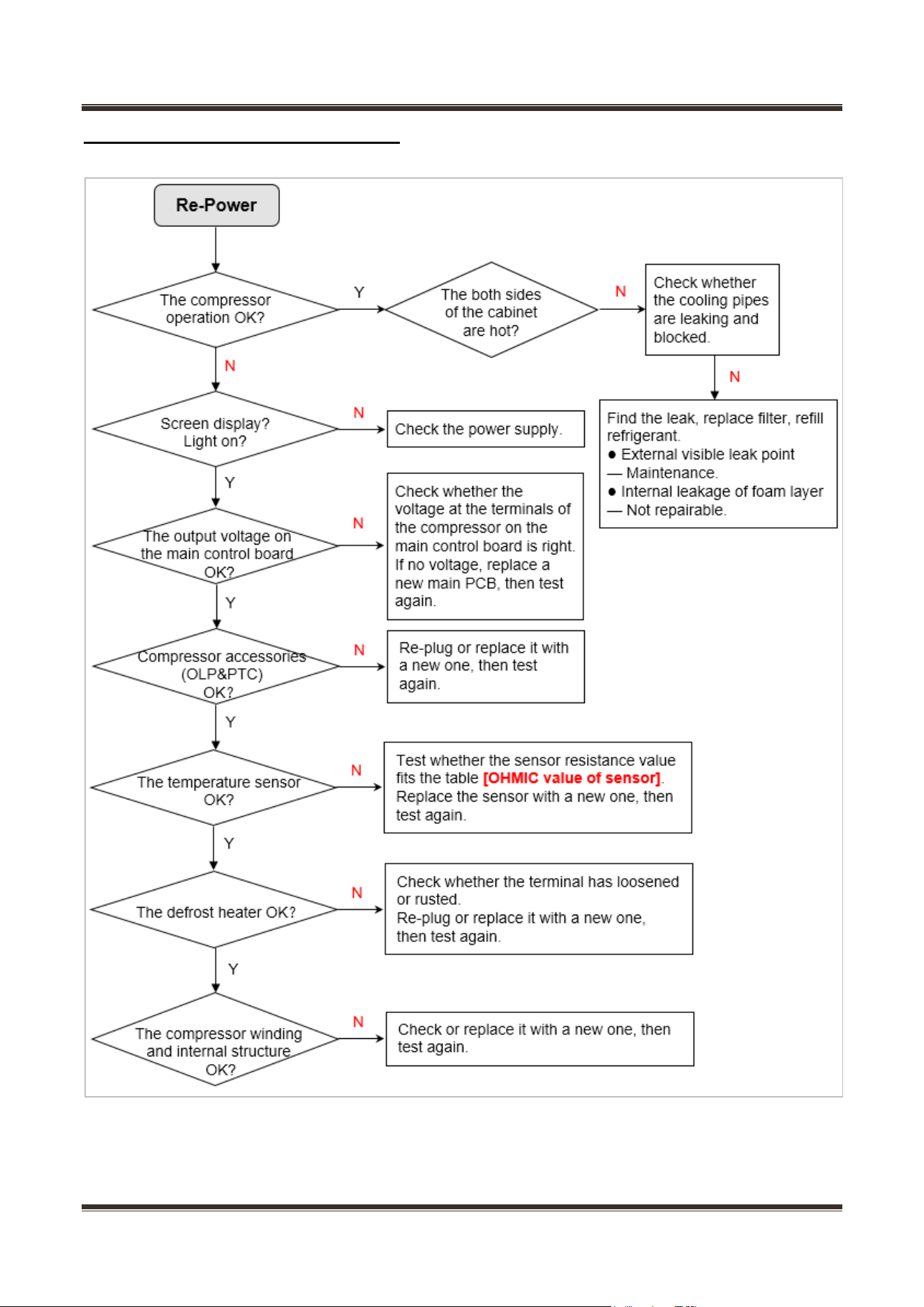
11.8 NOT COOLING IN ALL THE CHAMBERS ..................................................................................................................... 53
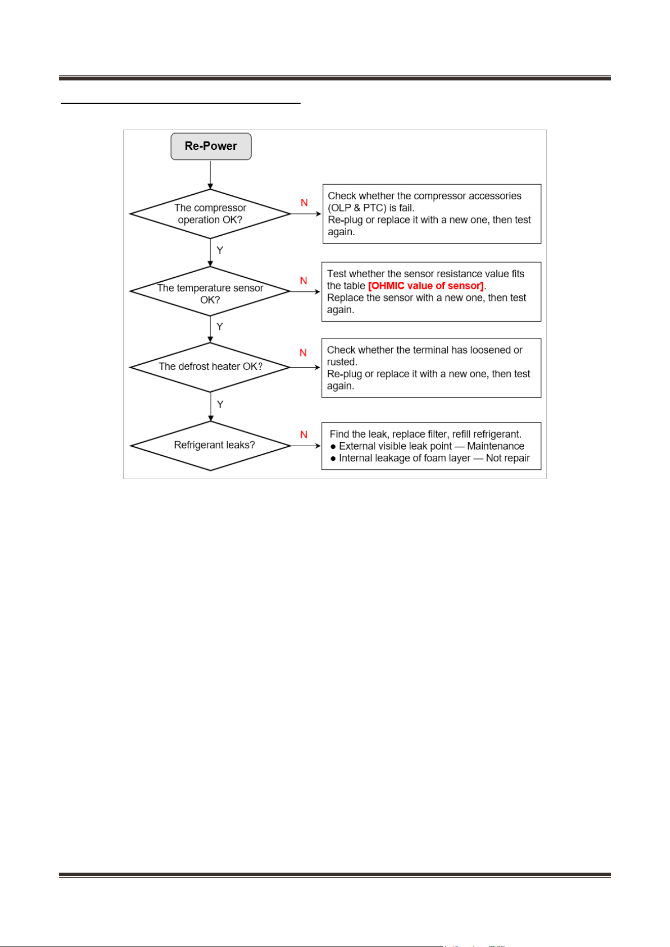
11.9 POOR COOLING IN ALL THE CHAMBERS ................................................................................................................. 54
11.10 OVERCOOLING IN THE REFRIGERATED CHAMBER ................................................................................................ 55
11.11 NOT & POOR COOLING IN THE REFRIGERATED CHAMBER ................................................................................... 56
11.12 NO WORKING OF COMPRESSOR ........................................................................................................................... 57
11.13 CONDENSATION & FROST .................................................................................................................................... 58
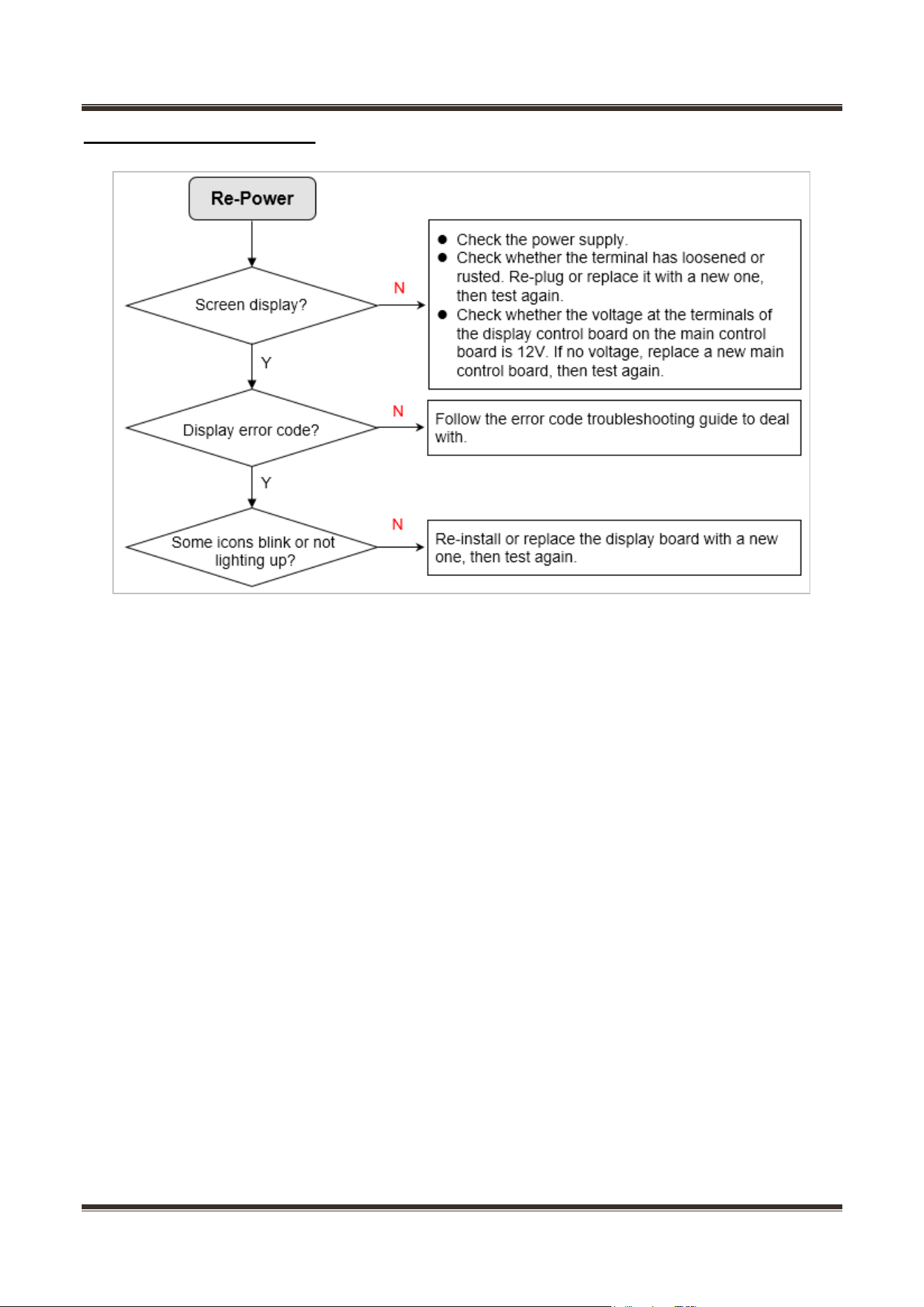
11.14 DISPLAY PANEL FAILURE ....................................................................................................................................... 59
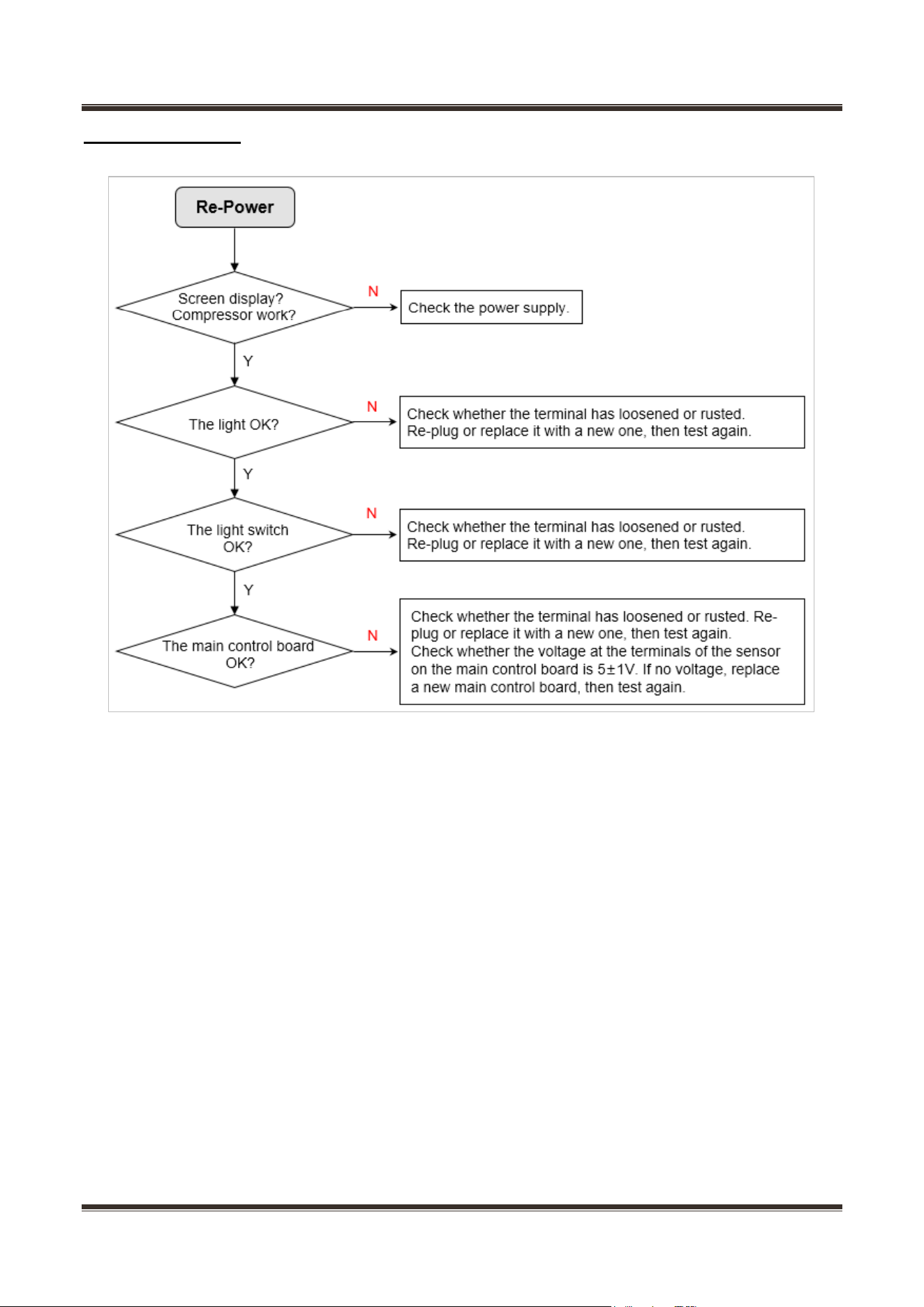
11.15 LIGHT FAILURE ...................................................................................................................................................... 60
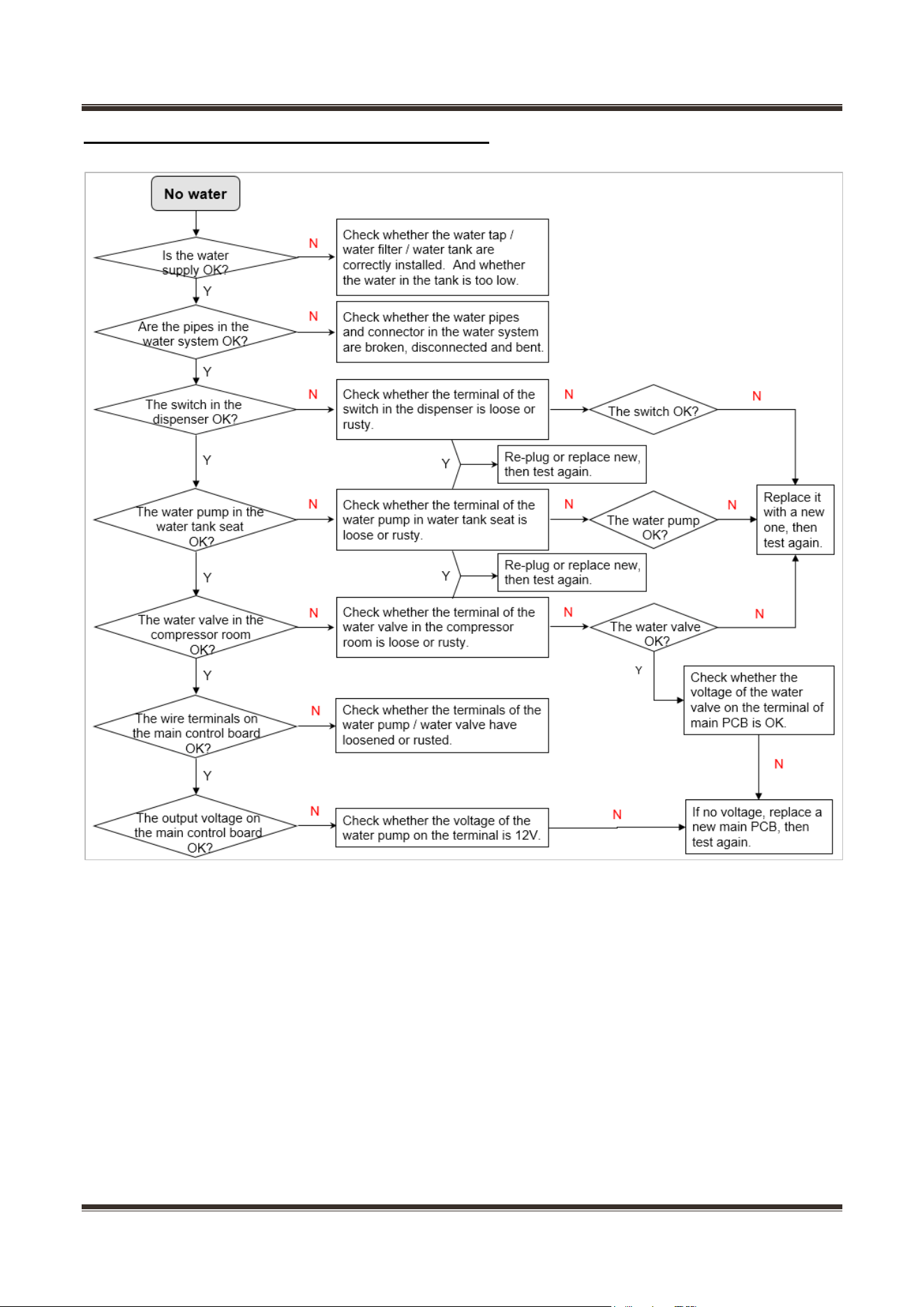
11.16 NO WATER FROM THE ICE & WATER DISPENSER .................................................................................................. 61
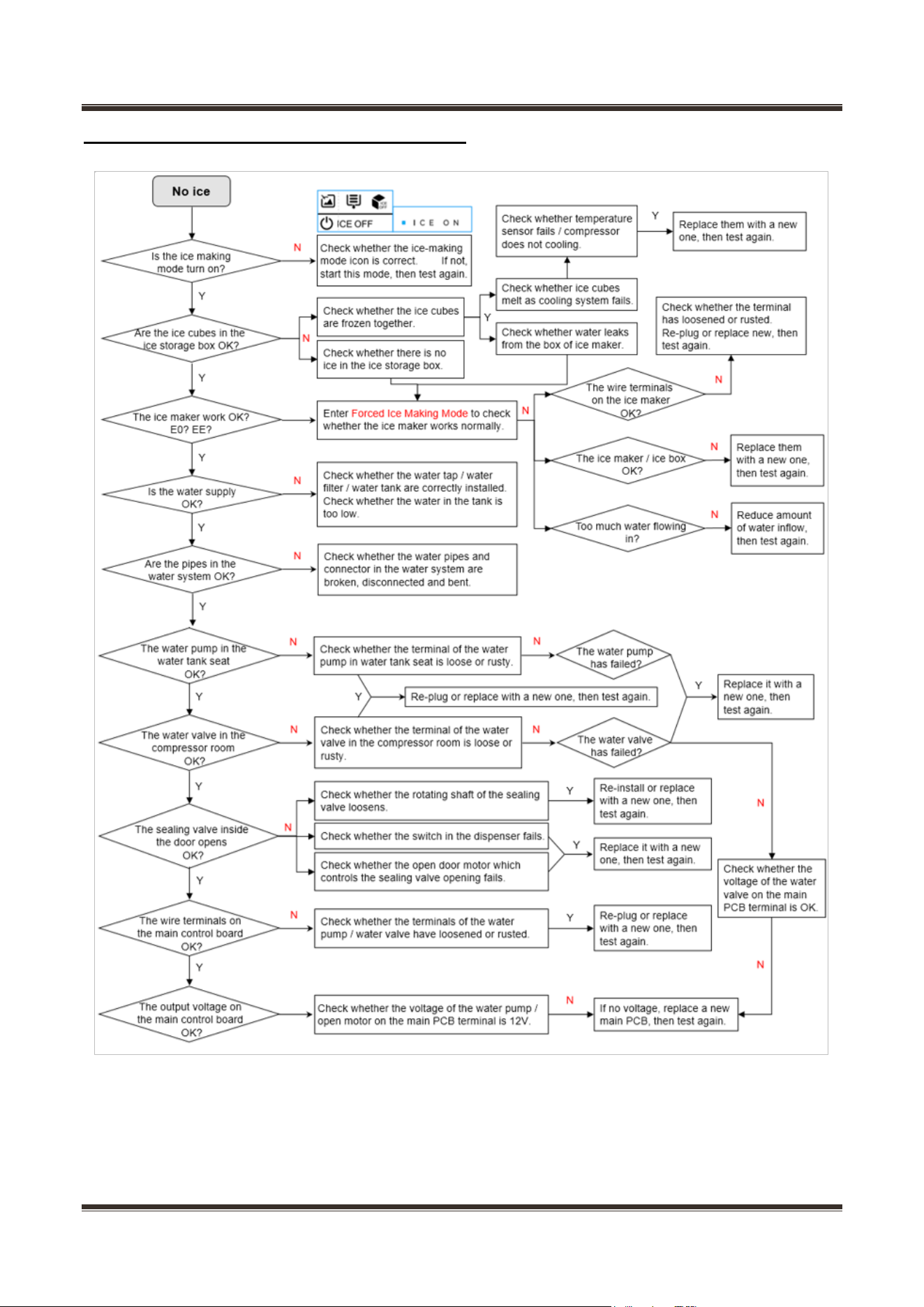
11.17 NO ICE FROM THE ICE & WATER DISPENSER ........................................................................................................ 62
11.18 NOISE ................................................................................................................................................................... 63
12. MAINTENANCE TOOLING, EQUIPMENT AND MATERIAL ......................................................................... 64
13. PRODUCT EXPLODED VIEW AND SPARE PARTS LIST ............................................................................. 68
Service Manual_
5
1. 1. Significant update notes
(SM No.)
Date
Author
Description
Service Manual_
6
2. Safety Warning Code
2.1 Warning for operation safety
Important Safety Instructions
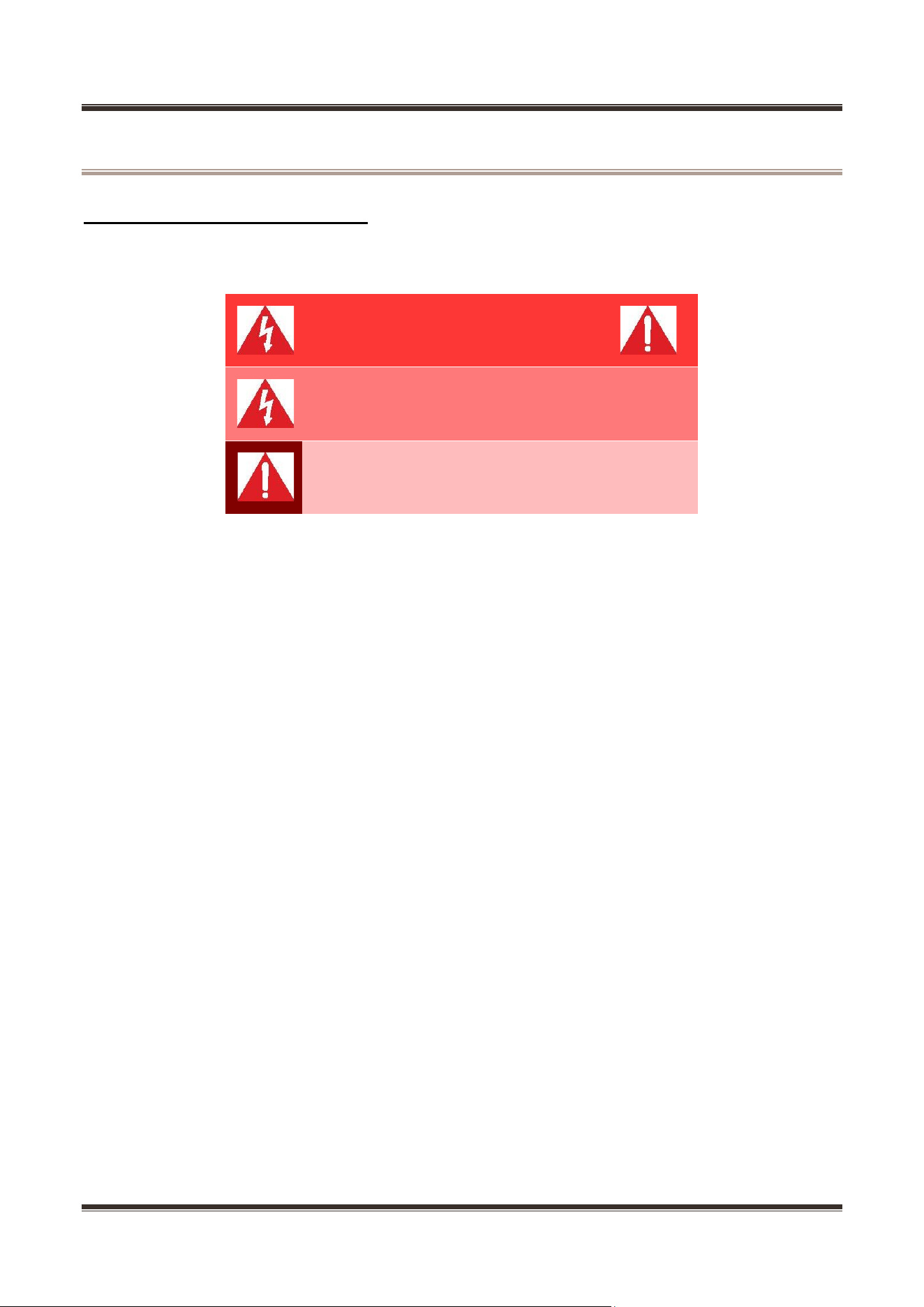
CAUTION
RISK OF ELECTRIC SHOCK
DO NOT OPEN
This symbol indicates that dangerous voltage
constituting a risk of electric shock is present
within your freezer.
This symbol indicates that there are important
operating and maintenance instructions in the
literature accompanying your freezer.
WARNING
1) Read these instructions.
2) Keep these instructions.
3) Heed all warnings.
4) Follow all instructions.
5) Do not use this appliance near water.
6) Clean only with a damp cloth.
7) Do not block any ventilation openings.
8) Install in accordance with the manufacturer’s instructions.
9) Do not install near any heat sources, such as radiators, heat registers, stoves, or
other apparatus that produce heat.
10) Do not defeat the safety purpose of the polarized or grounding-type plug. A
polarized plug has two blades with one wider than the other. A grounding type plug has two
blades and a third grounding prong. The wide blade or the third prong are provided for your
safety. If the provided plug does not fit into your outlet, consult an electrician for
replacement of the obsolete outlet.
11) Protect the power cord from being walked on or pinched, particularly at plugs,
convenience receptacles, and the point where they exit from the appliance.
12) Do not attempt to modify or extend the power cord of this appliance.
13) Unplug this appliance during lightning storms or when it will not be used for long
periods of time.
14) Make sure that the available AC power matches the voltage requirements of this
appliance.
Service Manual_
7
CONNECTING ELECTRICITY
Electrical Shock
Hazard.
Plug into a grounded 3-prong outlet.
Do not remove the ground prong.
Do not use an adapter.
Failure to follow these instructions can
result in death, fire, or electrical shock.
WARNING
Electric Shock Hazard
Failure to follow these instructions can result in electric shock, fire, or
death.
1) WARNING–Keep ventilation openings, in both the freezer and the built-in structure,
clear of obstruction.
2) WARNING–Do not touch the interior of the freezer with wet hands. This could result
in frost bite.
3) WARNING–Do not use mechanical devices or other means to accelerate the
defrosting process, other than those recommended by the manufacturer.
4) WARNING–Do not damage the refrigerant circuit.
5) WARNING–Do not damage the refrigerant tubing when handling, moving, or using
the freezer.
6) WARNING–DANGER–Never allow children to play with, operate, or crawl inside the
freezer. Risk of child entrapment. Before you throw away your old freezer:
6-1) Take off the doors
6-2) Leave the shelves in place so that children may not easily climb inside
7) Unplug the freezer before carrying out user maintenance on it.
8) This freezer can be used by children age eight years and older and persons with
reduced physical or mental capabilities or lack of experience and knowledge if they are
given supervision or instruction concerning the use of the freezer in a safe way and
understand the hazards involved. Children should not play with the freezer. Cleaning and
maintenance should not be performed by children without supervision.
9) If a component part is damaged, it must be replaced by the manufacturer, its service
agent, or similar qualified persons in order to avoid a hazard.
10) Please dispose of the freezer according to local regulations as the freezer contains
flammable gas and refrigerant.
11) Follow local regulations regarding disposal of the freezer due to flammable
refrigerant and gas. All refrigeration products contain refrigerants, which under the
guidelines of federal law must be removed before disposal. It is the consumer's
Service Manual_
8
responsibility to comply with federal and local regulations when disposing of this product.
12) This freezer is intended to be used in household and similar environments.
13) Do not store or use gasoline or any flammable liquids inside or in the vicinity of this
freezer.
14) Do not use extension cords or ungrounded (two-prong) adapters with this freezer. If
the power cord is too short, have a qualified electrician install an outlet near the freezer.
Use of an extension cord can negatively affect the freezer’s performance.
Grounding requirement
This freezer must be grounded. This freezer is equipped with a cord having a
grounding wire with a grounding plug. The plug must be inserted into an outlet that is
properly installed and grounded.
Improper use of the grounding plug can result in a risk of electric shock. Consult a
qualified electrician or service person if the grounding instructions are not completely
understood, or if doubt exists as to whether the freezer is properly grounded.
2.2 Safety instruction for refrigerant
Explosion Hazard.
Keep flammable materials and vapors, such as gasoline, away from freezer. Failure to
do so can result in fire, explosion, or death.
Safety instruction for refrigerant
DANGER–Risk of Fire or Explosion. Flammable Refrigerant Used. To Be Repaired Only
By Trained Service Personnel. Do Not Use Mechanical Devices. Do Not Puncture
Refrigerant Tubing. CAUTION–Risk of Fire or Explosion. Flammable Refrigerant Used.
Consult Repair Manual/Owner’s Guide Before Attempting To Service This Product. All
Safety Precautions Must be Followed. CAUTION–Risk of Fire or Explosion. Dispose of
Properly In Accordance With Federal Or Local Regulations. Flammable Refrigerant
Used. CAUTION–Risk of Fire or Explosion Due To Puncture Of Refrigerant Tubing;
Follow Handling Instructions Carefully.
Flammable Refrigerant Used.
Service Manual_
9
3. Installation and commissioning
3.1 Handling
Handling
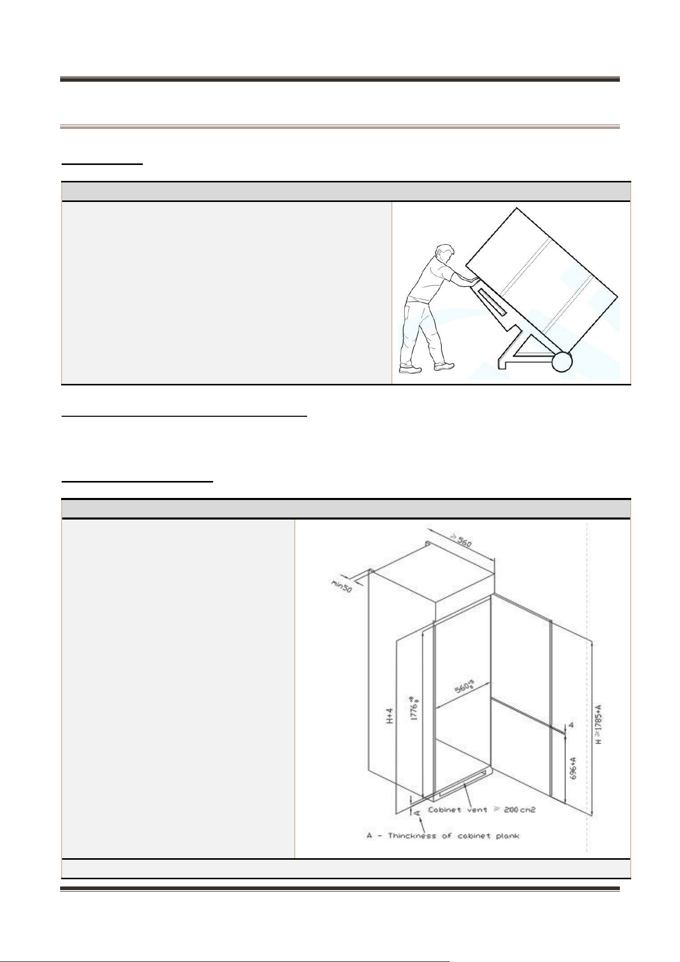
1) Protect the refrigerator in moving it,
Same as shown as right
photo, please move it by handcart with cushion
2) Remove all packing materials and bottom cushion,
then move into house for placement
3) After moving it to appropriate location, wait for 2
hours before power on.
3.2 Door Disassembly and Assembly
The refrigerator door needs to be dismantled if it cannot enter the room in the whole.
3.3 Installation location
Installation location
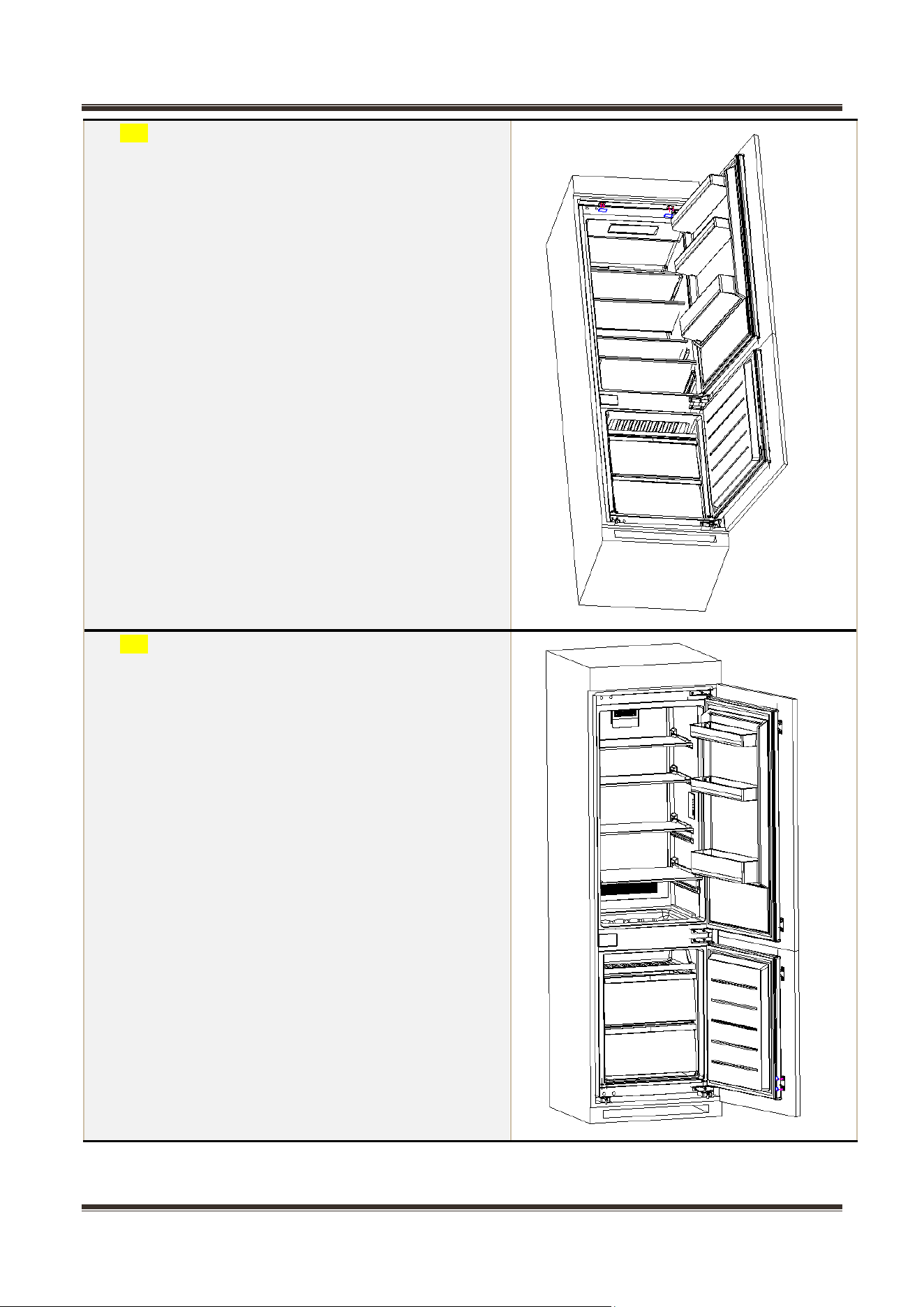
Refrigerator installed in the cabinet and
the size requirements such as the right
figure.
Installation Steps
Service Manual_
10
1) Push the refrigerator into the cabinet and adjusted
it to make the baffle flange touch the edge of the
cabinet, and the supporting limit is hooked to the
bottom edge of the cabinet.
1) Fix the lower support with screws, and cover the
screw cap.
Service Manual_
11
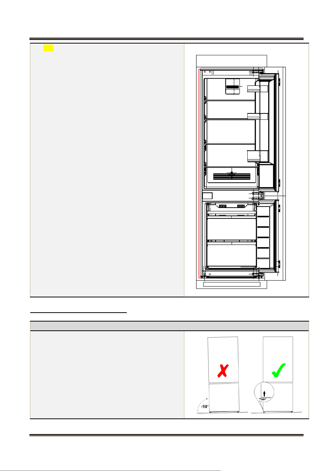
1) Fix the top baffle to the top of the cabinet with
screws, and cover the screw cap.
1) The lower door of the cabinet is opened to the
maximum angle, and the lower door of the
refrigerator is opened to the corresponding
position. Sliding the block to make inner edge
align with the door edge, then fix the block to the
door with screw and cover the screw cap. Fix the
top door to the cabinet door in the same way.
Service Manual_
12
2) The sealing strip in the accessory is sealed in
the gap between the cabinet and the refrigerator.
Installation is complete.
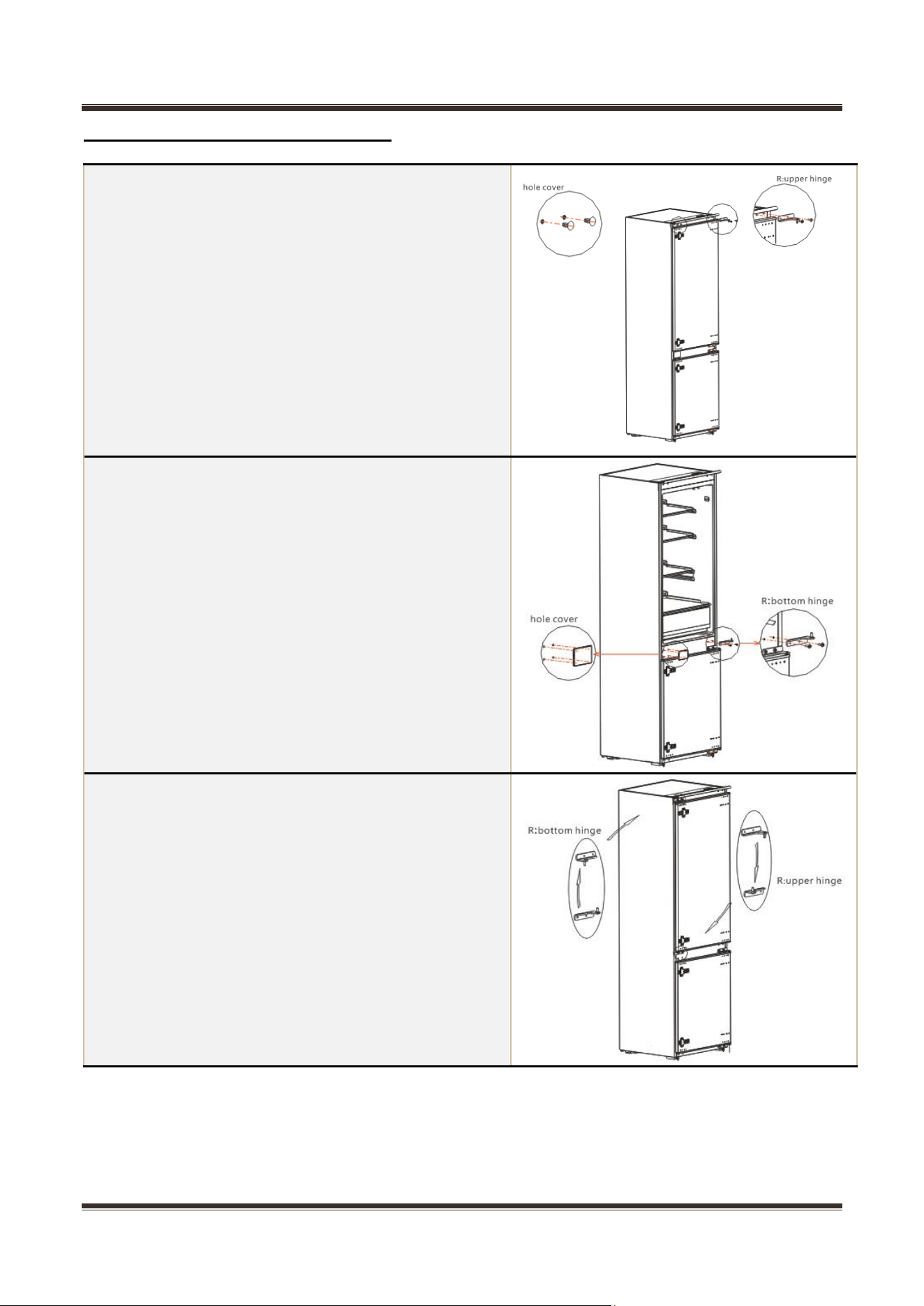
3.4 Leveling of the refrigerator
Leveling of the refrigerator
If the refrigerator cannot be placed steadily, adjust the
footing to level it.
Service Manual_
13
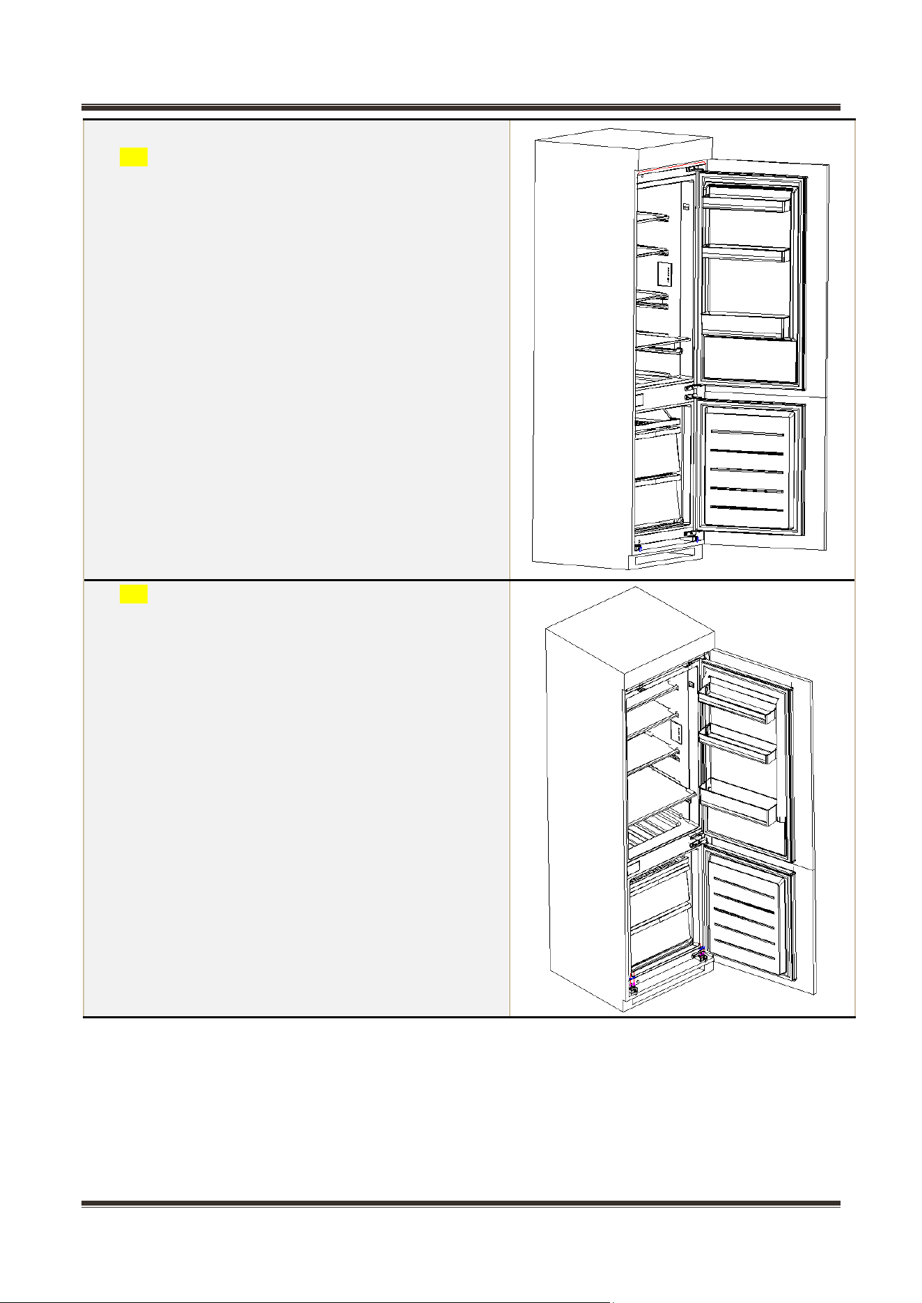
3.5 Left or right open door reversal
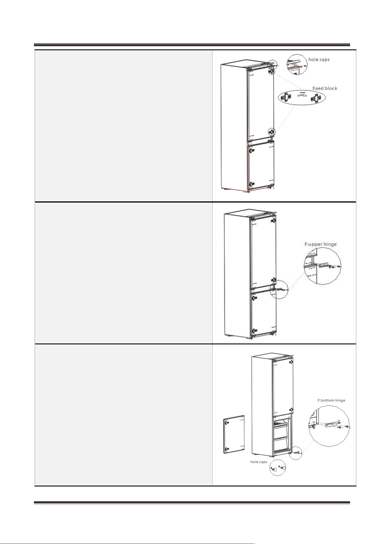
1. Power off the refrigerator, and remove all objects from
the door trays.
2. Remove the upper hinge and hole caps of refrigerator
door.
3. Remove the refrigerator door, the bottom hinge and the
hole cover.
4. Exchange the R:bottom hinge and R:upper
hinge ,then assemble them and assemble top hole
caps .
Service Manual_
14
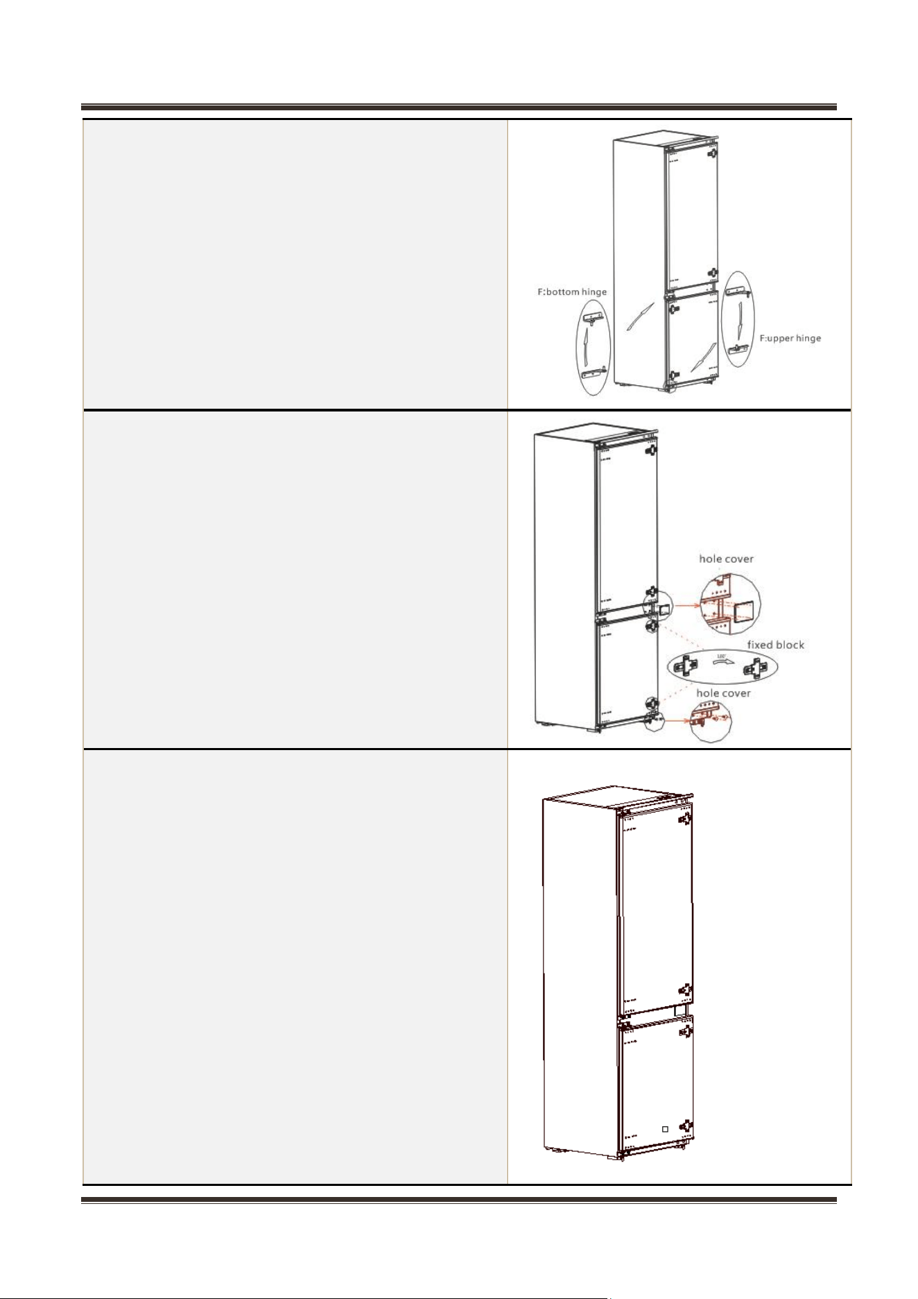
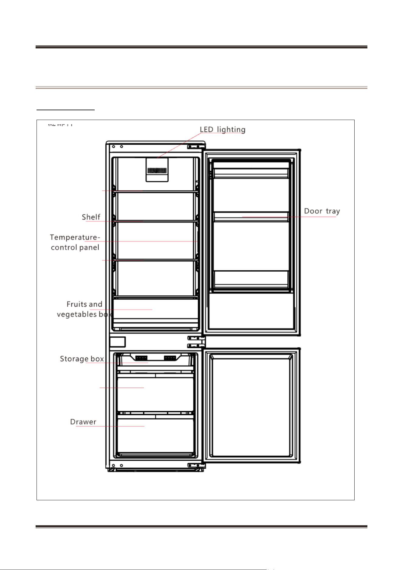
5. Remove the fixed block of refrigerator door and rotate
it for 180°, assemble it on other side of refrigerator door.
6. Remove the upper hinge of refrigerator door.
7. Remove the freezer door, the bottom hinge and the
hole caps.
Service Manual_
15
8. Exchange the F:bottom hinge and F:upper hinge ,then
assemble them.
9. Remove the fixed block of refrigerator door and rotate
it for 180°, assemble it on other side of refrigerator door.
10. Finished
Service Manual_
16
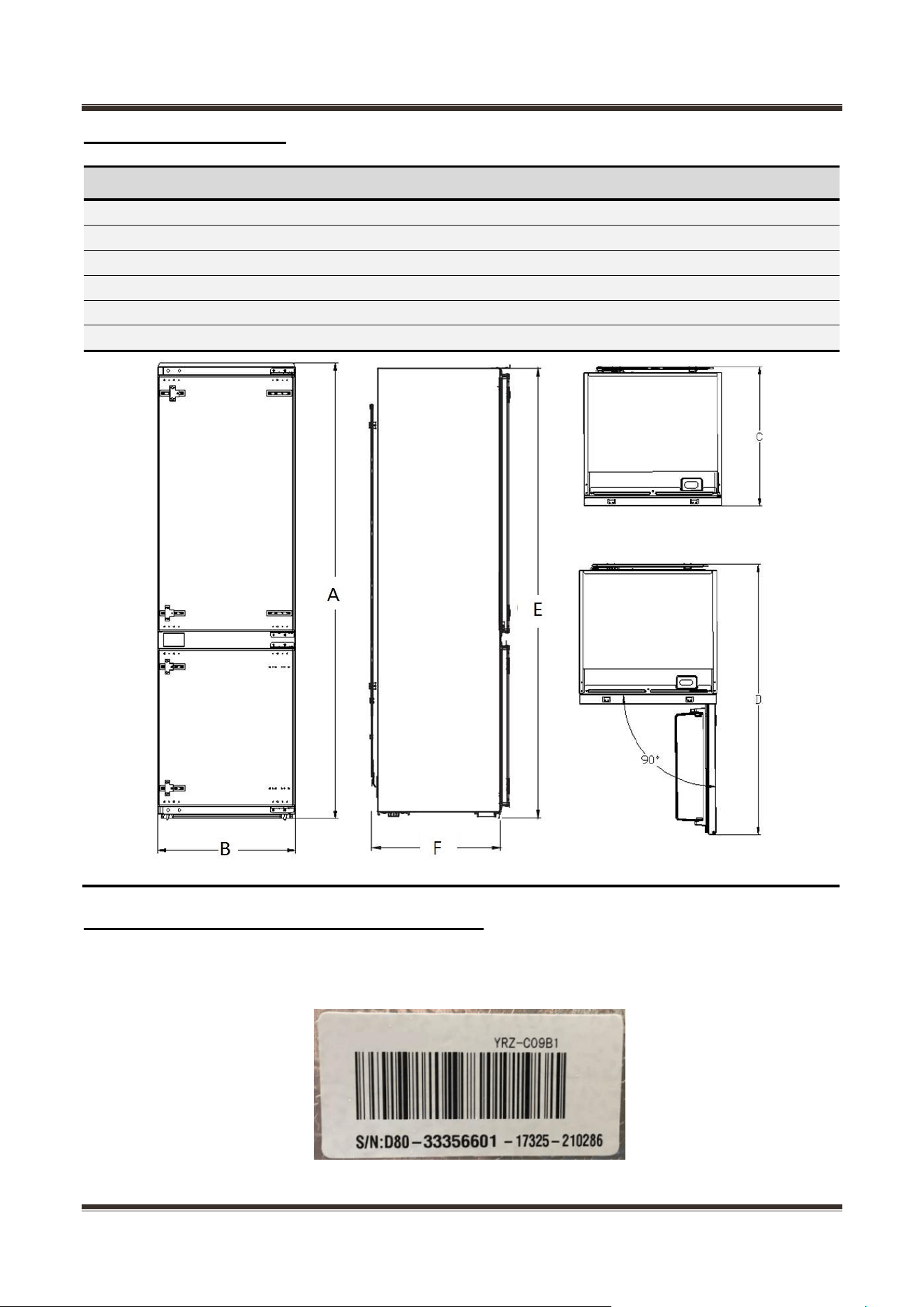
4. Main parts and external dimension
4.1 Main parts
(The picture is only for reference, and specific appearance and configuration are subject to the
real product)
Service Manual_
17
4.2 External dimension
Description
Code
Size (mm)
Height to Top of Case
A
1785
Width
B
540
Depth w/o Handles
C
545
Depth (90 deg. with Door Open)
D
1060
Height to match the cabinet
E
1775
Depth to match the cabinet
F
510
(The picture is only for reference)
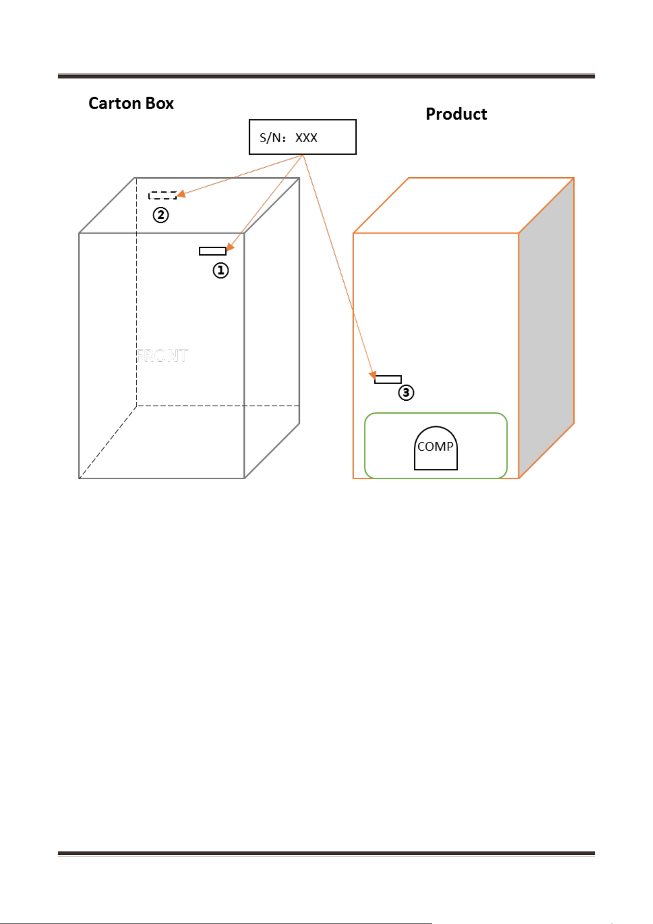
4.3 Midea product serial number and location
1) Product Serial Number —Including order number, production date and other information. When the
product occur problem, it needs to be recorded or photographed and provided to us.
2)Paste location
Service Manual_
18
Some products also have S/N on the lower part of the right side of the Cabinet.
Service Manual_
19
5. Electric control system
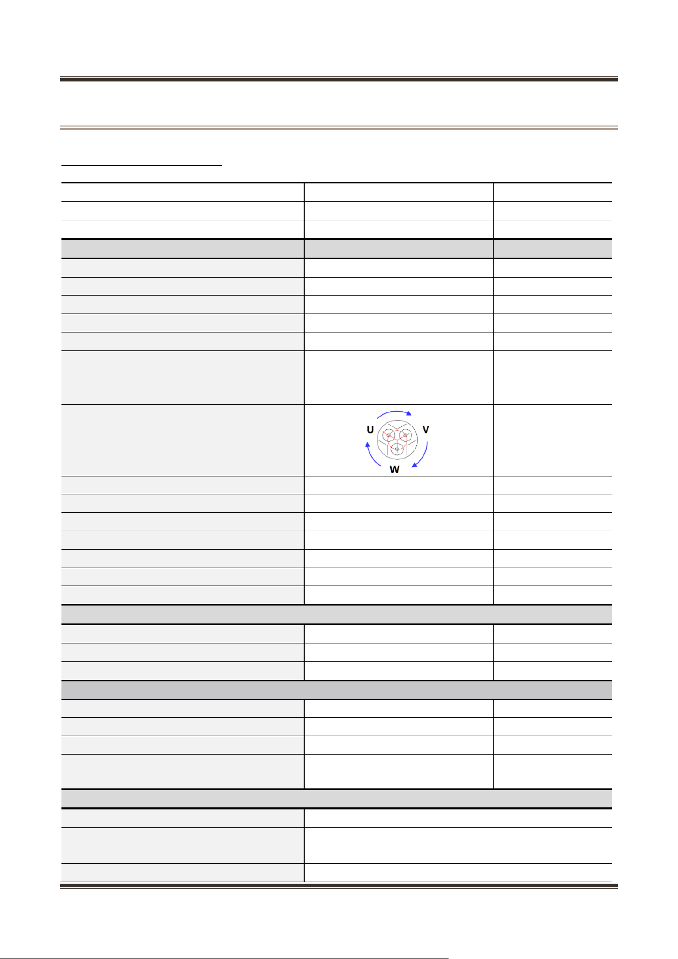
5.1 Electrical parameters
Applicable Model
HD-332RWEN
Product Model
CE-BCD255WX-JT
Rated Voltage
200-240V, 50Hz
Item
Specification
Refrigerant
R600a
Compressor
DZ75Z1A
Starting device type
Inverter
The COP of compressor
1.76 (W/W)
The max cooling capacity of compressor
173W
Winding resistance of compressor
wiring terminal (20℃)
U-W: 22.6Ω±7%
U-V: 22.6Ω±7%
V-W: 22.6Ω±7%
Winding resistance picture
Starter (PTC)
None
Overload protector (OLP)
None
Integrate PTC+OLP
None
Inverter driver board
Have
Capacitor
None
Power filter (EMI)
None
Power reactor (EU EMC)
None
Motor
Fan motor of the freezing chamber
DC12V, 1.8W, 2700r/min
Fan motor of the refrigerating chamber
DC12V, 1.0W, 2100 r/min
Electric damper
None
Lights
Lights inside the refrigerating chamber
12V/2W
Lights inside the freezing chamber
None
Others Lights
None
Switch of the light
■ Mechanical switch
□ Magnetism control switch
Defrosting parts
Defrosting sensor
NTC B3839 ( B5/25=3839K±2% )
Fuse in freezing chamber
230V, 77(0 ~ -5) ℃
Defrost heater in freezing chamber
230V, 170W
Service Manual_
20
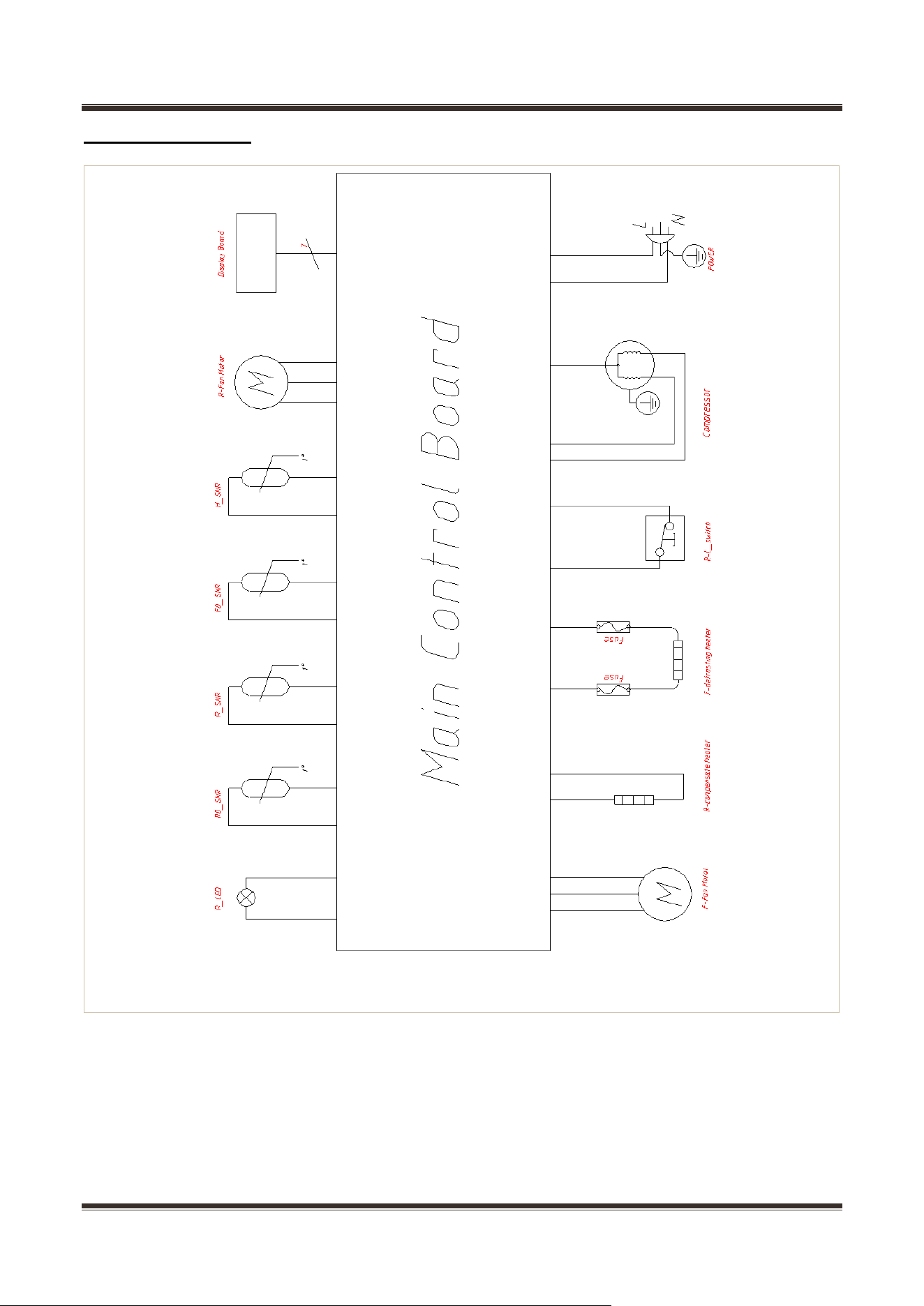
5.2 Circuit diagram
F: Freezer R: Refrigerator RD: Refrigerator defrost FD: Freezer defrost
H: Ambient temperature
Service Manual_
21
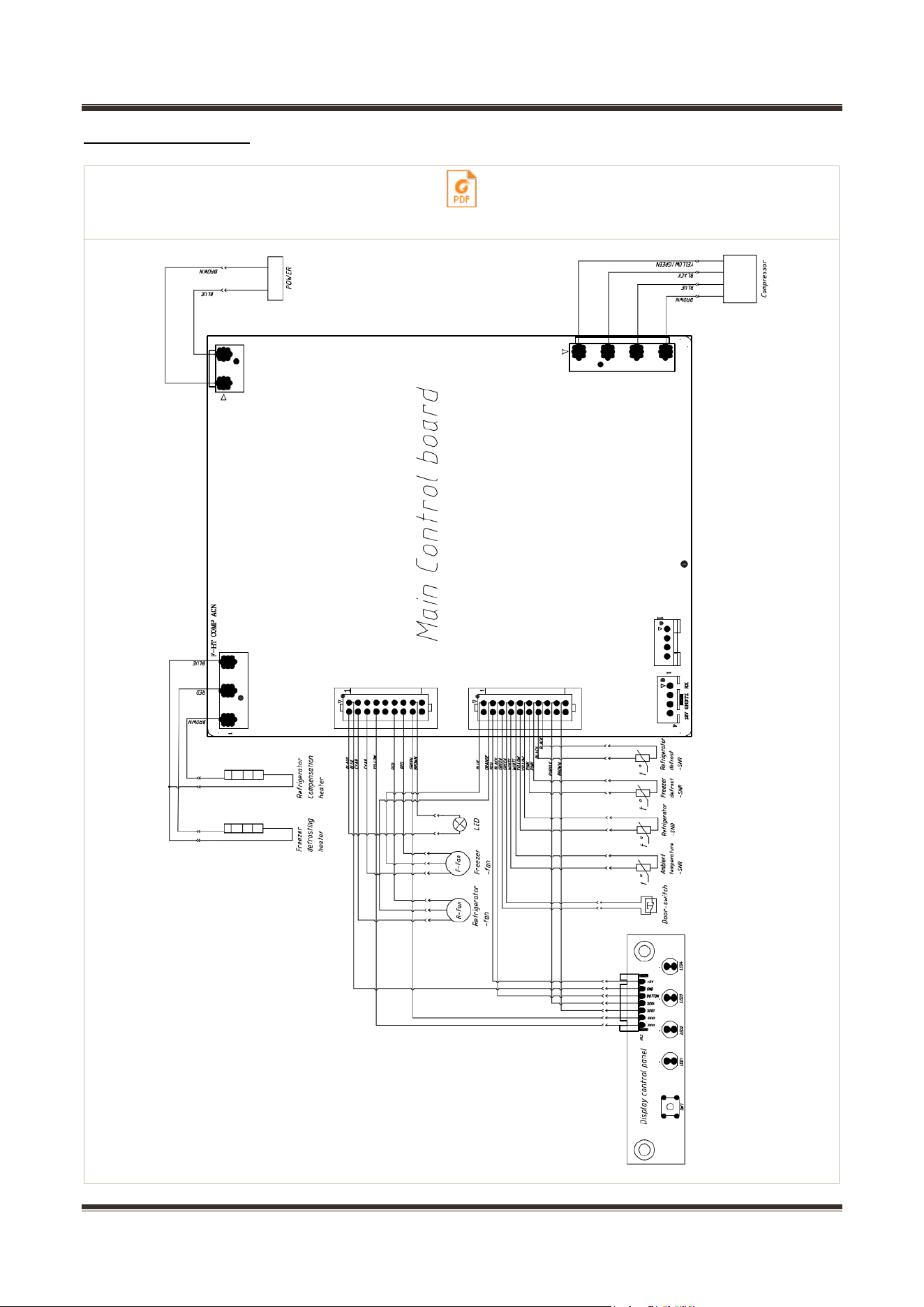
5.3 Wiring diagram
REF_Wiring diagram_CE-BCD255WX-JT_22031020012223接线图.pdf
Service Manual_
22
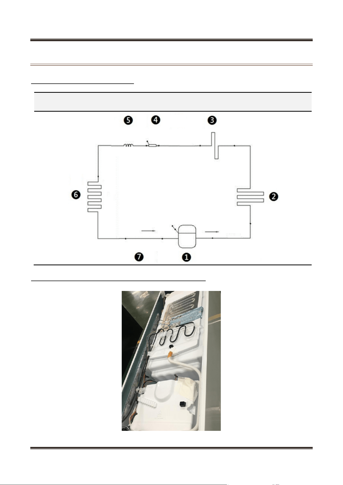
6. Refrigeration system
6.1 Refrigerating piping system
❶Compressor→❷ condenser→❸Anti-condensation tube→❹ Dry filter→❺ Capillary tube→❻
Evaporator→❼ Suction tube→❶Compressor
6.2 Cooling pipeline and drain pipe inside the cabinet
Service Manual_
23
6.3 Circulating route of cooling air
6.4 Welding points in chambers or foam layer
1) Welding points on freezer evaporator
Welding point
Pipe outer diameter (mm)
1- Freezer capillary and inlet of evaporator
Copper pipe: Φ6
Aluminum pipe: Φ6.35
2- Heat transition tube and outlet of evaporator
Copper pipe: Φ6
Aluminum pipe: Φ6.35
2
1
Service Manual_
24
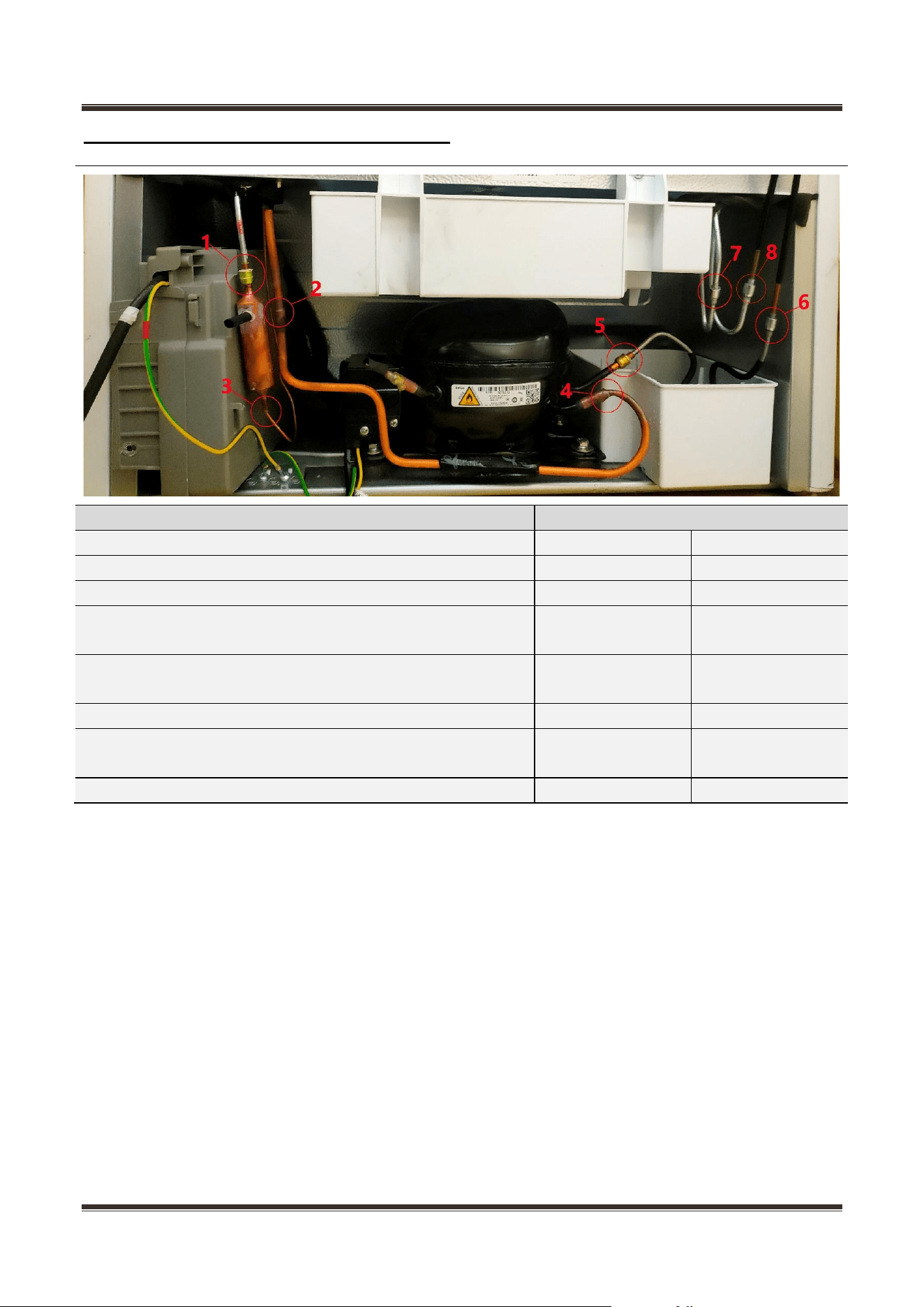
6.5 Welding point in the compressor case
Welding point
Pipe outer diameter (mm)
1- Outlet of anti-condensation tube and inlet of dry filter
Steel pipe: Φ4. 0
Copper pipe: Φ5.0
2- transition tube and Suction connection tube
Copper pipe: Φ6.0
Copper pipe: Φ6.0
3- Outlet of dry filter and inlet of freezer capillary
Copper pipe: Φ2.8
Copper pipe: Φ1.8
4- Suction connection pipe and compressor intake tube
Copper pipe: Φ6.0
Copper pipe:
Φ8.17
5- Compressor outlet tube and inlet of venting connection
tube
Copper pipe:
Φ6.17
Steel pipe: Φ4.0
6- Outlet of venting connection tube and inlet of condenser
Copper pipe: Φ4.0
Steel pipe: Φ4.0
7- Outlet of side panel tube and inlet of anti-condensation
tube
Steel pipe: Φ4.0
Steel pipe: Φ4.0
8- Outlet of condenser and inlet of side panel tube
Steel pipe: Φ4.0
Steel pipe: Φ4.0
Service Manual_
25
7. Dismantling of parts
7.1 Parts on the door
Door seal
Door seal is installed into door liner groove.
1) Open the refrigerator door.
2) Take the door seal ① out of door liner.
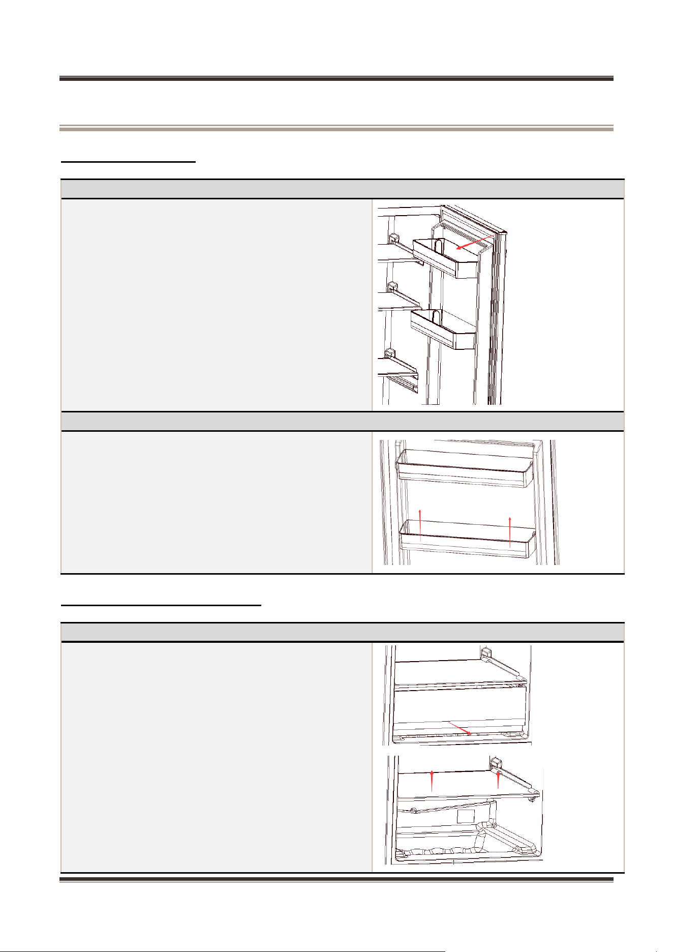
Door tray
While squeezing it inward, lift up the baffle and take it
out from refrigerator liner.
7.2 Parts inside the refrigerator
Refrigerator Fruit box cover
Remove the crisper cover of ref. compartement accordin
g to below steps:
1) 1)Take out the crisper firstly.
2) 2)Pull out the crisper cover completely.
Service Manual_
26
Shelves
1)Lift up the division plate with a proper force and pull it
out towards yourself.
Drawer
The drawer is located at the bottom of freezing
chambers;
1) Pull the drawer out completely; Lift it up slightly and
take it out from the refrigerator.
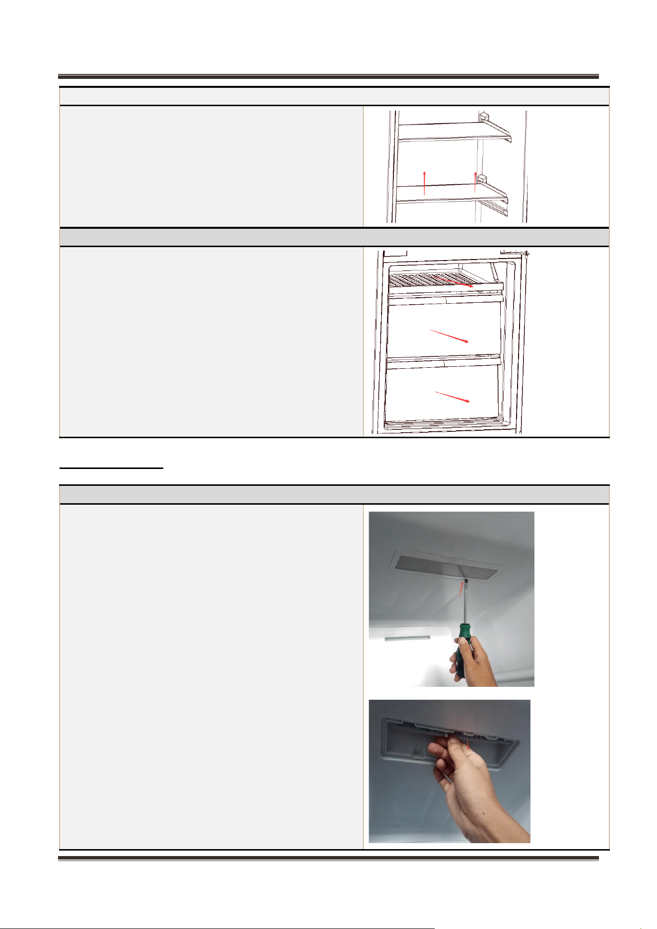
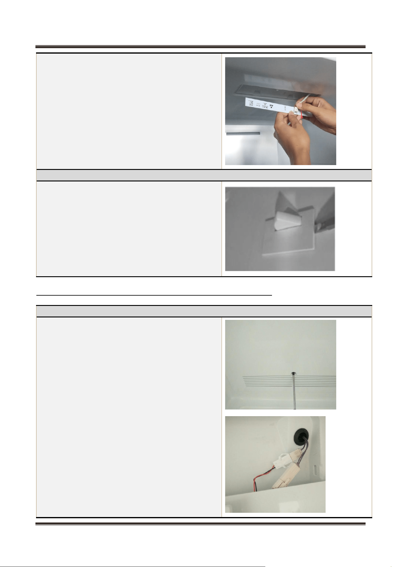
7.3 Light system
Light
Light of the refrigerating chamber is located upper
chamber
1) Remove the lamp cover
2) Remove the LED lamp
3) Remove the LED lamp terminal
4) The reverse process can complete installation.
Service Manual_
27
Light switch
There is a light switch on the side wall of the
refrigerating chamber.
1)Loosen the hook with small normal screwdriver and
pull out the switch until the wire connector reveals.
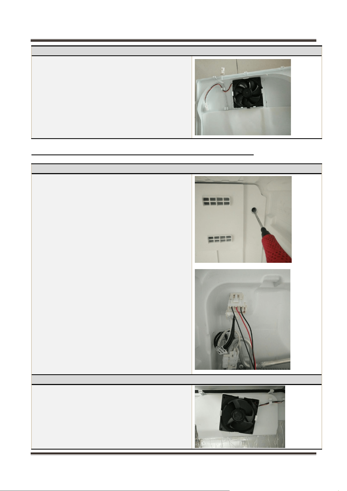
7.4 Air duct components refrigerating chamber and fan motor
Air duct components in freezing chamber
All accessories in the freezing chamber should be
dismantled before removing the air duct components.
1)Remove 1 screws on the cover plate of the
refrigerating air duct using a cross screwdriver.
2)Pull out the connector terminal of the fan motor.
Service Manual_
28
Fan motor of air duct
1)The fan is fastened with clasps and can be removed
directly;
2)Change the fan, the reverse operation for assembly
7.5 Air duct components in freezing chamber and fan motor
Air duct components in freezing chamber
All accessories in the freezing chamber should be
dismantled before removing the air duct components.
1) Remove 1 screws on the cover plate of the
freezing air duct using a cross screwdriver.
2) Pull out the connector terminal of the fan motor.
Fan
1、 The fan is fastened with clasps and can be removed
directly;
2、 Change the fan, the reverse operation for
assembly
Service Manual_
29
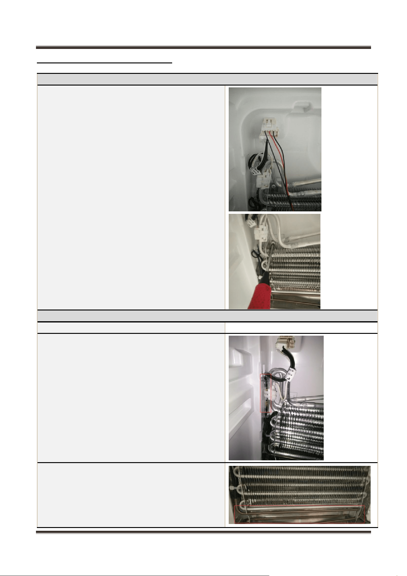
7.6 Evaporator and Defrost system
Evaporator in freezing chamber
1) Remove the air duct components in freezing
chamber.
2) Disconnect all connectors.
3) Remove the welding on inlet and outlet tubes.
4) Remove one screws which are used to fix the
evaporator and remove the evaporator.
Components on the evaporator
Defrost thermostat
None
Fuse
The fuse is located on top of the evaporator
1) connect the fuse connector.
2) Cut off the band which fixes the fuse.
3) Separate the fuse and the evaporator.
Defrost heater
The defrost heater is located at bottom of the evaporator.
1) Disconnect the connector of defrost heater.
2) Cut off the band which fixes the defrost heater.
3) Take off the defrost heater from the evaporator.
Service Manual_
30
7.7 Compressor case
Rear cover and compressor case
None
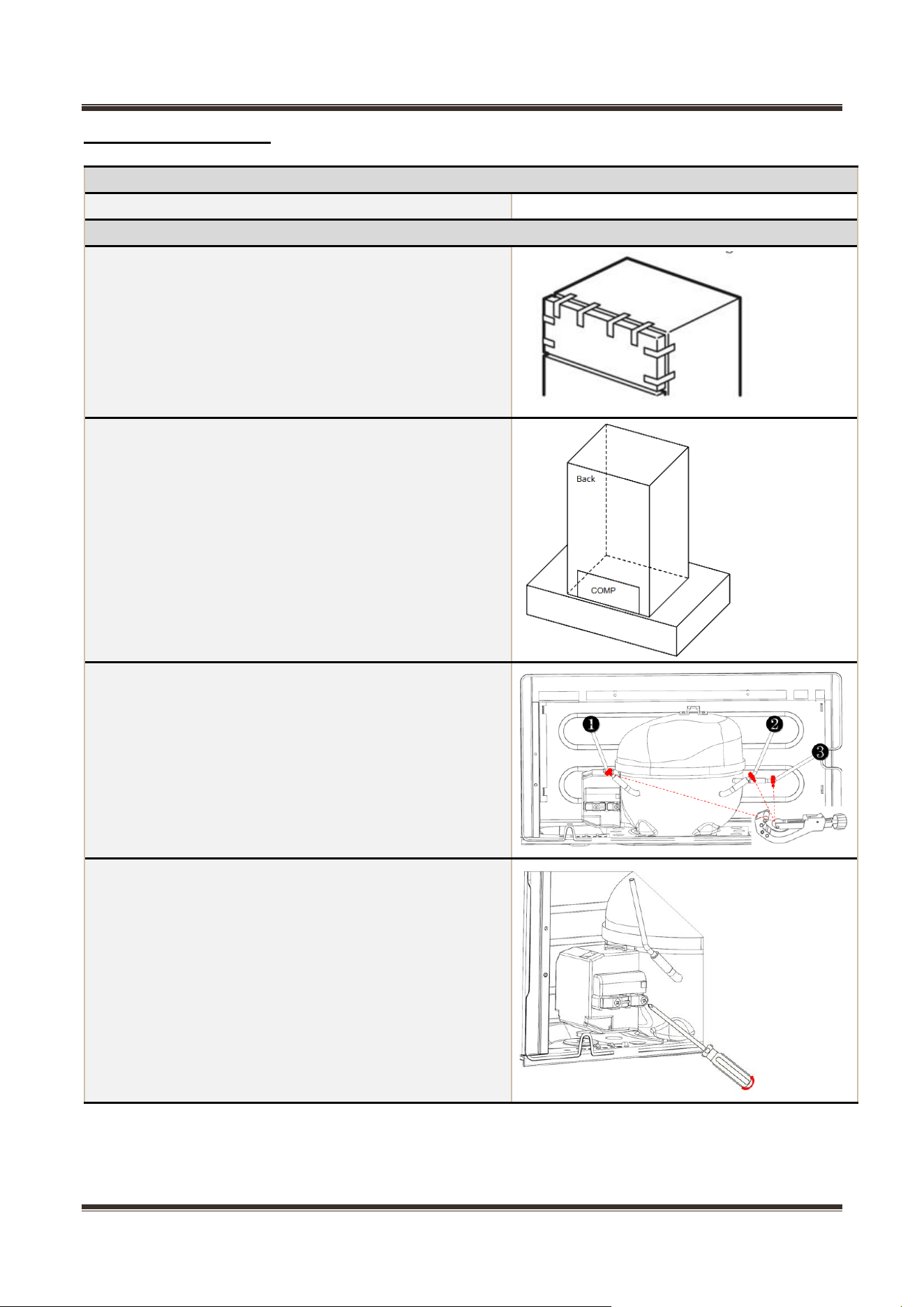
Compressor and the cooling system pipe
1)Cut off the power, remove the goods in the
refrigerator, with the tape to make the door fixed firmly
and prevent the door dropping when the refrigerator
dumping.
2)Place the refrigerator in an area that is open,
ventilated, and away from fire sources. Then placing on
an operating table and securing it firmly.
3)Cut off the compressor pipeline.
-❶ Cut off the process pipeline.
-❷ Cut off the low-pressure muffler.
-❸ Cut off the high-pressure exhaust pipe.
4-1)Remove the screws (for some models)
- One screws outside
- One screw inside
Service Manual_
31
4-2)Remove the metal clamp (for some models)
- Disassembly the metal clamp that is fix the electric
appliance shield
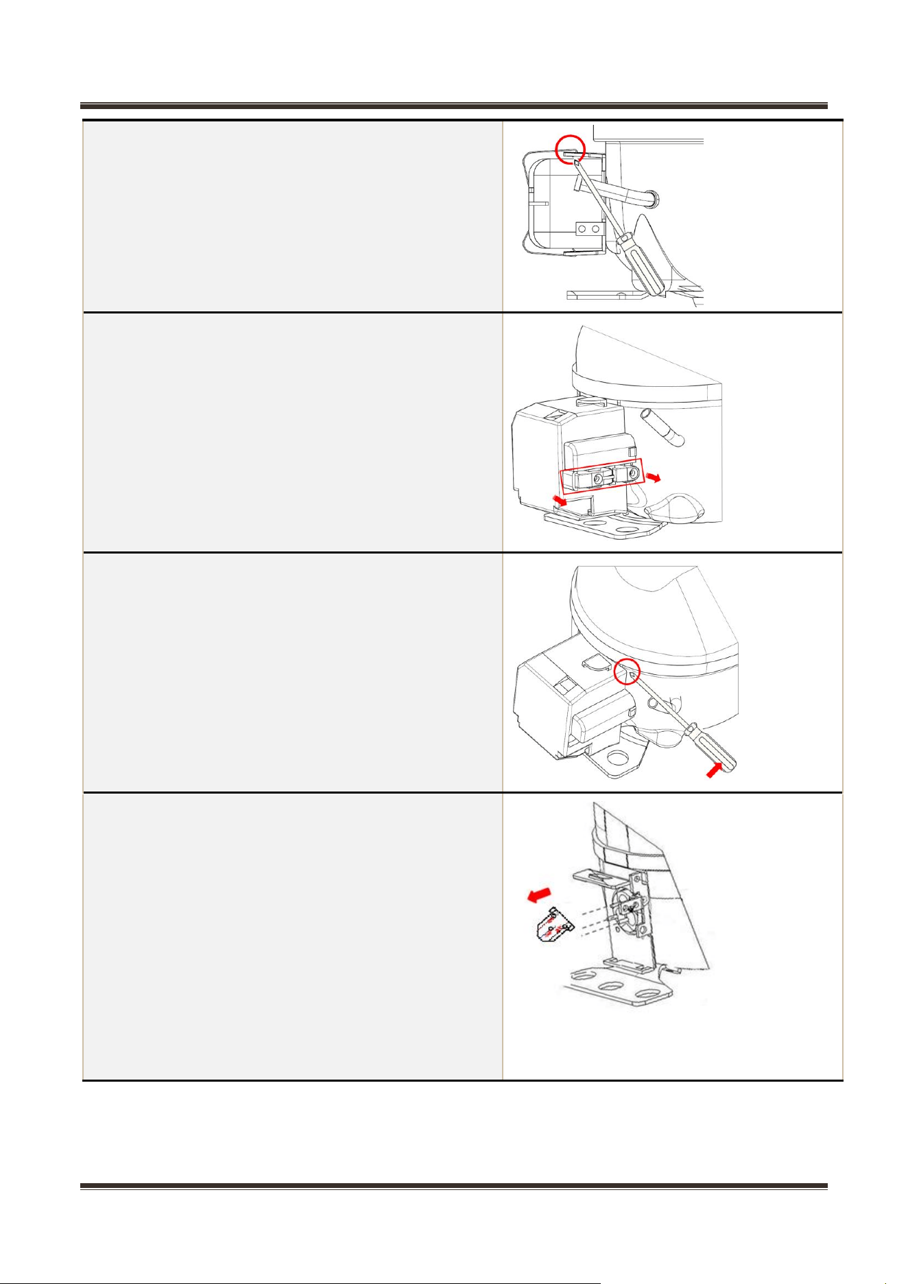
5)Remove the clipping strip
Slowly pull it out
6)Remove the protective cover
- Pry the protective cover slowly from the upper part,
- Pull it out and remove it.
7)Remove the connecting terminals
Unplug the connection terminals of a compressor. (You
can use a screwdriver to pry it slowly)
Service Manual_
32
8)Loosen the screw of the compressor bottom plate,
remove the floor together with the compressor from the
box.
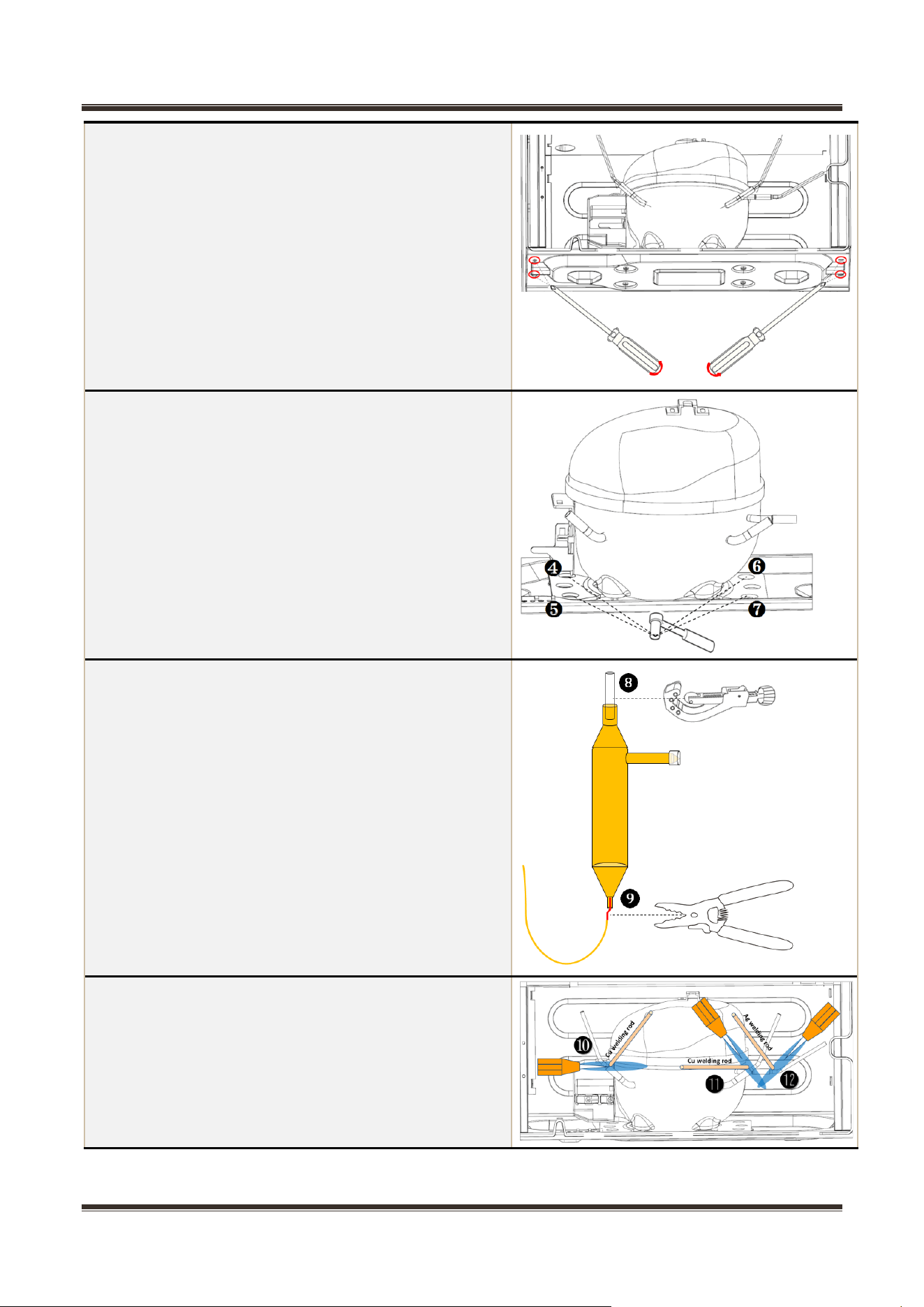
9)Use the wrench to remove the bolts by
steps❹❺❻❼, replace the compressor and reverse
process can complete installation.
10)Use Pipe cutter cut off the condenser tube❽, then
Shear off capillary ❾ by the capillary tube scissors.
11)Replace the compressor and welding the
compressor pipeline.
-❿ Welding the process pipeline.
-⓫Welding the low-pressure muffler.
-⓬Welding the high-pressure exhaust pipe.
Service Manual_
33
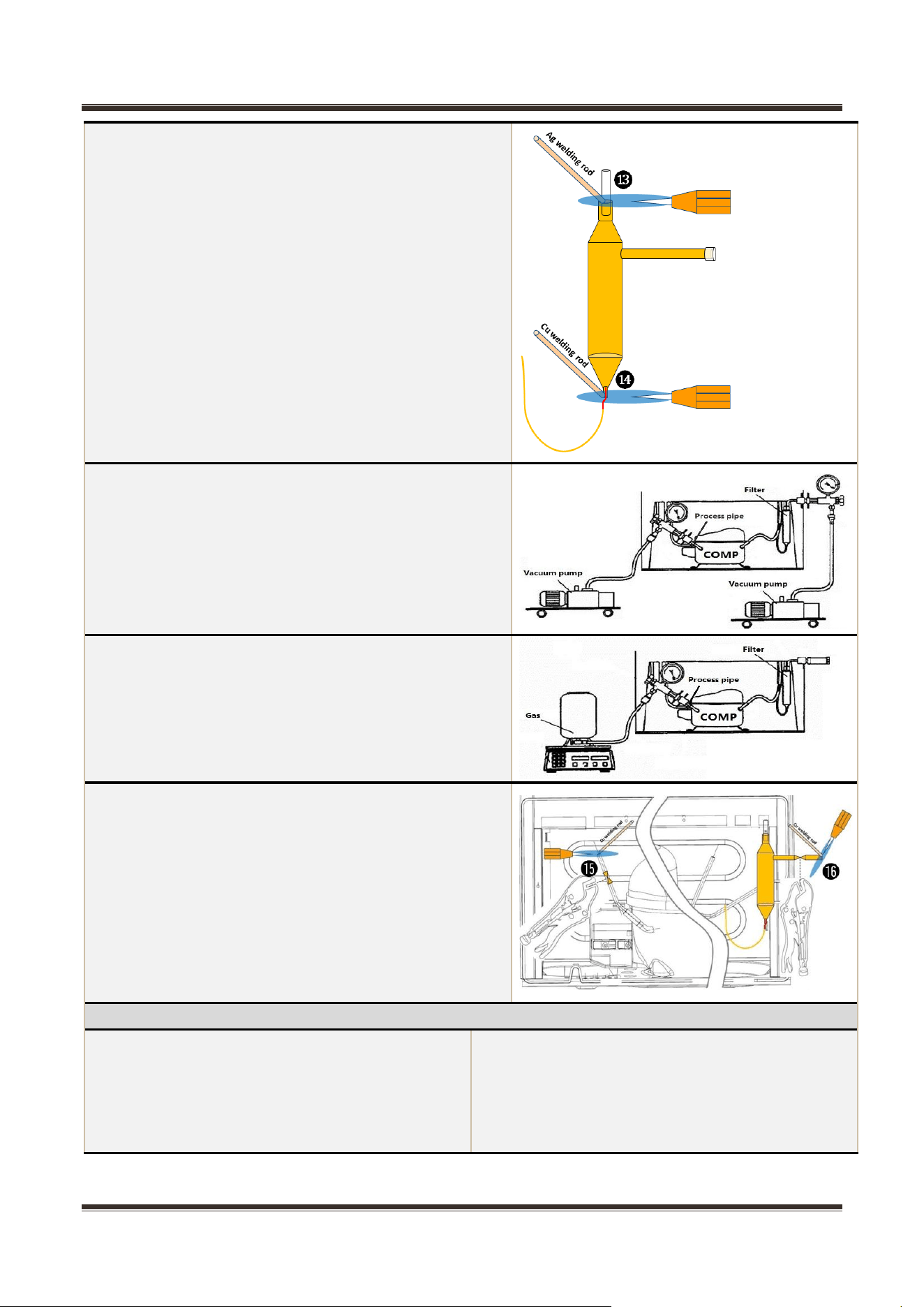
12)Replace the filter, Cu-Fe tubes welding ⓭ used Ag
welding rod, Cu-Cu tubes welding⓮ used Cu welding
rod.
13)Vacuum system,The degree of vacuum below 6Pa.
14)Perfusion refrigerant.
15)Use the vise grip pliers clamp the middle of the
process pipe, then seal welding process tube⓯⓰.
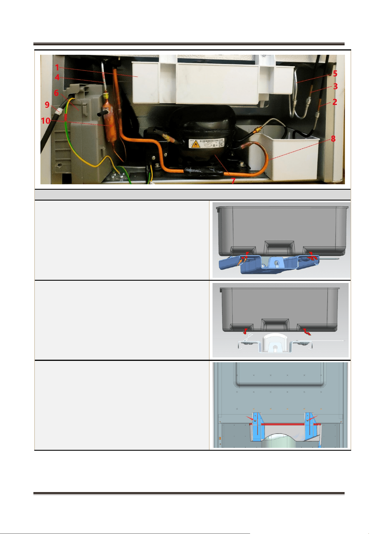
Piping system in the compressor case
❶. Drain tray
❷. condenser(enter)
❸. condenser(exit)
❹. anti-dew tupe assembly(exit)
❺. anti-dew tupe assembly(enter)
❻. main control board box assembly
❼. compressor
❽. suction transition tube
❾. Power wire
❿. dry filter
Service Manual_
34
Drain tray
1)Disengage the drain tray buckle out of the
compressor bottom plate installation hole.
2)Replace the drain tray, the reverse process can
complete installation.
3)Remove the screws from the back of cabinet
assembly
Service Manual_
35
4)Replace the drain tray, the reverse process can
complete installation.
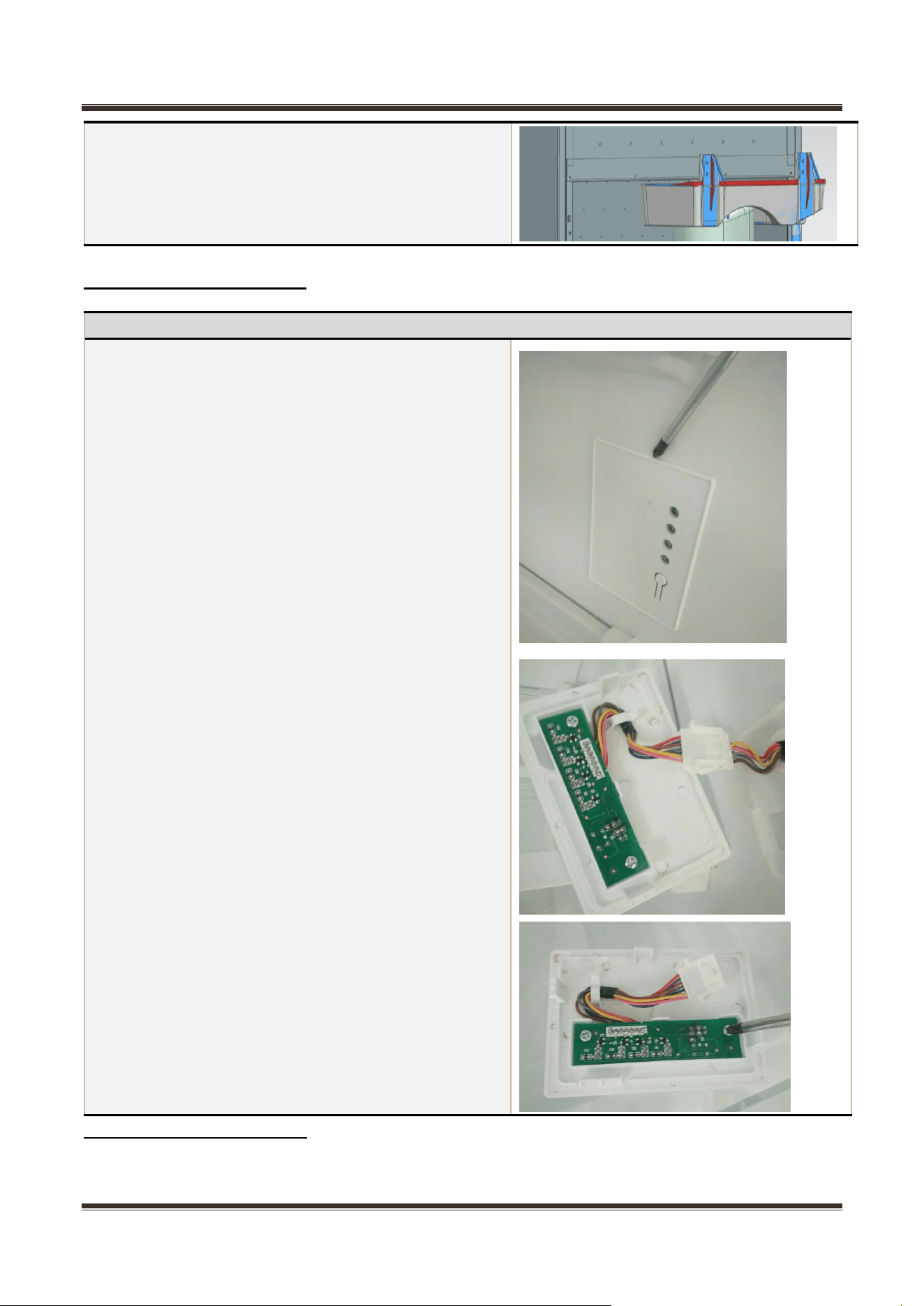
7.8 Display control board
Display control board
1) Pry open the buckle of the display control board
installation box with a straight screwdriver
2) Pull all connector terminals out;
3) Remove 2 screws using a cross screwdriver to
remove the display control board;
4) Replace the master control board in reverse
steps;
Service Manual_
36
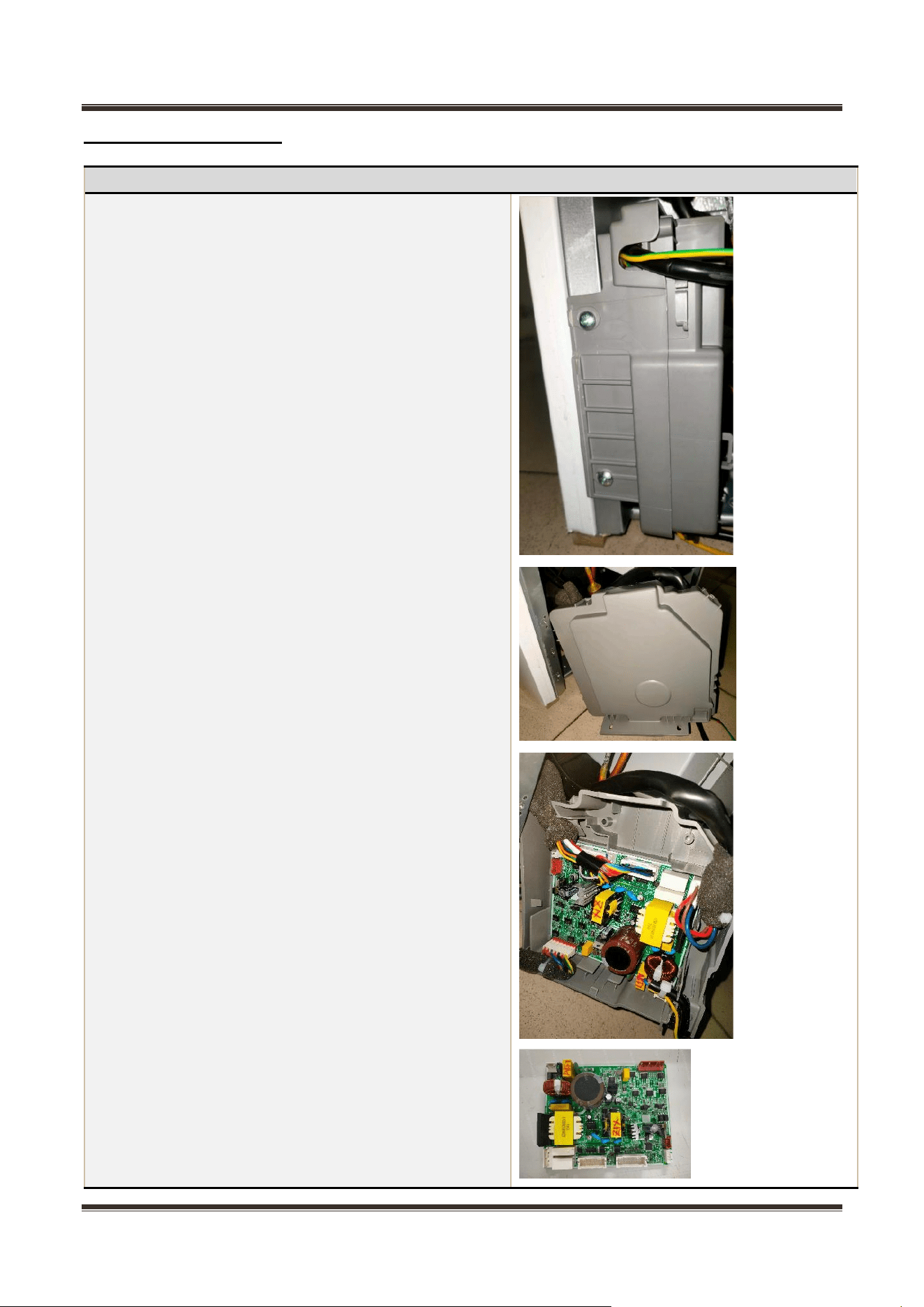
7.9 Main control board
Main control board
1) The main control board box is located compressor
case
2) Remove 2 screws using a cross screwdriver
3) Pry open the buckle of the main control board
installation box with a straight screwdriver
4) Pull all connector terminals out and then remove
the main control board
5) Replace the master control board in reverse
steps.
Service Manual_
37
8. Temperature sensing system
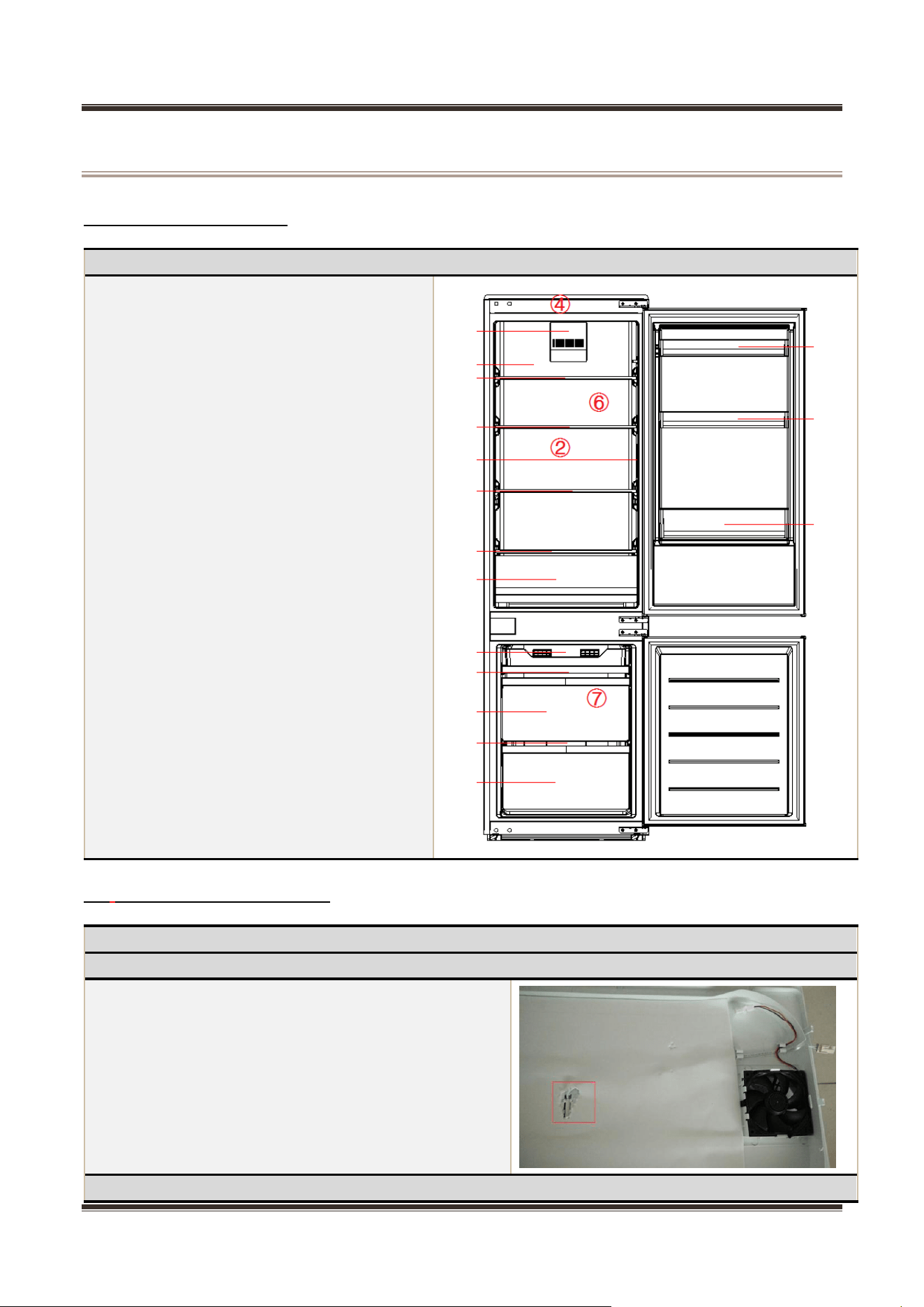
8.1 Position of sensors
8.2 Replacement of sensors
Position of sensors
Have 4 sensors
②Sensor in refrigerating chamber
④Ambient temperature or humidity sensor
⑥Defrost sensor in refrigerating chamber
⑦Defrost sensor freezing chamber
Sensor
Sensor in refrigerating chamber
Before remove the sensor, the refrigerating duct
assembly should be removed
1) Remove the air duct assembly from the
refrigerating.
2) Remove the sensor.
Defrost sensor in refrigerating chamber
Service Manual_
38
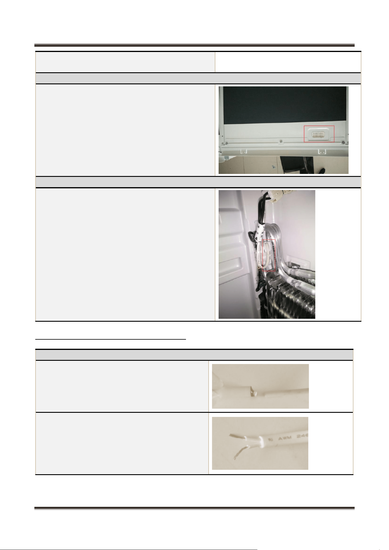
8.3 Sensor without terminal replacement
The defrost sensor of the refrigerator is placed inside the
foam layer and cannot be removed.
Ambient temperature sensor
Sensor position in the upper of the box
化霜传感器 Defrost sensor
The defrost sensor is located on top of the evaporator.
1) Disconnect the connector of defrost sensor
2) Cut off the band which fixes the sensor.
3) Separate the sensor and the evaporator.
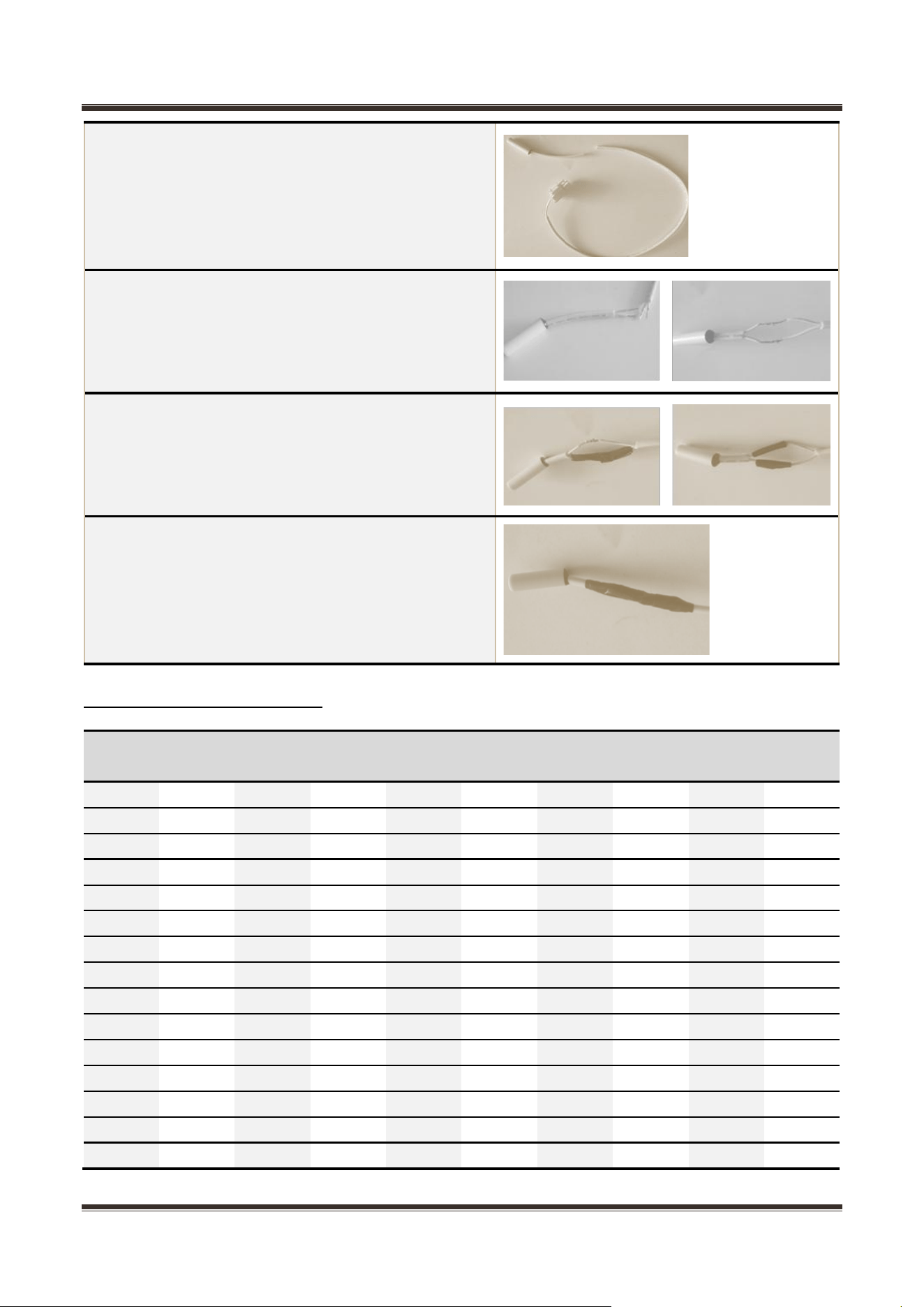
Sensor replacement guidelines
Cut off the damaged head of sensor.
Strip off the sensor wiring.
Service Manual_
39
8.4 Sensor resistance (R/T)
Tx(℃)
R
(KΩ)
Tx(℃)
R
(KΩ)
Tx(℃)
R
(KΩ)
Tx(℃)
R
(KΩ)
Tx(℃)
R
(KΩ)
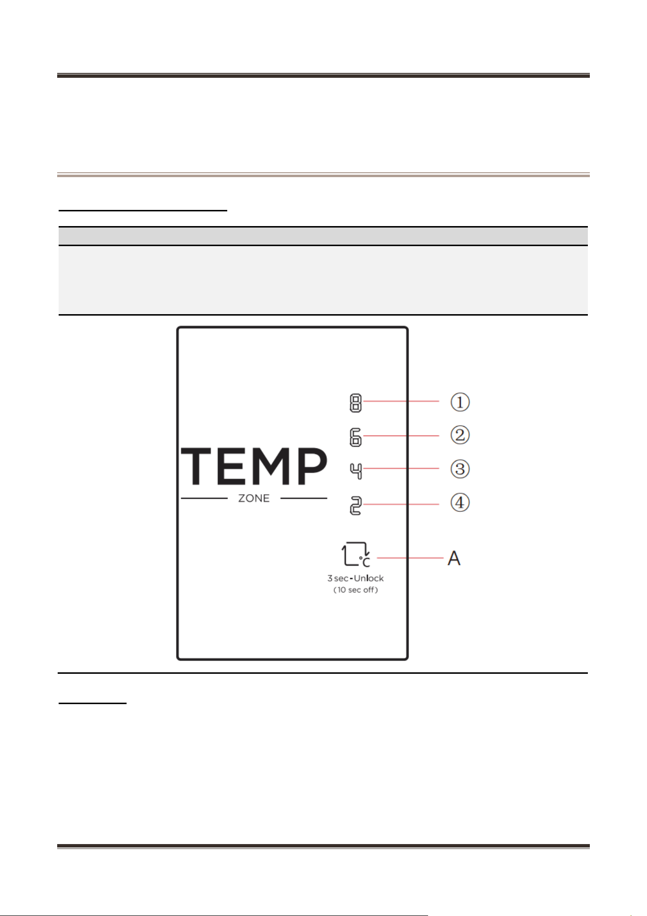
-30
33.81
-15
14.31
0
6.495
15
3.141
30
1.617
-29
31.85
-14
13.55
1
6.175
16
2.999
31
1.55
-28
30.01
-13
12.83
2
5.873
17
2.865
32
1.486
-27
28.29
-12
12.16
3
5.587
18
2.737
33
1.426
-26
26.68
-11
11.52
4
5.315
19
2.616
34
1.368
-25
25.17
-10
10.92
5
5.06
20
2.501
35
1.312
-24
23.76
-9
10.35
6
4.818
21
2.391
36
1.259
-23
22.43
-8
9.82
7
4.589
22
2.287
37
1.209
-22
21.18
-7
9.316
8
4.372
23
2.188
38
1.161
-21
20.01
-6
8.841
9
4.167
24
2.094
39
1.115
-20
18.9
-5
8.392
10
3.972
25
2.005
40
1.071
-19
17.87
-4
7.968
11
3.788
26
1.919
41
1.029
-18
16.9
-3
7.568
12
3.613
27
1.838
42
0.9885
-17
15.98
-2
7.19
13
3.447
28
1.761
43
0.9506
-16
15.12
-1
6.833
14
3.29
29
1.687
44
0.914
Take out a new sensor to cut the head of sensor.
(Spare parts code:11201007000795) Its technical
specifications apply to all MIDEA refrigerators.
Strip off the head of the sensor and connect it.
Wrap the two wires together with insulation tape.
Wrap the two wires together.
Service Manual_
40
9. Function and operation
9.1 Display operation panel
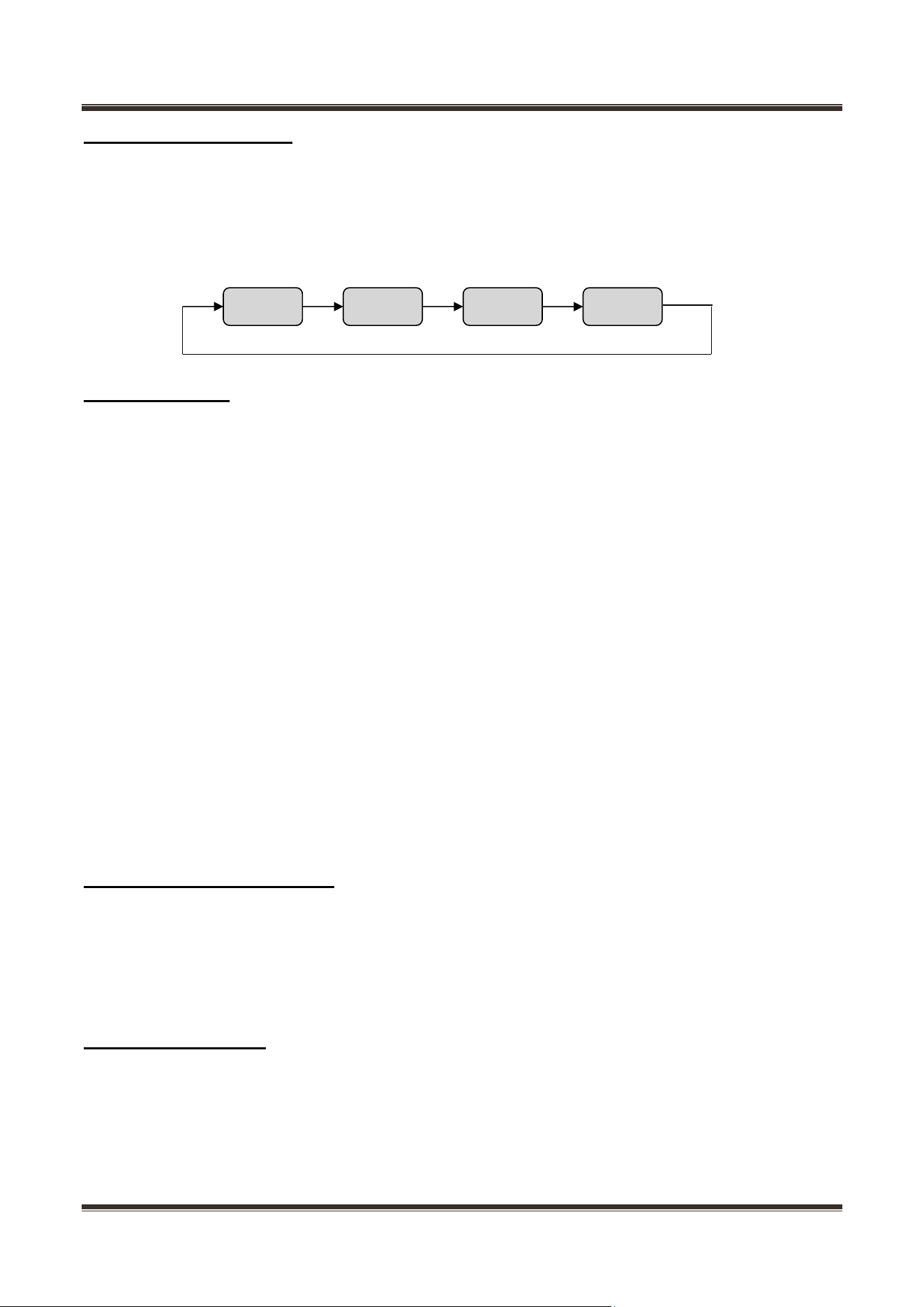
Icons
Button
❶ One gear
❷ Two gear
❸ Three gear
❹ Four gear
A Gear set button
9.2 Display
At the first time of power-on, the display screen will be bright for 3 seconds and then according to the three
gear to show operation
Normal operation display:
1)When failure occurs, the corresponding LED light group will display fault code (circular display);
2)If no failure occurs, the current operation gear will be displayed.
Service Manual_
41
9.3 Temperature setting
Unlock the display control panel first by pressing the gear setting button A for 3 seconds. Then press
the button A once, the gear will be changed once, 30 seconds after setting, the refrigerator will be
running in accordance with the set value.
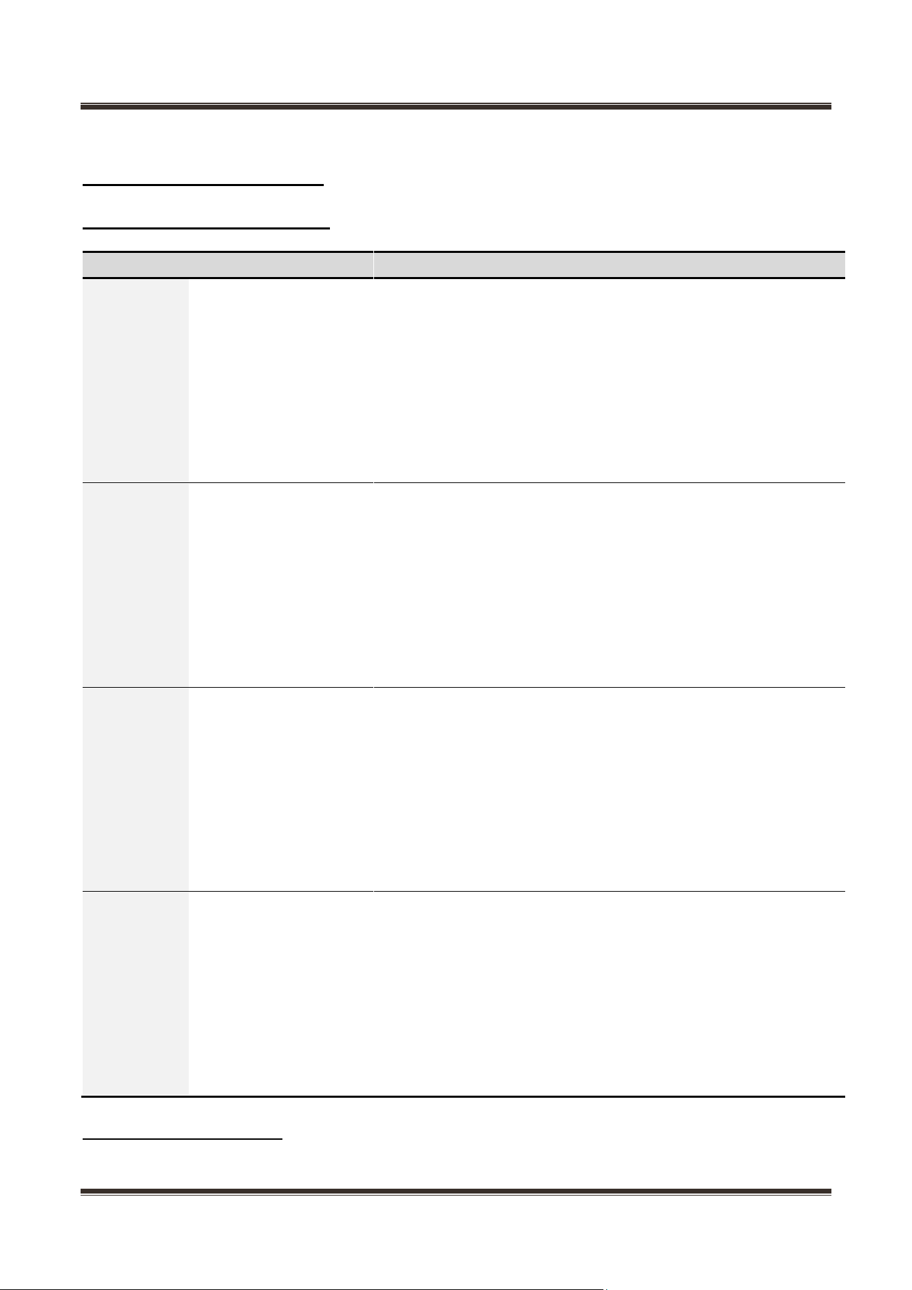
The gear can be set to: (Setting the gear from one to four the set temperature will be lower to higher
and it can be set circularly)
9.4 Mode setting
9.4.1 Super cooling mode
Unlock the display control panel first by pressing the gear setting button A for 3 seconds. Then
press the button A for 3 seconds to enter the super cooling mode. The temperature of the
refrigeration room is adjusted to 2℃.
Then press the button A once to exit the super cooling mode or automatically exit the super cooling
mode after 6h.
9.4.2 Super freezing mode
Unlock the display control panel first by pressing the gear setting button A for 3 seconds. Then
press the button A for 6 seconds to enter the super freezing mode. The temperature of the freezer
room is adjusted to -24℃.
Then press the button A once to exit the super freezing mode or automatically exit the super freezing
mode after 40h.
9.4.3 Standby mode
Unlock the display control panel first by pressing the gear setting button A for 3 seconds. Then
press the button A for 10 seconds, the display screen goes off and the standby mode is entered after
30 seconds of releasing the button.
Then press the button A once to exit the standby mode.
9.4 lock and unlock Settings
In the lock state, long press the SET key for 3 seconds to unlock the device before it can operate. When
the unlock is effective, all LED lights will flash for 2 times. In the lock state, all LED lights will flash for 2 s
econds to remind the user to unlock the device first.
In the unlocking state, no operation of the button for 30 seconds will automatically lock, no manual lock.
9.5 memory function
Power off memory function of the control device, memory contents:
Refrigerator setting temperature: set the gear
Standby mode
Super freezing mode
Press total run time (when power on freezing frost sensor temperature greater than 8 ℃, press total run ti
2℃
4℃
6℃
8℃
Service Manual_
42
me).
9.6 Open door alarm (None)
9.7 Fault code and solutions
Fault code
Display
Failure Type
Solution
E1
LED1 (8℃) flashing
Temperature
sensor fault in
refrigerating
chamber
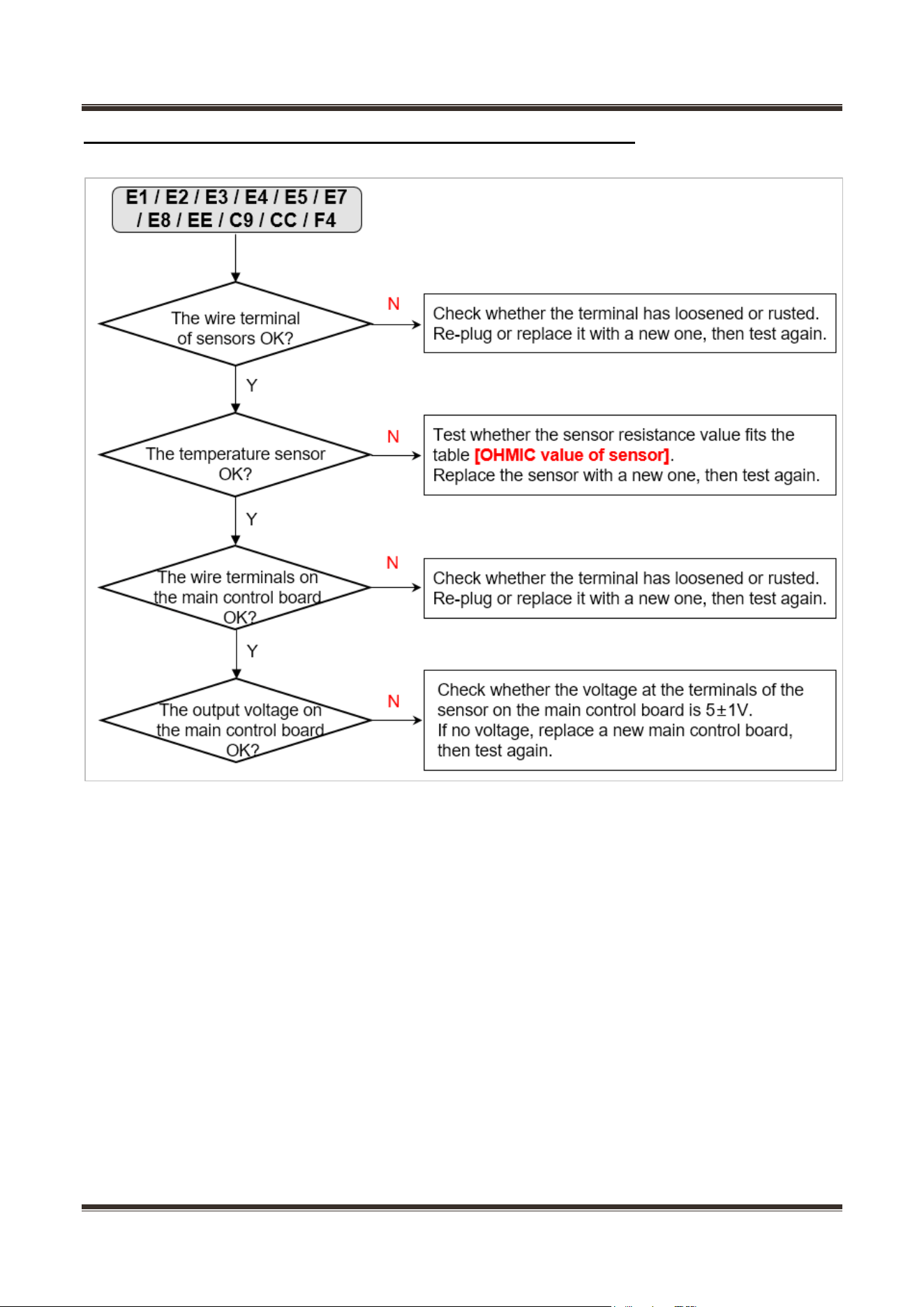
Step 1: Check whether the terminal CN8 is
well stuck, pull out the terminal and re-stick it
in place
Step 2: Check to see if there are foreign
matters on the terminal. Pull out the
refrigerating sensor according to the method
in described in Article 8.5 and then inspect the
sensor against the resistance value table in
10.8.
Step 3: Replace main control board
Step 4: Replace electrical wiring main harness
E4
LED2 (6℃) flashing
Fault of R
defrost sensor
Step 1: Check whether the terminal CN8 is
well stuck, pull out the terminal and re-stick it
in place
Step 2: Check to see if there are foreign
matters on the terminal. Pull out the
refrigerating sensor according to the method
in described in Article 8.5 and then inspect the
sensor against the resistance value table in
10.8.
Step 3: Replace main control board
Step 4: Replace electrical wiring main harness
E5
LED3 (4℃) flashing
Fault of F
defrost sensor
Step 1: Check whether the terminal CN8 is
well stuck, pull out the terminal and re-stick it
in place
Step 2: Check to see if there are foreign
matters on the terminal. Pull out the defrost
sensor in freezing chamber according to the
method in described in Article 8.5 and then
inspect the sensor against the resistance
value table in 10.8.
Step 3: Replace main control board
Step 4: Replace electrical wiring main harness
E7
LED4 (2℃) flashing
Ambient
temperature
sensor fault
Step 1: Check whether the terminal CN8 of
main control board is well stuck, pull out the
terminal and re-stick it in place
Step 2: Check to see if there’re foreign
matters on the terminal. Pull out the defrost
sensor in freezing chamber according to the
method in described in Article 8.5 and then
inspect the sensor against the resistance
value table in 10.8.
Step 3: Replace main control board
Step 4: Replace electrical wiring main harness
9.8 Defrosting function
1. Defrost the freezing chamber as per the accumulative operation time of the Compressor
Service Manual_
43
2. If power failure occurs abruptly to the Compressor and the defrosting sensor in freezing chamber is less
than 0℃ after powering on, then first conduct defrosting once. If more than 0℃, then defrosting is not
needed.
After that, conduct defrosting according to using condition and ambient temperature in a period between
6 and 24 hours as per the accumulative operation time of the Compressor.
9.9 Test mode
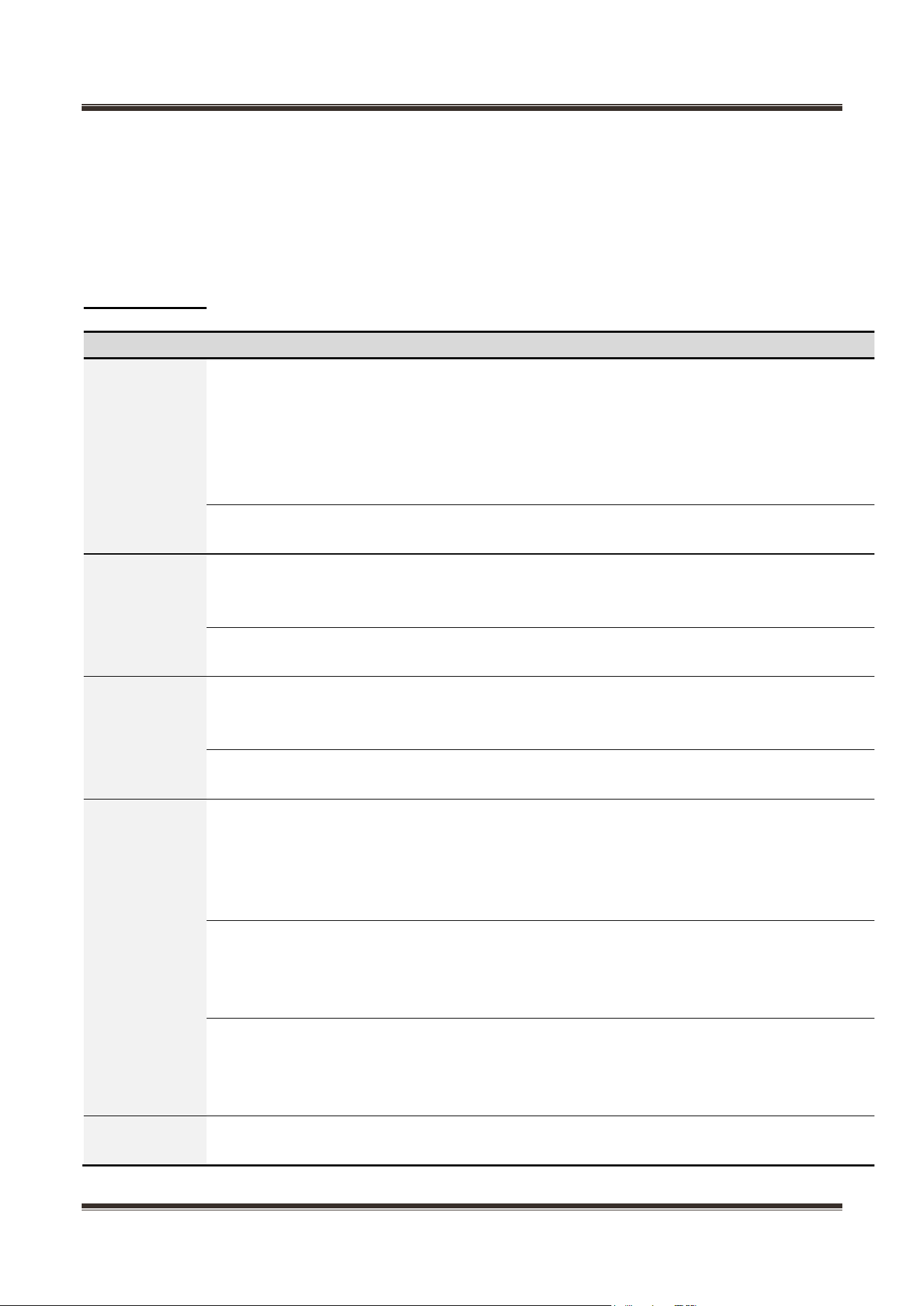
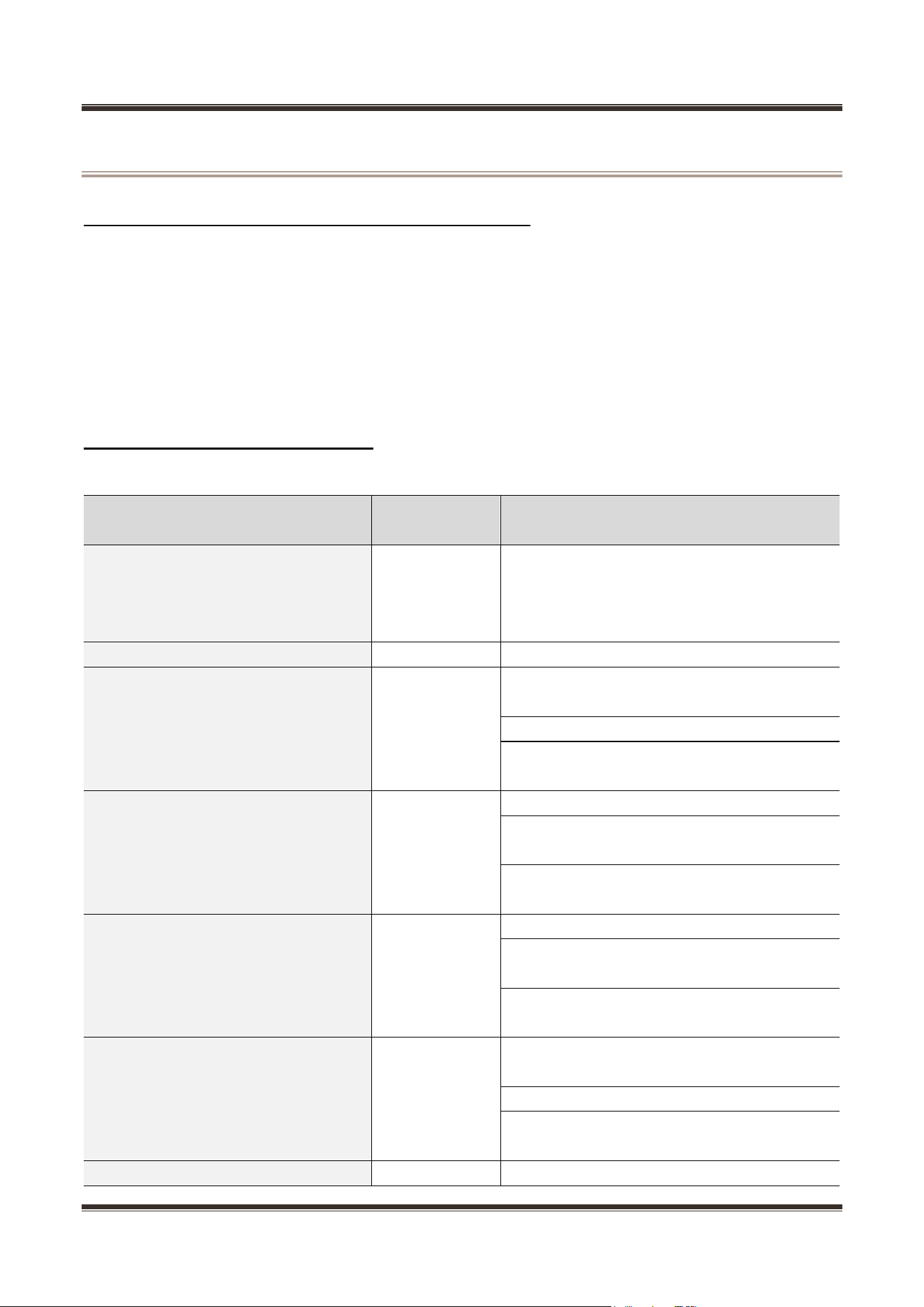
Test items
Testing Method
Expected result
Enter Test
Mode
The LED lights indicate ON means
changing it to flashing mode after press
“SET” key 20s under the condition of
temperature adjustment. After that, press
“SET” key 7s to enter to forced operation
mode.
The refrigerator enters into testing mode
when the LED lights are off
After entering into test mode, if no button
is pressed within 25 seconds
then the refrigerator will exit the test mode
and return to normal operation mode
Select to
enter into
forced cooling
mode
Enter into test mode and press button for
the second time
LED indicators on Gear 1, 2 light up and
other LED indicators light off, then the
compressor and the fan will start working
In forced cooling mode, if no button is
pressed within 72 hours,
then the refrigerator will exit the test mode
and return to normal operation mode
Select to
enter into
forced
compensating
heating mode
Enter into test mode and press button for
the first time
LED indicators on Gear 3, 4 light up and
other LED indicators light off, then the
compensating heater will start working
In forced heating wire mode, there has
been no button operation for 20 hours.
then the refrigerator will exit the test mode
and return to normal operation mode
Select to
enter into
forced
defrosting
mode
Enter into test mode and press button for
the third time
LED indicators on Gear 1, 4 light up and
other LED indicators light on, then the
compressor and the fan will stop working,
The heater open, refrigerator into forced
frost
In forced defrosting mode, when the
defrosting sensor reach a temperature of
8°C and the defrosting heater has been
working for 2 minutes,
then the refrigerator will exit the test mode
and return to normal operation mode
In forced defrosting mode, if the
temperature of defrosting sensor is
always lower than 8°C and the defrosting
heater has been working for 1 hour,
then the refrigerator will exit the test mode
and return to normal operation mode
Exit the test
mode
Enter into test mode and press button for
the third time
then the refrigerator will exit the test mode
and return to normal operation mode
Service Manual_
44
10. Compressor
10.1 Compressor on and off Control specifications
1.1 When one of the following conditions is met, the compressor stops:
1) Tr ≤ Trt;
2) The compressor runs continuously for more than 3 hours (Stop 5 minutes);
1.2 When all the following conditions are met, the compressor starts up:
1) Tr ≥Trk;
2) Compressor downtime is more than 5min.
★When 1.1 and 1.2 are not satisfied, the compressor maintains the original state
10.2 Inverter board fault analysis
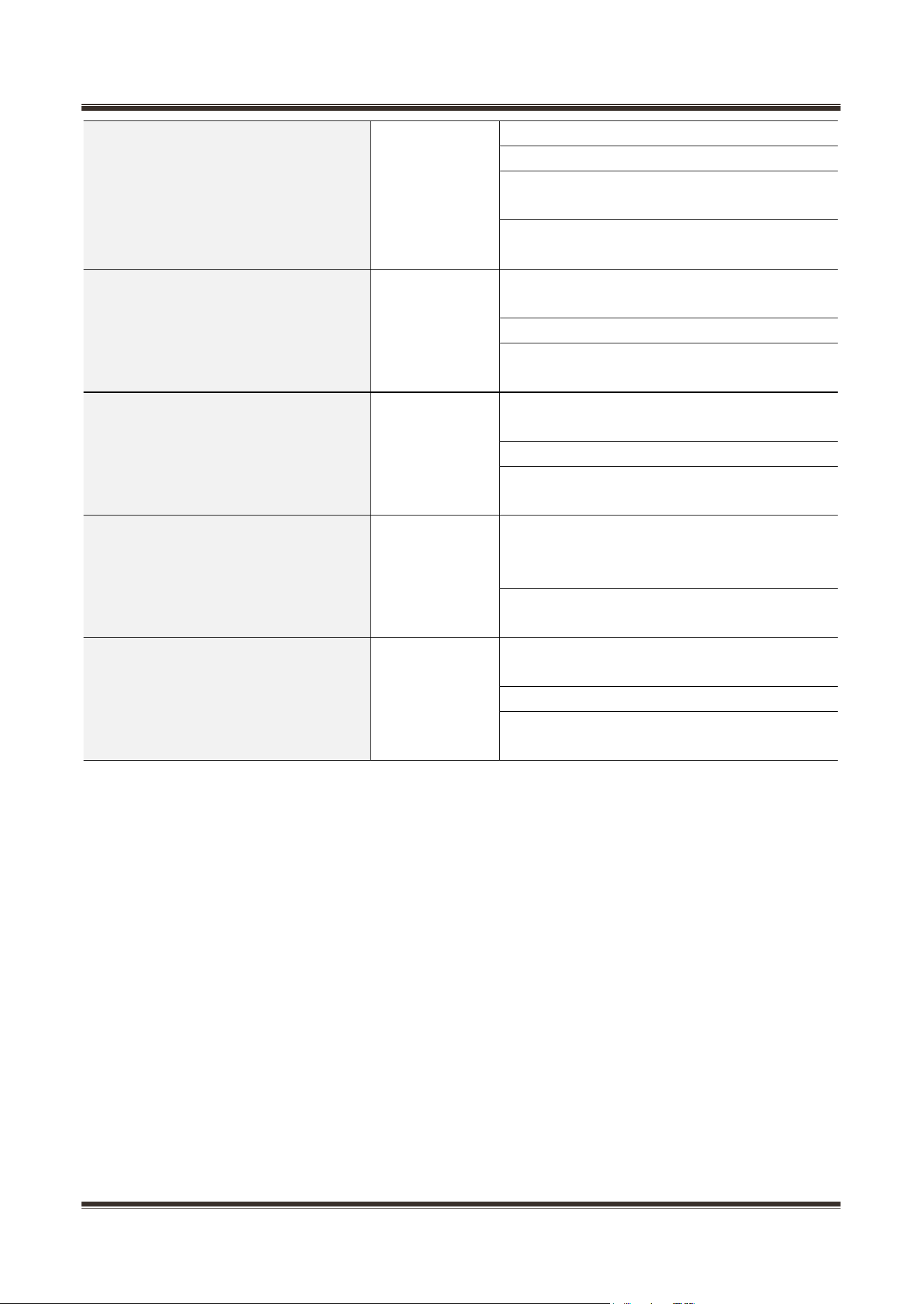
Running status of LED
Fault Type
Troubleshooting and Solutions
The light is always on when the power
is turned on for the first time, and it is
always off after the compressor is
turned on and off
Normal working
\
Not light
Standby
\
Blink once: light 0.5 second,
extinguish 0.5 second, interval
time(extinguish) is 2 second
Software over
current
protection
Step 1: Measure whether the U-V-W
resistance of compressor is same
Step 2: If ok, replace a new inverter board
Step 3: If the fault still occurs, replace a new
compressor
Blink twice: light 0.5 second,
extinguish 0.5 second, interval
time(extinguish) is 2 second
Overvoltage
protection
Measure the voltage between L and N
1 ) If it is less than 260V, replace a new
inverter board
2)If more than 260V, please check the power
supply and power cable
Blink three times: light 0.5 second,
extinguish 0.5 second, interval
time(extinguish) is 2 second
Under voltage
protection
Measure the voltage between L and N
1 ) If it is less than 160V, replace a new
inverter board
2)If more than 160V, please check the power
supply and power cable
Blink four times: light 0.5 second,
extinguish 0.5 second, interval
time(extinguish) is 2 second
Hardware over
current
protection
Step 1: Measure whether the U-V-W
resistance of compressor is same
Step 2: If ok, replace a new inverter board
Step 3: If the fault still occurs, replace a new
compressor
Blink six times: light 0.5 second,
Lack of phase
Step 1: Measure whether the U-V-W
Service Manual_
45
extinguish 0.5 second, interval
time(extinguish) is 2 second
protection
resistance of compressor is same
Step 2: If ok, replace a new inverter board
Step 3: If not same, please check the wiring
connection to compressor
Step 4: If the connection is fine, replace a
new compressor
Blink eight times: light 0.5 second,
extinguish 0.5 second, interval
time(extinguish) is 2 second
Misstep
protection
Step 1: Measure whether the U-V-W
resistance of compressor is same
Step 2: If ok, replace a new inverter board
Step 3: If the fault still occurs, replace a new
compressor
Blink night times: light 0.5 second,
extinguish 0.5 second, interval
time(extinguish) is 2 second
Running block
protection
Step 1: Measure whether the U-V-W
resistance of compressor is same
Step 2: If ok, replace a new inverter board
Step 3: If the fault still occurs, replace a new
compressor
Blink ten times: light 0.5 second,
extinguish 0.5 second, interval
time(extinguish) is 2 second
Overheat
protection
Step 1: Open the inverter board mounting
box, power off for 1 minute and re-power on,
then wait 20 minutes.
Step 2: If the fault still occurs, replace a new
inverter board.
Blink eleven times: light 0.5 second,
extinguish 0.5 second, interval
time(extinguish) is 2 second
Starting failure
Step 1: Measure whether the U-V-W
resistance of compressor is same
Step 2: If ok, replace a new inverter board
Step 3: If the fault still occurs, replace a new
compressor
Service Manual_
46
11. Troubleshooting Method
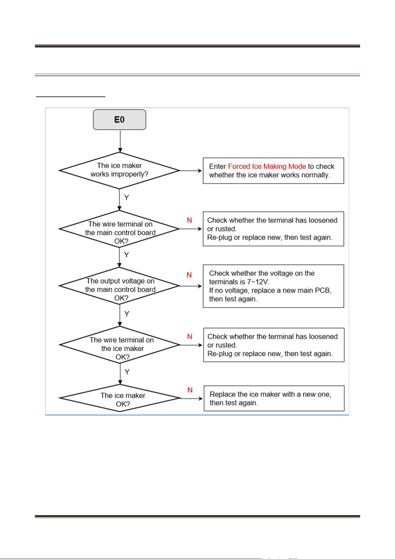
11.1 Error code E0
Service Manual_
47
11.2 Error code E1 / E2 / E3 / E4 / E5 / E7 / E8 / EE / C9 / CC / F4
Service Manual_
48
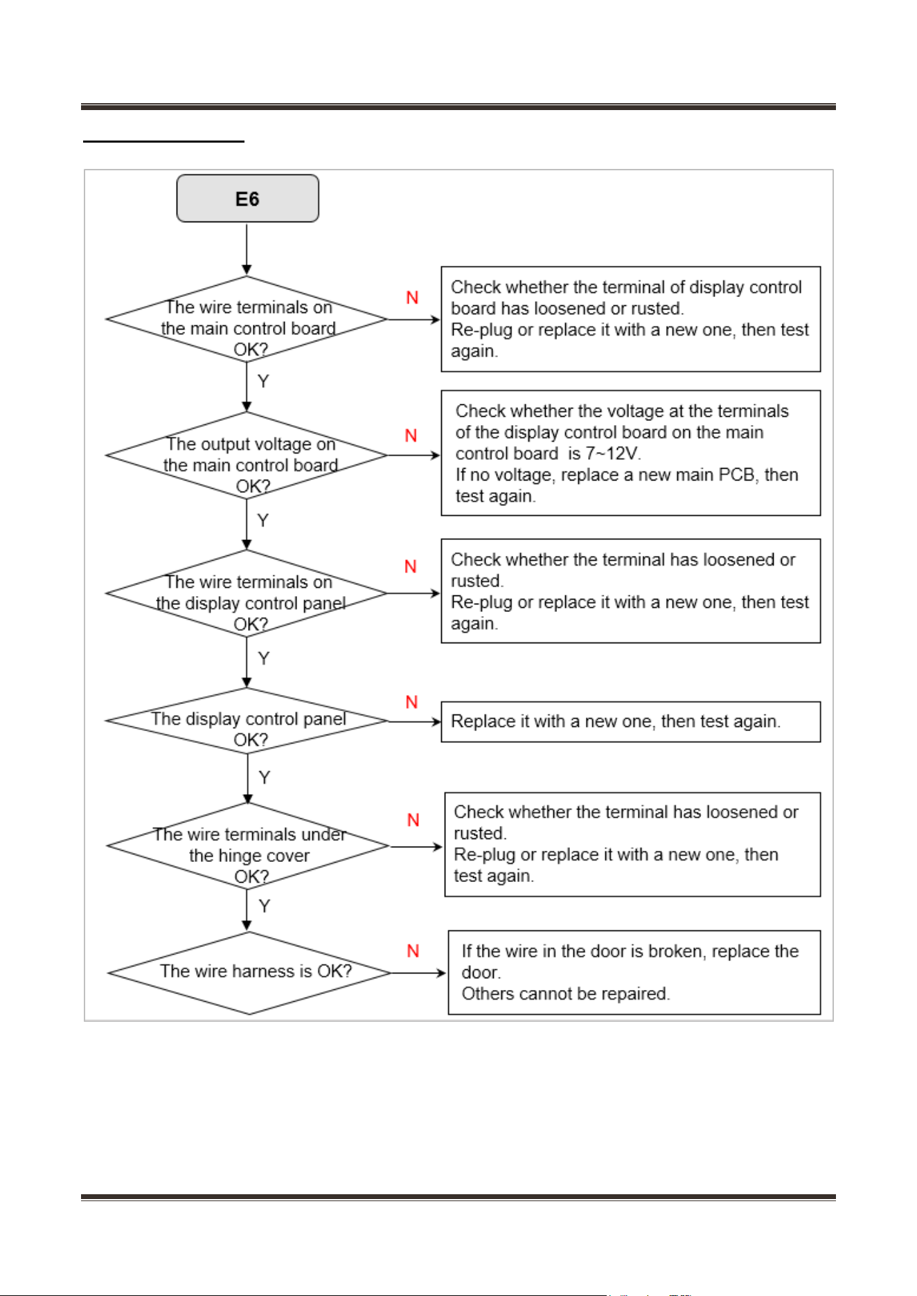
11.3 Error code E6
Service Manual_
49
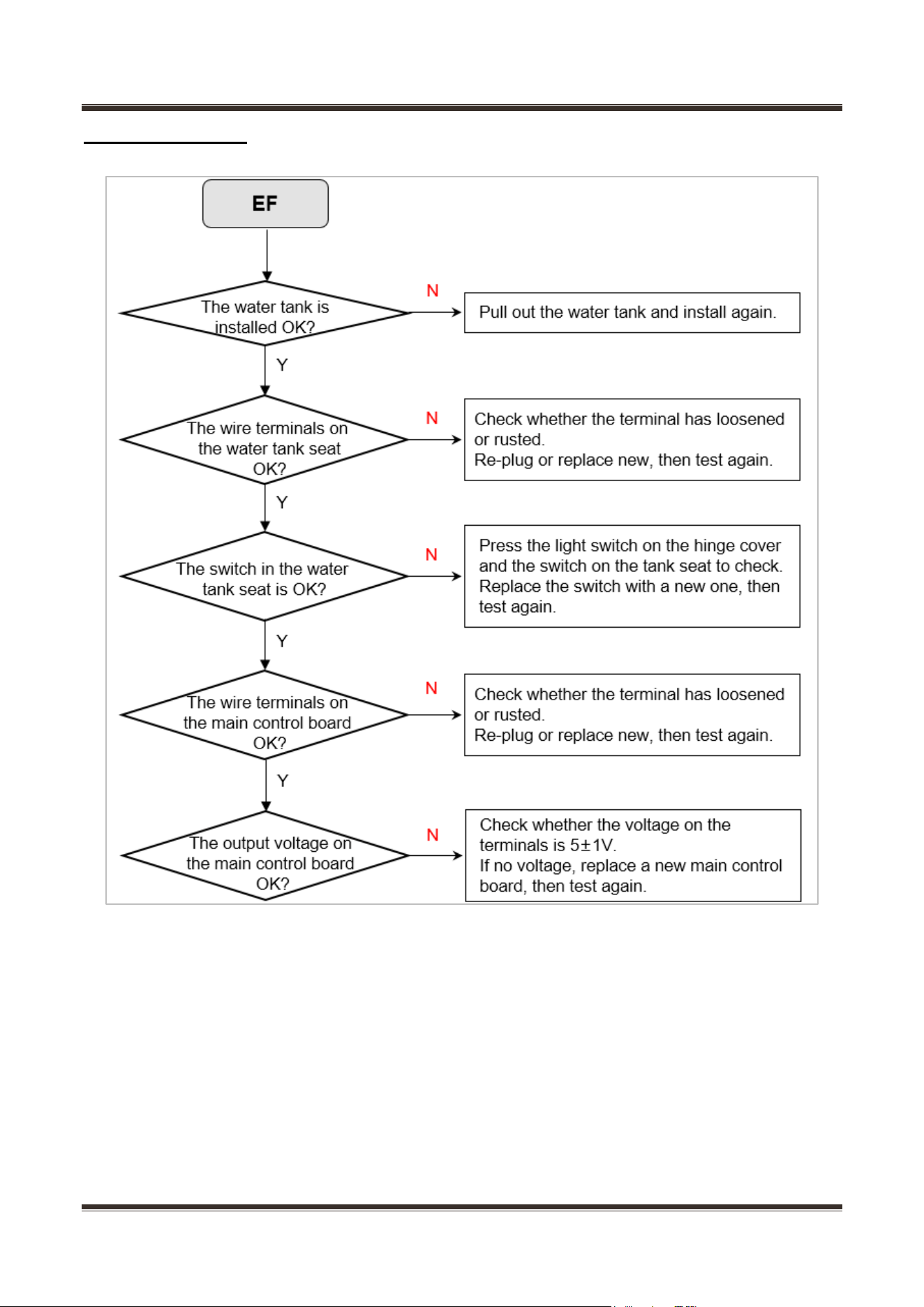
11.4 Error code EF
Service Manual_
50
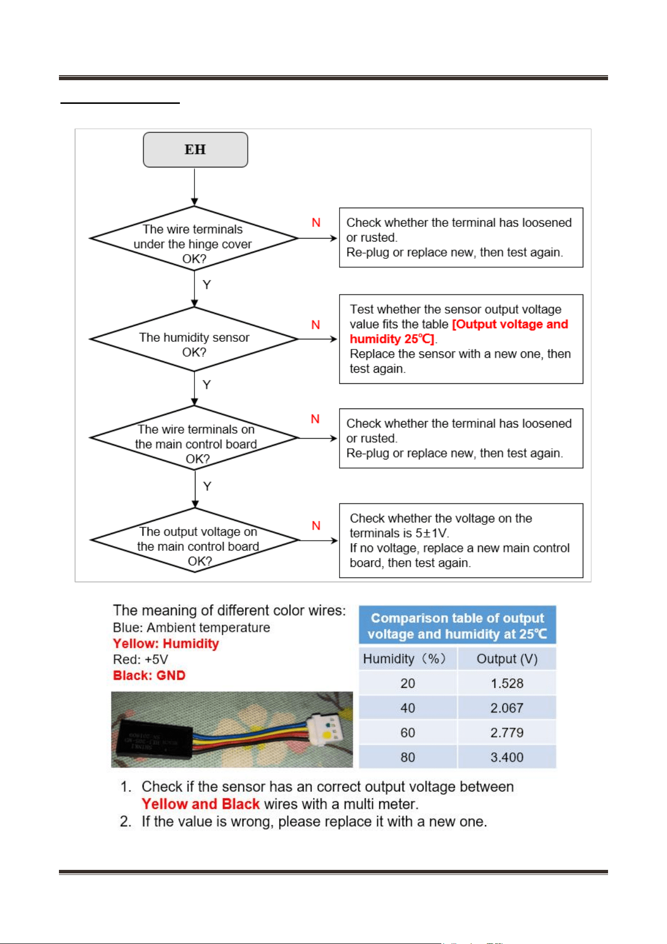
11.5 Error code EH
Service Manual_
51
11.6 Error code EP
Service Manual_
52
11.7 Error code CA
Service Manual_
53
11.8 Not cooling in all the chambers
Service Manual_
54
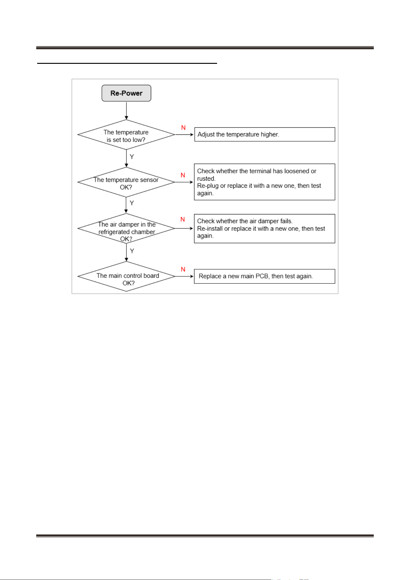
11.9 Poor Cooling in all the chambers
Service Manual_
55
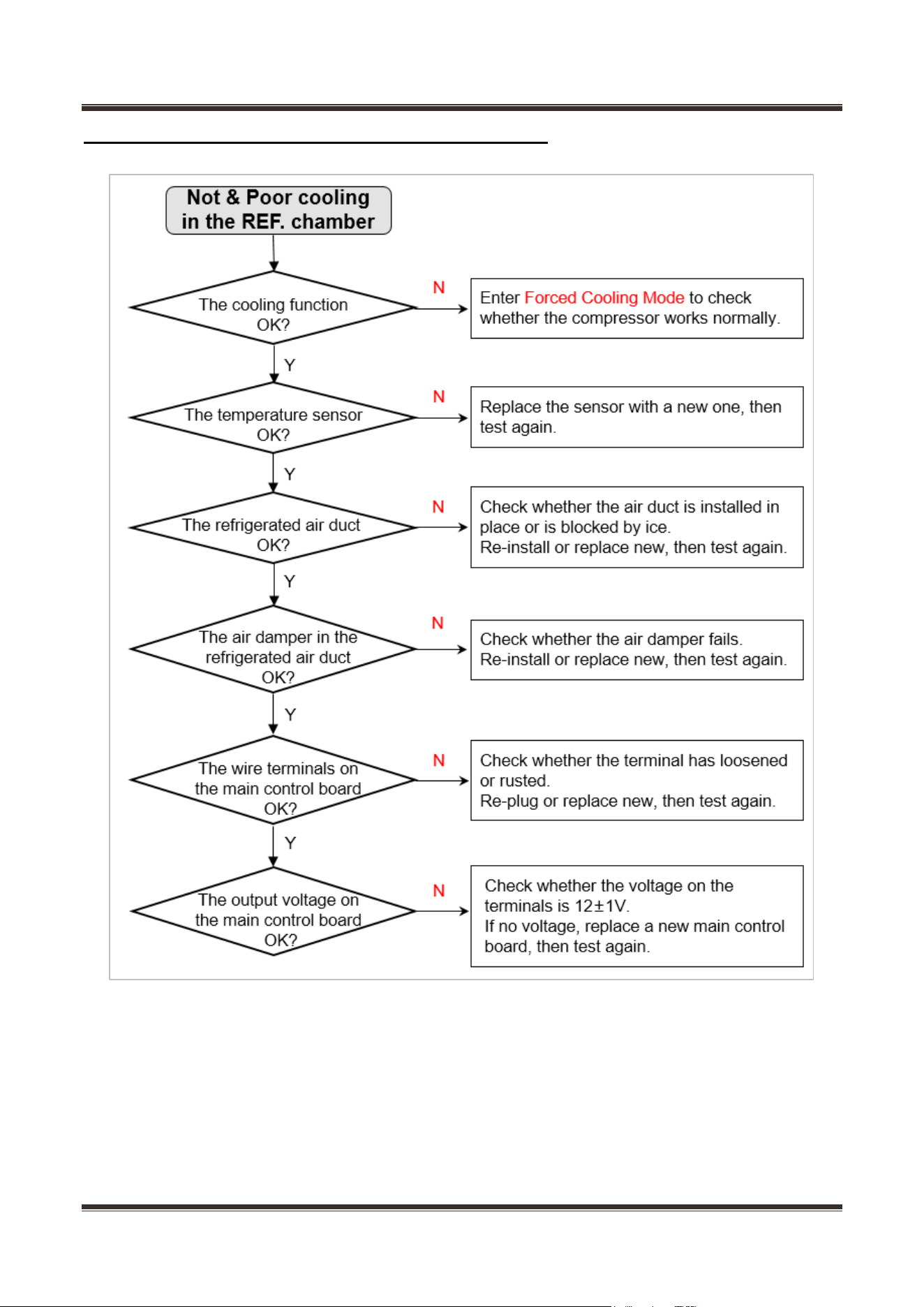
11.10 Overcooling in the refrigerated chamber
Service Manual_
56
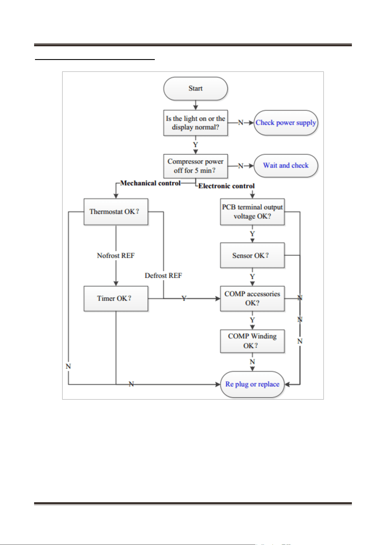
11.11 Not & Poor cooling in the refrigerated chamber
Service Manual_
57
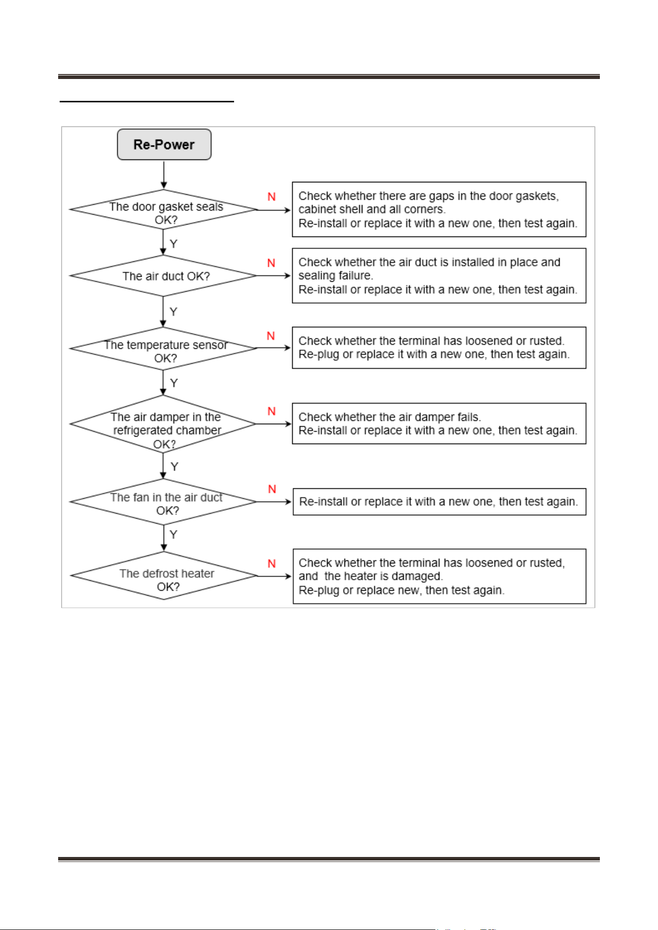
11.12 No working of compressor
Service Manual_
58
11.13 Condensation & Frost
Service Manual_
59
11.14 Display panel failure
Service Manual_
60
11.15 Light failure
Service Manual_
61
11.16 No water from the ice & water dispenser
Service Manual_
62
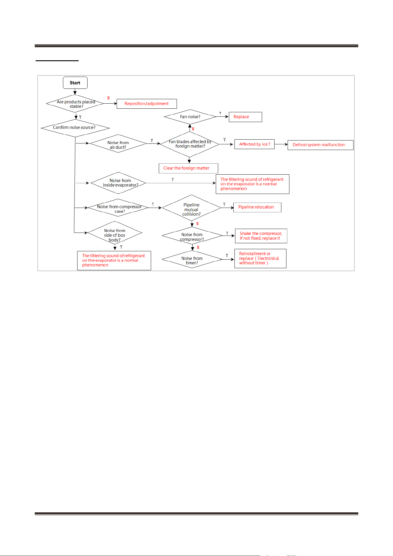
11.17 No ice from the ice & water dispenser
Service Manual_
63
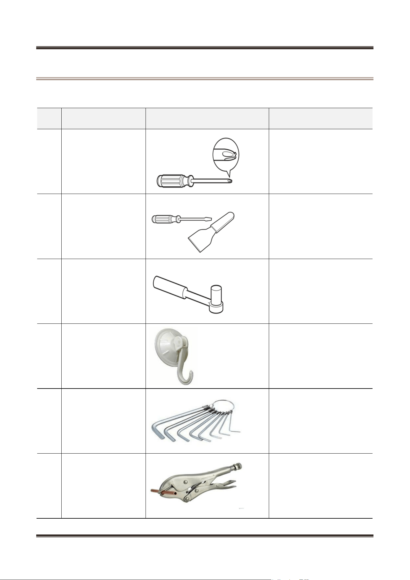
11.18 Noise
Service Manual_
64
12. Maintenance tooling, equipment and material
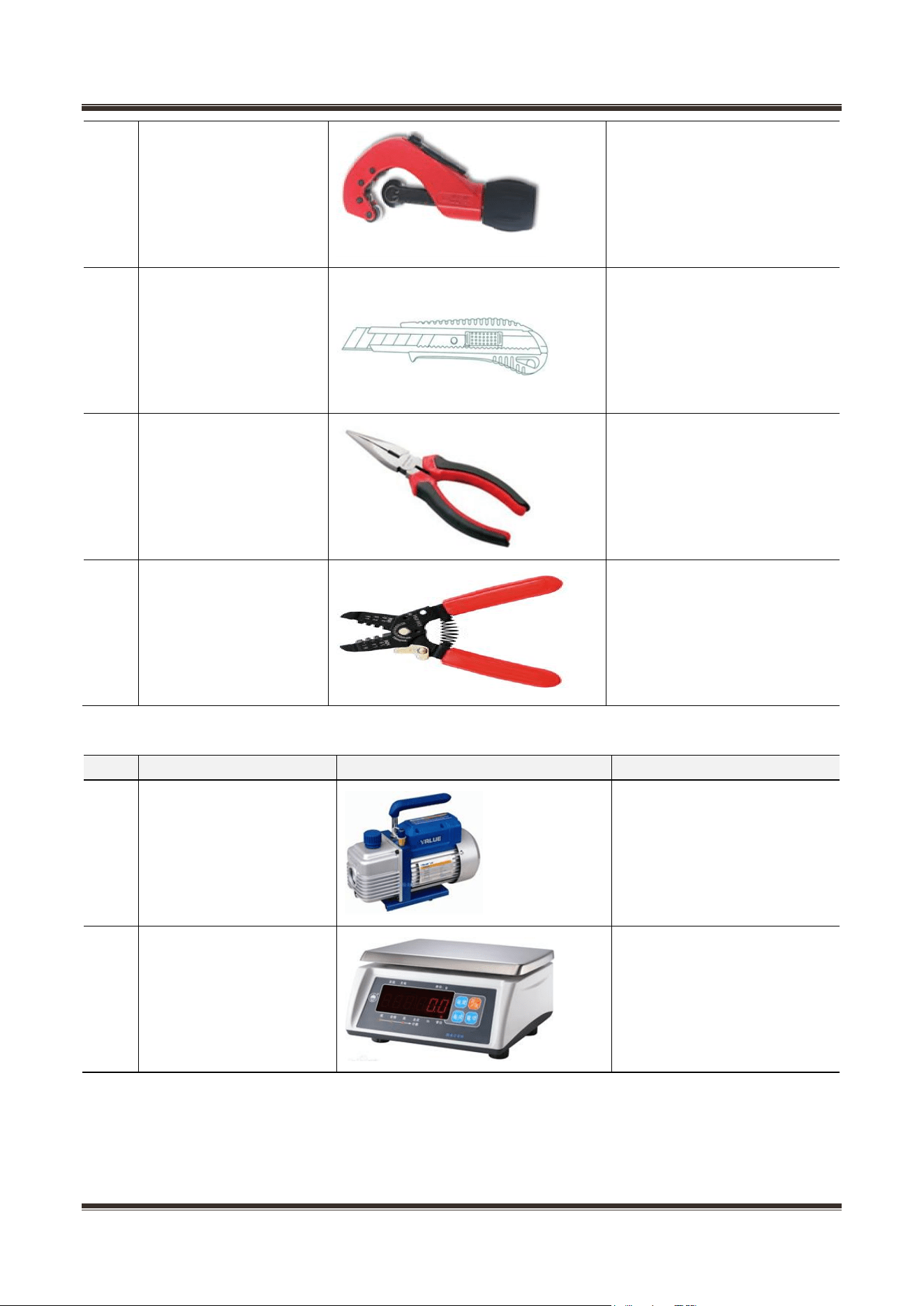
Tooling
No.
Name
Photo
Main Usage
1
Phillips screwdriver
screw assemble and
disassemble
2
slotted
screwdriver/scraper
screw and rivet assemble and
disassemble
3
Socket spanner 5/16″
hinge and compressor screw
assemble and disassemble
4
Sucker
display panel and air duct
cover disassemble
5
Allen wrench
(2.8~4mm)
handle assemble and
disassemble
6
Vise grip pliers
sealing process tube
Service Manual_
65
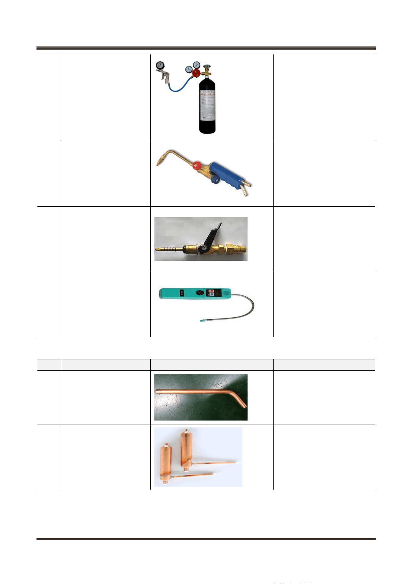
7
Pipe cutter
pipe cutting
8
Knife
assistive tool
9
Nipper pliers
assistive tool
10
Capillary tube scissors
Shear capillary
Equipment
No.
Name
Photo
Main Usage
1
Vacuum pump
vacuum pumping
2
Electronic scale
weighing refrigerant/gas
Service Manual_
66
3
High pressure nitrogen
with piezometer
pipe and cooling system
(condenser, evaporator, etc.)
impurities clean
4
Soldering gun
heating and welding
5
Quick coupling
connection process pipeline,
vacuum or charge refrigerant
will be used.
6
hand leak detector
welding point leakage detect,
if no, use soap-suds
Material
No.
Name
Photo
Main Usage
1
Process pipeline
Charge the refrigerant
2
Dry filter
Involving a system failure to
be replaced
Service Manual_
67
3
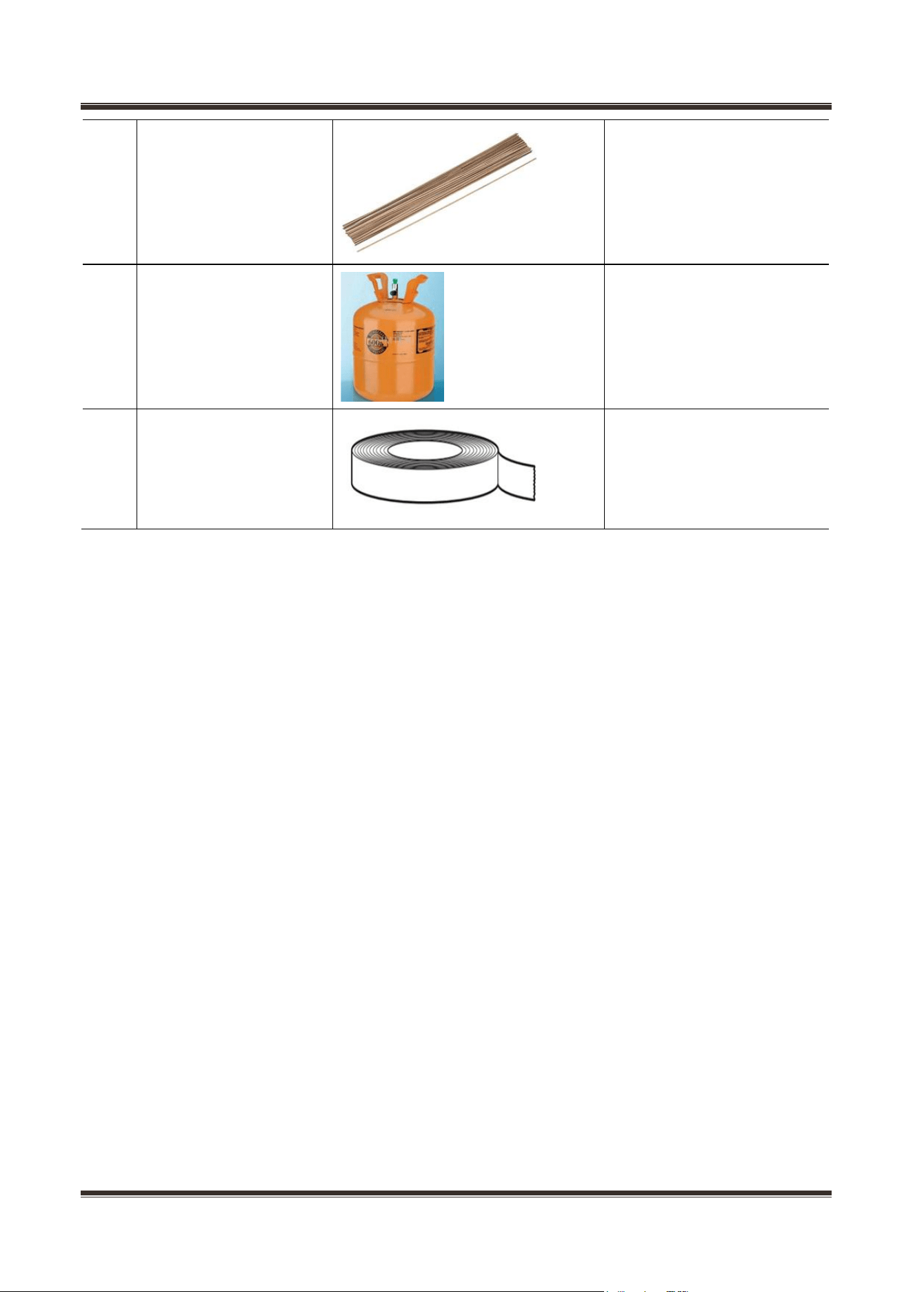
Copper welding rod
tube welding
4
Refrigerant/gas
Add refrigerant to the system
5
Sealing tape
door fixing for reversible door
option