McIntosh Laboratory, Inc. 2 Chambers Street Binghamton, New York 13903-2699 Phone: 607-723-3512 www.mcintoshlabs.com
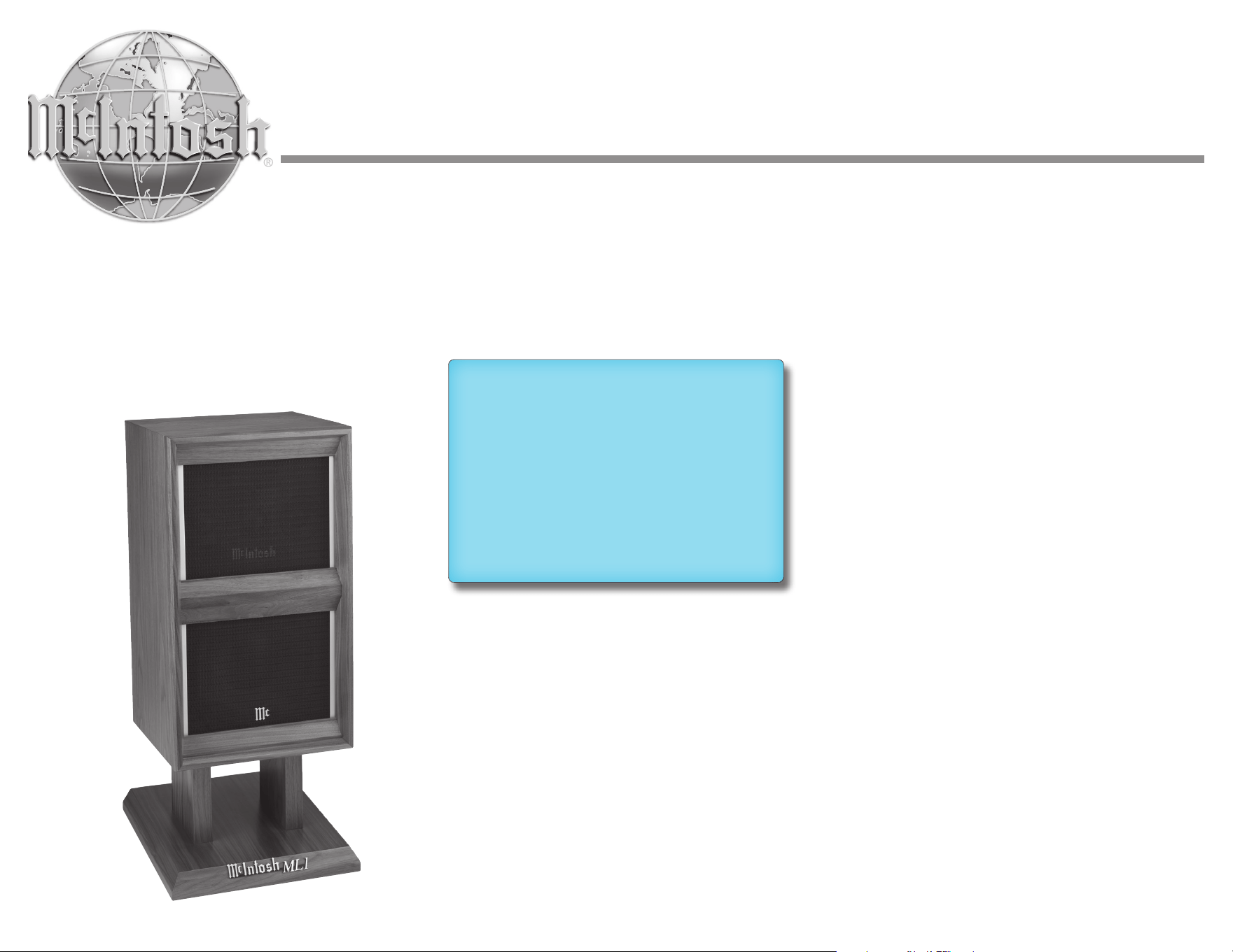
ML1
Loudspeaker System
Owner’s Manual
2
The lightning ash with arrowhead, within an equilateral
triangle, is intended to alert the user to the presence of
uninsulated “dangerous voltage” within the product’s en-
closure that may be of sucient magnitude to constitute
a risk of electric shock to persons.
The exclamation point within an equilateral triangle is
intended to alert the user to the presence of important
operating and maintenance (servicing) instructions in
the literature accompanying the appliance.
WARNING - TO REDUCE RISK OF FIRE
OR ELECTRICAL SHOCK,
DO NOT EXPOSE THIS EQUIPMENT
TO RAIN OR MOISTURE
NO USER-SERVICEABLE PARTS IN-
SIDE. REFER SERVICING
TO QUALIFIED PERSONNEL
To prevent the risk of electric shock,
do not remove cover or back.
No user-serviceable parts inside.
1. Read these instructions.
2. Keep these instructions.
3. Heed all warnings.
4. Follow all instructions.
5. Do not use this apparatus near water.
6. Clean only with a dry cloth.
7. Do not block any ventilation openings.
Install in accordance with the manufacturer’s
instructions.
8. Do not install near any heat sources such
as radiators, heat registers, stoves, or other
apparatus (including ampliers) that produce
heat.
9. Do not defeat the safety purpose of the polar-
ized or grounding-type plug. A polarized plug
has two blades with one wider than the other.
A grounding type plug has two blades and a
third grounding prong. The wide blade or the
third prong are provided for your safety. If
the provided plug does not t into your outlet,
consult an electrician for replacement of the
obsolete outlet.
10. Protect the power cord from being walked on
or pinched particularly at plugs, convenience
receptacles, and the point where they exit from
the apparatus.
11. Only use attachments/accessories specied by
the manufacturer.
12. Use only with the cart, stand,
tripod, bracket, or table speci-
ed by the manufacturer, or
sold with the apparatus. When
a cart is used, use caution when
moving the cart/apparatus combination to
avoid injury from tip-over.
13. Unplug this apparatus during lightning storms
or when unused for long periods of time.
14. Refer all servicing to qualied service person-
nel. Servicing is required when the apparatus
has been damaged in any way, such as
power-supply cord or plug is damaged, liquid
has been spilled or objects have fallen into the
apparatus, the apparatus has been exposed to
rain or moisture, does not operate normally, or
has been dropped.
15. Do not expose this equipment to dripping or
splashing and ensure that no objects lled
with liquids, such as vases, are placed on the
equipment.
16. To completely disconnect this equipment from
the AC mains, disconnect the AC / DC adapter
from the AC receptacle.
17. The mains plug of the power supply cord
shall remain readily operable. If the AC /
DC Adapter is provided with a mains power
supply cord attachment, the plug of this power
supply cord shall remain readily operable.
18. Do not expose batteries to excessive heat such
as sunshine, re or the like.
19. Connect mains power supply cord only to a
mains socket outlet with a protective earthing
connection.
WA R N I NG:
Use this product only with
the Power Adapter provided.
Failure to do so may result
in re and/or electrical shock.
IMPORTANT
SAFETY INSTRUCTIONS!
PLEASE READ THEM BEFORE
OPERATING THIS EQUIPMENT.

3
Copyright 2023 © by McIntosh Laboratory, Inc.
Thank You from all of us at McIntosh
You have invested in a precision instrument that will
provide you with many years of enjoyment. Please
take a few moments to familiarize yourself with
the features and instructions to get the maximum
performance from your equipment.
If you need further technical assistance, please
contact your dealer who may be more familiar with
your particular setup including other brands. You can
also contact McIntosh with additional questions or in
the unlikely event of needing service.
McIntosh Laboratory, Inc.
2 Chambers Street
Binghamton, New York 13903
Technical Assistance (607) 723-3512
Fax (607) 724-0549
Customer Service (607) 723-3515
Fax (607) 723-1917
Email support@mcintoshlabs.com
www.mcintoshlabs.com
Please Take A Moment
For future reference, you can write down your serial
number and purchase information here.
We can identify your purchase from this information
if the occasion should arise:
Serial Number: __________________________
Purchase Date: ___________________________
Dealer Name: ___________________________
Table of Contents
General Information .. .. .. .. .. .. .. .. .. .. .. 3
Performance Features.. .. .. .. .. .. .. .. .. .. .. 4
Introduction.. .. .. .. .. .. .. .. .. .. .. .. .. .. .. 5
ML1 Stand .. .. .. .. .. .. .. .. .. .. .. .. .. .. .. 6
ML1 Stand Dimensions . .. .. .. .. .. .. .. .. .. 6
ML1 Dimensions . .. .. .. .. .. .. .. .. .. .. .. .. 7
Input Terminals .. .. .. .. .. .. .. .. .. .. .. .. .. 8
Unpacking the Loudspeaker .. .. .. .. .. .. .. .. 8
Installation .. .. .. .. .. .. .. .. .. .. .. .. .. .. .. 9
Loudspeaker Placement.. .. .. .. .. .. .. .. .. .. 9
Home Theater Setup .. .. .. .. .. .. .. .. .. .. .. 9
Music System Setup .. .. .. .. .. .. .. .. .. .. .. 9
How to Connect Using One Amplifier .. .. .. ..10
Connection Diagram (one amplifier).. .. .. .. ..11
How to Connect Using Two Amplifiers.. .. .. ..12
Connection Diagram (two amplifiers) .. .. .. ..13
Specifications .. .. .. .. .. .. .. .. .. .. .. .. .. ..14
Packing Instructions .. .. .. .. .. .. .. .. .. .. ..14
ML1 Packing Parts List .. .. .. .. .. .. .. .. .. ..15
Stand Packing Parts List. .. .. .. .. .. .. .. .. ..15
General Information
Caution: The ML1 weight is 68.5 pounds (31.1 kg). It
requires two or more persons to safely handle it.
1. For additional connection information, refer
to the owner’s manual(s) for any component(s)
connected to the ML1.
2. The ML1 has an American Walnut veneer
which contains natural variations in wood grain
giving each speaker a unique appearance.
3. If there is an obvious lack of high, mid or low
frequencies after extended periods of overdrive,
the Protection Device(s) may have activated.
These devices will automatically reset when the
volume level is greatly reduced until the output
of the aected Loudspeaker Driver(s) returns to
normal.
4. When discarding the unit, comply with
local rules or regulations. Batteries
should never be thrown away or incinerated but
disposed of in accordance with the local regula
-
tions concerning battery disposal.
5. For additional information on the ML1 and
other McIntosh products please visit the
McIntosh website at www.mcintoshlabs.com.

4
Performance Features
• Woofers with Patented LD/HP
®
Technolog y
The McIntosh Low Frequency Loudspeaker
Elements feature the patented LD/HP Magnetic
Circuit Design. This design, when compared to
conventional Loudspeaker Drivers, reduces distor
-
tion signicantly. It also increases power handling
and eciency.
The rear vent through the magnetic assembly
oers improved heat dissipation. The die cast
basket has an open air area under the voice coil/
spider assembly to prevent displacement noise. The
polypropylene cone with a rubber surround has a
four layer copper voice coil and is rigid to perform
as a near perfect air piston.
All together these advances in woofer design
construction and materials produce the very
important rst several octaves of music, with
a high degree of accuracy and superb transient
response. This performance level rivals woofers
twice the size of the ML1 woofer.
• Neodymium-Iron-Boron Alloy Magnets
The 2 inch Midrange Driver and the 3/4 inch Dome
Super Tweeter all use this Alloy. The Neodymium-
Iron-Boron Alloy has the highest ux density per
unit of volume. This allows for a smaller physical
size driver and thus closer driver to driver place
-
ment for improved dispersion.
• Midrange Crossover Points
The ML1 uses two types of midrange units:
lower midrange/woofer and upper midrange.
The midrange band has been broken up into two
sections in order to aid the transition of output
from the woofer to the upper midrange frequen
-
cies, and to reduce the amplitude requirements of a
midrange driver at low frequencies while radiating
higher frequencies, reducing doppler distortion.
The upper 2” midrange unit was specially designed
to have a low resonance so its crossover point
can be lower than the typical 1 KHz of most
loudspeakers, and span the critical vocal region of
male and female singers.
Two 4 inch lower midranges are used in the ML1
to provide a symmetrical radiation pattern. This
improves the listening window and sonic imaging.
• Low Harmonic and Intermodulation
Distortion
The ML1 Loudspeaker System is capable of
reproducing the full dynamic range of a symphony
orchestra with very low audible distortion of any
kind.
• Sealed Enclosure
The ML1 uses acoustic suspension design
techniques. This type of loading was pioneered
decades ago, and uses a linear air spring of the
enclosure to keep distortion low, suspension under
control at all times, and provide an extended low
frequency output below resonance.
• High Power Handling
The Loudspeaker Elements and Crossover
Components of the ML1 are all chosen for use with
ampliers up to 600 watts, yet can be driven with a
75 watt amplier.
• Loudspeaker Protection
The ML1’s built-in speaker protection incorporates
four automatic resetting solid-state devices in the
crossover network. One protects the tweeters, one
each for the low and upper midrange drivers and
one for the woofers.
• Superior Imaging
Locating the Super Tweeter between the multiple
Midrange drivers generates a symmetrical polar
response for superior imaging. The Midrange and
Super Tweeter Drivers are precisely aligned and
closely spaced on the precision machined mount
-
ing plate of 5/8 inch thick aluminium.
• Versatile Operation
In additional to the regular connections, the ML1
provides separate connections for bi-amplication
and bi-wiring hookups.
• McIntosh Custom Binding Posts
McIntosh patented gold plated output terminals
deliver high current output. They accept large
diameter wire and spade lugs. Banana plugs may
also be used in the US and Canada.
• Loudspeaker Enclosure
The ML1 enclosure is constructed with multiple
front to back and side to side internal braces to
form a dampened rigid Loudspeaker enclosure.
The ML1 has a real wood veneer with a natural
stain and mild satin nish..
• Loudspeaker Grille
The solid grille is a throwback to the original ML1
design using solid walnut, acoustically transparent
cloth, and aluminum trim. The grille is held in
place by several neodymium magnets.
5
Introduction
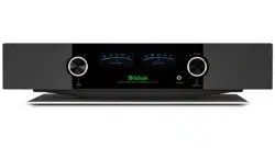
McIntosh Acoustic Engineers have achieved in
the design of the ML1 Loudspeaker System, a level
of high performance. The ML1 provides superior
spaciousness sound reproduction with unusual sound
stage depth in a full range system.
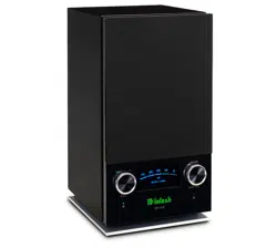
The enclosure is an important part of the ML1
Loudspeaker System. It has multiple front to back and
side to side internal braces to form a dampened rigid
Loudspeaker enclosure. The Loudspeaker’s small
footprint allows for a variety of different placements
in a room.
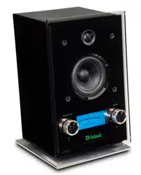
The ML1 utilizes a 3/4 inch Titanium
Dome Tweeter, a 2 inch soft dome upper
midrange, two 4 inch lower mid/woofers,
and a 12 inch high performance woofer.
Since the audio power is distributed
among all the drivers, each driver does not have to
work as hard, resulting in greater power handling
capability, dramatic reduction in distortion and
greater dynamic range.
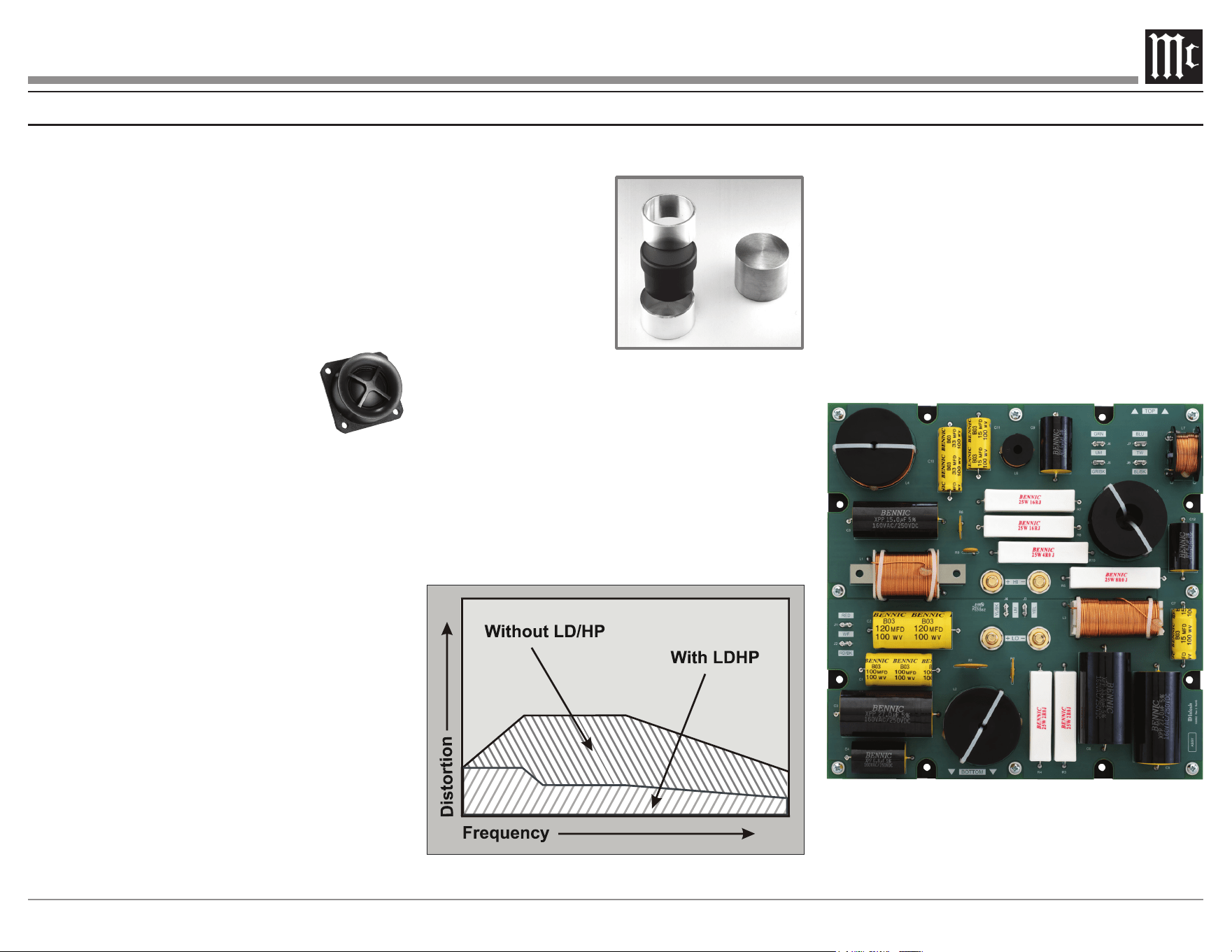
The Low Frequency Section of the System consists
of a newly designed 12 inch Woofer.
The new 12 inch
woofer incorporates Mc-
Intosh’s patented LD/HP
®
Magnetic Circuit Design.
Finite Element Analysis
and testing resulted in a
design concept which uti-
lizes aluminum sleeves in
the magnetic circuit.
The sleeves greatly reduce the negative influence
of the fluctuating voice coil field on the permanent
magnet field. This results in lower distortion due to
more linear magnetic flux in the voice coil gap.
Additional benefits are less volume compression
due to improved heat transfer through the sleeves and
a cooler operating voice coil. Both measurements, as
well as critical listening, reveal ten times less distor-
tion than previous designs. A good example of this
low distortion is incredible smoothness and clarity in
the reproduction of the human voice.
LD/HP
Conventional
The Crossover Network used in the ML1 Loud-
speaker System is designed to ensure an even fre-
quency response over the entire audible range. The
Second Order Designed Network utilizes capacitors
and inductors with high current capacity. The ML1
uses low loss (DCR) inductors in the crossover net-
work. The type of inductor used in each section of the
crossover network has been chosen for high linearity,
even at high power levels. This prevents distortion of
the music at any frequency. The capacitors used are
the low loss (ESR) types. The Network also utilizes
self resetting high current PTC Fuses to provide an
extra measure of protection.
6
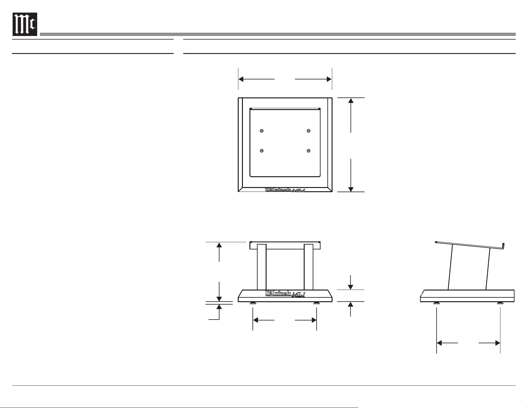
ML1 Stand Dimensions
The following dimensions can assist in determining the best location for your ML1.
16”
40.6 cm
2”
5.1 cm
13”
33 cm
13”
33 cm
10 1/4”
26 cm
3/8”
.9 cm
16”
40.6 cm
ML1 Stand
The dedicated stand for the ML1 has been designed
to elevate and position the ML1 loudspeaker for
optimum listening enjoyment and imaging. The stand
comes with feet for use on hard oors, and spikes for
use on carpet, etc.
7
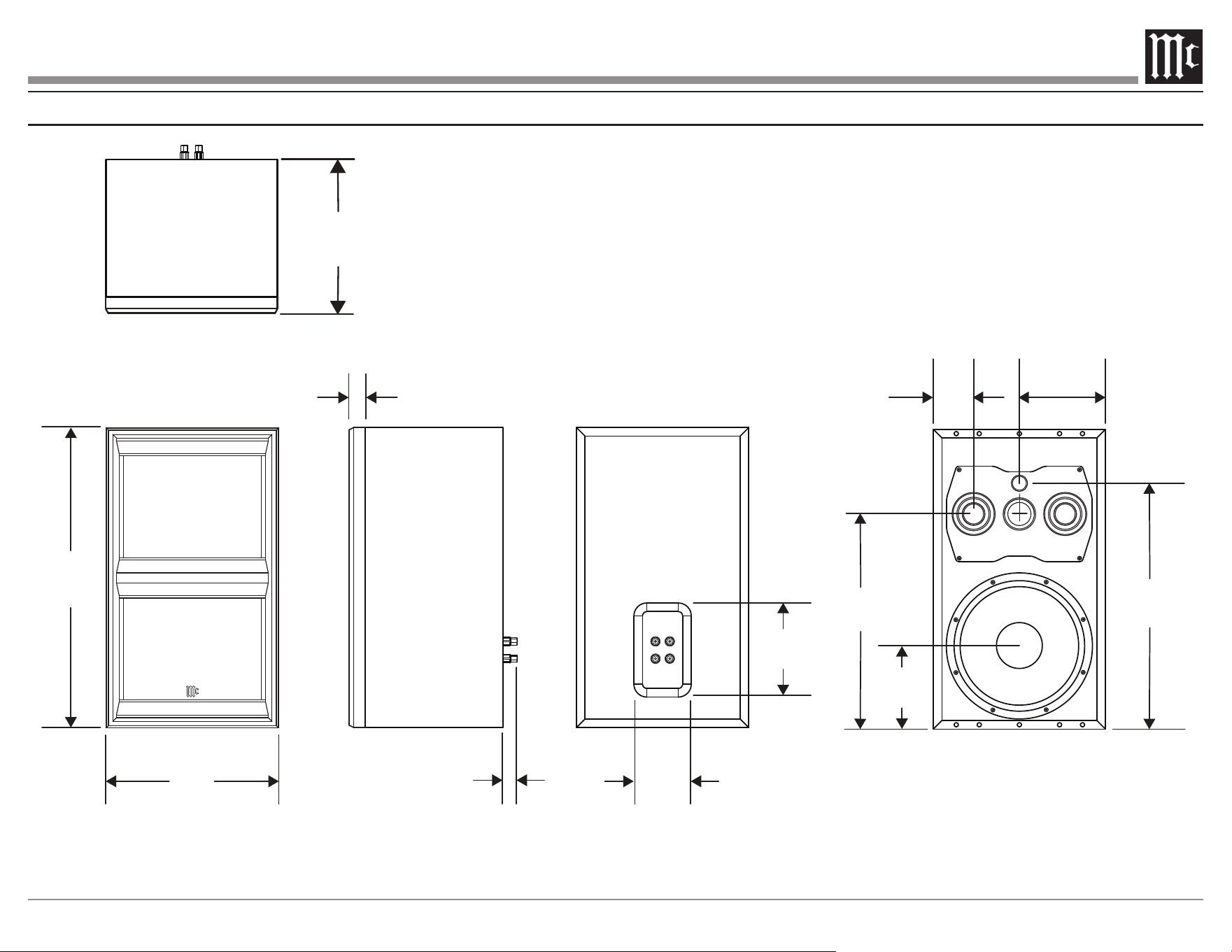
ML1 Dimensions
The following dimensions can assist in determining the best location for your ML1.
26 1/8”
66.4 cm
15”
38.1 cm
1 1/4”
3.2 cm
1 3/8”
3.5 cm
5”
12.7 cm
8 3/16”
20.8 cm
18 3/4”
47.6 cm
7 1/4”
18.4 cm
3 1/2”
8.9 cm
7 1/2”
19.1 cm
21 7/16”
54.5 cm
13 3/8”
34 cm
8
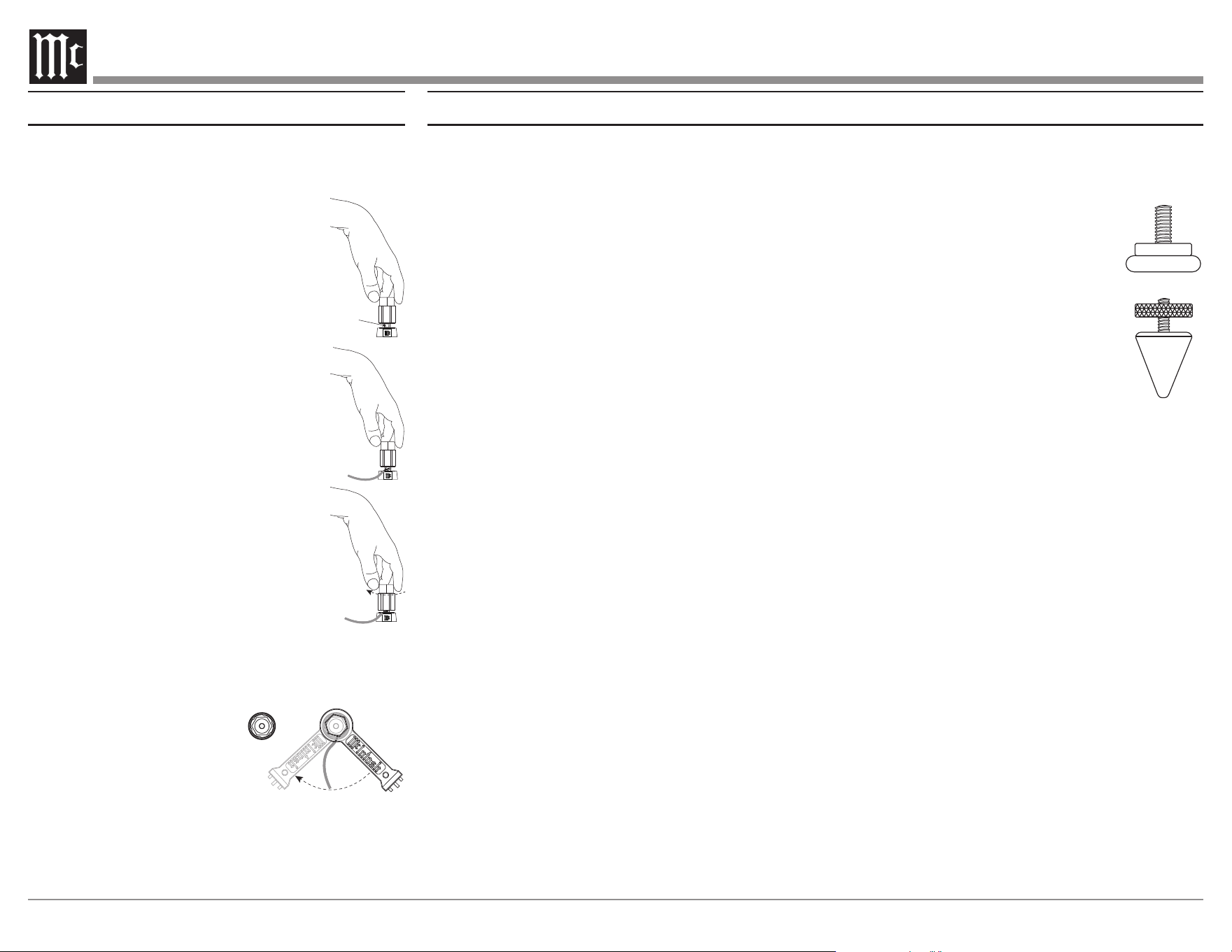
6. Repeat steps 1 and 2 on the ML1 Stand shipping
carton and remove the stand from the carton.
7. Place the stand, with the front facing up, on top
of the polybag.
8. Stand is pre-assembled with glides,
use supplied spikes in place of glides
by unscrewing glides from bottom of
stand.
9. Turn the stand upright and place it in
the desired location. The Glides or
Spikes can be independently adjusted
to compensate for uneven ooring or
to aim the loudspeakers upward or
downward.
Note: Retain the shipping carton, foam packing material and
polybag for possible future use.
10. Place the ML1 loudspeaker on top of each stand,
and center on the top metal panel.
11. Orient the Loudspeaker Grille so the front Logo
is at the bottom and oriented properly. Locate the
grille on the bottom front of the cabinet and the
internal magnets will draw tightly. Bring the top
towards the cabinet and the grille will attach.
Unpacking the Loudspeaker, Stand, and Attaching the Feet
Caution: It is very important to install the four feet on
the bottom of the stand. This will greatly prevent
possible injury to small children and family pets.
If the Loudspeaker is to be installed into custom
cabinetry the stand need not be used.
To protect the ne nish of the ML1 during the
installation process, it is advisable to prepare a
suitable area. A freshly vacuumed carpeted area
covered with a soft, clean fabric, such as a large bed
linen or blanket would be suitable.
It is recommended that the professionals at your
McIntosh Dealer, who are skilled in all aspects of
installation and operation, install the ML1 and any
associated audio equipment.
Note: Refer to illustration on page 15 for unpacking the
loudspeaker.
1. Orient the ML1 shipping carton with the lettering
on the outside of the carton oriented upward.
2. Carefully cut open the shipping carton sealing
tape and open the carton aps.
3. Place the shipping carton on a at surface with
the open aps on the ground. Lift the shipping
carton o the foam encapsulated ML1 speaker
carefully.
4. Release the Loudspeaker and the Grille from the
foam caps and set them aside.
5. Carefully remove the polybag from the ML1 and
Grille so as not to mar the nish.
Glides
Spikes
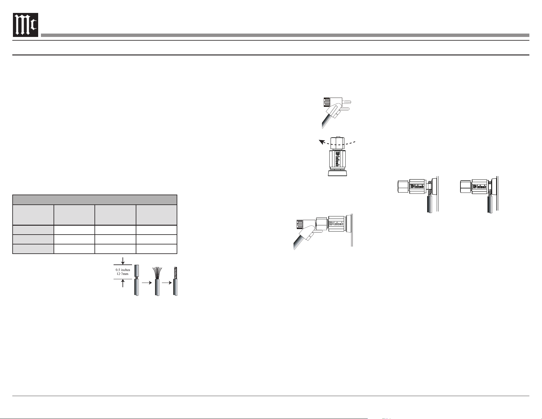
Input Terminals
When connecting the loudspeaker hookup cables to
the amplier output terminals please follow the steps
below:
1. Rotate the top of the output terminal
post counterclockwise until an
opening appears.
Opening
2. Insert the loudspeaker hookup cable
into the output terminal post opening
or the cable spade lug around the
center post of the output terminal.
3. Rotate the top of the output terminal
Post clockwise until it is nger tight.
4. Place the supplied McIntosh wrench
over the top of the output terminal and rotate
it one quarter of a turn (90°) to secure the
loudspeaker cable connection. Do not over
tighten. .
9
Installation
Loudspeaker Placement
Loudspeaker placement in a room can greatly affect
performance. The ML1 loudspeaker is designed for
both Music and Home Theater Systems. The optimal
method for selecting speaker locations includes the
use of a real time spectrum analyzer operated by an
experienced system installer. An uncompromising
installation would take into consideration the floor,
wall and ceiling coverings, the type and placement
of furniture and can even include the architectural
design of the room and its construction materials. In
those instances where placement in the room is fixed,
an environmental equalizer may be needed to restore
proper musical balance.
Placement near a wall, corner, floor, ceiling or any
intersecting surfaces will reinforce or diminish some
bass frequencies. The bass frequencies that are altered
by placement in a particular location is dependent on
the dimensions of the room. If professional measure-
ment equipment is not available, listen to the Loud-
speaker. Try various locations by listening to music
containing continuous bass and finding a location
where there is an over all musical balance in the sound
and the bass content does not dominate.
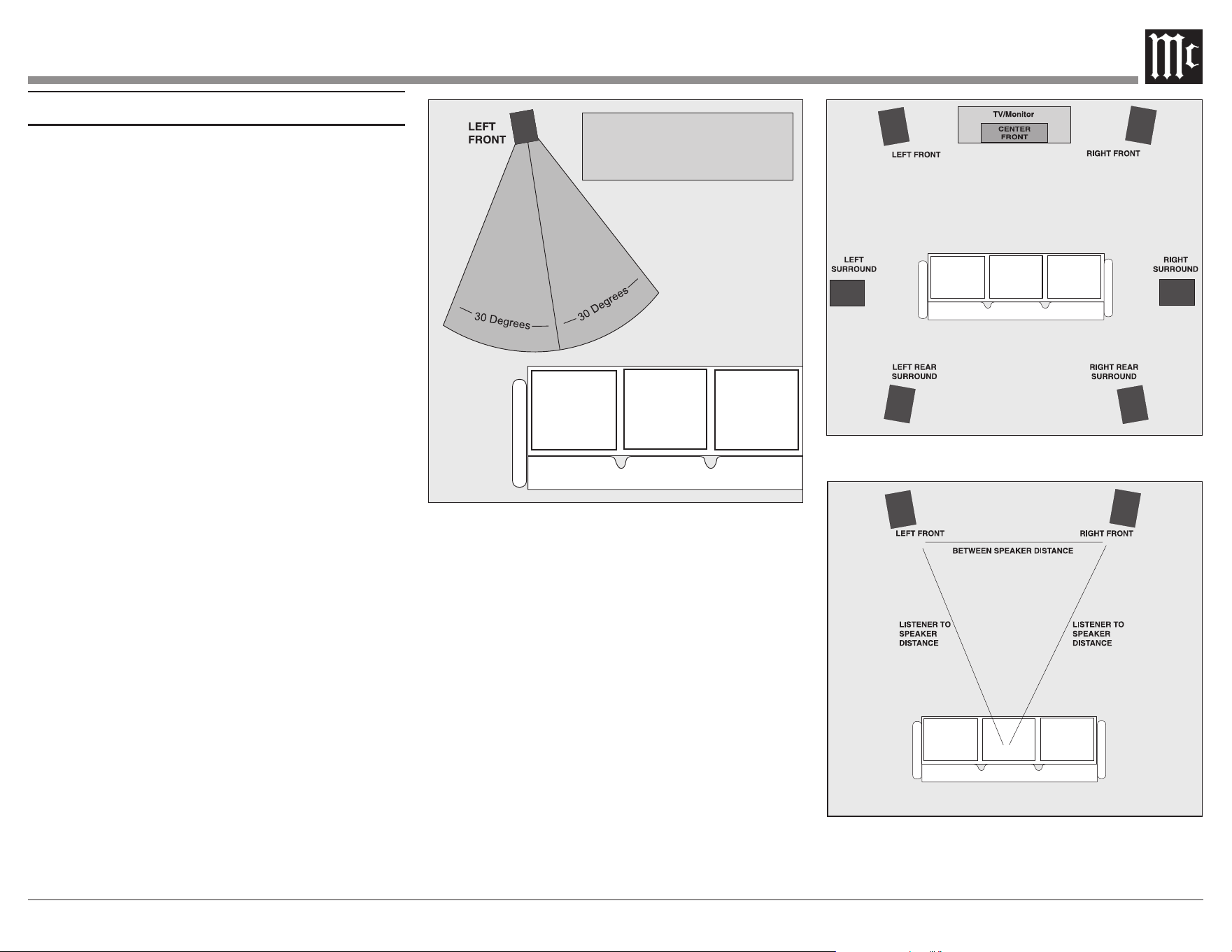
The ML1’s Smooth Frequency Response may be
altered by a large object(s) located in the sound waves
path or by locating the Loudspeaker too close to a side
wall. There should be an unobstructed area in front
of the Loudspeaker of at least 30 degrees either side
from the center axis for the best performance. Refer to
figure 9.
Figure 9
Figure 11
Figure 10
Locating Loudspeakers for use in Home Theater
In a Home Theater application, the placement of Left
and Right Front Loudspeakers can be limited by such
considerations as the size and location of the video
monitor. The locating suggestions in the “for use in a
Music System” section can still be helpful as a starting
place. Refer to figure 10.
Locating Loudspeakers for use in a Music System
When used in a music system, the distance between
the Loudspeakers and the listener to the Loudspeak-
ers should form an equilateral or an acute isosceles
triangle. If the speakers are too far apart relative to the
listener, some imaging can be lost. Refer to figure 11.
10
How to Connect Using One Amplier
Caution: The AC Power Cord should not be connected
to the Amplifier until after the Loudspeaker
Connections have been made. Failure to observe
this could result in Electric Shock.
When connecting a ML1 Loudspeaker to an amplifier
it is very important to use cables of adequate size, so
there is little to no power loss in the cables. The size is
specified in Gauge Numbers or AWG (American Wire
Gauge). The smaller the Gauge number, the larger the
wire size:
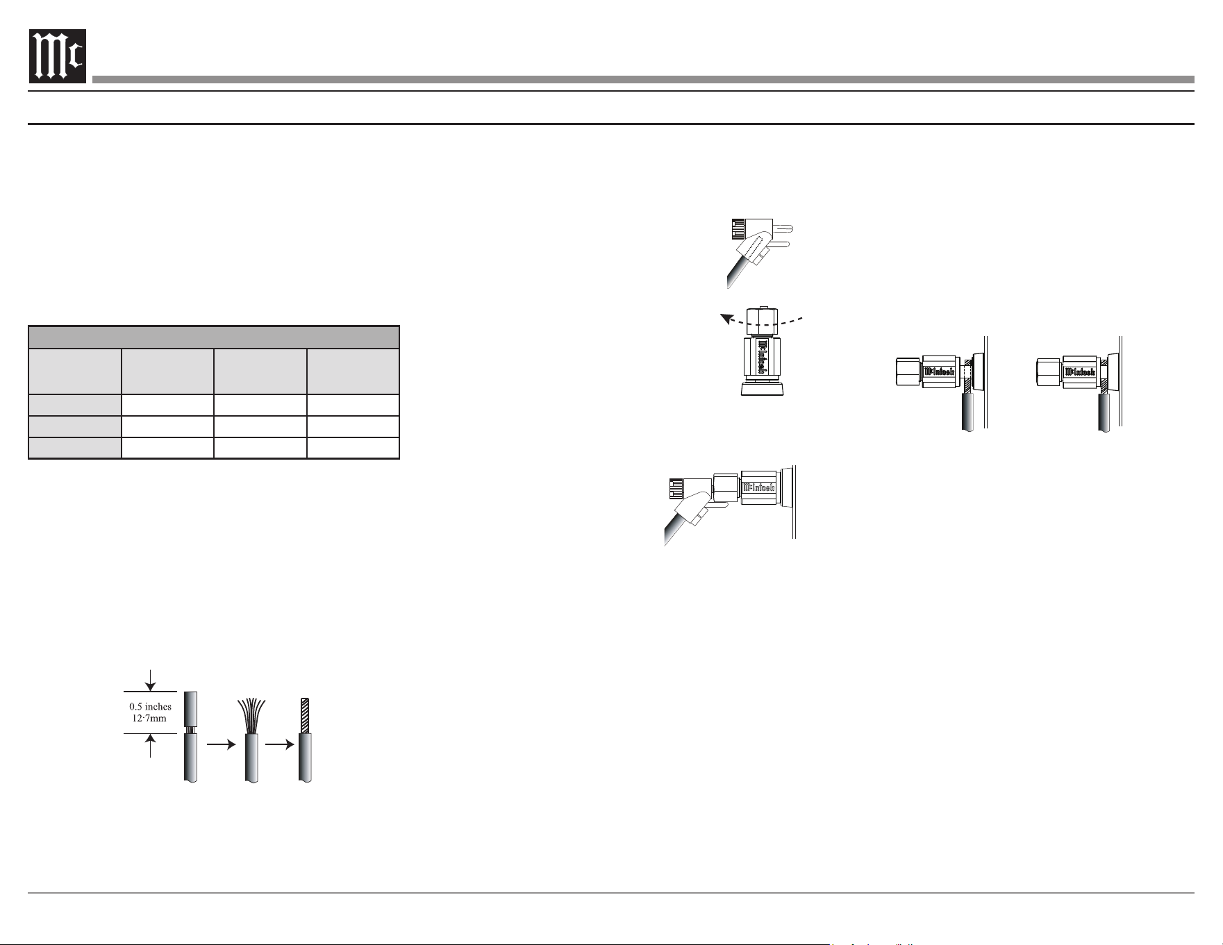
Loudspeaker Cable Distance vs Wire Gauge Guide
Loudspeaker
Impedance
25 feet
(7.62 meters)
or less
50 feet
(15.24 meters)
or less
100 feet
(30.48 meters)
or less
2 Ohms
12AWG 10AWG 8AWG
4 Ohms
14AWG 12AWG 10AWG
8 Ohms
16AWG 14AWG 12AWG
Prepare Loudspeaker cables using the instructions
below:
1. Carefully remove sucient insulation from
the cable ends, refer to gure 1. If the cable is
stranded, carefully twist the strands together as
tightly as possible.
Notes: 1. If desired, the twisted ends can be tinned with solder to
keep the strands together.
2. The prepared bare wire cable ends may be inserted into
spade lug connectors.
Select from the following options to connect the ML1:
Banana Plugs:
Caution: Banana Plugs are for use in the United States
and Canada only:
2. Attach the previously prepared bare
wire cable ends into the banana plugs
and secure the connections. Refer to
gure 2.
3. Rotate the top of the Output Terminal
Post clockwise until it is nger tight.
Refer to gure 3. Then using the
McIntosh Wrench, rotate the top of
the Output Terminal one quarter of a
turn (90°). Do not over tighten.
4. Referring to gure 4, connect the Loudspeaker
hookup cables with banana plugs into the hole at
the end of the terminal to the
ML1 Negative (-) LOW Input
Terminal and Positive (+)
LOW Input Terminal.
Note: It is important to maintain the correct polarity at both ends
of the Loudspeaker cables.
5. Connect the other end of the Loudspeaker cables
coming from the ML1 Negative (-) and Positive
(+) LOW Input Terminals to the Left Channel
Negative (-) and Positive (+) 8 Ω Output Terminal
of the Amplier.
6. Connect the second ML1 Loudspeaker in a
similar manner to the Amplier.
Figure 1
Figure 2
Figure 4
Figure 3
Spade Lug or Wire Connections:
Figure 2
Figure 4
Figure 5
Figure 6
2. Connect the Loudspeaker hookup cables to the
ML1 Negative (-) Input Terminal and Positive (+)
Input Terminal. Insert the spade lug connector or
prepared section of the cable end into the Input
Terminal side access hole, and tighten the Input
Terminal cap until the cable is rmly clamped
into the terminals so the lugs or wire cannot slip
out. Refer to gures 5 and 6.
Note: It is important to maintain the correct polarity at both ends
of the Loudspeaker cables.
3. Connect the other end of Loudspeaker cables
coming from the ML1 Negative (-) LOW Input
Terminal to the Left Channel COM (-) 8 Ω
Output Terminal of the Amplier.
4. In a similar manner, connect the Loudspeaker
cables coming from the second ML1 Positive (+)
LOW Input Terminal to the Left Channel 8 Ω (+)
Output Terminal of the Amplier.
5. Connect the second ML1 Loudspeaker in a
similar manner to the Amplier’s Right Channel
Terminals.
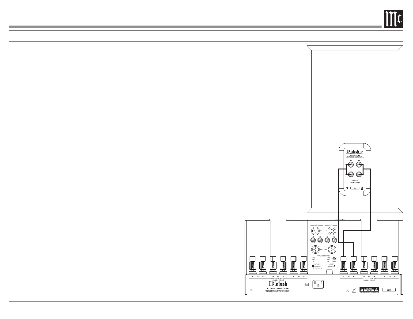
11
Connection Diagram (one amplier)
DISABLED
12
How to Connect Using Two Ampliers
Caution: The AC Power Cord should not be connected
to the Amplifier until after the Loudspeaker
Connections have been made. Failure to observe
this could result in Electric Shock.
Note: When the ML1 Loudspeaker System is driven by two
amplifiers, the output levels of different model amplifiers
connected to the Loudspeaker System must be adjusted to
achieve a proper balance between the low and midrange/
high frequencies reproduced. This adjustment is best
achieved through the use of audio test equipment operated
by a qualified installer.
When connecting a ML1 Loudspeaker to two amplifi-
ers it is very important to use cables of adequate size,
so there is little to no power loss in the cables. The
size is specified in Gauge Numbers or AWG (Ameri-
can Wire Gauge). The smaller the Gauge number, the
larger the wire size:
Loudspeaker Cable Distance vs Wire Gauge Guide
Loudspeaker
Impedance
25 feet
(7.62 meters)
or less
50 feet
(15.24 meters)
or less
100 feet
(30.48 meters)
or less
2 Ohms
12AWG 10AWG 8AWG
4 Ohms
14AWG 12AWG 10AWG
8 Ohms
16AWG 14AWG 12AWG
Prepare Loudspeaker cables
using the instructions below:
1. Carefully remove sucient
insulation from the cable
ends, refer to gure 1. If
the cable is stranded, carefully twist the strands
together as tightly as possible.
Notes: 1. If desired, the twisted ends can be tinned with solder to
keep the strands together.
2. The prepared bare wire cable ends may be inserted into
spade lug connectors.
2. Remove the ML1 metal jumpers between the
Negative (-) LOW and HIGH/MID Terminals and
between the Positive (+) LOW and HIGH/MID
terminals. Retain them for possible future use.
Select from the following options to connect the ML1:
Banana Plugs:
Caution: Banana Plugs are for use in the United States
and Canada only:
3. Attach the prepared bare wire cable
ends into the banana plugs and secure
the connections. Refer to gure 2.
4. Rotate the top of the Output Terminal
Post clockwise until it is nger tight.
Refer to gure 3. Then using the
McIntosh Wrench, rotate the top of
the Output Terminal one quarter of a
turn (90°). Do not over tighten.
5. Referring to gure 4, connect
the Loudspeaker hookup cables with banana
plugs into the hole at the end of the ML1 LOW
Negative (-) and Positive (+) Input Terminals.
Then connect cables to the
ML1 HIGH/MID Negative
(-) and Positive (+) Input
Terminals.
Note: It is important to maintain the correct polarity at both ends
of the Loudspeaker cables.
6. Connect cables from the ML1 LOW Terminals
to the Left Channel Negative (-) and Positive
(+) 8 Ω Output Terminals of Power Amplier
Two. Then connect cables from the ML1 HIGH/
MID Terminals to the Left Channel Negative (-)
and Positive (+) 8 Ω Output Terminals of Power
Amplier One.
7. Connect the other Loudspeaker in a similar
manner to the Right Channel Output Terminals
of the Power Ampliers.
Figure 1
Figure 2
Figure 4
Figure 3
Spade Lug or Wire Connections:
3. Referring to the illustration connect the
Loudspeaker hookup cables to the ML1 Negative
(-) Input Terminal and Positive (+) Input
Terminal. Insert the spade lug connector or
prepared section of the cable end into the Input
Terminal side access hole, and tighten the Input
Terminal cap until the cable is rmly clamped
into the terminals so the lugs or wire cannot slip
out. Refer to gures 5 and 6. Then connect cables
to the ML1 HIGH/MID Negative (-) and Positive
(+) Input Terminals.
Note: It is important to maintain the correct polarity at both ends
of the Loudspeaker cables.
4. Connect cables from the ML1 LOW Terminals
to the Left Channel Negative (-) and Positive
(+) 8 Ω Output Terminals of Power Amplier
Two. Then connect cables from the ML1 HIGH/
MID Terminals to the Left Channel Negative (-)
and Positive (+) 8 Ω Output Terminals of Power
Amplier One.
5. Connect the other Loudspeaker in a similar
manner to the Right Channel Output Terminals
of the Power Ampliers.
Figure 2
Figure 4
Figure 5
Figure 6
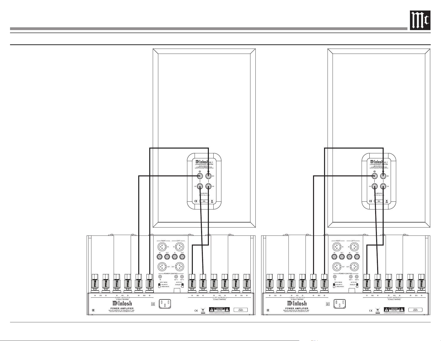
13
Connection Diagram (two ampliers)
DISABLEDDISABLED
Note: Jumpers must be removed
for this arrangement.

14
Specications
System Driver Complement
One 12 inch Woofer (incorporating LD/HP)
One 2 inch soft dome Upper Midrange
Two 4 inch lower midranges
One 3/4 inch Titanium Dome Tweeter
Impedance
8 ohms Nominal
Frequency Response
27Hz - 45,000Hz
Sensitivity
85 dB (2.83V/1m equivalent)
Crossover Frequencies
180Hz
500Hz
4500Hz
Recommended Power Range
75 Watts to 600 Watts
Maximum Power Handling
600 Watts
General Specications
Enclosure Finish
American Walnut veneers and solids with satin nish
Grille Finish
Solid American Walnut with satin nish, black knit
cloth with aluminum trim
ML1 Dimensions
Width is 15 inches (38.1cm)
Height is 26 1/8 inches (66.4cm)
Depth is 13 3/8 inches (34cm)
Stand Dimensions
Width is 16 inches (40.6cm)
Height is 10 1/4 inches (26cm)
Depth is 16 inches (40.6cm)
ML1 Weight
66 pounds (30 kg) net
75.3 pounds (34.2 kg) in shipping carton
Stand Weight
19 pounds (8.6 kg) net
25.3 pounds (11.5 kg) in shipping carton
ML1 Shipping Carton Dimensions
Width is 20 1/2 inches (52.1cm)
Depth is 20 1/2 inches (52.1cm)
Height is 30 1/2 inches (77.5cm)
Stand Shipping Carton Dimensions
Width is 20 1/2 inches (52.1cm)
Depth is 20 1/2 inches (52.1cm)
Height is 15 1/2 inches (38.6cm)
Packing Instructions
In the event it is necessary to repack the equipment
for shipment, the equipment must be packed exactly
as shown below.
Use the original shipping carton and interior parts
only if they are all in good serviceable condition.
If a shipping carton or any of the interior part(s)
are needed, please call or write Customer Service
Department of McIntosh Laboratory. Refer to page
3. Please see the packing part lists on the following
page for the correct part numbers.
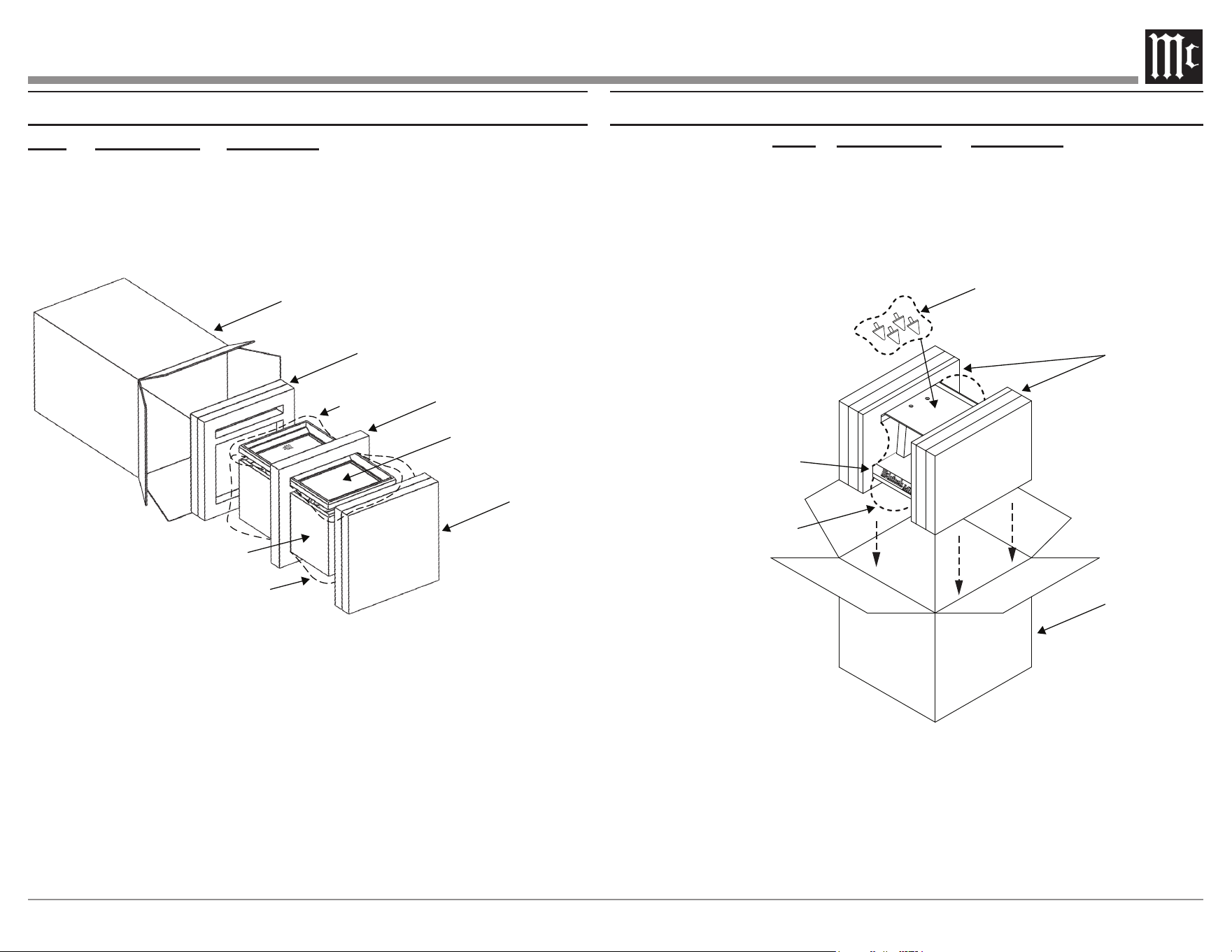
15
ML1 Packing Parts List
Qty Part Number Description
1 034701 Shipping Carton only
2 034702 Foam Tray Top/Bottom
1 034703 Foam Support Center
1 034718 Poly Bag (Speaker)
1 034719 Poly Bag (Grille)
Shipping Carton
Foam Tray / Bottom
Loudspeaker
Grille
Foam Support / Center
Foam Tray / Top
Loudspeaker
Poly Bag
(Speaker)
Poly Bag
(Grille)
Shipping Carton
Poly Bag
Foam End Caps
Speaker Stand
Cabinet Spikes
Qty Part Number Description
1 034714 Shipping Carton Speaker Stand
2 034712 Foam End Cap Stand
1 034718 Poly Bag (Speaker)
4 414174 Cabinet Spikes
1 033545 Bag Zip Loc 4x4
ML1 Stand Packing Parts List

The continuous improvement of its products is the
policy of McIntosh Laboratory Incorporated who
reserve the right to improve design without notice.
Printed in the U.S.A.
McIntosh Laboratory, Inc.
2 Chambers Street
Binghamton, NY 13903
www.mcintoshlabs.com
McIntosh Part No. 24119801