
Thank you very much for purchasing this Air Conditioner. Please
read this carefully before installing use and installation instructions
and using this appliance. And keep this manual for future reference.
Factory model Market model
AMD-09UX4RAL4 AMD-25UX4RAL4
ADT-12UX4RBL4 AMD-35UX4RBL4
ADT-18UX4RCL4 AMD-50UX4RCL4
AMD-24UX4RCL4 AMD-71UX4RCL4
Contents
Caution Statements.........................................................1
Safety Precautions ..........................................................3
Composition of the Air Conditioner..................................8
Operation Manual
Special Remarks .............................................................8
Troubleshooting...............................................................9
Filter Cleaning ...............................................................10
Installation and Maintenance
1. Safety Notice...................................................................11
2. Tools and Instruments for Installation .............................12
3. Installation of the Indoor Unit .........................................12
3.1 Initial Check............................................................12
3.2 Installation ..............................................................13
4. Refrigerant Pipe..............................................................14
4.1 Pipe Material ...........................................................14
4.2 ............................................14 Connection of the Pipe
5. Drain Piping ....................................................................15
6. Electrical Wiring ..............................................................16
6.1 General Check ........................................................16
6.2 Change of Static Pressure ......................................17
6.3 Electrical Installation ...............................................18
7. Test Run..........................................................................18
: The symbol refers to a hazard which can result in severe personal injury or death.
: The symbol refers to a hazard or an unsafe practice which may result in severe personal injury
or death.
: The symbol refers to a hazard or an unsafe practice which may result in personal injury,
product or property damage.
: It refers to the remarks and instruction to the operation, maintenance, and service.
DANGER
WARNING
CAUTION
NOTE
Alert Symbols:
This air conditioner should be installed properly by qualified personnel in accordance with the installation
instructions provided with the unit.
Before installation, check if the voltage of the power supply is the same as the voltage at installation site
shown on the nameplate.
You must not carry on any transformation to this product, otherwise, it may cause
water leakage, breakdown, short-circuit, electric shock, fire, and so on.
Piping, welding and other such works should be carried out far away from the
flammable explosive material vessels, including the air conditioner refrigerant, to
guarantee the security of the site.
To protect the air conditioner from heavy corrosion, avoid installing the outdoor unit
where sea water can splash directly onto it or in sulphurous air near a spa. Do not
install the air conditioner where excessively high heat-generating objects are placed.
DANGER
WARNING
If the supply cord is damaged, it must be replaced by the factory or its service
department in case of danger.
The place where this product is installed must have the reliable electrical grounding
facility and protection. Please do not connect the grounding of this product to various
kinds of air-feeding ducts, drain piping, lightning protection facility as well as other
piping lines to avoid receiving an electric shock and damages caused by other factors.
Wiring must be done by a qualified electrician. All the wiring must comply with the
local electrical codes.
Consider the capacity of the electric current of your electrical meter and socket
before installation.
CAUTION Statements
1
WARNING
The power wire where this product is installed is supposed to have the independent
leakage protective device and the electric current over-load protection device which
are provided for this product.
2
CAUTION Statements
Read this manual carefully before using this air conditioner. If you still have any
difficulties or problems, consult your dealer for help.
The air conditioner is designed to provide you with comfortable room conditions. Use
this unit only for its intended purpose as described in this instruction manual.
This appliance is not intended for use by persons (including children) with reduced
physical, sensory or mental capabilities, or lack of experience and knowledge, unless
they have been given supervision or instruction concerning use of the appliance by
a person responsible for their safety.
Means for disconnection, which can provide full disconnection in all poles, must be
incorporated in the fixed wiring in accordance with the wiring rules.
Never use gasoline or other inflammable gas near the air conditioner, which is very
dangerous.
When the air conditioner operation is abnormal, such as burnt smell, deformation, fire,
smoke, and so on, it is forbidden to continue using the air conditioner, the main power
switch of the air conditioner must be cut off immediately and the agent must be
contacted.
Do not turn the air conditioner on or off from the main power switch. Use the
ON/OFF operation button.
Do not stick anything into the air inlet and air outlet of both the indoor and outdoor
units. This is dangerous because the fan is rotating at a high speed.
Do not cool or heat the room too much if babies or invalids are present.
Details of type and rating of circuit breakers/ELB is detailed in outdoor instruction
manual.
The method of connection of the appliance to the electrical supply and interconnection
of separate components is detailed in the part below.
The wiring diagram with a clear indication of the connections and wiring to external
control devices and supply cord is detailed in part below. The cord of the H07RN-F
type or the electrically equivalent type must be used for power connection and
interconnection between outdoor unit and indoor unit. The size of the cord is detailed
in part below.
The information of dimensions of the space necessary for correct installation of the
appliance including the minimum permissible distances to adjacent structures is
detailed in part below.
The range of external static pressures for ducted appliances is detailed in part below.
WARNING
CAUTION
● Storage condition: Temperature -25~60℃
Humidity 30%~80%
NOTE:
3
Precautions for Using R32 Refrigerant
The basic installation work procedures are the same as the conventional refrigerant (R22 or R410A).
However, pay attention to the following points:
WARNING
1. Transport of Equipment Containing Flammable Refrigerants.
Attention is drawn to the fact that additional transportation regulations may exist with respect to equipment containing
flammable gas. The maximum number of pieces of equipment or the configuration of the equipment, permitted to be
transported together will be determined by the applicable transport regulations.
2. Marking of Equipment Using Signs
Signs for similar appliances (containing flammable refrigerants) used in a work area generally are addressed by local
regulations and give the minimum requirements for the provision of safety and/or health signs for a work location. All
required signs are to be maintained and employers should ensure that employees receive suitable and sufficient instruction
and training on the meaning of appropriate safety signs and the actions that need to be taken in connection with these signs.
The effectiveness of signs should not be diminished by too many signs being placed together. Any pictograms used should be
as simple as possible and contain only essential details.
3. Disposal of Equipment Using Flammable Refrigerants
Compliance with national regulations
4. Storage of Equipment/Appliances
The storage of equipment should be in accordance with the manufacturer's instructions.
5. Storage of Packed (unsold) Equipment
• Storage package protection should be constructed such that mechanical damage to the equipment inside the package will not
cause a leak of the refrigerant charge.
• The maximum number of pieces of equipment permitted to be stored together will be determined by local regulations.
6. Information on Servicing
6-1 Checks to the Area
Prior to beginning work on systems containing flammable refrigerants, safety checks are necessary to ensure that the risk of
ignition is minimized. For repair to the refrigerating system, the following precautions should be complied with prior to
conducting work on the system.
6-2 Work Procedure
Work shall be undertaken under a controlled procedure so as to minimise the risk of flammable gas or vapour being present
while the work is being performed.
6-3 General Work Area
• All maintenance staff and others working in the local area shall be instructed on the nature of work being carried out. Work in
confined spaces shall be avoided.
• The area around the workspace shall be sectioned off. Ensure that the conditions within the area have been made safe by
control of flammable material.
6-4 Checking for Presence of Refrigerant
• The area shall be checked with an appropriate refrigerant detector prior to and during work, to ensure the technician is aware
of potentially flammable atmospheres.
• Ensure that the leak detection equipment being used is suitable for use with flammable refrigerants, i.e. non-sparking,
adequately sealed or intrinsically safe.
6-5 Presence of Fire Extinguisher
• If any hot work is to be conducted on the refrigeration equipment or any associated parts, appropriate fire extinguishing
equipment shall be available to hand.
• Have a dry powder or CO fire extinguisher adjacent to the charging area.
2
6-6 No Ignition Sources
• No person carrying out work in relation to a refrigeration system which involves exposing any pipe work that contains or has
contained flammable refrigerant shall use any sources of ignition in such a manner that it may lead to the risk of fire or
explosion.
• All possible ignition sources, including cigarette smoking, should be kept sufficiently far away from the site of installation,
repairing, removing and disposal, during which flammable refrigerant can possibly be released to the surrounding space.
• Prior to work taking place, the area around the equipment is to be surveyed to make sure that there are no flammable
hazards or ignition risks. “No Smoking” signs shall be displayed.
6-7 Ventilated Area
• Ensure that the area is in the open or that it is adequately ventilated before breaking into the system or conducting any hot
work.
• A degree of ventilation shall continue during the period that the work is carried out.
• The ventilation should safely disperse any released refrigerant and preferably expel it externally into the atmosphere.
6-8 Checks to the Refrigeration Equipment
• Where electrical components are being changed, they shall be fit for the purpose and to the correct specification.
• At all times the manufacturer's maintenance and service guidelines shall be followed. If in doubt consult the manufacturer's
technical department for assistance.
Safety Precautions
4
•The following checks shall be applied to installations using flammable refrigerants:
– The charge size is in accordance with the room size within which the refrigerant containing parts are installed;
– The ventilation machinery and outlets are operating adequately and are not obstructed;
– If an indirect refrigerating circuit is being used, the secondary circuit shall be checked for the presence of refrigerant;
–Marking to the equipment continues to be visible and legible. Markings and signs that are illegible shall be corrected;
–Refrigeration pipe or components are installed in a position where they are unlikely to be exposed to any substance which
may corrode refrigerant containing components, unless the components are constructed of materials which are inherently
resistant to being corroded or are suitably protected against being so corroded.
6-9 Checks to Electrical Devices
• Repair and maintenance to electrical components shall include initial safety checks and component inspection procedures.
• If a fault exists that could compromise safety, then no electrical supply shall be connected to the circuit until it is satisfactorily
dealt with.
• If the fault cannot be corrected immediately but it is necessary to continue operation, an adequate temporary solution shall
be used.
• This shall be reported to the owner of the equipment so all parties are advised.
• Initial safety checks shall include:
• That capacitors are discharged: this shall be done in a safe manner to avoid possibility of sparking;
• That there no live electrical components and wiring are exposed while charging, recovering or purging the system;
• That there is continuity of earth bonding.
7. Repairs to Sealed Components
• During repairs to sealed components, all electrical supplies shall be disconnected from the equipment being worked upon
prior to any removal of sealed covers, etc.
• If it is absolutely necessary to have an electrical supply to equipment during servicing, then a permanently operating form of
leak detection shall be located at the most critical point to warn of a potentially hazardous situation.
• Particular attention shall be paid to the following to ensure that by working on electrical components, the casing is not altered
in such a way that the level of protection is affected.
• This shall include damage to cables, excessive number of connections, terminals not made to original specification, damage
to seals, incorrect fitting of glands, etc.
• Ensure that apparatus is mounted securely.
• Ensure that seals or sealing materials have not degraded such that they no longer serve the purpose of preventing the
ingress of flammable atmospheres.
• Replacement parts shall be in accordance with the manufacturer's specifications.
NOTE: The use of silicon sealants may inhibit the effectiveness of some types of leak detection equipment. Intrinsically safe
components do not have to be isolated prior to working on them.
8. Repair to Intrinsically Safe Components
• Do not apply any permanent inductive or capacitance loads to the circuit without ensuring that this will not exceed the
permissible voltage and current permitted for the equipment in use.
• Intrinsically safe components are the only types that can be worked on while live in the presence of a flammable atmosphere.
The test apparatus shall be at the correct rating.
• Replace components only with parts specified by the manufacturer.
• Other parts may result in the ignition of refrigerant in the atmosphere from a leak.
9. Cabling
• Check that cabling will not be subject to wear, corrosion, excessive pressure, vibration, sharp edges or any other adverse
environmental effects.
• The check shall also take into account the effects of aging or continual vibration from sources such as compressors or fans.
WARNING
Safety Precautions
5
WARNING
10. Detection of Flammable Refrigerants
• Under no circumstances shall potential sources of ignition be used in the searching for or detection of
refrigerant leaks.
• A halide torch (or any other detector using a naked flame) shall not be used.
11. Leak Detection Methods
The following leak detection methods are deemed acceptable for systems containing flammable refrigerants:
• Electronic leak detectors shall be used to detect flammable refrigerants, but the sensitivity may not be
adequate, or may need re-calibration. (Detection equipment shall be calibrated in a refrigerant-free area.)
• Ensure that the detector is not a potential source of ignition and is suitable for the refrigerant used.
• Leak detection equipment shall be set at a percentage of the LFL of the refrigerant and shall be calibrated to
the refrigerant employed and the appropriate percentage of gas (25 % maximum) is confirmed.
• Leak detection fluids are suitable for use with most refrigerants but the use of detergents containing
chlorine shall be avoided as the chlorine may react with the refrigerant and corrode the copper pipe-work.
• If a leak is suspected, all naked flames shall be removed/ extinguished.
• If a leakage of refrigerant is found which requires brazing, all of the refrigerant shall be recovered from the
system, or isolated (by means of shut off valves) in a part of the system remote from the leak.
• Oxygen free nitrogen (OFN) shall then be purged through the system both before and during the brazing
process.
12. Removal and Evacuation
• When breaking into the refrigerant circuit to make repairs – or for any other purpose
–conventional procedures shall be used.
• However, it is important that best practice is followed since flammability is a consideration.
• The following procedure shall be adhered to:
Remove refrigerant;
Purge the circuit with inert gas;
Evacuate;
Purge again with inert gas;
Open the circuit by cutting or brazing.
• The refrigerant charge shall be recovered into the correct recovery cylinders.
• The system shall be “flushed” with OFN to render the unit safe.
• This process may need to be repeated several times.
• Compressed air or oxygen shall not be used for this task.
• Flushing shall be achieved by breaking the vacuum in the system with OFN and continuing to fill until the
working pressure is achieved, then venting to atmosphere, and finally pulling down to a vacuum.
• This process shall be repeated until no refrigerant is within the system. When the final OFN charge is used,
the system shall be vented down to atmospheric pressure to enable work to take place.
• This operation is absolutely vital if brazing operations on the pipe-work are to take place.
• Ensure that the outlet for the vacuum pump is not close to any ignition sources and there is ventilation
available.
13. Charging Procedures
• In addition to conventional charging procedures, the following requirements shall be followed:
- Ensure that contamination of different refrigerants does not occur when using charging equipment.
- Hoses or lines shall be as short as possible to minimise the amount of refrigerant contained in them.
- Cylinders shall be kept upright.
- Ensure that the refrigeration system is earthed prior to charging the system with refrigerant.
- Label the system when charging is complete (if not already).
- Extreme care shall be taken not to overfill the refrigeration system.
- Prior to recharging the system it shall be pressure tested with OFN.
• The system shall be leak tested on completion of charging but prior to commissioning.
• A follow up leak test shall be carried out prior to leaving the site.
14. Decommissioning
Before carrying out this procedure, it is essential that the technician is completely familiar
with the equipment and all its detail.
It is recommended good practice that all refrigerants are recovered safely.
Safety Precautions
6
WARNING
Prior to the task being carried out, an oil and refrigerant sample shall be taken in case analysis is required prior
to re-use of reclaimed refrigerant. It is essential that electrical power is available before the task is commenced.
a) Become familiar with the equipment and its operation.
b) Isolate system electrically.
c) Before attempting the procedure ensure that:
• Mechanical handling equipment is available, if required, for handling refrigerant cylinders;
• All personal protective equipment is available and being used correctly;
• The recovery process is supervised at all times by a competent person;
• Recovery equipment and cylinders conform to the appropriate standards.
d) Pump down refrigerant system, if possible.
e) If a vacuum is not possible, make a manifold so that refrigerant can be removed from various parts of the
system.
f) Make sure that cylinder is situated on the scales before recovery takes place.
g) Start the recovery machine and operate in accordance with manufacturer's instructions.
h) Do not overfill cylinders. (No more than 80 % volume liquid charge).
i) Do not exceed the maximum working pressure of the cylinder, even temporarily.
j) When the cylinders have been filled correctly and the process completed, make sure that the cylinders and
the equipment are removed from site promptly and all isolation valves on the equipment are closed off.
k) Recovered refrigerant shall not be charged into another refrigeration system unless it has
been cleaned and checked.
15. Labelling
Equipment shall be labelled stating that it has been de-commissioned and emptied of refrigerant.
The label shall be dated and signed.
Ensure that there are labels on the equipment stating the equipment contains flammable refrigerant.
16. Recovery
• When removing refrigerant from a system, either for servicing or decommissioning, it is recommended good
practice that all refrigerants are removed safely.
• When transferring refrigerant into cylinders, ensure that only appropriate refrigerant recovery cylinders are
employed.
• Ensure that the correct number of cylinders for holding the total system charge is available.
• All cylinders to be used are designated for the recovered refrigerant and labelled for that refrigerant (i.e.
special cylinders for the recovery of refrigerant).
• Cylinders shall be complete with pressure relief valve and associated shut-off valves in good working order.
• Empty recovery cylinders are evacuated and, if possible, cooled before recovery occurs.
• The recovery equipment shall be in good working order with a set of instructions concerning the equipment
that is at hand and shall be suitable for the recovery of flammable refrigerants.
• In addition, a set of calibrated weighing scales shall be available and in good working order.
• Hoses shall be complete with leak-free disconnect couplings and in good condition.
• Before using the recovery machine, check that it is in satisfactory working order, has been properly
maintained and that any associated electrical components are sealed to prevent ignition in the event of a
refrigerant release.
• Consult manufacturer if in doubt.
• The recovered refrigerant shall be returned to the refrigerant supplier in the correct recovery cylinder, and
the relevant Waste Transfer Note arranged.
• Do not mix refrigerants in recovery units and especially not in cylinders.
• If compressors or compressor oils are to be removed, ensure that they have been evacuated to an
acceptable level to make certain that flammable refrigerant does not remain within the lubricant.
• The evacuation process shall be carried out prior to returning the compressor to the suppliers.
• Only electric heating to the compressor body shall be employed to accelerate this process.
• When oil is drained from a system, it shall be carried out safely.
Safety Precautions
7
WARNING
•Appliance shall be installed, operated and stored in a room with a floor area larger than X (X see below).
•The installation of pipe-work shall be kept to a a room with a floor area larger than X (X see below).
•The pipe-work shall be complianced with national gas regulations.
• When moving or relocating the air conditioner, consult experienced service technicians for disconnection and
reinstallation of the unit.
• Do not place any other electrical products or household belongings under indoor unit or outdoor unit.
• Condensation dripping from the unit might get them wet, and may cause damage or malfunction of your property.
• Do not use means to accelerate the defrosting process or to clean, other than those recommended by
the manufacturer.
• The appliance shall be stored in a room without continuously operating ignition sources (for example:
open flames, an operating gas appliance or an operating electric heater).
• Do not pierce or burn.
• Be aware that refrigerants may not contain an odour.
• To keep ventilation openings clear of obstruction.
• The appliance shall be stored in a well-ventilated area where the room size corresponds to the room area as
specified for operation.
• The appliance shall be stored in a room without continuously operating open flames (for example an
operating gas appliance) and ignition sources (for example an operating electric heater).
• Any person who is involved with working on or breaking into a refrigerant circuit should hold a current valid
certificate from an industry-accredited assessment authority, which authoriaes their competence to handle
refrigerants safely in accordance with an industry recognized assessment specification.
• Servicing shall only be performed as recommended by the equipment manufacturer.
• Maintenance and repair requiring the assistance of other skilled personnel shall be carried out under the
supervision of the person competent in the use of flammable refrigerants.
• The appliance shall be installed and stored so as to prevent mechanical damage from occurring.
• Mechanical connectors used indoors shall comply with ISO 14903. When mechanical connectors are reused
indoors, sealing parts shall be renewed. When flared joints are reused indoors, the flare part shall be
re-fabricated.
• The installation of pipe-work shall be kept to a minimum.
• Mechanical connections shall be accessible for maintenance purposes.
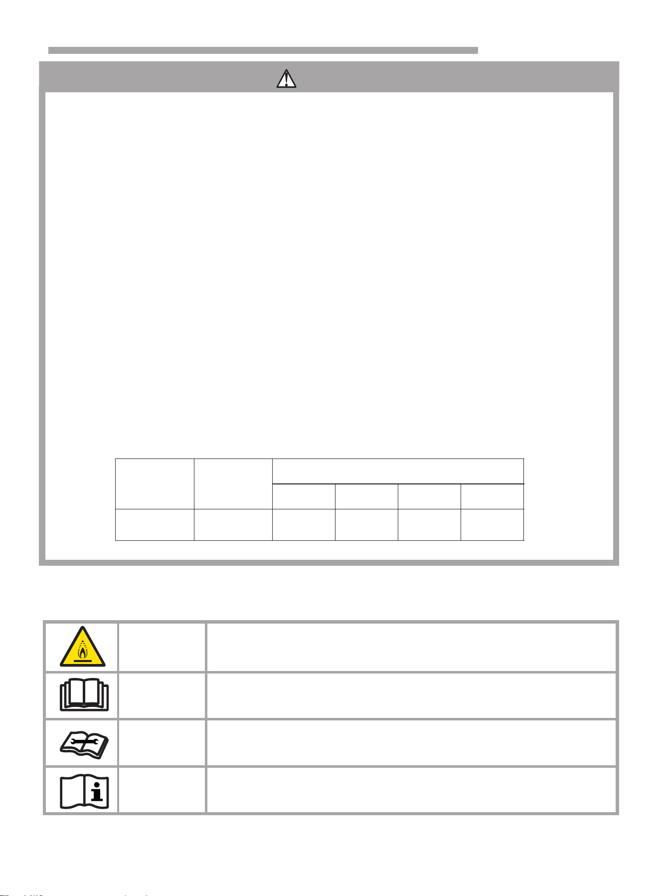
Explanation of symbols displayed on the indoor unit or outdoor unit.
WARNING
This symbol shows that this appliance uses a flammable refrigerant.
If the refrigerant is leaked and exposed to an external ignition source,
there is a risk of fire.
CAUTION
This symbol shows that the operation manual should be read
carefully.
CAUTION
This symbol shows that a service personnel should be handling this
equipment with reference to the installation manual.
CAUTION
This symbol shows that information is available such as the operating
manual or installation manual.
Safety Precautions
Series
Model
(Btu/h)
Installation height (m)
Multi-split
9K/24K
111
40
12
8
2
Required minimum room area X (m )
0.6
1.0
1.8
2.2
8
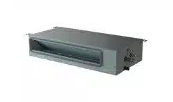
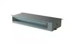
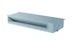
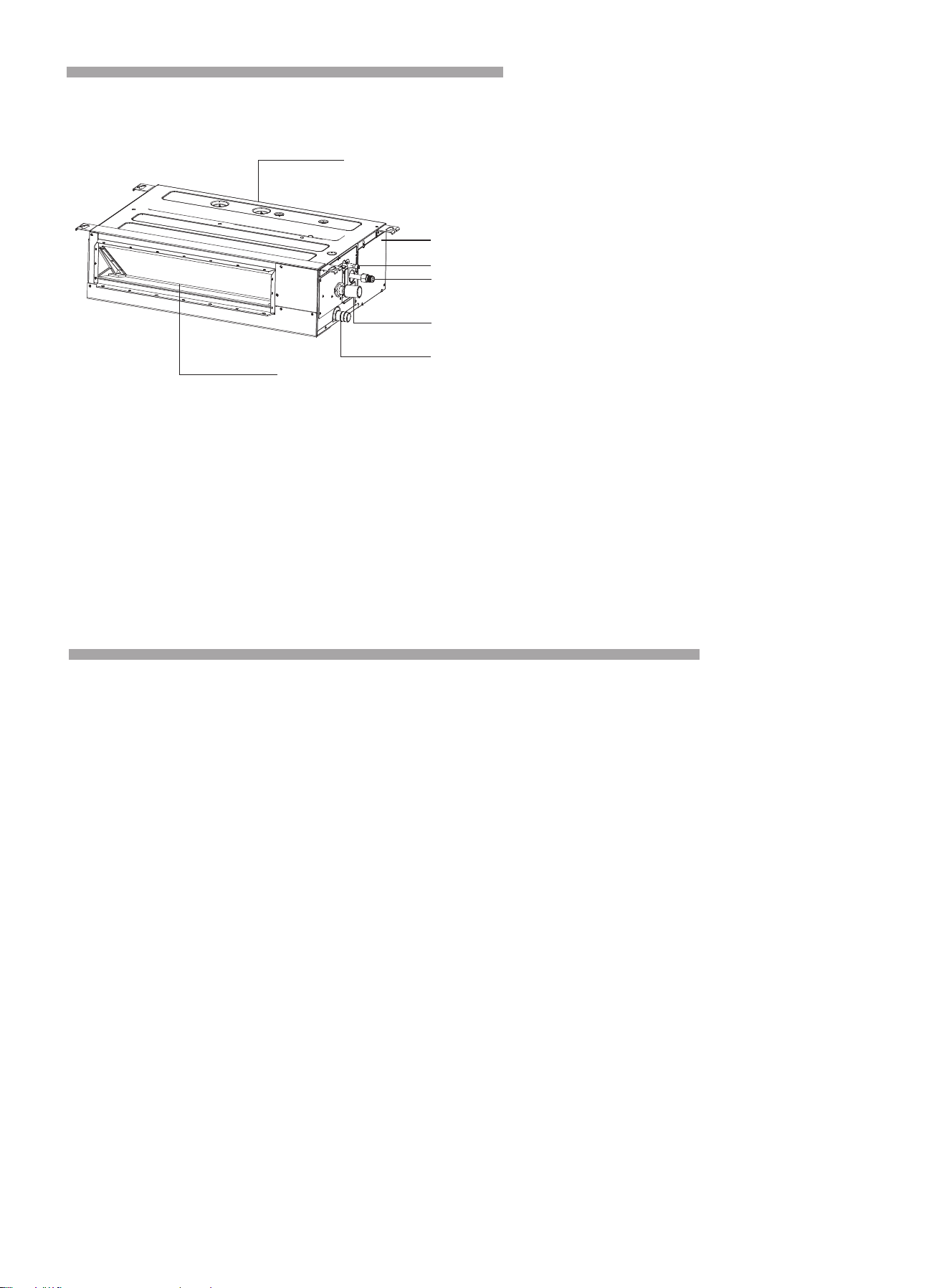
Composition of the Air conditioner
Indoor unit
NOTE: The figures are based on the external views of the standard model.
Consequently,the shape may differ for the air conditioner model you have selected.
Description:
1. Air inlet
2. Electric box
3. Refrigerant pipe (Liquid)
4. Refrigerant pipe (Gas)
5. Drain Pipe (Connect with pump)
6. Drain Pipe
7. Air Outlet
Before Operation
Special Remarks
3-minute protection after the compressor stops•
To protect compressor, the system implements 3 minutes once operation is stopped.
5 minute-protection•
Compressor must run for at least 5 minutes once operation starts. During the 5 minutes, compressor will not
stop even after set point is reached. The system will shut off if manually turned off using the remote controller.
Cooling operation •
The fan of the indoor unit will never stop running in cooling operation. It continues to operate even if the
compressor stops working.
• Heating operation
Heating capacity depends on external factors like outdoor unit temperature. Heating capacity might decrease
if outdoor ambient temperature is too low.
• Anti-freezing function during cooling
When the air temperature from the indoor outlet is too low, the unit will run for some time under the fan mode,
to avoid frost or ice forming on the indoor heat exchanger.
Cold air prevention•
Within several minutes after the heating mode is selected, the fan of the indoor unit will not run until the heat
exchanger of the indoor unit reaches a certain temperature to prevent cold draft.
• Defrosting
When the outdoor temperature is too low, ice may form on the outdoor heat exchanger, reducing heating
performance. When this happens, the defrost cycle of the system will start. During the defrost cycle, the indoor
unit fan stops (or runs at a very low speed in some cases), to prevent cold draft.
Once the defrost cycle is complete, heating operation and the fan speed resume.
1
7
2
3
4
5
6
You can control the air conditioner with the wired remote controller or wireless remote controller.
It is used for controlling power ON/OFF,setting the running mode, temperature, fan speed and other functions.
There are different types of remote controllers that can be used.
Operation instructions will be further specified in remote controller's manual.
Please read it carefully before using this appliance and keep it for future reference.
Remote Controller(Optional)

9
Operation Manual
Discharging the residual heating air•
When stopping the air conditioner in normal operation, the fan motor will run with low speed for a while to
blow out the residual hot air.
• Auto restart from power outage
When the power supply is recovered after power outage, all presets still be in effect and the system will
run according to the previous settings.
3. Not Cooling or Heating Properly
• Check for obstruction of air flow in outdoor or indoor units.
• Check if there are too many heating sources in the room.
Check if the air filter is clogged with dust. •
Check if the doors or windows are open. •
Check if the temperature condition is within the operation range. •
Troubleshooting
If Trouble issue persists... 1.
If the trouble issue persists even after checking the following, contact qualified, licensed service provider,
and inform them of the following items.
(1) Unit Model Name
(2) Details of the issue
2. No Operation
Check if there's power and the unit is turned ON.
Check whether the SET TEMP is set at the correct temperature.
CAUTION
When drain water overflows from the indoor unit, stop the operation and contact your dealer.
When you smell or see white smoke coming out of the unit, turn OFF the main power supply and
contact your dealer.
4. This is Not Abnormal
Odor from Indoor Unit •
Unpleasant odor diffuses from indoor unit after a long period of time. Clean the air filter and panels
or allow a good ventilation.
Sound from Deforming Parts •
During system starting or stopping, a sound might be heard. However, this is due to thermal normal wear of
plastic parts. It is not abnormal.
Steam from Outdoor Heat Exchanger •
During defrosting operation, ice on the outdoor heat exchanger melts resulting in steam.
Dew on Air Panel •
When the cooling operation continues for a long period of time under high humidity conditions, dew may
form on the air panel.
Refrigerant Flow Sound •
While the system is being started or stopped, the refrigerant flow sound may be heard.
10
5. Mode Interfere
Multi-zone outdoor units can only support a single mode at one time (cooling or heating).
When the mode set at one or more indoor unit is different from the mode that outdoor unit is using, mode
interfere will occur.
Outdoor unit always run with the mode of first indoor unit that turned on. When the setting mode of
following indoor unit is interfered with it, 3 beeps would be heard, and the indoor unit interfered with the
normal running units would turn off automatically.
If auto mode is selected, the actual running mode of the unit will be dominated by the unit of which first
select auto mode. (Auto mode is invalid for some models.)
Operation Manual
Mode interfere
Cooling
Cooling
Dry
Dry
Heating
Heating
Fan
Fan
Normal
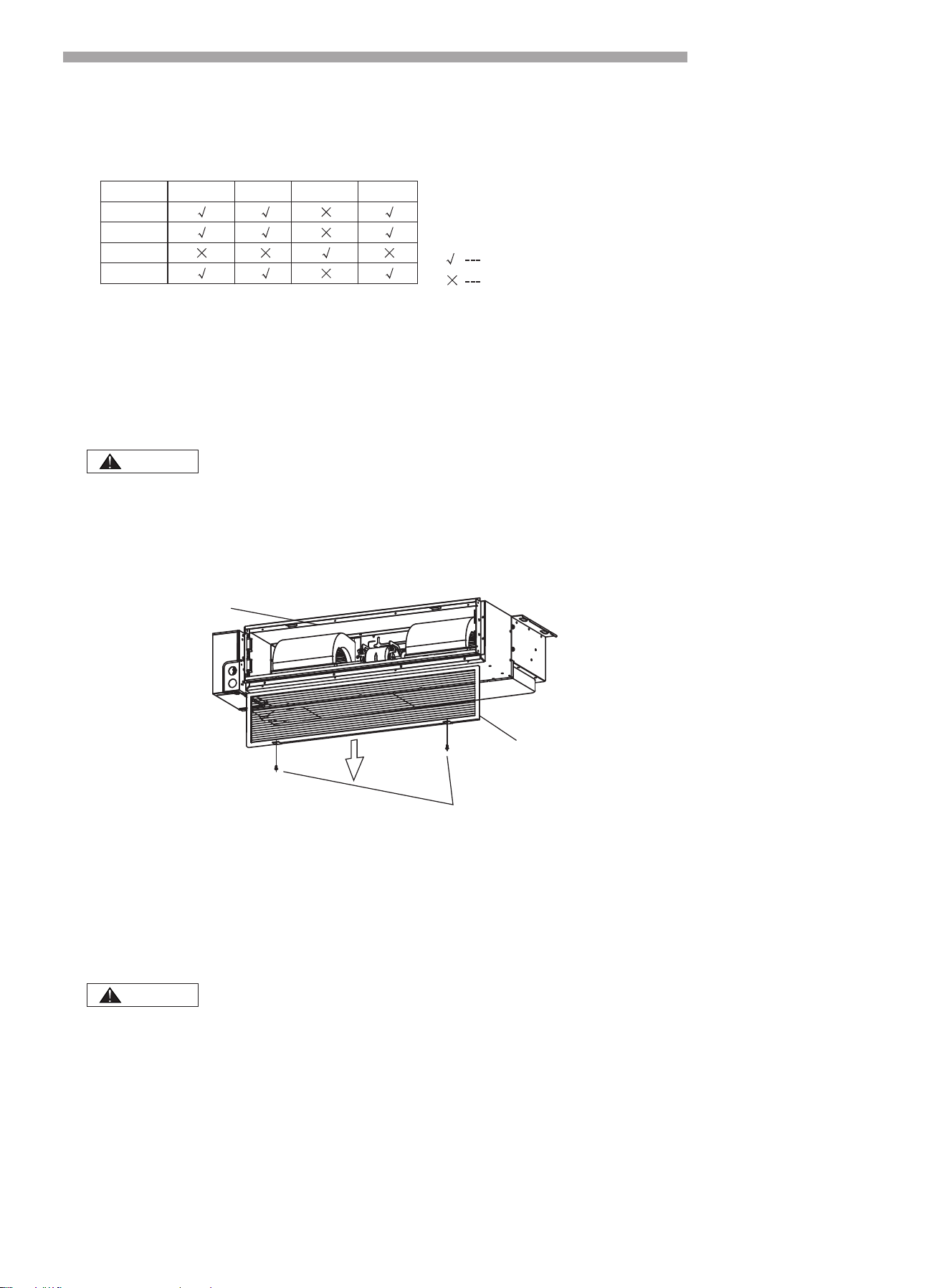
Filter Cleaning
Turn OFF the main power switch before taking filter.
1. Take Out the Filter
2. Clean the Filter
Do not use hot water with temperature more than 40℃.
Do not use light oil essence, diluent, powder or other similar solvents for cleaning.
Air filter can remove dust or other particles in the air, if blocked, the performance of
air conditioner will be greatly reduced. Therefore, in long-term use, you must always
clean the air filter.
If the indoor machine is installed in the place with more air dust, the frequency of
cleaning the air filter should be increased.
Screws
Air filter
Air inlet flange
Remove the fixed screws of the filter and pull the filter down along the rail of the flange as the figure below.
Clean the air filter with a vacuum cleaner or clean water.
1) Use a vacuum cleaner with the air inlet side facing the nozzle of the vacuum.
2) Use clean water with air inlet side turning backward the faucet.
If there is more dirt on the air filter, please use a soft brush and neutral detergent to clean and then dry
the water and set it in a cool place to dry.
.
3. Reinstall the filter
Reinstall the air filter in the reverse order of the filter take out described above.
CAUTION
CAUTION
1. Safety Notice
11
Installation and Maintenance
WARNING
Do not install the air conditioner in a place where there is danger of exposure to inflammable gas leakage.
(If the gas leaks and builds up around the unit, it may catch fire).
Establish drain piping according to the instructions in this manual. (Inadequate piping may cause flooding).
Tighten the flare nut according to the specifications with a torque wrench. (If the flare nut is tightened beyond
specified torque, the flare nut may crack after a long time and cause refrigerant leakage).
CAUTION
Installation should be performed by a qualified personnel. (Improper installation may cause water leakage,
electrical shock or fire.)
Install the unit according to the instructions given in this manual. (Incomplete installation may cause water
leakage, electrical shock or fire).
Be sure to use the supplied or specified installation parts. (Use of other parts may cause the unit to get
loosened, water leakage, electrical shock or fire).
Install the air conditioner on a solid base that can support the unit weight. (An inadequate base or incomplete
installation may cause injury if the unit falls off the base).
Electrical work should be carried out in accordance with the installation manual and the local national
electrical wiring rules or code of practice. (Insufficient capacity or incomplete electrical work may cause
electrical shock or fire).
Be sure to use a dedicated power circuit. (Never use a power supply shared by another appliance).
For wiring, use a cable long enough to cover the entire distance. Do not use an extension cord.
Do not put other loads on the power supply, use a dedicated power circuit.
Use the specified types of wires for electrical connections between the indoor and outdoor units. (Firmly
clamp the interconnecting wires so their terminals receive no external stresses).
Incomplete connections or clamping may cause terminal overheating or fire.
After connecting all the wires be sure to fix the cables so that they do not put undue force on the electrical
covers or panels. (Install covers over the wires, incomplete cover installation may cause terminal overheating,
electrical shock or fire).
When installing or relocating the system, be sure to keep the refrigerant circuit free from air (Air in the
refrigerant circuit may causes an abnormal pressure rise or rupture, resulting in injury).
If any refrigerant has leaked out during the installation work, ventilate the room.
After all installation is completed, check to make sure that no refrigerant is leaking out. (The refrigerant
produces a toxic gas if exposed to flames).
When carrying out piping connection, take care not to let air substances other than the specified refrigerant
get into refrigeration cycle. (Otherwise, it will cause lower performance, abnormal high pressure in the
refrigeration cycle, explosion and injury).
Make sure that the installation is properly grounded. Do not ground the unit to a utility pipe, lightning arrester,
or telephone grounding. Incomplete grounding may cause electrical shock. (A high surge current from
lightning or other sources may cause damage to the air conditioner).
An earth leakage circuit breaker may be required depending on the site condition to prevent electrical shock.
Disconnect the power supply before wiring, piping, or checking the unit.
When moving the indoor unit and outdoor unit, please be careful, do not make the outdoor unit incline over
45 degree. Pay attention to the sharp edges of the air conditioner to avoid any injury.
During wired controller installation, ensure that the length of the wire between the indoor unit and wired
controller is within 40 meters.
●
●●
●●
●
●
●
●
●
●
●
●
●
●
●
●
●
●
●
●
●
●
●
●
3. Installation of the Indoor Unit
12
Installation and Maintenance
CAUTION
2. Tools and Instruments for Installation
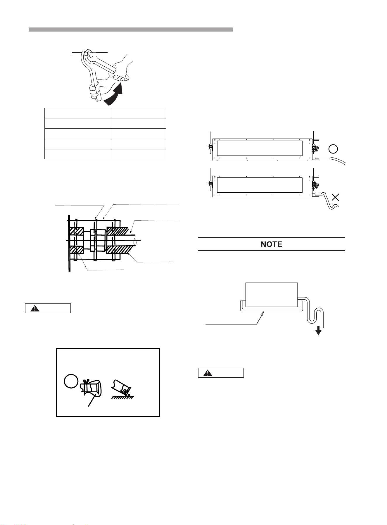
3.1 Initial Check
When moving the unit after unpacking, make sure to lift it by holding its lifting lugs. Do not exert any pressure
on other parts, especially the refrigerant piping, drain piping and flange parts.
Wear protective gears when installing the unit.
CAUTION
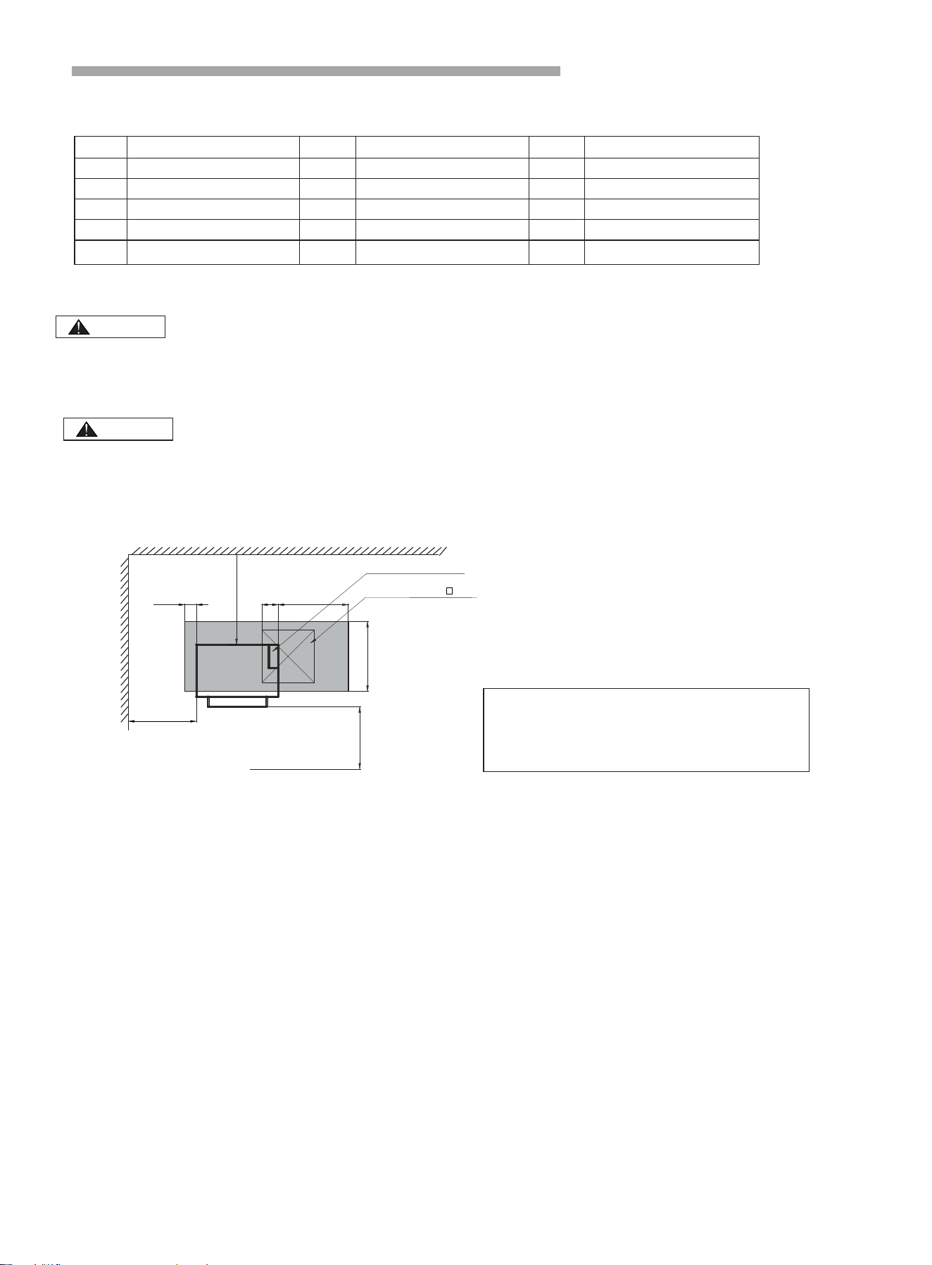
Fig. 3.1.1
(unit:mm)
During installation, do not damage the insulation material on the surface of the indoor unit.
1.Reserve necessary maintenance port when the
ceiling is not detachable.
2.The location of the maintenance port should
ensures remove electric box cover and internal
components are all easy to perform.
≥600
≥
1000
≥
1000
100
140
600
Electric control box
Top view
Maintenance port( ≥450)
600
●
●
Number
1
2
3
4
5
6
7
Tool
Standard screwdriver
Vacuum pump
Charge hose
Pipe bender
Adjustable wrench
Pipe cutter
Cross head screw-driver
Number
Number
8
9
10
11
12
13
14
Tool
Tool
Leveler
Hammer
Churn drill
Knife or wire stripper
Pipe expander
Inner hexagon spanner
Measuring tape
·Optimum air distribution is ensured.
·The air passage is not blocked.
·Condensate can drain properly.
·The ceiling is strong enough to bear the weight of the
indoor unit.
·A false ceiling does not seem to be at an incline.
·Sufficient clearance for maintenance and servicing
is ensured.(See Fig.3.1.1 )
·Piping between the indoor and outdoor units is within
the allowable limits.(refer to the installation of the
outdoor unit )
·The indoor unit, outdoor unit, power supply wiring
and transmission wiring must be kept at least 1m
away from televisions and radio, this prevents image
interference and noise in electrical appliances.
(Noise may be generated depending on the conditions
under which the electric wave is generated, even if a
one-meter allowance is maintained.)
·Do not install the indoor unit in a machinery shop or
kitchen where vapor from oil or its mist flows to the
indoor unit. The oil will deposit on the heat exchanger,
thereby reducing the performance of the indoor unit,
and may deform and in the worst case, break the
plastic parts of the indoor unit.
Use suspension bolts to install the unit, check whether ·
or not the ceiling is strong enough to support the
weight of the unit. If there is a risk that the ceiling is
not strong enough, reinforce the ceiling before
installing the unit.
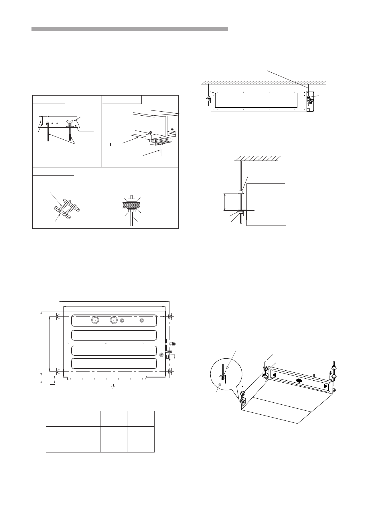
3.2 Installation
3.2.1 Suspension bolts
(1) Consider the pipe direction, wiring and maintenance
carefully, and choose the proper direction and location
for installation.
(2) Install the suspension bolts as shown in Fig. 3.2
below.
Fig. 3.2.1 Fixing the suspension bolts
·For the concrete ·For the steel beam
·For the wooden beam
150 to160mm
Screw in
(100 to150kg)
Steel bar
Concrete
Suspension bolts
(W3/8 or M10)
“ ” shaped steel beam
Wood rib
( )60mm to 90mm
Wooden beam
Nut Round washer
Square washer
Suspension bolts
3.2.2 The position of the suspension bolts and the pipes
(1) Mark the positions of the suspension bolts, the
positions of the refrigerant pipes and the drain pipes.
(2) The dimension are shown below.
Installation and Maintenance
Suspension bolts
(W3/8 or M10)
Nut
.1
Fig. 3.3 Suspension bolts
(Unit:mm)
Air outlet
a
375
b
8
447
27
3.2.3 Install the indoor unit.
The installation of the indoor unit is shown in Fig. 3.4.
(1) How to fix the suspension bolts and the nuts
As shown in the figures 3.5, the nuts are fixed four
bolts.
Suspension bolts (4-M10 or W3/8)
( Field supplied )
Nuts and
washers (4-
M1 0 or W3/ 8)
( Field supplied )
Fig. 3.4 The installation of the indoor unit
Nut
Indoor unit
Washer
Double nut
Fig. 3.5 Suspension bolts and nuts
Approx 50mm
Model
(Btu/h)
a
b
9K
24K
751
700
1231
1180
(2) Install the indoor unit
As shown in the following figure, place the left hanger
bracket on the nuts and washers of the suspension
bolts.
Make sure that the left hanger bracket has been fixed
on the nuts and washers securely, install the right
hanger bracket suspension hook on the nuts and
washers.
(When installing the indoor unit, you can slightly
remove the suspension bolts.)
Rack
Double nuts
and washers
Hanger bracket
Suspension bolt
Indoor unit
Fig. 3.6
●
●
13
Installation and Maintenance
3.2.4 Adjusting of the unit level
(1) Check to ensure that the foundation is flat, taking
into account the maximum foundation gradient.
(2) The unit should be installed that the drainage side
is slightly (0mm~5mm) lower than other sides for
adequate drainage.
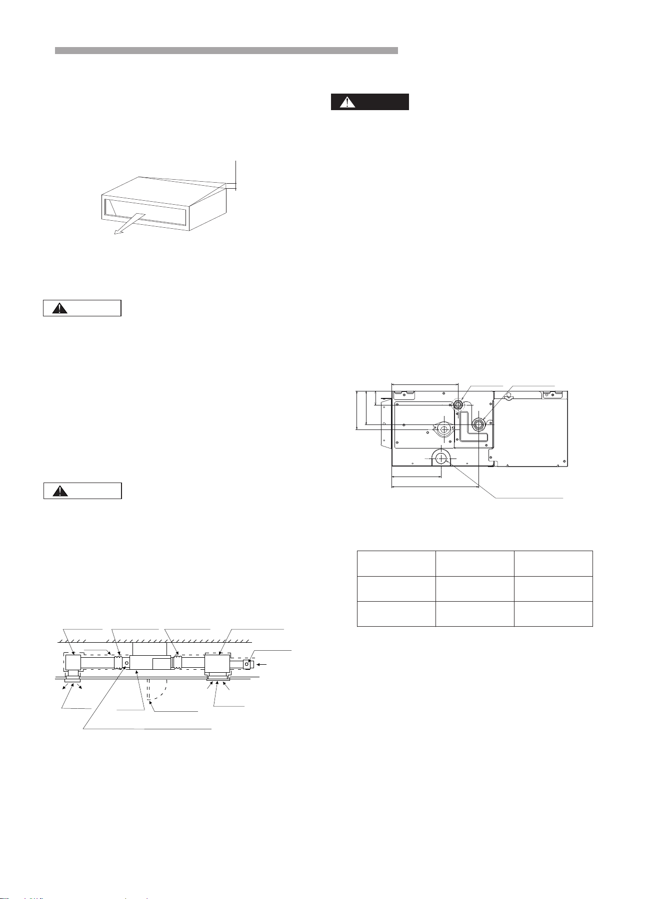
3.2.5 Installing the duct
Make sure the external static pressure of the unit is
within the range.
Connect the duct and intake-side flange.
Connect the duct and outlet-side flange.
The connection of indoor unit and air duct must be
well sealed and kept warm with insulation material.
<Example>
CAUTION
Canvas duct
Horizon
Service mouth
Air inlet
(with filter)
(600mm·600mm)
Air-outlet
The valve for the amount of air
Insulation material
Outside air
(through
the filter)
Static pressure
box
Canvas duct
Static pressure
box
The valve for
the amount of air
(3) After the adjustment, tighten the nuts and swear the
thread locker on the suspension to prevent the nuts
from loosening.
(1) During the installation, please cover the unit with the
plastic cloth to keep it clean.
(2) Make sure that the unit is installed level by using a
level or a plastic tube filled with water in instead of a
level, adjust the top surface of the unit to the surface
of the water at both ends of the plastic tube and
adjust the unit horizontally.(one thing to watch out for
in particular is if it is installed so that the slope is not
in the direction of the drain piping, as this might
cause leaking.)
CAUTION
Fig. 3.7
5m
m
●
●
●
●
4. Refrigerant Pipe
Use the refrigerant according to outdoor nameplate.
When carrying on the leakage check and test, do not
mix in the oxygen, the acetylene and flammable and
the virulent gas, for these gases are quite dangerous,
and may possibly cause explosion. It is suggested
that the nitrogen be used to perform these experiments.
4.1 Pipe Material
(1) Prepare the copper pipe on the spot.
(2) Choose dustless, non-humid, clean copper pipe.
Before installing the pipe, use nitrogen or dry air to
blow away the tube dust and impurity.
(3) Choose the copper pipe according to Fig. 4.2.
4.2 Connection of the Pipe
(1) The connection positions of the pipe are shown in
Fig. 4.1 and Fig. 4.2.
Fig. 4.2 The pipe diameter
DANGER
(unit:mm)
Model
(Btu/h)
Gas Pipe
Liquid Pipe
9K
φ9.52
φ6.35
24K
φ15.88
φ9.52
Fig. 4.1 The connection positions of the pipe
Ref. gas pipe
Ref. liquid pipe
Drain pipe
166
129
220
97
86
35
NOTE:
If the diameter of connection pipe does not match the port
size of the outdoor unit, a different-diameter joint can be
used instead.
14
15
(2) As shown in Fig. 4.3, screw up the nuts with 2 spanners.
Installation and Maintenance
The pipe goes through the hole with the end sealed.
CAUTION
Do not put the pipes on the floor directly.
Fig. 4.3 Tightening torque for the nut
φ6.35mm
φ9.52mm
φ12.7mm
φ15.88mm
Tube size
20
40
60
80
Torque (N·m)
Protected with the tape or plug.
(3) After finishing connecting the refrigerant pipes, keep
it warm with the insulation material.
Fig. 4.4 Piping insulation procedure
Clamp(field supplied)
Insulation(field supplied)
Refrigerant pipe
(field supplied)
Side of the
indoor unit
Insulation
(field supplied)
Insulation
(field supplied)
Insulation
(field supplied)
●
●
Correct
Incorrect
×
5. Drain piping
Install the drain piping
Make sure the drain works properly .
Prepare polyvinyl chloride pipe with a 32mm outer
diameter.
The diameter of drain pipe connection hole should
be same as that of the drain pipe.
Keep the drain pipe short and sloping down wards at
a gradient of at least 1/100 to prevent air pockets from
forming.
Water accumulating in the drain piping can cause
the drain to clog.
CAUTION
When the relative humidity of inlet or ambient air
exceeds 80%,apply an (field-supplied) auxiliary
drain pan beneath the indoor unit as shown below.
Indoor Unit
To the Atmosphere
(Field-Supplied)
Auxiliary Drain Pan
●
●
●
●
●
●
●
To keep the drain tube from sagging, space hanging
wires every 1 to 1.5 m.
Use the drain hose and the clamp. Insert the drain
hose fully into the drain socket and firmly tighten the
drain hose and warm-keeping material with the clamp.
The two areas below should be insulated because
condensation may happen there causing water leakage.
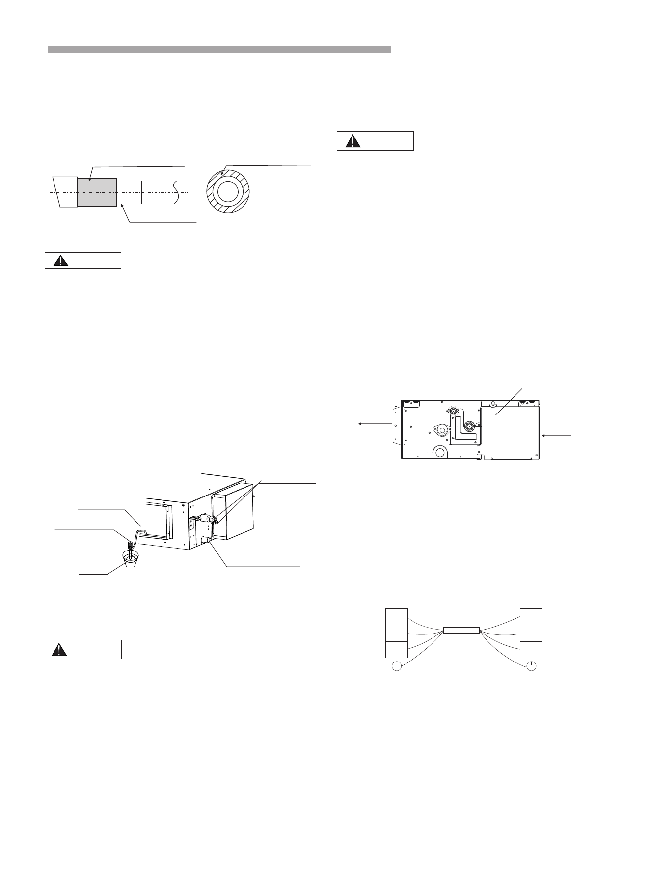
16
Refrigerant
pipes
Bucket
Portable pump
Air outlet
Drain outlet
Installation and Maintenance
CAUTION
Drain piping passing indoors
Drain sockets.
Referring the figure below, insulate the drain socket
and drain hose.
Drain piping connections
Do not connect the drain pipes directly to sewage pipes
to avoid ammonia odor. The ammonia in the sewage
might enter the indoor unit through the drain pipes
and corrode the heat exchanger.
Do not twist or bend the drain hose, doing so applies
excessive force applied on it and may also cause
leakage.
After piping work is finished, check if drainage flows
smoothly.
Gradually pour approximately 1000 cc of water from
the outlet hole into the drain pan to check drainage flow.
Check the drainage as shown below:
Drain hose
Sealing material Sealing material
●
●
●
●
●
●
●
If the fuses blow, please call the authorized service dealer.
Please do not replace it by yourself, as it may result in
accident or electric shock.
(1) As shown in Fig. 6.1, remove the screws on the
control box.
(2) Connect the power cord and ground wire to the main
terminal.
(3) Connect the remote control wire to the subsidiary
terminal box.
(4) Connect the power supply of the indoor and outdoor
units to the main terminal.
(5) Tie the wire in the control box with the clamp tightly.
(6) After completing the wiring, seal the wiring hole with
the sealing material (with the lid) to prevent the
condensation and insects entering the control box.
WARNING
6. Electrical Wiring
least 50 mm so that they do not pass through the same
place together. Proximity may cause electrical
interference malfunction and breakage.
When clamping the wiring, use the included clamping
material as shown in Fig.6.1 to prevent external
pressure being exerted on the wiring connections and
clamp firmly.
While performing wiring work, make sure the wiring
is proper and does not cause the control box lid to
stick up, then close the cover firmly. When attaching
the control lid, make sure you do not pinch any wires.
Outside the indoor unit and outdoor unit, separate the
weak wiring (remote controller and transmission wiring)
and strong wiring (ground and power supply wiring) at
CAUTION
6.1 General Check
●
●
●
Remove the screws on the control box
Fig.6.1
Electrical Wiring Diagram
Outdoor unit
Indoor unit
Terminal
Terminal
4(SI)
SI
1(L)
L
2(N)
N
Transmitting cable
The lid of the control box
Air inlet
Air outlet
Installation and MaintenanceInstallation and Maintenance
17
Model
( Btu/h)
The range of
ESP
Function code set
9K
0-30Pa
0-30, function code value equals
static pressure value
[default: 10 (10Pa)]
24K
0-40Pa
0-40, function code value equals
static pressure value
[default: 40 (40Pa)]
If you still have any trouble, please contact local technical service center of our company for further information.
The ESP can be freely adjusted by using specific wired remote controller.
Note: The pressure loss of filter is not included in the ESP data above.
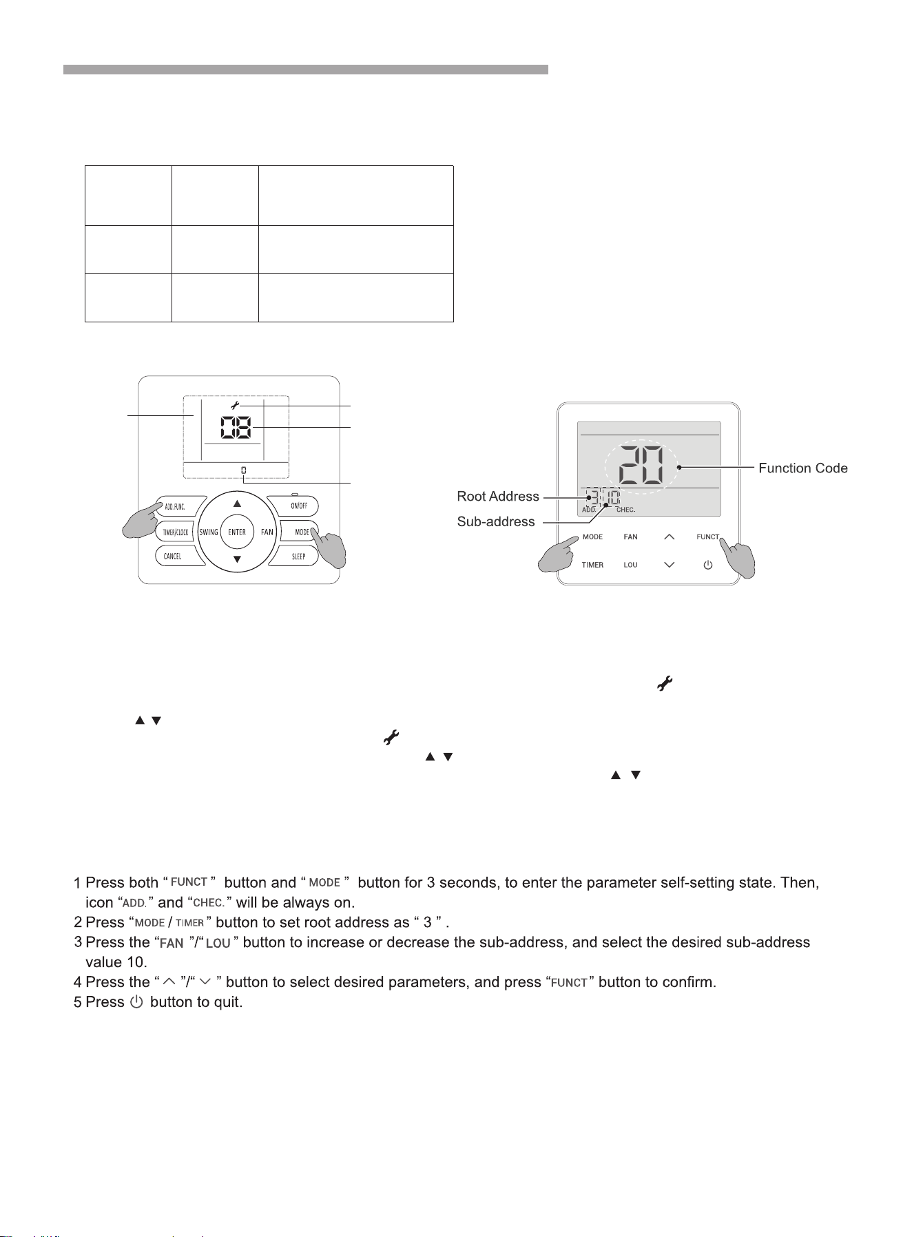
6.2 Change of ESP (External Static Pressure)
ESP setting (C-Series wired controller):
Press and hold “MODE” button and “ADD.FUNC.” button for 3 seconds, symbol and parameter code
starts blinking at the same time.
Press“ / ”button to adjust parameter number until “17” is displayed, and press “ENTER” button to enter
system parameter adaption state, symbol stops blinking.
Select desired parameter code 10 by pressing “ / ” button, and press "ENTER" button to confirm.
Select desired function code to rewrite the parameter values by pressing “ / ”button, and press
"ENTER" button to confirm.
Press “ON/OFF” button or “CANCEL”button to quit.
ESP setting (E-Series wired controller):
Parameter
Code
LCD
Function Code
Error Indicator
1
2
3
4
5
Fig 6.2
C-Series wired controller E-Series wired controller
Installation and Maintenance
6.3 Electrical Installation
● Use an ELB (Electric Leakage Breaker). If not used, it will cause an electric shock or a fire.
● Do not operate the system until all the check points have been cleared.
(A) Check to ensure that the insulation resistance is more than 2MΩ, by measuring the resistance between
ground and the terminal of the electrical parts. If not, do not operate the system until the electrical leakage
is found and repaired.
(B) Check to ensure that the stop valves of the outdoor unit are fully opened and then start the system.
Pay attention to the following items while the system is running.
Do not touch any of the parts by hand at the discharge gas side, since the compressor chamber and the
pipes at the discharge side are heated higher than 90℃.
18
Model
Transmission Cable Size
9K/24K
2
4×1.5mm
Max. Running Current(A): REFER TO NAMEPLATE
NOTES:
1) Follow local codes and regulations when selecting field wires.
2) The wire sizes marked in the table are selected at the maximus current of the unit according to the
IEC60335-1, or regional standards.Use the wires which are not lighter than the ordinary
polychloroprene sheathed flexible cord (code designation H07RN-F) .
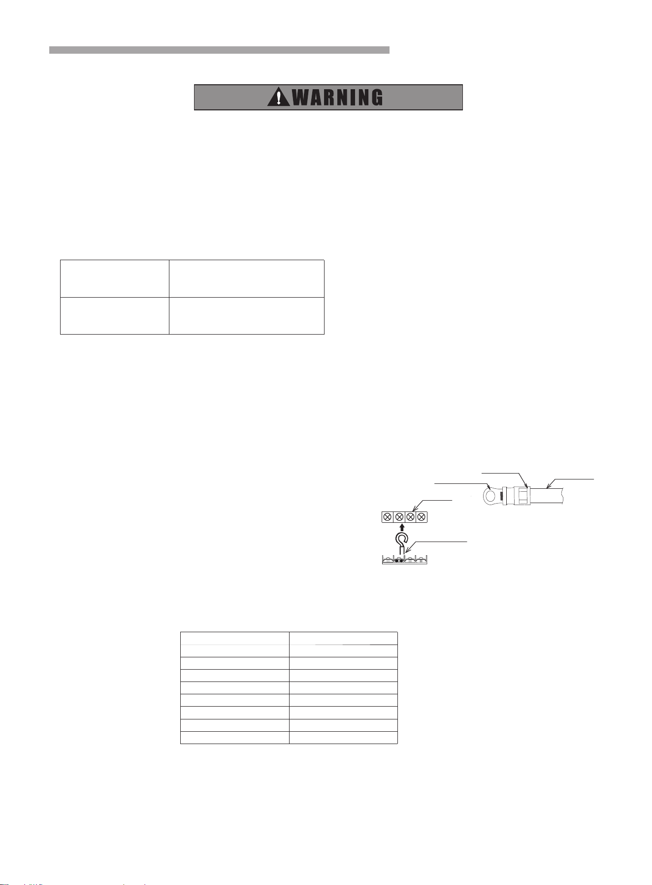
When connecting the terminal block using flexible cord, make sure to use the round crimp-style terminal
for connection to the power supply terminal block.
Place the round crimp-style terminals on the wires up to the covered
part and secure in place.
When connecting the terminal block using a single core
wire, be sure to perform curing.
3) When transmission cable length exceeds 15 meters, a larger wire size should be selected.
4) Use a shielded cable for the transmitting circuit and connect it to ground.
5) In the case that power cables are connected in series, add each unit maximum current and select wires below.
*In the case that current exceeds 63A, do not connect cables in series.
Flexible cord
covered part
Round crimp-style terminal
Terminal
Single core wire
Current i(A)
2
Wire Size(mm )
i≤6
0.75
6<i≤10 1
10<i≤16 1.5
16<i≤25 2.5
25<i≤32 4
32<i≤40 6
40<i≤63 10
63<i
*
Selection According to IEC60335-1
7. Test Run
Please perform test run according to outdoor unit installation manual.
(Btu/h)
●

Version No. 2285205. A