Installation and Operating Manual
1612 1 100271266
KEEP THIS MANUAL ON (OR NEAR) HEATER FOR FUTURE REFERENCE
WHENEVER MAINTENANCE ADJUSTMENT OR SERVICE IS REQUIRED.
• For Your Safety •
AN ODOURANT IS ADDED TO THE GAS USED
BY THIS WATER HEATER.
Read and understand instruction
manual and safety messages
before installing, operating or
servicing this water heater.
Failure to follow instructions and
safety messages could result in
death or serious injury.
Instruction manual must remain
with water heater.
WARNING
ALL TECHNICAL AND WARRANTY QUESTIONS: SHOULD BE DIRECTED TO THE LOCAL DEALER FROM WHOM THE WATER HEATER WAS PURCHASED.
IF YOU ARE UNSUCCESSFUL, PLEASE CONTACT THE COMPANY LISTED ON THE RATING PLATE ON THE WATER HEATER.
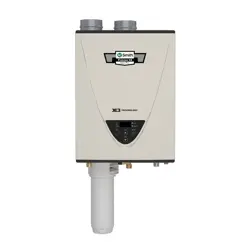
COMMON VENTING TANKLESS GAS WATER HEATERS
- Do not store or use gasoline or other flam-
mable vapours and liquids in the vicinity of
this or any other appliance.
- WHAT TO DO IF YOU SMELL GAS:
• Do not try to light any appliance.
• Do not touch any electrical switch; do not
use any phone in your building.
• Immediately call your gas supplier from a
neighbor's phone. Follow the gas sup-
plier's instructions.
• If you cannot reach your gas supplier, call
the fire department.
- Installation and service must be performed by
a qualified installer, service agency or the
gas supplier.
WARNING: If the information in these instruc-
tions is not followed exactly, a fire or explosion
may result causing property damage, personal
injury or death.
- Do not store or use gasoline or other flam-
mable vapors and liquids in the vicinity of
this or any other appliance.
- WHAT TO DO IF YOU SMELL GAS:
• Do not try to light any appliance.
• Do not touch any electrical switch; do not
use any phone in your building.
• Immediately call your gas supplier from a
neighbor's phone. Follow the gas sup-
plier's instructions.
• If you cannot reach your gas supplier, call
the fire department.
- Installation and service must be performed by
a qualified installer, service agency or the
gas supplier.
WARNING: If the information in these instruc-
tions is not followed exactly, a fire or explosion
may result causing property damage, personal
injury or death.

2 100271266
TABLE OF CONTENTS
Instructions . . . . . . . . . . . . . . . . . . . . . . . . . . . . . . . . . . . 4
Introduction . . . . . . . . . . . . . . . . . . . . . . . . . . . . . . . . . 4
Vent Materials . . . . . . . . . . . . . . . . . . . . . . . . . . . . . . . 4
Vent & Exhaust Installation . . . . . . . . . . . . . . . . . . . . . 5
Condensate. . . . . . . . . . . . . . . . . . . . . . . . . . . . . . . . . 5
Common Vent Types. . . . . . . . . . . . . . . . . . . . . . . . . . 6
Horizontal (Side-By-Side)
Vertical (Multi-Level)
Determining The Common Vent Diameter . . . . . . . . . 8
Horizontal Configuration
Vertical Configuration
Clearances . . . . . . . . . . . . . . . . . . . . . . . . . . . . . . . . . 9
Sidewall Terminations
Rooftop Terminations
Venting Components . . . . . . . . . . . . . . . . . . . . . . . . . . 10
Horizontal Configurations - (Schedule 40 PVC Piping) 10
Back-To-Back
In-Line
Horizontal Configurations - (Polypropylene Piping) . 14
Back-To-Back
In-Line
Vertical Configuration (Schedule 40 PVC Piping) . . . 18
Dual Chase
Single Chase
Vertical Configuration (Polypropylene Piping). . . . . . 22
Dual Chase
Single Chase
Item List. . . . . . . . . . . . . . . . . . . . . . . . . . . . . . . . . . . 30
Final Checklist. . . . . . . . . . . . . . . . . . . . . . . . . . . . . . 30

100271266 3
LIST OF FIGURES
Figure 1. Non-Return Valve (p/n 100113130). . . . . . . . . . . . . . . . . . . . . . . . . . . . . . . . . . . . . . . . . . . . . . . . . . . . . . . . . . .4
Figure 2. PVC Adaptor (p/n 100113129) . . . . . . . . . . . . . . . . . . . . . . . . . . . . . . . . . . . . . . . . . . . . . . . . . . . . . . . . . . . . . .4
Figure 3. Vent Length Dimensioning . . . . . . . . . . . . . . . . . . . . . . . . . . . . . . . . . . . . . . . . . . . . . . . . . . . . . . . . . . . . . . . . .5
Figure 4. Typical Common-Vent Through The Roof Installation. . . . . . . . . . . . . . . . . . . . . . . . . . . . . . . . . . . . . . . . . . . . .6
Figure 5. Typical Common-Vent Through The Wall Installation . . . . . . . . . . . . . . . . . . . . . . . . . . . . . . . . . . . . . . . . . . . . .6
Figure 6. Typical Common-Vent Combination Wall / Roof Installation. . . . . . . . . . . . . . . . . . . . . . . . . . . . . . . . . . . . . . . .6
Figure 7. Vertical Through-The-Roof Venting. . . . . . . . . . . . . . . . . . . . . . . . . . . . . . . . . . . . . . . . . . . . . . . . . . . . . . . . . . .7
Figure 8. Vertical Through-The-Wall Venting . . . . . . . . . . . . . . . . . . . . . . . . . . . . . . . . . . . . . . . . . . . . . . . . . . . . . . . . . . .7
Figure 9. Vertical Venting In A Single Chase . . . . . . . . . . . . . . . . . . . . . . . . . . . . . . . . . . . . . . . . . . . . . . . . . . . . . . . . . . .8
Figure 10. Vent Dimensioning . . . . . . . . . . . . . . . . . . . . . . . . . . . . . . . . . . . . . . . . . . . . . . . . . . . . . . . . . . . . . . . . . . . . . . .8
Figure 11. Vent Dimensioning . . . . . . . . . . . . . . . . . . . . . . . . . . . . . . . . . . . . . . . . . . . . . . . . . . . . . . . . . . . . . . . . . . . . . . .9
Figure 12. Venting Components Horizontal Configuration (Back-to-Back) . . . . . . . . . . . . . . . . . . . . . . . . . . . . . . . . . . . .10
Figure 13. Horizontal Configuration (Back-to-Back). . . . . . . . . . . . . . . . . . . . . . . . . . . . . . . . . . . . . . . . . . . . . . . . . . . . . . 11
Figure 14. Venting Components Horizontal Configuration (In-Line). . . . . . . . . . . . . . . . . . . . . . . . . . . . . . . . . . . . . . . . . .12
Figure 15. Horizontal Configuration (In-Line) . . . . . . . . . . . . . . . . . . . . . . . . . . . . . . . . . . . . . . . . . . . . . . . . . . . . . . . . . . .13
Figure 16. Horizontal Configuration (In-Line on Wall) . . . . . . . . . . . . . . . . . . . . . . . . . . . . . . . . . . . . . . . . . . . . . . . . . . . .13
Figure 17. Venting Components Horizontal Configuration (Back-to-Back) . . . . . . . . . . . . . . . . . . . . . . . . . . . . . . . . . . . .14
Figure 18. Horizontal Configuration (Back-to-Back). . . . . . . . . . . . . . . . . . . . . . . . . . . . . . . . . . . . . . . . . . . . . . . . . . . . . .15
Figure 19. Venting Components Horizontal Configuration (In-Line). . . . . . . . . . . . . . . . . . . . . . . . . . . . . . . . . . . . . . . . . .16
Figure 20. Horizontal Configuration (In-Line) . . . . . . . . . . . . . . . . . . . . . . . . . . . . . . . . . . . . . . . . . . . . . . . . . . . . . . . . . . .17
Figure 21. Horizontal Configuration (In-Line on Wall) . . . . . . . . . . . . . . . . . . . . . . . . . . . . . . . . . . . . . . . . . . . . . . . . . . . .17
Figure 22. Venting Components Vertical Configuration (Dual Chase) . . . . . . . . . . . . . . . . . . . . . . . . . . . . . . . . . . . . . . . .18
Figure 23. Vertical Configuration (Dual Chase) . . . . . . . . . . . . . . . . . . . . . . . . . . . . . . . . . . . . . . . . . . . . . . . . . . . . . . . . .19
Figure 24. Venting Components Vertical Configuration (Single Chase). . . . . . . . . . . . . . . . . . . . . . . . . . . . . . . . . . . . . . .20
Figure 25. Vertical Configuration (Single Chase) . . . . . . . . . . . . . . . . . . . . . . . . . . . . . . . . . . . . . . . . . . . . . . . . . . . . . . . .21
Figure 26. Venting Components Vertical Configuration (Dual Chase) . . . . . . . . . . . . . . . . . . . . . . . . . . . . . . . . . . . . . . . .22
Figure 27. Vertical Configuration (Dual Chase) . . . . . . . . . . . . . . . . . . . . . . . . . . . . . . . . . . . . . . . . . . . . . . . . . . . . . . . . .23
Figure 28. Venting Components Vertical Configuration - Tees (Dual Chase). . . . . . . . . . . . . . . . . . . . . . . . . . . . . . . . . . .24
Figure 29. Vertical Configuration - Tees (Dual Chase). . . . . . . . . . . . . . . . . . . . . . . . . . . . . . . . . . . . . . . . . . . . . . . . . . . .25
Figure 30. Venting Components Vertical Configuration - Wyes (Single Chase) . . . . . . . . . . . . . . . . . . . . . . . . . . . . . . . .26
Figure 31. Vertical Configuration - Wyes (Single Chase). . . . . . . . . . . . . . . . . . . . . . . . . . . . . . . . . . . . . . . . . . . . . . . . . .27
Figure 32. Venting Components Vertical Configuration - Tees (Single Chase) . . . . . . . . . . . . . . . . . . . . . . . . . . . . . . . . .28
Figure 33. Vertical Configuration - Tees (Single Chase) . . . . . . . . . . . . . . . . . . . . . . . . . . . . . . . . . . . . . . . . . . . . . . . . . .29
LIST OF TABLES
Table 1. Allowable Vent Materials. . . . . . . . . . . . . . . . . . . . . . . . . . . . . . . . . . . . . . . . . . . . . . . . . . . . . . . . . . . . . . . . . . .4
Table 2. List of Venting Components Horizontal Configuration (Back-to-Back) . . . . . . . . . . . . . . . . . . . . . . . . . . . . . . . 11
Table 3. List of Venting Components Horizontal Configuration (In-Line) . . . . . . . . . . . . . . . . . . . . . . . . . . . . . . . . . . . .13
Table 4. List of Venting Components Horizontal Configuration (Back-to-Back) . . . . . . . . . . . . . . . . . . . . . . . . . . . . . . .15
Table 5. List of Venting Components Horizontal Configuration (In-Line) . . . . . . . . . . . . . . . . . . . . . . . . . . . . . . . . . . . .17
Table 6. List of Venting Components Vertical Configuration (Dual Chase). . . . . . . . . . . . . . . . . . . . . . . . . . . . . . . . . . .19
Table 7. List of Venting Components Vertical Configuration (Single Chase) . . . . . . . . . . . . . . . . . . . . . . . . . . . . . . . . .21
Table 8. List of Venting Components Vertical Configuration - Wyes (Dual Chase) . . . . . . . . . . . . . . . . . . . . . . . . . . . .23
Table 9. List of Venting Components Vertical Configuration - Tees (Dual Chase) . . . . . . . . . . . . . . . . . . . . . . . . . . . . .25
Table 10. List of Venting Components Vertical Configuration - Wyes (Single Chase) . . . . . . . . . . . . . . . . . . . . . . . . . . .27
Table 11. List of Venting Components Vertical Configuration - Tees (Single Chase) . . . . . . . . . . . . . . . . . . . . . . . . . . . .29
4 100271266
INSTRUCTIONS
INTRODUCTION
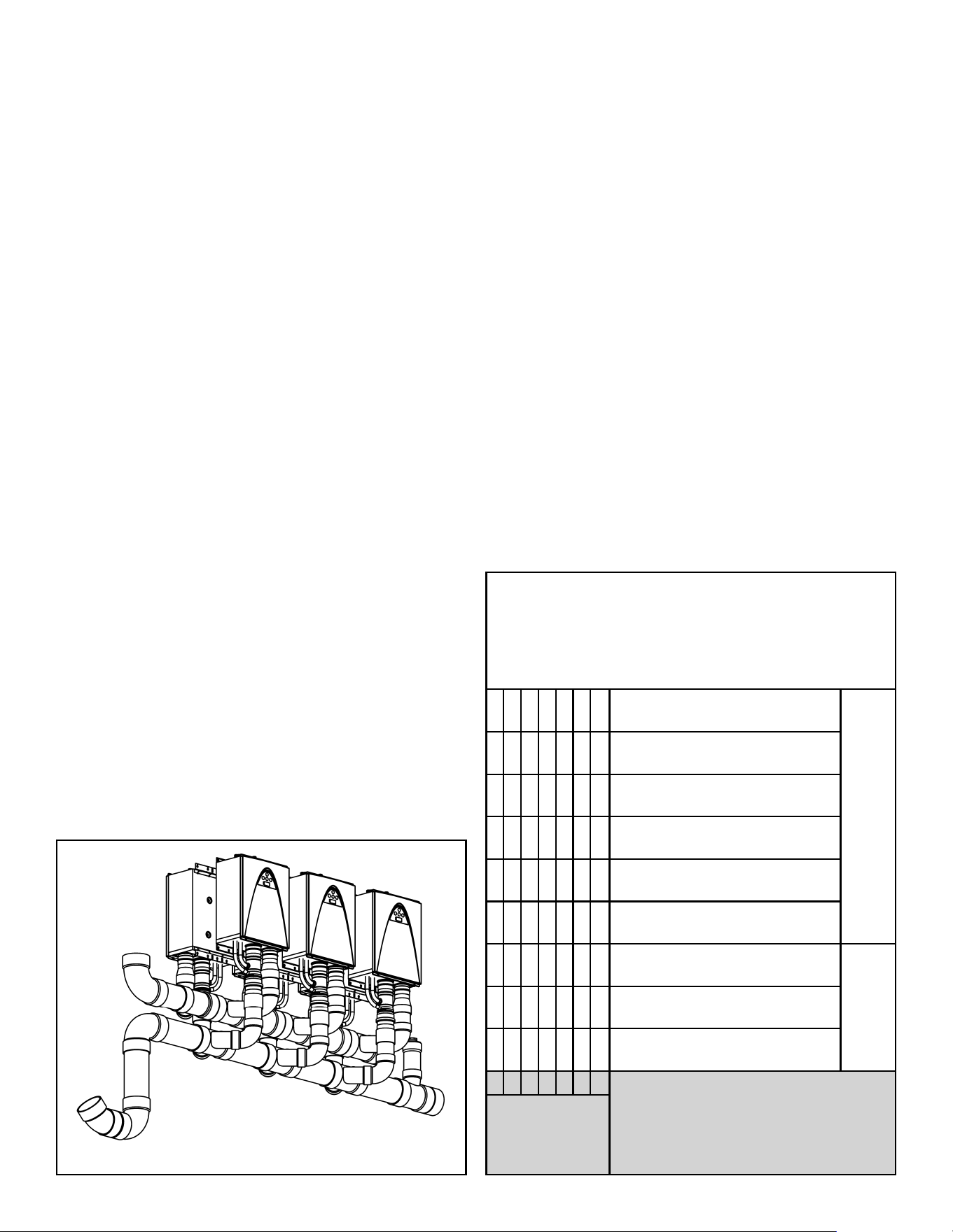
The only heaters approved for common venting are the
condensing heaters: 240 (T-H3J), 340 (T-H3S), and 540
(T-H3). When common vented, the heaters must be direct
vented.
There are two possible configurations for common venting.
One is for multiple heaters installed side-by-side (horizontal
configuration), the other is a multi-level vertical configuration,
like a multi-level apartment building.
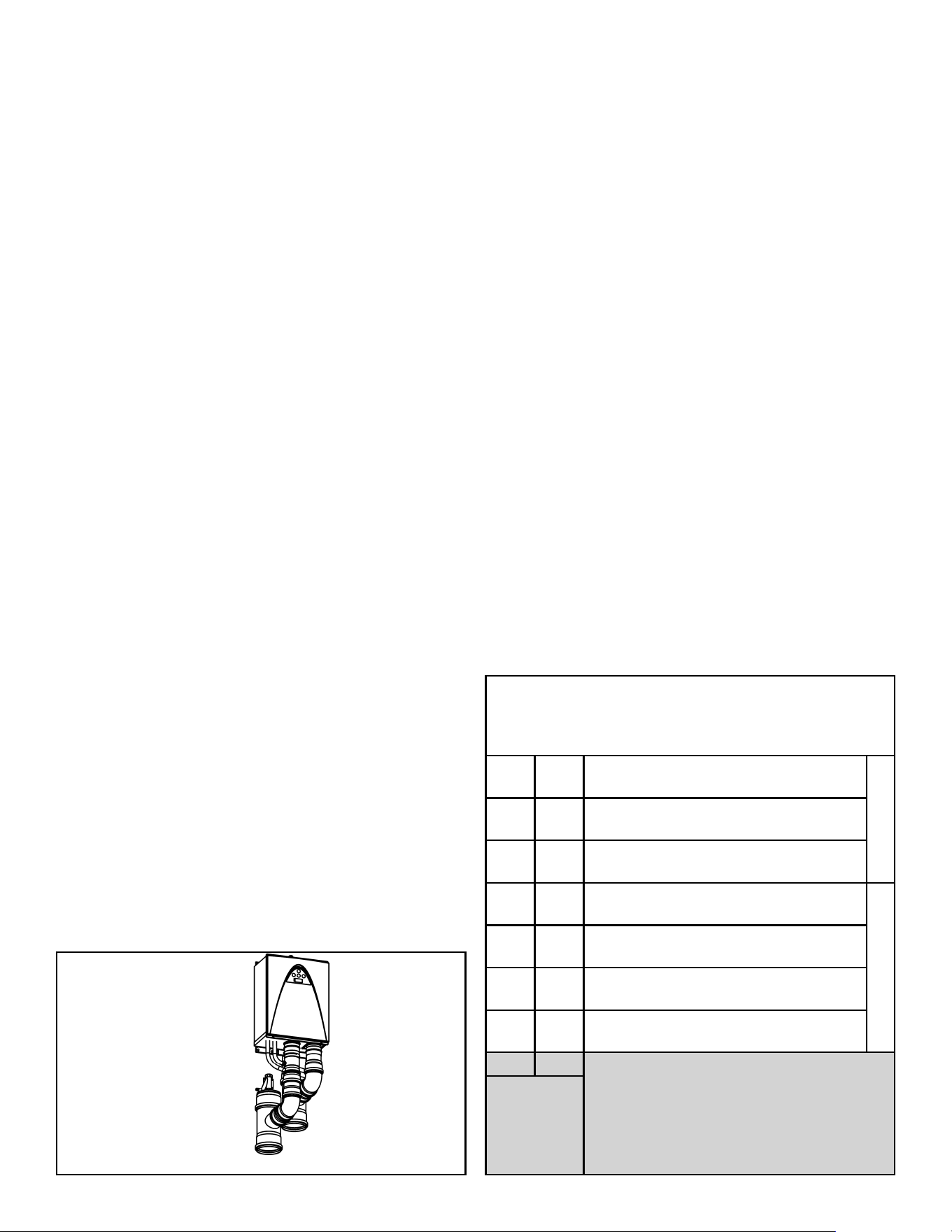
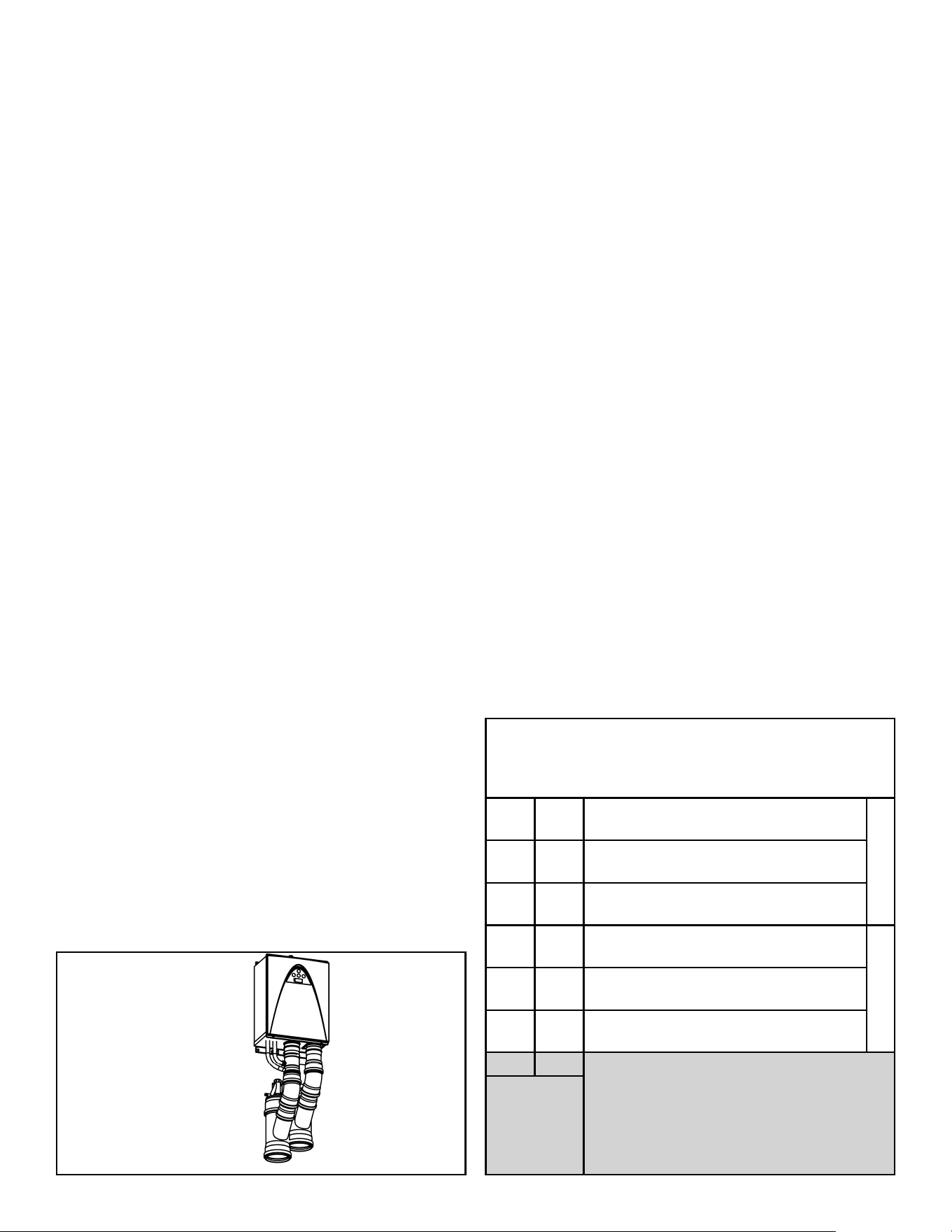
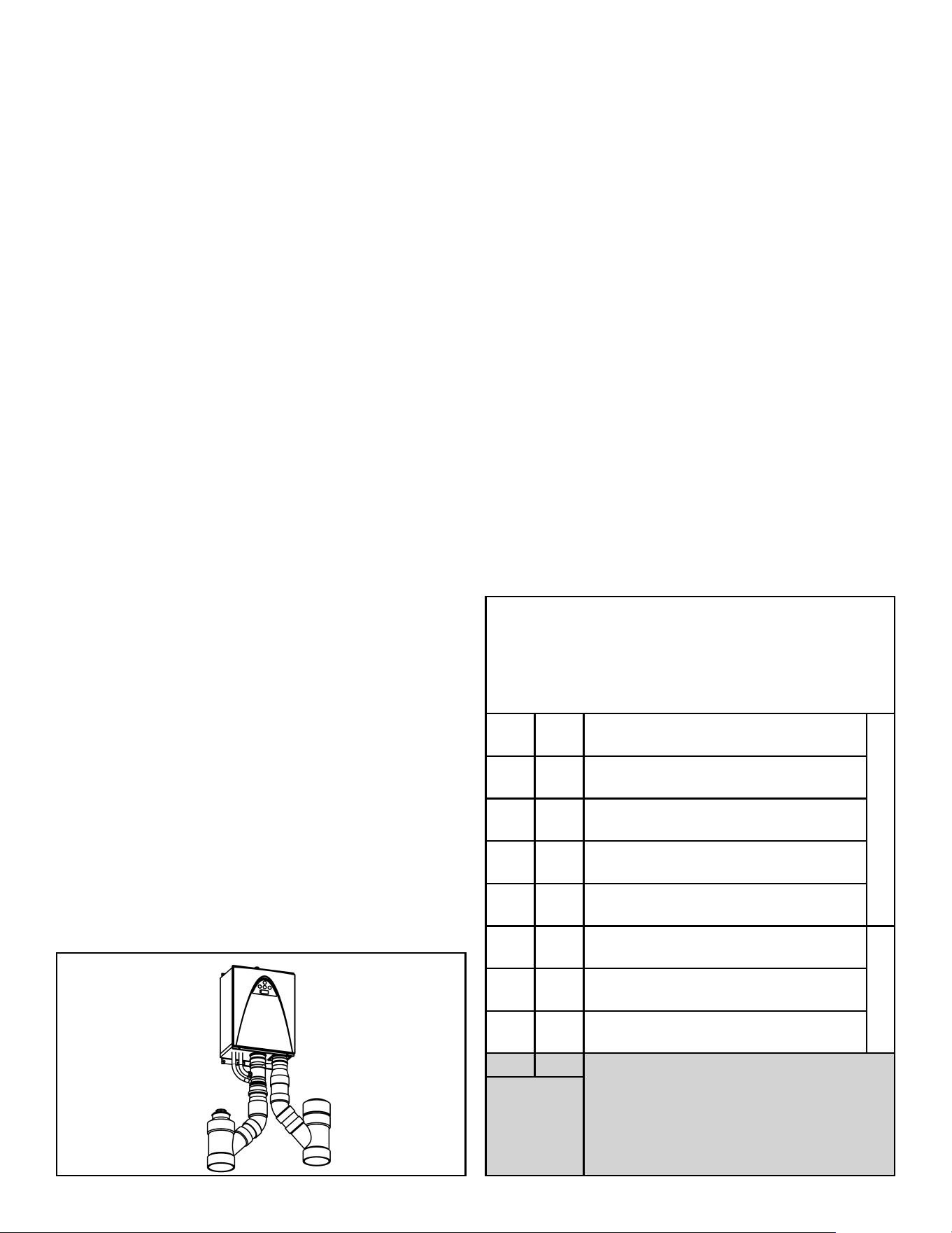
WARNING! Each common vented heater must have a
Non-Return Valve (NRV), p/n 100113130, installed in the
heater’s exhaust. See the instructions packaged with the
NRV for proper installation.
A maximum of 8 heaters may be common vented in a side-
by-side (horizontal) configuration. A maximum of 3 heaters
may be common-vented in a multi-level vertical configuration.
When used in a common vent configuration, each condensing
heater requires the installation of a polypropylene Non-Return
Valve (NRV).
Figure 1. Non-Return Valve (p/n 100113130)
The maximum equivalent vent run is 100 feet. Each 90° elbow
is equivalent to 5 feet of pipe. Each 45° elbow is equivalent to
2.5 feet of pipe. The common vent header should remain the
same size from beginning to the termination. The termination
can be through a sidewall or the roof.
VENT MATERIALS
The following venting materials are allowed to be used for the
exhaust and air intake piping:
1. Schedule 40 PVC piping (Solid Core only).
2. PVC-DWV piping.
3. Schedule 40 CPVC piping (Solid Core only).
4. Schedule 40 ABS piping
5. InnoFlue
®
by Centrotherm (polypropylene vent system).
Item Material
United
States
Canada
Exhaust
pipe and
Fittings
Schedule 40
PVC
ANSI/ASTM
D1785
ULC S636
Certified
Materials
Only
PVC-DWV
ANSI/ASTM
D2665
Schedule 40
CPVC
ANSI/ASTM
F441
Schedule 40
ABS-DWV
ANSI/ASTM
D2661
Polypropylene UL-1738
Pipe
Cement/
Primer
PVC
ANSI/ASTM
D2564
CPVC
ANSI/ASTM
F493
ABS
ANSI/ASTM
D2235
Table 1. Allowable Vent Materials
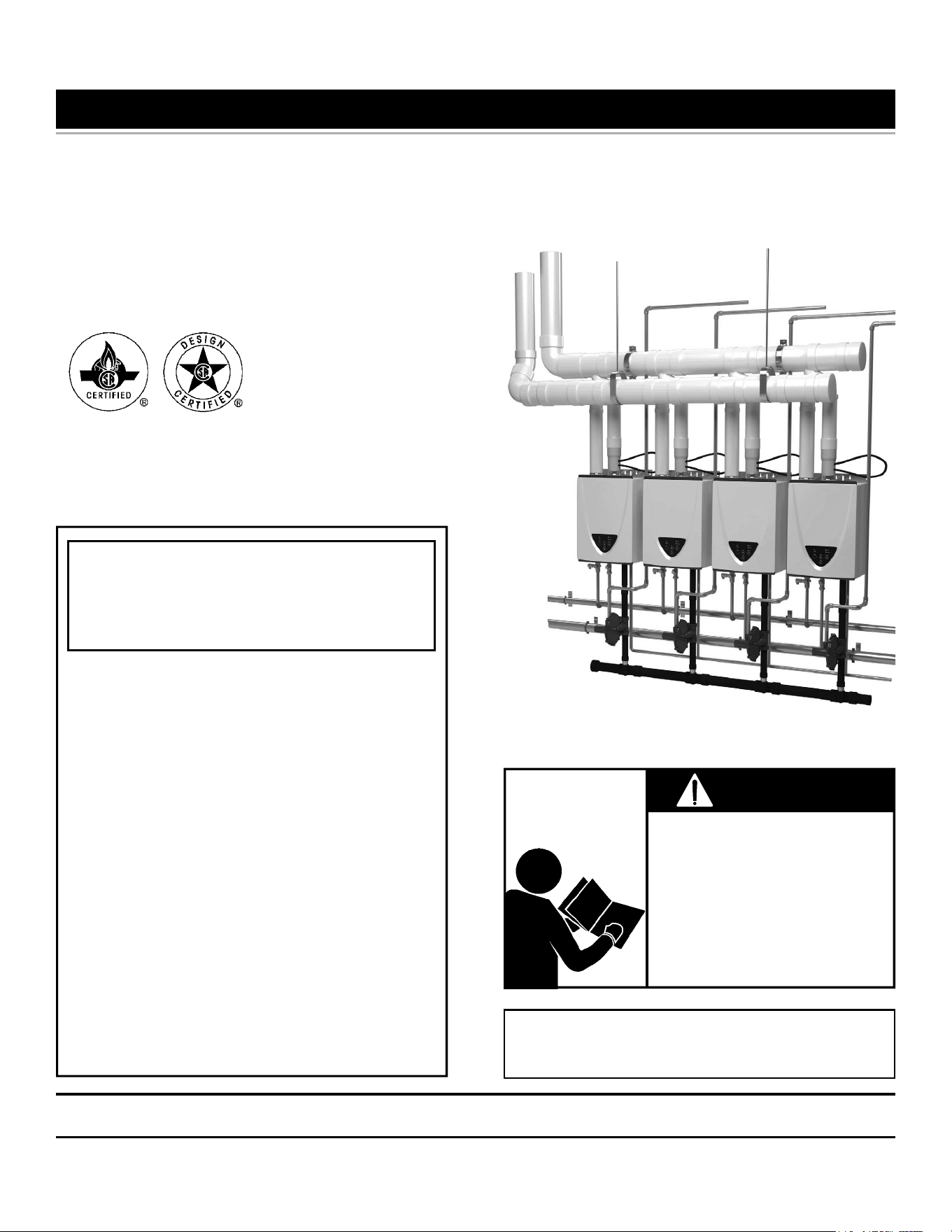
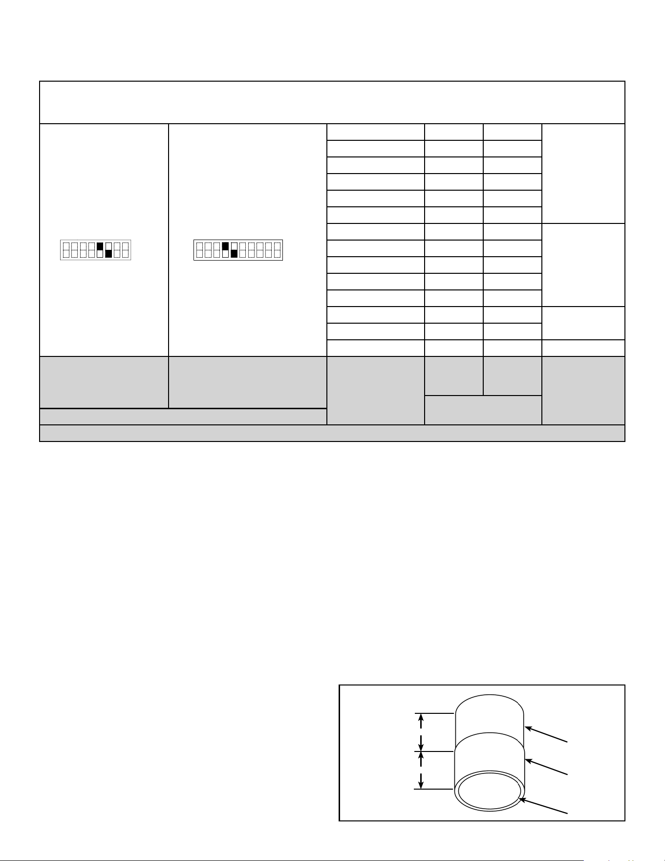
A PVC Adaptor, p/n 100113129 (Figure 2), is required when
using PVC piping for the exhaust. This PVC piping shall be
installed in the NRV outlet and transition to 4” Schedule 40
PVC piping.
WARNING! Use of cellular core PVC (ASTM F891), cellular
core CPVC, or Radel
®
(polyphenylsulfone) in non-metallic
venting systems is prohibited. Covering non-metallic vent
pipe and fittings with thermal insulation is prohibited.
Ø 4.375”
Ø 4.5”
Ø 4”
2”
2”
Figure 2. PVC Adaptor (p/n 100113129)
100271266 5
VENT & EXHAUST INSTALLATION
1. All vent piping must be supported by hangers. DO NOT
let the water heaters support the weight of the venting.
• horizontal vent piping must be supported every 3 ft.
(0.91m).
• vertical vent piping must be supported every 5 ft. (1.5m).
2. Horizontal vent runs require an upward slope of 1/4 in.
per foot (21mm per metre).
3. Each connection in the vent system must be air tight and
tested before putting the heaters into operation.
4. All common vented installations require a condensate
drain in the exhaust vent run.
5. The termination for side wall venting shall be a 45° elbow
for the exhaust, and a 90° elbow for the intake. Install
screens with minimum 3/4 in. (19mm) mesh spacing in
each termination to prevent foreign material from entering
the vent system.
6. The terminations for the roof and air intake lines shall
consist of one 90° elbow and one 45° elbow as shown in
Figure 4 through Figure 11. The terminations may use two
90° elbows. Install screens with minimum 3/4 in. (19mm)
mesh spacing in each termination to prevent foreign
material from entering the vent system.
7. Refer to the Installation Manual and Owner’s Guide for
further installation instructions.
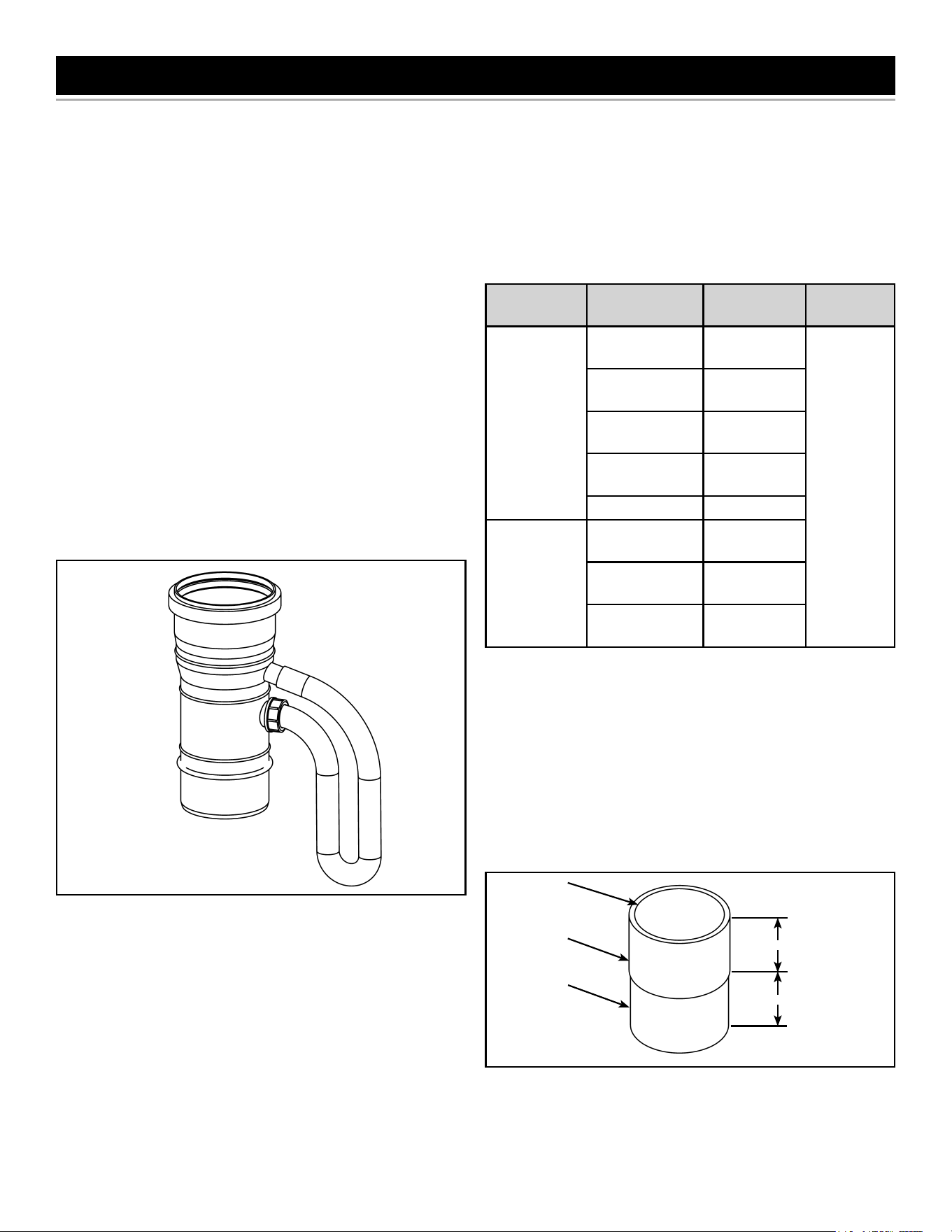
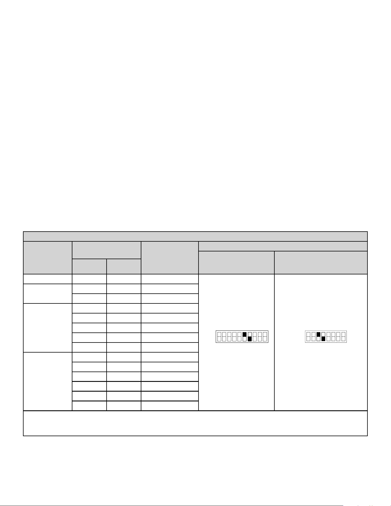
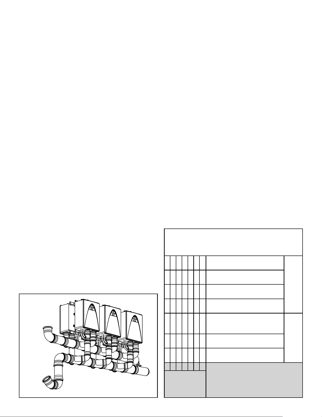
Common-venting system
Vent
Diameter* (D)
Max. No. of
water heaters
Max. equivalent
vent length** (L)
Intake and
Exhaust each
DIP switch settings
240 Indoor (T-H3J-DV)
340 Indoor (T-H3S-DV)
540 Indoor (T-H3-DV)
(Upper bank of DIPswitches)Horiz. Vert.
4 in. (110mm) 2 2 25 ft. (7.6 m)
OFF
ON
123456789 10
No.6: ON
No.7: OFF
OFF
ON
12345678
No.3: ON
No.4: OFF
5 in. (125mm)
2 2 50 ft. (15.2 m)
3 3 20 ft. (6.1 m)
6 in. (160mm)
2 2 100 ft. (30.5 m)
3 3 75 ft. (22.9 m)
4 N/A 50 ft. (15.2 m
5 N/A 25 ft. (7.6 m)
6 N/A 20 ft. (6.1 m)
8 in. (200mm)
3 3 100 ft. (30.5 m)
4 N/A 100 ft. (30.5 m)
5 N/A 85 ft. (25.9 m)
6 N/A 65 ft. (19.8 m)
7 N/A 50 ft. (15.2 m)
8 N/A 41 ft. (12.5 m)
*Diameters of pipes are in accordance with Centrotherm’s specifications.
**One elbow is equivalent to 5 ft (1.5 m) linear length. The maximum number of elbows allowed is 5. See calculations
on page 8.
Figure 3. Vent Length Dimensioning
CONDENSATE
This water heater is a high efficiency condensing water heater
that produces condensate (acidic water). The venting must
be installed such that the condensate will not drain through
a heater. The contractor must install a condensate trap and
pitch the exhaust venting towards the trap so it can be drained.
6 100271266
COMMON VENT TYPES
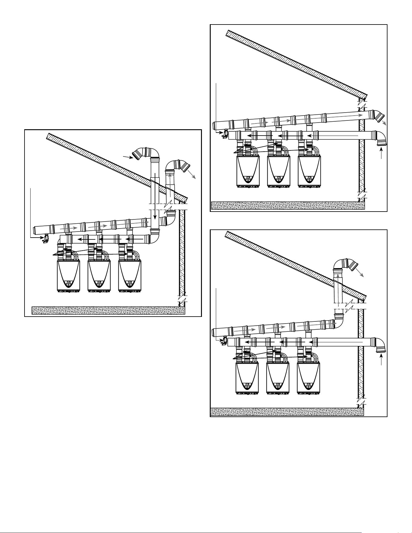
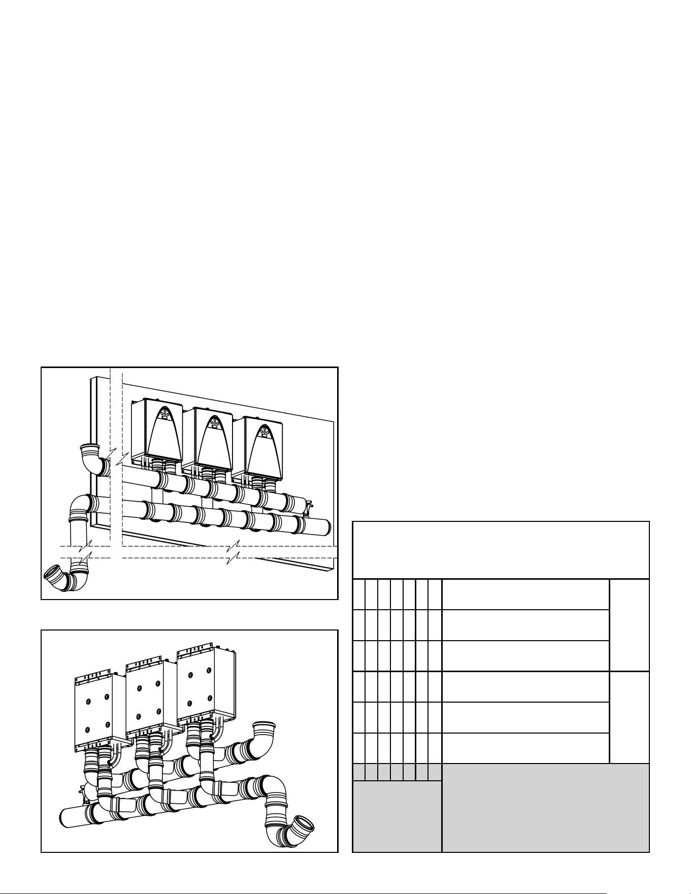
Horizontal (Side-By-Side)
A maximum of 8 condensing heaters may be common vented
horizontally, in either an in-line or back-to-back configuration.
The use of reducing wyes to join each heater’s venting to the
trunk line is preferred, however reducing tees are acceptable.
The maximum length of the single exhaust vent line from the
heater to the common vent header (trunk line) is 10 ft. (3 m),
with only two elbows allowed. This vent size should be of
4 in. piping.
The exhaust piping should be sloped back to the heater 1/4 in.
per foot (21mm per metre) or as per local code requirements.
Intake
Wall
Exhaust
Roof
Condensate drain port
Non-Return
Valve
Figure 4. Typical Common-Vent Through The Roof
Installation
Intake
Wall
Exhaust
Roof
Condensate drain port
Non-Return
Valve
Figure 5. Typical Common-Vent Through The Wall
Installation
Intake
Wall
Exhaust
Roof
Condensate drain port
Non-Return
Valve
Figure 6. Typical Common-Vent Combination Wall /
Roof Installation
100271266 7
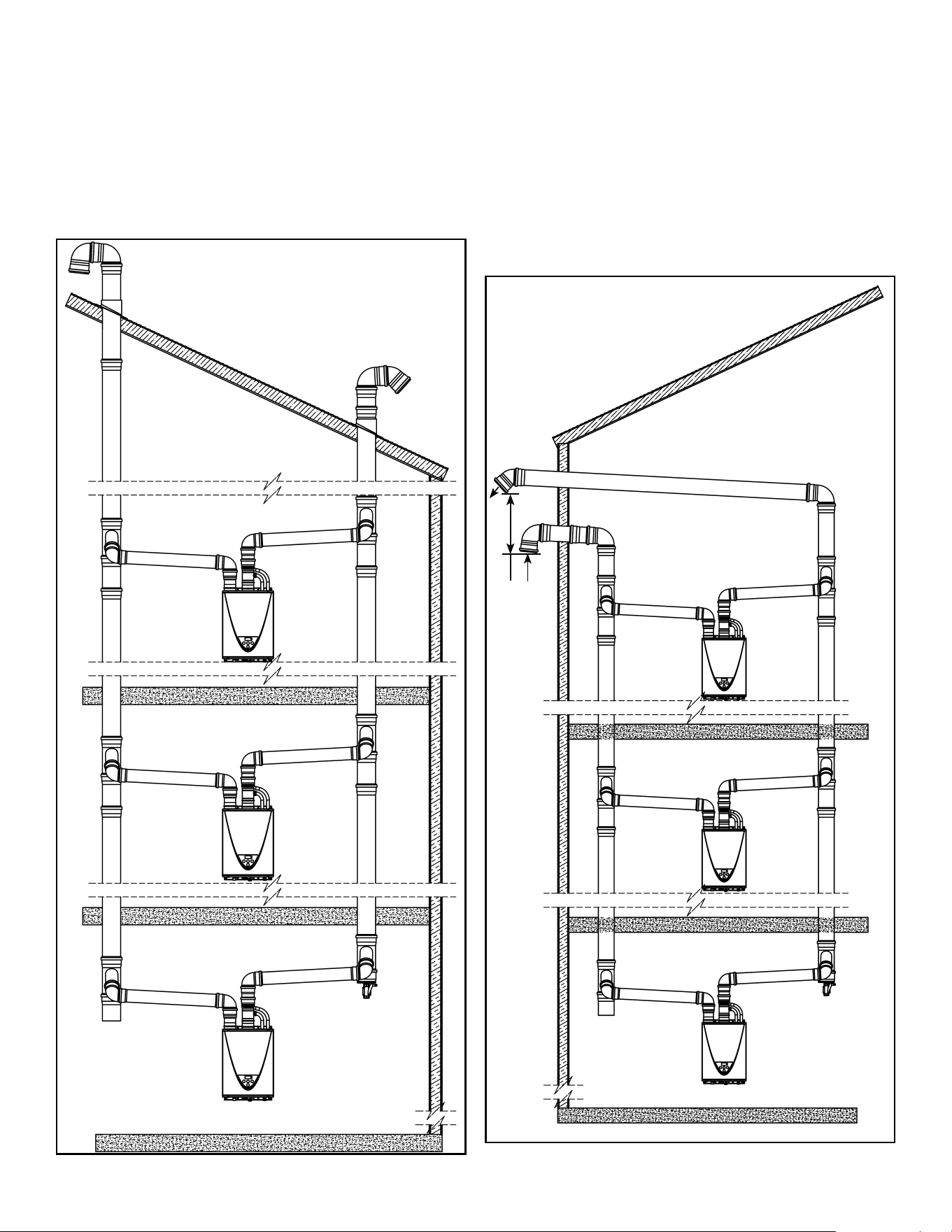
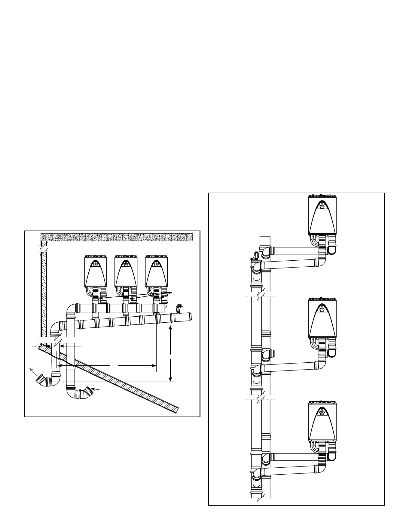
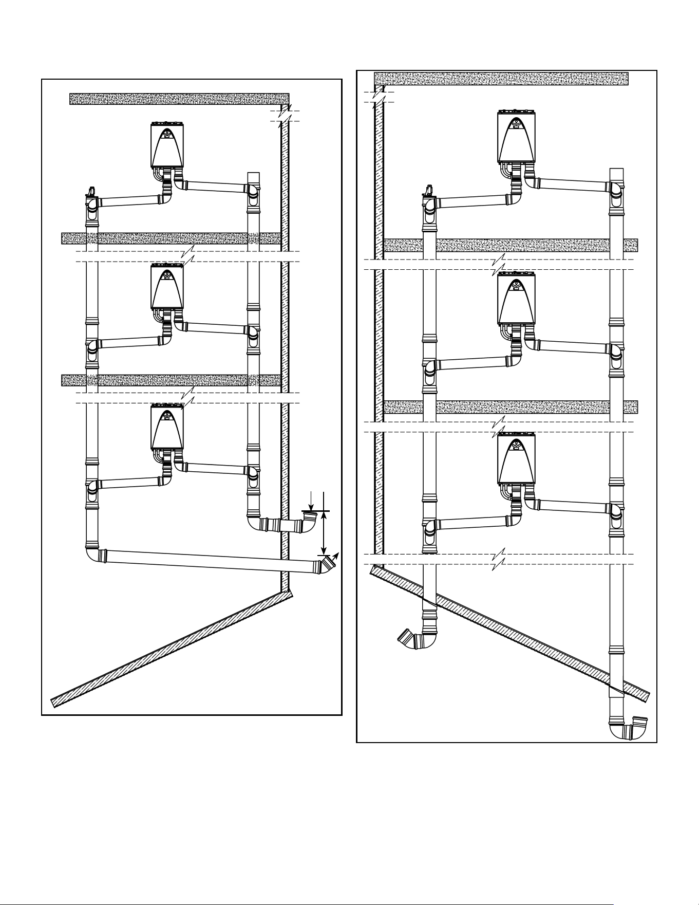
Vertical (Multi-Level)
Condensing heaters may also be installed in a multi-level,
vertical configuration. A maximum of 3 heaters may be
common vented in a vertical configuration. The use of reducing
wyes to join each heater’s venting to the trunk line is preferred,
however reducing tees are acceptable. The maximum vertical
distance of the single exhaust vent line from the heater to
the common vent header (trunk line) is 10 ft. (3m), with only
two elbows allowed. This vent size should be of 4 in. piping.
Figure 7. Vertical Through-The-Roof Venting
Intake
Exhaust
3’ MIN
Figure 8. Vertical Through-The-Wall Venting
8 100271266
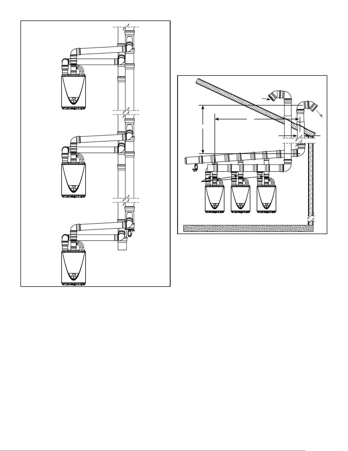
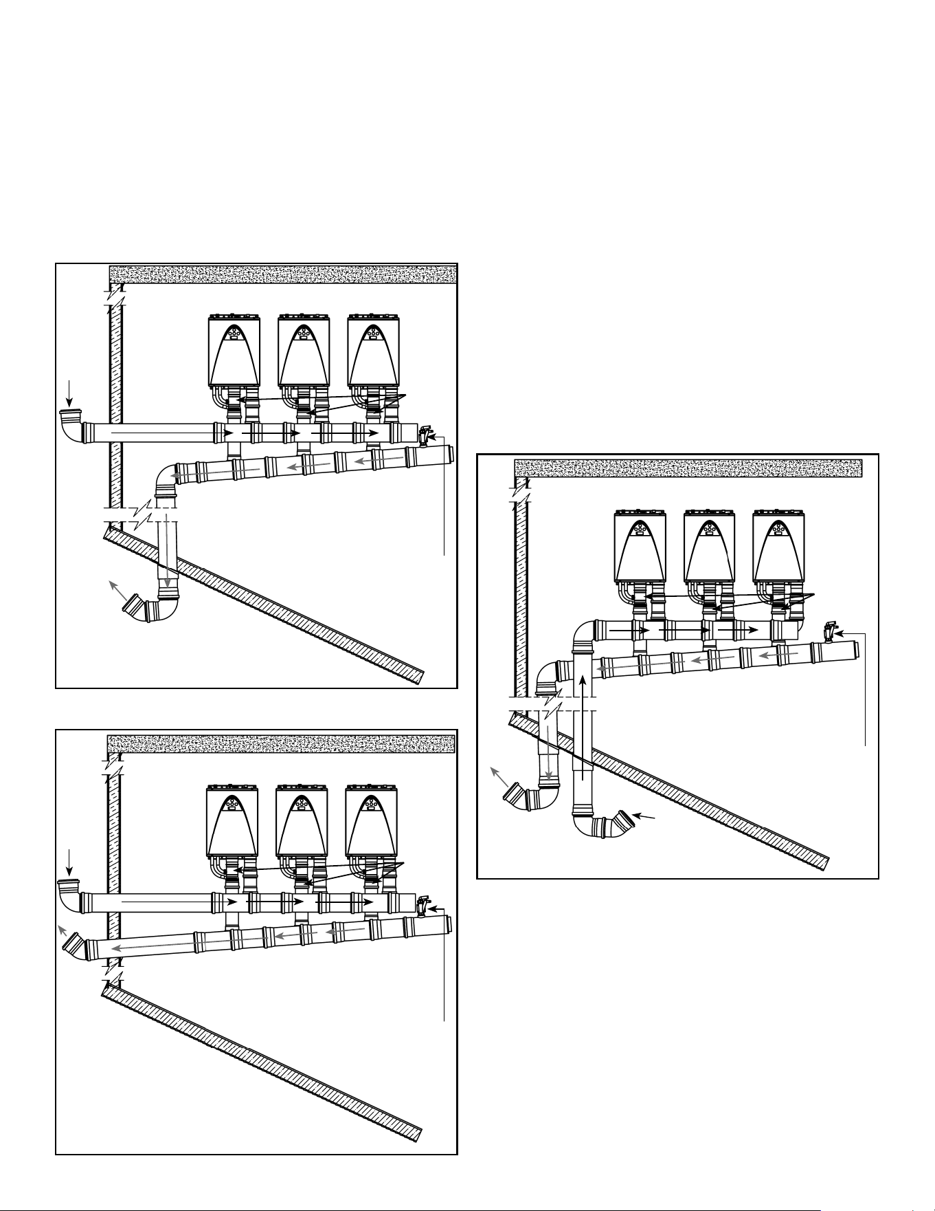
Figure 9. Vertical Venting In A Single Chase
DETERMINING THE COMMON VENT DIAMETER
Horizontal Configuration
In order to determine the vent trunk diameter (D), the total
equivalent vent length and number of heaters must first be
determined. The total equivalent vent length (L) is calculated
by adding the horizontal length (W) and the vertical length (H),
with each 90° elbow equaling 5 ft. (1.5m) of pipe.
Intake
Exhaust
Non-Return
Valve
"H"
"W"
"D"
Figure 10. Vent Dimensioning
Notes:
• Total vent length (L) = H + W + (Number of Elbows x 5)
• Vent diameter=”D”
• For the clearances between the exhaust termination and
the intake termination refer to the heater Installation and
Owner’s Guide.
• Once you have determined L, see Figure 3 to determine
the common vent header size. The common vent header is
dependent on the number of heaters connected to the vent.
For example, if you have 4 heaters vented together with L
= 60 ft. (18m) your minimum common vent diameter is 8 in.
• The air intake sizing follows this same criteria.
• Install screens in each termination to prevent foreign
material from entering the vent system. The mesh spacing
of the screen should be no less than 3/4 in. (19mm).
100271266 9
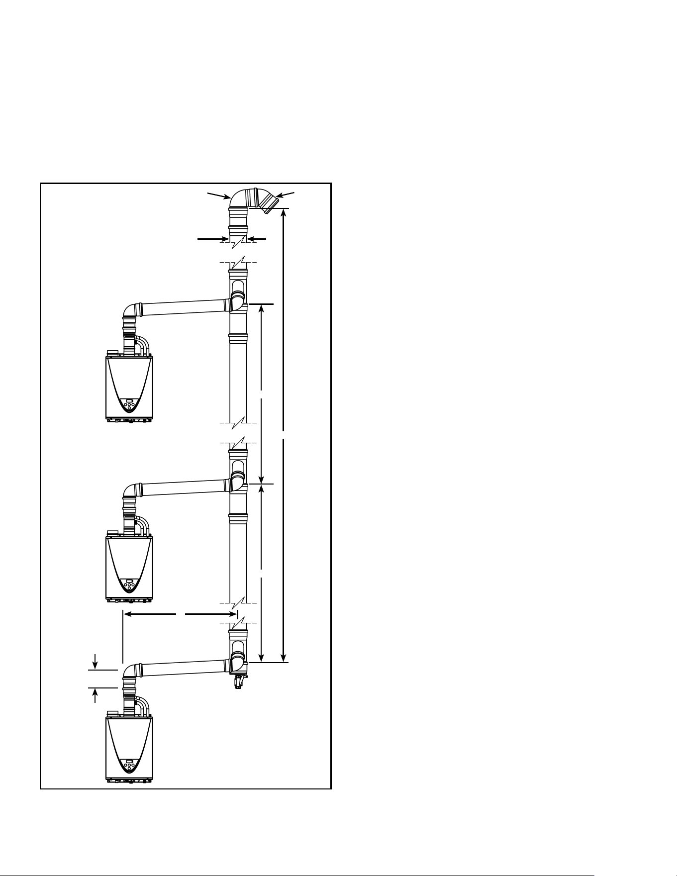
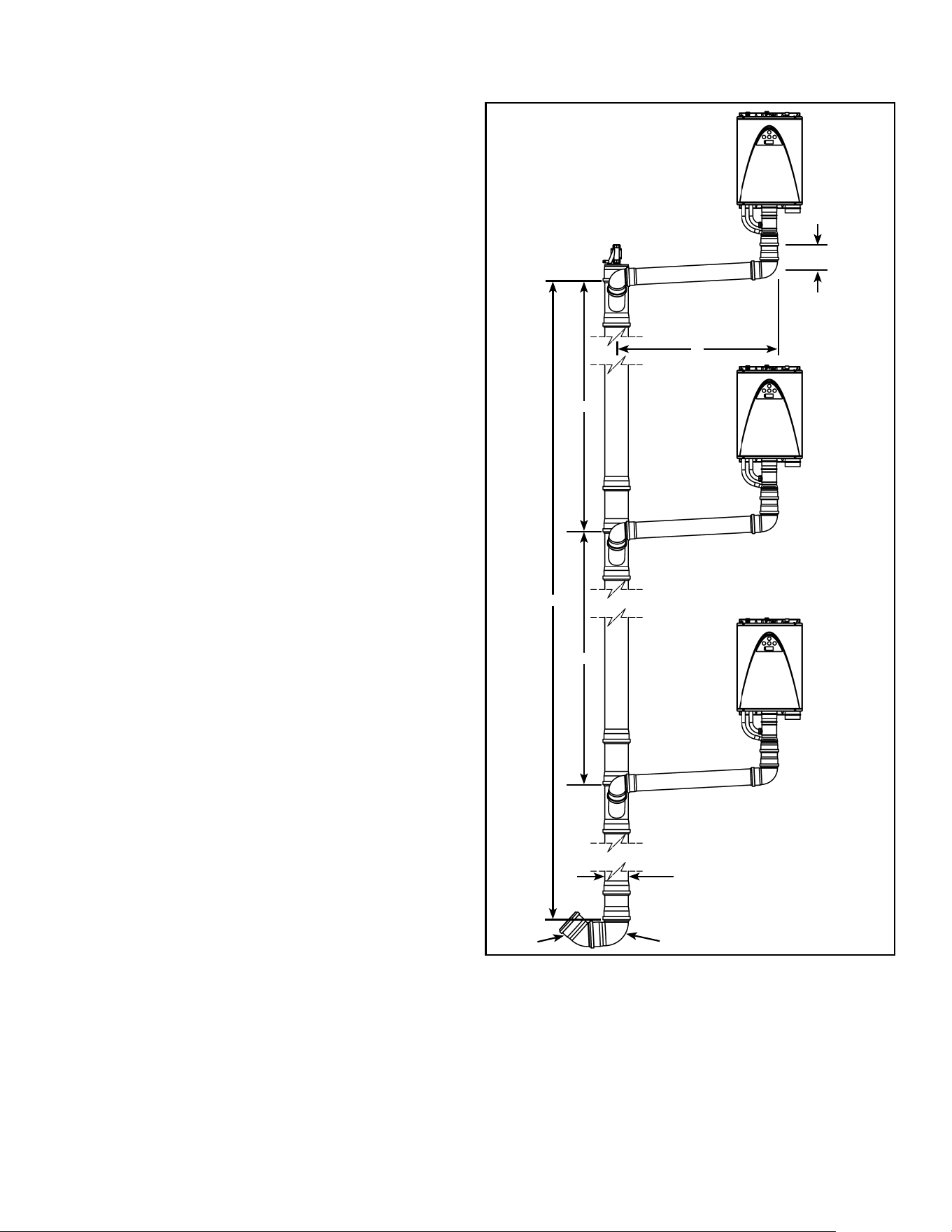
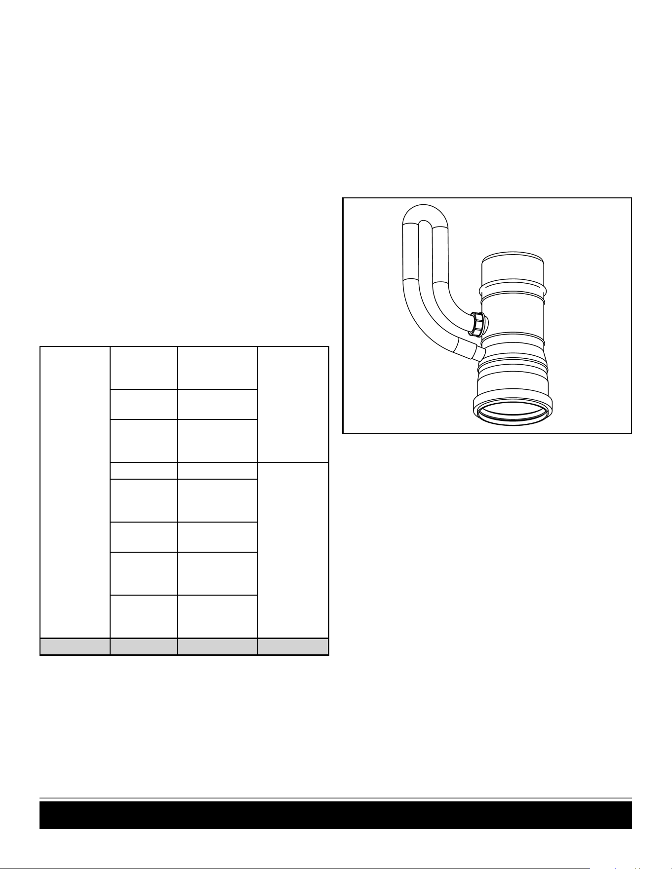
Vertical Configuration
Maximum number of 3 heaters may be common vented in a
vertical configuration. The maximum equivalent length of the
common vent chimney is 100 ft. (30m) using 8 in. pipe and
the trunk line should be a constant size.
Restrictions for vertical common venting (intake and exhaust)
are as follows (see Figure 11):
• L
1
+ L
2
≤ 10 ft. + 2 elbows, max.
• Total vent length = L
1
+ L
2
+ H
t
H
1
H
2
H
t
L
2
L
1
90° 45°
“T”
Note: Air intake system not shown
but has the same sizing criteria as
the exhaust system and it must be
installed. Exhaust only installations
are NOT allowed.
Figure 11. Vent Dimensioning
CLEARANCES
NOTICE: Follow all local and national codes in regards to
proper termination clearances. In the absence of such codes,
the clearances below can be used as guidelines. Local codes
supersede these guidelines.
Sidewall Terminations
For multiple sidewall exhaust terminations, an exhaust
termination must be at least 1 ft. (305mm) away from another
exhaust termination. An exhaust termination must also be at
least 2 ft. (610mm) away from an inside corner. (If the adjacent
wall is less than 2 ft. (610mm) of length, the minimum required
distance away from the inside corner will be equal to the length
of that adjacent wall.)
For direct-vent sidewall terminations that use two separate
penetrations for the intake and exhaust, maintain the
termination clearances shown in the diagrams in the
Installation Manual and Owner’s Guide.
Exhaust and/or direct-vent sidewall terminations should be
at least 2 ft. (610mm) away from an opposite surface/wall.
Do not place the termination directly in front of an opening
into a building.
Rooftop Terminations
Exhaust terminations must be at least 1 ft. (305mm) away
from any obstructions.
1. Clearances for multiple exhausts and intakes – sidewall
& roof: maintain the termination clearances shown in the
diagrams in the Installation Manual and Owner’s Guide.
10 100271266
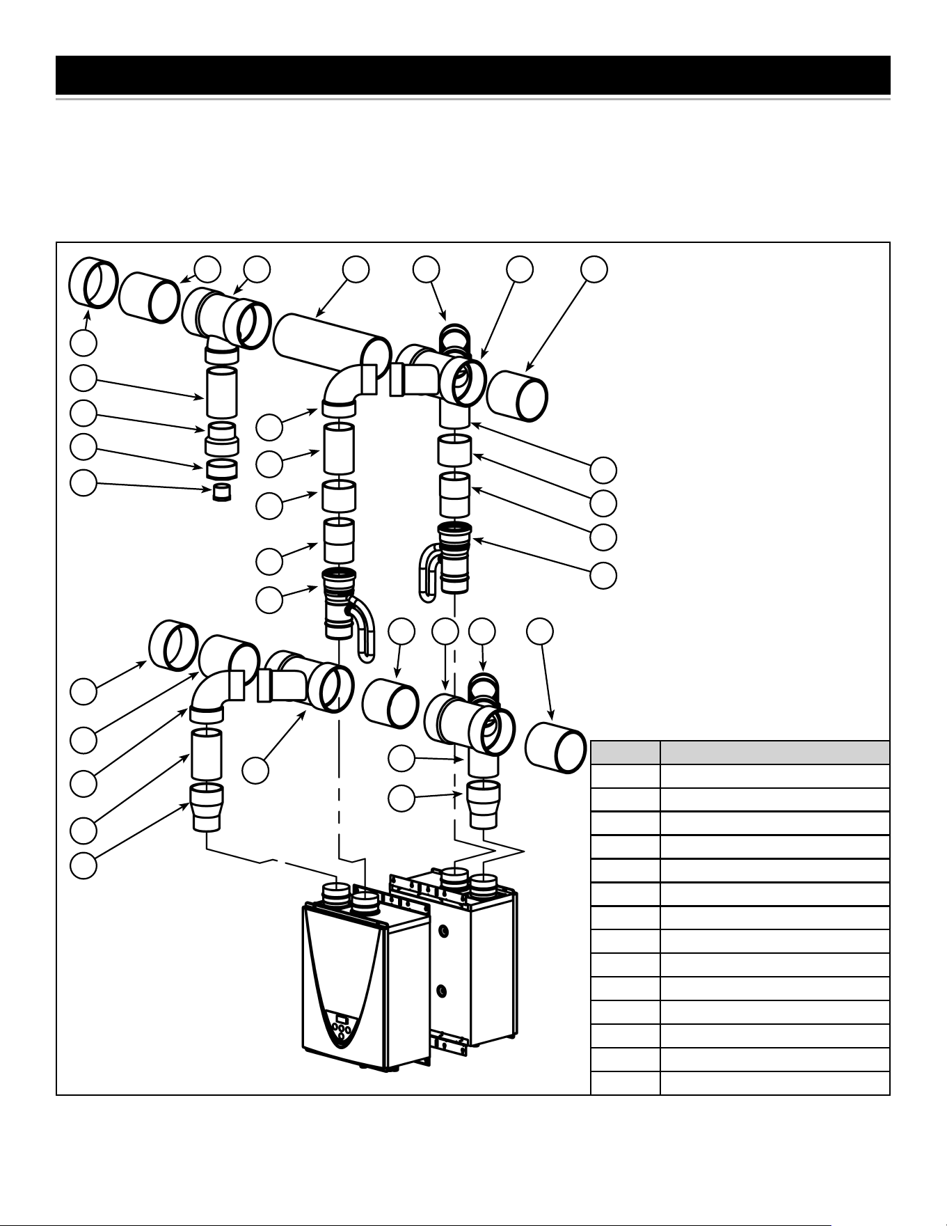
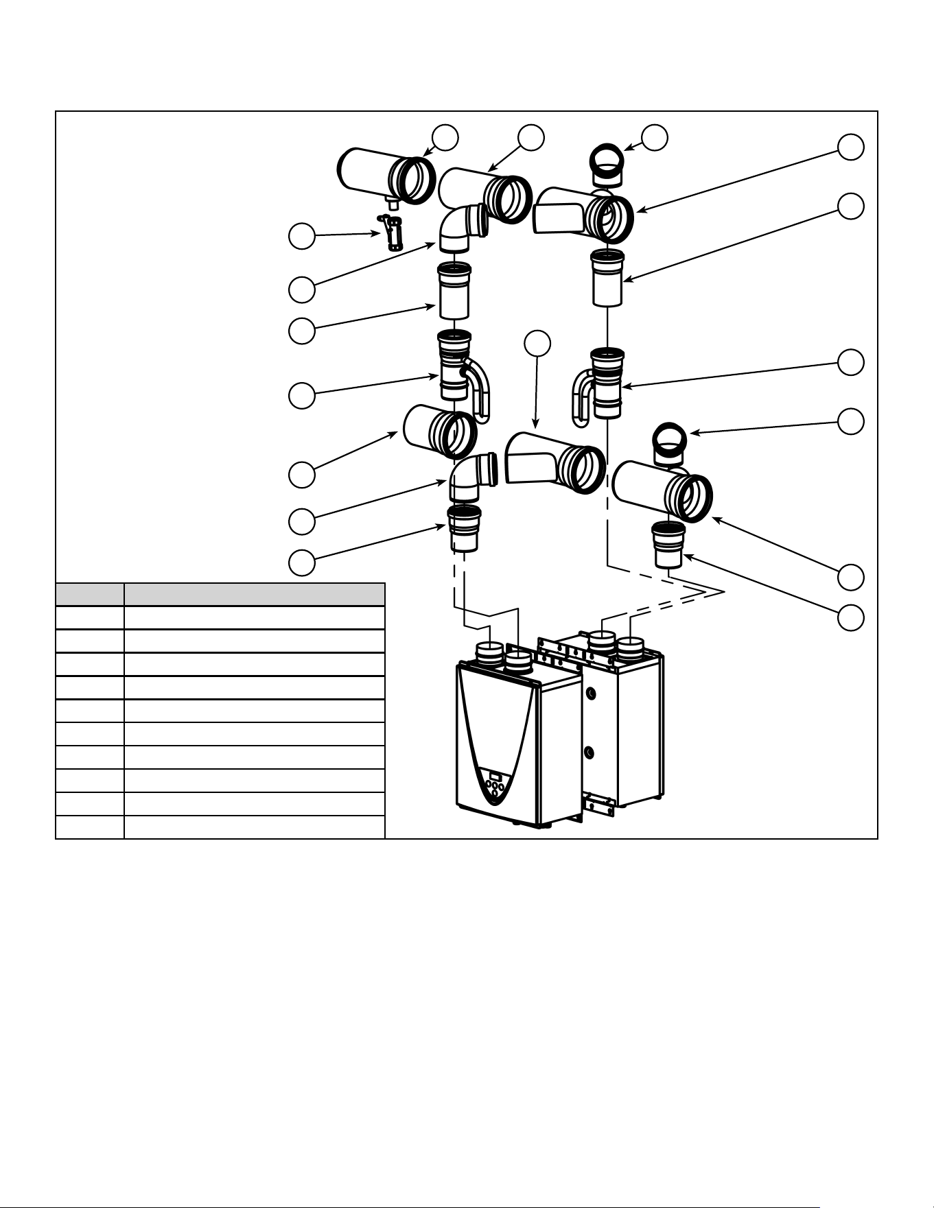
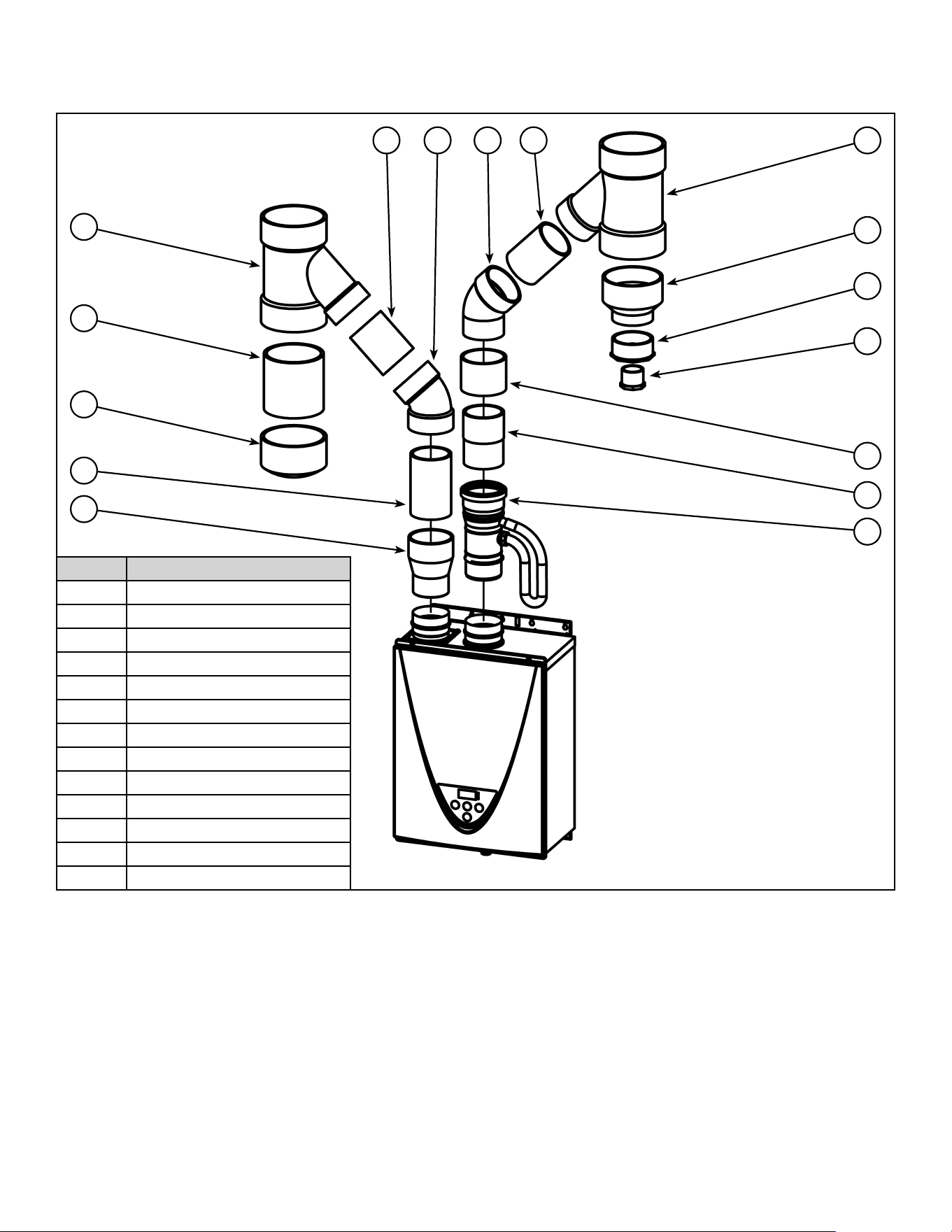
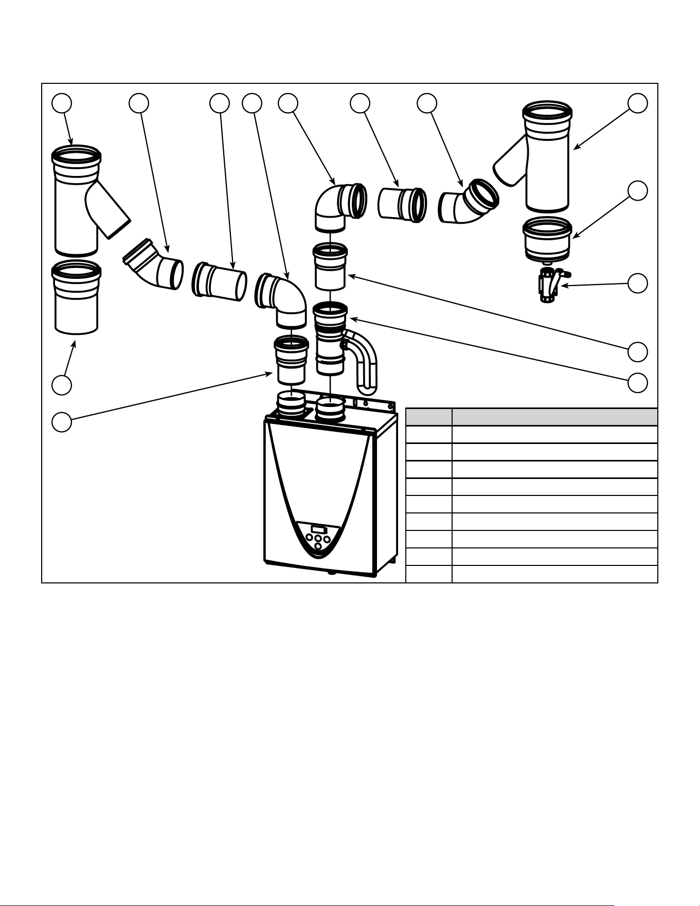
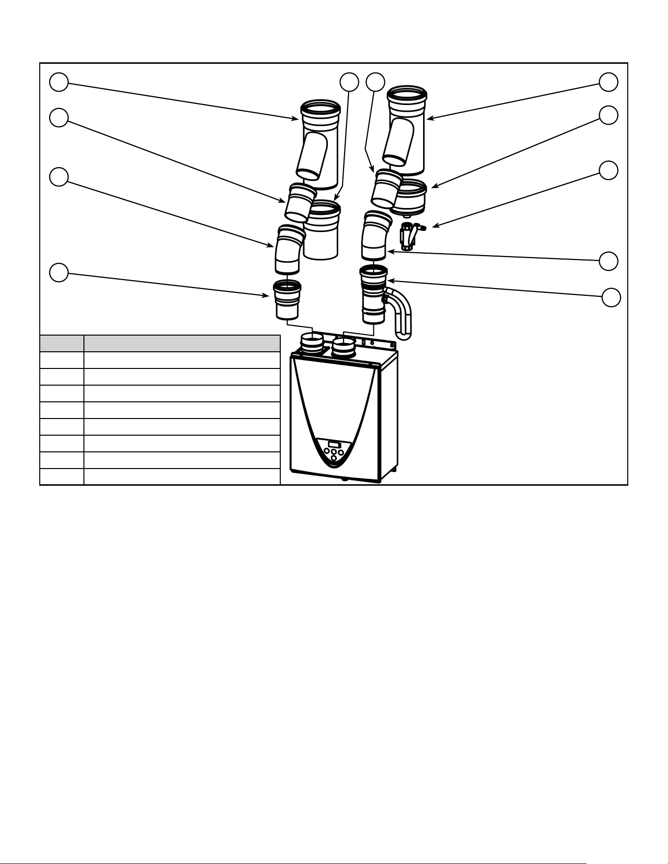
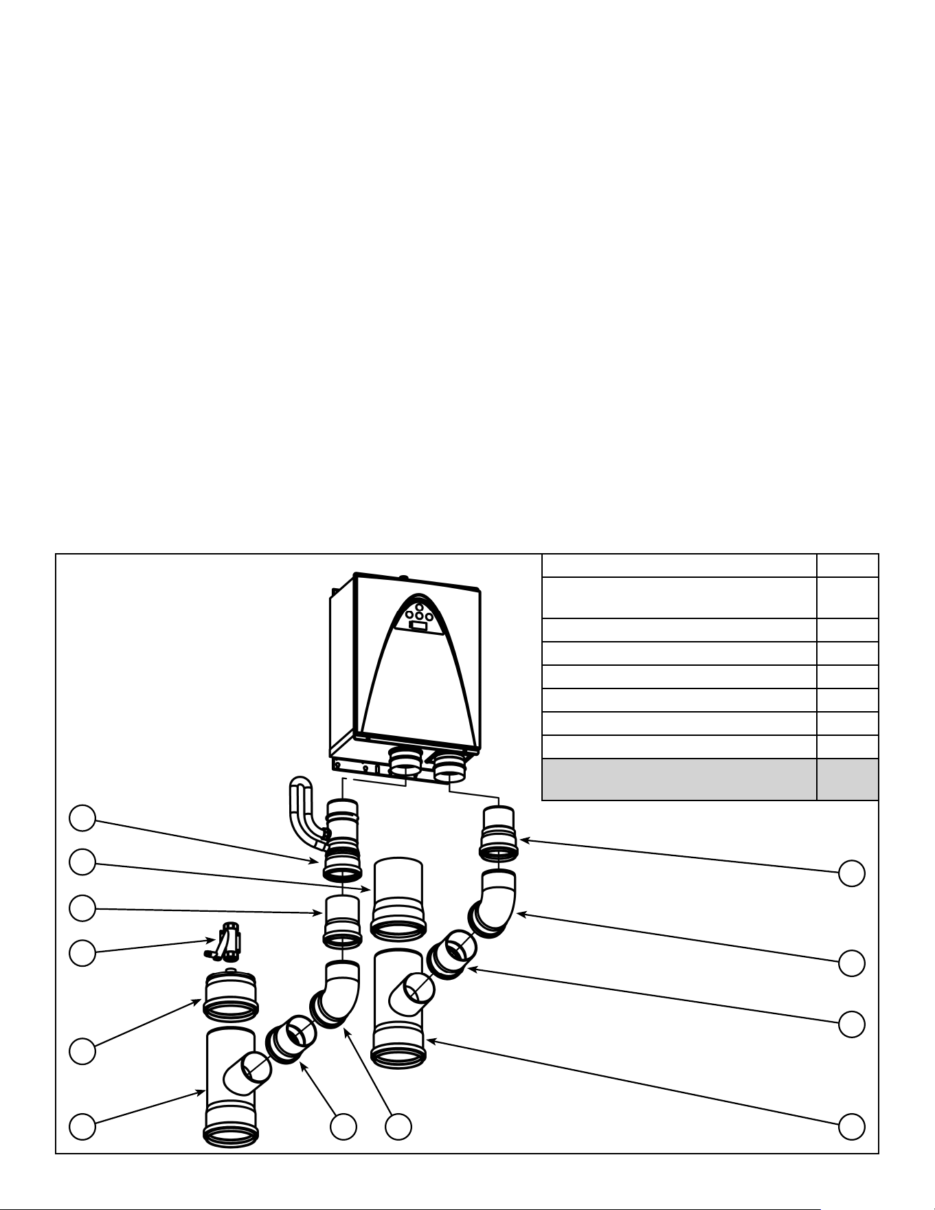
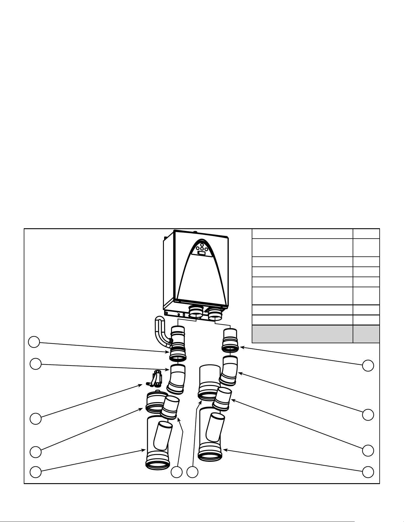
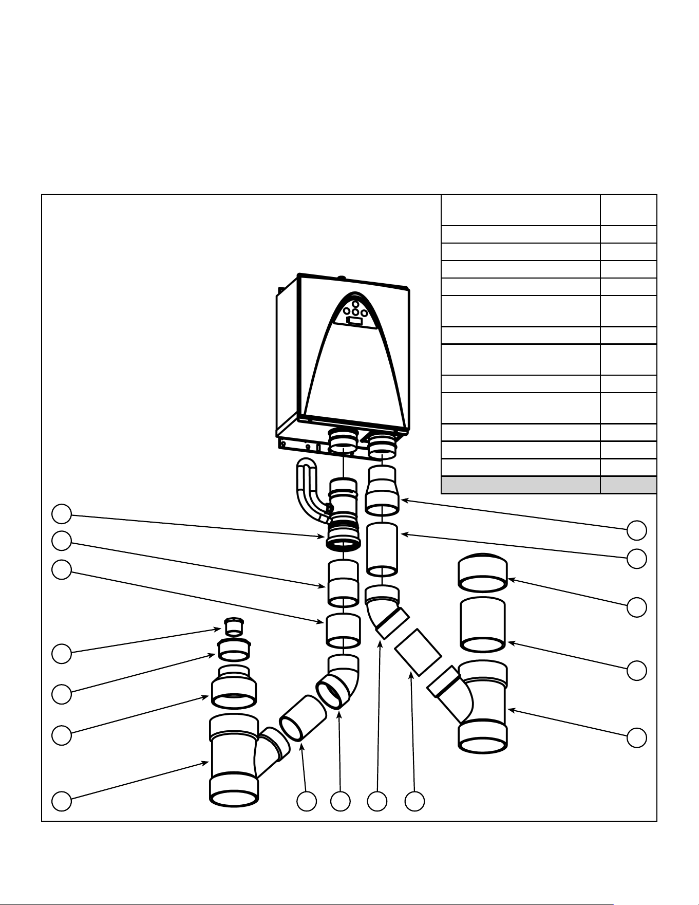
VENTING COMPONENTS
The following pages show exploded vent fitting diagrams for each configuration (horizontal or vertical) for PVC and
polypropylene piping. Each configuration will have a table showing the number of fittings needed corresponding to the
number of heaters being common vented.
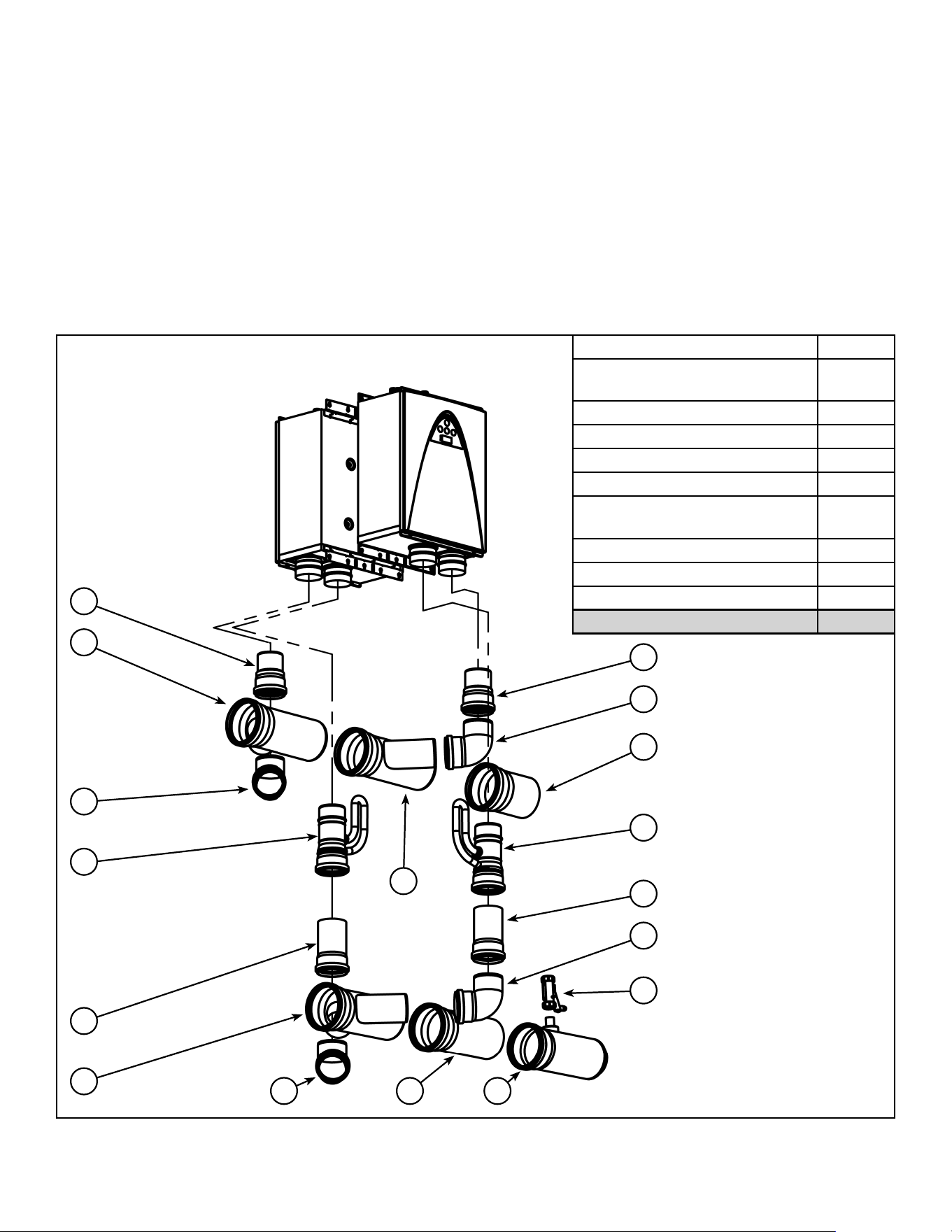
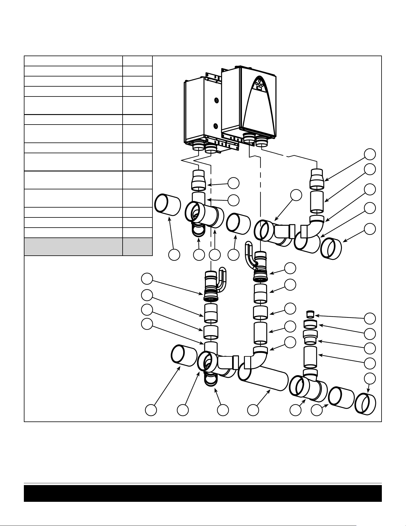
HORIZONTAL CONFIGURATIONS - (SCHEDULE 40 PVC PIPING)
Back-To-Back
24
22
17
16
15
15
21
22
14
20
16
17 221922
1718
20
16
17
18
21
14
22
25
16
16
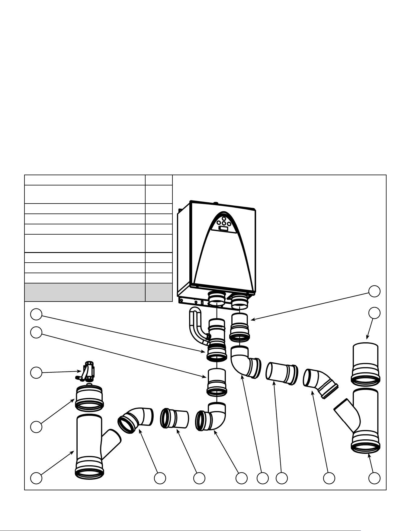
Item # Venting Component
14 Non-Return Valve (NRV)
15 4” to 3” Reducer (PVC)
16 4” Vent Pipe (PVC)
17 4” x 90° Street Elbow (PVC)
18 “D” x 4” Reducing Wye (PVC)
19 “D” x 4” Double Wye (PVC)
20 4” Coupling (PVC)
21 Polypropylene to PVC adaptor
22 “D” Vent Pipe (PVC)
23 2.5” x .75” NPT Adaptor (PVC)
24 4.5” x 2.5” Adaptor (PVC)
25 4” x 5” Reducer (PVC)
26 “D” Endcap (PVC)
29 “D” x 4” Reducing Tee (PVC)
26
2922
23
26
Figure 12. Venting Components Horizontal Configuration (Back-to-Back)
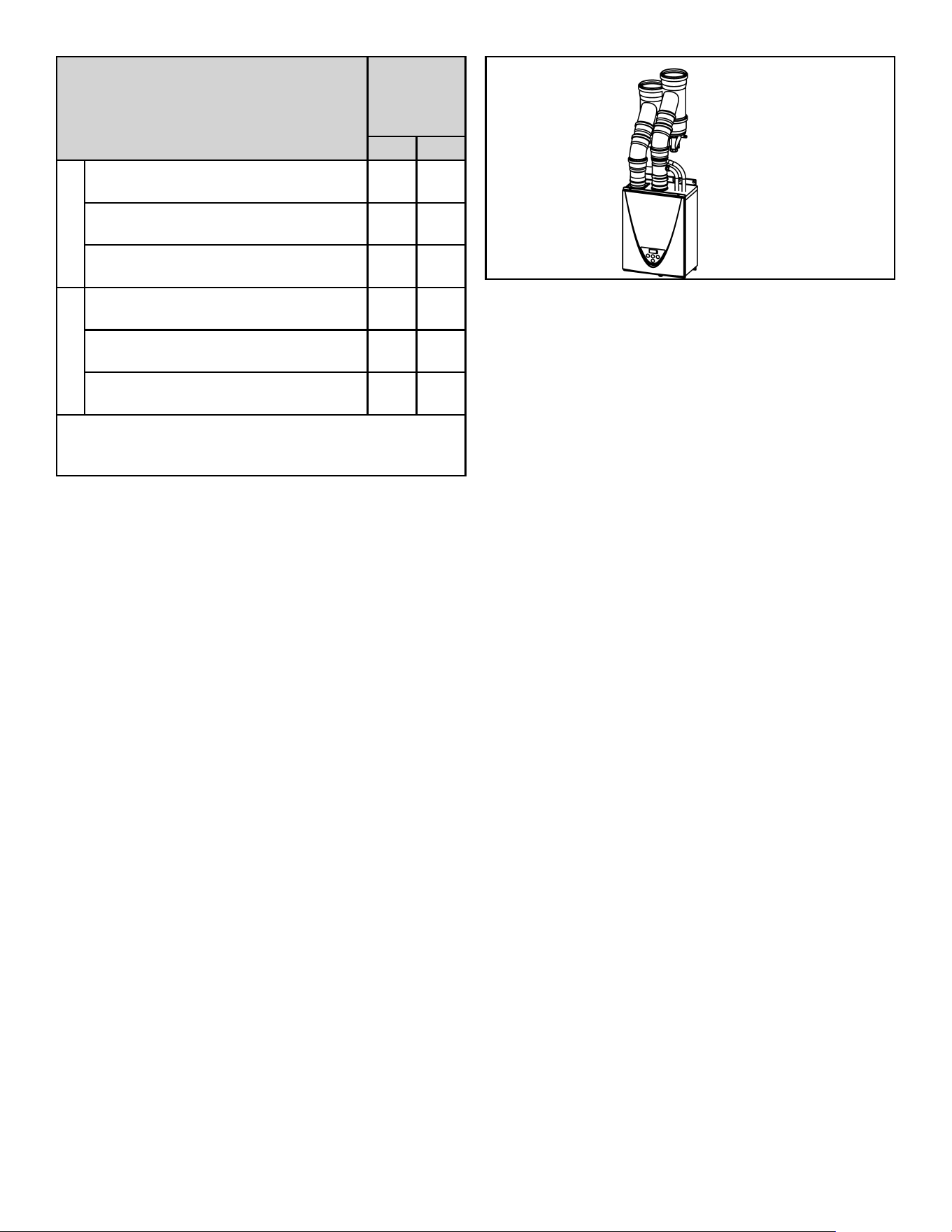
100271266 11
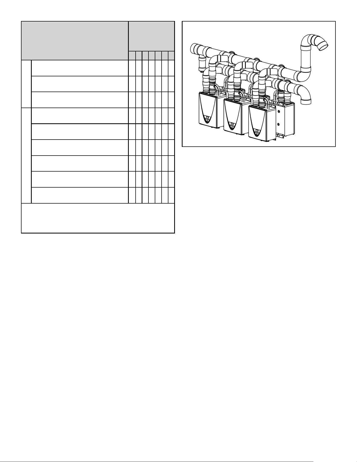
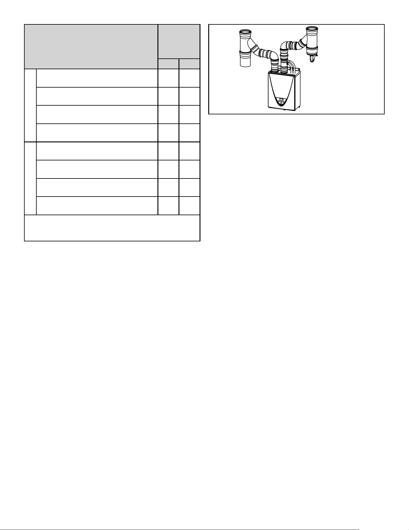
Venting Component
Number of
Back-to-Back
Common
Vented Heaters
2345678
Air Intake
4” to 3” Reducer (PVC)
(Item #15)
2345678
4” x 90° Street Elbow (PVC)
(Item #17)
2345678
“D” x 4” Reducing Wye (PVC)
(Item #18)
2345678
Exhaust
Non-Return Valve (NRV)
(Item #14)
2345678
4” x 90° Street Elbow (PVC)
(Item #17)
2345678
“D” x 4” Reducing Wye (PVC)
(Item #18)
0101010
“D” x 4” Double Wye (PVC)
(Item #19)
1122334
4” Coupling (PVC)
(Item #20)
2345678
Polypropylene to PVC adaptor
(Item #21)
2345678
* All PVC fittings and pipe shall be schedule 40.
“D” = Main Trunk Diameter.
Contractor to obtain proper pipe hangers for the venting
and air intake.
Table 2. List of Venting Components Horizontal
Configuration (Back-to-Back)
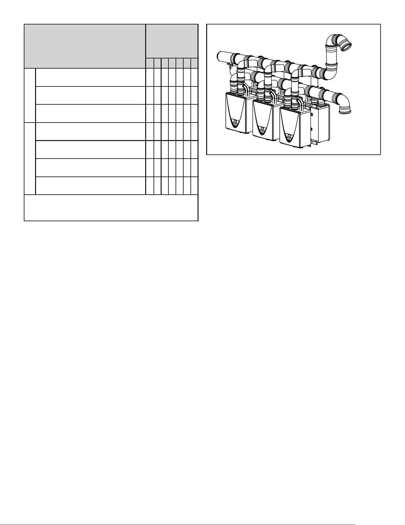
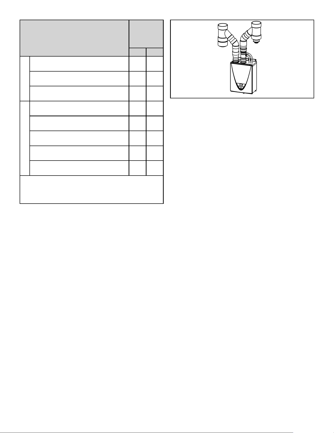
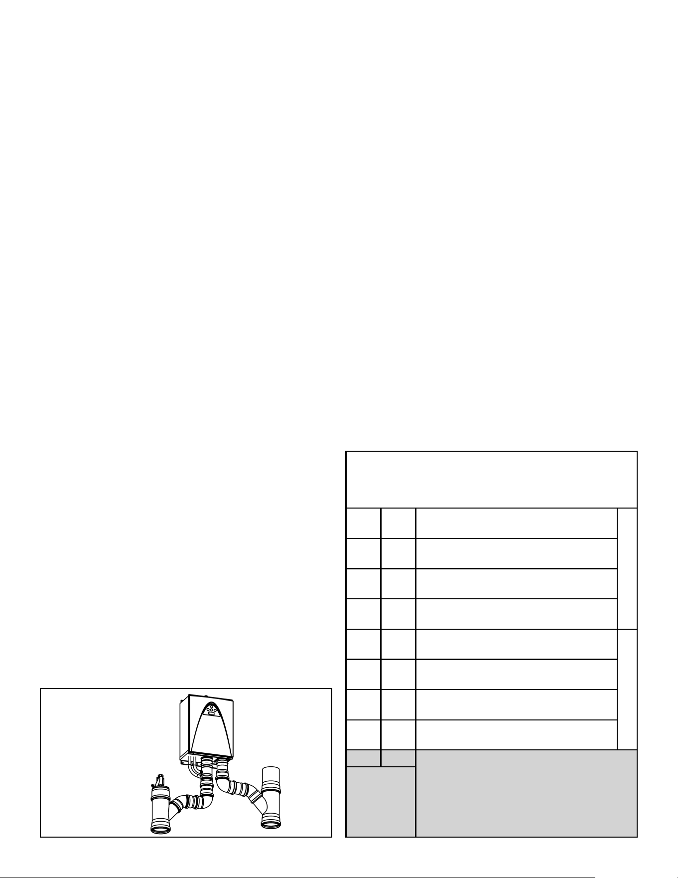
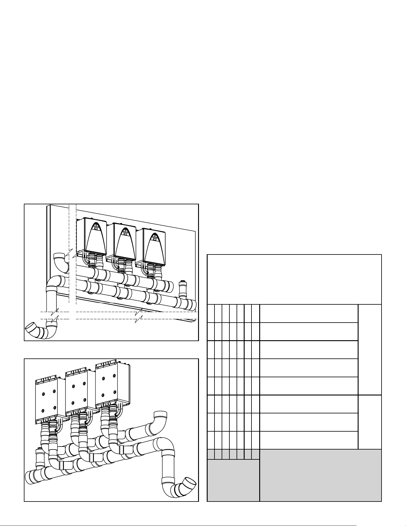
Figure 13. Horizontal Configuration (Back-to-Back)
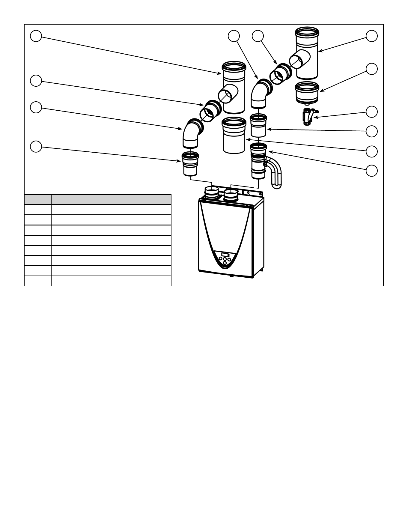
12 100271266
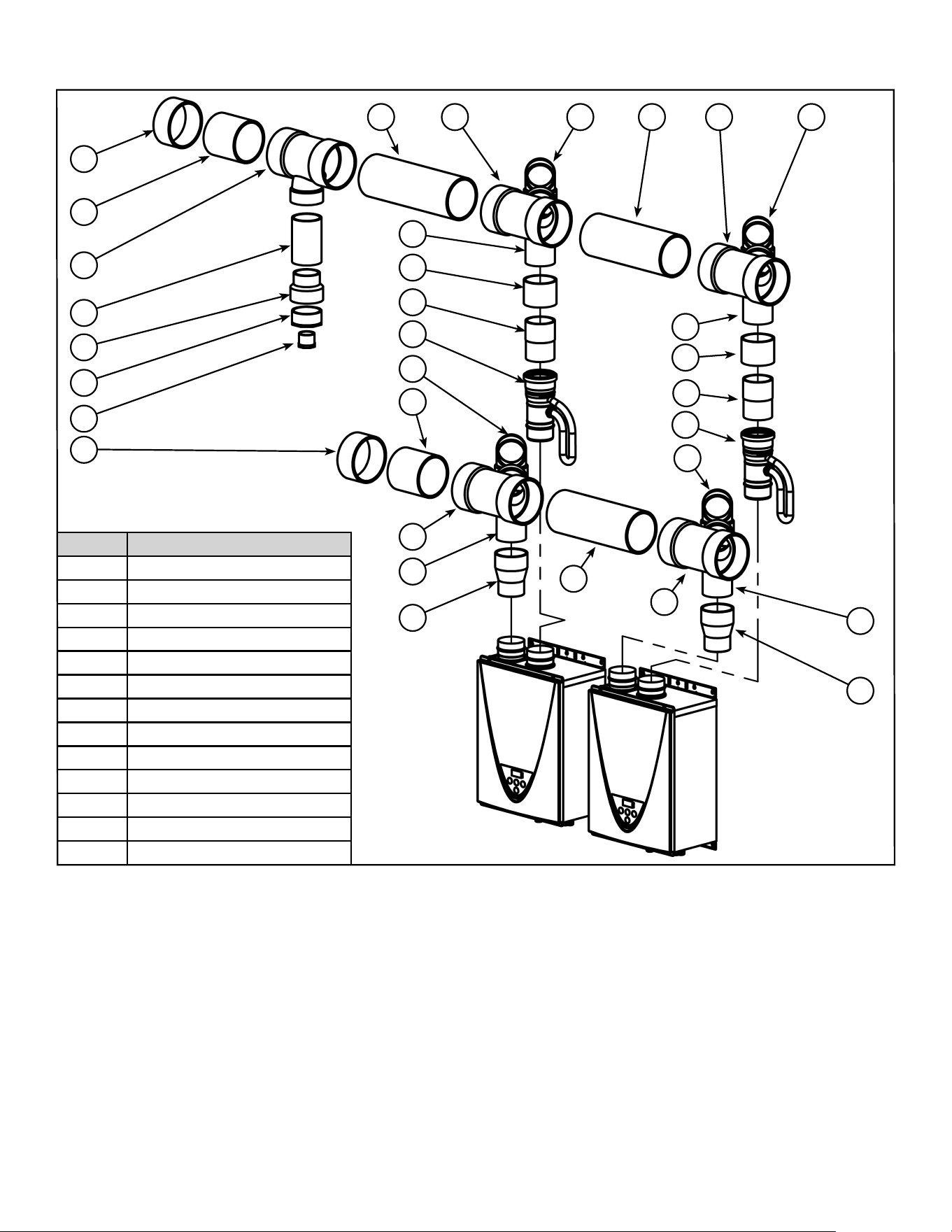
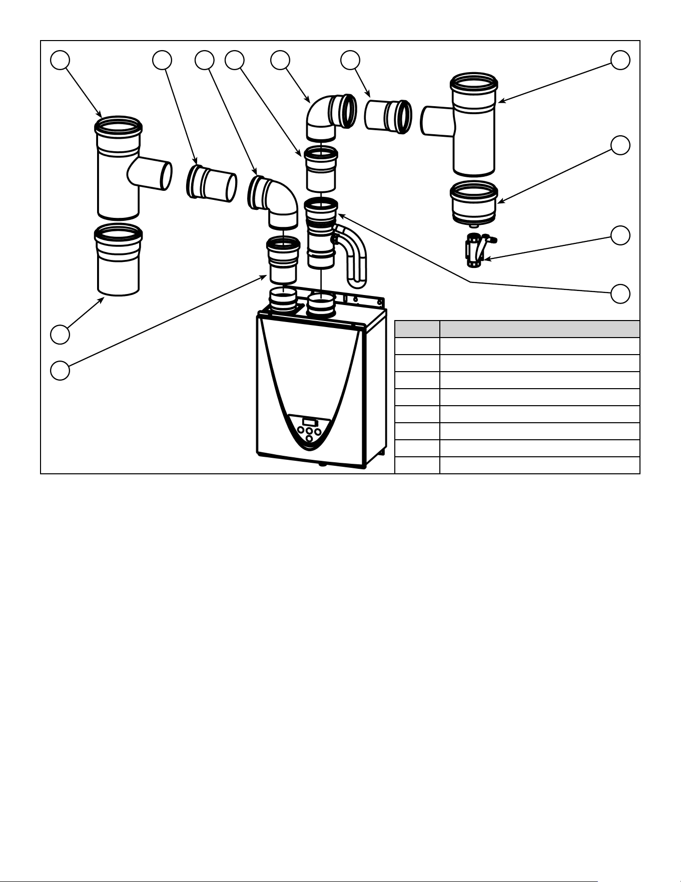
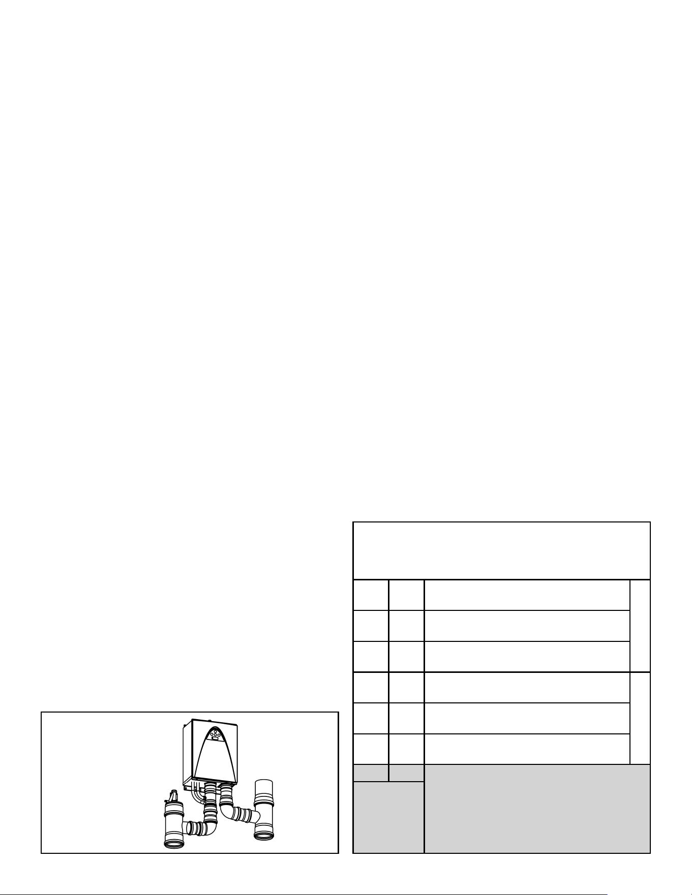
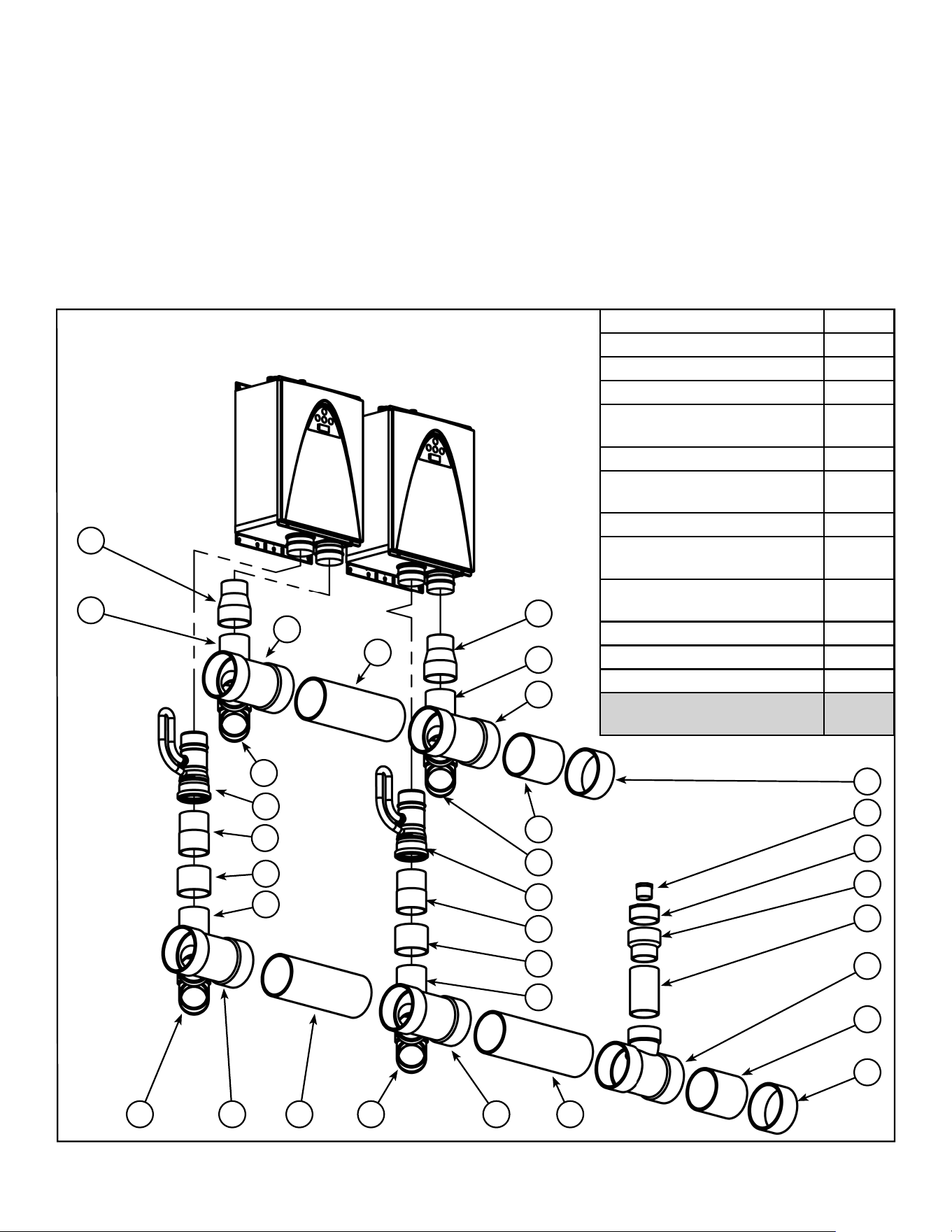
In-Line
22
16
16
14
21
20
1822
17
16
22
29
18
15
17
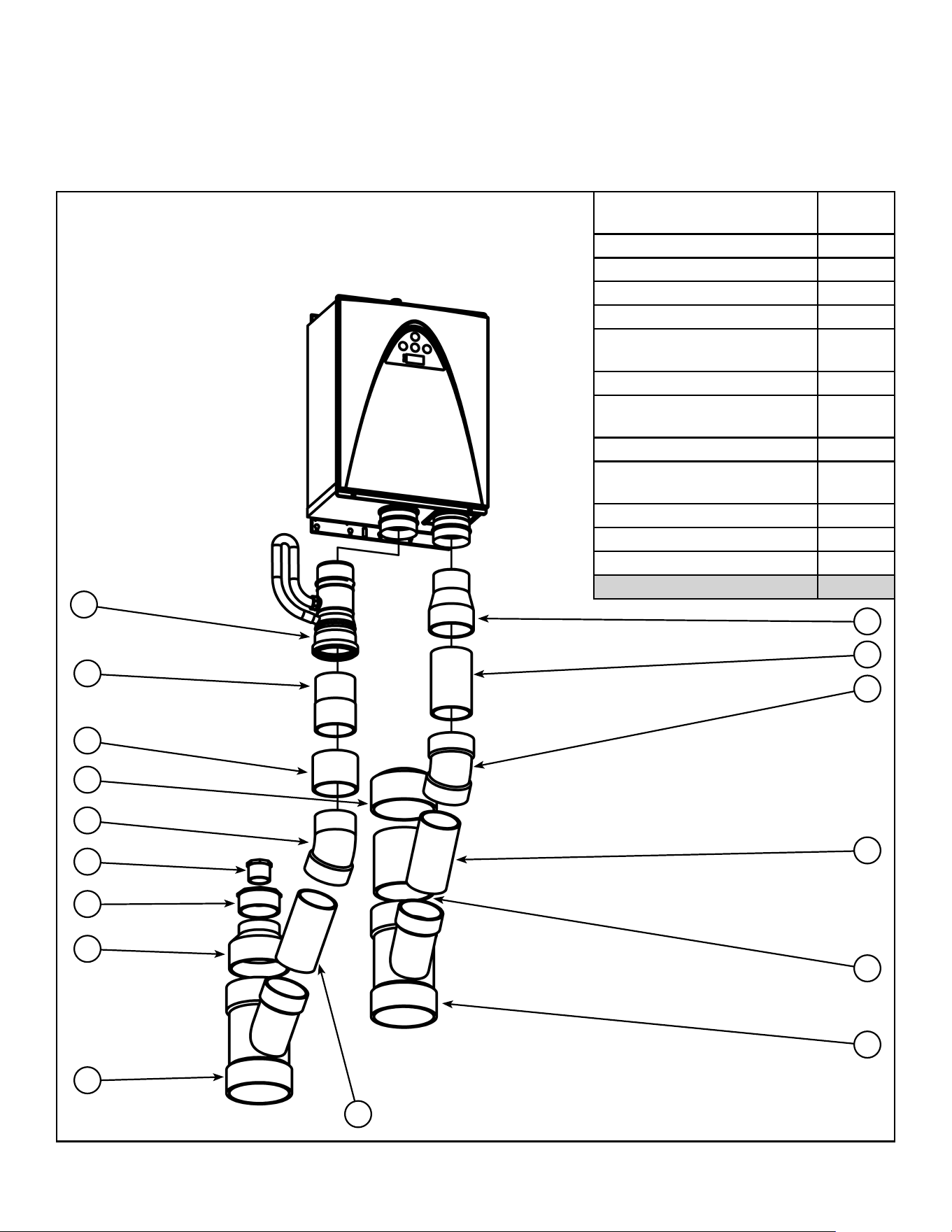
Item # Venting Component
14 Non-Return Valve (NRV)
15 4” to 3” Reducer (PVC)
16 4” Vent Pipe (PVC)
17 4” x 90° Street Elbow (PVC)
18 “D” x 4” Reducing Wye (PVC)
20 4” Coupling (PVC)
21 Polypropylene to PVC adaptor
22 “D” Vent Pipe (PVC)
23 2.5” x .75” NPT Adaptor (PVC)
24 4.5” x 2.5” Adaptor (PVC)
25 4” x 5” Reducer (PVC)
26 “D” Endcap (PVC)
29 “D” x 4” Reducing Tee (PVC)
22 18 17
16
20
21
14
17
22
18
16
15
26
25
24
23
26
Figure 14. Venting Components Horizontal Configuration (In-Line)
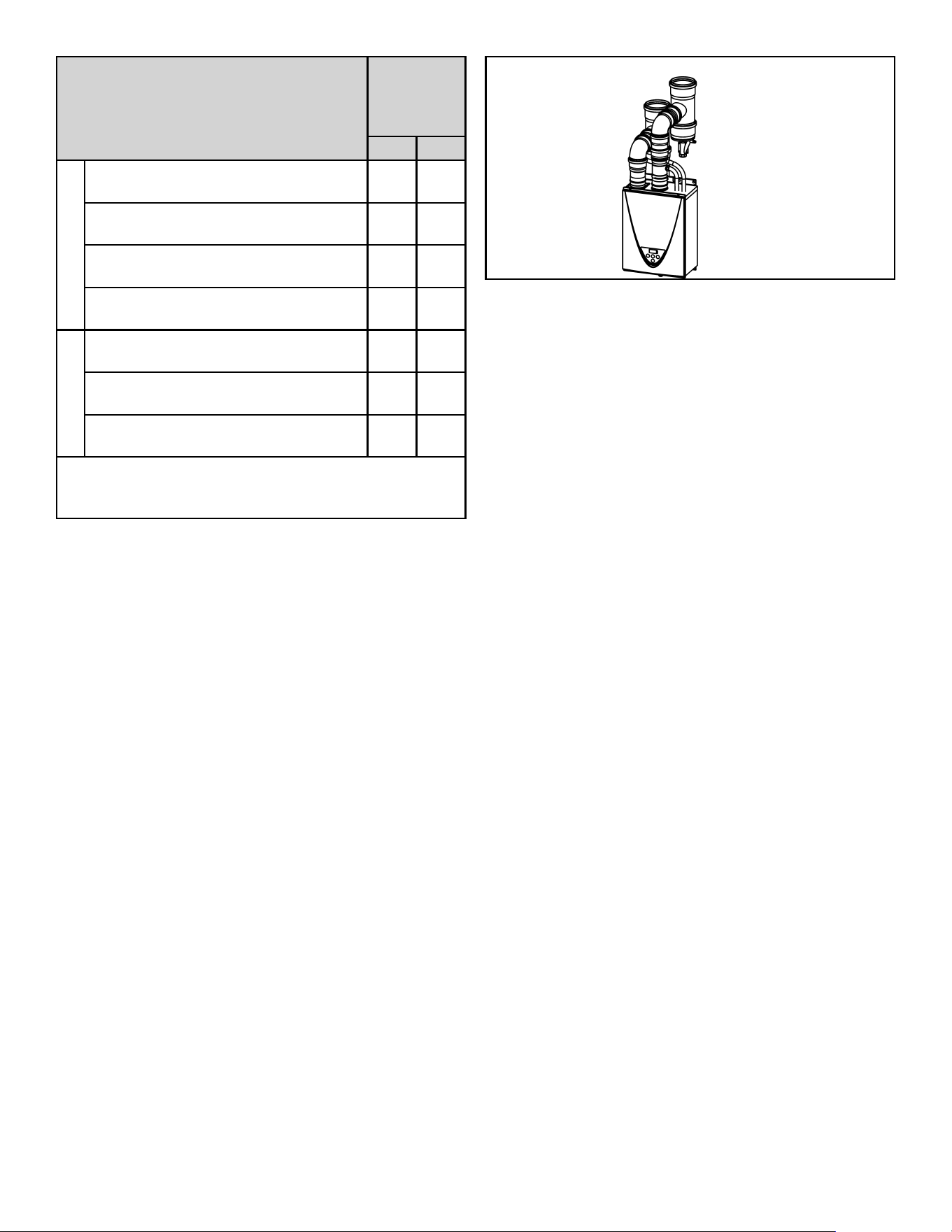
100271266 13
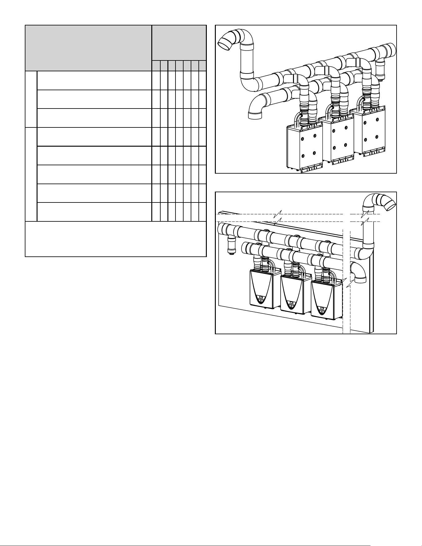
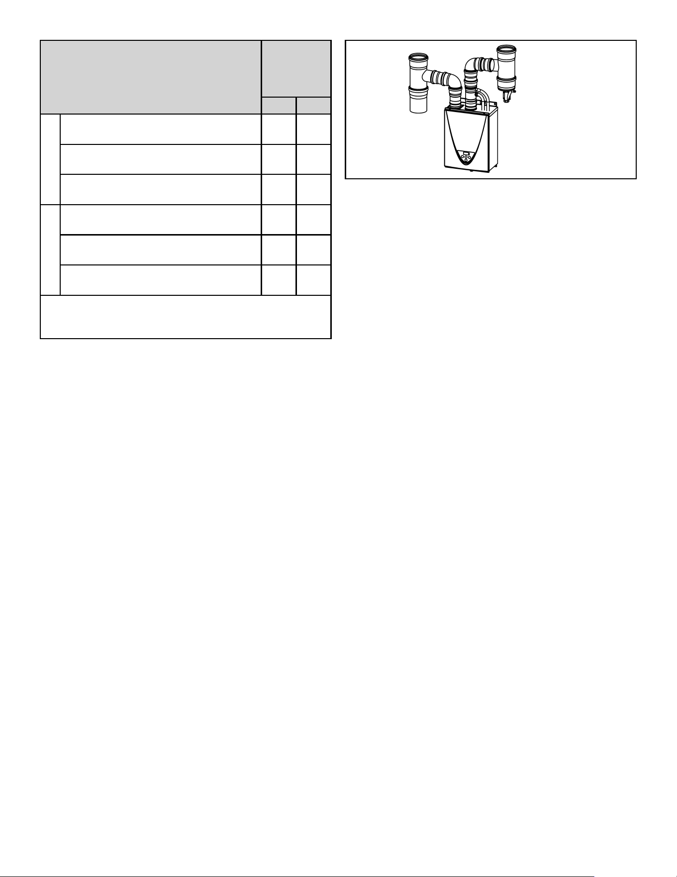
Venting Component
Number of
In-Line
Common
Vented Heaters
2345678
Air Intake
4” to 3” Reducer (PVC)
(Item #15)
2345678
4” x 90° Street Elbow (PVC)
(Item #17)
2345678
“D” x 4” Reducing Wye (PVC)
(Item #18)
2345678
Exhaust
Non-Return Valve (NRV)
(Item #14)
2345678
4” x 90° Street Elbow (PVC)
(Item #17)
2345678
“D” x 4” Reducing Wye (PVC)
(Item #18)
2345678
4” Coupling (PVC)
(Item #20)
2345678
Polypropylene to PVC adaptor
(Item #21)
2345678
* All PVC fittings and pipe shall be schedule 40.
“D” = Main Trunk Diameter.
Contractor to obtain proper pipe hangers for the venting
and air intake.
Table 3. List of Venting Components Horizontal
Configuration (In-Line)
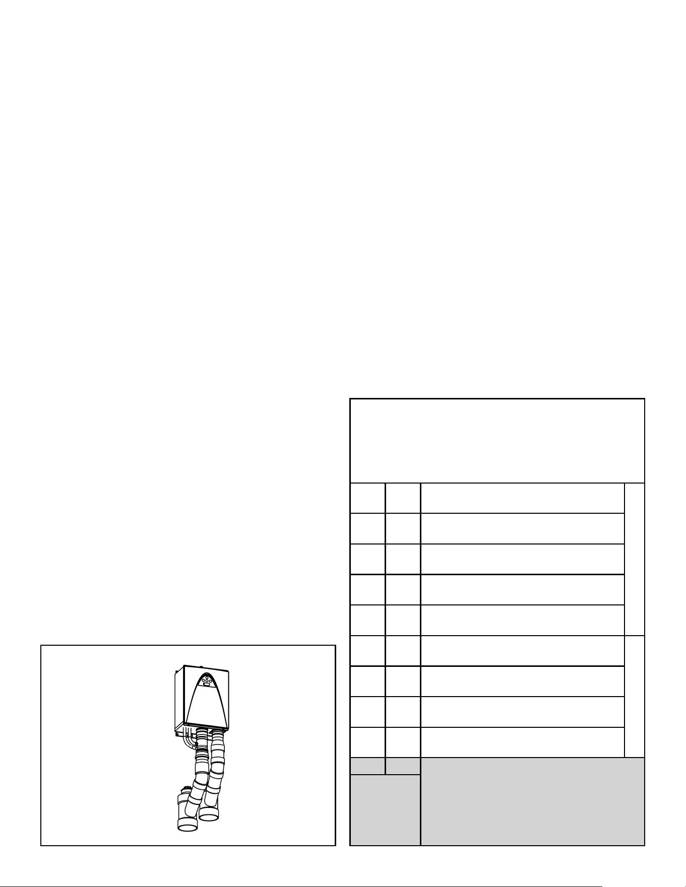
Figure 15. Horizontal Configuration (In-Line)
Figure 16. Horizontal Configuration (In-Line on Wall)
14 100271266
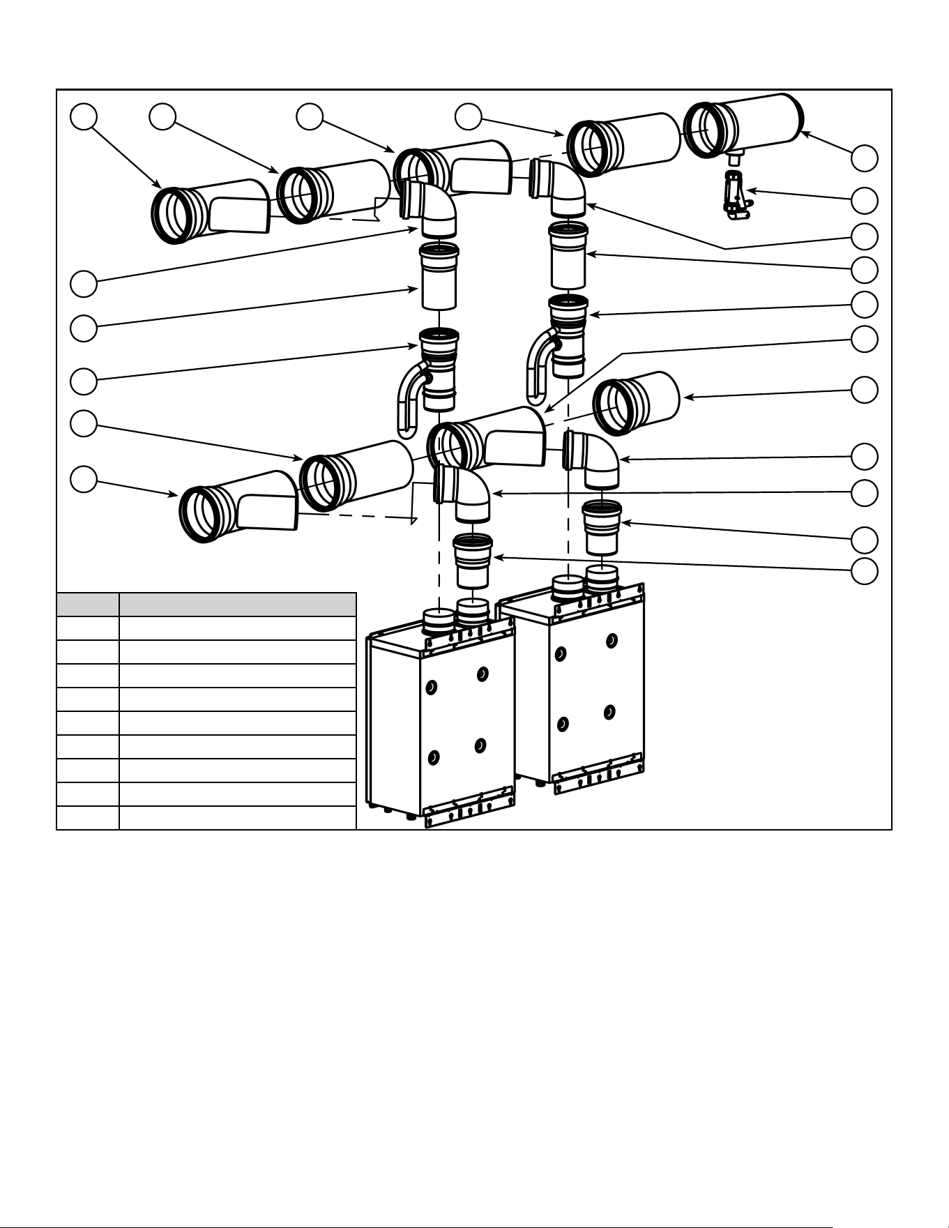
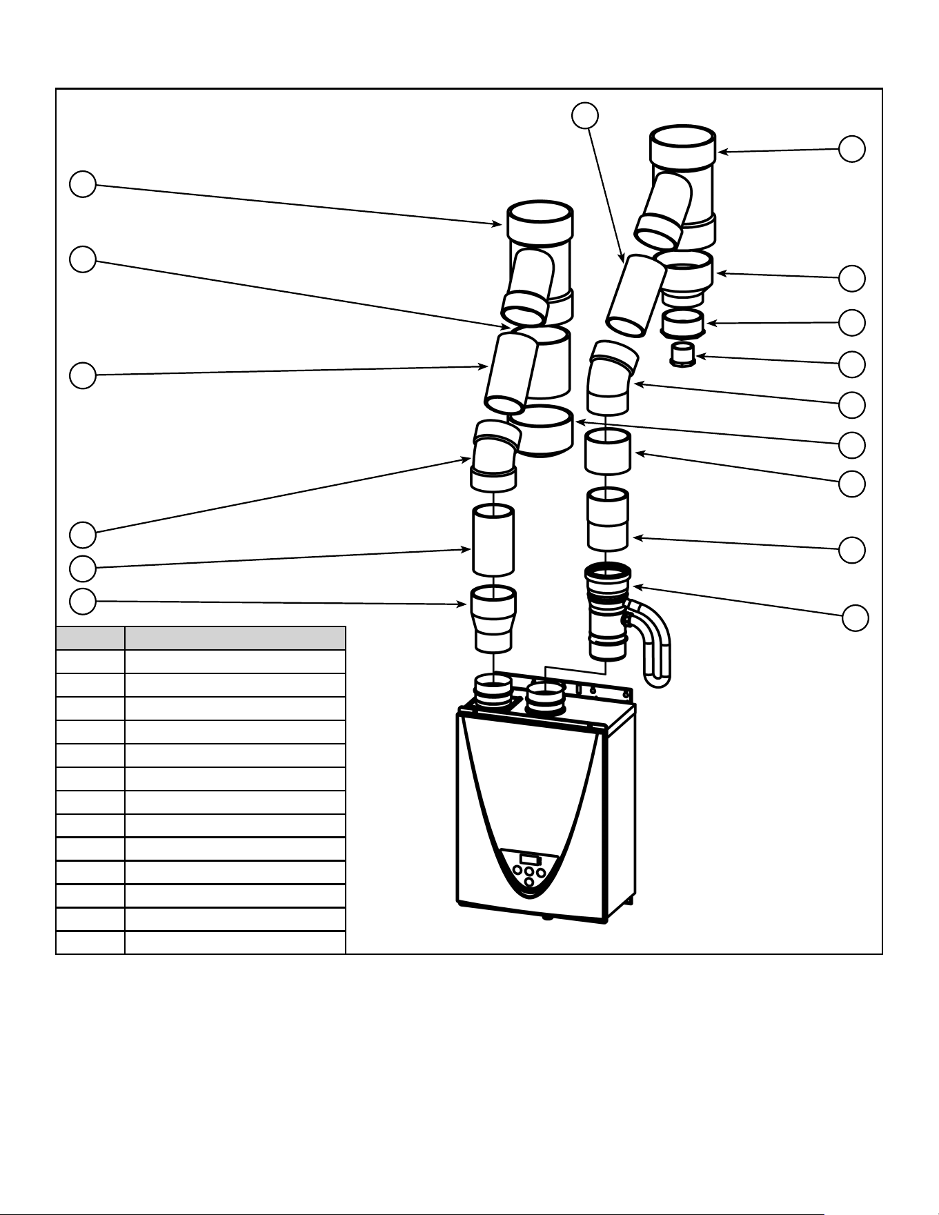
HORIZONTAL CONFIGURATIONS - (POLYPROPYLENE PIPING)
Back-To-Back
7
14
2
3
14
7
10
36
5
3
2
5
Item # Venting Component
2 100mm Adaptor
3 4” x 87° Elbow (Polypropylene)
4 “D” Endcap (Polypropylene)
5 “D” x 4” Wye (Polypropylene)
6 “D” Vent Pipe (Polypropylene)
7 4” Vent Pipe (Polypropylene)
8 “D” Endcap/Tee (Polypropylene)
9 Condensate Siphon
10 “D” x 4” Double Wye (Polypropylene)
14 Non-Return Valve (NRV)
3
9
8
4
Figure 17. Venting Components Horizontal Configuration (Back-to-Back)
100271266 15
Venting Component
Number of
Back-to-Back
Common
Vented Heaters
2345678
Air Intake
100mm Adaptor
(Item #2)
2345678
4” x 87° Elbow (Polypropylene)
(Item #3)
2345678
“D” x 4” Wye (Polypropylene)
(Item #5)
2345678
Exhaust
4” x 87° Elbow (Polypropylene)
(Item #3)
2345678
“D” x 4” Wye (Polypropylene)
(Item #5)
0101010
“D” x 4” Double Wye (Polypropylene)
(Item #10)
1122334
Non-Return Valve (NRV)
(Item #14)
2345678
“D” = Main Trunk Diameter.
Contractor to obtain proper pipe hangers for the venting
and air intake.
Table 4. List of Venting Components Horizontal
Configuration (Back-to-Back)
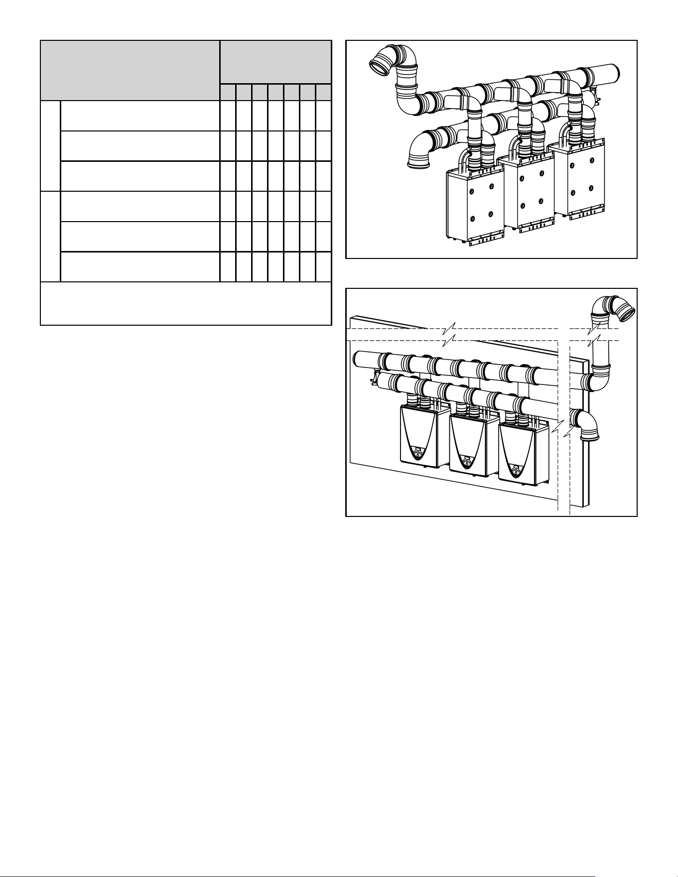
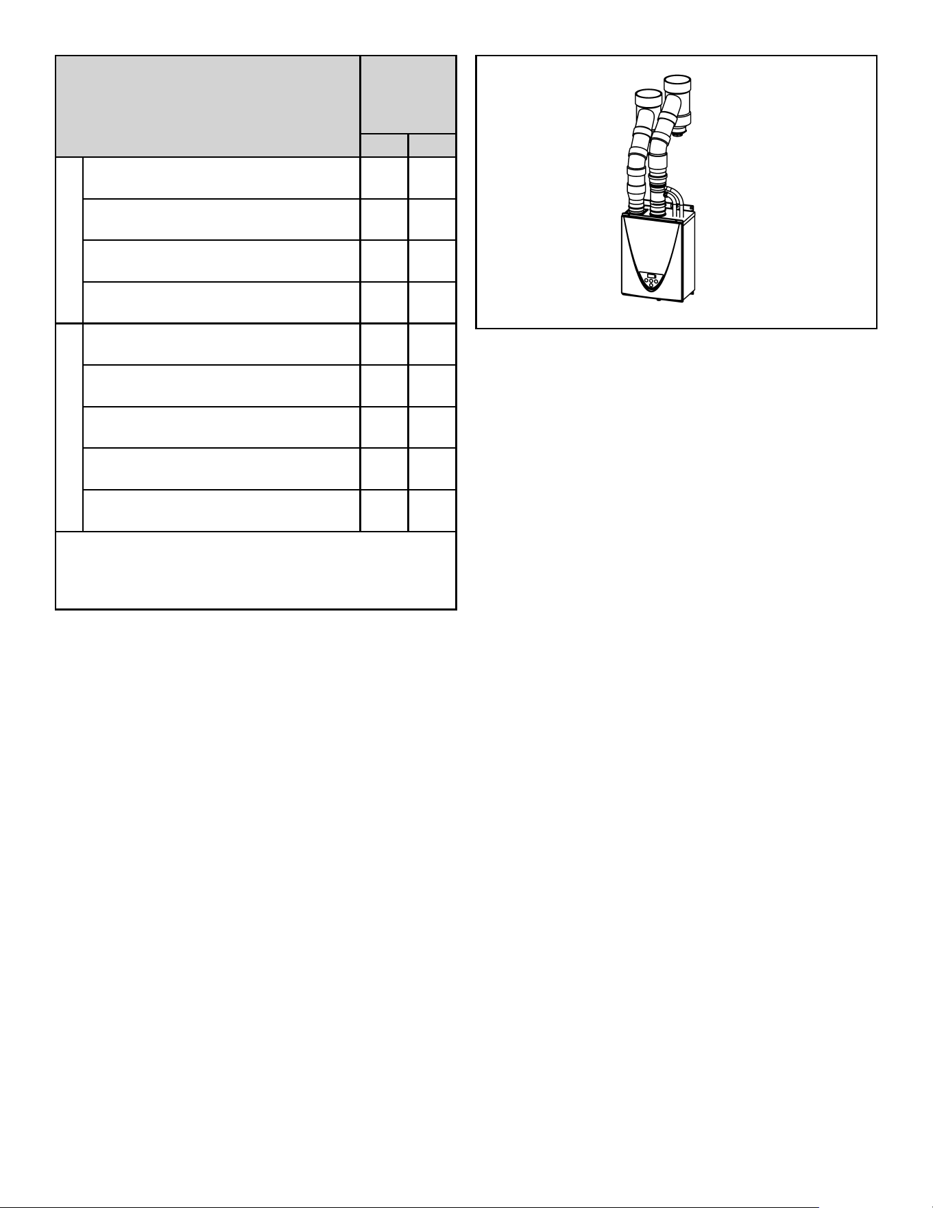
Figure 18. Horizontal Configuration (Back-to-Back)
16 100271266
In-Line
5 6
3
7
14
5
2
3
Item # Venting Component
2 100mm Adaptor
3 4” x 87° Elbow (Polypropylene)
4 “D” Endcap (Polypropylene)
5 “D” x 4” Wye (Polypropylene)
6 “D” Vent Pipe (Polypropylene)
7 4” Vent Pipe (Polypropylene)
8 “D” Endcap/Tee (Polypropylene)
9 Condensate Siphon
14 Non-Return Valve (NRV)
5 6
3
7
14
6
5
4
9
8
3
2
Figure 19. Venting Components Horizontal Configuration (In-Line)
100271266 17
Venting Component
Number of In-Line
Common Vented
Heaters
2345678
Air Intake
100mm Adaptor
(Item #2)
2345678
4” x 87° Elbow (Polypropylene)
(Item #3)
2345678
“D” x 4” Wye (Polypropylene)
(Item #5)
2345678
Exhaust
4” x 87° Elbow (Polypropylene)
(Item #3)
2345678
“D” x 4” Wye (Polypropylene)
(Item #5)
2345678
Non-Return Valve (NRV)
(Item #14)
2345678
“D” = Main Trunk Diameter.
Contractor to obtain proper pipe hangers for the venting
and air intake.
Table 5. List of Venting Components Horizontal
Configuration (In-Line)
Figure 20. Horizontal Configuration (In-Line)
Figure 21. Horizontal Configuration (In-Line on Wall)
18 100271266
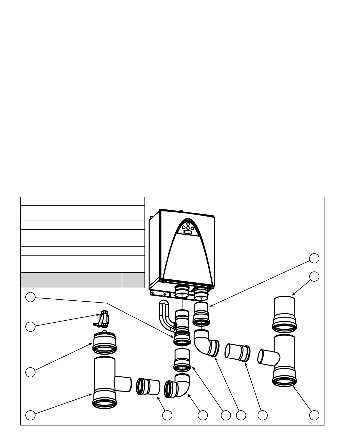
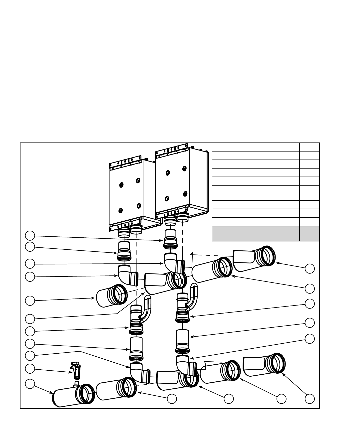
VERTICAL CONFIGURATION (SCHEDULE 40 PVC PIPING)
Dual Chase
3130
18
16
15
16
14
21
16
20
18
Item # Venting Component
14 Non-Return Valve (NRV)
15 4” to 3” Reducer (PVC)
16 4” Vent Pipe (PVC)
18 “D” x 4” Reducing Wye (PVC)
20 4” Coupling (PVC)
21 Polypropylene to PVC adaptor
22 “D” Vent Pipe (PVC)
23 2.5” x .75” NPT Adaptor (PVC)
24 4.5” x 2.5” Adaptor (PVC)
26 “D” Endcap (PVC)
28 4” x “D” Reducer (PVC)
30 4” x 45° Elbow (PVC)
31 4” x 45° Street Elbow (PVC)
26
22
23
24
28
Figure 22. Venting Components Vertical Configuration (Dual Chase)
100271266 19
Venting Component
Number of
Common
Vented
Heaters
23
Air Intake
4” to 3” Reducer (PVC)
(Item #15)
23
“D” x 4” Reducing Wye (PVC)
(Item #18)
23
4” x 45° Elbow (PVC)
(Item #30)
23
Exhaust
Non-Return Valve (NRV)
(Item #14)
23
“D” x 4” Reducing Wye (PVC)
(Item #18)
23
4” Coupling (PVC)
(Item #20)
23
Polypropylene to PVC adaptor
(Item #21)
23
4” x 45° Street Elbow (PVC)
(Item #31)
23
* All PVC fittings and pipe shall be schedule 40.
“D” = Main Trunk Diameter.
Contractor to obtain proper pipe hangers for the venting
and air intake.
Table 6. List of Venting Components Vertical
Configuration (Dual Chase)
Figure 23. Vertical Configuration (Dual Chase)
20 100271266
Single Chase
22
24
20
26
16
16
18
27
31
Item # Venting Component
14 Non-Return Valve (NRV)
15 4” to 3” Reducer (PVC)
16 4” Vent Pipe (PVC)
18 “D” x 4” Reducing Wye (PVC)
20 4” Coupling (PVC)
21 Polypropylene to PVC adaptor
22 “D” Vent Pipe (PVC)
23 2.5” x .75” NPT Adaptor (PVC)
24 4.5” x 2.5” Adaptor (PVC)
26 “D” Endcap (PVC)
27 4” x 45° Elbow (PVC)
28 4” x “D” Reducer (PVC)
31 4” x 45° Street Elbow (PVC)
23
15
14
16
28
21
18
Figure 24. Venting Components Vertical Configuration (Single Chase)
100271266 21
Venting Component
Number of
Common
Vented
Heaters
23
Air Intake
4” to 3” Reducer (PVC)
(Item #15)
23
“D” x 4” Reducing Wye (PVC)
(Item #18)
23
4” x 45° Elbow (PVC)
(Item #27)
23
4” x 45° Street Elbow (PVC)
(Item #31)
23
Exhaust
Non-Return Valve (NRV)
(Item #14)
23
“D” x 4” Reducing Wye (PVC)
(Item #18)
23
4” Coupling (PVC)
(Item #20)
23
Polypropylene to PVC adaptor
(Item #21)
23
4” x 45° Street Elbow (PVC)
(Item #31)
23
* All PVC fittings and pipe shall be schedule 40.
“D” = Main Trunk Diameter.
Contractor to obtain proper pipe hangers for the venting
and air intake.
Table 7. List of Venting Components Vertical
Configuration (Single Chase)
Figure 25. Vertical Configuration (Single Chase)
22 100271266
VERTICAL CONFIGURATION (POLYPROPYLENE PIPING)
Dual Chase
2
311
5
11737
14
7
5
Item # Venting Component
2 100mm Adaptor
3 4” x 87° Elbow (Polypropylene)
4 “D” Endcap (Polypropylene)
5 “D” x 4” Wye (Polypropylene)
7 4” Vent Pipe (Polypropylene)
9 Condensate Siphon
11 4” x 43° Elbow (Polypropylene)
13 “D” Endcap with Drain (Polypropylene)
14 Non-Return Valve (NRV)
4
13
9
Figure 26. Venting Components Vertical Configuration (Dual Chase)
100271266 23
Venting Component
Number of
Common
Vented
Heaters
23
Air Intake
100mm Adaptor
(Item #2)
23
4” x 87° Elbow (Polypropylene)
(Item #3)
23
“D” x 4” Wye (Polypropylene)
(Item #5)
23
4” x 43° Elbow (Polypropylene)
(Item #11)
23
Exhaust
4” x 87° Elbow (Polypropylene)
(Item #3)
23
“D” x 4” Wye (Polypropylene)
(Item #5)
23
4” x 43° Elbow (Polypropylene)
(Item #11)
23
Non-Return Valve (NRV)
(Item #14)
23
“D” = Main Trunk Diameter.
Contractor to obtain proper pipe hangers for the venting
and air intake.
Table 8. List of Venting Components Vertical
Configuration - Wyes (Dual Chase)
Figure 27. Vertical Configuration (Dual Chase)
24 100271266
2
3
12
7 737
14
12
Item # Venting Component
2 100mm Adaptor
3 4” x 87° Elbow (Polypropylene)
4 “D” Endcap (Polypropylene)
7 4” Vent Pipe (Polypropylene)
9 Condensate Siphon
12 “D” x 4” Reducing Tee (Polypropylene)
13 “D” Endcap with Drain (Polypropylene)
14 Non-Return Valve (NRV)
4
13
9
Figure 28. Venting Components Vertical Configuration - Tees (Dual Chase)
100271266 25
Venting Component
Number of
Common
Vented
Heaters
23
Air Intake
100mm Adaptor
(Item #2)
23
4” x 87° Elbow (Polypropylene)
(Item #3)
23
“D” x 4” Reducing Tee (Polypropylene)
(Item #12)
23
Exhaust
4” x 87° Elbow (Polypropylene)
(Item #3)
23
Non-Return Valve (NRV)
(Item #14)
23
“D” x 4” Reducing Tee (Polypropylene)
(Item #12)
23
“D” = Main Trunk Diameter.
Contractor to obtain proper pipe hangers for the venting
and air intake.
Table 9. List of Venting Components Vertical
Configuration - Tees (Dual Chase)
Figure 29. Vertical Configuration - Tees (Dual Chase)
26 100271266
Single Chase
2
11
7
5 74 5
11
Item # Venting Component
2 100mm Adaptor
4 “D” Endcap (Polypropylene)
5 “D” x 4” Wye (Polypropylene)
7 4” Vent Pipe (Polypropylene)
9 Condensate Siphon
11 4” x 43° Elbow (Polypropylene)
13 “D” Endcap with Drain (Polypropylene)
14 Non-Return Valve (NRV)
13
9
14
Figure 30. Venting Components Vertical Configuration - Wyes (Single Chase)
100271266 27
Venting Component
Number of
Common
Vented
Heaters
23
Air Intake
100mm Adaptor
(Item #2)
23
“D” Endcap (Polypropylene)
(Item #4)
23
4” x 43° Elbow (Polypropylene)
(Item #11)
46
Exhaust
“D” x 4” Wye (Polypropylene)
(Item #5)
23
4” x 43° Elbow (Polypropylene)
(Item #11)
23
Non-Return Valve (NRV)
(Item #14)
23
“D” = Main Trunk Diameter.
Contractor to obtain proper pipe hangers for the venting
and air intake.
Table 10. List of Venting Components Vertical
Configuration - Wyes (Single Chase)
Figure 31. Vertical Configuration - Wyes (Single Chase)
28 100271266
2
3
7
7
12 123
14
4
7
Item # Venting Component
2 100mm Adaptor
3 4” x 87° Elbow (Polypropylene)
4 “D” Endcap (Polypropylene)
7 4” Vent Pipe (Polypropylene)
9 Condensate Siphon
12 “D” x 4” Reducing Tee (Polypropylene)
13 “D” Endcap with Drain (Polypropylene)
14 Non-Return Valve (NRV)
13
9
Figure 32. Venting Components Vertical Configuration - Tees (Single Chase)
100271266 29
Venting Component
Number of
Common
Vented
Heaters
23
Air Intake
100mm Adaptor
(Item #2)
23
4” x 87° Elbow (Polypropylene)
(Item #3)
23
4” x 43° Elbow (Polypropylene)
(Item #11)
23
“D” x 4” Reducing Tee (Polypropylene)
(Item #12)
23
Exhaust
4” x 87° Elbow (Polypropylene)
(Item #3)
23
“D” x 4” Reducing Tee (Polypropylene)
(Item #12)
23
Non-Return Valve (NRV)
(Item #14)
23
“D” = Main Trunk Diameter.
Contractor to obtain proper pipe hangers for the venting
and air intake.
Table 11. List of Venting Components Vertical
Configuration - Tees (Single Chase)
Figure 33. Vertical Configuration - Tees (Single Chase)
30 100271266
ITEM LIST
1 Heater
2 100mm Adaptor
3 4” x 87° Elbow (Polypropylene)
4 “D” Endcap (Polypropylene)
5 “D” x 4” Wye (Polypropylene)
6 “D” Vent Pipe (Polypropylene)
7 4” Vent Pipe (Polypropylene)
8 “D” Endcap/Tee (Polypropylene)
9 Condensate Siphon
10 “D” x 4” Double Wye (Polypropylene)
11 4” x 43° Elbow (Polypropylene)
12 “D” x 4” Reducing Tee
(Polypropylene)
13 “D” Endcap with Drain
(Polypropylene)
14 Non-Return Valve (NRV)
(100113130)
15 4” to 3” Reducer (PVC)
16 4” Vent Pipe (PVC)
17 4” x 90° Street Elbow (PVC)
18 “D” x 4” Reducing Wye (PVC)
19 “D” x 4” Double Wye (PVC)
20 4” Coupling (PVC)
21 Polypropylene to PVC adaptor
(100113129)
22 “D” Vent Pipe (PVC)
23 2.5” x .75” NPT Adaptor (PVC)
24 4.5” x 2.5” Adaptor (PVC)
25 4” x 5” Reducer (PVC)
26 “D” Endcap (PVC)
27 4” x 45° Elbow (PVC)
28 4” x “D” Reducer (PVC)
29 “D” x 4” Reducing Tee (PVC)
30 4” x 45° Elbow (PVC)
31 4” x 45° Street Elbow (PVC)
“D” = Main Trunk Diameter.
FINAL CHECKLIST
Non-Return Valve (NRV) installed on each heater.
PVC Adaptor installed on each heater with PVC venting.
Venting properly supported.
Venting properly sloped.
Venting condensate drain installed.
30 100271266
LISTE DE COMPOSANTES
1 Réservoir
2 Adaptateur 100 mm
3 Coude 4” x 87° (polypropylène)
4 Capuchon “D” (polypropylène)
5 Réducteur 3 voies “D” x 4”
(polypropylène)
6 Conduit “D” (polypropylène)
7 Conduit 4” (polypropylène)
8 Capuchon/Té “D” (polypropylène)
9 Siphon de condensation
10 Réducteur 4 voies “D” x 4”
(polypropylène)
11 Coude 4” x 43° (polypropylène)
12 Té réducteur “D” x 4”
(polypropylène)
13 Capuchon “D” avec drain
(polypropylène)
14 Clapet de non-retour
(100113130)
15 Réducteur 4” x 3” (PVC)
16 Conduit 4” (PVC)
17 Coude mâle/femelle (street)
4” x 90° (PVC)
18 Réducteur 3 voies (Y) “D” x 4”
(PVC)
19 Réducteur 4 voies (Y) “D” x 4”
(PVC)
20 Manchon 4” (PVC)
21 Adaptateur polypropylène
à PVC
(100113129)
22 Conduit “D” (PVC)
23 Adaptateur 2,5” x 0,75” NPT
(PVC)
24 Adaptateur 4,5” x 2,5” (PVC)
25 Réducteur 4” x 5” (PVC)
26 Capuchon “D” (PVC)
27 Coude 4” x 45° (PVC)
28 Réducteur 4” x “D” (PVC)
29 Té réducteur “D” x 4” (PVC)
30 Coude 4” x 45° (PVC)
31 Coude mâle/femelle (street)
4” x 45° (PVC)
“D” = Diamètre du conduit commun
LISTE DE VÉRIFICATION FINALE
Clapet de non-retour installé sur chaque chauffe-eau.
Adaptateur pour le PVC installé sur chaque chauffe-eau
avec conduits de ventilation en PVC.
Conduits correctement supportés.
Conduits avec pente adéquate.
Le drain de condensation est installé sur le conduit
d’évacuation.
100271266 29
Composante de ventilation
No. de
chauffe-
eau à
ventilation
commune
23
Apport d’air
Adaptateur 100 mm
(Item #2)
23
Coude 4” x 87° (polypropylène)
(Item #3)
23
Coude 4” x 43° (polypropylène)
(Item #11)
23
Té réducteur “D” x 4” (polypropylène)
(Item #12)
23
Évacuation
Coude 4” x 87° (polypropylène)
(Item #3)
23
Té réducteur “D” x 4” (polypropylène)
(Item #12)
23
Clapet de non-retour
(Item #14)
23
“D” = Diamètre du conduit commun
L'installateur doit fournir les sangles requises pour
le support des conduits d'approvisionnement et
d'évacuation.
Tableau 11. Liste de composantes de ventilation,
configuration verticale - Tés (gaine ou
puits unique)
Figure 33. Configuration verticale - Tés (gaine ou puits
unique)
28 100271266
2
3
7
7
12 123
14
4
7
No.
item
Composante de ventilation
2 Adaptateur 100 mm
3 Coude 4” x 87° (polypropylène)
4 Capuchon “D” (polypropylène)
7 Conduit 4” (polypropylène)
9 Siphon de condensation
12 Té réducteur “D” x 4” (polypropylène)
13 Capuchon “D” avec drain
(polypropylène)
14 Clapet de non-retour
13
9
Figure 32. Composantes, configuration verticale - Tés (gaine ou puits unique)
100271266 27
Composante de ventilation
No. de
chauffe-
eau à
ventilation
commune
23
Apport d’air
Adaptateur 100 mm
(Item #2)
23
Capuchon “D” (polypropylène)
(Item #4)
23
Coude 4” x 43° (polypropylène)
(Item #11)
46
Évacuation
Réducteur 3 voies “D” x 4”
(polypropylène) (Item #5)
23
Coude 4” x 43° (polypropylène)
(Item #11)
23
Clapet de non-retour
(Item #14)
23
“D” = Diamètre du conduit commun
L'installateur doit fournir les sangles requises pour
le support des conduits d'approvisionnement et
d'évacuation.
Tableau 10. Liste de composantes de ventilation,
configuration verticale - 3 voies (Y) (gaine
ou puits unique)
Figure 31. Configuration verticale - 3 voies (Y) (gaine
ou puits unique)
26 100271266
Gaine ou puits unique
2
11
7
5 74 5
11
No.
item
Composante de ventilation
2 Adaptateur 100 mm
4 Capuchon “D” (polypropylène)
5 Réducteur 3 voies “D” x 4”
(polypropylène)
7 Conduit 4” (polypropylène)
9 Siphon de condensation
11 Coude 4” x 43° (polypropylène)
13 Capuchon “D” avec drain
(polypropylène)
14 Clapet de non-retour
13
9
14
Figure 30. Composantes, configuration verticale - 3 voies (Y) (gaine ou puits unique)
100271266 25
Composante de ventilation
No. de
chauffe-
eau à
ventilation
commune
23
Apport d’air
Adaptateur 100 mm
(Item #2)
23
Coude 4” x 87° (polypropylène)
(Item #3)
23
Té réducteur “D” x 4” (polypropylène)
(Item #12)
23
Évacuation
Coude 4” x 87° (polypropylène)
(Item #3)
23
Clapet de non-retour
(Item #14)
23
Té réducteur “D” x 4” (polypropylène)
(Item #12)
23
“D” = Diamètre du conduit commun
L'installateur doit fournir les sangles requises pour
le support des conduits d'approvisionnement et
d'évacuation.
Tableau 9. Liste de composantes de ventilation,
configuration verticale - Tés (gaines ou
puits séparés)
Figure 29. Configuration verticale - Tés (gaines ou puits
séparés)
24 100271266
2
3
12
7 737
14
12
No.
item
Composante de ventilation
2 Adaptateur 100 mm
3 Coude 4” x 87° (polypropylène)
4 Capuchon “D” (polypropylène)
7 Conduit 4” (polypropylène)
9 Siphon de condensation
12 Té réducteur “D” x 4” (polypropylène)
13 Capuchon “D” avec drain
(polypropylène)
14 Clapet de non-retour
4
13
9
Figure 28. Composantes, configuration verticale - Tés (gaines ou puits séparés)
100271266 23
Composante de ventilation
No. de
chauffe-
eau à
ventilation
commune
23
Apport d’air
Adaptateur 100 mm
(Item #2)
23
Coude 4” x 87° (polypropylène)
(Item #3)
23
Réducteur 3 voies “D” x 4”
(polypropylène) (Item #5)
23
Coude 4” x 43° (polypropylène)
(Item #11)
23
Évacuation
Coude 4” x 87° (polypropylène)
(Item #3)
23
Réducteur 3 voies “D” x 4”
(polypropylène) (Item #5)
23
Coude 4” x 43° (polypropylène)
(Item #11)
23
Clapet de non-retour
(Item #14)
23
“D” = Diamètre du conduit commun
L'installateur doit fournir les sangles requises pour
le support des conduits d'approvisionnement et
d'évacuation.
Tableau 8. Liste de composantes de ventilation,
configuration verticale - 3 voies (Y)
(gaines ou puits séparés)
Figure 27. Configuration verticale (gaines ou puits
séparés)
22 100271266
CONFIGURATION VERTICALE (CONDUIT EN POLYPROPYLÈNE)
Gaines ou puits séparés
2
311
5
11737
14
7
5
No.
item
Composante de ventilation
2 Adaptateur 100 mm
3 Coude 4” x 87° (polypropylène)
4 Capuchon “D” (polypropylène)
5 Réducteur 3 voies “D” x 4”
(polypropylène)
7 Conduit 4” (polypropylène)
9 Siphon de condensation
11 Coude 4” x 43° (polypropylène)
13 Capuchon “D” avec drain
(polypropylène)
14 Clapet de non-retour
4
13
9
Figure 26. Composantes, configuration verticale (gaines ou puits séparés)
100271266 21
Composante de ventilation
No. de
chauffe-
eau à
ventilation
commune
23
Apport d’air
Réducteur 4” x 3” (PVC)
(Item #15)
23
Réducteur 3 voies (Y) “D” x 4”
(PVC) (Item #18)
23
Coude 4” x 45° (PVC)
(Item #27)
23
Coude mâle/femelle (street)
4” x 45° (PVC) (Item #31)
23
Évacuation
Clapet de non-retour
(Item #14)
23
Réducteur 3 voies (Y) “D” x 4”
(PVC) (Item #18)
23
Manchon 4” (PVC)
(Item #20)
23
Adaptateur polypropylène
à PVC (Item #21)
23
Coude mâle/femelle (street)
4” x 45° (PVC) (Item #31)
23
* Tous les conduits et raccords en PVC doivent être de
calibre Schedule 40.
“D” = Diamètre du conduit commun
L'installateur doit fournir les sangles requises pour
le support des conduits d'approvisionnement et
d'évacuation.
Tableau 7. Liste des composantes de ventilation,
configuration verticale (gaine ou puits
unique)
Figure 25. Configuration verticale (gaine ou puits
unique)
20 100271266
Gaine ou puits unique
22
24
20
26
16
16
18
27
31
No. item Composante de ventilation
14 Clapet de non-retour
15 Réducteur 4” x 3” (PVC)
16 Conduit 4” (PVC)
18 Réducteur 3 voies (Y) “D” x 4”
(PVC)
20 Manchon 4” (PVC)
21 Adaptateur polypropylène
à PVC
22 Conduit “D” (PVC)
23 Adaptateur 2,5” x 0,75” NPT
(PVC)
24 Adaptateur 4,5” x 2,5” (PVC)
26 Capuchon “D” (PVC)
27 Coude 4” x 45° (PVC)
28 Réducteur 4” x “D” (PVC)
31 Coude mâle/femelle (street)
4” x 45° (PVC)
23
15
14
16
28
21
18
Figure 24. Composantes, configuration verticale (gaine ou puits unique)
100271266 19
Composante de ventilation
No. de
chauffe-
eau à
ventilation
commune
23
Apport d’air
Réducteur 4” x 3” (PVC)
(Item #15)
23
Réducteur 3 voies (Y) “D” x 4”
(PVC) (Item #18)
23
Coude 4” x 45° (PVC)
(Item #30)
23
Évacuation
Clapet de non-retour
(Item #14)
23
Réducteur 3 voies (Y) “D” x 4”
(PVC) (Item #18)
23
Manchon 4” (PVC)
(Item #20)
23
Adaptateur polypropylène
à PVC (Item #21)
23
Coude mâle/femelle (street)
4” x 45° (PVC) (Item #31)
23
* Tous les conduits et raccords en PVC doivent être de
calibre Schedule 40.
“D” = Diamètre du conduit commun
L'installateur doit fournir les sangles requises pour
le support des conduits d'approvisionnement et
d'évacuation.
Tableau 6. Liste des composantes de ventilation,
configuration verticale (gaines ou puits
séparés)
Figure 23. Configuration verticale (gaines ou puits
séparés)
18 100271266
CONFIGURATION VERTICALE (CONDUIT EN PVC SCHEDULE 40)
Gaines ou puits séparés
3130
18
16
15
16
14
21
16
20
18
No. item Composante de ventilation
14 Clapet de non-retour
15 Réducteur 4” x 3” (PVC)
16 Conduit 4” (PVC)
18 Réducteur 3 voies (Y) “D” x 4”
(PVC)
20 Manchon 4” (PVC)
21 Adaptateur polypropylène
à PVC
22 Conduit “D” (PVC)
23 Adaptateur 2,5” x 0,75” NPT
(PVC)
24 Adaptateur 4,5” x 2,5” (PVC)
26 Capuchon “D” (PVC)
28 Réducteur 4” x “D” (PVC)
30 Coude 4” x 45° (PVC)
31 Coude mâle/femelle (street)
4” x 45° (PVC)
26
22
23
24
28
Figure 22. Composantes, configuration verticale (gaines ou puits séparés)
100271266 17
Composante de ventilation
No. de
chauffe-eau
côte à côte
à ventilation
commune
2345678
Apport d’air
Adaptateur 100 mm
(Item #2)
2345678
Coude 4” x 87° (polypropylène)
(Item #3)
2345678
Réducteur 3 voies “D” x 4”
(polypropylène) (Item #5)
2345678
Évacuation
Coude 4” x 87° (polypropylène)
(Item #3)
2345678
Réducteur 3 voies “D” x 4”
(polypropylène) (Item #5)
2345678
Clapet de non-retour
(Item #14)
2345678
“D” = Diamètre du conduit commun
L'installateur doit fournir les sangles requises pour
le support des conduits d'approvisionnement et
d'évacuation.
Tableau 5. Liste des composantes de ventilation,
configuration horizontale (côte à côte)
Figure 20. Configuration horizontale (côte à côte)
Figure 21. Configuration horizontale (côte à côte, mur)
16 100271266
Côte à côte
5 6
3
7
14
5
2
3
No.
item
Composante de ventilation
2 Adaptateur 100 mm
3 Coude 4” x 87° (polypropylène)
4 Capuchon “D” (polypropylène)
5 Réducteur 3 voies “D” x 4”
(polypropylène)
6 Conduit “D” (polypropylène)
7 Conduit 4” (polypropylène)
8 Capuchon/Té “D” (polypropylène)
9 Siphon de condensation
14 Clapet de non-retour
5 6
3
7
14
6
5
4
9
8
3
2
Figure 19. Composantes, configuration horizontale (côte à côte)
100271266 15
Composante de ventilation
No. de chauffe-
eau dos à dos
à ventilation
commune
2345678
Apport d’air
Adaptateur 100 mm
(Item #2)
2345678
Coude 4” x 87° (polypropylène)
(Item #3)
2345678
Réducteur 3 voies “D” x 4”
(polypropylène)
(Item #5)
2345678
Évacuation
Coude 4” x 87° (polypropylène)
(Item #3)
2345678
Réducteur 3 voies “D” x 4”
(polypropylène) (Item #5)
0101010
Réducteur 4 voies “D” x 4”
(polypropylène) (Item #10)
1122334
Clapet de non-retour
(Item #14)
2345678
“D” = Diamètre du conduit commun
L'installateur doit fournir les sangles requises pour
le support des conduits d'approvisionnement et
d'évacuation.
Tableau 4. Liste des composantes de ventilation,
configuration horizontale (dos à dos)
Figure 18. Configuration horizontale (dos à dos)
14 100271266
CONFIGURATION HORIZONTALE - (CONDUIT EN POLYPROPYLÈNE)
Dos à dos
7
14
2
3
14
7
10
36
5
3
2
5
No. item Composante de ventilation
2 Adaptateur 100 mm
3 Coude 4” x 87° (polypropylène)
4 Capuchon “D” (polypropylène)
5 Réducteur 3 voies “D” x 4”
(polypropylène)
6 Conduit “D” (polypropylène)
7 Conduit 4” (polypropylène)
8 Capuchon/Té “D” (polypropylène)
9 Siphon de condensation
10 Réducteur 4 voies “D” x 4”
(polypropylène)
14 Clapet de non-retour
3
9
8
4
Figure 17. Composantes, configuration horizontale (dos à dos)
100271266 13
Composante de ventilation
No. de chauffe-
eau
côte à côte
à ventilation
commune
2345678
Apport d’air
Réducteur 4” x 3” (PVC)
(Item #15)
2345678
Coude mâle/femelle (street)
4” x 90° (PVC) (Item #17)
2345678
Réducteur 3 voies (Y) “D” x 4”
(PVC) (Item #18)
2345678
Évacuation
Clapet de non-retour
(Item #14)
2345678
Coude mâle/femelle (street)
4” x 90° (PVC) (Item #17)
2345678
Réducteur 3 voies (Y) “D” x 4”
(PVC) (Item #18)
2345678
Manchon 4” (PVC)
(Item #20)
2345678
Adaptateur polypropylène
à PVC (Item #21)
2345678
* Tous les conduits et raccords en PVC doivent être de
calibre Schedule 40.
“D” = Diamètre du conduit commun
L'installateur doit fournir les sangles requises pour
le support des conduits d'approvisionnement et
d'évacuation.
Tableau 3. Liste des composantes de ventilation,
configuration horizontale (côte à côte)
Figure 15. Configuration horizontale (côte à côte)
Figure 16. Configuration horizontale (côte à côte, mur)
12 100271266
Côte à côte
22
16
16
14
21
20
1822
17
16
22
29
18
15
17
No.
item
Composante de ventilation
14 Clapet de non-retour
15 Réducteur 4” x 3” (PVC)
16 Conduit 4” (PVC)
17 Coude mâle/femelle (street)
4” x 90° (PVC)
18 Réducteur 3 voies (Y) “D” x 4”
(PVC)
20 Manchon 4” (PVC)
21 Adaptateur polypropylène
à PVC
22 Conduit “D” (PVC)
23 Adaptateur 2,5” x 0,75” NPT
(PVC)
24 Adaptateur 4,5” x 2,5” (PVC)
25 Réducteur 4” x 5” (PVC)
26 Capuchon “D” (PVC)
29 Té réducteur “D” x 4” (PVC)
22 18 17
16
20
21
14
17
22
18
16
15
26
25
24
23
26
Figure 14. Composantes, configuration horizontale (côte à côte)
100271266 11
Composante de ventilation
No. de chauffe-
eau dos à dos
à ventilation
commune
2345678
Apport d’air
Réducteur 4” x 3” (PVC)
(Item #15)
2345678
Coude mâle/femelle (street)
4” x 90° (PVC) (Item #17)
2345678
Réducteur 3 voies (Y) “D” x 4”
(PVC) (Item #18)
2345678
Évacuation
Clapet de non-retour
(Item #14)
2345678
Coude mâle/femelle (street)
4” x 90° (PVC) (Item #17)
2345678
Réducteur 3 voies (Y) “D” x 4”
(PVC) (Item #18)
0101010
Réducteur 4 voies (Y) “D” x 4”
(PVC) (Item #19)
1122334
Manchon 4” (PVC)
(Item #20)
2345678
Adaptateur polypropylène
à PVC (Item #21)
2345678
* Tous les conduits et raccords en PVC doivent être de
calibre Schedule 40.
“D” = Diamètre du conduit commun
L'installateur doit fournir les sangles requises pour
le support des conduits d'approvisionnement et
d'évacuation.
Tableau 2. Liste des composantes de ventilation,
configuration horizontale (dos à dos)
Figure 13. Configuration horizontale (dos à dos)
10 100271266
VENTILATION
Les pages suivantes présentent les vues en éclaté de toutes les configurations de ventilation possibles (horizontales et
verticales), avec des conduits en PVC et en polypropylène. Chacune de ces figures contient aussi un tableau qui présente
le nombre de composantes requises en fonction du nombre de chauffe-eau raccordés en ventilation commune.
CONFIGURATION HORIZONTALE - (CONDUIT EN PVC SCHEDULE 40)
Dos à dos
24
22
17
16
15
15
21
22
14
20
16
17 221922
1718
20
16
17
18
21
14
22
25
16
16
No.
item
Composante de ventilation
14 Clapet de non-retour
15 Réducteur 4” x 3” (PVC)
16 Conduit 4” (PVC)
17 Coude mâle/femelle (street)
4” x 90° (PVC)
18 Réducteur 3 voies (Y) “D” x 4”
(PVC)
19 Réducteur 4 voies (Y) “D” x 4”
(PVC)
20 Manchon 4” (PVC)
21 Adaptateur polypropylène
à PVC
22 Conduit “D” (PVC)
23 Adaptateur 2,5” x 0,75” NPT
(PVC)
24 Adaptateur 4,5” x 2,5” (PVC)
25 Réducteur 4” x 5” (PVC)
26 Capuchon “D” (PVC)
29 Té réducteur “D” x 4” (PVC)
26
2922
23
26
Figure 12. Composantes, configuration horizontale (dos à dos)
100271266 9
Configuration verticale
En configuration verticale (multiniveau), le nombre maximal
de chauffe-eau à ventilation commune est de 3. La longueur
équivalente maximale d'un conduit de ventilation commune
à la verticale est de 100 pi (30 m) s'il possède un diamètre
de 8 po sur toute sa longueur.
Voici les autres exigences de dimensionnement à respecter
(approvisionnement et évacuation) (voir Figure 11):
• L
1
+ L
2
≤ 10 pi + 2 coude, max.
• Longueur totale du conduit = L
1
+ L
2
+ H
t
H
1
H
2
H
t
L
2
L
1
90° 45°
“T”
Note: conduit d’approvisionnement
d’air non illustré; le calcul du
dimensionnement est identique
à celui de l’évacuation; il doit
obligatoirement être installé. Une
installation avec le seul conduit
d’évacuation n’est pas admissible.
Figure 11. Dimensionnement des conduits
DÉGAGEMENTS
NOTE: respectez les distances de dégagement des
terminaisons spécifiées dans les codes locaux et nationaux.
En l’absence de codes locaux, les distances de dégagement
spécifiées ci-dessous peuvent être utilisées. Les codes locaux
ont priorité sur les distances de dégagement présentées ci-
dessous.
Terminaisons à travers le mur
Dans le cas où on retrouve plusieurs terminaisons d'évacuation
murales (ex.: système multi chauffe-eau), les terminaisons
d'évacuation doivent se trouver à au moins 1 pi (305 mm) les
unes des autres. Toute terminaison d’évacuation doit aussi
se trouver à au moins 2 pi (610 mm) d’un coin intérieur. Si
le mur adjacent a une longueur inférieure à 2 pi (610 mm), la
terminaison ne peut se terminer à une distance inférieure à
celle du mur adjacent.
Dans le cas d'une terminaison d'évacuation directe murale
faisant appel à deux conduits séparés (approvisionnement et
évacuation), veuillez respecter les distances de dégagement
indiquées dans le Manuel d’installation et Guide du
propriétaire.
La terminaison d’évacuation ou la terminaison concentrique
d'un appareil à évacuation directe doit se trouver à au moins
2 pi (610 mm) d’un mur ou d’une surface opposée. Une
terminaison ne doit jamais être installée devant une ouverture
d’un bâtiment.
Terminaisons à travers le toit
Toute terminaison d’évacuation doit se trouver à au moins
1 pi (305 mm) de toute obstruction.
1. Distances de dégagement entre plusieurs terminaisons
d'approvisionnement et d'évacuation – à travers le mur
ou le toit): respectez les dégagements illustrés dans
les diagrammes du Manuel d’installation et Guide du
propriétaire.
8 100271266
Figure 9. Ventilation verticale dans une gaine ou un
puits unique
ÉTABLISSEMENT DU DIAMÈTRE DES CONDUITS
COMMUNS
Configuration horizontale
Pour établir le diamètre du conduit de ventilation commun (D),
il faut d'abord connaître la longueur équivalente totale des
conduits de raccordement, ainsi que le nombre de chauffe-
eau. La longueur équivalente totale (L) est la somme de la
plus longue distance horizontale (H) et de la longueur verticale
(V), plus une longueur équivalente de 5 pi (1,5 m) pour chacun
des coudes à 90° (deux max.).
Apport
d’air
Évacuation
Clapet de
non-retour
"V"
"H"
"D"
Figure 10. Dimensionnement des conduits
Notes:
• Longueur équivalente totale (L) = H + V + (nb de coude
x 5) (en pieds)
• Diamètre conduit=”D”
• Pour connaître l'écart minimal entre la terminaison du
conduit d'évacuation et celle d'approvisionnement d'air,
reportez-vous au Manuel d’installation et Guide du
propriétaire.
• Une fois connue la longueur L, Figure 3reportez-vous à
la Figure 3 pour trouver le diamètre requis pour le conduit
de ventilation commune. À noter: il faut aussi considérer
le nombre de chauffe-eau raccordés au conduit de
ventilation commune. Par exemple, pour 4 chauffe-eau
et une longueur L de 60 pi (18 m), le conduit de ventilation
commune doit avoir un diamètre de 8 po.
• La procédure est la même tant pour l'approvisionnement
d'air que l'évacuation.
• Installez une grille anti-vermine dans chacune des
terminaisons afin de bloquer l'entrée de tout corps
étranger (la grille doit avoir un quadrillé minimum de 3/4 po
(19 mm)).
100271266 7
admissible entre le chauffe-eau et le conduit commun principal
est de 10 pi (3 m), avec seulement deux coudes Le conduit
de raccordement au conduit commun doit avoir un diamètre
de 4 po.
Figure 7. Ventilation verticale à travers le toit
Apport
d’air
Évacuation
3 pi
MIN
Figure 8. Ventilation verticale à travers le mur
6 100271266
TYPES DE VENTILATION COMMUNE
Horizontal (côte à côte)
Il est possible de raccorder jusqu'à 8 chauffe-eau à
condensation à un conduit de ventilation commune, en
configuration côte à côte ou dos à dos. Il est préférable
d'effectuer le raccordement au conduit commun à l'aide d'un
raccord réducteur à 3 voies (Y), mais il est acceptable d'utiliser
un réducteur en té. La longueur maximale admissible entre le
chauffe-eau et le conduit commun principal est de 10 pi (3 m),
avec au plus un seul coude. Le conduit de raccordement au
conduit commun doit avoir un diamètre de 4 po.
Le conduit d'évacuation doit maintenir une pente ascendante
de 1/4 po par pied (21 mm par mètre) ou selon les exigences
des codes locaux.
Apport
d’air
Mur
Évacuation
Toit
Collecteur de
condensation
Clapet de
non-retour
Figure 4. Installation typique, ventilation commune à
travers le toit
Apport
d’air
Mur
Évacuation
Toit
Collecteur de
condensation
Clapet de
non-retour
Figure 5. Installation typique, ventilation commune à
travers le mur
Apport
d’air
Mur
Évacuation
Toit
Collecteur de
condensation
Clapet de
non-retour
Figure 6. Installation typique, ventilation commune
combinée (mur / toit)
Vertical (multiniveau)
Il est aussi possible de raccorder des chauffe-eau à
condensation à des conduits verticaux de ventilation
commune. En configuration verticale (multiniveau), le nombre
maximal de chauffe-eau à ventilation commune est de 3. Il est
préférable d'effectuer le raccordement au conduit commun
à l'aide d'un raccord réducteur à 3 voies (Y), mais il est
acceptable d'utiliser un réducteur en té. La longueur maximale
100271266 5
Ø 4,375 po
Ø
4,5 po
Ø 4 po
2 po
2 po
Figure 2. Adaptateur de transition pour le PVC (n/p
100113129)
INSTALLATION DES CONDUITS D'APPROVISIONNEMENT
D'AIR ET D'ÉVACUATION
1. Tous les conduits doivent être supportés par des sangles.
Un chauffe-eau NE DOIT JAMAIS supporter le poids d'un
conduit de ventilation.
• Les conduits horizontaux doivent être supportés à tous
les 3 pi (0,91 m).
• Les conduits verticaux doivent être supportés à tous
les 5 pi (1,5 m).
2. Les conduits horizontaux doivent maintenir une pente
ascendante de 1/4 po par pied (21 mm par mètre).
3. Tous les raccords du système de ventilation doivent être
étanches et mis à l'essai avant la mise en service des
chauffe-eau.
Système de ventilation commune
Diamètre
conduit* (D)
Nb. max de
chauffe-eau
Longueur
équivalente
max.** (L) Apport
et évacuation
(chacun)
Réglages micro-interrupteurs
240 intérieur (T-H3J-DV)
340 intérieur (T-H3S-DV)
540 intérieur (T-H3-DV)
(micro-interrupteurs
supérieurs)
Horiz. Vert.
4 po (110 mm) 2 2 25 pi (7,6 m)
OFF
ON
123456789 10
No.6: ON
No.7: OFF
OFF
ON
12345678
No.3: ON
No.4: OFF
5 po (125 mm)
2 2 50 pi (15,2 m)
3 3 20 pi (6,1 m)
6 po (160 mm)
2 2 100 pi (30,5 m)
3 3 75 pi (22,9 m)
4 s.o. 50 pi (15,2 m)
5 s.o. 25 pi (7,6 m)
6 s.o. 20 pi (6,1 m)
8 po (200 mm)
3 3 100 pi (30,5 m)
4 s.o. 100 pi (30,5 m)
5 s.o. 85 pi (25,9 m)
6 s.o. 65 pi (19,8 m)
7 s.o. 50 pi (15,2 m)
8 s.o. 41 pi (12,5 m)
*Les diamètres des conduits sont conformes aux exigences de Centrotherm.
**Un coude à 90° à une longueur-équivalente de 1,5 m (pi). Nombre maximal de coudes admissibles: 5. Voir calculs à
la page 8.
Figure 3. Dimensionnement des conduits de ventilation
4. Tous les types d’installation à ventilation commune
nécessitent la pose d’un collecteur de condensation sur
le conduit d’évacuation.
5. La terminaison murale d’un conduit d’évacuation doit
se composer d’un coude à 45°; celle d’un conduit
d’approvisionnement d’air doit être un coude à 90°.
Installez une grille anti-vermine (quadrillé minimum de
3/4 po (19 mm)) dans chacune des terminaisons afin de
bloquer l’entrée de tout corps étranger.
6. La terminaison à travers le toit des conduits d’évacuation
et d’approvisionnement d’air doit se composer d’un
coude à 90° suivi d’un coude à 45°, comme illustré
dans Figure 4 à Figure 11. Il est possible d’utiliser deux
coudes à 90° successifs. Installez une grille anti-vermine
(quadrillé minimum de 3/4 po (19 mm)) dans chacune
des terminaisons afin de bloquer l’entrée de tout corps
étranger.
7. Reportez-vous au Manuel d’installation et Guide du
propriétaire pour plus d’instructions d’installation.
CONDENSATION
Ces modèles sont des chauffe-eau à haute efficacité qui
génèrent des condensats acides. Les conduits de ventilation
doivent être installés de façon à ne pas se drainer à travers
le chauffe-eau. L’installateur doit ajouter un collecteur de
condensation au conduit d’évacuation et incliner ce dernier
de façon à ce que l’écoulement se fasse vers ce collecteur.
4 100271266
INSTRUCTIONS
INTRODUCTION
Les seuls chauffe-eau approuvés pour la ventilation commune
sont les modèles à condensation: 240 (T-H3J), 340 (T-H3S) et
540 (T-H3). De plus, le système doit être à ventilation directe
(terme technique: à ventouse), c'est-à-dire à 2 conduits.
Il existe deux principales configurations de ventilation
commune: la configuration horizontale, où les chauffe-eau
sont installés côte à côte sur un même niveau, puis la
configuration verticale, aussi appelée multiniveau, comme
dans un édifice à logements multiétagé.
AVERTISSEMENT! Le conduit d'évacuation de chacun
des chauffe-eau à ventilation commune doit être muni
d'un clapet de non-retour, n/p 100113130. Voir les
instructions comprises avec le clapet pour tous les
détails d'installation.
En configuration horizontale (côte à côte), le nombre
maximal de chauffe-eau à ventilation commune est de 8. En
configuration verticale (multiniveau), le nombre maximal de
chauffe-eau à ventilation commune est de 3.
Le conduit d'évacuation de chacun des chauffe-eau à
ventilation commune doit être muni d'un clapet de non-retour
en polypropylène.
Figure 1. Clapet de non-retour (n/p 100113130)
La longueur-équivalente maximale d'un conduit de ventilation
est de 30,5 m (100 pi). Un coude à 90° à une longueur-
équivalente de 1,5 m (5 pi). Un coude à 45° à une longueur-
équivalente de 0,75 m (2,5 pi). Le diamètre du conduit
commun principal doit demeurer uniforme sur toute sa
longueur, soit jusqu'à la terminaison. La terminaison peut être
positionnée sur un mur ou sur un toit.
MATÉRIAUX DES CONDUITS
Voici les matériaux admissibles pour les conduits
d’approvisionnement d’air et d’évacuation:
1. Conduit en PVC Schedule 40 (âme pleine seulement).
2. Conduit en PVC-DWV
3. Conduit en CPVC Schedule 40 (âme pleine seulement).
4. Conduit en ABS Schedule 40.
5. Conduit InnoFlue
MD
, de Centrotherm (système de
ventilation en polypropylène).
Item Matériau États-Unis Canada
Conduit et
raccords
d'évacuation
PVC
Schedule 40
ANSI/
ASTM
D1785
Produits
homologués
ULC S636
seulement
PVC-DWV
ANSI/
ASTM
D2665
CPVC
Schedule 40
ANSI/
ASTM F441
ABS-DWV
Schedule 40
ANSI/
ASTM
D2661
Polypropylène UL-1738
Apprêt et
adhésif
PVC
ANSI/
ASTM
D2564
CPVC
ANSI/
ASTM F493
ABS
ANSI/
ASTM
D2235
Tableau 1. Matériaux admissibles: conduits de
ventilation
Lors de l'installation d'un conduit d'évacuation en PVC, il faut
ajouter un adaptateur de transition pour le PVC n/p 100113129
(Figure 2). Cet adaptateur doit être raccordé à la sortie du
clapet de non-retour pour faire la transition vers le conduit en
PVC Schedule 40 de 4 po.
AVERTISSEMENT! Il est interdit d'utiliser des conduits
à âme alvéolaire en PVC (ASTM F891), à âme alvéolaire
en CPVC, ou en Radel
MD
(polyphenylsulfone) dans un
système de ventilation non métallique. Il est interdit
d'ajouter de l'isolant thermique à tout conduit et raccord
de ventilation non métallique.

100271266 3
LISTE DES FIGURES
Figure 1. Clapet de non-retour (n/p 100113130) . . . . . . . . . . . . . . . . . . . . . . . . . . . . . . . . . . . . . . . . . . . . . . . . . . . . . . . .4
Figure 2. Adaptateur de transition pour le PVC (n/p 100113129) . . . . . . . . . . . . . . . . . . . . . . . . . . . . . . . . . . . . . . . . . . .5
Figure 3. Dimensionnement des conduits de ventilation . . . . . . . . . . . . . . . . . . . . . . . . . . . . . . . . . . . . . . . . . . . . . . . . . .5
Figure 4. Installation typique, ventilation commune à travers le toit. . . . . . . . . . . . . . . . . . . . . . . . . . . . . . . . . . . . . . . . . .6
Figure 5. Installation typique, ventilation commune à travers le mur . . . . . . . . . . . . . . . . . . . . . . . . . . . . . . . . . . . . . . . . .6
Figure 6. Installation typique, ventilation commune combinée (mur / toit) . . . . . . . . . . . . . . . . . . . . . . . . . . . . . . . . . . . . .6
Figure 7. Ventilation verticale à travers le toit . . . . . . . . . . . . . . . . . . . . . . . . . . . . . . . . . . . . . . . . . . . . . . . . . . . . . . . . . .7
Figure 8. Ventilation verticale à travers le mur . . . . . . . . . . . . . . . . . . . . . . . . . . . . . . . . . . . . . . . . . . . . . . . . . . . . . . . . . .7
Figure 9. Ventilation verticale dans une gaine ou un puits unique . . . . . . . . . . . . . . . . . . . . . . . . . . . . . . . . . . . . . . . . . . .8
Figure 10. Dimensionnement des conduits . . . . . . . . . . . . . . . . . . . . . . . . . . . . . . . . . . . . . . . . . . . . . . . . . . . . . . . . . . . . .8
Figure 11. Dimensionnement des conduits . . . . . . . . . . . . . . . . . . . . . . . . . . . . . . . . . . . . . . . . . . . . . . . . . . . . . . . . . . . . .9
Figure 12. Composantes, configuration horizontale (dos à dos) . . . . . . . . . . . . . . . . . . . . . . . . . . . . . . . . . . . . . . . . . . . .10
Figure 13. Configuration horizontale (dos à dos) . . . . . . . . . . . . . . . . . . . . . . . . . . . . . . . . . . . . . . . . . . . . . . . . . . . . . . . . 11
Figure 14. Composantes, configuration horizontale (côte à côte) . . . . . . . . . . . . . . . . . . . . . . . . . . . . . . . . . . . . . . . . . . .12
Figure 15. Configuration horizontale (côte à côte) . . . . . . . . . . . . . . . . . . . . . . . . . . . . . . . . . . . . . . . . . . . . . . . . . . . . . . .13
Figure 16. Configuration horizontale (côte à côte, mur) . . . . . . . . . . . . . . . . . . . . . . . . . . . . . . . . . . . . . . . . . . . . . . . . . .13
Figure 17. Composantes, configuration horizontale (dos à dos) . . . . . . . . . . . . . . . . . . . . . . . . . . . . . . . . . . . . . . . . . . . .14
Figure 18. Configuration horizontale (dos à dos) . . . . . . . . . . . . . . . . . . . . . . . . . . . . . . . . . . . . . . . . . . . . . . . . . . . . . . . .15
Figure 19. Composantes, configuration horizontale (côte à côte) . . . . . . . . . . . . . . . . . . . . . . . . . . . . . . . . . . . . . . . . . . .16
Figure 20. Configuration horizontale (côte à côte) . . . . . . . . . . . . . . . . . . . . . . . . . . . . . . . . . . . . . . . . . . . . . . . . . . . . . . .17
Figure 21. Configuration horizontale (côte à côte, mur). . . . . . . . . . . . . . . . . . . . . . . . . . . . . . . . . . . . . . . . . . . . . . . . . . .17
Figure 22. Composantes, configuration verticale (gaines ou puits séparés) . . . . . . . . . . . . . . . . . . . . . . . . . . . . . . . . . . .18
Figure 23. Configuration verticale (gaines ou puits séparés). . . . . . . . . . . . . . . . . . . . . . . . . . . . . . . . . . . . . . . . . . . . . . .19
Figure 24. Composantes, configuration verticale (gaine ou puits unique) . . . . . . . . . . . . . . . . . . . . . . . . . . . . . . . . . . . . .20
Figure 25. Configuration verticale (gaine ou puits unique). . . . . . . . . . . . . . . . . . . . . . . . . . . . . . . . . . . . . . . . . . . . . . . . .21
Figure 26. Composantes, configuration verticale (gaines ou puits séparés) . . . . . . . . . . . . . . . . . . . . . . . . . . . . . . . . . . .22
Figure 27. Configuration verticale (gaines ou puits séparés). . . . . . . . . . . . . . . . . . . . . . . . . . . . . . . . . . . . . . . . . . . . . . .23
Figure 28. Composantes, configuration verticale - Tés (gaines ou puits séparés) . . . . . . . . . . . . . . . . . . . . . . . . . . . . . .24
Figure 29. Configuration verticale - Tés (gaines ou puits séparés) . . . . . . . . . . . . . . . . . . . . . . . . . . . . . . . . . . . . . . . . . .25
Figure 30. Composantes, configuration verticale - 3 voies (Y) (gaine ou puits unique). . . . . . . . . . . . . . . . . . . . . . . . . . .26
Figure 31. Configuration verticale - 3 voies (Y) (gaine ou puits unique) . . . . . . . . . . . . . . . . . . . . . . . . . . . . . . . . . . . . . .27
Figure 32. Composantes, configuration verticale - Tés (gaine ou puits unique) . . . . . . . . . . . . . . . . . . . . . . . . . . . . . . . .28
Figure 33. Configuration verticale - Tés (gaine ou puits unique) . . . . . . . . . . . . . . . . . . . . . . . . . . . . . . . . . . . . . . . . . . . .29
LISTE DES TABLEAUX
Tableau 1. Matériaux admissibles: conduits de ventilation. . . . . . . . . . . . . . . . . . . . . . . . . . . . . . . . . . . . . . . . . . . . . . . . . .4
Tableau 2. Liste des composantes de ventilation, configuration horizontale (dos à dos). . . . . . . . . . . . . . . . . . . . . . . . . . 11
Tableau 3. Liste des composantes de ventilation, configuration horizontale (côte à côte). . . . . . . . . . . . . . . . . . . . . . . . .13
Tableau 4. Liste des composantes de ventilation, configuration horizontale (dos à dos). . . . . . . . . . . . . . . . . . . . . . . . . .15
Tableau 5. Liste des composantes de ventilation, configuration horizontale (côte à côte). . . . . . . . . . . . . . . . . . . . . . . . .17
Tableau 6. Liste des composantes de ventilation, configuration verticale (gaines ou puits séparés). . . . . . . . . . . . . . . . .19
Tableau 7. Liste des composantes de ventilation, configuration verticale (gaine ou puits unique) . . . . . . . . . . . . . . . . . .21
Tableau 8. Liste de composantes de ventilation, configuration verticale - 3 voies (Y) (gaines ou puits séparés) . . . . . . .23
Tableau 9. Liste de composantes de ventilation, configuration verticale - Tés (gaines ou puits séparés) . . . . . . . . . . . . .25
Tableau 10. Liste de composantes de ventilation, configuration verticale - 3 voies (Y) (gaine ou puits unique) . . . . . . . . .27
Tableau 11. Liste de composantes de ventilation, configuration verticale - Tés (gaine ou puits unique) . . . . . . . . . . . . . . .29

2 100271266
TABLE DES MATIÈRES
Instructions . . . . . . . . . . . . . . . . . . . . . . . . . . . . . . . . . . . 4
Introduction . . . . . . . . . . . . . . . . . . . . . . . . . . . . . . . . . 4
Matériaux des conduits . . . . . . . . . . . . . . . . . . . . . . . . 4
Installation des conduits d'approvisionnement
d'air et d'évacuation. . . . . . . . . . . . . . . . . . . . . . . . . . . 5
Condensation . . . . . . . . . . . . . . . . . . . . . . . . . . . . . . . 5
Types de ventilation commune . . . . . . . . . . . . . . . . . . 6
Horizontal (côte à côte)
Vertical (multiniveau)
Établissement du diamètre des conduits communs . . 8
Configuration horizontale
Configuration verticale
Dégagements . . . . . . . . . . . . . . . . . . . . . . . . . . . . . . . 9
Terminaisons à travers le mur
Terminaisons à travers le toit
Ventilation. . . . . . . . . . . . . . . . . . . . . . . . . . . . . . . . . . . 10
Configuration horizontale - (conduit en
PVC Schedule 40). . . . . . . . . . . . . . . . . . . . . . . . . . . 10
Dos à dos
Côte à côte
Configuration horizontale - (conduit en
polypropylène). . . . . . . . . . . . . . . . . . . . . . . . . . . . . . 14
Dos à dos
Côte à côte
Configuration verticale (conduit en
PVC Schedule 40). . . . . . . . . . . . . . . . . . . . . . . . . . . 18
Gaines ou puits séparés
Gaine ou puits unique
Configuration verticale (conduit en
polypropylène). . . . . . . . . . . . . . . . . . . . . . . . . . . . . . 22
Gaines ou puits séparés
Gaine ou puits unique
Liste de composantes . . . . . . . . . . . . . . . . . . . . . . . . 30
Liste de vérification finale . . . . . . . . . . . . . . . . . . . . . 30
Manuel d’installation et d’utilisation
1612 1 100271266
CONSERVEZ CE MANUEL SUR LE CHAUFFE-EAU OU À PROXIMITÉ DE CELUI-CI
AFIN DE POUVOIR VOUS Y RÉFÉRER LORS D’UN RÉGLAGE OU D’UNE RÉPARATION.
• Pour votre sécurité •
UNE SUBSTANCE ODORANTE EST AJOUTÉE AU
GAZ UTILISÉ PAR CE CHAUFFE-EAU
Lisez attentivement le présent
manuel et toutes les directives de
sécurité avant d’installer, d’utiliser
ou d’entretenir ce chauffe-eau.
Le non-respect des directives du
manuel et des directives de
sécurité peut entraîner de graves
blessures ou la mort.
Ce manuel doit demeurer à
proximité du chauffe-eau.
AVERTISSEMENT
POUR TOUTE QUESTION TECHNIQUE OU DE GARANTIE: VEUILLEZ JOINDRE LE FOURNISSEUR LOCAL DE QUI LE SYSTÈME A ÉTÉ ACHETÉ. SI CETTE
DÉMARCHE S’AVÈRE INFRUCTUEUSE, VEUILLEZ JOINDRE L’ENTREPRISE DONT LE NOM FIGURE SUR LA PLAQUE SIGNALÉTIQUE DU CHAUFFE-EAU.
VENTILATION COMMUNE DES
CHAUFFE-EAU INSTANTANÉS AU GAZ
- Ne pas ranger ni utiliser de l’essence ou
d’autres liquides ou vapeurs inflammables, à
proximité de cet appareil ou de tout autre
appareil.
- SI VOUS DÉTECTEZ UNE ODEUR DE GAZ:
• Ne mettez aucun appareil en marche.
• N’actionnez aucun interrupteur électrique;
n’utilisez aucun téléphone de votre bâti-
ment.
• Appelez immédiatement votre fournisseur
de gaz de chez un voisin et suivez les
directives.
• Si vous ne pouvez communiquer avec
votre fournisseur de gaz, appelez le
service des incendies.
- L’installation et la réparation de cet appareil
doivent être effectuées par un installateur
qualifié, un centre de service ou votre
fournisseur de gaz.
AVERTISSEMENT: Tout manquement aux
présentes directives peut causer un incendie
ou une explosion pouvant se traduire par des
dommages matériels, des blessures ou la mort.
