1
HARBOR BREEZE and logo design are
trademarks or registered trademarks of LF,
LLC. All rights reserved.
Purchase Date
Serial Number
Thank you for purchasing this HARBOR BREEZE product.
Questions, problems or missing parts?
Before returning, contact us on:
888-251-1003, 8 a.m. - 8 p.m., EST, Monday - Sunday or [email protected].
Español p. 21
MODEL #AR73B-2PK-42MBK/AR73B-2PK-52MBK/
AR73B-2PK-42MWH/AR73B-2PK-52MWH/
AR73B-42MBK/AR73B-52MBK
ITEM #8499536/8499535/8499532/8499531/
8499533/8499534
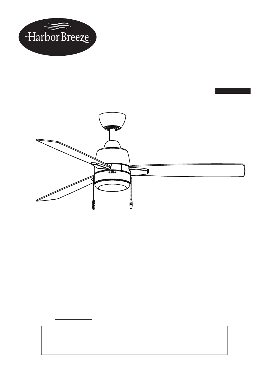
ARAMERE INDOOR
CEILING FAN
SG26183

2
TABLE OF CONTENTS
Package Contents ................................................................................................................................
Hardware Contents ..............................................................................................................................
Safety Information ................................................................................................................................
Preparation ...........................................................................................................................................
Initial Installation ....................................................................................................................................
Fan Installation .....................................................................................................................................
Wiring ...................................................................................................................................................
Final Installation....................................................................................................................................
Operating Instructions...........................................................................................................................
Care and Maintenance .......................................................................................................................
Troubleshooting ...................................................................................................................................
Limited Lifetime Warranty ....................................................................................................................
Replacement Parts List .......................................................................................................................
3
4
4
6
7
8
10
13
17
18
18
19
20
G
A
B
D
E
F
I
H
J
K
L
3
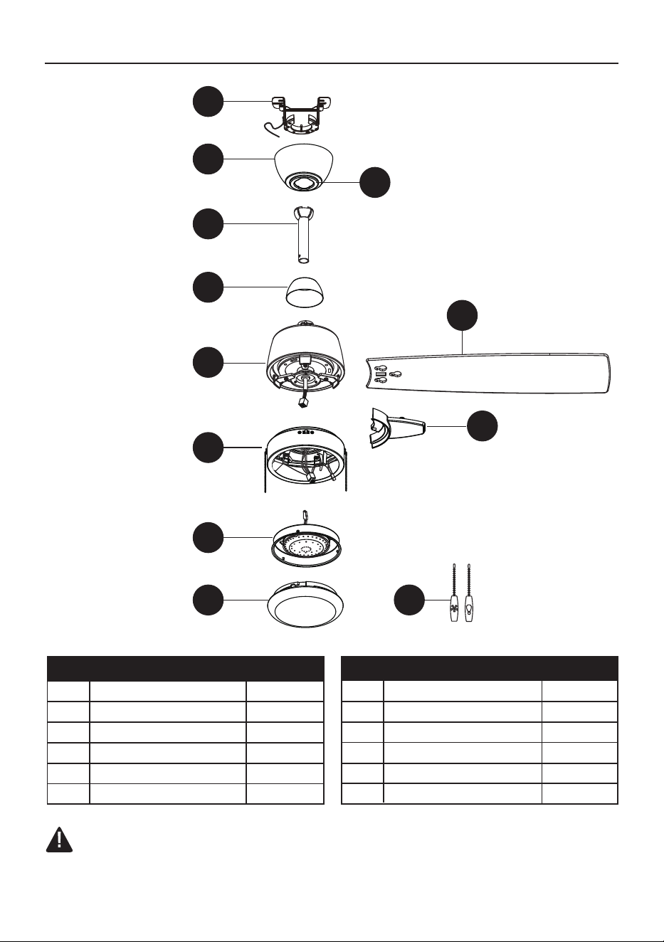
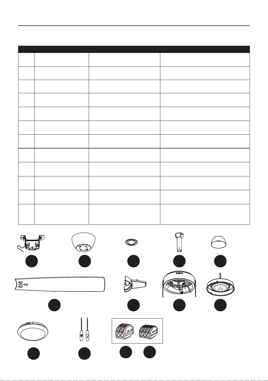
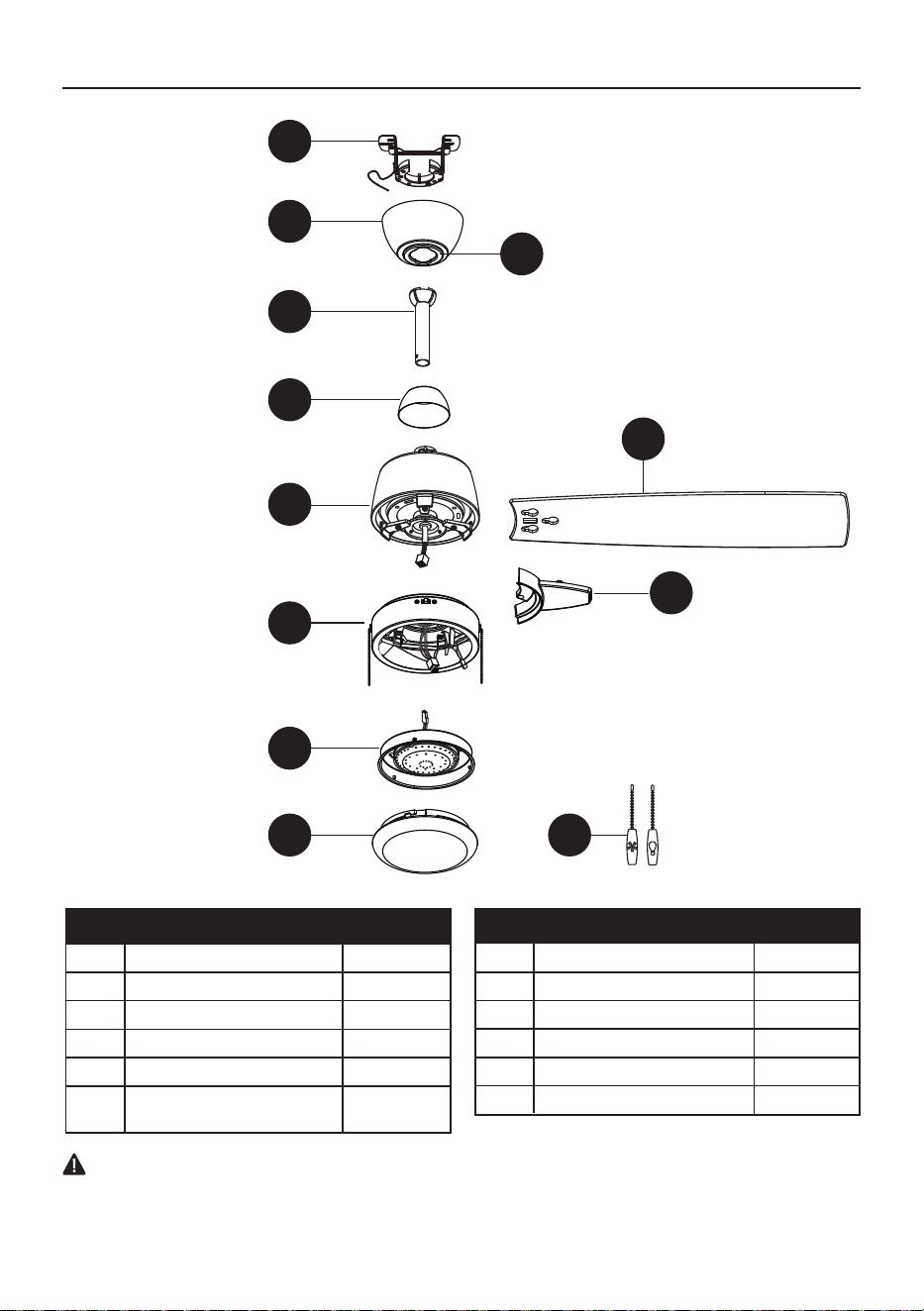
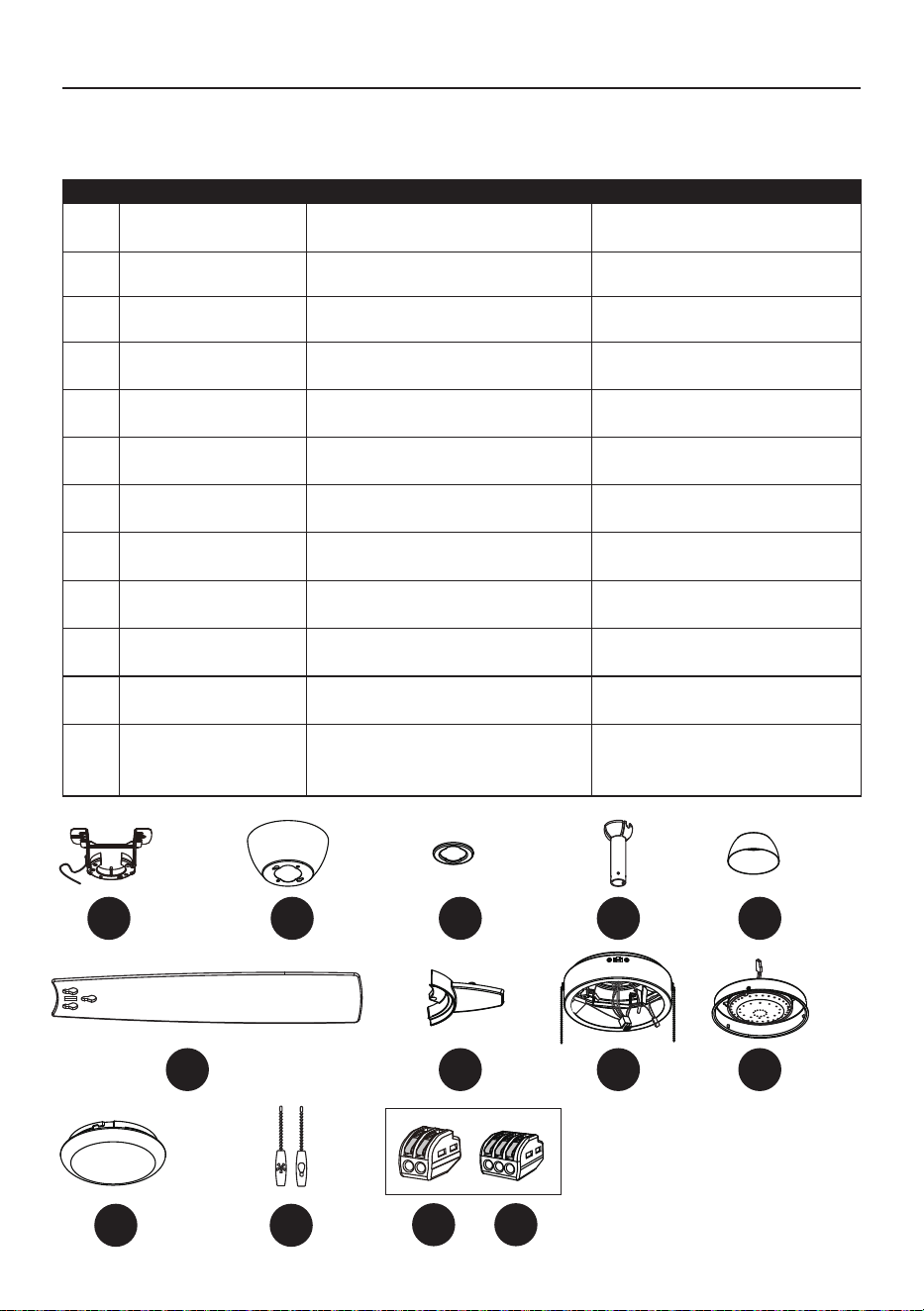
PACKAGE CONTENTS
IMPORTANT REMINDER: You must use
the parts provided with this fan for proper
installation and safety.
B
Canopy
D
Downrod
1
A Mounting Bracket 1
C Canopy Bottom Cover 1
E Coupling Cover
1
1
F Fan motor Assembly 1
DESCRIPTIONPART QUANTITY
3
3
G
Switch Housing
19W LED Light kit
I
J
K
L
H
1
1
1
2
DESCRIPTIONPART QUANTITY
Blade
Blade Arm
Pull chain and fob
Plastic shade
C
4
CAUTION: Changes or modifications not approved by the party responsible for compliance could void
the user's authority to operate the equipment.
*NOTE: This equipment has been tested and found to comply with the limits for a Class B digital
device, pursuant to Part 15 of the FCC Rules. These limits are designed to provide reasonable
protection against harmful interference in a residential installation. This equipment generates, uses
and can radiate radio frequency energy and, if not installed and used in accordance with the
instructions, may cause harmful interference to radio communications. However, there is no guarantee
that interference will not occur in a particular installation. If this equipment does cause harmful
interference to radio or television reception, which can be determined by turning the equipment off and
on, the user is encouraged to try to correct the interference by one or more of the following measures:
* Reorient or relocate the receiving antenna.
* Increase the separation between the equipment and receiver.
* Connect the equipment into an outlet on a circuit different from that to which the receiver is
connected.
Consult the dealer or an experienced radio/TV technician for help.
SAFETY INFORMATION
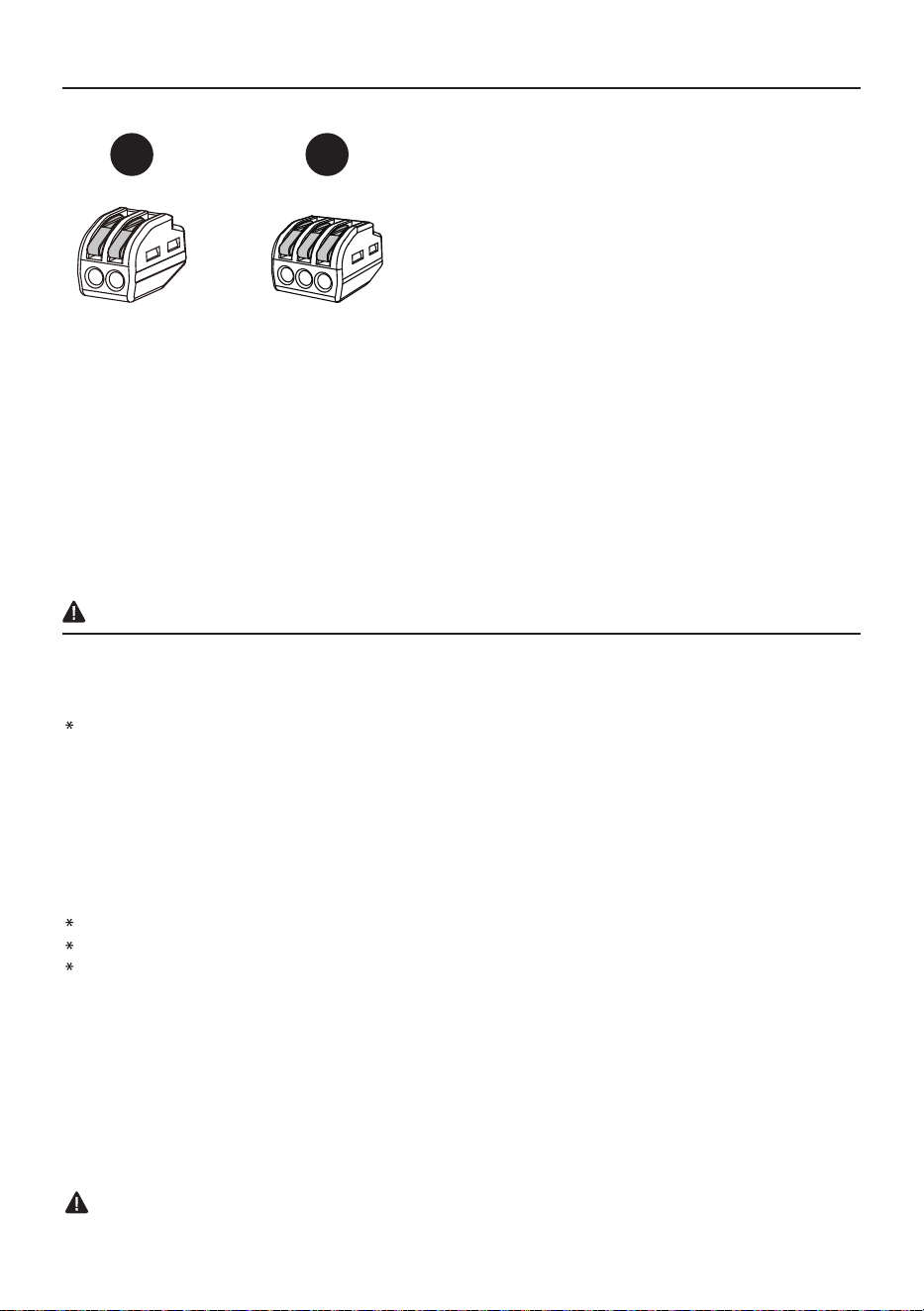
HARDWARE CONTENTS
The device complies with Part 15 of the FCC Rules. Operation is subject to the following two
conditions: (1) this device may not cause harmful interference, (2) this device must accept any
interference received, including interference that may cause undesired operation.
NOTE: Dimmable to 20% with select dimmers. See lowes.com for more information.
CAUTION: Changes or modifications not expressly approved by the party responsible for
compliance could void the user's authority to operate the equipment.
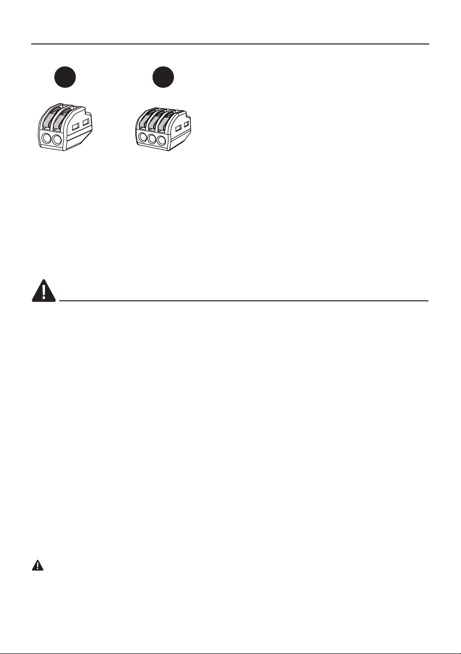
AA
BB
2-Wires
Connector
Qty. 1
3-Wires
Connector
Qty. 2
5
READ AND SAVE THESE INSTRUCTIONS
Please read and understand this entire manual before attempting to assemble, install or operate the
product.
• Do not discard fan carton or foam inserts. Should this fan need to be returned to the factory for repairs,
it must be shipped in its original packaging to ensure proper protection against damage that might
exceed the initial cause for return.
• Make sure all electrical connections comply with local codes, ordinances, the National Electrical Code
and ANSI/NFPA 70. Hire a qualified electrician or consult a do-it-yourself wiring handbook if you are
unfamiliar with installing electrical wiring.
• Make sure the installation site you choose allows a minimum clearance of 7 ft. from the blades to the
floor and at least 30 in. from the end of the blades to any obstruction.
• After you install the fan, make sure all connections are secure to prevent the fan from falling.
• The net weight of this fan including the light kit is:
SAFETY INFORMATION
WARNING
To reduce the risk of fire, electrical shock or personal injury, mount to an outlet box
UL-Listed acceptable for fan support of 35 lb. (15.9 kg) or less and use mounting screws
provided with the outlet box. Most outlet boxes commonly used for the support of lighting
fixtures are not acceptable for fan support and may need to be replaced. Consult a qualified
electrician if in doubt.
To reduce the risk of fire, electric shock or personal injury, mount the fan to the outlet box marked
acceptable for fan support with the screws provided with the outlet box.
NEED HELP? In the event you have broken glass or are missing parts, call 888-251-1003. Do
not return the ceiling fan to the place of purchase. Be sure to have available the owner's manual,
item or model number, finish, color, type of glass, etc.
Attention Statement needs to read this way.
ATTENTION: The use of a fan brace with all ceiling fans is recommended. Application style
vary. Braces are sold separately in the lighting or electrical department.
ATTENTION: Do not use an extension cord with this fan.
To reduce the risk of personal injury, use only parts provided with this fan. The use of parts
OTHER than those provided with this fan will void the warranty.
Before proceeding, be sure to shut off electricity at main switch or circuit breaker in order to
avoid electrical shock.
Risk of Fire and Electric Shock: Do not repair or service this light kit. The light source is designed
for this specific application and can overheat if serviced by untrained personnel. If any servicing
is required, call our customer service department (at 888-251-1003) for return authorization and
shipping instructions.
AR73B-42: 11.42 lbs
AR73B-52: 12.72 lbs.
6
SAFETY INFORMATION
CAUTION
To reduce the risk of personal injury, use only the screws provided with the outlet box.
Be sure outlet box is properly grounded and that a ground wire (green or bare) is present.
Before beginning installation, carefully check all screws, bolts and nuts on fan motor assembly to
ensure that they are secured.
Before beginning assembly of product, make sure all parts are present. Compare parts with package
contents list and hardware contents list. If any part is missing or damaged, do not attempt to assemble
the product.
Estimated Assembly Time: 120 minutes.
Tools Required for Assembly (not included): Electrical Tape, Phillips Screwdriver, Pliers, Safety
Glasses, Stepladder and Wire Strippers.
Helpful Tools (not included): AC Tester Light, Tape Measure, Do-It-Yourself Wiring Handbook and
Wire Cutters.
DANGER: When using an existing outlet box, make sure the outlet box is securely attached to the
building structure and can support the full weight of the fan. Failure to do this can result in serious
injury or death. The stability of the outlet box is essential in minimizing wobble and noise in the fan
after installation is complete.
CAUTION: Be sure outlet box is properly grounded and a ground wire (green or bare) is present.
After opening top of carton, remove mounting hardware package from foam inserts. Remove motor
from packing and place on carpet or on foam to avoid damage to finish.
CAUTION: Carefully check all screws, bolts and nuts on fan motor assembly to ensure they are
secured.
PREPARATION
7
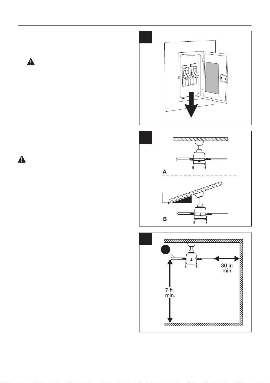
1. WARNING: Turn off circuit breakers and wall
switch to the fan supply line leads.
2. Determine mounting method to use.
A. Standard mount
B. Angle mount
IMPORTANT: If using angled mounting,
ensure the ceiling angle for AR73B-42" fan is not
steeper than 23° and for AR73B-52" fan it is not
steeper than 21°.
*Helpful Hint: Standard mounting is best suited
for ceilings 7 ft. high or higher. For taller ceilings
you may want to use a longer downrod (not
included). Angle mounting is best suited for angled
or vaulted ceilings. A longer downrod is sometimes
necessary to ensure proper blade clearance.
3. Check to make sure blades (G) will be at
least 30 in. from any obstruction and at least
7 ft. above the floor.
DANGER: Failure to disconnect power
supply prior to installation may result in
serious injury or death.
1
ON
OFF
ON
OFF
3
2
INITIAL INSTALLATION
6
G
AR73B-42”-23° max.
AR73B-52”-21° max.
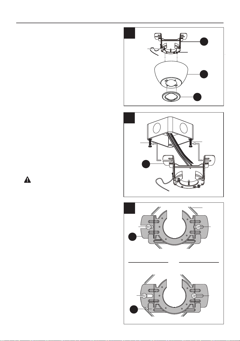
Attach the mounting bracket (A) on the outlet
box by sliding the mounting bracket (A) over
the screws provided with the outlet box. Note
that the flat side of the mounting bracket (A) is
toward the outlet box.
Securely tighten the two mounting screws.
*NOTE: It is very important you use the proper
hardware when installing the mounting bracket
(A) as this will support the fan.
IMPORTANT: If using the angle mount,
make sure open end of mounting bracket (A) is
installed facing the higher point of the ceiling.
8
1
Outlet Box
Screws
Remove the canopy bottom cover (C) from
the canopy (B) by turning the canopy bottom
cover (C) counterclockwise.
Remove the mounting bracket (A) from the
canopy (B) by loosening canopy mounting
screws a half turn from the screw head. Next,
turn the canopy (B) counterclockwise to
remove the mounting bracket (A) from the
canopy (B).
1.
2A.
2B.
FAN INSTALLATION
A
B
C
Canopy
Mounting
Screw
Canopy
Mounting
Screw
Provide an image of the slide on mounting
bracket (A) correct screw position.
Outlet Box
Screws
2A
2B
A
Outlet Box
CORRECT Screw POSITION
A
Screw
Screw
Screw
Position
Screw
Position
VS
INCORRECT Screw POSITION
(view from
underside)
A
(view from
underside)
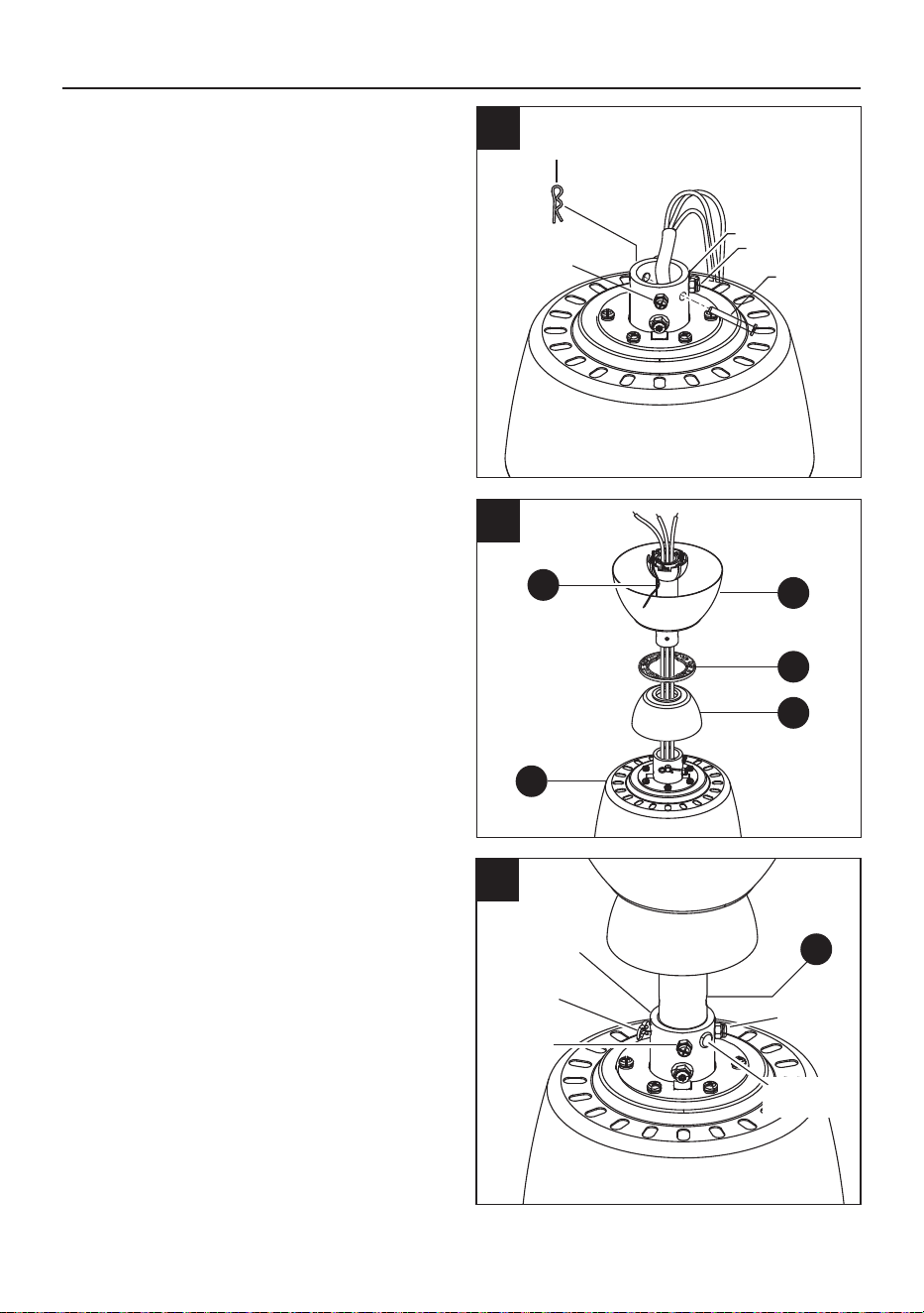
9
Set Screw
Set Screw
Collar
Cotter Pin
D
Clevis Pin
5
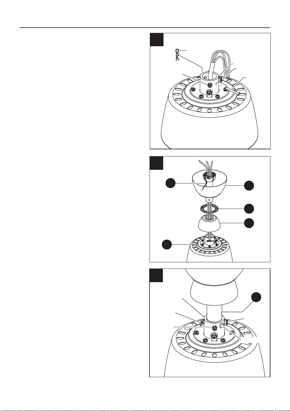
Insert downrod (D) through canopy (B),
canopy bottom cover (C) and coupling cover
(E). Thread wires from fan motor assembly
(F) up through downrod (D).
4.
Slip downrod (D) into collar, align holes and
re-install clevis pin and cotter pin. Tighten set
screws in collar.
5.
FAN INSTALLATION
4
F
C
E
B
D
3. Remove the cotter pin and clevis pin, and
loosen the two collar set screws from the fan
motor assembly collar.
Cotter
Pin
Set Screw
Collar
Set Screw
Clevis pin
3
A
10
6
Carefully lift the fan motor assembly (F) up to
the mounting bracket (A) and seat the downrod
(D) in the mounting bracket (A) socket. Make
sure the tab on the mounting bracket (A)
socket is properly seated in the groove in the
downrod (D). This will help to balance the
ceiling fan.
6.
DANGER: Failure to align slot in ball with
tab may cause the fan to wobble or fall, which
could result in serious injury or death.
FAN INSTALLATION
F
D
Tab
8 in.
Slot
WIRING
WARNING: To reduce the risk of fire, electrical shock or personal injury, wire connectors
provided with this fan are designed to accept only one 12-gauge house wire and two lead wires
from the fan. If your house wire is larger than 12-gauge or there is more than one house wire to
connect to the two fan lead wires, consult an electrician for the proper size wire connectors to use.
WARNING: If house wires are different colors than referred to in the following steps, stop
immediately. A professional electrician is recommended to determine wiring.
NOTE: This fan is remote control adaptable (remote control not included). If you choose to
purchase a remote control for use with the fan, be advised that the dimming function for the light
will not be operable. Dimming capability for this light is only possible by using wall controls that
control the fan and light separately, such as the WM-7WWL (not included).
CAUTION: Be sure outlet box is properly grounded and a ground (green or bare) wire is present.
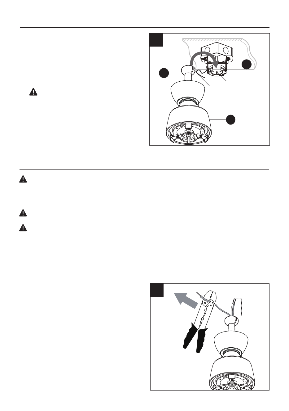
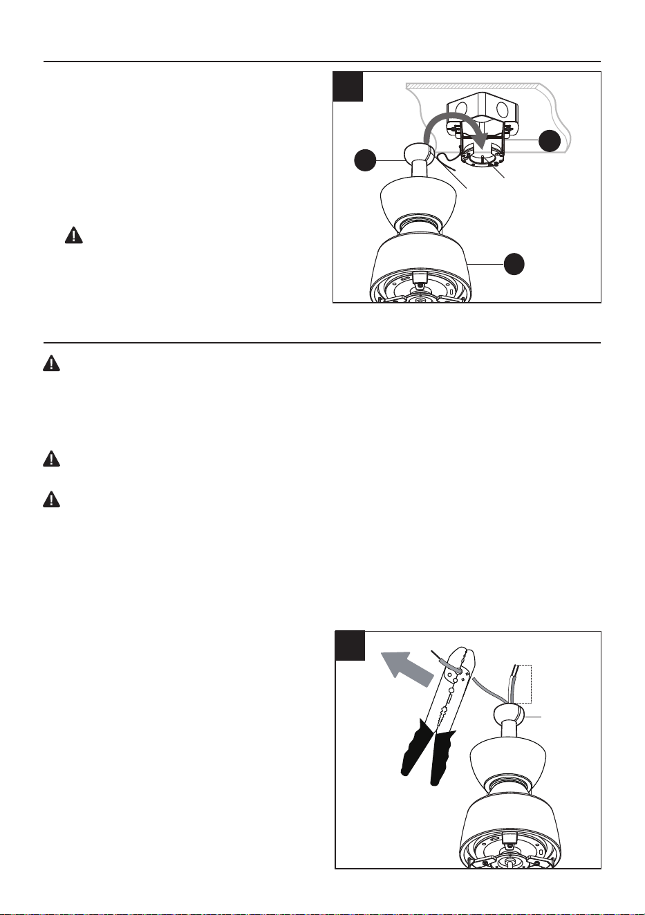
Depending on the length of downrod you
use, you may need to cut the lead wires
back to simplify the wiring. If you decide to
cut back the lead wires, it is suggested you
do so in the following manner:
Take the lead wires and make sure you have
pulled them all the way through the top of
the downrod. Start at the TOP of the ball on
the downrod and measure 8 in. of lead wire,
and then cut the excess wire off with wire
cutters (not included).
1A.
Hanger
Ball
1A
11
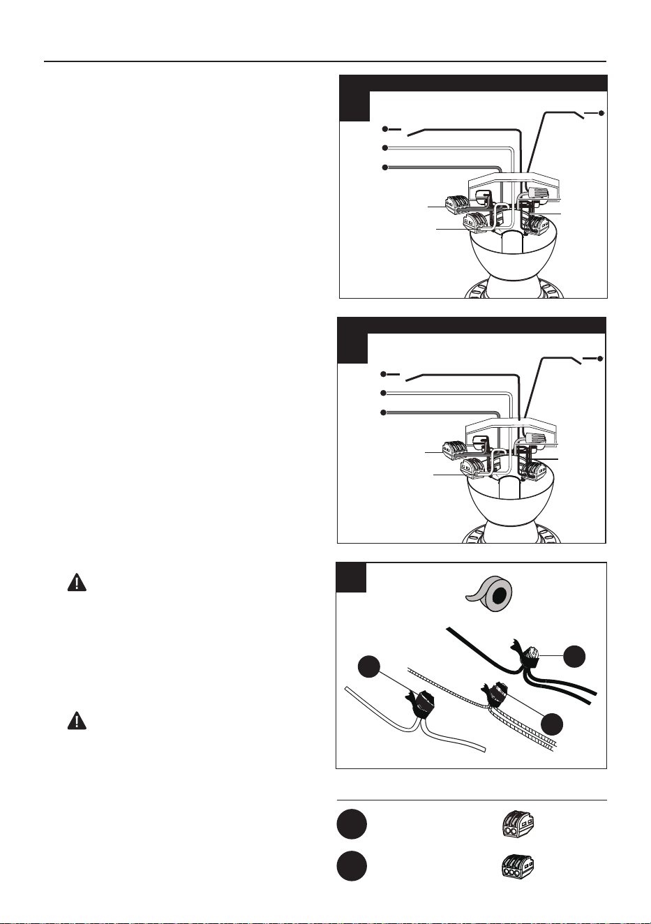
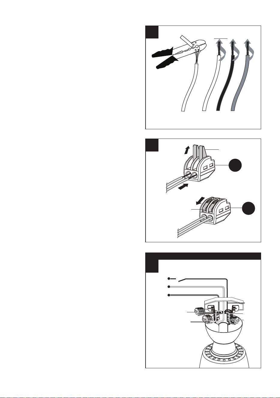
Choose wiring diagram (Fig. 3A, Fig. 3B or
Fig. 3C) that fits your situation and make
appropriate wiring connections as follows:
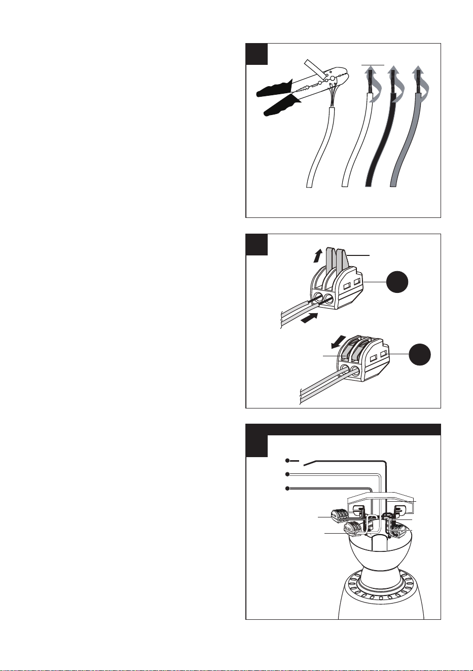
3A. FAN AND LIGHT CONTROLLED BY
PULL CHAINS: Connect BLACK and BLUE
wire from fan to BLACK wire from ceiling.
Connect WHITE wire from fan to WHITE
wire from ceiling. Connect all GROUND
(GREEN) wires together from fan (on
downrod (D) and mounting bracket (A) to
BARE/GREEN wire from ceiling.
3.
NOTE: If you do not cut back the lead wires,
Steps 1A and 1B are not necessary and
you may proceed to Step 2 instead.
If you decided to cut back the lead wires in
Step 1A, strip a 1/2 in. of insulation from end
of white wire. Twist stripped ends of each
strand of wire within the insulation with pliers
(not included). Repeat Step 1B for black,
blue (if applicable) and green wires.
1B.
This ceiling fan comes with two types of
connectors: 2-wires connector (AA) and
3-wires connector (BB). Please select the
appropriate connector for your wiring needs.
WIRE CONNECTOR WIRING: Push the retaining
handle on the connector upwards first,, and
then push the wire into the connection hole
and press the retaining handle downwards to
secure the wire.
2.
Wires
Fixed Handle
Fixed Handle
Wires
2
AA
AA
1B
3A
FAN AND LIGHT CONTROLLED BY PULL CHAINS
120v Power
From Ceiling
Black (power)
White (neutral)
Ground/green (bare)
Black
Green
White
Blue
Black
DOWN
UP
IN
12
Hardware Used
3-Wires Connector x2
2-Wires Connector x1
AA
BB
WIRING
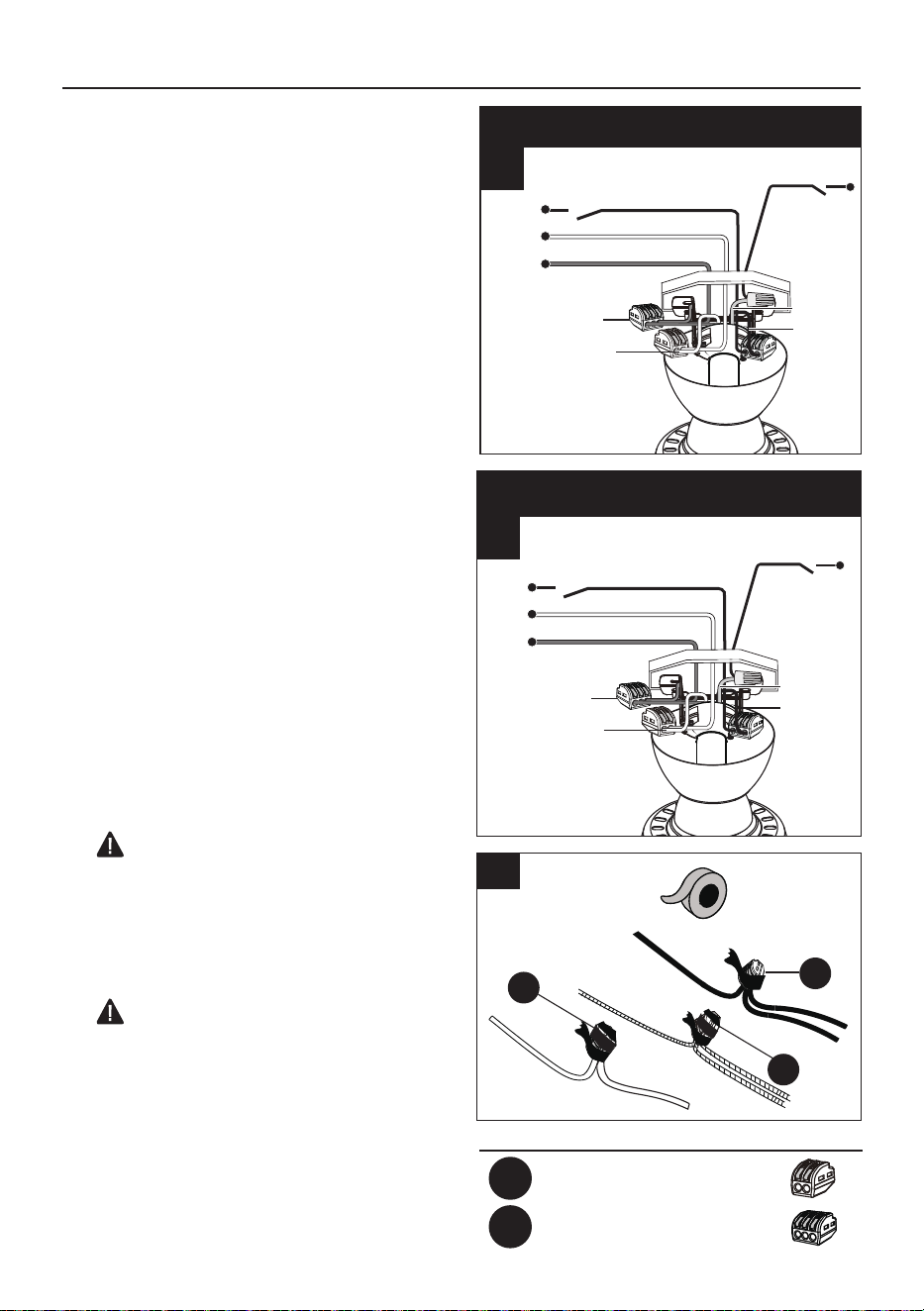
3B. FAN CONTROLLED BY PULL CHAIN,
LIGHT BY WALL SWITCH: If you intend to
control the fan light with a separate wall
switch, connect BLACK wire from fan to
BLACK wire from ceiling. Connect BLUE wire
from fan to the BLACK wire from the
independent wall switch for the light. Connect
WHITE wire from fan to WHITE wire from
ceiling with wire nut (not included). Connect
all GROUND (GREEN) wires together from
fan (on downrod (D) and mounting bracket
(A)) to BARE/GREEN wire from ceiling.
3C. FAN AND LIGHT CONTROLLED BY
TWO WALL SWITCHES: If you intend to
control the fan and light with separate wall
switches, connect BLACK wire from fan to
BLACK wire from the independent wall
switch for the fan. Connect BLUE wire from
fan to the BLACK wire from the other
independent wall switch for the light. Connect
WHITE wire from fan to WHITE wire from
ceiling with wire nut (not included). Connect
all GROUND (GREEN) wires together from
fan (on downrod (D) and mounting bracket
(A)) to BARE/GREEN wire from ceiling.
NOTE: BLACK wire is hot power for fan.
BLUE wire is hot power for light kit. WHITE
wire is common for fan and light kit. BARE/
GREEN wire is ground.
4. Wrap electrical tape (not included) around
each individual wire connectors (AA & BB)
down to the wire.
Turn spliced/taped wires upward and gently
push wires and wire connectors (AA & BB)
into outlet box.
WARNING: Make sure no bare wire or
wire strands are visible after making
connections. Place GREEN and WHITE
connections on opposite side of box from the
BLACK and BLUE (if applicable) connections.
WARNING: If you use a wall switch to
dim a light fixture, DO NOT use a pull chain
simultaneously. This will damage the light
fixture.
4
BB
BB
AA
F
H
Screws
Screws
Remove the
rubber packing
mounts
3B
FAN CONTROLLED BY PULL CHAIN, LIGHT BY WALL SWITCH
120v Power
From Ceiling
Black (power)
White (neutral)
Ground/green (bare)
Green
White
Blue
Black
(wall switch
for light)
Black
3C
FAN AND LIGHT CONTROLLED BY TWO WALL SWITCHES
120v Power
From Ceiling
Black (wall switch)
White (neutral)
Ground/green (bare)
Green
White
Blue
Black
(wall switch
for light)
Black
13
WIRING
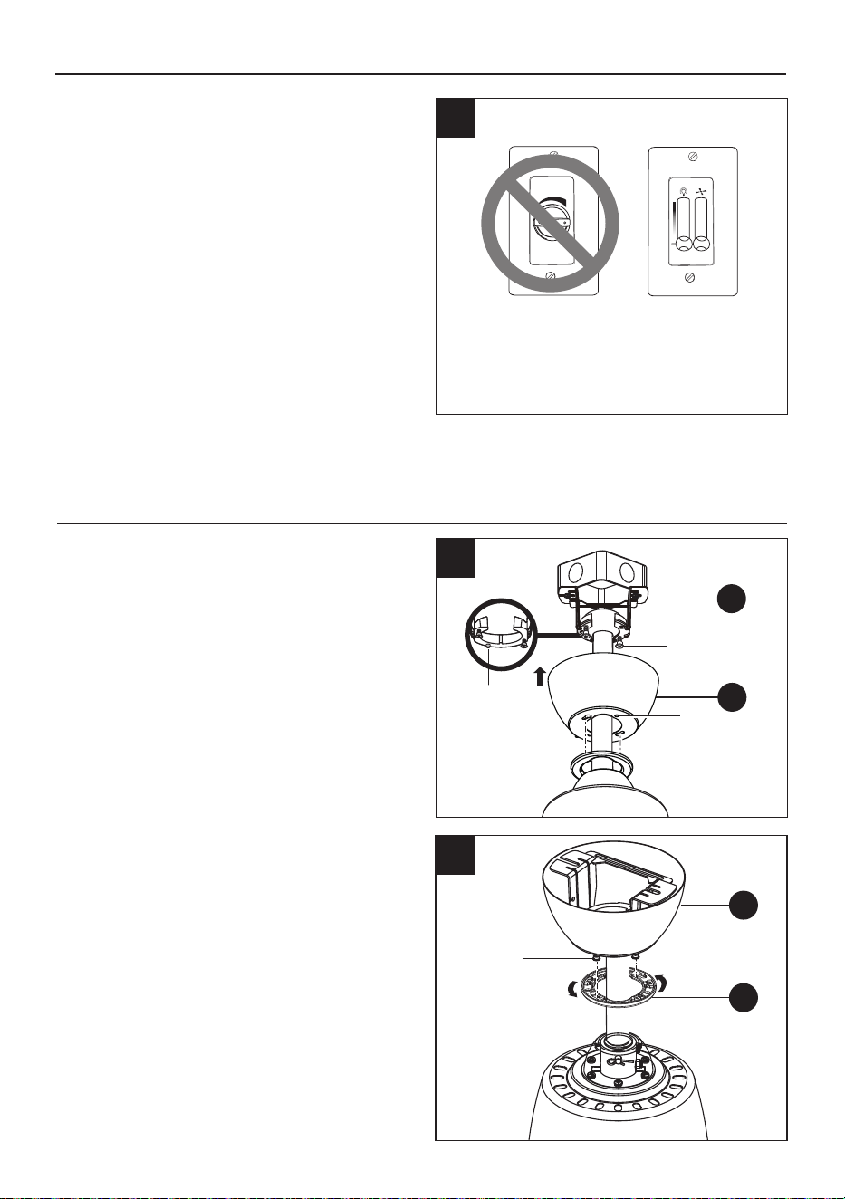
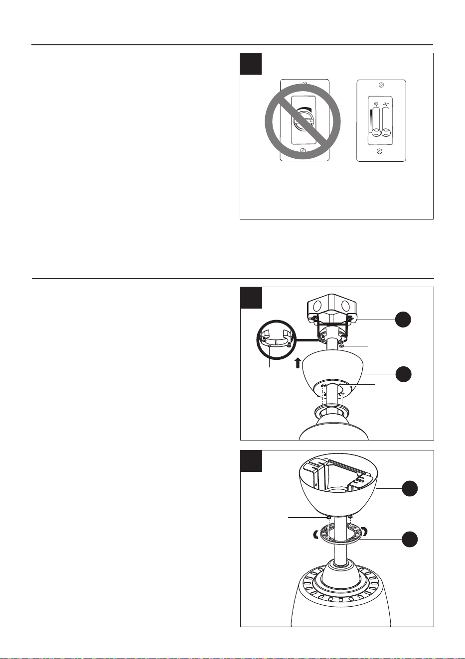
5. IMPORTANT: Using a full range dimmer
switch (not included) to control fan speed will
cause a loud humming noise from fan. To
reduce the risk of fire or electrical shock, do
NOT use a full range dimmer switch to
control fan speed.
5
Dimmer
Switch
Speed
Switch
For illustrative purposes only - not
intended to cover all types of controls.
1
2
3
Make sure connections are neatly tucked into
the ceiling outlet box.
Slide the canopy (B) up to the mounting
bracket (A) and place the key holes on the
canopy (B) over the loose canopy mounting
screws on the mounting bracket (A). Turn the
canopy (B) clockwise until it locks in place at
the narrow section of the key holes. Make
sure the positioning pin on the mounting
bracket (A) falls into one of two holes on the
canopy (B), and then tighten the two canopy
mounting screws.
1.
Attach the canopy bottom cover (C) to the
canopy (B) by inserting the screw heads into
the key slots in the canopy bottom cover (C)
and rotating it clockwise.
NOTE: Adjust the canopy mounting screws
as necessary until the canopy (B) and canopy
bottom cover (C) are snug.
2.
FINAL INSTALLATION
2
1
Positioning
Pin
B
A
Canopy Mounting
Screw
Canopy
Mounting
Screw
B
C
Hole
F
I
Wire Connectors
Mounting
screws
Switch Housing
Mounting Ring
14
3.
FINAL INSTALLATION
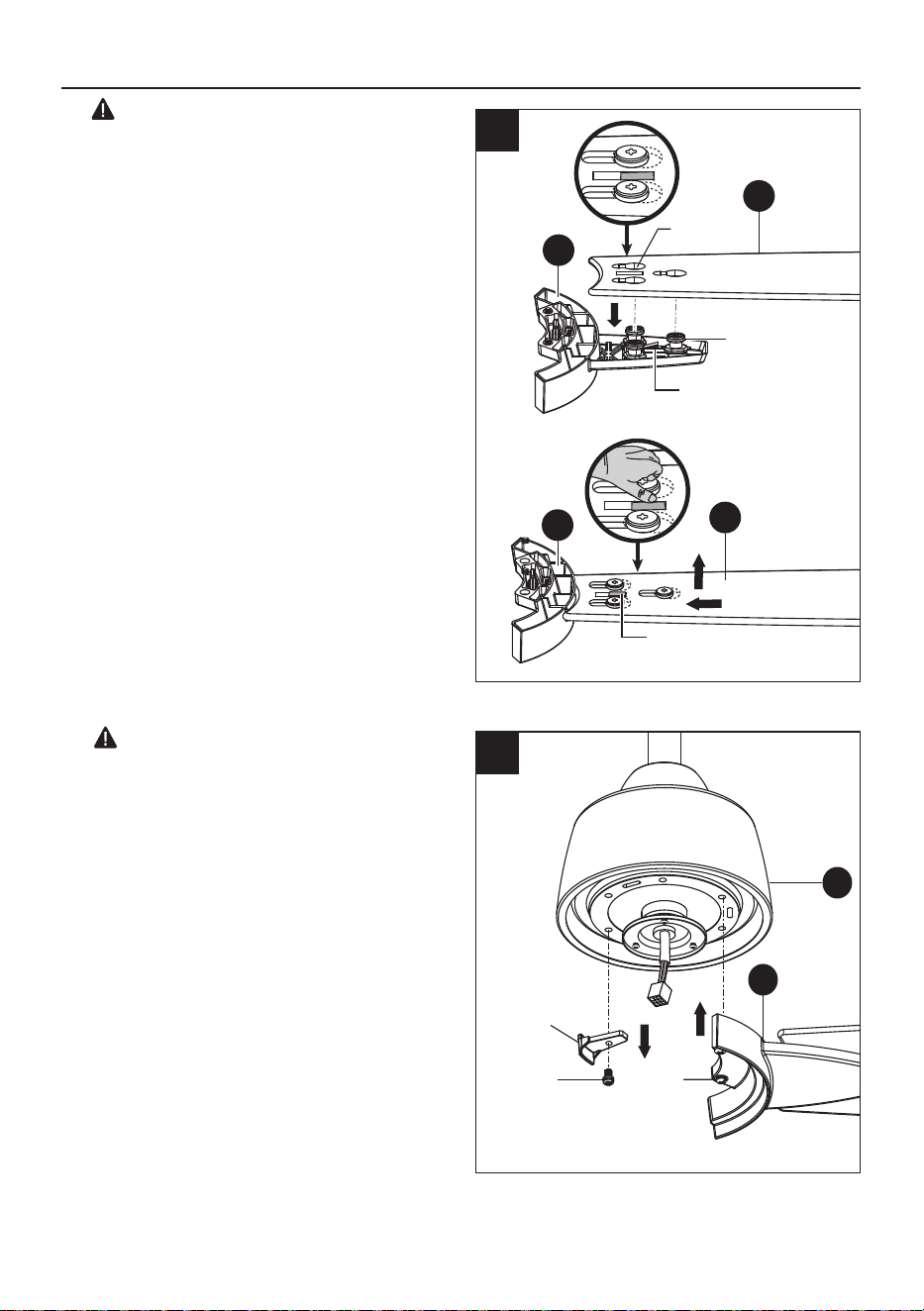
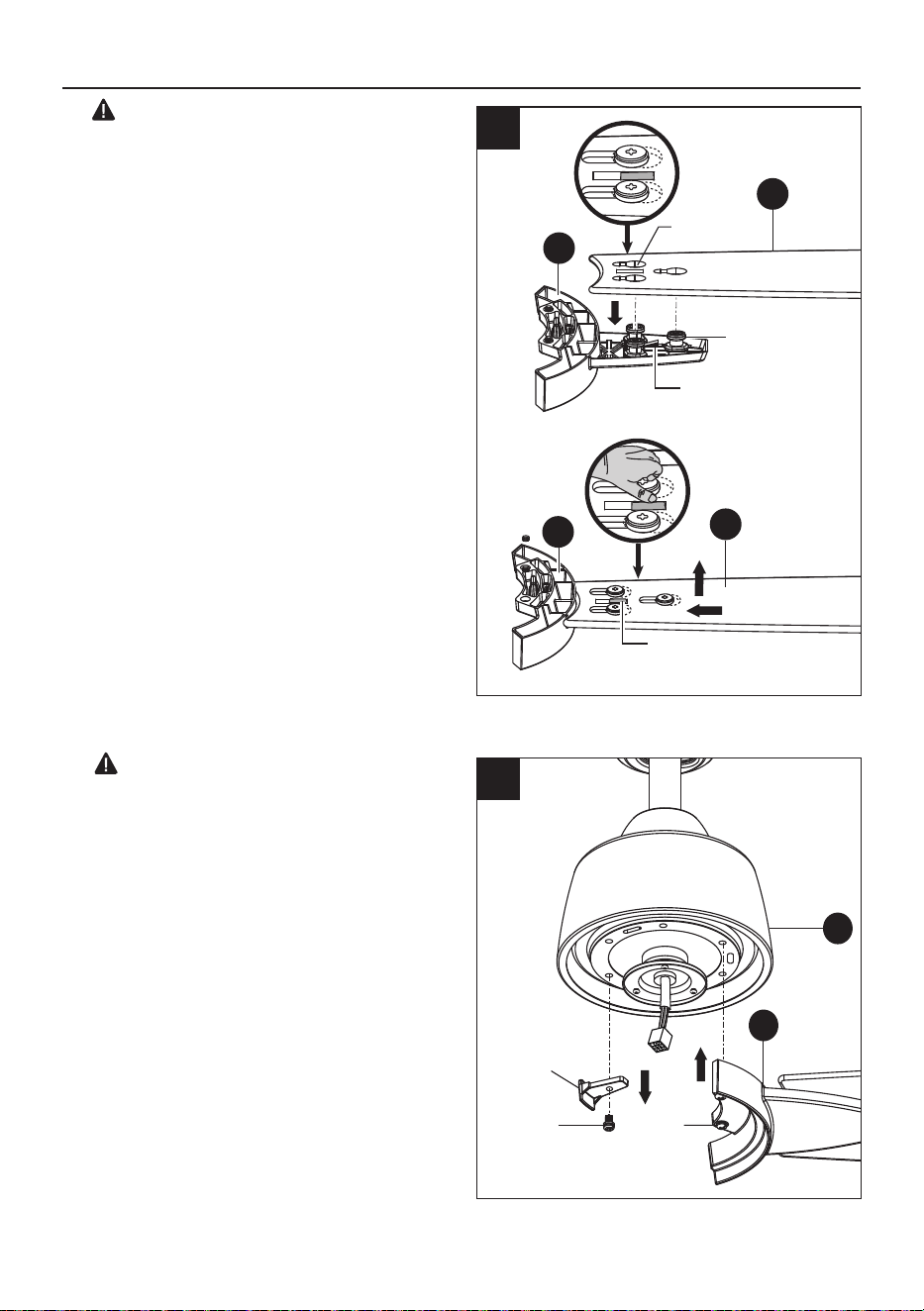
WARNING: Failure to properly seat the
blades (G) on the blade arms (H) and engage
in the spring locking mechanism could result
in the fan blades (G) loosening and possibly
falling.
Hold the blade (G) with hands close to the
blade arm (H), align the key-slot holes with
the blade arm posts and press the blade
down firmly. Ensure the key-slot holes are
properly seated on the blade arm posts.
Firmly slide the blade (G) away from the
blade arm (H) until the blade (G) engages in
the spring locking mechanism. Make sure the
spring of the spring locking mechanism is
upward and the butt of the spring locking
mechanism is against the edge of the blade.
3
Blade Arm
Posts
G
H
Key-slot
Holes
Spring Locking
Mechanism
H
G
Spring Locking
Mechanism
To detach the blade (G) from the blade arm (H) :
Press down the spring locking mechanism
to release the blade (G) from the blade arm
(H). Slide the blade (G) toward the blade
arm (H) until the blade (G) disengages from
the spring locking mechanism, carefully
push the blade (G) up to detach from the
blade arm (H).
Screws
Remove the
rubber packing
mounts
Screws
4.
WARNING: To reduce the risk of personal
injury, do not insert foreign objects between
rotating fan blades (G).
Fasten the blade arm (H) to the fan motor
assembly (F) by lining up the holes of the
blade arms (H) and the fan motor assembly (F).
Tighten the two blade arm screws with lock
washers already installed in the blade arms
(H). Repeat this procedure for the remaining
blade arm (H).
4
F
H
15
FINAL INSTALLATION
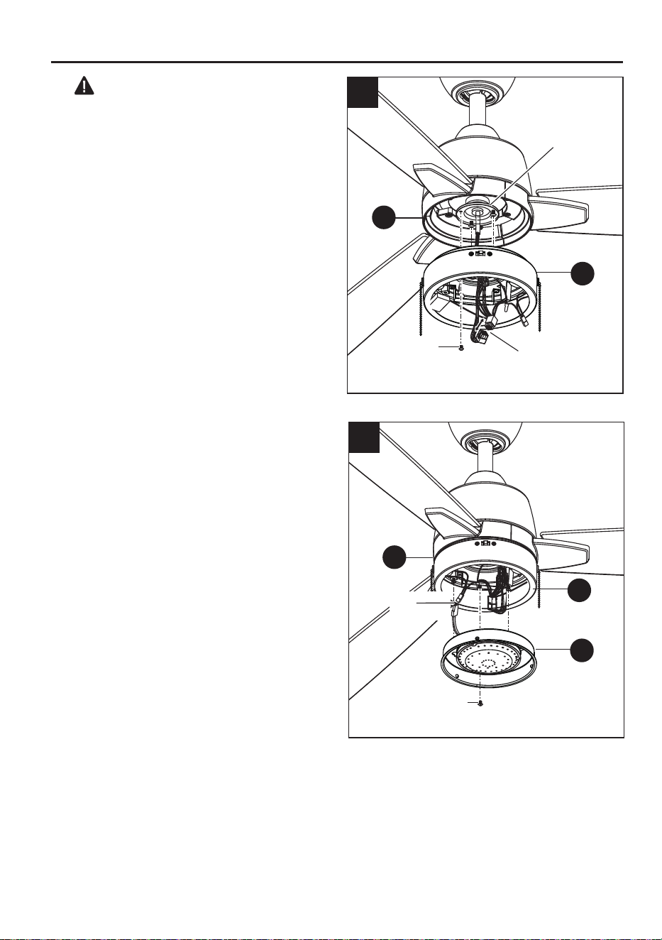
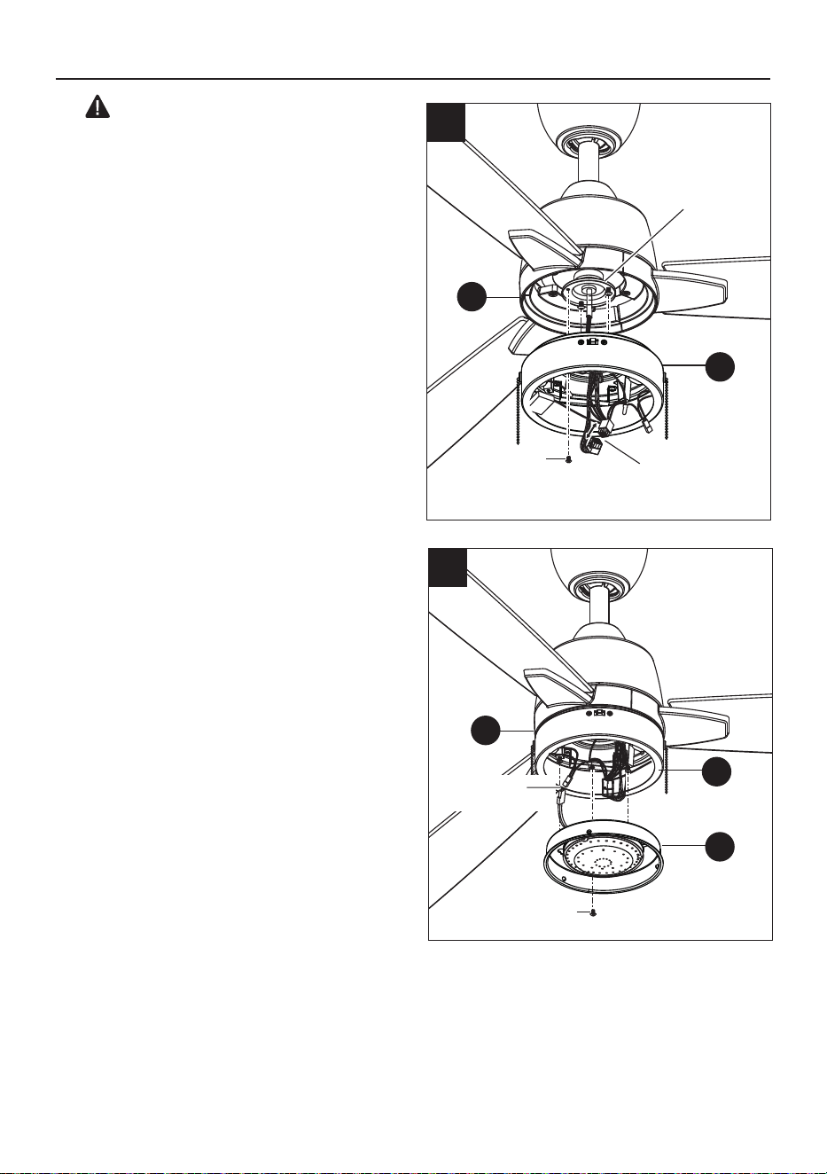
Reinstall the two switch housing mounting
screws that were just removed back to the
switch housing mounting ring. (Do not tighten.)
While holding the switch housing (I) under the
fan motor assembly (F), snap together the
wire connection plug with the 9-pin plug from
the switch housing (I).
Place the key holes on the switch housing (I)
over the two screws previously loosened
from the mounting ring. Turn the switch
housing (I) until it locks in place at the narrow
section of the key holes. Secure by tightening
the two mounting screws previously loosened
and the one previously removed.
5.
CAUTION: Before starting installation,
disconnect the power by turning off the circuit
breaker or removing the fuse at the fuse box.
Turning power off using the fan switch is not
sufficient to prevent electric shock.
5
Mounting
screws
Wire Connectors
Switch Housing
Mounting Ring
Remove one of the three light kit mounting
screws from the switch housing (I) and loosen
the other two light kit mounting screws. (Do
not remove.)
While holding the 19W LED light kit (J) under
the fan motor assembly (F), make the 2-pin
wire connections.
Place the key holes on the 19W LED light kit
(J) over the two mounting screws previously
loosened from the switch housing (I). Turn
the 19W LED light kit (J) until it locks in place
at the narrow section of the key holes. Secure
by tightening the two light kit mounting
screws previously loosened and the one
previously removed.
6.
F
J
I
Mounting
screws
Wire
Connectors
6
F
I
16
FINAL INSTALLATION
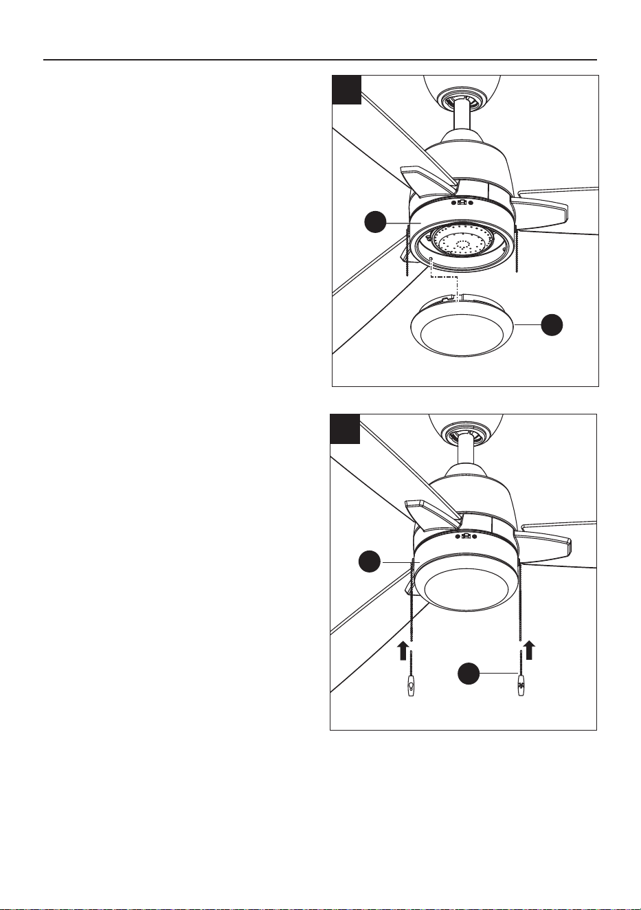
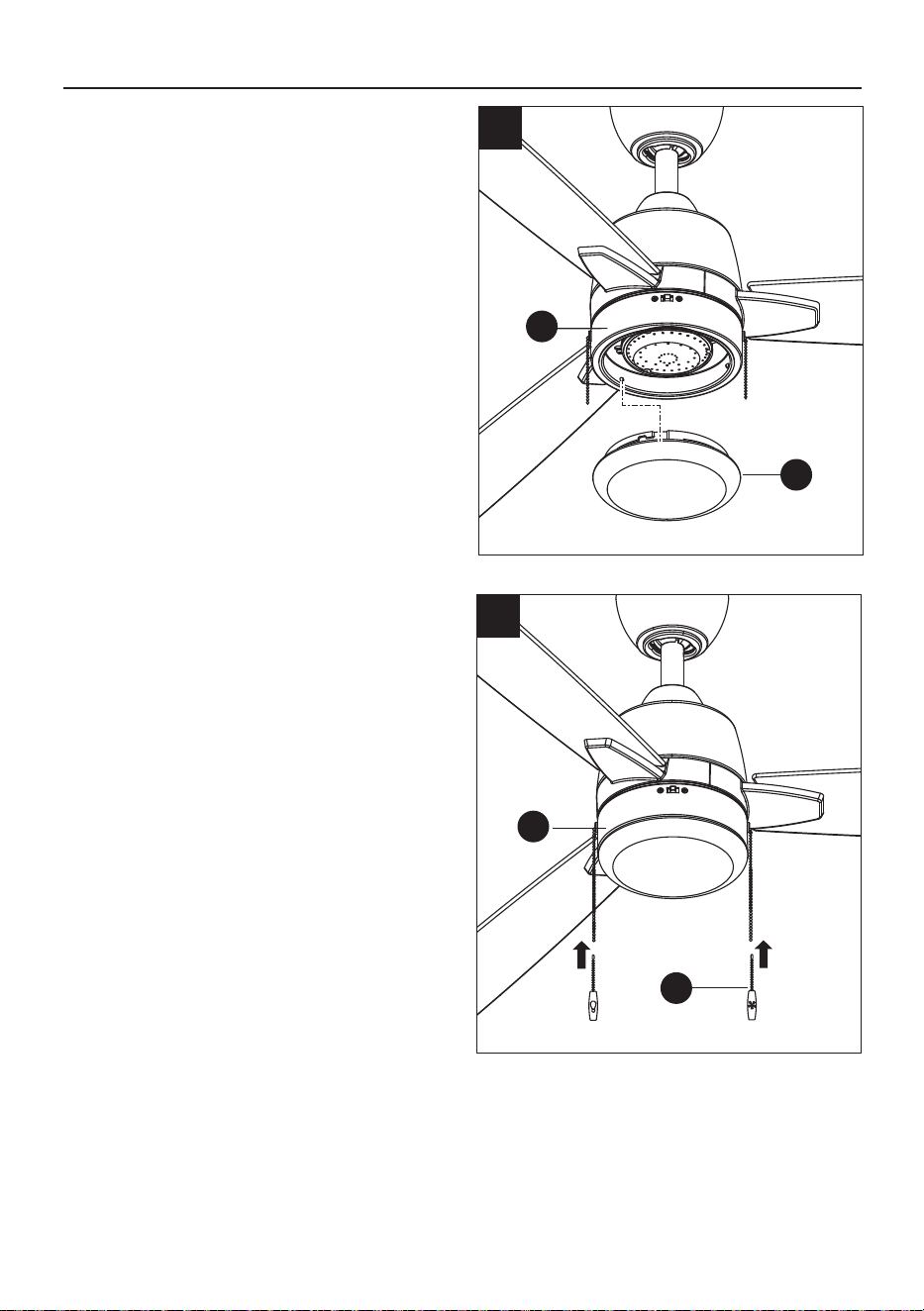
7.
Raise the plastic shade (K) up against the
19W LED light kit (J) and secure it to the fan
by turning the plastic shade (K) clockwise
until snug. DO NOT OVERTIGHTEN.
K
J
7
Install the pull chains and fobs (L) onto the
pull chains located in the switch housing (I).
8.
I
L
8
17
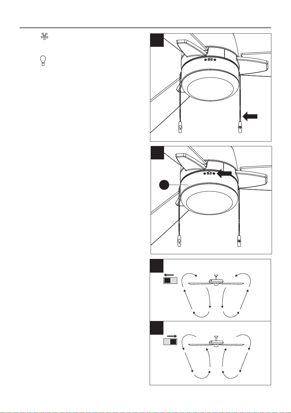
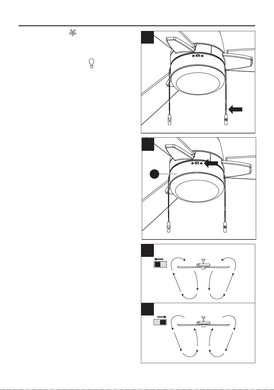
OPERATING INSTRUCTIONS
The pull chain controls the fan speed as
follows: 1 pull - High, 2 pulls - Medium,
3 pulls - Low, 4 pulls - Off.
The light pull chain controls the light kit:
"ON" and "OFF" or "DIMMABLE". Pull down
and release immediately to control the light to
turn it on or off. Pull down and hold; the
brightness will continually increase or
decrease. The light kit retains its previous
brightness setting after being turned off.
1.
2.
The reverse switch is located on the surface
of the switch housing (I). Slide the switch to
the left for warm weather operation. Slide the
switch to the right for cool weather operation.
NOTE: Wait for the fan to stop before
reversing the direction of the blade rotation.
3A. Warm weather - (Counter-clockwise Direction)
A downward air flow creates a cooling effect.
This allows you to set your air conditioner on
a warmer setting without affecting your comfort.
3B. Cool weather - (Clockwise Direction) An
upward air flow moves warm air off the ceiling.
This allows you to set your heating unit on a
cooler setting without affecting your comfort.
2
3A
3B
I
1
CAUTION: When installing the wall switch or
remote control, be sure your fan pull chain
switch are in the "HIGH SPEED" position, and
pull down and hold light to the BRIGHTEST
position, then you can use a wall switch to
dim a light fixture
18
Check the support connections, brackets, and blade attachments twice a year. Make sure they are
secure. Because of the fan’s natural movement, some connections may become loose over time. It is
not necessary to remove the fan from the ceiling. Clean your fan periodically. Use only a soft brush or
lint-free cloth to avoid scratching the finish. The plating is sealed with a lacquer to minimize discoloration
or tarnishing.
IMPORTANT: Shut off main power supply before beginning any maintenance. Do not use water or
a damp cloth to clean the ceiling fan.
CARE AND MAINTENANCE
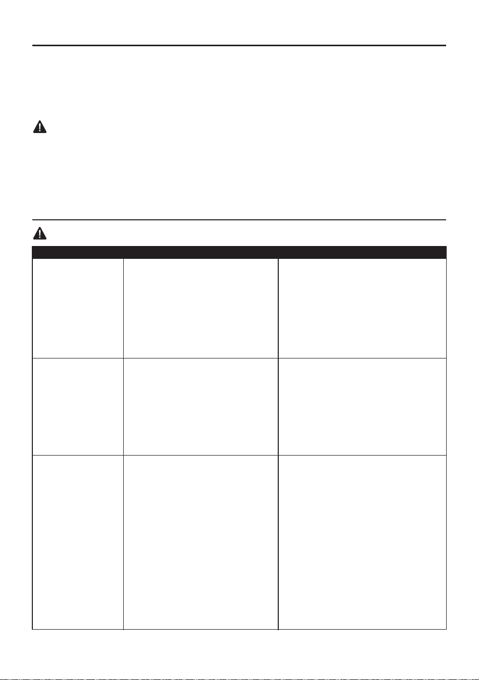
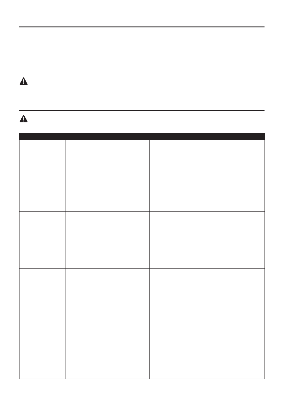
TROUBLESHOOTING
PROBLEM POSSIBLE CAUSE CORRECTIVE ACTION
Fan does not move.
1. Reverse switch not engaged.
2. Power is off or fuse is blown.
3. Faulty wire connection.
4. Plugs not connected properly.
1. Push switch firmly either left or right.
2. Turn power on or check fuse.
3. Turn power off. Loosen canopy and
check all connections.
4. Check that wire connectors in switch
housing are connected properly
according to instructions on page
15.
Noisy operation.
1. Blades are loose.
2. Cracked blade.
3. Full range dimmer switch.
4. Fan is new, motor need break in.
1. Blade arms incorrectly attached.
2. Unbalanced blades.
3. Fan not securely mounted.
4. Fan too close to vaulted ceiling.
5. Set screw(s) on motor housing
yoke is (are) not tightened
properly.
6. Set screw on hanging ball is not
tightened properly.
1. Tighten all blade screws.
2. Replace blade.
3. Replace with an approved speed
control device.
4. Allow fan a “break in” period of a few
days, especially when running the
fan at Medium and High speeds.
Excessive wobbling.
1. Re-install blade arms.
2. Switch one blade with a blade from
the opposite side. Or balance the
fan using a blade balancing kit (sold
separately).
3. Turn power off. Carefully loosen
canopy and verify that mounting
bracket is secure.
4. Use a longer downrod or move fan
to another location.
5. Tighten yoke set screw(s) securely.
6. Carefully loosen and lower canopy
and verify that set screw on hanging
ball is tightened securely.
WARNING: Before beginning work, shut off the power supply to avoid electrical shock.
19
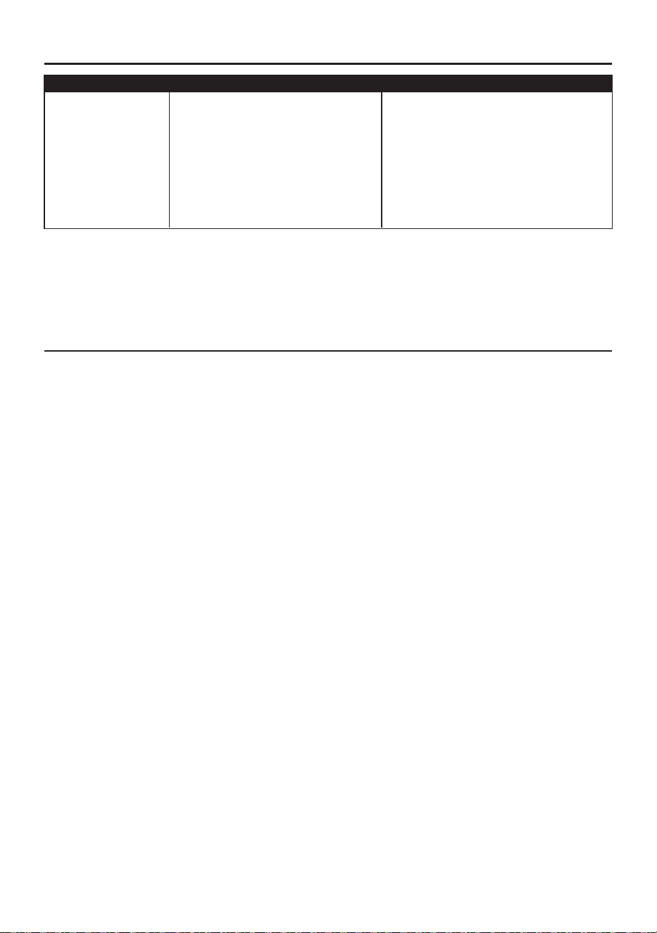
NOTE: A small amount of "wobble" is normal and should not be considered a defect.
TROUBLESHOOTING
PROBLEM POSSIBLE CAUSE CORRECTIVE ACTION
Fan operates but
light fails.
1. Wires in canopy not wired properly.
2. Wall switch to fan is off.
3. Plugs not connected properly.
1. Check wires in canopy and, if
necessary, re-wire according to
instructions on pages 11 and 12.
2. Make sure that wall switch to fan is on.
3. Check that wire connectors in
switch housing are connected
properly according to instructions on
page 15.
The distributor warrants this fan to be free from defects in workmanship and materials present at time
of shipment from the factory for Lifetime limited from the date of purchase. This warranty applies only
to the original purchaser. The distributor agrees to correct any defect at no charge or, at our option,
replace the ceiling fan with a comparable or superior model.
To obtain warranty service, present a copy of your sales receipt as proof of purchase. All cost of
removal and reinstallation are the express responsibility of the purchaser. Any damage to the ceiling
fan by accident, misuse or improper installation, or by using parts not produced by the manufacturer of
this fan or affixing accessories not produced by the manufacturer of this fan, are the purchaser's own
responsibility. The distributor assumes no responsibility whatsoever for fan installation during the
limited lifetime warranty. Any service performed by an unauthorized person will render the warranty
invalid.
Due to varying climatic conditions, this warranty does not cover changes in brass finish, rusting, pitting,
tarnishing, corroding or peeling. Brass finish fans maintain their beauty when protected from varying
weather conditions. Any glass provided with this fan is not covered by the warranty.
Any replacement of defective parts for the ceiling fan must be reported within the first year from the
date of purchase. For the balance of the warranty, call our customer service department (at
888-251-1003) for return authorization and shipping instructions so that we may repair or replace the
ceiling fan. Any fan or parts returned improperly packaged is/are the sole responsibility of the
purchaser. There is no further express warranty. The distributor disclaims any and all implied
warranties. The duration of any implied warranty which cannot be disclaimed is limited to the limited
lifetime period as specified in our warranty. The distributor shall not be liable for incidental, consequen-
tial or special damages arising at or in connection with product use or performance except as may
otherwise be accorded by law. This warranty gives you specific legal rights and you may also have
other rights which vary from state to state. This warranty supersedes all prior warranties.
LIMITED LIFETIME WARRANTY
20
For replacement parts, call our customer service department at 888-251-1003, 8 a.m. - 8 p.m., EST,
Monday - Sunday. You could also contact us at [email protected].
REPLACEMENT PARTS LIST
Printed in China
PART DESCRIPTION PARTS #
Mounting BracketA
B
C
D
E
G
Canopy
Canopy Bottom Cover
Downrod
Coupling Cover
H
Blade
I
J
K
L
AA
&
BB
8499531-A 8499535-A
8499532-A 8499536-A
8499531-B 8499535-B
8499532-B 8499536-B
8499531-C 8499535-C
8499532-C 8499536-C
8499531-D 8499535-D
8499532-D 8499536-D
8499531-E 8499535-E
8499532-E 8499536-E
8499531-G 8499535-G
8499532-G 8499536-G
8499531-H 8499535-H
8499532-H 8499536-H
8499531-I 8499535-I
8499532-I 8499536-I
8499531-J 8499535-J
8499532-J 8499536-J
8499531-K 8499535-K
8499532-K 8499536-K
8499531-L 8499535-L
8499532-L 8499536-L
8499531-AA 8499535-BB
8499532-AA 8499536-BB
Blade Arm
A
B
D
E
G
I
J
C
H
K
L
Switch Housing
19W LED Light kit
Pull chain and fob
Plastic shade
COVERED UNDER WARRANTY
YES/ONE YEAR
YES/ONE YEAR
YES/ONE YEAR
YES/ONE YEAR
YES/ONE YEAR
YES/ONE YEAR
YES/ONE YEAR
YES/ONE YEAR
YES/ONE YEAR
YES/ONE YEAR
YES/ONE YEAR
YES/ONE YEAR
AA
BB
&
Set of wires connector
21
VENTILADOR DE TECHO
PARA INTERIORES
ARAMERE
SG26183
HARBOR BREEZE y el diseño del
logotipo son marcas comerciales o
marcas registradas de LF, LLC.
Todos los derechos reservados.
Fecha de compra
Número de serie
Gracias por comprar este producto HARBOR BREEZE.
¿Preguntas, problemas o piezas faltantes?
Antes de volver a la tienda, póngase en contacto al teléfono 888-251-1003,
de lunes a domingo, de 8 a.m. a 8 p.m., hora estándar del Este, o al correo
electrónico [email protected].
MODELO #AR73B-2PK-42MBK/AR73B-2PK-52MBK/
AR73B-2PK-42MWH/AR73B-2PK-52MWH/
AR73B-42MBK/AR73B-52MBK
ARTÍCULO #8499536/8499535/8499532/8499531/
8499533/8499534

22
ÍNDICE
Contenido del paquete .........................................................................................................................
Aditamentos .........................................................................................................................................
Información de seguridad .....................................................................................................................
Preparación ..........................................................................................................................................
Instalación inicial ..................................................................................................................................
Instalación del ventilador ......................................................................................................................
Cableado ..............................................................................................................................................
Instalación final ....................................................................................................................................
Instrucciones de funcionamiento .........................................................................................................
Cuidado y mantenimiento ....................................................................................................................
Solución de problemas ........................................................................................................................
Garantía limitada de por vida ...............................................................................................................
Lista de piezas de repuesto .................................................................................................................
23
24
24
26
27
28
30
33
37
38
38
39
40
23
CONTENIDO DEL PAQUETE
B
D
1
A Soporte de montaje
Base
Cubierta inferior de la base
Varilla
Cubierta del acoplador
Ensamble del motor del
ventilador
1
C 1
E
1
1
F 1
DESCRIPCIÓNPIEZA CANTIDAD
3
3
G
I
J
K
L
H
1
1
1
2
DESCRIPCIÓNPIEZA CANTIDAD
Aspa
Brazo del aspa
Carcasa del interruptor
Kit de luces LED de 19 W
Pantalla de plástico
Cadena y cadenilla de tiro
RECORDATORIO IMPORTANTE: debe
utilizar las piezas que se incluyen con este
ventilador para la instalación adecuada y por
seguridad.
G
A
B
D
E
F
I
H
J
K
L
C
24
ADITAMENTOS
PRECAUCIÓN: Los cambios o las modificaciones que no estén aprobados por la parte responsable
del cumplimiento podrían anular la autorización del usuario para utilizar el equipo.
NOTA: este equipo se probó y se verificó que cumple con los límites para un dispositivo digital de
clase B, conforme a la sección 15 de las reglas de la FCC. Estos límites están diseñados para
proporcionar una protección razonable contra interferencias perjudiciales en una instalación residencial.
Este equipo genera, utiliza y puede irradiar energía de radiofrecuencia y, si no se instala ni se usa de
acuerdo con las instrucciones, puede causar interferencias perjudiciales para las comunicaciones de
radio. Sin embargo, no se garantiza que no se producirán interferencias en una instalación en especial.
Si este equipo genera una interferencia perjudicial para la recepción de radio o televisión, que se
puede determinar al encender y apagar el equipo, se recomienda al usuario que intente corregir la
interferencia con una o más de las siguientes medidas:
Reorientar o reubicar la antena de recepción.
Aumentar la separación entre el equipo y el receptor.
Conectar el equipo a un tomacorriente de un circuito distinto al que usa el receptor.
Solicitar ayuda al distribuidor o a un técnico con experiencia en radio/TV.
El dispositivo cumple con la sección 15 de las reglas de la FCC. Su funcionamiento está sujeto a las
siguientes condiciones: (1) este dispositivo no debe causar interferencias perjudiciales, (2) debe aceptar
cualquier interferencia recibida, incluida la interferencia que pudiese causar un funcionamiento no
deseado.
NOTA: se puede regular al 20 % con reguladores seleccionados. Consulte lowes.com para obtener
más información.
PRECAUCIÓN: los cambios o las modificaciones que no estén aprobados por la parte responsable
del cumplimiento podrían anular la autorización del usuario para utilizar el equipo.
INFORMACIÓN DE SEGURIDAD
AA
BB
Conector de 2
conductores
Cant. 1
Conector de 3
conductores
Cant. 2
25
LEA Y GUARDE ESTAS INSTRUCCIONES
Lea y comprenda completamente este manual antes de intentar ensamblar, instalar o usar el producto.
• No deseche la caja del ventilador ni los accesorios de espuma. En caso de que deba devolverse este
ventilador a la fábrica para realizarle reparaciones, debe enviarse en su empaque original para asegurar
una protección adecuada contra daños que puedan agravar la causa inicial de la devolución.
• Asegúrese de que todas las conexiones eléctricas cumplan con los códigos locales, las ordenanzas,
el Código Eléctrico Nacional y la ANSI/NFPA 70. Contrate a un electricista calificado o consulte un
manual de cableado para hacerlo usted mismo si no está familiarizado con la instalación de cableado
eléctrico.
• Asegúrese de que en el lugar de instalación que elija se pueda establecer una distancia mínima de
2.13 m desde las aspas hasta el piso y al menos 76.20 cm desde los extremos de las aspas hasta
cualquier obstáculo.
• Una vez instalado el ventilador, asegúrese de que todas las conexiones sean seguras a fin de evitar
que se caiga.
• El peso neto de este ventilador es:
INFORMACIÓN DE SEGURIDAD
ADVERTENCIA
Para reducir el riesgo de incendio, descargas eléctricas o lesiones personales, monte
en una caja de salida de clasificación UL apta para sostener ventiladores de 15,90 kg
(35 lb), o menos, y use los tornillos de montaje provistos con la caja de salida. La
mayoría de las cajas de salida que se utilizan comúnmente para sostener las lámparas
no son aptas para sostener un ventilador y puede ser necesario reemplazarlas. Si tiene dudas,
consulte a un electricista calificado.
Para reducir los riesgos de incendios, descargas eléctricas o lesiones personales, utilice para el
montaje una caja de salida clasificada como aceptables para soportar de ventiladores y utilice
los tornillos incluidos en la caja de salida.
¿NECESITA AYUDA? En caso de que el vidrio esté roto o haya piezas faltantes, llame al
888-251-1003. No devuelva el ventilador de techo al lugar donde lo compró. Asegúrese de tener
a mano el manual del propietario, el número de artículo o de modelo, el acabado, el color, el tipo
de vidrio, etc.
La declaración de atención debe leerse de esta manera.
ATENCIÓN: se recomienda la utilización de un soporte de ventilador con todos los ventiladores
de techo. El estilo de aplicación varía. Los soportes se venden por separado en el Departamento
de Iluminación o de Electricidad.
ATENCIÓN: no utilice una extensión eléctrica con este ventilador.
Para reducir el riesgo de lesiones personales, use solo las piezas que se incluyen con este
ventilador. El uso de piezas DISTINTAS de aquellas que se proporcionan con este ventilador
anulará la garantía.
Antes de proceder, asegúrese de cortar la alimentación eléctrica de la caja principal de fusibles
o interruptor de circuito a fin de evitar descargas eléctricas.
Riesgo de incendio y descarga eléctrica: no repare ni realice mantenimiento a este kit de luces.
La fuente de luz está diseñada para esta aplicación específica y puede sobrecalentarse si
personal sin capacitación le realiza mantenimiento. Si requiere mantenimiento, llame a nuestro
Departamento de Servicio al Cliente (al 888-251-1003) para enviarle una autorización de
devolución y las instrucciones de envío.
AR73B-42: 5.18 kg.
AR73B-52: 5.77 kg.
26
INFORMACIÓN DE SEGURIDAD
PRECAUCIÓN
Para reducir el riesgo de lesiones personales, use solo los tornillos que se incluyen con esta caja
de salida.
Asegúrese de que la caja de salida tenga la puesta a tierra correcta y de que haya un conductor
(verde o desnudo) de puesta a tierra.
Antes de comenzar la instalación, revise cuidadosamente todos los tornillos, pernos y tuercas del
ensamble del motor del ventilador para comprobar que estén asegurados.
Antes de comenzar a ensamblar el producto, asegúrese de tener todas las piezas. Compare las piezas
con la lista del contenido del paquete y la lista de aditamentos. No intente ensamblar el producto si
falta alguna pieza o si alguna está dañada.
Tiempo estimado de ensamblaje: 120 minutos.
Herramientas necesarias para el ensamblaje (no se incluyen): cinta aislante, destornillador Phillips,
pinzas, gafas de seguridad, escalera de tijera y pelacables.
Herramientas útiles (no se incluyen): luz de prueba de CA, cinta métrica, manual de cableado Hágalo
usted mismo y pinzas de corte.
PELIGRO: si utiliza una caja de salida existente, asegúrese de que esté bien sujeta a la estructura
del edificio y que pueda sostener todo el peso del ventilador. El incumplimiento de dicho paso podría
provocar lesiones graves o la muerte. La estabilidad de la caja de salida es fundamental para minimizar
el balanceo y el ruido en el ventilador una vez que la instalación esté completa.
PRECAUCIÓN: asegúrese de que la caja de salida tenga la puesta a tierra correcta y de que haya
un conductor (verde o desnudo) de puesta a tierra.
Después de abrir la parte superior de la caja, retire el paquete de aditamentos de montaje de los
accesorios de espuma. Retire el motor del empaque y ubíquelo sobre una alfombra o espuma para
evitar daños en el acabado.
PRECAUCIÓN: revise cuidadosamente todos los tornillos, las tuercas y los pernos del ensamble
del motor del ventilador para comprobar que estén seguros.
PREPARACIÓN
27
1
ON
OFF
ON
OFF
3
2
6
G
INSTALACIÓN INICIAL
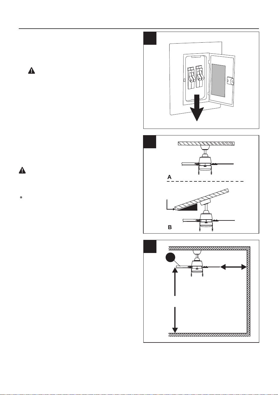
1. ADVERTENCIA: interrumpa el suministro de
energía hacia el ventilador apagando los
interruptores de circuito y el interruptor de
pared.
PELIGRO: si no desconecta el suministro
de electricidad antes de realizar la instalación,
se pueden producir lesiones graves o la
muerte.
3. Compruebe que las aspas (G) estén al menos
a 76.20 cm de cualquier obstáculo y al menos
a 2.13 m sobre el piso.
2. Determine el método de instalación que
utilizará.
A. Montaje estándar
B. Montaje en ángulo
IMPORTANTE: Si utiliza un montaje en
ángulo, asegúrese de que el ángulo del techo para
el ventilador AR73B-42" no sea más pronunciado
que 23° y para el ventilador AR73B-52" no sea más
pronunciado que 21°.
Consejo útil: el montaje estándar es mejor para
los techos de 2.13 m de alto o más. Para los
techos más altos, se recomienda utilizar una
varilla más larga (no incluida). El montaje en
ángulo es mejor para los techos en ángulo o de
bóveda. En ocasiones, es necesaria una varilla
más larga para asegurar una adecuada separación
de las aspas.
2,13 m
mín.
76.20 cm
mín.
AR73B-42”: 23° máx.
AR73B-52”: 21° máx.
28
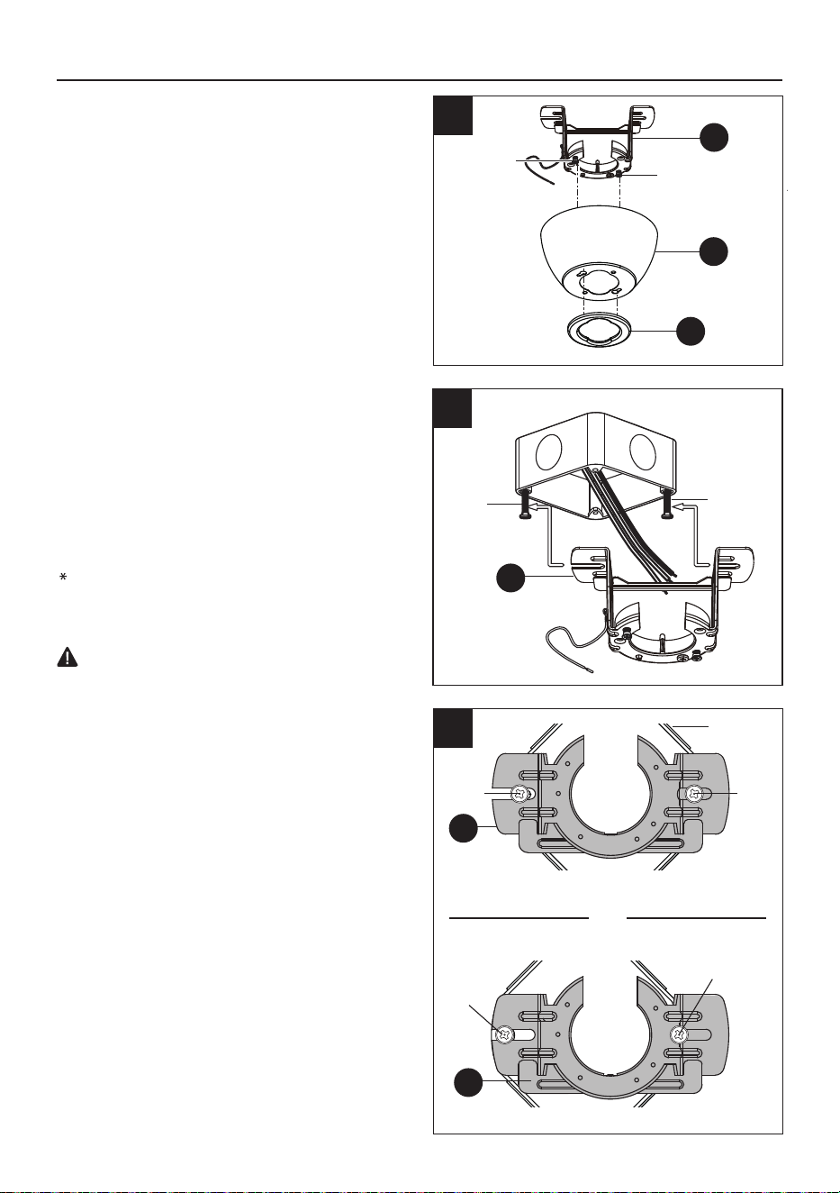
1
2A
2B.
INSTALACIÓN DEL VENTILADOR
Proporcione una imagen del deslizador en el
soporte de montaje (A) con la posición
correcta del tornillo.
1. Retire la cubierta inferior de la base (C) de la
base (B) girándola (C) en dirección contraria
a las manecillas del reloj.
Afloje media vuelta los tornillos de montaje
de la base, desde la cabeza del tornillo, para
retirar el soporte de montaje (A) de la base
(B). Después, gire la base (B) en dirección
contraria a las manecillas del reloj para retirar
el soporte de montaje (A) de la base (B).
Tornillo de
montaje de
la base
Tornillo de
montaje de
la base
2A. Fije el soporte de montaje (A) en la caja de
salida deslizando el soporte de montaje (A)
sobre los tornillos proporcionados con la
caja de salida. Tenga en cuenta que el lado
plano del soporte de montaje (A) está
orientado hacia la caja de salida.
Ajuste firmemente los dos tornillos de montaje.
NOTA: es muy importante que use los
aditamentos adecuados para instalar el soporte de
montaje (A), ya que este soportará el ventilador.
IMPORTANTE: si realiza el montaje en
ángulo, asegúrese de que el extremo abierto del
soporte de montaje (A) esté instalado en dirección
hacia el punto más alto del techo.
Tornillos
para la
caja de
salida
Tornillos
para la
caja de
salida
A
A
B
C
2B
Caja de
salida
POSICIÓN CORRECTA del tornillo
A
Tornillo
Tornillo
Posición
del tornillo
Posición
del tornillo
VS
POSICIÓN INCORRECTA del tornillo
(vista desde
abajo)
(vista desde
abajo)
A
29
3. Retire el pasador de chaveta y el pasador de
horquilla, y afloje los dos tornillos de fijación
del collar del motor.
Inserte la varilla (D) a través de la base (B),
la cubierta inferior de la base (C) y la cubierta
del acoplador (E). Pase los conductores
desde el ensamble del motor de ventilador
(F) a través de la varilla (D).
4.
Inserte la varilla (D) en el anillo, alinee los
orificios y vuelva a instalar el pasador de
horquilla y el pasador de chaveta. Apriete los
tornillos de fijación en el anillo.
5.
INSTALACIÓN DEL VENTILADOR
Pasador de
chaveta
Anillo
Tornillo de
fijación
Tornillo de
fijación
Pasador de
chaveta
3
Tornillo de
fijación
Anillo
Tornillo de
fijación
Pasador
de horquilla
4
F
C
E
B
D
D
5
Pasador
de horquilla
30
INSTALACIÓN DEL VENTILADOR
Lengüeta
Levante con cuidado el ensamble del motor
del ventilador (F) hasta el soporte de montaje
(A) y asiente la varilla (D) en el
portalámparas del soporte de montaje (A).
Asegúrese de que la lengüeta del
portalámparas del soporte de montaje (A)
esté bien asentada en la ranura de la varilla
(D). Esto ayudará a equilibrar el ventilador de
techo.
6.
PELIGRO: la alineación incorrecta de la
ranura de la bola con la lengüeta puede
provocar que el ventilador se balancee o se
caiga, lo que podría causar lesiones graves o
la muerte.
Ranura
A
6
F
D
CABLEADO
ADVERTENCIA: para reducir el riego de incendios, descargas eléctricas o lesiones personales,
los conectores de alambres proporcionados con este ventilador están diseñados para soportar solo
un cable de la casa de calibre 12 y dos cables conductores del ventilador. Si el cable de la casa es
de un calibre superior a 12 o hay más de un cable de la casa para conectar a los dos cables
conductores del ventilador, pregúntele a un electricista cuál es el tamaño adecuado de los
conectores de alambres que debe utilizar.
NOTA: este ventilador puede adaptarse para control remoto (el control remoto no se incluye). Si decide
comprar un control remoto para usar con el ventilador, tenga en cuenta que la función de regulación de
la luz no quedará operativa. La capacidad de regulación de esta luz solo es posible con la utilización de
controles de pared que controlen el ventilador y la luz por separado, como por ejemplo el WM-7WWL
(no se incluye).
ADVERTENCIA: si los conductores de la casa no tienen los mismos colores que se
mencionan en los pasos siguientes, deténgase de inmediato. Se recomienda que un electricista
profesional determine el cableado adecuado.
PRECAUCIÓN: asegúrese de que la caja de salida tenga la puesta a tierra correcta y de que
haya un conductor (verde o desnudo) de puesta a tierra.
Según el largo de la varilla que utilice, es
posible que necesite cortar los cables
conductores para simplificar el cableado. Si
decide cortar los cables conductores, se
sugiere hacerlo de la siguiente manera:
Sujete los cables conductores y asegúrese
de jalarlos completamente a través de la
parte superior de la varilla. Comience en la
parte SUPERIOR de la bola en la varilla y
mida 20.32 cm de cable conductor y corte el
exceso de cable con las pinzas cortacables
(no se incluyen).
1A.
Colgador
Bola
20.32 cm
1A
31
NOTA: si no cortó los cables conductores,
los Pasos 1A y 1B no son necesarios y
puede proceder con el Paso 2 en su
lugar.
Si decidió cortar los cables conductores en
el paso 1A, pele 1.27 cm del aislamiento del
extremo del conductor blanco. Tuerza los
extremos pelados de cada filamento de
cable dentro del aislante con pinzas (no
incluidas). Repita el Paso 1B para los
conductores negro, azul (si corresponde) y
verde.
1B.
1B
Este ventilador de techo incluye dos tipos de
conectores: un conector de 2 conductores
(AA) y un conector de 3 conductores (BB).
Seleccione el conector adecuado para sus
necesidades de cableado.
CABLEADO DEL CONECTOR DE
ALAMBRES: primero, empuje el mango de
retención del conector hacia arriba; luego,
empuje el conductor en el orificio de
conexión y presione la manija de retención
hacia abajo para asegurar el cable.
Escoja el diagrama de cableado (Fig. 3A,
Fig. 3B o Fig. 3C) que se ajuste a su
situación y realice las conexiones del
cableado adecuadas como se indica a
continuación:
3A. VENTILADOR Y LUZ CONTROLADOS
POR CADENAS DE TIRO: conecte el cable
NEGRO y AZUL del ventilador al cable
NEGRO del techo. Conecte el cable
BLANCO del ventilador al cable BLANCO
del techo. Conecte todos los cables de
PUESTA A TIERRA (VERDES) juntos
desde el ventilador (en la varilla [D] y el
soporte de montaje [A]) con el cable
DESNUDO o VERDE del techo.
2.
Alimentación de
120 v desde el techo
Cables
Mango fijo
Mango fijo
Cables
2
3.
3A
VENTILADOR Y LUZ CONTROLADOS POR CADENAS DE TIRO
Negro (alimentación)
Blanco (neutro)
Puesta a tierra/verde (desnudo)
AA
AA
ABAJO
HACIA ARRIBA
ENTRADA
Verde
Blanco
Azul
Negro
Negro
32
CABLEADO
3B. VENTILADOR CONTROLADO POR LA
CADENA DE TIRO Y LUZ CONTROLADA
POR EL INTERRUPTOR DE PARED: si
desea controlar la luz del ventilador con un
interruptor de pared independiente, conecte el
cable NEGRO del ventilador al cable NEGRO
del techo. Conecte el cable AZUL del ventilador
al cable NEGRO del interruptor de pared
independiente para la luz. Conecte el cable
BLANCO del ventilador al cable BLANCO del
techo con una tuerca para cable (no incluida).
Conecte todos los cables de PUESTA A
TIERRA (VERDES) juntos desde el ventilador
(en la varilla [D] y el soporte de montaje [A])
con el cable DESNUDO o VERDE del techo.
3C. VENTILADOR Y LUCES CONTROLADOS
POR DOS INTERRUPTORES DE PARED: si
desea controlar el ventilador y la luz con
interruptores de pared separados, conecte el
cable NEGRO del ventilador al cable NEGRO
del interruptor de pared independiente para el
ventilador. Conecte el cable AZUL del ventilador
al cable NEGRO del otro interruptor de pared
independiente para la luz. Conecte el cable
BLANCO del ventilador al cable BLANCO del
techo con una tuerca para cable (no incluida).
Conecte todos los cables de PUESTA A
TIERRA (VERDES) juntos desde el ventilador
(en la varilla [D] y el soporte de montaje [A]) con
el cable DESNUDO o VERDE del techo.
NOTA: el cable NEGRO es el que proporciona
alimentación al ventilador. El conductor AZUL
es el que proporciona alimentación al kit de
luces. El conductor BLANCO es el mismo para
el ventilador y el kit de luces. El cable
DESNUDO/VERDE es la puesta a tierra.
ADVERTENCIA: si utiliza un interruptor
de pared para atenuar una lámpara, NO
utilice una cadena de tiro simultáneamente.
Esto dañará la lámpara.
ADVERTENCIA: asegúrese de que no
haya cables desnudos ni filamentos de
cables visibles después de hacer las
conexiones. Coloque los conductores
VERDES y BLANCOS en el lado opuesto de
los conductores NEGROS y AZULES de la
caja (si corresponde).
Blanco (neutro)
Puesta a tierra/verde (desnudo)
Negro (interruptor de pared)
3C
Alimentación de
120 v desde el techo
VENTILADOR Y LUZ CONTROLADOS POR DOS
INTERRUPTORES DE PARED
Gire los conductores empalmados o
cubiertos con cinta hacia arriba y empuje
suavemente los conductores y los
conectores de alambres (AA y BB) hacia
dentro de la caja de salida.
Cubra con cinta aislante (no se incluye) cada
conector de alambres (AA y BB) individual
hacia abajo del conductor.
4.
Aditamentos utilizados
Conector de 3 conductores x 2
Conector de 2 conductores x 1
AA
BB
4
BB
BB
AA
Alimentación de
120 v desde el techo
3B
Negro (alimentación)
Blanco (neutro)
Puesta a tierra/verde (desnudo)
VENTILADOR CONTROLADO POR CADENA DE TIRO Y LUZ
CONTROLADA POR INTERRUPTOR DE PARED
Negro
Blanco
Verde
Negro
(interruptor
de pared
para luz)
Azul
Blanco
Verde
Negro
(interruptor
de pared)
Negro
Azul
33
5
CABLEADO
5. IMPORTANTE: el uso de un regulador de
intensidad de rango completo (no se incluye)
para controlar la velocidad del ventilador
provocará un zumbido intenso del ventilador.
Para reducir el riesgo de incendios o
descargas eléctricas, NO use un regulador de
intensidad de rango completo para controlar
la velocidad del ventilador.
1
2
3
Regulador de
intensidad
Regulador de
velocidad
Solo con fines ilustrativos. No pretende cubrir
todos los tipos de controles.
INSTALACIÓN FINAL
Asegúrese de que los cables estén bien
colocados en la caja de salida del techo.
Desplace la base (B) sobre el soporte de
montaje (A), de manera tal que se alineen
los orificios principales en la base (B), sobre
los tornillos de montaje de la base aflojados
en el soporte de montaje (A). Gire la base (B)
en dirección de las manecillas del reloj hasta
que la base (B) se trabe en su lugar en la
sección estrecha de los orificios principales.
Alinee los orificios pasador de posicionamiento
en la base (B) con los orificios restantes en el
soporte de montaje (A). Apriete con firmeza
los dos tornillos de montaje de la base.
1.
Fije la cubierta inferior de la base (C) a la
base (B) insertando las cabezas de los
tornillos en las ranuras principales en la
cubierta inferior de la base (C) y girándola en
dirección de las manecillas del reloj.
NOTA: ajuste los tornillos de montaje de la
base como sea necesario hasta que la base
(B) y su cubierta de la parte inferior (C) estén
ajustadas.
2.
Pasador de
posicionamiento
Tornillo de
montaje de
la base
Tornillo de
montaje
de la base
2
1
B
A
B
C
Orificio
34
3.
ADVERTENCIA: si no se colocan
correctamente las aspas (G) en los brazos de
las aspas (H) y no se engancha el mecanismo
de bloqueo con resorte, las aspas del
ventilador (G) podrían aflojarse y
posiblemente caerse.
Sujete el aspa (G) con las manos cerca del
brazo del aspa (H), alinee los orificios de la
ranura con los postes del brazo del aspa y
presione el aspa hacia abajo firmemente.
Compruebe que los orificios con forma de
cerradura se asienten correctamente en los
postes del brazo del aspa.
Deslice firmemente el aspa (G) lejos del brazo
del aspa (H) hasta que el aspa (G) se
enganche en el mecanismo de bloqueo con
resorte. Asegúrese de que el resorte del
mecanismo de bloqueo con resorte esté hacia
arriba y que la parte posterior del mecanismo
de bloqueo con resorte esté contra el borde
del aspa.
Para separar el aspa (G) del brazo del aspa (H):
Presione hacia abajo el mecanismo de
bloqueo con resorte para liberar el aspa (G)
del brazo del aspa (H). Deslice el aspa (G)
hacia el brazo del aspa (H) hasta que el
aspa (G) se desenganche del mecanismo
de bloqueo con resorte, empuje con
cuidado el aspa (G) hacia arriba para
separarla del brazo del aspa (H).
3
G
H
H
G
Orificios con
forma de
cerradura
Postes del brazo
del aspa
Mecanismo de bloqueo
con resorte
Mecanismo de bloqueo
con resorte
INSTALACIÓN FINAL
4.
ADVERTENCIA: para reducir el riesgo de
lesiones personales, no introduzca objetos
extraños entre las aspas del ventilador en
movimiento (G).
Fije el brazo del aspa (H) al ensamble del
motor del ventilador (F) al alinear los orificios
de los brazos del aspa (H) y el ensamble del
motor del ventilador (F).
Apriete los dos tornillos del brazo del aspa
con arandelas de seguridad ya instaladas en
los brazos de las aspas (H). Repita este
procedimiento con los demás brazos de las
aspas (H).
4
F
H
Tornillos Tornillos
Retire los
soportes de
goma del
empaque.
35
INSTALACIÓN FINAL
Vuelva a instalar los dos tornillos de montaje
de la carcasa del interruptor que acaba de
quitar en el anillo de montaje de la carcasa
del interruptor. (No apriete). Mientras
sostiene la carcasa del interruptor (I) debajo
del ensamble del motor del ventilador (F),
ensamble el enchufe de las conexiones de
cableado con el enchufe de 9 clavijas de la
carcasa del interruptor (I).
Coloque los orificios guía en la carcasa del
interruptor (I) sobre los dos tornillos aflojados
anteriormente en el anillo de montaje. Gire la
carcasa del interruptor (I) hasta que encaje en
su lugar en la sección estrecha de los orificios
guía. Asegure los dos tornillos de montaje que
aflojó y el que quitó anteriormente.
5.
PRECAUCIÓN: antes de comenzar la
instalación, desconecte la alimentación
colocando el interruptor de circuito en la
posición de apagado o retirando el fusible de
la caja de fusibles. No basta con colocar el
interruptor del ventilador en la posición de
apagado para evitar descargas eléctricas.
5
F
I
Anillo de montaje
de la carcasa del
interruptor
Conectores de cables
Tornillos de
montaje
Retire uno de los tres tornillos de montaje del
kit de luces de la carcasa del interruptor (I) y
afloje los otros dos tornillos de montaje del kit
de luces. (No los retire).
Mientras sostiene el kit de luces LED de 19
W (J) debajo del ensamble del motor del
ventilador (F), haga las conexiones de
cableado de 2 clavijas.
Coloque los orificios guía en el kit de luces
LED de 19 W (J) sobre los dos tornillos de
montaje aflojados anteriormente de la
carcasa del interruptor (I). Gire el kit de luces
LED de 19 W (J) hasta que se ubique en su
lugar en la sección estrecha de los orificios
guía. Asegúrelo al apretar los dos tornillos de
montaje del kit de luces que aflojó antes y el
que quitó anteriormente.
6.
F
J
I
6
Tornillos de
montaje
Conectores
de cables
36
INSTALACIÓN FINAL
7.
Levante la pantalla de plástico (K) contra el kit
de luces LED de 19 W (J) y asegúrela al
ventilador girando la pantalla de plástico (K) en
dirección de las manecillas del reloj, hasta que
quede ajustada. NO APRIETE DEMASIADO.
Instale la cadena y la cadenilla de tiro (L) en
aquellas ubicadas en la carcasa del
interruptor (I).
8.
K
J
7
I
L
8
37
INSTRUCCIONES DE FUNCIONAMIENTO
1.
2.
El interruptor de reversa está ubicado en la
superficie de la carcasa del interruptor (I).
Deslice el interruptor hacia la izquierda para
que funcione en climas cálidos. Deslice el
interruptor hacia la derecha para que
funcione en climas fríos.
NOTA: espere a que el ventilador se detenga
antes de invertir la dirección de rotación de
las aspas.
PRECAUCIÓN: al instalar el interruptor de
pared o el control remoto, asegúrese de que
el interruptor de cadena del ventilador esté
en la posición de "VELOCIDAD ALTA" y tire
hacia abajo y mantenga la luz en la posición
de BRILLO MÁXIMO; luego podrá usar un
interruptor de pared para atenuar la luz.
3A. Clima cálido (en dirección contraria a las
manecillas del reloj) Un flujo de aire
descendente crea un efecto de enfriamiento.
Esto permite establecer el aire acondicionado
en un ajuste más cálido sin afectar la
comodidad.
3B. Clima frío (en dirección de las manecillas del
reloj) Un flujo de aire ascendente mueve el
aire cálido fuera del techo. Esto permite
establecer la unidad de calefacción en un
ajuste de temperatura más frío sin afectar la
comodidad.
2
3A
3B
I
1
La cadena de tiro controla la velocidad del
ventilador de la siguiente forma: al tirar 1 vez,
alta; al tirar 2 veces, media; al tirar 3 veces,
baja; al tirar 4 veces, se apaga.
La cadena de tiro de la luz controla el kit de
iluminación: "ENCENDIDO" y "APAGADO" o
"REGULABLE". Para encender o apagar la
luz, jale hacia abajo y suelte inmediatamente.
Deslice hacia abajo y mantenga la posición; el
brillo aumentará o disminuirá continuamente.
El kit de iluminación conserva el ajuste de
brillo anterior después de apagarse.
1.
38
Compruebe las conexiones de soporte, los soportes y las fijaciones de las aspas dos veces al año.
Cerciórese de que estén aseguradas. Debido al movimiento natural del ventilador, algunas
conexiones pueden soltarse con el tiempo. No es necesario retirar el ventilador del techo. Limpie el
ventilador periódicamente. Use solo un cepillo suave o un paño sin pelusas para evitar rayar el
acabado. El enchapado está sellado con una laca que reduce al mínimo la decoloración o el
deslustre.
IMPORTANTE: Antes de realizar cualquier trabajo de mantenimiento, desconecte el suministro
principal de electricidad. No utilice agua ni un paño húmedo para limpiar el ventilador de techo.
CUIDADO Y MANTENIMIENTO
SOLUCIÓN DE PROBLEMAS
PROBLEMA CAUSA POSIBLE ACCIÓN CORRECTIVA
El ventilador no
se mueve.
1. El interruptor de reversa no
está activado.
2. No hay electricidad o hay un
fusible quemado.
3. La conexión de los
conductores es incorrecta.
4. Los enchufes no están
conectados adecuadamente.
1. Mueva firmemente el interruptor hacia la
izquierda o hacia la derecha.
2. Conecte la alimentación eléctrica o revise
el fusible.
3. Desconecte la alimentación. Afloje la base
y revise todas las conexiones.
4. Verifique que los conectores de alambres
de la carcasa del interruptor estén bien
conectados de acuerdo con las instruc-
ciones de la página 15.
El funcionamiento
es ruidoso.
1. Las aspas están flojas.
2. Las aspas están flojas.
3. Se está utilizando un regulador
de intensidad de rango
completo.
4. El ventilador es nuevo, el
motor necesita período de
asentamiento.
1. Los brazos de las aspas no
están ajustados
correctamente.
2. Las aspas no están
equilibradas.
3. El ventilador no está colocado
firmemente.
4. El ventilador está demasiado
cerca del techo abovedado.
5. Los tornillos de fijación en la
horquilla de la carcasa del
motor no están bien ajustados.
6. El tornillo de fijación en la bola
para colgar no está bien
ajustado.
1. Apriete todos los tornillos de las aspas.
2. Reemplace el aspa.
3. Reemplace por un dispositivo de control
de velocidad autorizado.
4. Permita que el ventilador tenga un período
de asentamiento de un par de días,
especialmente al encender el ventilador a
velocidades media y alta.
Balanceo
excesivo.
1. Vuelva a instalar los brazos de las aspas.
2. Intercambie un aspa con otra del lado
opuesto. O bien, equilibre el ventilador
mediante el kit de equilibrio del aspa (se
vende por separado).
3. Desconecte la alimentación. Afloje
cuidadosamente la base y verifique que el
soporte de montaje esté firme.
4. Utilice una varilla más larga o mueva el
ventilador a otra ubicación.
5. Apriete firmemente los tornillos de fijación
de la horquilla.
6. Afloje y baje cuidadosamente la base y
verifique que el tornillo de fijación de la
bola para colgar esté bien apretado.
ADVERTENCIA: antes de comenzar cualquier trabajo, desconecte el suministro de electricidad
para evitar descargas eléctricas.
39
NOTA: cierto "balanceo" es normal y no se debe considerar como un defecto.
SOLUCIÓN DE PROBLEMAS
El ventilador funciona
pero la luz no.
1. Los conductores de la base no
están bien conectados.
2. El interruptor de pared del
ventilador está apagado.
3. Los enchufes no están
conectados adecuadamente.
1. Revise los conductores de la base y,
si es necesario, vuelva a conectarlos
de acuerdo con las instrucciones de
las páginas 11 y 12.
2. Asegúrese de que el interruptor de
pared del ventilador esté en la
posición de encendido.
3. Verifique que los conectores de
alambres de la carcasa del interruptor
estén bien conectados de acuerdo
con las instrucciones de la página 15.
El distribuidor garantiza que este ventilador no presenta defectos de mano de obra ni en los
materiales presentes al momento del envío desde la fábrica durante un período de garantía limitada
de por vida a partir de la fecha de compra. Esta garantía es válida solo para el comprador original. El
distribuidor acepta reparar cualquier defecto sin cargo o, según nuestro criterio, remplazar el
ventilador de techo por un modelo similar o superior.
Para obtener el servicio de garantía, presente una copia del recibo de venta como comprobante de la
compra. Todos los costos de extracción y reinstalación son responsabilidad absoluta del comprador.
Cualquier daño al ventilador de techo producido por accidente, uso indebido o instalación incorrecta, o
por el uso de piezas no producidas por el fabricante de este ventilador o accesorios de fijación que no
son del fabricante de este ventilador, será responsabilidad del comprador. El distribuidor no asume
ningún tipo de responsabilidad por la instalación del ventilador durante la garantía limitada de por
vida. Cualquier servicio realizado por una persona no autorizada invalidará la garantía.
Debido a las cambiantes condiciones climáticas, esta garantía no cubre cambios en el acabado de
latón, óxido, picaduras, deslustre, corrosión o descascarado. Los ventiladores con acabado de latón
mantienen su belleza cuando se los protege de las condiciones climáticas cambiantes. La garantía no
cubre los vidrios incluidos con este ventilador.
Cualquier reemplazo de piezas defectuosas para el ventilador de techo debe informarse dentro del
primer año a partir de la fecha de compra. Para conocer el saldo de la garantía, llame a nuestro
Departamento de Servicio al Cliente (al 888-251-1003) para obtener la autorización para la devolución
y las instrucciones de envío, de modo que podamos reparar o reemplazar el ventilador de techo. Un
ventilador o piezas devueltas con un embalaje incorrecto son de responsabilidad única del comprador.
No existe otro tipo de garantía explícita. El distribuidor rechaza cualquiera y todas las garantías
implícitas. La duración de cualquier garantía implícita que no pueda rechazarse se limita al período de
garantía limitada de por vida especificado en nuestra garantía. El distribuidor no se hará responsable
por daños accidentales, resultantes ni especiales que surjan en relación con el uso o el
funcionamiento del producto, excepto que la ley indique lo contrario. Esta garantía le otorga derechos
legales específicos, pero podría tener también otros derechos que varían según el estado. Esta
garantía sustituye cualquier garantía previa.
GARANTÍA LIMITADA DE POR VIDA
PROBLEMA CAUSA POSIBLE ACCIÓN CORRECTIVA
40
Para obtener piezas de repuesto, llame a nuestro Departamento de Servicio al Cliente al
888-251-1003, de lunes a domingo, de 8 a.m. a 8 p.m., hora estándar del Este. También puede
ponerse en contacto con nosotros a través de [email protected].
LISTA DE PIEZAS DE REPUESTO
Impreso en China
PIEZA
DESCRIPCIÓN PIEZAS #
Abrazadera de montajeA
B
C
D
E
G
Base
Cubierta inferior de la
base
Varilla
Cubierta del acoplador
H
Aspa
I
J
K
L
Brazo del aspa
Carcasa del interruptor
Kit de luces LED de 19 W
Cadena y cadenilla
de tiro
Pantalla de plástico
CUBIERTO POR LA GARANTÍA
SÍ/UN AÑO
SÍ/UN AÑO
SÍ/UN AÑO
SÍ/UN AÑO
SÍ/UN AÑO
SÍ/UN AÑO
SÍ/UN AÑO
SÍ/UN AÑO
SÍ/UN AÑO
SÍ/UN AÑO
SÍ/UN AÑO
SÍ/UN AÑO
8499531-A 8499535-A
8499532-A 8499536-A
8499531-B 8499535-B
8499532-B 8499536-B
8499531-C 8499535-C
8499532-C 8499536-C
8499531-D 8499535-D
8499532-D 8499536-D
8499531-E 8499535-E
8499532-E 8499536-E
8499531-G 8499535-G
8499532-G 8499536-G
8499531-H 8499535-H
8499532-H 8499536-H
8499531-I 8499535-I
8499532-I 8499536-I
8499531-J 8499535-J
8499532-J 8499536-J
8499531-K 8499535-K
8499532-K 8499536-K
8499531-L 8499535-L
8499532-L 8499536-L
A
B
D
E
G
I
J
C
H
K
L
AA
BB
&
AA
&
BB
8499531-AA 8499535-BB
8499532-AA 8499536-BB
Conector del juego de
conductores