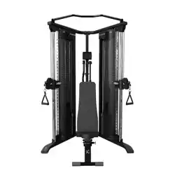
Health in Motion LLC
80432-EN-V2025-02-14
Record Serial Number Here
MADE IN CHINA
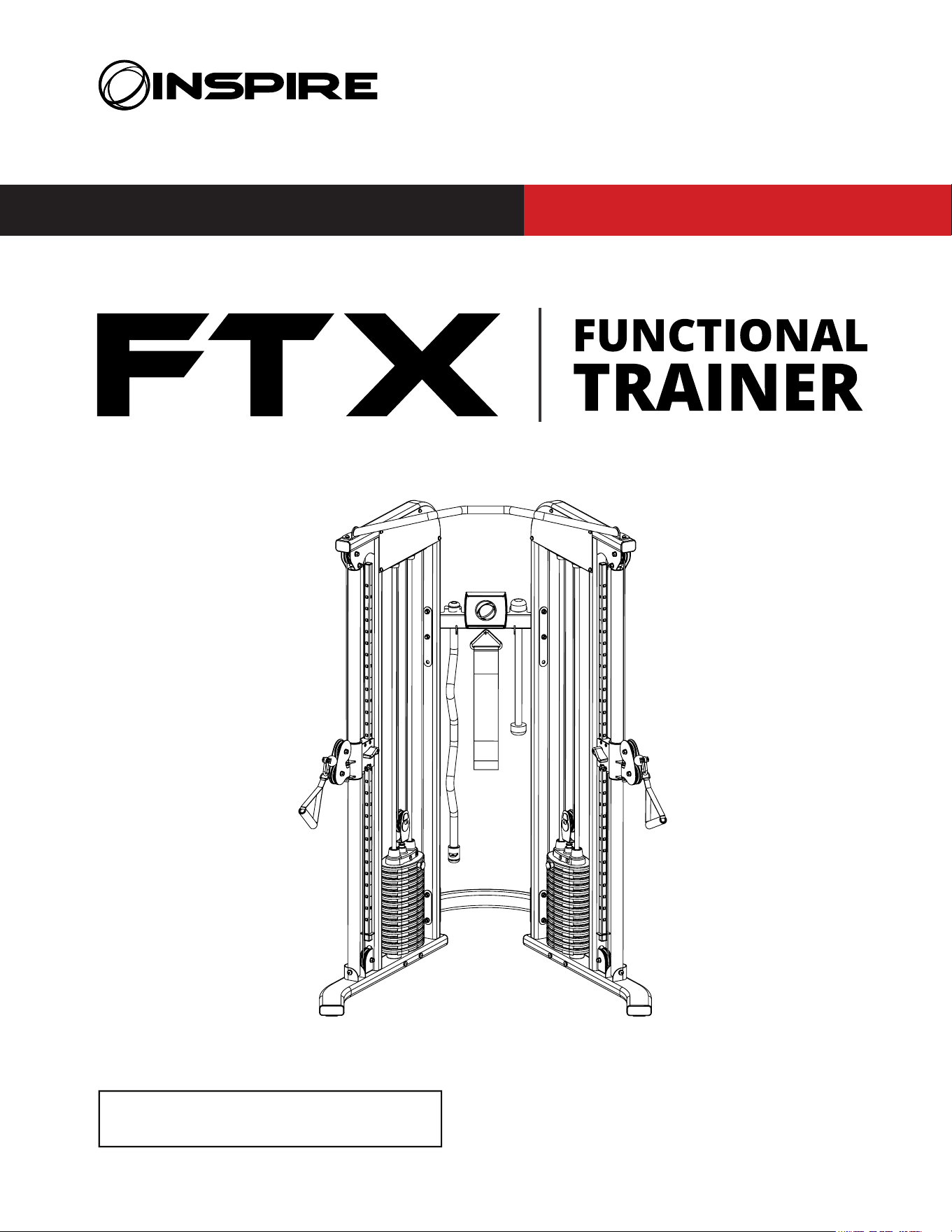
Model # FTX
USER MANUAL
START HERE
USER MANUAL

Pg. 380432-EN-V2025-02-14
CONGRATULATIONS
You’ve just taken the rst step to a healthier and stronger body. This functional trainer by Inspire oers the key to
unlocking your body’s potential. Regular strength training on a functional trainer has been shown to deliver a host of
benets including: increased muscle tone, decreased body fat, improved energy levels, a reduction in stress, and improved
cardiac output. Once again, congratulations, you are on your way to improving your self image, overall health, and quality
of life.
BEFORE ASSEMBLING YOUR HOME GYM
IMPORTANT: Read this entire manual before attempting to build or use this machine. This manual contains step by step
instructions for proper assembly.
Use the parts list included in this manual to verify that all parts are accounted for before assembly. If any parts are missing,
contact the retailer of this functional trainer for replacement parts. Or, call Inspire at 877-738-1729.
functional trainer to protect wood ooring or carpeting from damage during assembly and usage.
This functional trainer is intended for indoor use only. Rust can form on certain parts including guide rods in a humid environment,
resulting in impaired function.
Service of your functional trainer should only be performed by an authorized Inspire retailer. Service performed by anyone
else can result in loss of warranty. Support is provided in English and Spanish. If you need help nding an authorized
retailer, please contact us directly:
*Support is provided in English and Spanish*
Email
costcosupport@inspiretness.com
Phone
+1 877-738-1729 (US Only)
+1 714-738-1729 (Global)
Mon-Fri 8am-5pm PT - UTC-7h/8h
PRODUCT WARRANTY
To view full warranty details, or to register your product for warranty, visit inspiretness.com/support
AUSTRALIA
Our goods come with guarantees that cannot be excluded under the Australian Consumer Law. You are entitled to a replacement or
refund for a major failure and for compensation for any other reasonably foreseeable loss or damage. You are also entitled to have the
goods repaired or replaced if the goods fail to be of acceptable quality and the failure does not amount to a major failure.
Our goods and services come with guarantees that cannot be excluded under the Australian Consumer Law. For major failures with the
service, you are entitled:
• to cancel your service contract with us;
• to a refund for the unused portion, or to compensation for its reduced value.
You are also entitled to choose a refund or replacement for major failures with goods. If a failure with the goods or a service does not
amount to a major failure, you are entitled to have the failure rectied in a reasonable time. If this is not done you are entitled to a
refund for the goods and to cancel the contract for the service and obtain a refund of any unused portion. You are also entitled to be
compensated for any other reasonably foreseeable loss or damage from a failure in the goods or service.
Pg. 4 80432-EN-V2025-02-14
TABLE OF CONTENTS
PRODUCT WARRANTY..............................................................................3
IMPORTANT SAFETY NOTICE...................................................................5
FUNCTIONAL TRAINER ASSEMBLY INSTRUCTIONS..............................7
DECAL PLACEMENT.................................................................................11
LIVE AREA.................................................................................................12
PRODUCT DIMENSIONS.........................................................................13
MAINTENANCE........................................................................................14
MAINTENANCE SCHEDULE.....................................................................14
EXPLODED DIAGRAM..............................................................................15
PARTS LIST...............................................................................................16
Pg. 580432-EN-V2025-02-14
IMPORTANT SAFETY NOTICE
PRECAUTIONS
This exercise machine is built for optimum safety. However, certain precautions apply whenever you operate a piece of
exercise equipment. Be sure to read the entire manual before you assemble or operate your machine. Please note the
following safety precautions:
1. Always keep children and pets away from the machine. DO NOT leave children unattended in the same room with the
machine. The cabling and moving parts on this machine can cause serious injury or death if used improperly.
2. Only one person at a time should use the machine.
3. If the user experiences dizziness, nausea, chest pain, or any other abnormal symptoms, STOP the workout at once.
CONSULT A PHYSICIAN IMMEDIATELY.
4. Position the machine on a clear, leveled surface. DO NOT use the machine near water or outdoors.
5. Keep hands away from all moving parts.
6. Always wear appropriate workout clothing when exercising. DO NOT wear robes or other loose clothing that could
become caught in the machine. Running or training shoes are also required when using the machine.
7. Use the machine only for its intended use as described in this manual. DO NOT use attachments not recommended
by the manufacturer.
8. Do not place any sharp objects around the machine.
9. Disabled persons should not use the machine without a qualied person or physician in attendance.
10. Before using the machine to exercise, always do stretching exercises to properly warm up.
11. Never operate the machine if the machine is not functioning properly.
12. The FTX Functional Trainer is designed for home use only. Therefore, it does not have a weight stack cover.
This means the following for the user:
• Only one person may use the FTX Functional Trainer at the same time.
• The person must also ensure that no other person is in the exercise area of the FTX. Persons who are in the room
at the same time as the trainee must maintain a distance of at least 1.5 meters from the exercise equipment.
• After using the device, it must be secured in such a way that no unauthorized person has access to it.
Care and Maintenance
• Inspect and tighten all parts before using the machine.
• The Frame and Seat Pad of the machine can be cleaned using a damp cloth and mild non-abrasive detergent. DO NOT
use solvents.
WARNING: BEFORE BEGINNING ANY EXERCISE PROGRAM, CONSULT YOUR PHYSICIAN. THIS IS ESPECIALLY IMPORTANT FOR
INDIVIDUALS OVER THE AGE OF 35 OR PERSONS WITH PRE-EXISTING HEALTH PROBLEMS. READ ALL INSTRUCTIONS BEFORE USING ANY
FITNESS EQUIPMENT. Health In Motion, LLC. DOES NOT ASSUME ANY RESPONSIBILITY FOR PERSONAL INJURY OR PROPERTY DAMAGE
SUSTAINED BY OR THROUGH THE USE OF THIS PRODUCT.
Pg. 6 80432-EN-V2025-02-14
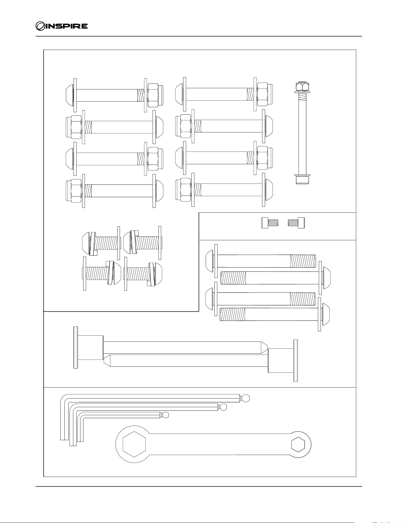
STEP 1
STEP 3
8 x Allen Bolt, M10 X 70 (19) 8 x Nut, M10 (24)
16 x Washer, M10 (25)
4 x Allen Bolt, M10 X 25 (20) 4 x Washer, M10 (25)
4 x Lock Washer, M10 (23)
4 x Allen Bolt, M10 X 80 (18)
4 x Washer, M10 (25)
1 x Bolt, M6 x 75 (28)
1 x Nut, M6 (30)
2 x Washer, M6 (29)
STEP 2
2 x Weight Selector Pin (9)
2 x Allen Bolt, M5 x 8 (22)
1 x #6 Allen Wrench (37)
1 x #5 Allen Wrench (38)
1 x # 4 Allen Wrench (39)
1 x #10 & #17 Wrench (40)
FTX.3
HARDWARE 1/1
80463-EN-V2025-02-14
240 mm
330 mm
Pg. 780432-EN-V2025-02-14
FUNCTIONAL TRAINER ASSEMBLY INSTRUCTIONS
STEP 1
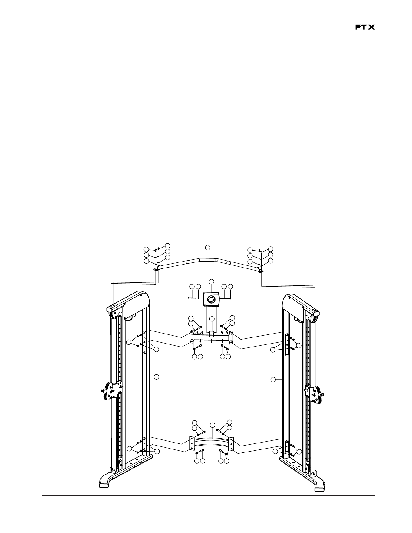
A. Do not tighten the Nuts and Bolts until instructed to do so.
B. Place the Lower Cross Brace (#4) between the Right & Left Stations (#1 & #2) in the mid-span.
C. Attach one end of the Lower Cross Brace to the Right Station. Secure it with two M10 x 70 Allen Bolts (#19) four Ø 10
Washers (#25), and two M10 Aircraft Nuts (#24). Repeat the same procedure to install the other side.
D. Repeat Procedure B & C to install the Upper Cross Brace (#5).
E. Place the Pull Up Bar Assembly (#3) on top of the Right and Left Stations.
F. Secure each end with two M10 x 25 Allen Bolts (#20), two Ø 10 ” Lock Washers (#23), and Ø 10 Washers (#25).
G. Place the Tablet Holder on to its mount and secure with a M6x75mm Allen Head Cap Screw (#28) and M6 Locknut
(#30), using M6 Washers (#29) on both sides. Tighten hardware until tablet holder holds its position but can still be
tilted up and down by hand.
H. Securely tighten all Nuts and Bolts installed.
1
2
3
4
5
19
25
19
25
19
25
19
25
19
25
19
25
19
25
19
25
25
24
24
25
20
23
25
20
23
25
20
23
25
20
23
25
25
24
24
25
27
28 29 29 30
Pg. 8 80432-EN-V2025-02-14
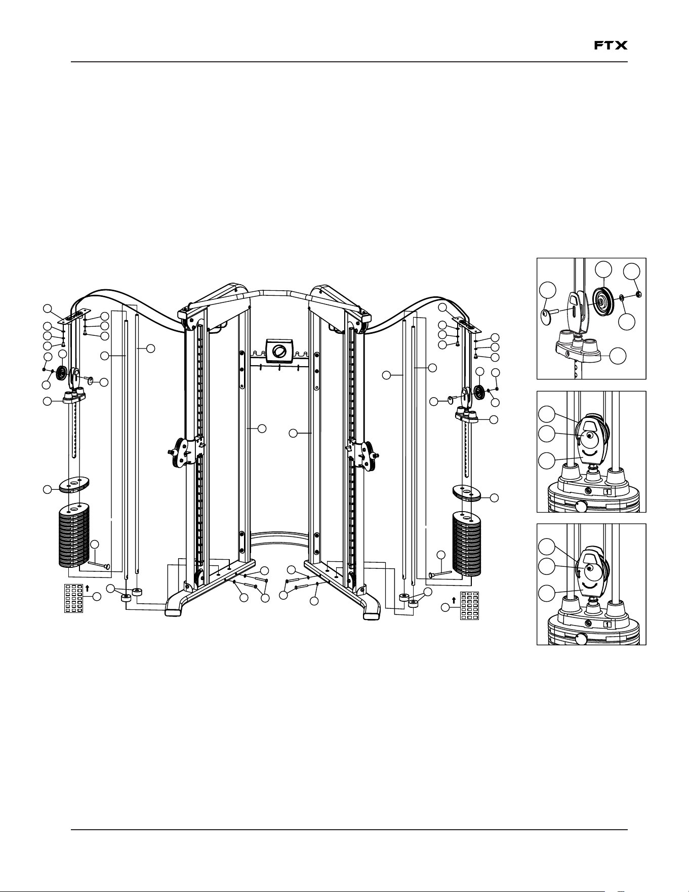
STEP 2
A. Install Guide Rods (#7) into holes on bottom Frame using M10 x 80 Allen Bolt (#18) and Ø 10 Spring Washers (#25).
Tighten.
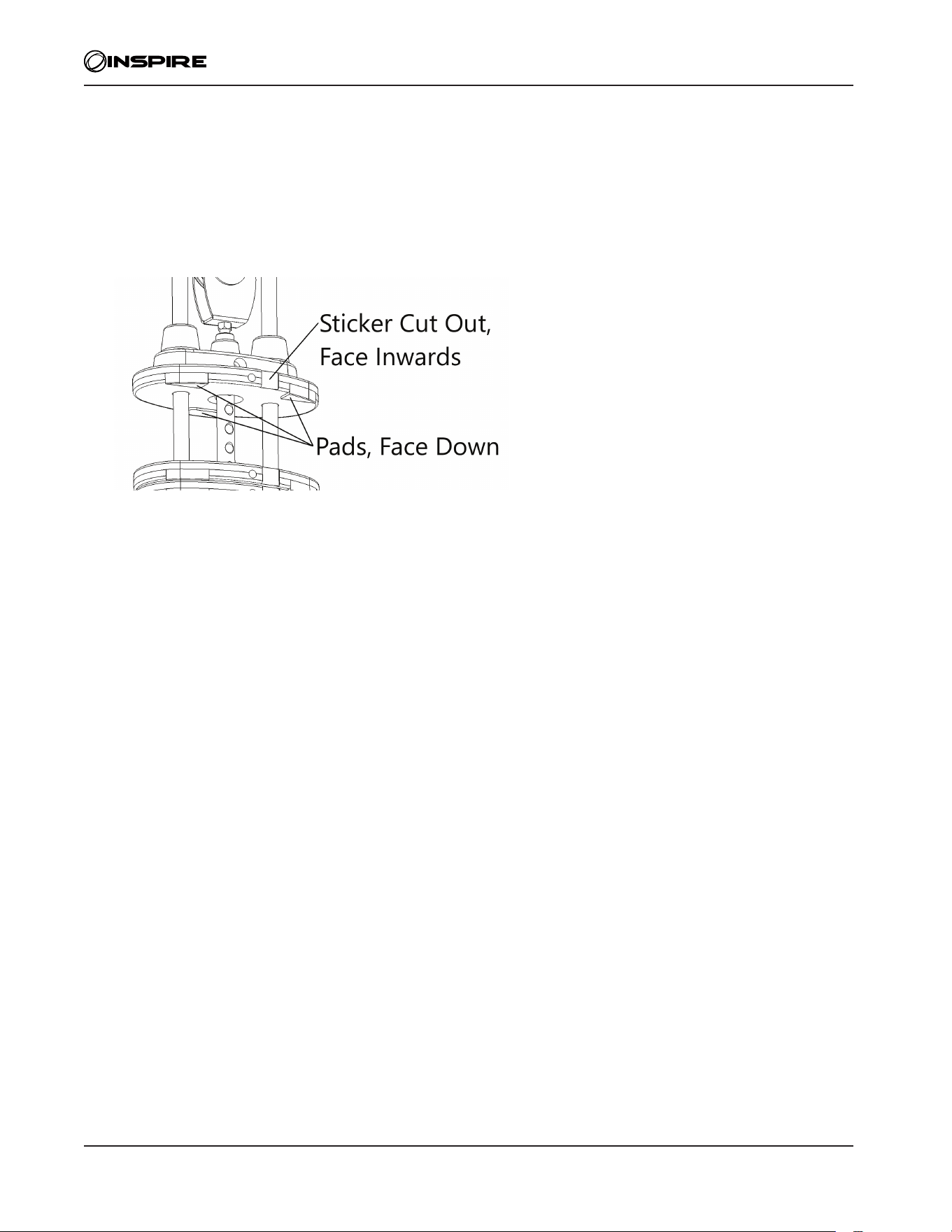
B. Install Rubber Bumpers (#16) on each Guide Rod (#7). Slide fteen 10lb Weight Plates (#10) from the top of Guide
Rods (#7) down to the Rubber Bumpers (#16). Make sure the weight sticker cut out is facing the inside of the machine
and the pads of the weight face down. See example below:
C. Remove the two M10 x 20 Allen Bolts (#21), Ø 10 Spring Washers (#23), and Ø 10 Washers (#25) which were pre-
assembled in the factory to hold the Guide Rod Bracket (#6). Slide the Selector Stem Assembly (#8) onto the Guide
Rods (#7). Install the weight stack Pulley (#33) with the cable wrapped between the pulley and the U shaped bracket
(#31). Then insert the Cam Bolt (#32) and secure with a Ø 10 Washer (#25), and a M10 Aircraft Nut (#24).
D. Hold the Selector Stem Assembly (#8) above the weight stack to make it easier to install Guide Rod Bracket (#6) on
Guide Rods (#7).
E. Once the Guide Rod Bracket (#6) is installed onto the Guide Rods (#7), Push the Guide Rod Bracket back into the
upright.
F. Secure the Bracket back to the upright frame with the two M10 x 21 Allen Bolts (#21), Ø 10 lock Washers (#23), Ø
10mm Washers (#25).
G. Lower the Selector Stem down onto the top of the weight stack.
H. Check all the cables to make sure they are on track on the pulleys.
I. Peel o the weight stack number label from the Resistance Label Set (#26) and attach to the plates, starting with
number one on the selector stem weight.
J. Insert the Weight Selector Pin (#9) into the weight stack.
K. Lubricate the Guide Rods with super lube or lube provided in Hardware Pack.
L. If Needed, Adjust the cable tension by loosening and rotating the Cam Bolt (#32) until the Selector Steam Assembly
(#8) starts lifting slightly from the weight stack. Tighten the nut of the cam bolt to lock it’s position.
M. Repeat the Procedure A through L above to install the other set of weight plates to the Left Station. (#2)
Pg. 980432-EN-V2025-02-14
1
2
6
25
23
21
7
7
8
9
10
16
18
25
25
25
23
21
6
25
23
21
25
23
21
7
7
8
9
10
16
18
25
25
26
1
2
3
4
5
6
7
8
15
9 16
10 17
11 18
12 19
13 20
14 21
26
1
2
3
4
5
6
7
8
15
9
16
10 17
11 18
12 19
13
20
14 21
32
25
24
33
32
25
24
33
8
32
25
24
33
31
32
33
31
32
33
Pg. 10 80432-EN-V2025-02-14
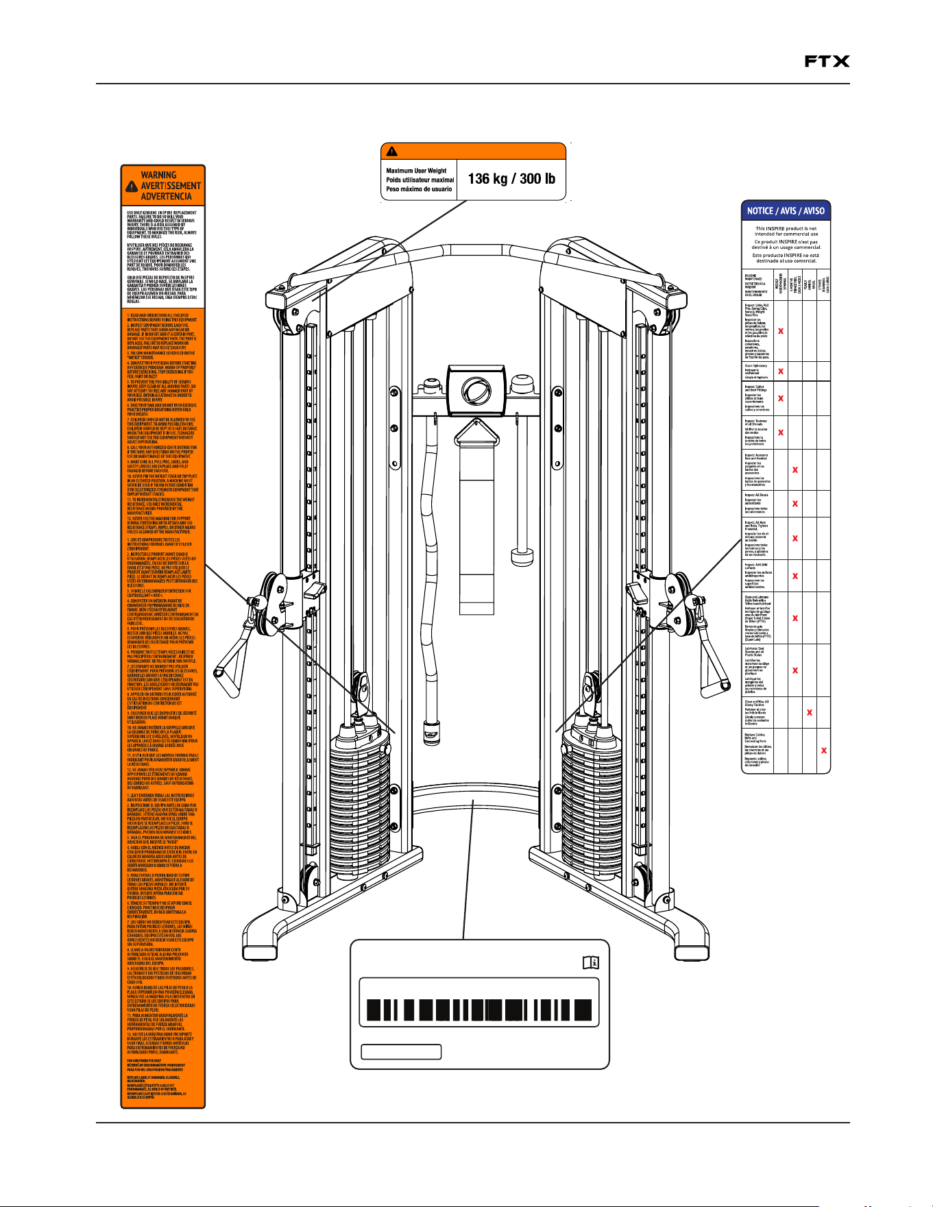
STEP 3
A. Attach the Height Adjustment Handle (#15) to the Left Lock Switch (#35) on the Pulley Carriage, secure it with one M5
x 10 Allen Bolt (#22). Repeat the same procedure to install the other side.
B. Connect the Single Handle (#13) to the Cable (#1) on the Right Station (#1) with a Spring Clip (#17). Repeat the same
procedure to install the other side.
C. Lift up the Height Adjustment Handle (#15) and slide the Pulley Carriage along the Pulley Carriage Support Frame to
the selected level. Release the Handle to lock the Pulley Carriage in position.
D. Store Curl Bar (#12), and Rope (#11) onto the Hanger Bracket behind the Upper Cross Brace (#5). Hang Chin Up Belt
(#14) on Upper Cross Brace (#5).
14
5
1
17
13
2
17
13
22
15
34
22
15
35
5
11
12
Pg. 1180432-EN-V2025-02-14
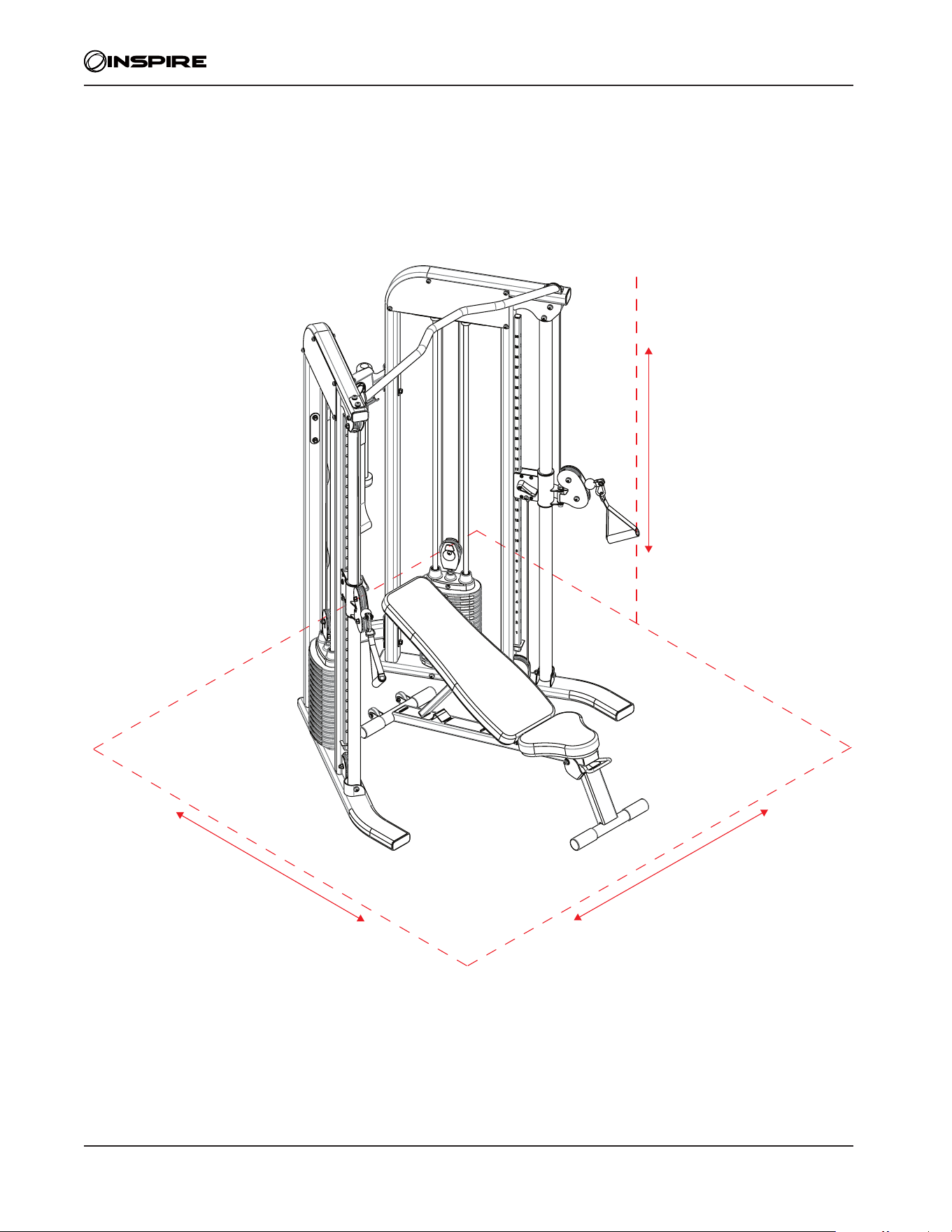
DECAL PLACEMENT
HEALTH IN MOTION, LLC
Made in china
Fabriqué en Chine
hecho en China
MODEL / Modèle / Modelo:
XXXX
XXXX.X-XXX-X-XX-XX-XXXXXX
Serial No. / No de série / N.° de serie:
+1 714-738-1729
Sales and service / Vente et
service / Ventas y servicios:
V2024-04-12
103052
3300 Horseless Carriage Drive, Norco, CA 92860
WARNING / AVERTISSEMENT / ADVERTENCIA
80458-V2025-02-03
Manufacture according to MFG-001 specification,
supplied by CENTR Engineering.
PMS 151 C
80458-V2025-02-03
64.4 mm
20 mm
80436-EN-ES-FR-V2024-12-18
Orange
151 C
80436-V2024-12-18
Manufacture according to MFG-001 specification,
supplied by CENTR Engineering.
508 mm
46 mm
80437-V2024-12-18
Manufacture according to MFG-001 specification,
supplied by CENTR Engineering.
45 mm
290 mm
80437-EN-ES-FR-V2024-12-18
273c8c
Pg. 12 80432-EN-V2025-02-14
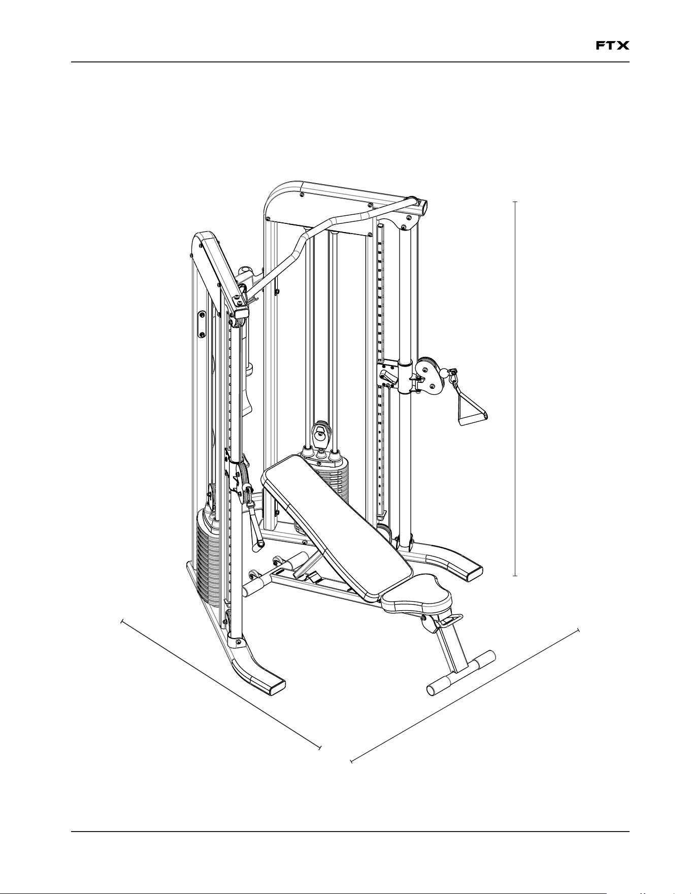
LIVE AREA
2.7 m
9 ft
9 pi
2.4 m
8 ft
8 pi
2.4 m
8 ft
8 pi
THE BENCH IS FOR
DISPLAY ONLY.
Pg. 1380432-EN-V2025-02-14
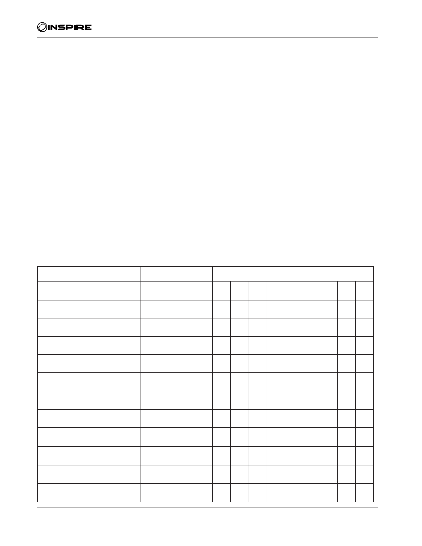
PRODUCT DIMENSIONS
137 cm
53.9 in
53.9 po
140 cm
55.1 in
55.1 po
210 cm
82.6 inch
82.6 po
THE BENCH IS FOR
DISPLAY ONLY.
Pg. 14 80432-EN-V2025-02-14
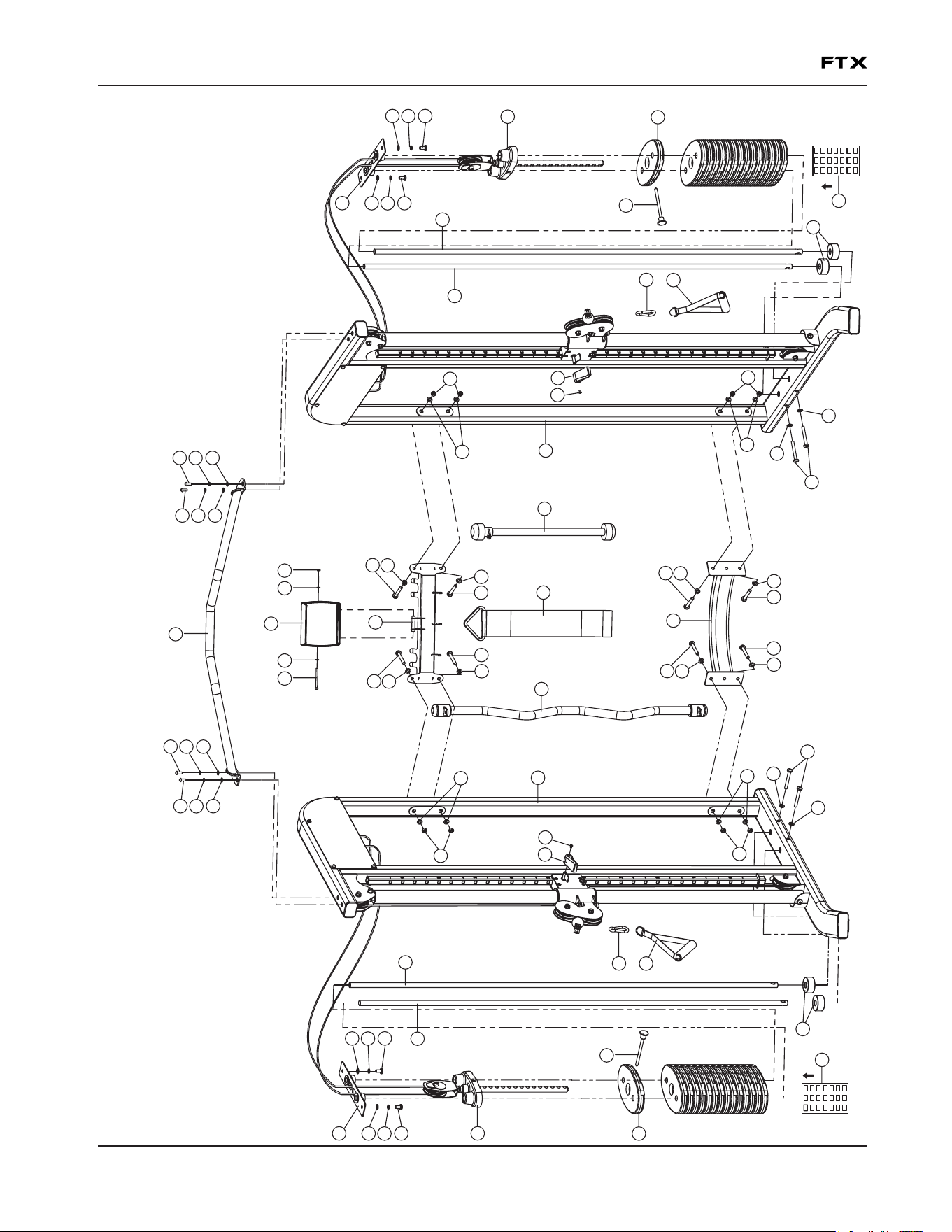
MAINTENANCE SCHEDULE
ROUTINE HOME MAINTENANCE ENTRY DATE
Inspect: Links, Pull Pins, Spring Clips,
Swivels, Weight Stack Pins
WEEKLY
Clean: Upholstery
WEEKLY
Inspect: Cables and their Fittings
WEEKLY
Inspect: Tautness of all Shrouds
WEEKLY
Inspect: Accessory Bars and Handles
3 MONTHS
Inspect: All Decals
3 MONTHS
Inspect: All Nuts and Bolts.
Tighten if Needed
3 MONTHS
Inspect: Anti-Skid surfaces
3 MONTHS
Clean and Lubricate: Guide Rods
with a Teon based lubricant
3 MONTHS
Lubricate: Seat Sleeves and
all Plastic Slides
3 MONTHS
Clean and Wax: All Glossy Finishes
YEARLY
Replace: Cables, Belts and
Connecting Parts
2 YEARS
MAINTENANCE
Warning
DO NOT place styrofoam or printed materials on the seat pads. Over time, these may stick to the pads and mar the
surface.
DO NOT leave items sitting on the seat pads, these pads have a special density that takes shape to objects and small
objectswill leave imprints in the surface that may take time to come out.
• Periodically inspect the cables for splitting, cracking or fraying. Also watch for bulging or at areas in the cable.
• Immediately replace cables at the rst signs of damage or wear. Never use equipment with damaged or worn cables.
• Cables naturally stretch over time, so check cable slack periodically and adjust cable tension as needed.
• Regularly inspect product for loose hardware.
• Do not use or store equipment outdoors.
• Inspect snap links, swivels, handles and weight stack pin for wear or damage. If wear or damage exists,
replace with Inspire Fitness parts only.
• Locate and familiarize yourself with all warning decals on the Smith Machine Functional Trainer.
• Replace damaged or worn upholstery immediately.
• Periodically wipe down guide rods with a dry cloth and re-apply a thin coat of a Teon™ based lubricant.
Pg. 1580432-EN-V2025-02-14
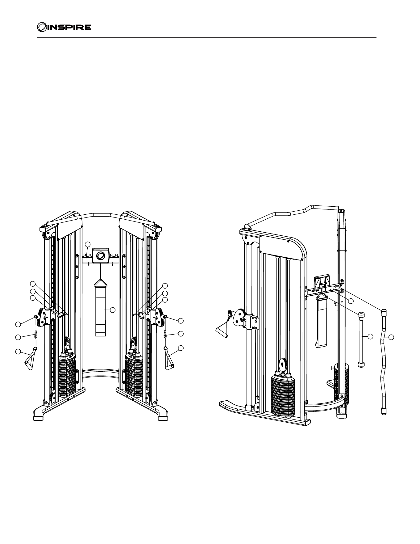
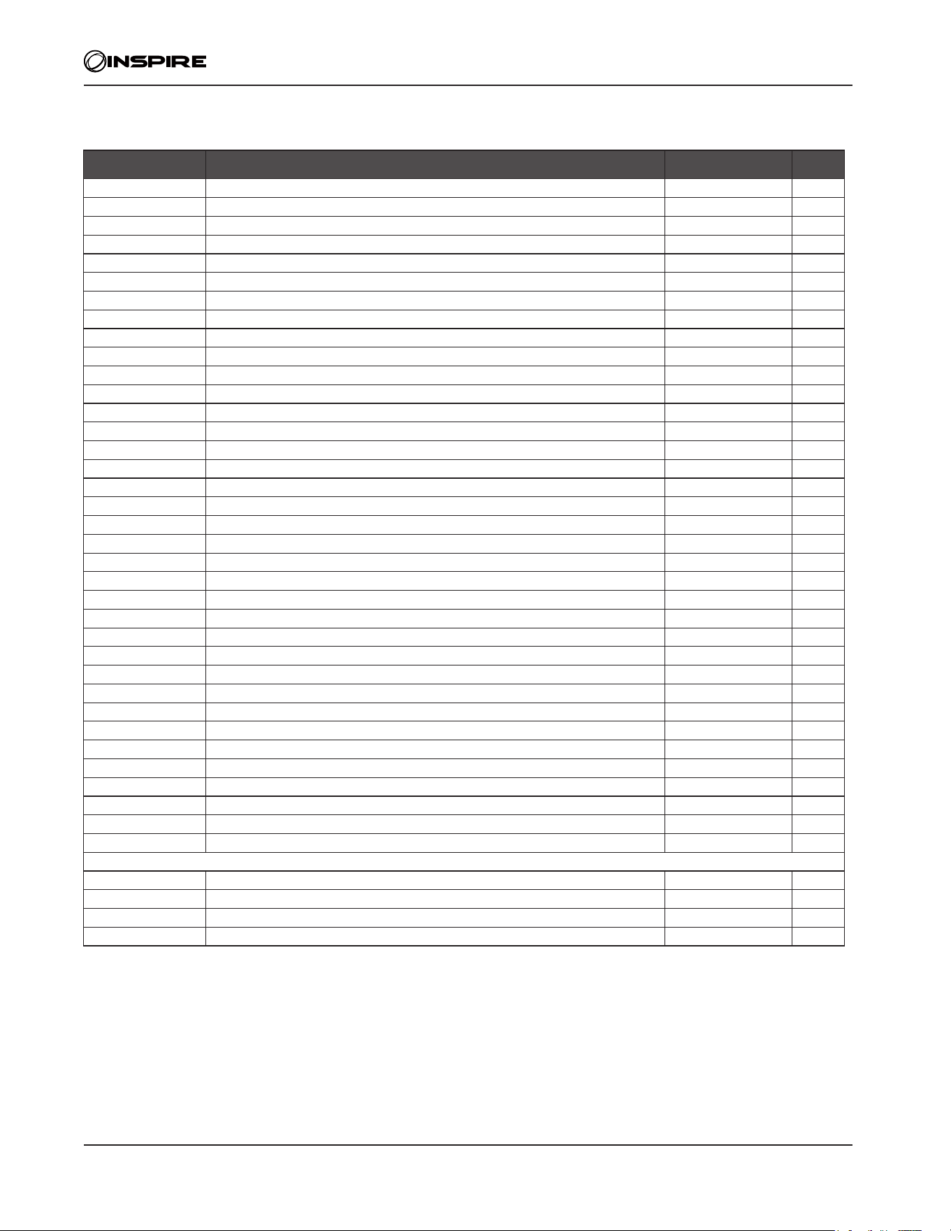
EXPLODED DIAGRAM
11
22
33
44
55
66
2525
2323
2121
77
77
88
99
1010
1111
1414
1212
1313
1717
1515
2222
1616
1818
1919
2525
1919
2525
1919
2525
1919
2525
1919
2525
1919
2525
1919
2525
1919
2525
2525
2424
2424
2525
2525
2525
2525
2323
2121
2020
2323
2525
2020
2323
2525
2020
2323
2525
2020
2323
2525
66
2525
2323
2121
2525
2323
2121
1313
1717
77
77
88
99
1010
1616
2222
1515
2525
2424
2424
2525
1818
2525
2525
2727
2828 2929 2929 3030
2626
2626
11
22
33
44
55
66
77
88
1515
99 1616
1010 1717
1111 1818
1212 1919
1313
2020
1414 2121
11
22
33
44
55
66
77
88
1515
99
1616
1010 1717
1111 1818
1212 1919
1313 2020
1414 2121
Pg. 16 80432-EN-V2025-02-14
PARTS LIST
No. Description Part Number Qty.
1
Right Station Assembly 100100 1
2
Left Station Assembly 100101 1
3
Upper Frame Assembly 100104 1
4
Lower Cross Brace 100102 1
5
Upper Cross Brace 100103 1
6
Guide Rod Bracket 100185 2
7
Guide rod 100122 4
8
Selector Stem Assembly 100183 2
9
Weight Selector Pin 100151 2
10
Weight Plate 100177 30
11
Rope 100172 1
12
Curl Bar 100184 1
13
Single Handle 100152 2
14
Chin Up Belt 100171 1
15
Height Adjustment Handle 100145 2
16
Rubber Bumper 100148 4
17
Hook 100174 2
18
M10×80 Allen Bolt 100187 4
19
M10×70 Allen Bolt 100188 8
20
M10×25 Allen Bolt 100189 4
21
M10×20 Allen Bolt 100190 4
22
M5×8 Allen Bolt 100191 2
23
#10 Lock Washer 100192 8
24
M10 Aircraft Nut 100193 8
25
#10 Washer 100194 24
26
Resistance Label Set 100178 2
27
Tablet Holder 100186 1
28
M6×75 Bolt 100195 1
29
#6 Washer 100196 2
30
M6 Nut 100197 1
31
Pulley Bracket 100110 2
32
Flat Washer Assembly 100115 2
33
Pulley 100173 2
34
Right Lock Switch 100108 1
35
Left Lock Switch 100109 1
36
M10×50 Allen Bolt 100201 2
Tool list
37
#6 Allen Wrench 100224 1
38
#5 Allen Wrench 100225 1
39
#4 Allen Wrench 100226 1
40
#10Wrench 100227 1