USER MANUAL
VERSION A3
April 15, 2025
Battery Shunt 300
RENOGY
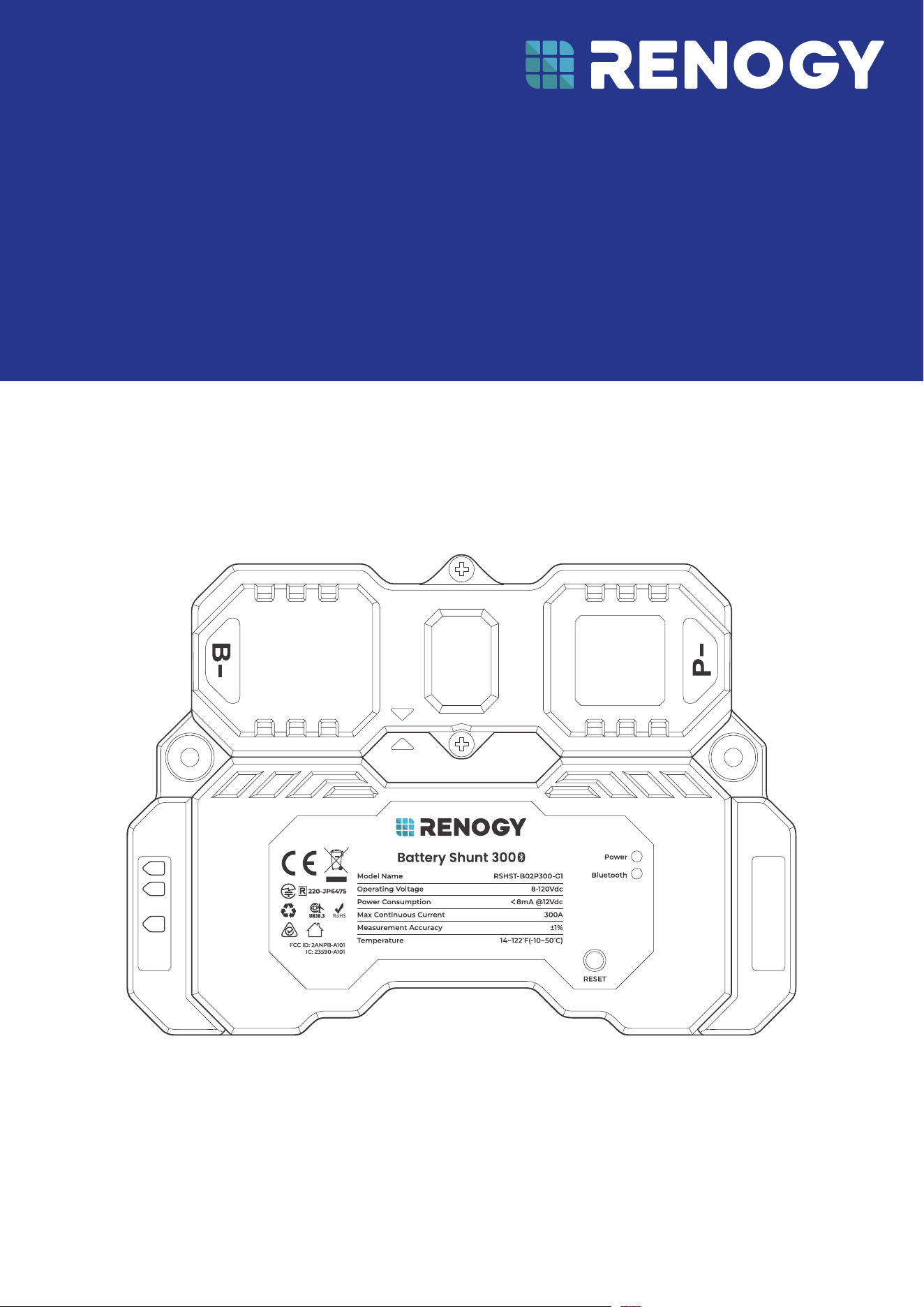
RSHST-B02P300-G1
B1
B2
T1
Before Getting Started
The user manual provides important operation and maintenance instructions for Renogy Battery Shunt
300 (hereinafter referred to as shunt).
Read the user manual carefully before operation and save it for future reference. Failure to observe the
instructions or precautions in the user manual can result in electrical shock, serious injury, or death, or
can damage the Renogy Battery Shunt, potentially rendering it inoperable.
z
Renogy ensures the accuracy, sufficiency, and the applicability of information in the user manual
at the time of printing due to continual product improvements that may occur.
z
Renogy assumes no responsibility or liability for personal and property losses, whether directly and
indirectly, caused by the user’s failure to install and use the product in compliance with the user
manual.
z
Renogy is not responsible or liable for failures, damages, or injuries resulting from repair attempted
by unqualified personnel, improper installation and operation.
z
The illustrations in the user manual are for demonstration purposes only. Details may appear
slightly different depending on product revision and market region.
z
Renogy reserves the right to change the information in the user manual without notice. For the
latest user manual, visit renogy.com.
Disclaimer
Renogy Battery Shunt 300 User Manual © 2025 Renogy. All rights reserved.
RENOGY
and
are registered trademarks of Renogy.
z
All information in the user manual is subject to copyright and other intellectual property rights of
Renogy and its licensors. The user manual may not be modified, reproduced, or copied, in whole or
in part, without the prior written permissions of Renogy and its licensors.
z
The registered trademarks in the user manual are the property of Renogy. The unauthorized use of
the trademarks is strictly prohibited.
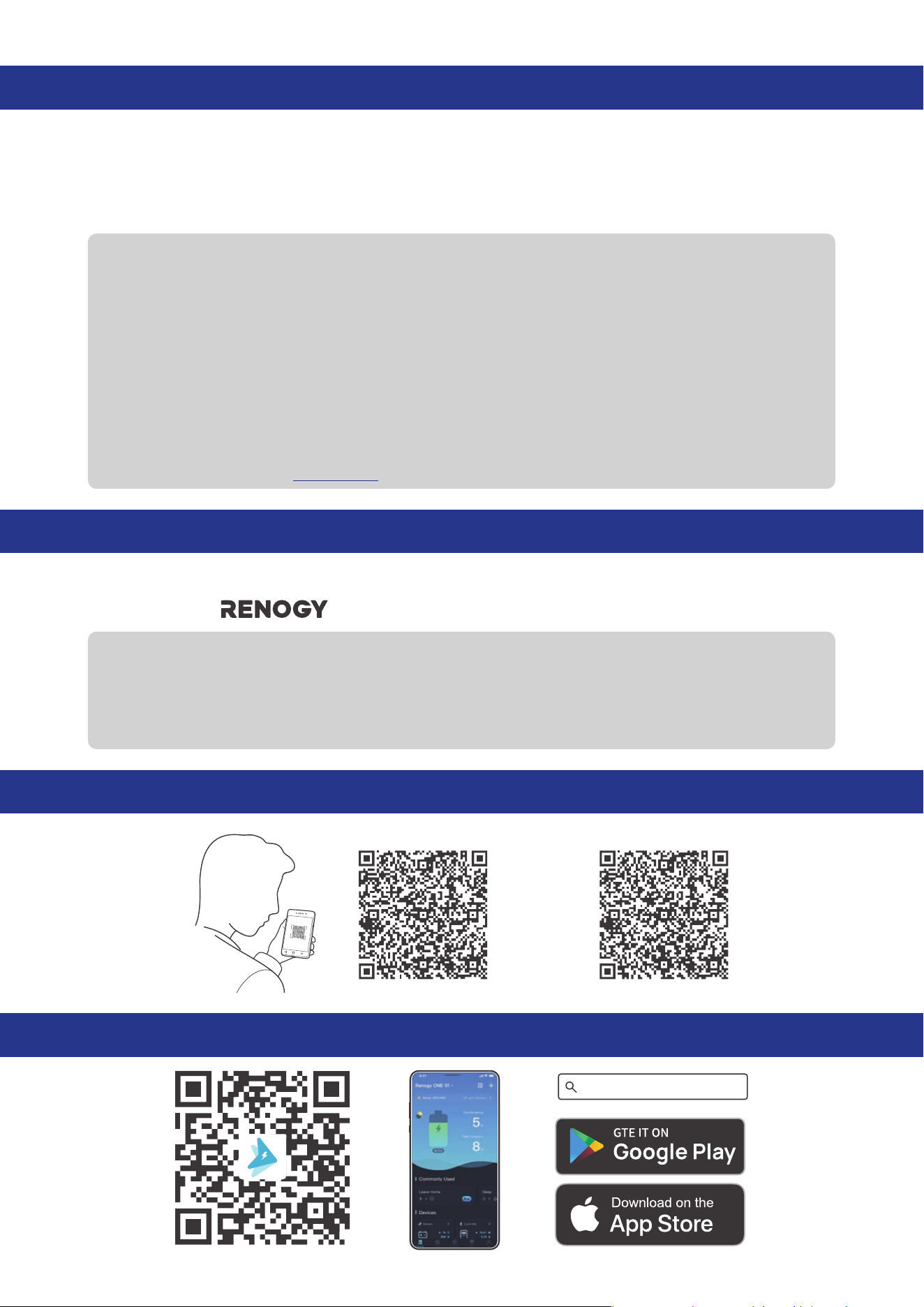
Online Manual
Quick Guide User Manual
Renogy App
Renogy App

1. General Information ........................................................................................................................... 1
1.1. Symbols Used .............................................................................................................................................. 1
1.2. Introduction .................................................................................................................................................1
1.3. Key Features ................................................................................................................................................1
1.4. SKU ................................................................................................................................................................. 1
2. Get to Know Renogy Battery Shunt 300 .......................................................................................... 2
2.1. What
’
s In the Box?
..................................................................................................................................... 2
2.2. Required Tools & Accessories.................................................................................................................. 2
2.3. Product Overview ....................................................................................................................................... 3
2.4. System Setup ............................................................................................................................................. 3
3. Preparation .........................................................................................................................................6
3.1. Plan a Mounting Site ................................................................................................................................. 6
3.2. Check Renogy Battery Shunt 300 .......................................................................................................... 6
3.3. Check System Voltage and Current ........................................................................................................7
3.4. Size Bare Wires ............................................................................................................................................7
3.5. How to Install 3/8 in Lugs? .......................................................................................................................7
4. Installation ..........................................................................................................................................9
4.1. Wear Insulating Gloves .............................................................................................................................. 9
4.2. Remove the Covers .................................................................................................................................... 9
4.3. Connect the Shunt to the Auxiliary Battery Negative .......................................................................10
4.4. Connect the Shunt to the Device AUX BAT- .......................................................................................10
4.5. Connect the Shunt to the Auxiliary Battery Positive......................................................................... 11
4.6. Install a Battery Temperature Sensor ................................................................................................... 11
4.7. Connect the Shunt to the Starter Battery Positive (Optional) ........................................................12
4.8. Mount the Shunt (Optional) ....................................................................................................................12
4.9. Install the Covers ......................................................................................................................................13
5. Configuration .................................................................................................................................... 14
5.1. Power On .....................................................................................................................................................14
5.2. Pairing with the Renogy App or Renogy ONE ......................................................................................14
5.3. Energy Monitoring.....................................................................................................................................16
5.4. SOC Synchronization ...............................................................................................................................18
5.5. Essential Alarm Settings ........................................................................................................................20
5.6. Historical Data .......................................................................................................................................... 22
5.7. Device Info .................................................................................................................................................23
6. LED Indicators ...................................................................................................................................24
7. Troubleshooting................................................................................................................................25
8. FAQ ......................................................................................................................................................26
Table of Contents

9. Dimensions and Specifications .......................................................................................................27
9.1. Dimensions ................................................................................................................................................ 27
9.2. Technical Specifications ......................................................................................................................... 27
10. Maintenance ......................................................................................................................................29
10.1. Inspection .................................................................................................................................................. 29
10.2. Cleaning .....................................................................................................................................................29
10.3. Storage .......................................................................................................................................................29
11. Emergency Responses .....................................................................................................................30
11.1. Fire ..............................................................................................................................................................30
11.2. Flooding .....................................................................................................................................................30
11.3. Smell ...........................................................................................................................................................30
11.4. Noise ...........................................................................................................................................................30
Renogy Support
........................................................................................................................................ 31
FCC & RSS
..................................................................................................................................................32
FCC Statement
....................................................................................................................................................32
FCC Radiation Exposure Statement
................................................................................................................32
RSS Standard
....................................................................................................................................................... 32
— 1 —
1. General Information
1.1. Symbols Used
The following symbols are used throughout the user manual to highlight important information.
WARNING: Indicates a potentially dangerous condition which could result in injury or death.
CAUTION: Indicates a critical procedure for safe and proper installation and operation.
NOTE: Indicates an important step or tip for optimal performance.
1.2. Introduction
Renogy Battery Shunt 300 is an intelligent battery monitor that measures the battery voltage and
current based on which it calculates the state of charge (SOC) and remaining running time of the
battery.
In addition, the shunt records historical charging and discharging data such as full deep discharge
cycle, discharge capacity, charge cycle, and battery temperature.
With the built-in Bluetooth module, Battery Shunt 300 communicates with the Renogy app and
Renogy ONE. This allows you to monitor real-time charging and discharging data and customize related
parameters. These settings encompass nominal capacity, deep discharge thresholds, temperature
alarms, and SOC alarms.
1.3. Key Features
z
Universal Battery Compatibility
Works seamlessly with various battery types, including Lead Acid (AGM, GEL), Lithium Iron Phosphate,
Lithium-ion, and Nickel-metal hybrid.
z
Comprehensive Battery Insights
Provides vital battery information such as State of Charge (SOC), voltage, current, energy, remaining
time, temperature, and starter battery voltage.
z
Alarm and Historical Data
Records historical data and offers alerts for abnormal conditions through the Renogy app.
z
Convenient Remote Monitoring
Enables remote monitoring and control via Renogy ONE and the Renogy App using Bluetooth
connectivity.
z
Effortless Installation and Configuration
Simplifies installation and settings adjustments through the Renogy app for a user-friendly
experience.
1.4. SKU
Renogy Battery Shunt 300 RSHST-B02P300-G1
— 2 —
2. Get to Know Renogy Battery Shunt 300
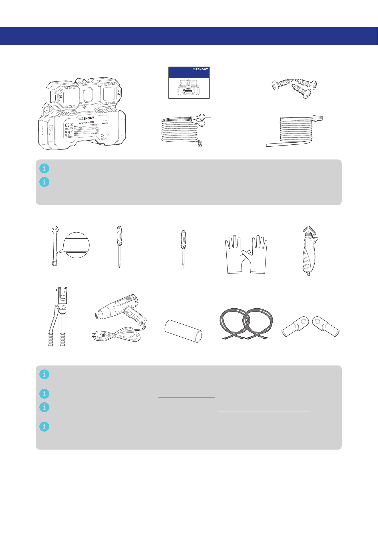
2.1. What’s In the Box?
VERSION A4
April 15, 2025
Battery Shunt 300
RENOGY
RSHST-B02P300-G1
QUICK GUIDE
B1
B2
T1
Renogy Battery Shunt 300 × 1
Quick Guide × 1
B1/B2 Wires (1 m) (22 AWG) × 2 Temperature Sensor (1.5 m) × 1
Mounting Screws x 3
(1 extra)
ST4 x 18 mm
3/8 in
(M10)
B1
B2
T1
Make sure that all accessories are complete and free of any signs of damage.
The accessories and product manual listed are crucial for the installation, excluding warranty
information and any additional items. Please note that the package contents may vary
depending on the specific product model.
2.2. Required Tools & Accessories
Insulating Gloves
Bare Wires × 2
Wrench
(11/16 in)
17 mm
17 mm
17 mm
Phillips
Screwdriver (#1)
Wire stripper
Slotted
Screwdriver (1 mm)
Manual Hydraulic
Pliers
3/8 in Lugs
(M10 Ring Terminals) × 2
Heat Gun Heat Shrink Tubing
Prior to installing and configuring the shunt, prepare the recommended tools, components, and
accessories.
For how to size bare wires, refer to “3.4. Size Bare Wires” in this manual.
For how to install 3/8 in Lugs (M10 Ring Terminals), see “3.5. How to Install 3/8 in Lugs?“ in this
manual.
For connection methods and required tools for the auxiliary battery, starter battery, and
equipment terminal, please refer to the user manual of the specific device. The diagrams
provided within this manual are for illustrative purposes only.
— 3 —
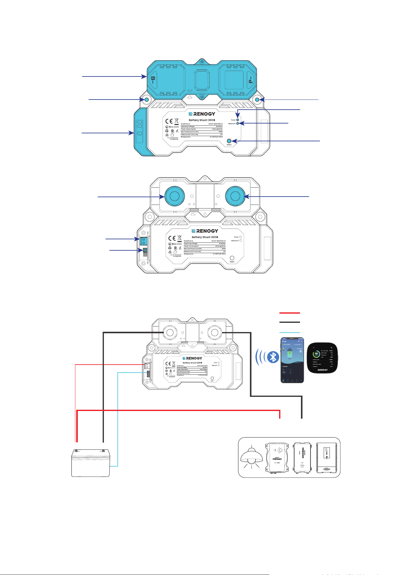
2.3. Product Overview
█
Exterior
Upper Cover
Lower Cover
Mounting Hole Mounting Hole
Power LED Indicator
Bluetooth LED Indicator
RESET Button
B1
B2
T1
█
Interior (with the covers removed)
B- Terminal (M10)
B1 and B2 Terminals
Battery Temperature
Sensor (T1) Port
P- Terminal (M10)
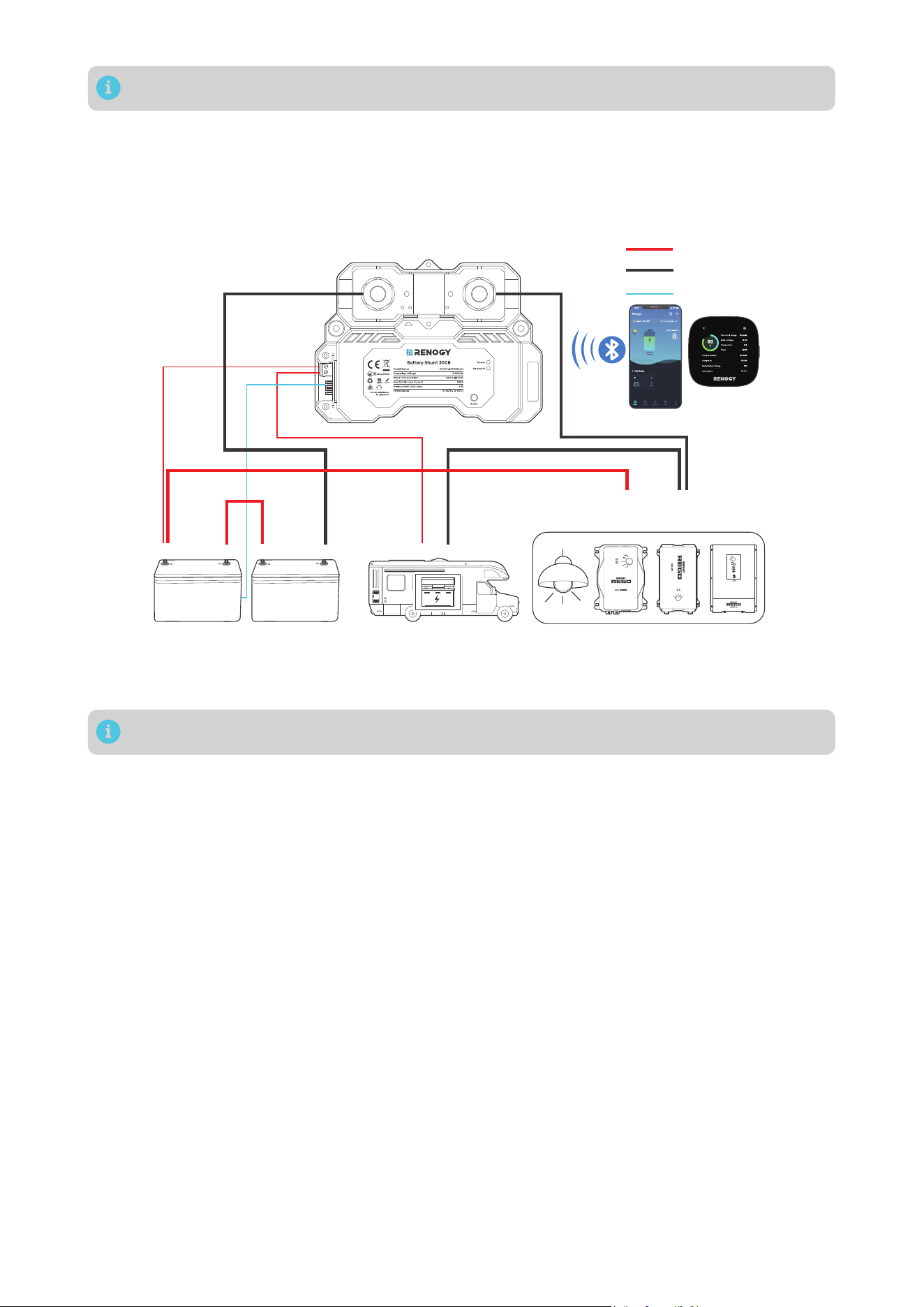
2.4. System Setup
█
Connecting to a Auxiliary Battery Only
Auxiliary Battery
Positive
+
-
Temperature
B-
B1
P-
Negative
Loads / Chargers / Inverters
AUX
BAT-
AUX
BAT+
DC-DC Battery Charger
-
+
T1
Shunt 300
Shunt 300
The AUX BAT+ and AUX BAT-
refer to the terminals of a specific
device through which the device
is connected to the positive and
negative terminals of an auxiliary
battery, respectively.
— 4 —
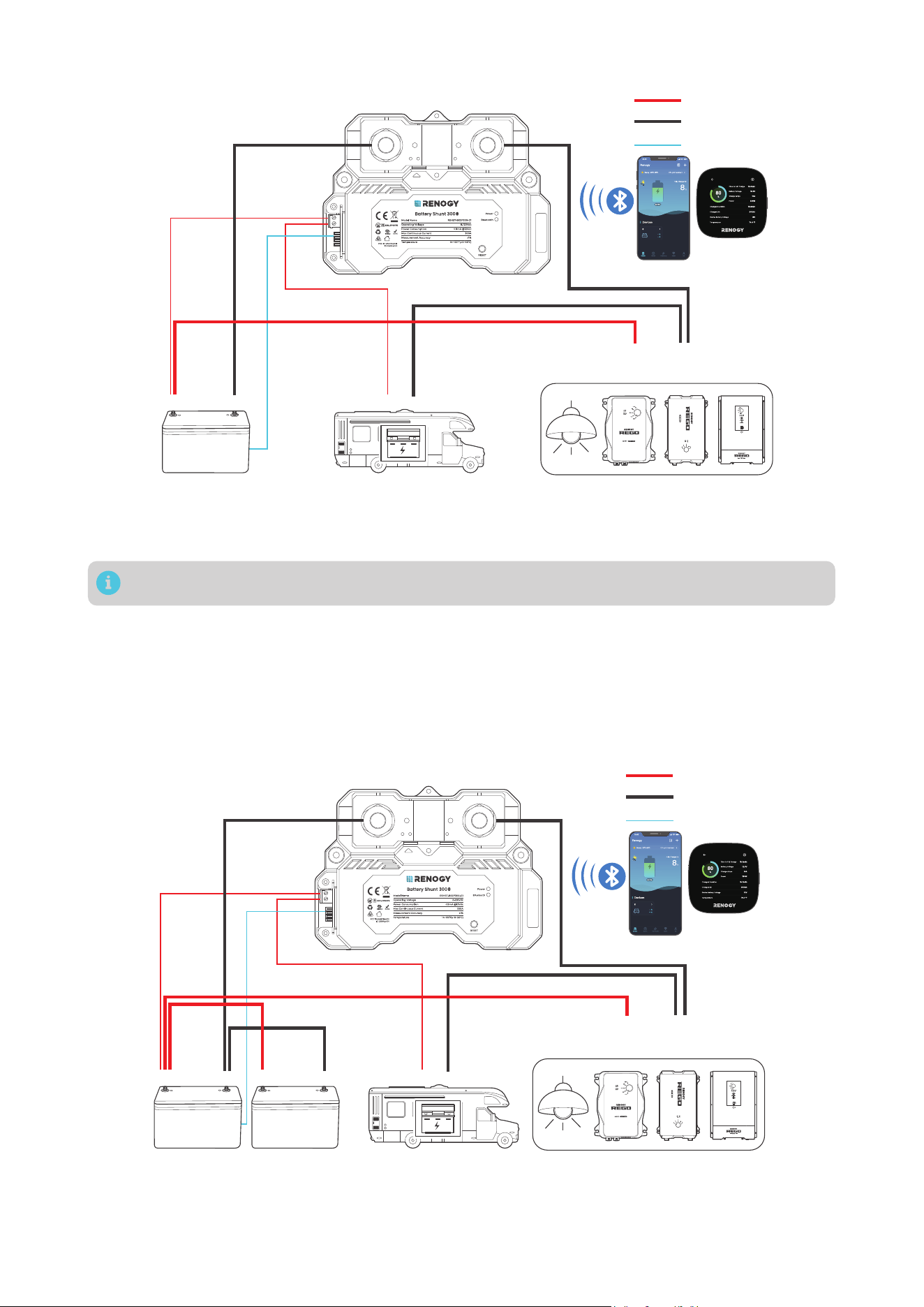
█
Connecting to Both a Auxiliary Battery and a Starter Battery
AUX
BAT-
AUX
BAT+
The AUX BAT+ and AUX BAT- refer to the terminals of a specific device through which the
device is connected to the positive and negative terminals of an auxiliary battery, respectively.
Shunt 300
Shunt 300
Auxiliary Battery
Positive
+
- -
+
Temperature
B-
B1
P-
Negative
Starter Battery
Loads / Chargers / Inverters
DC-DC Battery Charger
-
+
B2
T1
In such scenario, the shunt detects voltage of both the auxiliary battery and the starter battery.
█
Connecting to Multiple Auxiliary Batteries
The illustrations depict two batteries in parallel as an example. There is no limit on the number of
batteries in parallel. You can customize the setup with more batteries as needed.
Please ensure the combined continuous current from the batteries must not surpass 300A, maintaining
a voltage below 120V.
Auxiliary batteries in parallel
The
AUX BAT+ and AUX BAT- refer to the terminals of a specific device through which the
device is connected to the positive and negative terminals of an auxiliary battery, respectively.
AUX
BAT-
AUX
BAT+
Shunt 300
Shunt 300
Auxiliary Batteries
Positive
+
- -
+
Temperature
B-
B1
P-
Negative
Starter Battery (optional)
Loads / Chargers / Inverters
DC-DC Battery Charger
-
+
+
-
-
+
B2
T1
— 5 —
You can connect the Battery Shunt 300 to a starter battery via the B2 port on demand.
The illustrations depict two batteries in series as an example. There is no limit on the number of
batteries in series. You can customize the setup with more batteries as needed.
Please ensure the continuous current from the batteries must not surpass 300A, maintaining a total
voltage below 120V.
Auxiliary batteries in series
The
AUX BAT+ and AUX BAT- refer to the terminals of a specific device through which the
device is connected to the positive and negative terminals of an auxiliary battery, respectively.
AUX
BAT-
AUX
BAT+
Shunt 300
Shunt 300
Auxiliary Batteries
Positive
+
- -
+
Temperature
B-
B1
P-
Negative
Starter Battery (optional)
Loads / Chargers / Inverters
DC-DC Battery Charger
-
+
+
-
-
+
B2
T1
You can connect the Battery Shunt 300 to a starter battery via the B2 port on demand.
— 6 —
3. Preparation
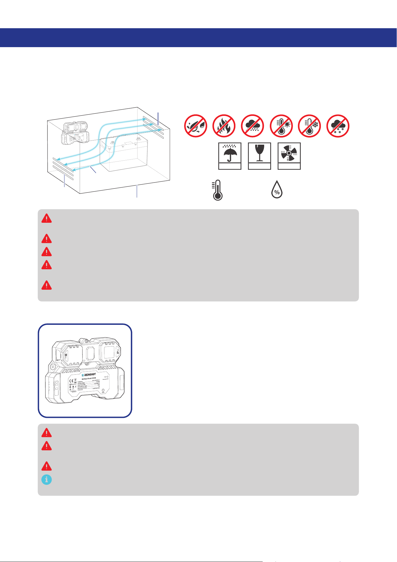
3.1. Plan a Mounting Site
Select a proper mounting site to ensure the shunt can be safely connected to the battery and other
necessary devices with the relevant cables. Install the shunt in a clean, cool, and dry location, free from
any accumulation of water, oil, or dirt. For optimal Bluetooth communication, avoid placing the battery
shunt near metal objects.
KEEP DRY FRAGILE VENTILATION
14°F to 122°F
-10°C to 50°C
0% to 95%
Enclosed space
Vent
Vent
Air
cross-flow
B1
B2
T1
Install the Renogy Battery Shunt 300 indoors and prevent its components from being exposed to
direct sunlight.
Do not expose Renogy Battery Shunt 300 to flammable or harsh chemicals or vapors.
Keep Renogy Battery Shunt 300 out of the reach of children.
Make sure that the Renogy Battery Shunt 300 is installed with ambient temperature range from
-4°F to 122°F or -20°C to 50°C.
Make sure that the Renogy Battery Shunt 300 is installed in an environment with relative
humidity between 0% and 95% and no condensation.
3.2. Check Renogy Battery Shunt 300
B1
B2
T1
Inspect the shunt for any visible damage including cracks, dents,
deformation, and other visible abnormalities. All connector contacts
shall be clean, dry, and free of dirt and corrosion.
Do not use Renogy Battery Shunt 300 if it appears to be damaged.
There are no serviceable parts in Renogy Battery Shunt 300. Do not open, dismantle, repair,
tamper with, or modify it.
Wear proper protective equipment and use insulated tools during installation.
Do not dispose of Renogy Battery Shunt 300 as household waste. Comply with local, state, and
federal laws and regulations and use recycling channels as required.
— 7 —
3.3. Check System Voltage and Current
8V to 120V
-
+
Ensure the battery shunt operates within a power system with a
maximum system voltage of 120V and a continuous current of up
to 300A. Exceeding these voltage and current limits may cause
damage to the shunt.
Risk of electric shock! Before installing the shunt, please turn off all devices within the system
and ensure there is no current flowing through the circuit.
3.4. Size Bare Wires
Select proper bare wires based on the ampacity in your power system. Refer to the table below for
copper cable ampacities with different gauge sizes.
Cable Gauge Size Ampacity Cable Gauge Size Ampacity
14 AWG (2.08 mm²) 35A 2 AWG (33.6 mm²) 190A
12 AWG (3.31 mm²) 40A 1 AWG (42.4 mm²) 220A
10 AWG (5.25 mm²) 55A 1/0 AWG (53.5 mm²) 260A
8 AWG (8.36 mm²) 80A 2/0 AWG (67.4 mm²) 300A
6 AWG (13.3 mm²) 105A 4/0 AWG (107 mm²) 405A
4 AWG (21.1 mm²) 140A
The above values are from the NEC Table 310.17 for copper cables rated at 194°F (90°C), operating
at an ambient temperature of no more than 86°F (30°C). Cables longer than 13 feet (4000 mm)
may require thicker gauge wires to prevent excessive voltage drop in undersized wiring.
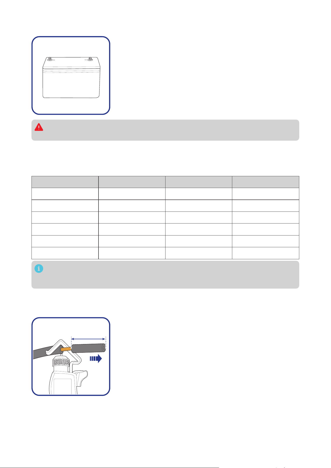
3.5. How to Install 3/8 in Lugs?
If a suitable battery tray cable isn’t available, you can customize one by following the steps below
:
0.4 in
(10 mm)
Step 1: Strip approximately 0.4 inches (10 mm) of insulation from
the end of a bare wire using a wire stripper.
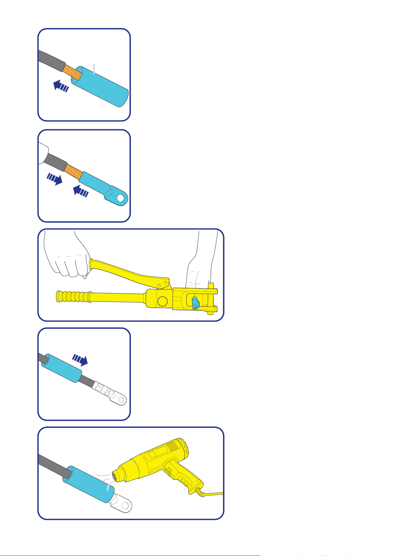
— 8 —
Heat
Shrink
Tubing
Step 2: Thread the exposed bare wire through a piece of heat shrink
tubing.
Step 3: Attach a 3/8-inch lug onto the end of the bare wire.
Step 4: Securely crimp the lug
onto the bare wire using a manual
hydraulic pliers.
Step 5: Slide the heat shrink tubing over the 3/8-inch lug.
Step 6: Apply heat to the heat shrink
tubing using a heat gun until it
shrinks and forms a tight seal.
— 9 —
4. Installation
To ensure safe and efficient operation of the battery shunt and to avoid potential damage or hazards,
always follow the installation instructions in the sequence described in this manual.
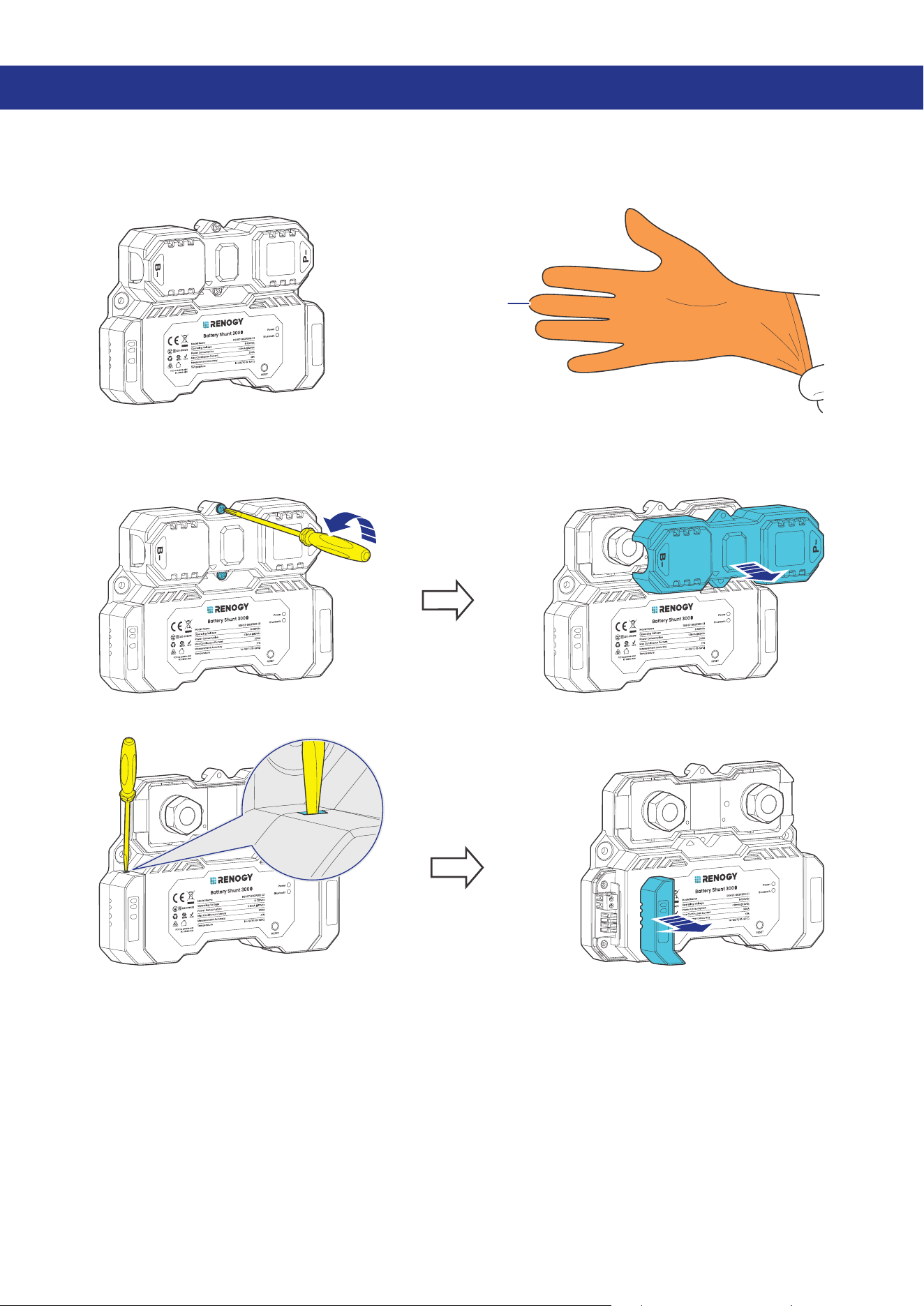
4.1. Wear Insulating Gloves
Insulating Gloves
B1
B2
T1
4.2. Remove the Covers
█
Remove the Upper Cover
B1
B2
T1
B1
B2
T1
█
Remove the Lower Cover
B1
B2
T1
B1
B2
T1
— 10 —
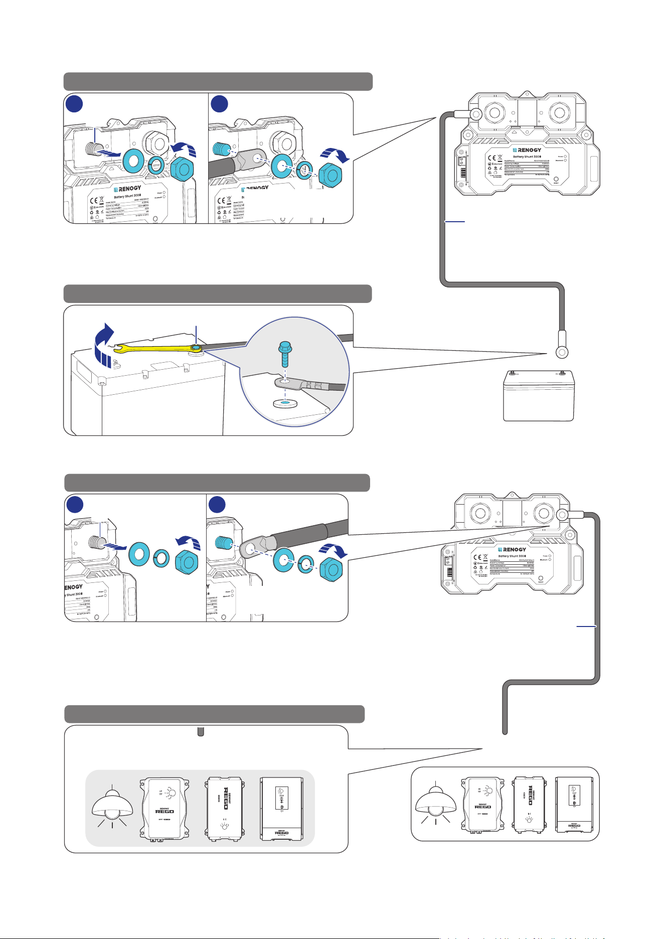
4.3. Connect the Shunt to the Auxiliary Battery Negative
173.5—224.8 in·lbs
(19.6—25.4 N·m)
-
-
+
Auxiliary Battery
STEP-1 Install the bare wire on the shunt B- terminal.
STEP-2 Install the bare wire on the battery negative.
Renogy Battery Shunt 300
Bare Wire
1 2
-
B-
B-
4.4. Connect the Shunt to the Device AUX BAT-
DC-DC Battery Charger
Loads & Charges & Inverters
AUX
BAT-
AUX
BAT-
DC-DC Battery Charger
STEP-1 Install the bare wire on the shunt P- terminal.
STEP-2 Install the bare wire on the device AUX BAT-.
Renogy Battery Shunt 300
Bare Wire
1
2
P-
P-
173.5—224.8 in·lbs
(19.6—25.4 N·m)
— 11 —
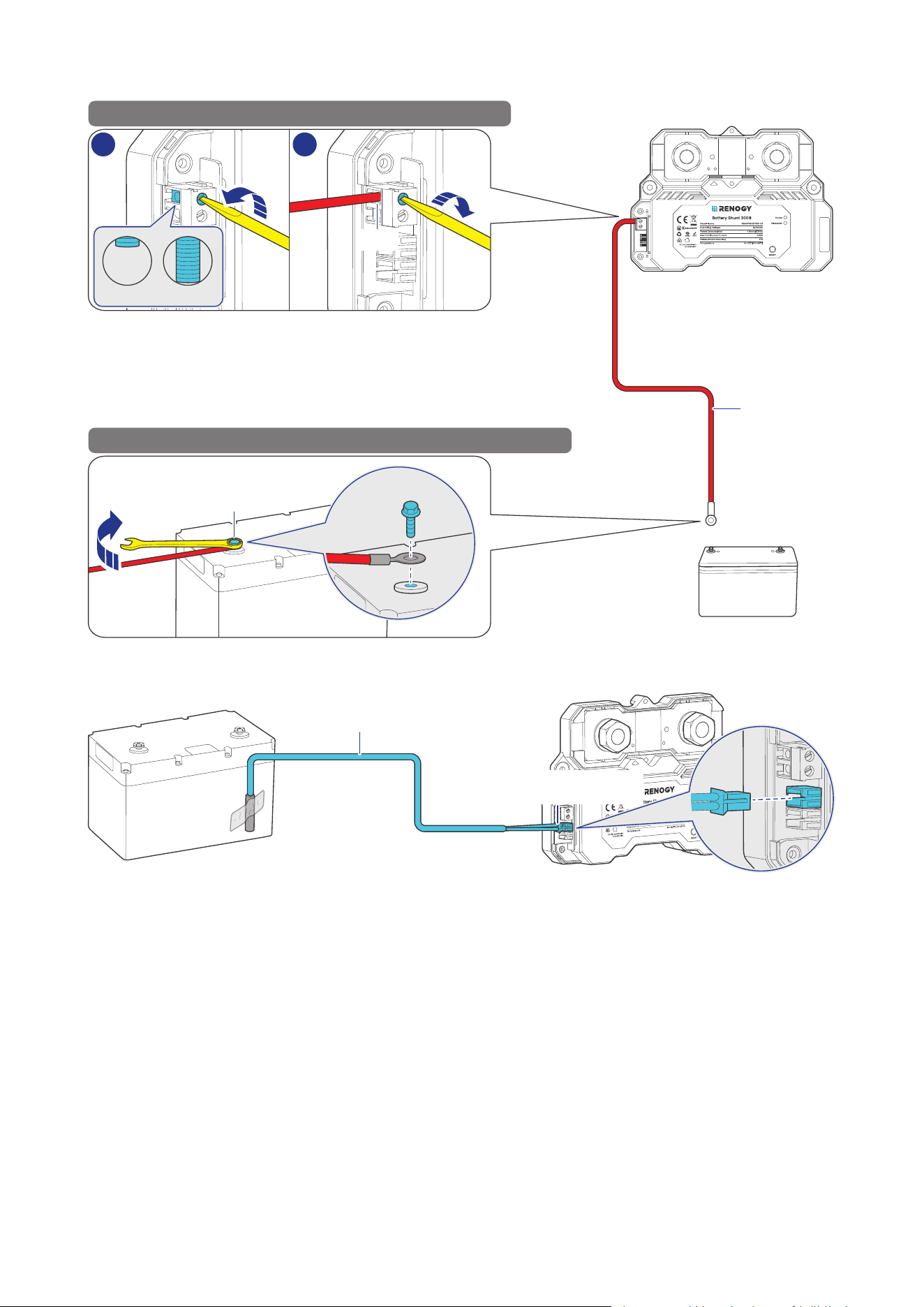
4.5. Connect the Shunt to the Auxiliary Battery Positive
+
+
-
+
Auxiliary Battery
STEP-1 Install the B+ wire on the shunt B1 terminal.
STEP-2 Install the B+ wire on the auxiliary battery positive.
Renogy Battery Shunt 300
B1 Wire
1 2
Open Close
B1
4.6. Install a Battery Temperature Sensor
Temperature Sensor
Battery Temperature
Sensor Port
— 12 —
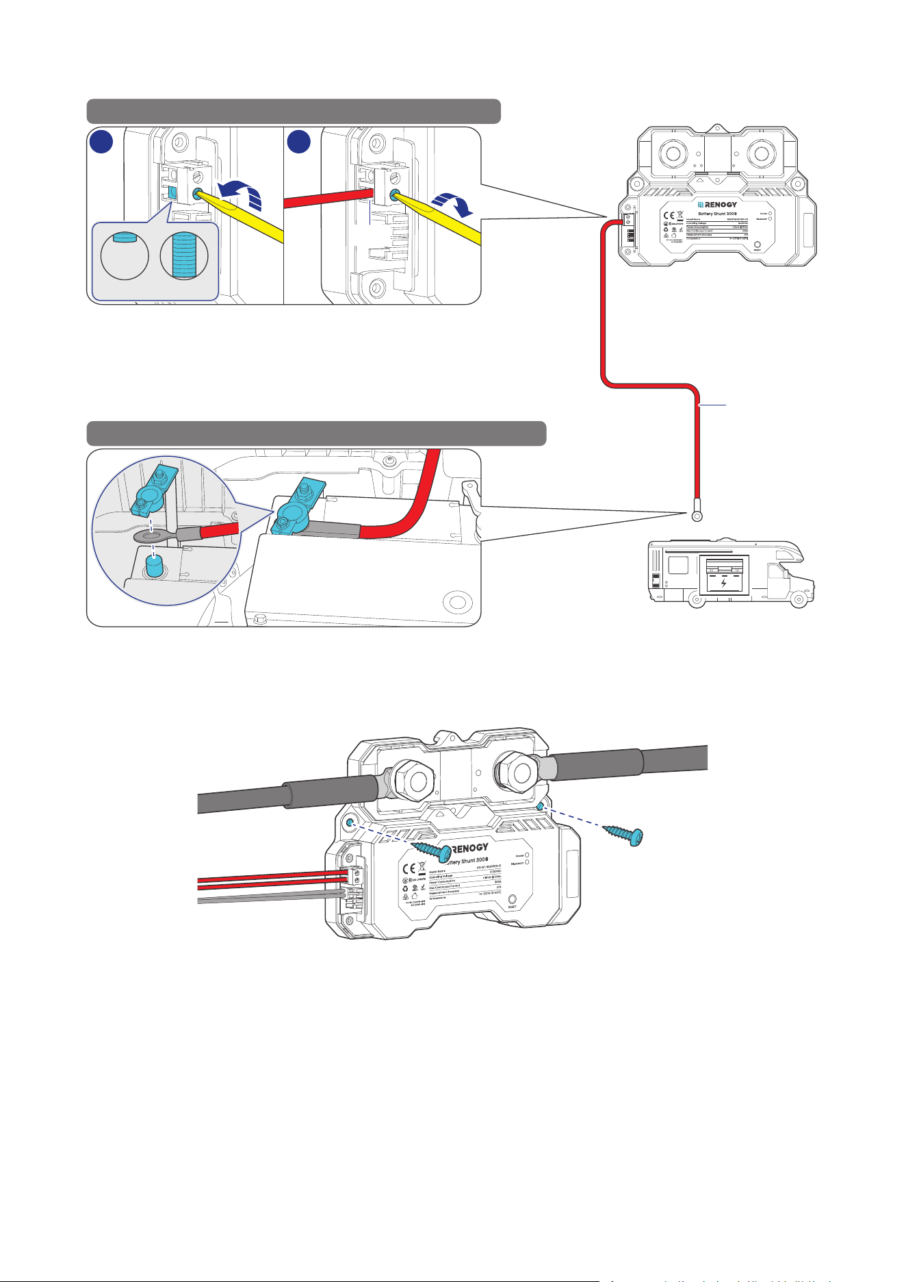
4.7. Connect the Shunt to the Starter Battery Positive (Optional)
+
+
Starter Battery
STEP-1 Install the B+ wire on the shunt B2 terminal.
STEP-2 Install the B+ wire on the starter battery positive.
Renogy Battery Shunt 300
B2 Wire
1
2
Open Close
B2
4.8. Mount the Shunt (Optional)
To guarantee system safety, mounting the shunt to a proper location is recommended. You can choose
a proper mounting site on demand.
— 13 —
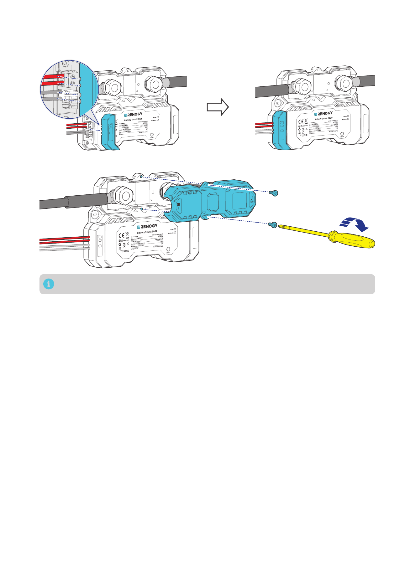
4.9. Install the Covers
█
Install the Lower Cover
B1
B2
T1
B1
B2
T1
█
Install the Upper Cover (Optional)
B1
B2
T1
Installing the Upper Cover is optional in cases where the terminals are not enclosed by the cover.
— 14 —
5. Configuration
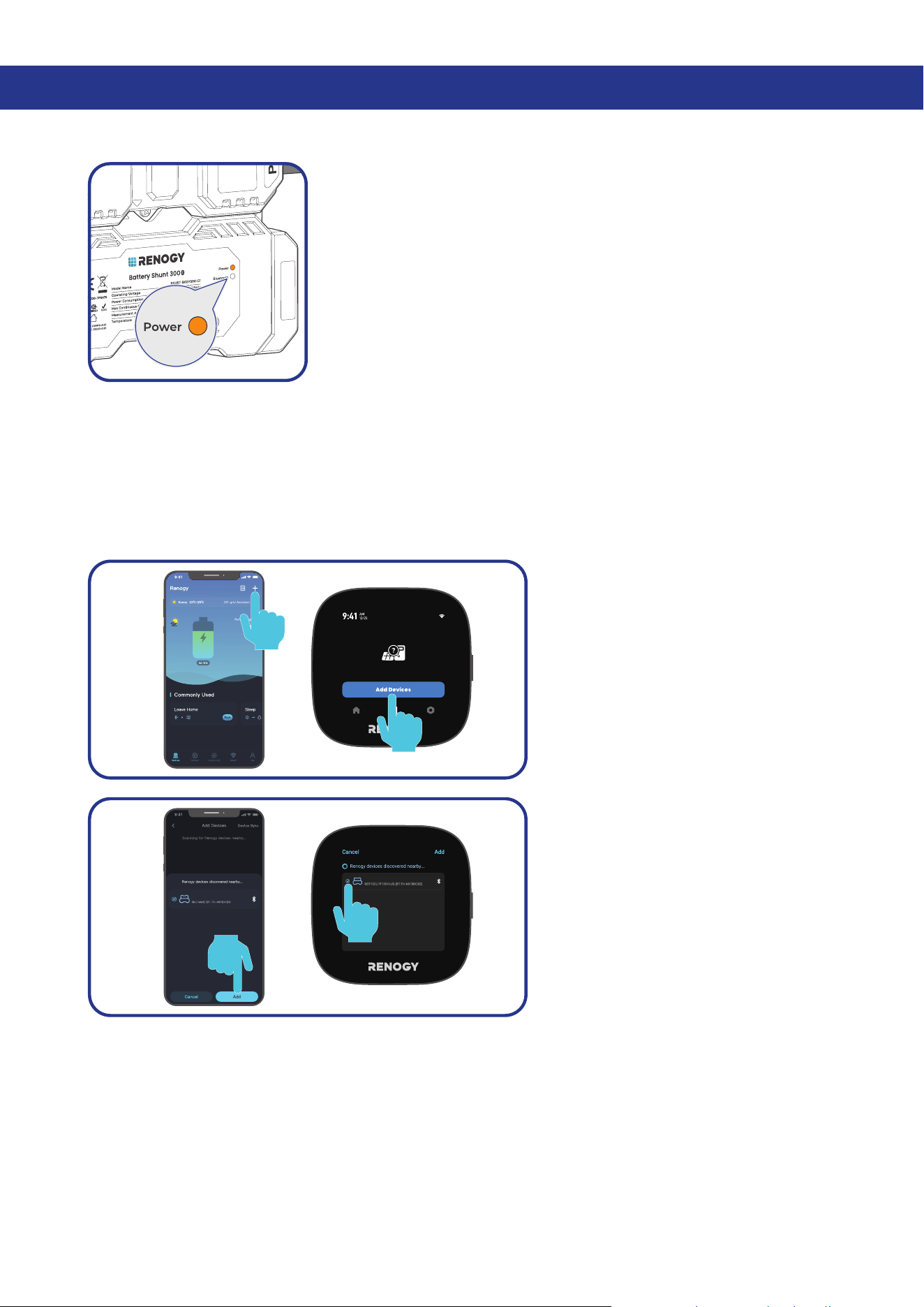
5.1. Power On
Power on all devices in your power system, and the Battery Shunt is
powered up automatically with the Power LED Indicator lighting up.
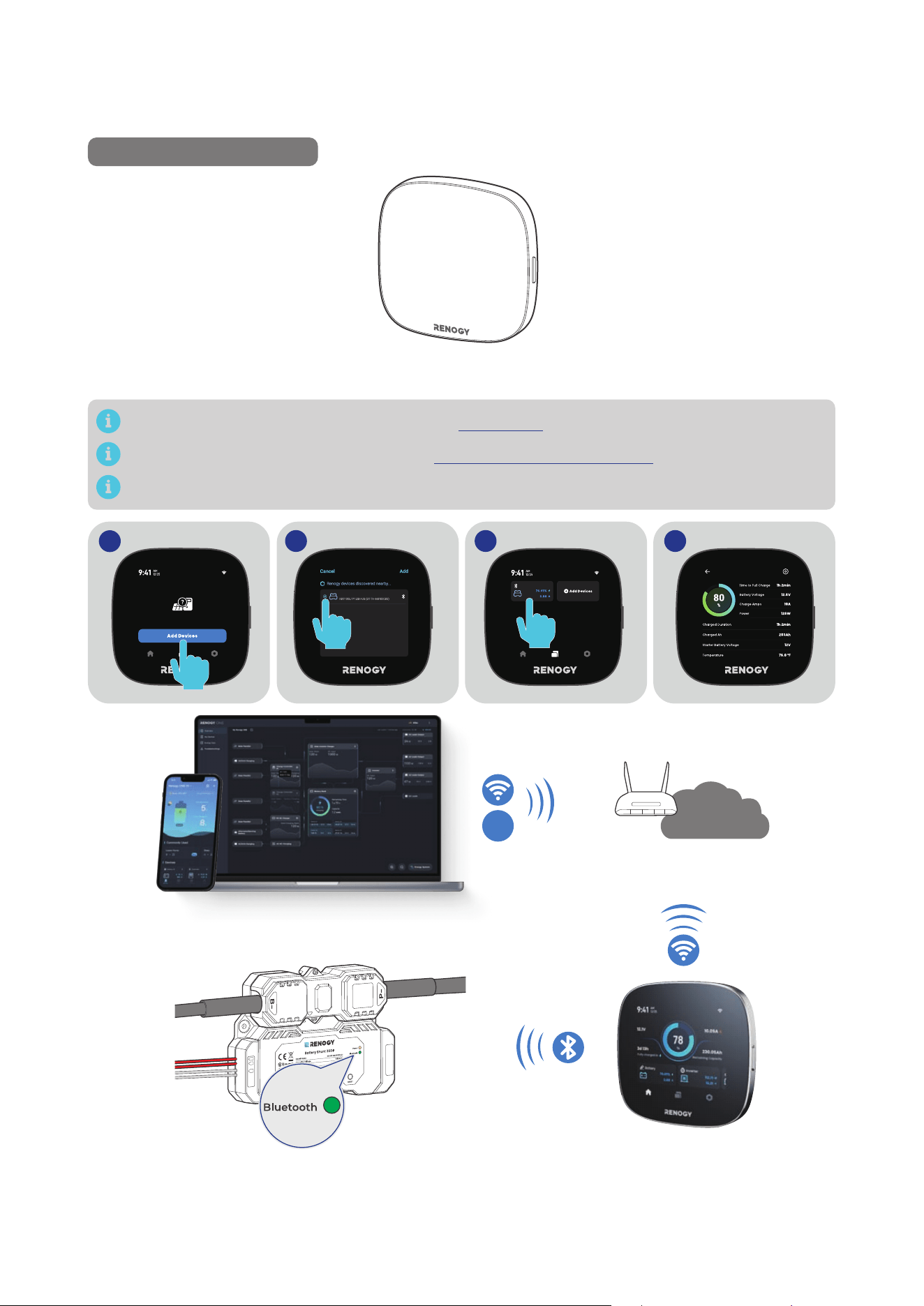
5.2. Pairing with the Renogy App or Renogy ONE
For initial use, set the “Rated Battery Ah” (rated battery capacity) on the app prior to other operations.
Rated Battery Ah should be the same as the rated capacity of the specific battery you use. For details,
refer to the battery user manual.
█
Initial Paring
For initial startup, follow the steps below to pair the shunt with the Renogy app or Renogy ONE.
Step 1: On Renogy or Renogy ONE,
navigate to “Add Devices”.
Shunt 300
Shunt 300
Step 2: Scan and pair the shunt with
the Renogy ONE or Renogy app.
— 15 —
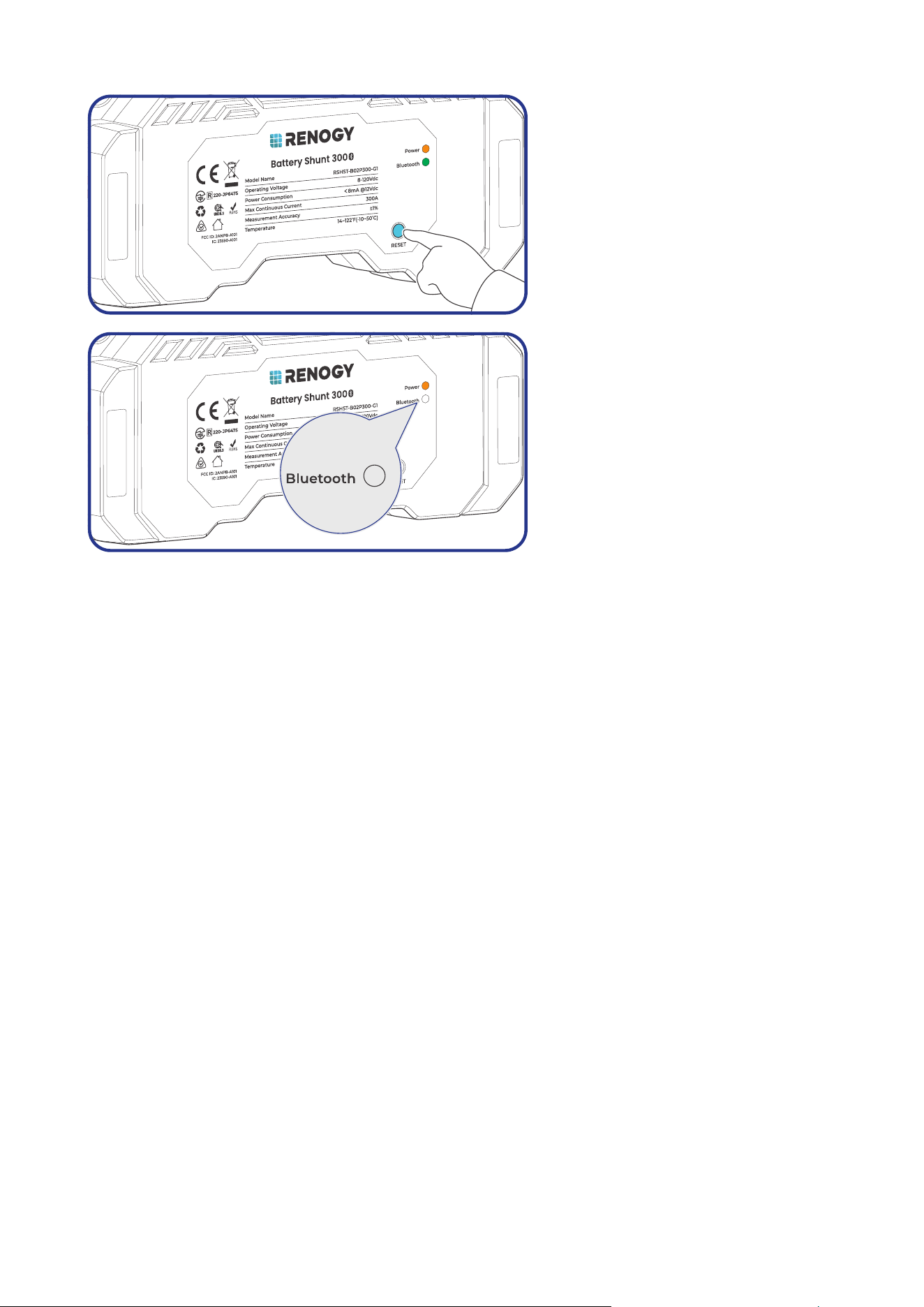
█
Pairing with Another Device
5s
Step 1: Remove the shunt from the
Renogy app or ONE. Alternatively,
you can press and hold RESET on the
shunt for 5s.
Step 2: After the Bluetooth LED turns
off, redo scanning and pairing.
— 16 —
5.3. Energy Monitoring
Depending on the specific application, the shunt can establish either short-range or long-range
communication connections with monitoring devices. These monitoring devices including RENOGY
ONE Core and the Renogy app facilitate real-time monitoring, programming, and complete system
management, offering comprehensive control and enhanced flexibility.
The version of the Renogy app might have been updated. Illustrations in the user manual are for
reference only. Follow the instructions based on the current app version.
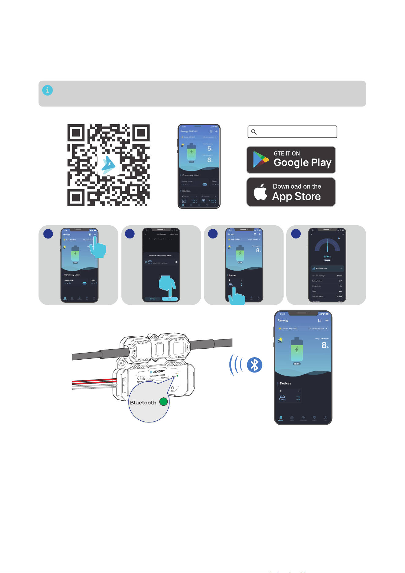
Download and login to the Renogy app.
Renogy App
█
Short-Range Monitoring via Renogy App
2 3 4
1
Shunt 300
Shunt 300
Shunt 300
On after
successful
pairing
B1
B2
T1
Shunt 300
— 17 —
█
Wireless Long-Range Monitoring
If long-range communication and programming are required, connect the shunt to RENOGY ONE Core
(sold separately) through Bluetooth, and the RENOGY ONE Core to the Renogy app through Wi-Fi.
Recommended Components
*RENOGY ONE Core
Components marked with “*” are available on renogy.com.
For instructions on Renogy ONE Core, see Renogy ONE Core User Manual.
Make sure the shunt does not communicate with any other device.
2 3 4
1
Shunt 300
Shunt 300
Shunt 300
On after
successful
pairing
B1
B2
T1
Internet
4G
— 18 —
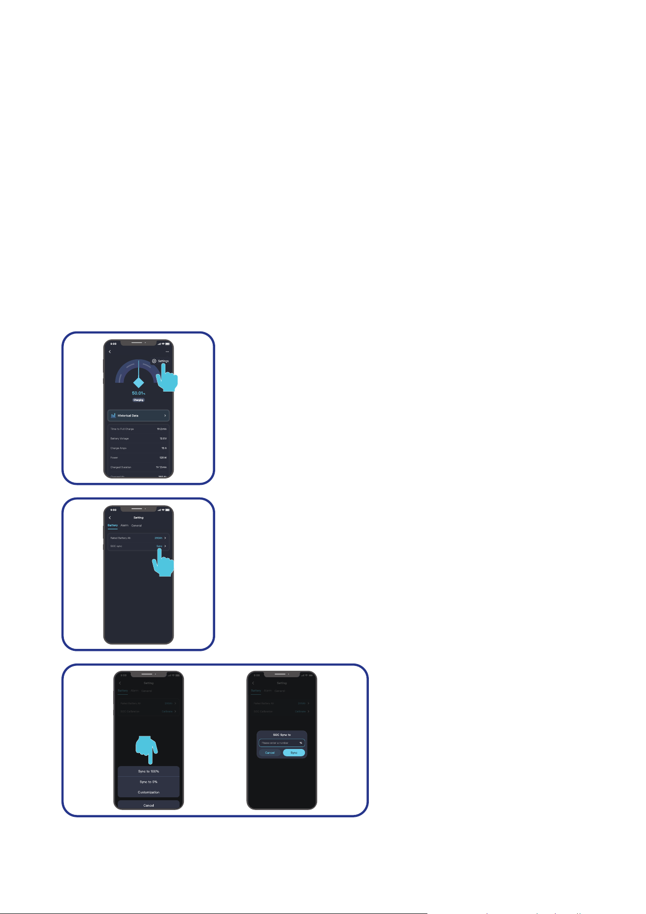
5.4. SOC Synchronization
To ensure reliable readout of the SOC of your battery, SOC synchronization is required, especially for
batteries that have been used for an extended period.
A battery’s capacity can degrade over time, so even if the battery may charge to full capacity, its actual
capacity might not be as high as when it was new. For instance, a new battery rated at a full capacity of
100Ah can only charges to 90Ah after a year of use. In this case, recalibrating the SOC is required, using
90Ah as the new reference point, rather than the original 100Ah.
SOC synchronization should be performed in the following scenarios:
z
During the initial shunt installation
z
After there has been an interruption in the voltage supply to the Renogy app or Renogy ONE
z
When the battery has not been fully charged
z
When the Renogy app or Renogy ONE has not detected that the battery has been fully charged
because the “Charging Amps” has been set incorrectly.
In this case, review the settings and make sure the battery regularly receives a full charge.
█
Renogy app
In the Renogy app, follow the steps below to synchronize the battery SOC in your system:
Shunt 300
Step 1: Tap the shunt details page. Tap "... > Settings" in the upper-
right corner of the page.
Step 2: Under “Battery”, tap Sync in “SOC sync”.
Step 3: You can choose “Sync to
100%”, “Sync to 0%”, “Customization”
or “Cancel”. It is recommended that
you customize the SOC to match the
actual SOC of your battery. Allowed
value ranges from 0 to 100.
— 19 —
Step 4: Tap “Sync” to complete the synchronization.
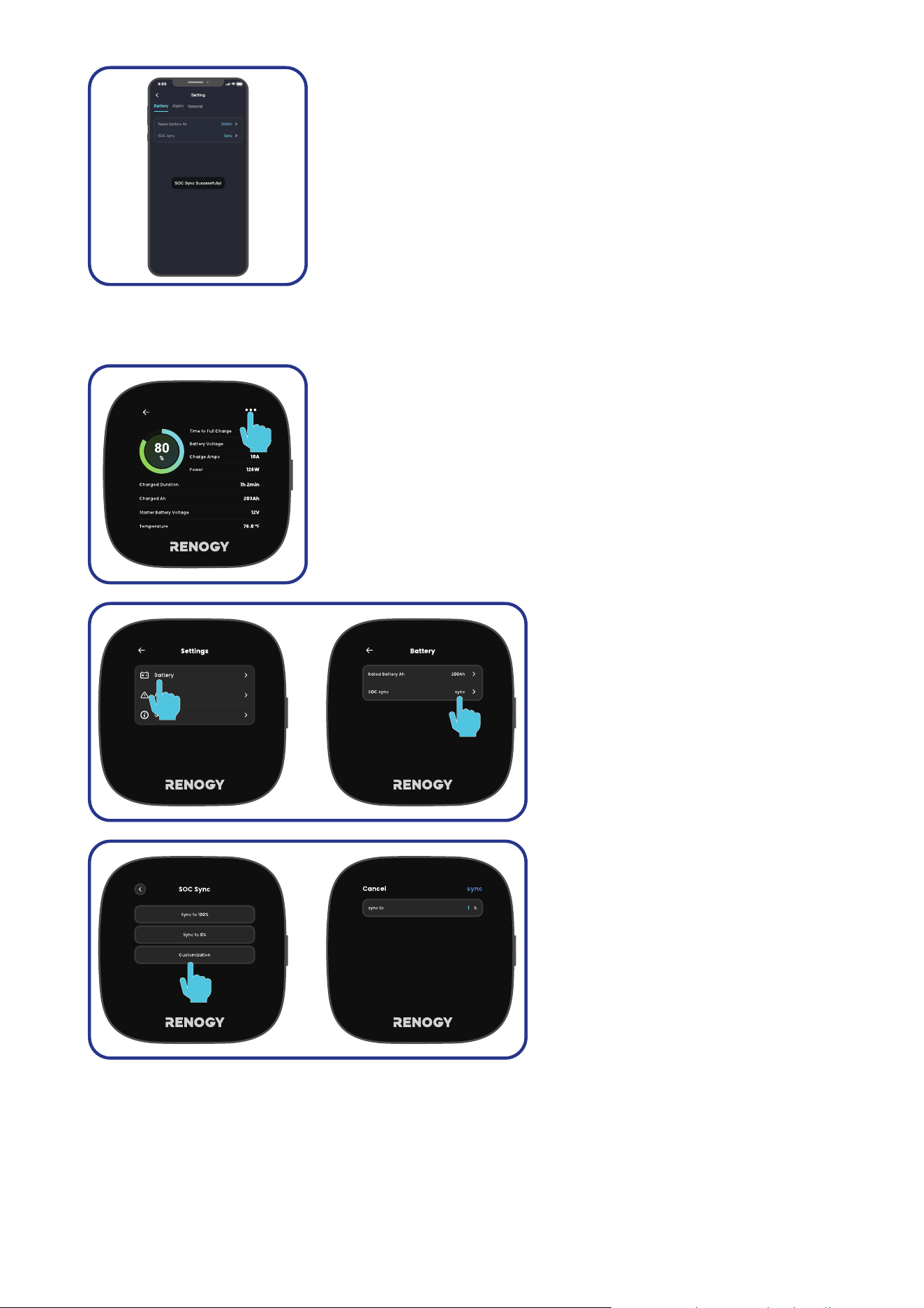
█
Renogy ONE
In Renogy ONE, follow the steps below to synchronize the battery SOC in your system:
Shunt 300
Step 1: Tap the shunt details page. Tap "..." in the upper-right corner
of the page.
Step 2: Under “Battery”, tap Sync in
“SOC sync”.
Step 3: You can choose “Sync to
100%”, “Sync to 0%”, “Customization”
or “Cancel”. It is recommended that
you customize the SOC to match the
actual SOC of your battery. Allowed
value ranges from 0 to 100.
— 20 —
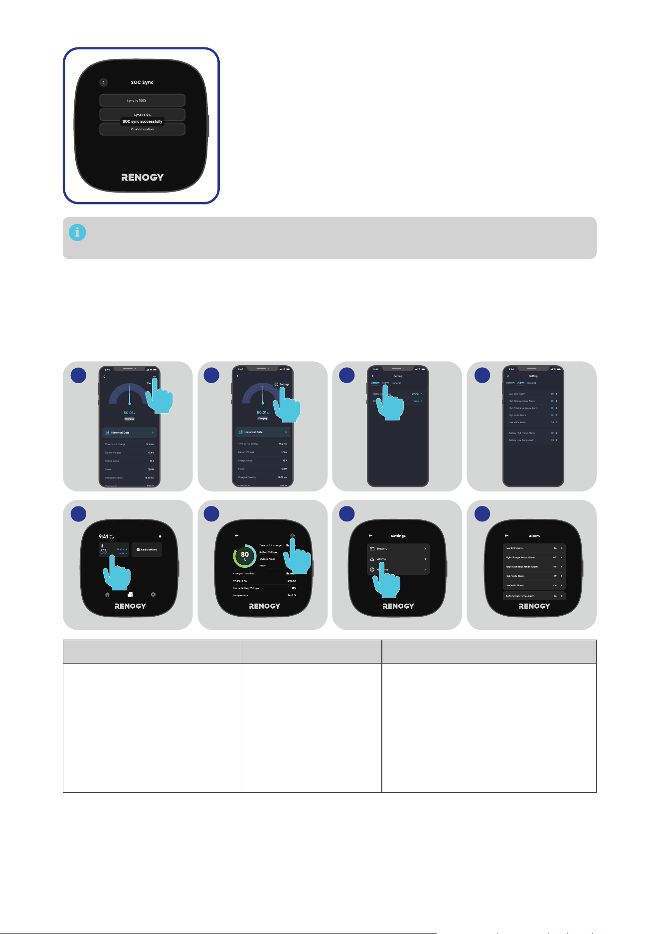
Step 4: Tap “Sync” to complete the synchronization.
The version of the Renogy app and Renogy ONE might have been updated. Illustrations in the
user manual are for reference only. Follow the instructions based on the current app version.
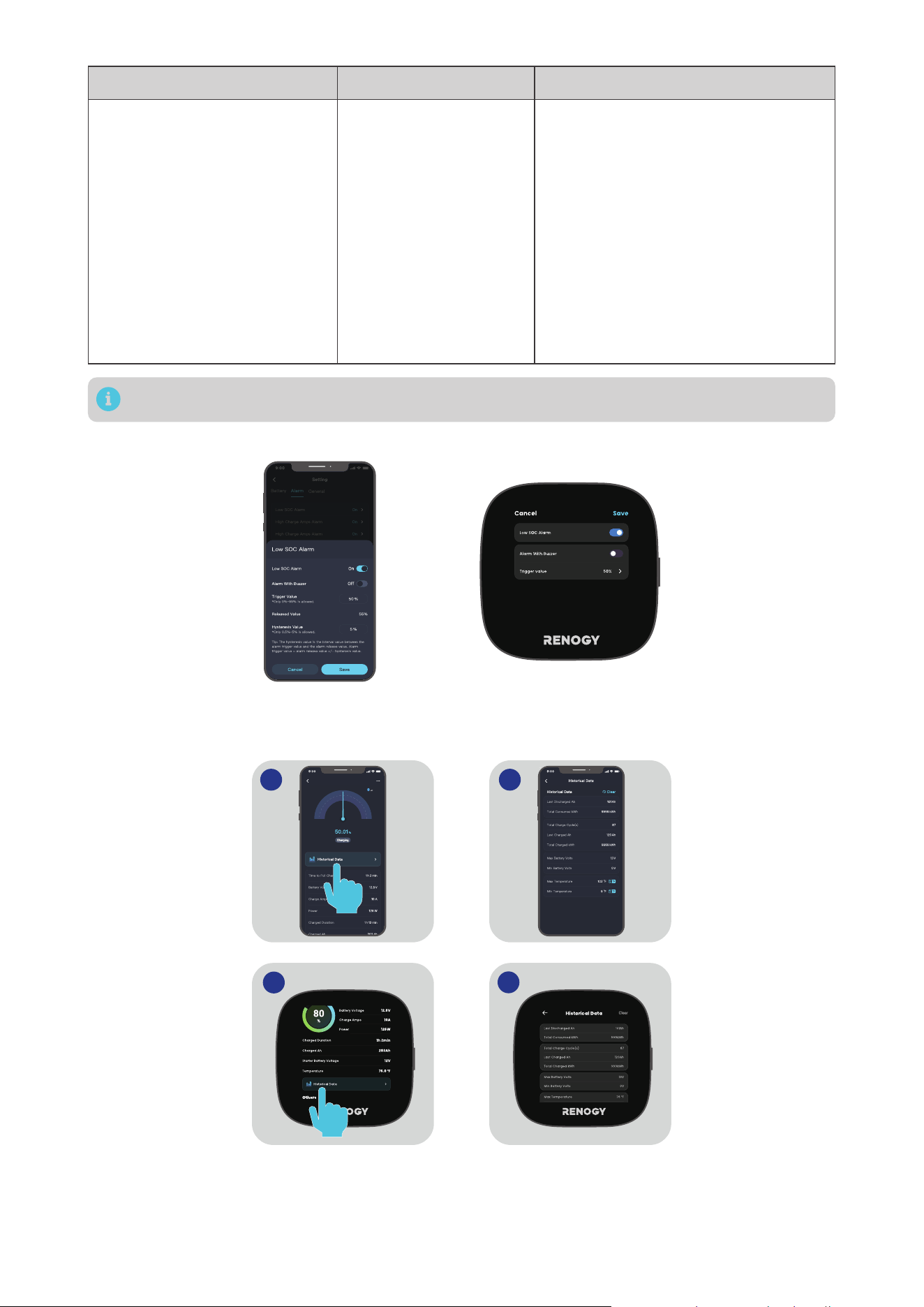
5.5. Essential Alarm Settings
The battery shunt provides diverse alarms to protect your battery from high temperature or voltage.
Most settings can stay their factory default, but you can customize them to better serve your needs.
On Renogy app or Renogy ONE Core, go to "... > Settings > Alarm" to configure essential alarms listed in
the table below.
2 3 4
1
Shunt 300 Shunt 300
2 3 4
1
Shunt 300
Shunt 300
Alarm Value Description
Low SOC Alarm
Range: 0% to 99%
z
Default trigger value:
50%.
z
Default release value:
55%
The Low SOC Alarm activates when
the battery SOC falls below the
designated “Trigger Value” threshold
and deactivates when the battery SOC
surpasses the Release Value.
Release Value = Trigger Value +
Hysteresis Value
Hysteresis value range: 0.5% to 5%

— 21 —
Alarm Value Description
High Volts Alarm
Range: 0V to 100V
Default High Volts Alarm
values vary depending on
the connected battery.
z
For 12V batteries:
14.4V
z
For 24V batteries:
28.8V
z
For 48V batteries:
57.6V
The High Volts Alarm activates when
the battery voltage reaches the
designated “Trigger Value” threshold
and deactivates when the battery
voltage drops below the Release Value.
Release Value = Trigger Value -
Hysteresis Value
Hysteresis value range: 0.2V to 5V
*The hysteresis value should be
consistent with that in Low Volts Alarm.
Low Volts Alarm
Range: 0V to 100V
Default Low Volts Alarm
values vary depending on
the connected battery.
z
For 12V batteries:
11.2V
z
For 24V batteries:
22.4V
z
For 48V batteries:
44.8V
The Low Volts Alarm activates when the
battery voltage reaches the designated
“Trigger Value” threshold and
deactivates when the battery voltage
rises above the Release Value.
Release Value = Trigger Value +
Hysteresis Value
Hysteresis value range: 0.2V to 5V
*The hysteresis value should be
consistent with that in High Volts Alarm.
High Charge Amps Alarm
Range: 1A to 300A
z
Default trigger value:
100A
z
Default release value:
95A
The High Charge Amps Alarm activates
when the battery charge current rises
above the designated “Trigger Value”
threshold and deactivates when the
charge current drops below the Release
Value.
Release Value = Trigger Value -
Hysteresis Value
Hysteresis value range: 1A to 5A
High Discharge Amps Alarm
Range: 1A to 300A
z
Default trigger value:
300A
z
Default release value:
295A
The High Discharge Amps Alarm
activates when the battery discharge
current rises above the designated
“Trigger Value” threshold and
deactivates when the discharge current
drops below the Release Value.
Release Value = Trigger Value -
Hysteresis Value
Hysteresis value range: 1A to 5A
Battery Low Temp Alarm
Range: -10°C to 60°C
(14°F to 140°F)
z
Default trigger value:
-10°C (14°F)
z
Default release value:
-5°C (23°F)
The Battery Low Temp Alarm activates
when the battery temperature drops
below the designated “Trigger Value”
threshold and deactivates when the
battery temperature rises above the
Release Value.
Release Value = Trigger Value +
Hysteresis Value
Hysteresis value range: 1°C to 5°C
*The hysteresis value should be
consistent with that in Battery High
Temp Alarm.
— 22 —
Alarm Value Description
Battery High Temp Alarm
Range: -10°C to 60°C
(14°F to 140°F)
z
Default trigger value:
55°C (131°F)
z
Default release value:
50°C (122°F)
The Battery High Temp Alarm activates
when the battery temperature rises
above the designated “Trigger Value”
threshold and deactivates when the
battery temperature drops below the
Release Value.
Release Value = Trigger Value -
Hysteresis Value
Hysteresis value range: 1°C to 5°C
*The hysteresis value should be
consistent with that in Battery Low
Temp Alarm.
The value ranges listed in the Renogy app or Renogy ONE Core prevail.
For each alarm, you can choose to either enable or disable the Buzzer when the alarm is triggered.
5.6. Historical Data
You can access the historical data of the connected battery via Renogy app or Renogy ONE Core
.
21
2
1
Shunt 300
The following two parameters should be explained:
z
Last Discharged Ah: This value represents the amount of electrical charge (in ampere-hours)
that was consumed or discharged from the battery in the last discharge cycle. It is calculated by
multiplying the discharge current (in amperes) by the duration of the discharge (in hours).
— 23 —
z
Last Charged Ah: This value represents the amount of electrical charge (in ampere-hours) that was
added or charged into the battery during the last charging cycle. It is calculated by multiplying the
charge current (in amperes) by the duration of the charge (in hours).
Maintaining historical data is essential for diagnosing potential battery issues. Avoid clearing the
history unless replacing the battery to preserve valuable information about its performance and
behavior over time.
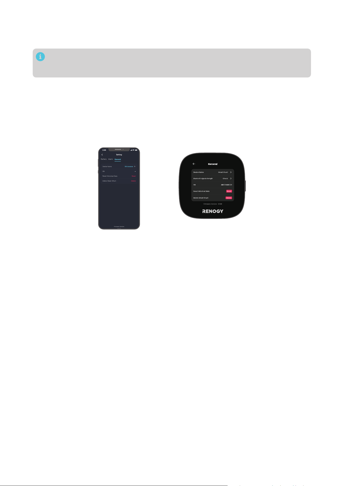
5.7. Device Info
In "... > Settings", navigate to "General" where you can:
z
Change the display name of your battery shunt
z
Access the SN of your battery shunt
z
Delete your battery shunt from Renogy ONE
z
Reset your historical data.
— 24 —
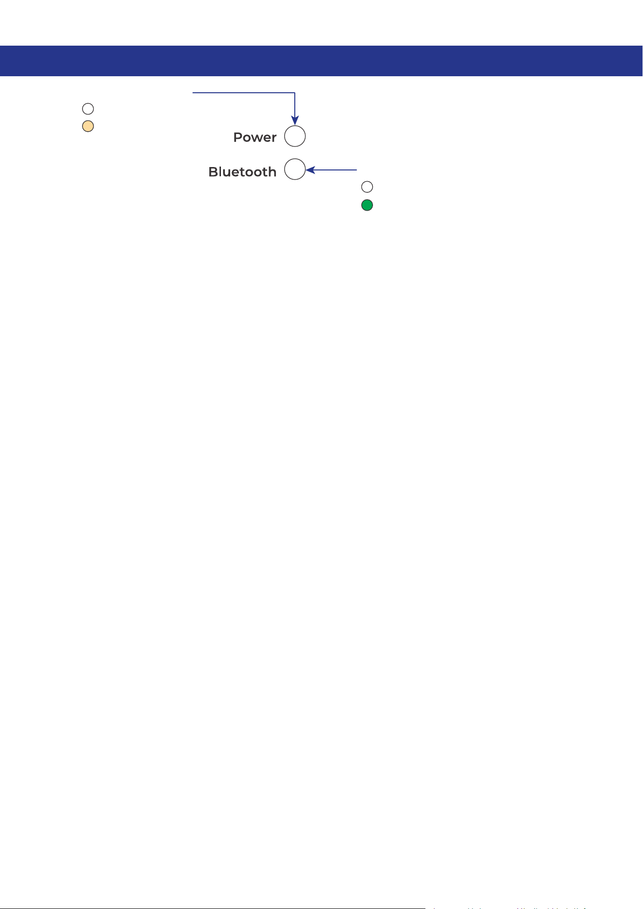
6. LED Indicators
Power LED Indicator
O: Power O
Solid: Power On
Bluetooth LED Indicator
O:
No Bluetooth device connected
Solid:
Bluetooth connected

— 25 —
7. Troubleshooting
Issue Possible Cause Solution
In the Renogy app or Renogy
ONE, the current is shown as
negative when charging and
positive when discharging.
Reverse polarity contact
Inspect for reverse contact on B-
or P- terminals.
Incorrect temperature
reading
The temperature sensor wiring is
loose
.
Confirm the Battery Temperature
Sensor is properly installed.
Incorrect SOC reading
The battery capacity decreases
as the charging and discharging
cycles increase.
Re-configure the “Rated Battery
Ah” to the capacity when the
battery is fully charged.
Inaccurate sampling precision
in large-current scenarios
Elevated ambient temperatures
can affect sampling accuracy.
Ensure proper ventilation for
the shunt and remove the upper
cover if needed.
Abnormal current reading
PFC circuit abnormality or loose
terminal connections
Remove the upper cover
from the shunt, and check
for abnormality on the PFC
flexible circuit or loose terminal
connections.

— 26 —
8. FAQ
█
What types of battery does the shunt work with?
Battery Shunt 300 works with all types of batteries and battery banks between 8V and 120V, providing
the settings are calibrated correctly.
█
Can I monitor more than two batteries in parallel and series with one Battery Shunt 300?
Yes, you can monitor more than two batteries in parallel and series with one Renogy Battery Shunt 300.
Just ensure that the total system voltage and maximum current draw are within the specified limits,
and follow the installation instructions accordingly.
█
What is the maximum operational current for the battery shunt?
The maximum continuous current for the Battery Shunt is 300A, with a maximum peak current of 500A.
Prolonged operation at currents exceeding 300A may lead to device overheating and damage, with a
serious risk of fire. It is crucial to use the device within the specified specifications.
█
Why is the SOC or Time Remaining reading inaccurate?
First, check if the wiring is correctly installed according to the guidelines. If the reading is still inaccurate,
you may need to reset the calibration. Charge the battery to 100%, and then recalibrate the battery
capacity data through the Renogy ONE or Renogy app (for details, see “5.4 SOC Synchronization”). This
process should help ensure more accurate readings.
For more FAQ, visit www.renogy.com/support/faq.
— 27 —
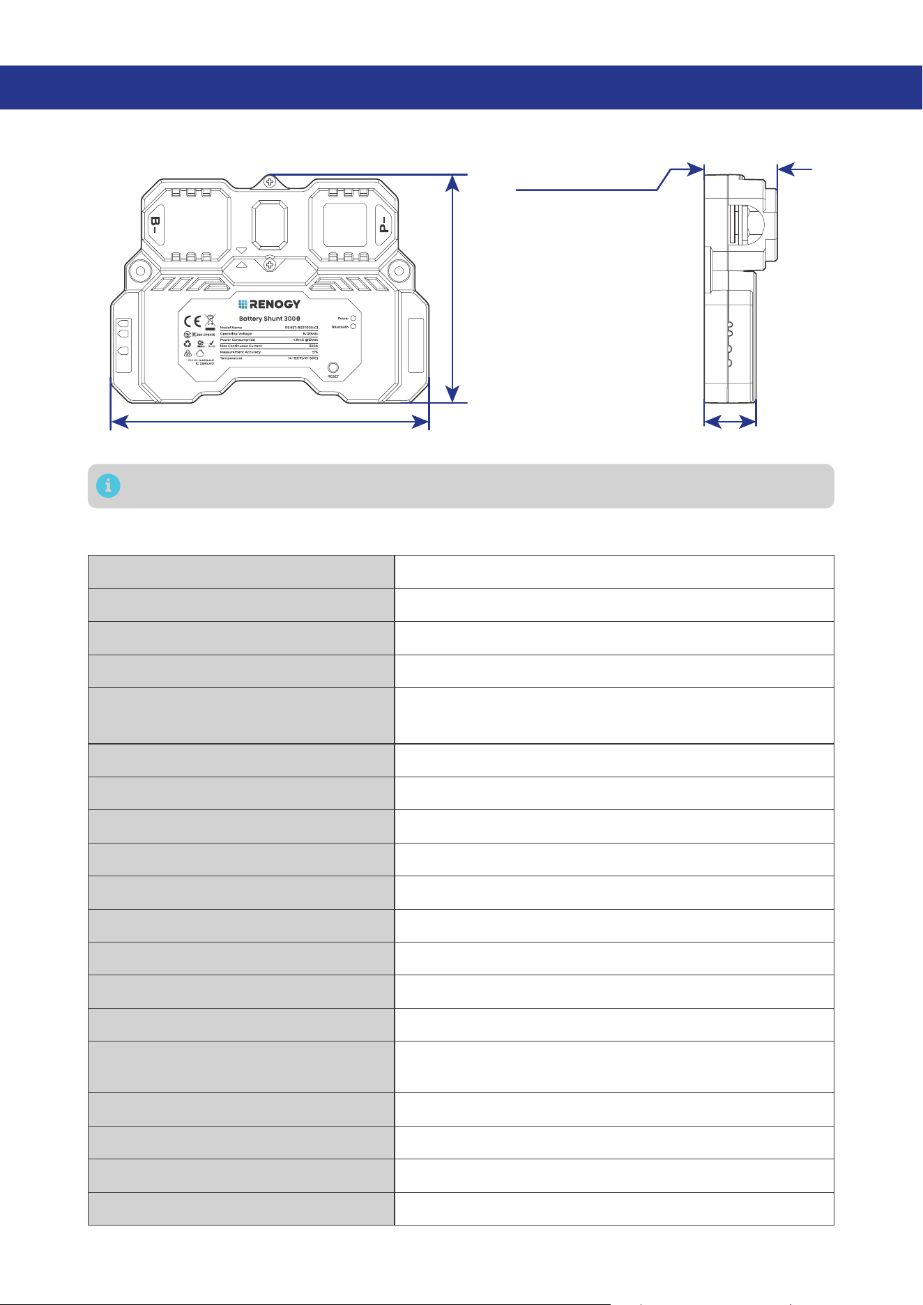
9. Dimensions and Specifications
9.1. Dimensions
5.27 in (134 mm)
3.82 in
(97 mm)
1.22 in (31 mm)
0.87 in (22 mm)
B1
B2
T1
Dimension tolerance: ±0.5 mm (0.2 in)
9.2. Technical Specifications
Product Name Renogy Battery Shunt 300
Model Name RSHST-B02P300-G1
Operating Voltage 8V to 120V DC
Power Consumption < 0.1 W
Communication
z
Bluetooth LE
z
Bluetooth Mesh
Max Continuous Current 300A
Max Peak Current 500A (< 10s)
Current Accuracy ±1%
Current Resolution 0.01A
Battery Capacity (Ah) 1 to 6500Ah
Voltage Input Range 8V to 120V DC
Voltage Input Resolution 10 mV
Battery Connector M10 bolts
Temperature Sensor Range -4°F to 176°F (-20°C to 80°C)
Temperature Sensor Accuracy ±1%
Operating Temperature 14°F to 122°F (-10°C to 50°C)
Operating Humidity 0% to 95% RH
Operating Altitude Less than 6,562 ft (2000m)
Installation Surface mounting

— 28 —
Dimensions 5.27 x 3.82 x 1.22 in (134 x 97 x 31 mm)
Weight 0.57 lb (260g)
Certifications CE, FCCID, IC ID, RCM, TSCA,RoHS, UN38.3, and TELEC
Warranty 1 year
— 29 —
10. Maintenance
10.1. Inspection
For optimum performance, it is recommended to perform these tasks regularly.
z
Check the appearance of the Renogy Battery Shunt 300 to make sure it is clean and dry.
z
Ensure the Renogy Battery Shunt 300 is installed in a clean, dry and ventilated area.
z
Ensure there is no damage or wear on the cables.
z
Ensure the firmness of the connectors and check if there are any loose, damaged or burnt
connections.
z
Ensure that the Battery indicator and Fault indicator are in normal state.
z
Ensure there is no any corrosion, insulation damage, or discoloration marks of overheating or
burning.
Risk of electric shock! Make sure that all power is turned off before touching the terminals on the
Renogy Battery Shunt 300.
In some applications, corrosion may exist around the contacts inside the connector. Corrosion
can loosen springs and increase resistance, leading to premature connection failure. Please
apply dielectric grease to each connector contact periodically. Dielectric grease repels moisture
and protects the connector contacts from corrosion.
10.2. Cleaning
Follow the steps below to clean the Renogy Battery Shunt 300 regularly.
z
Shut down Renogy Battery Shunt 300. If you clean the inside of the device, you need to disconnect
the power supply.
z
Wipe the charger housing and connector contacts with a damp cloth or non-metallic brush. If it is
not clean after wiping, use a household cleaner.
z
Dry the Renogy Battery Shunt 300 with a clean cloth and keep the area around the Renogy Battery
Shunt 300 clean and dry.
z
Make sure the Renogy Battery Shunt 300 is completely dry before reconnecting the connector to the
Renogy Battery Shunt 300.
10.3. Storage
Follow the tips below to ensure that the Renogy Battery Shunt 300 is stored well.
z
Disconnect all connectors that are connected to the Renogy Battery Shunt 300.
z
By applying dielectric grease to each connector contact, the dielectric grease repels moisture and
protects the connector contacts from corrosion.
11. Emergency Responses
In the event of any threat to health or safety, always begin with the steps below before addressing other
suggestions.
z
Immediately contact the fire department or other relevant emergency response team.
z
Notify all people who might be affected and ensure that they can evacuate the area.
Only perform the suggested actions below if it is safe to do so.
11.1. Fire
1. Disconnect all cables connected to the Renogy Battery Shunt 300.
2. Put out the fire with a fire extinguisher. Acceptable fire extinguishers include water, CO2, and ABC.
Do not use type D (flammable metal) fire extinguishers.
11.2. Flooding
1. If the Renogy Battery Shunt 300 is submerged in water, stay away from the water.
2. Disconnect all cables connected to the Renogy Battery Shunt 300.
11.3. Smell
1. Disconnect all cables connected to the Renogy Battery Shunt 300.
2. Make sure nothing is in contact with the Renogy Battery Shunt 300.
3. Ventilate the room.
11.4. Noise
1. Disconnect all cables connected to the Renogy Battery Shunt 300.
2. Make sure no foreign objects are stuck in the Renogy Battery Shunt 300 connector.
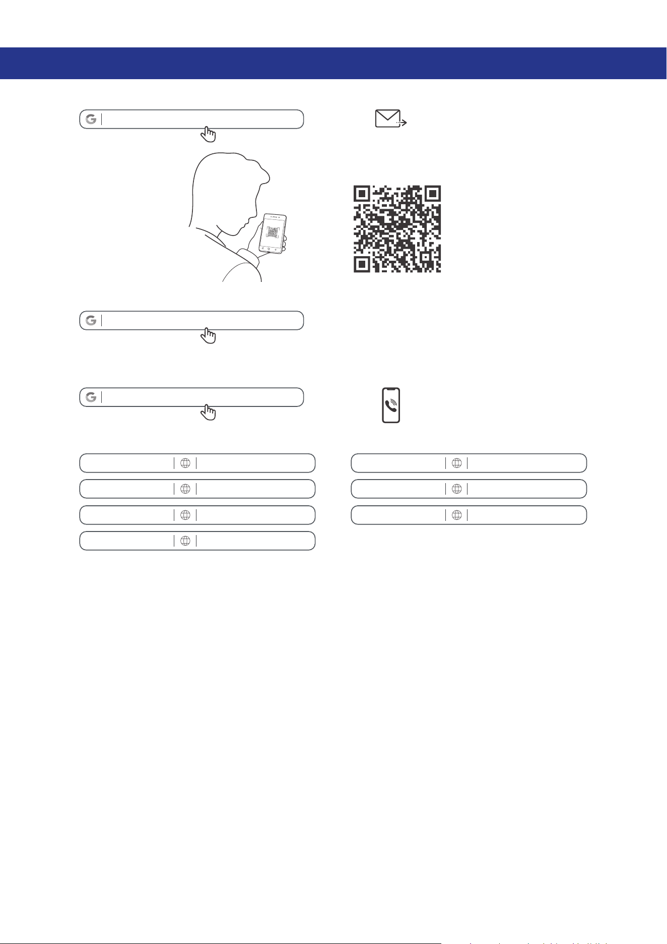
Renogy Support
To discuss inaccuracies or omissions in this quick guide or user manual, visit or contact us at:
renogy.com/support/downloads
contentservice@renogy.com
Questionnaire Investigation
To explore more possibilities of solar systems, visit Renogy Learning Center at:
renogy.com/learning-center
For technical questions about your product in the U.S., contact the Renogy technical support team
through:
renogy.com/contact-us
1(909)2877111
For technical support outside the U.S., visit the local website below:
Canada ca.renogy.com China www.renogy.cn
Australia
au.renogy.com Japan jp.renogy.com
Other Europe eu.renogy.com Germany de.renogy.com
United Kingdom uk.renogy.com

RENOGY.COM
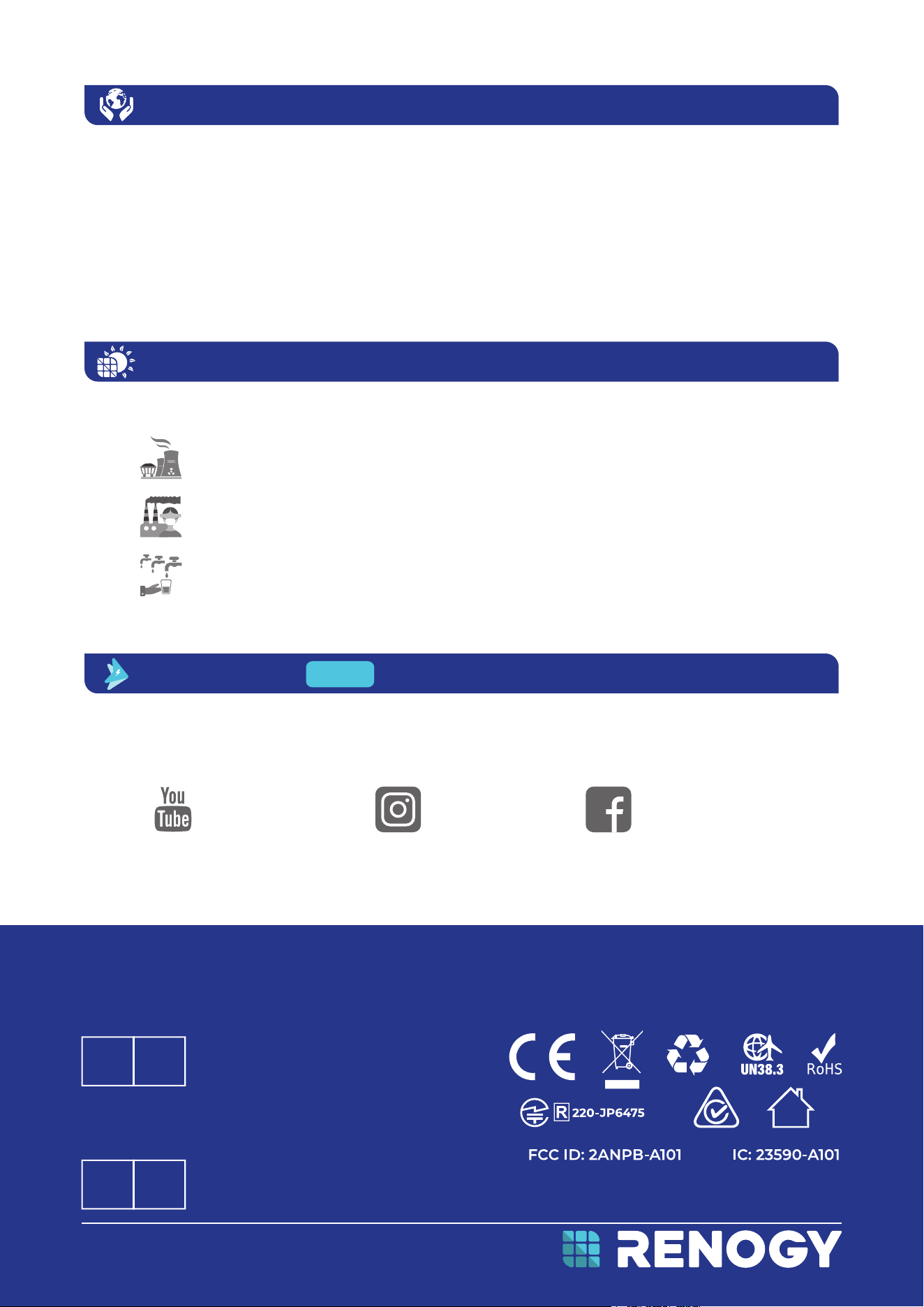
Renogy aims to empower people around the world through education and distribution of DIY-friendly
renewable energy solutions.
Renogy Power Plus allows you to stay in the loop with upcoming solar energy innovations, share your
experiences with your solar energy journey, and connect with like-minded people who are changing
the world in the Renogy Power Plus community.
We intend to be a driving force for sustainable living and energy independence.
In support of this eort, our range of solar products makes it possible for you to minimize your carbon
footprint by reducing the need for grid power.
Renogy Empowered
Live Sustainably with Renogy
Did you know? In a given month, a 1kW solar energy system will...
Save 170 pounds of coal from being burned
Save 300 pounds of CO2 from being released into the atmosphere
Save 105 gallons of water from being consumed
@Renogy Solar @Renogy@renogyocial
Renogy Power
PLUS
Renogy reserves the right to change the contents of this manual without notice.
eVatmaster Consulting GmbH
Rodgau,Hessen,Germany
Raiffeisen Street2 B11, 63110
EC REP
Manufacturer: RENOGY New Energy Co.,Ltd
Address: No.66, East Ningbo Road Room 624-625 Taicang German
Overseas Students Pioneer Park JiangSu 215000 CN
EVATOST CONSULTING LTD
London, United Kingdom, EC2R 8AY
Office 101 32 Threadneedle Street,
UK REP
Manufacturer: RENOGY New Energy Co.,Ltd
Address: No.66, East Ningbo Road Room 624-625 Taicang German
Overseas Students Pioneer Park JiangSu 215000 CN
FCC & RSS
FCC Statement
This device complies with Part 15 of the FCC Rules. Operation is subject to the following two conditions:
(1) This device may not cause harmful interference, and
(2) This device must accept any interference received, including interference that may cause undesired
operation.
Warning: Changes or modifications not expressly approved by the party responsible for compliance
could void the user’s authority to operate the equipment.
This equipment has been tested and found to comply with the limits for a Class B digital device,
pursuant to Part 15 of the FCC Rules. These limits are designed to provide reasonable protection against
harmful interference in a residential installation. This equipment generates uses and can radiate radio
frequency energy and, if not installed and used in accordance with the instructions, may cause harmful
interference to radio communications. However, there is no guarantee that interference will not occur in a
particular installation. If this equipment does cause harmful interference to radio or television reception,
which can be determined by turning the equipment off and on, the user is encouraged to try to correct
the interference by one or more of the following measures:
(1) Reorient or relocate the receiving antenna.
(2) Increase the separation between the equipment and receiver.
(3) Connect the equipment into an outlet on a circuit different from that to which the receiver is
connected.
(4) Consult the dealer or an experienced radio/TV technician for help.
FCC Radiation Exposure Statement
This equipment complies with FCC radiation exposure limits set forth for an uncontrolled environment.
This equipment should be installed and operated with minimum distance 20cm between the radiator &
your body.
RSS Standard
This device complies with Industry Canada license exempt RSS standard(s). Operation is subject to the
following two conditions:
(1) This device may not cause interference, and
(2) This device must accept any interference, including interference that may cause undesired
operation of the device.
The device is compliance with RF exposure guidelines, users can obtain Canadian information on RF
exposure and compliance. The minimum distance from body to use the device is 20cm.
RENOGY.COM
Renogy aims to empower people around the world through education and distribution of DIY-friendly
renewable energy solutions.
Renogy Power Plus allows you to stay in the loop with upcoming solar energy innovations, share your
experiences with your solar energy journey, and connect with like-minded people who are changing
the world in the Renogy Power Plus community.
We intend to be a driving force for sustainable living and energy independence.
In support of this eort, our range of solar products makes it possible for you to minimize your carbon
footprint by reducing the need for grid power.
Renogy Empowered
Live Sustainably with Renogy
Did you know? In a given month, a 1kW solar energy system will...
Save 170 pounds of coal from being burned
Save 300 pounds of CO2 from being released into the atmosphere
Save 105 gallons of water from being consumed
@Renogy Solar @Renogy@renogyocial
Renogy Power
PLUS
Renogy reserves the right to change the contents of this manual without notice.
eVatmaster Consulting GmbH
Rodgau,Hessen,Germany
Raiffeisen Street2 B11, 63110
EC REP
Manufacturer: RENOGY New Energy Co.,Ltd
Address: No.66, East Ningbo Road Room 624-625 Taicang German
Overseas Students Pioneer Park JiangSu 215000 CN
EVATOST CONSULTING LTD
London, United Kingdom, EC2R 8AY
Office 101 32 Threadneedle Street,
UK REP
Manufacturer: RENOGY New Energy Co.,Ltd
Address: No.66, East Ningbo Road Room 624-625 Taicang German
Overseas Students Pioneer Park JiangSu 215000 CN