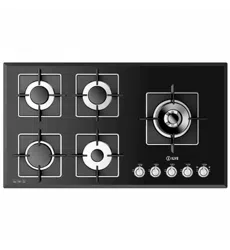
EN User’s manual
GAS
COOKTOPS
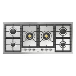
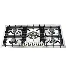
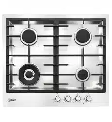
- UHC P (75/95/125/36/48/965/1265)
- UHC PT (75/95/125/36/48/965/1265)
- UHC PM (95/125)
- UHC PMT (95/125)

2

3
- NEVER use this appliance as a space heater to heat or
warm the room. Doing so may result in carbon monoxide
poisoning (only for GAS cooking).
- Keep appliance area clear and free from combustible
materials, gasoline and other ammable vapors and liquids.
- Before beginning, please read these instructions
completely and carefully.
- Do not remove permanently axed labels, warnings, or
plates from the product. This may void the warranty.
- Please observe all local and national codes and ordinances.
- Please ensure that this product is properly grounded.
- The installer should leave these instructions with the
consumer who should retain for local inspector’s use and
for future reference.
- Installation must conform with local codes or in absence of
codes, the National Fuel Gas Code ANSIZ223.1/NFPA 54
latest edition. Electrical installation must be in accordance
with the National Electrical Code, ANSI/NFPA70 latest
edition and/or local codes. IN CANADA:
- Installation must be in accordance with the current CAN/
CGA-B149.1 National Gas.
- Installation Code or CAN/CGA-B 149.2, Propane.
Installation Code and/or local codes. Electrical installation
must be in accordance with the current CSA C22.1
Canadian Electrical Codes Part 1 and/or local codes.
- Installation of any gas –red equipment should be made by
a licensed plumber. A manual gas shut-o valve must be
installed in the gas supply line ahead of the oven in the gas
stream for safety and ease of service.
- In Massachusetts: All gas products must be installed by
a “Massachusetts” licensed plumber or gastter. A “T”
handle type manual gas valve must be installed in the gas
supply line to this appliance.
- The manufacturer will not be responsible for any damage
to property or to persons caused by incorrect installation
or improper use of the appliance.
- The manufactured reserves the right to make changes to its
products when considered necessary and useful, without
aecting the essential safety and operating characteristics.
- This appliance has been designed for non-professional,
domestic use only.
- This appliance must be used only for the purposes for
which it was intended. Any other use is incorrect and
therefore dangerous.
- Possible hazards may result from using this appliance for
storage space.
- Appliances are not intended for manufactured (mobile)
home installation.
- WARNING: If the information in this manual is not
followed exactly, a ne or explosion may result causing
property damage, personal injury or death.
- Do not store or use gasoline or other ammable vapors and
liquids in the vicinity of this or any other appliance.
- WHAT TO DO IF YOU SMELL GAS:
- Do not try to light any appliance.
- Do not touch any electrical switch.
- Do not use any phone in your building.
- Immediately call your gas supplier from a neighbor’s
phone. Follow the gassupplier’s instructions.
- If you cannot reach your gas supplier,call the re
department.
- Installation and service must be performed by a qualied
installer, service agency or the gas supplier. Keep appliance
area clear and free from combustible materials, gasoline
and other ammable vapors and liquids.
IMPORTANT - PLEASE READ AND FOLLOW

4
IMPORTANT INSTRUCTION
- Keep appliance area clear and free from combustible
materials, gasoline and other ammable vapors and liquids.
All Appliances:
- CAUTION: Do Not Leave Children Alone - Children should
not be le alone or unattended in area where appliance is
in use.
- They should never be allowed to sit or stand on any part
of the appliance. Do not store items of interest to children
above or at the back of this appliance, as they could climb
on the appliance to reach items and be injured.
- Wear Proper Apparel - Loose-tting or hanging garmets
should never be worn while using the appliance.
- User Servicing - Do not repair or replace any part of the
appliance unless specically recommended in the manual.
- All other servicing should be referred to a qualied
technician.
- Storage in or on Appliance - Flammable materials should
not be stored near surface units.
- Do Not Use Water on Grease Fires - Smother re or ame
or use dry chemical or foam type extinguisher.
- Use Only Dry Potholders - Moist or damp potholders on
hot surfaces may result in burns from steam. Do not let
potholder touch hot heating elements. Do not use a towel
or other bulky cloth.
- When using this appliance, do not touch grates, burner
caps, burner bases or any other parts in proximity to the
ame. These components may be hot enough to cause
burns.
- Never leave this appliance unattended when in use.
Boilovers and greasy spills may smoke or ignite
- Do not heat unopened food containers, such as baby food
jars and cans. Pressure build-up may cause the container
to burst and cause injury.
- Before performing service, shut o gas supply by closing
the gas shut-o valve and shut o elec-tricity to this
appliance
- For safety when cooking, set burner controls so ame does
not extend beyond the bottom of pan.
- Wear proper apparel. Loose-tting or hanging garments
should never be worn while using this appliance.
- Use extreme caution when moving a grease kettle or
disposing of hot grease.
- Clean only those parts listed in this guide.
- Do not repair or replace any part of this appli-ance unless
specically recommended in literature accompanying this
appliance.
- Do not obstruct the ow of air to ensure proper combustion
and ventilation.
- IMPORTANT: Do not install a ventilation system that blows
air downward toward this gas cooking appliance. This type
of ventilation system may cause ignition and combustion
problems with this gas cooking appliance resulting in
personal injury or unintended operation.
- Proper Installation – Be sure your appliance is properly
installed and grounded by a qualied technician.
- Never Use Your Appliance for Warming or Heating the
Room.

5
INSTALLATION INSTRUCTIONS
This appliance shall only be installed by an authorized person.
This appliance shall be installed in accordance with the
manufactures installation instructions, IMPORTANT: this
appliance must be installed in accordance with the norms in
force of the country concerned.
The installation of this appliance must conform to local codes
and ordinances. In the absence of local codes. Installations
must conforms to American National Standards, National Fuel
Gas Code ANSI Z223.1-54-NFPA54
If local codes permit, a flexible metal appliance connection with
the new AGA or CGA certified design, max. 5 feet (1,5m) long,
½” I.D. recommended for connecting this cooktop to the gas
supply line. Do not bend or damage the flexible connector when
moving the cooktop. The pressure regulator has ½” female
pipe thread. You will need to determine the fitting required,
depending on the size of your gas supply line, the flexible metal
connector and the shutoff valve.
The appliance , when installed, must be electrically grounded
in accordance with local codes or, in absence of local codes,
with the National Electrical Code, ANSI/NFPA 70, CSA C22.1-
02
The correct voltage, frequency and amperage must be supplied
to the appliance from a dedicated, grounded circuit which is
protected by a properly sized circuit breaker or time delay fuse.
The proper voltage, frequency and amperage ratings are listed
on the product rating plate.
The appliance and its individual shut off valve must be
disconnected from the gas supply piping system any pressure
testing of that system at test pressure in excess of ½psi (3,5kPa).
The appliance must be isolated from the gas supply piping
system by closing its individual manual shutoff valve during
any pressure testing of the gas supply piping system at test
pressure equal to or less than ½psi (3,5kPa).
For use with a pressure regulator. The regulator supplied must
be used with this appliance; it shall be properly installed in
order to be accessible when appliance is installed in definitive
position.
The gas appliance pressure regulator must be set for the gas
with which the appliance is used.
This appliance can be used with Natural gas and LP Gas.
It is shipped from the factory adjusted for use with Natural
gas: CONVERSION FIXED ORIFICES ARE LOCATED IN THE
LITERATURE PACK SUPPLIED WITH THE UNIT.
Injectors kit for the change of type of gas are contained inside
the package jointly with the hob installation kit and Instruction
booklet. The maximum inlet gas supply pressure incoming
to the gas appliance pressure regulator is 20” water column
(5kPa). The minimum gas supply pressure for checking the
regulator setting shall be at least 1”w.c.(249Pa) above the inlet
specified manifold pressure to the appliance (this operating
pressure is 5”w.c. for Natural Gas and 10”w.c. for LP Gas). All
opening and holes in the wall and floor, back and under the
appliance shall be sealed before installation of the appliance.
ATTENTION: A manual valve shall be installed in an accessible
location in the gas line external to the appliance for the purpose
of turning on or shutting off gas to the appliance.
WARNING: Do not use aerosol sprays in the vicinity of this
appliance while it is in operation.
The appliances should not be installed with a ventilation system
that blows air downward toward the range.
A ventilation hood is recommended(but not required) for use
with the gas cooktop.
Warning! Before removing the appliance disconnect the
electric power supply cable and close the relevant shut off
valve. Make sure that the electric power supply cable is not
damaged during cleaning / mainteinance operation.
6
GAS CONNECTION
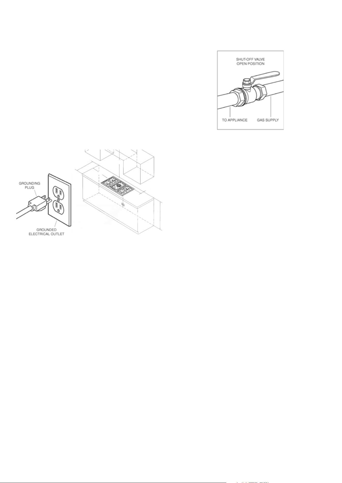
The gas cooktop requires a 120 VAC, 60Hz electrica lsupply to
operate the electronic ignition system. The service should have
its own 15 amp circuit breaker. A ground fault circuit interrupter
(GFCI)is not recommended and may cause interruption of
operation. The cooktop is equipped with a powercord witha 3
prong grounding plug. To minimize shock hazard, the power
cord must be plugged into a mating 3 prong grounded outlet,
grounded to conform with the National Electrical Code, ANSI/
NFPA 70 latest edition ,or Canadian Electrical Code (CSA) and
all local codes and ordinances. Refer to the illustration below.
IMPORTANTNOTE:Do not ground to a gas pipe.
Grounded wall Outlet
WARNING
Electrical Grounding Instructions
This appliance is equipped with a (three-prong) grounding
plug for your protection against shock hazard and should be
plugged directly into a properly grounded receptacle. Do not
cut or remove the grounding prong from this plug.
ll gas connections must be made according to national and
local codes. This gas supply (service) line must be the same
size or grater than the inlet line of the appliance. This range
uses a ½” NPT inlet. Sealant on all pipe joints must be resistive
to LP gas.
1. Manual Shut-o Valve: This installer-supplied valve must be
installed in the gas service line ahead of the appliance in
the gas stream and in a position where it can be reached
quickly in the event of an emergency. The manual shut-o
valve shall be installed properly in order to be accessible
when appliance is installed in denitive position. In
Massachusetts: A ‘T’ handle type manual gas valve must
be installed in the gas supply line to this appliance. Refer
to the illustration.
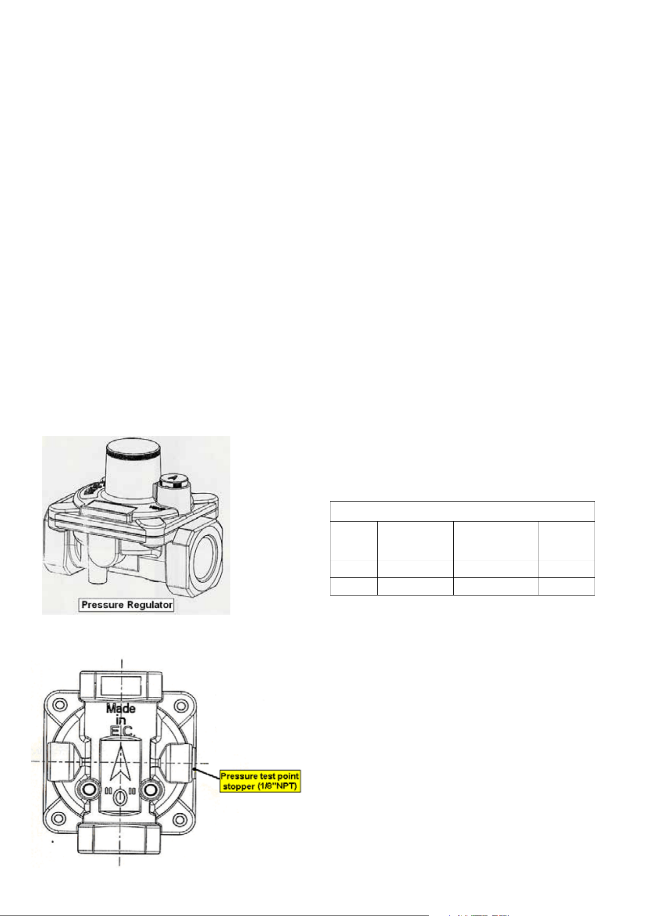
2. Pressure Regulator
- All heavy duty, commercial type cooking equipment must
have a pressure regulator on the incoming service line
for safe and ecient operation, since service pressure
may uctuate with local demand. The pressure regulator
is supplied separately with the appliance; regulator has
two female threads ½” NPT; it shall be installed properly
in order to be accessible when appliance is installed in
denitive position.
- This range can be used with Natural or LP/Propane gas.
It is shipped from the factory adjusted for use with natural
gas. The orice hoods must be screwed snug when LP/
Propane gas is used(see LP/Propane conversion).
- The appliance, its individual shut-o valve, and pressure
regulator must be disconnected from the gas supply
piping system during any pressure testing of that system at
pressure is in excess of 1/2psig(3.45kPa).
- The appliance must be isolated from the gas supply piping
system by closing its individual manual shut-o valve
during any pressure testing of gas supply piping system at
test pressures equal to or less than 1/2psig (3.45kPa).
3. Flexible Connections:
- If the unit is to be installed with exible couplings and/or
quick disconnect ttings, the installer must use an heavy
duty, AGA design-certied commercial exible connector
of at least ½”(1.3cm)ID NPT(with suitable strain relieves) in
compliance with ANSI Z21.41 and Z21.69 standards.
- In Massachusetts: The unit must be installed with a 36” (3-
foot) long exible gas connector.
- In Canada: CAN 1-6.10-88 metal connectors for gas
appliances and CAN 1-6.9M79 quick disconnect device
for use with gas fuel.
CAUTION: Leak testing of the appliance shall be conducted
according to the manufacturer’s instructions. Before placing
the gas cooktop into operation, always check for leaks with
a soapy water solution of other acceptable method. DO NOT
USE AN OPEN FLAME TO CHECK FOR LEAKS!

7
PERFORMANCE CHECKLIST
All burners are tested before leaving the factory. There are no
adjustments for the burners if connected according to the
information on the rating plate. Check each burner for proper
operations. Flames should be blue in all settings. If service is
required, contact your dealer for the name of their authorized
service agency. Gas conversions and initial installation are not
responsibility of the manufacturer.
The installer should carry out the following performance
checks. Refer to instructions below.
1. Check surface burner ignition.
2. Check air shutter adjustment sharp blue flame, no yellow
tipping, shooting or flame lifting.
3. Check low flame adjustment
4. Check for gas leaks (odors) at all gas connections.
REQUIREMENTS
Room ventilation – Location and venting.
ATTENTION: A exhaust fan may be used with the appliance; in
each case it shall be installed in conformity with the national
standards in force.
ATTENTION: Exhaust hood operation may affect other vented
appliances; in each case it shall be installed in conformity with
the national standards in force.
CONVERSION TO DIFFERENT TYPES OF GAS
Any conversion required must be performed by your dealer or
a qualified licensed plumber or gas service company. Please
provide the service person with this manual before work is
started on the range.(Gas conversions are the responsibility of
the dealer or end user.)
WARNING
This conversion kit shall be installed by a qualified service
agency in accordance with the manufacturer’s instructions and
all applicable codes and requirements of the authorityhaving
jurisdiction. If the information in these instructions is not
followed exactly, a fire, explosion or production of carbon
monoxide may result causing property damage, personal injury
or loss of life. The qualified service agency is responsible for
the proper installation of this kit. The installation is not proper
and complete until the operation of the converted appliance
is checked as specified in the manufacturer’s instructions
supplied with the kit.
CAUTION
Before proceeding with the conversion, shut off the gas supply
to the appliance prior to disconnecting the electrical power.
The appliance is supplied for use with a certain type of gas; if
this has to be varied, you must change the burner injectors,
adjust the air flow rate and the minimum gas flow.
Before carrying out these operations you must disconnect the
electric power supply of the gas cooktop to avoid accidental
contacts.
Before carrying out any maintenance work, disconnect the
appliance from the gas and electric supply.
8
ADAPTATION OF THE PRESSURE REGULATOR FOR USE WITH
DIFFERENT TYPE OF GAS
The pressure regulator supplied with the appliance is a
convertible type pressure regulator for use with Natural Gas at
a nominal outlet pressure of 5”w.c. or LP gas at a nominal outlet
pressure of 10”w.c. and it is pre-arranged from the factory to
operate with one of these gas/pressure as indicated in the
pre-arranging labels affixed on the appliance, package and
Instruction booklet.
If Natural gas is converted to LP gas, also by-pass orice has
to be change.
The regulating crew of by-pass orice must be fully screwed in.
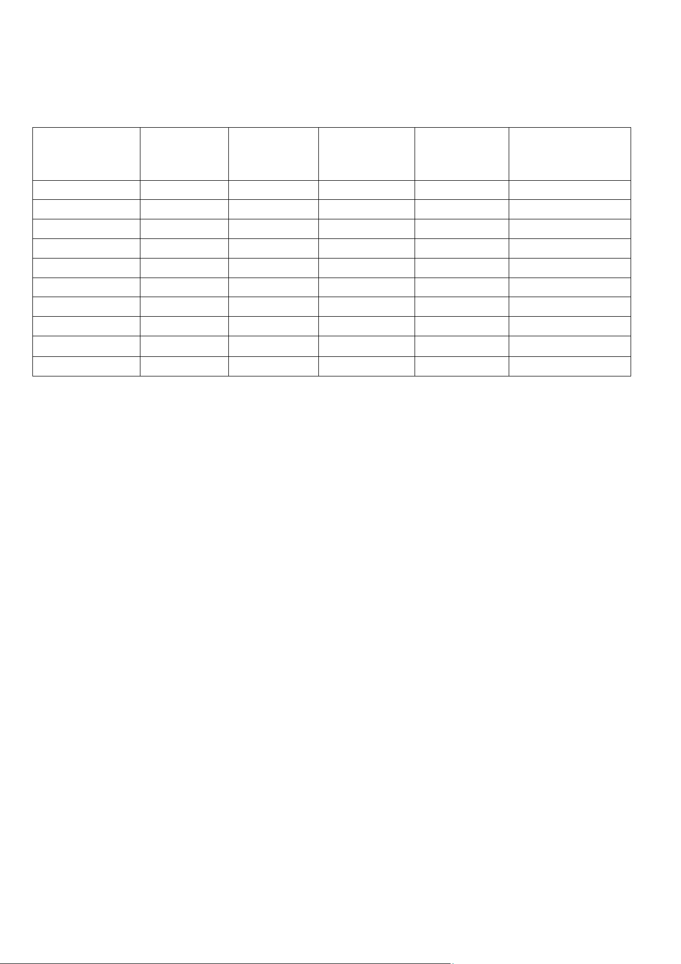
To convert the regulator (Fig.1 and Fig.2) for use with the other
gas dierent from which one it is pre-arranged it is enough
perform the following operations:
- Unscrew by hand the upper metal stopper of the regulator.
- Unscrew by hand the white plastic piece screwed under the
above mentioned metal stopper, aerward screw it again
in opposite way under the metal stopper(for gas reference
see the written “LP” and “NAT” with relative indicating
arrows on the white piece).
- Screw again by hand the metal stopper in the original
position on the regulator. Operating in this way the gas
regulator is converted for use with the other gas/pressure
-
Fig. 1 Pressure regulator
Fig. 2 Pressure regulator; pressure test-point stopper is pointed out
See the table below for GAS supply pressure requirements
Note: Cooking with the probe cannot be used in the “DEFROST,”
“QUICK START,” “PIZZA,” and “ECO” functions.
With the oven in stand-by, insert the meat probe into the
appropriate connection socket, which is usually located on
the left wall of the oven. The display will show “MEAt” for 2
seconds, and the probe symbol will start flashing. Then, the
default probe temperature value (75°C) will appear on the
display. Turn and then press the control knob to select the
desired end cooking temperature between the two limits of
40°C and 100°C (internal temperature of the food). After 4
seconds from the last setting, the chosen temperature will be
stored, and the probe symbol will remain lit. Turn on the oven,
select the cooking function, and set the desired temperature
using the appropriate knobs. The temperature read by the
probe will then appear on the display. When the programmed
probe temperature is reached, the oven will turn off, an audible
signal will sound, “End” will flash on the display, and the oven
will switch to “cooking finished” mode.
During cooking, it is always possible to modify the probe
temperature by pressing the knob 3 times and then turning the
control knob.
Note: If the probe is inserted into the connection socket during
cooking, the oven will turn off, and “Off” will appear on the
display.
If the probe is removed from the socket during cooking, the
oven will turn off, and “Off” will appear on the display.
Gas Supply Specications
Gaz Type
Pression
d’admission
(WC)
Min. Gas Supply
Pressure (WC)
Max. Input
Pressure
Natural 5 6 1/2 psi
PL 10 11 1/2 psi
liance must be disconnected from the GAS supply pièping
system during any pressure testing of that system.
9
CHANGING THE INJECTORS AND ADJUSTING THE AIR
TABLE 2
Burner Gas Input rate
[Btu/h]
Orifice size
(1/100) mm
Simmer rate
[Btu/h]
By-pass orifice size
(1/100) mm
(* only for UHCP36..,
UHCP48..)
SR NATURAL (A) 7000 120 1400 Adj
R NATURAL (A) 10500 145 2000 Adj
DUAL NATURAL (A) 18000 75+190 6300 Adj
DUAL NATURAL (A) 22000 75+210 6300 Adj
DUAL (only AUX) NATURAL (A) 2800 75 900 Adj
SR LP (E) 7000 78 1400 30 / 32*
R LP (E) 10500 95 2000 38 / 40*
DUAL LP (E) 18000 52+120 6800 24+65 / 27*+60*
DUAL LP (E) 22000 52+125 7300 24+65 / 27*+60*
DUAL (only AUX) NATURAL (A) 2800 52 900 24 / 27*
The kit for the gas conversion of the burners is relevant to the
model of the appliance indicated on the label sti-king to the
first page of this booklet.
The kit contains the number and type of orifices necessary for
the conversion and a label to stick onto the old one to show the
new setting ( see table 2)
The appliance is pre-adjusted in factory for the gas indicated
on the label put on the gas inlet pipe. For the conversion to
another gas refer to table 3.
The positions, types of burner and relevant orifices for the
models included in this booklet are depicted in table 3.
The only operation to perform after conversion to a gas different
from that shown on the rating platellabel is the adjustment of
the minimum gas flow. After conversion remember to put the
new gas indication label ( supplied in the conversion kit) as
close as possible to the existing rating plate, then check the
regular ignition of the burners.
If the appliance is installed at an altitude exceeding 2,000 ft,
a new set of orifices can be requested from the supplier or an
authorised service parts distributor.
NOTE: Due to the lower atmospheric pressure at higher
altitudes, foods tend to take longer to cook. Therefore, recipe
adjustments should be made in some cases. In general, no
recipe adjustment is necessary for yeast-risen baked goods,
although allowing the dough or batter to rise twice before
the final pan rising develops a better flavor. Try making the
adjustments below for successful recipes. Take note of the
changes that work best and mark your recipesaccordingly.
You may also consult a cookbook on highalttude cooking for
specific recommendations.
10
CONVERSION KIT INSTALLATION INSTRUCTIONS
C
C
O
O
D
D
E
E
NATURAL GAS
P
P
R
R
O
O
P
P
A
A
N
N
E
E
G
G
A
A
S
S
U
U
H
H
C
C
(
(
P
P
/
/
P
P
T
T
)
)
7
7
5
5
U
U
H
H
C
C
(
(
P
P
/
/
P
P
T
T
)
)
7
7
5
5
N
N
U
U
H
H
C
C
(
(
P
P
/
/
P
P
T
T
)
)
9
9
5
5
-
-
U
U
H
H
C
C
(
(
P
P
/
/
P
P
T
T
)
)
9
9
5
5
(
(
F
F
/
/
F
F
F
F
)
)
U
U
H
H
C
C
(
(
P
P
/
/
P
P
T
T
)
)
9
9
5
5
N
N
-
-
U
U
H
H
C
C
(
(
P
P
/
/
P
P
T
T
)
)
9
9
5
5
(
(
F
F
/
/
F
F
F
F
)
)
N
N
U
U
H
H
C
C
(
(
P
P
M
M
/
/
P
P
M
M
T
T
)
)
9
9
5
5
-
-
U
U
H
H
C
C
(
(
P
P
M
M
/
/
P
P
M
M
T
T
)
)
9
9
5
5
(
(
F
F
/
/
F
F
F
F
)
)
U
U
H
H
C
C
(
(
P
P
/
/
P
P
T
T
)
)
1
1
2
2
5
5
-
-
U
U
H
H
C
C
(
(
P
P
/
/
P
P
T
T
)
)
1
1
2
2
5
5
(
(
F
F
/
/
F
F
F
F
)
)
U
U
H
H
C
C
(
(
P
P
/
/
P
P
T
T
)
)
1
1
2
2
5
5
N
N
-
-
U
U
H
H
C
C
(
(
P
P
/
/
P
P
T
T
)
)
1
1
2
2
5
5
(
(
F
F
/
/
F
F
F
F
)
)
N
N
U
U
H
H
C
C
(
(
P
P
M
M
/
/
P
P
M
M
T
T
)
)
1
1
2
2
5
5
-
-
U
U
H
H
C
C
(
(
P
P
M
M
/
/
P
P
M
M
T
T
)
)
1
1
2
2
5
5
(
(
F
F
/
/
F
F
F
F
)
)
U
U
H
H
C
C
P
P
9
9
6
6
5
5
(
(
6
6
/
/
F
F
)
)
U
U
H
H
C
C
P
P
9
9
6
6
5
5
(
(
6
6
/
/
F
F
)
)
N
N
U
U
H
H
C
C
P
P
1
1
2
2
6
6
5
5
(
(
8
8
/
/
F
F
)
)
U
U
H
H
C
C
P
P
1
1
2
2
6
6
5
5
(
(
8
8
/
/
F
F
)
)
N
N
U
U
H
H
C
C
P
P
3
3
6
6
(
(
6
6
/
/
F
F
)
)
U
U
H
H
C
C
P
P
3
3
6
6
(
(
6
6
/
/
F
F
)
)
N
N
U
U
H
H
C
C
P
P
4
4
8
8
(
(
8
8
/
/
F
F
)
)
U
U
H
H
C
C
P
P
4
4
8
8
(
(
8
8
/
/
F
F
)
)
N
N
C
C
O
O
N
N
V
V
E
E
R
R
S
S
I
I
O
O
N
N
K
K
I
I
T
T
I
I
N
N
S
S
T
T
A
A
L
L
L
L
A
A
T
T
I
I
O
O
N
N
I
I
N
N
S
S
T
T
R
R
U
U
C
C
T
T
I
I
O
O
N
N
S
S
120 78
145 145 95
78
95
190+75
120+52190+75
120+52
145 145
145
120
210+75
145
120
145
190+75 120
95
78
95
78 120+52
145
145
145
120
145
210+75
95
95
95
78
95
125+52
145
145145
210+75
120210+75
145
145 145
145
145
120
145
190+75 120
95
78
95
78 120+52
120
210+75
95
95
95
78
125+52
125+52
120 210+75
78 125+52
95
9595
125+52 78
125+52
95
95 95
95
78125+52
78 125+52
210+75 120
120 210+75
WARNING: save the orifices removed from the appliance for future use
NOTE: To go back to the original set replace old orifices as shown
WARNING: This conversion kit shall be installed by a qualified service agency in accordance with the manufacturer’s instructions
and all applicable codes and requirements of the authority having jurisdiction. If the information in these instructions is not
followed exactly, a fire, explosion or production of carbon monoxide may result causing property damage, personal injury or loss
of life. The qualified service agency is responsible for the proper installation of this kit. The installation is not proper and complete
until the operation of the converted appliance is checked as specified in the manufacturer’s instructions supplied with the kit.
11
BURNERS OF THE HOB
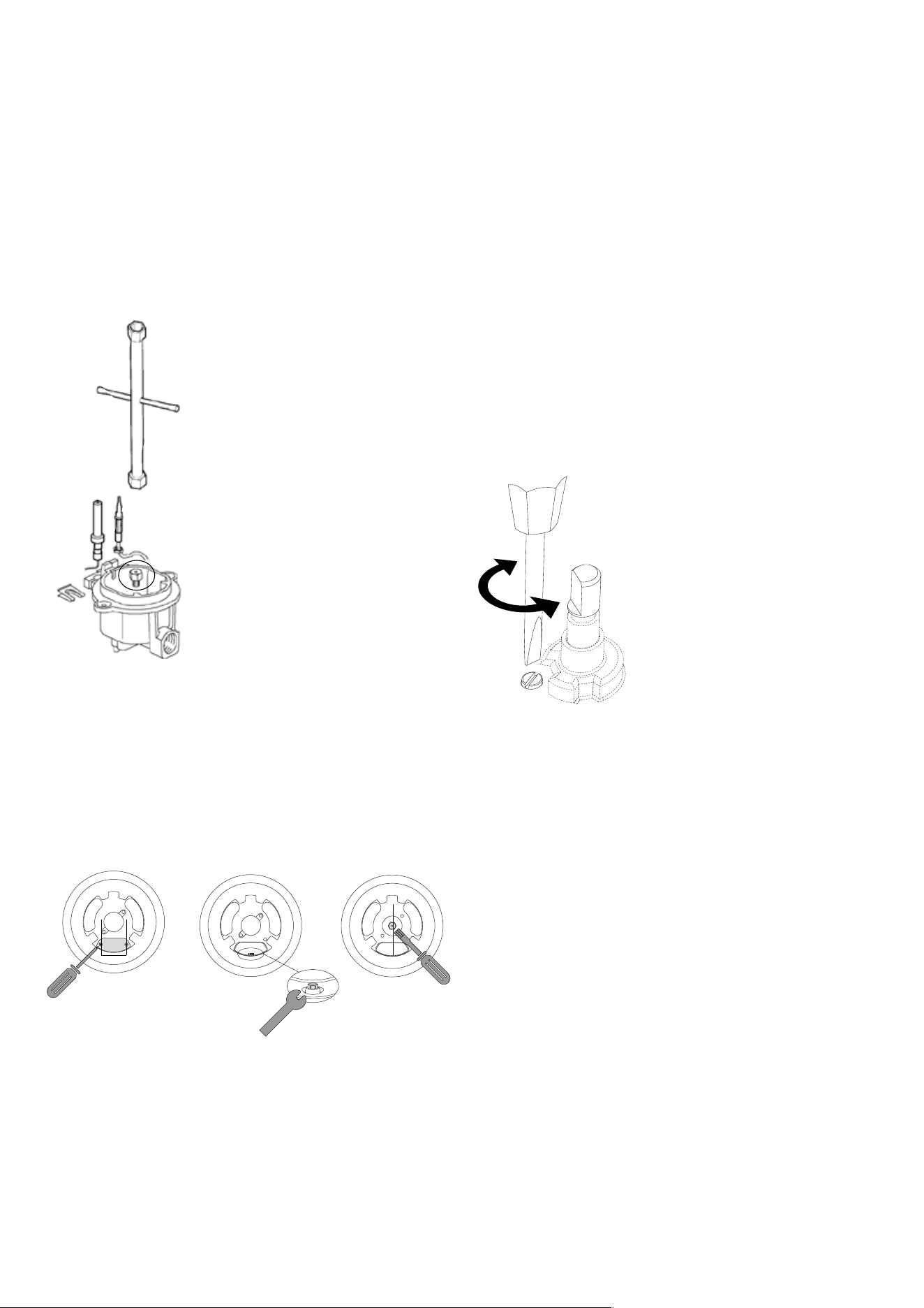
Replacement of the injectors
Procedure: SR - R
1. Remove the grill and the burners from the hob.
2. Burners SR – R:
unscrew injectors “U” using a 7 mm spanner and replace them
with those for the new gas. Save the orifices removed from the
appliance for future use.
U
Procedure: DUAL
1. Dual burners: unscrew the 2 screws “P” and remove cover
“C” fig.2.
2. unscrew injectors “U” using a 7 mm spanner and replace
them with those for the new gas. Save the orifices removed
from the appliance for future use.
Adjusting the minimum gas flow
When installing the gas cooktop you must check that the
minimum gas flow of the burners is correctly regulated. If the
type of gas is changed it is indispensable to adjust the minimum
flow. The regulating procedure is as follows.
A) Burners on the hob.
1. Light one burner at a time and turn the flame up to maximum.
2. Remove the knob of the corresponding gas tap and insert
screwdriver in the screw as showed in figure.
3. Turn the tap to minimum position.
4. Unscrew, turning to the left, to increase the flame, or screw to
the right to decrease it.
5 .If a liquid gas is used (Butane - Propane), the regulating
screw must be fully screwed in.
P
U U
12
INSTRUCTIONS FOR USE
Burners
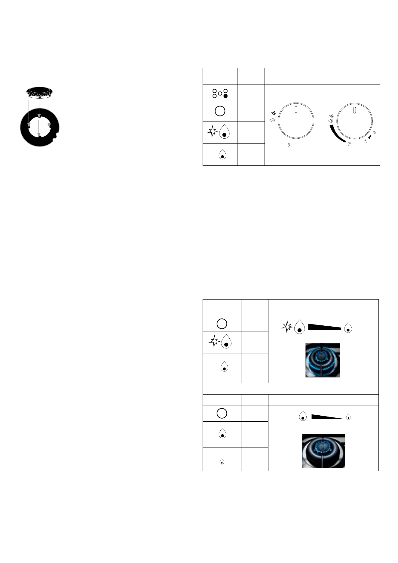
Position the flame divider “b” correctly. To do this, align the
4 teeth “c” of the flame divider with the recess “d” of the
aluminium Cup “a”.
a
b
c
d
Service and maintenance instructions
Replacement Parts.
Authorized replacement parts may be used in performing
service on the appliance. Replacement parts are aval-lable
from factory authorized part distributors.
Service and maintenance only to be carried out by an
authorised person.
To replace parts such burners, valves and electric components,
the hotplate must be removed from the bench top by releasing
the attachment hooks, loosening the attachment screws of
each burner, unscrewing the hotplate altachments nuts which
are visible at the bottom of the surface, removing the hotplate
top and finally replacing the defective parts. Note 1: if the valves
must be replaced, first disassemble the ignitions switches
wires. It is recommended to replace the valve gaskets each
time the valve is replaced.
Note 2: if the main gas pipe needs replacement, make sure it
has the correct welded metal supports for assembly.
WARNING: after first installation of the appliance, after gas
conversion kit installation or after any service intervention
concerning main gas parts of the appliance, make the leak test
using water with soap on the gas connections in order to verify
the correct installation. Do not use fire for gas leak testing.
The test is valid if there is no bubble or foam build-up during a
period of one minute.
Non working appliances
Before calling the After Sales Service, check that the appliance
is connected or that the main switch is activated. After, call
the After Sales Service. The faults must be checked by an
experienced technician.
Lighting the burners
The index above the knobs will help you to find the corresponding
burner. Press the knob by turning it anti- clockwise and bring
it to the ignition position; keep the knob pressed for about 5
seconds so that upon its release the flame remains alight. In
case of unsuccessful ignition wait 5 minutes before relighting
and repeat the operation. By turning the knob, the outer
ring lights up red to indicate the GAS burner in operation
Symbol Function Knob
index
DUAL
DUAL
o
OFF
max
OFF
min
Burners “DUAL”
Identify the knob with the help of the index near the knobs.
Press and turn the knob to the symbol (maximum) for 5
seconds. Once the burner is on, by turning the knob
counterclockwise it gets to its first block that corresponds to
the middle one.
By applying a bit of force, the first block is exceeded and
the outer ring goes out leaving only the little central burner
turned on called AUXILIARY. To adjust the auxiliary burner
on minimum, rotate the knob counterclockwise until it stops.
At this point, to turn the burner back on, rotate the knob
clockwise up to the desired value.
DUAL
Symbol Function Knob
o
OFF
OFF
max
OFF
min
AUX
Symbol Function Knob
o
OFF
OFF
max
OFF
min
13
INSTRUCTIONS FOR USE
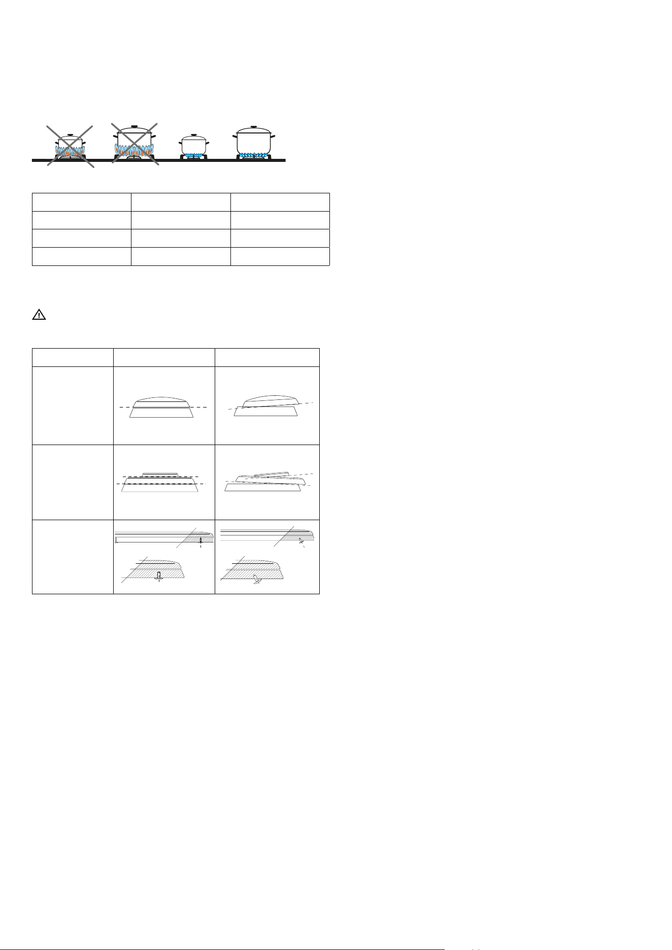
Recommended pans according to burner size:
Burners ID Diameter Ø (cm)
Meduim SR 12 ÷ 20
Large R 20 ÷ 24
Dual - Ring DUAL 12 ÷ 30
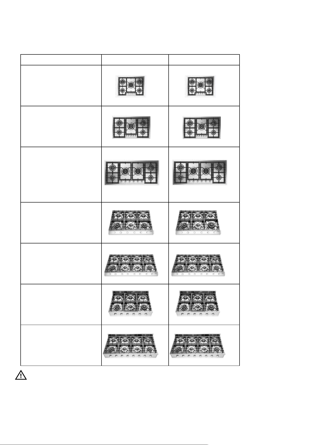
Positioning of the burners
Always check that the burners are properly positioned), with a
uniform ame that is not noisy.
Burners Right Wrong
Medium
Large
Dual Ring
Fish burner
Always check that
the screws below
the burner are
xed
Cleaning and maintenance
ATTENTION: burners with nanotechnological coating
Some cleaning and washing methods are recommended in
order to preserve the
quality of the coating.
Allow the product to cool down at room temperature before
cleaning it. It is recommended not to dip it in cold water when
it is still hot.
Wash with warm water and a minimum of neutral detergent.
Rub with a cloth, better if in natural cellulose, or non-abrasive
sponge.
Do not use dust, iron wool, cloths and abrasive sponges.
Do not let food be charred on the burner. In case stains/colora-
tions may appear on the surface. These traces do not alter the
functionality of the product, and in some cases can be elimina-
ted with this procedure: immerse the product in hot water, with
detergent, wipe gently with a cloth, better if in natural cellulo-
se; in any case, do not use abrasive cloths or sponges. For the
most resistant stains, it is advisable to warm white vinegar
and rub as indicated above.
Avoid leaving the burners in contact with food for a long time,
especially if acidic, such as tomato sauce.
Avoid contact with metal objects; if really needed, use wooden
or plastic objects.
Avoid washing in the dishwasher, a part of the product is not
coated and would get irreparably damaged.
In order for the DUAL burner to function properly, it is important
to keep the ignition channel clean, as shown in the gure below.
14
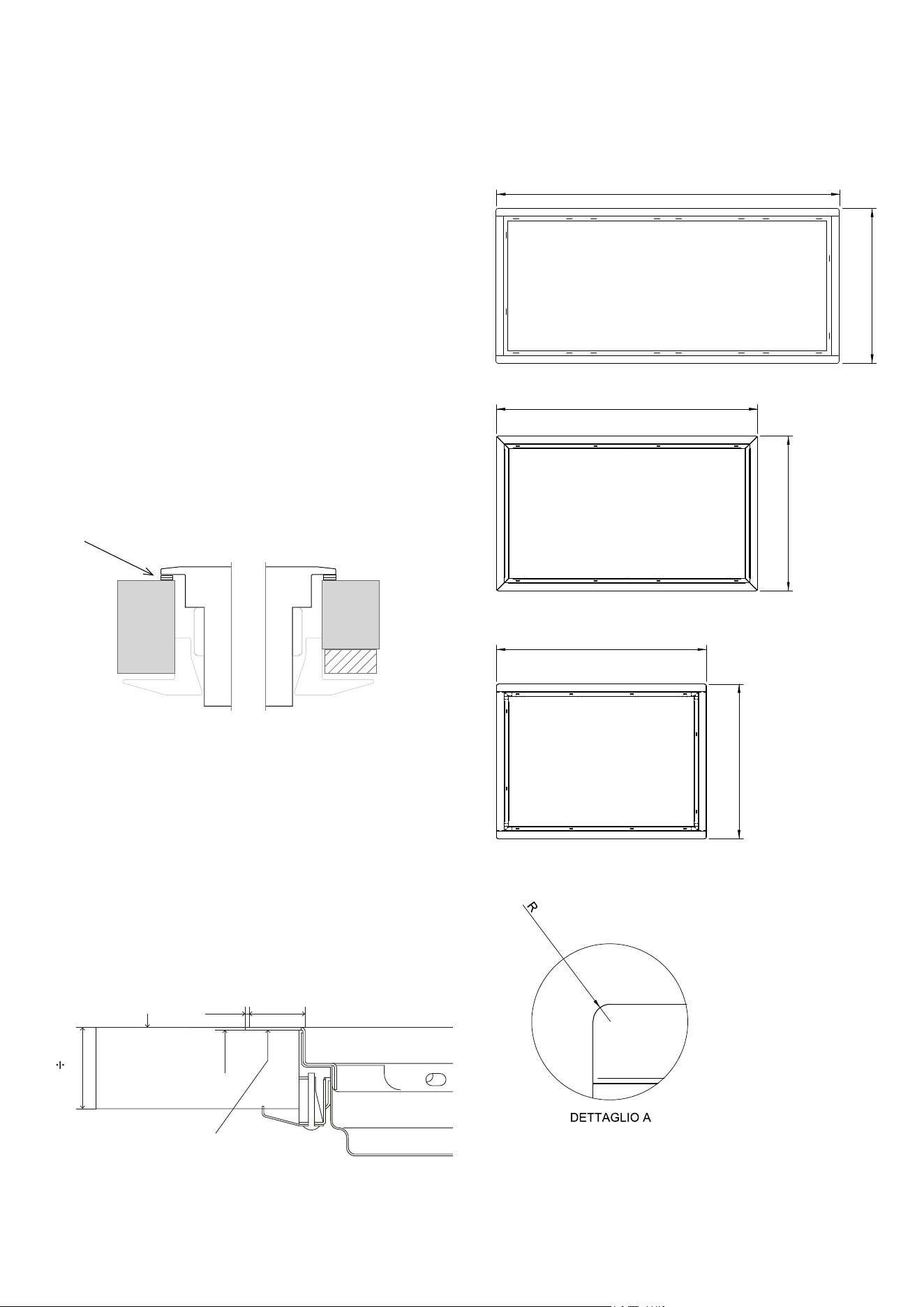
GAS COOKTOP INSTALLATION
Functions
Remove the cooktop, gas pressure regulator, burner grates and
burner caps from the shipping package. Lower the cooktop
into the countertop cut-out opening. Center the cooktop in the
opening and check that the front edge of cooktop is parallel to
the front edge of the countertop. Check that all required cle-
arances are met. Remove the cooktop from the counter-top
opening.
IMPORTANT NOTE: When repositioning the cooktop in the
countertop opening, lift the entire cooktop up from the ope-
ning to prevent scratching the countertop. Apply the foam
strip, included in the hardware package, to the under side of
the cooktop frame. Refer to the illustration below.
Reinsert the cooktop into the countertop opening. Lift the en-
tire cooktop to make adjustments. Attach the brackets to the
bottom of the unit. Insert the clamping screws into the brackets.
Use a screw-driver to tighten the clamping screws against the
underside of the countertop. Refer to the illustration below. Do
not overtighten screws.
IMPORTANT NOTE: Do not seal the cooktop to the countertop.
It must be removed if service is necessary.
GAS PRESSURE REGULATOR Install the gas pressure regula-
tor with the arrow on the regulator pointing up toward the unit
and in a position where you can reach the access cap.
IMPORTANT NOTE: All connections must be wrench-tight-e-
ned. Do not make connections to the regulator too tight, as this
may crack the regulator and causea gasleak. Do not allow the
regulator to turn on the pipe when tightening fittings.
Top
Silicone
0
3/64
0
5/64
1
5/64
1
3/16
1
37/64
UHC (P/PT/PM/PMT) 95
35
3/8
20
7/8
UHC (P/PT) 75
28
3/8
20
7/8
46
7/16
UHC (P/PT/PM/PMT)125
20
7/8
0
15/64
15
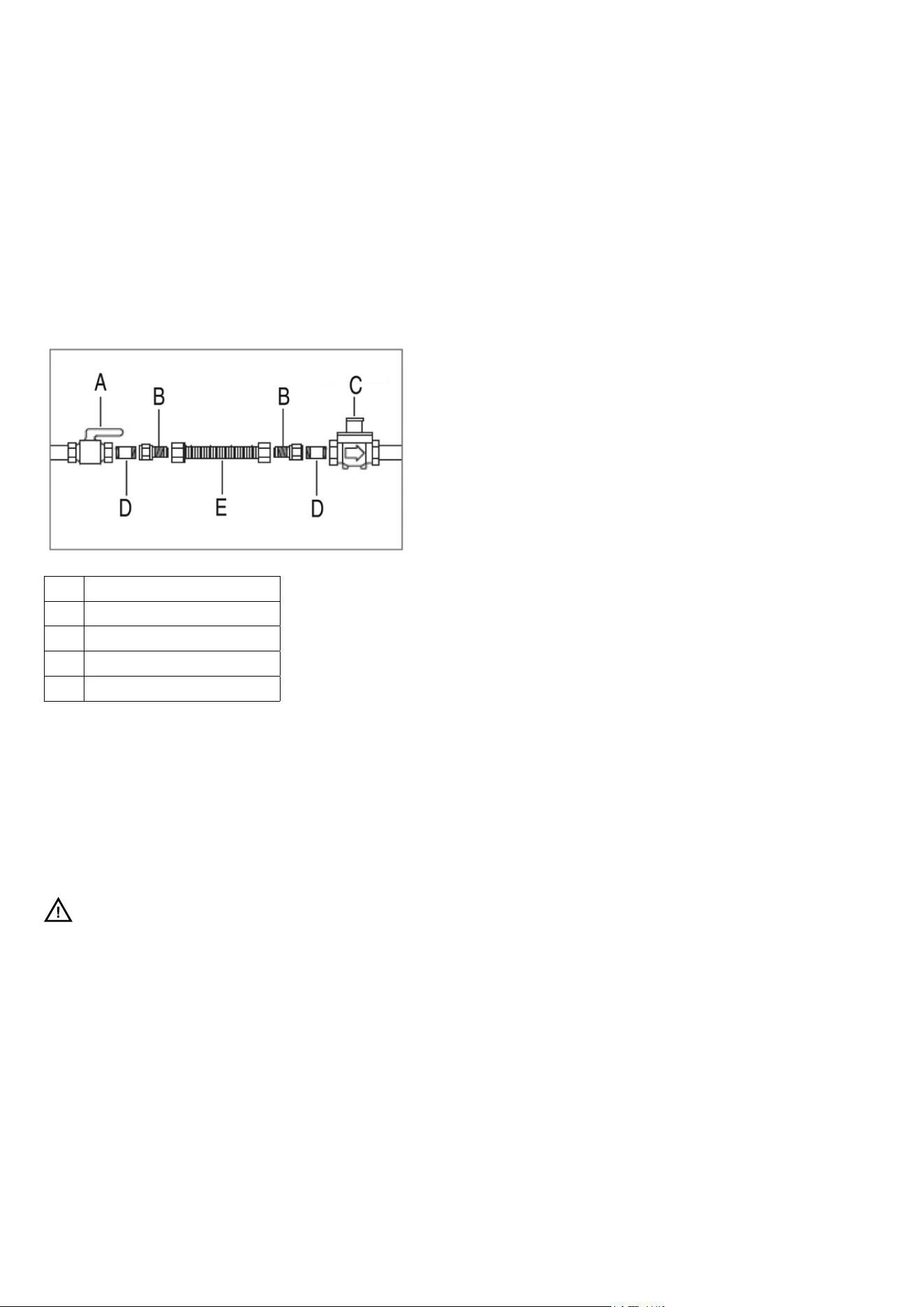
GAS SUPPLY CONNECTION
Assemble the flexible metal connector from the gas supply
pipe to the gas pressure regulator. You will need to determine
the fittings required, depending on the size of your gas supply
line, flexible metal connector and shut-off valve. Refer to the
illustration below. Use a pipe joint compound made for use with
natural and LP gas. If a flexible metal connector is used, be sure
the tubing is not kinked.
Open the shut-off valve in the gas supply line. Wait a few
minutes for the gas to move through the line.
A Shut-o valve
B Adapter
C Gas pressure regulator
D Nipple
E Flexible metal connector
Gas leak testing
Use a brush and liquid detergent to test all gas connections for
leaks. Bubbles around connections will indicate a leak. If a leak
appears, shut off the gas supply and adjust connections. Then
check connections again. Clean the detergent solution from
the cooktop.
WARNING
Never test for a gas leak with a match or other ame
16
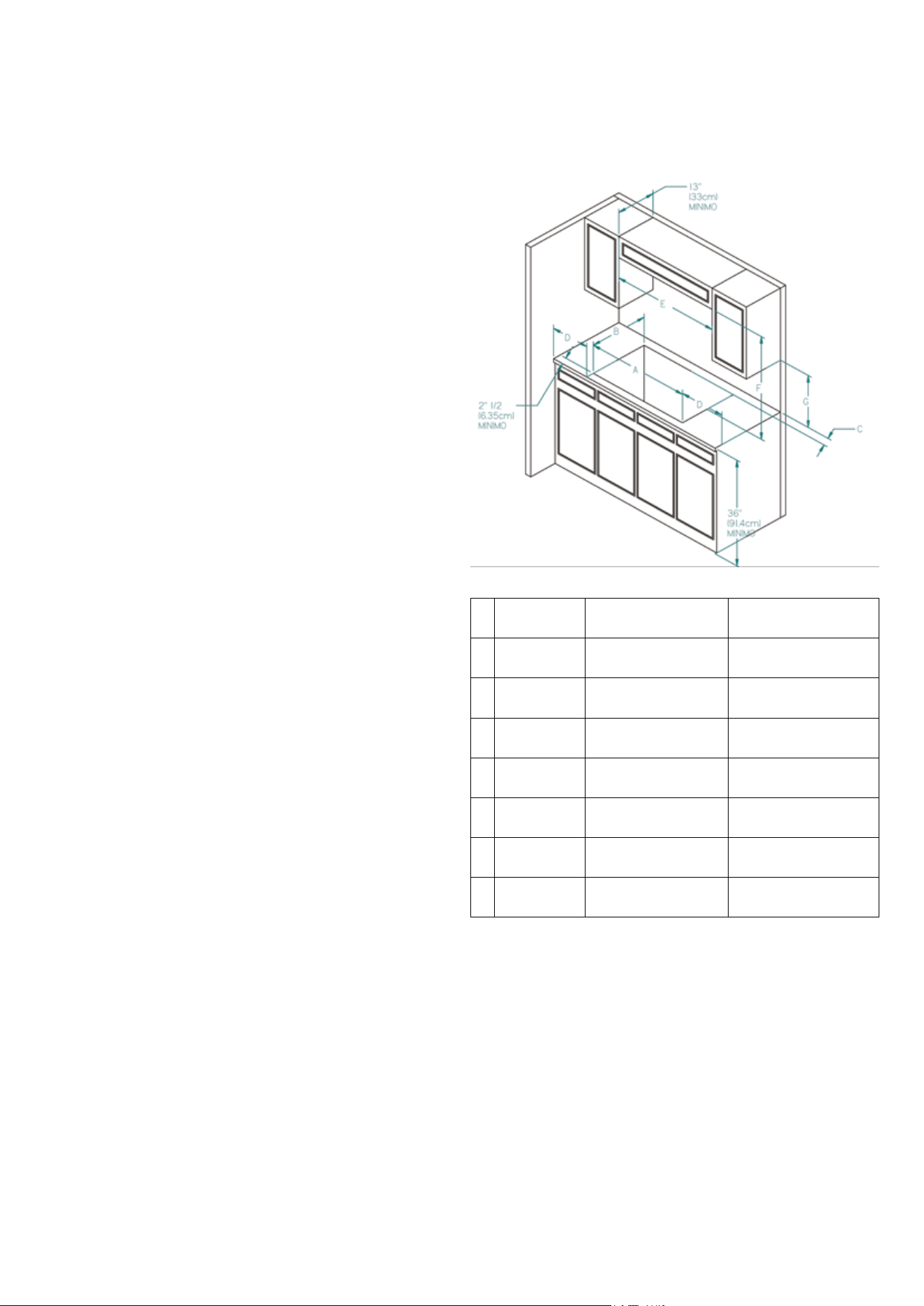
INSTALLATION
UHC(P/PT)75.., UHC(P/PT/PM/PMT)95.., UHC(P/PT/PM/PMT)125..,
Proximity to Side Cabinet Installation
The cooktop may be installed directly to existing base cabi-
nets. The cooktop CANNOT be installed directly adjacent to
sidewalls, tall cabinets, tall appliances, or other side vertical
surfaces above 36” (91.4 cm) high. There must be a minimum
of 8” (20.3 cm) side clearance from the cut-out to such combu-
stible surfaces above the 36” (91.4 cm) counter height. Within
the 8” (20.3 cm) side clearance to combustible vertical sur-
faces above 36” (91.4 cm), the maximum wall cabinet depth
must be 13” (33.0 cm) and wall cabinets within this 8” (20.3
cm) side clearance must be 18” (45.7 cm) above the 36” (91.4
cm) high countertop. Wall cabinet above the cooktop must be
a minimum of 36” (91.4 cm) above the countertop. This mini-
mum height requirement does not apply if a rangehood is in-
stalled over the cooking surface.
Minimum Clearances from Adjacent
Combustible Construction
Above countertop 36” (91.4 cm) minimum
Side 8” (20.3 cm)
Rear 3” (7.62 cm) min.
Wall cabinets no deeper than 13” (33.0 cm)
Must be minimum 18” (45.7 cm) above countertop
Wall cabinets directly above the product must be minimum 36”
(91.4 cm) above the countertop
UHC
(P/PT)75...
UHC
(P/PT/PM/PMT)95...
UHC
(P/PT/PM/PMT)125...
A 26 29/64’
(67.2 cm)
33 55/64’
(86.0 cm)
44 7/8’
(114.0 cm)
B 19 19/64’
(49 cm)
19 19/64’
(49 cm)
19 19/64’
(49 cm)
C MIN. 3’
(7.62 cm)
MIN. 3’
(7.62 cm)
MIN. 3’
(7.62 cm)
D MIN. 8’
(20.3 cm)
MIN. 8’
(20.3 cm)
MIN. 8’
(20.3 cm)
E MIN. 28 1/2
(72.4 cm)
MIN. 35 1/2
(90.2 cm)
MIN. 46 1/2
(118.1 cm)
F MIN. 36’
(91.4 cm)
MIN. 36’
(91.4 cm)
MIN. 36’
(91.4 cm)
G MIN. 18’
(47.7 cm)
MIN. 18’
(47.7 cm)
MIN. 18’
(47.7 cm)
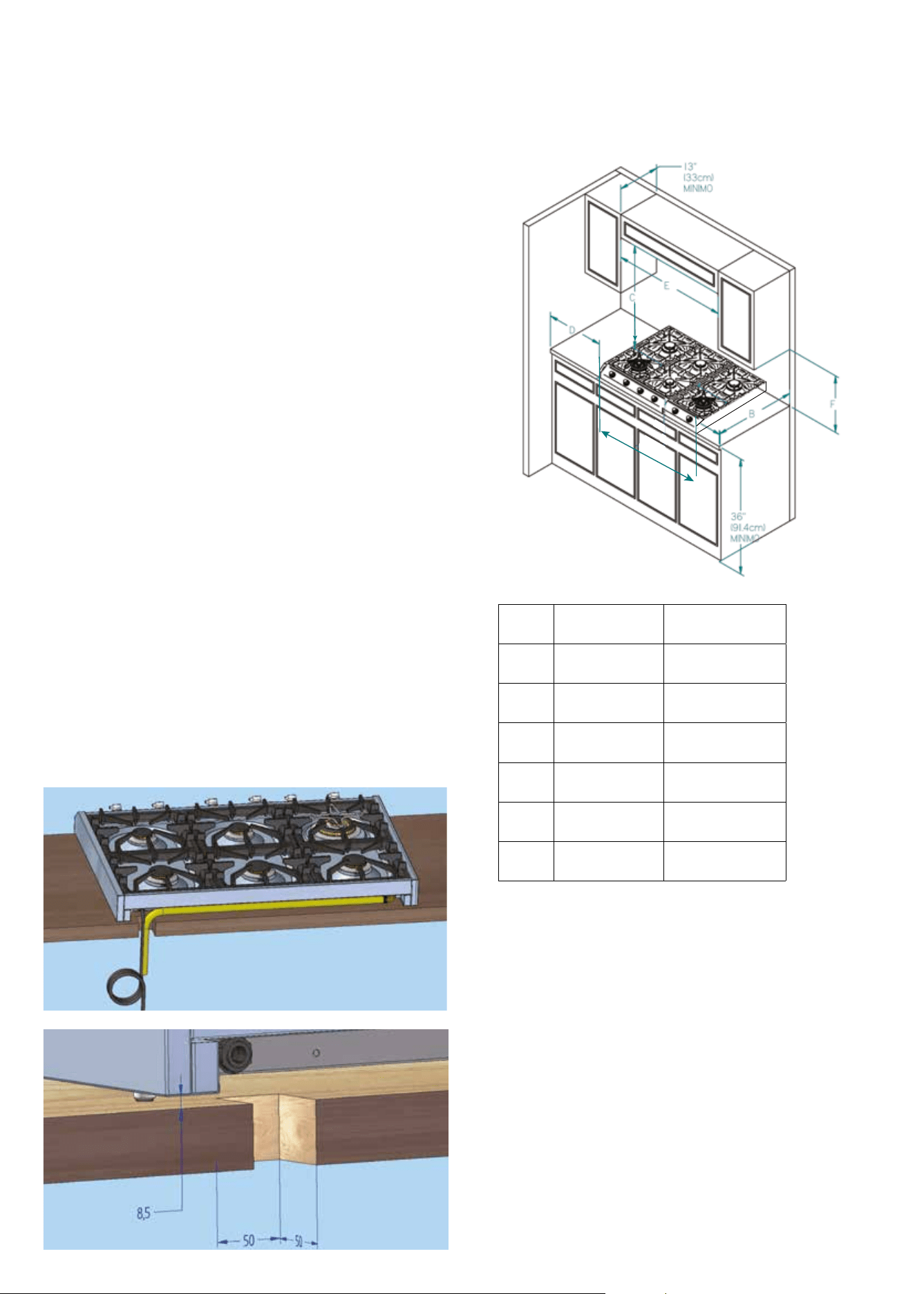
17
Proximity to Side Cabinet Installation
The cooktop may be installed directly to existing base cabi-
nets. The cooktop CANNOT be installed directly adjacent to
sidewalls, tall cabinets, tall appliances, or other side vertical
surfaces above 36” (91.4 cm) high. There must be a minimum
of 8” (20.3 cm) side clearance from the cooktop to such com-
bustible surfaces above the 36” (91.4 cm) counter height.
Within the 8” (20.3 cm) side clearance to combustible vertical
surfaces above 36” (91.4 cm), the maximum wall cabinet depth
must be 13” (33.0 cm) and wall cabinets within this 8” (20.3
cm) side clearance must be 18” (45.7 cm) above the 36” (91.4
cm) high countertop.
The maximum wall cabinet depth must be 13” (33.0 cm) and
wall cabinets within this 8” (20.3 cm) side clearance must be
18” (45.7 cm) above the 36” (91.4 cm) high countertop
Wall cabinet above the cooktop must be a minimum of 36”
(91.4 cm) above the burner graters. This minimum height re-
quirement does not apply if a rangehood is installed over the
cooking surface.
Minimum Clearances from Adjacent
Combustible Construction
Above countertop 36” (91.4 cm) minimum
Side 8” (20.3 cm)
Wall cabinets no deeper than 13” (33.0 cm)
Must be minimum 18” (45.7 cm) above countertop
Wall cabinets directly above the product must be minimum 36”
(91.4 cm) above the burner grates
A hole of 1’’ 31/32 (5 cm x 5 cm) must be done on the top for
power cable and gas conduit as shown in picture
INSTALLATION
UHCP965.., UHCP1265.., UHCP36..., UHCP48..,
A
UHC P 965..
UHC P 36...
UHC P 1265...
UHC P 48...
A 35 7/8’
(91.1 cm)
47 7/8’
(121.6 cm)
B 25 19/32’
(65 cm)
25 19/32’
(65 cm)
C MIN. 36’
(91.4 cm)
MIN. 36’
(91.4 cm)
D MIN. 8’
(20.3 cm)
MIN. 8’
(20.3 cm)
E MIN. 36’
(91.4 cm)
MIN. 48’
(121.9 cm)
F MIN. 18’
(47.7 cm)
MIN. 18’
(47.7 cm)
18
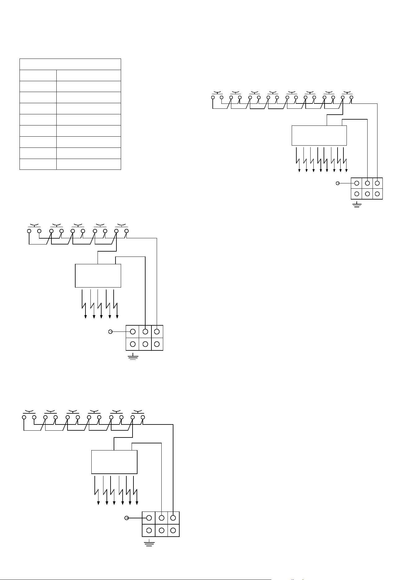
WIRING DIAGRAM
LED Display L3
KEYS
33 White
45 Green
00 Black
SP Ignition electrode
MA Ignition microswitch
AA Ignition trasformer
M Terminal board
F Phase
N Neutral
5 BURNERS
UHC (P/PT) 75... UHC (P/PT/PM/PMT) 95...
00 33
AA
MA MA
SP
33
00
33
33
MA MA
3333
333333
MA
33
33
5 BURNERS
00 33
AA
MA MA
SP
33
00
22
33
MA MA
3333
333333
MA
33
33
AA
MA MA
SP
33
33
33
33
8 BURNERS
MA
33
33
M
45
K14
N
F
M
45
K14
N
F
00
00 33
AA
MA MA
SP
33
00
33
33
MA MA
3333
333333
MA MA
3333
3333
6 BURNERS
M
45
K14
N
F
00 33
AA
MA MA
SP
33
00
33
33
MA MA
3333
333333
MA MA
3333
3333
8 BURNERS
M
45
K14
N
F
MA MA
33
33
6 BURNERS
UHC P 36... UHC (P/PT/PM/PMT) 125...
00 33
AA
MA MA
SP
33
00
33
33
MA MA
3333
333333
MA
33
33
5 BURNERS
00 33
AA
MA MA
SP
33
00
22
33
MA MA
3333
333333
MA
33
33
AA
MA MA
SP
33
33
33
33
8 BURNERS
MA
33
33
M
45
K14
N
F
M
45
K14
N
F
00
00 33
AA
MA MA
SP
33
00
33
33
MA MA
3333
333333
MA MA
3333
3333
6 BURNERS
M
45
K14
N
F
00 33
AA
MA MA
SP
33
00
33
33
MA MA
3333
333333
MA MA
3333
3333
8 BURNERS
M
45
K14
N
F
MA MA
33
33
8 BURNERS
UHC P 1265... UHC P 48...
00 33
AA
MA MA
SP
33
00
33
33
MA MA
3333
333333
MA
33
33
5 BURNERS
00 33
AA
MA MA
SP
33
00
22
33
MA MA
3333
333333
MA
33
33
AA
MA MA
SP
33
33
33
33
8 BURNERS
MA
33
33
M
45
K14
N
F
M
45
K14
N
F
00
00 33
AA
MA MA
SP
33
00
33
33
MA MA
3333
333333
MA MA
3333
3333
6 BURNERS
M
45
K14
N
F
00 33
AA
MA MA
SP
33
00
33
33
MA MA
3333
333333
MA MA
3333
3333
8 BURNERS
M
45
K14
N
F
MA MA
33
33
19
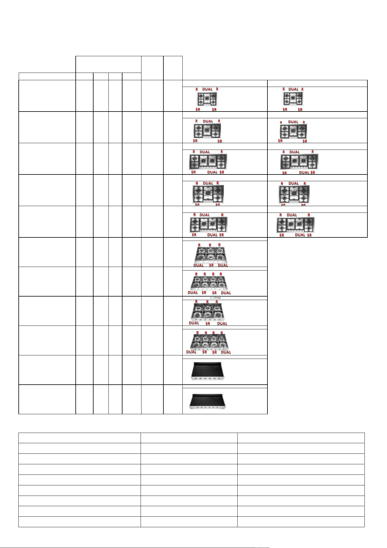
ELECTRICAL AND GAS POWER TABLE
COMP L ETE
APP L IANCE
GAS RATING [Btu /h ]
COMP L ETE
APP L IANCE
ELECTRIC RATED
INPUT [W]
MODEL
SR
7000 Btu
R
10500 Btu
DUAL
18000 Btu
DUAL
22000 Btu
UHCP75 - UHCP75N
wi th flat frame
UHCPT75 - UHCPT75N
BUILT-IN GAS COOKTOP
UHC(P/PT)75
UHC(P/PT)75 N
2 2 1 53000 1
UHCP95 - UHCP95(F/FF) - UHCP95N - UHCP95(F/FF)N
wi th flat frame
UHCPT95 - UHCPT95(F/FF) - UHCPT95N - UHCPT95(F/FF)N
BUILT-IN GAS COOKTOP
UHC(P/PT)95 - UHC(P /PT)95 (F/ FF)
UHC(P/PT)95N - UHC(P /PT)9 5 (F/FF)N
2 2 1 53000 1
UHCP125 - UHCP125(F/FF) - UHCP125N - UHCP125(F/FF)N
wi th flat frame
UHCPT125 - UHCPT125(F/FF) - UHCPT125N - UHCPT125(F/FF)N
BUILT-IN GAS COOKTOP
UHC(P/PT)125 - UHC(P /PT)1 2 5 (F/FF)
UHC(P/PT)125N - UHC(P /PT)1 2 5 (F/FF)N
2 2 2 71000 1
UHCPM95 - UHCPM95(F/FF)
wi th flat frame
UHCPMT95 - UHCPMT95(F/FF)
BUILT-IN GAS COOKTOP
UHC(PM/PMT)95 - UHC(P M/PMT)95 (F/ FF)
2 2 1 53000 1
UHCPM125 - UHCPM125(F/FF)
wi th flat frame
UHCPMT125 - UHCPMT125(F/FF)
BUILT-IN GAS COOKTOP
UHC(PM/PMT)125 - UHC(P M/PMT)1 2 5 (F/FF)
2 2 2 71000 1
UHCP965(6/F) - UHCP965(6/F)N
FREE STANDING GAS HOB
UHCP965(6/F)
UHCP965(6/F)N
1 3 2 82500 1
UHCP1265(8/F) - UHCP1265(8/F)N
FREE STANDING GAS HOB
UHCP1265(8/F)
UHCP1265(8/F)N
2 4 2 100000 1
UHCP36(6/F) - UHCP36(6/F)N
FREE STANDING GAS HOB
UHCP3 6(6/F)
UHCP3 6(6/F)N
1 3 2 82500 1
UHCP48(8/F) - UHCP48(8/F)N
FREE STANDING GAS HOB
UHCP4 8(8/F)
UHCP4 8(8/F)N
2 4 2 100000 1
UHCPI36 - UHCPI36N
FREE STANDING INDUCTION HOB
UHCPI366
UHCPI366N
11520
UHCPI48 - UHCPI48N
FREE STANDING INDUCTION HOB
UHCPI486
UHCPI486N
11520
BURNERS
Injectors for a device installed at an altitude above 2000 ft
Burner Gas Orifice size [1/100] mm
SR NATURAL (A) 117
R NATURAL (A) 141
DUAL (18000 Btu/h) NATURAL (A) 74+185
DUAL (22000 Btu/h) NATURAL (A) 74+200
SR PROPANE (E) 75
R PROPANE (E) 92
DUAL (18000 Btu/h) PROPANE (E) 50+117
DUAL (22000 Btu/h) PROPANE (E) 50+120

ilve.com
ILVE S.p.A Via Antoniana, 100 — 35011 — Campodarsego (PD) Italy
T. +39 049 9200990 / Email: [email protected]
cod. EI33960760000EN 06/2025