Installaon Instrucons and
Use & Care Guide
Keep this manual in the pocket on heater for future reference whenever maintenance, adjustment or service is required.
Retain your original receipt as proof of purchase.
Read this manual and the labels on the water heater before
you install, operate, or service it. This water heater is designed
for Natural Gas operaon only. If you have diculty following
the direcons, or aren’t sure you can safely and properly do
any of this work yourself:
• Call our Technical Assistance Hotline which is listed on your warranty.
We can help you with installaon, operaons, troubleshoong, or
maintenance. Before you call, write down the model and serial number
from the water heater’s data plate.
• Incorrect installaon, operaon, or service can damage the water
heater, your house and other property, and present risks including re,
scalding, electric shock, and explosion, causing serious injury or death.
100385425_2000839619November 2025
Do not store or use gasoline or other ammable vapors
and liquids in the vicinity of this or any other appliance.
WHAT TO DO IF YOU SMELL GAS
• Do not try to light any appliance.
• Do not touch any electrical switch; do not use any
phone in your building.
• Immediately call your gas supplier from a neighbor’s
phone. Follow the gas supplier’s instrucons.
• If you cannot reach your gas supplier, call the re de-
partment.
Installaon and service must be performed by a qualied
installer, service agency or the gas supplier.
WARNING: If the informaon in these instrucons
is not followed exactly, a re or explosion may
result causing property damage, personal injury or
death.
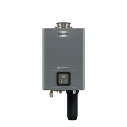
Non-Condensing
Residenal Gas
Tankless Water Heater
Residenal On-Demand Gas Tankless Water Heater
(X3® TECHNOLOGY available on some models)
LOW LEAD
C
O
NTENT
MODELS:
TI-180X3-N TO-180X3-N
TI-180B-N TO-180B-N
TI-199X3-N TO-199X3-N
TI-199B-N TO-199B-N
NATURAL GAS ONLY
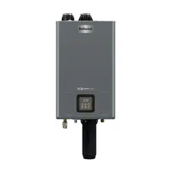
TI INDOOR MODEL
(X3® CONFIGURATION)
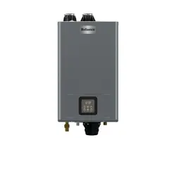
TO OUTDOOR MODEL
(X3® CONFIGURATION)

2 • Residenal Non-Condensing Gas Tankless Water Heater Use and Care Guide
TABLE OF CONTENTS
WATER HEATER BASICS ................................................................................................... 4
Component Overview (Indoor Model) ....................................................................................................................................... 4
Component Overview (Outdoor Model) .................................................................................................................................... 5
Typical Installaon (Indoor Model) ............................................................................................................................................ 6
Typical Installaon (Outdoor Model) ......................................................................................................................................... 7
Dimensions (Indoor Model) ....................................................................................................................................................... 8
Dimensions (Outdoor Model) .................................................................................................................................................... 9
Supply Connecons .................................................................................................................................................................. 10
Product Specicaon and Technical Data (Indoor Model) ....................................................................................................... 11
Product Specicaon and Technical Data (Outdoor Model) .................................................................................................... 12
IMPORTANT SAFETY INFORMATION ............................................................................. 13
RISKS DURING INSTALLATION AND MAINTENANCE ................................................................................................................. 14
RISKS DURING OPERATION ...................................................................................................................................................... 14
GETTING STARTED ........................................................................................................ 16
Read Before Installaon .......................................................................................................................................................... 16
Recommended Tools and Materials ......................................................................................................................................... 19
Recommended Accessories ...................................................................................................................................................... 19
Included Items ......................................................................................................................................................................... 20
Available Accessories ............................................................................................................................................................... 21
INSTALLATION .............................................................................................................. 22
Installaon Environment ......................................................................................................................................................... 22
Unit Clearances........................................................................................................................................................................ 22
Mounng the Water Heater (Indoor Model) ........................................................................................................................... 23
Mounng the Water Heater (Outdoor Model) ........................................................................................................................ 23
Venng (Indoor Model) ........................................................................................................................................................... 24
Replacing a Water Heater Using the Exisng Vent System ...................................................................................................... 25
Vent Length and Number of Elbows Allowed .......................................................................................................................... 25
Venng Illustraons ................................................................................................................................................................. 27
Clearances for Sidewall Terminaons (Indoor Model) ............................................................................................................. 30
Clearances for Mul-Unit Water Heaters (Outdoor Model) .................................................................................................... 31
Clearances for Rooop Terminaons ....................................................................................................................................... 32
Gas Supply and Gas Pipe Sizing ............................................................................................................................................... 33
Water Connecons .................................................................................................................................................................. 35

Residenal Non-Condensing Gas Tankless Water Heater Use and Care Guide • 3
TABLE OF CONTENTS
X3® Technology ........................................................................................................................................................................ 36
Pressure Relief Valve ................................................................................................................................................................ 37
Recirculaon ............................................................................................................................................................................ 38
Electrical Connecons .............................................................................................................................................................. 40
Accessory Connecons............................................................................................................................................................. 41
Cascade System ....................................................................................................................................................................... 44
OPERATION .................................................................................................................. 46
FOR YOUR SAFETY, READ BEFORE OPERATING ........................................................................................................................ 46
Start-Up Instrucons ................................................................................................................................................................ 46
Shut-Down Instrucons ........................................................................................................................................................... 46
Emergency Shut-Down ............................................................................................................................................................ 46
User Interface Module (UIM) & Remote Controller Display Overview ..................................................................................... 48
Temperature Sengs............................................................................................................................................................... 49
Conguraon Mode (C Mode) ................................................................................................................................................. 50
Cascade Conguraon............................................................................................................................................................. 51
Unit Conversion Mode ............................................................................................................................................................. 51
MAINTENANCE ............................................................................................................ 52
Regular Maintenance .............................................................................................................................................................. 52
Freeze Protecon System ......................................................................................................................................................... 52
Unit Draining & Power Outage (Freeze Protecon) ................................................................................................................. 53
Inlet Water Filter ...................................................................................................................................................................... 53
TROUBLESHOOTING ..................................................................................................... 54
General Troubleshoong ......................................................................................................................................................... 54
Error Codes .............................................................................................................................................................................. 56
Fault Analysis of Error Codes ................................................................................................................................................... 57
COMPONENTS ............................................................................................................. 62
Component View (Indoor Model) ............................................................................................................................................ 62
Component View (Outdoor Model).......................................................................................................................................... 64
Components List ...................................................................................................................................................................... 66
APPENDIX .................................................................................................................... 67
Electrical Wiring Diagram ........................................................................................................................................................ 67
Flow Rate Capacity Chart ........................................................................................................................................................ 68
NOTES .......................................................................................................................... 69
4 • Residenal Non-Condensing Gas Tankless Water Heater Use and Care Guide
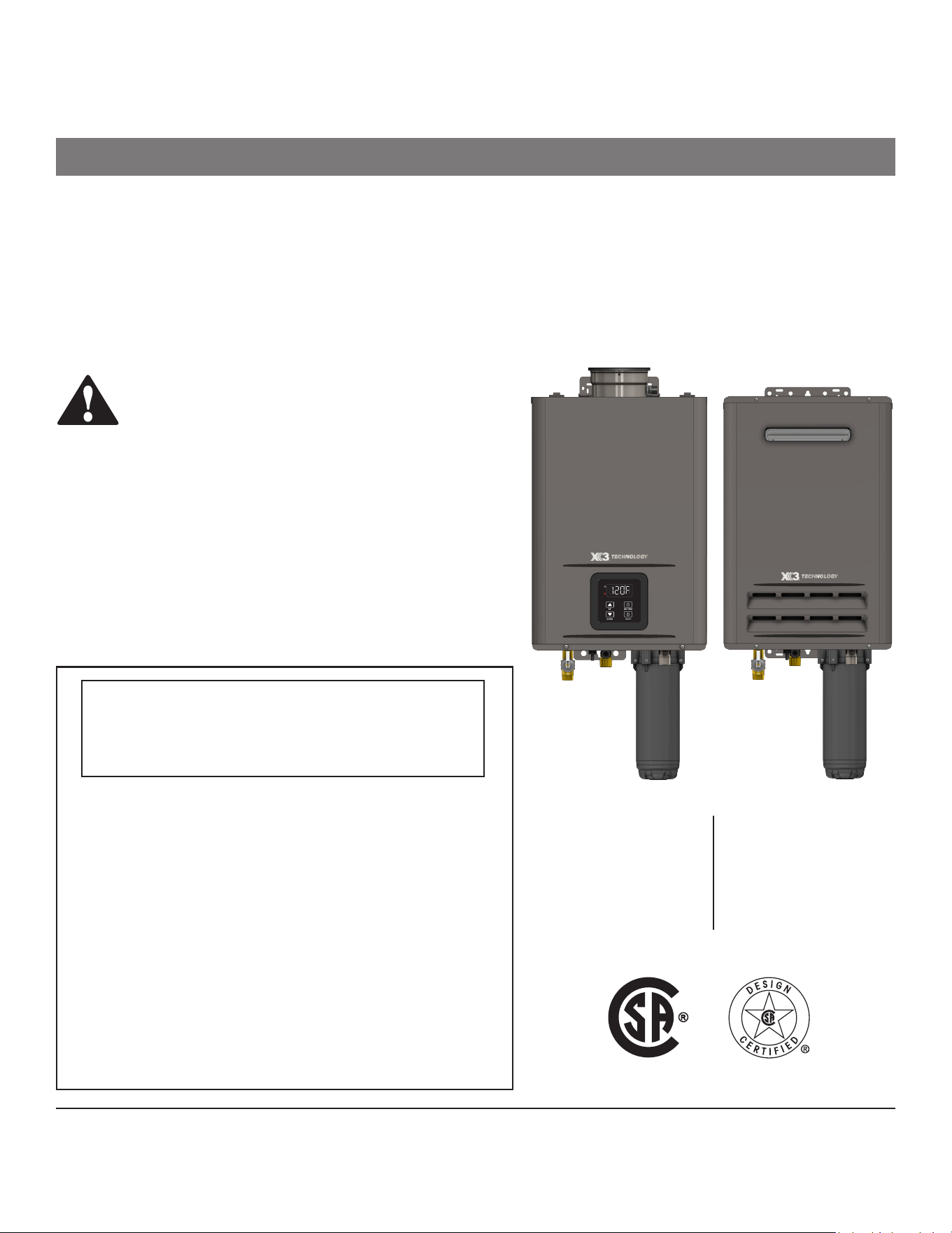
WATER HEATER BASICS
Component Overview (Indoor Model)
Gas Valve
Printed Circuit Board (PCB)
Gas Manifold
Heat Exchanger
Flow Sensor
Control Valve
Assembly
Fan Motor Assembly
Water Bypass Valve
Ignitor &
Flame Rod Assembly
Concentric Vent
(3" Exhaust / 5" Air Intake)
Condensate Drain
Burner Assembly
User Interface Module
(UIM)
removed for clarity
X3
®
Cartridge
Base (B Model) Configuration*
X3® Technology (X3® Model):
This water heater is equipped with X3® Scale Prevenon Technology to inhibit scale formaon within the heat exchanger tubing of this unit.
Part of the X3® Technology’s an-scale protecon comes from the special X3® Cartridge media. The X3® Cartridge must be installed into the
manifold located on the underside of the heater cabinet prior to operaon of the unit. X3® Scale Prevenon Technology reduces the formaon
of scale in the heat exchanger, extending the operang life of the unit in typical potable water installaons. Specic water condions may
impact the eciency of X3®, such as excessive iron or manganese levels. The maximum allowable limit of iron is 0.3 mg/l or 0.3 ppm and
manganese is 0.05 mg/l or 0.05 ppm. Levels greater than these will reduce the eecveness of the X3®. Refer to the guidelines below and
consult a water quality expert to determine if your water is within acceptable X3® and EPA guidelines.
NOTICE: Pressure Relief Valve supplied in the box with this model.
*B Model: The base non-condensing model with no integrated X3® cartridge.
NOTICE: Pressure Relief Valve will need to be eld supplied with this model.
Residenal Non-Condensing Gas Tankless Water Heater Use and Care Guide • 5
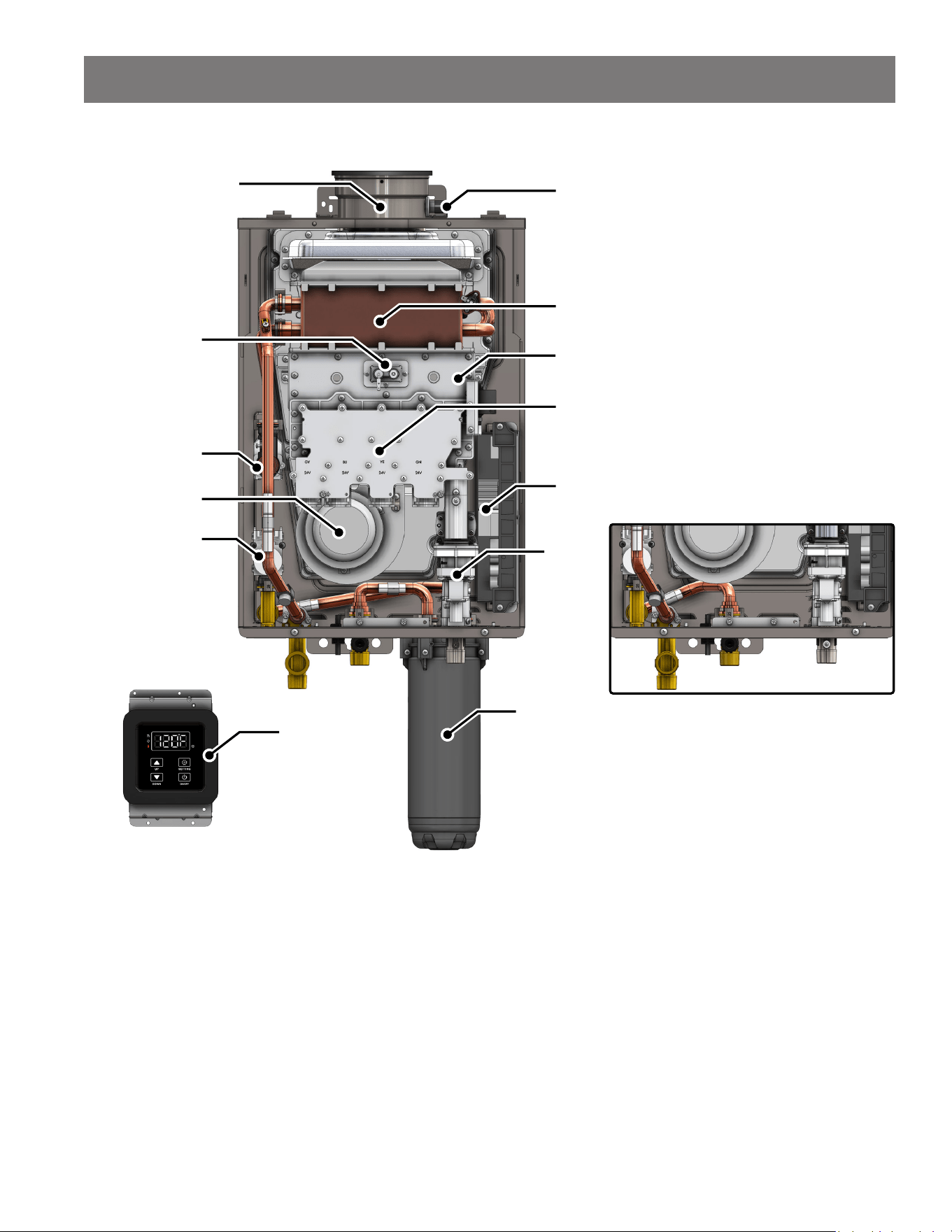
Component Overview (Outdoor Model)
Printed Circuit Board (PCB)
Gas Manifold
Heat Exchanger
Flow Sensor
Control Valve
Assembly
Fan Motor Assembly
Water Bypass Valve
Ignitor &
Flame Rod Assembly
Burner Assembly
Remote Controller
X3
®
Cartridge
Gas Valve
Base (B Model) Configuration*
X3® Technology (X3® Model):
This water heater is equipped with X3® Scale Prevenon Technology to inhibit scale formaon within the heat exchanger tubing of this unit.
Part of the X3® Technology’s an-scale protecon comes from the special X3® Cartridge media. The X3® Cartridge must be installed into the
manifold located on the underside of the heater cabinet prior to operaon of the unit. X3® Scale Prevenon Technology reduces the formaon
of scale in the heat exchanger, extending the operang life of the unit in typical potable water installaons. Specic water condions may
impact the eciency of X3®, such as excessive iron or manganese levels. The maximum allowable limit of iron is 0.3 mg/l or 0.3 ppm and
manganese is 0.05 mg/l or 0.05 ppm. Levels greater than these will reduce the eecveness of the X3®. Refer to the guidelines below and
consult a water quality expert to determine if your water is within acceptable X3® and EPA guidelines.
NOTICE: Pressure Relief Valve supplied in the box with this model.
*B Model: The base non-condensing model with no integrated X3® cartridge.
NOTICE: Pressure Relief Valve will need to be eld supplied with this model.
WATER HEATER BASICS
6 • Residenal Non-Condensing Gas Tankless Water Heater Use and Care Guide
WATER HEATER BASICS
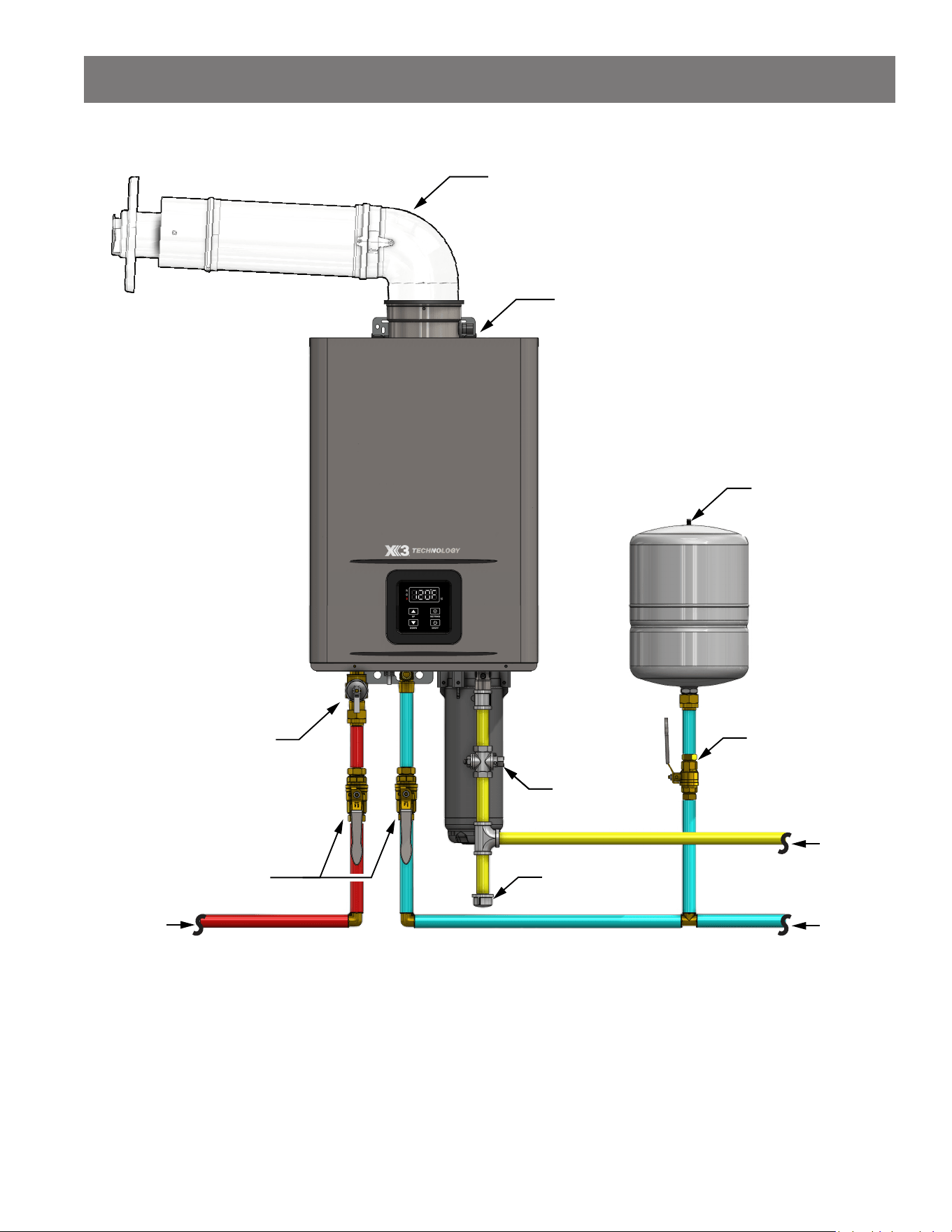
Typical Installaon (Indoor Model)
Concentric
Sidewall
Termination*
Expansion
Tank
Gas
Line
CWS
HWS
Gas
Shut-off Valve
Pressure Relief Valve
(Drain Line not
shown for clarity)
Drip Leg
Water
Shut-off
Valve
Condensate Drain
(Drain Line not
shown for clarity)
Water
Shut-off Valve
(Hot Water Supply) (Cold Water Supply)
*Sidewall terminaon shown. Vercal concentric vent terminaon is also available (see page 28).
Residenal Non-Condensing Gas Tankless Water Heater Use and Care Guide • 7
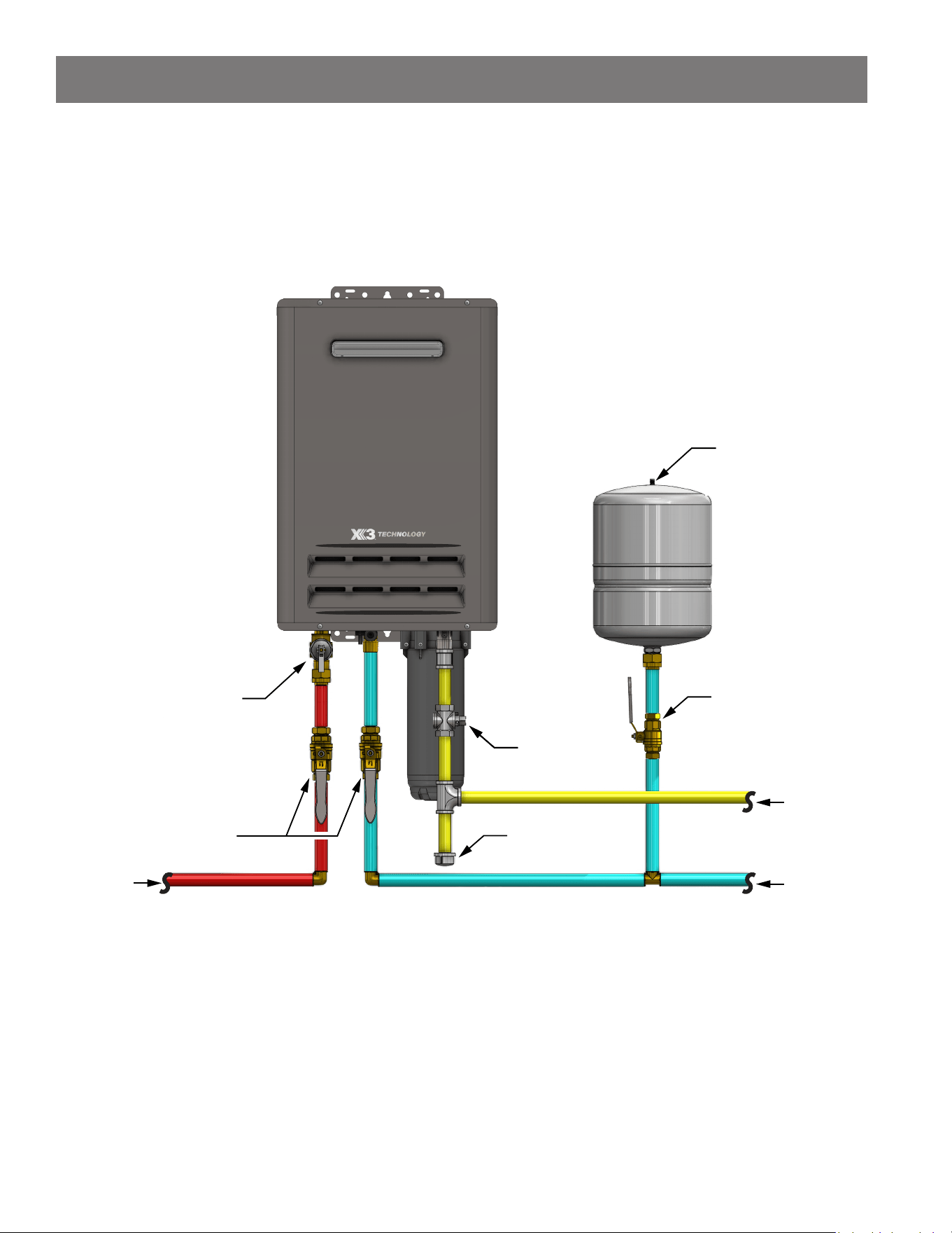
Typical Installaon (Outdoor Model)
Expansion
Tank
Gas
Line
CWS
HWS
Gas
Shut-off Valve
Pressure Relief Valve
(Drain Line not
shown for clarity)
Drip Leg
Water
Shut-off
Valve
Water
Shut-off Valve
(Hot Water Supply) (Cold Water Supply)
WATER HEATER BASICS
8 • Residenal Non-Condensing Gas Tankless Water Heater Use and Care Guide
WATER HEATER BASICS
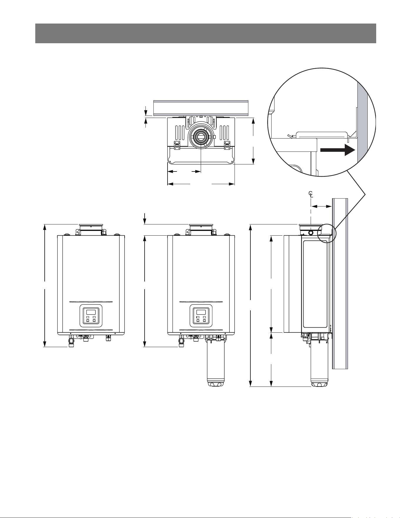
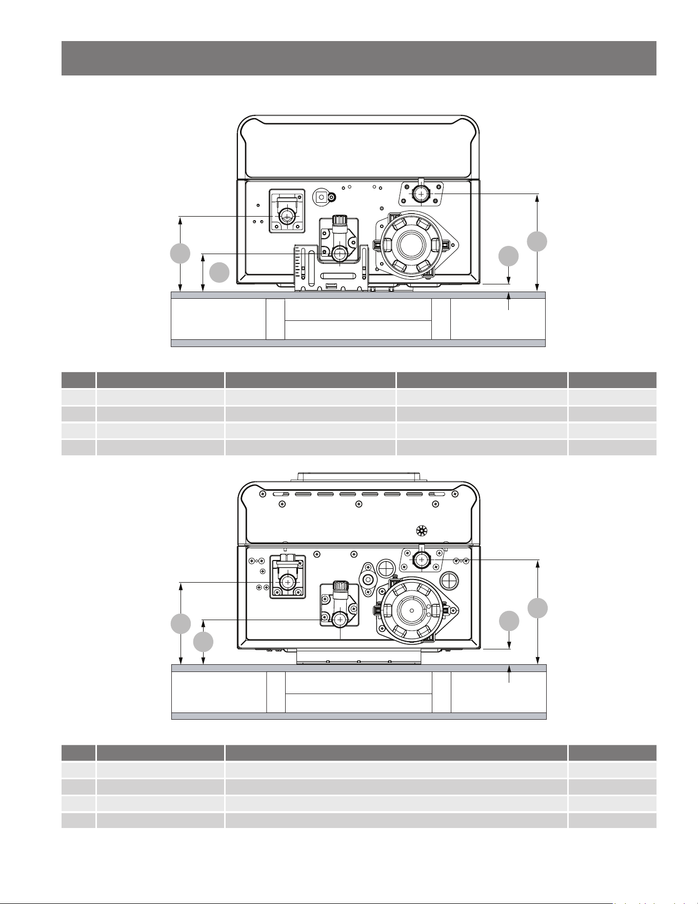
Dimensions (Indoor Model)
TOP & BOTTOM
BRACKETS
EXTENDABLE
UP TO 1.16"
B CONFIGURATION
X3
®
CONFIGURATION
25.39"
12.25"
10.63"
2.53"
WALL
WALL
15.51"
7.76"
MIN. 4.90"
MAX. 6.06"
MIN. 0.48"
MAX. 1.64"
22.10"
36.88"
27.92"
Residenal Non-Condensing Gas Tankless Water Heater Use and Care Guide • 9
WATER HEATER BASICS
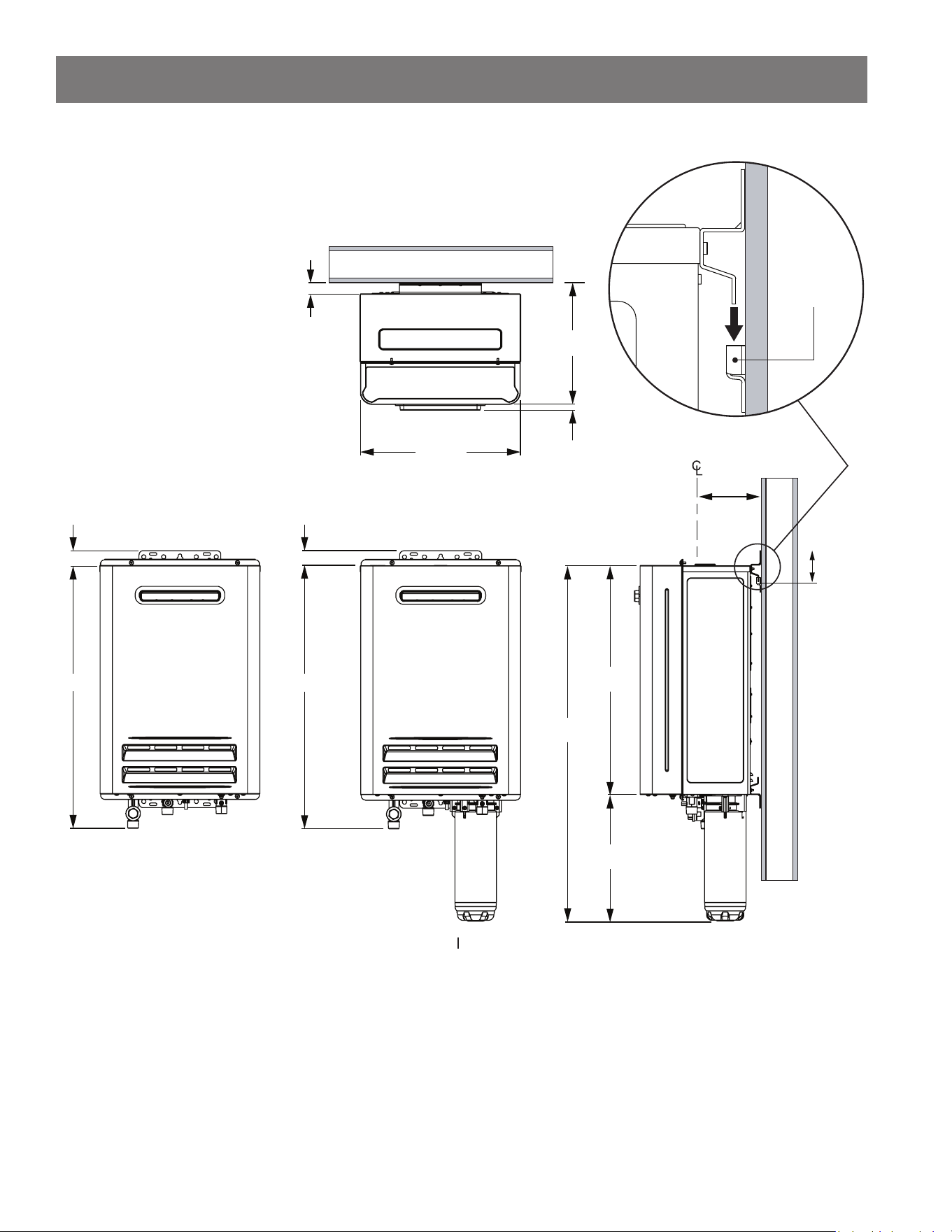
Dimensions (Outdoor Model)
B CONFIGURATION
X3
®
CONFIGURATION
25.40"
12.21"
11.65"
1.42"
WALL
WALL
15.51"
5.32"
0.98"
22.10"
34.31"
WATER
HEATER
WALL
MOUNT
2.97"
0.55"
25.40"
1.42"
10 • Residenal Non-Condensing Gas Tankless Water Heater Use and Care Guide
WATER HEATER BASICS
Supply Connecons
HOT
COLD
GAS
2
1
3
4
WALL
NOTICE: X3® Configuraon is shown.
INDOOR MODEL
Table 1: Supply Connecons (Indoor Model)
Item Descripon Dimension (Bracket Retracted) Dimension (Bracket Extended) Connecon Size
1 Hot Outlet 4.74 in 6.49 in 3/4" MNPT
2 Cold Inlet 2.38 in 4.13 in 3/4" MNPT
3 Wall Bracket 0.48 in 2.23 in N/A
4 Gas Inlet 6.15 in 7.90 in 3/4" MNPT
2
1
3
4
WALL
HOT
COLD
GAS
OUTDOOR MODEL
NOTICE: X3® Configuraon is shown.
Table 2: Supply Connecons (Outdoor Model)
Item Descripon Dimension Connecon Size
1 Hot Outlet 5.2 in 3/4" MNPT
2 Cold Inlet 2.84 in 3/4" MNPT
3 Wall Bracket 0.98 in N/A
4 Gas Inlet 6.62 in 3/4" MNPT
Residenal Non-Condensing Gas Tankless Water Heater Use and Care Guide • 11
WATER HEATER BASICS
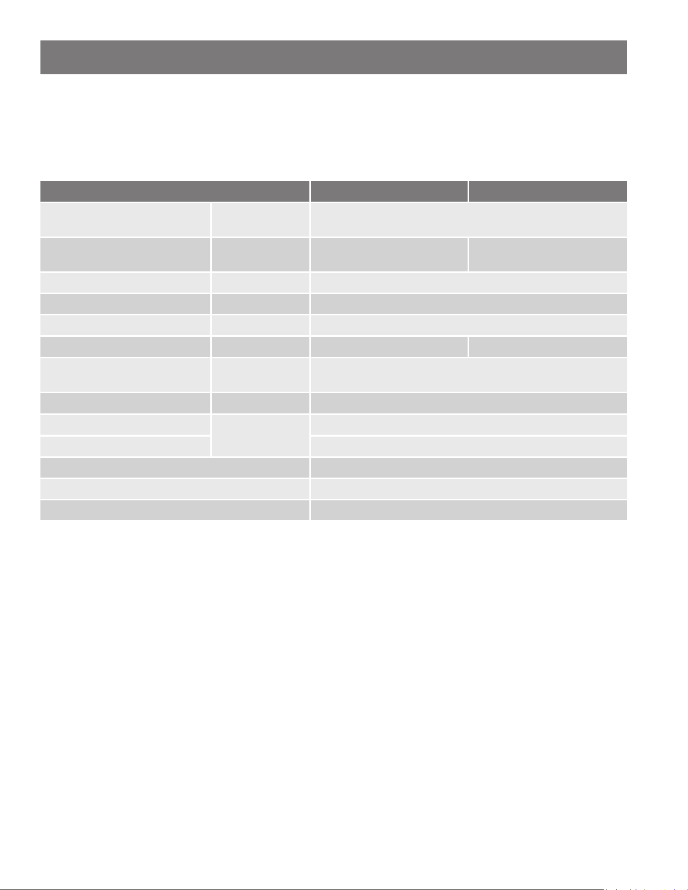
Product Specicaon and Technical Data (Indoor Model)
X3® Models: Comes with the X3® Scale Prevenon Technology cartridge and pressure relief valve.
B Models: The base non-condensing model with no integrated X3® cartridge.
Table 3: Specicaons
Model TI-180 TI-199
Natural Gas Input
(Minimum Operang Range)
BTU/H 10,000
Natural Gas Input
(Maximum Operang Range)
BTU/H 180,000 199,000
Gas Connecon 3/4" NPT
Water Connecons 3/4" NPT
Water Pressure* psi 15 - 150
Water Flow Rate** gpm 0.26 - 10.0, Acvaon Min: 0.4 0.26 - 10.5, Acvaon Min: 0.4
Natural Gas
Inlet Pressure
inch W.C.
Min: 4.0
Max: 10.5
Weight lbs. 65
Dimensions (X3® Models)
inch
W 15.51 x H 36.88 x D 10.63
Dimensions (B Models) W 15.51 x H 27.92 x D 10.63
Ignion Electronic Ignion
Electric Supply 120 V, 60 Hz, <5 A
Water Heater Category*** N/A
*40 psi or above is recommended for maximum ow.
**Minimum acvaon ow rate may increase if energy demand required is below the minimum input rang of the water heater.
***Water Heater Category - does not apply to Direct Vent water heaters and installaons in manufactured homes or outdoor
installaons.
NOTES:
• Check the rang plate to ensure that this product matches your specicaons. This water heater is designed for
Natural Gas only.
• The manufacturer reserves the right to disconnue, or change at any me, specicaons or designs without noce and with-
out incurring obligaon.

12 • Residenal Non-Condensing Gas Tankless Water Heater Use and Care Guide
Product Specicaon and Technical Data (Outdoor Model)
X3® Models: Comes with the X3® Scale Prevenon Technology cartridge and pressure relief valve.
B Models: The base non-condensing model with no integrated X3® cartridge.
Table 4: Specicaons
Model TO-180 TO-199
Natural Gas Input
(Minimum Operang Range)
BTU/H 10,000
Natural Gas Input
(Maximum Operang Range)
BTU/H 180,000 199,000
Gas Connecon 3/4" NPT
Water Connecons 3/4" NPT
Water Pressure* psi 15 - 150
Water Flow Rate** gpm 0.26 - 10.0, Acvaon Min: 0.4 0.26 - 10.5, Acvaon Min: 0.4
Natural Gas
Inlet Pressure
inch W.C.
Min: 4.0
Max: 10.5
Weight lbs. 64
Dimensions (X3® Models)
inch
W 15.51 x H 34.31 x D 11.65
Dimensions (B Models) W 15.51 x H 25.40 x D 11.65
Ignion Electronic Ignion
Electric Supply 120 V, 60 Hz, <5 A
Water Heater Category*** N/A
*40 psi or above is recommended for maximum ow.
**Minimum acvaon ow rate may increase if energy demand required is below the minimum input rang of the water heater.
***Water Heater Category - does not apply to Direct Vent water heaters and installaons in manufactured homes or outdoor
installaons.
NOTES:
• Check the rang plate to ensure that this product matches your specicaons. This water heater is designed for
Natural Gas only.
• The manufacturer reserves the right to disconnue, or change at any me, specicaons or designs without noce and with-
out incurring obligaon.
WATER HEATER BASICS
Residenal Non-Condensing Gas Tankless Water Heater Use and Care Guide • 13
IMPORTANT SAFETY INFORMATION
Read and follow all safety messages and instrucons in this
manual.
This is the safety alert symbol. It is used to alert you to
potenal physical injury hazards. Obey all safety messages
that follow this symbol to avoid possible property damage,
serious injury or death. Do not remove any permanent
instrucons, labels, or the rang plate from either the
outside of the water heater or on the inside of the access panels. Keep this
manual near the water heater.
WARNING! If the informaon in these instrucons is not followed
exactly, a re or explosion may result causing property damage, personal
injury or death. Do not store or use gasoline or other ammable vapors and
liquids in the vicinity of this or any other appliance.
An odorant is added by the gas supplier to the gas used by this water heater.
This odorant may fade over an extended period of me. Do not depend upon
this odorant as an indicaon of leaking gas. We recommend installing a fuel
gas and carbon monoxide detector.
This product is cered to comply with a maximum weighted average of
0.25% lead content as required in some areas.
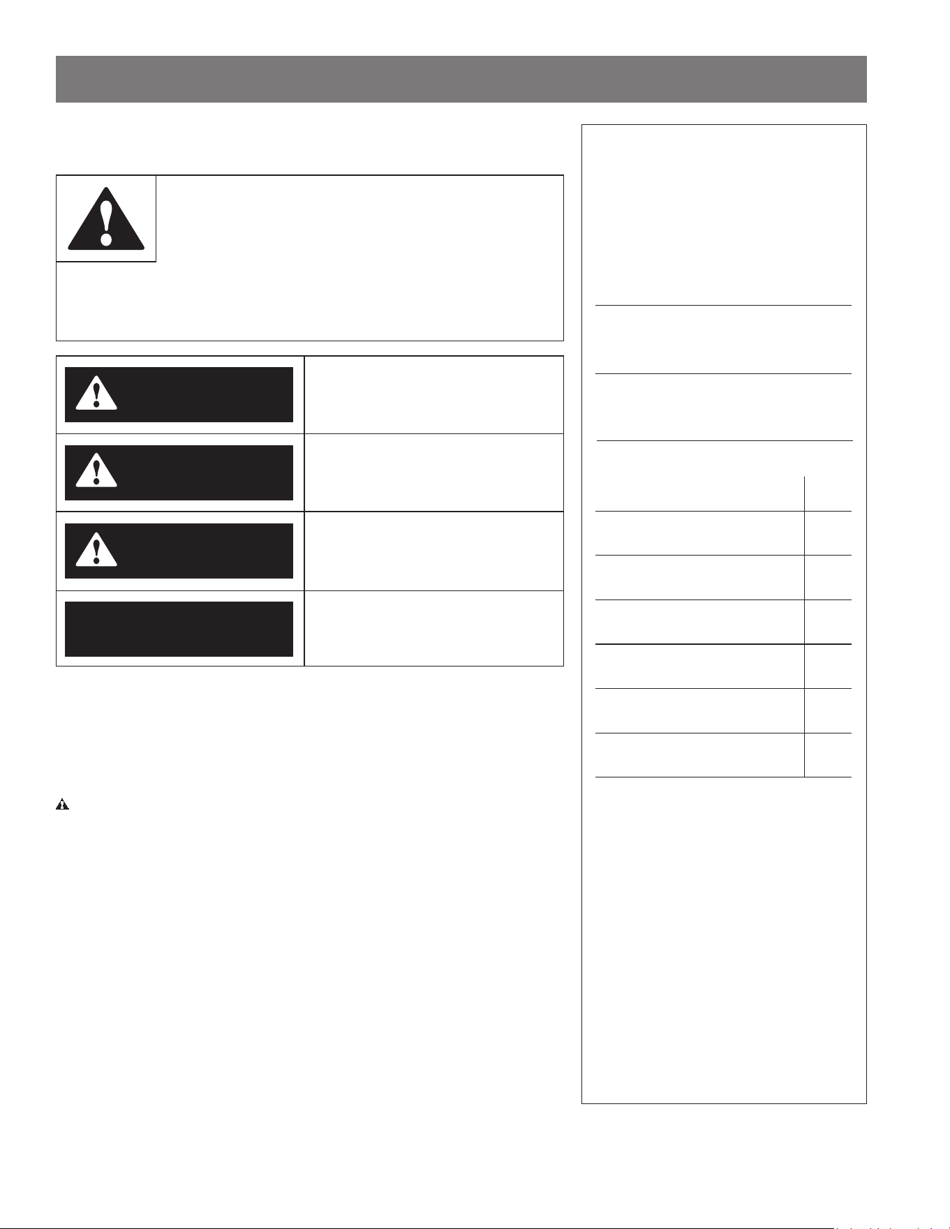
DANGER indicates a hazardous
situaon that, if not avoided, will
result in death or serious injury.
WARNING indicates a hazardous
situaon that, if not avoided, could
result in death or serious injury.
CAUTION indicates a hazardous
situaon that, if not avoided, could
result in minor or moderate injury.
NOTICE indicates pracces not
related to physical injury.
DANGER
WARNING
CAUTION
NOTICE
*Operate the Pressure Relief Valve
annually and inspect Pressure Relief
Valve every 2-4 years (see the label
on the Pressure Relief Valve for
maintenance schedule). If no label
is attached to the Pressure Relief
Valve, follow the instructions in the
Maintenance section of this manual.
See the Regular Maintenance section
for more information about maintaining
this water heater.
Important informaon to keep
Fill out this secon and keep this manual
in the pocket of the water heater for
reference.
Date Purchased:
Model Number:
Serial number:
Maintenance performed:* Date:
14 • Residenal Non-Condensing Gas Tankless Water Heater Use and Care Guide
To reduce the risk of property
damage, serious injury or death, read
and follow the precauons below,
all labels on the water heater, and
the safety messages and instrucons
throughout this manual.
RISKS DURING
INSTALLATION AND
MAINTENANCE
Liing Risk
WARNING! The
water heater is
heavy. Follow these
precauons to reduce the risk of
property damage, injuries from liing
or impact injuries from dropping the
water heater.
• Use at least two people to li the
water heater.
• Be sure you both have a good grip
before liing.
• Use an appliance dolly or hand truck
to move the water heater.
Explosion Risk
WARNING! This water
heater is designed for
Natural Gas operaon only. Refer
to the water heater’s rang plate.
Failure to follow these instrucons
can result in serious injury or death
from explosion, re or carbon
monoxide poisoning.
• DO NOT connect this Natural Gas
water heater to an L.P. gas supply.
• Use a new gas supply line approved
for Natural Gas that meets local and
state codes.
• Install a full port shut-o valve on
the gas supply line.
• Maintain the Pressure Relief Valve
properly. Follow the maintenance
instrucons provided by the manu-
facturer of the Pressure Relief Valve
(label aached to Pressure Relief
Valve). If no label is aached to the
Pressure Relief Valve, follow the
instrucons in the Pressure Relief
Valve Maintenance secon of this
manual. An explosion could occur if
the Pressure Relief Valve or dis-
charge pipe is blocked. Do not cap
or plug the Pressure Relief Valve or
discharge pipe.
Gas Pressure
WARNING! The Natural Gas
supply pressure must not exceed the
maximum supply pressure as stated
on the water heater’s rang plate.
Have a qualied person (licensed
plumber, gas company personnel,
or authorized service technician)
check for proper gas pressure. Gas
pressures exceeding the maximum
supply pressure as stated on the
water heater’s rang plate can
result in serious injury or death from
explosion or re.
RISKS DURING
OPERATION
Scalding Risk
This water heater
can make water hot
enough to cause
severe burns instantly, resulng in
severe injury or death.
• Feel water before bathing or show-
ering.
• To reduce the risk of scalding, install
Thermostac Mixing Valves (tem-
perature liming valves) at each
point-of-use. These valves automa-
cally mix hot and cold water to limit
the temperature at the tap. Mixing
valves are available at your local
plumbing supplier. Follow the man-
ufacturer’s instrucons for installa-
on and adjustment of the valves.
• Water temperatures over 125°F
can cause severe burns instantly
or death from scalding. The water
temperature is set at 120°F from the
factory to minimize any scalding risk.
Before bathing or showering, always
check the water temperature. Higher
temperatures increase the risk of
scalding, but even at 120°F, hot water
can scald. If you choose a higher
temperature seng, Thermostac
Mixing Valves located at each point-
of-use are parcularly important to
help avoid scalding.
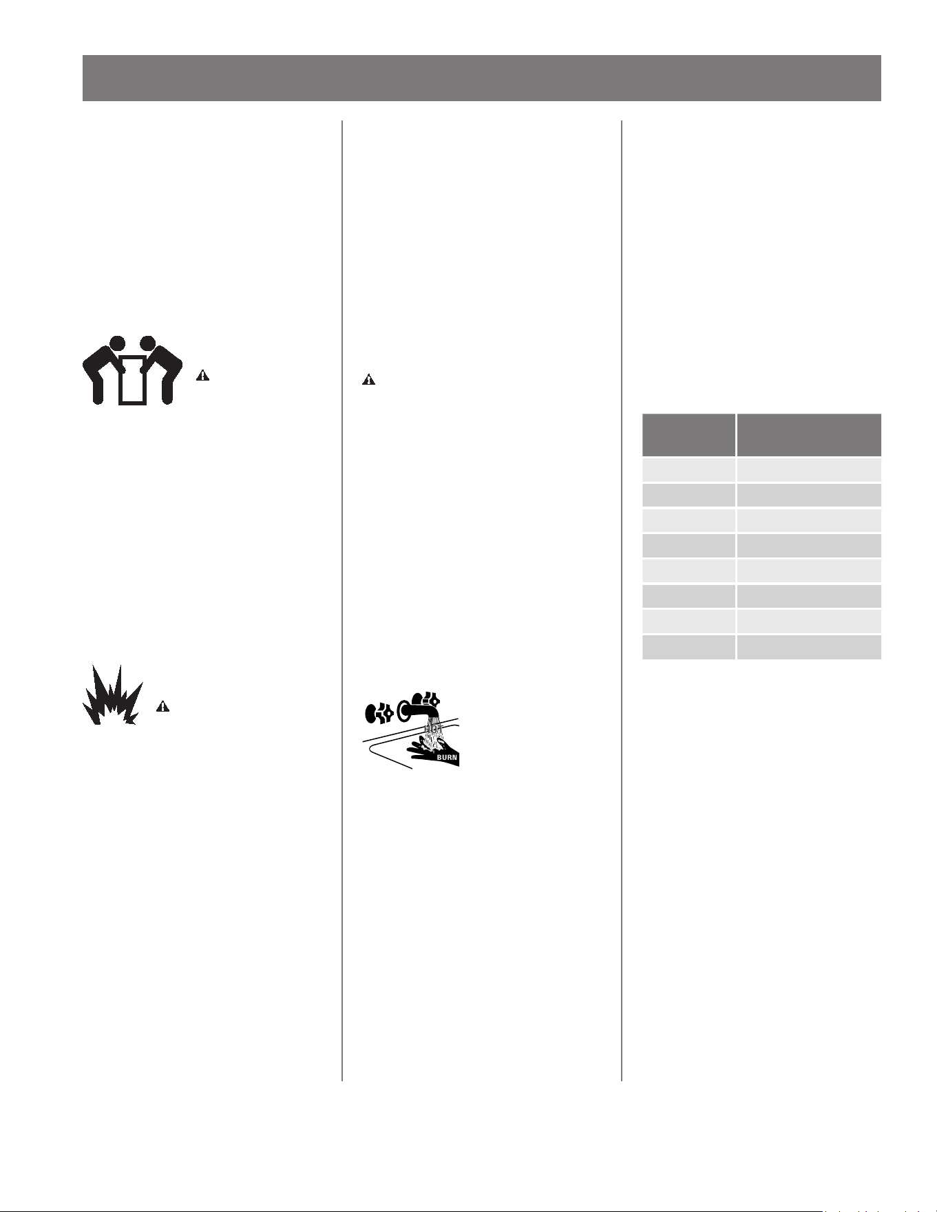
Table 5: Scalding Table
Temperature
Time to Produce a
Serious Burn
120°F (49°C) More than 5 minutes
125°F (52°C) 1½ to 2 minutes
130°F (54°C) About 30 seconds
135°F (57°C) About 10 seconds
140°F (60°C) Less than 5 seconds
145°F (63°C) Less than 3 seconds
150°F (66°C) About 1½ seconds
155°F (68°C) About 1 second
For more informaon about changing
the factory temperature seng, refer
to the “Temperature Sengs” secon
in this manual on page 49.
• Water temperature will be hoer if
someone adjusted the set tempera-
ture to a higher seng.
• Should overheang occur or the
burner fail to shut o, turn o the
manual gas supply valve to the
water heater and call a qualied
person.
IMPORTANT SAFETY INFORMATION
Residenal Non-Condensing Gas Tankless Water Heater Use and Care Guide • 15
IMPORTANT SAFETY INFORMATION
To reduce the risk of unusually hot
water reaching the xtures in the
house, install Thermostac Mixing
Valves at each point-of-use.
If anyone in your home is at parcular
risk of scalding (for example, the
elderly, children, or people with
disabilies) or if there is a local code
or state law requiring a certain water
temperature at the hot water tap,
these precauons are parcularly
important.
According to a naonal standard
American Society of Sanitary
Engineering (ASSE 1070) and most
local plumbing codes, the water
heater’s thermostat should not be
used as the sole means to regulate
water temperature and avoid scalds.
Water Contaminaon Risk
Do not use chemicals that could
contaminate the potable water supply.
Do not use piping that has been
treated with chromates, boiler seal, or
other chemicals. Suitable for potable
water heang only.
Fire Risk
To reduce the risk of a
re that could result in
property damage, or serious injury or
death:
• Do not store things that can burn
easily such as paper or clothes next
to the water heater.
• Do not store or use gasoline or other
ammable substances in the vicinity
of this or any other appliance.
• Do not use this appliance if any part
has been in contact with or been im-
mersed in water. Immediately call a
qualied installer or service agency
to replace a ooded water heater.
Do not aempt to repair the unit. It
must be replaced.
Explosion Risk
High pressures in the
water heater can cause
an explosion resulng in property
damage, serious injury or death. A
Pressure Relief Valve is required to
be installed on the water heater.
A Pressure Relief Valve is supplied
with X3® models and shall be eld
supplied for B models. Addional
pressure protecve equipment may
be required by local codes.
A naonally recognized tesng
laboratory maintains public inspecon
of the valve producon process
and ceres that it meets the
requirements for Relief Valves for Hot
Water Supply Systems, ANSI Z21.22.
The Pressure Relief Valve’s relief
pressure must not exceed the working
pressure rang of the water heater as
stated on the rang plate.
Carbon Monoxide Risk
WARNING! This
water heater
operates by burning
gas. Carbon
monoxide is a
colorless, odorless,
gas that is a by-product of burning of
fuels such as coal, wood, charcoal,
oil, kerosene, propane, and natural
gas. Breathing excessive and
abnormal amounts of carbon
monoxide can cause carbon
monoxide poisoning, resulng in
serious injury or death. This water
heater must be supplied with
adequate combuson air and must
be properly vented to the outdoors.
Have a qualied person (licensed
plumber, authorized gas company
personnel, or authorized service
technician) install the venng system
using these installaon instrucons.
Install a fuel gas and carbon
monoxide detector in the living areas
of your home.
Failure to follow these instrucons
can result in serious injury or death
from carbon monoxide poisoning.
16 • Residenal Non-Condensing Gas Tankless Water Heater Use and Care Guide
Read Before
Installaon
1
Review all of the instrucons
before you begin work.
Improper installaon can
damage the water heater, your home
and other property, and can present
risks of serious injury or death.
2
The Indoor water heater is
designed for a concentric
venng system which uses a
one pipe system with two ducts for
combuson air and exhaust air. The
outdoor water heater is designed for
outdoor installaon only. This water
heater must be installed:
• Following all local codes, or in the
absence of local codes, follow the
current edion of ANSI Z223.1/NFPA
54, Naonal Fuel Gas Code.
• For installaon in manufactured
homes (mobile homes) follow the
current edion of The Manufactured
Home Construcon and Safety Stan-
dard, Title 24 CFR, Part 3280 and/or
CSA Z240 MH Series, Manufactured
Homes.
• Follow the electrical code require-
ments of the local authority having
jurisdicon. In the absence of such
requirements, follow the current
edion of the Naonal Electrical
Code ANSI/NFPA 70.
This is available from the following:
CSA Group, Inc.
United States:
8501 East Pleasant Valley Road
Cleveland, OH 44131
Naonal Fire Protecon Associaon
1 Baerymarch Park
Quincy, MA 02269
Check with local code ocials about
codes governing this installaon.
Have your installaon inspected by a
code ocial to ensure the installaon
meets all local codes.
NOTICE: Installaon and service must
be performed by a qualied installer
(for example, a licensed plumber or
gas er). Otherwise, the warranty
will not apply. The installer (licensed
professional) is responsible for the
correct installaon of the water
heater and for compliance with all
naonal, state and local codes.
Massachuses code requires this
water heater to be installed in
accordance with Massachuses
248-CMR 2.00 and 248-CMR 5.00:
State Plumbing Code. Other local
and state authories may have
similar requirements or other codes
applicable to the installaon of this
water heater.
3
Before you start, be sure to
check the following:
WARNING! Do not store or use
ammable materials, vapors, or
liquids in the same locaon where
this water heater is installed.
• All gas water heaters require correct
installaon to ensure safe and e-
cient operaon. This manual must
be followed exactly. Read the enre
manual before installaon and re-
view the "Important Safety Informa-
on" secon (see page 13).
• Carefully plan the installaon loca-
on of the heater and vent termina-
ons.
• The water heater must be installed
where the proper amount of com-
buson air will be available to it at
all mes without obstrucons. The
water heater must be direct vented.
• The length of piping between the
water heater and xture determines
the me it takes for the hot water
to arrive. Consider installing the
water heater closer to xtures if
the plumbing system allows for it.
The water heater should be the rst
appliance to access the water line
aer the ulity water meter.
• Locate your water heater close to a
drain where water leakage will not
do damage to surrounding areas. As
with any water heang appliance,
the potenal for leakage at some
me in the life of the product does
exist. A drain pan, or other means of
protecon against water damage, is
recommended to be installed under
the water heater in case of leaks
to lessen the chance of sustaining
property damage. In addion, you
may install an acve water leak
detector with a shuto valve which
can turn o the water supply in the
event of a leak. The manufacturer is
not responsible for damage due to
water leaks.
• The water heater shall be securely
wall-mounted or mounted on a
stand.
• Maintain proper space for servic-
ing. Install the unit so that it can be
connected or removed easily. Refer
to the "Unit Clearances" secon for
proper clearances (see page 22).
NOTICE: For outdoor installaons,
locate the water heater in an open,
unroofed area. Maintain 3 inches
minimum clearance from the le and
right sides of the unit.
• The manufacturer does not recom-
mend installing the water heater
in an ac due to safety issues. See
the installaon secon for further
informaon.
WARNING! Failure to observe
these warnings could result in severe
personal injury, death, and/or
property damage.
GETTING STARTED
Residenal Non-Condensing Gas Tankless Water Heater Use and Care Guide • 17
GETTING STARTED
Venng/Combuson
• DO NOT install the water heater
where water, debris or ammable
vapors may get into the ue termi-
nal. This may cause damage to the
water heater and the warranty will
not apply.
• DO NOT locate your heater in a pit
or locaon where gas and water can
accumulate.
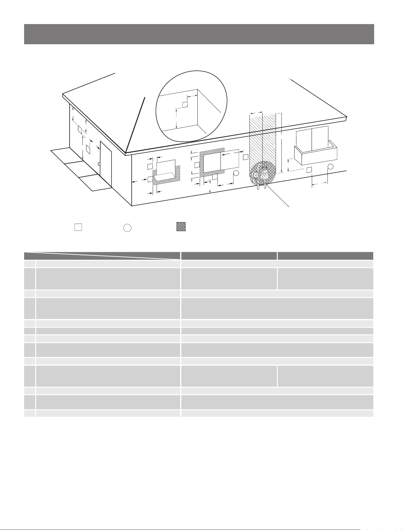
• DO NOT install the exhaust vent
within 3 feet of an overhang. Vent
terminaon must be at least 2
away from an inside or outside cor-
ner for direct vent and other than
direct vent installaons (see Figure
1 & Figure 2 for indoor and outdoor
models, respecvely).
• DO NOT install the unit where the
exhaust vent is poinng into any
opening in a building or where the
noise may disturb your neighbors.
Make sure the vent terminaon
meets the required clearance from
any doorway or opening to prevent
exhaust from entering a building.
Check local code requirements prior
to installaon (see Figure 3 & Figure
4 for indoor and outdoor models,
respecvely).
• DO NOT install next to a dryer or
any source of airborne debris that
can be trapped inside the combus-
on chamber unless the system is
direct vented. When direct vented,
do not install the air intake near the
dryer vent or any source of airborne
debris.
• DO NOT common vent the indoor
water heater with any other water
heaters or appliances.
Outdoor Applicaons
(Outdoor Model Only)
The Outdoor models are only to be
installed outdoors and only in an area
with mild, temperate climates. The
Outdoor model shall be wall mounted,
on a stand, or installed in an approved
recess box. Locate the Outdoor
model in an open, unroofed area and
maintain the minimum clearances
from the water heater exhaust
terminal (see Figure 2 & Figure 4).
NOTICE: The water piping external
to the water heater is not protected
by the Freeze Protecon system. If
installed in an area subject to freezing
temperatures, it is suggested that pipe
insulaon be installed on the external
water piping.
Inside
corner
Outside
corner
3
min.
2
min.
2
min.
Figure 1 - Overhang and Inside Corner Restricons
(Indoor Direct Venng)
Inside
corner
Outside
corner
3
min.
2
min.
2
min.
Figure 2 - Overhang and Inside Corner Restricons
(Outdoor Other than Direct Venng)
Venng/Combuson (Indoor Model)
1 min.
1 above grade and
above ancipated snow level
1 min.1 min.
Ancipated snow level
Figure 3 - Minimum Vent Clearance (Indoor Direct Venng)
Venng/Combuson (Outdoor Model)
4 min. 4 min.
4 min.
Figure 4 - Minimum Vent Clearance (Outdoor Other than Direct Venng)
18 • Residenal Non-Condensing Gas Tankless Water Heater Use and Care Guide
GETTING STARTED

Recommended Tools
and Materials
Before you start, be sure you have the
following tools and supplies:
• Plumbing tools and supplies appro-
priate for the type of water pipes in
your home.
• Thread sealant tape or pipe joint
compound approved for potable
water.
• Pipe dope approved for gas connec-
ons or gas type.
• For homes with water lines using
threaded connectors suitable for the
specic type of plasc pipe used:
CPVC or PEX (cross-linked polyeth-
ylene). Do not use PVC pipe.
• Non-corrosive gas leak detecon
soluon made from hand dishwash-
ing soap mixed with water (1 part
soap to 15 parts water) or children's
soap bubbles and a small, so-bris-
tled brush or approved gas leak
detecon device.
• An appliance dolly or hand truck to
move the water heater.
Recommended
Accessories
• Automac water leak detecon and
shut-o device
• Thermostac Mixing Valves at each
point-of-use
• Fuel gas and carbon monoxide
detector
Residenal Non-Condensing Gas Tankless Water Heater Use and Care Guide • 19
GETTING STARTED
20 • Residenal Non-Condensing Gas Tankless Water Heater Use and Care Guide
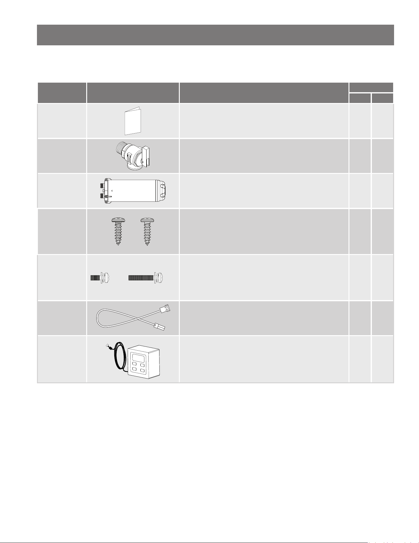
Included Items
Table 6: Items Included with your Water Heater
Item Product Image Descripon
Conguraon
X3 B
Manual
Installaon Instrucons and Use & Care Guide for
TI Indoor & TO Outdoor series model water heaters.
√ √
Pressure Relief
Valve
Pressure Relief Valve rated up to 150 psi and the maximum
BTU/hr of the water heater.
(Included with X3® models; Field supplied for B models)
√
X3® Cartridge
Prevents scale buildup and eliminates the need for annual
descaling maintenance.
√
Screws for
Vent Collar
Screws to secure the vent piping to the vent collar.
See instrucons provided with venlaon kit.
• 3/16 in x 1/2 in Vent Screw (2x)
√ √
Cartridge
Screws
(x1)
(x2)
Screws to secure the X3® Cartridge:
• M4-12 mm (1x)
• M4-25 mm (2x)
(Not applicable to B models)
√
Cascading
Cable
Cascading Cable for electronically connecng tankless
water heaters in series for greater output:
• P/N 100371915
√ √
Remote
Controller
(TO Only)
Remote Controller with 10 . cable.
Provided with TO Outdoor series model water heaters only.
NOTICE: Only 1x remote controller can be used with this
water heater.
√ √
GETTING STARTED
Residenal Non-Condensing Gas Tankless Water Heater Use and Care Guide • 21
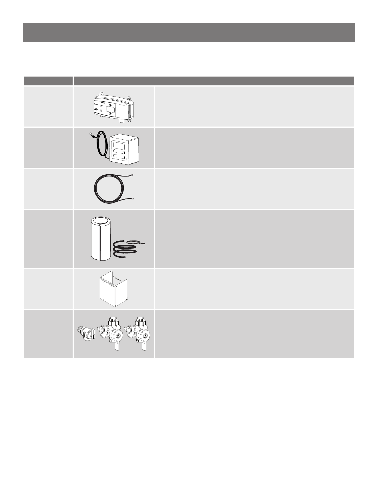
GETTING STARTED
Available Accessories
Table 7: Accessories Available for your Water Heater
Item Descripon
Wi-Fi Module
Wi-Fi Module for electronically connecng tankless water heaters to the
internet and adapter to connect to the water heater:
• P/N 100371922
Remote
Controller
Remote Controller with 10 . cable:
• P/N 100383909
NOTICE: Only 1x remote controller can be used with this water heater.
Communicaon
Cables
Communicaon Cable Extensions for Remote Controller, Wi-Fi Module, or
On-Demand Receiver:
• P/N 100377341 for 10 . (3 m)
• P/N 100377342 for 32 . (10 m)
Cartridge Freeze
Protecon
Cartridge Freeze Protecon can add an extra layer of freeze protecon to
external cartridge:
• P/N 100325654 for X3® models
Pipe Cover
Pipe Cover protects plumbing connecons to the heater while improving
the appearance of the installaon. Axes to boom of heater:
• P/N 100387711
Isolaon Valve
Kit with Pressure
Relief Valve
Isolaon Valve supports roune maintenance and allows for draining
and ushing the heater; whereas, the Pressure Relief Valve, as the name
implies, serves to limit internal pressure in the system:
• P/N 100112156
22 • Residenal Non-Condensing Gas Tankless Water Heater Use and Care Guide
Installaon
Environment
Proper Mounng and
Clearance
The water heater shall be securely
mounted on a wall that can support
the weight of the water heater.
Adjustable mounng brackets are
provided on the water heater cabinet
to securely mount the water heater to
the appropriate wall construcon. The
water line, gas line, vent condensate
drain line (if installed), and pressure
relief valve discharge line shall be
supported using eld supplied pipe
hangers. The water heater shall
not bear the weight of these lines.
The water heater requires proper
installaon clearance for operaon
and service as described in "Unit
Clearances" on the right.
WARNING! The installer (licensed
professional) is responsible for the
correct installaon of the water
heater and for compliance with all
naonal, state and local codes.
Atmosphere Temperature
(Indoor Model)
Install the indoor water heater in a
heated area where below freezing
temperatures cannot occur. The
warranty will not be covered if the
water heater is damaged due to
freezing. See "Freeze Protecon
System" on page 52
Atmosphere Temperature
(Outdoor Model)
The outdoor models are only to be
installed outdoors and only in an area
with mild, temperate climates. The
outdoor model shall be wall mounted
or on a stand. Locate the Outdoor
model in an open, unroofed area and
maintain the minimum clearances
(see the "Venng/Combuson"
secon on page 17 and Figure 6 on
the right).
NOTICE: The water piping external
to the water heater is not protected
by the Freeze Protecon system. If
installed in an area subject to freezing
temperatures, it is suggested that pipe
insulaon be installed on the external
water piping.
Combuson Air Supply
(Indoor Model)
The water heater requires fresh
combuson air and should be free of
corrosive elements and ammable
vapors. The indoor water heater
MUST be direct vented for all
installaons.
Proper Venlaon
For proper operaon the water heater
must be vented in accordance with
the secon "Venng" of the current
edion of the ANSI Z223.1/NFPA 54,
Naonal Fuel Gas Code, as well as
applicable local building codes.
Vent Drain Line
The condensate produced is acidic.
Drain the condensate in accordance
with all local codes and common
safety pracces.
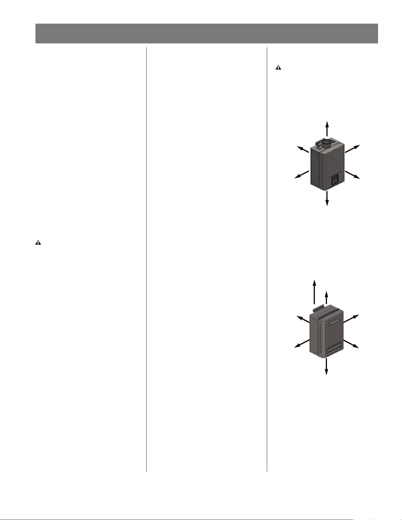
Unit Clearances
WARNING! Maintain all clearances
around the water heater. Failure
to do so could create a re hazard,
potenally leading to death, serious
injury, and/or property damage.
TOP
12 inches
BACK
0.5 inches
SIDE
3 inches
FRONT
4 inches
BOTTOM
18 inches
SIDE
3 inches
Figure 5 - Indoor Clearances
NOTICE: It is recommended for Indoor
models that the front should have 24
inches of clearance for maintenance.
TOP
12 inches
BACK
0.5 inches
SIDE
3 inches
FRONT
24 inches
BOTTOM
18 inches
SIDE
3 inches
SOFFIT / OVERHANG
36 inches
Figure 6 - Outdoor Clearances
NOTICE: Outdoor water heaters must
be at least 36 inches away from a
venlated or unvenlated sot or
eave vent; or to a deck or porch.
INSTALLATION
Residenal Non-Condensing Gas Tankless Water Heater Use and Care Guide • 23
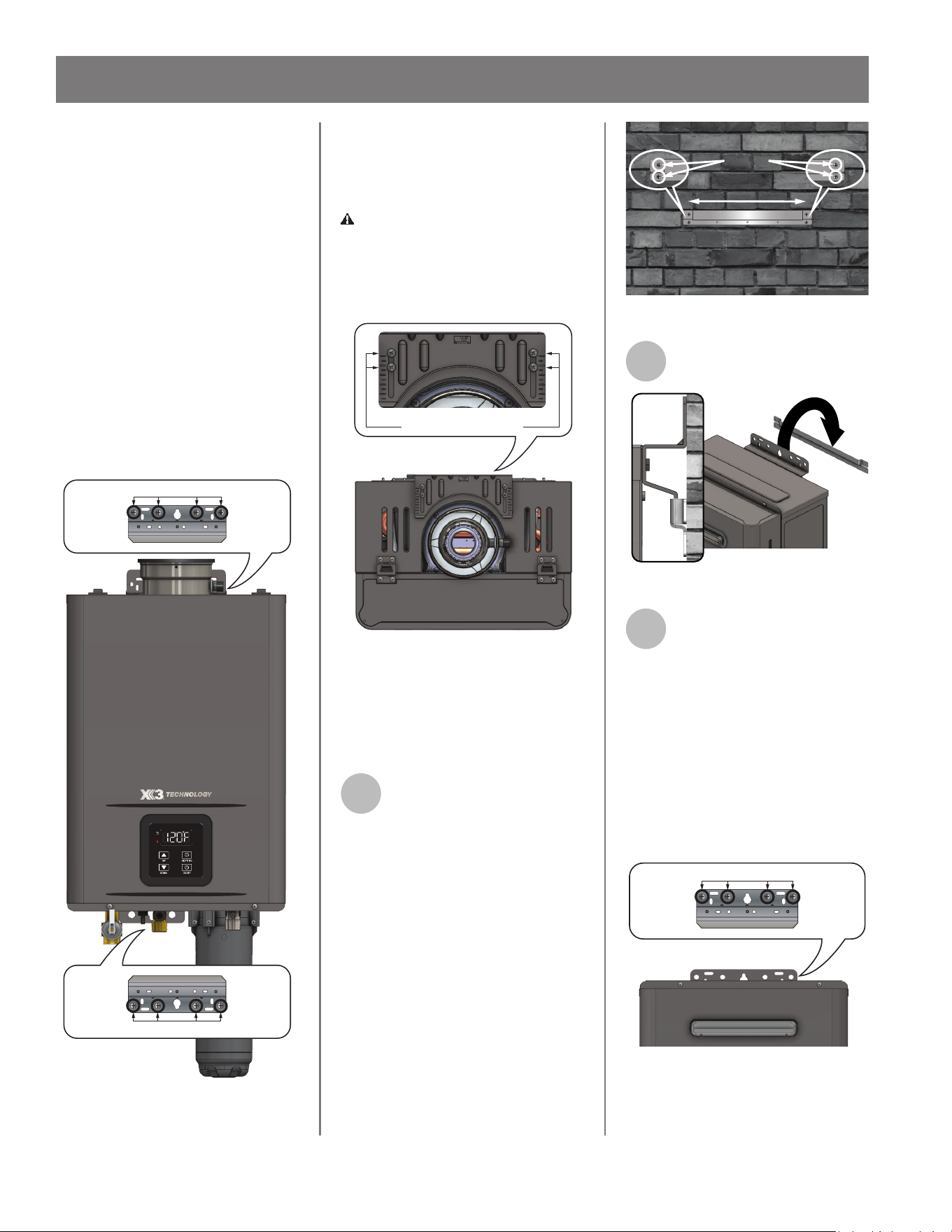
INSTALLATION
Mounng the Water
Heater (Indoor Model)
Secure the water heater rmly,
fastening appropriate screws for
wall construcon into the upper and
boom brackets of the water heater
and wall. Make sure top and boom
water heater brackets are level.
DO NOT secure to drywall only. See
Figure 7.
NOTICE: These screws are not
provided with the water heater.
Use fasteners approved for
the appropriate wall material/
construcon. Make sure to level the
bracket.
Secure with screws
Secure with screws
Figure 7 - Use Mounng Screws to Secure Water
Heater to Wall Construcon
IMPORTANT: The brackets are
extendable up to 1.16" and MUST be
secured with the two screws provided
on each side. See Figure 8.
WARNING! Failure to properly
secure extendable mounng brackets
could create a gas and re hazard,
potenally leading to death, serious
injury, and/or property damage.
Secure with screws
Figure 8 - Verify Bracket is Secured with Screws
Mounng the Water
Heater (Outdoor
Model)
1
Secure the wall mounng
bracket to an exterior wall. As
an example, Figure 9 shows
the wall mounng bracket installed to
masonry.
NOTICE: The supplied fasteners are
lag bolts for wood studs only. When
mounng on any other surface, use
fasteners approved for that wall
material/construcon. Make sure to
level the bracket.
16” (406.4 mm) Center
Exterior Masonry Shown:
Level Wall Mounting Bracket
Before Supporting Water Heater
Screws
Figure 9 - Wall Bracket Installaon
2
Hang the heater on the
mounng bracket (Figure 10).
Figure 10 - Hang Water Heater on Wall Bracket
3
Secure the water heater
rmly, fastening the
appropriate screws for wall
construcon into the upper and
boom brackets of the water heater
and wall. See Figure 11.
NOTICE: These screws are not
provided with the water heater.
Use fasteners approved for
the appropriate wall material/
construcon. Make sure to level the
bracket.
Secure with screws.
Figure 11 - Use Mounng Screws to Secure
Water Heater to Wall Construcon

24 • Residenal Non-Condensing Gas Tankless Water Heater Use and Care Guide
INSTALLATION
Venng (Indoor Model)
WARNING! Carbon Monoxide
Hazard. This water heater must
be supplied with adequate air and
vented to outdoors. The vent system
must be installed by a qualied
person. Examples of a qualied
person include gas technicians,
authorized gas company personnel,
and authorized service technicians.
Failure to properly vent the water
heater can result in severe injury
or death from carbon monoxide
poisoning.
The water heater must be vented in
accordance with the current edion
of ANSI Z223.1/NFPA 54, Naonal Fuel
Gas Code, as well as applicable local
building codes.
The water heater is designed for a
concentric venng system, which uses
a one pipe system with two ducts for
combuson air and exhaust air.
The manufacturer approves the use
of several venng systems on new
installaons. This system is furnished
through the heater manufacturer or
distributors. See Table 8 on page 26
for approved vent terminaons and
systems.
If exisng venng and vent
terminaons are used, see "Replacing
a Water Heater Using the Exisng
Vent System" on page 25.
Venng may not intermingle with
other manufacturer's venng or
material type, other than approved
appliance adapters.
Approved Appliance Adapters:
The water heater's ue collar will
accept CoxCentric®, Centrotherm
Eco Systems Direct Vent APNC35 and
Ubbink venng without the need
for an appliance adapter. Metal-Fab
Corr/Guard® venng will require
an approved appliance adapter to
be inserted into the water heater's
ue collar. See Table 8 for approved
appliance adapters.
General Rules for Venng
Water Heaters:
• Follow the vent pipe's manufactur-
er's instrucons when installing the
vent pipe.
• Place the water heater as close as
possible to the vent terminaon.
• DO NOT weld, glue or permanently
bond the vent pipe to the water
heater's vent collar.
• DO NOT cut or alter the vent collar
of the unit.
• The vent must be easily removable
from the top of the water heater for
normal service and inspecon of the
unit and vent system.
• The venng is approved for zero
(0") clearance to combusbles and
non-combusbles.
• Avoid using an oversized vent pipe
or using extremely long runs of the
pipe.
• DO NOT common vent or connect
any vent from other appliances to
the water heater vent.
• The water heater shall not be
connected to a chimney ue serving
a separate appliance, designed to
burn solid fuel.
General Rules for Vent
Terminaons:
• Avoid locang the water heater
vent terminaon near any air intake
devices. These fans can pick up
the exhaust ue products from the
water heater and return them to the
building. This can create a health
hazard.
• Locate the vent terminaon so that
it cannot be blocked by any debris,
at any me. Most codes require
that the terminaon be at least 12
inches above grade and ancipated
snow level, but the installer may
determine if it should be higher
depending on the job site condion
and applicable codes.
• To reduce the risk of carbon mon-
oxide poisoning, install a fuel gas
and carbon monoxide detector.
Install and maintain the detector in
accordance with the manufacturer's
instrucons and local codes.
Installing Sidewall Terminaon
& Blocker Plate (Metal-Fab
Corr/Guard®):
Orient the sidewall terminaon so
the air intake openings are facing
downward (see Kit Instrucons
provided with sidewall terminaon).
The blocker plate provided with the
Metal-Fab Corr/Guard® sidewall
terminaon kit must be installed to
ensure proper operaon of the water
heater. Failure to install the blocker
plate to the venng system could in
rare cases force exhaust gases into
the combuson air supply, resulng
in noisy or otherwise improper
operaon of the water heater.
General Rules for
Condensaon Traps:
• The vent should slope towards
the heater and the vent collar. A
condensate trap must be installed
below the condensate collector's
drain nipple.
• For eld made traps using tubing,
make sure the trap loop has su-
cient water to prevent exhaust gases
from entering the installaon space
before operang the water heater.
DO NOT operate the water heater
if the trap does not have sucient
water. Inspect the drain line yearly
for any damage and for sucient
water in the trap loop.
• This venng component must be
installed in roof top terminaons
and when horizontal terminaons
exceed 8 . of equivalent vent
length, excluding the sidewall termi-
naon. Condensate is corrosive and
should be treated and disposed of
according to local codes. See Figure
12 & Figure 13.
Replacing a Water
Heater Using the
Exisng Vent System
WARNING! Improper venng of
this appliance can result in excessive
levels of carbon monoxide which
can result in severe personal injury
or death. Improper installaon
can cause nausea or asphyxiaon,
severe injury or death from carbon
monoxide and ue gases poisoning.
The product warranty will not apply
to improper installaons.
WARNING! When installing the
vent system, all applicable naonal
and local codes must be followed.
If you install thimbles, re stops
or other protecve devices and
they penetrate any combusble or
noncombusble construcon, be
sure to follow all applicable naonal
and local codes.
DO NOT use Category I or Category II
venng system with this water heater.
If exisng venng and vent
terminaons are used, they MUST be
cleared of ALL restricons, such as a
restrictor plate, for proper operaon.
Read the enre "Venng" secon
of this manual and make sure your
vent system is properly installed.
Inspect the exisng vent system for
obstrucons, corrosion, and proper
installaon. Repair or replace if
necessary.
Vent Length and
Number of Elbows
Allowed
• For best results, a vent system
should be as short and straight as
possible.
• This water heater must be vented
with approved concentric venng as
described in Table 8 on the follow-
ing page.
• Follow the vent pipe manufacturer's
instrucons and the instrucons in
this manual when installing the vent
pipe.
• DO NOT common vent this appli-
ance with any other vented appli-
ance.
• DO NOT terminate vent inside
a chimney. If the vent must go
through the chimney, it must run
through the top of the chimney and
terminate with the roof terminaon
listed in Table 8. Install per the vent
manufacturer's instrucons.
• When the horizontal vent run
exceeds 5 ., support the vent run
at 3 . intervals with overhead
hangers.
• The maximum length of exhaust
vent pipe must not exceed 45 ., de-
ducng 5 . for each 90° elbow used
in the venng system. See Table 9 &
Table 10
• DO NOT use more than 4 pieces of
90° elbows.
NOTICE: If an 90° elbow connects to
the vent collar directly, the connecon
is equivalent to 5 . of vent length.
Be sure to calculate total vent length
including the connecon part as 5 .
when using this connecon.
Residenal Non-Condensing Gas Tankless Water Heater Use and Care Guide • 25
INSTALLATION
26 • Residenal Non-Condensing Gas Tankless Water Heater Use and Care Guide
INSTALLATION
Table 8: Acceptable Concentric Venng
Vent Brand Descripon & Model Number Part Number
CoxCentric®
Sidewall Terminaon Kit (13-3/4" Terminaon, 87° Elbow) 100399307
Sidewall Terminaon Kit (28-3/4" Terminaon, 87° Elbow) 100399308
Roof Terminaon Kit 100399342
Metal-Fab
Corr/Guard®
Sidewall Terminaon Kit, 3CGVPHK-AO (does not include straight pipe) 100383605
Roof Terminaon Kit, 3CGVPVK-AO (does not include straight pipe) 100383608
Appliance Adapter - Vercal Applicaons, 3CGRLSV 100383626
Centrotherm
Eco Systems
Direct Vent
APNC35
11-1/2" Concentric, Sidewall Terminaon Kit 100266115
21" Concentric, Sidewall Terminaon Kit 100266117
38" Roof Terminaon Kit 100266118
18" Roof Terminaon Kit 100305170
Ubbink 21" Non-Condensing Horizontal Terminaon Diverter Kit 223187
Table 9: Acceptable Vent Length
Vent Type Diameter Maximum Number of 90° Elbows Maximum Vercal & Horizontal (Total) Vent Length
Concentric 3 inch / 5 inch 4* 45 .
*For each 90° elbow added, deduct 5 feet from maximum vent length. Two 45° elbows are equivalent to one 90° elbow.
Table 10: Maximum Vent Length with Elbows
Number of 90° Elbows Maximum Vercal & Horizontal Vent Length*
0 45 .
1 40 .
2 35 .
3 30 .
4 25 .
*NOTICE: Table 10 excludes concentric terminaon.
Residenal Non-Condensing Gas Tankless Water Heater Use and Care Guide • 27
INSTALLATION
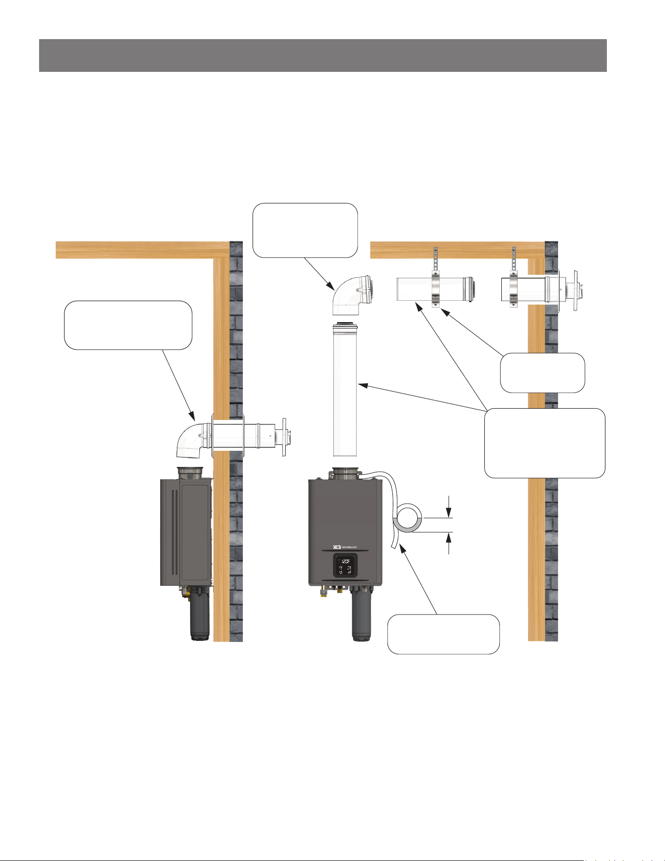
Venng Illustraons
For details of the venng installaon, refer to the CoxCentric®, Metal-Fab Corr/Guard® or Centrotherm Eco Systems Direct Vent
APNC35 concentric venng installaon manuals. See Figure 12 and Figure 13 for proper venng conguraons for horizontal and
vercal applicaons.
*Condensate must be disposed of according to local code.
*Verify there is sufficient water in the trap loop to create barrier.
Horizontal Installaon (CoxCentric® Shown)
Straight Sidewall Kit
13-3/4": 100399307
Configuraon B
Vent length greater than 8
Configuraon A
Vent length 8 (equivalent) or less
Pipe Hanger
100383625
Condensate Trap*
Straight Pipe
3" Min.
Elbow
45°: 100399344
87°: 100399343
10": 100399309
20": 100399310
40": 100399341
28-3/4": 100399308
Figure 12 - Horizontal Installaon
28 • Residenal Non-Condensing Gas Tankless Water Heater Use and Care Guide
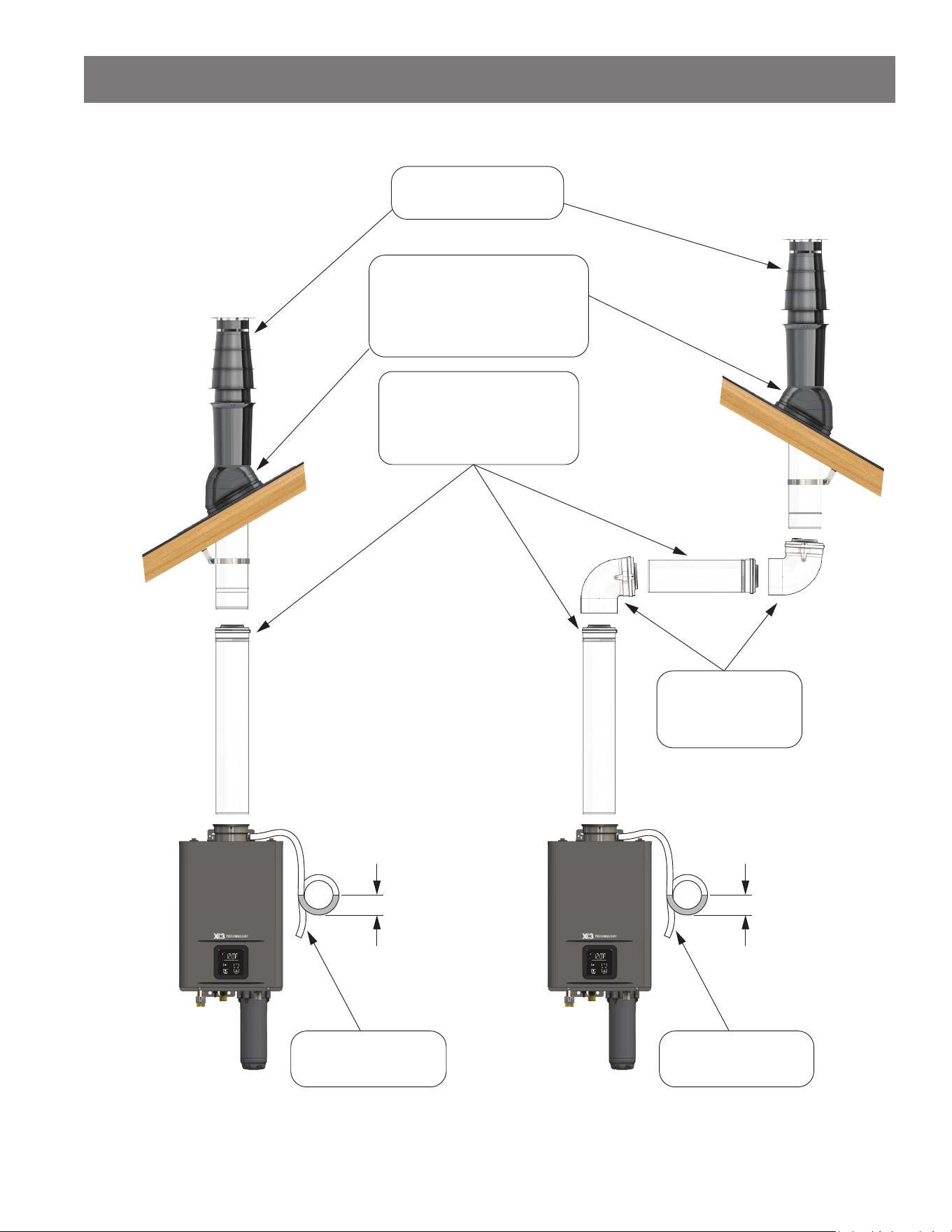
INSTALLATION
Vercal Installaon (CoxCentric® Shown)
Configuraon B
Configuraon A
Roof Terminaon Kit
100399342
Roof Flashing
1/12 to 6/12 pitch: 100399346
6/12 to 12/12 pitch: 100399347
9/12 to 17/12 pitch: 100399348
Flat: 100399345
Elbow
*Condensate must be disposed of
according to local code.
*Verify there is sufficient water in the
trap loop to create barrier.
Condensate Trap*
3" Min.
Condensate Trap*
3" Min.
45°: 100399344
87°: 100399343
Straight Pipe
10": 100399309
20": 100399310
40": 100399341
Figure 13 - Vercal Installaon
Residenal Non-Condensing Gas Tankless Water Heater Use and Care Guide • 29
INSTALLATION
Vent Terminaon Clearances
Fixed
Closed
Operable
Fixed
closed
Operable
B
V
V
V
V
V
V
V
V
C
B
B
X
A
M
K
Regulator vent outlet.
In the event no
regulator is present,
H and I can be
disregarded
.
V
Legend:
= Vent terminal
X
= Air supply inlet
= Area where terminal is not permitted
B
B
J
F
X
B
L
E
D
Inside
corner detail
V
A
G
H
15 ft
I
Table 11: Vent Terminaon Clearances
Direct Vent Other than Direct Vent
A Clearance above grade, veranda, porch, deck, or balcony 1 (30 cm)
B Clearance to window or door that may be opened 1 (30 cm)
4 (1.2 m) below or to side of
opening; 1 (30 cm) above opening
C Clearance to permanently closed window 0
D
Vercal clearance to venlated sot located above the
terminal within a horizontal distance of 2 (61 cm) from
the center line of the terminal
3 (91 cm)
E Clearance to unvenlated sot 3 (91 cm)
F Clearance to outside corner 2 (61 cm)
G Clearance to inside corner 2 (61 cm)
H
Clearance to each side of center line extended above
meter/regulator assembly
*
I Clearance to service regulator vent outlet *
J
Clearance to non-mechanical air supply inlet to a
building or the combuson air inlet to any other
appliance
1 (30 cm)
4 (1.2 m) below or to side of
opening; 1 (30 cm) above opening
K Clearance to mechanical air supply inlet 3 (91 cm) above if within 10 (3 m) horizontally
L
Clearance above paved sidewalk or paved driveway
located on public property
7 (213 cm)**
M Clearance under veranda, porch deck, or balcony 1 (30 cm)***
*Clearance in accordance with local installaon codes and the requirements of the gas supplier.
**A vent shall not terminate directly above a sidewalk or paved driveway that is located between two single family dwellings and serves both dwellings.
***Permied only if veranda, porch, deck, or balcony is fully open on a minimum of two sides beneath the oor.
Notes:
1) In accordance with the current ANSI Z223.1/NFPA 54, Naonal Fuel Gas Code.
2) If locally adopted installaon codes specify clearances dierent than those illustrated, then the most stringent clearance shall prevail.
3) Blocking air supply and exhaust vent by snow may cause incomplete combuson and an appliance failure. Install the terminaon by providing sucient
clearance from ancipated snow line in accordance with local code or manufacturer's instrucons and make sure there is no blockage.
4) Provide an appropriate clearance between a vent terminaon and a building to prevent degradaon to building materials caused by ue gases.
30 • Residenal Non-Condensing Gas Tankless Water Heater Use and Care Guide
Clearances for Sidewall
Terminaons (Indoor
Model)
WARNING! Improper installaon
can result in carbon monoxide
poisoning or death. Follow all local
and naonal codes in regard to
proper terminaon clearances.
In the absence of such codes, the
clearances below can be used as
guidelines. Local codes supersede
these guidelines.
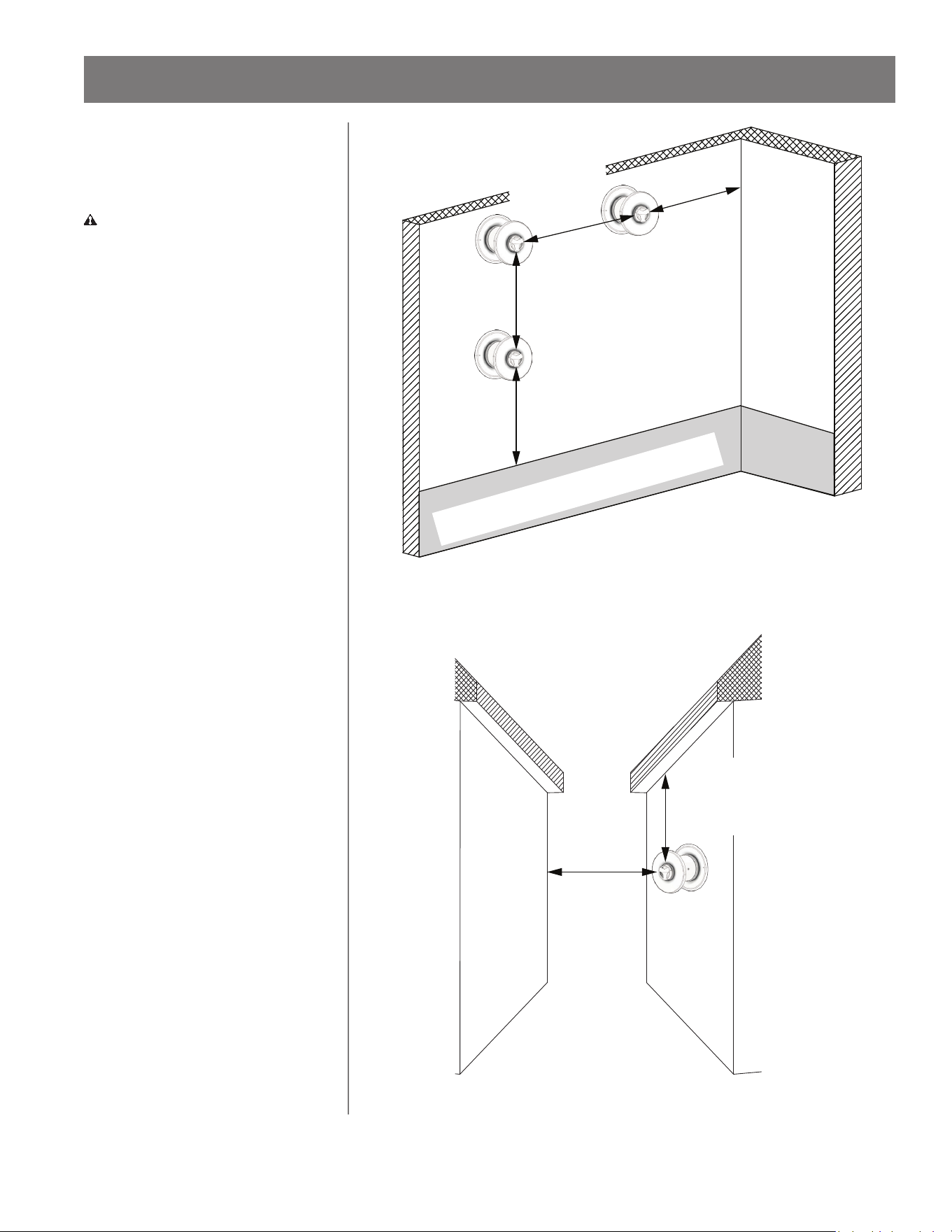
Mulple-unit concentric wall
terminaon clearances:
• Space each concentric wall termina-
ons at least 1 . away from each
other, no maer the orientaon. A
concentric wall terminaon must
also be at least 2 . away from an
inside corner. If the adjacent wall is
less than 2 . in length, the mini-
mum required distance away from
the inside corner will be equal to the
length of the adjacent wall (Figure
14).
• Concentric wall terminaons should
be at least 3 . away from a venlat-
ed or unvenlated sot. Concentric
wall terminaons should be at least
2 . away from an opposite surface
or wall (Figure 15).
• DO NOT place the terminaon
directly in front of an opening into a
building.
INSTALLATION
Inside
corner
Ancipated snow level
1
min.
2
min.
1
min.
1
min.
Figure 14 - Mul-Unit Concentric Wall Terminaons (TI Indoor Models)
2
min.
3
min.
Figure 15 - Concentric Wall Terminaon Clearances (TI Indoor Models)
Inside
corner
2 .
min.
5 .
min.
3 .
min.
2 inch min.
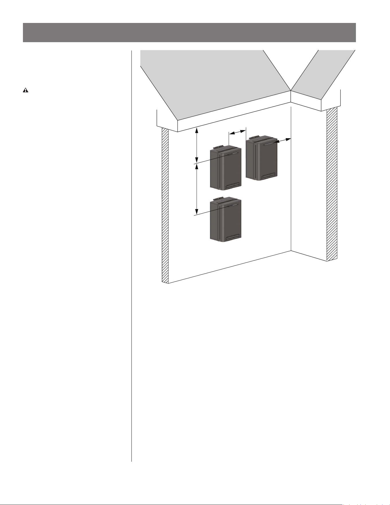
Figure 16 - Mul-Unit Outdoor Terminaons (TO Outdoor Models)
Clearances for Mul-
Unit Water Heaters
(Outdoor Model)
WARNING! Improper installaon
can result in carbon monoxide
poisoning or death. Follow all local
and naonal codes in regard to
proper terminaon clearances.
In the absence of such codes, the
clearances below can be used as
guidelines. Local codes supersede
these guidelines.
Mulple-unit outdoor water heater
terminaon clearances:
• Outdoor water heaters must have
at least 2 inches of horizontal space
between each unit. There must be
at least 5 . of space between the
exhaust terminals of each unit if the
water heaters are installed vercally.
The water heater exhaust terminal
must also be at least 2 . away from
an inside corner. (Figure 16).
• Outdoor water heaters must be at
least 3 . away from a venlated or
unvenlated sot or eave vent; or
to a deck or porch (Figure 16).
• DO NOT place the water heater
directly in front of an opening into a
building.
Residenal Non-Condensing Gas Tankless Water Heater Use and Care Guide • 31
INSTALLATION
32 • Residenal Non-Condensing Gas Tankless Water Heater Use and Care Guide
Clearances for Rooop
Terminaons
WARNING! Improper installaon
can result in carbon monoxide
poisoning or death. Follow all local
and naonal codes in regard to
proper terminaon clearances.
In the absence of such codes, the
clearances below can be used as
guidelines. Local codes supersede
these guidelines.
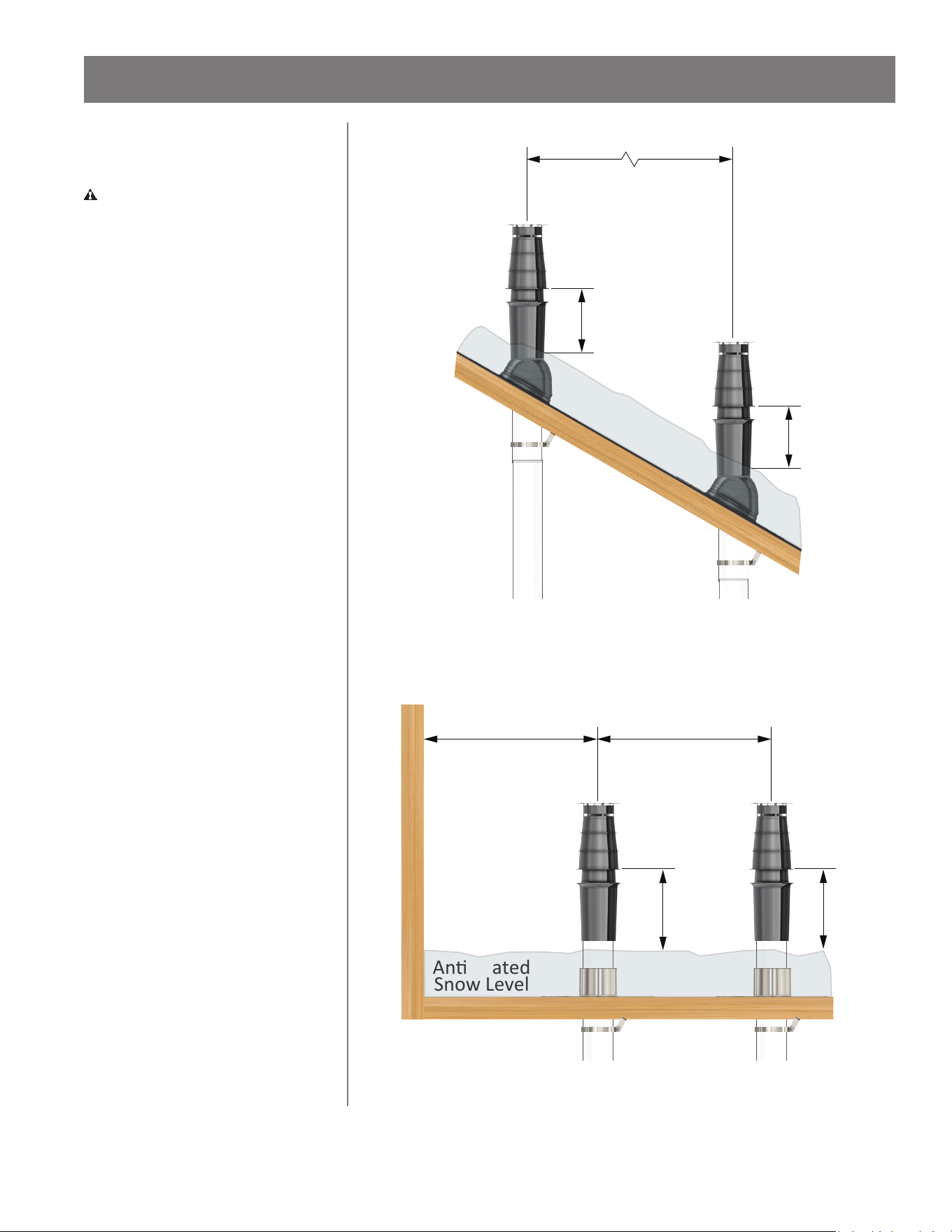
Minimum spacing between mulple
concentric terminaons for rooops:
• The air intake must be a vercal
distance of at least 1 . above the
ancipated snow level.
• On a dierent level: 5 . spacing be-
tween each terminaon (Figure 17).
• On the same level: 2 . spacing be-
tween each terminaon (Figure 18).
• The exhaust terminaon must be a
horizontal distance of at least 2 .
from a wall or surface unless speci-
ed dierently by local code (Figure
18).
INSTALLATION
Exhaust Gas
Air Intake
5 min.
1
min.
1
min.
Ancipated
Snow Level
Figure 17 - Sloped Roof Terminaon
Exhaust Gas
Air Intake
1
min.
1
min.
2 min. 2 min.
Vercal Wall
Ancipated
Snow Level
Figure 18 - Flat Roof Terminaon
Residenal Non-Condensing Gas Tankless Water Heater Use and Care Guide • 33
INSTALLATION
Gas Supply and Gas
Pipe Sizing
Gas Piping
WARNING! This water heater is
designed for Natural Gas operaon
only. Refer to the water heater’s
rang plate. Failure to follow these
instrucons can result in serious
injury or death from explosion, re or
carbon monoxide poisoning.
Ensure that any and all gas regulators
used are operang properly and
providing gas pressures within the
specied range as shown in Table 12.
Excess gas inlet pressure may cause
serious accidents.
Gas piping must be installed according
to local and state codes, or in the
absence of these codes, the current
edions of ANSI Z223.1/NFPA 54,
Naonal Fuel Gas Code.
• DO NOT aach the gas line to the
water heater unl aer the supply
line pressure tesng has been com-
pleted to avoid any damage to the
water heater.
• The minimum and maximum inlet
gas pressures are shown in Table 12:
Table 12: Minimum & Maximum Inlet
Gas Pressures
Gas Type Inlet Gas Pressure
Natural
Gas
Min. 4.0" W.C.
Max. 10.5" W.C.
Size the gas pipe appropriately to
supply the necessary volume of
gas and allowable pressure drop
required for the water heater using
the manufacturer's gas piping
instrucons, local and state codes,
or in the absence of these codes,
the current edions of ANSI Z223.1/
NFPA 54, Naonal Fuel Gas Code.
Otherwise, ow capabilies and
output temperatures will be limited.
See Table 13 on the following page.
NOTICE: If you are replacing a smaller
input water heater, you may need to
increase the gas line size.
• Inlet gas pressures that fall outside
the range of values listed above may
adversely aect the performance
of the water heater. These pres-
sures are measured when the water
heater and any other gas appliance
served by the same gas line are in
full operaon.
• Inlet gas pressure must not exceed
the maximum values in Table 12; gas
pressure above the specied range
will cause dangerous operang con-
dions and damage the unit.
• If the gas supply pressure to the
heater is greater than the specied
maximum, a eld-supplied regula-
tor is required. The regulator must
lower the gas pressure within the
approved range.
• Install the gas regulator according
to the manufacturer’s instrucons.
Some manufacturers may require a
certain amount of straight pipe on
the outlet prior to any addional
ngs.
• The regulator must be sized for the
water heater's minimum to maxi-
mum input and provide the speci-
ed pressures that are listed on the
rang plate.
• In the absence of minimum install
distance stated by the regulator
manufacturer, it is recommended
that there be at least 3 . of piping
between the regulator outlet and
the water heater's inlet gas connec-
on.
Gas Connecons
1
Use a 3/4 inch union to
connect gas piping to the
water heater's 3/4 inch male
NPT connecon.
NOTICE: Refer to Table 13 if 1/2 inch
piping is desired. If the maximum
input of the unit is greater than the
maximum delivery capacity for the
installaon's length of 1/2 inch pipe,
then 3/4 inch piping is required.
2
Install a full port manual gas
shut-o valve between the
water heater and the gas
supply line.
3
When the gas connecons
are completed, it is necessary
to perform a gas leak test
either by applying soapy water to all
gas ngs and observing for bubbles
or by using a gas leak detecon
device.
• The water heater and its individual
shut-o valve must be disconnected
from the gas supply piping system
during any pressure tesng of that
system at test pressures in excess of
1/2 psi (3.5 kPa).
• The water heater must be isolated
from the gas supply piping system
by closing its individual manual shut-
o valve during any pressure tesng
of the gas supply piping system at
test pressures equal to or less than
1/2 psi (3.5 kPa).
4
Always purge the gas line of
any debris and/or water
before connecng to the gas
inlet.
34 • Residenal Non-Condensing Gas Tankless Water Heater Use and Care Guide
Table 13: Natural Gas Supply Piping Unit: Cubic feet per hour
Pipe Size Length: (m)
Diameter:
in.
10' 20' 30' 40' 50' 60' 70' 80' 90' 100' 125' 150' 200'
1/2" 172 118 95 81 72 65 60 56 52 50 44 40 34
3/4" 360 247 199 170 151 137 126 117 110 104 92 83 71
1" 678 466 374 320 284 257 237 220 207 195 173 157 134
1-1/4" 1,309 957 768 657 583 528 486 452 424 400 355 322 275
1-1/2" 2,090 1,430 1,150 985 873 791 728 677 635 600 532 482 412
2" 4,020 2,760 2,220 1,900 1,680 1,520 1,400 1,300 1,220 1,160 1,020 928 794
Water
Heater
199,000 BTU/h
A B
C
Dryer
35,000 BTU/h
Gas Meter
Furnace
120,000 BTU/h
Range
65,000 BTU/h
5' (1.5 m) Length
1-1/4" Pipe Size
5' (1.5 m) Length
1-1/4" Pipe Size
10' (3 m) Length
1/2" Pipe Size
10' (3 m) Length
1" Pipe Size
10' (3 m) Length
3/4" Pipe Size
15' (4.6 m) Length
1" Pipe Size
10' (3 m) Length
1/2" Pipe Size
15' (4.6 m) Length
1/2" Pipe Size
Figure 19 - Pipe Sizing Diagram
INSTALLATION
Natural Gas Supply Piping
Maximum delivery capacity of cubic
feet of gas per hour of IPS pipe
carrying Natural Gas with 0.60 specic
gravity based on 0.5" W.C. pressure
drop.
Based on Energy Content of 1,000
BTU/Cubic feet, the water heater
requires:
• 180 ³/hr for the TI/TO-180 model
• 199 ³/hr for the TI/TO-199 model
Table 13 below is from ANSI Z223.1/
NFPA 54.
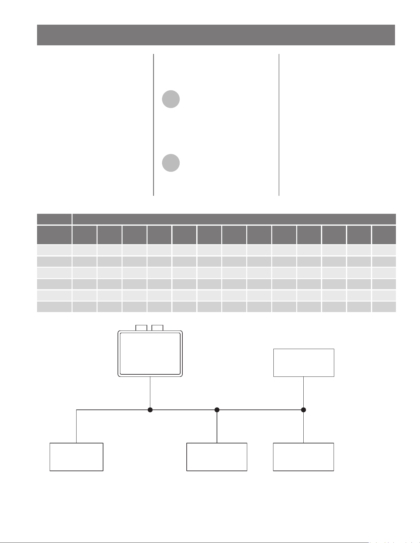
Gas Sizing Example
Based on Energy Content of 1,000
BTU/Cubic feet (Figure 19):
1
Divide each appliance's
BTU/h requirement by 1,000
BTU/³ to get the appliance's
³/h requirement. Take into account
the distance the appliance is from the
gas meter. Use Table 13 and Figure 19
below to properly size the line.
2
For secons of the gas line
supplying gas to more than
one appliance (e.g., Point A to
Point B), add up the cubic feet per
hour requirements of the appliances
that are being supplied by that
secon, and size to the farthest
appliance.
FOR EXAMPLE: The secon from
A to B supplies gas to the furnace,
range and dryer. Adding up the BTU/h
requirement and dividing by 1,000
yields a cubic per hour requirement
of 220
3
/hr of gas. The farthest
appliance is the range, which is 50
away from the meter. Looking at the
chart below, and under the column of
50 , Secon A to B needs to be 1" in
order to supply 220
3
.
Residenal Non-Condensing Gas Tankless Water Heater Use and Care Guide • 35
INSTALLATION
Water Connecons
WARNING! DO NOT use this
appliance if any part has been
under water. Immediately contact a
qualied installer or service agency
to replace a ooded water heater.
DO NOT aempt to repair the unit! It
must be replaced!
IMPORTANT: DO NOT reverse the hot
outlet and the cold inlet connecons
to the water heater. If you reverse the
connecons, the water heater will not
acvate properly.
Determine the type of water pipes in
your home. Use ngs appropriate
for the type of pipe in your home
(copper, CPVC or PEX). Do not use iron
or PVC pipe – they are not suitable
for potable water. All pipes, pipe
ngs, valves and other components,
including soldering materials, must be
suitable for potable water systems.
Also, an automac air vent or air
separator must be installed when
the water heater operates in a closed
loop system such as a recirculaon
system. Trapped air bubbles in the
water system can cause a pump to
cavitate or damage the water heater's
heat exchanger. This equipment
must be installed according to the
manufacturer's instrucons.
A manual shut-o valve must be
installed on the cold water inlet to the
water heater between the main water
supply line and the water heater. In
addion, a manual shut-o valve is
also recommended on the hot water
outlet.
If the water heater is installed
within, or subjected to, a closed loop
water system, a thermal expansion
tank or code approved device to
handle thermal expansion must be
installed. Follow the expansion device
manufacturer's instrucons for proper
installaon and operaon.
NOTICE: If the plumbing system is
subject to water hammer, then it is
recommended that water hammer
arrestors be installed.
Making Water Connecons
IMPORTANT: Before installing the
water heater, ush the water line
to remove all debris, and aer
installaon is complete, purge the air
from the line. Failure to do so may
cause damage to the heater.
NOTICE: There is a wire mesh lter
within the cold inlet to trap debris
from entering your water heater. This
will need to be cleaned periodically to
maintain opmum ow.
The water inlet and outlet threaded
connecons are brass. When
connecng the unit to piping made of
a dierent material, use of a dielectric
ng or a dielectric union conforming
to ASSE 1079 is recommended to
prevent corrosion and potenal
subsequent water leaks at or near the
connecon. Dielectric ngs may be
required by local plumbing codes.
1
Connect the hot water supply
using 3/4 inch NPT to the
ng marked "HOT." Follow
the same connecon guidelines as for
the cold water supply marked "COLD."
2
Double check to make sure
the hot and cold water pipes
are connected to the correct
hot and cold water ng on the
water heater.
3
Install insulaon (or heat
tape) on the water pipes
especially if the indoor
installaon area is subject to freezing
temperatures. Insulang the hot
water and return pipes will reduce
heat loss.
4
If water hammer is evident,
install water hammer
arrestors on the inlet side of
the water heater.
5
If needed, install (or adjust)
the home's Pressure
Reducing Valve.
6
A drain pan, or other means
of protecon against water
damage, is recommended to
be installed under the water heater in
case of leaks.
IF YOU HAVE COPPER PIPES
If your home has copper water
pipes, you can solder the water pipe
connecons or use compression
ngs which do not require
soldering. Compression ngs
are easier to install than soldering
pipe. Check with local plumbing
ocials to determine what types of
pipe materials are suitable for your
locaon. DO NOT use lead-based
solder.
NOTICE: DO NOT solder pipes while
they are aached to the water
heater. The water heater contains
non-metallic parts which could be
damaged. The proper way to connect
the water heater to copper water
pipes is as follows:
1
Solder a short length of pipe
(about a foot or so) to a
threaded adapter using only
95/5 n anmony or equivalent
solder.
2
Aach the threaded adapters
to the water heater's
connecons (using thread
sealant tape or pipe joint compound).
3
Connect the home's water
pipes by soldering, keeping
the connecons at the water
heater cool with wet rags.
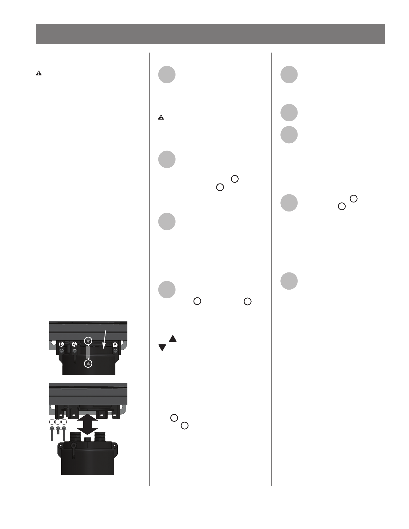
X3® Technology
WARNING! DO NOT operate water
heater unl the X3® Cartridge has
been installed into the manifold
located on the underside of the
water heater cabinet. Failure to do
so may result in leaks and potenal
property damage.
NOTICE: Base (B Model) conguraon
does not have X3®cartridge capability.
This water heater may be equipped
with X3® Scale Prevenon Technology
to inhibit scale formaon within the
heat exchanger tubing of this unit.
Part of the X3® Technology’s an-
scale protecon comes from the
special X3® Cartridge media. The X3®
Cartridge must be installed into the
manifold located on the underside of
the heater cabinet prior to operaon
of the unit (shown as follows). X3®
Scale Prevenon Technology reduces
the formaon of scale in the heat
exchanger, extending the operang
life of the unit in typical potable water
installaons. Specic water condions
may impact the eciency of X3®, such
as excessive iron (max limit 0.3 mg/l
or 0.3 ppm) or manganese (max limit
0.05 mg/l or 0.05 ppm) levels.
A BB
A
B
B
ALIGN
X3
®
CARTRIDGE
MANIFOLD
ARROWS ARE FACING BACKSIDE
Figure 20 - X3® Cartridge Installaon
X3® Cartridge Installaon
1
Remove the plug assembly
installed into the manifold
located on the underside of
the water heater cabinet. Properly
dispose of plug assembly materials.
CAUTION! Water may be present
in the manifold. Place a bucket under
the water heater cabinet to collect
any residual water.
2
Locate the three (3) screws
provided in the hardware bag
on the top of the water
heater carton. Set the one
A
screw
(M4-12mm) and two
B
screws
(M4-25mm) aside in a safe place
(Figure 20).
3
Locate the X3® Cartridge
provided with the water
heater.
NOTICE: Inspect O-rings for damage
or debris. Handle with care and verify
lubricant has been properly applied to
O-rings.
4
Insert the X3® Cartridge into
manifold and secure with the
one
A
screw and two
B
screws previously set aside in Step 2.
NOTICE: The X3® cartridge is keyed
to only install in one direcon. Align
the on the X3® cartridge with the
on the manifold (arrows will be
back facing for TI & TO series heaters).
When inserng the X3® cartridge,
push up unl the screw holes align.
Some resistance is normal. See Figure
20 for reference.
Insert and snug all three screws by
hand. Use a screwdriver to ghten the
two
B
screws rst and lastly ghten
the one
A
screw. DO NOT use a drill
or impact driver to ghten the screws.
X3® Cartridge Removal
1
Disconnect power to the
water heater by unplugging it
or by turning o the circuit at
the breaker box.
2
Close the cold inlet water
valve.
3
Open all hot water taps in the
house. When the residual
water ow has ceased, close
all hot water taps.
NOTICE: Place a bucket under the
water heater cabinet to collect any
residual water.
4
Remove the two
B
screws
and the one
A
screw
securing the X3® Cartridge to
the manifold located on the underside
of the water heater cabinet. Set the
screws aside in a safe place for
re-installaon. Note the order of the
screws when removing them.
Reference Figure 20.
5
Pull down to remove the X3®
Cartridge from the water
heater.
NOTICE: The X3® Cartridge will be full
of water. Use cauon not to lt the
cartridge unl the water has been
drained.
Outdoor Model Cartridge
Accessories
It is recommended that a Cartridge
Freeze Protecon Kit be installed if
the water heater is installed outside
or in uncondioned areas subject to
freezing temperatures.
A pipe cover is available and axes
to the boom of the water heater.
It protects plumbing connecons to
the water heater while improving the
appearance of the installaon.
For more informaon see “Available
Accessories” on page 21.
36 • Residenal Non-Condensing Gas Tankless Water Heater Use and Care Guide
INSTALLATION
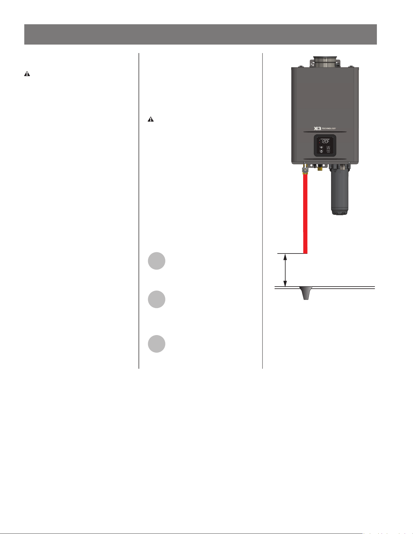
Pressure Relief Valve
WARNING! Hot water could be
released. Before operang the
pressure relief valve manually, check
that it will discharge in a safe place. If
water does not ow freely from the
end of the discharge pipe, turn the
gas supply and power OFF and call
a qualied person to determine the
cause.
Refer to the pressure relief valve
manufacturer's instrucons for
inspecon and maintenance
requirements.
The water heater has a high-
temperature shut-o switch built in
as a standard safety feature (called a
Hi-Limit switch), therefore a "pressure
only" relief valve is required.
An approved pressure relief valve is
supplied with X3® conguraons. An
approved pressure relief valve shall be
eld supplied for B conguraons.
The discharge piping for the pressure
relief valve must be directed so that
hot water cannot splash outward and
cause damage or personal injury.
Aach the discharge tube to the
pressure relief valve and run the
end of the tube to a maximum of
6 inches from the oor (Figure 21).
This discharge tube must allow free
and complete drainage without any
restricons.
If the pressure relief valve discharges
periodically, this may be due to
thermal expansion in a closed
water supply system. Contact the
water supplier or a local plumbing
professional on how to correct this
situaon.
WARNING! DO NOT plug the
pressure relief valve.
The pressure relief valve must be
manually operated periodically to
check for correct operaon. Before
operang the valve manually, check
that it will discharge in a place for
secure disposal.
NOTICE: No valve must be placed
between the pressure relief valve and
the water heater.
If another pressure relief valve is used
or needs to be replaced, it must meet
the following:
1
The pressure relief valve must
conform to ANSI Z21.22 •
CSA 4.4, and installaon must
follow local codes.
2
The discharge capacity must
be at least:
• 180,000 BTU/h for TI/TO-180 model
• 199,000 BTU/h for TI/TO-199 model
3
The pressure relief valve
needs to be rated for a
maximum of 150 psi.
Discharge Pipe
6 inches
Maximum
Figure 21 - Discharge Pipe Clearance
Residenal Non-Condensing Gas Tankless Water Heater Use and Care Guide • 37
INSTALLATION
Recirculaon
When installing a recirculaon pump,
care must be taken to properly size
the pump for the applicaon. Sizing
must be performed by the installing
contractor or engineer. Below are
the requirements that need to be
followed when sizing:
NOTICE: Running the pump
connuously will reduce the warranty
of the water heater.
• Size the recirculaon pump to ow
no less than 2 gpm and no more
than 4 gpm per heater acvaon.
The manufacturer's suggested ow
rate is 3 gpm. Refer to the water
heater's pressure drop chart on
its specicaon sheet for losses at
other ow rates. See Table 14 below
for potenal head loss.
Table 14: Head Loss
Model Flow Rate Head Loss
X3®
Models
3 gpm 27.2 .
B
Models
3 gpm 22.2 .
• The pump should be controlled
by a eld supplied aquastat with
immersion probe and an adjustable
dierenal. The minimum suggested
dierenal is 15°F.
IMPORTANT: If the inlet water
thermistor in the water heater mea-
sures the temperature of inlet water
above the temperature seng, or
above 122°F, the water heater will
shut down. In this scenario the wa-
ter heater will display code E383.
• An air eliminaon device is suggest-
ed to remove air from the piping
system. Air may cause the recircu-
laon pump to cavitate and may
reduce the water ow rate. These
items should be installed per the
manufacturer's instrucons.
The installer will need to consider the
size of water tubing, material type,
and ngs when determining the
pressure drop of the system to size
the recirculaon pump.
NOTICE: These characteriscs vary
for each tubing material of the same
nominal size. Refer to the water
tubing manufacturer for pressure
drop informaon that is needed to
size the recirculaon pump. Check
with local codes and ordinances for
addional installaon requirements.
Point-of-use thermostac mixing
valves may be used with tankless
water heaters. Consult with the
point-of-use thermostac mixing valve
manufacturer for the appropriate
valve for the applicaon. Refer to the
point-of-use thermostac mixing valve
manufacturer for proper installaon
when recirculaon is in use.
WARNING! To reduce the risk
of unusually hot water reaching
the xtures in the house, install
Thermostac Mixing Valves at each
point-of-use.
NOTICE: Figure 22 on the following
page provides the manufacturer's
suggested piping layout for
recirculaon. The suggested piping
layout is applicable to both indoor and
outdoor installaons. The installer
must properly install the system
according to the manufacturer's
instrucons and local codes. Refer
to the water heater manufacturer's
website for addional layouts.
38 • Residenal Non-Condensing Gas Tankless Water Heater Use and Care Guide
INSTALLATION
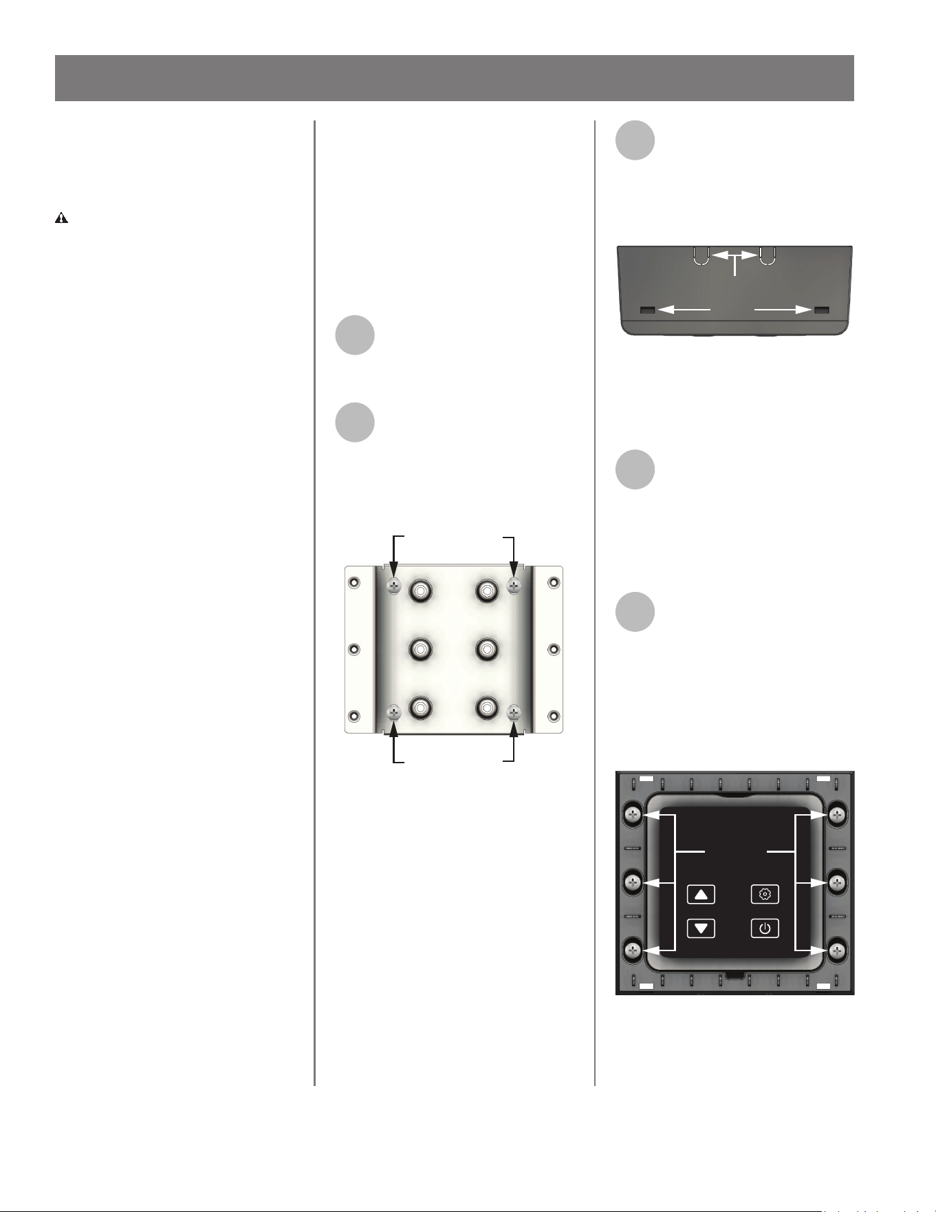
Residenal Non-Condensing Gas Tankless Water Heater Use and Care Guide • 41
Accessory Connecons
This system supports up to three
accessories connected in series.
CAUTION! Water heater
accessories are not approved for
outdoor installaon. Components
used in accessory installaon must
be installed in an indoor environment
and protected from hazardous
weather condions and freezing
temperatures.
NOTICE: If mulple water heaters
are used in a Cascade System, then
all accessories must be connected in
series to the parent unit.
Follow the accessory kit instrucons
to access the control board.
Each accessory has both a ve-pin
female connector and a secon of
cable with a ve-pin male connector
on the end. The male connector
connects to the Printed Control Board
(PCB) or to the next accessory in the
series. The ve-pin female connector
allows another accessory to connect
and create a series. When creang a
series of accessories, reference Figure
27 for indoor model water heaters
and Figure 28 for out outdoor model
water heaters.
If the length of the accessory cord
is not long enough, communicaon
cables can be purchased to extend
the length. These cables are available
in 10 . and 32 . lengths. Connect
the single ve-pin connector on the
communicaon cable to the ve-pin
female connector on the accessory.
The maximum wire length from the
water heater (the Parent unit in
a Cascade System) to the farthest
accessory is 100 feet.
IMPORTANT: A remote controller
assembly is provided with the outdoor
model water heater. Proceed to the
following secon for instrucons on
how to mount the remote controller.
Mounng the Remote
Controller
Follow the procedure below to mount
the remote controller provided with
the outdoor model water heater.
Once the remote controller has been
properly mounted, use Figure 28 to
connect the controller to the outdoor
model water heater.
1
Locate the remote controller
and metal mounng bracket
provided with the water
heater.
2
Secure the mounng bracket
to the wall using the four (4)
provided screws and wall
anchors. Reference Figure 24 for the
orientaon of the mounng bracket
when mounted.
Wall Screws
Wall Screws
Mounting Bracket
Figure 24 - Securing the mounng bracket to
the wall
NOTICE: Ensure the communicaon
cable has sucient length to reach
the desired locaon for the remote
temperature controller. Ensure
the cable is routed proper and not
exposed to any sharp edges. Also
ensure that it is mounted safely as to
not cause any trip or safety hazard.
3
Use a small athead
screwdriver to depress the
tabs holding the front cover
of the remote temperature controller.
Set the front cover aside in a safe
place for reinstallaon. See Figure 25.
Remote Controller,
Front Cover Installed
(Bottom View)
Tabs
Notches
Figure 25 - Front cover removal
4
The remote temperature
controller has two (2) cable
roung notches on the top
and two (2) on the boom. Remove
the plasc tab from the desired notch
and route the communicaon cable
through it. See Figure 25.
5
Locate the six (6) screws
provided in the kit. Secure
the remote temperature
controller to the mounng bracket
using the provided screws. Make sure
the communicaon cable is axed in
the notch before securing the remote
temperature controller to the
mounng plate. See Figure 26.
ON/OFF
DOWN
UP SETTING
Screws
Remote Controller,
Front Cover Removed
(Front View)
Figure 26 - Mounng screw locaon
INSTALLATION
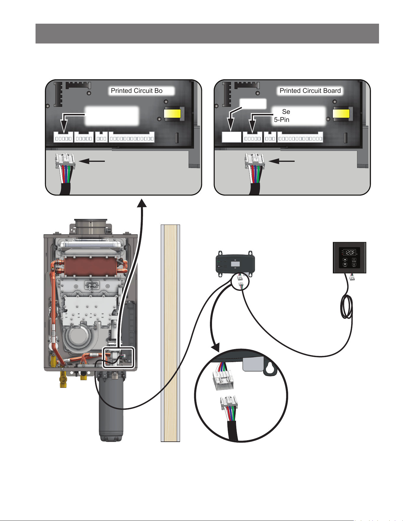
42 • Residenal Non-Condensing Gas Tankless Water Heater Use and Care Guide
INSTALLATION
Wi-Fi Module
Remote
Controller
Connecting Secondary AccessoryConnecting Primary Accessory
Indoor Wall
Indoor Wall
Accessory
5-Pin Female
Accessory
5-Pin Male
Secondary
Accessory
5-Pin Male
Printed Circuit Board
Secondary
5-Pin Connector
Primary
Primary
Accessory
5-Pin Male
Printed Circuit Board
Primary
5-Pin Connector
Accessory Connections (Indoor Model)
Figure 27 - Accessories Installed in Series (Indoor Model)
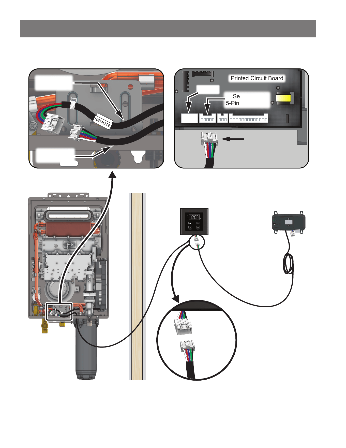
Residenal Non-Condensing Gas Tankless Water Heater Use and Care Guide • 43
INSTALLATION
Wi-Fi Module
Remote
Controller
Connecting Secondary AccessoryConnecting Remote Controller
Outdoor Wall
Indoor Wall
Accessory
5-Pin Female
Accessory
5-Pin Male
Secondary
Accessory
5-Pin Male
Printed Circuit Board
Secondary
5-Pin Connector
Remote
Accessory Connections (Outdoor Model)
To PCB
5-Pin Female
From Remote
5-Pin Male
Figure 28 - Accessories Installed in Series (Outdoor Model)
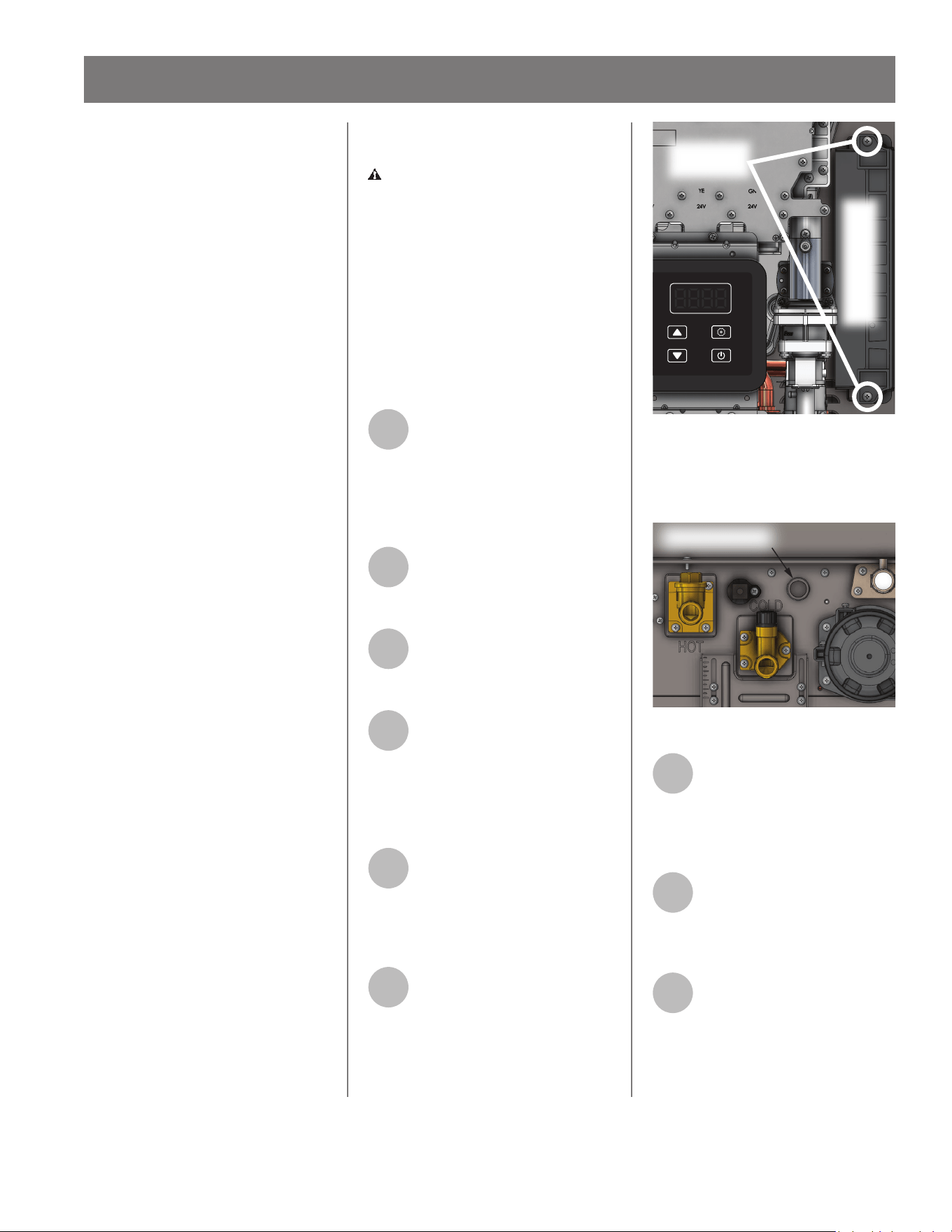
Cascade System
The Cascade System allows up to 12
heaters of the same input rate and
model to be linked in a Parent/Child
conguraon. DO NOT link heaters
with dierent input rates or dissimilar
models together. DO NOT link heaters
for indoor and outdoor applicaons
together.
IMPORTANT: Failure to cascade
heaters of the same input rate and
model series will result in a system
error code.
The Cascade System will acvate
heaters based on the system ow
rate demand. When system demand
increases or decreases, the cascade
system will acvate/deacvate
heaters as needed to balance ow
through the heaters.
The Parent heater determines when
to acvate/deacvate heaters. The
order of heater acvaon is set by
the Parent heater and will sequence
the heaters in order from the least
combuson hours to the most. This
allows for even operaon of all the
water heaters in the cascade system.
The heaters will deacvate in the
reverse order that they are acvated,
meaning if Child Heater 11 was the
last to turn on, it will be the rst
to turn o when system demand
decreases. The Parent heater will
reorder the sequence on a weekly
basis.
The new sequence of acvaon will
start with the heater that has the
least combuson hours to the most.
Each heater will acvate based on
predetermined ow rate factors.
These factors vary based on heater
model.
If any child heater encounters an error
code, the cascade system will bypass
that heater and connue to operate.
If the Parent heater loses power, then
the cascade system deacvates. The
user will need to change the sengs
of one of the other heaters to be the
Parent or resolve the issue of the
Parent heater.
WARNING! Working on an
energized circuit can result in severe
injury or death from electrical shock.
IMPORTANT: Each water heater
must be properly congured for
Altude (C01), Vent Type (C08) and
Vent Length (C02) before linking the
units in the Cascade system. See
the "Conguraon Mode (C Mode)"
secon on page 50 for informaon
on how to properly congure the
water heaters.
1
The Cascade system should
be congured with the Parent
water heater as either the
rst or last in the series of water
heaters connected to the cold water
supply. The Child units will follow
sequenally. See Figure 31.
2
Before proceeding,
disconnect electrical power
to all water heaters in the
Cascade conguraon.
3
Remove the front covers and
keep the two screws from
both the Parent and Child
water heaters for re-installaon.
4
Remove the two screws (top
and boom) securing the
control panel to the Parent
water heater. The control panel is
located on the boom right side of
the water heater as shown in Figure
29.
5
Gently slide control panel out
from the Parent water heater
to gain access to the Printed
Circuit Board (PCB). Proceed with
cauon and DO NOT disconnect wires
from PCB.
6
Use Figure 30 to locate the
rubber access grommet on
the boom of the water
heater. Route the single harness end
of the Cascade Linking Cable through
the boom and around to the circuit
board.
Remove
Screws (2x)
Control Panel for
Printed Circuit Board
ON/OFF
DOWN
UP SETTING
Figure 29 - Control Panel Locaon
NOTICE: The cable should be routed
under the circuit board assembly to
prevent strain on the wiring harness.
Rubber Grommet
Figure 30 - Boom of water heater - Grommet
7
Use Figure 31 as a reference
to locate the connecon
point for the Parent Cascade
Unit. Use the single harness end of
the Cascade Linking Cable to make the
inial connecon.
8
Follow steps 4-6 to route the
double harness end of the
Cascade Linking Cable to the
printed circuit board on the rst Child
water heater.
9
If more than one Child water
heater is used, then route the
single harness end of the
second Cascade Linking Cable through
the rubber grommet on the boom of
the rst Child water heater and
connect it to the open harness on the
44 • Residenal Non-Condensing Gas Tankless Water Heater Use and Care Guide
INSTALLATION
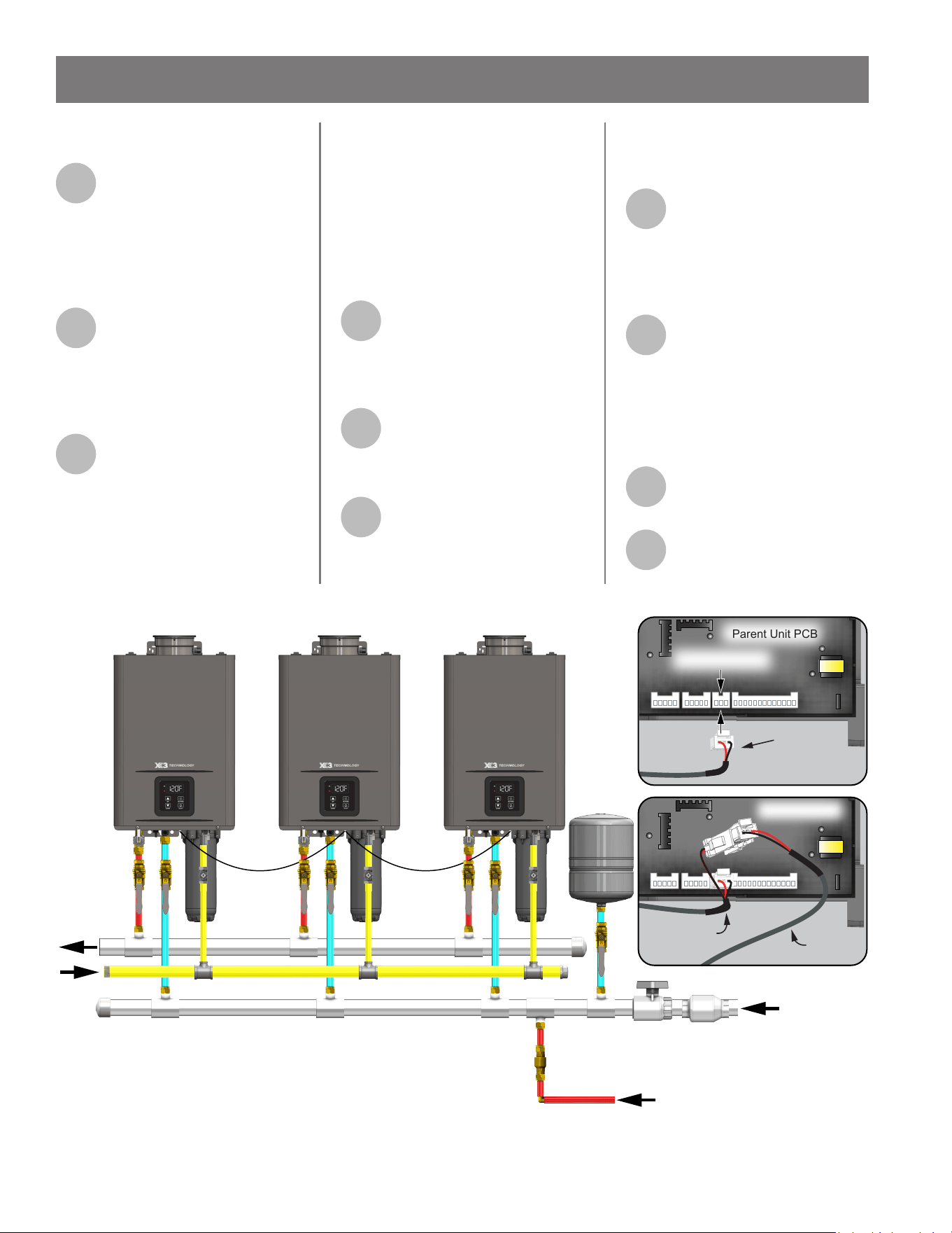
Residenal Non-Condensing Gas Tankless Water Heater Use and Care Guide • 45
rst Cascade Linking Cable as shown
in Figure 31.
10
Once all connecons are
made, the water heaters
must be assigned their
posion in the system. Turn on the
power supply to all of the water
heaters, making sure there is no water
ow.
11
On the Parent water heater
simultaneously press and
hold the "SETTING" and "UP"
buons unl C00 appears. See the
"Conguraon Mode (C Mode)"
secon and Table 21 on page 51.
12
Press the UP arrow buon to
reach the C13 opon, then
press the "SETTING" buon
to enter that opon.
NOTICE: C13 denes the number
of Child water heaters that will be
connected to the parent unit.
Enter the number of Child water
heaters aached to the parent water
heater and press the "SETTING"
buon to load the number to
memory. For example, if the system
consists of four total water heaters,
then enter 3 for three child heaters
into C13. Press the "SETTING" buon
again to return to normal operaon.
13
Aer the Parent water heater
is congured, the Child water
heaters must be congured.
Perform the following steps on each
Child water heater.
14
On each Child unit’s display,
press and hold both the
"SETTING" and "UP" buons
unl C00 appears.
15
Press the UP arrow buon to
reach the C14 opon, then
press the "SETTING" buon
to enter that opon.
NOTICE: C14 denes the number
assigned to each Child water heater
connected to the parent water heater.
16
Enter number 2 for the rst
Child water heater and press
the "SETTING" buon to load
the number to memory. Repeat this
step assigning a sequenal number to
each addional Child water heater.
17
Press and hold the "SETTING"
and "UP" buons again to
return to normal operaon.
NOTICE: A maximum 11 Child water
heaters can be connected to a
Cascade System of 12 total water
heaters.
18
Verify all electrical
connecons and conduit
connecons are secure.
19
Follow the instrucons in the
Geng Started secon of this
manual.
INSTALLATION
BUILDING
RETURN
PARENT UNIT
CWS
HWS
GAS
CHILD UNIT #1 CHILD UNIT #2
Single
Harness
End
Parent Unit PCB
3-Pin Connector
Double
Harness End
Child Unit PCB
Single
Harness
End
Figure 31 - Mul Unit Cascade Conguraon
46 • Residenal Non-Condensing Gas Tankless Water Heater Use and Care Guide
FOR YOUR SAFETY,
READ BEFORE
OPERATING
WARNING! IF YOU SMELL GAS:
• DO NOT try to start the water
heater.
• DO NOT touch any electric switches.
• DO NOT use any phone in your
building.
• Immediately call your gas supplier
from a neighbor's phone. Follow the
gas supplier's instrucons.
• If you cannot reach your gas suppli-
er, call the re department.
• Failure to observe these warnings
could lead to re or an explosion,
resulng in severe injury or death.
✓ Check the GAS and WATER CON-
NECTIONS for leaks before ring
unit for the rst me.
✓ Open the main gas supply valve to
the unit using only your hand to
avoid any spark. Never use tools. If
the knob will not turn by hand,
DO NOT try to force it; call a qual-
ied service technician. Forced re-
pair may result in a re or explosion
due to gas leaks.
✓ Be sure to check for the presence
of leaking gas toward the boom
of the unit because some gases
are heavier than air and may sele
towards the oor.
✓ Check the GAS PRESSURE. Refer
to the "Gas Supply and Gas Pipe
Sizing" secon on page 33.
✓ Check for PROPER VENTING and
COMBUSTIBLE AIR to the water
heater.
✓ Purge the GAS and WATER LINES to
remove any air pockets.
✓ DO NOT use this appliance if any
part has been under water. Immedi-
ately contact a qualied installer or
service agency to replace a ooded
water heater. DO NOT aempt to
repair the unit! It must be replaced!
Start-Up Instrucons
Read and understand these direcons
thoroughly before aempng to
start-up the water heater. Make
sure the water is plumbed correctly
before aempng to start-up the
water heater. Check the rang plate
near the gas control valve to ensure
the correct gas type. DO NOT use
this water heater with any gas other
than the one listed on the data plate.
If you have any quesons or doubts,
consult your gas supplier or gas ulity
company.
NOTICE: A newly installed water
heater will have air in the gas line. It
may take several aempts to clear all
the air from the gas line.
1
Make sure the manual gas
valve for the water heater's
supply line is ON.
2
Plug the water heater into a
grounded 120 VAC outlet, or
acvate the breaker/
disconnect, if the water heater is
hardwired.
3
The user interface module
(UIM) or remote controller
will display the current
temperature seng. The default is
120°F.
4
To change the set point
temperature, press the "UP"
or "DOWN" buon to raise or
lower the outlet temperature. See the
"Temperature Sengs" secon on
page 49.
5
To set the heater to the
appropriate elevaon, vent
type and vent length, see
"Conguraon Mode (C Mode)"
starng on page 50.
Shut-Down Instrucons
Press the "ON/OFF" buon and wait
for the display to shut o.
NOTICE: The power buon on the
water heater and remote controller
DOES NOT disconnect power to the
water heater. You must physically
disconnect power to the water heater.
Emergency Shut-Down
Should overheang occur or the gas
supply fail to shut o, follow these
steps:
1
Turn OFF the gas supply to
the water heater at the
manual shut-o valve.
2
Press the "ON/OFF" buon
on the water heater.
3
Disconnect power to the
water heater by unplugging it
or by turning o the circuit at
the breaker box, as appropriate.
4
Call a qualied person
(licensed plumber, authorized
gas company personnel, or
authorized service technician) for
assistance.
OPERATION
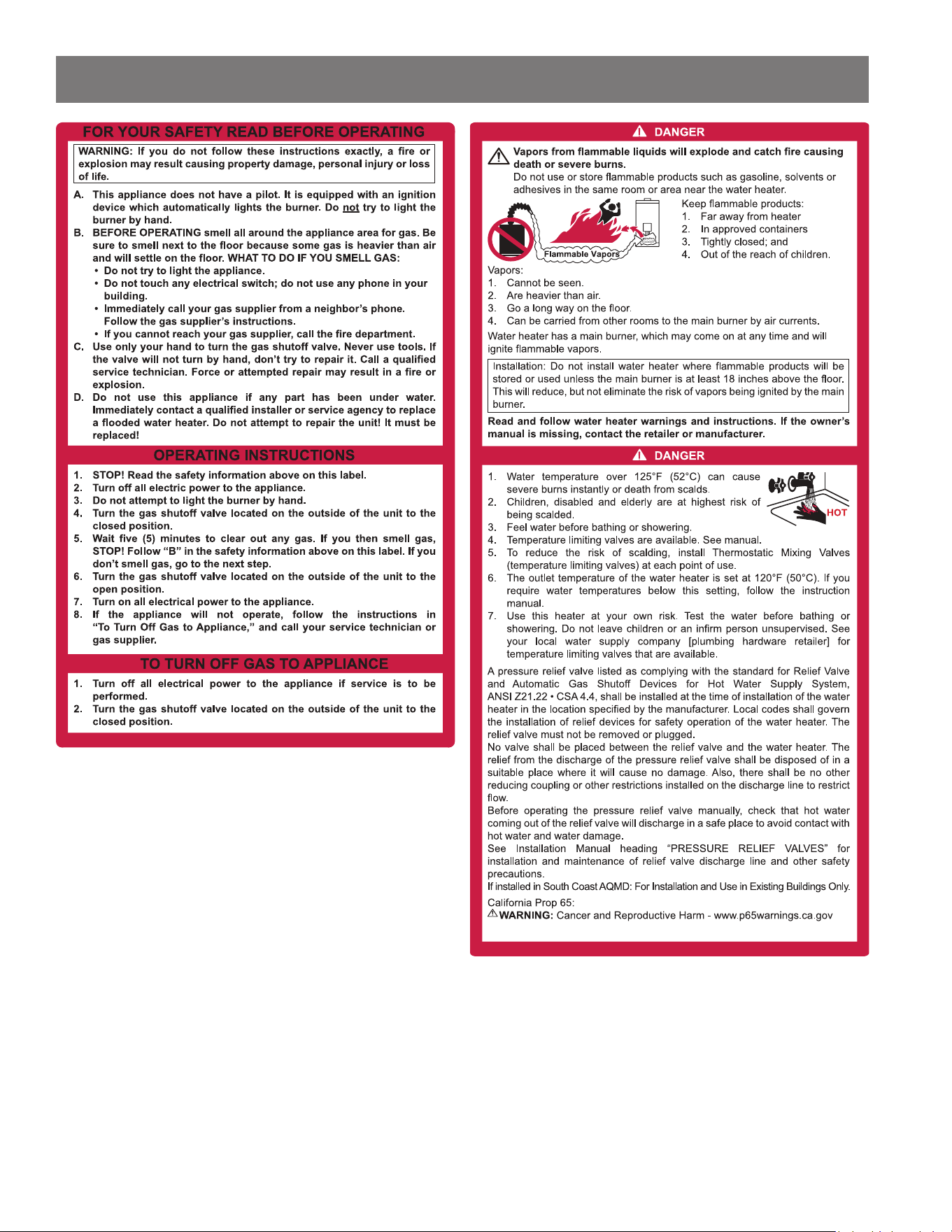
Figure 32 - Lighng Instrucons
Residenal Non-Condensing Gas Tankless Water Heater Use and Care Guide • 47
OPERATION
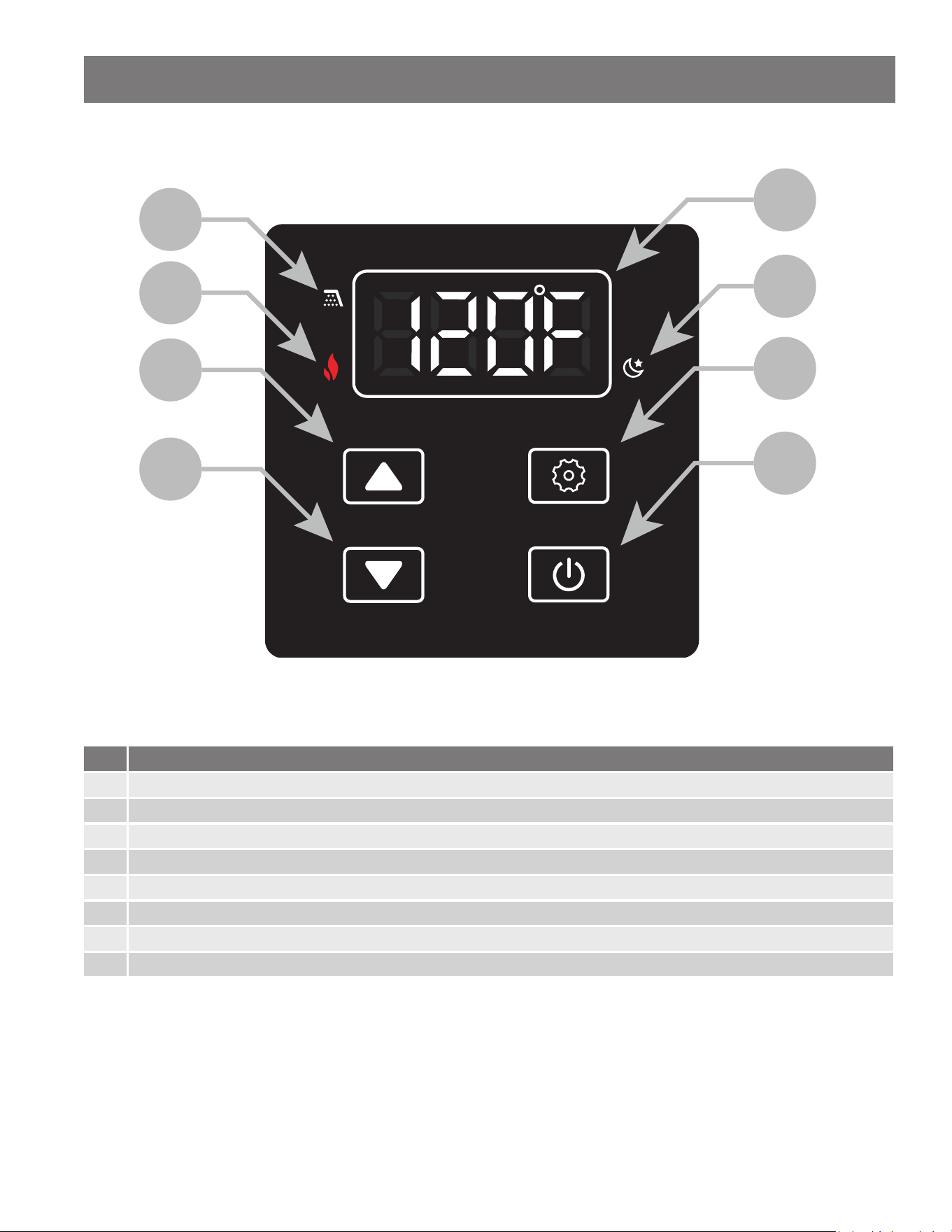
48 • Residenal Non-Condensing Gas Tankless Water Heater Use and Care Guide
User Interface Module (UIM) & Remote Controller Display Overview
ON/OFF
DOWN
UP SETTING
E
F
G
H
B
A
C
D
Figure 33 - UIM & Remote Controller Display Diagram
Table 15: UIM & Remote Controller Display
Item Descripon
A Water Flow Detected
B Flame Detected
C Up Buon
D Down Buon
E Display
F Standby Mode
G Seng Buon
H Operaon ON/OFF Buon
OPERATION
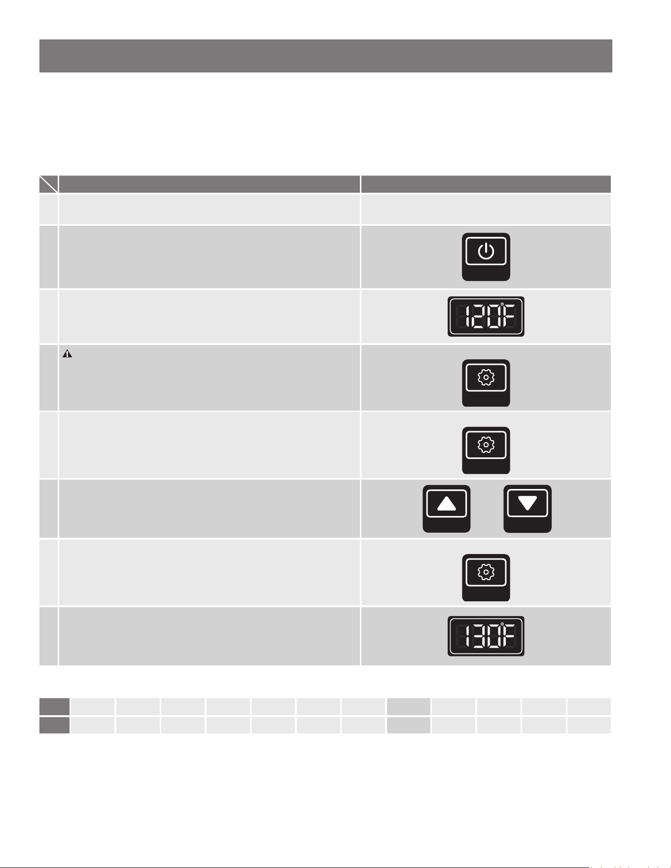
Residenal Non-Condensing Gas Tankless Water Heater Use and Care Guide • 49
OPERATION
Temperature Sengs
With the installaon steps completed, you may adjust the water heater's temperature seng if desired. The water temperature
set point is factory set to 120°F. The temperature set point may be increased or decreased by simply pressing the "UP" buon or
the "DOWN" buon. To set the water heater to a temperature above 125°F, follow the procedure as outlined in Table 16:
Table 16: Set Temperature Above 125°F (52°C)
Operaon Screen on the Controller (Built-in & Remote)
1. Turn on the 120 VAC power supply to the unit.
2.
Press the "ON/OFF" buon on the controller in order to turn the
controller on.
ON/OFF
3.
The set point temperature will display as shown in the picture on
the right (Example: 120°F).
4.
WARNING! Higher temperatures increase the risk of scalding,
but even at 120°F (49°C), hot water can scald (page 10).
Press and hold the "SETTING" buon for 5 seconds to access the
water heater Adjustment Mode (A Mode).
LONG PRESS
SETTING
5.
The display will ash between code "A00" and the current set
temperature. Short press the "SETTING" buon to access the
temperature seng. The temperature only will ash.
SHORT PRESS
SETTING
6.
Press the "UP" buon and the "DOWN" buon to select the
desired set point temperature. See Table 17 below for available
set point temperatures.
UP
DOWN
7. Short press the "SETTING" buon again to execute the change.
SHORT PRESS
SETTING
8.
Press and hold the "SETTING" buon for 5 seconds to return the
display to normal operaon. The new temperature set point will
appear (Example: 130°F).
Table 17: Water Heater Temperature Set Points
°F 100 102 104 106 108 110 115 120* 125 130 135 140
°C 38 39 40 41 42 43 46 49* 52 54 57 60
*Factory seng (Default): 120°F

50 • Residenal Non-Condensing Gas Tankless Water Heater Use and Care Guide
OPERATION
Conguraon Mode (C Mode)
The water heater must be congured based on the installaon applicaon. If the installaon meets all of the “Default” criteria
listed, then no adjustments are necessary. Follow the procedure below to access C Mode and to properly congure the water
heater:
1. Press and hold the "UP" buon and the "SETTING" buon for 5 seconds to access C Mode.
2. Press the "UP" buon or the "DOWN" buon to search for the desired C Mode.
3. Press the "SETTING" buon to adjust the value. The current value will ash. Use the "UP" and "DOWN" buons to adjust
the seng to the value listed in the applicable table below.
4. Press the "SETTING" buon again to conrm the new value selected is correct.
5. To adjust addional modes, press the "UP" buon or the "DOWN" buon to search for the desired C Mode. To exit C Mode,
press and hold the "UP" buon and the "SETTING" buon for 5 seconds.
IMPORTANT: If any C08 (Vent Type) value is selected and conrmed, the User Interface Module will display the water heater
model number preceded by a dash. The water heater MUST be disconnected at the power supply and reconnected to save the
C08 selecon. This acon may take place aer all conguraon adjustments are complete.
Table 18: C Mode Altude Sengs (C01)
Code Descripon Seng Indoor Model Outdoor Model Conguraon Opons
C01 Altude Sengs
0 Default Default 0-2000 Elevaon
1 Available Available 2001-5400 Elevaon
2 Available N/A 5401-7800 Elevaon
Notes for Proper Conguraon (Indoor/Outdoor):
1) C01 (Altude) MUST be adjusted before C08 (Vent Type) and C02 (Vent Length).
2) The Outdoor Model does not require further adjustment to C08 (Vent Type) or C02 (Vent Length).
3) If your applicaon meets the Default criteria, then no adjustment to C01 (Altude) is required.
Table 19: C Mode Vent Type (C08)
Code Descripon Seng Indoor Model Conguraon Opons
C08 Vent Type
2 Default Metal-Fab Corr/Guard®
3 Available CoxCentric®, Centrotherm, Ubbink
Notes for Proper Conguraon (Indoor):
1) C08 (Vent Type) MUST be adjusted before C02 (Vent Length).
2) When C01 (Altude) is set to 0, C08 (Vent Type) will default to seng 2 and cannot be adjusted.
3) When C01 (Altude) is set to either 1 or 2, select the appropriate C08 (Vent Type) value based on the listed venng above.
4) If your applicaon meets the Default criteria, then no adjustment to C08 (Vent Type) is required.
Table 20: C Mode Vent Length Conguraon (C02)
Code Seng Indoor Model Conguraon Opons
C02
0 Default 5-9
1 Available 9-27
2 Available 27-45
Notes for Proper Conguraon (Indoor):
1) C02 (Vent Length) MUST be adjusted last.
2) If your applicaon meets the Default criteria, then no adjustment to C02 (Vent Length) is required.
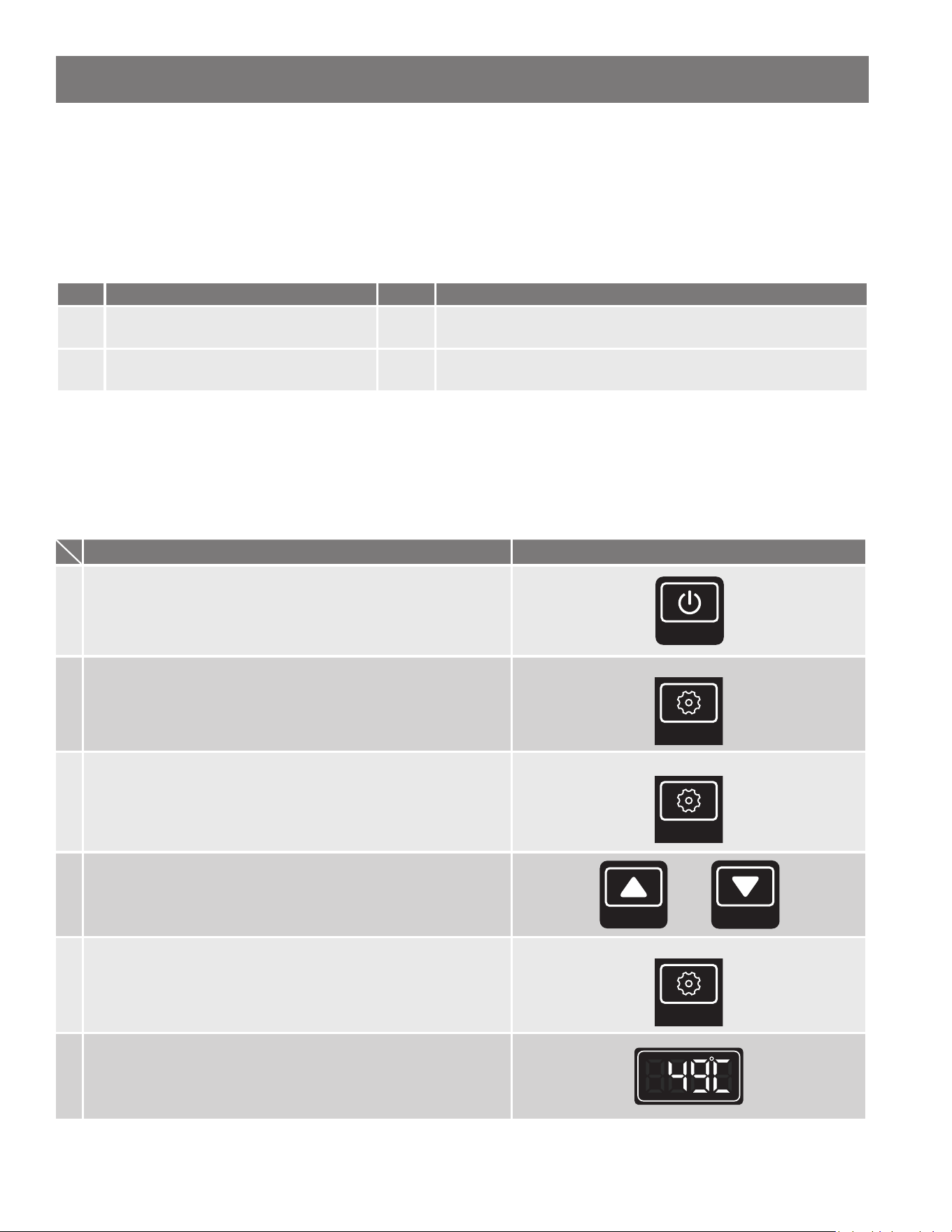
Residenal Non-Condensing Gas Tankless Water Heater Use and Care Guide • 51
OPERATION
Cascade Conguraon
Use Table 21 below to congure water heaters installed in a Cascade System. See the "Cascade System" secon on page 44 for
more informaon on installaon and conguraon.
IMPORTANT: Each water heater must be properly congured for Altude (C01), Vent Type (C08) and Vent Length (C02) before
linking the units in the Cascade system.
Table 21: C Mode Cascade System (C13 & C14)
Code Descripon Seng Conguraon Opons
C13 Number of Child Units in Cascade System
0:
1-11:
No Cascade System (default).
Idenfy number of Child Units. This acvates the Cascade System.
C14 Cascade System Heater ID Number
1:
2-12:
Parent Heater (default).
Individually set each Child Unit per user preference.
Unit Conversion Mode
Units of measurement can be changed from Imperial to Metric and vice versa. For example, temperature can be changed from
°F to °C. Flow rate will also change from gallons per minute to liters per minute when this seng is changed. Follow this
procedure to change this seng:
Table 22: Convert Units
Operaon Screen on the Controller (Built-in & Remote)
1.
Turn on the 120 VAC power supply to the unit. Press the "ON/
OFF" buon on the controller in order to turn the controller on.
ON/OFF
2.
The set point temperature will display. Press and hold the
"SETTING" buon for 5 seconds to access the water heater
Adjustment Mode (A Mode).
LONG PRESS
SETTING
3.
The display will ash between code "A00" and the current set
temperature. Press the "UP" or "DOWN" buon once and the
display will show code "A01." Short press the "SETTING" buon
to show the current temperature seng. The temperature will
ash.
SHORT PRESS
SETTING
4.
Press the "UP" buon and the "DOWN" buon to alternate
between Fahrenheit and Celsius.
UP
DOWN
5. Short press the "SETTING" buon again to execute the change.
SHORT PRESS
SETTING
6.
Long press the "SETTING" to return the display to normal
operaon. The new temperature set point will appear in the
selected unit (Example: 49°C).
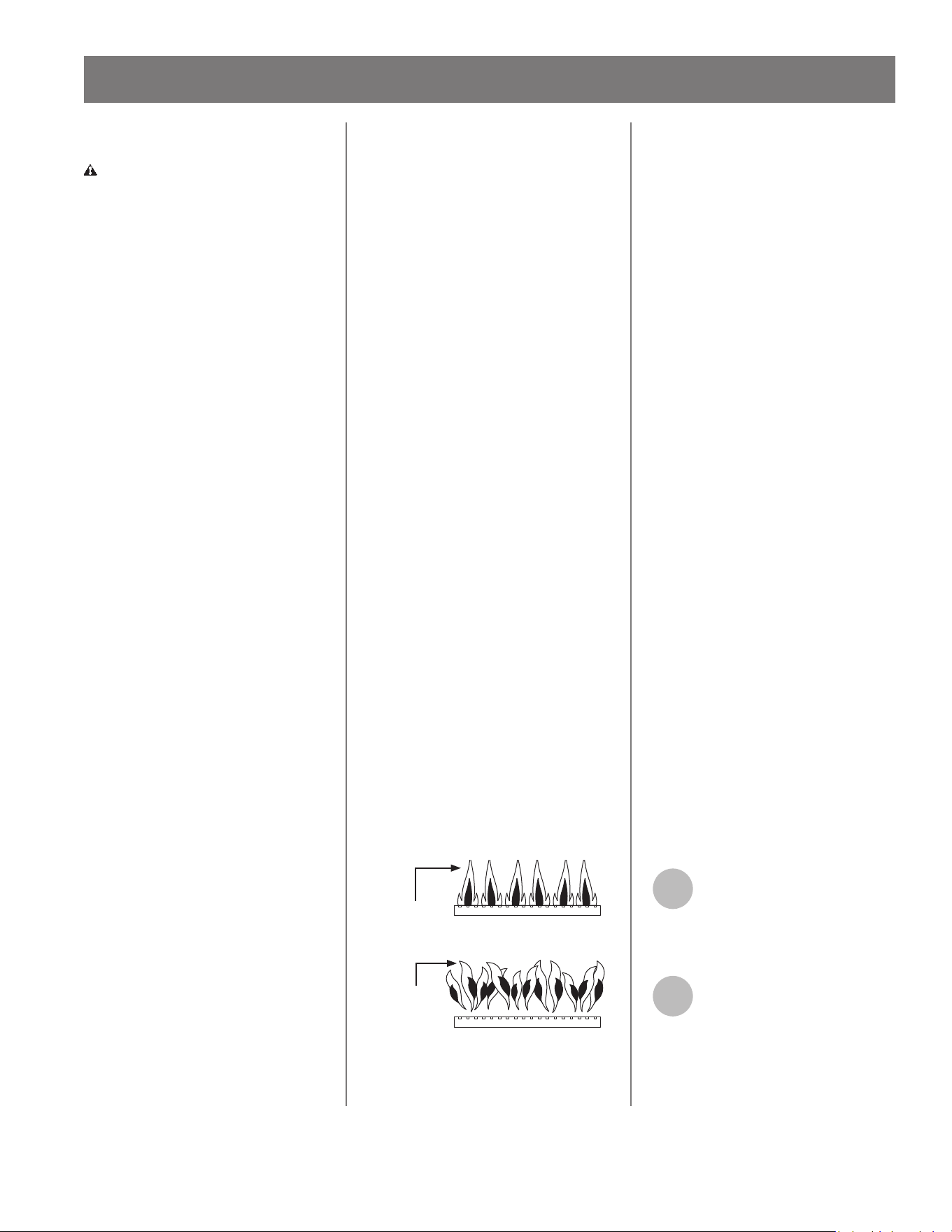
52 • Residenal Non-Condensing Gas Tankless Water Heater Use and Care Guide
Regular Maintenance
WARNING! Turn OFF the electrical
power supply and close the manual
gas shut-o valve and the manual
water control valve before servicing.
Failure to do so could result in
serious personal injury or death.
The manufacturer recommends
having the unit checked once a year or
as necessary by a licensed technician
or qualied person. If repairs are
needed, any repairs should be done
by a licensed technician.
Roune maintenance will help your
water heater last longer and work
beer. Failure to perform required or
recommended maintenance may void
the warranty. If you cannot perform
these roune maintenance tasks
yourself, contact a qualied person:
• Clean the cold-water inlet lter.
• Be sure that all openings for com-
buson and venlaon air are not
blocked. Any blockages detected
MUST be removed.
• The venng system for indoor model
water heaters should be checked
annually for any leaks, corrosion,
blockages or damage. Replace any
damaged secon of venng and
clear any blockages.
• The terminaon screen (if installed
in the venng system for indoor
model water heaters) MUST be
inspected regularly that it is not
blocked by any object and debris
including dust, dirt, snow, etc..
• Keep the area around the water
heater and terminaons clear. Reg-
ularly ensure that the area around
the water heater, vent terminaon,
and air intake is free from dust,
debris, and other contaminants.
Remove any combusble materials,
gasoline, ammable vapors, and
liquids.
• If the pressure relief valve discharg-
es periodically, it may be due to
thermal expansion in a closed water
supply system. Contact the water
supplier or local plumbing inspector
on how to correct this situaon.
• The pressure relief valve must be
manually operated periodically to
check for correct operaon. Before
operang the valve manually, check
that it will discharge in a place for
secure disposal.
• If a condensate drain system is
installed on an indoor model water
heater, then it must be inspected
regularly that it drains properly in
accordance with local codes or the
manufacturer's instrucons. If the
trap uses water to create the barrier,
verify there is sucient water in the
trap loop (Figure 12 & Figure 13).
• The burner should be checked annu-
ally for dust, lint, grease or dirt.
• Visually check the burner ames
through the burner window (sight
glass) on the burner assembly. The
burner assembly is located in the
middle of the water heater. A prop-
erly operang burner should pro-
duce clear, blue, stable ames. The
ames should not be liing above
the burner. Contaminated air may
cause a discolored ame. Contact a
qualied technician if the ame is
not sasfactory. See Figure 34 below
for burner ame reference.
Blue Flame
Satisfactory
Flame lifting
above the
burner
Unsatisfactory
Figure 34 - Check Burner Flames
Freeze Protecon
System
This unit comes equipped with
heang blocks to protect it from
damage associated with freezing. The
auto-re mode acvates the burner
for a short period of me.
For this freeze protecon system to
operate, there must be electrical
power to the unit. Damage to the
heat exchanger caused by freezing
temperatures due to power loss is
not covered under the warranty. In
cases where power losses can occur,
consider the use of a backup power
supply.
It is the installer's responsibility
to be aware of freezing issues and
take all preventave measures. The
manufacturer will not be responsible
for any damage to the heat exchanger
as a result of freezing.
NOTICE: Only pipes within the water
heater are protected by the freeze
protecon system. Any water pipes
(hot or cold) located outside the
unit will not be protected. Properly
protect and insulate these pipes from
freezing. See “Available Accessories”
on page 21 for the Cartridge Freeze
Protecon Kit. This kit is only available
for X3® models.
If you will not be using your heater
for a long period of me or power has
been lost during freezing condions:
1
Completely drain the water
out of the unit. See the "Unit
Draining & Power Outage
(Freeze Protecon)" secon on page
53.
2
Disconnect power to your
water heater.
MAINTENANCE
Residenal Non-Condensing Gas Tankless Water Heater Use and Care Guide • 53
MAINTENANCE
Unit Draining &
Power Outage (Freeze
Protecon)
1
Close the manual gas shut-o
valve.
2
Disconnect power to the
water heater by unplugging it
or by turning o the circuit at
the breaker box.
3
Close the cold inlet water
valve.
4
Open all hot water taps in the
house. When the residual
water ow has ceased, close
all hot water taps.
5
Drain the X3® Cartridge: Have
a bucket or pan to catch
water from the X3® Cartridge.
To remove the X3® Cartridge, remove
and keep the 3 screws securing the
cartridge in place. Pull down to
remove it from the water heater.
Empty the water out of the cartridge
into the bucket.
6
Wait a few minutes to ensure
all water has completely
drained from the unit.
7
Keep the cold water valve
closed. Keep the gas valve
closed. Keep supply power
disconnected.
8
To restore the unit to
operaon, reinstall the X3®
Cartridge with 3 screws
removed earlier. For detailed
instrucons, see “X3® Cartridge
Installaon” on page 36.
9
Open the cold inlet water
valve. Check all water
connecons for leaks. If leaks
are found, shut o the cold water inlet
valve and immediately x any leaks. If
no leaks are present proceed to the
next step.
10
Reconnect power to the
water heater.
11
Open the manual gas shut-o
to the water heater.
12
If the set temperature is not
displayed, press the ON/OFF
buon.
NOTICE: If any errors occur, shut o
the water immediately.
Inlet Water Filter
1
Close the manual gas shut-o
valve.
2
Disconnect power to the
water heater by unplugging it
or by turning o the circuit at
the breaker box.
3
Close the inlet water valve.
4
Open all hot water taps in the
house. When the residual
water ow has ceased, close
all hot water taps.
5
Drain the X3® (or Bypass)
Cartridge: Have a bucket or
pan to catch water from the
X3® Cartridge. To remove the X3®
Cartridge, remove and keep the 3
screws securing the cartridge in place.
Pull down to remove it from the water
heater. Empty the water out of the
cartridge into the bucket.
6
Wait a few minutes to ensure
all water has completely
drained from the unit.
7
Unscrew the inlet water lter
and remove it from the water
heater.
8
Clean the lter: Check the
water lter located within the
cold inlet. With a ny brush,
clean the water lter of any debris
which may have accumulated.
9
Screw the inlet water lter
back into place. Hand- ghten
only.
NOTICE: Handle with care and verify
the O-ring is not dirty or damaged.
10
To restore the unit to
operaon, reinstall the X3®
Cartridge with 3 screws
removed earlier. For detailed
instrucons, see “X3® Cartridge
Installaon” on page 36.
11
Turn ON the cold water
supply to the water heater at
the cold inlet valve. The
system will fully pressurize and any
leaks at water connecons will be
apparent. Correct any leaks
immediately.
12
Turn ON the gas supply to the
water heater at the manual
gas shut o valve.
13
Restore power to the water
heater. The water heater is
now ready for operaon.

54 • Residenal Non-Condensing Gas Tankless Water Heater Use and Care Guide
General Troubleshoong
If the water heater is experiencing issues, please check the following. Aer checking, consult with a qualied person.
Table 23: Troubleshoong Chart
Problem Soluons
Temperature and Amount of Hot Water
It takes a long me to get hot water at the
xtures.
• The me it takes to deliver hot water from the water heater to your
xtures depends on the length of piping between the two. The longer
the distance or the bigger the pipes, the longer it will take to get hot
water.
• If you would like to receive hot water to your xtures more quickly, you
may want to consider a hot water recirculaon system.
The water is not hot enough.
• Compare the ow and temperature.
• Check cross plumbing between the cold water lines and hot water
lines.
• Is the gas supply valve open fully?
• Is the gas line sized properly?
• Is the gas supply pressure sucient?
• Is the temperature seng too low?
• Check if the Point-of-Use mixing valves are set correctly, if they are
installed.
• Are the exhaust and air inlets free of debris? If not, clear the debris
and any blockage(s).
The water is too hot. • Is the set point temperature set too high?
The hot water is not available when a xture
is opened.
• Make sure the unit has 120 VAC, 60 Hz power supply.
• If you are using the remote controller and/or temperature controller, is
the power buon turned on?
• Is the gas supply valve fully open?
• Is the water supply valve fully open?
• Is the lter on the cold water inlet clean?
• Is the hot water xture suciently open to draw at least 0.4 GPM
(1.5 L/min) through the water heater?
• Is the unit frozen?
• Are the exhaust and air inlets free of debris? If not, clear the debris
and any blockage(s).
The hot water runs cold and stays cold.
• Is the ow rate enough to keep the water heater running?
• If there is a recirculaon system installed, does the recirculaon line
have enough check valves?
• Is the gas supply valve fully open?
• Is the lter on the cold water inlet clean?
• Are the xtures clean of debris and obstrucons?
Fluctuaon in hot water temperature.
• Is the lter on the cold water inlet clean?
• Is the gas line sized properly?
• Is the gas supply pressure sucient?
• Check for cross connecon between cold water lines and hot water
lines.
• If cascaded with mulple heaters, inspect and verify each heater is
operang properly within the cascade system.
TROUBLESHOOTING

Residenal Non-Condensing Gas Tankless Water Heater Use and Care Guide • 55
TROUBLESHOOTING
Table 23: Troubleshoong Chart
Problem Soluons
Water Heater
Unit does not ignite when water goes
through the unit.
• Is the ow rate over 0.4 GPM (1.5 L/min)?
• Check the lter on the cold water inlet.
• Check for reverse connecons and cross connecon.
• If you use the remote controller and/or built-in controller, is the power
buon turned on?
• Check if the inlet water temperature is too high. If it is too close to the
set temperature, the water heater will not acvate.
The fan motor is sll spinning aer operaon
has stopped.
• This is normal. Aer operaon has stopped, the fan motor keeps run-
ning to re-ignite quickly, as well as to purge all the exhaust gas out of
the ue.
Unit sounds abnormal while in operaon.
• Check all venng and terminaons for any blockage and clear.
• If other exhaust terminaons are nearby, conrm ue gases are not
sucked into the water heater's air intake.
• Contact Technical Support Department.
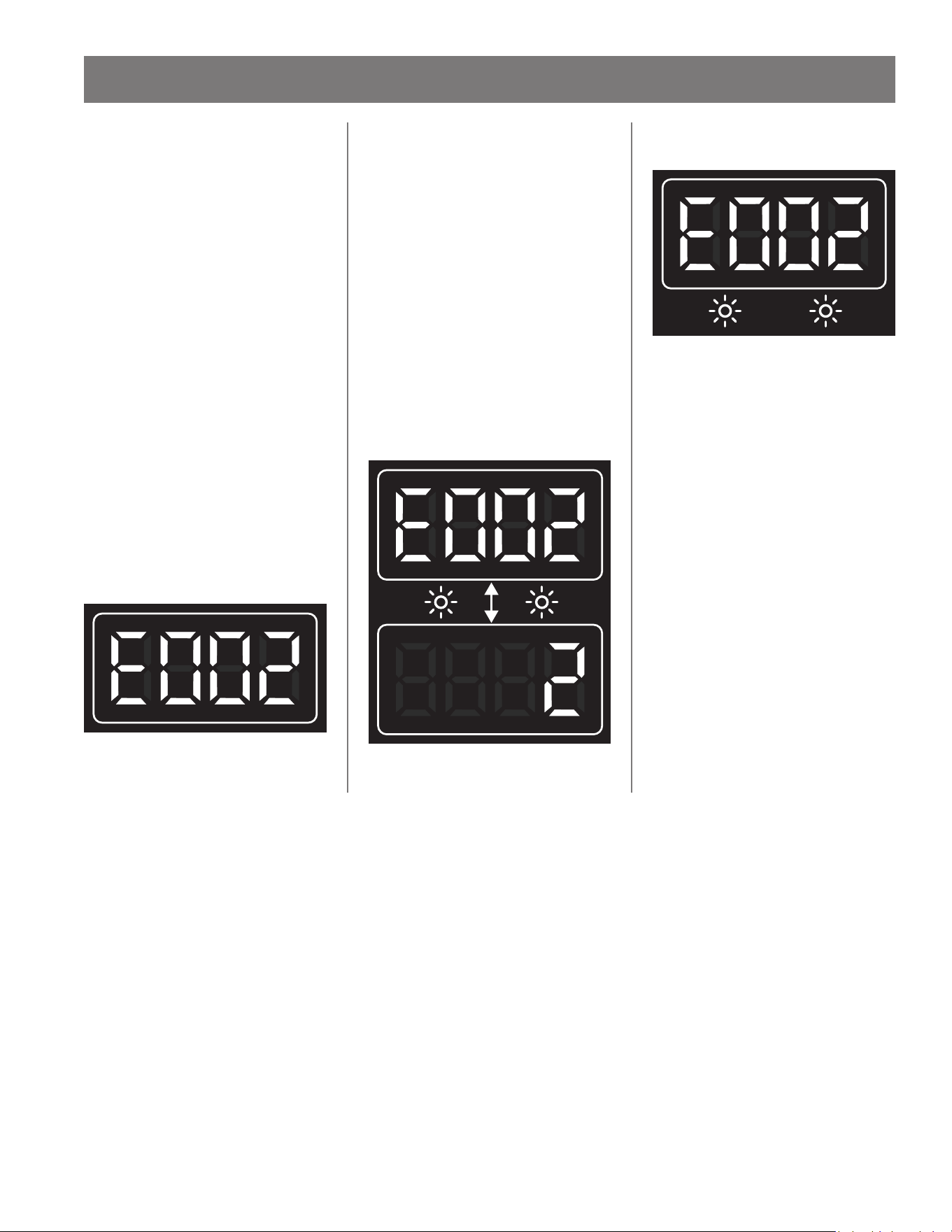
56 • Residenal Non-Condensing Gas Tankless Water Heater Use and Care Guide
Error Codes
The water heater has self-diagnosc
funcons for safety and convenience
when troubleshoong.
If there is a problem with the
installaon or the unit, the error code
associated with that failure will be
displayed on the built-in controller or
remote controller.
Consult Table 24 on the following
pages for the descripon of each error
code.
Single Unit Installaon
(Example)
If your water heater has the "E002"
error code (which signies a high limit
break):
• Indicator on the built-in and/or
remote controller will display "E002"
on the screen.
Figure 35 - Single Unit Error Code Example
Cascade System
(Example)
Error codes will be displayed
dierently with units installed within
a Cascade System, not only to show
what the error code is, but to also
indicate which unit within the system
has the error code. Below is a sample
of how the error code "E002" is
displayed in a Cascade System.
If Unit #2 has the "E002" error code
(which signies a high limit break):
• Indicator on the built-in and/or
remote controller of Parent unit will
intermiently ash "E002" and "2."
Figure 36 - Cascade System Error Code Example
(Parent Unit)
• Child unit #2 will intermiently ash
"E002" on the display.
Figure 37 - Cascade System Error Code Example
(Child Unit)
• Other Child units will not display
anything as the error code does not
pertain to them.
TROUBLESHOOTING
Residenal Non-Condensing Gas Tankless Water Heater Use and Care Guide • 57
TROUBLESHOOTING
Fault Analysis of Error Codes
If the water heater is displaying an error code, please check the following. Aer checking, consult with the manufacturer.
Table 24: Error Code Fault Analysis
Error
Code
Error Descripon Procedure
E002 High Limit Break
Manual Hi-Limit Switch located on heat exchanger tripped. Check Hi-limit switch
for proper operaon. Pressing the reset buon (center of the switch), will reset the
Hi-limit switch.
NOTICE: If the Hi-Limit switch has tripped, you will hear and feel it click when
reseng it. If the high limit switch connues to trip, contact a qualied service
technician.
E006
PCB Hardware Fault - Ad
Converter Fault
Check PCB wiring for loose, damaged or cut wires/connectors. Correct any loose
connecon and replace any damaged wires/connectors. If all wires/connectors are
intact, replace the PCB.
E010 Frequency Fault
PCB has detected an incorrect power supply frequency. Note the default frequency
is 60 Hz. See instrucons on page 50 to access C Mode. Conrm C07 displays
60. If the seng is correct and the error sll occurs, contact a qualied service
technician.
E011
PCB Hardware Fault - Memory
Error
The water heater will connue to operate while this error code is ashing. If this
heater is part of a cascade system, then the system will be aected based on the
heater’s seng.
• Parent Heater: The cascade system will not operate. Remove this heater from the
cascade system and set a dierent heater as the Parent.
• Child Heater: This heater will not operate. The rest of the cascade system will
connue to run.
E036 Flame Failure
WARNING! Working on an energized circuit can result in severe injury or death
from electrical shock.
Check the ame sensor wire for a short or disconnecon. Correct any loose
connecon and replace any damaged wire/connector. If the error sll occurs,
contact a qualied service technician.
E037
False Flame Detecon
(During Standby)
WARNING! Working on an energized circuit can result in severe injury or death
from electrical shock.
1. Check for a visible ame through the sight glass while water is not running
through the water heater. If the error sll occurs, immediately shut o the
water heater and contact a qualied service technician.
2. Check the ame sensor wire for a short or disconnecon. Correct any loose
connecon and replace any damaged wire/connector. If the error sll occurs,
contact a qualied service technician.
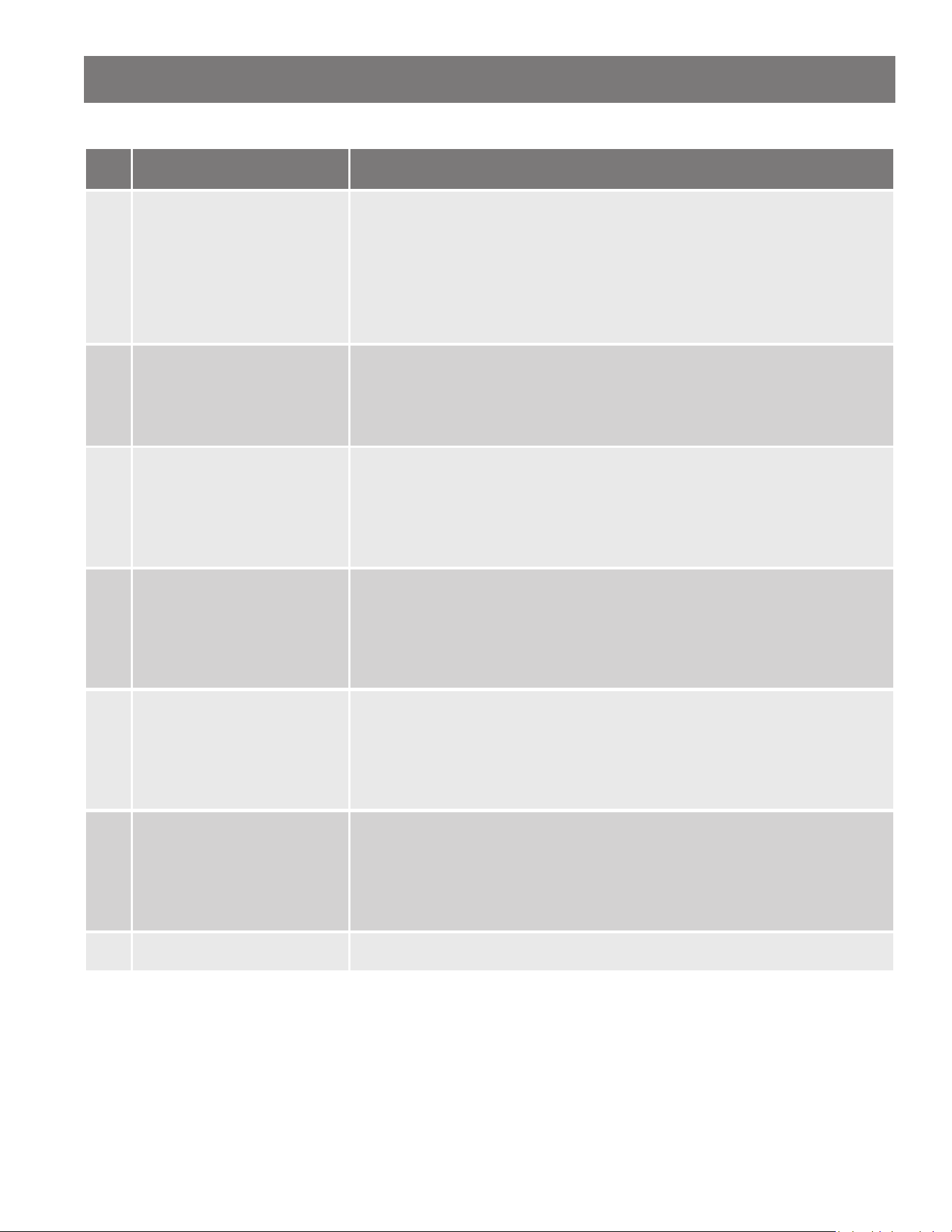
58 • Residenal Non-Condensing Gas Tankless Water Heater Use and Care Guide
Table 24: Error Code Fault Analysis
Error
Code
Error Descripon Procedure
E038 Ignion Failure
WARNING! Working on an energized circuit can result in severe injury or death
from electrical shock.
1. Check for a visible ame through the sight glass.
2. Check the ame sensor wire for a short or disconnecon. Correct any loose
connecon and replace any damaged wire/connector. If the error sll occurs,
contact a qualied service technician.
E041 Outlet Water Over-temp
1. Verify the thermistor reading with the water outlet temperature.
2. Remove the outlet thermistor (do not lose the O-ring) and check for any dirt or
debris. Clean with an Emery cloth. If the thermistor is damaged, replace it. If
the error sll occurs, contact a qualied service technician.
E049 Fan Thermistor Failure
1. Remove the thermistor (do not lose the O-ring) and check for any dirt or debris.
Clean with an Emory cloth. If the thermistor is damaged, replace it.
2. Check the Thermistor sensor wire for a short or disconnecon. Correct any
loose connecon and replace any damaged wire/connector. If the error sll
occurs, contact a qualied service technician.
E050 Inlet Thermistor Failure
1. Remove the thermistor (do not lose the O-ring) and check for any dirt or debris.
Clean with an Emory cloth. If the thermistor is damaged, replace it.
2. Check the Thermistor sensor wire for a short or disconnecon. Correct any
loose connecon and replace any damaged wire/connector. If the error sll
occurs, contact a qualied service technician.
E051 Outlet Thermistor Failure
1. Remove the thermistor (do not lose the O-ring) and check for any dirt or debris.
Clean with an Emory cloth. If the thermistor is damaged, replace it.
2. Check the Thermistor sensor wire for a short or disconnecon. Correct any
loose connecon and replace any damaged wire/connector. If the error sll
occurs, contact a qualied service technician.
E052
Heat Exchanger Thermistor
Failure
1. Remove the thermistor (do not lose the O-ring) and check for any dirt or debris.
Clean with an Emory cloth. If the thermistor is damaged, replace it.
2. Check the Thermistor sensor wire for a short or disconnecon. Correct any
loose connecon and replace any damaged wire/connector. If the error sll
occurs, contact a qualied service technician.
E380 Incorrect Seng Contact a qualied service technician to replace the PCB.
TROUBLESHOOTING
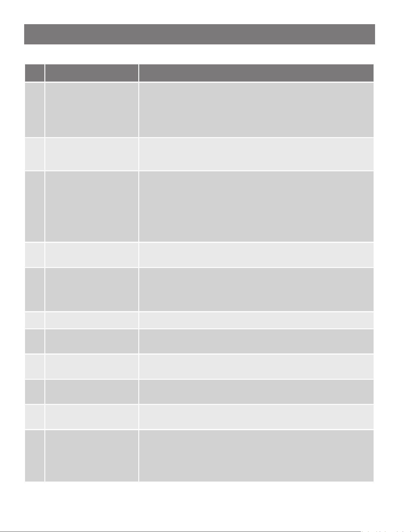
Residenal Non-Condensing Gas Tankless Water Heater Use and Care Guide • 59
TROUBLESHOOTING
Table 24: Error Code Fault Analysis
Error
Code
Error Descripon Procedure
E381 Combuson Blockage
1. With the water heater power disconnected, check the exhaust vent and air
intake piping for any blockages. Remove any blockages.
2. For indoor models, verify the water heater has sucient combuson air. Refer-
ence the "Venng (Indoor Model)" secon on page 24 of the manual.
3. If the error sll occurs, contact a qualied service technician.
E382
Abnormal Proporonal Valve
Current
Check the proporonal valve wiring. Correct any loose connecon and replace
any damaged wire/connector. If the error sll occurs, contact a qualied service
technician.
E383 Inlet Water Over-temp
1. Verify the inlet water temperature is not above the water heater's set tempera-
ture or above 122°F.
2. Remove the thermistor (do not lose the O-ring) and check for any dirt or debris.
Clean with an Emory cloth. If the thermistor is damaged, replace it.
3. Check the Thermistor sensor wire for a short or disconnecon. Correct any
loose connecon and replace any damaged wire/connector. If the error sll
occurs, contact a qualied service technician.
E385
Main Gas Solenoid Valve Drive
Circuit Failure
Check the gas valve wiring. Correct any loose connecon and replace any damaged
wire/connector. If the error sll occurs, contact a qualied service technician.
E388 Bypass Valve Fault
1. Correct any loose connecon and replace any damaged wire/connector.
2. Follow the draining procedure on page 53 to properly drain the water heater.
Remove the bypass valve and inspect for any debris or damage. Replace if
needed.
E389 Fan Current AD Failure Contact a qualied service technician to replace the PCB.
E390
Fan Over Max Current
(During Standby)
Check the fan motor wiring. Correct any loose connecon and replace any damaged
wire/connector. If the error sll occurs, contact a qualied service technician.
E391
Fan Over Max Current
(During Operaon)
Check the fan motor wiring. Correct any loose connecon and replace any damaged
wire/connector. If the error sll occurs, contact a qualied service technician.
E392
Fan False Start
(During Operaon)
Check the fan motor wiring. Correct any loose connecon and replace any damaged
wire/connector. If the error sll occurs, contact a qualied service technician.
E393 Fan Signal Loss
Check the fan motor wiring. Correct any loose connecon and replace any damaged
wire/connector. If the error sll occurs, contact a qualied service technician.
E394 Fan Target Speed
1. Check the fan motor wiring. Correct any loose connecon and replace any dam-
aged wire/connector.
2. With the water heater power disconnected, check the exhaust vent and air
intake piping for any blockages. Remove any blockages. If the error sll occurs,
contact a qualied service technician.
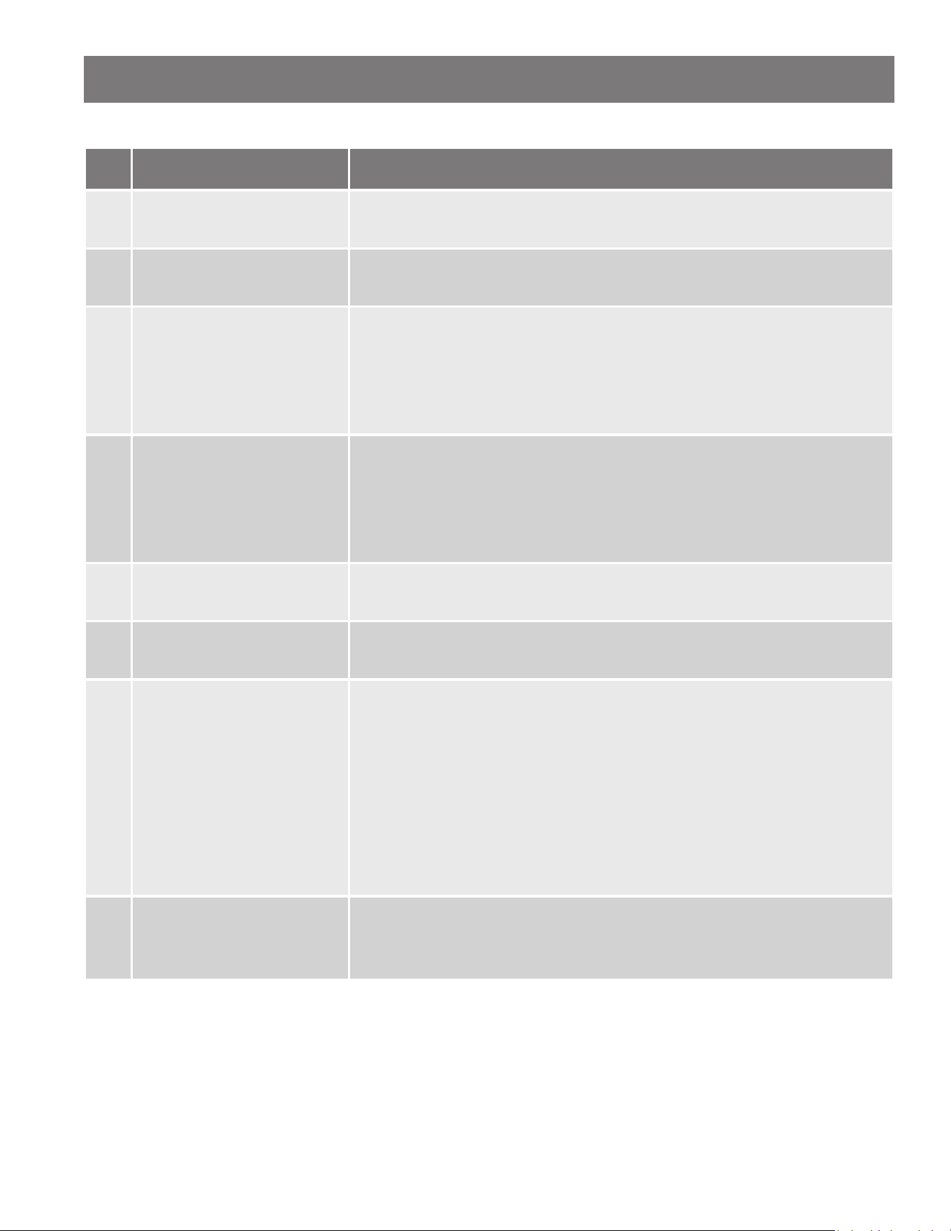
60 • Residenal Non-Condensing Gas Tankless Water Heater Use and Care Guide
TROUBLESHOOTING
Table 24: Error Code Fault Analysis
Error
Code
Error Descripon Procedure
E395
Fan Current without Drive
(During Standby)
Check the fan motor wiring. Correct any loose connecon and replace any damaged
wire/connector. If the error sll occurs, contact a qualied service technician.
E400
Communicaon Fault with UIM
(Indoor Model Only)
Check the UIM wiring. Correct any loose connecon and replace any damaged wire/
connector. If the error sll occurs, contact a qualied service technician.
E401
Communicaon Fault with
Remote Controller
1. Check the Remote Controller wiring. Correct any loose connecons and replace
any damaged wire/connector.
2. Only one remote controller can be installed, remove any addional remote
controllers.
3. If the error sll occurs, contact a qualied service technician.
E402
Communicaon Fault in
Cascade System
1. Check the Cascade wiring. Correct any loose connecons and replace any dam-
aged wire/connector.
2. Cycle the heater’s power OFF/ON if the cascade wiring was disconnected while
the system sll had power.
3. If the error sll occurs, contact a qualied service technician.
E404
Inconsistent Models in
Cascade-Link
Conrm all units in Cascade System are the same model. All models in the cascade
system must be the same.
E412
PCB Hardware Fault - Flame
Circuit Failure
Contact a qualied service technician to replace the PCB.
E413 Flame Sensor Fault
1. Check the ame sensor wire for a short or disconnecon. Correct any loose
connecon and replace any damaged wire/connector.
2. With the water heater power disconnected, check the exhaust vent and air
intake piping for any blockages. Remove any blockages.
3. For indoor models, verify the water heater has sucient combuson air. Refer-
ence the "Venng (Indoor Model)" secon on page 24 of the manual.
4. Check the installaon area for corrosive elements. Reference the Installaon
Environment secon in the manual.
5. If the error sll occurs, contact a qualied service technician.
E414 PCB - Flame Sensor Circuit
1. Check the ame sensor wire for a short or disconnecon. Correct any loose
connecon and replace any damaged wire/connector.
2. If the error sll occurs, contact a qualied service technician to replace the PCB.
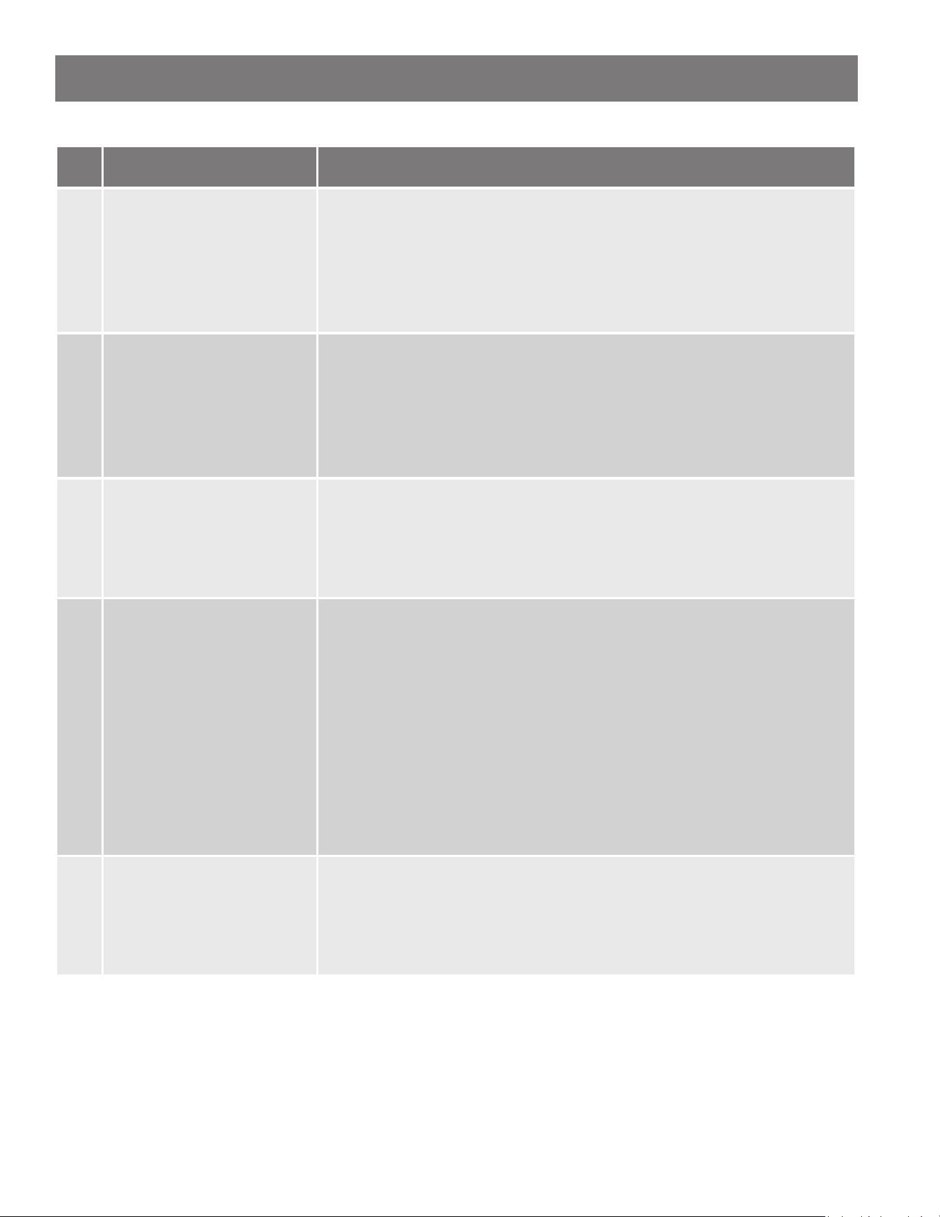
Residenal Non-Condensing Gas Tankless Water Heater Use and Care Guide • 61
TROUBLESHOOTING
Table 24: Error Code Fault Analysis
Error
Code
Error Descripon Procedure
E416 Analog/Digital (AD) Value Fault
1. Check the outlet thermistor sensor wire for a short or disconnecon. Correct
any loose connecons and replace any damaged wire/connector. If the error
sll occurs, contact a qualied service technician.
2. Remove the outlet thermistor (do not lose the O-ring) and check for any dirt or
debris. Clean with an Emery cloth. If the thermistor is damaged, replace it.
3. If the error sll occurs, contact a qualied service technician to replace the PCB.
E419 Flame Signal Lost
1. Check the ame sensor wire for a short or disconnecon. Correct any loose
connecon and replace any damaged wire/connector.
2. With the water heater power disconnected, check the exhaust vent and air
intake piping for any blockages. Remove any blockages. If the error sll occurs,
contact a qualied service technician.
3. If the error sll occurs, contact a qualied service technician.
E427 Flow Control Valve
1. Check the ow control valve wires for a short or disconnecon. Correct any
loose connecons and replace any damaged wire/connector.
2. Remove the ow control valve and inspect for any debris or damage. Replace
if needed. First follow the draining procedure in the Unit Draining & Power
Outage secon in this manual.
E428 Flow Sensor - Cascade Only
1. Verify the water heater’s operaon is enabled. The heater’s UIM will display
the set temperature when enabled. If it is disabled, press the heater’s ON/OFF
buon to enable the heater’s operaon.
2. Verify that the heater’s water shuto valves are open.
3. Check the ow sensor wires for a short or disconnecon. Correct any loose
connecons and replace any damaged wire/connector.
4. Drain the water heater following Unit Draining & Power Outage secon in this
manual.
5. Remove the ow sensor and inspect for any debris or damage. Replace if need-
ed.
6. Remove and clean the inlet water lter.
E429
Flow Control Valve Fault -
Cascade Only
1. Check the ow control valve wires for a short or disconnecon. Correct any
loose connecons and replace any damaged wire/connector.
2. Remove the ow control valve and inspect for any debris or damage. Replace
if needed. First follow the draining procedure in the Unit Draining & Power
Outage secon in this manual.
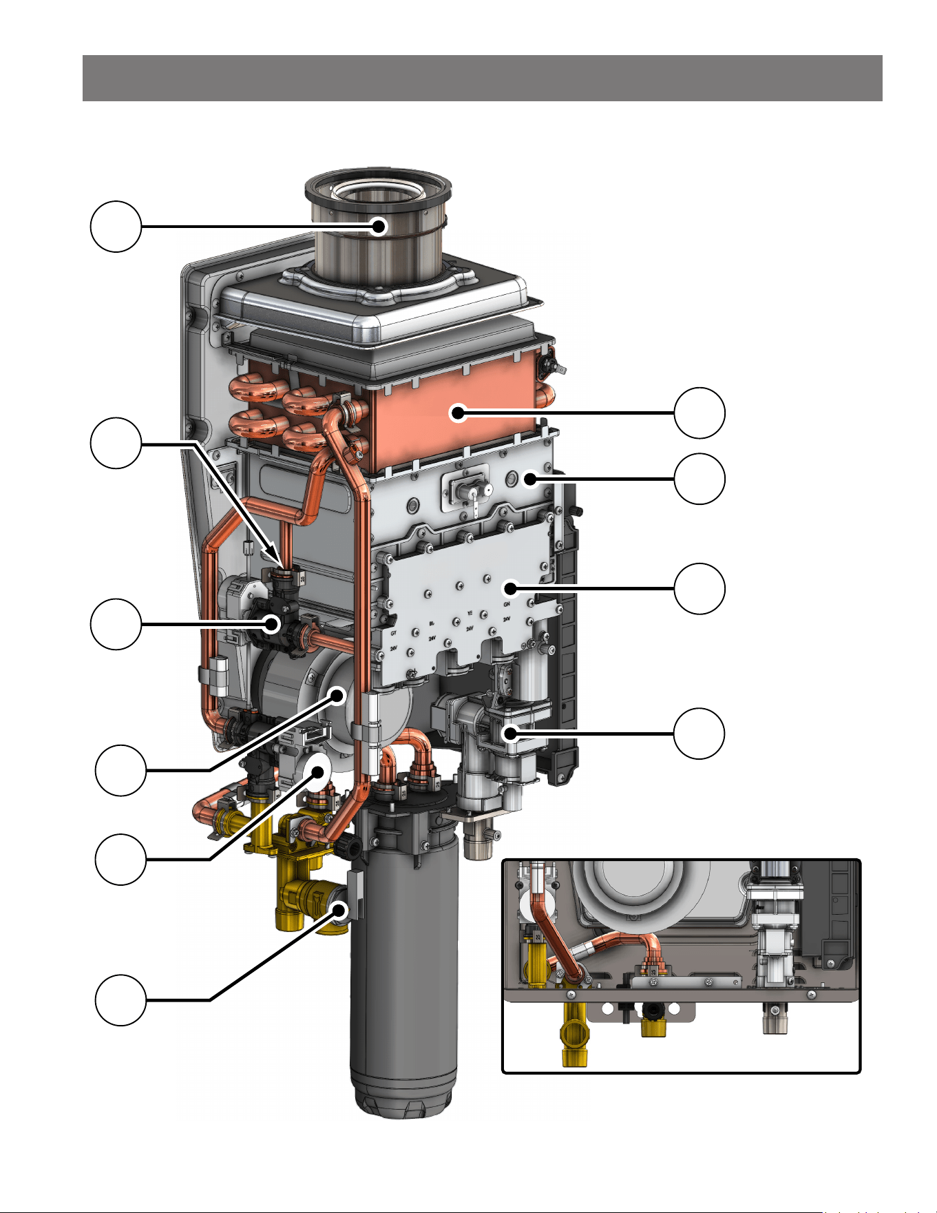
62 • Residenal Non-Condensing Gas Tankless Water Heater Use and Care Guide
Component View (Indoor Model)
2
5
Base (B Model) Configuration
NOTICE: Display removed for clarity.
See Table 25 on page 64 for parts
description list.
6
4
1
3
7
8
9
10
COMPONENTS
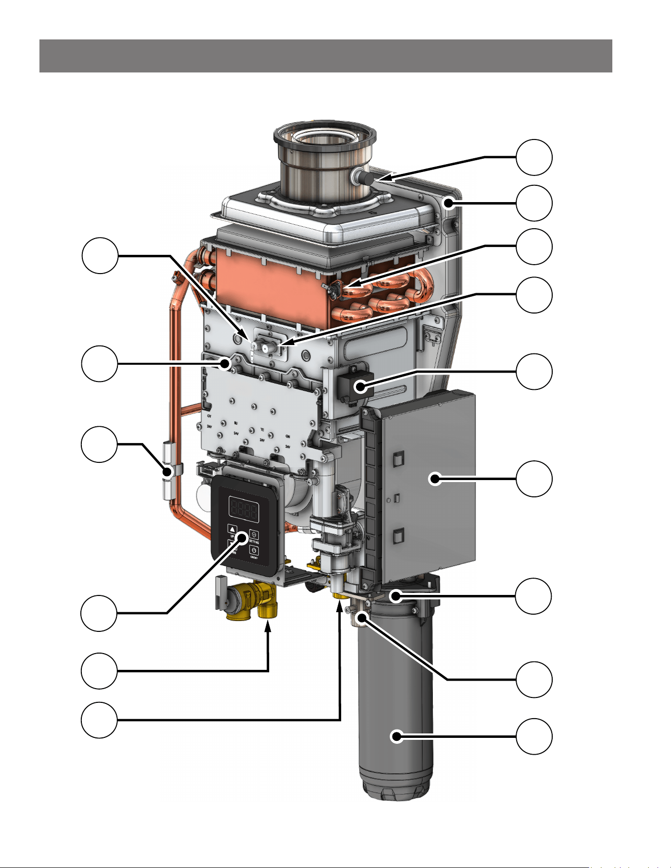
Residenal Non-Condensing Gas Tankless Water Heater Use and Care Guide • 63
Component View (Indoor Model)
20
24
15
16
13
17
14
11
12
18
19
21
23
25
22
COMPONENTS
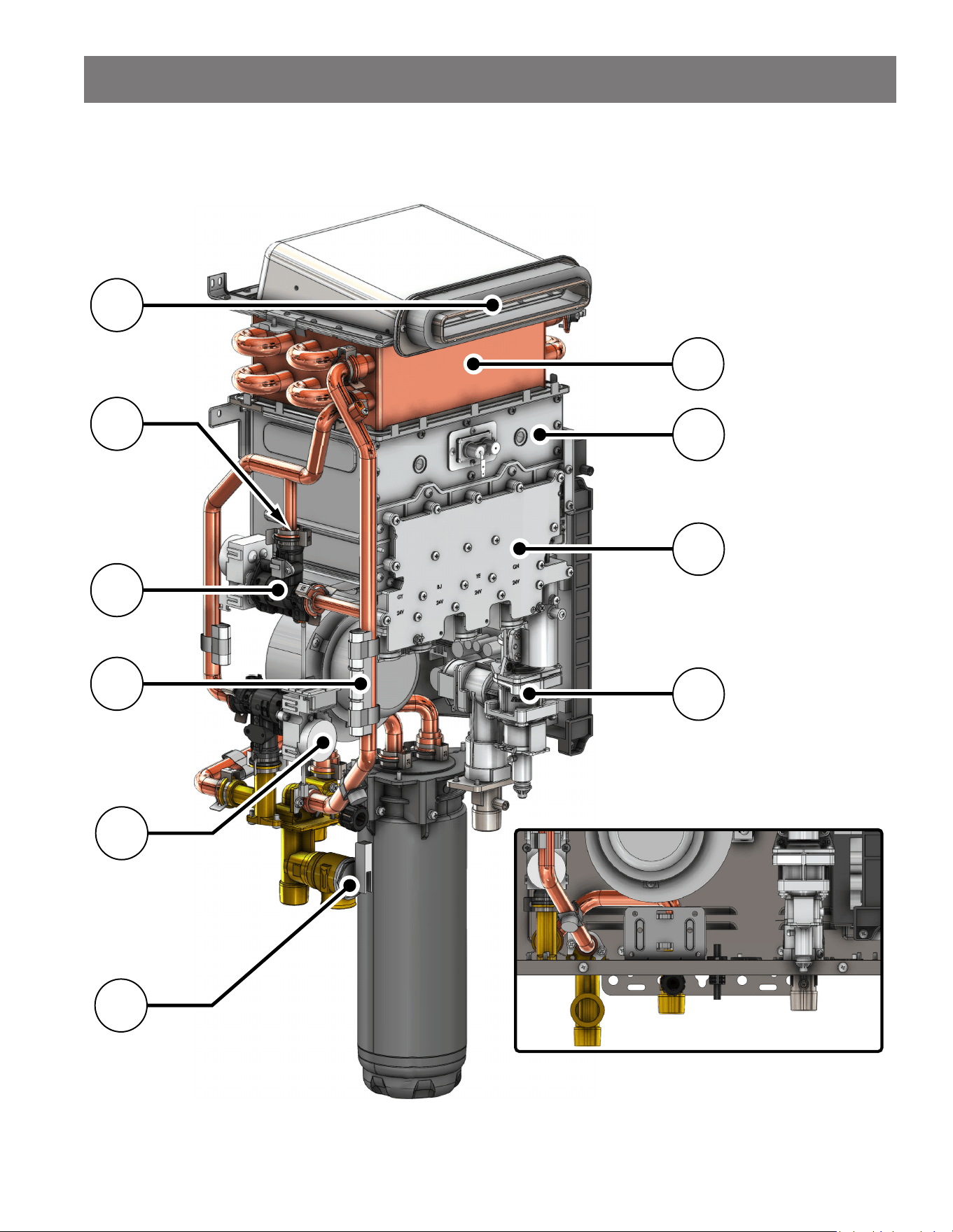
64 • Residenal Non-Condensing Gas Tankless Water Heater Use and Care Guide
COMPONENTS
Component View (Outdoor Model)
Base (B Model) Configuration
2
5
6
1
7
8
9
10
3
4
NOTICE: See Table 26 on page 64
for parts description list.
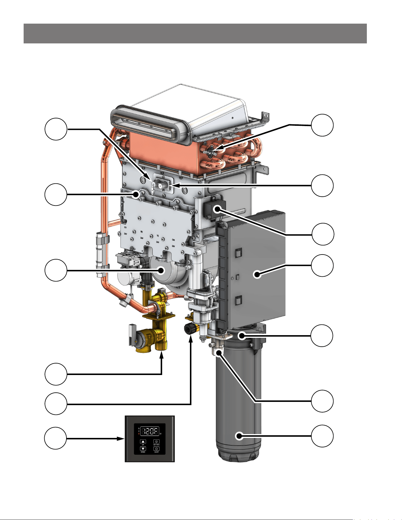
Residenal Non-Condensing Gas Tankless Water Heater Use and Care Guide • 65
COMPONENTS
Component View (Outdoor Model)
17
22
14
15
20
11
19
12
13
16
18
21
23
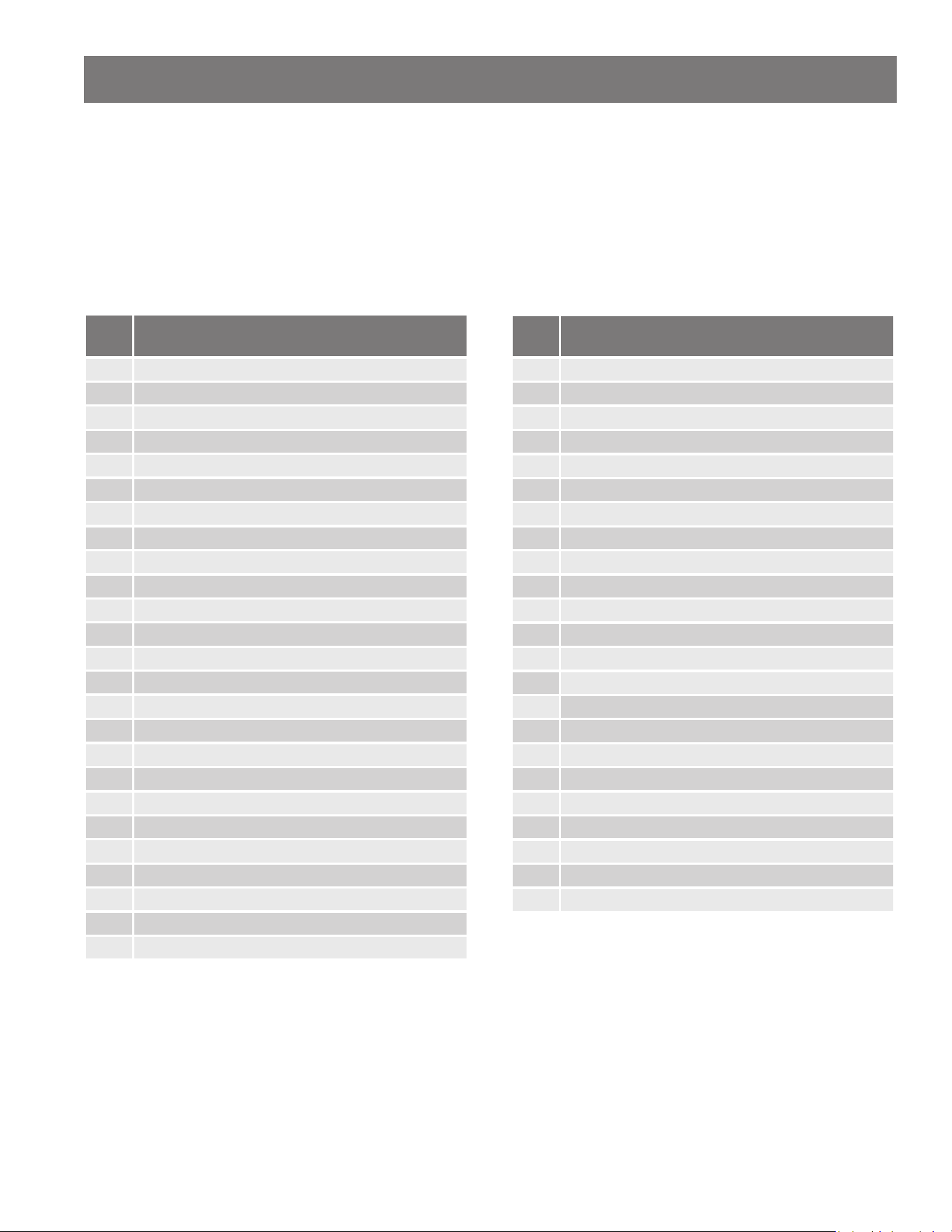
66 • Residenal Non-Condensing Gas Tankless Water Heater Use and Care Guide
Components List
When ordering repair parts, always give the following
informaon:
1. Model, serial, and product number
2. Item number
3. Parts descripon
Table 25: Repair Parts List (TI Indoor Model)
Item
No.
Parts Descripon (Indoor Model)
1 3" Exhaust / 5" Intake Connecon
2 Water Tube Retaining Clip
3 Bypass Water Valve
4 Blower
5 Main Water Valve
6 Pressure Relief Valve
7 Heat Exchanger
8 Burner
9 Gas Manifold Cover
10 Gas Valve
11 Flame Sensor Rod
12 Gas Manifold
13 Freeze Protecon
14 User Interface Module (UIM)
15 Hot Water Outlet
16 Cold Water Inlet
17 Venng Condensate Drain Port
18 Air Intake Plenum
19 Hi-Limit Switch
20 Ignitor Rod
21 Ignitor Assembly
22 Printed Circuit Board (PCB)
23 Cartridge Manifold (X3® shown)
24 3/4" Gas Connecon
25 X3® Cartridge (X3® shown)
Table 26: Repair Parts List (TO Outdoor Model)
Item
No.
Parts Descripon (Outdoor Model)
1 Exhaust
2 Water Tube Retaining Clip
3 Bypass Water Valve
4 Freeze Protecon
5 Main Water Valve
6 Pressure Relief Valve
7 Heat Exchanger
8 Burner
9 Gas Manifold Cover
10 Gas Valve
11 Flame Sensor Rod
12 Gas Manifold
13 Blower
14 Hot Water Outlet
15 Cold Water Inlet
16 Remote Controller
17 Hi-Limit Switch
18 Ignitor Rod
19 Ignitor Assembly
20 Printed Circuit Board (PCB)
21 Cartridge Manifold (X3® shown)
22 3/4" Gas Connecon
23 X3® Cartridge (X3® shown)
COMPONENTS
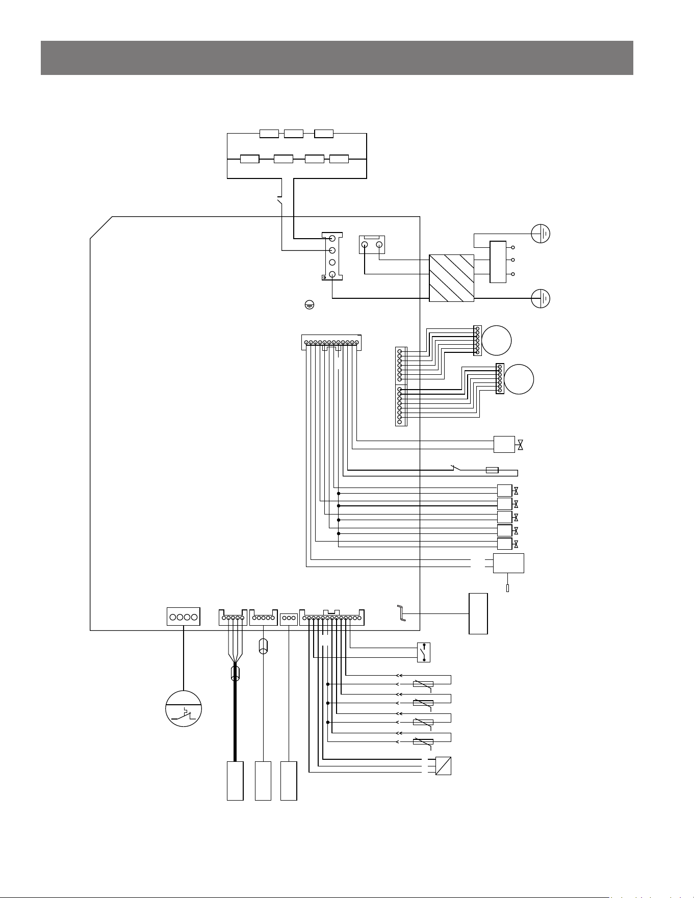
Residenal Non-Condensing Gas Tankless Water Heater Use and Care Guide • 67
Electrical Wiring Diagram
ANTI-FREEZE
ANTI-FREEZE
SWITCH
10W10W10W
10W10W25W25W
120 VAC POWER
L N
CN1
EARTH
CN2
L
N
EARTH
CN0
MAGNETIC
RING
120 VAC
POWER
PE
N
L
CN6
M
MAIN
WATER
VALVE
BYPASS
WATER
VALVE
M
CN7
PROPORTIONAL
VALVE
+
-
1
2
THERMAL FUSEHIGH LIMIT
CON2
MAIN VALVE
VALVE C
VALVE B
VALVE A
VALVE D
24V
IGNITOR
IGNITOR
ROD
INGI
GND
VAL_D
VAL_C
VAL_B
VAL_A
MAIN_V
24V
24V_IN
24V_OUT
P_VAL-
P_VAL+
24V
GROUND
FLAME1
GROUND
GROUND
FLAME
SENSOR
CN5
CASCADE
CN8CN9
CN4
M
FAN
DISPLAY
FERRITE
BEAD
(OR OTHER COMMUNCATION
EQUIPMENT)
RESERVED
FERRITE
BEAD
CON1
LIQUID
LEVEL
SWITCH
INLET WATER
TEMPERATURE
OUTLET WATER
TEMPERATURE
SMOKE
TEMPERATURE
HEAT EXCHANGER
TEMPERATURE
WATER FLOW
SENSOR
1
2
3
5V
5V
(OR OTHER COMMUNCATION
EQUIPMENT)
APPENDIX
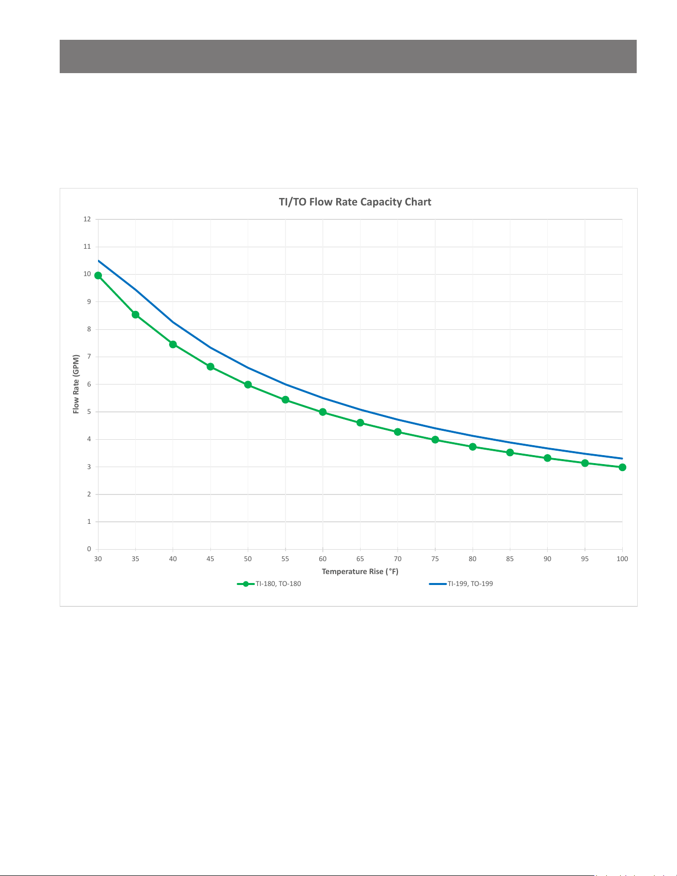
68 • Residenal Non-Condensing Gas Tankless Water Heater Use and Care Guide
Flow Rate Capacity Chart
The chart is based on a properly sized gas line and installaon at 0-2,000 . (0-610 m). The water heater will de-rate
approximately 3% (NG) per 1,000 . (305 m) of elevaon increase above 2,000 . (610 m).
0
1
2
3
4
5
6
7
8
9
10
11
12
30
35
40
45
50
55
60
65
70
75
80
85
90
95
100
Flow Rate (GPM)
Temperature Rise (
°
F)
TI/TO Flow Rate Capacity Chart
TI-180, TO-180
TI-199, TO-199
APPENDIX

Residenal Non-Condensing Gas Tankless Water Heater Use and Care Guide • 69
NOTES

70 • Residenal Non-Condensing Gas Tankless Water Heater Use and Care Guide
NOTES

Residenal Non-Condensing Gas Tankless Water Heater Use and Care Guide • 71
NOTES

Copyright © 2025, A.O. Smith.
All Rights Reserved