Installation, Operation and Maintenance Manual
Part Number 4520899 Rev 2 12/15
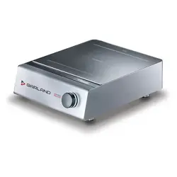
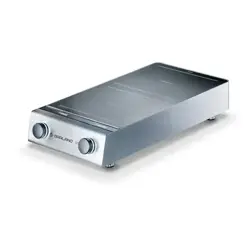
Induction Counter-Top Series
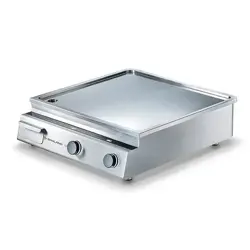
RTCS® Cooktop Line Single Cook Zone
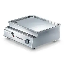
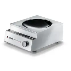
RTCS® Wok Line
models
GI-BH/BA 1500
GI-BH/BA 1800
GI-BH/BA 2500
GI-BH/BA 3000
GI-BH/BA 3500
GI-SH/BA 2500
GI-SH/BA 3500
GI-SH/BA 5000
GI-SH/WO 3500
GI-SH/WO 5000
GI-SH/WO 8000
Original Instructions
READ THIS MANUAL
n
Warning
Read this manual thoroughly before installing,
operating, or performing maintenance on the
equipment. Failure to follow instructions in this manual
can cause property damage, injury or death.
This manual must always be available for reference at
the place of operation.
This manual is intended for kitchen consultants, cabinet
designers, fabricators, installers, owners and operators of
our appliances.
Owners, consultants, fabricators and designers:
In order for the induction appliance to function safely
and normally, you must read and understand all
specific and critical requirements when designing the
location and the counter for the appliance.
Installers, operators and staff:
For your safety and safety of the others, you must
observe all safety instructions during installation,
operation and maintenance of the equipment.
Should you require technical assistance, call your factory
authorized service agent or distributor. Always have your
model and serial number available when you call.
Your Factory Authorized Service Agent
Service Agent Telephone Number
Your Local Equipment Supplier
Supplier Telephone Number
Model Number
Serial Number
Date of Installation
ABOUT THIS MANUAL
Throughout this manual, the induction appliance model
indicated on the cover page is referred to as appliance,
induction appliance or equipment.
A period (.) is used in this manual as the decimal separator.
Original measurements are in metrics. Measurements in
imperial are provided for reference.
Not ALL models, options and accessories are available in all
geographical regions. Please consult your local equipment
supplier for the availability of the specific products in your
region.
INSPECT THE SHIPMENT
Thoroughly inspect the equipment upon delivery.
Immediately report to the delivery carrier, any damage that
occurred during transportation and request for a written
inspection report from a claim inspector.
Your shipment might include small packages of fasteners
or silicone strips for installation. Keep all packages.
KEEP THE PACKING SLIP
The packing slip attached to the shipment contains
detailed information on all components. Keep the packing
slip for reference.
Part Number 4520899 Rev 2 12/15 3
Safety Notices
Safety Notices
DEFINITIONS
DANGER
Indicates a hazardous situation that, if not avoided, will
result in death or serious injury. This applies to the most
extreme situations.
n
Warning
Indicates a hazardous situation that, if not avoided,
could result in death or serious injury.
,
Caution
Indicates a hazardous situation that, if not avoided,
could result in minor or moderate injury.
Notice
Indicates information considered important, and is used
to address practices not related to physical injury. For
example, messages relating to property damage.
NOTE: Indicates useful, extra information about the
procedure you are performing.
Reference: ANZI Z535.6-2011
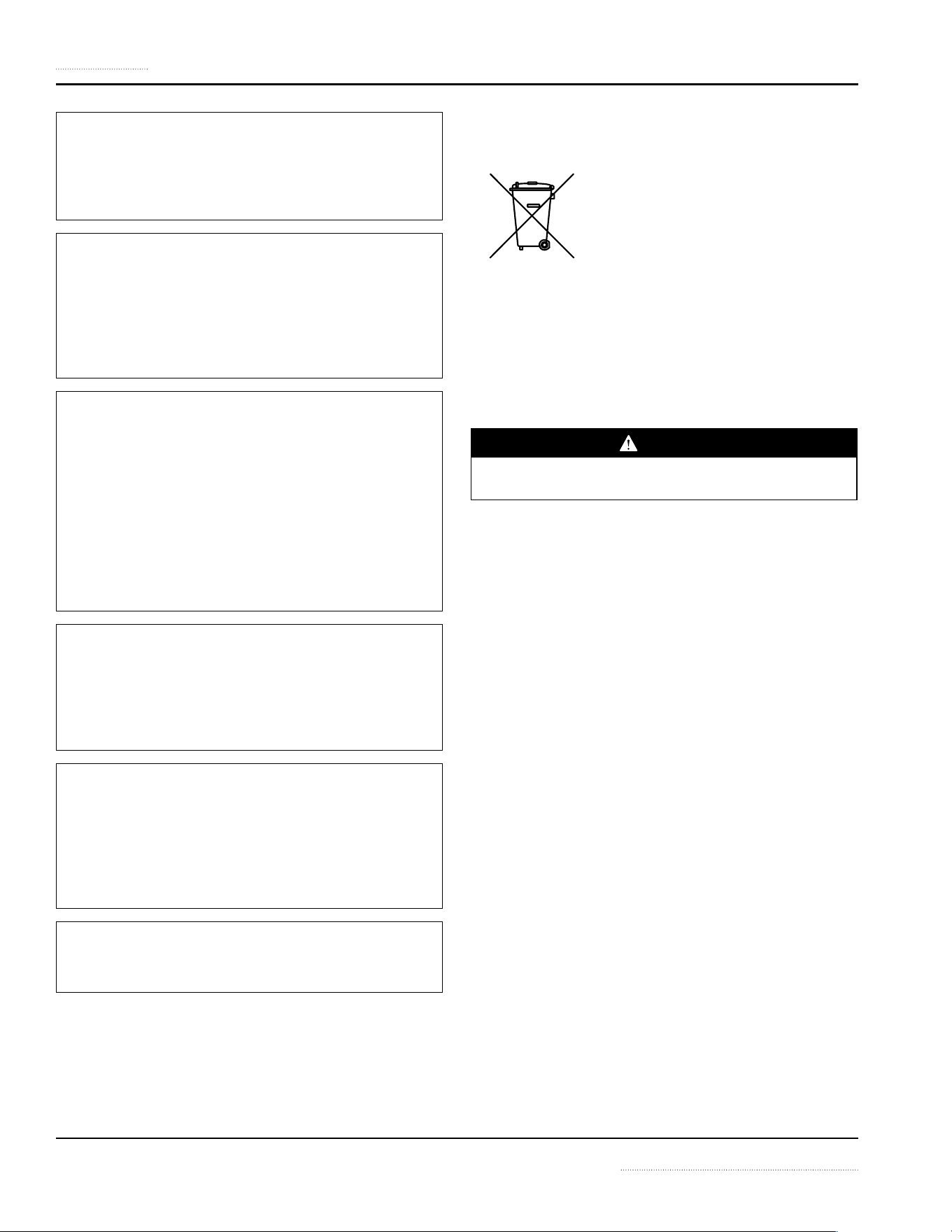
SAFETY SYMBOLS AND WARNINGS ON THE APPLIANCE
This symbol alerts you to a hazardous situation
that WILL or COULD cause serious bodily harm
or death. Be alert and implement relevant safety
precautions.
DANGER - HIGH VOLTAGE
This dangerous voltage warning symbol
indicates a risk of electric shock and hazards
from dangerous voltage.
Electromagnetic Field
Warning
RISK OF FIRE OR ELECTRIC SHOCK! DO NOT OPEN!
To reduce the risk of fire or electric shock, do not remove or
open cover. No user serviceable parts inside.
Refer servicing to qualified personnel.
CAUTION ATTENTION
DISCONNECT FROM SUPPLY CIRCUIT BEFORE OPENING
DISCLAIMERS
DANGER
Disregarding any safety instructions may cause harm to
people, the surroundings, and the equipment. Garland
is not responsible for any damages or personal injury
caused by failure to observe any safety requirements.
Risks involved when disregarding safety precautions
include, but not limiting to:
• Death or injury caused by electric shock.
• Burn injury caused by contacting overheated cooking
surface, cookware, or oil and grease.
• Damage to the equipment caused by using
unsuitable cookware.
DANGER
Do not install or operate equipment and/or accessories
that have been misused, abused, neglected, damaged,
or altered from that of original manufactured
specifications.
DANGER
Contact the manufacturer if you intend to make any
changes on the equipment. For safety reasons, always
use genuine parts and accessories approved by the
manufacturer or authorized representative. Refer to the
warranty documents for your equipment.
DANGER
Owners and operators are cautioned that maintenance
and repairs must be performed by an authorized service
agent using only genuine replacement parts. The
manufacturer will have no obligation with respect to any
product that has been improperly installed, adjusted,
operated or not maintained in accordance with national
and local codes and/or installation instructions provided
with the product or any product that has its serial
number defaced, obliterated or removed, and/or which
has been modified or repaired using unauthorized parts
or by unauthorized service agents.
DANGER
Improper installation, adjustment, alteration, service,
or maintenance of this appliance or installation of
a damaged appliance can result in DEATH, INJURY,
EQUIPMENT DAMAGE, and void the warranty.
DANGER
All utility connections and fixtures must be maintained
in accordance with local and national codes.
4 Part Number 4520899 Rev 2 12/15
Safety Notices
n
Warning
Do not store or use gasoline or other flammable vapors
or liquids in the vicinity of this or any other appliance.
Never use flammable oil soaked cloths or combustible
cleaning solutions for cleaning.
n
Warning
This appliance is not intended for use by persons
(including children) with reduced physical, sensory or
mental capabilities, or lack of experience and knowledge,
unless they have been given supervision concerning
use of the appliance by a person responsible for their
safety. Do not allow children to play with this appliance.
n
Warning
This product contains chemicals known to the State
of California to cause cancer and/or birth defects or
other reproductive harm. Operation, installation, and
servicing of this product could expose you to airborne
particles of glass-wool or ceramic fibers, crystalline
silica, and/or carbon monoxide. Inhalation of airborne
particles of glass-wool or ceramic fibers is known to the
State of California to cause cancer. Inhalation of carbon
monoxide is known to the State of California to cause
birth defects or other reproductive harm.
n
Warning
Authorized Service Representatives are obligated to
follow industry standard safety procedures, including,
but not limited to, local/national regulations for
disconnection / lock out / tag out procedures for all
utilities including electric, gas, water and steam.
Notice
This appliance is not approved or authorized for home
or residential use, but is intended for commercial
applications only. The manufacturer and/or authorized
representative will not provide service, warranty,
maintenance or support of any kind other than in
commercial applications.
Notice
Routine adjustments and maintenance procedures
outlined in this manual are not covered by the warranty.
NOTE: Proper installation, care and maintenance are
essential for maximum performance and trouble-free
operation of your equipment. Visit our website
www.mtwkitchencare.com for manual updates,
translations, or contact information for service agents in
your area.
CORRECT DISPOSAL OF THIS PRODUCT
This marking shown on the product
indicates that the product should not be
disposed as household waste or regular
commercial waste. Instead it shall be
handed over to the applicable collection
point for the recycling of electrical and electronic
equipment. By ensuring this product is disposed correctly,
you will help prevent potential harm to the environment
or human health, which could otherwise be caused by
inappropriate waste handling of this product.
For more detailed information regarding recycling of the
product, please contact your local city office or your waste
disposal service.
DANGER
Induction appliances, sent for disposal, can be brought
back into operation and their use must be avoided.
NOTE: The appliance is built with common electrical,
electromechanical and electronic parts. No batteries are
used.
NOTE: The owner and operator are responsible for the
proper and safe disposal of the appliance.

5
Safety Notices
Definitions.................................................................................................................................................3
Safety symbols and Warnings on the Appliance ........................................................................3
Disclaimers ................................................................................................................................................3
Correct Disposal of This Product .......................................................................................................4
Section 1
General Information
Description of Product .......................................................................................................7
Application .........................................................................................................................7
Compliances .......................................................................................................................7
Components and Features ................................................................................................7
Serial Plate Location ..........................................................................................................8
Model Number ....................................................................................................................8
Serial Number .....................................................................................................................8
Accessories ..........................................................................................................................8
Section 2
Installation
Installation safety—Disclaimer .........................................................................................................9
Installation Safety—Clearance and Ventilation ...........................................................................9
Personal Protection ............................................................................................................................ 10
Installation Safety—Electrical ......................................................................................................... 10
Specifications ...................................................................................................................11
Dimensions: BH/BA 1500, BH/BA 1800, BH/BA 2500, BH/BA 3000, BH/BA 3500 .......... 11
Dimensions: SH/BA 2500, SH/BA 3500, SH/BA 5000 ............................................................... 11
Dimensions: SH/WO 3500, SH/WO 5000, SH/WO 8000 ......................................................... 12
Installation Clearance ........................................................................................................................ 12
Parallel installation and Clearance ................................................................................................ 13
Electrical Specifications..................................................................................................................... 13
Electrical Cables ................................................................................................................................... 14
Operating Conditions ........................................................................................................................ 14
Weights ................................................................................................................................................... 14
Installation Instructions ..................................................................................................15
Location of the Induction Appliance ........................................................................................... 15
Ventilation Requirements.................................................................................................................15
Adjusting and Locking the Feet ..................................................................................................... 15
Commissioning .................................................................................................................................... 16
Function Test .....................................................................................................................16
Table of Contents
Part Number 4520899 Rev 2 12/15

6 Part Number 4520899 Rev 2 12/15
Table of Contents (continued)
Section 3
Operation
Operation Safety—Disclaimer ........................................................................................................17
Operation Safety—Personal Protection ...................................................................................... 17
Important Rules—Operation and Maintenance ............................................................ 19
Proper Induction Cookware ............................................................................................20
Condition ...............................................................................................................................................20
Round bottom Wok pans.................................................................................................................. 20
Material ................................................................................................................................................... 20
BOIL TEST ................................................................................................................................................ 20
Size of Pan .............................................................................................................................................. 21
Placing Pan On A Cook Zone ...........................................................................................21
Power Control ...................................................................................................................22
Power Level Settings .......................................................................................................................... 22
Automatic Pan Detection, No Pan No Heat ....................................................................23
Reading the Signals from An Indicator Lamp ................................................................23
When Appliance Is Idle.....................................................................................................23
Section 4
Maintenance
Maintenance Safety—Disclaimer ..................................................................................................24
Dangerous Electrical Voltage .......................................................................................................... 24
Maintenance Safety—Cleaning ..................................................................................................... 24
Personal Protection ............................................................................................................................ 25
Daily Cleaning and Maintenance ....................................................................................26
Glass Cleaning ...................................................................................................................................... 26
Stainless Steel case ............................................................................................................................. 26
Visual Inspection of Silicone Seal .................................................................................................. 26
Weekly Cleaning and Maintenance ................................................................................26
Air Intake Filter, Countertop Models ............................................................................................ 26
Air Intake Filter, Built-In Models ..................................................................................................... 27
Yearly Maintenance ..........................................................................................................27
Section 5
Troubleshooting
Dangerous Electrical Voltage .......................................................................................................... 28
Common Problems ........................................................................................................... 28
Symptoms .........................................................................................................................28
Boil Test .............................................................................................................................28
Troubleshooting Without Error Code / Flash Code ........................................................ 29
Troubleshooting — Error Code / Flash Code .................................................................. 29
Wearable Parts List ...........................................................................................................31
Part Number 4520899 Rev 2 12/15 7
Description of Product
Built with a robust construction, our induction appliances
are compact and powerful with the revolutionary RTCS®
or RTCSmp® Technology (Realtime Temperature Control
System).
The RTCS®/RTCSmp® Technology monitors continuously in
realtime, the energy supply, temperature of the cook zone,
and the state of the components such as the induction coil.
This monitoring system ensures the most efficient energy
transfer, as well as maximizes safety:
• Safety functions such as Pan Detection and Boil Dry
Protection are therefore guaranteed.
• The appliance generates power only when a pan is in
contact with the cook zone surface.
• When a malfunction occurs, the integrated fault
diagnostic system reports the malfunction instantly.
Application
The RTCS®/RTCSmp® induction appliances are designed as
compact equipment for use on the surface of a counter or
table.
Many applications throughout the day with your appliance
are possible, such as cooking, warming up, keeping warm,
flambéing, and roasting of food. All these applications are
possible because:
• Temperature control is instantaneous and precise.
Instant energy transmission from inverter coil to the
bottom of cookware, allows for fast startup time.
• High power is possible for braising application and
quick sauté.
• High power also means you can heat up a large
stockpot quickly (3.5kW coil or above).
NOTE: To guarantee the reliability and performance of the
appliance, you must use the recommended types and sizes
of pans with the appliance. See section 3 Operation.
Compliances
• North American models:
ETL listed in compliance with UL 197, CSA C22.2
No.109, NSF-4. Complies with FCC part 18, ICES-001
• CE models comply with the latest European Norms:
EN 60335-1, EN 60335-2-36, EN 62233 (EMC/EMV)
Components and Features
Your induction appliance comes fully assembled.
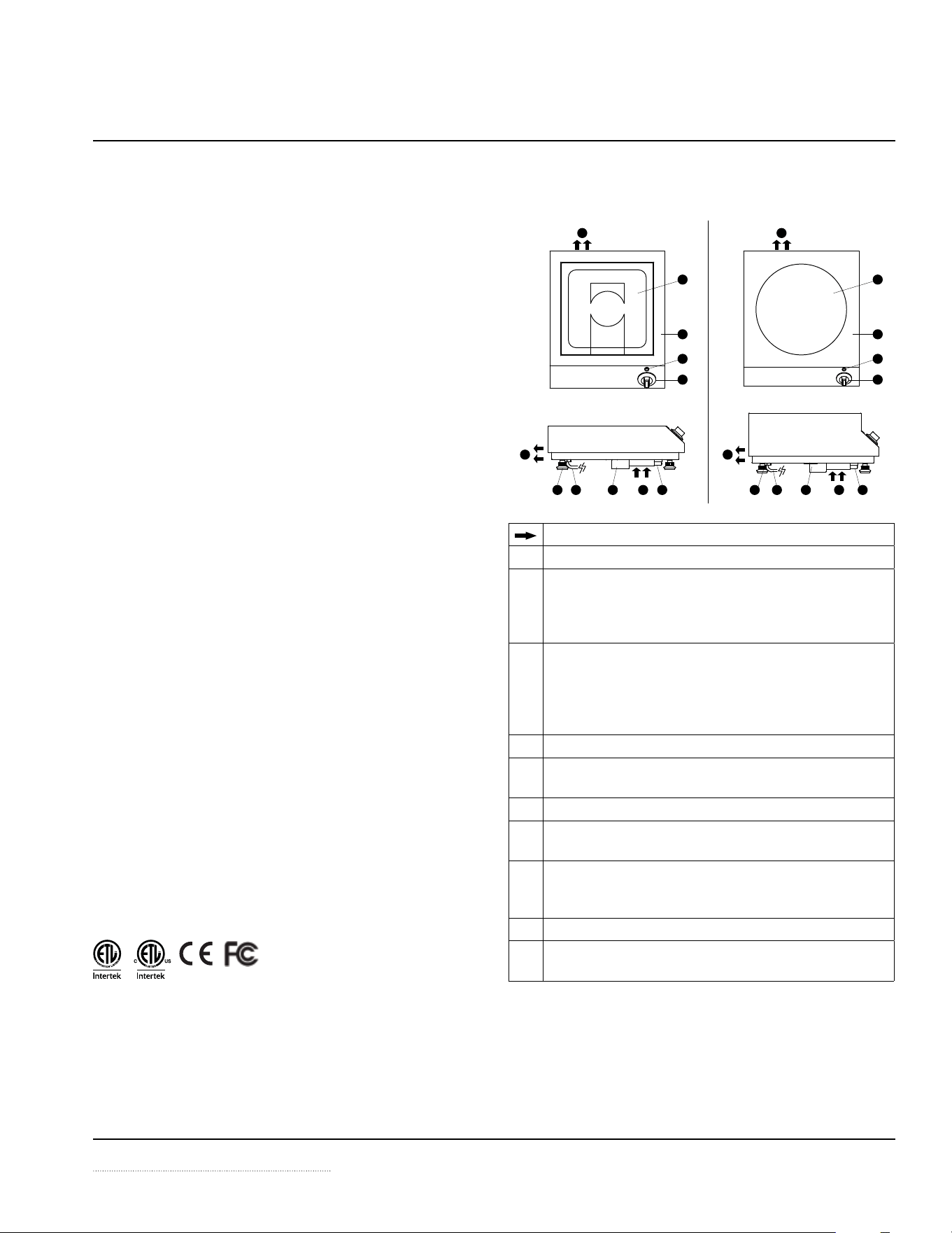
1
1
2
4
3
2
3
4
5
5
6
6
6
6
7
7
8
8
9
9
10
10
Indicates the direction of airflow.
1 Ceran® Glass Cooktop or Wok Bowl, single cook zone
2 Rotary power switch, allows for continuously variable
power adjustment. Dial is marked 0 to 12 power levels. BH
models: dial is marked 0 to 9 power levels.
The front control panel is sloped for ease of operation.
3 Indicator lamp
• Illuminates when the appliance is ON.
• Blinks when the appliance is in Pan Detection Mode.
• Blinks at intervals when a malfunction occurs.
Details in sections 3 Operation and 5 Troubleshooting.
4 CrNi-steel exterior structure.
5 Fresh air intake. An internal fan pulls air in through the
filter to cool the electronics.
6 Air exhaust vent, allows hot exhaust to escape.
7 Air filter, cleans the intake air. The filter is removable,
reusable and dishwasher-safe.
8 Air deflector, prevents hot exhaust from the rear to be
pulled back into the appliance through the air intake
opening.
9 Feet that are height adjustable and lockable.
10 Mains power cable and plug included, 1.8-meter [6-foot]
long (exception 440V appliance).
Section 1
General Information
8 Part Number 4520899 Rev 2 12/15
General Information Section 1
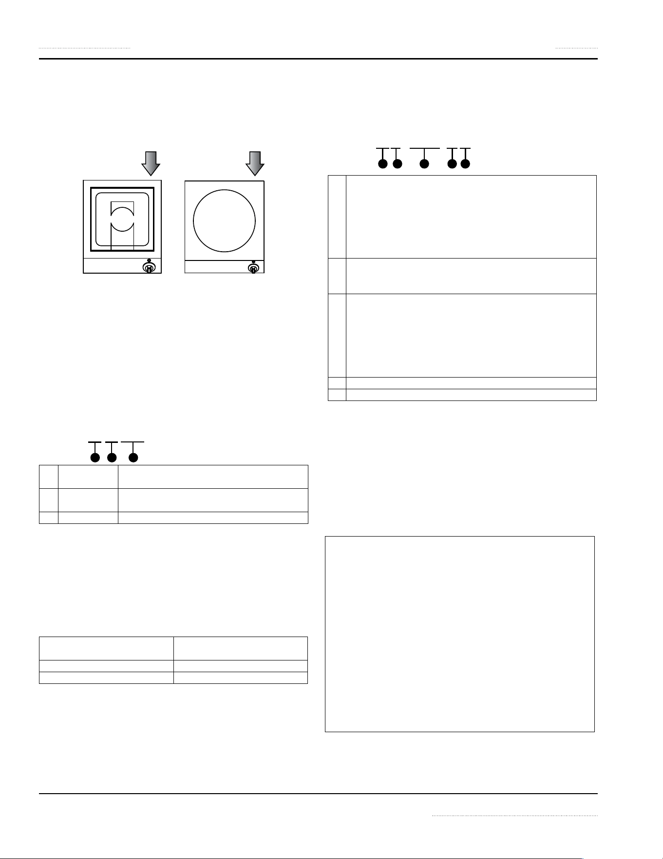
Serial Plate Location
The serial plate specifies the model number, serial number,
and electrical specifications of the appliance.
See illustration below for location.
Model Number
The model number is located on the serial plate. This manual
covers the following models:
BH/BA 1500 SH/BA 2500 SH/WO 3500
BH/BA 1800 SH/BA 3500 SH/WO 5000
BH/BA 2500 SH/BA 5000 SH/WO 8000
BH/BA 3000
BH/BA 3500
READING THE MODEL NUMBER
Example:
BH/BA 2500
3
2
1
1 Product
Series
BH = Baby Hob
SH = Slim Hob
2 Function BA = Base Line Cook-Top
WO = Wok Line
3 Power (Watt) 1500, 1800, 2500, 3000, 3500, 5000, 8000
MARKETING IDENTIFIER
Marketing identifier is used when specifying the product
on specification sheet and other marketing literature. This
product is identified as:
GI-(model number)
Examples:
Marketing Identifier Corresponding Model
Number on Serial Plate
GI-SH/BA 2500 SH/BA 2500
GI-SH/WO 5000 SH/WO 5000
Serial Number
Accessories
Induction cooking equipment requires Induction Ready
pans to operate. Please consult your equipment supplier for
a list of our pan selection and prices.
Notice —Wok Equipment
Use Wok Pans with Correct Contour
The wok pans used must be the correct contour to the
Ceran® glass wok bowl. To reduce premature failures
such as overheating, wok pans should not touch the
glass but only sit on the upper flange.
To guarantee the correct contour, we offer a selection
of induction wok pans. Please consult your equipment
supplier for details.
The serial number is located on the serial plate.
READING THE SERIAL NUMBER
Example:
BA01 . 00014 . 1214
3 4 5
2
1
1 Type of induction appliance:
BA = Base Line Series (Counter-Top Cook-Top)
IN = Built-In Series
WO = Counter Wok Series
MO = Module Line Series
HO = Hold Line Series
GR = Griddle Line Series
2 Last two(2) or three(3) digits of the appliance article number
or part number that can be found on the invoice or the
packing slip.
3 A sequential number:
• A 4-digit sequence number indicates that the
appliance is not RTCS® nor RTCSmp®.
• A 5-digit sequence number indicates that the
appliance is either a RTCS® or RTCSmp® appliance.
• A RTCSmp® appliance is marked as such on the serial
plate.
4 Month of manufacture: 01, 02, 03, 04, ...
5 Year of manufacture: 2014 (14), 2015 (15), ...
Part Number 4520899 Rev 2 12/15 9
Section 2
Installation
INSTALLATION SAFETY—DISCLAIMER
DANGER
Installation must be carried out by registered installation
contractors only.
The contractors are responsible for interpreting all
instructions correctly and performing the installation
in compliance with all applicable national and local
regulations.
The warning signs and serial plates on the equipment
must strictly be followed.
n
Warning
This equipment is intended for indoor use only. Do not
install or operate this equipment in outdoor areas.
n
Warning
To avoid instability, the installation area must be capable
of supporting the combined weight of the equipment
and food product. The equipment must be level side to
side and front to back.
,
Caution
Consultants, fabricators and designers must consult their
counter-top suppliers when designing an appropriate
support structure and clearance for the counter-top and
the installation.
Notice
Induction equipment that is not installed correctly will
have warranty voided.
INSTALLATION SAFETY—CLEARANCE AND
VENTILATION
DANGER
Risk of Fire or Shock or Equipment Failure
All minimum clearances must be maintained. Air intake
vents and exhaust vents must not be blocked or be
restricted by the installation.
,
Caution
This equipment must only be operated under an
approved ventilation system in accordance with all
applicable national and local regulations. Exceptions
may apply.
Notice
The maximum ambient temperature for the
induction appliance to operate must not exceed
40°C [104°F].
Failure to provide adequate ventilation will cause
the appliance to overheat, to reduce power, or to
shutdown.
NOTE: Always maintain enough space between and
around the equipment for maintenance and service.
10 Part Number 4520899 Rev 2 12/15
Installation Section 2
INSTALLATION SAFETY—ELECTRICAL
DANGER
All electrical connections must be carried out by a
certified electrical contractor, who is responsible for
the correct rating and installation of the appliance. The
contractor has to comply with all legal safety regulations
and all applicable national and local electrical codes.
n
Warning
Markings and warning labels mounted directly on the
equipment must be observed at all times and kept in a
fully legible condition.
n
Warning
This equipment must be positioned so that the plug is
accessible unless other means for disconnection from
the power supply, such as circuit breaker or disconnect
switch, is provided.
n
Warning
CE Induction Appliance only: If ground fault current
protective switches are used, they must be provided
with selective activation and designed for a minimum
fault current of 30mA.
Notice
Ensure the supply voltage and the line current match
the specifications given on the serial plate affixed to the
appliance. Wrong voltage will damage the appliance. A
stable power supply must be provided.
Notice
Always refer to the serial plate on the appliance to verify
the electrical data. When the data listed on the serial
plate is different than that listed in this manual, contact
the manufacturer or the authorized representative.
Notice
All cables must be routed, protected and tension free.
PERSONAL PROTECTION
DANGER
All utilities (gas, electric, water and steam) must be
OFF to all equipment and locked out of operation
according to national/regional, as well as company
approved practices during installation, maintenance
and servicing. Always allow appliance to cool.
DANGER
Use appropriate safety equipment during installation,
maintenance and servicing.
DANGER
Never stand, sit, or lean on the equipment! They are
not designed to hold the weight of an adult, and may
collapse or tip if misused in this manner.
DANGER
To avoid cardiac pacemaker malfunction, consult your
physician or pacemaker manufacture about effects of
electromagnetic field on your pacemaker.
n
Warning
Markings and warning labels mounted directly on the
equipment must be observed at all times and kept in a
fully legible condition.
n
Warning
Risk of burns from high temperatures. You may get burnt
if you touch any of the parts during operation. Surfaces
close to the cooking area including side panels may get
hot enough to burn skin. Use extreme caution to avoid
coming in contact with hot surfaces or hot grease. Wear
personal protective equipment.
,
Caution
Use caution when handling metal surface edges of all
equipment.
Part Number 4520899 Rev 2 12/15 11
Section 2 Installation
Specifications
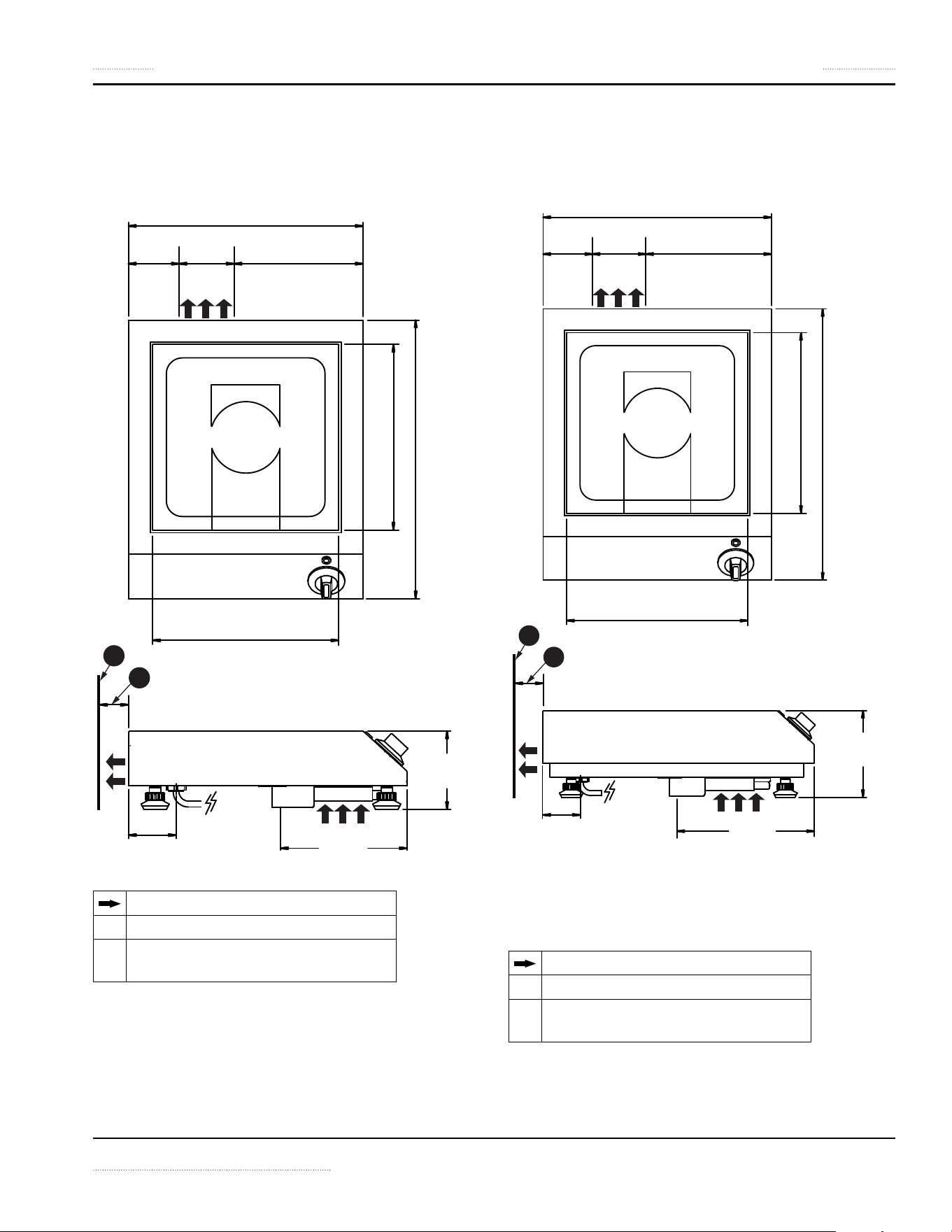
DIMENSIONS: BH/BA 1500, BH/BA 1800, BH/BA 2500,
BH/BA 3000, BH/BA 3500
320mm (12.6")
69mm
(2.7")
75mm
(3.0")
176mm
(6.9")
260mm (10.2")
260mm (10.2")
380mm (15.0")
65mm
(2.5")
173mm
(6.8")
107mm
(4.2")
1
2
Indicates the direction of airflow
1
Wall
2
Distance to wall or other obstruction,
minimum = 40mm [1.57”]
DIMENSIONS: SH/BA 2500, SH/BA 3500, SH/BA 5000
380mm (15.0")
85mm
(3.3")
75mm
(3.0")
220mm
(8.7")
320mm (12.6")
320mm (12.6")
440mm (17.3")
61.5mm
(2.4")
224mm
(8.8")
140mm
(5.5")
1
2
Indicates the direction of airflow
1
Wall or other obstruction
2
Distance to wall or other obstruction,
minimum = 40mm [1.57”]
12 Part Number 4520899 Rev 2 12/15
Installation Section 2
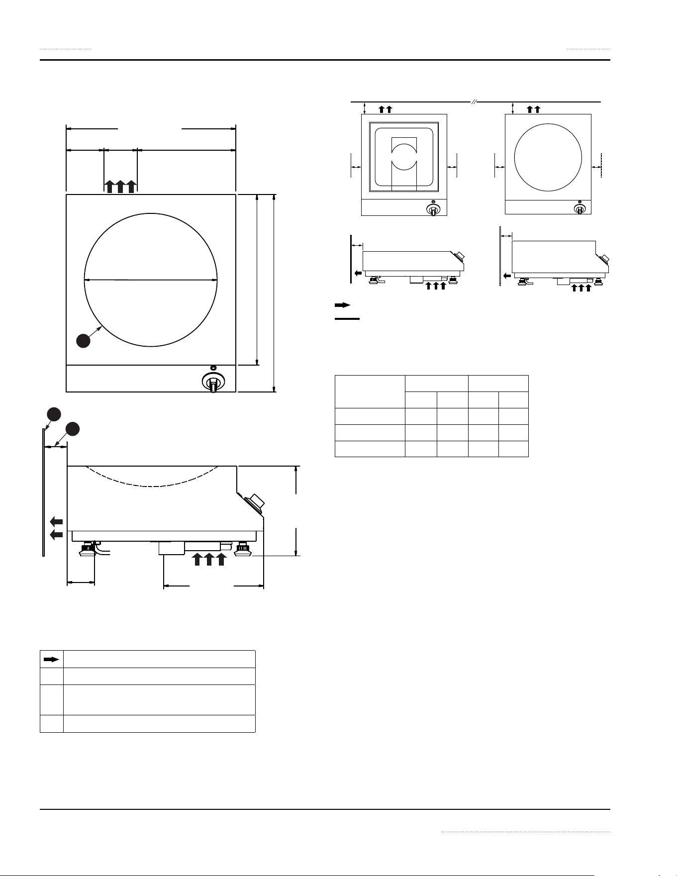
DIMENSIONS: SH/WO 3500, SH/WO 5000, SH/WO 8000
Ø 300mm (11.8")
1
2
380mm (15.0")
200mm
(7.9")
224mm
(8.8")
61.5mm
(2.4")
85mm
(3.3")
75mm
(3.0")
220mm
(8.7")
380mm (15.0")
440mm (17.3")
3
Indicates the direction of airflow
1
Wall or other obstruction
2
Distance to wall or other obstruction,
minimum = 40mm [1.57”]
3
Ceran® glass wok bowl
INSTALLATION CLEARANCE
a
a
b b
a
b b
a
Indicates the direction of airflow.
Wall
Dimension a — minimum clearance, air exhaust
Dimension b — minimum body clearance, sides
Model a b
mm inch mm inch
BH/BA 40 1.57 20 0.79
SH/BA 40 1.57 20 0.79
SH/WO 40 1.57 20 0.79
Part Number 4520899 Rev 2 12/15 13
Section 2 Installation
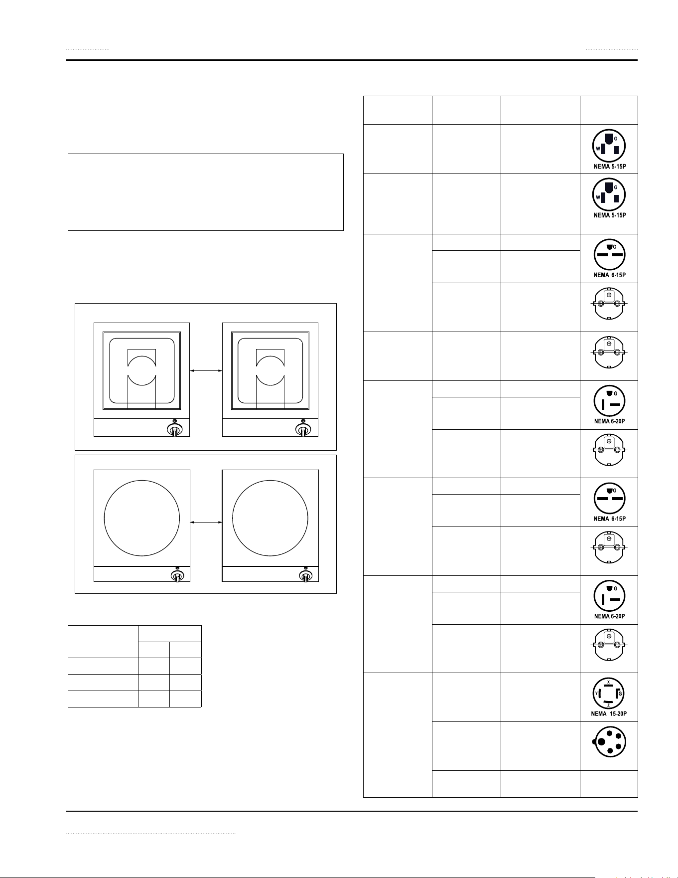
PARALLEL INSTALLATION AND CLEARANCE
When installing multiple appliances on the same counter,
a minimum gap between two appliances must be
maintained. This gap prevents electrical interference and
ensures proper air ventilation.
Notice
The orientation of each appliance in a parallel
configuration will affect the ventilation requirements.
Ensure the final installation meets all operating and
ventilation requirements.
NOTE: Consideration for Operation. Consider the sizes of
typical frying or wok pans and include adequate space in
between equipment for ease of operation.
y
y
Dimension y — minimum gap
Model y
mm inch
BH/BA 200 7.87
SH/BA 200 7.87
SH/WO 200 7.87
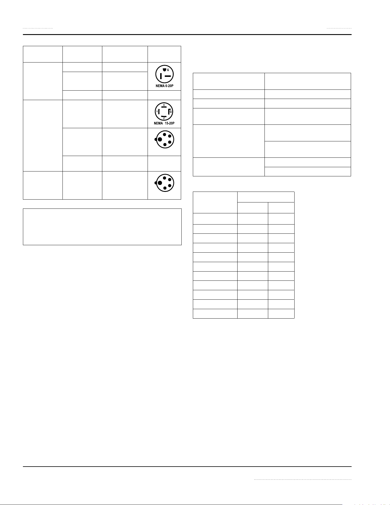
ELECTRICAL SPECIFICATIONS
Model Power Voltage
(50/60 Hz)
Plug
BH/BA 1500 1500W 12A 120V 1Φ
BH/BA 1800 1800W 15A 120V 1Φ
(For USA only)
BH/BA 2500 2500W 13A 208V 1Φ
2500W 11A 240V 1Φ
2500W 12A 230V 1Φ
EU1-16P
BH/BA 3000 3000W 14A 230V 1Φ
EU1-16P
BH/BA 3500 3500W 16A 208V 1Φ
3500W 14A 240V 1Φ
3500W 15A 230V 1Φ
EU1-16P
SH/BA 2500 2500W 12A 208V 1Φ
2500W 11A 240V 1Φ
2500W 12A 230V 1Φ
EU1-16P
SH/BA 3500 3500W 16A 208V 1Φ
3500W 14A 240V 1Φ
3500W 15A 230V 1Φ
EU1-16P
SH/BA 5000 5000W 14A 208V 3Φ
L
5000W 8A 400V 3Φ
EU 5-Pole
5000W 7A 440V 3Φ
Plug not
included
14 Part Number 4520899 Rev 2 12/15
Installation Section 2
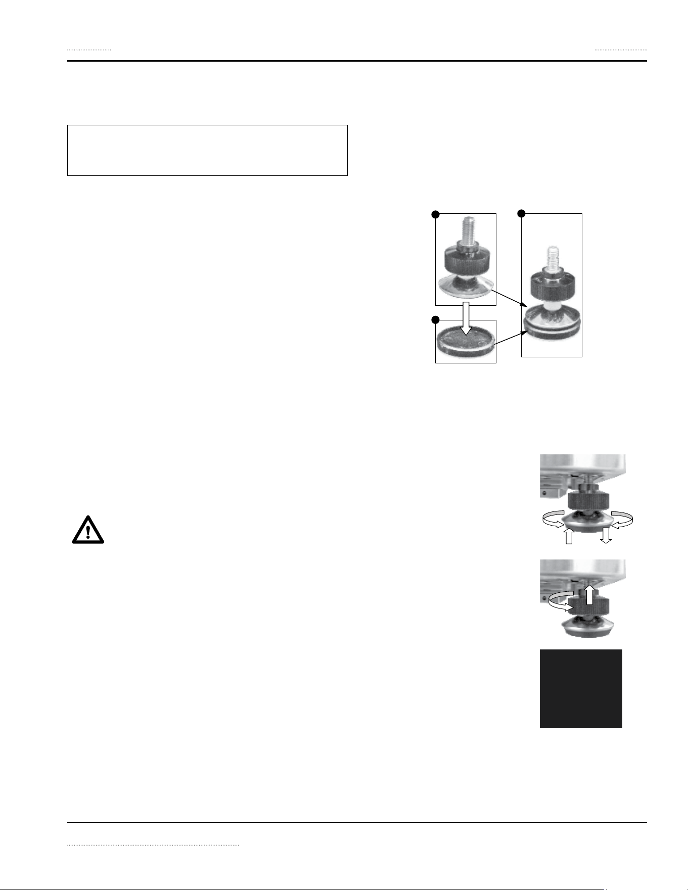
Model Power Voltage
(50/60 Hz)
Plug
SH/WO 3500 3500W 16A 208V 1Φ
3500W 14A 240V 1Φ
3500W 15A 230V 1Φ
SH/WO 5000 5000W 14A 208V 3Φ
L
5000W 8A 400V 3Φ
EU 5-Pole
5000W 7A 440V 3Φ
Plug not
included
SH/WO 8000 8000W 12A 400V 3Φ
EU 5-Pole
Notice
440V Appliance: The electrician must equip the
appliance with a main power plug in compliance with
all applicable national and local regulations.
ELECTRICAL CABLES
Mains power cable and plug included, 1.8-meter [6-foot]
long (exception 440V appliance).
OPERATING CONDITIONS
For the appliance to function properly, the following
conditions must be maintained.
Maximum Tolerance of the
Nominal Supply Voltage
+6 /-10 %
Supply frequency 50/60 Hz
Ingress Protection class IP X3
Minimal Diameter of
Induction Pan
12cm [5”]
Maximum Ambient
Temperature
In Storage,
-20°C to +70°C [-4°F to +158°F]
In Operation,
+5°C to +40°C [+41°F to +104°F]
Maximum Relative Air
Humidity
In Storage, 10% to 90%
In Operation, 30% to 90%
WEIGHTS
Model Net Weight
kg lb
BH/BA 1500 9 19.84
BH/BA 1800 9 19.84
BH/BA 2500 9 19.84
BH/BA 3000 9 19.84
BH/BA 3500 9 19.84
SH/BA 2500 10 22.05
SH/BA 3500 10 22.05
SH/BA 5000 12 26.46
SH/WO 3500 12 26.46
SH/WO 5000 13 28.66
SH/WO 8000 13 28.66
Part Number 4520899 Rev 2 12/15 15
Section 2 Installation
Installation Instructions
LOCATION OF THE INDUCTION APPLIANCE
,
Caution
Do not position the air intake vent near steam or heat
exhaust of another appliance.
• The induction appliance must be installed on an even,
flat, non-combustible surface.
• The surface must be able to hold a load of 40kg [88.2lb]
per appliance that is listed in this manual.
• Ensure the induction appliance is stable and will not
slide or fall down.
• The induction appliance must not be installed or placed
near or on a hot surface.
• The induction appliance must be level.
• Similar to other electronic equipment, induction
equipment is sensitive to moisture and high heat.
Protect the induction appliance from heat, steam and
grease generated by other equipment, such as oven,
deep fryer, pasta cooker, steamers, and water bath.
• The controls on the front panel must not be blocked or
obstructed.
• Keep the induction appliance away from combustible
materials, vapors or liquids.
VENTILATION REQUIREMENTS
Read and understand all installation safety
instructions regarding Clearance and Ventilation
at the beginning of this chapter.
• See also “Operating Conditions” on page 14
• See also “Installation Clearance” on page 12
• Ensure the induction appliance does not take in hot
ambient air or steam from another appliance, especially
when the appliance is installed next to heat generating
equipment such as fryers or ovens.
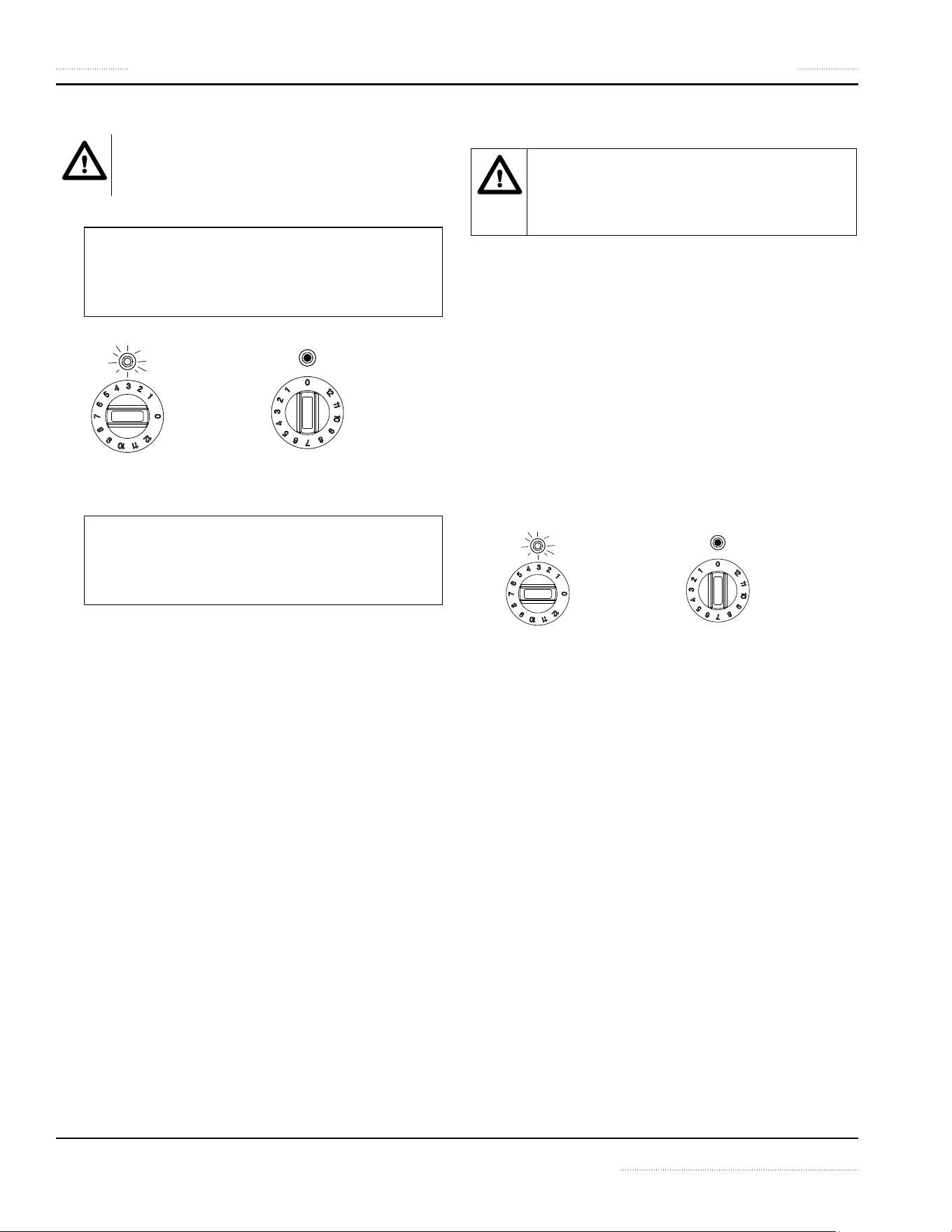
ADJUSTING AND LOCKING THE FEET
The feet on the appliance are height-adjustable and
lockable.
Optional. To prevent the appliance from slipping, Tabletop
Self-Adhesive Foot Pads can be purchased for the feet.
Insert the feet into the Foot Pads and the feet can then be
affixed to the surface of the counter or table.
1
2
3
1. Foot Complete Assembly, part number 95000120
2. Tabletop Self-Adhesive Foot Pad, part number 72264020 (set of
four).
3. Foot and non-slip pad assembled.
To adjust the height of the appliance:
1. Rotate the feet counter-
clockwise to lower the
appliance. Or rotate the
feet clockwise to raise the
appliance.
2. To lock the feet into
position, rotate the locks
counter-clockwise until
the locks are tightened
against the bottom of the
appliance.
3. The feet are locked.
NOTE Ensure the appliance
is level.
16 Part Number 4520899 Rev 2 12/15
Installation Section 2
• Read and understand all installation safety
instructions regarding Personal Protection.
• Observe also ALL operation safety
requirements in section 3 Operation.
Testing procedure:
1. Examine the cookware for induction cooking:
• Pans must be induction ready. See details in
section 3 Operation.
• Minimum pan size: Pan must have bottom
diameter larger than 12cm [5”]. Otherwise, the
pan will not be heated. This is a safety feature.
The sensors do not detect pan smaller than this
minimum size.
2. Put some water in an induction pan and place it in the
center of the cook-zone.
3. Turn the control knob to a ON-position. The indicator
lamp illuminates and the water is heated.
ON-Position
Any position
other than “0”
is pointing to
the Indicator
lamp. The lamp
is on.
OFF-Position
“0” is pointing
to the
Indicator
lamp. The
lamp is off.
4. Remove the pan away from the cook-zone.
NOTE: When power transmission to the pan bottom
stops, the indicator lamp blinks.
5. Place the pan back on the cook-zone. The heating
process resumes.
NOTE: The indicator lamp illuminates continuously
again when energy is being transferred to the pan.
6. Turn the control knob to the OFF/“0”-position. The
heating process stops; the indicator lamp goes off.
If the appliance does not function as expected despite
using quality induction pans, refer to section 5
Troubleshooting.
To test the efficiency of a pan for induction cooking, refer to
section 5 Troubleshooting.
COMMISSIONING
Read and understand all installation safety
instructions regarding Electrical and Personal
Protection.
1.
n
Warning
Ensure the control knobs are in the 0 (OFF) position
BEFORE connecting the appliance to the electrical
supply.
ON-Position
Any position
other
than “0” is
pointing to
the indicator
lamp. The
lamp is on.
OFF-Position
“0” is pointing
to the
indicator
lamp. The
lamp is off.
2. Remove all objects from the glass-top and examine the
glass.
,
Caution
Do not continue if the glass-top is cracked, chipped
or damaged in any other way. Contact an authorized
service agency for assistance.
3. Connect the appliance to power supply.
4. Perform an operation test. See instructions in “Function
Test” on page 16
Function Test
Part Number 4520899 Rev 2 12/15 17
OPERATION SAFETY—DISCLAIMER
DANGER
The on-site supervisor is responsible for ensuring that
operators are made aware of the inherent dangers of
operating this equipment.
DANGER
Risk of fire/shock/equipment failure. All minimum
clearances must be maintained. Do not obstruct
vents or openings.
n
Warning
This equipment is intended for indoor use only. Do not
install or operate this equipment in outdoor areas.
Notice
The reliability of the appliance can only be guaranteed
when it is used properly. The appliance must always
be operated within the limits and/or the operating
conditions provided in this manual.
Notice
Avoid dropping any hard objects onto the equipment.
Damages to the heating surface will shortened the life
cycle of the equipment or incur high service costs.
Notice —Models with Glass-Top
Use Only Induction Suitable Cookware
Use only induction suitable cookware with proper sizes
and made of proper material. The induction suitable
cookware must be in good condition without any
uneven, arched or partially detached bottoms.
Using unsuitable cookware can cause the appliance
to fail prematurely, void your warranty, or incur high
service costs.
Notice —Induction Griddles / Braising Pans
NEVER heat any cooking pan on the griddle plate or
in the braising pan. Heating cooking pan with these
equipment will damage these equipment. Heat only
food products on the griddle plate or in the braising pan.
OPERATION SAFETY—PERSONAL PROTECTION
Notice
Induction appliances are more powerful, heat up
pans quicker, and cook food faster than conventional
cooking equipment. Your induction appliance will
require different use and care than other conventional
equipment.
Do not operate the equipment without reading this
manual and understanding all safety requirements.
DANGER
If any part of the appliance is cracked or broken, Stop
and Immediately Turn Off the appliance. Only if it
is possible and safe, disconnect the equipment from
main power supply. Do not touch any parts inside the
appliance.
Disconnect electric power at the main power disconnect
for all equipment being serviced.
Failure to disconnect the power at the main power
supply disconnect could result in serious injury or death.
The power switch DOES NOT disconnect all incoming
power.
Contact an authorized service agency for assistance.
DANGER
Do not operate any appliance with a damaged or
pinched cord or a damaged plug. All repairs must be
performed by a qualified service company.
DANGER
Keep power cord AWAY from HEATED surfaces. DO NOT
immerse power cord or plug in water. DO NOT let power
cord hang over edge of table or counter.
DANGER
To avoid cardiac pacemaker malfunction, consult your
physician or pacemaker manufacture about effects of
electromagnetic field on your pacemaker.
DANGER
Never stand, site, or lean on the equipment! They are
not designed to hold the weight of an adult, and may
collapse or tip if misused in this manner.
Section 3
Operation

18 Part Number 4520899 Rev 2 12/15
Operation Section 3
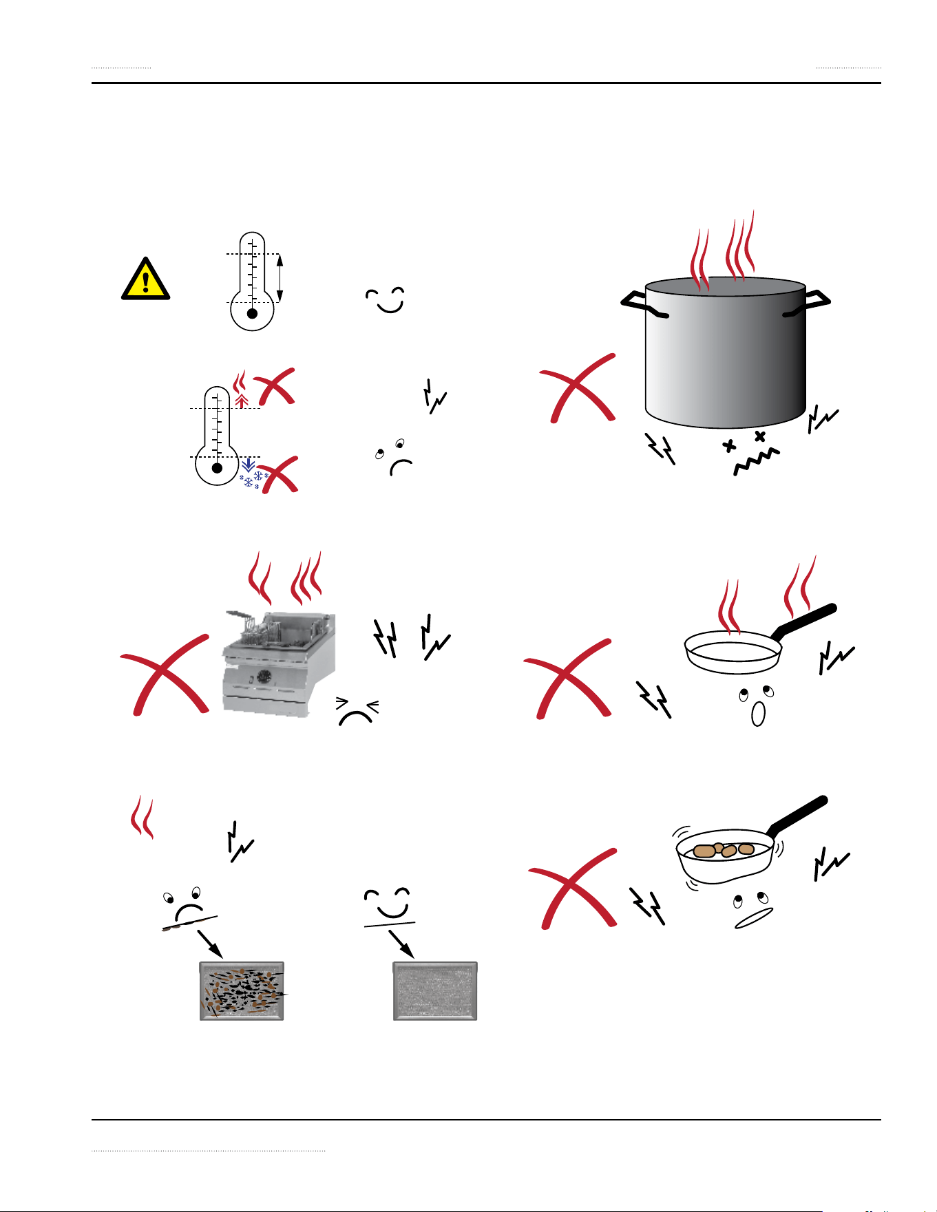
n
Warning
Short Cook Time
Induction appliances cook food faster than conventional
cooking equipment. To avoid overheating and burning,
check the cooking process frequently. Never leave the
appliance unattended during operation.
,
Caution
Metallic objects are heated up very quickly when placed
on the cook zone during operation. To avoid injury,
DO NOT place any objects such as closed cans, aluminum
objects (aluminum foils), cutlery, jewelry, or watches on
the appliance.
DO NOT place any object such as paper, cardboard, or
cloth on the cooking surface, because this creates a fire
hazard.
DO NOT place credit cards, phone cards, tapes, or any
objects that are sensitive to magnetism on the appliance.
DO NOT use the appliance for storage. DO NOT place
any paper products, cooking utensils, cutlery, plastic
vessels or food on the appliance.
Notice
Do not use the cooktop for food preparation such as
cutting and chopping.
n
Warning
Risk of burns from high temperatures. You may get burnt
if you touch any of the parts during operation. Surfaces
close to the cooking area including side panels may get
hot enough to burn skin. Use extreme caution to avoid
coming in contact with hot surfaces or hot grease. Wear
personal protective equipment.
Cooking with Induction Glass-Tops Models
n
Warning
Never Leave An Empty Pan On Cooktop
Induction appliances heat up empty pans very quickly.
Never operate the appliance with an empty pan. Do not
pre-heat pan. Always put food products, water or oil
into the pan before turning on the appliance. Failure to
do so will result in irreparable damage.
Notice
Broil-Dry Protection
Cook zones are monitored by temperature sensors. The
sensors can detect overheating at the base of a cooking
pan.
When an overheated pan (overheated oil, empty pan) is
detected, the appliance stops transferring energy to the
pan immediately. You must turn off the appliance and
let it cool down before re-starting the appliance.
,
Caution
Do Not Touch Overheated Appliance
To avoid burn injuries, do not touch the appliance
when a pan is overheated and take all the necessary
precautions when removing the overheated pan.
n
Warning
Steam can cause serious burns. Always wear some type
of protective covering on your hands and arms when
removing lids or pans from the appliance. Lift the lid or
pan in a way that will direct escaping steam away from
your face and body.
Cooking with Induction Griddles/Braising Pans
,
Caution
Induction Griddles / Braising Pans
A suitable grease-collecting means must be in place
before operating appliance.
Part Number 4520899 Rev 2 12/15 19
Section 3 Operation
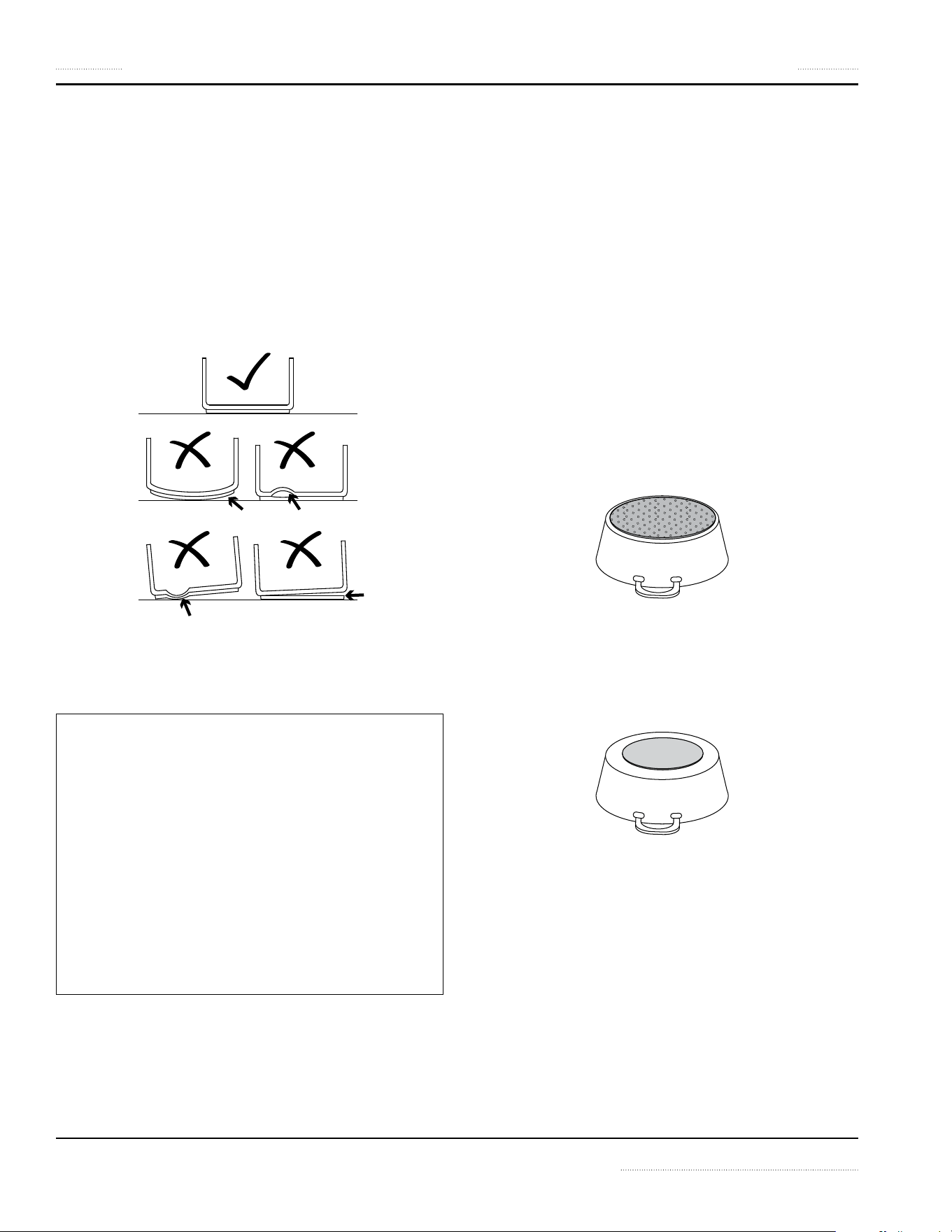
Important Rules—Operation and Maintenance
Follow these simple rules to ensure reliable and repeatable performance of your induction equipment:
1
Keep kitchen temperature below 40°C [105°F].
40
o
C/104
o
F
5
o
C/41
o
F
40
o
C/104
o
F
5
o
C/41
o
F
2
Never place your induction equipment next to any
grease generating or heat generating equipment.
3
Clean the intake filter at least once a week or as
often as required.
4
Use only pans that fits the glass. Do not use
oversized pans.
5
Never pre-heat the pan. Place the pan on the cook
zone only when you are ready to cook.
6
Do not use dented pans because it will cause
damages to the electronics.
20 Part Number 4520899 Rev 2 12/15
Operation Section 3
Proper Induction Cookware
CONDITION
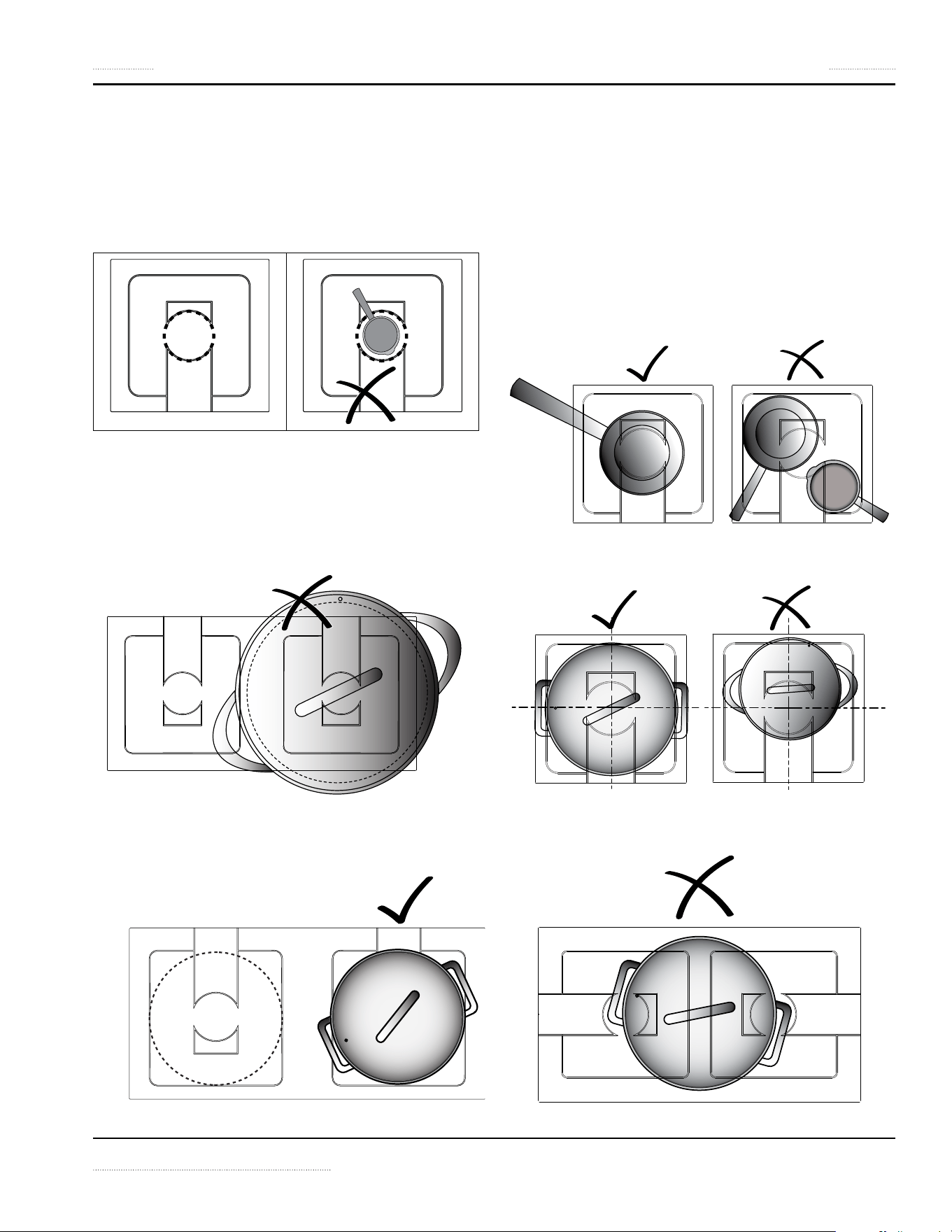
• Pans with layer separation (outward and inward
bubbles), arching or partially detached bottoms must be
replaced.
• When these pans are used, the sensors under the glass-
top cannot detect temperature correctly. These pans will
overheat the sensors and eventually will damage the
sensors and the generator. (Below, examples of good
and bad pans in cross-sections.)
ROUND BOTTOM WOK PANS
• For models with Ceran® Glass Wok Bowls:
Notice -Wok Equipment
Use Wok Pans with Correct Contour
The wok pans used must be the correct contour to the
Ceran® glass bowl. To reduce premature failures such as
overheating, wok pans should not touch the glass but
only sit onto the upper flange.
To guarantee the correct contour, we offer a selection
of wok induction pans. Please consult your equipment
supplier for details.
MATERIAL
• USE cookware made of conductive and magnetic
materials. If the pan bottom attracts a magnet, the pan
is suitable for induction cooking. Look for cookware that
is labeled suitable for induction or with an induction
compatible symbol.
• DO NOT USE cookware made of aluminum, copper,
glass, ceramics or conventional stainless steel.
• NOTE—Aluminum inserts on bottom:
Cookware base inserted with areas of aluminum
reduces the magnetic area for induction cooking. The
appliance may supply less energy to the cookware or
have difficulties in detecting the pan.
• NOTE—Non-magnetic cookware with a small magnetic
base:
The exposed non-magnetic metal on the base may
affect the induction field and subsequently, less energy
may be suppled to the cookware.
BOIL TEST
To test the efficiency of a pan for induction cooking, perform
a boil test. See instructions in section 5 Troubleshooting.
Part Number 4520899 Rev 2 12/15 21
Section 3 Operation
SIZE OF PAN
• MINIMUM SIZE: The bottom of pan must have a
minimum diameter of 12cm [5”] (below, dotted lines).
Otherwise, the pan will not be heated. This is a safety
feature such that the sensors do not detect small metal
objects, such as jewelery, and transmit energy to heat up
the small object.
• DO NOT USE OVERSIZED PAN! The bottom of the pan
must fit the glass. When a hot, oversized pan covers the
silicone seal underneath, the heat from the pan may dry
out the silicone overtime. When the silicone seal drys out
and breaks, liquid can penetrate into the appliance and
damage the electronics.
(A dual cook-top is shown as an example.)
• PAN MUST FIT THE GLASS! The best pan to use is the
one with a bottom that fits the coil (below, dotted lines).
(A dual cook-top is shown as an example.)
Placing Pan On A Cook Zone
Each cook zone of our appliances is equipped with the
latest RTCS® or RTCSmp® sensors. These sensors monitor
temperature and cookware continuously in realtime.
To obtain optimal results from the sensors, you must always
place pan in the center of the cook zone. Otherwise, the
bottom of the pan is heated unequally and the food inside
the pan may burn.
• PLACE MAXIMUM ONE PAN PER COOK ZONE.
• ALWAYS PLACE PAN IN THE CENTER OF A COOK ZONE.
• PAN MUST NOT COVER MORE THAN ONE COOK ZONE
ON A DUAL OR ON TWO SINGLE UNITS.
22 Part Number 4520899 Rev 2 12/15
Operation Section 3
Power Control
Set the desired power level by turning the control knob and
the appliance is immediately ready for operation.
• Power level (1) = lowest power
• Power level (9) = highest power for BH models only
• Power level (12) = highest power
When the indicator lamp shines continuously, energy is
being supplied to the bottom of the cookware.
ON-Position
Any position
other than “0”
is pointing to
the Indicator
lamp. The
lamp is on.
OFF-Position
“0” is pointing
to the
Indicator
lamp. The
lamp is off.
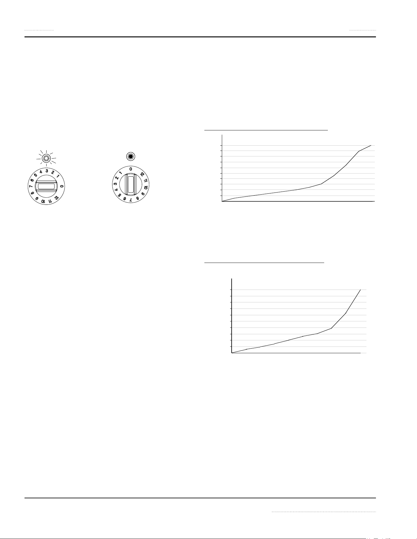
POWER LEVEL SETTINGS
The Power Diagrams (below) show that the difference in
power output between two higher power levels is much
larger than that between two lower power levels.
This power level and output relationship gives you a fine
simmer-rate control in the low power range, and an instant
response in the high power range.
POWER DIAGRAM 1: POWER LEVEL 0 TO 12
POWER
OUTPUT
0123456789 10 11 12
P O W E R LEVEL
100%
50%
10%
20%
30%
40%
60%
70%
80%
90%
The settings from (1) to (9) span the lower 50% of the
total Power Output; the settings from (10) to (12) cover
the 50% to 100% output range.
POWER DIAGRAM 2: POWER LEVEL 0 TO 9
(BH models only)
0
POWER
OUTPUT
P O W E R LEVEL
100%
50%
10%
30%
20%
40%
60%
80%
70%
90%
123456 7 8 9
The settings from (1) to (7) span the lower 50% of the
total Power Output; the settings from (8) to (9) cover the
50% to 100% output range.

Part Number 4520899 Rev 2 12/15 23
Section 3 Operation
Automatic Pan Detection, No Pan No Heat
When a temperature or a power level is selected, the
appliance supplies energy only when a pan is placed in the
cook zone.
When you remove the pan from the cook zone, the
appliance stops power supply immediately. If the pan is put
back in the cook zone, power supply resumes.
NOTE: Pan with a bottom diameter smaller than 12cm or 5” is
not detected by the system.
Reading the Signals from An Indicator Lamp
PAN DETECTION MODE: The appliance is in Pan Detection
mode when it is ON but without any pan sitting on the
surface of the cook zone. The indicator lamp flashes.
As soon as a pan is put into the cook zone, the pan engages
the heating process and the indicator lamp stops flashing
and remains bright. However, the indicator lamp will keep
flashing if the appliance is unable to detect the pan or an
unsuitable pan is used.
When a fault occurs, the indicator lamp flashes at intervals.
See section 5 Troubleshooting.
When Appliance Is Idle
BEST PRACTICE:
When the induction appliance is not in use, always put the
control knob in the 0 (OFF) position.
Notice
Switch the appliance OFF if you take the cookware away
for a while. This will prevent the heating process to start
automatically and unintentionally when a pan is placed
back on the heating area. If any person needs to use
the induction appliance, he/she will have to turn the
appliance ON intentionally.
24 24 Part Number 4520899 Rev 2 12/15
MAINTENANCE SAFETY—DISCLAIMER
DANGER
It is the responsibility of the equipment owner to
perform a Personal Protective Equipment Hazard
Assessment to ensure adequate protection during
maintenance procedures.
n
Warning
A good maintenance of the appliance requires regular
cleaning, care and servicing. The site-supervisor and the
operator must ensure all components relevant to safety
are in perfect working order at all times.
NOTE: Cleaning tools and supplies are not provided.
DANGEROUS ELECTRICAL VOLTAGE
DANGER
Do not open the appliance. Maintenance and servicing
work other than cleaning as described in this manual
must be done by an authorized service personnel.
DANGER
If any part of the appliance is cracked or broken, Stop
and Immediately Turn Off the appliance. Only if it
is possible and safe, disconnect the equipment from
main power supply. Do not touch any parts inside the
appliance.
Disconnect electric power at the main power disconnect
for all equipment being serviced.
Failure to disconnect the power at the main power
supply disconnect could result in serious injury or death.
The power switch DOES NOT disconnect all incoming
power.
Contact an authorized service agency for assistance.
MAINTENANCE SAFETY—CLEANING
n
Warning
Never use a high-pressure water jet for cleaning or hose
down or flood interior or exterior of the equipment
with water. Ensure that no liquid can enter into the
equipment.
n
Warning
Allow heated equipment / glass surface to cool down
before attempting to clean, service or move.
n
Warning
When cleaning the exterior, care should be taken to
avoid front power switch and the electrical cords. Keep
water and cleaning solutions away from these parts.
,
Caution
Do not use caustic cleaners on any part of the
equipment. Use mild, non abrasive soaps or detergents,
applied with a sponge or soft cloth.
,
Caution
Ensure to remove all residues of cleaning agents from
the cooking surfaces. Use a clean moist cloth to wipe off
any such surfaces.
,
Caution
Using commercial cleaning fluids or chemicals: Read the
directions for use and precautionary statements before
use. Pay attention to the concentration of cleaner and
the length of time the cleaner remains on the food-
contact surfaces or equipment surfaces.
Notice
Inspect and Clean Fresh Air Intake Filter
We strongly recommend using air intake filters in all
installations to protect the equipment from grease
particles. A dirty, blocked air intake filter blocks the
air vent and can cause damages to the electronic
components. Inspect, clean or replace the air intake
filters at least once a week or as often as necessary.
n
Warning
Inspect Silicone Seal
When the silicone seal is broken, water penetration
could cause the appliance to fail, and any malfunction
could cause personal harm.
Section 4
Maintenance
Part Number 4520899 Rev 2 12/15 25
Section 4 Maintenance
PERSONAL PROTECTION
DANGER
All utilities (gas, electric, water and steam) must be
OFF to all equipment and locked out of operation
according to national/regional, as well as company
approved practices during installation, maintenance
and servicing. Always allow appliance to cool.
DANGER
Use appropriate safety equipment during installation,
maintenance and servicing.
DANGER
Never stand, sit, or lean on the equipment! They are
not designed to hold the weight of an adult, and may
collapse or tip if misused in this manner.
DANGER
To avoid cardiac pacemaker malfunction, consult your
physician or pacemaker manufacture about effects of
electromagnetic field on your pacemaker.
n
Warning
Markings and warning labels mounted directly on the
equipment must be observed at all times and kept in a
fully legible condition.
n
Warning
Risk of burns from high temperatures. You may get burnt
if you touch any of the parts during operation. Surfaces
close to the cooking area including side panels may get
hot enough to burn skin. Use extreme caution to avoid
coming in contact with hot surfaces or hot grease. Wear
personal protective equipment.
,
Caution
Use caution when handling metal surface edges of all
equipment.
26 Part Number 4520899 Rev 2 12/15
Maintenance Section 4
Daily Cleaning and Maintenance
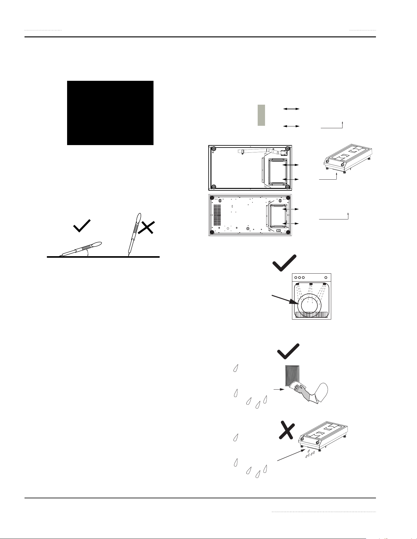
GLASS CLEANING
NOTE: The cleaning of Ceran® glass is identical to cleaning
other similar glass surfaces. You may use any regular glass
cleaning products available from a hardware store.
You may use a razor blade scraper or a non-scratching
sponge to remove tough residues. When scraping, place
your razor blade scraper at an angle of about 20
o
to 30
o
from
the glass. Then wipe clean the glass with a cleaning product.
20
o
- 30
o
STAINLESS STEEL CASE
1. For any appliance with stainless steel case or stainless
steel flange, clean the stainless steel surface using a soft
cloth with a mild detergent and/or a food-safe liquid
cleaner designed to clean stainless steel.
2. Wipe dry with a soft clean cloth.
VISUAL INSPECTION OF SILICONE SEAL
Inspect the silicone seal around the glass perimeter or the
joint between the appliance and the counter surface. Call for
service immediately if you notice:
• Cracks on the silicone seal.
• The silicone seal comes away from the glass/housing or
moves when you press down on the seal.
Weekly Cleaning and Maintenance
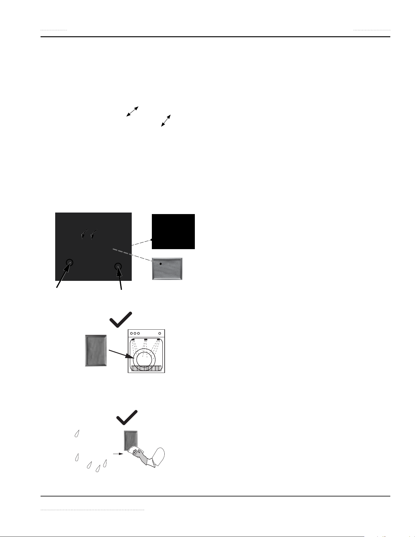
AIR INTAKE FILTER, COUNTERTOP MODELS
1. The air intake filter is located on the bottom of the
appliance. To remove, slid out the filter from the holder.
2. The filter is dishwasher-safe.
3. The filter must be DRY before you put it back into the
holder.
Part Number 4520899 Rev 2 12/15 27
Section 4 Maintenance
AIR INTAKE FILTER, BUILT-IN MODELS
For Air Intake Kits part numbers: 95000020, 9500021,
95000085.
1. Locate the filter, which is inserted into a holder
mounted onto the cabinet.
2. When a plastic holder is used, slid out the filter from the
holder.
When a metallic holder is used, press down on the
corners as shown to pop out the filter. If the filter
doesn’t move, try the opposite corners. The filter is
pressure fitted into the holder.
3. The filter is dishwasher-safe.
4. The filter must be DRY before you put it back into the
holder.
Yearly Maintenance
Best Practice: Have the induction appliance examined once
a year by an authorized technician.
28 Part Number 4520899 Rev 2 12/15
DANGEROUS ELECTRICAL VOLTAGE
DANGER
If any part of the appliance is cracked or broken, Stop
and Immediately Turn Off the appliance. Only if it
is possible and safe, disconnect the equipment from
main power supply. Do not touch any parts inside the
appliance.
Disconnect electric power at the main power disconnect
for all equipment being serviced.
Failure to disconnect the power at the main power
supply disconnect could result in serious injury or death.
The power switch DOES NOT disconnect all incoming
power.
Contact an authorized service agency for assistance.
DANGER
Do not open the appliance. Maintenance and servicing
work other than cleaning as described in this manual
must be done by an authorized service personnel.
n
Warning
Markings and warning labels mounted directly on the
equipment must be observed at all times and kept in a
fully legible condition.
NOTE: If a problem arises during operation of your
induction appliance, follow the Troubleshooting
Charts before calling service. Routine adjustments and
maintenance procedures are not covered by the warranty.
Common Problems
One or more of the following conditions may affect the
function or cause the induction equipment to fail:
• Using unsuitable cookware such as non-induction pans,
oversized pans, or damaged pans.
• High ambient temperature.
• Inadequate ventilation causing hot air to re-enter
through the air intake slots.
• Dirty air intake filter.
• Empty pan is left on the hob when the appliance is ON.
Symptoms
• When a malfunction occurs, the appliance may be in
one of the following states:
• The appliance switches off immediately.
• The appliance continues to operate in a power
reduction mode.
• The appliance continues to operate normally.
• Appliance equipped with an indicator lamp or a digital
display, see section Troubleshooting Chart — Error Code /
Flash Code.
• Appliance without an indicator lamp / digital display,
or the lamp is malfunction, see section Troubleshooting
Without Error Code / Flash Code.
• NOTE:
The cooling fan starts when the ambient temperature
in the control area exceeds 55ºC [130ºF].
At heat sink temperature higher than 70ºC [160ºF], the
controller automatically reduces power to keep the
appliance in normal operating conditions. The cooker
runs in a non-continuous mode. This mode can be
heard.
Boil Test
To test the efficiency of a pan for induction cooking,
perform a boil test.
This test is not applicable to griddles and braising pans.
NEVER heat any cooking pan on a griddle plate or in a
braising pan.
(Test for 3.5kW or 5.0kW Induction Coil)
Perform a boil test to verify the performance of a pan for
induction cooking.
• Add one liter of cold water into the pan (optimal when
use pan with bottom diameter of 24cm) and bring it to
boil. Compare the total boil time to the guideline below:
• 3.5kW Coil, approx. 140 seconds
• 5.0kW Coil, approx. 85 seconds
If time to boil exceeds the above guideline, then the pan is
not suitable for achieving optimal efficiency. Please contact
your supplier to purchase suitable induction pans.
If the induction appliance does not function as expected
despite using quality induction pans, refer to the
troubleshooting charts.
Section 5
Troubleshooting
Part Number 4520899 Rev 2 12/15 29
Section 5 Troubleshooting
Troubleshooting Without Error Code / Flash Code
Symptom Possible Cause Action
Pan does not heat up on glass-top.
No heat to griddle or braising pan.
Indicator lamp is OFF (dark).
Digital display is OFF (dark).
No power supply. Check incoming power supply (Example, power
cable plugged into the wall socket). Check kitchen
main fuse box.
Control knob is in OFF-position. Turn control knob to an ON-position.
Defective equipment Put knob in OFF-position. Only if possible and safe,
disconnect the appliance from the power supply.
Contact an authorized service agency.
Pan does not heat up and indicator
lamp blinks continuously. If Indicator
lamp blinks at intervals, see next
section.
(Not applicable to griddles or braising
pans.)
Pan is too small. Use a suitable pan with bottom diameter larger than
12cm[5”].
Pan is not placed in the center of the hob;
pan is not detected by sensor.
Move the pan to the center of the hob.
Unsuitable pan. Select only induction-ready cookware.
Defective equipment Put knob in OFF-position. Only if possible and safe,
disconnect the appliance from the power supply.
Contact an authorized service agency.
Poor heating, indicator lamp / digital
display is ON
Air-cooling system is obstructed. Verify that air vents are not obstructed. Ensure the
fresh air filter is clean.
Unsuitable pan. (Not applicable to
griddles or braising pans.)
Select various induction-ready cookware for
induction cooking. Then compare the results.
Ambient temperature is too high. The
cooling system is not able to keep the
appliance in normal operating conditions.
Verify that no hot air is taken in by the fan.
Reduce the ambient temperature. The intake air
temperature must be lower than 40°C [104°F].
One phase is missing (for equipment with
three phase supply only).
Check incoming power supply (Example, power
cable plugged into the wall socket). Check kitchen
main fuse box.
Defective equipment Put knob in OFF-position. Only if possible and safe,
disconnect the appliance from the power supply.
Contact an authorized service agency.
Appliance does not react to control
knob positions
Defective control switch. Put knob in OFF-position. Only if possible and safe,
disconnect the appliance from the power supply.
Contact an authorized service agency.
Power/heating level seems to be
reduced, fan is working
Air-cooling system is obstructed. Internal
fan is dirty.
Verify that air vents are not obstructed. Ensure the
fresh air filter is clean.
Contact an authorized service agency.
Power/heating level seems to be
reduced, fan does not work
Defective fan or fan control. Put knob in OFF-position. Only if possible and safe,
disconnect the appliance from the power supply.
Contact an authorized service agency.
After a long period of continuous
operation, the power/heating level
seems to be reduced
Overheated induction coil; cooking area
is too hot.
Overheated pan. Pan is empty.
Switch the appliance off. Safely remove pan, if any.
Wait until the appliance has cooled down before
turning it ON again.
Small metallic objects (e.g. spoon) are
heated up in the cook zone.
Pan detection function is defective. Put knob in OFF-position. Only if possible and safe,
disconnect the appliance from the power supply.
Contact an authorized service agency.
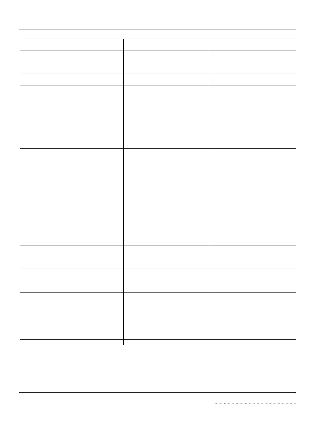
Troubleshooting — Error Code / Flash Code
• Appliance equipped with an indicator lamp:
The indicator lamp flashes to signal a specific problem. To find the possible cause, count the number of short flashes
after each long flash.
Example: “— …. — ….” The lamp gives a long flash for 0.6 seconds. Then it gives 4 short flashes (indicated by the dots in
the example). The sequence repeats until the error is canceled.
• Appliance equipped with a digital display:
The display may show an error code, example: E04.
30 Part Number 4520899 Rev 2 12/15
Troubleshooting Section 5
Number of Flashes
(Indicator Lamp)
Error Code
( Display)
Problem Action
...... Normal Operation. Normal Operation.
1 “
— . — . — . “ E01
Unsuitable induction cooking pan.
Internal wiring/coil connection
malfunction. (1)
Check pan material.
Contact an authorized service agency.
2 “
— .. — .. — .. “
E02 Unsuitable induction cooking pan. Coil/
software overcurrent. (1)
Check pan material.
Contact an authorized service agency.
3 “— ... — ... — ... “
E03 Air-cooling system obstructed. Fan mal-
function. Internal heat sink overheated.
(1)
Let appliance cool down.
Verify that air vents are not obstructed.
Check and clean air filter.
Contact an authorized service agency.
4 “
— .... — .... — .... “
E04
E17 E18
E27 E28
E41 E42 E43
E44 E45 E46
Overheated cook zone. Overheated pan
detected. Sensor failure. Overheated or
defective sensor. (1)
NOTE: Errors E41 to E46, griddles and
braising pans may continue to operate.
Let appliance and/or pan cool down.
Check pan material.
Verify that air vents are not obstructed.
Check and clean air filter.
Contact an authorized service agency.
5 “
— ..... — ..... — ..... “
E05 Power switch/potentiometer error. (1) Contact your authorized service agency.
6 “
— ...... — ...... — ...... “
E06
E30
Ambient temperature too high (the
cooling system is not able to keep the
induction appliance in normal operating
conditions). Internal component
overheated. (1)
Let appliance cool down.
Verify that air vents are not obstructed.
Check and clean air filter.
Verified that no hot air is taken in by the
fan. Reduce the ambient temperature. The
intake air temperature must be lower than
40°C [104°F].
Contact an authorized service agency.
7 “
— ....... — ....... — ....... “
E29
E47
Generator component failure. Problem
with control wiring. Warning from
overheated pan / cooking empty sensor
or coil connection failed. (1)
NOTE: E47 on griddles/braising pans
indicates that griddle plate is too hot.
Let equipment/ pan cool down.
Check food in the pan or empty pan.
Contact an authorized service agency.
8 “
— ........ — ........ — ........ “
E21
E24 E25 E26
Sensor error from heat sink or CPU.
Board overheated. Ambient temperature
beyond normal operating range. (1)
Verify that air vents are not obstructed.
Check air filter. Reduce ambient
temperature.
Contact an authorized service agency.
10 “
— .......... — .......... — .......... “
E10 Internal electronic failure. (1) or (2) Contact an authorized service agency.
No flash code E11 Multi-Line model only: 24V Voltage too
low. (1).
Contact your authorized service agency
to check power connection, 24V, power
board and display.
No flash code E12
E13
Power reduction. Warning of high
heat sink temperature. Cook zone
temperature too high. Sensor warning of
high temperature. (2)
Let equipment/ pan cool down. Check
pan material. Verify that air vents are not
obstructed. Check and clean air filter.
Verified that no hot air is taken in by the
fan. Reduce ambient temperature. The
intake air temperature must be lower than
40°C [104°F].
Contact an authorized service agency.
No flash code E19
E20
Warning of high internal temperature. (2)
No flash code E22 Griddle only. RTCS/CU sensor defect. (1) Contact an authorized service agency.
(1) The appliance switches off immediately.
(2) The appliance continues to operate in a power reduction mode.
(3) The appliance continues to operate normally.

GARLAND
1177 KAMATO ROAD, MISSISSAUGA, ONTARIO, CANADA, L4W1X4
888-442-7526
WWW.GARLAND-GROUP.COM
To learn how Manitowoc Foodservice and its leading brands can equip you, visit our global web site at
www.manitowocfoodservice.com, then discover the regional or local resources available to you.
©2014 Manitowoc Foodservice except where explicitly stated otherwise. All rights reserved.
Part Number 4520899 Rev 2 12/15
Every new piece of Manitowoc Foodservice equipment comes with KitchenCare™ and you choose the level of service that meets
your operational needs from one restaurant to multiple locations.
StarCare – Warranty & lifetime service, certied OEM parts, global parts inventory, performance audited
ExtraCare – CareCode, 24/7 Support, online/mobile product information
LifeCare – Install & equipment orientation, planned maintenance, KitchenConnect™, MenuConnect
Talk with KitchenCare™ • 1-844-724-CARE • www.mtwkitchencare.com