Due to our commitment to continued product improvement, specications are subject to change without notice. Rev. 5/2023
Krowne • 100 Haul Rd. Wayne, NJ 07470 • P: (800) 631-0442 • F: (973) 872-1129 • customerservice@krowne.com • krowne.com
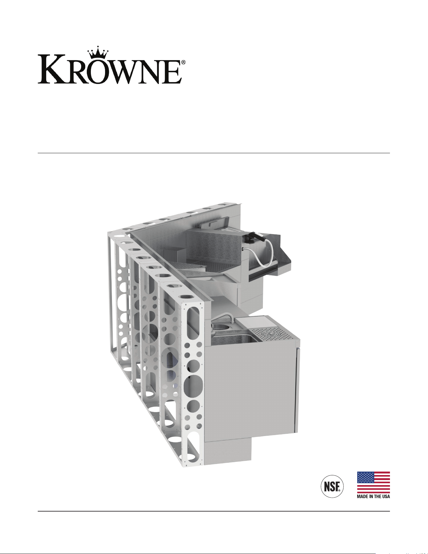
Modular Bar Die
Installation Manual
Questions? Contact us at (800) 631-0442 or [email protected]
Modular Bar Die Installation Manual
2
Modular Bar Die
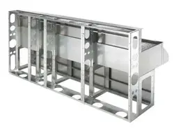
Built-in chaseways for soda, beer, electrical & plumbing lines.
Elimination of legs create a sealed-to-floor finish.
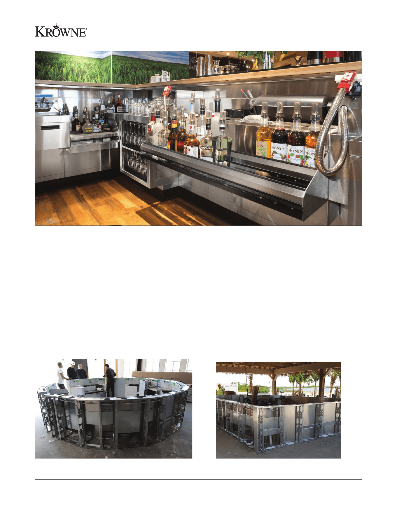
Krowne Modular Bar Die (KMB) is designed to significantly reduce installation time while improving overall aesthetics
and cleanability. The most time consuming portion of an underbar installation consists of the field layout/assembly of
bar sections, and the construction of the bar frame in which the sections are attached.
Our modular bar units ship completely assembled in sections up to 8 ft. to drastically cut down time and labor while
ensuring a sleek finish. Replacing legs with stainless steel panels that mount flush to the floor prevent debris from
building up under the equipment.
Available in any shape or size Built for indoor and exposed applications.
Questions? Contact us at (800) 631-0442 or [email protected]
Modular Bar Die Installation Manual
3
Bar die structure fabricated out of 16 ga. galvanized steel (stainless steel finish on bartender side to hide drains & plumbing)
Bartender-side: 20 gauge 300 series stainless steel
Units pre-assembled at factory and shipped in sections up to 8’ for easy installation (cuts installation costs)
Supports 1,000 pounds per foot of downward force
Built-in chaseways for plumbing, electric, soda, beer, and other utility lines
Die wall sealed-to-floor design prevents seepage
Bar top and front panels can be easily installed to structure
No legs required. Units attached to bar die structure for quick and easy cleaning.
Built-in electrical outlets installed per customer’s request (quantity and location to be verified)
Bartender-side panels removable for drain access
End panels (by millwork) easily removed for access to soda, beer, electrical and plumbing lines for future service or repair
We recommend customer-side panels are built by millworker to be removable
Bar die can be upgraded to stainless steel
Advantages to Modular Bar Die
Modular Bar Die Specifications
Tools Required
Phillips head screw driver
Level
Tape measure
Chalk line
Power drill
Shims for leveling
7/16 ratchet wrench
7/16 box wrench or
adjustable wrench
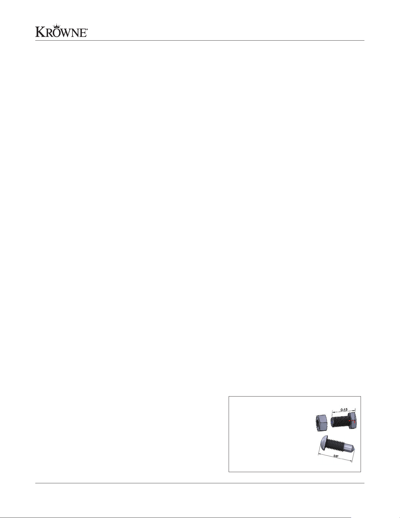
1/4” x 7/16 hex head bolts and
nuts (used for adjoining modular
bar sections to each other. Krowne
suggests that the hex heads that are
included be sealed with sealant upon
installation.).
#8 Self starting galvanized screws
(used for modular front panels &
anchoring to floor).
Fasteners are supplied
in a plastic bag with
your bar die.
Make sure all screws are
facing the same direction
when adjoining modular
sections for maintenance
purposes.
For proper installation, it is important to have the following tools on hand before starting the installation.
Mechanical
Utility
Electrical
Plumbing
General Specifications
Utility lines: Dedicated chase locations for hot/cold water
supply lines, beverage line conduits, and electrical conduit
(behind the underbar equipment) this chase is accessible
from the floor and runs the entire length of the bar.
Floor drains: Locate floor drains directly below workboard
equipment. The number of floor drains will vary depending
on the bar layout and local codes.
Millwork: Done by outside contractors
A 5-1/2” open zone is furnished behind the equipment to
provide room for various lines (trunk lines, soda lines,
plumbing, electrical, etc.) to travel vertically or horizontally
within the bar structure. Connections can be made from the
front of the bar with panels removed.
All electrical requirements such as receptacle to blenders,
washers, coolers, soda guns, light, etc. (by others).
All water service and waste connections can be made
from the front of the bar (decorative front panel removed).
Local codes dictate installation (by others).
Structure: Configured to the exact size and shape
of underbar equipment, freestanding cabinets and
openings, as specified.
Chase: Interior chase runs the entire length of the
structure including corners.
Millwork: Done by outside contractors
Questions? Contact us at (800) 631-0442 or [email protected]
Modular Bar Die Installation Manual
4
LED Light Specifications
Wiring Example 12/24/V DC No Dimming
Models
25 Watt Power Supply (KMB-PS-25)
60 Watt Power Supply (KMB-PS-60)
Features
No glare, down-angled beam. Rugged and
waterproof. Brushed nickel oval bezel. In-
cludes stainless steel pre-punched wall plate,
(1) 2” x 4” electrical box
Colors Cool Blue (KMB-LK-B)
Input Voltage 9-30V DC, 9-15V AC
Input Power 1.5 Watts Typ, 2.5 Watts Max
Lumens 17 lms typ @3000 °K
IP Rating IP67
Wiring 6” Twisted 18 AWG
Recommended spot for LED power
supply and switch on diagram:
The master switch location is determined
by customer preference but we recom-
mend not placing it near a sink and it must
meet local district code. Follow these
same guidelines for the outlet location.
The transformer should be installed in the
back of the mod wall and it must be easily
accessible by local district code. We
recommend having it plug into an outlet.
AC Adapter (not included) - Plug into
building wall receptacle. Receptacle
to be controlled by a wall switch.
Receptacle and wall switch by electrical
contractor.
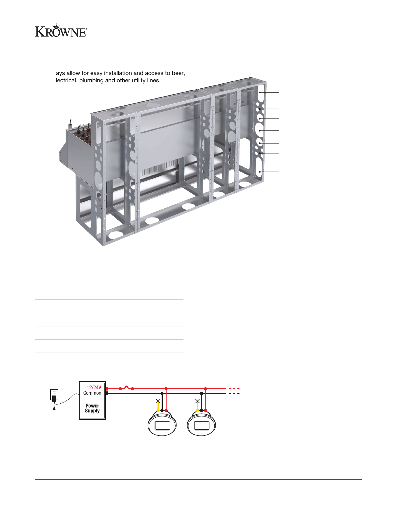
Chaseways allow for easy installation and access to beer,
water, electrical, plumbing and other utility lines.
Modular Bar Die Chaseways
Vent Line Chase
Electrical Chase
Extra Utilities
Beer Chase
Soda Chase
Water Line Chase
Plumbing Chase
Questions? Contact us at (800) 631-0442 or [email protected]
Modular Bar Die Installation Manual
5
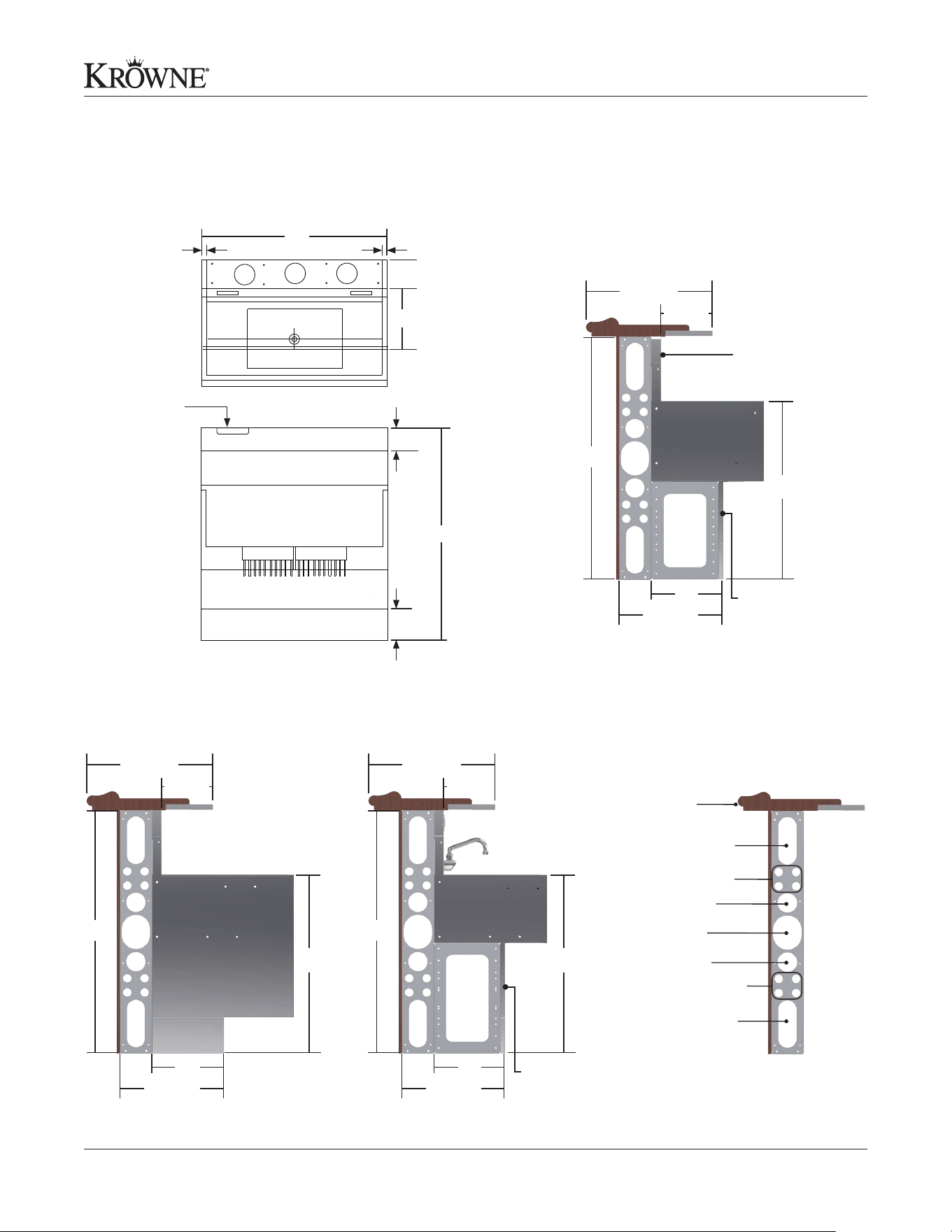
Typical Bar Sections with Modular Bar Die
D
Soda Manifold
Cutout
12”
4-1/2”
6”
41”
5-1/2”
36”
1”1”
Modular Bar Die Chases
Vent Line Chase
Electrical Chase
Extra Utilities
Beer Chase
Soda Chase
Water Line Chase
Plumbing Chase
Bar Top &
Front Finish
by others
Cabinet (Side View)
24”-26”
17-1/2”
12”
41”
9”-10”
30”
Bar Sink (Side View)
Removable
Panel
24”-26”
17-1/2”
12”
41”
9”-10”
30”
Ice Bin (Side View)
Removable
Panel
Removable
Panel
24”-26”
17-1/2”
12”
41”
9”-10”
30”
Questions? Contact us at (800) 631-0442 or [email protected]
Modular Bar Die Installation Manual
6
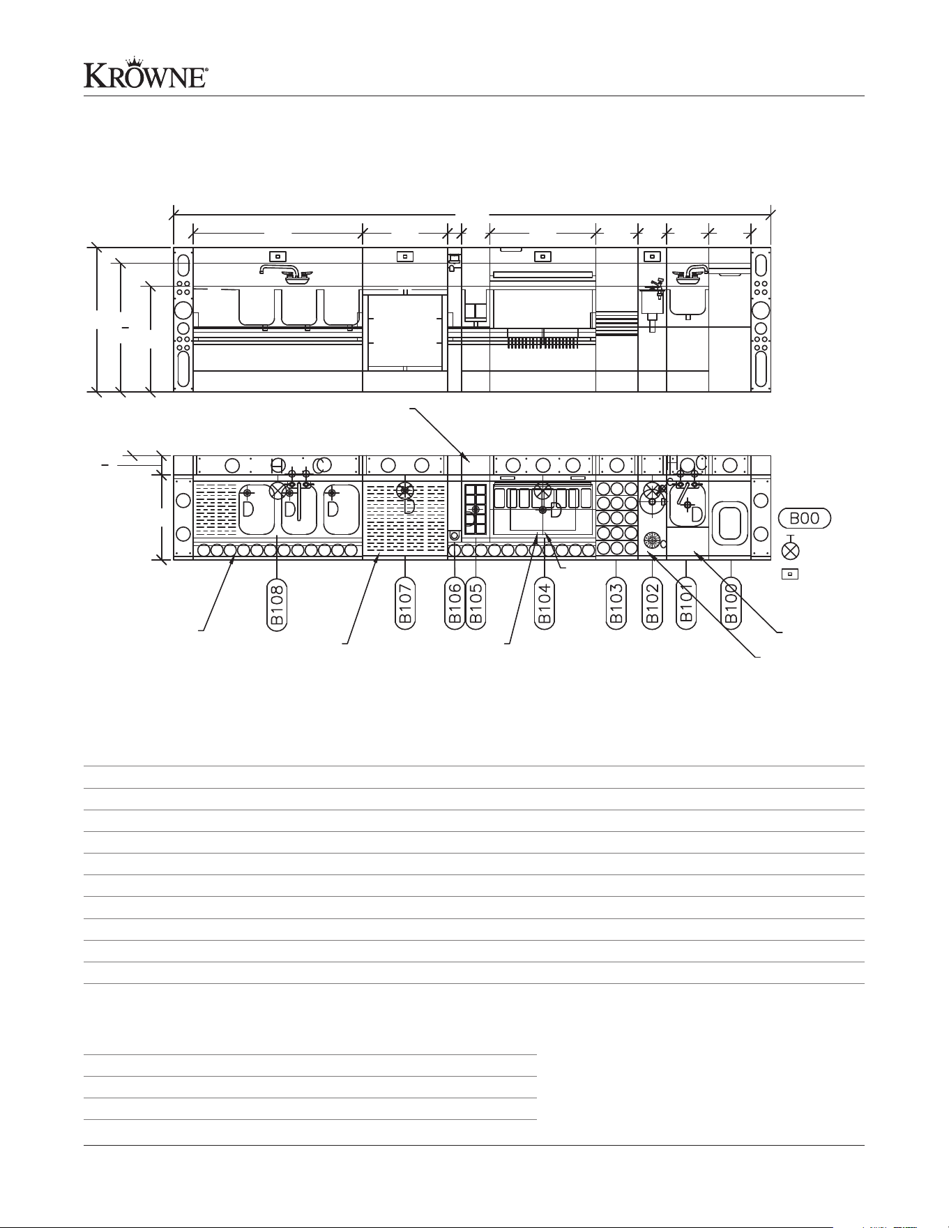
Below is an example of a typical bar assembly using modular bar die.
Typical Equipment Schedule
LED Lights and Outlets
No. Qty Krowne Model Description Equipment Remarks
B00 23 KMB Modular Bar Die System
B100 1 KR24-T12 12” Dry Waste Trash Chute
B101 1 KR24-MC12 12” Speed Unit with Dump Sink, Cutting Board
B102 1 KR24-MD8 8” Speed Unit with Dipperwell, Speed Rinser
B103 1 KR24-ML12 12” 5-Step Liquor Display RS-42; KR-521
B104 1 KR19-30-10 30” Ice Bin with Cold Plate
B105 1 KR19-ME8 8” Elixir Station
B106 1 KR19-4SH-L 4” Soda Gun Holder
B107 1 KR24-GSB1 24” Glass Storage Cabinet with 3 Adjustable Racks
B108 1 KR19-43R 48” 3-Compartment Bar Sink RS-48
Model Description
KMB-LK-B Cool Blue LED Light (1.5 Watts Output)
KMB-PS-25 25 Watt Power Supply for up to 10 LED Lights
KMB-PS60 60 Watt Power Supply for up to 25 LED Lights
24"
5
1
2
"
48"
24"
4"
8"
30"
12"
8"
12" 12"
169"
LED (W) LED (W) LED (W) LED (W)
41"
36
1
2
"
30"
ELIXER STATION
(WHEN SPECIFIED)
DIPPER WELL WITH
GLASS RINSER
(WHEN SPECIFIED)
CUTTING BOARD
HOLDS APP.
15 BOTTLES
LED LIGHT
3 BOWL SINK WITH LIQUOR
RAIL IN FRONT TO EXTEND
FULL LENGTH SINK
TYPICAL GLASS STORAGE
CABINET SECTION, HOLDS 3
GLASS RACKS, APPROX. 84
GLASSES (WHEN SPECIFIED)
GARNISH STATION WITH
SLIDING COVER WITH LIQUOR
RAIL IN FRONT TO EXTEND FULL
LENGTH (WHEN SPECIFIED)
ICE BIN
DIVIDER
Typical Bar Assembly Detail with Modular Bar Die
Questions? Contact us at (800) 631-0442 or [email protected]
Modular Bar Die Installation Manual
7
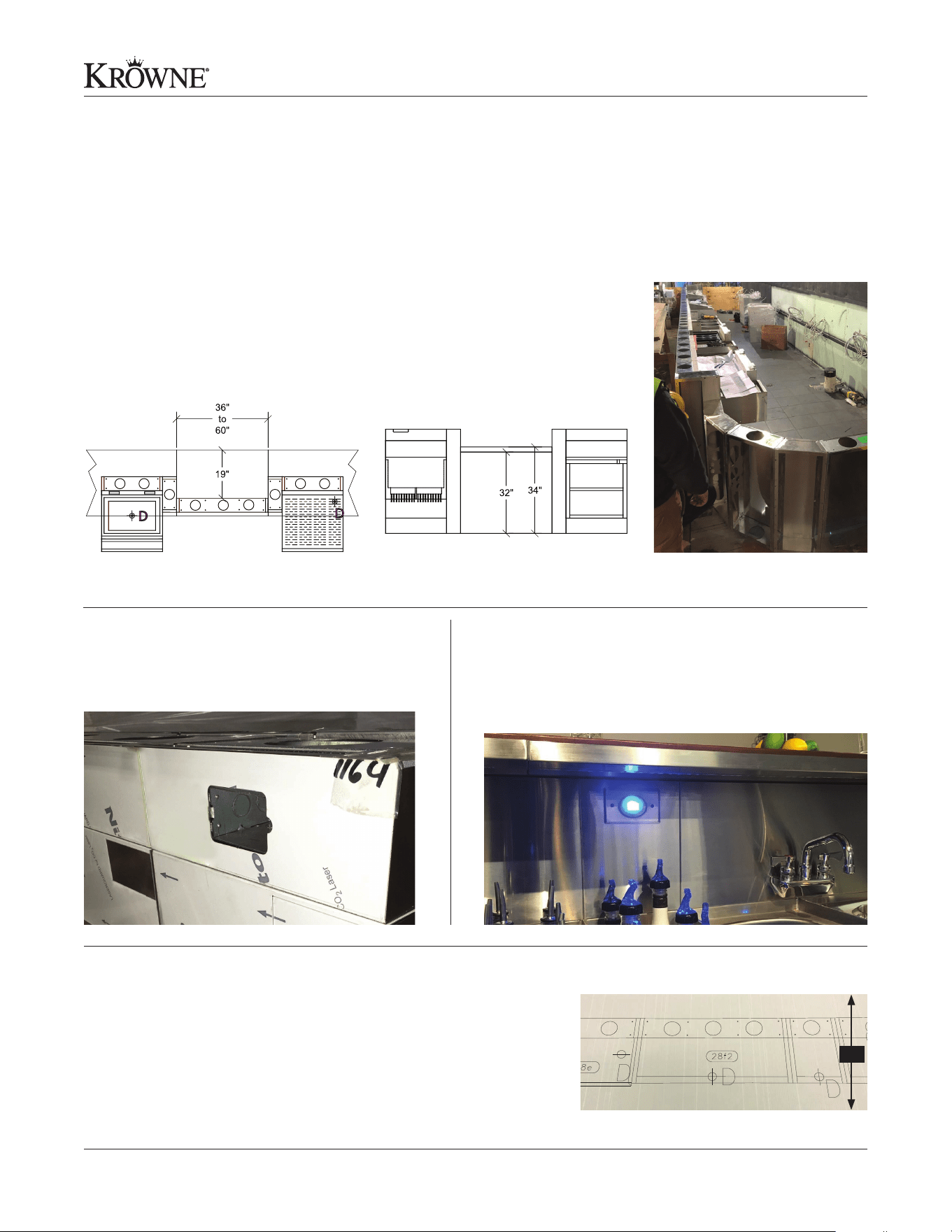
Providing an equal opportunity to people with disabilities is the fundamental principle of the American with Disabilities Act.
Krowne embraces this and provides options to have wheel chair accessible modular bar die added as an option.
Built-in electrical outlet boxes installed per customer’s
request (quantity and location to be specified).
Mylar template can be ordered prior to equipment going into production
and is used to see precise footprint of modular bar equipment. Template
is priced out per linear foot and is sent in sections labeled A thru Z for
ease of layout. Template allows for accurate marking of floor drain
locations and beer/vent lines along with the added benefit of spatially
visualizing your future bar. Mylar sections are sent in up to 200” in length.
Illuminate your bar with down acting LED lights. Color op-
tions include crisp white, warm white, blue, green, cyan, and
red. Power supply may also be purchased with LED lights.
ADA Certified
Built-In Outlets
Mylar Template
LED Lights
ADA Requirements for Foodservice Counters and Bars
Where food or drink is served at counters exceeding 34” (865 mm) in height for
consumption by customers seated on stools or standing at the counter, a portion of
the main counter, which is 60” (1525 mm) in length minimum, shall be provided in
compliance with 34” maximum counter height and 19” clear depth, or service shall
be available at accessible tables within the same area.
Confirm size with local codes. 36” to 60” depending on local code requirements
36”
Options
Questions? Contact us at (800) 631-0442 or [email protected]
Modular Bar Die Installation Manual
8
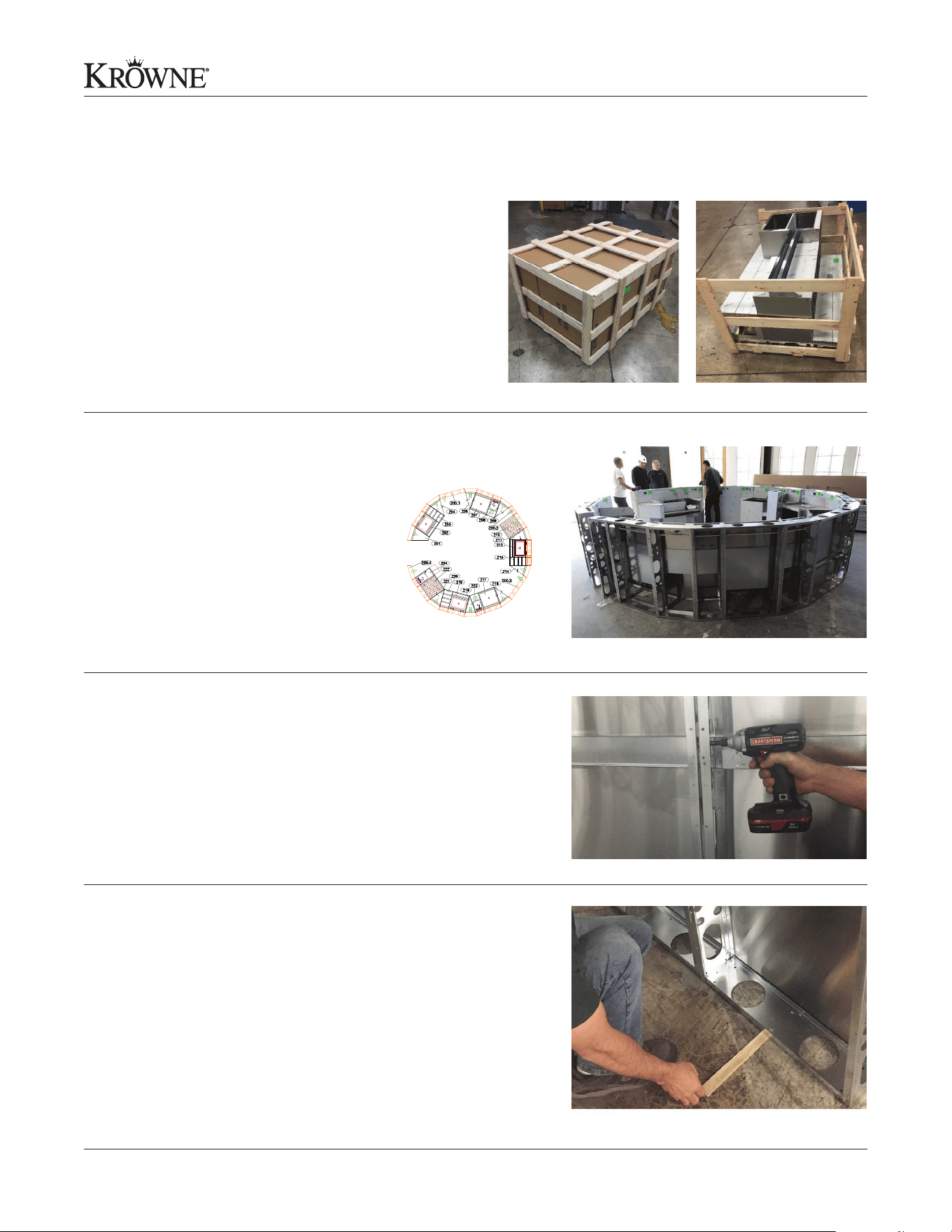
Remove all shipping material from units. Inspect the units for
any damage that could have occurred in transport. Report any
damage immediately to Krowne by calling 800-631-0442.
Set units in place according to the CAD
drawings provided with equipment in the box
marked “Parts and Instructions.” Die wall
should be placed over existing soda/beer line
conduits, plumbing and
electrical stub ups.
After units are set in desired location, loosely attach sections using
the hex bolts and nuts supplied with equipment (7/16 ratchet and
box wrench will be needed for this step). Krowne suggests that the
hex heads that are included be sealed with sealant upon installation.
After all sections have been bolted together and placed in the
desired location, units should be leveled using shims. (Shims
and standard level required for this step).
1. Uncrating
2. Placing
3. Adjoining
4. Leveling
40°
35°
35°
35°
35°
35°
35°
40°
D
D
D
D
D
D
D
D
D
D
C
H
C
H
C
H
Installation
Questions? Contact us at (800) 631-0442 or [email protected]
Modular Bar Die Installation Manual
9
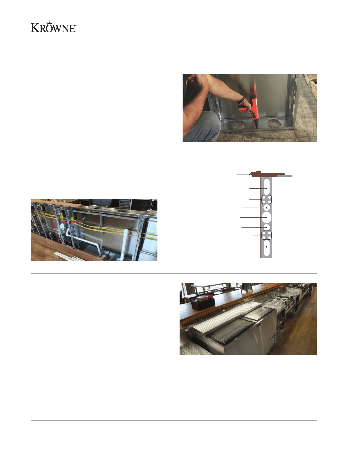
Once all units are fully leveled, tighten all bolts and nuts. Next,
attach the modular bar die to the ground through pre-cut 1/4”
holes on the bottom of the die wall. Your contractor will pick
the best installation method for your application.
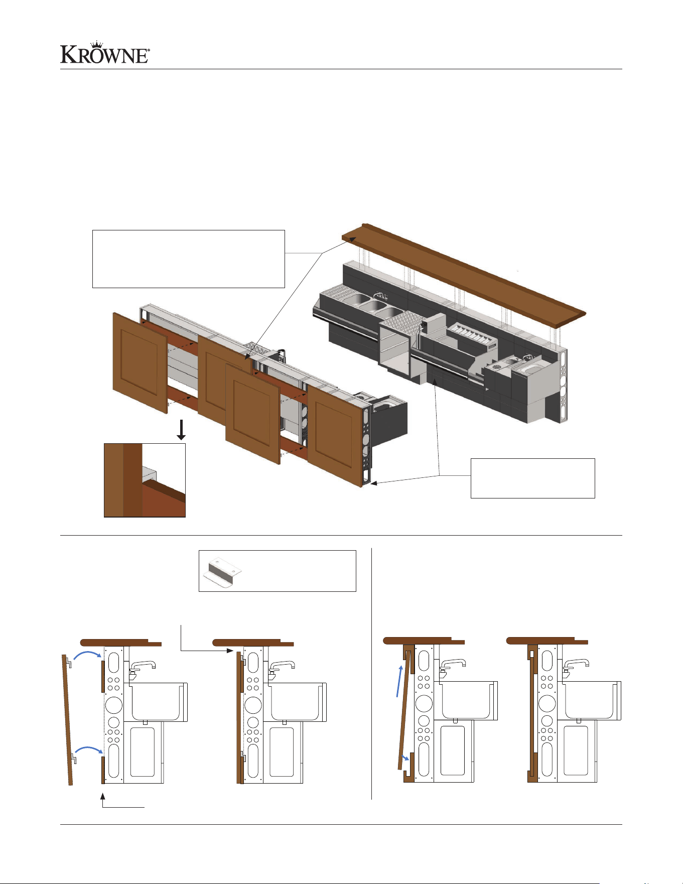
All plumbing, electric, beer, soda & vent lines should be installed
by a licensed professional to maintain factory warranty. Refer to
diagram for proper placement of all lines.
Free standing equipment such as bottle coolers, mug
frosters, back bar, and glass washers can be placed into
their designated sections according to the floor plan.
Bottle coolers and mug frosters should be installed with
a 2” gap on the left side for proper ventilation. Krowne
includes this 2” gap in layout drawings.
We recommend using NSF approved silicone to seal all joints near the floor (SIL-BOND 45000 RTV Silicone Sealant –
Aluminum). Tile can be abutted to the front floor panels and then sealed.”
5. Anchoring
6. Utility Lines
7. Freestanding Units
8. Sealing
Vent Line Chase
Electrical Chase
Extra Utilities
Beer Chase
Soda Chase
Water Line Chase
Plumbing Chase
Bar Top &
Front Finish
by others
Installation
Questions? Contact us at (800) 631-0442 or [email protected]
Modular Bar Die Installation Manual
10
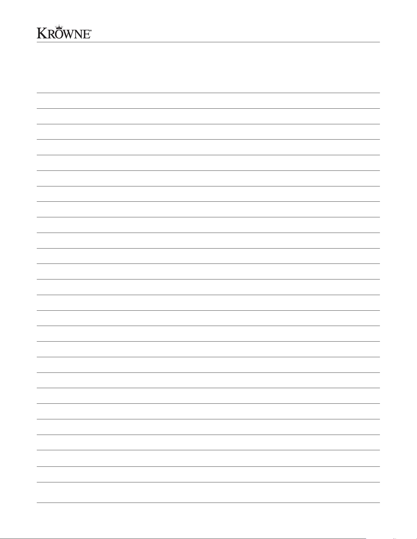
All underbar equipment and
bar die wall provided by
Krowne as specied.
Bar top and millwork panels to be provided
by millwork fabricator and installed in the
eld after bar equipment is set. Food service
equipment dealer to coordinate.
Z-clips are attached to
the inside of the bar front panel.
Model KMB-PC
Stainless Steel Z-CLIPS
with 3/4” offset (24 PACK)
METHOD A METHOD B
Metal Z-clips are attached to the
inside of the bar front panel.
Slide panel into channel created by
two pieces of wood.
Wood should be 3/4” thick to t Z-clips
Panels should be milled to leave a space approximately the width of a
z-clip leg. This allows for easy panel removal for maintenance.
Install bar counter and removable front millwork panels. It is very important to have the front panels removable to allow
access from the customers side for plumbing, electrical and beverage lines. Front panels use interlocking panels and hidden
screws meaning they make accessing the underside of the bar very easy and the screws cannot be seen by customers.
9. Front Panels
(Everything shown in brown is supplied by millworker.)
Installation
Questions? Contact us at (800) 631-0442 or [email protected]
Modular Bar Die Installation Manual
11
Notes

100 Haul Rd. Wayne, NJ 07470
P: (800) 631-0442
krowne.com
Due to our commitment to continued product improvement, specications are subject to change without notice. No. KMB-Manual

