MASTER GUIDE
Firstech, LLC.
21903 68th Ave S.
Kent, WA
98032
Phone.
888-820-3690
Fax.
206-957-3330
Please visit www.firstechdata.com for additional installation resources

Alarm
and
Starter
System
www
.firstechdata.com
CM900
Master
Guide
Copyright 2022 Firstech , LLC. “Talk to me Goose…
”
Page
2
T
able
of
Contents
Wire Schematic
3
Introduction
4
Kit Contents
4
Installation Basics
5
Remote
Programming Routine
6
Valet Mode
6
Placement and Use of Components
8
Common Procedures
1
3
Wiring Descriptions
1
7
Feature
Programming Tables
2
4
Feature
Option
Descriptions
2
9
Special Option Groups 1
& 2
4
7
Option Programming
steps
50
Troubleshooting
55
Frequently Asked Questions
56
Contacts and Support Pages
Resource and Tech support web sites
58
59
Alarm
and
Starter
System
www
.firstechdata.com
CM900
Master
Guide
Copyright 2022 Firstech , LLC. “Talk to me Goose…
”
Page
3
CM-900S Wiring
Schematic (Remote
St
a
r
t
)
CM-900AS Wiring
Schematic (Alarm-Remote
St
a
r
t
)

Alarm
and
Starter
System
www
.firstechdata.com
CM900
Master
Guide
Copyright 2022 Firstech , LLC. “Talk to me Goose…
”
Page
4
Introduction
Thank you!
For selecting a Firstech remote start security system as your product of choice. The following manual is a
complete Master guide to the CM900 universal Control Module and is intended for experienced and
authorized Firstech technicians only. If you need any further technical support, please call us at 888-820-
3690 dial 9 then ext. 203 or visit our website at www.firstechdata.com
Caution: The Manufacturer’s warranty will be void if this product is installed by anyone other
than an authorized Firstech dealer. Firstech provides installation support services to authorized
dealers only.
This manual may change frequently. Please check www.firstechdata.com for updates.
Kit Contents
All Firstech CM900 bundles include the following:
• CM900S or CM900AS main control module
• Wiring diagram sheet
• High Current ignition harness with one external relay (CM900AS only)
• Additional I/O Wiring harnesses
• Hood pin
• Mountable bright blue LED (CM900AS only)
• FT-SHOCK II dual stage impact sensor (CM900AS only)
• RF Kits with remote(s), Antenna, and Antenna Cable
The following sensors are available but not included with every system:
• Drone X1
• Temperature sensor (FT-TEMP SENSOR)
• DAS II (2 stage impact, Tilt, Glass break all in one sensor)
The remote(s) and antenna are modular and are not specific to the control modules. You can pair almost any
Firstech remote(s) and antenna receiver to the CM900 control module.
Any questions on contents please contact your distributor or us directly at 1.888.820.3690, Monday
through Friday, 6-AM to 6-PM Pacific Time.

Alarm
and
Starter
System
www
.firstechdata.com
CM900
Master
Guide
Copyright 2022 Firstech , LLC. “Talk to me Goose…
”
Page
5
Installation Basics
If you are new to installing Firstech Series Remote Starts and/or Alarms, we highly recommended that you
thoroughly review this manual to installing your first unit.
Remote Programming:
You must code remotes to this system before anything will function. Begin by cycling the ignition ON and OFF
five times within 10 seconds and press and release the Lock button (half second) on the first remote, and then
press and release Lock button (half second) on the second remote. Make sure to program a remote in each of
the 4 remote banks. You may program single remote into multiple banks if necessary
The CM900 will be set to Tachless mode out of the box. If you wish to use Tach mode, complete the Tach
programming procedure as described below and the CM will automatically switch to Tach mode.
Tach learning procedure: When using tach mode this must be done before the first remote start attempt.
Learn tach by: (1.) Starting the vehicle with the key, (2.) Press and hold the foot brake, then (3.) Activate the
remote start sequence - one chirp and parking light flash indicates that the vehicle tach signal has been
successfully learned. Two chirps and three parking light flashes indicate that the control module failed to see a
proper tach signal. (These units have the option for Tachless and 3 second assume cranking).
High Current 2nd Ignition Output (CN1 Blue Wire) (Jumper Programmable)
High Current Parking Light Output (CN1 Green/White Wire) (Programable Feature 1-06)
High Current Accessory Output (CN1 White Wire)
Optional Low Current Harness (FT-LC1) Available
2nd RS232 Data Port (Grey CN5) Default DroneMobile Protocol
Lock connector functions added to I/O Connector
Lock connector functions are now available via POC’s There is also a lock connector for FT- DM600/FT-
DM700 on rear of Control Module.
Built-In Troubleshooting diagnostics
Notice! In order to properly diagnose remote start/stop failure the parking light output must be connected to
either (+) Positive or (-) Negative parking light circuit on the vehicle.

Alarm
and
Starter
System
www
.firstechdata.com
CM900
Master
Guide
Copyright 2022 Firstech , LLC. “Talk to me Goose…
”
Page
6
Remote Programming Routine
IMPORTANT: All remotes must be coded to the control module prior to performing all operations.
STEP 1: Activate programming mode by manually turning the vehicle’s key between the Ign On and Off
(or the Acc & On positions) five times within 10 seconds. The vehicle’s parking lights will flash
once with the successful completion of this step.
STEP 2: Within a 2 second period after the 5th ignition cycle tap (a quick 0.5 second press and release)
the Lock button on the Firstech remote. The parking lights will flash once to confirm the
transmitter has been coded. Repeat step 2 for each additional remote, up to 4.
Note: if you only have 2 remotes please program each remote twice.
**parking lights will flash twice signaling the end of programming mode.
Remote programming procedure: PTS (Push to Start vehicles) application
STEP 1: Set the vehicle to the ignition or “ON” position
STEP 2: Within 5 seconds push to the “OFF” position
STEP 3: Within 5 seconds set the vehicle to the ignition or “ON” position (do not start)
STEP 4: Within 5 seconds depress and release the foot brake 3 times *parking lights will flash 1 time to
indicate remote programming is enabled
STEP 5: Tap (a quick 0.5 second press and release) the lock button on the remote * the parking lights
will flash 1 time indicating the remote code has been accepted (Repeat step 5 for each
additional remote, up to 4
STEP 6: After 10 seconds of no valid remote codes being transmitted the CM will automatically
exit programming mode
Valet Mode
Valet Mode disables all system features except for the keyless entry. Use Valet when servicing or loaning your
vehicle to others to avoid any inconvenience or mishap when operating the vehicle. There are no visual
indicators when the security system is in Valet Mode. There is a parking light diagnostic flash when remote
starting in Valet Mode. (3 flashes followed by 10 flashes). Also, when in Valet Mode, the keyless entry feature
will still operate.
The system can be put INTO valet mode one of 5 ways:

Alarm
and
Starter
System
www
.firstechdata.com
CM900
Master
Guide
Copyright 2022 Firstech , LLC. “Talk to me Goose…
”
Page
7
1. While holding the foot brake (12V+ brake input), cycle the key to the Ignition or ‘On’ position and then
back to the ‘Off’ position 5 times within 10 seconds. The parking lights will flash once indicating that the
system has entered Valet Mode.
2. Turn the key to the Ignition or ‘On’ position then using a 4-button remote press and release the lock and
trunk buttons together simultaneously for a half second. The vehicle parking lights will flash 1 time to
indicate the system has successfully entered valet mode. When using 3 or 5-button remote there will be
remote specific steps to enter valet, please see remote user’s manual for further instructions.
3. The user may enter valet mode by performing the PTS vehicle remote programming procedure and make
sure there are no remotes transmitting.
4. Drone Mobile app will allow a user to enable/disable VALET mode within the vehicle settings section.
1. Open the Drone Mobile app
2. Open settings
3. Open “Vehicles”
4. Select Vehicle
5. Open “System”
6. Toggle Valet on or off
7. Tap “Save” top right corner of the app.
**NEW
5. The CM900AS supports a (+/-) wired Valet mode input that can be connected to a latching or momentary toggle
switch (NOT INCLUDED). ENTER and EXIT valet mode will use the same procedure. NOTE: When the
system has been set to wired valet mode input, procedure 1 WILL NO LONGER FUNCTION!
1. Hold the Valet input to (+/-) for minimum of 5 seconds
2. After 5 seconds to ground, tap the Valet Input to (+/-) 5 times
3. The park lights will flash
-1 time for enter Valet mode
-2 times for exit Valet mode
NOTE: When using this feature with security features please make sure the switch is mounted
discretely and the user knows where to find the switch in case of emergency.
The System can be taken out of Valet mode by one of the following procedures:
1. No Remote: If there are no remotes programmed or there are no remotes available you can exit Valet
Mode by turning the key to the ignition on or ‘Run’ position then press and release the foot brake pedal
10 times within 10 seconds. This procedure will only deactivate Valet Mode it will not activate Valet
Mode. The vehicles parking lights should flash 2 times to indicate the system has exited valet mode

Alarm
and
Starter
System
www
.firstechdata.com
CM900
Master
Guide
Copyright 2022 Firstech , LLC. “Talk to me Goose…
”
Page
8
2. With Remote: While within remote range of the vehicle, using a 4-button remote, press and release the lock
and trunk button together simultaneously for a half second. The vehicle’s parking lights will flash 2 times to
indicate the system has exited Valet Mode. When using 3 or 5-button remote there will be remote specific
steps to exit valet, please see remote user’s manual for further instructions.
3. Using Drone mobile app as stated above.
4. Using the Wired Valet Input procedure as explained above
Placement and Use of Components
IMPORTANT: The placement and use of components are critical to the performance of this system.
Antenna and Cable
Firstech antennas are calibrated for horizontal installation at the top of the windshield. The cable that connects
the antenna to the control module must be free from any pinches or kinks. Installing the antenna in areas other
than the windshield may adversely affect the effective transmitting distance of the remotes.
FT-Shock II
This is an analog dual stage impact + a fixed 2.5 degree tilt sensor included with the CM900AS kit. The
CM900AS is default to accept the FT-shock II and provides warn away and full trigger outputs for both Shock
and Tilt. There is a dial located at the end of the FT-shock II with settings from “off” then 1-10 sensitivity level,
1 being the least sensitive and 10 being the most sensitive (10 will pick up the wind blowing ). We
recommend mounting the sensor with the plastic mounting strap included preferably as centered to the vehicle
as possible. Due to its extreme sensitivity the vehicle plastic heater ducting makes for a good mounting surface.
The Tilt portion is auto calibrating so once its mounted, then armed it will look for a 2.5 degree tilt from that
location.
LED (external)
There will be an external mountable Blue LED for theft deterrent included. It is important to discuss mounting
locations with the end user, trying to make it visible and bright when recommending locations. The LED will
light up solid blue when armed for approx. 25 seconds allowing the impact sensor to set up. Once the LED is
flashing the sensors are ready. The LED will also provide security diagnostics:
2 Flash
Door Input
3 Flash
Shock stage 1
4 Flash Shock stage 2
5 Flash
Tilt
6 Flash Ignition on
7 Flash
Hood Input
8 Flash Trunk Input
9 Flash
AUX sensor stage 1
10 Flash AUX sensor stage 2

Alarm
and
Starter
System
www
.firstechdata.com
CM900
Master
Guide
Copyright 2022 Firstech , LLC. “Talk to me Goose…
”
Page
9
KP2 (Keyless window sensor)
The KP2 is an optional accessory, and uses a sensor mounted on the inside of the windshield. This sensor, once
programmed will allow the user to lock/arm, unlock/disarm the system
1. KP2 Keyless Entry window sensor: Unlock/Disarm
Arm/Lock functions do not require programming, however, to unlock/disarm your vehicle you must
program a 4-6 digit passcode (numbers 1 through 6 only) using the instructions below: Note: check feature
3-16 to make sure it is set to the desired function
STEP 1: Connect KP2 sensor using the KP to Data Adapter included with KP2 sensor to the GRAY
data port on the CM900AS
STEP 2: Make sure feature 4-10 is set to option 3 for “KP2 support”
STEP 3: Disarm/unlock the alarm (remote must be programmed first) and choose a 4-6 digit code.
You cannot have zeros.
STEP 4: Turn ignition to the ‘ON’ position and leave driver’s door open. (Door Input must be
connected)
STEP 5: Hold your finger over the “Lock” icon for 3 seconds.
STEP 6: When the siren chirps and LED flash, momentarily place your finger over the first number of
your 4-6 digit code. The siren should chirp quickly indicating the number has been accepted.
STEP 7: Repeat Step 6 until all four - six digits are set. You will get 1 siren chirp and 1 parking light
flash.
Repeat Steps 3 - 6 if you get 3 chirps and light flashes. Your KP2 is now programmed.
Arm/Lock
Hold the Lock Icon for 2.5 seconds to lock/arm the system.
Disarm/Unlock
To disarm enter the 4-6 digit code previously programmed, if entered correctly the system will disarm. If
the code entered is incorrect the LED’s will flash 3 times and an alert will be sent to any Firstech 2way
LCD remote or Drone that may be connected to the CM NOTE: If you enter the wrong code more
than 5 times within 30 minutes the RPS touch function will be disabled for 1 HOUR

Alarm
and
Starter
System
www
.firstechdata.com
CM900
Master
Guide
Copyright 2022 Firstech , LLC. “Talk to me Goose…
”
Page
10
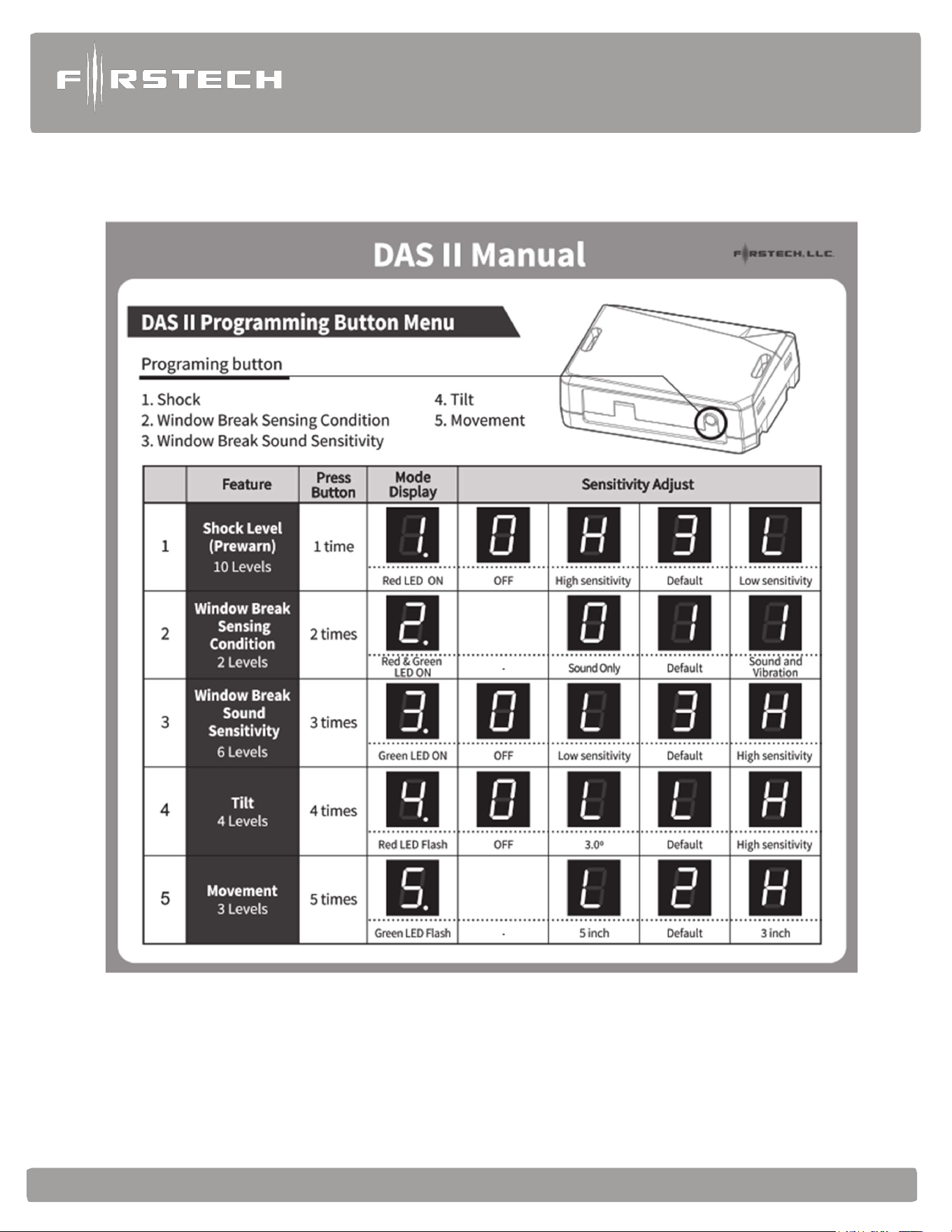
FT-DAS-II (Digital Adjustable Sensor gen II) (CM900AS only)
The DAS-II includes a dual stage impact sensor, and auto adjusting tilt sensor, and glass break sensor all in
one. Follow the steps below to properly setup your DAS II sensor levels. You can view our programming/
demonstration video located in our video library at https://www.youtube.com/c/myFirstech
DAS-II Programming Procedure
Installing Your DAS-II
NOTE 1: Make sure Option 4-12 is set to the DAS option.
NOTE 2: Connect cable to the red 4 pin port on the CM900AS.
NOTE 3: Mount DAS securely using zip ties or included hardware
Sensor can be mounted in any orientation; tilt will set 30 seconds after arming.
STEP 1: Turn the ignition to the ‘on’ position
STEP 2: Send Unlock command 2 times (unlock => unlock) using any Firstech remote or OEM
remote (capable of Controlling the CM900 through data module) At this time the DAS-
II display will initialize and stay powered up for at least 5 minutes or until ignition is off.
STEP 3: Push the programming button repeatedly until the desired sensor has been selected 1-5
shown in the table below. (The programming button will be used to navigate the sensor
adjustments and sensitivity once a sensor has been selected.)
STEP 4: Once the sensor has been selected hold the programming button for 2 seconds to
confirm selection and enter sensitivity adjustment. The adjustment options will
now be accessible with default setting displayed. (sensitivity options will be
shown in table below.)
STEP 5: push the programming button repeatedly until desired sensitivity level is reached
(setting 0 will indicate sensor is OFF => except option 2 window break
sensor conditions)
STEP 6: Hold programming button for 2 seconds to save sensitivity setting. After the
setting is saved the sensor will start over at sensor 1 again. (if the programming
button is not pressed within 5 seconds after setting the LED will flash 2 times
save the setting and exit that sensor programming)
STEP 7: Turn ignition off to exit programming
STEP 8: You are now ready to test the DAS
Alarm
and
Starter
System
www
.firstechdata.com
CM900
Master
Guide
Copyright 2022 Firstech , LLC. “Talk to me Goose…
”
Page
11

Alarm
and
Starter
System
www
.firstechdata.com
CM900
Master
Guide
Copyright 2022 Firstech , LLC. “Talk to me Goose…
”
Page
12
Optional DAS-II Shock Sensitivity setting Procedure (CM900AS ONLY)
NOTE 1: Make sure Option 4-12 is set to the DAS option.
NOTE 2: Connect cable to the red 4 pin port on the CM900AS.
NOTE 3: Mount DAS securely using zip ties or included hardware
Sensor can be mounted in any orientation; tilt will set 30 seconds after arming.
STEP 1: Turn the ignition to the ‘on’ position.
STEP 2: 2 Way remotes-hold buttons 1 and 2 (Lock and Unlock) for 2.5 seconds. You will get two
parking light flashes. 1 Way remotes-hold Lock and Unlock for 2.5 seconds. You will get two parking
light flashes.
STEP 3: To set the Warn Away Zone 1, (2way LCD) tap lock or button I. (1 Way) tap Lock. After you
get one parking light flash, proceed with impact testing on the vehicle. Note: please be careful as not to
damage the vehicle during the sensitivity adjustments. You will get siren chirps 1-most sensitive
(lightest impact to the vehicle requiring the least amount of force to trigger warn away) through 10-
least sensitive (heaviest impact to the vehicle requiring more force to trigger warn away). This sets
the impact sensitivity of Warn Away Zone 1. Setting Zone 1 will automatically set Zone 2. If you
would like to manually set Zone 2 proceed:
To set Instant Trigger Zone 2
a. Repeat Steps 1 and 2
b. Tap the Unlock button on your Firstech remote, the parking lights will flash 2 times.
c. After you get two parking light flashes, tap the vehicle. You will get siren chirps 1-most
sensitive through 10-least sensitive. This sets the impact sensitivity of Instant Trigger Zone 2.
STEP 4: Once you get two parking light flashes, you are ready to test your DASII.

Alarm
and
Starter
System
www
.firstechdata.com
CM900
Master
Guide
Copyright 2022 Firstech , LLC. “Talk to me Goose…
”
Page
13
Siren
We include the standard 6 tone mini siren with every remote start security (CM900AS) kit. We also offer 2
additional siren options 1. Mini Piezo (pain generator) 2. Battery backup siren with key. We have a variety
of siren feature options including length of output time, chirp output timing (i.e. when locking, unlocking,
or starting) so please make sure to set features 3-02 and 3-09 (CM900AS only) to desired options.
Thermistor (Temperature Sensor)
Every 2 Way LCD Firstech RF kit includes an optional thermistor, which must be plugged into the blue 2
pin port of the CM900 in order to use properly. The use of the thermistor allows the 2 Way LCD remote to
display the vehicle’s interior temperature on screen or the status page of your Drone mobile phone App. The
thermistor will also allow for the vehicle to start with timed hot or Cold starting; see features 2-05, 2-07 and
2-08 for the different options. We also offer temperature based Defrost options to activate the output
automatically Feature 3-13 and 3-14
Hood Pin
The hood pin switch triggers the alarm in the event the hood is opened while the alarm is armed. The hood
pin doubles as an important safety feature that prevents the remote start from engaging while the hood is
open.
Common Procedures
High Current Relay and Jumper settings
Caution: Jumper settings affect the polarity and use of certain outputs. If these jumpers are used
incorrectly,
damage to the vehicle and /or control module may occur.
Blue IGN 2 output wire: Jumper 2 (2nd Ignition / 2nd Starter / 2nd ACC)
Jumper 2 sets the behavior of the large blue wire on Connector 1. This wire is powered by an internal relay
in the control module. In the default position the jumper is set to 2nd Ignition. 2nd Ignition is common on
GM and Toyota vehicles and will need to be powered. You can change the behavior of the wire to act as a
2nd Starter or 2nd Parking light to power up those wires common on newer Toyotas and Nissans.
Green/White PRK Light output wire: Feature 1-06 (Parking Light, 2nd Starter, or (+) Trunk
Release)
Determines the output (not polarity) of the green/white wire on connector one (CN1). In the default position
it provides a positive (+) parking light output. Additional settings (including Positive (+) 2nd Starter, or
positive (+) trunk output) can be selected by changing feature 1-06 options.
Setting Auxiliary Outputs on Connector 2
You Must Have the OP500 Option Programmer
Setting auxiliary outputs on the control module involves the Programmable Output Connector wires
(POCs). Choose two POC wires that you are not using on I/O connector. For example, we will use POC 6
and POC 7.

Alarm
and
Starter
System
www
.firstechdata.com
CM900
Master
Guide
Copyright 2022 Firstech , LLC. “Talk to me Goose…
”
Page
14
STEP 1: Plug in OP500 and use the Right or Left Arrow Button to scroll through the menu to POC 6
or POC 7 on LCD Line 1.
STEP 2: Use the Up or Down Arrow Button to change the lower number on LCD Line 2 to 10 – Auxiliary
1 or 11- Auxiliary 2.
STEP 3: Scroll up the menu to Option 4-01 and 4-02 and set the options. Please see the Option Table for
details.
STEP 4: Our control modules have a secure auxiliary option 4-05. This requires you to tap the Start
Button before you tap the Trunk Button for Aux 1 or Hold Trunk + Start for 2.5 an then tap
Trunk for Aux 2. On 1-Way remotes you must hold the Trunk and Start Buttons for 2.5
seconds then tap the Trunk Button for Aux 1 or the Start Button for Aux 2. There are 2 other
options for this security override feature, please see feature table and descriptions for each
option
STEP 5: If you need to change the time settings of the outputs, scroll down to AU1 or AU2 on the
OP500. LCD Line 2 is the timed output. Note: with an OP500 update v.31 (www.
firstechdata.com) you will now be able to allow for timed AUX outputs of up to 15
minutes.
STEP 6: Hold the “W” Write button for 3 seconds to save all the changes.
FT-RFID
The FT-RFID function, now included with 2 of the latest 2-way remotes from Firstech, will
unlock/disarm the vehicle when in range of the antenna. In case where a proximity kit is being added to
an existing system (other than AM/AP) please see 2. install prep for RFID using the Gray data port
below.
1. Install prep for FT-RFID
STEP 1: Set Option 1-14 to Setting 1, option 2, or option 3 is “OFF” (option 4 is no longer available)
STEP 2: Connect ANT-2WSF using supplied 4 pin to 6 pin antenna cable.
STEP 3: ANT-2WSF mounting requirements will vary with the vehicle type. The proximity unlocking
range is approximately 3-6 ft from the antenna based on its mounting location.
Testing The FT-RFID
STEP 1: Make sure your FT remotes are programmed. AM/AP remotes will program to the 1W-AF
proximity antenna.
STEP 2: Enable the proximity unlock feature on your FT remote using the remote menu.

Alarm
and
Starter
System
www
.firstechdata.com
CM900
Master
Guide
Copyright 2022 Firstech , LLC. “Talk to me Goose…
”
Page
15
STEP 3: Proximity unlock/disarm - Once the CM has been locked/armed allow 15 seconds for the
RFID remote to unlock/disarm the system once its within proximity (approximately 3ft-6ft)
of the ANT-2WSF antenna. I.e. Arm the system wait 15 seconds walk up to the vehicle and
it will automatically unlock/disarm.
2. Install prep for FT-RFID using GRAY DATA port (remote programming sequence is the same)
STEP 1: Set Option 1-14 to Setting 1 or 2, or option 3 is “OFF”
STEP 2: Set feature 4 – 11 to option 2 (changes Gray port to support RFID antenna)
STEP 3: Connect the antenna using supplied 4 pin to 6 pin antenna cable, along with the short RF
to DATA adapter included with the RF kit, to the GRAY DATA PORT. If there is a
DRONE the RFID must use RF port, or upgrade to CMX
STEP 4: Antenna mounting requirements will vary with the vehicle type. The proximity unlocking
range is approximately 3-6 ft from the antenna based on its mounting location.
Testing The FT-RFID
STEP 1: Make sure your FT remotes are programmed (programming procedure will be the same)
AM/AP remotes will program to the 1W-AF proximity antenna.
STEP 2 : Proximity unlock/disarm - Once the CM has been locked/armed allow 15 seconds for the
RFID remote to unlock/disarm the system once its within proximity (approximately 3ft-
6ft) of the antenna. I.e. Arm the system wait 15 seconds walk up to the vehicle and it will
automatically unlock/disarm.
NOTE: For Passive Arming/Locking + RFID information please see feature 1-08 option 4
Tach Sensing
The default engine sensing mode is Tachless (voltage sense). In cold weather climates we recommend using
Tach sense for more reliable and consistent starting. The CM900 can be switched to tach mode automatically
by performing the following steps. Firstech recommends using a digital multimeter when testing for tach.
STEP 1: Test wire and make connection. At idle, the tach wire should test between 1 to 4 Volts AC.
As the vehicle RPM’s increase the voltage on the meter will also increase. Always make a wire to
wire connection for tach when hardwiring.

Alarm
and
Starter
System
www
.firstechdata.com
CM900
Master
Guide
Copyright 2022 Firstech , LLC. “Talk to me Goose…
”
Page
16
Number of
Parking
Light
Flashes
T
ach
Error
1
Option 2-10 is not in Tach setting
2
Key
is in the off
position
3
Bad tach signal. Find a different wire.
STEP 2: Start the vehicle with the key. Allow time for the engine to idle down. (If you do not want to wait
for the vehicle to idle down, you can shift the vehicle into reverse while holding your foot on the
brake.).
STEP 3: Learn tach: Activate
the remote start sequence by
holding the Start Button for 3
seconds. The parking lights will
flash once, and the siren will
chirp once to confirm a good
tach signal. If the parking lights
flash 2 times and the sirens
chirps twice, this
would indicate the tach did not learn. A few seconds after the 2 flashes, the CM900 will flash
parking lights to indicate the tach learn error.
“EZ TACH” programming procedure (only available when set to tach mode feature 2-10 option 2)
STEP 1: Hold the foot brake (must be held down before vehicle is on)
STEP 2: Start the vehicle (with foot brake still held down)
STEP 3: Wait 30 seconds (with foot brake still held down) for the CM to capture the engine running
tach signal. The CM will flash the parking lights 1 time after 30 seconds to indicate it has
captured a good tach or engine running signal. If there is no or poor signal the CM will flash
the standard tach programming diagnostics as shown above.
STEP 4: Programming complete (This procedure will be disabled after the first time but can be enabled
with a main control module power cycle)
Alternator Sensing
Alternator sensing is another method the remote start can utilize to determine if the engine is running. This is
different than the Tachless mode and a wire to wire connection must be made.
STEP 1: Change Option 2-10 to setting 3 - Alternator sensing.
STEP 2: Test wire and make connection. The stator wire is found at the vehicle’s alternator. Change your
multimeter to DC voltage before testing for this wire.
A. At rest, with the ignition off, the stator wire should test 0V DC.
B. Turn the ignition to the run position. The stator wire should now test between 4 – 6V DC.
C. Start the vehicle with the key. The stator wire should now test between 12 – 14V DC at idle.
STEP 3: Process complete – no further programming is required.
Tachless Mode – (Automatic Transmission Vehicles Only default setting for CM900S/AS)

Alarm
and
Starter
System
www
.firstechdata.com
CM900
Master
Guide
Copyright 2022 Firstech , LLC. “Talk to me Goose…
”
Page
17
Tachless sensing is an alternative engine sensing mode. It does not require a connection to the vehicle other
than the main ignition harness. Note: due to the delayed peak charging found with most late model
computer-controlled alternators, this feature may not be reliable.
STEP 1: Set Option 2-10 to setting 1 – Tachless Mode.
STEP 2: Process complete – there is no further programming required other than adjusting crank time
when necessary (see below).
Adjusting Crank Time: To adjust minimum crank times, refer to Option 2-12. To help ensure
successful starting, the system will automatically add additional crank time to the 2nd and 3rd start
attempts. In addition, there is a built in “Smart Resting Mode”. Traditional tach sensing is still highly
recommended for colder climates.
Timed Crank Setting – Automatic Transmissions Only
Option 2-10 setting 4 provides a timed 3 second crank for the remote start sequence. This option just
cranks the vehicle for 3 seconds and assumes remote start has completed. This option can be used for
GM and other vehicles with built in anti-grind systems.
Advanced Tachless
Advanced Tachless is a no connection feature (2-11 option 2) that can be used as a more reliable “Tachless”
or no wire connection option. In order for this feature work the no connection feature (2-10 option 1) must
be selected and no tach signal input on the main control module should be present.
Assumed Timed Crank
Assumed Time Crank is the last feature of Option 2-10 for remote starting. This is intended for vehicles with
built-in anti-grind feature or vehicles that do not have a 12V Positive starter wire at the ignition harness. This
option will send a 3.0 second crank signal to the vehicle. This option can be used on vehicles with built in anti-
grind systems or Push To Start (PTS) systems.
Alarm
and
Starter
System
www
.firstechdata.com
CM900
Master
Guide
Copyright 2022 Firstech , LLC. “Talk to me Goose…
”
Page
18
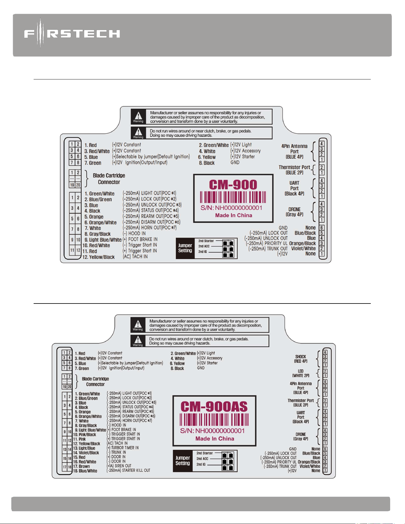
Wiring Descriptions
Connector 1 (CN1), 8-Pin (NOTE: Please see FT-LC1 for a low current version of CN1)
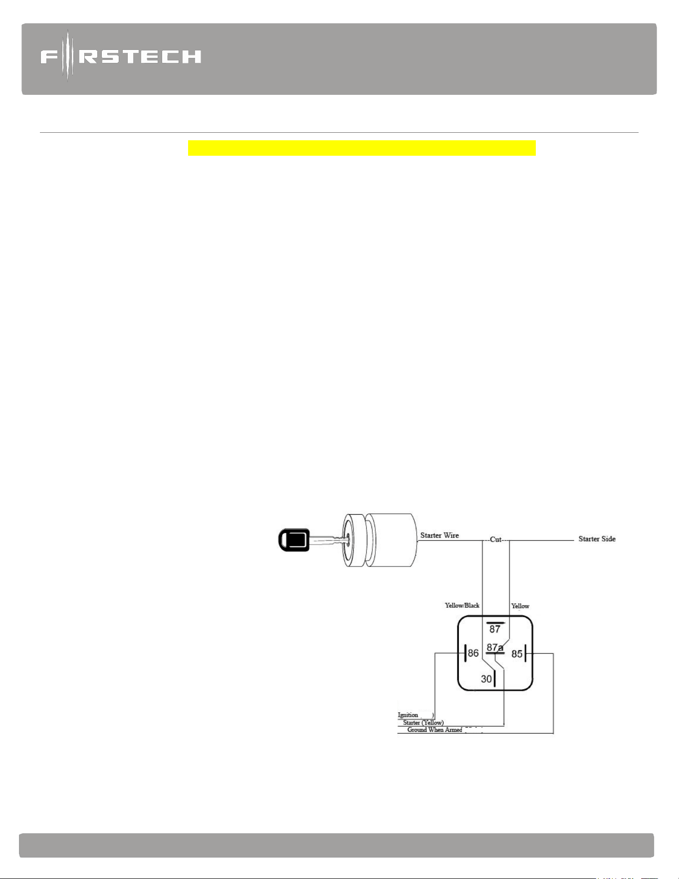
Pin 1 Red - Constant 12V positive (+) power input. (this input provides power to the CM processor, Ignition 1,
and accessory ports) This wire must be connected. The proper vehicle wire will test (+) 12V at all
times, even when the key is in the off position, on position, and during crank.
Pin 2 Green/White - Programmable Output: This positive (+) parking light wire triggers
when you lock, unlock, remote start, or during troubleshooting diagnostics. Note: This output is
programmable and can provide a 2nd starter or (+) trunk release output. This is achieved using
Jumpers located under the access door on top of the control module.
Pin 3 Red/White - Constant 12V positive (+) power input. This wire must be connected (this input provides
power for the accessory, starter, and parking light output). The proper vehicle wire will test (+) 12V at
all times - while the key is in the off position, the on position and during crank.
Pin 4 White - High Current Output: Accessory 12V positive (+) output (default). This wire must be
connected to the vehicle accessory / HVAC blower motor wire. The proper wire will test 0V with the key
in the off position, (+) 12V while key is in the on position, 0V while cranking and back to (+) 12V when
the key is returned to the on position.
Pin 5 Blue - Programmable Output: Positive 12V (+) output that powers up during remote start. This output
is programmable to provide a (+) 2nd ignition (default jumper setting), (+) 2
nd
Starter, or (+)
Accessory output using the jumpers located under the access door on top of the control module.
Pin 6 Yellow - Starter 12V positive (+)
output. This wire must be connected
for remote start. The proper wire
will test 0V with the key in the
off position, 0V while the key is
in the on position and (+) 12V
during crank. Note: You can use
the FT-ELOCK for starter kill
and anti-grind features. It can
be used to configure the starter
interrupt in various ways. We
provide a GWA (Ground When
Armed) output for standard
starter interrupt.

Alarm
and
Starter
System
www
.firstechdata.com
CM900
Master
Guide
Copyright 2022 Firstech , LLC. “Talk to me Goose…
”
Page
19
Pin 7 Green - Ignition 12V positive (+)
output and input. This wire must be connected to the vehicle’s
ignition for remote start and valet / remote programming. The proper wire will test 0V with the key in
the off position, 12 V (+) while the key is in the on position and 12V (+) during crank.
Pin 8 Black - Ground negative (-) input. This wire must be connected to the vehicle’s chassis ground. Make sure
no paint or rust is on the mounting surface. We recommend connecting this wire first. IF you’re having
trouble locating a good ground source you can use PIN # 4 at the Standard OBD II connection
Connector 2 (CN2), Black 20-Pin: Blade Connector
This connector is used only if you are installing a Blade-AL or Blade-TB. The wiring harness for this
connector only comes with the Blade cartridge. Please refer to the Blade install guide for wire description
http://compustar.idatalink.com.
Connector 3 (CN3) CM900AS (Remote Start + Alarm), Grey 18-Pin: Input/output harness (I/O harness)
IMPORTANT: Pins 1-7 are programmable for up to 19 different output types. Refer to Special Option
Group 2 for complete details. Note: These inputs/outputs are subject to change, for the latest software
update and feature table please visit compustar.idatalink.com or www.firstechdata.com
Pin 1 Green/White - (fixed output) Parking light 250mA negative (-) output. This will provide output whenever
the parking lights are activated for lock, unlock, remote start, diagnostics, and programming the proper
wire in the vehicle will test (-) when the parking light switch is in the on position.
Note: There are 18 additional POC setting options for this POC.
Pin 2 Blue/Lt. Green - [POC 2] Lock 250mA, 800mS (-) negative output: This is an optional output that
will provide only negative (-) output pulse for locking doors. System will lock doors and arm alarm.
IMPORTANT: You must reverse polarity for (+) trigger door lock systems using the FT-DM700, FT- DM600
or relays. For additional lock settings review Option Group 1.
Note: There are 18 additional POC setting options for this POC
Pin 3 Blue - [POC 3] Unlock 250mA, 800mS (-) negative output: This is an optional output that will provide only a
negative (-) output pulse for unlocking doors. System will unlock doors and disarm alarm. IMPORTANT:
You must reverse polarity for (+) trigger door lock systems using the FT-DM700, FT- DM600 or relays. For
additional lock settings review Option Group 1.
Note: There are 18 additional POC setting options for this POC
Pin 4 Black - [POC 4] Status/Ground while running (GWR) 250mA latched negative (-) output: This is an optional
output that will provide a latched negative (-) output 250mS before the ignition turns on, stays on throughout
the remote start duration and will be the last to shut off. This wire is most commonly used to trigger bypass /
transponder modules. Note: There are 18 additional POC setting options for this POC
Pin 5 Orange - [POC 5] Factory Alarm Arm (FAA) 250mA, 800mS negative (-) output: This is an optional output
that will provide a (-) pulse during lock, after crank and again after the remote start shuts down. The FAA
output timing can be configured using feature 1-05.
Note: There are 18 additional POC setting options for this POC

Alarm
and
Starter
System
www
.firstechdata.com
CM900
Master
Guide
Copyright 2022 Firstech , LLC. “Talk to me Goose…
”
Page
20
Pin 6 Orange/White - [POC 6] Factory Alarm Disarm (FAD) 250mA, 800mS negative (-) output: This
output will provide a (-) pulse during unlock and every time prior to the GWR (ground when running:
aka. Status output) turning on during the remote start sequence. It is typically used to disarm factory
security systems. Note: There are 18 additional POC setting options for this POC
Pin 7 White - [POC 7] Horn:250mA negative (-) output. This is an optional output that will provide a fixed
30mS negative output when triggered by the remote(s). The output control is based on feature 3-08
option setting. Note: There are 18 additional POC setting options for this POC
Pin 8 Gray/Black - Hood Pin negative (-) (default setting) input: This input is a safety shut down and alarm
trigger. It prevents the vehicle from remote starting while the hood is open and triggers the alarm if the
hood is opened while the alarm is armed. You can connect this wire to the hood pin supplied with this
kit, or to a wire in the vehicle that shows (-) only while the hood is open.
Pin 9 Light Blue/White - Brake 12V positive (+) input: This wire must be connected as it provides a
shut down for the remote start. It is also required to enter and exit Valet Mode. The proper wire will test
(+) 12V while the foot brake is pressed.
Pin 10 Pink/Black - Trigger start (-) input: This wire can be used to activate/deactivate the remote start
sequence when it receives a ground pulse based on feature 2-04 option setting 1, 2, or 3 pulses. There
are additional options for this Input please check feature 4-10
Pin 11 Pink - Positive (+) input: Trigger start which will activate/deactivate the remote start sequence when it
receives a positive or B+ pulse based on feature 2-04 option setting 1, 2, or 3 pulses is the default setting.
This can be done with a door lock motor output being operated by a factory keyless entry or another
external source. There are additional options for this Input please check feature 4-10
Pin 12 Yellow/Black - Engine sensing input (A/C): This wire is connected to the vehicle’s Tach or Alternator
wire and is required when using the tach and alternator sense setting. (You can also connect this wire
to the battery (+) post when using voltage sense to make it more accurate) IMPORTANT: To change
engine-sensing modes, you must change Option 2-10. Tach programming procedure can be found
on page 13.
Pin 13 Light Blue - Turbo Timer / Parking / Emergency brake (default setting) negative This input is required
for Turbo Timer mode. The proper e-brake wire will provide a (-) trigger when parking / emergency
brake is set, and the key is in the ignition or “on” position.
Pin 14 Violet/Black - Trunk zone input: This is an optional input that will monitor when the vehicle’s trunk has
been opened. The proper wire will provide a (-) trigger while the trunk is open.
Pin 15 Red - Door zone input (+): This wire monitors positive (+) trigger door-pins for security and turbo timer
purposes. The proper wire in the vehicle, will provide a (+) trigger only when the doors are opened. You
will need to test the wire for correct polarity.

Alarm
and
Starter
System
www
.firstechdata.com
CM900
Master
Guide
Copyright 2022 Firstech , LLC. “Talk to me Goose…
”
Page
21
Pin 16 Red/White - Door zone input (-): This wire monitors negative (-) trigger door-pins for security and turbo
timer purposes the proper wire in the vehicle, will provide a negative (-) trigger only when the doors are
opened. You will need to test the wire for correct polarity.
Pin 17 Brown - Siren: 600mA (+) output can be connected to the positive lead of an aftermarket siren. This
will produce output with arm/disarm, full alarm, and panic as a default setting. This can be changed
based on feature 3-09 option settings. The length of output for the arm/disarm chirps can be
changed using feature 3-02 settings.
Pin 18 Blue/white - Starter Kill: 250mA latched negative (-) output when armed and during remote start
(while running) that can be used with an FT E-LOCK to interrupt a starter wire protecting from
theft or grinding the starter during take over. Caution: If this wire is being used to trigger multiple
aftermarket accessories it must be diode isolated for each one.
Connector 3 (CN3) CM900S (Remote Start ONLY) White 12 pin Input / Output harness (I/O harness)
Pin 1 Green/White - Parking light 250mA negative (-) output. This will provide output whenever the parking
lights are activated for lock, unlock, remote start, diagnostics, and programming the proper wire in the
vehicle will test (-) when the parking light switch is in the on position.
Note: There are 18 additional POC setting options for this POC.
Pin 2 Blue/Lt. Green - [POC 2] Lock 250mA, 800mS (-) negative output: This is an optional output that
will provide only negative (-) output pulse for locking doors. System will lock doors and arm alarm.
IMPORTANT: You must reverse polarity for (+) trigger door lock systems using the FT-DM700, FT- DM600
or relays. For additional lock settings review Option Group 1.
Note: There are 18 additional POC setting options for this POC
Pin 3 Blue - [POC 3] Unlock 250mA, 800mS (-) negative output: This is an optional output that will provide only a
negative (-) output pulse for unlocking doors. System will unlock doors and disarm alarm. IMPORTANT:
You must reverse polarity for (+) trigger door lock systems using the FT-DM700, FT- DM600 or relays. For
additional lock settings review Option Group 1.
Note: There are 18 additional POC setting options for this POC
Pin 4 Black - [POC 4] Status/Ground while running (GWR) 250mA latched negative (-) output: This is an optional
output that will provide a latched negative (-) output 250mS before the ignition turns on, stays on throughout
the remote start duration and will be the last to shut off. This wire is most commonly used to trigger bypass /
transponder modules. Note: There are 18 additional POC setting options for this POC
Pin 5 Orange - [POC 5] Factory Alarm Arm (FAA) 250mA, 800mS negative (-) output: This is an optional output
that will provide a (-) pulse during lock, after crank and again after the remote start shuts down. The FAA
output timing can be configured using feature 1-05.
Note: There are 18 additional POC setting options for this POC

Alarm
and
Starter
System
www
.firstechdata.com
CM900
Master
Guide
Copyright 2022 Firstech , LLC. “Talk to me Goose…
”
Page
22
Pin 6 Orange/White - [POC 6] Factory Alarm Disarm (FAD) 250mA, 800mS negative (-) output: This
output will provide a (-) pulse during unlock and every time prior to the GWR (ground when running:
aka. Status output) turning on during the remote start sequence. It is typically used to disarm factory
security systems. Note: There are 18 additional POC setting options for this POC
Pin 7 White - [POC 7] Horn:250mA negative (-) output. This is an optional output that will provide a fixed
30mS negative output when triggered by the remote(s). The output control is based on feature 3-08
option setting. Note: There are 18 additional POC setting options for this POC
Pin 8 Gray/Black - Hood Pin negative (-) (default setting) input: This input is a safety shut down and alarm trigger.
It prevents the vehicle from remote starting while the hood is open and triggers the alarm if the hood is opened
while the alarm is armed. You can connect this wire to the hood pin supplied with this
kit, or to a wire in the vehicle that shows (-) only while the hood is open.
Pin 9 Light Blue/White - Brake 12V positive (+) input: This wire must be connected as it provides a
shut down for the remote start. It is also required to enter and exit Valet Mode. The proper wire will test
(+) 12V while the foot brake is pressed.
Pin 10 RED/White - Trigger start (-) input: This wire can be used to activate/deactivate the remote start sequence
when it receives a ground pulse based on feature 2-04 option setting 1, 2, or 3 pulses.
Pin 11 RED - Positive (+) input: Trigger start which will activate/deactivate the remote start sequence when it
receives a positive or B+ pulse based on feature 2-04 option setting 1, 2, or 3 pulses is the default setting.
This can be done with a door lock motor output being operated by a factory keyless entry or another
external source. There are additional options for this Input please check feature 4-10
Pin 12 Yellow/Black - Engine sensing input (A/C): This wire is connected to the vehicle’s Tach or Alternator wire
and is required when using the tach and alternator sense setting. (You can also connect this wire to the battery
(+) post when using voltage sense to make it more accurate) IMPORTANT: To change engine-sensing
modes, you must change Option 2-10. Tach programming procedure can be found on page 13.
Connector 4 (CN4), 6-Pin Note: This harness is not included with CM900 wire harness kits. The Lock (POC
2), Unlock (POC 3), Trunk release outputs have been moved to CN3 I/O harness and are
programmable outputs. This connector will still be available for any Firstech lock harness. (FT-DM600
or FT-DM700)
Pin 1 None - 12v B+ constant output: available when using a Firstech door lock Module DM600, DM700
Pin 2 Violet/White - Trunk release 250mA, 800mS negative (-) output: This is an optional output that will
release the trunk. Use CN1, Pin 2 if the vehicle is equipped with a (+) trunk release. System will unlock
doors and disarm alarm prior to trunk release.
Pin 3 Orange/Black - 2nd Unlock 250mA, 800mS negative (-) output: This is an optional output that will
provide a (-) pulse for driver’s priority door lock. IMPORTANT: You must isolate the driver’s door and
set feature 1-03 to option 2 (on).

Alarm
and
Starter
System
www
.firstechdata.com
CM900
Master
Guide
Copyright 2022 Firstech , LLC. “Talk to me Goose…
”
Page
23
Pin 4 Blue - Unlock 250mA, 800mS negative (-) output: This is an optional output that will provide a (-) pulse
for unlocking doors. System will unlock doors and disarm alarm. IMPORTANT: You must reverse
polarity for (+) trigger door lock systems. For additional lock settings review Option Group 1.
Pin 5 Blue/Black - Lock 250mA, 800mS (-) negative output: This is an optional output that will provide a (-)
pulse for locking doors. System will lock doors and arm alarm. IMPORTANT: You must reverse polarity
for (+) trigger door lock systems. For additional lock settings review Option Group 1. Pin 6 not used.
Pin 6 None - B- ground output: available when using a Firstech door lock Module FT-DM600, FT-DM700
Connector 5 (CN5), Grey 4 Pin (UART data port) Drone data to data.
Pin 1 (B+) - Constant 12V positive (+) output
Pin 2 (B-) - Ground (-) output
Pin 3 (RX) - Input, this wire receives data
Pin 4 (TX) - Output, this wire transmits data
Connector 6 (CN6), Black 4-Pin (RS 232 Data Port) ADS data to data
This connector is used for updating control modules via www.firstechdata.com. You must also use this port to
flash Blade bypass modules. This port provides simple connectivity iDatalink bypass modules.
Pin 1 (B+) - Constant 12V positive (+) output
Pin 2 (B-) - Ground (-) output
Pin 3 (RX) - Input, this wire receives data
Pin 4 (TX) - Output, this wire transmits data
Connector 7 (CN7), 2-Pin (Pre-wired Thermistor)
Plug optional thermistor into this connector to monitor the vehicle’s temperature. It used in conjunction with
Timer Start features along with displaying temperature on two-way LCD’s. To use Timer, Start features review
feature Group 2, and defrost features in feature group 3
Pin 1 Black - Thermistor
Pin 2 Black/White - Thermistor

Alarm
and
Starter
System
www
.firstechdata.com
CM900
Master
Guide
Copyright 2022 Firstech , LLC. “Talk to me Goose…
”
Page
24
Connector 8 (CN8), 4-Pin to 4-Pin or 4-Pin to 6-Pin (Pre-wired Antenna Cable)
Connect your antenna cable to this port. You can only use 4 to 4 pins or 4 to 6 pin antenna cables. 6 to 6
Pin antenna cables do not work. Do not use both Connector 9 and Connector 10 at the same time.
Pin 1 Yellow - RX input. This wire receives the signal from remote.
Pin 2 White - TX output. This wire transmits the signal to remote.
Pin 3 Red - Constant 12V positive (+) output.
Pin 4 Black - Ground
Connector 9 CM900AS ONLY (CN9), 2-Pin (Pre-wired LED) **WHITE connector Note: Do not mistake
for Thermistor port. Note: The LED will stay solid blue when armed for the duration of the sensor set up
time. (Approx. 25 seconds)
Pin 1 Black - L.E.D negative (-) ground.
Pin 2 Black/White- L.E.D. 2.5V positive (+) output.
Connector 10 CM900AS ONLY (CN10), 4-Pin (Pre-wired FT Shock Sensor)
Pin 1 Black - Negative (-) ground when armed (GWA).
Pin 2 White - 2nd stage negative (-) input. (Instant trigger)
Pin 3 Red - 12V positive (+) output.
Pin 4 Yellow - 1st stage negative (-) input. (Warn away)
Alarm
and
Starter
System
www
.firstechdata.com
CM900
Master
Guide
Copyright 2022 Firstech , LLC. “Talk to me Goose…
”
Page
25
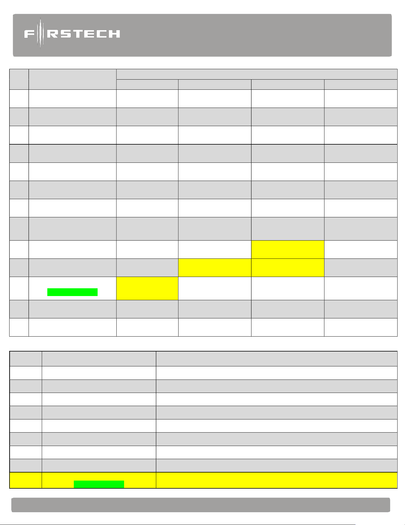
Feature Programming
T
ables
#1 Feature
Feature Group 1
Default(I) Option (II) Option (III) Option (IV)
1-1
Unlock before, Lock after,
starting.
Off On Lock After Start Only
Lock After Shutdown
Only
1-2
Lock / Unlock pulse
duration.
0.8 sec 2.5 sec 0.125 sec 3.5 sec
1-3 Driver's priority unlock Off On
1-4 Double pulse unlock. Off Unlock Lock Both Lock and Unlock
1-5 Rearm Output
1st Lock, After Start,
and After Shutdown
1st Lock, After
Shutdown
After Start Only After Shutdown Only
1-6
Parking light High Current
Relay
(+) Parking Light
Output 10A Max
(+) Starter Output 10A
Max
(+) Trunk Release 10A
Max
1-7
Unlock / Disarm with
Trunk Release
Unlock, Factory
Disarm,
and Trunk Release
Factory Disarm,
Trunk Release Only
Trunk Release Only
1-8
Passive Arming
CM900AS ONLY
Off
Passive locking
w/ Passive Arming
No Passive Locking
w/ Passive Arming
Passive locking/Arming
with RFID
1-9
Ignition controlled door
locks
Off On
RPM Locks
(MUST USE TACH)
1-10
Auto Relock
CM900AS ONLY
Off 30 sec 60 sec 5 min
1-11
Ignition / Accessory Out
Upon Unlock
Off
Ignition Pulse-same
timing as disarm pulse
Acc Pulse-same timing
as disarm pulse
Ig and Acc Pulse-same
timing as disarm pulse
1-12
RF sync by Datalink
Module
Off On
1-13 Double pulse Disarm Standard Double Pulse
1-14
FT-RFID Function Unlock once armed FTX/Always Unlock Off
N/A
1-15 Trunk Output Timing 1sec 2 sec 3 sec 4 sec
1-16
Siren/Horn Mute Control
on Remote
Disabled Enabled Silent Alarm
Alarm
and
Starter
System
www
.firstechdata.com
CM900
Master
Guide
Copyright 2022 Firstech , LLC. “Talk to me Goose…
”
Page
26
#2 Feature
Feature Group 2
Default(I) Option (II) Option (III) Option (IV)
2-1 Tach Sensing Type
Optimal Tach
Threshold
Previous Tach Method
2-2
Turbo mode.
CM900AS ONLY
Off 2 Min 1Min 4 Min
2-3 Diesel timer. Off 3~99 sec (12sec Default) 7 sec GM Ignition Delay
2-4 Trigger Start Off Single Pulse Double Pulse Triple Pulse
2-5
Cold or Hot Start
with Thermistor
Assembly
Off Cold start only Hot start only Cold and Hot start
2-6
Timer Start, or,
Minimum Interval
Between Cold Starts
3 Hour (4-minute
runtime,
double for Diesel)
2 Hour Repeat with Cold
Starting
of 2
-
8 (Runtime 2
-
7)
Reservation
(Runtime 2-7)
24 Hour Repeat with
Cold Starting 2-8
(Runtime 2
-
7)
2-7 Remote Start Runtime 15 Min 25 Min 45 Min
PROG. 3 ~ 45 mins
3 min (default)
2-8
Temperature of Cold
Starting
-10°C / 14°F -20°C / -4°F -5°C / 23°F
PROG. -30°C ~ 0°C / -
22°F ~ 32°F
(-15°C / 5°F default)
2-9
Temperature of Hot
Starting
25°C / 77°F 30°C / 86°F 35°C / 95°F
PROG. 20°C ~ 40°C /
68°F ~ 104°F
(40°C / 104°F default)
2-10 Engine Sensing
Tachless
no connection
Tach Alternator
No Connection
Assumed running
3.0sec
crank
2-11 Advanced Tachless Off On
2-12 Min. Crank Time Standard +0.2 Seconds to Crank Time +0.6 Sec to Crank Time Standard – MIN(0.2sec)
2-13 Timer Mode Off On
2-14
Turbo "set with"
CM900AS ONLY
(Parking Brake) is set
(Parking Brake): set
+ Hold start button for 2.5
sec
(Parking Brake): set →
Release → (within 7
seconds) set
2-15
Turbo "Start Timer”
CM900AS ONLY
Last door closed
(locks before shut
down)
Last door closed + Lock
command
10 Seconds After the
Last Door is Closed or
Lock Command
Last door
is closed
(Locks after shut down)
2-16
Shutdown by Door Open
after Remote Start
Off On
Alarm
and
Starter
System
www
.firstechdata.com
CM900
Master
Guide
Copyright 2022 Firstech , LLC. “Talk to me Goose…
”
Page
27
#3 Feature
Feature Group 3
Default(I) Option (II) Option (III) Option (IV)
3-1 Parking lights Control
Constant Output While
Remote Started
Flashing Output While
Remote Started
Off While Remote
Started
Off While Lock and
Unlock Only
3-2 Confirmation Chirps Medium (30mS) Short (15mS) Normal (60mS)
3-3
Dome Light Delay
CM900AS ONLY
Off 5 sec 45 sec Auto
3-4 Starter-Kill relay.
Anti-Grind + Starter
Kill
Anti-Grind
Anti-Grind + Passive
Starter Kill
3-7
Siren Duration (Upon
Alarm Trigger)
CM900AS ONLY
30 sec 60 sec 120 Sec Chirps for 20 seconds
3-06
Security features
CM900AS ONLY
On OFF Alarm ONLY
3-8 Horn Output On Double Lock Only On Lock and Unlock
On Lock, Unlock, and
Start
On Double Lock and
Start
3-9
SIREN Output
CM900AS ONLY
On Lock, Unlock, and
Start
On Double Lock Only On Lock and Unlock
On Double Lock and
Start
3-10 Valet procedure
Foot Brake + Ignition 5
times or Remote w/
Ignition is on
Foot Brake + Ignition 5
times or Remote
Wired Valet Input
3-13
Defroster Temperature
Control
Standard
Only below 32 degrees
F
PROG 0°C/32°F ~
13°C/55°F
below 6°C/42°F default
AUX 1
3-14 Defroster Output Timing 0.5 sec pulse 3 min latch 7 min latch
Constant Output Until
Remote Start Shuts
Down
3-15
Soft Disarm
CM900AS ONLY
Off On Disarm w/1 press
3-16 KP2 LED Flash
While Armed OFF While armed
3-17
Secure Start N/O Timer
CM900AS ONLY
Off 2 min 4 min
Prog. 1-10 min (10 min
default)
3-18
Secure Start N/C Timer
CM900AS ONLY
Off 1 min 2 min 4 min
Alarm
and
Starter
System
www
.firstechdata.com
CM900
Master
Guide
Copyright 2022 Firstech , LLC. “Talk to me Goose…
”
Page
28
#4 Feature
Feature Group 4
Default(I) Option (II) Option (III) Option (IV)
4-1 Aux 1 output 0.5sec Latch 0.5 sec Pulse + Program Program
4-2 Aux 2 output 0.5sec Latch 0.5 sec Pulse + Program Program
4-3 Aux 1 output Control By Remote Arm Disarm
4-4 Aux 2 output Control By Remote Arm Start
4-5
Secure Aux Output (1 and 2
Only)
On Off On While Armed
4-6 Hazard Output Timing 400mS 600mS 800mS 1000mS
4-7
Parking light interval during
remote start
10sec 20sec 40sec 60sec
4-8
Sliding door control, for use
w/iDatalink Modules
Off
Unlock, Factory Disarm,
and Sliding Door
Control
Factory Disarm and
Sliding Door Control
Only
4-10 (+/-) Trigger Start Input Trigger Start input Ignition input Valet Input Glow Plug Input
4-11 Gray Port function Drone AP RFID ANT KP2
4-12
Impact Sensor
CM900AS ONLY
FT Shock II
(Shock + Tilt)
DAS Sensor
1st Stage Disarm Input
| 2nd Stage Double Arm
Input
FT Shock.
4-14 Low Battery Warning OFF ON (at 11.7 Volts)
Low Battery Start
(11.7 V)
4-15 KP2 Sensitivity Normal High Low Lowest
S-#1 Feature Setting Value
1 AUX1 output time 1 ~ 99 [seconds], LA(Latch), 1~15 [minutes]
2 AUX2 output time 1 ~ 99 [seconds], LA(Latch), 1~15 [minutes]
3 Diesel timer 3 ~ 99 [seconds]
4 Remote Start Runtime
3 ~ 45 [minutes] (with OP500 update .31+
5 Cold Start Temperature -30 ~ 0 [°C] / -22 ~ 32 [°F]
6 Hot Start Temperature 20 ~ 40 [°C] / 68 ~ 104 [°F]
7 Defroster Temperature 0 ~ 13 [°C] / 32 ~ 55 [°F]
8 Assumed Running Crank time
1 ~ 6 [seconds] (with OP500 update .31+)
9
Secure Start Timer Prog.
CM900AS ONLY
1-10 minutes (with OP500 update .36)
Alarm
and
Starter
System
www
.firstechdata.com
CM900
Master
Guide
Copyright 2022 Firstech , LLC. “Talk to me Goose…
”
Page
29
S-#2
Feature Special Option Group 2 Setting Value
Programmable Output
Channel
Optional
1 POC #1 (Default: Light) 2nd LIGHT [ 1 ] HORN [ 8 ] Hazard light 2 [ 23 ] RAP [ 31 ]
2 POC #2 (Default: Lock)
2nd START [ 2 ] DOME LIGHT [ 9 ] Lock [ 25 ]
Secure Start N/O [32]
CM900AS ONLY
3 POC #3 (Default: Unlock)
2nd IG1 [ 3 ] Aux1 [ 10 ] Unlock [ 26 ]
Secure Start N/C [33]
CM900AS ONLY
4 POC #4 (Default: Status)
2nd ACC [ 4 ] Aux2 [ 11 ] Priority Unlock [ 27 ]
5 POC #5 (Default: Rearm)
STATUS [ 5 ] Defrost [ 17 ] Trunk Release [ 28 ]
6 POC #6 (Default: Disarm)
REARM [ 6 ] GWA [ 18 ] Starter Kill [ 29 ]
7 POC #7 (Default: Horn)
DISARM [ 7 ] Defrost-2 [ 21 ] Hazard light [ 30 ]

Alarm
and
Starter
System
www
.firstechdata.com
CM900
Master
Guide
Copyright 2022 Firstech , LLC. “Talk to me Goose…”
Page
30
Feature Option Descriptions
FO = Feature Option
1-01 Unlock before, Lock after:
FO1 - Off
FO2 - On: Sends an unlock command as soon as the remote start sequence is triggered then send a relock
command as soon as the CM900 has confirmed remote start success.
FO3 - Lock after start only: Sends a lock command after the CM900 has confirmed remote start
success.
FO4 - Lock after shutdown only: will send a lock command only after the CM900 has successfully
shut down. Note: It will not provide an output if the CM900 is shut down with an emergency override
input. (i.e. hood pin, or foot brake input)
1-02 Door Lock/Unlock output Pulse Duration: This does not affect the behavior of the factory arm output
(orange wire) or factory alarm disarm output (orange/white wire).
FO1 - 0.8 seconds: (-) Negative lock and unlock output time.
FO2 - 2.5 seconds: (-) Negative lock and unlock output time.
FO3 - 0.125 seconds: (-) Negative lock and unlock output time. This option may be helpful when using
lock/unlock to arm/disarm vehicles that may roll windows down with factory Arm/Disarm wires when
the standard output is too long.
FO4- 3.5 seconds: (-) Negative lock and unlock output time.
1-03 Driver’s Priority Unlock:
FO1 - Off: (default)
FO2 - On: This feature will allow the user to unlock the driver’s door first. If the unlock button is
pressed again within 4 seconds, the other doors will unlock. The driver’s door unlock must be isolated
from the other doors and use the blue (-) unlock. The Orange/Black (-) 2nd unlock (POC setting) is used
to provide unlock output to unlock all other doors.
1-04 Double Pulse Unlock:
FO1 - Off: (default)
FO2 - Unlock: This option will provide a double pulse output only for unlock each time the CM900
executes the unlock command. (Length of output time will be based on feature 1-02 option settings.)
FO3 - Lock: This option will provide a double pulse lock output only for lock each time the CM900
executes the lock command. (Length of output time will be based on feature 1-02 option settings.) FO4
- Lock and unlock: This option will provide a double pulse lock output for both lock and unlock each
time the CM900 executes lock or unlock commands. (Length of output time will be based on feature 1-
02 option settings.)
1-05 Rearm Output: Factory Alarm Arm (FAA) output function options
FO1 - After start, after shutdown, after first lock: This option triggers the FAA after every
successful remote start, every successful remote start shut down, and with every first lock command.
(First lock command is the first arm/lock command sent after the CM900 has been disarmed or
unlocked.)

Alarm
and
Starter
System
www
.firstechdata.com
CM900
Master
Guide
Copyright 2022 Firstech , LLC. “Talk to me Goose…”
Page
31
FO2 - After shut down only and first lock: This option triggers the FAA after every successful remote
start shut down, and with every first lock command. (First lock command is the first arm/lock command
sent after the CM900 has been disarmed or unlocked.)
FO3 - After Start only: This option triggers FAA after every successful remote start.
FO4 - After shutdown only: This option triggers the FAA after every successful remote start shut
down.
1-06 Parking Light Relay Output: High Current Onboard Relay that can be programmed to provide positive
(+) output based on the option selected. The default setting is Parking Light
FO1- Parking Light Output: This option will produce a positive output with remote programming,
tach programming, trunk release function, Lock/Arm Unlock/disarm, during remote start, full
alarm/panic, and while reporting diagnostics. This output will be disabled while in Valet mode.
FO2 – Starter 2 (+) Output: This option will produce a high current (+) starter 2 output (with the
same timing as starter 1) during the crank procedure.
FO3 – Trunk release (+) Output: This option will produce a high current (+) output when the trunk
release command is received.
1-07 Unlock / Disarm with Trunk Release:
FO1 - Unlock, Factory Alarm Disarm (FAD) trunk release: This option will send unlock and FAD
outputs prior to sending the Trunk release output. This applies to analog and data to data situations.
FO2 - Factory Alarm Disarm (FAD) with trunk release: This option will send the FAD output prior to
sending the trunk release output. This applies to analog and data to data situations.
FO3 - Trunk release only: This option will only send the trunk release output when triggered. This
applies to analog and data to data situations.
1-08 Passive Mode: CM900AS ONLY When options 2 or 3 are selected the user has the choice to activate
“Passive arming” feature using a Firstech remote or Drone (please check specific remote user ’s manual
for steps to activate passive)
FO1 - Off: (default)
FO2 - Passive locking with passive arming: This option when passive is activated will send lock/arm
outputs to lock/arm the CM900AS 30 seconds after the last zone is closed. The CM900AS will flash
the parking lights and chirp the siren 1 time every 10 seconds 3 times total as a warning that it is going
to Arm/lock itself.
FO3 - No lock output with Passive arm: This option, when passive arm feature is activated, will NOT
send the lock command one the CM900AS has passively armed itself. The CM900AS will flash the
parking lights and chirp the siren 1 time every 10 seconds 3 times total as a warning that it is going to arm
itself.
FO4 - “Passive Locking/Arming with RFID”: This option will allow the Passive locking with Passive
arming to LOCK/ARM the system 15 seconds after an RFID capable remote has left proximity of the
antenna. IF THE REMOTE IS WITHIN RANGE OF THE ANTENNA FOR 5 MINUTES OR
MORE, CM900AS WILL STOP THE PASSIVE ARMING SEQUENCE.
ANY ACTION FROM A FIRSTECH REMOTE, DRONE, KP SENSOR, IGNITION ON, OR
ZONE OPEN WILL AUTOMATICALLY RE-START THE PASSIVE ARMING SEQUENCE.

Alarm
and
Starter
System
www
.firstechdata.com
CM900
Master
Guide
Copyright 2022 Firstech , LLC. “Talk to me Goose…”
Page
32
1-09 Ignition Controlled Locks (DRIVE LOCK): When FO 2-4 are selected, the user can activate the “drive
lock” or ignition-controlled door locking feature using a Firstech remote or Drone. (Please check specific
remote user ’s manual for steps to activate Drive lock.)
FO1 - Off: (default)
FO2 - On: This option (when activated with the Firstech remote or Drone) will provide a door lock
output when the foot brake is applied, or 12 Volts is applied to the foot brake input on the CM900.
The CM900AS will also provide a door unlock output as soon as the key is turned off or the parking
brake is set (must have parking brake input connected or provide parking brake input from data
module)
FO3 - RPM locking: (Tach input is required for this option to operate properly.) This option will
provide a door lock output at approximately 20% RPM over the programmed idle tach output. (i.e.
program tach at 1000 rpm and doors will lock at a sustained 1200 rpm when moving.) The CM900AS
will also provide a door unlock output as soon as the key is turned off or the parking brake is set
(must have parking brake input connected or provide parking brake input from data module)
1-10 Auto Relock: CM900AS ONLY This Feature allows the CM900AS to relock the doors automatically if the
CM has been unlocked/disarmed but none of the input zones are opened.
FO1 - Off: (default)
FO2 - 30 seconds: This option allows the CM900AS to automatically relock/rearm 30 seconds after
CM900 has been disarmed/unlocked. This will only happen if no zones have not been opened.
FO3 - 60 seconds: This option allows the CM900AS to automatically relock/rearm 60 seconds after
CM900 has been disarmed/unlocked. This will only happen if no zones have not been opened.
FO4 - 5 minutes: This option allows the CM900AS to automatically relock/rearm 5 minutes after it has
been disarmed/unlocked. This will only happen if no zones have not been opened.
1-11 Ignition / Accessory Upon Unlock: This feature will provide an Ignition/Accessory output with unlock/disarm
command. (NOTE: will not provide pulse output with disarm before remote starting)
FO1 - Off: (default)
FO2 - Ignition (+) and (-) pulse output with disarm: This option will pulse both (+) and (-) ignition
wires upon unlock/disarm. Most new Ford vehicles require ignition pulsed + immobilizer with
unlock to disarm the factory alarm.
FO3 - Accessory (+) and (-) pulse output with disarm: This option will pulse both (+) and
(-) accessory wires upon unlock/disarm.
FO4 - Ignition (+) and (-) pulse and Accessory (+) and (-) pulse output with disarm: This option will
pulse both (+) and (-) ignition and accessory wires upon unlock/disarm. Some new Ford vehicles
require ignition and accessory pulsed + immobilizer with unlock to disarm the factory alarm.
Important: Also used in cases where the vehicle’s radio may turn on and stay on until the door is opened
when accessory is pulsed.
1-12 OEM Remote action updates for 2-way remote: This feature disables the arming, disarming, and
remote start confirmation updates to any Firstech 2 Way LCD when using an OEM remote.
FO1 - Off: (default) This feature disables the page back update to the 2 Way Firstech remote when your
interface module provides OEM remote status updates to the CM900.
FO2 - On:

Alarm
and
Starter
System
www
.firstechdata.com
CM900
Master
Guide
Copyright 2022 Firstech , LLC. “Talk to me Goose…”
Page
33
1-13 Double pulse disarm: This feature enables the FAD output. It will pulse 2 times with a single disarm
command.
FO1 - Off (default): Standard single pulse output on the FAD wire. (orange/white by default)
FO2 - On: This feature will generate a double pulse output on the FAD wire. (orange/white by
default)
1-14 FT- RFID Function: This feature covers the RFID unlock options. (Please refer to the FT-RFID
section of this manual for specific operation instructions and antenna mounting locations)
FO1 - Unlock “unlock once armed” (default): (The CM must be in an armed state for this option to
function) This option will enable the FT-RFID proximity unlock/disarm feature after activating with a
Firstech RFID enhanced remote. (Refer to the FT-RFID section of this manual for specific operating
instructions). The CM will be ready to send the disarm/unlock command 12-15 seconds after the system
has been armed using a Firstech remote or accessory (RPS, Drone, OEM remote input). Approximately
12 seconds after armed, the system will look for the RFID enhanced remote and disarm/unlock once the
remote enters the proximity field.
FO2 - FTX Unlock “always unlock”: This option will enable the FT-RFID proximity unlock feature
after activating with a Firstech RFID enhanced remote. The CM will always send the unlock/disarm
output when the remote enters/re-enters the proximity field regardless of the current state of the CM. (i.e.
armed/locked-disarmed/unlocked). Once the remote leaves the proximity field, it will be set to send the
unlock/disarm output as soon as it enters/re-enters. Note: because the ANT-2WSF antenna is always
searching for the remote, it will produce more current draw than the standard RFID unlock option 1.
FO3 – Off: No RFID functions are available by default.
1-15 Trunk Output Timing: This feature determines the length of output time for the (+) or (-) analog trunk
release wire.
FO1 - 1 Second: (default) Will provide a 250mA (-) negative output for 1 second on any POC that is
programmed for trunk release or setting 28.
FO2 - 2 Seconds: FO1- 1 Second: (default) will provide a 250mA (-) negative output for 2 seconds on
any POC that is programmed for trunk release or setting 28.
FO3 - 3 Seconds: FO1- 1 Second: (default) will provide a 250mA (-) negative output for 3 seconds on
any POC that is programmed for trunk release or setting 28.
FO4 - 4 Seconds: FO1- 1 Second: (default) will provide a 250mA (-) negative output for 4 seconds on
any POC that is programmed for trunk release or setting 28.
1-16 Siren/Horn mute control: this feature allows the installer to enable or disable the siren/horn mute control.
The mute feature will silence the siren or horn during arm, disarm, and start from the Firstech remote.
FO1 - Disabled: (default) will not allow for the Firstech remote to mute the siren or horn output.
FO2 - Enabled: this option will allow the end user to activate or deactivate the arm/disarm chirps using
a Firstech 4/5 button remote or DroneMobile.
2-01 Tach Sensing Method: This feature will determine the point at which the CM900 releases the starter
based on the sampled tach method.
FO1 - Optimal Tach reading: This option will allow the CM900 to sample the tach signal several
times during tach programming and select the optimal tach voltage at which to release the starter.

Alarm
and
Starter
System
www
.firstechdata.com
CM900
Master
Guide
Copyright 2022 Firstech , LLC. “Talk to me Goose…”
Page
34
FO2 - Previous tach reading: This option will set the CM900 to record the idle voltage which it is
being programmed. The CM900 will release the starter once the idle tach voltage is met.
2-02 Turbo Mode: (This feature requires door and e-brake input) NOTE: a door input must be connected
to allow Turbo Timer to continue to run after exiting the vehicle. This feature allows the user to
activate Turbo Timer Mode with their Firstech remote or accessory. This will keep the engine running
after removing the key for the specified time selected below. (Please check specific remote or
accessory user ’s manual for steps to activate Turbo Timer Mode)
FO1 - Off: (default)
FO2 - 2 Minutes: This option allows for a 2-minute run time after Turbo Mode has been engaged. To
engage, set the e-brake, remove key, exit vehicle, and lock with the Firstech remote or accessory.
FO3 - 1 minute: This option allows for a 1-minute run time after Turbo Mode has been engaged. To
engage, set the e-brake, remove key, exit vehicle, and lock with the Firstech remote or accessory.
FO4 - 4 minutes: This option allows for a 4-minute run time after Turbo Mode has been engaged. To
engage, set the e-brake, remove key, exit vehicle, and lock with the Firstech remote or accessory.
2-03 Diesel Timer: Note: OP500 required to adjust time from any of the default settings,
will show up as DISL on the top line of text when option 2 or 3 are enabled. This feature provides a
timed alternative solution to a hard-wired glow plug input to enable the CM900 to wait to start.
FO1 - Wire: (default) This option will allow the CM900 to read input on wait to start wire. It may be
connected to a wait to start indicator on a diesel vehicle. When the CM900 sees input, it will delay the
crank output for up to 99 seconds or until signal has been removed.
FO2 - Program (3-99 seconds): default setting is 12 seconds. This option allows the installer to adjust
the time in 1 second increments that the CM900 waits before cranking the starter.
FO3 - 7 seconds: This option offers a fixed 7 second delay before providing starter output.
FO4 - GM Ignition delay: This option is designed to delay the ignition output 250mS during the
remote start procedure. This allows for the accessory to output first, then ignition, to simulate normal
key starting. There are some vehicle models that may require this additional delay in order for it to
remote start properly.
2-04 Trigger to remote start: This feature changes the number of pulsed inputs (min of 60mS per pulse)
required to activate the remote start sequence using the trigger start input wire. (900AS Pink
wire/CM900S RED wire, pin 11, CN3). Note: If option 4 is selected and OEM remote control
feature is available through data, the Control Module will accept 3 OEM lock commands to
activate the start sequence.
FO1 - Off: (default)
FO2 - Single pulse: This option will trigger the remote start sequence with a single pulsed input to the
trigger start wire. This is ideal when adding accessories that can trigger the CM900.
FO3 - Double pulse: This option will trigger the remote start sequence with 2 pulses to the trigger start
input wire. This can be used when integrating with an OEM keyless entry remote.
FO4 - Triple pulse: (MUST BE USED WHEN 3X’s LOCK IS DESIRED) This option will trigger
the start sequence with 3 pulses to the trigger start input wire. This is ideal when trying to integrate the
OEM keyless entry remote. Note: this option will also allow the CM900 to accept a 3-pulse input from
OEM remote commands through data.

Alarm
and
Starter
System
www
.firstechdata.com
CM900
Master
Guide
Copyright 2022 Firstech , LLC. “Talk to me Goose…”
Page
35
2-05 Cold or Hot Start: Note: the Firstech thermistor temp sensor must be connected to the CM900 in
order to use these options. This feature turns on the cold/hot Timer start features.
FO1 - Off: (default)
FO2 - Cold start: This option enables the thermistor when using Timer Start Mode. It will start the car
at the preset cold temperature (see feature 2-08) according to the selected timer start option (see feature
2-06)
FO3 - Hot Start: This option enables the thermistor when using Timer Start Mode. It will start the car
at the preset hot temperature (see feature 2-09) according to the selected timer start option. (see feature
2-06)
FO4 - Cold and Hot start: This option enables the thermistor when using Timer Start Mode. It will
start the car at the preset Cold and Hot temperature (see features 2-08 and 2-09) according to the
selected timer start option (see feature 2-06)
2-06 Timer Start: This feature is designed to allow the user to have the CM900 automatically remote start
at the end of a selected timed cycle. It also be controlled by the thermistor, or a selected time by 2 way
remote, so it will start at a specified temperature at the end of the timed cycle or a specific time.
FO1 - 3-hour cycle: (4-minute runtime, 8-minute runtime for diesel) Once Timer Mode is enabled (see
feature 2-13) the CM900 will wait 3 hours, remote start and run for 4 minutes unless the cold start
feature is enabled. If this is the case, the CM900 will check the temperature once every 3 hours. If it is
at or below the selected temperature, (see feature 2-08) it will start and run for 4 minutes.
The same procedure will apply to the hot start feature. If there is any interaction with the CM900 after
timer mode has been activated using the Firstech remote or accessory, timer mode will be cancelled
and must be re-started to start a new timed cycle.
FO2 - 2 hour repeat with cold starting: (runtime based on feature 2-07 option setting and cold start
setting based on feature 2-08) Note: 2-way LCD remote required. This option is designed to monitor
the temperature 2 hrs. After timer mode is set and start if it is at or below the preset cold
start temperature (see feature 2-08). This process will continue until the user manually starts or remote
starts the vehicle.
FO3 - Reserve runtime: (runtime based on feature 2-07 option setting) Note: 2-way LCD remote
required. This option will allow the user to set a predetermined time to remote start on the 2 ways
LCD remote. Once the timer mode is activated it will start the countdown timer on the CM900 based on
the difference of time between what the remote clock is set to and the timer mode time is set to. (NOTE:
Must be a minimum of 20 minutes from current time displayed on the remote.)
I.e. remote time reads 7:00pm and timer mode time is set to 7:00 am the CM900 will activate the timer
mode to go for 12hours before it starts. Note: it is important that the remote time is as accurate as
possible when activating the timer mode to ensure that it will start at the desired time. If there is any
interaction with the vehicle or system after timer mode has been activated, it will cancel the timer.
FO4 - 24 hour repeat with cold starting: (runtime based on feature 2-07 option setting and cold start
setting based on feature 2-08) Note: 2-way LCD remote required. This option is designed to monitor
the temperature 24 hrs. After timer mode is set and start if it is at or below the preset cold
start temperature (see feature 2-08). This process will continue until the user manually starts or remote
starts the vehicle.

Alarm
and
Starter
System
www
.firstechdata.com
CM900
Master
Guide
Copyright 2022 Firstech , LLC. “Talk to me Goose…”
Page
36
2-07 Remote Start Runtime: This feature consists of four different settings for the remote start run time.
FO1 - 15 minutes (default)
FO2 - 25 minutes
FO3 - 45 minutes
FO4 – 3-minute (default) PROGRAMABLE: 1-45 Minutes at 1 minute increments (using the
OP500 programmer with software v.30 or newer that can be found at www.firstechdata.com)
2-08 Cold start Temperature: This feature allows the user 4 different temperature settings for cold start
operation
FO1 - 14°F/-10°C: will activate the start sequence at the end of the time cycle (set by feature 2-06
option setting) if temperature is at or below this temperature.
FO2 - -4°F/-20°C: will activate the start sequence at the end of the time cycle (set by feature 2-06
option setting) if temperature is at or below this temperature.
FO3 - 23° F/-5° C: will activate the start sequence at the end of the time cycle (set by feature 2-06
option setting) if temperature is at or below this temperature.
FO4 - 5° F/-15° C (default) PROGRAMMABLE -30 ~ 0 [°C] / -22 ~ 32 [°F]: (using the OP500
programmer with software v.31 or newer that can be found at www.firstechdata.com) will
activate the start sequence at the end of the time cycle (set by feature 2-06 option setting) if
temperature is at or below this temperature.
2-09 Hot Start Temperature: This feature allows the user 4 different settings for hot start operation
FO1 - 77° F/25° C: will activate the start sequence at the end of the time cycle (set by feature 2-06
option setting) if temperature is at or above this temperature.
FO2 - 86° F/30° C: will activate the start sequence at the end of the time cycle (set by feature 2-06
option setting) if temperature is at or above this temperature.
FO3 - 95° F/35° C: will activate the start sequence at the end of the time cycle (set by feature 2-06
option setting) if temperature is at or above this temperature.
FO4 - 104° F/40° C (default) PROGRAMMABLE 20 ~ 65 [°C] / 68 ~ 150 [°F]: (using the OP500
programmer with software v.310 or newer that can be found at www.firstechdata.com) will
activate the start sequence at the end of the time cycle (set by feature 2-06 option setting) if
temperature is at or above this temperature.
2-10 Engine Sensing: This feature determines how the CM will monitor the state of the engine (running or
not running), release the starter output, and consider the vehicle running. We provide 4 options for
engine sensing methods
FO1 - Tachless Mode – (Automatic Transmission Vehicles Only)
Tachless sensing is an alternative engine sensing mode. It does not require a connection to the vehicle
other than the main ignition harness. Note: due to the delayed peak charging found with most late
model computer-controlled alternators, this feature may not be reliable.
FO2 - Tach: This option uses a hard-wired input (yellow/black CN3 connector) or data signal from a
compatible interface module to read the vehicles RPM’s to release the starter during the remote start
process and determine that the engine is running.

Alarm
and
Starter
System
www
.firstechdata.com
CM900
Master
Guide
Copyright 2022 Firstech , LLC. “Talk to me Goose…”
Page
37
FO3 - Alternator: This option uses the hardwired tach input (yellow/black CN4 gray connector) to
read the voltage output from the vehicles stator wire to release the starter during the remote start
process and determine that the engine is running. Note: with late model computer-controlled
alternators, the peak charging voltage mat is not reached for several seconds after the vehicle is
running. This may make this option inconsistent when the battery is low or very cold.
FO4 - No Connection Assumed running: Note: can only be used with automatic transmission. This
option provides a programmable timed starter output (1-6 seconds) (programmability only
available with OP500 v.31+ update) (default to 3 seconds), then leave the rest of the CM ignition and
accessory outputs on and assuming the vehicle is running. Note: This is a good option for (PTS) Push
to Start applications and Hybrid vehicles (except manual transmission).
2-11 Advanced Tachless: This feature when used in conjunction with feature 2-10 option 1 will provide an
enhanced Tachless engine sensing mode.
FO1 - Off: (default)
FO2 - On: this option will enable the advanced algorithm. This option is better suited for late model
computer-controlled vehicles or older vehicles with poor battery conditions. Note: feature 2-10 must be
set to option 1 for it to work properly. If there is tach signal input to the CM900 either analog or data
interface module, this option will not operate consistently.
2-12 Crank Time: This feature allows the user to add or remove crank time to the selected option for feature
2-10 (engine sense).
FO1 - Standard: (default crank time no change).
FO2 - +200mS: To standard crank time of option selected on feature 2-10.
FO3 - +600mS: Adds 600 milliseconds to standard crank time of option selected on feature 2-10.
FO4 - (-)200mS: releases the starter output 200 Milliseconds earlier than standard crank time of option
selected on feature 2-10.
2-13 Timer Mode: (Note: Must be set to on to operate timer mode). This feature enables the user to activate
and deactivate Timer Mode (see option 2-06) using the Firstech remote or accessory (see the user
manual for that remote for instructions).
FO1 - Off: (default)
FO2 - On: user must still activate timer mode using their Firstech remote or accessory.
2-14 Turbo Timer activation “Activate with”: CM900AS ONLY
This feature will allow the user to customize the process used to activate the turbo timer feature Once
user has activated turbo timer feature, there is a 5-minute window to “Start Timer” the CM cancels
Turbo Timer feature. NOTE: a door input must be connected to allow Turbo Timer to continue to
run after exiting the vehicle.
FO1 – Parking/E-Brake set: When set to this option, when the CM sees the parking/E-Brake input
(analog or through data) it will activate the necessary ignition, accessory outputs and interface module,
to leave the vehicle running and activate Turbo Timer Mode.
FO2 – Parking/E-Brake set + Hold Start button for 2.5 seconds: When set to this option, the CM
will need Parking/E-Brake input (analog or through data) AND a start command from a remote (hold
start button for 2.5 seconds) to activate the necessary ignition, accessory outputs and interface module,
to leave the vehicle running and activate Turbo Timer Mode.

Alarm
and
Starter
System
www
.firstechdata.com
CM900
Master
Guide
Copyright 2022 Firstech , LLC. “Talk to me Goose…”
Page
38
FO3 – 2x’s Parking/E-Brake: (requires action) Set => Release => Set (within 7 seconds): When
set to this option, the CM will need Parking/E-Brake input (analog or through data) set then release
then set again within 7 seconds to activate the necessary ignition, accessory outputs and interface
module, to leave the vehicle running and activate Turbo Timer Mode.
2-15 Turbo Timer Mode “Start Timer”: CM900AS ONLY This feature will allow the user to customize the
process used to start the Turbo Timer.
FO1 – Last Door Closed (doors lock before shutting down): (default) (actions required within 5
minutes) This option will start the Turbo Timer once the last door/zone has closed and lock the doors a
few seconds BEFORE the timer ends and the engine shuts off. NOTE: a door input must be
connected to allow Turbo Timer to continue to run after exiting the vehicle.
FO2 – Last Door Closed AND LOCK command: (actions required within 5 minutes) This This
option will start the Turbo Timer once the last door/zone has close AND a LOCK command has been
sent. NOTE: a door input must be connected to allow Turbo Timer to continue to run after
exiting the vehicle.
FO3 – 10 seconds after the Last Door Closed OR LOCK command: (actions required within 5
minutes) This option will start the Turbo Timer 10 seconds after the last door/zone has close (allowing
the user to access other parts of the vehicle in case there are belongings that need to be removed
before the turbo time starts) OR after the last door is closed and a lock command is sent. NOTE: a
door input must be connected to allow Turbo Timer to continue to run after exiting the vehicle.
FO4 – Last Door Closed (doors lock after shutting down): (default) (actions required within 5
minutes) This option will start the Turbo Timer once the last door/zone has closed and lock the doors a
few seconds AFTER the timer ends and engine shuts off. (this can be used when the vehicles door will
not lock properly while the remote start is shutting down) NOTE: a door input must be connected to
allow Turbo Timer to continue to run after exiting the vehicle.
2-16 Force Remote Start shutdown: This feature will allow the user to have the remote start automatically shut
down as soon as there is a door zone opened.
FO1 – OFF (default)
FO2 – DOOR OPEN: This option will shut down the remote start0 when door zone is opened.
FO3 – With UNLOCK Command: This option will shut down the remote start when receiving an
unlock command. NOTE: If there is no unlock command or it fails the remote start will shut down with
door open.
3-01 Parking Lights while Remote Started: This feature changes the parking light behavior during remote
start.
FO1 - Constant output: This option will keep the parking light output (+ and -) on steady throughout
the entire runtime (runtime based on feature 2-07 selection)
FO2 - Flashing output: This option will flash the parking light output (+ and -) throughout the entire
runtime (runtime based on feature 2-07 selection)
FO3 - Off: This option turns the parking lights off while the vehicle is remote started.
FO4 - Off with lock and unlock only: This feature is designed to eliminate redundant parking light
flash with lock/unlock when interface module flashes the parking lights controlling the Factory
security. This will provide parking light output with remote start and troubleshooting diagnostics.

Alarm
and
Starter
System
www
.firstechdata.com
CM900
Master
Guide
Copyright 2022 Firstech , LLC. “Talk to me Goose…”
Page
39
3-02 Confirmation chirps: This feature will allow the user to select a shorter siren or horn output time to
simulate a quieter arm/disarm/start output.
FO1 - 30mS: This is a 30 millisecond siren output with arm, disarm, and start confirmation chirps. It
will produce a “medium” volume sound. (Softer than the standard 60mS output)
FO2 - 15mS: This is a 15-millisecond siren output with arm, disarm, and start confirmation chirps. It
will produce a “short” or quiet volume of sound. (Significantly softer than the standard 60mS output)
FO3 - 60mS: This is a standard 60 millisecond siren output with arm, disarm, and start confirmation
chirps.
3-03 Dome Light Delay: CM900AS ONLY This option is used when connecting the door trigger input to the
vehicles dome light circuit. It delays the door trigger input to prevent the door open icon displaying on
2 Way remotes upon lock/arm.
FO1- Off: (default)
FO2 - 5 seconds: This option will delay the door trigger input for 5 seconds when arming the system
to account for any vehicle dome light output delay.
FO3 - 45 seconds: This option will delay the door trigger input for 45 seconds when arming the system
to account for any vehicle dome light output delay.
FO4 - Auto: This option will allow the CM900AS to wait for a change in polarity on the door input
circuit, after the system has been armed, to monitor for security.
3-04 Starter-Kill: This option determines the operation of the GWA wire (CM900AS CN3 Pin 18 Blue/white
– CM900S must use a POC set to Starter kill option 29)
FO1 - Anti grind + Starter interrupt: this option will allow for the Starter Kill wire to provide a
negative output when the system is armed or remote started. This will enable a starter interrupt to
prevent the vehicle from being started with the key when in an armed state or grinding the starter
during a secure remote start take over.
FO2 - Anti Grind only: This option will allow the Starter Kill wire to provide a negative output when
the system is remote started which can be used to enable starter interrupt and prevent the user from
grinding the starter during secure remote start take over.
FO3 - Anti Grind and passive starter interrupt: This option will allow for Starter Kill wire to
provide a negative output when the system is remote started, or the passive starter interrupt is engaged.
This will prevent the user from grinding the starter during secure remote start take over, and enable
starter interrupt 45 seconds after the ignition has been turned off.
3-06 Security Features: CM900AS ONLY This feature will enable or disable the security features of the
CM900AS. Security features include sensor inputs, monitoring zone inputs while armed, horn, and siren
output. Basic features will function normally (lock, unlock, trunk release, remote start, parking lights.)
Please note the control module model when determining the correct feature option.
FO1 - On(default): This option enables the security features of the CM900AS allowing it to operate as a
remote start and security control module.
FO2 – Off: This option disables the security features of the CM900AS allowing it to operate as a remote
start only control module.
FO3 – Alarm Only: This option will disable the remote start function of the CM900AS allowing it to
operate as security only control module.

Alarm
and
Starter
System
www
.firstechdata.com
CM900
Master
Guide
Copyright 2022 Firstech , LLC. “Talk to me Goose…”
Page
40
3-07 Siren Duration: CM900AS ONLY This feature changes the duration of the siren during full alarm.
FO1 - 30 seconds: this option will provide 30 seconds of output (+) on the siren wire (brown CN3)
during full alarm.
FO2 - 60 seconds: this option will provide 60 seconds of output (+) on the siren wire (brown CN3)
during full alarm.
FO3 - 120 seconds: this option will provide 120 seconds of output (+) on the siren wire (brown
CN3) during full alarm.
FO4 - Chirps for 20 seconds: this option will provide 20 seconds of pulsed output (+) on the siren
wire (brown CN3) during full alarm.
3-08 Horn output: This feature controls the horn output behavior during Arm, Disarm, and Remote Start.
(POC 7 White wire or POC setting #8)
FO1 - On double lock only: (default) this option is designed to simulate a factory keyless entry
system by providing a horn output pulse (based on the option selection of feature 3-02) each time the
lock command is sent a second time within 8 seconds of the first lock command.
FO2 - On lock and Unlock only: this option will provide a horn output pulse (based on the option
selection of feature 3-02) with each lock or unlock confirmation.
FO3 - On lock, Unlock, and Start: this option will provide a horn output pulse (based on the option
selection of feature 3-02) with each lock, unlock, remote start command and remote started
confirmation.
FO4 - On double lock and Start: this option is designed to simulate a factory keyless entry system
by providing a horn output pulse (based on the option selection of feature 3-02) each time the lock
command is sent a second time within 8 seconds of the first. In addition, it will provide a horn output
pulse with remote start command and remote started confirmation.
3-09 Siren output: CM900AS ONLY This feature controls the siren (+) output behavior during Arm,
Disarm, and Remote
Start.
FO1 - On lock, Unlock, and Start: (default) this option will provide a (+) siren output pulse (based on
the option selection of feature 3-02) with each lock, unlock, remote start command and remote started
confirmation.
FO2 - On double lock only: This option is designed to simulate a factory keyless entry system by
providing a (+) siren output pulse (based on the option selection of feature 3-02) each time the lock
command is sent a second time within 8 seconds of the first lock command.
FO3 - On lock and Unlock only: this option will provide a (+) siren output pulse (based on the option
selection of feature 3-02) with each lock or unlock confirmation.
FO4 - On double lock and Start: this option is designed to simulate a factory keyless entry system
by providing a (+) siren output pulse (based on the option selection of feature 3-02) each time the lock
command is sent a second time within 8 seconds of the first. In addition, it will provide a (+) siren
output pulse with remote start command and remote started confirmation.

Alarm
and
Starter
System
www
.firstechdata.com
CM900
Master
Guide
Copyright 2022 Firstech , LLC. “Talk to me Goose…”
Page
41
3-10 Valet Mode: This feature will change the enter/exit valet mode procedure based on the option selected.
FO1 - Key 5 times with Foot Brake Trigger or Remote (Lock + Trunk) while Ignition is on: This
option allows the user to enter valet mode using either method described. Note: the user may exit valet
mode with their Firstech remote (please check users guide for each remote for valet mode exit
procedure), or with the key to ignition or “on” position
and press the foot brake 10 times within 10 seconds.
FO2 - Key 5 times with Foot Brake Trigger or Remote (Lock + Trunk): This option allows the
user to enter valet mode using either method described. Note: the user may exit valet mode with their
Firstech remote (please check users guide for each remote for valet mode exit procedure), or with
the key to ignition or “on” position and press the foot brake 10 times within 10 seconds.
FO3 – (+/-)Wired Valet Input: This option will allow a “Trigger Start” Input to be used as a wired Valet
mode enter/exit option. When this option is selected the previous Valet enter/exit options will no longer
work, except when using Drone Mobile.
This input will require (+/-) input for 5 seconds minimum, followed by 5 (+/-) input pulses to
enter/exit Valet mode. When Feature 3-10 is set to “wired valet input” option 1 WILL NO LONGER
FUNCTION
Either “Trigger Start” Input set to Valet Input can be connected to a momentary or latching toggle switch
mounted somewhere in the vehicle. NOTE: When using this option for security purposes, make sure the
switch is mounted in a discreet location, but it also must be accessible to the user.
3-13 Defrost output Temperature Control: This feature will determine the temperature at which the CM900
will provide an output on any POC programmed with setting 17 or 21 (defrost and defrost 2).
FO1 – Standard (activate with every start): (Default) this option will provide an output (length of
output based on feature 3-13 option settings) on any POC programmed with setting 17 (defrost) or 21
(defrost 2) every time with remote start confirmation.
FO2 - 32°F: (thermistor required) this option will provide an output on any POC programmed with
setting 17 (defrost) or 21 (defrost 2) with remote start confirmation on. This will happen if the temp
reading is at or below 32°F. (Length of output based on feature 3-13 option settings)
FO3 - 42°F (default) PROGRAMMABLE 0°C/32°F ~ 13°C/55°F: (thermistor required) this option
will provide an output on any POC programmed with setting 17 (defrost) or 21 (defrost 2) with remote
start confirmation on. This will happen if the temp reading is at or below 42°F (default temp) but can
be programmed up to 55°F (using the OP500 programmer with software v.30 or newer)
(Length of output for POC setting 17, based on feature 3-13 option settings)
FO4 – AUX 1: This option will allow the user to activate/deactivate the Defrost outputs using the AUX
1 function from any Firstech remote or DroneMobile. NOTE: This feature does not use an AUX
output
3-14 Defrost output Timing: This feature controls the output timing of POC setting 17, defrost. Note: POC
setting 21 defrost 2 is has a fixed pulsed output and is NOT affected by this feature.
FO1 - 500mS Pulse: This option will provide a 500 Millisecond pulsed output on any POC
programmed with setting 17 (Defrost) with timing based off feature 3-12 option setting.
FO2 - 3 minute latched: This option will provide a 3-minute latched output on any POC
programmed with setting 17 (Defrost) with timing based off feature 3-12 option setting. (This would be
good for any rear-view mirror defrost that may need a short-latched output time.)

Alarm
and
Starter
System
www
.firstechdata.com
CM900
Master
Guide
Copyright 2022 Firstech , LLC. “Talk to me Goose…”
Page
42
FO3 - 7 minute latched: This option will provide a 7-minute latched output on any POC programmed
with setting 17 (Defrost) with timing based off feature 3-12 option settings. (This would be good for
many front, rear, or rear-view mirror defrost functions that may need a longer latched output time.)
FO4 - Latched for entire runtime: (Remote start runtime based off feature 2-07 option setting) This
feature will provide a latched output for the entire remote start runtime on any POC programmed with
setting 17 (defrost) with timing based off feature 3-12 option settings. Caution: make sure not to latch
rear defrost functions on for too long as it may cause damage to the heating elements in the window.
3-15 Soft Disarm: this feature will enable Factory Alarm Arm (FAA) and Factory Alarm Disarm (FAD)
outputs to trigger when silencing the Compustar siren when sounding with full alarm.
FO1 - Off: (Default) this will keep the standard Compustar soft disarm operation. Soft disarm feature
allows the user to silence the Compustar siren as its sounding with full alarm without fully disarming
the system which may unlock the doors and leave the vehicle unsecure.
FO2 - On: this option will provide a FAD output on both data and analog connections, when the
user taps the unlock/disarm once to silence the Compustar system while it’s sounding, so it will disarm
any factory alarm that may be sounding as well. In case the FAD function unlocks the doors the
CM900 will send the FAA on both data and analog connections 5 seconds later to make sure the
vehicle is re-locked and secure. (This feature works well with GM, Chrysler, Dodge, Jeep, Toyota,
Lexus vehicles that may have factory security.)
FO3 – Disarm with 1 press: This option will allow the user to completely disarm the system once it is
sounding on the first unlock command. When set to this option the CM will unlock and send the FAD
commands on the first disarm/unlock press from a Firstech remote.
3-16 KP2: (Keyless entry window Sensor) this feature allows to disable the KP2 LED flash when armed.
FO1 – KP2: This option enables the latest Keyless entry paging window sensor KP2 function on the CM,
and flash the RED LED while armed.
FO2 – KP2 NO LED FLASH WHILE ARMED: This option enables the KP2 functions when using
the KP2 hardware with the CM, but the LED WILL NOT FLASH WHILE ARMED
3-17 Normally Open (N/O) Secure Start Output Timer CM900AS ONLY: Secure Start feature will
provide an output from any POC set to Secure Start N/O [32]. This output will send (-) 250mA for the
time selected by one of the options below.
It is designed to be used with our FTI SPTS (secure Push To Start) vehicle disable T harnesses. In its
rest state the vehicle disable harness will disable the PTS button until the driver is ready to use it.
NOTE: The Vehicle will not be able to go to ignition on until the system is disarmed/unlocked
Once the CM900AS is unlocked/disarmed the N/O output will energize the SPTS harness making the
PTS button available for use for the preselected time, or until the CM900AS is armed/locked. Once
Ignition on is detected the output will remain latched until Ignition has been turned off and the
preselected time has expired or the system has been armed/lock using a Firstech remote, Drone,
or KP sensor/
-NOTE: When using the N/O option be sure to select a timed output that will be most convenient
for your customer. IF the timer runs out, they MUST disarm/unlock again to re-activate the
Secure Start Output.

Alarm
and
Starter
System
www
.firstechdata.com
CM900
Master
Guide
Copyright 2022 Firstech , LLC. “Talk to me Goose…”
Page
43
-IF the user needs to disable the N/O secure start output for some reason, you can put the
CM900AS into Vale Mode. While in Valet mode the Secure Start Output will activate any time a
door is opened, (or when disarmed/unlocked) allowing the PTS button to function normally.
-The (+/-) Wired Valet Mode Input will need to be enabled to enter/exit Valet mode when using
the N/O Secure Start function. The open PTS button will not allow the vehicle to go to ignition on
position.
-NOTE: WE strongly recommend disabling the “OEM control of aftermarket security” function
when using an Idatalink interface with CM900AS. This will significantly increase the security of the
vehicle.
FO1 – OFF
FO2 – 2 min: once the system is disarmed/unlocked the PTS button will be fully functional for 2
minutes. IF the timer runs out the user must disarm/unlock again.
FO3 – 4 min: once the system is disarmed/unlocked the PTS button will be fully functional for 4
minutes. IF the timer runs out the user must disarm/unlock again.
FO4 – 10 min (PROG 1-10 min): once the system is disarmed/unlocked the PTS button will be fully
functional for 10 minutes. IF the timer runs out the user must disarm/unlock again. When set to
option 4 you may use an OP500 updated with OP500 v .36 (available for download at
Firstechdata.com) to change the timer between 1 and 10 minutes using 1-minute increments.
3-18 Normally Closed (N/C) Secure Start output Timer CM900AS ONLY: The N/C Secure Start feature
will provide an output from any POC set to Secure Start N/C [33]. This output will send (-) 250mA for
the period of time selected by one of the options below.
It is designed to be used with our FTI-SPTS (secure Push To Start) vehicle disable T harnesses. In its
active state the N/C option used with the vehicle disable harness will disable the PTS button ONLY
WHEN THE ALARM IS TRIGGERED, all other times there will be no output from the N/C POC,
and the PTS button will function normally.
-During an alarm event the N/C will disable the PTS button for the selected time to make sure any
additional attempts to “hack” or force start the vehicle will not work even after the siren output times
out. Once the CM900AS is unlocked/disarmed the N/C output will no longer function making the PTS
button operate normally.
-NOT RECOMMEDED WHEN USING N/O SECURE START FEATURE.
-IF the user needs to disable the N/C Secure Start Output completely they will need to enter valet mode.
FO1 – OFF
FO2 – 1 min: This will activate the N/C Secure Start output, disabling the PTS button the exact time of
an alarm event and continue to provide output for up to 1 minute or until system is disarmed.
FO3 – 2 min: This will activate the N/C Secure Start output, disabling the PTS button the exact time of
an alarm event and continue to provide output for up to 2 minutes or until system is disarmed.
FO4 – 4 min: This will activate the N/C Secure Start output, disabling the PTS button at the exact time
of an alarm event and continue to provide output for up to 4 minutes or until system is disarmed.

Alarm
and
Starter
System
www
.firstechdata.com
CM900
Master
Guide
Copyright 2022 Firstech , LLC. “Talk to me Goose…”
Page
44
4-01 Aux 1 Output: This feature determines the duration of the auxiliary 1 output. (Option 4 allows the
output duration to be set for a specific length of time 1-99 sec. and 1-15 min (with OP500 update only)
(Specific time setting only available when using the OP500)
FO1 - 500mS: This option will provide a (-) negative output for 500 milliseconds (Half second)
output on any POC programmed with setting 10 (AUX 1)
FO2 - Latched: This option will provide a latched (-) negative output on any POC programmed with
setting 10 (AUX 1). Note: This will stay latched until AUX 1 command is sent again to
shut it off.
FO3 - 500mS pulse + programmable timed output: this option will provide a (-) negative output for
500 milliseconds (0.5 seconds) output on any POC programmed with setting 10 (AUX
1). It will pause for 250 milliseconds then provide a timed output (based off feature 4-01 option
4). Note: to program the timed output, the user must change feature 4-01 to option 4, then adjust AU1
(AUX programmable output time) to desired time. To complete the programming steps, feature 4-01
must be changed to option 3. I.e. 0.5 second pulse…pause…10 second pulse, this option can be used to
roll windows up or down on a vehicle that requires a similar action using the driver’s door key
cylinder.
FO4 - Program: This option allows the AUX output time to be programmed for a duration between
1-99 seconds. Once selected the OP500 will display AU1 and below it will represent the time the
output will provide when triggered. Note: with an OP500 update to v.31 there will be additional time
duration between 1-15 minutes available.
4-02 Aux 2 Output: This feature determines the duration of the auxiliary 2 output. (Option 4 allows the
output duration to be set for a specific length of time 1-99 sec. and 1-15 min (with OP500 update only)
only available when using the OP500)
FO1 - 500mS: This option will provide a (-) negative output for 500 milliseconds (0.5 seconds)
output on any POC programmed with setting 11 (AUX 2)
FO2 - Latched: This option will provide a latched (-) negative output on any POC programmed with
setting 11 (AUX 2). Note: This latched output will reset when ignition is turned on.
FO3 - 500mS pulse + programmable timed output: this option will provide a (-) negative output for
500 milliseconds (0.5 seconds) output on any POC programmed with setting 11 (AUX
2). It will pause for 250 milliseconds then provide a timed output (based off feature 4-02 option 4).
Note: to program the timed output, the user must change feature 4-02 to option 4, then adjust AU2
(AUX programmable output time) to desired time. To complete the programming steps, feature 4-01
must be changed to option 3. (i.e. half second pulse…pause…10 second pulse) This option can be
used to roll windows up or down on a vehicle that requires a similar action using the driver ’s door
key cylinder.
FO4 - Program: This option allows the AUX output time to be programmed for a duration
between 1-99 seconds. Once selected the OP500 will display AU2 and below it will represent the time
the output will provide when triggered. Note: with an OP500 update to v.31 there will be additional
time duration between 1-15 minutes available.

Alarm
and
Starter
System
www
.firstechdata.com
CM900
Master
Guide
Copyright 2022 Firstech , LLC. “Talk to me Goose…”
Page
45
4-03 Aux 1 Output Control: This feature allows the user to configure the method of which Auxiliary 1 can
be activated.
FO1 - Remote: (default) This option allows AUX 1 (output time based on feature 4-01) to be triggered
by any 4 button Firstech remote or drone.
FO2 - With Arm: this option will trigger AUX 2 (output time based on feature 4-02) any time the
CM900 is locked/armed the first time (I.e. if you send a second lock/arm command it will not trigger
again)
FO3 - With Disarm: this option will trigger AUX 1 (output time based on feature 4-01) any time the
CM900 is unlocked/disarmed. Note: the system must be in the armed state when disarming to trigger
AUX 1. (I.e. if the vehicle is already in the unlocked/ disarmed state and you send a second
unlock/disarm command it will not trigger the output)
4-04 Aux 2 Output Control: This feature allows the user to configure the method of which Auxiliary 2 can be
activated.
FO1 - Remote: (default) this option allows AUX 2 (output time based on feature 4-02) to be triggered
by any 4 button Firstech remote or drone.
FO2 - With Arm: this option will trigger AUX 2 (output time based on feature 4-02) any time the
CM900 is locked/armed the first time (I.e. if you send a second lock/arm command it will not trigger
again)
FO3 - With Start: this option will trigger AUX 2 (output time based on feature 4-02) any time the
CM900 remote start sequence is activated. Note: this output timing will trigger at the same time as
GWR (status output)
4-06 Hazard Light output timing: Applicable to Hazard Light POC SV30 This feature offers optional time
interval between on and off pulses, to accommodate different hazard light timing.
FO1- 400mS(default): When using POC SV 30 the CMX will provide a negative output (on) to activate
the hazard light circuit. 400mS after the first output the CM will produce another output (off) to
deactivate the Hazard Light circuit. This should result in a single parking light flash, but if there are no
flashes or too many flashes you will have to try the other options.
FO2- 600mS: When using POC SV 30 the CMX will provide a negative output (on) to activate the
hazard light circuit. 600mS after the first output the CM will produce another output (off) to deactivate
the Hazard Light circuit. This should result in a single parking light flash, but if there are no flashes or too
many flashes you will have to try the other options.
FO3- 800mS: When using POC SV 30 the CMX will provide a negative output (on) to activate the
hazard light circuit. 800mS after the first output the CM will produce another output (off) to deactivate
the Hazard Light circuit. This should result in a single parking light flash, but if there are no flashes or too
many flashes you will have to try the other options.
FO4- 1000mS (1 sec): When using POC SV 30 the CMX will provide a negative output (on) to activate
the hazard light circuit. 1000mS after the first output the CM will produce another output (off) to
deactivate the Hazard Light circuit. This should result in a single parking light flash, but if there are no
flashes or too many flashes you will have to try the other options.

Alarm
and
Starter
System
www
.firstechdata.com
CM900
Master
Guide
Copyright 2022 Firstech , LLC. “Talk to me Goose…”
Page
46
4-07 Parking light flash interval: Applicable to Hazard Light POC SV23 and POC SV30. This feature offers
optional parking light flash intervals during remote start when using a Hazard Light output
FO1- 10 seconds (default): With this option the CM will generate one parking light flash during remote
start every 10 seconds.
FO2- 20 seconds: With this option the CM will generate one parking light output during remote start
every 20 seconds.
FO3- 40 seconds: With this option the CM will generate one parking light output during remote start
every 40 seconds.
FO4- 60 seconds (1 min): With this option the CM will generate one parking light output during remote
start every 60 seconds.
4-05 Secure Aux Output: this feature is designed to prevent accidental activation of the AUX outputs by
requiring an additional step when using any 4 buttons or 2-way LCD Firstech remote.
FO1- On: (default) this option will require the user to perform an additional step before activating
AUX output using any Firstech 4 button or 2-way LCD remote (2way remotes with Roman numeral
buttons will require a 0.5 second tap of button IV before activating any of the AUX outputs.2Way LCD
remotes with lock/unlock/trunk/start icons on the buttons use the start button for the same. 1way
remotes require the user to hold trunk + start buttons for 2.5 seconds before activating AUX outputs.)
FO2- Off: this option will disable the additional step required by the user to activate the AUX outputs.
FO3- On while armed: this feature will only require the user to perform the additional override step to
activate Aux outputs ONLY WHEN the CM900 is ARMED. While the system is disarmed or
unlocked this step is not required.
4-08 Sliding door control for datalink: This feature will provide an Unlock or Factory Alarm Disarm
(FAD) output when triggering the AUX control using iDatalink Modules (Sliding Doors)
FO1 - Off: (default) This option does not provide an unlock or a FAD output when activating AUX
output control using the iDatalink modules.
FO2 - Unlock and FAD: This option will provide unlock and a FAD output when activating AUX
output control using iDatalink modules.
FO3 - FAD only: This option will only provide a FAD (factory alarm disarms) output when activating
AUX output control using iDatalink modules.
4-10 Trigger Start Input (+/-): (PINK or PINK/Black wire CN3 CM900AS) (RED or Red/white wire
CN3 Pin 11 CM900S) Default to Trigger Start Input, this feature will determine the input function of
these 2 input wires
FO1 - Trigger start input: This option will enable to be used as a trigger for activating the remote
start function using a (+) pulse input on the positive input wire CN3 pin 11
FO2 – Ignition input: This option will enable the positive input wire CN3 pin 11 to be used as an (B+)
Ignition input only and be used for any application where ignition output is not required. Including
remote programming or Ignition controlled door locks
FO3 - (+/-) Wired Valet Input: this option allows either Trigger Start Inputs to be used as a wired
Valet Input. To enter/exit Valet mode using this input, it must see (+/-) for a minimum of 5 seconds,
then pulse the input 5 times. These wires can be used with a momentary or latching toggle switch to
enter/exit valet mode. When using valet mode for security purposes, make sure the switch is mounted
discreetly but is still accessible by the user

Alarm
and
Starter
System
www
.firstechdata.com
CM900
Master
Guide
Copyright 2022 Firstech , LLC. “Talk to me Goose…”
Page
47
FO4 - (+) Glow plug: this option will allow the positive input wire CN3 pin 11 to be used as a glow
plug delay or wait to start input. This is recommended for diesel vehicles that may have a positive
analog glow plug output available.
4-11 UART port 2: This feature will determine the communication protocol of the gray UART port.
FO1 - Drone: (default) This option will allow the grey UART port to communicate using the Drone
data protocol.
FO2 – AP_RFID: This option allows the grey UART port to support communication and remote
programming, with the ANT-1WAF RFID antenna. NOTE:MUST USE RF TO DATA ADAPTER
INCLUDED WITH RF KIT.
FO3 – KP2: This option will allow the gray UART data port to be used for KP2 (keyless window
sensor). NOTE:MUST USE KP TO DATA ADAPTER INCLUDED WITH KP2. In case of KP2
and Drone, the black UART data port may be used for DRONE.
4-12 Impact sensor: CM900AS ONLY This feature will determine the impact sensor input port function.
FO1 – FT SHOCK II: (default) This option will allow the CM900AS to support the new FT SHOCK
II which is comprised of the standard analog 2 stage impact sensor combined with a digital tilt sensor.
The FT SHOCK II impact sensitivity will be adjusted using the dial on the front of it, the dial can be
set from OFF to 1-10, with 1 being the LEAST sensitive and 10 being MAXIMUM sensitivity. The
digital tilt will be fixed at 2.5 degrees to trigger.
FO2 –DAS II: This option allows the impact sensor port to communicate with the DAS-II including
sensitivity programming and monitor any sensor output to the CM900AS.
FO3 - Arm/Disarm input: This option allows the impact sensor port (red) to be used as a CM900AS
arm/lock and disarm/unlock input. Note: the arm input requires 2 pulses to trigger arm/ lock and 1
pulse to disarm/unlock.
FO4 - Standard Shock: This option allows the CM900 to communicate with the FT-Shock analog
shock sensor. This impact sensor is manually adjustable on the sensor.
4-14 Low battery: This feature offers options to help alert the user of a low battery in the vehicle while the
CM is armed
FO1 - Off: (default) This option does not provide a low battery indication.
FO2 - On: This option will provide an alert to any Firstech 2 Way LCD remote or Drone when the
vehicle’s battery voltage (at the CM900 power connector) drops to 11.7volts for a minimum of 1
minute. Note: the Firstech 2-way LCD remote must be within range of the vehicle to receive the low
battery alert and this option must be set to receive low battery alerts to Drone.
FO3 - On + Start: This option will provide an alert to any Firstech 2 Way LCD remote or Drone
when the vehicles battery voltage (at the C900 power connector) drops to 11.7volts for a minimum of 1
minute. In addition to the alert the user can active the Timer mode (please refer to this manual for timer
mode feature description) to enable the low battery start function. Once the timer mode is active the
CM900 will adhere to the timer mode feature options selected but also monitor the vehicle battery
voltage which will override the timer mode and start at 11.7 volts.

Alarm
and
Starter
System
www
.firstechdata.com
CM900
Master
Guide
Copyright 2022 Firstech , LLC. “Talk to me Goose…”
Page
48
4-15 KP2 Sensitivity: This feature will allow the sensitivity for the KP2 keyless entry window sensor to be
adjusted to suit the conditions.
FO1 – Normal (default): This will be the standard sensitivity setting.
FO2 – High: This option is the most sensitive sensor setting.
FO3 – Low: This option will be lower sensitivity than the default standard setting.
FO4 – Lowest: This option will decrease the sensor sensitivity to its lowest setting.
Special Option Groups 1-2
IMPORTANT: The OP500 is required to change settings in Special Option Groups 1 and 2. Special
Option Group 1
SO1 - Aux 1 Output Timing: (Option 4-01 must first be set to setting 4.) This special option allows a
specific output duration for Aux 1 to be programmed 1-99 seconds. Note with OP500 update to
software v.30, latched output time 1-15 minutes are available for programming in addition to the
standard 1-99 seconds.
SO2 - Aux 2 Output Timing: (Option 4-02 must first be set to setting 4.) This special option allows a
specific output duration for Aux 2 to be programmed 1-99 seconds. Note with OP500 update to
software v.30, latched output time 1-15 minutes are available for programming in addition to the
standard 1-99 seconds.
SO3- Diesel Timer: (Option 2-03 must first be set to setting 2.) This special option allows a specific
wait to start time (in seconds) to be programmed. This prevents the need for a timer relay and
eliminates a connection to the “wait to start” wire.
SO4- Remote Start Runtime: (Feature 2-07 must first be set to option 4.) This special option allows a
custom Remote start time (in 1 minute increments up to 45 minutes) to be programmed. The default
runtime is 3 minutes.
SO5- Cold Start Temperature: (Feature 2-08 must first be set to option 4.) This special option allows
a specific temperature (in degrees F or degrees C based on OP500 software update v.30 V1 or V2) to
be set between -30 ~ 0 [°C] / -22 ~ 32 [°F] with a default temperature of -15°C / 5°F default for the
Cold Start Timer mode activation
SO6- Hot Start Temperature: (Feature 2-09 must first be set to option 4.) This special option allows
a specific temperature (in degrees F or degrees C based on OP500 software update v.30 V1 or V2) to
be set between 20°C ~ 40°C / 68°F ~ 104°F with a default temperature of 40°C / 104°F default the Hot
Start Timer Mode activation
SO7- Defrost Temperature: (Feature 3-13 must first be set to option 3.) This special option allows a
specific temperature (in degrees F or degrees C based on OP500 software update v.30 V1 or V2) to be
set between 0°C/32°F ~ 13°C/55°F with a default temperature of 6°C/42°F for the defrost activation.
SO8 – Assumed Crank output time: (feature 2-10 must be set to option 4). This special option
feature allows the start crank time output when using the Assumed running engine sense option to be
adjusted from 3 to 6 seconds in 1 second increments.

Alarm
and
Starter
System
www
.firstechdata.com
CM900
Master
Guide
Copyright 2022 Firstech , LLC. “Talk to me Goose…”
Page
49
Special Option Group 2
This special option group allows you to determine the output type of the POC wire you’re using. For
example, if you want to set POC #5 (default setting status out with setting value of 0) to Aux 1, you will
need change special option 5 to setting value 10. This must be done with the OP500.
POC 1 - Green/White • Parking Light Output: (default setting value 0) This channel will provide a
250mA (-) negative output when the CM900 parking lights output is generated (function also
POC setting 1)
POC 2 - Blue/Green • Lock: (default setting value 0) This channel will provide a 250mA output with
the lock/arm command. (function also POC setting 25)
POC 3 - Blue • Unlock: (default setting 0) This channel will provide a 250mA output with the
unlock/disarm command. (function also POC setting 26)
POC 4 - Black • GWR (ground when running aka status output): (default setting value 0) This
channel will provide a 250mA output with the remote start activation command and continue
to provide output until 100mS after the remote start process has shut own. (function also POC
setting 5)
POC 5 - Orange • FAA (Factory Alarm Arm): (default setting value 0) This channel will provide a
250mA output with the lock/arm command. Note: the CM900 will provide this output
approx.
100mS before the unlock output. (function also POC setting 6)
POC 6 - Orange/White • FAD (Factory Alarm Disarm): (default setting value 0) This channel will
provide a 250mA output with the unlock/disarm command. Note: the CM900 will provide this
output approx. 100mS before the unlock output. (function also POC setting 7)
POC 7 - White • Horn: (default setting) This channel will provide a 250mA output when Horn is
triggered. (function also POC setting 8)
POC setting value description (SV)
SV 0 – DEFAULT SETTING by wire
SV 1 - Parking light: provides a 250mA (-) negative parking light output on any POC programmed
with this setting.
SV 2 - Starter: provides a 250mA (-) negative starter output on any POC programmed with this setting.
SV 3 - Ignition: provides a 250mA (-) negative ignition output on any POC programmed with this
setting.
SV 4 - Accessory: provides a 250mA (-) negative accessory output on any POC programmed with this
setting.
SV 5 - GWR (status): provides a 250mA (-) negative while remote started on any POC programmed
with this setting. Can be used to activate interface modules during the remote start process.
SV 6 - FAA (Factory Alarm Arm): provides a 250mA, 800mS (-) negative output with the arm/lock
command on any POC programmed with this setting.
SV 7 - FAD (Factory Alarm Disarm): provides a 250mA, 800mS (-) negative output with the
disarm/unlock command on any POC programmed with this setting.
SV 8 - Horn: provides a 250mA (-) negative output with output control based on feature 3-08 option
setting when using any POC programmed with this setting.

Alarm
and
Starter
System
www
.firstechdata.com
CM900
Master
Guide
Copyright 2022 Firstech , LLC. “Talk to me Goose…”
Page
50
SV 9 - Dome light supervision: provides a 250mA (-) negative output with the disarm/unlock command,
on any POC programmed with this setting, for up to 45 seconds or until ignition is on.
SV 10 - AUX1: provides a 250mA (-) negative output (based on feature 4-01 setting) when AUX is
triggered by Firstech 4 button remote, 2way LCD remote, or Drone, on any POC programmed
with this setting.
SV 11 - AUX2: provides a 250mA (-) negative output (based on feature 4-02 setting) when AUX is
triggered by Firstech 4 button remote, 2way LCD remote, or Drone, on any POC programmed
with this setting.
SV 17 - Defrost: provides a 250mA (-) negative output (based on feature 3-13/3-14 settings) on any
POC programmed with this setting,
when defrost function has been activated (output time based on features 3-13 and 3-14 option
settings)
SV 18 - GWA (ground While Armed): provides a 250mA (-) negative output on any POC
programmed with this setting, while the system is armed or locked.
SV 21 - Defrost 2: provides a 250mA (-) negative pulsed output only on any POC programmed with
this setting, when the defrost output is engaged based on the temp setting of feature 3-13.
SV 23 – Hazard Light 2 Control: provides a 250mA (-) negative output on any POC programmed
with this setting that will produce a pulsed output allowing the CM to activate and then
deactivate a latching hazard switch. This will simulate parking light flashes in single flash
pulses. This output will also provide a pulsed parking light output during remote start
flashing 1 time every 10 seconds.
SV 25 - Lock: provides a 250mA, 800mS (-) negative output on any POC programmed with this
setting, with the lock/arm command.
SV 26 - Unlock: provides a 250mA, 800mS (-) negative output on any POC programmed with this
setting, with the unlock/disarm command.
SV 27 - 2nd Unlock: provides a 250mA, 800mS (-) negative output on any POC programmed with this
setting, when using the driver’s door priority feature. This wire would be used to unlock the
rest of the doors while unlock should be used to unlock the isolated driver’s door. Note: this
output can only be activated within 5 seconds after the first unlock command is sent.
SV 28 - Trunk release: provides a 250mA, 1 second (-) negative output (output timing based on feature
1-15 on any POC programmed with this setting, with the trunk release command.
SV 29 – Starter Kill: provides a 250mA (-) negative output on any POC programmed with this setting,
while the system is armed or locked, and during remote start for Anti-Grind.
SV 30 – Hazard Light Control: provides a 250mA (-) negative output on any POC programmed with
this setting that will produce a pulsed output allowing the CM to activate and then deactivate a
momentary hazard switch. This will simulate parking light flashes in single flash pulses.
This output will also provide a pulsed parking light output during remote start flashing
1 time every 10 seconds.
SV 31 – RAP Control: provides a 250mA-800mS (-) negative output on any POC programmed with
this setting that will produce a pulsed output:
-after every remote start shut down (manual, emergency, or runtime timeout)
-after ignition pulse when using feature 1-11 options 2, 3, or 4
Note: there will be no output pulse if ignition is present after remote start take over has
been completed

Alarm
and
Starter
System
www
.firstechdata.com
CM900
Master
Guide
Copyright 2022 Firstech , LLC. “Talk to me Goose…”
Page
51
Option Programming
How to Program Options
There are two ways to set options on the CM900 control modules. You can use the FT-OP500-KIT or most
Firstech remotes. The remotes include 4 or 5 buttons 1- and 2-Way remotes.
Option Programming Using the FT-OP500-KIT
The OP500 can be used to change anything in the Option Tables. It is required to change settings in Special
Option Groups 1 and 2.
STEP 1: Make sure system is unlocked/disarmed. Connect the antenna cable to the 4 or
6 pin ports on the top of the OP500. Once connected, the OP500 will power up if
CN1 or CN3 on the control module is connected properly.
STEP 2: Use the left or right arrow keys on the OP500 to select option. Use the up or down arrow
buttons to select the option setting. “1” is the default setting, “2”, “3”, and “4” are the
optional settings.
Special Option Group 1: Change the timed outputs of the various outputs.
Special Option Group 2: Change the Programmable Output Connections on the grey 20 pin
harness.
STEP 3: Hold the “W” (Write) button for 3 seconds. This finalize option changes to the control
module. Wait until OP500 displays “Success” before disconnecting.
To reset the options, hold the “R” (Reset) button and “W” (Write) buttons for 3 seconds.
Then hold the “W” button for 3 seconds.
Option Programming with FT-OP100 (valet button) (Limited feature group access 1-4)
STEP 1: Make sure the Control Module is in a disarmed/unlocked state
STEP 2: Connect FT Valet OP-100 button to the CM’s 4 pin blue antenna port
STEP 3: Go to Ignition on (without starting) + Foot brake input applied (in case of CM2305/CM900300
use door input in place of foot brake input)
STEP 4: Push the valet button 5 times holding it on the 5
th
time for the following time lengths to reach
the desired feature group:
1) 2 seconds → Option Group #1 (w/ light flash 1 time and siren/horn 1 chirp)
2) 4 seconds → Option Group #2 (w/ light flash 2 times and siren/horn 2 chirps)
3) 6 seconds → Option Group #3 (w/ light flash 3 times and siren/horn 3 chirps)
4) 8 seconds → Option Group #4 (w/ light flash 4 times and siren/horn 4 chirps)

Alarm
and
Starter
System
www
.firstechdata.com
CM900
Master
Guide
Copyright 2022 Firstech , LLC. “Talk to me Goose…”
Page
52
If you would like to reset all features to their default option setting push the valet button 10 times and hold
on the 10
th
time. Once complete, the parking lights will flash, and siren/horn will sound 5 times to
confirm reset.
STEP 5: Once the Option group has been selected release the programming button. Then push and release
the programming button again to select the feature number you wish to change. Once selected, wait for
the parking light flash, and siren/horn to sound confirming the feature number you’ve selected.
STEP 6: Once you have confirmed the feature you’ve selected push and release the valet button to select
the desired option. Once selected wait for the parking lights to flash and the siren/horn to sound confirming
the option you have selected.
STEP 7: Once finished turn ignition off, please test function to verify successful feature option change
Option Programming Using a Remote
Using a remote is a timed process so review this section before beginning. Options cannot be programmed
with 1 button remotes. IMPORTANT: Special Option Groups cannot be programmed with remotes – OP500
must be used.
STEP
1: Select the option you wish to program. (Use the corresponding table shown on the
following page
)
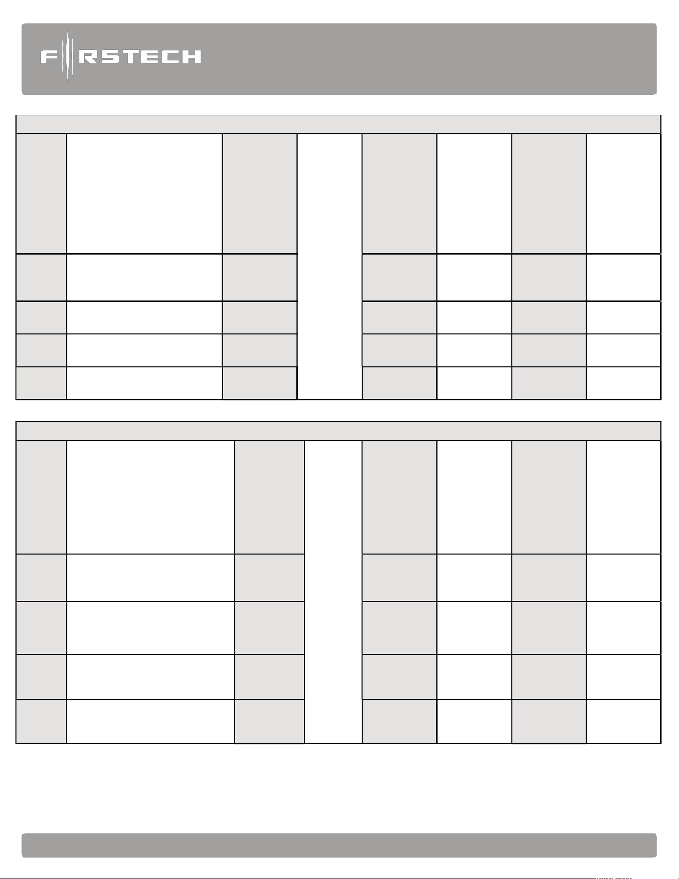
Alarm
and
Starter
System
www
.firstechdata.com
CM900
Master
Guide
Copyright 2022 Firstech , LLC. “Talk to me Goose…”
Page
53
How to Program Options with 5 Button 2-Way Remotes
Wait for chirp or park light
flash between each button
combination hold
To select a
feature
Wait for
flash
between
each tap
Wait for corresponding parking light flash
and/or siren chirp before selecting option
Select Option 1
Select Option 2
Select Option 3
Select Option 4
Option
Menu 1
(F + Trunk) for 3 seconds
then (F + Trunk) for 3
seconds
Tap Key
Button
Tap Lock
Button
Tap Unlock
Button
Tap Trunk
Button
Tap Key
Button
Option
Menu 2
(F + Trunk) for 3 seconds
then (F + Key) for 3 seconds
Tap Key
Button
Tap Lock
Button
Tap Unlock
Button
Tap Trunk
Button
Tap Key
Button
Option
Menu 3
(F + Key) for 3 seconds then
(F + Trunk) for 3 seconds
Tap Key
Button
Tap Lock
Button
Tap Unlock
Button
Tap Trunk
Button
Tap Key
Button
Option
Menu 4
(F + Key) for 3 seconds then
(F + Key) for 3 seconds
Tap Key
Button
Tap Lock
Button
Tap Unlock
Button
Tap Trunk
Button
Tap Key
Button
How to Program Options with 3 Button 2-Way Remotes
Wait for chirp or park light
flash between each button
combination hold
To select a
feature
Wait for
flash
between
each tap
Wait for corresponding parking light flash and/or
siren chirp before selecting option. i.e. feature 3 will
respond with 3 flashes
Select Option 1
Select Option 2
Select Option 3
Select Option 4
Option
Menu 1
(Lock + Unlock) for 3 sec
Then
(Lock + Unlock) for 3 sec
Tap Center
Button
Tap Lock
Button
Tap Unlock
Button
HOLD Unlock
for 2.5 sec
Tap Key
Button
Option
Menu 2
(Lock + Unlock) for 3 sec
Then
(Lock + Center button) for 3 sec
Tap Center
Button
Tap Lock
Button
Tap Unlock
Button
HOLD Unlock
for 2.5 sec
Tap Key
Button
Option
Menu 3
(Lock + Center button) for 3 sec
Then
(Lock + Unlock) for 3 sec
Tap Center
Button
Tap Lock
Button
Tap Unlock
Button
HOLD
Unlock
for 2.5 sec
Tap Key
Button
Option
Menu 4
(Lock + Center button) for 3 sec
Then
(Lock + Center button) for 3 sec
Tap Center
Button
Tap Lock
Button
Tap Unlock
Button
HOLD Unlock
for 2.5 sec
Tap Key
Button
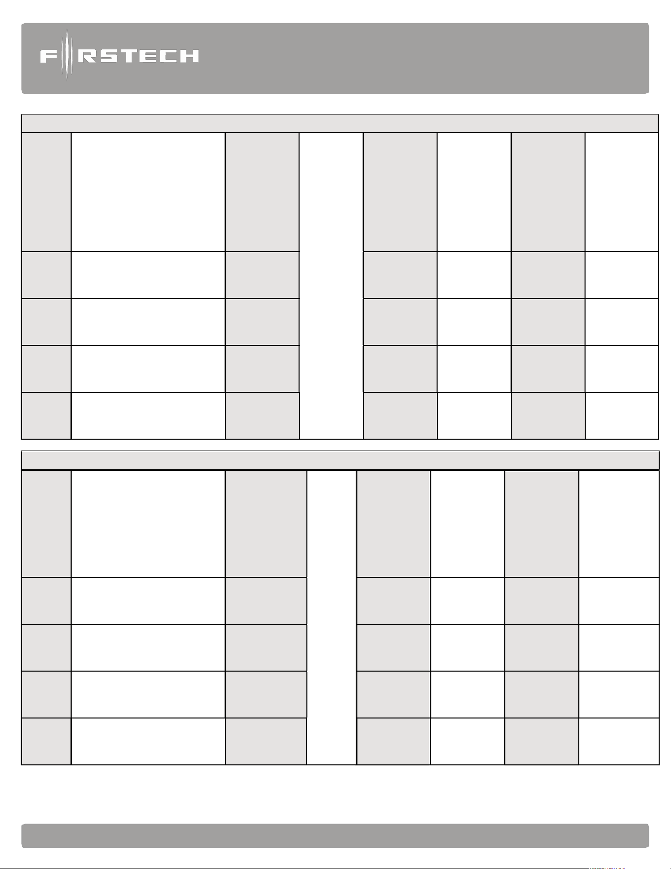
Alarm
and
Starter
System
www
.firstechdata.com
CM900
Master
Guide
Copyright 2022 Firstech , LLC. “Talk to me Goose…”
Page
54
or
siren
chirp
before
selecting
option
or
siren
chirp
before
selecting
option
How to Program Options with 4 button 2 Way Remotes
Wait for chirp or park light
flash between each button
combination hold
To select a
feature
Wait for
flash
between
each tap
Wait for corresponding parking light flash and/
Select Option 1
Select Option 2
Select Option 3
Select Option 4
Option
Menu 1
Lock + Unlock for 3 seconds
then Lock + Unlock for 3
seconds
Tap Key
Button
Tap Lock
Button
Tap Unlock
Button
Hold Trunk
Button for 3
seconds
Tap Key
Button
Option
Menu 2
Lock + Unlock for 3 seconds
then Lock + Key for
3 seconds
Tap Key
Button
Tap Lock
Button
Tap Unlock
Button
Hold Trunk
Button for 3
seconds
Tap Key
Button
Option
Menu 3
Lock + Key for 3 seconds
then Lock + Unlock for 3
seconds
Tap Key
Button
Tap Lock
Button
Tap Unlock
Button
Hold Trunk
Button for 3
seconds
Tap Key
Button
Option
Menu 4
Lock + Key for 3 seconds
then Lock + Key for 3
seconds
Tap Key
Button
Tap Lock
Button
Tap Unlock
Button
Hold Trunk
Button for 3
seconds
Tap Key
Button
How to Program Options With 4 button 1 Way Remotes
Wait for chirp or park
light flash between
each button
combination hold
To select a
feature
Wait for flash
between each tap
Wait for corresponding parking light flash and/
Select Option 1
Select Option 2
Select Option 3
Select Option 4
Option
Menu 1
Lock + Unlock for 3 seconds
then Lock + Unlock for 3
seconds
Hold Trunk
+ Key for 3
seconds
Tap Lock
Button
Tap Unlock
Button
Tap Key
Button
Hold Trunk
+ Key for 3
seconds
Option
Menu 2
Lock + Unlock for 3 seconds
then Lock + Key for
3 seconds
Hold Trunk
+ Key for 3
seconds
Tap Lock
Button
Tap Unlock
Button
Tap Key
Button
Hold Trunk
+ Key for 3
seconds
Option
Menu 3
Lock + Key for 3 seconds
then Lock + Unlock for 3
seconds
Hold Trunk
+ Key for 3
seconds
Tap Lock
Button
Tap Unlock
Button
Tap Key
Button
Hold Trunk
+ Key for 3
seconds
Option
Menu 4
Lock + Key for 3 seconds
then Lock + Key for 3
seconds
Hold Trunk
+ Key for 3
seconds
Tap Lock
Button
Tap Unlock
Button
Tap Key
Button
Hold Trunk
+ Key for 3
seconds

Alarm
and
Starter
System
www
.firstechdata.com
CM900
Master
Guide
Copyright 2022 Firstech , LLC. “Talk to me Goose…”
Page
55
STEP 2: Scroll through menu waiting for 1 parking light flash and/or siren chirp per line.
STEP 3: Once finished scrolling through menu, wait for the parking lights and/or siren chirp to confirm the
option number. i.e. option 2-04 will flash and/or chirp 4 times. Select your option using the Lock, Unlock,
Trunk, or Start buttons.
Resetting to Factory Defaults: To reset the options in a menu, enter the menu using your remote. To reset
options with a 2 Way remote, tap the Trunk button 3 three times. To reset options with a 1 Way remote, tap
the Key/Start button 3 times. Wait for parking lights to flash and/or siren chirp between each tap. After the
third tap, the menu will reset back to default. This must be done for each option menu that must be reset.
Alarm
and
Starter
System
www
.firstechdata.com
CM900
Master
Guide
Copyright 2022 Firstech , LLC. “Talk to me Goose…”
Page
56
Troubleshooting and Diagnostics
Remote Start Error Codes
If the remote start fails to start the vehicle, the parking lights will flash three times immediately. Following
those two flashes the parking lights will flash again corresponding to the error table below:
Number of
Parking Light
Flashes
Remote Start Error
1
Motor running or must program tach before 1st remote
start
2 Key in ignition on position
- N/A
5 Foot brake on
6 Hood open
- N/A
8 Tach or Tachless sensing failure
- N/A
10 System is in Valet Mode
2 Way remotes will display the error number “Start Err##” on the LCD.
Remote Start Shutdown Error Codes
If the remote start sequence has been completed and the vehicle shuts down, the vehicle’s parking lights
will flash 4 times, pause then flash again with the error code. Tap button 4 on 2 Way remotes to initiate the
shutdown error codes. On 1 Way remotes hold the Trunk and Start buttons together for 2.5 seconds.
Number of
Parking Light
Flashes
Remote Start Shutdown Error
1 Lost engine sensing signal (Tach/Alternator/Tachless)
2 Lost emergency brake signal (Manual Transmission)
3 Foot brake triggered
4 Hood pin triggered
Alarm
and
Starter
System
www
.firstechdata.com
CM900
Master
Guide
Copyright 2022 Firstech , LLC. “Talk to me Goose…”
Page
57
Alarm LED Diagnostics
When the alarm is triggered the LED on the RPS (if installed), Secure Valet (if installed) and the LED (if
installed) will flash a certain number of times as shown in the table below. This is intended for users with 1
Way remotes.
2 Flash
Door Input
3 Flash Shock stage 1
4 Flash
Shock stage 2
5 Flash
Tilt
6 Flash
Ignition on
7 Flash
Hood Input
8 Flash
Trunk Input
9 Flash
AUX sensor stage 1
10 Flash
AUX sensor stage 2
Frequently Asked Questions
I have everything hooked up and the system will not respond.
A: The remotes need to be programmed. Review the “Common Procedure” section of this manual.
When remote starting, the siren chirps 3 times and parking lights flash 3 then 1 time.
A: You must program tach before remote starting. Also, be sure to check the foot brake and ignition wires on
the CM900.
I am trying to program the control module with the OP500 Option Programmer, and it flashes
“ER 01” when I plug it in to the antenna cable. What should I do?
A: Make sure that the system is not locked/armed. The last thing to check is the antenna cable or antenna
extension cable – make sure this is not damaged. If you need to, try another cable. When the OP500 is
working properly, it will read “success good.”
Why doesn’t my CM900 have the green/white wire loop inside the brain module?
A: The CM900S/AS are for Automatic transmission vehicles ONLY.
What do I do with the thick blue wire on Connector 1?
A: It is used to power a (+) 2nd Ignition. You can also change the output via jumper within the control module. It can be
changed to power a (+) 2nd Accessory or (+) 2
nd
Starter.
I need a ground when armed wire, does the control module have one?
A: You can use pin 1-blue/white wire on the Grey Connector 5. You must cut this wire and place a diode in
line so that when the ignition on the other side of the relay goes to ground and it does not back feed to your
accessory. Install the stripe side of the diode facing the control module.
Does the CM900 series have Tachless mode?
A: Yes. The CM900S and CM900AS are default set for Tachless engine sense. For details, review the
“Common Procedures” section of this manual.

Alarm
and
Starter
System
www
.firstechdata.com
CM900
Master
Guide
Copyright 2022 Firstech , LLC. “Talk to me Goose…”
Page
58
All my connections are made, and remotes programmed, how do I program the tach?
A: Review the “Common Procedures” section of this manual. You must have your remotes programmed,
start your vehicle, then hold the remote start button. Vehicle should chirp and/or flash once if it programs,
three times if it does not like the tach source.
The vehicle will lock and unlock but will not remote start or flash the parking lights.
A: The system is in Valet Mode. Tap the Lock and Trunk Buttons for a half second to exit Valet Mode. You
can also turn the ignition ‘On ‘and press the foot brake 10 times within 10 seconds.
Whenever I try to arm the vehicle, it chirps the siren 3 times and will not arm.
A: Check the hood and trunk trigger inputs.
Do the door locks flip flop in polarity?
A: No. You can use the FT-DM700 relay pack for high current positive (+) locks, or the FT-DM600 harness
used for low current 600mA positive (+) locks.
What are Firmware Version Diagnostics?
A: When you turn the Ignition on and hold buttons 1 and 4 or Lock and Start for 2.5 seconds then the
parking lights will flash 1 time on the CM900 series showing V.1.
What is this cartridge slot on the CM900?
A: This is the slot for the Blade cartridge system. This slot is for the Idatalink Blade remote start bypass
modules. For more information on the compatibility and install information please visit www.compustar.
idatalink.com. Using this system eliminates many connections between your standard control module and
bypass module. IMPORTANT: If you are not using the Blade then you will not have or use the black 20 pin
connector on the control module.

Alarm
and
Starter
System
www
.firstechdata.com
CM900
Master
Guide
Copyright 2022 Firstech , LLC. “Talk to me Goose…”
Page
59
How do I take the system out of Valet Mode with a 1 Button Remote?
A: Turn the ignition on and tap the foot brake 10 times within 10 seconds.
Why are the ignition-controlled door locks option not working?
A. Check option 1-09. It should be set on 2 or 3. The option must also be turn on via the remote. On 2
Way LCD remotes tap the Lock and Start Buttons for a half second, the parking lights will flash once to show
the option is turned on. On 1 Way remotes tap the Lock and Start buttons for a half second.
The vehicle remote starts when disarmed, but not when armed.
A: The starter kill relay was installed backwards. Check to make sure the yellow/black wire is going to the
key side of the starter wire and that the yellow wire is going to the engine side.
The vehicle starts and shuts down 3 times in a row.
A: This usually means that the engine sensing mode is not working correctly. If you are using a coil, change to
an injector or try alternator sense mode.
On the brain, how do I set the auxiliaries?
A: You must have an Option Programmer (FT-OP500-KIT) to set the auxiliaries on the. First choose two POC
wires on CM that you are not using. With the OP500 go into the Special Option Group 2 and set those POC’s
to Aux 1 and Aux 2. Review the “Special Option Group” programming section of this manual.
Technical Support Contacts
Firstech technical support is reserved for authorized dealers only.
Monday - Friday: 888-820-3690
(6:00 am – 6:00 pm Pacific Standard Time)
Web: www.firstechdata.com
Wiring Diagrams
Go to www.firstechdata.com to access wiring info. If you are an authorized dealer and unable to access this
site please contact your sales rep or we call 888-820-3690 Monday through Friday, 7 am to 5 pm Pacific
Standard Time.

Alarm
and
Starter
System
www
.firstechdata.com
CM900
Master
Guide
Copyright 2022 Firstech , LLC. “Talk to me Goose…”
Page
60
Consumer site:
- https://www.compustar.com/
- http://www.dronemobile.com/
- https://accounts.dronemobile.com/userlogin
Product, Support, and Vehicle info:
Product manuals, tech tips, training aids:
- https://firstechdata.com/
Drone activation and testing:
- http://Install.myfirstech.com/
Tech Support page Facebook access:
-
https://www.facebook.com/groups/Firstechtechsupportgroup/?fref=nf
Operation and training videos
- https://www.youtube.com/channel/UCvLp0NC-DQnoPJVly7do5Kg
Dealer activation/flashing sites:
Drone activation account:
- https://install.myfirstech.com
Idatalink and Firstech flashing site:
- http://compustar.idatalink.com
- http://arcticstart.idatalink.com
- http://maestro.idatalink.com/

Alarm
and
Starter
System
www
.firstechdata.com
CM900
Master
Guide
Copyright 2022 Firstech , LLC. “Talk to me Goose…”
Page
61
NOTES: