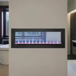
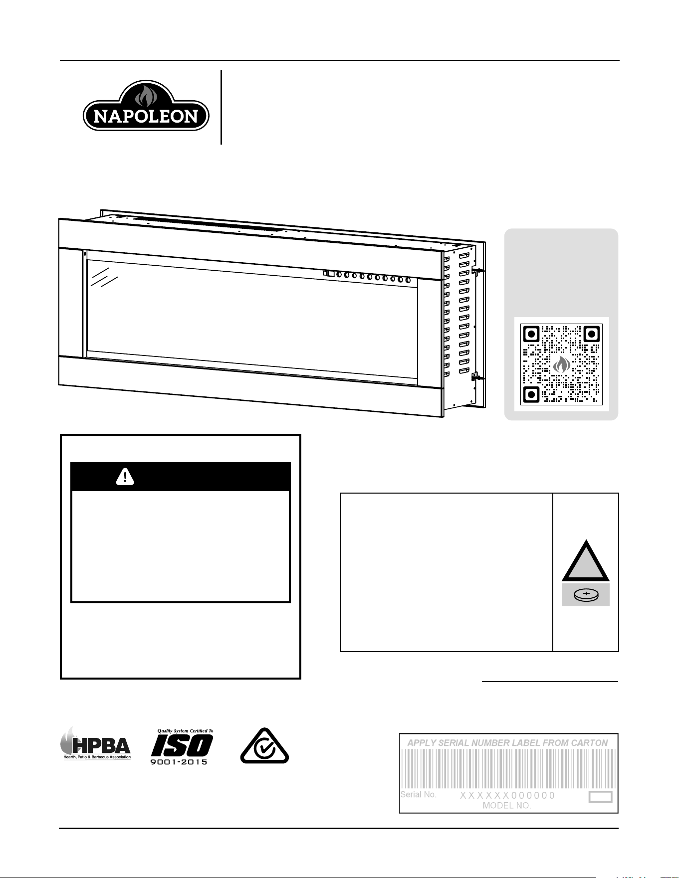
CLEARion™ ELITE
(NEFBD50HE-AU Illustrated)
To register
your
appliance,
scan here.
NEFBD50HE-AU / NEFBD60HE-AU
CERTIFIED TO
AS/NZS 60335.2.30:2023;
AS/NZS 60335.1:2020+ A1:2021
FOR INDOOR USE ONLY
INSTALLATION AND
OPERATION MANUAL
Wolf Steel Ltd., 24 Napoleon Rd., Barrie, ON, L4M 0G8 Canada
103 Miller Drive, Crittenden, Kentucky, 41030 USA
www.napoleon.com · [email protected]
W415-10008160 | A-0
INSTALLER: Leave this manual with the appliance.
CONSUMER: Keep this manual for future reference.
FIRE OR EXPLOSION HAZARD
If the information in these
instructions are not followed
exactly, a fire or explosion may
result causing property damage,
personal injury, or loss of life.
* Do not store or use gasoline
or other flammable vapors and
liquids in the vicinity of this or
any other appliance.
SAFETY INFORMATION
WARNING
SERIENNUMMER VOM KARTON AUFBRINGEN
Seriennr.
MODELL-NR.
BRENG HET SERIENUMMER VAN DE DOOS AAN
Serienr.
MODELNR.
NANESTE SÉRIOVÉ ČÍSLO Z KARTONU
Sériové číslo:
ČÍSLO MODELU:
!
WARNING:
Button Cell Batteries are Hazardous
(new or used).
KEEP AWAY FROM CHILDREN.
It can cause severe or fatal injuries in
2 hours or less if they are swallowed
or placed inside any part of the
body. If you suspect your child has
swallowed, please call 24-hour
poisons information centre on
13 11 26 for fast, expert advice.
EN
safety information
2 | W415-10008160 | A-0
WARNING
• If equipped with a heater, this appliance
can be hot when operated and can
cause severe burns if contacted.
• Do not operate appliance before reading and
understanding operating instructions. Failure
to operate appliance according to operating
instructions could cause fire or injury.
• Do not install damaged, incomplete or
substitute components.
• Do not burn wood or other materials in
this appliance.
• All electric appliances have hot and arcing or
sparking parts inside. Do not use it in areas
where a gas line, paint or flammable liquids
are present.
• Any safety screen or guard removed for
servicing must be replaced prior to operating
the appliance.
• It is imperative that the control compartments,
circulating blower and its passageway in the
appliance are kept clean. The appliance should
be inspected before use and at least annually
by a qualified service person. More frequent
cleaning may be required due to excessive
lint from carpeting, bedding material, etc. The
appliance area must be kept clear and free
from combustible materials, gasoline and other
flammable vapors and liquids.
• Under no circumstances should this
appliance be modified.
• Do not use this appliance if any part has been
under water. Immediately call a qualified
service technician to inspect the appliance
and to replace any part of the control system
which has been under water.
• If equipped with a glass door, do not operate
the appliance with the glass door removed,
cracked or broken. Replacement of the glass
should be done by a licensed or qualified
service person. Do not strike or slam shut the
appliance glass door.
• Keep the packaging material out of reach
of children and dispose of the material in a
safe manner. As with all plastic bags, these
are not toys and should be kept away from
children and infants.
• Servicing should be done only while the
appliance is disconnected from the power
supply circuit.
• Always unplug appliance when not in use.
• Do not operate this appliance with a
damaged cord or plug after the appliance
malfunctions, has been dropped
or damaged in any manner. Return
appliance to authorized service facility
for examination, electrical or mechanical
adjustment, or repair.
• Do not use outdoors.
• When installing this appliance in a room
where water is present, the installation must
comply with codes recognizing the increased
hazard of electrical shock and electrocution.
• Do not run cord under carpeting. Do not
cover cord with throw rugs, runners, or the
like. Arrange cord away from traffic area and
where it will not be tripped over.
• Connect to properly grounded outlets only.
• Do not insert or allow foreign objects to
enter any ventilation or exhaust opening as
this may cause an electric shock or fire, or
damage the appliance.
• It is normal for your electric appliance to
produce noise, especially when installed
in a quiet space such as a bedroom.
Note:
This appliance in NOT suitable for installation
in a bathroom.
EN
safety information
A-0 | W415-10008160 | 3
WARNING
• To prevent a possible fire, do not block air
intakes or exhaust in any manner. Do not
use on soft surfaces, like a carpet, where
openings may become blocked.
• Always plug appliances directly into a wall
outlet/receptacle. Never use an extension
cord or relocate cable power tap (outlet/
power strip).
• These appliances are tested and listed
for use only with the optional accessories
listed in these instructions. Use of optional
accessories not specifically tested for this
appliance could void the warranty and/or
result in a safety hazard.
For appliances equipped with a heater:
• Risk of burns. Power to the appliance should
be turned off and the appliance allowed to
cool before servicing. To disconnect power to
the appliance, turn controls to off, then remove
plug from outlet.
• Young children should be carefully
supervised when they are in the same
room as the appliance. Toddlers, young
children and others may be susceptible
to accidental contact burns. A physical
barrier is recommended if there are at risk
individuals in the house. To restrict access to
an appliance or stove, install an adjustable
safety gate to keep toddlers, young children
and other at risk individuals out of the room
and away from hot surfaces.
• Clothing or other flammable material should
not be placed on or near the appliance.
• Due to high temperatures, the appliance
should be located out of traffic and away from
furniture and draperies.
• Ensure you have incorporated adequate
safety measures to protect infants/toddlers
from touching hot surfaces.
• Even after the appliance is off, the glass and/
or screen will remain hot for an extended
period of time.
• Check with your local hearth specialty dealer
for safety screens and hearth guards to protect
children from hot surfaces. These screens and
guards must be fastened to the floor.
• Ensure clearances to combustibles are
maintained when building a mantel or shelves
above the appliance. Elevated temperatures
on the wall or in the air above the appliance
can cause melting, discolouration or damage
to decorations, a TV or other electronic
components.
• The appliance is not to be used by persons
(including children) with reduced physical,
sensory or mental capabilities, or lack of
experience and knowledge, unless they have
been given supervision or instruction.
• Children must be supervised not to play with
the appliance.
• Heater must not be located immediately
below a socket-outlet.
• If the supply cord is damaged, it must be
replaced by the manufacturer, its service
agent or similarly qualified persons in order to
avoid a hazard.
CAUTION
In order to avoid
overheating, do not cover the heater.
CAUTION
In order to avoid a
hazard due to inadvertent resetting of the
thermal cut-out, this appliance must not be
supplied through an external switching
device, such as a timer, or connected to a
circuit that is regularly switched on and off by
the utility.

EN
table of contents
4 | W415-10008160 | A-0
1.0 general information 5
1.1 dimensions 5
1.2 product information 5
1.3 general instructions 6
1.4 unpacking appliance 6
1.5 parts list 7
1.6 rating plate information 7
1.7 magnetic buttons 7
2.0 installation 8
2.1 locating the appliance 8
2.2 grounding the appliance 9
2.3 minimum clearance to combustibles 9
2.4 minimum mantel clearances 9
2.5 framing 10
2.6 installing the appliance 11
3.0 electrical information 13
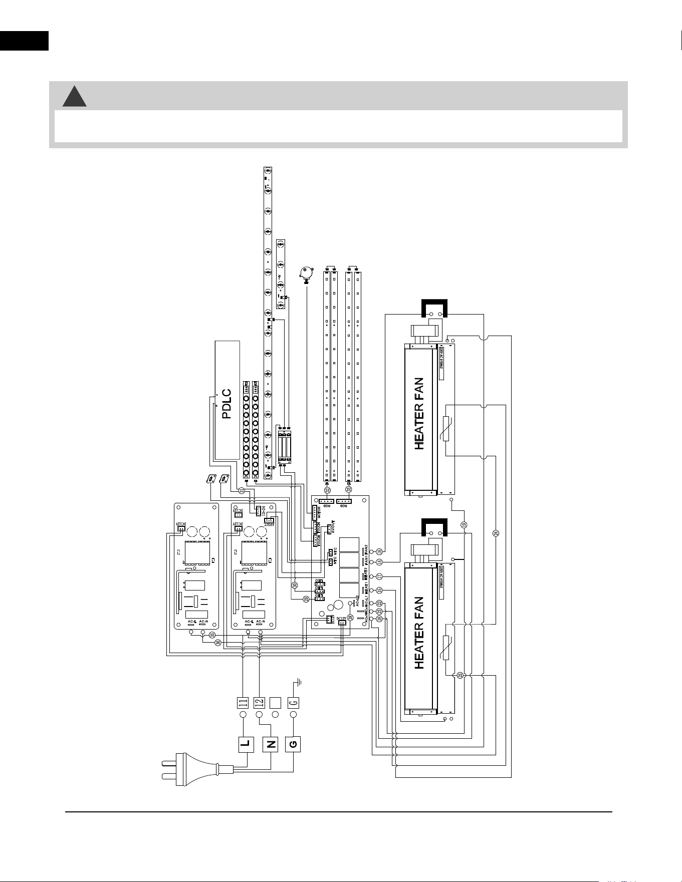
3.1 NEFBD50HE-AU wiring diagram 13
3.2 NEFBD60HE-AU wiring diagram 14
3.3 hard-wiring installation 15
4.0 finishing 16
4.1 front trim removal / installation 16
4.2 front glass removal / installation 16
4.3 media installation 17
4.3.1 log set and topaz glass installation 17
4.3.2 acrylic crystal media installation 17
5.0 operating instructions 18
5.1 main power button 18
5.2 operating touch panel and remote control 18
6.0 maintenance 21
6.1 cleaning 21
7.0 replacement parts 23
7.1 NEFBD50HE-AU overview 24
7.2 NEFBD60HE-AU overview 25
8.0 accessories 26
8.1 NEFBD50HE-AU accessories 26
8.2 NEFBD60HE-AU accessories 27
9.0 troubleshooting 28
10.0 warranty 30
The information throughout this manual is believed to be correct at the time of printing. Wolf Steel Ltd. reserves
the right to change or modify any information within this manual at any time without notice. Changes, other than
editorial, are denoted by a vertical line in the margin.
note:
EN
model designation
A-0 | W415-10008160 | 5
A
B
C
D
E
F
G
H
1.0 general information
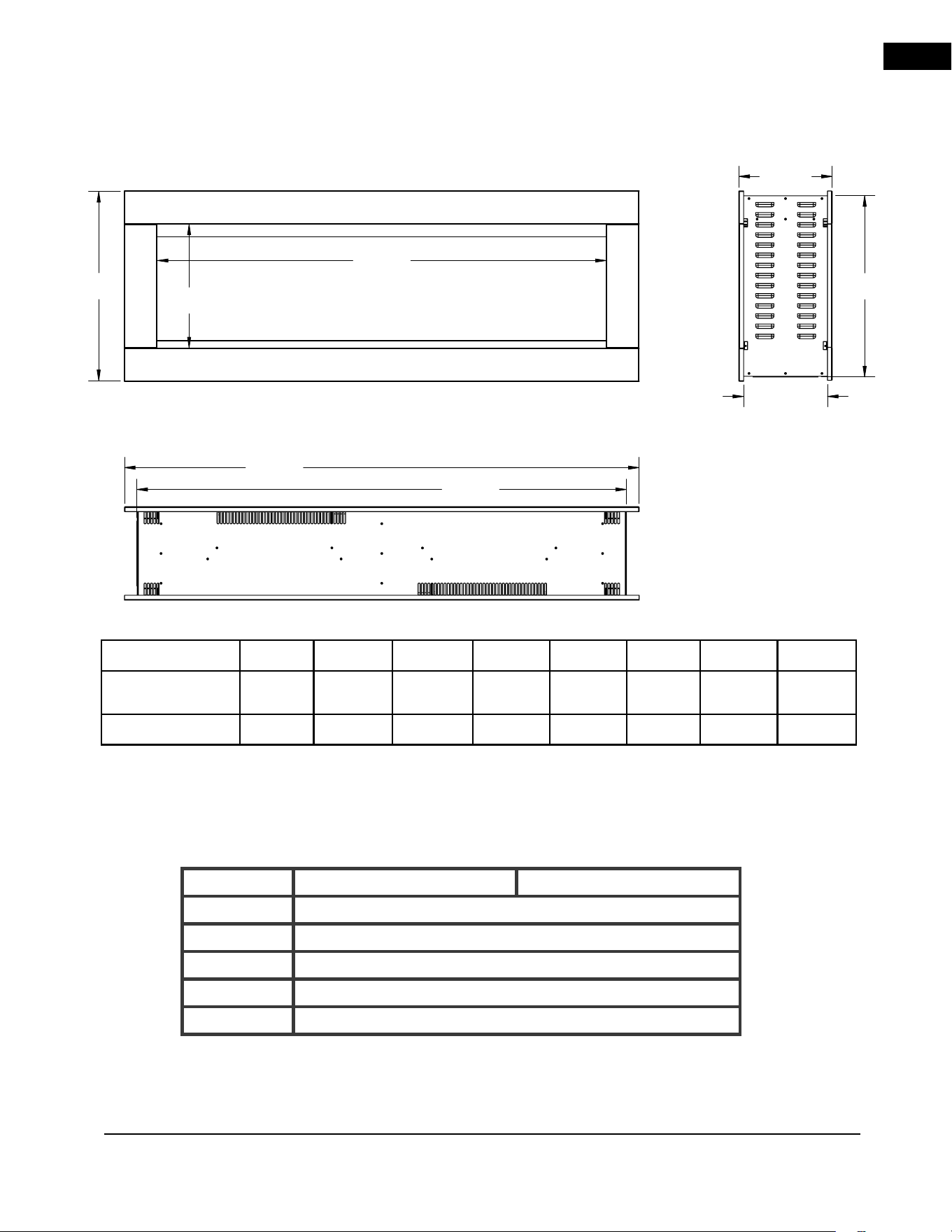
1.1 dimensions
right side view
top view
front view
A B C D E F G H
NEFBD50HE-AU
467mm 1208mm 1270mm 447mm 231mm 207mm 1108mm 306mm
NEFBD60HE-AU
518mm 1461mm 1524mm 498mm 234mm 208mm 1359mm 356mm
1.2 product information
This appliance has been tested in accordance with the SAA Standards for fixed and location-dedicated electric
room appliances in Australia and New Zealand. If you need assistance during installation, please contact your
local dealer.
NEFBD50HE-AU NEFBD60HE-AU
Description
See-Thru Electric Appliance
Type
Electric Appliance
Voltage
240V AC
Watts
MAX 1900W
Amps
Dedicated 10 AMP Grounded Circuit
EN
general information
6 | W415-10008160 | A-0
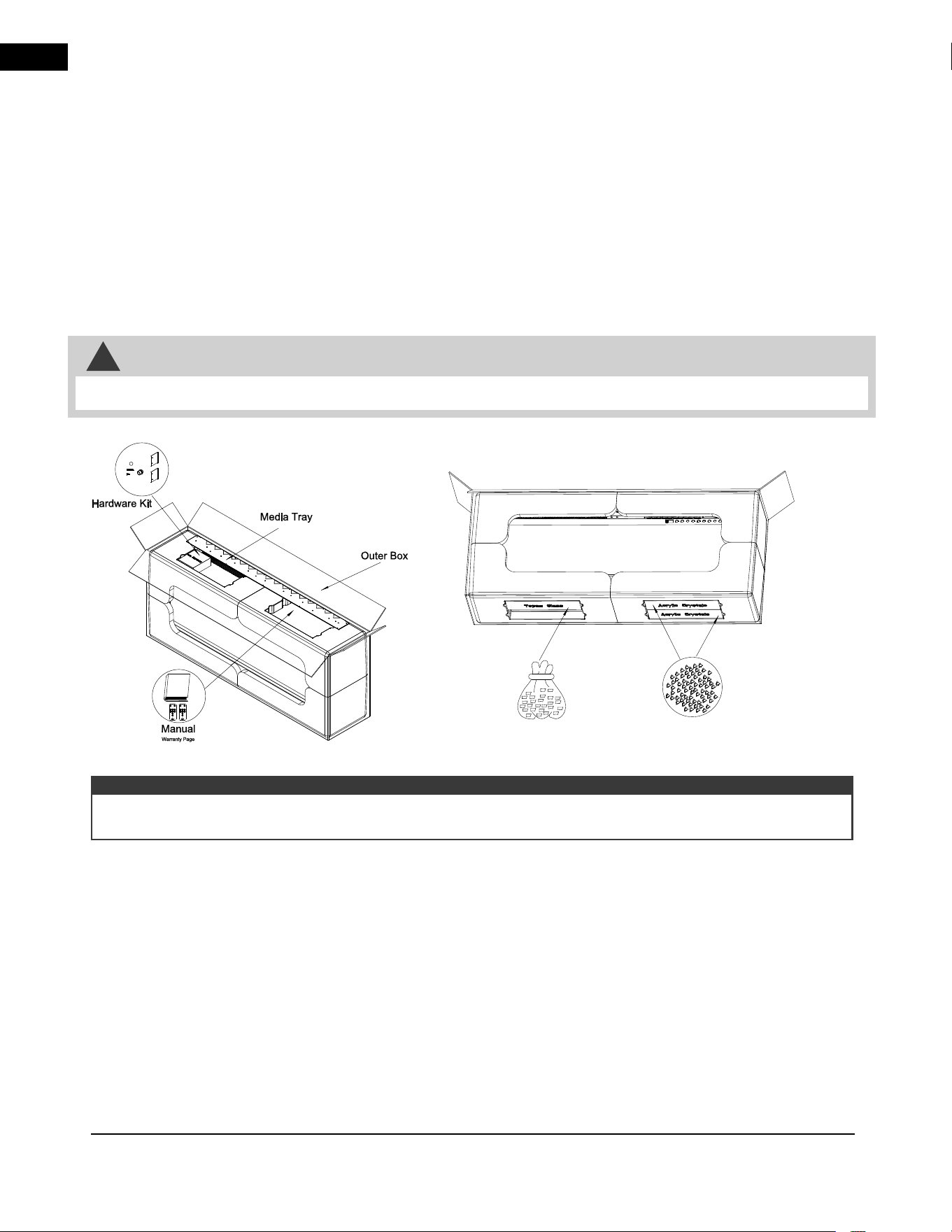
1.3 general instructions
NA
P
O
LEO
N
N
A
PO
L
E
O
N
Topaz Glass
Acrylic
Crystals
top view bottom view
The appliance comes with medium density fibreboard (MDF board) installed on the sides. See “installing the
appliance” section for more details about removal.
note:
1.4 unpacking appliance
!
WARNING
• Ensure to carefully remove the appliance from the box.
• The appliance may emit a slight, harmless odour when first used. This odour is normal and it is caused by the
initial heating of internal appliance elements and will not occur again.
• If your appliance does not emit heat when called for, consult the “operation” section of this manual for further information.
• Use with a SAA or UL certified surge protector.
This electric appliance meets the construction and safety standards of H.U.D. for application in manufactured
homes when installed according to these instructions.
As with most electronic devices, your new electric appliance has been designed to operate at
temperatures between 5°C (41°F) and 35°C (95°F). During the colder winter months, allow the appliance
to reach room temperature before turning it on.
EN
general information
A-0 | W415-10008160 | 7
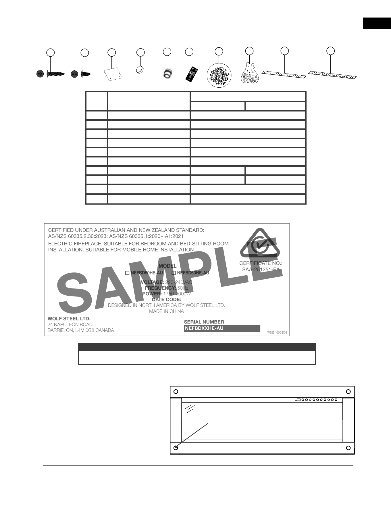
1.5 parts list
E
C
D
A
B
F
G
H
I J
Ref. Description
Quantity
NEFBD50HE-AU NEFBD60HE-AU
A Metal Screws (Black) 4
B Metal Screws (Black) 12
C Mounting Bracket 2
D Magnetic Buttons 8
E Strain Relief 1
F Remote Control 2
G Acrylic Crystals 1.6kg 2kg
H Topaz Glass 1.4kg 1.8kg
I Media Tray (Front) 1
J Media Tray (Back) 1
WOLF STEEL LTD.
SPECIFICATIONS: BLACK LETTERING ON SILVER BACK-
GROUND. MINIMUM FONT SIZE TO BE MINIMUM OF 8.5 PT
(3.2mm)
SERIAL NUMBERS TO BE ASCENDING FROM NEFBDXX-
HE-AU 000000 (INSERT APPLIANCE SIZE FOR "XX")
TITLE: RATING PLATE, NEFBD50-60 HE-AU
MATERIAL: CLASS IIIA-2 PERMANENT LEXAN ADHESIVE LABEL,
MINIMUM THICKNESS 0.1MM, NON WATER SOLUBLE ADHESIVE CAPA-
BLE OF WITHSTANDING A MAXIMUM TEMPERATURE OF 175°F (79°C).
REVISION NOTES: --0 07.28.2025 Initial. - JS
LABEL SIZE: 6”w x 2.75”h
DRAWING: W385-10008176
MODEL(S): NEFBD50-60 HE-AU
CREATION DATE: 07.28.2025
APPROVED BY: J. WHITEHEAD
CERTIFIED UNDER AUSTRALIAN AND NEW ZEALAND STANDARD:
AS/NZS 60335.2.30:2023; AS/NZS 60335.1:2020+ A1:2021
ELECTRIC FIREPLACE. SUITABLE FOR BEDROOM AND BED-SITTING ROOM
INSTALLATION. SUITABLE FOR MOBILE HOME INSTALLATION.
VOLTAGE: 220-240VAC
FREQUENCY: 50Hz
POWER: 1750-2000W
DATE CODE:
DESIGNED IN NORTH AMERICA BY WOLF STEEL LTD.
MADE IN CHINA
WOLF STEEL LTD.
24 NAPOLEON ROAD,
BARRIE, ON, L4M 0G8 CANADA
SERIAL NUMBER
NEFBDXXHE-AU
MODEL
NEFBD50HE-AU NEFBD60HE-AU
W385-10008176
CERTIFICATE NO.:
SAA-251251-EA
1.6 rating plate information
This illustration
is for reference
only. Refer to
the rating plate
on the appliance
for accurate
information.
SAMPLE
The rating plate must remain with the appliance at all times. It must not be removed.
note:
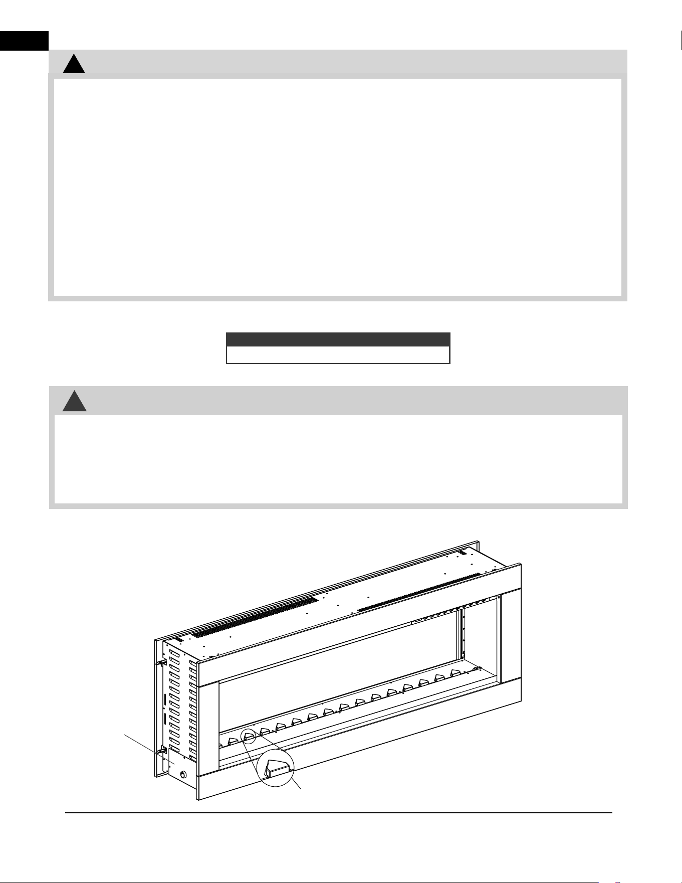
1.7 magnetic buttons
Your appliance is equipped with magnetic
buttons (see “parts list” and “replacement
parts” sections for details). The buttons are
optional and for decorative purposes
only.
If using, place the magnetic buttons on the
four corners of the appliance surround (Fig.
1-1). Avoid sliding as this can scratch the
painted surface.
Magnetic Button
Fig. 1-1
EN
installation
8 | W415-10008160 | A-0
2.0 installation
This is a see-thru electric appliance installed into a wall. Select a suitable location that is not susceptible to
moisture and is away from drapes, furniture and high traffic areas.
To determine the front of the appliance, ensure the junction box is located on the left side of the appliance and the
triangular covers are located on the other side of the firebox (see below).
42.5
!
WARNING
• Risk of fi re! The power cord must not be pinched against a sharp edge. Secure cord to avoid tripping or
snagging to reduce the risk of fi re, electric shock, or personal injury. Do not run cord under carpeting. Do not
cover cord with throw rugs, runners, or similar items. Arrange cord away from traffi c areas and where it will not
be tripped over.
• Risk of fi re! To prevent a possible fi re, do not block air intake or exhaust in any manner. Do not use on soft
surfaces where openings may become blocked.
• Risk of fi re! Do not blow or place insulation against the appliance.
• This electric appliance is tested and listed for use only with the approved optional accessories. Use of optional
accessories not specifi cally tested for this electric appliance could void the warranty and/or result in a safety
hazard.
• If the information in these instructions is not followed exactly, a fi re or explosion may result causing property
damage, personal injury, or death. Do not store or use gasoline or other fl ammable vapors in the vicinity of this
or any other appliance.
• This appliance is heavy. It is highly recommended that two people install this appliance.
• If your appliance is equipped with a heater, ensure the heater vents cannot, in any way, be covered as it may
create a fi re hazard.
• Do not run the power cord horizontally, directly below the appliance.
Follow all national and local electrical codes.
note:
2.1 locating the appliance
!
WARNING
Triangular
Cover
Junction
Box
Some parts hidden for clarity.
• Due to high temperatures, this electric appliance should be located out of traffic. Keep combustible materials,
such as furniture, pillows, bedding, papers, clothes, curtains, and similar items at least 36” (91.4cm) from the
front of the appliance.
• Never locate this electric appliance where it may fall into a bathtub or other water container.
• Wear safety gloves and safety glasses for protection during installation and maintenance.
• To prevent contact with sagging or loose insulation, the electric appliance must not be installed against vapor
barrier or exposed insulation. Localized overheating could occur and fire could result.
• Do not expose the electric appliance to the elements (such as rain, etc.).
For illustrative purposes only.
Appliance may not appear
exactly as illustated.
Front
View
EN
installation
A-0 | W415-10008160 | 9
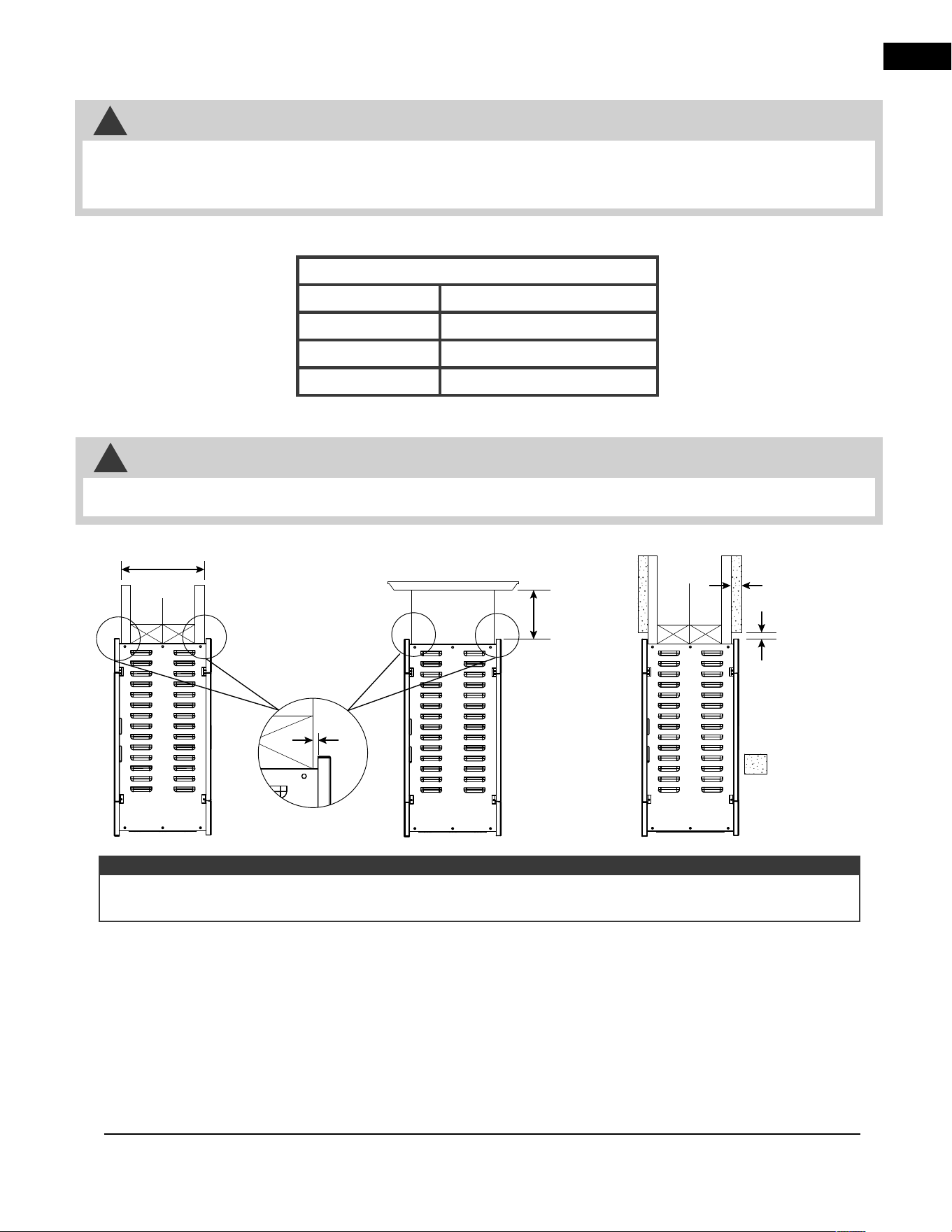
Measurements are taken from the front trim
Bottom
0”
Sides
0”
Front / Back
36” (914mm)
Mantel
8” (203mm)
• When using paint or lacquer to finish the mantel, the paint or lacquer must be heat resistant to prevent
discoloration.
!
WARNING
2.2 grounding the appliance
2.3 minimum clearance to combustibles
2.4 minimum mantel clearances
MANTEL
8”
(203mm)
WALL
8” (203mm)
WALL
2mm GAP
8” (203mm)
Trim
Clearance
3/8” (10mm)
minimum *
Finishing
materials
WALL
Finishing Material
Thickness
1 1/2” (38mm)
maximum.
• This appliance is for use with 240V AC.
• A bonded/grounded power source is mandatory for this appliance.
• This appliance must be connected to a dedicated 15 amp circuit. The use of an extension cord is NOT
permitted.
!
WARNING
* If finishing materials are installed on top of the already 203mm wall, a 10mm clearance must be maintained at
the top of the trim in order to service the appliance.
note:
EN
installation
10 | W415-10008160 | A-0
finished wall
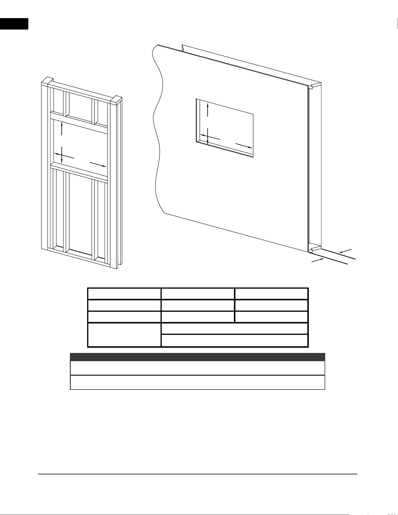
2.5 framing
A
B
A
B
C
*
* This measurement includes thickness of finishing materials.
important:
** Deep trim accessory available for this thickness of wall (see “accessories” section).
NEFBD50HE-AU NEFBD60HE-AU
A
456mm 506mm
B
1245mm 1497mm
C
203mm max.
114mm
** min
EN
installation
A-0 | W415-10008160 | 11
2.6 installing the appliance
A. Frame an opening (see “framing” section for details).
B.
Make hardwire connections on the left of the intended front side.
C. Remove the front trims of the appliance (see “front trim removal / installation” section).
D.
Remove the front glass from the appliance (see “front glass removal / installation” section).
E.
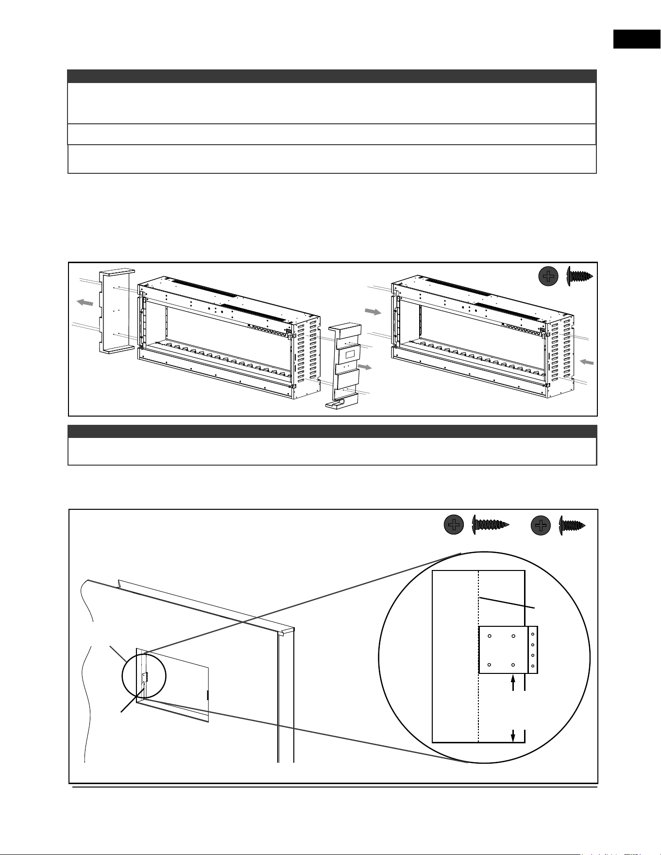
Remove the 2 MDF support ends from the appliance by removing the screws. Discard both MDF boards.
Use 4 new screws (supplied) on each side to cover MDF board screw holes (Fig. 2-1).
164mm
(NEFBD50HE-AU)
184mm
(NEFBD60HE-AU)
Center
of stud
EN
Fig. 2-2
It is recommended to have the walls of the appliance enclosure be finished (i.e. drywall) to avoid exposed
insulation or vapour barrier coming in contact with the appliance. This will ensure clearance to combustibles is
maintained.
note:
Wall anchors are not required when screwing into the wall stud.
B x 4
A x 4
It is recommended to use a magnetic screwdriver bit during installation to prevent the screws from falling into the
appliance.
Caution: The
MDF board is
used for
packaging only.
B x 8
Fig. 2-1
F. Mark the centre of the wall depth on the vertical stud and install the mounting brackets by aligning the
edge of the bracket with the centre marking. Measure 164mm (NEFBD50HE-AU) / 184mm (NEFBD60HE-
AU) from the bottom of the bracket to the bottom of the opening (Fig. 2-2).
FRONT
Hard-wiring
location
Installation uses 2 mounting brackets in opposite corners. Looking at the stud from the centre of the opening,
the brackets will extend out to the right (Fig. 2-2).
note:
164mm
(NEFBD50HE-AU)
184mm
(NEFBD60HE-AU)
EN
installation
12 | W415-10008160 | A-0
EN
EN
Fig. 2-3
Fig. 2-4
B x 4
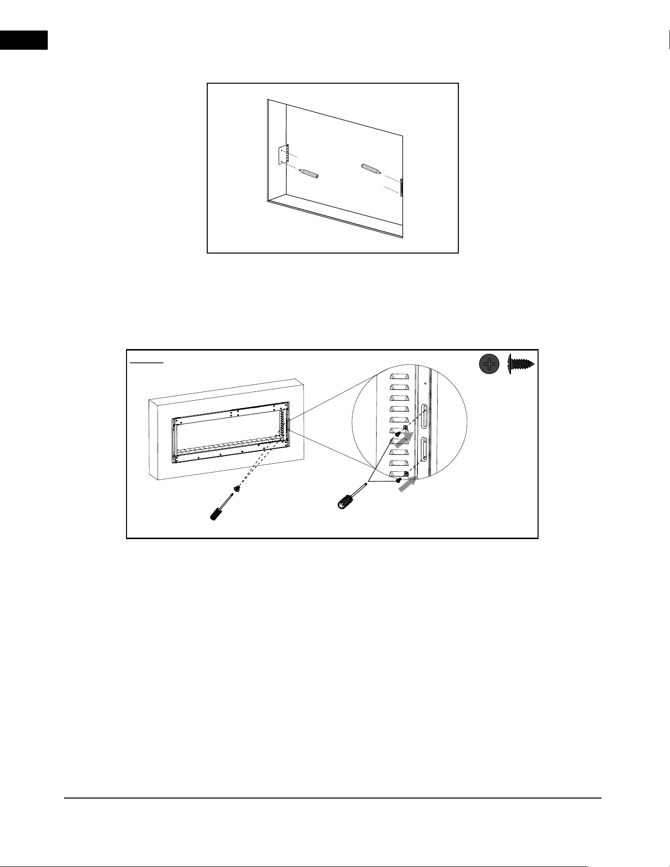
G. Mark the holes for the mounting bracket. Ensure the marked holes are on opposite sides, as the brackets
cannot be mounted on the same side (Fig. 2-3).
H.
Drill marked holes and secure the mounting brackets with screws (supplied).
I. Locate the appliance to the opening and position so that the hard wiring connections can be made (see
“hardwiring” section).
J.
Locate the appliance fully into the opening and position against the mounting brackets. Align the bracket
screw hole with the slots in the side of the appliance and screw through the slots to secure the appliance
into the mounting brackets. Repeat on opposite side (Fig. 2-4).
K. Install media (see “media installation” section).
L. Reinstall front glass and front trim (see “front glass removal / installation” and “front trim removal /
installation” sections).
NOTE: Screws go into
RIGHT side of appliance.
Repeat on
opposite side.
EN
electrical information
A-0 | W415-10008160 | 13
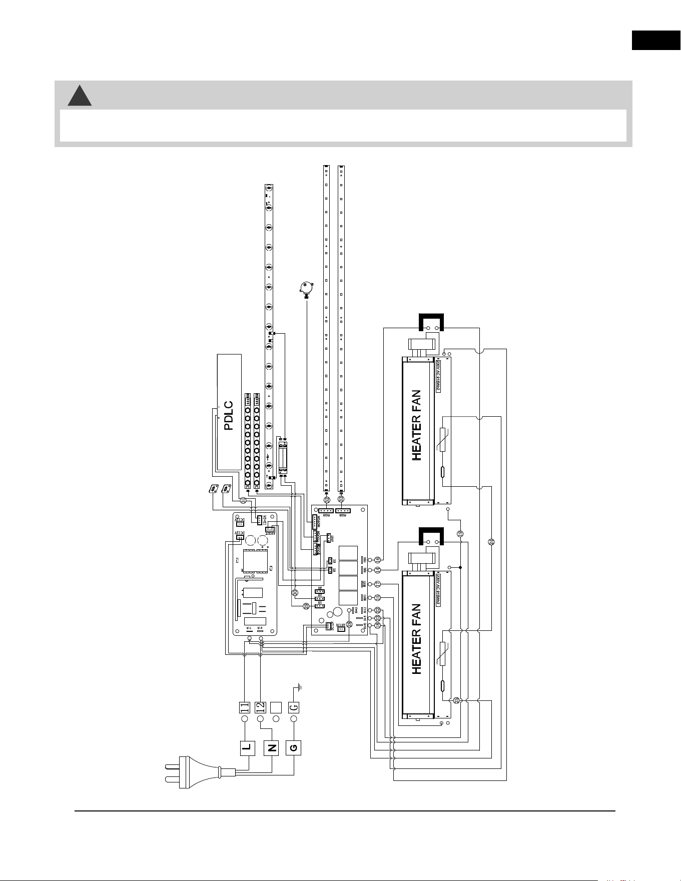
3.1 NEFBD50HE-AU wiring diagram
3.0 electrical information
• Turn off the appliance completely and let cool before servicing. Only a qualified service person should service
and repair this electric appliance.
!
WARNING
NEFBD50HE-AU
EN
electrical information
14 | W415-10008160 | A-0
3.2 NEFBD60HE-AU wiring diagram
• Turn off the appliance completely and let cool before servicing. Only a qualified service person should service
and repair this electric appliance.
!
WARNING
NEFBD60HE-AU
EN
electrical information
A-0 | W415-10008160 | 15
3.3 hard-wiring installation
Hard-Wiring Connection
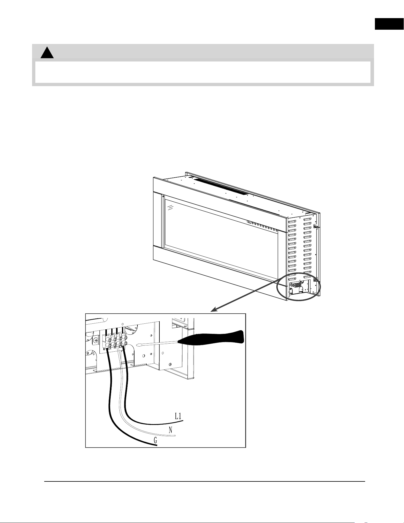
It is necessary to hard-wire this appliance. A qualified electrician must wire the appliance directly to the household
wiring. The wire and power supply breaker must rated for 220V minimum 10 amps. Use 14AWG for 240V. This
appliance requires a Neutral connection 240V connections.
This appliance must be electrically connected and grounded in accordance with local codes, if hard-wired. In the
absence of local codes, use the current AUSTRALIAN AND NEW ZEALAND STANDARD:
AS/NZS 60335.2.30:2023; AS/NZS 60335.1:2020+ A1:2021.
!
WARNING
• Turn off the appliance completely and let cool before servicing. Only a qualifi ed service person should service
and repair this electric appliance.
220V Hard-Wiring
EN
16 | W415-10008160 | A-0
4.0 finishing
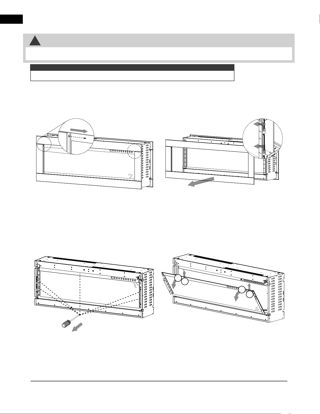
4.1 front trim removal / installation
4.2 front glass removal / installation
• Before the front trim or glass is removed or installed, unplug the appliance and wait until it is cool to the touch.
• Trim can be heavy and fragile. Handle with care.
!
WARNING
A. Remove the 5 screws holding the front glass in place (Fig. 4-3).
B. Have 2 people lift the front glass up and out, pivoting it away from the side panels (Fig. 4-4). Place the
front glass face down on a soft, non-abrasive surface.
C. Reverse these steps to install the front glass.
Fig. 4-3
Fig. 4-4
1
1
2
2
A. Remove the 2 screws holding the front trim in place (Fig. 4-1). Set screws aside.
B. Have 2 people lift the front trim off the hooks located inside the firebox (Fig. 4-2). Place front trim face
down on a soft, non-abrasive surface.
C. Reverse these steps to install the front trim.
Fig. 4-2
Fig. 4-1
Some parts
hidden for
clarity.
Removal / installation steps are the same for both sides of appliance (i.e. front and back).
note:
Repeat on
opposite side.
Repeat on
opposite side.
Repeat on
opposite side.
Repeat on
opposite side.
EN
finishing
A-0 | W415-10008160 | 17
4.3 media installation
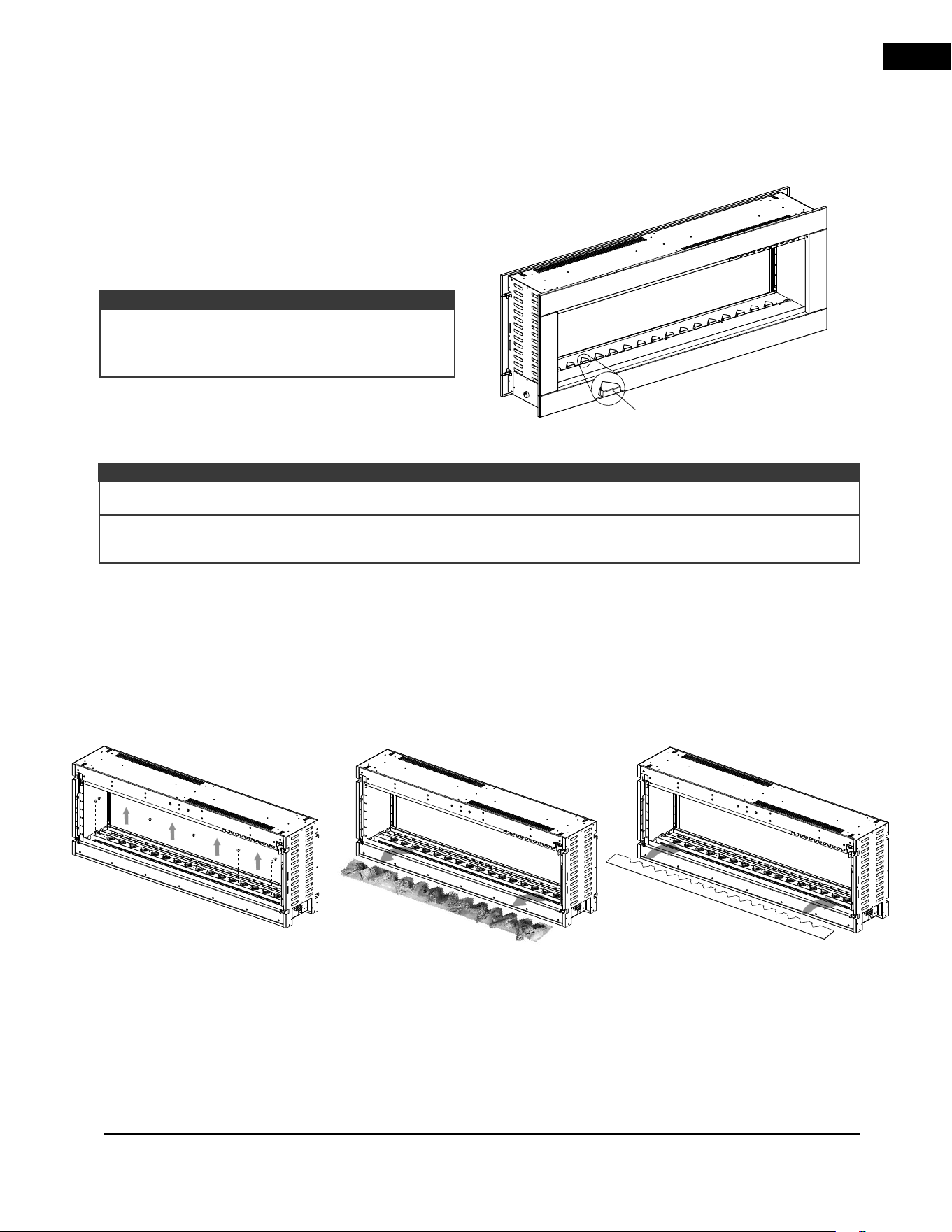
4.3.1 log set and topaz glass installation
A. Remove the topaz glass.
B. Remove the screws from the log set base/media tray. Keep the screw with the log set for future use (Fig.
4-6).
C. Remove the log set (Fig. 4-7).
D. Install the media tray, ensuring to NOT re-install the screws as they can cause the media tray to bow
when heated (Fig. 4-8).
E. Carefully place the acrylic crystals into the media tray, creating an even layer from side to side.
F. Reverse these steps to re-install the log set with topaz glass.
The log set comes pre-installed with the appliance and
has to be finished with topaz glass. Carefully place the
topaz glass between the log set (front and back sides)
after framing the appliance and before installing the
front glass.
There are 2 media options for this appliance: log set and acrylic crystals. The log set comes pre-installed with the
appliance and has to be finished with topaz glass (see “log set and topaz glass installation” section). If desired, the
log set and topaz glass can be switched out with acrylic crystals (see “acrylic crystal media installation” section).
note:
Do NOT cover triangular covers on the back side
of the appliance (Fig. 4-5). Blocking the triangular
covers with media will alter the flame appearance.
Fig. 4-6
4.3.2 acrylic crystal media installation
Fig. 4-8
Ensure to vacuum up any topaz glass or acrylic crystals outside the media tray area before operation.
Do NOT cover triangular covers on the back side of the appliance. Blocking the triangular covers with media will
alter the flame appearance.
note:
For clarity, logs are not illustrated.
Fig. 4-7
Triangular
Cover
Fig. 4-5
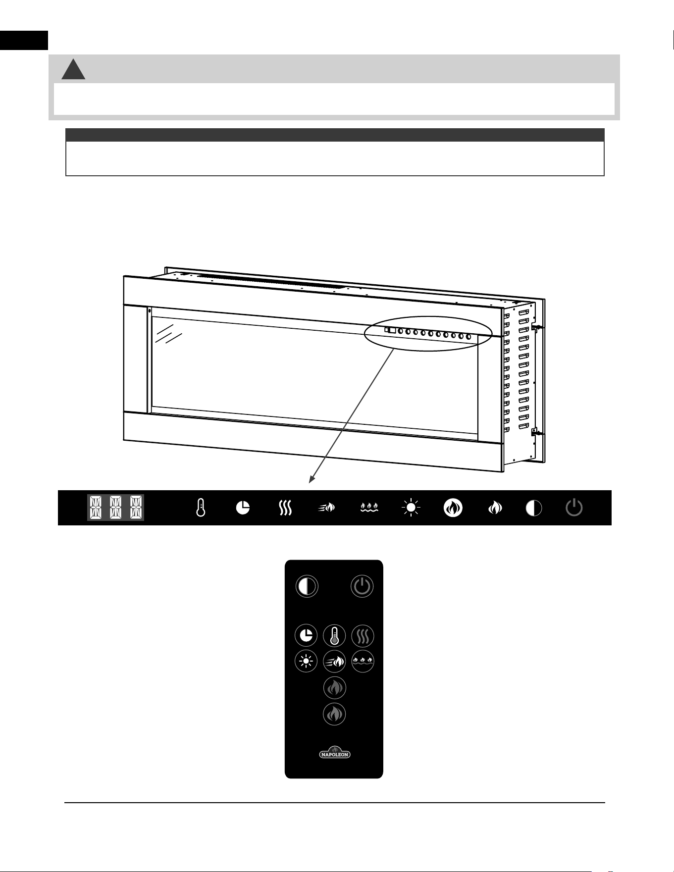
EN
operating instructions
18 | W415-10008160 | A-0
5.0 operating instructions
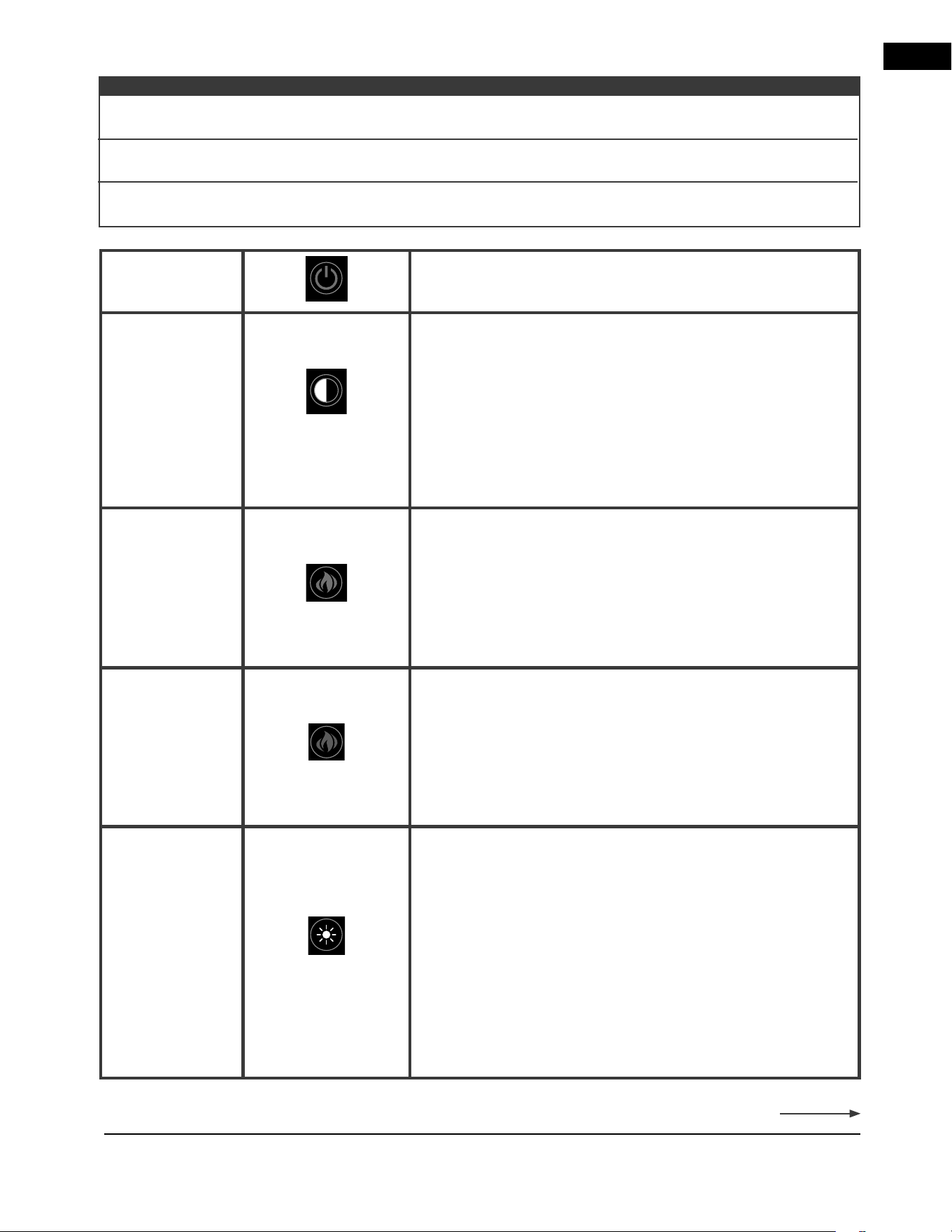
The main power button is located in the top right corner of the glass panel.
5.1 main power button
5.2 operating touch panel and remote control
Ensure the house circuit breakers for the power supply are turned on. In the event of a power failure, the
appliance will lose its memory function and will reset to factory mode when the power returns.
note:
• While the appliance is operating, do not remove the trim. This will cause the remote control and touch panel to
malfunction.
!
WARNING
remote control
touch panel
For illustrative purposes only. Touch panel may
not always appear as illustrated.
EN
operating instructions
A-0 | W415-10008160 | 19
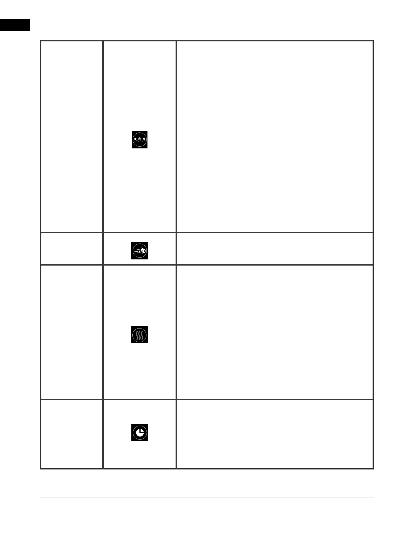
Power
Turns appliance on and off.
Privacy Glass
Control
Controls the privacy glass.
Settings:
G-1 - Half transparent mode (default)
G-2 - Full transparent mode
G-0 - No transparent mode
Press and hold the button for 5 seconds to lock/unlock the
privacy glass to G-0 status. When unlocked, the appliance will
return to G-1 (default).
Orange Flame
Controls orange flame brightness.
Settings:
OF4 - Brightest flame
OF3 - Bright flame
OF2 - Dim flame
OF1 - Dimmest flame
OF0 - Flame off
Blue Flame
Controls blue flame brightness.
Settings:
BF4 - Brightest flame
BF3 - Bright flame
BF2 - Dim flame
BF1 - Dimmest flame
BF0 - Flame off
Ember Bed
Brightness
Controls the brightness of the ember bed light.
NOTE: If the ember bed colour is set to L16, the ember bed
brightness setting cannot be changed.
Settings:
B-5 - Fade in and out
B-4 - Brightest
B-3 - Bright
B-2 - Dim
B-1 - Dimmest
B-0 - Off
Continued on next page
When only the heat is on (i.e. no flames, no ember bed lights, etc.), the display window will be dim and show H1
or the chosen temperature.
note:
After the heater is turned off, the blower will continue running for 10 seconds. This helps to remove heat from
the appliance and bring down its temperature.
When only the fan is on (i.e. no flames, no ember bed lights, etc.), the display window will be dim and show
FAN.
EN
operating instructions
20 | W415-10008160 | A-0
Ember Bed
Colour
Controls ember bed light settings.
NOTE: Ember bed brightness must be between B-4 and B-1 to
control ember bed colour.
Settings:
L01 - Orange
L02 - Red
L03 - Blue
L04 - Yellow
L05 - Green
L06 - Purple
L07 - Sky Blue
L08 - Purple Red
L09 - White
L10 - Pink
L11 - Yellow Green
L12 - Ice Blue
L13 - Orange Red
L14 - Light Green
L15 - Magenta
L16 - Autocycle
L17 - Lock a colour during L16 cycle
Flame Speed
Controls flame speed.
Settings: S-3, S-4, S-5, S-1, S-2
Heater
Turns the heater and blower on/off.
Settings:
H-0 - Heater and blower off
FAN - Blower on
H-1 - Heater on
(750W each side @ 240V / 1900W each side @ 240V)
LOC - Lock-out of heater and thermostat
NOTE: Child safety feature. Heater can be locked or unlocked by
holding the button for 5 seconds. Heater and blower functions
are disabled when it is locked. The “LO” will be displayed.
NOTE: Each side of the appliance has an independent heater
control.
Timer
Sets the timer.
Settings:
30M, 1Hr, 2Hr, 3Hr, 4Hr, 5Hr, 6Hr, 7Hr, 8Hr.
NOTE: The display will read “---” after completing the 9 timer
settings.
EN
operation instructions
A-0 | W415-10008160 | 21
6.0 maintenance
!
WARNING
• Always turn the heater off and unplug the power cord from the outlet before cleaning, performing maintenance,
or moving this appliance. Failure to do so could result in electric shock, fire, or personal injury.
• Never immerse in water or spray with water. Doing so could result in electric shock, fire, or personal injury.
Metal:
• Buff using a soft cloth, slightly dampened with a citrus oil-based product.
• Do not use brass polish or household cleaners as these products will damage the metal trim.
Glass:
• Use a good quality cleaner sprayed onto the cloth or towel. Dry thoroughly with a paper towel or lint-free
cloth.
• Never use abrasive cleaners, liquid sprays, or any cleaner that could scratch the surface.
Vents:
• Use a vacuum or duster to remove dust and dirt from the heater and vent areas.
Plastic:
• Wipe gently with a slightly damp cloth and a mild solution of dish soap and warm water.
• Never use abrasive cleaners, liquid sprays, or any cleaner that could scratch the surface.
6.1 cleaning
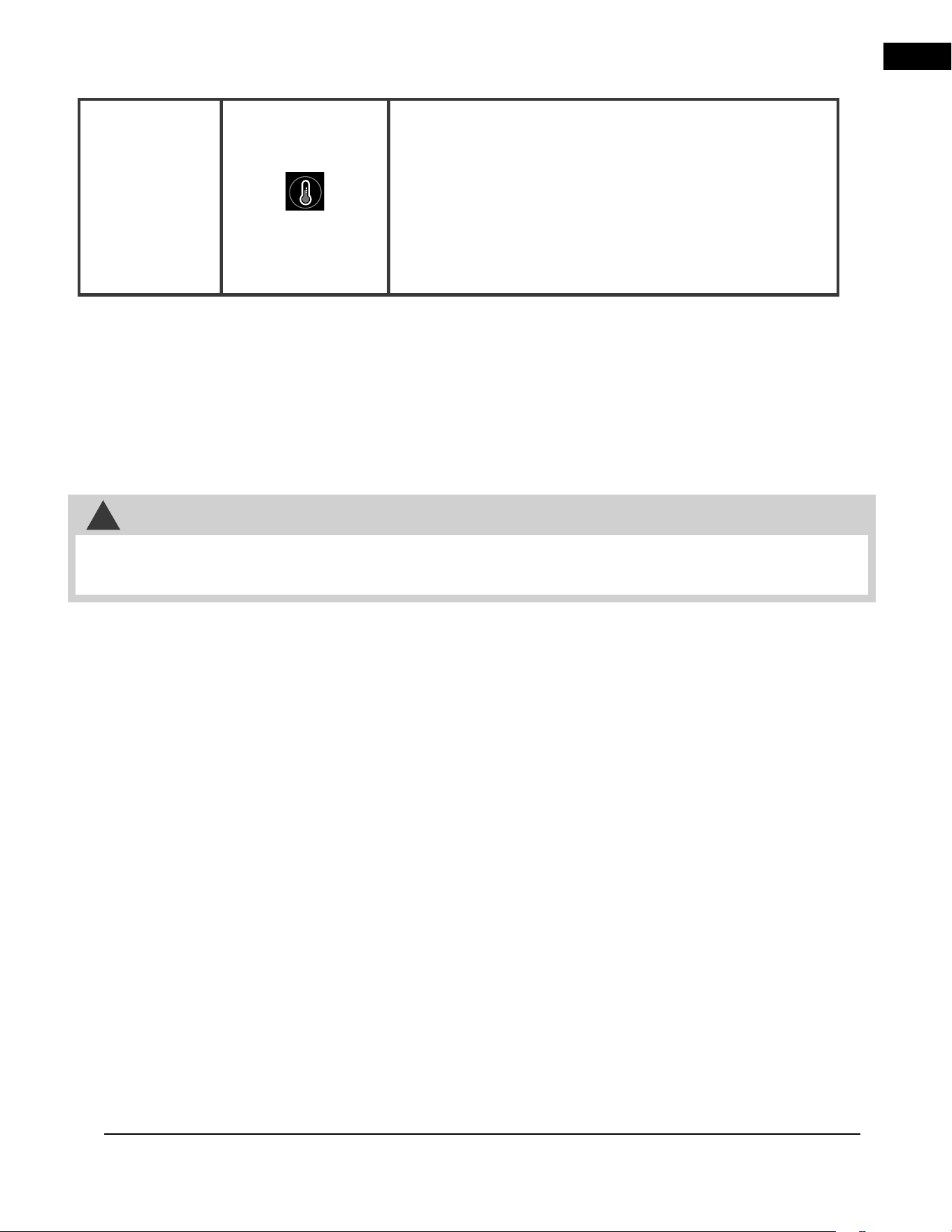
Temperature
Control
Sets desired temperature.
Settings:
18°C (64°F), 19°C (66°F), 20°C (68°F), 21°C (70°F), 22°C (72°F),
23°C (74°F), 24°C (76°F), 25°C (78°), 26°C (80°F), 27°C (82°F),
and OFF.
To switch between °C and °F or vice versa, hold the temperature
control button for 5 seconds.
EN
maintenance
22 | W415-10008160 | A-0
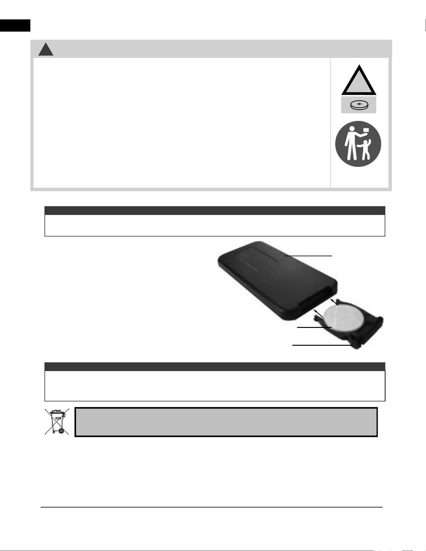
1. To replace the existing battery remove the battery
holder.
2. To remove the battery holder turn remote onto rear
side and press the left side lever towards the center
while pulling the battery holder out using the slot
provided.
3. Replace existing battery, type CR 2025, with a
new battery and reinstall the battery holder into the
remote by sliding it into position, as shown.
Remote
(Rear Side)
Battery Holder
Battery (CR 2025)
The remote control has a removable plastic tab to prolong the battery life while shipping. Remove the tab for the
remote control to function.
The remote control must remain within 5 meters or 17 feet of the appliance to be effective. This range may
be reduced when battery power is depleted. The remote control must be aimed at the bottom centre of the
appliance for it to function most effectively.
note:
note:
Batteries must be disposed of according to the local laws and regulations. Some batteries may be
recycled, and may be accepted for disposal at your local recycling center. Check with your
municipality for recycling instructions.
Les piles doivent être mises au rebut conformément aux lois et à la réglementation locales.
Certaines piles peuvent être recyclées et acceptées dans votre centre de recyclage local. Rensei-
gnez-vous auprès de votre municipalité au sujet des directives de recyclage.
Las baterías deben desecharse de acuerdo con las leyes y regulaciones locales. Algunas baterías
pueden reciclarse, y es posible que su centro de reciclado local las acepte para desecharlas.
Consulte en su municipalidad sobre las instrucciones para el reciclado.
!
WARNING
!
• Remove and immediately recycle or dispose of used batteries according to local regulations
and keep away from children. Do NOT dispose of batteries in household trash or incinerate.
• Even used batteries may cause severe injury or death.
• Call a local poison control center for treatment information.
• Non-rechargeable batteries are not to be recharged.
• Do not force discharge, recharge, disassemble, heat above (manufacturer’s specifi ed
temperature rating) or incinerate. Doing so may result in injury due to venting, leakage or
explosion resulting in chemical burns.
• Ensure the batteries are installed correctly according to polarity (+ and -).
• Do not mix old and new batteries, diff erent brands or types of batteries, such as alkaline,
carbon-zinc, or rechargeable batteries.
• Remove and immediately recycle or dispose of batteries from equipment not used for an
extended period of time according to local regulations.
• Always completely secure the battery compartment. If the battery compartment does not close
securely, stop using the product, remove the batteries, and keep them away from children.
EN
A-0 | W415-10008160 | 23
7.0 replacement parts
!
WARNING
26.1
• Failure to position the parts in accordance with this manual or failure to use only parts specifi cally approved
with this appliance may result in property damage or personal injury.
Contact your dealer for questions concerning prices and policies on replacement parts. Normally, all parts can
be ordered through your Authorized dealer / distributor.
For warranty replacement parts, a photocopy of the original invoice will be required to honour the
claim.
When ordering replacement parts always give the following information:
• Model & Serial Number of appliance
• Installation date of appliance
• Part number
• Description of part
• Finish
Parts, part numbers, and availability are subject to change without notice.
Parts identifi ed as stocked will be delivered within 2 to 5 business days for most delivery
destinations.
Parts not identifi ed as stocked will be delivered within a 2 to 4 week period, for most cases.
Parts identifi ed as ‘SO’ are special order and can take up to 90 days for delivery.
EN
replacement parts
24 | W415-10008160 | A-0
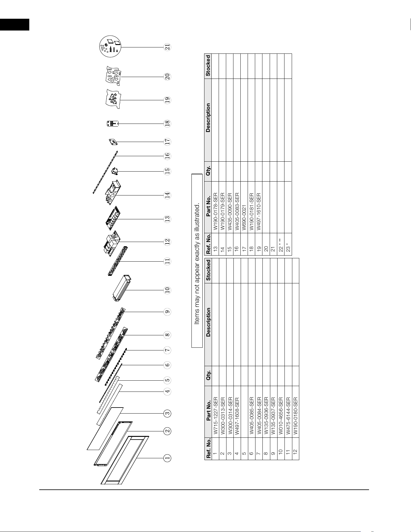
7.1 NEFBD50HE-AU overview
Items may not appear exactly as illustrated.
NEFBD50HE OVERVIEW
** These magnetic buttons are for decorative purposes only. They are meant to be placed in the corners of the appliance surround (see “magnetic buttons” section for details).
* Parts not illustrated.
Part No.
Ref. No.
Qty.
Description
Stocked
1
2
3
4
5
6
7
8
9
10
11
12
W715-1227-SER
W405-0085-SER
W300-0314-SER
W135-0937-SER
W405-0084-SER
W497-1609-SER
W135-0936-SER
W497-1608-SER
W010-4656-SER
W475-6144-SER
W300-0313-SER
W190-0180-SER
Front trim, black
Privacy glass
Front, media tray holder
LED ember bed light strip
Triangular cover
Back, media tray holder
Back, log set assembly
Front, log set assembly
Heater and blower assembly
Touch-on control panel with receiver
Front glass
120V/240V wiring PCB board
Yes
Yes
Yes
Yes
Yes
Yes
Yes
Yes
Yes
Yes
Yes
Yes
Part No.
Ref. No.
Qty.
Description
Stocked
15
13
16
17
20
18
19
14
21
22 * **
23 *
W190-0181-SER
W690-0021
W190-0178-SER
W300-0315-SER
W405-0083-SER
W497-1610-SER
W435-0090-SER
W190-0179-SER
W370-0191-SER
W430-0023-SER
W527-0042-SER
LED light for flame
Main PCB board
Step motor
Power driver for privacy glass
Thermostat
Remote control
Acrylic crystals
Topaz glass
Hardware kits & wall mount bracket
Magnetic buttons (x8)
Reflector drum
Yes
Yes
Yes
Yes
Yes
Yes
Yes
Yes
Yes
Yes
Yes
2
2
1
1
1
2
16
1
1
2
2
1
1
1
1
1
2
2
2
1
1
1
1
NAP OLEO N
EN
replacement parts
A-0 | W415-10008160 | 25
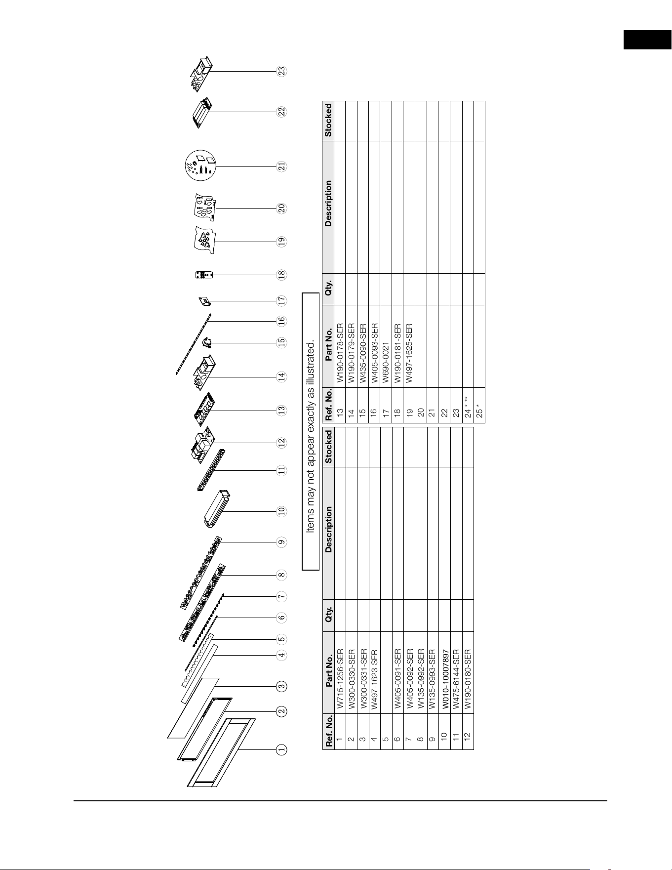
7.2 NEFBD60HE-AU overview
Items may not appear exactly as illustrated.
NEFBD60HE-AU OVERVIEW
** These magnetic buttons are for decorative purposes only. They are meant to be placed in
the corners of the appliance surround (see “magnetic buttons” section for details).
* Parts not illustrated.
Part No.
Ref. No.
Qty.
Description
Stocked
1
2
3
4
5
6
7
8
9
10
11
12
W715-1256-SER
W405-0091-SER
W300-0331-SER
W135-0993-SER
W405-0092-SER
W497-1624-SER
W135-0992-SER
W497-1623-SER
W010-10007897
W475-6144-SER
W300-0330-SER
W190-0180-SER
Front trim, black
Privacy glass
Front, media tray holder
LED ember bed light strip
Triangular cover
Back, media tray holder
Back, log set assembly
Front, log set assembly
Heater and blower assembly
Touch-on control panel with receiver
Front glass
120V/240V wiring PCB board
Yes
Yes
Yes
Yes
Yes
Yes
Yes
Yes
Yes
Yes
Yes
Yes
Part No.
Ref. No.
Qty.
Description
Stocked
15
13
16
17
20
18
19
14
21
22
23
W190-0181-SER
W690-0021
W190-0178-SER
W300-0332-SER
W405-0093-SER
W497-1625-SER
W435-0090-SER
W190-0179-SER
W370-0191-SER
W190-0199-SER
W190-0200-SER
LED light for flame
Main PCB board
Step motor
Power driver for privacy glass
Thermostat
Remote control
Acrylic crystals
Topaz glass
Hardware kits & wall mount bracket
Resistance board
Power board 2
Yes
Yes
Yes
Yes
Yes
Yes
Yes
Yes
Yes
Yes
Yes
2
2
1
1
1
2
20
1
1
2
2
1
1
1
1
1
2
2
2
1
1
1
1
NAPO LEON
24 * **
25 *
W430-0023-SER
W527-0043-SER
Magnetic butons (x8)
Reflector drum
Yes
Yes
1
1
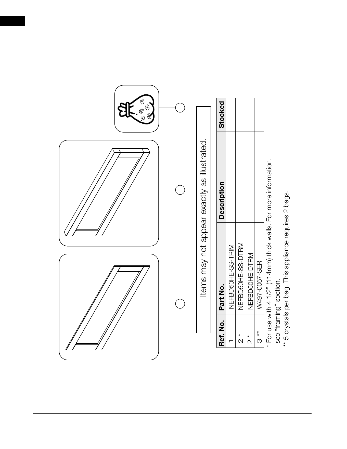
EN
26 | W415-10008160 | A-0
8.0 accessories
Ref. No.
Part No.
Description
1
2 *
2 *
Items may not appear exactly as illustrated.
NEFBD50HE-SS-TRIM
Stocked
Stainless steel trim (x2)
Ref. No.
NEFBD50HE-DTRM
Black deep trim (x2)
NEFBD50HE-SS-DTRM
Stainless steel deep trim (x2)
1
* For use with 4 1/2” (114mm) thick walls. For more information,
see “framing” section.
2
3 **
W497-0067-SER
Bag of crystals, large
** 5 crystals per bag. This appliance requires 2 bags.
3
Yes
Yes
Yes
Yes
8.1 NEFBD50HE-AU accessories
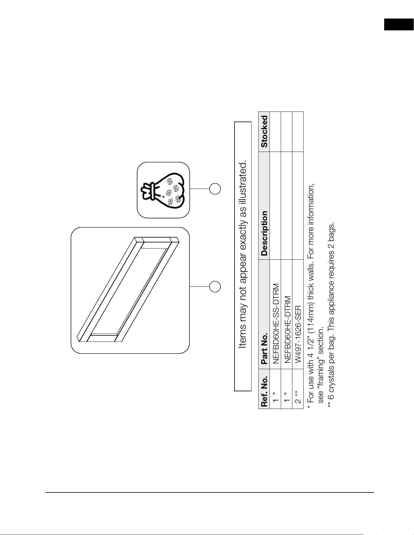
EN
accessoires
A-0 | W415-10008160 | 27
Ref. No.
Part No.
Description
1 *
1 *
2 **
Items may not appear exactly as illustrated.
Stocked
Ref. No.
NEFBD60HE-DTRM
Black deep trim (x2)
NEFBD60HE-SS-DTRM
Stainless steel deep trim (x2)
* For use with 4 1/2” (114mm) thick walls. For more information,
see “framing” section.
1
W497-1626-SER
Bag of crystals, large
** 6 crystals per bag. This appliance requires 2 bags.
2
Yes
Yes
Yes
8.2 NEFBD60HE-AU accessories
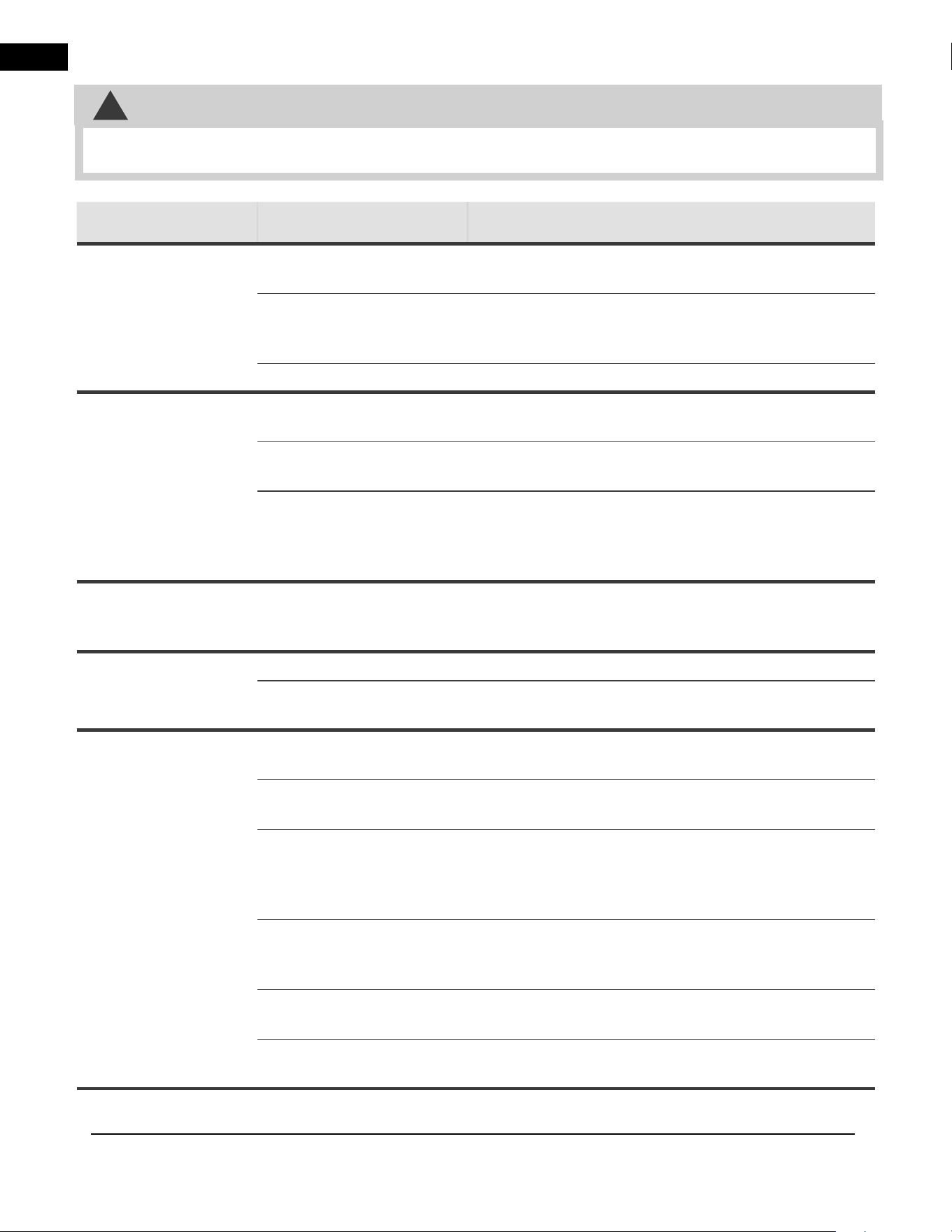
EN
28 | W415-10008160 | A-0
9.0 troubleshooting
!
WARNING
• Turn off the appliance completely and let cool before servicing. Only a qualified service person should service
and repair this electric appliance.
symptom problem solution
Appliance will not
come on when
power button/switch
is put into the “on”
position.
House circuit breaker has
tripped.
Reset house circuit breaker.
Appliance has overheated
and safety thermal switch
has tripped.
Unlug power or turn off the circuit breaker, allow
appliance to cool for 15 minutes, then plug in the
appliance or turn the breaker on.
Main PCB board issue. Inspect the circuit board and replace, if necessary.
Appliance turns off
and will not turn on.
House circuit breaker has
tripped.
Reset house circuit breaker.
Appliance’s fuse has
blown.
Replace the fuse.
Appliance has overheated
and safety thermal switch
has tripped.
Unplug power or turn off the circuit breaker, allow
appliance to cool for 15 minutes to reset the thermal
switch, then plug in the appliance or turn the breaker
on.
Appliance has
returned to default
settings.
Power failure. Re-program appliance to original settings (not
applicable with all appliances).
Remote control
does not work.
Low/dead batteries. Replace batteries in remote control.
Remote receiver
malfunction.
Ensure remote receiver is not blocked. Replace
control panel.
No warm air coming
out of the appliance.
Heater setting not
selected.
See “operation” section.
Heater has been locked
out.
See “operation” section.
Room temperature is
higher than appliance
setting (if set to room
temperature).
Reset temperature setting.
Appliance has overheated
and safety thermal switch
has tripped.
Unplug power or turn off the circuit breaker. Allow for
appliance to cool for 15 minutes.
Hard-wire connections are
not correct (if applicable).
See “hard-wiring installation” section.
Heater issue. Inspect the blower and heater and replace, if
necessary.
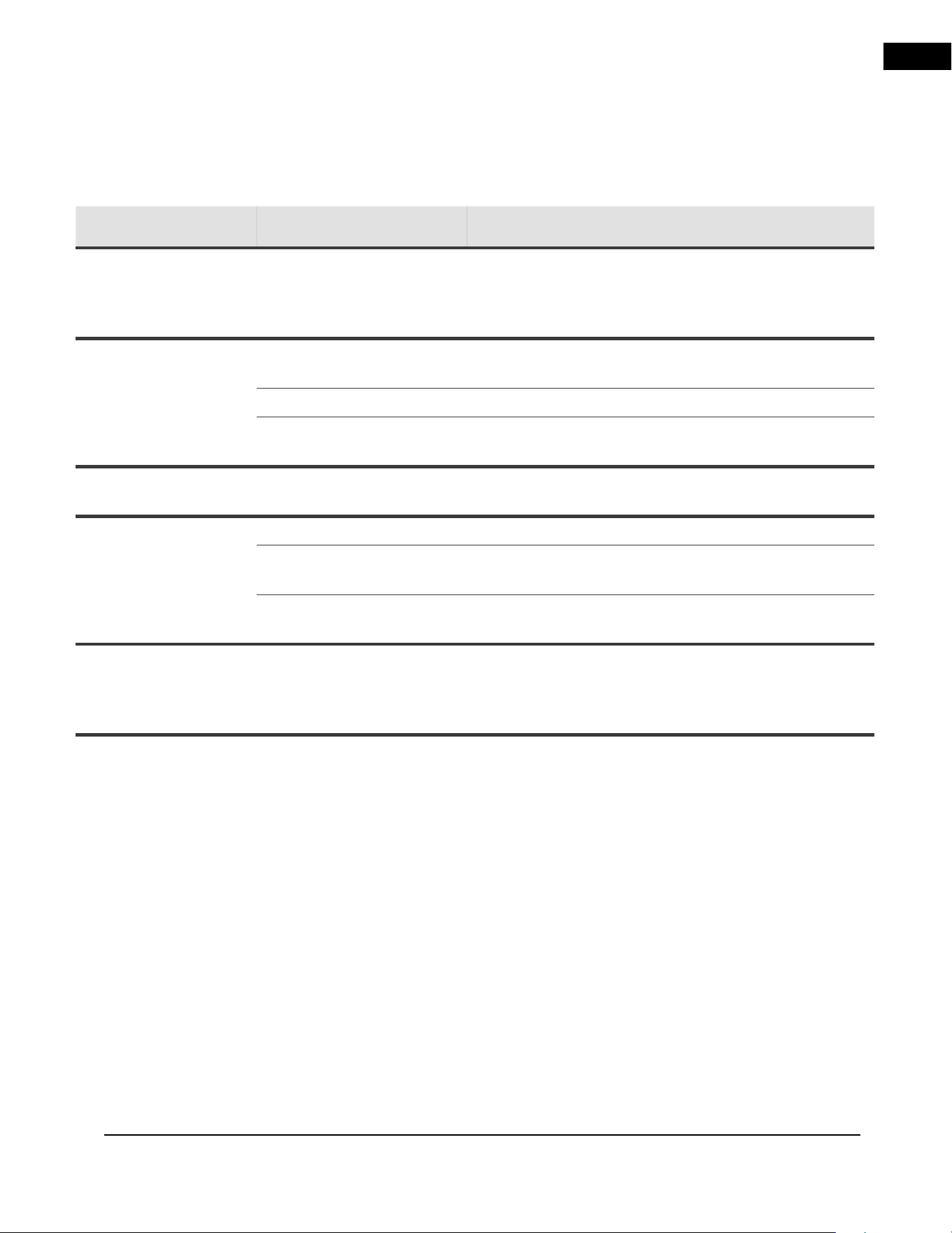
EN
troubleshooting
A-0 | W415-10008160 | 29
symptom problem solution
Heater shuts off
automatically.
Room is too warm. The heater has a built-in thermostat so it will shut
off automatically once the pre-set temperature is
reached. It will also turn on automatically if the room
temperature drops below the pre-set temperature.
Dim or no flame. Flame brightness not
selected.
See “operation” section.
Flame LEDs issue. Inspect the LED and replace, if necessary.
Main PCB board issue. Inspect the main PCB board and replace, if
necessary.
Flame does not
move.
Motor is stalled/
malfunctioning.
Cycle on/off. If problem persists, consult dealer.
Ember bed is not
glowing or dimming.
Brightness not selected. See “operation” section.
Ember LED issue. Inspect the ember bed LEDs and replace, if
necessary.
Main PCB board issue. Inspect the main PCB board and replace, if
necessary.
LED flashing “OH”. Appliance has overheated
and safety thermal switch
has tripped.
Unplug power or turn off the circuit breaker. Allow
appliance to cool for 15 minutes, then plug in the
appliance or turn the breaker on. If problem persists,
consults your dealer.
EN
30 | W415-10008160 | A-0
10.0 warranty
WARRANTY CONDITIONS AND LIMITATIONS
NAPOLEON ELECTRIC APPLIANCE
3 YEAR LIMITED WARRANTY
Napoleon electric appliances are
manufactured under the strict Standard of
the world recognized ISO 9001: 2015 Quality
Management System.
Napoleon products are designed with
superior components and materials and
assembled by trained craftsmen who take
great pride in their work. Once assembled,
the complete appliance is thoroughly
inspected by a qualifi ed and authorized
installer, service agency, or supplier before
packing to ensure that you, the customer,
receive the quality product that you expect
from Napoleon.
Electrical components and wearable parts
are covered, and Napoleon will provide
replacement parts free of charge during the
fi rst 3 years, beginning on the date of original
installation. This covers: fan/heaters, motors,
switches, nylon bearing components, remote
controls, and LED lights. * Light bulbs and
fuses are NOT covered by the warranty.
In the fi rst year only, any labour related to
warranty repair is covered.
* Construction of models vary. The warranty
applies only to components included with your
specifi c appliance.
Napoleon warrants its products against
manufacturing defects to the original
purchaser only.
Provided that the purchase was made
through an authorized Napoleon dealer, your
appliance is subject to the following conditions
and limitations:
Warranty coverage begins on the date of
original installation.
This factory warranty is non-transferable and
may not be extended whatsoever by any of our
representatives.
Installation must be done in accordance with the
installation instructions included with the product
and all local and national building and fi re codes.
This 3 year Limited Warranty does not
cover damage caused by misuse, lack of
maintenance, accident, alterations, abuse,
or neglect and parts installed from other
manufacturers will nullify this warranty.
This 3 year Limited Warranty further does
not cover any scratches, dents, corrosion,
or discolouring caused by excessive heat,
abrasive and chemical cleaners, nor chipping
on porcelain enamel parts, mechanical
breakage of PHAZER™ logs.
In the fi rst 3 years only, this warranty extends
to the repair or replacement of warranted parts
which are defective in material or workmanship,
provided that the product has been operated in
accordance with the operation instructions and
under normal conditions.
After the fi rst year, Napoleon will not be
responsible for installation, labour, or any
other expenses related to the reinstallation
of a warranted part, and such expenses are
not covered by this warranty. Notwithstanding
any provisions contained in the 3 year Limited
Warranty, Napoleon responsibility under this
warranty is defi ned as above, and it shall
not in any event extend to any incidental,
consequential, or indirect damages.
EN
A-0 | W415-10008160 | 31
All specifi cations and designs are subject to change without prior notice due to on-going product improvements.
Napoleon is a registered trademark of Wolf Steel Ltd.
This warranty defi nes the obligations and liability
of Napoleon with respect to the Napoleon
electric appliance and any other warranties
expressed or implied with respect to this product;
its components or accessories are excluded.
Napoleon neither assumes, nor authorizes any
third party to assume, on its behalf, any other
liabilities with respect to the sale of this product.
Any damage to appliance, brass trim or other
components due to water, weather damage,
long periods of dampness, condensation,
damaging chemicals, or cleaners will not be the
responsibility of Napoleon.
Napoleon reserves the right to have its
representative inspect any product or part
thereof prior to honouring any warranty claim.
All parts replaced under the 3 year Limited
Warranty Policy are subject to a single claim.
All parts replaced under the warranty will be
covered for a period of 90 days from the date of
their installation.
The manufacturer may require that defective
parts or products be returned or that digital
pictures be provided to support the claim.
Returned products are to be shipped prepaid to
the manufacturer for investigation. If a product
is found to be defective, the manufacturer will
repair or replace such defects.
Before shipping your appliance or defective
components, your dealer must obtain an
authorization number. Any merchandise shipped
without authorization will be refused and
returned to the sender.
Shipping costs are not covered under this
warranty.
Additional service fees may apply if you are
seeking a warranty service from a dealer.
NAPOLEON
®
CELEBRATING OVER 40 YEARS
OF HOME COMFORT PRODUCTS
Address
Wolf Steel Ltd.
24 Napoleon Road, Barrie, Ontario, L4M 0G8, Canada
214 Bayview Drive, Barrie, Ontario, L4N 4Y8, Canada
103 Miller Drive, Crittenden, Kentucky, 41030, USA
7200 Trans Canada Highway,
Montreal, Quebec H4T 1A3, Canada
De Riemsdijk 22, 4004 LC Tiel, The Netherlands
Phone
Online
Canada
1-866-820-8686
www.napoleon.com