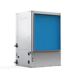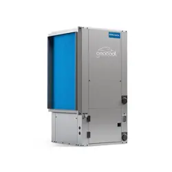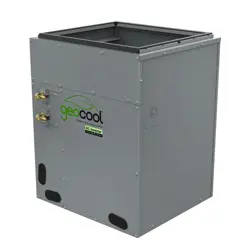

GeoCool® DC Inverter
Geothermal Heat Pump
SERVICE MANUAL
Version Date: 09/15/23
Capacity: 48kBtu/h 60kBtu/h
Rate Frequency: 60H
z
Operating Range:
Cooling: 44.6°F (7°C) ~107.6°F (42°C)
Heating: 21.2°F (-6°C) ~89.6°F (32°C)
Foreword
Thank you for choosing this product. In order to correctly install and use our units, and for the satisfactory
operation effect, please read this manual carefully.
This manual specifies safe operation requirements from perspectives of product introduction, control,
troubleshooting and maintenance, as well as basic principles and implementation methods. Professional
operators must abide by relevant national (local) safety requirements and technical specifications set forth in
this manual during operations; otherwise, the product system may fail or be damaged, and personnel safety
accident may also occur.
Safety Notice
Before using this product, please first read the instruction manual.
Before installing this product, please first read the instruction manual.
Before repairing this product, please first read the technical service manual.

CONTENTS
Safety Notice on Maintenance ................................................. 1
Safety Notice on Operation ................................................... 2
1 Product Introduction ....................................................... 3
1.1 Lists of Units .................................................................... 3
1.2 Electrical Parameters ............................................................. 4
2 Control Mode .............................................................. 4
2.1 Based Control ................................................................... 4
2.2 Special Control .................................................................. 5
3 Functions ................................................................. 7
3.1 Dip Switch Setting of Compressor Module ........................................... 7
3.2 Dip Switch Setting of A-Coil Module ................................................ 7
3.3 Refrigerant Recovery ............................................................. 9
3.4 Water Pump Start-up Function ..................................................... 9
4 Power Distribution ........................................................ 10
4.1 Diagram of Power Distribution .................................................... 10
4.2 Wiring Diagrams ................................................................ 10
4.3 PCB Layout .................................................................... 13
4.4 Error Code ..................................................................... 17
4.4 Troubleshooting ................................................................ 18
4.5 Failures Not Caused by Errors .................................................... 44
5 Maintenance .............................................................. 46
5.1 System Diagram ................................................................ 46
5.2 Connection Pipe Vacuum Pumping ................................................ 46
5.3 Refrigerant Charging ............................................................ 48
5.4 Maintenance of Major Components ................................................ 50
5.5 Removal of Major Components ................................................... 58
5.6 Explosive View and Lists of Parts ................................................. 88
5 COMMON PARAMETER LISTS .............................................. 97
5.1 Temperature/Pressure List of Refrigerant ........................................... 97
5.2 Resistance / Temperature Lists of Temperature Sensors .............................. 98
6 Operation Tools .......................................................... 104

MRCOOL® DC INVERTER GEOTHERMAL HEAT PUMP
1
Safety Notice on Maintenance
PROHIBITED
:
(1) Do not pierce or burn.
(2) Please note that refrigerant may be odorless.
(3) The appliance shall be stored in a room without continuously operating ignition sources (For example:
open flames, an operating gas appliance or an operating electric heater).
(4) The installation method is the same with the common joints. However, because the joint can’t be detached,
if it is badly connected and causes leakage, it needs to be cut and replaced by a new one through welding.
(5) Using unsuitable parts or tools may lead to electric shock or fire hazard.
(6) If refrigerant leaks during maintenance, please ventilate the room immediately. Heavy leakage may lead to
breathing difficulty, severe injury or death.
(7) Disconnect power before disassembling the appliance for maintenance.
(8) The appliance should be maintained and cared by authorized technical personnel with necessary
qualifications.
WARNING:
(1) If the working place is more than 6.5 ft (2m's) high, please wear a safety helmet, gloves and a safety belt.
(2) Never mix any other substances except the specified refrigerant into the refrigerant circuit.
(3) When re-locating the appliance, check whether the new location is strong enough to withstand the weight
of the appliance.
(4) If there is refrigerant leak, please fix the leak before charging in the refrigerant. After refrigerant is charged,
check for refrigerant leaks. If you cannot spot the leak, stop the maintenance work. Please evacuate the
system and close the service valve to prevent refrigerant leaking into the room.
(5) Prepare suitable tools and protectors.
(6) If you need to carry out maintenance or check the electric circuit without cutting off the power, please be
careful not to touch the electrical parts.
NOTICE:
(1) If the appliance is maintained at a humid place, it should be grounded to avoid electric shock.
(2) Never repair the unit with wet hands. Operating the unit with wet hands may lead to electric shock.
(3) If the unit is not correctly grounded, please check and fix it.
(4) Before cleaning the unit, please disconnect power to prevent the inner fan from starting up and running at
high speed; Otherwise personal injury may occur.

MRCOOL® DC INVERTER GEOTHERMAL HEAT PUMP
2
(5) Measure the insulation resistance after maintenance. The resistance must be 3 ft (1M or higher. Bad
insulation may lead to electric shock.
(6) Welding and cutting work must be done in a well-ventilated place.
(7) Gas appliances, heaters and other fire sources should be kept away from the installation and maintenance
site.
(8) Maintenance should be done according to suggestions of the manufacturer.
(9) Maintenance should be done only after the refrigerant is completely reclaimed from the unit.
OBSERVED
:
(1) After the maintenance work is done, check the drainage of A-Coil Module.
(2) Do not tilt the unit, otherwise, water may spill out from the unit and make the floor and furniture wet.
(3) Disassembly of the unit, handling of the refrigerant, oil and accessories should all be done according to
applicable local rules and regulations.
Safety Notice on Operation
PROHIBITED:
(1) Never try to modify the unit, otherwise, it may cause electric shock, overheat or fire hazard.
(2) If the power cord or conducting wires are scratched, please replace them.
(3) Never use connected or extended power cord or share the power socket with other appliances.
(4) Prepare a specialized power circuit for the appliance.
WARNING:
(1) If the power plug is dirty, please clean it before inserting it to the power socket. If the power plug is loose,
please tight it up.
(2) Do not damage the power cord. A damaged or refitted power cord may lead to electric shock or fire hazard.
(3) Check frequently whether the appliance is in good condition.
NOTICE:
(1) Do not use organic solvents to wipe the controller operating panel.
(2) Before cleaning the unit, cut off the power supply.
MRCOOL® DC INVERTER GEOTHERMAL HEAT PUMP
3
1 Product Introduction
1.1 Lists of Units
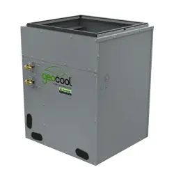
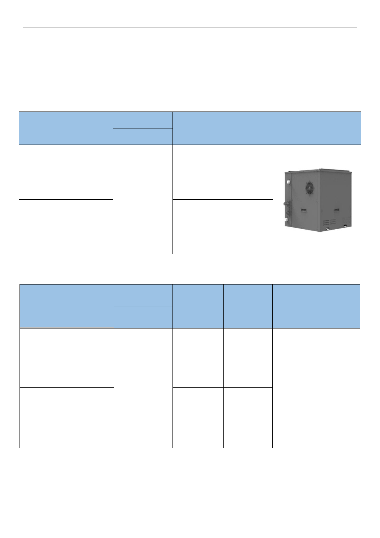
1.1.1 List of Compressor Module
Model
Power Supply
Cooling/Heating
Capacity (Btu/h)
Finished
Product Code
Appearance
V/Ph/Hz
GCSHPM060IN
208/230V-1Ph-60Hz
62000/55000
ES80100010
GCSHPM048IN
50500/48000
ES80100020
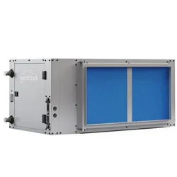
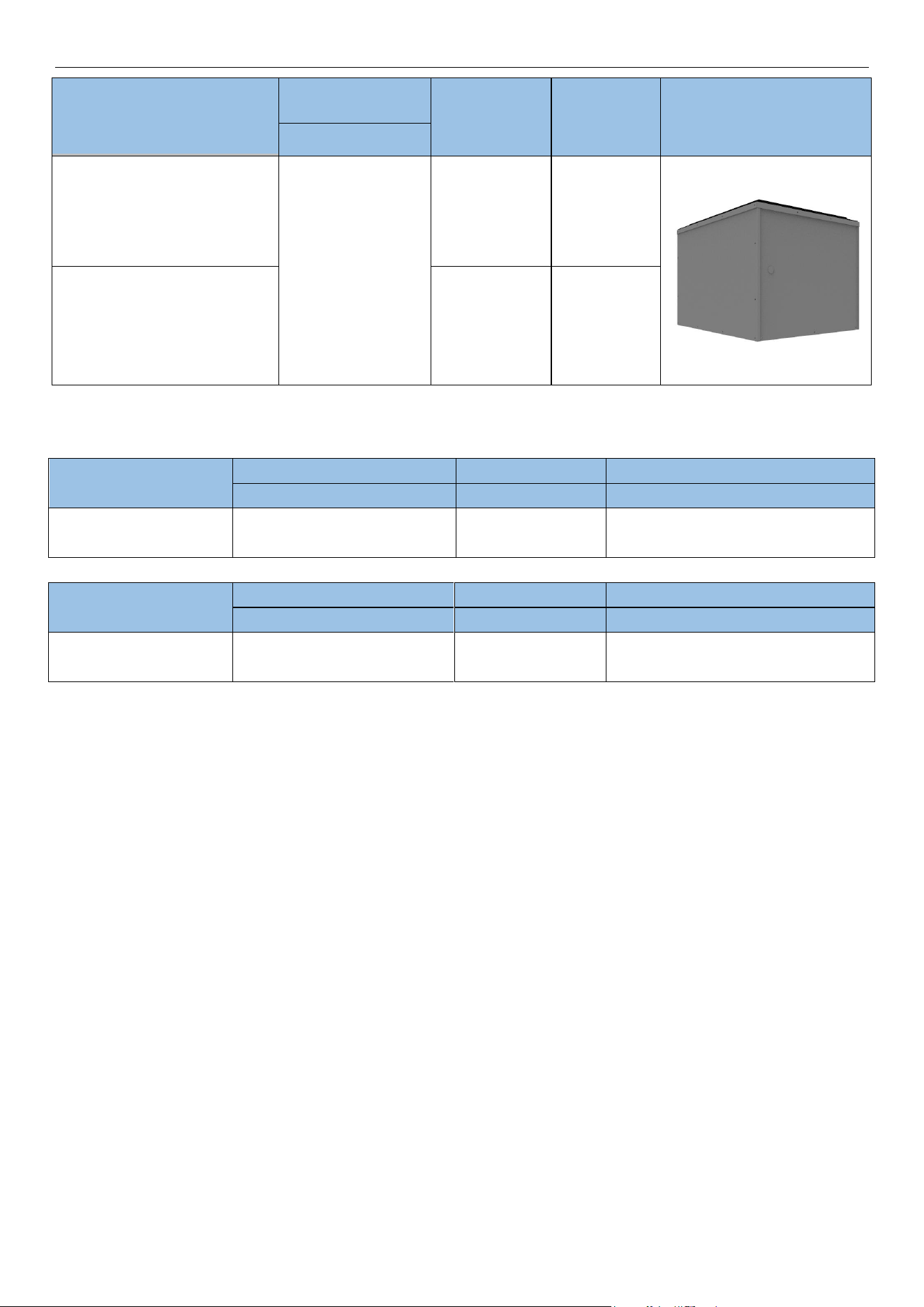
1.1.2 List of A-Coil Module
Model
Power Supply
Cooling/Heating
Capacity (Btu/h)
Finished
Product Code
Appearance
V/Ph/Hz
GCSCAM060GN
208/230V-1Ph-60Hz
62000/55000
ES82000010
GCSCAM048GN
50500/48000
ES82000020
NOTE:
1 Ton =
12000Btu
/h = 3.517kW
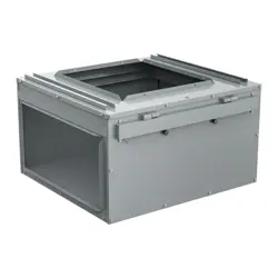
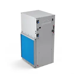
1.1.3 List of Blower Module
MRCOOL® DC INVERTER GEOTHERMAL HEAT PUMP
4
Model
Power Supply
Airflow (CFM)
Finished
Product Code
Appearance
V/Ph/Hz
GCSBLM014
208/230V-1Ph-60Hz
1400
ES81000010
GCSBLM013
1400
ES81000020
1.2 Electrical Parameters
Model
Power supply
Fuse Capacity
Circuit breaker capacity
V/Ph/Hz
A
A
GCSHPM048IN
GCSHPM060IN
208/230V-1Ph-60Hz
3.15
35
Model
Power Supply
Fuse Capacity
Circuit Breaker Capacity
V/Ph/Hz
A
A
GCSCAM048GN
GCSCAM060GN
208/230V-1Ph-60Hz
5
15
2 Control Mode
2.1 Based Control
2.1.1 Compressor Control
When cooling or heating mode is turned on, the fan of Blower module will run for a while before the
compressor starts. Under different modes, the compressor can only be stopped after running for some time
(special cases excluded). This is to protect the compressor from frequent start or stop. Once the compressor is
stopped, it must not be restarted right away. Please wait for a few minutes.
2.1.2 EEV Control
When the unit is first started, the electronic expansion valve will reset control. During the process, the
expansion valve will produce rattling sound. When cooling or heating mode is turned on, the valve will be open at
a certain step before the compressor starts.

MRCOOL® DC INVERTER GEOTHERMAL HEAT PUMP
5
2.1.3 4-way Valve Control
After heating mode is turned on for a while, 4-way valve will be energized to change the direction of
refrigerant flow so that the system can run in heating. Under other modes, the valve will not be energized.
To avoid the 4-way valve from incorrectly changing directions, when the unit stops in heating, due to a
temperature point or other protection reasons, the 4-way valve will continue to energized temporarily and lose
power after a while.
There must be enough pressure difference between the condensing and evaporation pressure for the 4-way
valve before changing directions.
2.2 Special Control
2.2.1 Oil Return Control
If the unit is running at low frequency for a long time, oil return control is needed to let the oil in the pipeline
back to the compressor. Generally, this control will take 4~6min. The compressor frequency will be raised.
2.2.1 High-Pressure Protection
If the high pressure switch of the unit is detected to trip at 4.2MPa or if the high pressure temperature
measured by high pressure sensor exceeds 149°F (65
℃)
for a period of time, the mainboard display screen will
display error code "E1" and the unit will shut down. High-Pressure Protection can be cleared by manually
powering off the unit. The reset pressure of the high pressure switch is 3.6MPa.
2.2.3 Low Pressure Protection Control
There are two low pressure switches for the unit. One is for ground water application designed to trip at
0.25MPa (reset at 0.3MPa), the other is for ground-loop application designed to trip at 0.1Mpa (reset at 0.2MPa).
When the low pressure switch is detected to trip for a period of time, the unit will shut down and the
mainboard display screen will display error code E3. The unit will restart when the low pressure switch has reset
within a few minutes. If low pressure protection occurs for several times in a short time, the unit will not restart
automatically. You need to restart the unit manually.

MRCOOL® DC INVERTER GEOTHERMAL HEAT PUMP
6
2.2.4 High Discharge Temperature Protection
If the discharge temperature of the unit is detected to be higher than 230°F (110
℃)
for a period of time,
the unit shuts down and displays error code "E4" on the main board display screen. When it is detected that the
discharge temperature of the unit is less than the 194°F (90
℃)
for a period of time, the error will be cleared and
the unit will restart. If High Discharge Temperature Protection occurs multiple times within a certain period of
time, the error cannot be automatically cleared and need to be cleared manually by powering off the unit.
2.2.5 Anti-Freezing Protection
Under cooling mode, if the temperature of the evaporator (measured by the in-tube temperature sensor) is
detected to be lower than the limit value for a continuous period of time, the evaporator is at risk of frosting, the
unit will enter Anti-Freezing Protection and shut down. If the temperature of the evaporator is detected to
be higher than the relating value for a period of time, the unit will restart. If the anti-freezing protection
occurs multiple times during a period of time in the cooling mode, the unit will stop and the error code "E2"
will be displayed on the main board display screen and the error need to be cleared by manually powering off
the unit.
For ground water application, if the compressor is not operating and the inlet or outlet water temperature of the
Compressor module is below 33.8°F (1
℃), water valve will open and the water pump will start to circulate the
water in the water loop. The error code "E2" will display on the main board display screen. If the water
temperature is higher than 41°F (5℃) for a period of time, the anti-freezing protection will be cleared. The water
pump will shut down and water valve will close.

MRCOOL® DC INVERTER GEOTHERMAL HEAT PUMP
7
3 Functions
3.1 Dip Switch Setting of Compressor Module
3.1.1 Geothermal Mode Setting
The geothermal application of the unit can be set through the second dip switch SA2 on the mainboard of
the Compressor module. The specific definitions of the dip switch are as follows.
Model
Geothermal
Application
Dip switches of Compressor Module
GCSHPM048IN
GCSHPM060IN
Ground Water
(Default)
Ground Loop
3.2 Dip Switch Setting of A-Coil Module
3.2.1 Fan Speed Setting
Set the fan speed through the dip switch SA1 of the A-Coil Module mainboard
and you can change the fan
speed by the first dip switch of the SA1. For the automatic adjustment control, the fan speed will change
according to the temperature of return air temperature. For fixed speed control, the fan will run at a certain level.
The specific definition of the dip switch is as follows.
Model
DIP Switch
Speed Control
Dip switches of A-Coil Module
GCSCAM048GN
GCSCAM060GN
The first dip switch
of the SA1
Automatic
Adjustment Control
Fixed Speed Control

MRCOOL® DC INVERTER GEOTHERMAL HEAT PUMP
8
Model
Dip Switch
Fan Speed
Dip switches of A-Coil Module
GCSCAM048GN
GCSCAM060GN
SA1
Level 1
Level 2
Level 3
(Default)
Level 4
Level 5
3.2.2 Supply Air Direction Setting
The supply air direction of the unit need to be set through the second dip switch of SA2 on the mainboard of
the A-Coil module according to the installation of the unit. The specific definition of the dip switch is as follows.
Model
Air flow directions
Dip switches of A-Coil Module
GCSCAM048GN
GCSCAM060GN
Vertical Upflow/
Horizontal Return Air
(Default)
Vertical Downflow
NOTE:
①
During installation and debugging, pay attention to check whether the thermostat has set the fan delay and
shutdown time. The actual delay and shutdown time of the fan depends on the setting of the thermostat.

MRCOOL® DC INVERTER GEOTHERMAL HEAT PUMP
9
3.3 Refrigerant Recovery
This function is part of the debugging function. It is only used for the situation that the unit would be removed
to another place and the refrigerant need to be recovered to the unit from the pipelines.
When the unit is shut down, the debugging function can be enabled by the operation of SW1-3.
1. Press and hold "SW1" for about 5 seconds to enter the first level menu of debug menu.
2. Under the first level menu, press and hold "SW1" for about 5 seconds to switch to the number "08".
3. Press and hold "SW2" or "SW3" for about 5 seconds to enter the control mode. "ON" means on, and
"OF" means off.
4. Press and hold "SW1" for about 5 seconds to save.
Notes: When operating by pressing SW1~3, please maintain the button operation until the display screen
changes. During debugging function, if no operation is performed within 10s, the debug menu interface will
exit.
3.4 Water Pump Start-up Function
This function is part of the debugging function. It is used for evacuating the air from the water pipeline for the
installation or maintenance of the water system. The water pump start-up function needs to be operated when
the unit is powered on, and must be operated by a professional. The water or antifreeze solution need to be
added at the same time.
When the unit is shut down, the debugging function can be enabled by the operation of SW1-3.
1. Press and hold "SW1" for about 5 seconds to enter the first-level menu of the debugging mode.
2. In the first-level menu, press and hold "SW1" for about 5 seconds to switch to the number "03".
3. Press and hold "SW2" or "SW3" for about 5 seconds to enter the control mode, "ON" means open, "OF"
means off.
4. Press and hold "SW1" for about 5 seconds to save.
Notes: When operating by pressing SW1~3, please keep pressing the keys until the display changes.
In this mode, the Water Flow Switch Protection is set to be reserved.
If no air discharges from the discharge valve in the water system, the air can be regarded as fully evacuation.
During debugging function, if no operation is performed within 10s, the debug menu interface will exit.
The limit time of this function is 30min. It will automatically exit and shut down the water pump.
MRCOOL® DC INVERTER GEOTHERMAL HEAT PUMP
10
4 Power Distribution
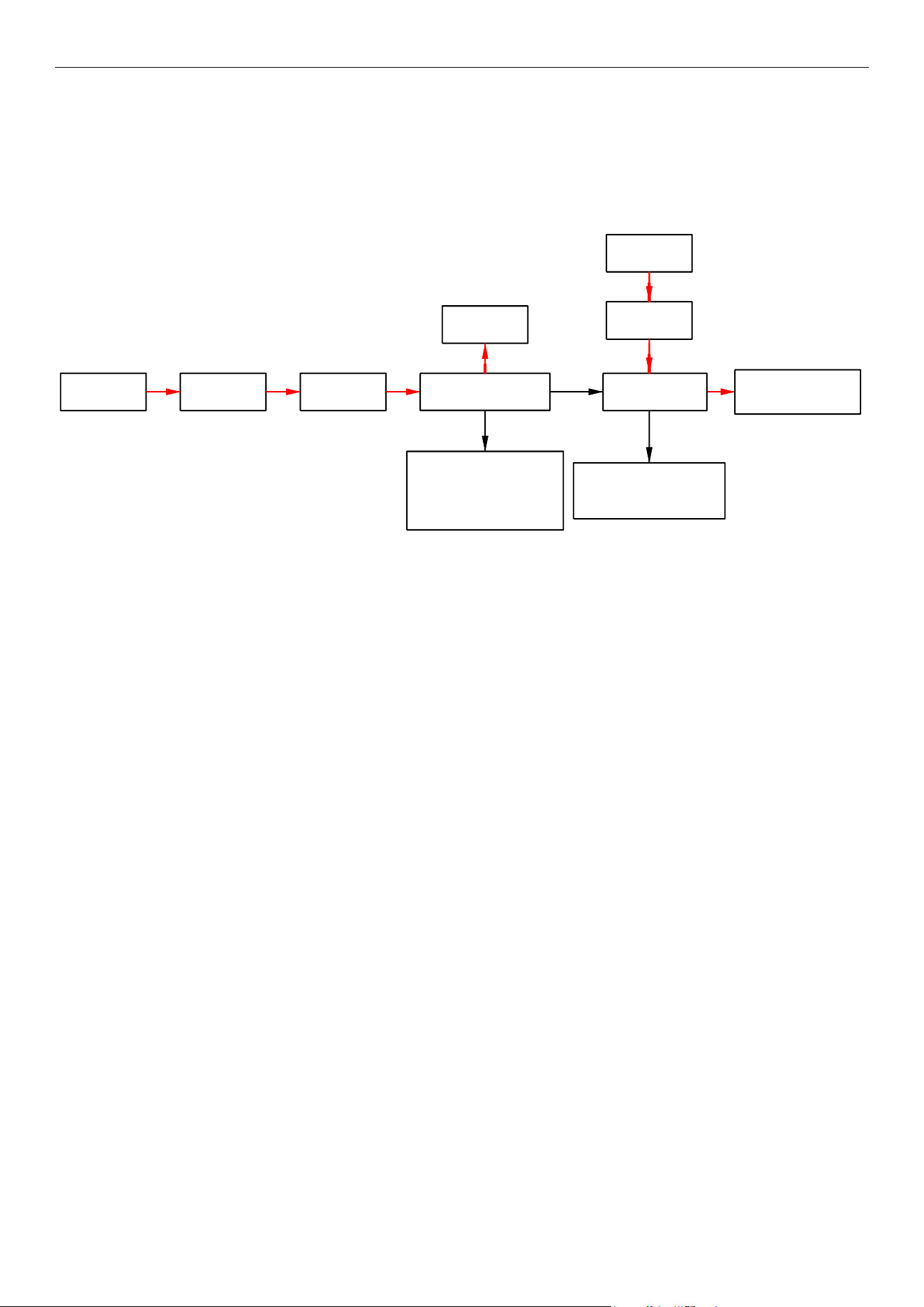
4.1 Diagram of Power Distribution
PowerPower supplysupply
AirAir switchswitch FilterFilter boardboard
MainMain boardboard ofof
CompressorCompressor ModuleModule
CompressorCompressor
MainMain boardboard ofof
A-CoilA-Coil ModuleModule
PowerPower supplysupply
AirAir switchswitch
ControlControl signalsignal ofof temperaturetemperature
sensor,sensor, 4-way4-way valve,valve, electronicelectronic
expansionexpansion valve,valve, highhigh andand lowlow
pressurepressure switch,switch, etc.etc.
ControlControl signalsignal ofof temperaturetemperature
sensor,sensor, electronicelectronic expansionexpansion
valve,valve, fan,fan, etc.etc.
A-CoilA-Coil ModuleModule andand
BlowerBlower ModuleModule
(The red line represents power line while black line represents the control line.)
4.2 Wiring Diagrams
The following electric diagram is for reference only. Please refer to diagram stuck on the unit as the latest
version.
4.2.1 Wiring Diagrams of Compressor Module
Model:
GCSHPM048IN / GCSHPM060IN

MRCOOL® DC INVERTER GEOTHERMAL HEAT PUMP
11

MRCOOL® DC INVERTER GEOTHERMAL HEAT PUMP
12
4.2.2 Wiring Diagrams of A-Coil Module
Model: GCSCAM048GN / GCSCAM060GN
MRCOOL® DC INVERTER GEOTHERMAL HEAT PUMP
13
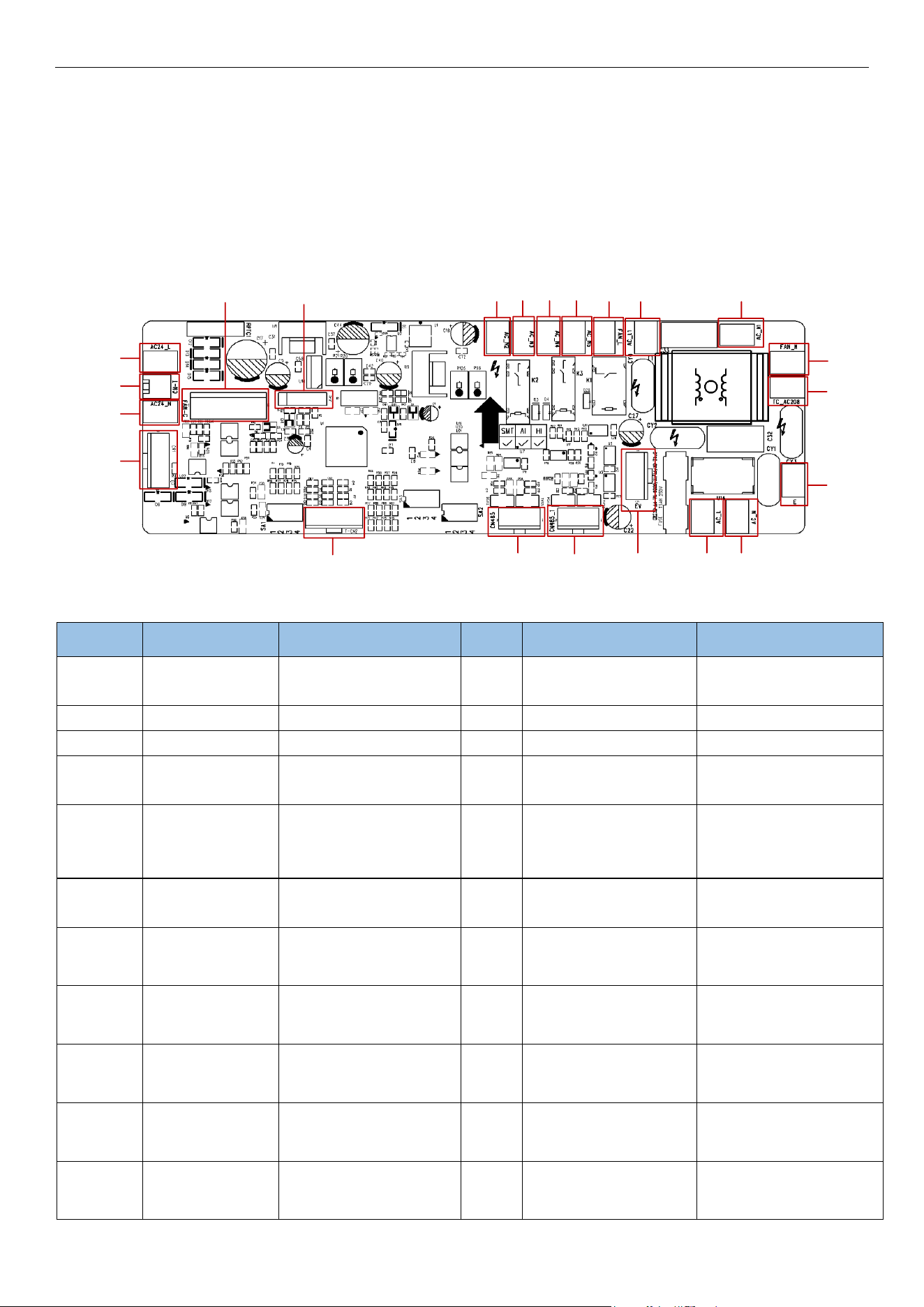
4.3 PCB Layout
4.3.1 Interface
A-Coil Module
:
Model:
GCSCAM048GN / GCSCAM060GN
1
2 3 4 5 76 8 9
10
11
12
131415161718
19
20
21
22
Mainboard
No.
Printing
Terminal
No.
Printing
Terminal
1
FAN_C
Motor control signal
terminal
12
E
Ground wire terminal
2
JTAG
Program terminal
13
AC_N
Neutral wire input
3
AC_N2
Reserved
14
AC_L
Live wire input
4
AC_N3
Reserved
15
EV
Electronic expansion valve
terminal
5
AC_N4
Reserved
16
CN485_1
485 Wired control
communication
interface(Reserved)
6
AC_N5
Reserved
17
CN485
485 Wired control
communication interface
7
FAN_L
Motor live wire input
18
T-CN2
Thermal pack interface
8
AC_L1
Transformer live wire input
(230V)
19
CN1
Thermostat control signal
terminal
9
AC_N1
Transformer neutral wire
input
20
AC24_N
Transformer neutral wire
output
10
FAN_N
Motor neutral wire input
21
CN-T
AC 24V
11
TC_AC208
Transformer live wire input
(208V)
22
AC24_L
Transformer live wire
output

MRCOOL® DC INVERTER GEOTHERMAL HEAT PUMP
14
Compressor Module
:
Model:
GCSHPM048IN / GCSHPM060IN
Mainboard
No.
Printing
Terminal
No.
Printing
Terminal
1
AC-L
Live wire input
2
AC-N
Neutral wire input
3
J3
Reserved
4
COMP
Compressor output
5
JTAG2
JTAG1
JTAG3
JTAG4
Wiring terminal
6
CN485-A1
CN485-A2
CN485-B1
CN485-B2
RS485 communication terminal
7
T-SENSOR1
1-2. Water inlet temperature sensor
8
T_SENSOR3
1-2. Suction temperature sensor

MRCOOL® DC INVERTER GEOTHERMAL HEAT PUMP
15
No.
Printing
Terminal
No.
Printing
Terminal
terminal
3-4. Water outlet temperature sensor
terminal
5-6. Liquid pipe temperature sensor
terminal
terminal
3-4. Discharge temperature sensor
terminal
9
T_SENSOR2
Reserved
10
FA1
Electronic expansion valve terminal
11
IN-SW1
Water flow switch
12
CN12
5V DC power supply input
13
H-PRESS
High pressure sensor terminal
14
HPP2
System high pressure protection
terminal
15
LPP2
System low pressure protection
terminal
16
LPP1
System low pressure protection
terminal
17
HPP2
System high pressure protection
terminal
18
FAN1
Fan terminal
19
WATER_PUMP
Reserved
20
PUMP-L
Water pump live wire input
21
PUMP-N
Water pump neutral wire input
22
4WAY
4-way valve
23
CN13
5V DC power supply output
Filtering Board:
Model:
GCSHPM048IN / GCSHPM060IN
No.
Printing
Terminal
No.
Printing
Terminal
1
N-OUT
Power output neutral wire terminal
2
PE
Filtering board ground wire terminal
3
N
Power input neutral wire terminal
4
AC-L
Power input live wire terminal
5
L-OUT
Power output live wire terminal

MRCOOL® DC INVERTER GEOTHERMAL HEAT PUMP
16
4.3.2 IPM, PFC Testing Method
4.3.2.1Method of Testing IPM Module
(1) Preparation before test: prepare a universal meter and turn to its diode option, and then remove the wires
U, V, W of the compressor after it is powered off for one minute.
(2) Testing Step
Step 1: put the black probe on the place P and the red one on the wiring terminal U, V, W respectively as
shown in the following figure to measure the voltage between UP, VP and WP.
Step 2: put the red probe on the place GND and the black one on the wiring terminal U, V, W respectively as
shown in the following figure to measure the voltage between NU, NV and NW.
(3) If the measured voltages between UP, VP, WP, NU, NV, NV are all among 0.3V-0.7V, then it indicates the
IPM module is normal; If any measured valve is 0, it indicates the IPM is damaged.
3.3.2.2 Method of Testing PFC Module Short Circuit
(1) Preparation before testing: Prepare a multimeter, then turn it on to the DC voltage mode. After powering
off for 20 minutes, remove the AC-L and N wires.
(2) Connect the red probe of the multimeter to P and the black probe to GND, confirm that the voltage is less
than 10V, and then turn the multimeter on to the diode position.
(3) Place the black probe at point P, and the red probe at points D8-2, D5-2, and D2-2, respectively. Then
measure the voltage between D8-2, D5-2, and D2-2 to P. If the voltage between D8-2 and P, D5-2 and P, D2-2
and P is between 0.3 and 0.7V, it indicates that diodes D8, D5, and D2 in the PFC circuit are normal. If the
measured value is 0, the PFC circuit is damaged.
(4) Place the red probe at the GND point and the black probe at Q9-2, Q10-2, and Q11-2, respectively, to
measure the voltage between GND point and Q9-2, Q10-2, and Q11-2. If the voltage value between GND point
and Q9-2, Q10-2, and Q11-2 is between 0.3 and 0.7V, it indicates that the MOS tubes Q9, Q10, and Q11 in the
PFC circuit are normal. If the measured value is 0, the PFC circuit is damaged.

MRCOOL® DC INVERTER GEOTHERMAL HEAT PUMP
17
4.4 Error Code
If error occurs during operation, LCD temperature display screen will show the error information. If several
errors occur at the same time, their corresponding error codes will be shown in turn. When error occurs, please
shut off the unit and send for professional personnel to repair. For example, E1 (as shown below) indicates high
pressure protection.
No.
Error code Error
1
E1
High-Pressure Protection
2
E2
Anti-Freezing Protection
3
E3
Low-Pressure Protection
4
E4
High Discharge Temperature Protection
5
EC
Water Flow Switch Protection
6
C6
Discharge Temperature Sensor Error
7
dc
Suction Temperature Sensor Error
8
FB
Water Inlet Temperature Sensor Error
9
FM
Water Outlet temperature Sensor Error
10
A7
Liquid Pipe Temperature Sensor Error
11
E0
Fan Error
GCSHPM048IN / GCSHPM060IN

MRCOOL® DC INVERTER GEOTHERMAL HEAT PUMP
18
No.
Error code
Error
12
C2
In-Tube Temperature Sensor Error
13
Cb
Gas Pipe Temperature Sensor Error
14
C1
Return Air Temperature Sensor Error
15
E6
Communication Error
16
LF
Power Protection
17
E5
Current Protection
18
H5
IPM Protection
19
HC
PFC Protection
20
P8
High Driver Module Temperature Protection
21
PL
DC Bus Under-Voltage Protection or DC Bus Voltage Drop Error
22
PH
DC Bus Over-Voltage Protection
23
PU
Charging Circuit Error
24
C9
Chip Error
25
H3
High-Pressure Sensor Error
26
LP
Capacity DIP Switch Setting Error
4.4 Troubleshooting
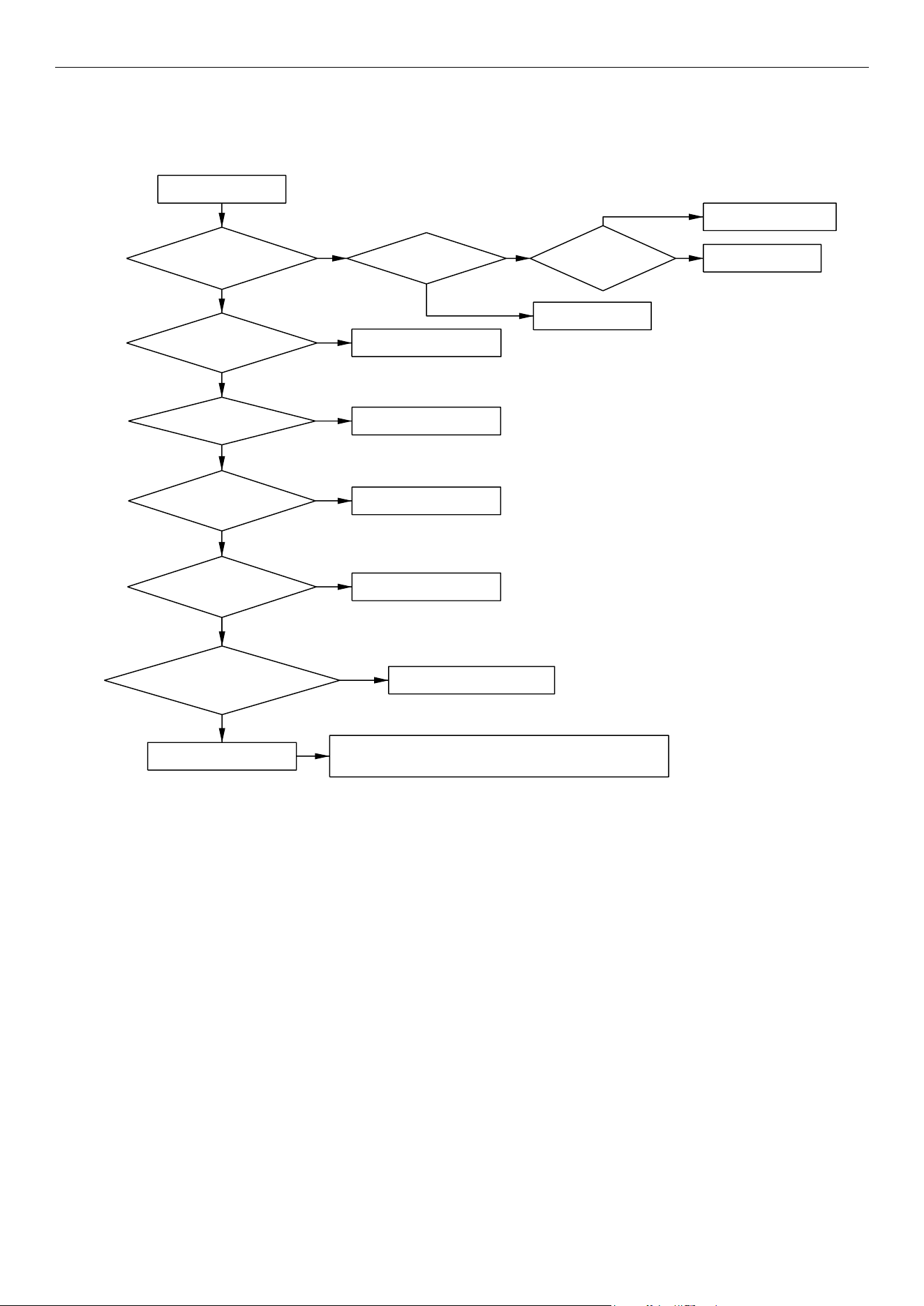
4.4.1 “E1” High-Pressure Protection
Error display:
Compressor Module mainboard LED display screen
Error judgment condition and method:
If the high pressure switch of the unit is detected to trip at 4.2MPa or if the high pressure temperature
measured by high pressure sensor exceeds 65
℃
for a period of time, the mainboard display screen will display
error code "E1" and the unit will shut down. High-Pressure Protection can be cleared by manually powering off
the unit. The reset pressure of the high pressure switch is 3.6MPa.
Possible reason
:
■Cut-off valve of Compressor module or A-Coil module is not fully opened;
■High-pressure switch or high pressure sensor is abnormal;
■Fan of Blower module is not working properly;
■Filter or air duct is blocked (heating mode);
■Refrigerant charging amount is too much;
■System pipeline is blocked
MRCOOL® DC INVERTER GEOTHERMAL HEAT PUMP
19
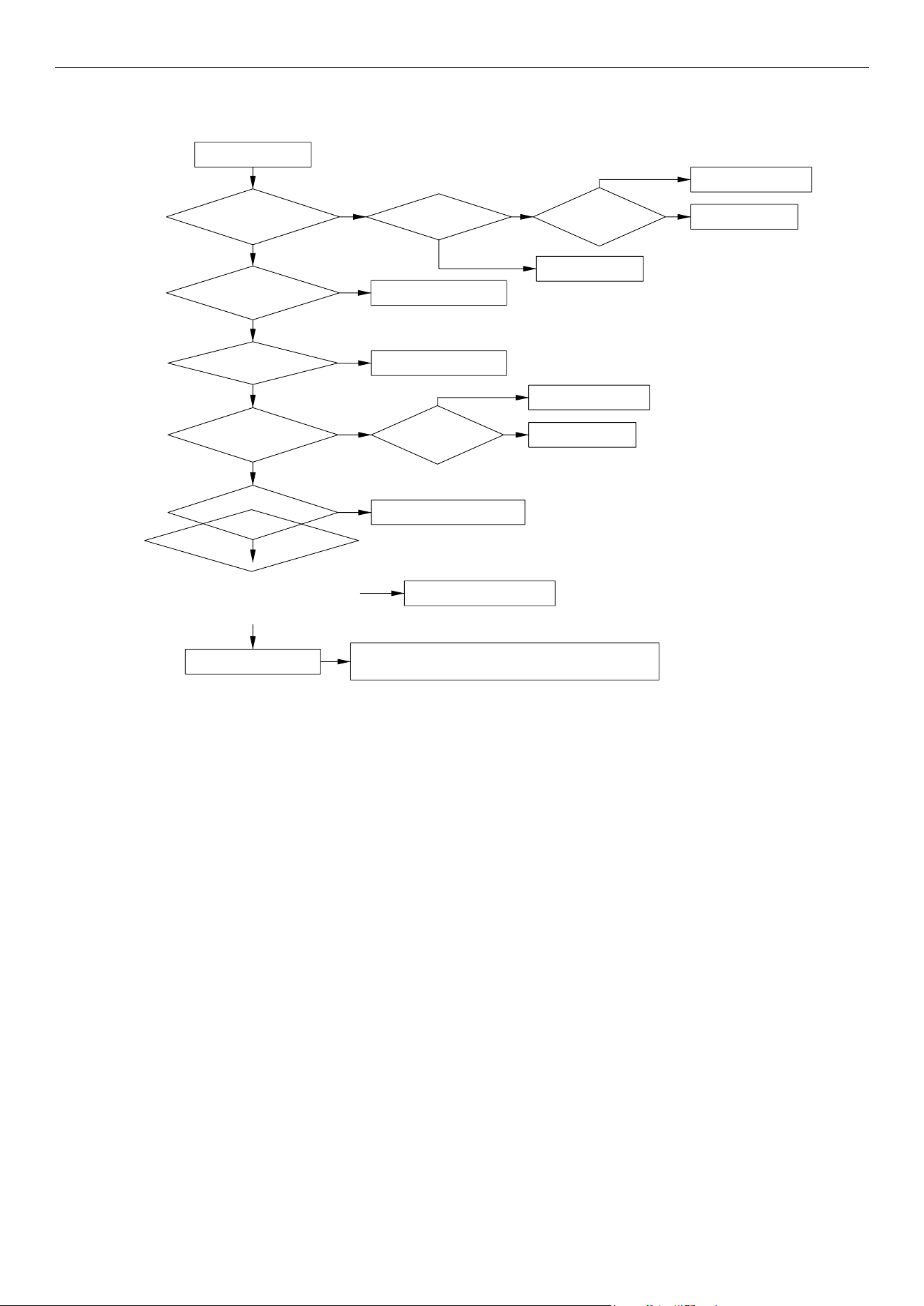
Heating Mode:
HighHigh pressurepressure protectionprotection
inin heatingheating modemode
CheckCheck thethe pressurepressure
withwith a manometer:manometer: isis itit
reallyreally high?high?
CheckCheck workwork
modemode ofof A-CoilA-Coil module:module:
doesdoes itit properlyproperly set?set?
CheckCheck thethe fanfan
ofof BlowerBlower modulemodule :
isis itit run?run?
CheckCheck thethe filterfilter andand heatheat
exchangeexchange fin:fin: isis therethere filthfilth
dirtydirty oror block?block?
RefrigerantRefrigerant pipepipe isis blockedblocked
ReferRefer toto MaintenanceMaintenance
MeasureMeasure thethe fanfan motormotor andand
signalsignal inputinput
RemoveRemove thethe barrierbarrier
CompletelyCompletely openopen thethe valvevalve
ReferRefer toto InstructionInstruction ManualManual
andand makemake itit properlyproperly setset
CheckCheck thethe
pressurepressure switchswitch :is:is itit
normal?normal?
ReplaceReplace thethe CompressorCompressor
modulemodule mainboardmainboard
ReplaceReplace thethe pressurepressure
switchswitch
NoNo
YesYes
CheckCheck thethe
highhigh pressurepressure sensor:sensor: isis
itit normal?normal?
ReplaceReplace thethe highhigh
pressurepressure sensorsensor
NoNo
MainlyMainly checkcheck thethe refrigerantrefrigerant pipe,pipe, filter,filter, capillarycapillary andand soso on.on.
CheckCheck thethe
flowflow ofof thethe inlet/outlet:inlet/outlet: isis
itit blocked?blocked?
CheckCheck thethe cut-offcut-off
valves:valves: areare theythey open?open?
YesYes
NoNo
NoNo
YesYes
YesYes
YesYes
YesYes
YesYes
NoNo
NoNo
NoNo
NoNo
YesYes
Troubleshooting
:
MRCOOL® DC INVERTER GEOTHERMAL HEAT PUMP
20
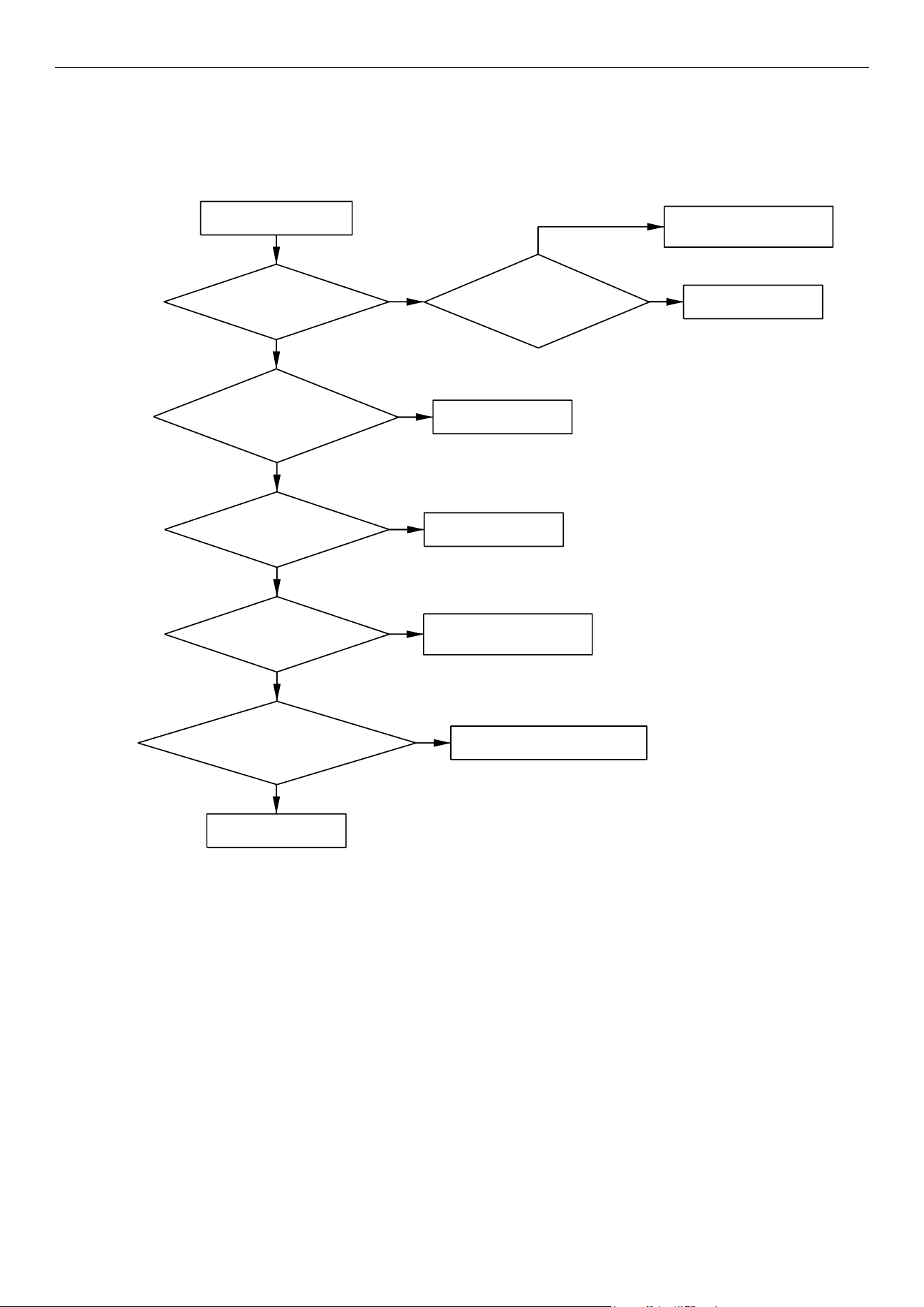
HighHigh pressurepressure protectionprotection
inin coolingcooling modemode
CheckCheck thethe pressurepressure
withwith a manometer:manometer: isis itit
reallyreally high?high?
CheckCheck workwork
modemode ofof A-CoilA-Coil module:module:
doesdoes itit properlyproperly set?set?
CheckCheck thethe co-axialco-axial heatheat
exchangerexchanger : isis itit filthfilth
blockage?blockage?
RefrigerantRefrigerant pipepipe isis blockedblocked
ReferRefer toto MaintenanceMaintenance
ChangeChange thethe valvevalve toto makemake waterwater
flowflow raterate withinwithin normalnormal rangerange
CompletelyCompletely openopen thethe valvevalve
ReferRefer toto InstructionInstruction ManualManual
andand makemake itit properlyproperly setset
CheckCheck thethe
pressurepressure switchswitch :is:is itit
normal?normal?
ReplaceReplace thethe CompressorCompressor
modulemodule mainboardmainboard
ReplaceReplace thethe pressurepressure
switchswitch
NoNo
YesYes
CheckCheck thethe
highhigh pressurepressure sensor:sensor: isis
itit normal?normal?
ReplaceReplace thethe highhigh
pressurepressure sensorsensor
NoNo
CheckCheck thethe
waterwater flowflow rate:rate: isis itit withinwithin
normalnormal range?range?
CheckCheck thethe cut-offcut-off
valves:valves: areare theythey open?open?
YesYes
NoNo
NoNo
YesYes
YesYes
YesYes
YesYes
NoNo
NoNo
NoNo
YesYes
CheckCheck thethe
waterwater pump:pump: dosedose itit properlyproperly
work?work?
YesYes
NoNo
ConnectConnect thethe waterwater pumppump
wireswires correctlycorrectly
CheckCheck ifif waterwater
pumppump wireswires areare correctlycorrectly
connectedconnected ?
ReplaceReplace thethe waterwater
pumppump
NoNo
YesYes
MainlyMainly checkcheck thethe refrigerantrefrigerant pipe,pipe, filter,filter, capillarycapillary andand soso on.on.
4.4.2 “E2” Anti-Freeze Protection
Error display:
Compressor Module mainboard LED display screen
Error judgment condition and method:
Under cooling mode, if the temperature of the evaporator (measured by the in-tube temperature sensor) is
detected to be lower than the limit value for a continuous period of time, the evaporator is at risk of frosting, the
unit will enter Anti-Freezing Protection and shut down. I
f the temperature of the evaporator is detected to be
higher than the relating value for a period of time, the unit will restart. If the anti-freezing protection occurs
multiple times during a period of time in the cooling mode, the unit will stop and the error code "E2" will be
displayed on the main board display screen and the error need to be cleared by manually powering off the unit.
For ground water application, if the compressor is not operating and the inlet or outlet water temperature of
the Compressor module is below 33.8°F (1
℃)
, water valve will open and the water pump will start to circulate
the water in the water loop. The error code "E2" will display on the main board display screen. If the water
temperature is higher than 41°F (5
℃)
for a period of time, the anti-freezing protection will be cleared. The water
pump will shut down and water valve will close.
Cooling Mode:
MRCOOL® DC INVERTER GEOTHERMAL HEAT PUMP
21
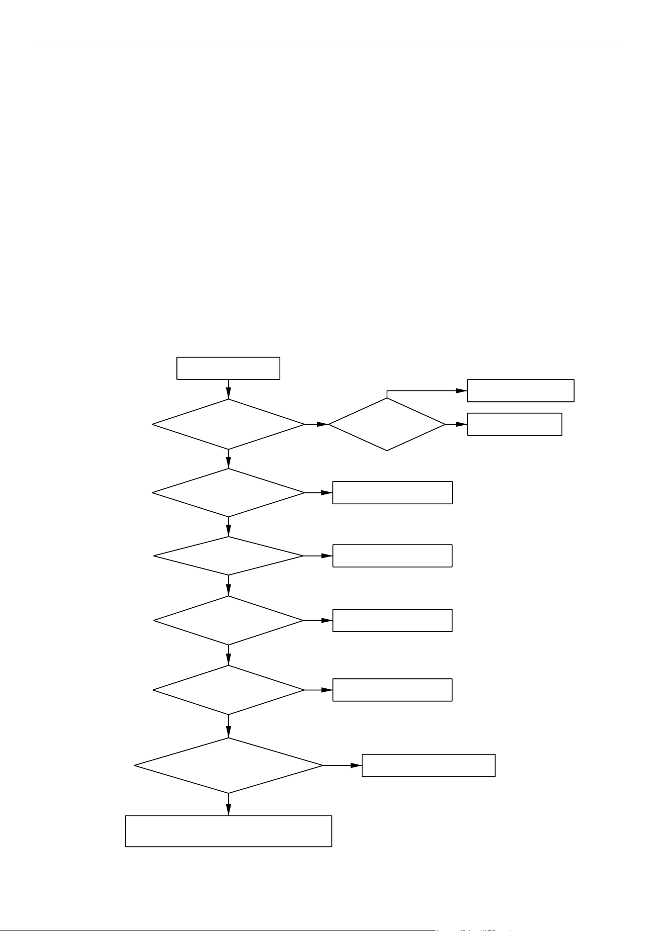
■Water inlet temperature is too low;
■Fan of Blower module is not working properly;
Troubleshooting
:
Anti-FreezingAnti-Freezing ProtectionProtection
CheckCheck
thethe compressorcompressor isis turnedturned offoff
beforebefore error,error, isis itit ?
CheckCheck thethe
waterwater temperaturetemperature isis lowerlower thanthan
1 CelsiusCelsius degreesdegrees
:is:is it?it?
NormalNormal protection,adjustprotection,adjust
thethe waterwater temperaturetemperature
NoNo
YesYes
NoNo
CheckCheck thethe mainmain boardboard
YesYes
YesYes
CheckCheck
thethe in-tubein-tube temperaturetemperature
oror gasgas temperaturetemperature isis lowerlower thanthan 5
CelsiusCelsius degreesdegrees
:is:is it?it?
NoNo
CheckCheck thethe mainmain boardboard
CheckCheck thethe fanfan ofof
BlowerBlower module:module: isis itit properlyproperly
work?work?
YesYes
NoNo
CheckCheck thethe motormotor
YesYes
CheckCheck thethe returnreturn airair
temperature:temperature: isis itit tootoo low?low?
YesYes
NormalNormal protectionprotection
NoNo
CheckCheck thethe heatheat
exchangerexchanger ofof A-CoilA-Coil module:module: isis itit filthfilth
blockage?blockage?
YesYes
ReferRefer toto CareCare andand MaintenanceMaintenance
NoNo
CheckCheck thethe mainmain boardboard
4.4.3 “E3” Low-Pressure Protection
Error display:
Compressor Module mainboard LED display screen
Error judgment condition and method:
There are two low pressure switches for the unit. One is for ground water application designed to trip at
0.25MPa (reset at 0.3MPa), the other is for ground-loop application designed to trip at 0.1Mpa (reset at 0.2MPa).
When the low pressure switch is detected to trip for a period of time, the unit will shut down and the
mainboard display screen will display error code E3. The unit will restart when the low pressure switch has reset
within a few minutes. If low pressure protection occurs for several times in a short time, the unit will not restart
automatically. You need to restart the unit manually.
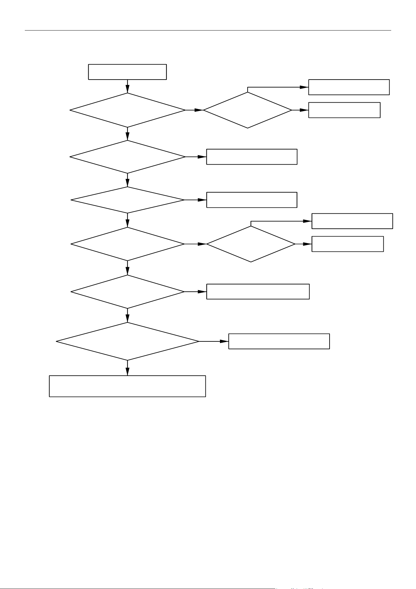
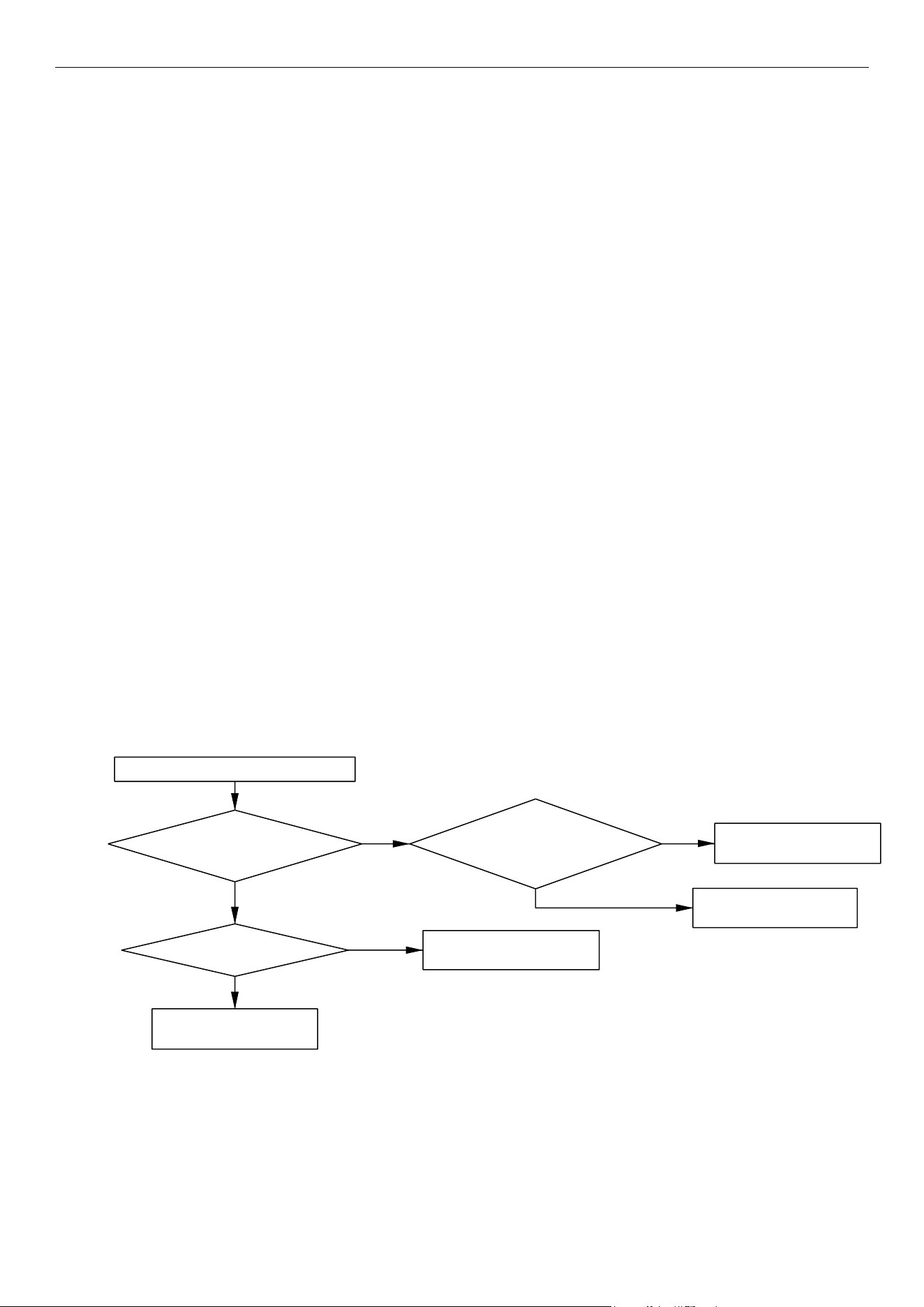
Possible reason
:
MRCOOL® DC INVERTER GEOTHERMAL HEAT PUMP
22
Possible reason
:
■Cut-off valve of Compressor module or A-Coil module is not fully opened;
■Dip switch of geothermal application on compressor module mainboard is wrong;
■Low-pressure switch is abnormal;
■Fan of Blower module is not working properly;
■Filter or air duct is blocked (cooling mode);
■Refrigerant charging amount is insufficient;
■System pipeline is blocked;
■Refrigerant leakage
Troubleshooting
:
Cooling Mode
LowLow pressurepressure protectionprotection
inin coolingcooling modemode
CheckCheck thethe pressurepressure
withwith a manometer:manometer: isis itit
reallyreally high?high?
CheckCheck workwork
modemode ofof A-CoilA-Coil module:module:
isis itit properlyproperly set?set?
CheckCheck thethe fanfan
ofof BlowerBlower modulemodule :
isis itit run?run?
CheckCheck thethe filterfilter andand heatheat
exchangeexchange fin:fin: isis therethere dirtydirty
oror block?block?
ReferRefer toto MaintenanceMaintenance
MeasureMeasure thethe fanfan motormotor andand
signalsignal inputinput
RemoveRemove thethe barrierbarrier
CompletelyCompletely openopen thethe valvevalve
ReferRefer toto InstructionInstruction ManualManual
andand makemake itit properlyproperly setset
NoNo
CheckCheck thethe
flowflow ofof thethe inlet/outlet:inlet/outlet: isis
itit blocked?blocked?
CheckCheck thethe cut-offcut-off
valves:valves: areare theythey open?open?
NoNo
YesYes
YesYes
YesYes
YesYes
YesYes
NoNo
NoNo
NoNo
NoNo
YesYes
ReplaceReplace thethe CompressorCompressor
modulemodule mainboardmainboard
CheckCheck thethe
highhigh pressurepressure sensor:sensor: isis
itit normal?normal?
ReplaceReplace thethe highhigh
pressurepressure sensorsensor
NoNo
YesYes
CheckCheck andand repairrepair thethe leakageleakage ofof thethe unit.unit. ChargeCharge
refrigerantrefrigerant accordingaccording toto thethe requiredrequired volumevolume
MRCOOL® DC INVERTER GEOTHERMAL HEAT PUMP
23
Heating Mode
LowLow pressurepressure protectionprotection
inin heatingheating modemode
CheckCheck thethe pressurepressure
withwith a manometer:manometer: isis itit
reallyreally high?high?
CheckCheck workwork
modemode ofof A-CoilA-Coil module:module:
isis itit properlyproperly set?set?
CheckCheck thethe co-axialco-axial heatheat
exchangerexchanger : isis itit filthfilth
blockage?blockage?
ReferRefer toto MaintenanceMaintenance
ChangeChange thethe valvevalve toto makemake waterwater
flowflow raterate withinwithin normalnormal rangerange
CompletelyCompletely openopen thethe valvevalve
ReferRefer toto InstructionInstruction ManualManual
andand makemake itit properlyproperly setset
ReplaceReplace thethe CompressorCompressor
modulemodule mainboardmainboard
NoNo
CheckCheck thethe
highhigh pressurepressure sensor:sensor: isis
itit normal?normal?
ReplaceReplace thethe highhigh
pressurepressure sensorsensor
NoNo
CheckCheck thethe
waterwater flowflow rate:rate: isis itit withinwithin
normalnormal range?range?
CheckCheck thethe cut-offcut-off
valves:valves: areare theythey open?open?
YesYes
NoNo
YesYes
YesYes
YesYes
YesYes
NoNo
NoNo
NoNo
YesYes
CheckCheck thethe
waterwater pump:pump: doesdoes itit properlyproperly
work?work?
YesYes
NoNo
ConnectConnect thethe waterwater pumppump
wireswires correctlycorrectly
CheckCheck ifif waterwater
pumppump wireswires areare correctlycorrectly
connectedconnected ?
ReplaceReplace thethe waterwater
pumppump
NoNo
YesYes
CheckCheck andand repairrepair thethe leakageleakage ofof thethe unit.unit. ChargeCharge
refrigerantrefrigerant accordingaccording toto thethe requiredrequired volumevolume
MRCOOL® DC INVERTER GEOTHERMAL HEAT PUMP
24
4.4.4 “E4” High Discharge Temperature Protection
Error display:
Compressor Module mainboard LED display screen
Error judgment condition and method:
If the discharge temperature of the unit is detected to be higher than 230°F (110
℃)
for a period of time, the unit
shuts down and displays error code "E4" on the main board display screen. When it is detected that the discharge
temperature of the unit is less than the 194°F (90
℃)
for a period of
time, the error will be cleared and the unit will
restart. If High Discharge Temperature Protection occurs multiple times within a certain period of time, the error
cannot be automatically cleared and need to be cleared manually by powering off the unit.
Possible reason
:
■Cut-off valve of Compressor module or A-Coil module is not fully opened;
■Electronic expansion valve is abnormal;
■Fan of Blower module is not working properly;
■Refrigerant charging amount is insufficient;
■System pipeline is blocked;
■Refrigerant leakage
Troubleshooting
:
HighHigh DischargeDischarge temperaturetemperature protectionprotection
MeasureMeasure thethe
dischargedischarge temperature:temperature: doesdoes itit havehave
reachedreached 110110℃?
ReplaceReplace thethe mainboardmainboard ofof
CompressorCompressor modulemodule
MeasureMeasure
resistanceresistance valuevalue ofof dischargedischarge
temperaturetemperature sensor:sensor: isis itit
correct(50KΩ)?correct(50KΩ)?
ReplaceReplace relevantrelevant dischargedischarge
temperaturetemperature sensorsensor
AreAre thethe
electronicelectronic expansionexpansion valvesvalves
broken?broken?
YesYes
ReplaceReplace relevantrelevant electronicelectronic
expansionexpansion valvevalve
NoNo
YesYes
YesYes
NoNo
NoNo
ReplaceReplace thethe mainboardmainboard ofof
CompressorCompressor modulemodule

MRCOOL® DC INVERTER GEOTHERMAL HEAT PUMP
25
4.4.5 “EC” Water Flow Switch Protection
Error display:
Compressor Module mainboard LED display screen
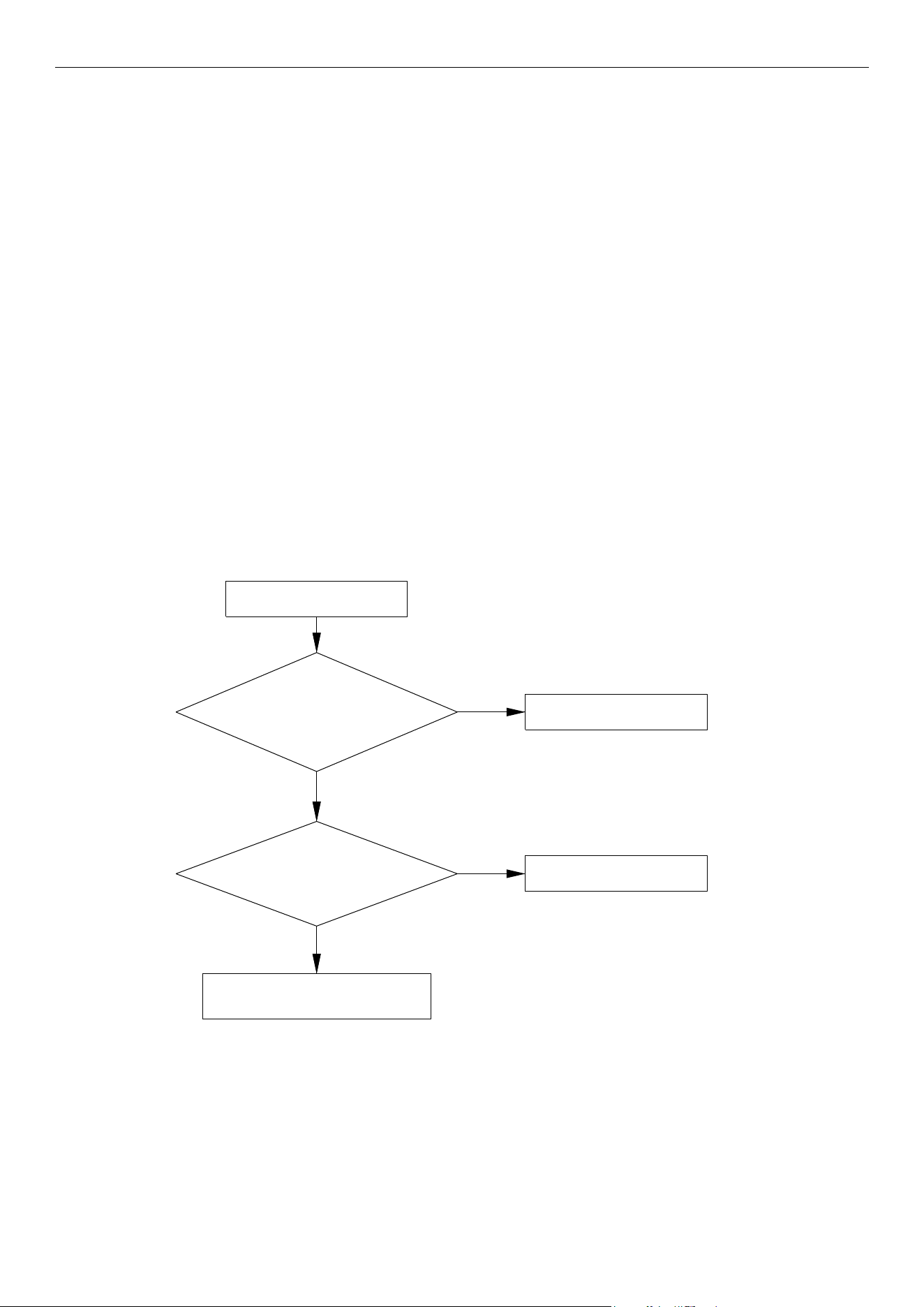
Error judgment condition and method:
If the water flow switch is detected for a continuous period of time, the system will enter Water Flow Switch
Protection. The error code "EC" will be displayed on the main board display screen, and the unit shuts down. The
error cannot be automatically cleared and can only be cleared through manual power off.
Possible reason:
■Insufficient water flow in the system
■Water flow switch signal line loosening
■Water flow switch target failure
WaterWater FlowFlow SwitchSwitch
ProtectionProtection
CheckCheck thethe waterwater
pumppump : isis itit properlyproperly
work?work?
CheckCheck thethe
waterwater pumppump powerpower supplysupply
wirewire isis orrectlyorrectly connectedconnected ,
isis itit ?
ConnectConnect thethe waterwater pumppump
powerpower supplysupply wirewire corrcetlycorrcetly
NoNo
YesYes
NoNo
ReplaceReplace thethe waterwater
pumppump
YesYes
YesYes
CheckCheck thethe waterwater
flowflow switchswitch : isis itit
reallyreally error?error?
CheckCheck thethe
filterfilter : isis itit filthfilth
blockage?blockage?
NoNo
CleanClean oror replacereplace thethe
filterfilter
YesYes
CheckCheck thethe
waterwater flowflow rate:rate: isis itit withinwithin
normalnormal range?range?
NoNo
NoNo
YesYes
CheckCheck thethe
waterwater flowflow switchswitch isis correctlycorrectly
connectedconnected toto thethe socketsocket onon
mainboard,mainboard, isis it?it? ?
CheckCheck thethe orientationorientation ofof
plugplug andand socketsocket
NoNo
YesYes
YesYes
ReplaceReplace thethe waterwater
flowflow switchswitch
AdjustAdjust thethe valvevalve angleangle
ComplementComplement thethe
waterwater
MRCOOL® DC INVERTER GEOTHERMAL HEAT PUMP
26
4.4.6 “C6” Discharge Temperature Sensor Error
Error display:
Compressor Module mainboard LED display screen
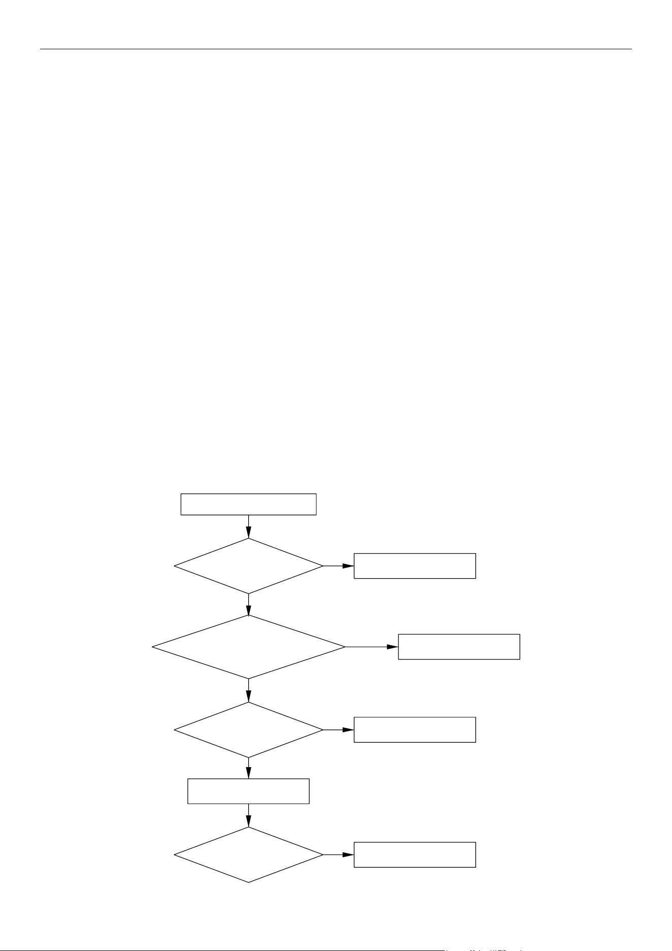
Error judgment condition and method:
The resistance value of discharge temperature sensor is 50 KΩ;
Sample the AD value of temperature sensor through temperature sensor detecting circuit and judge the
range of AD value, If the sampling AD value exceeds upper limit and lower limit in 5 seconds continuously,
report the error.
Possible reason:
■Poor connection between temperature sensor and terminal in mainboard
■Temperature sensor is abnormal
■Detecting circuit is abnormal
Troubleshooting
:
DischargeDischarge temperaturetemperature
sensorsensor errorerror
TheThe temperaturetemperature
sensorsensor isis correctlycorrectly
connectedconnected toto thethe socketsocket onon
mainboard,mainboard, isis it?it?
RemoveRemove thethe
temperaturetemperature andand measuremeasure itsits
resistanceresistance value:value: isis itit withinwithin
normalnormal range?range?
ReplaceReplace thethe mainboardmainboard ofof
compressorcompressor modulemodule
ConnectConnect thethe temperaturetemperature
sensorsensor corrcetlycorrcetly
ReplaceReplace thethe temperaturetemperature
sensorsensor
YesYes
NoNo
YesYes
NoNo
MRCOOL® DC INVERTER GEOTHERMAL HEAT PUMP
27
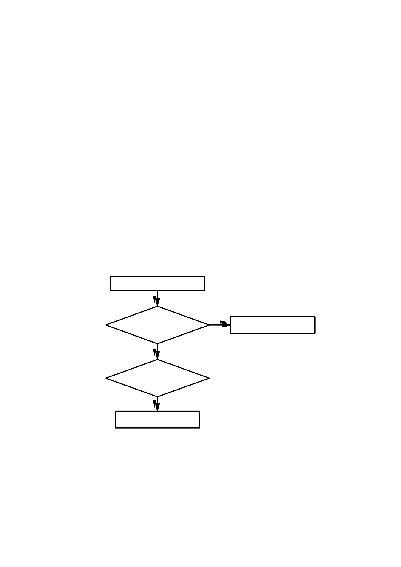
4.4.7 “H5” IPM Protection
Error display:
Compressor Module mainboard LED display screen
Error judgment condition and method:
When power is connected and drive chip received IPM lead that is of low level, then it is IPM module
malfunction. System will shut down for protection.
Possible reason:
■Compressor 3-phase wire connection is lack of phase or phase-reversed.
■System is overloaded and compressor current is too large.
■IPM module is damaged.
■IPM module’s 15V power supply is lower than 13.5V.
■6-line PWM signal and the corresponding element are abnormal.
■Compressor current sampling circuit element is damaged or drive chip current sampling AD terminal is
abnormal.
■Compressor is damaged.
Troubleshooting
:
IPMIPM ProtectionProtection
CompressorCompressor 3-phase3-phase wirewire
connectionconnection isis lacklack ofof phasephase oror
phase-reversingphase-reversing ?
SystemSystem isis
heavy-loaded?heavy-loaded? CompressorCompressor
currentcurrent isis tootoo large?large?
ConnectConnect wireswires accordingaccording toto
thethe phasephase sequencesequence
YesYes
YesYes
NoNo
NormalNormal protectionprotection
NoNo
YesYes
ReplaceReplace thethe mainmain boardboard
ErrorError stillstill exists?exists?
YesYes
ReplaceReplace thethe compressorcompressor
CheckCheck thethe fanfan
ofof thethe CompressorCompressor module:module:
isis itit properlyproperly work?work?
ReplaceReplace thethe fanfan ofof thethe
CompressorCompressor modulemodule
NoNo
YesYes
MRCOOL® DC INVERTER GEOTHERMAL HEAT PUMP
28
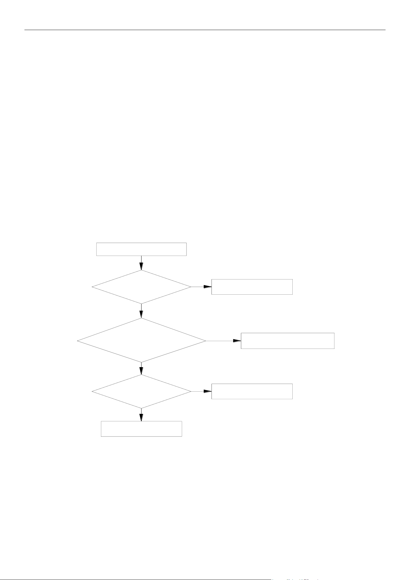
4.4.8 “HC” PFC Protection
Error display:
Compressor Module mainboard LED display screen
Error judgment condition and method:
After power is connected, and drive chip received PFC lead that is of low level, then it is PFC module
malfunction. System will shut down for protection.
Possible reason:
■Power grid voltage is abnormal.
■Main board PFC module is damaged.
■Main board PFC module’s 15V power supply is lower than 13.5V.
■Main board PWM signal for PFC and the corresponding element are abnormal.
■Main board PFC current sampling circuit element is damaged or drive chip current sampling AD terminal is
abnormal.
Troubleshooting
:
PFC Protection
Main board PFC is damaged?
Yes
No
Replace the main board
Check whether power grid
voltage is normal?
No
No
Normal protection
MRCOOL® DC INVERTER GEOTHERMAL HEAT PUMP
29
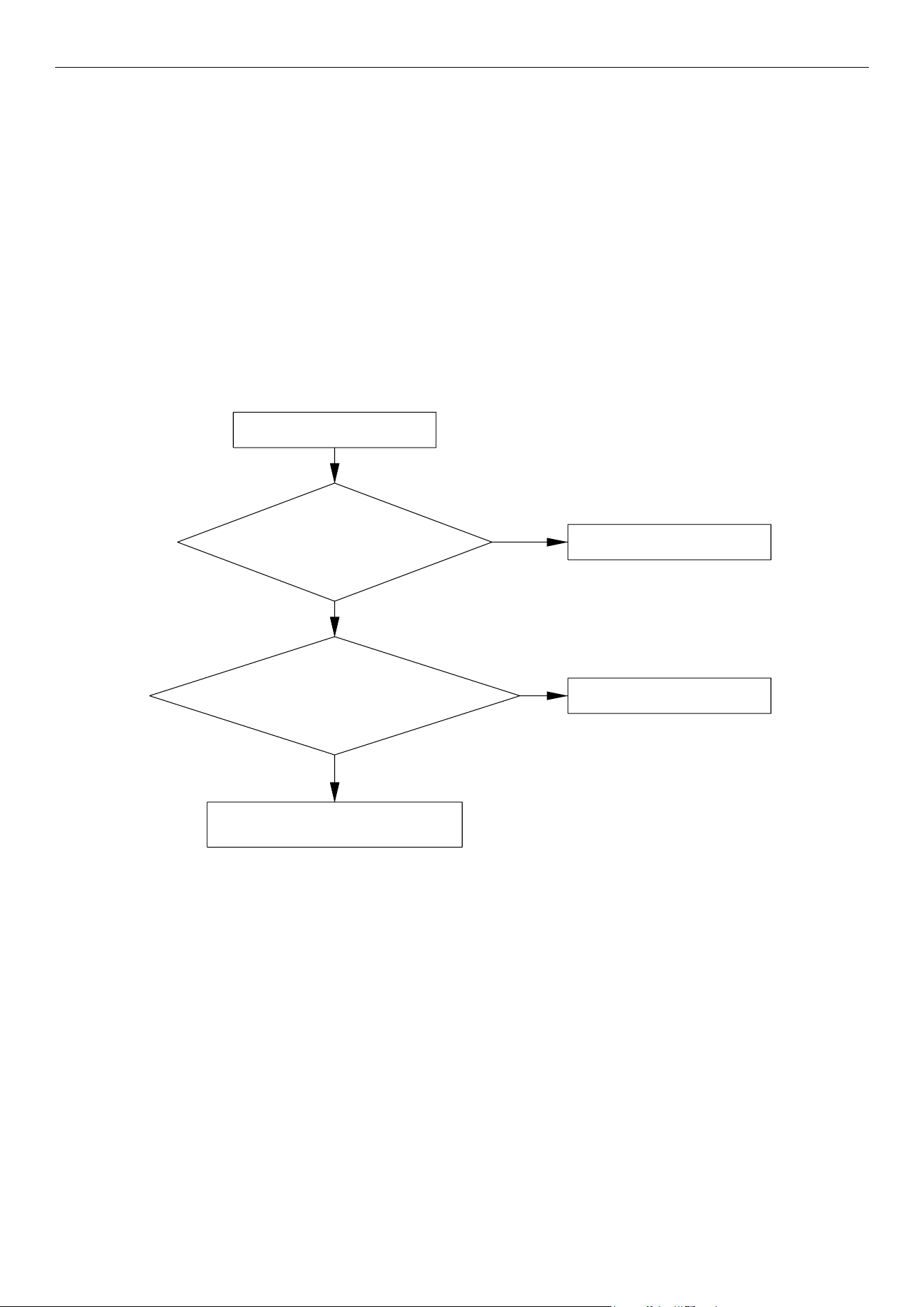
4.4.9 “P8” High Driver Module Temperature Protection
Error display:
Compressor module mainboard LED display screen
Error judgment condition and method:
If IPM module temperature exceeds the set protection value, then it can be judged that driver module
temperature is too high and system will shut down for protection.
Possible reason:
■Thermal grease is not applied or not evenly applied to the module, or there is other substance on the back of the
module.
■The module securing screws are not tightened up.
■Compressor module mainboard temperature sampling circuit element is damaged or drive chip temperature
sampling AD terminal is abnormal.
Troubleshooting
:
High Driver Module
Temperature Protection
Thermal
grease is not applied or not
evenly applied to the module? Is there
foreign matter on the back
of the module
The module securing
screws are note tightened?
Apply the thermal grease evenly.
Remove the foreign matter.
Yes
Yes
No
Tighten the screws
Yes
No
Replace the main board
Check the fan
of the Compressor module:
is it properly work?
Replace the fan of the
Compressor module
No
Yes
MRCOOL® DC INVERTER GEOTHERMAL HEAT PUMP
30
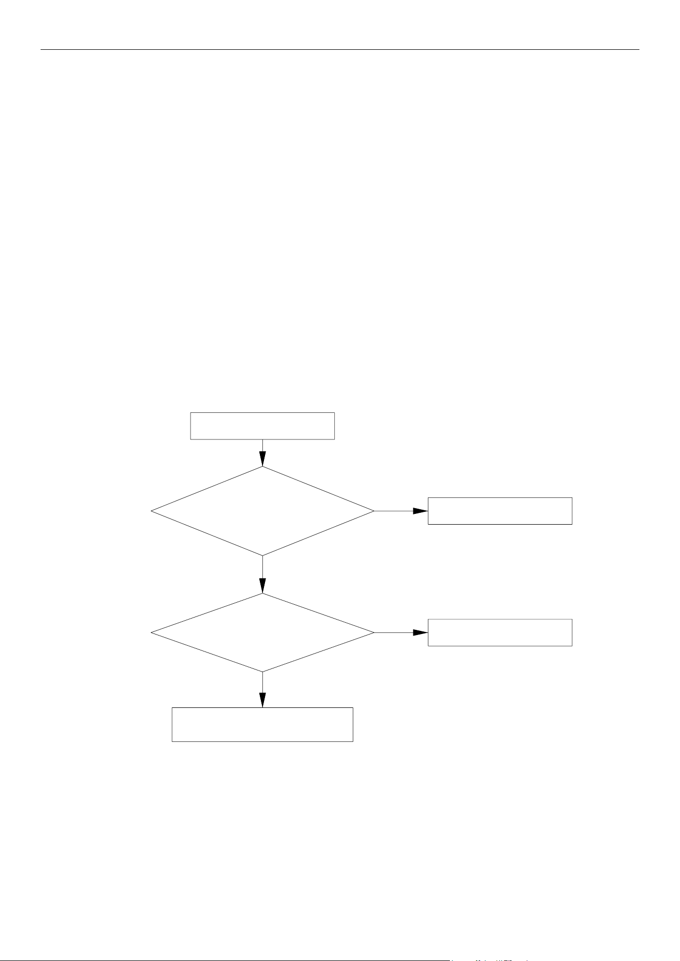
4.4.10 “H3” High-Pressure Sensor Error
Error display:
Compressor module mainboard LED display screen
Sample the AD value of pressure sensor through pressure sensor detecting circuit and judge the range of
AD value, If the sampling AD value exceeds upper limit and lower limit in 5 seconds continuously, report the error.
■Poor connection between pressure sensor and terminal in mainboard
■Pressure sensor is abnormal
■Detecting circuit is abnormal
Troubleshooting
:
PressurePressure sensorsensor errorerror
TheThe pressurepressure
sensorsensor isis correctlycorrectly
connectedconnected toto thethe socketsocket onon
mainboard,mainboard, isis it?it?
MeasureMeasure thethe
DCDC voltagevoltage valuevalue betweenbetween blackblack
lineline andand greengreen lineline ofof thethe sensor:sensor: isis itit
OK?(0.5~4.5V)OK?(0.5~4.5V)
ReplaceReplace thethe mainboardmainboard ofof
CompressorCompressor modulemodule
CheckCheck thethe orientationorientation ofof
plugplug andand socketsocket
ReplaceReplace thethe pressurepressure
sensorsensor
YesYes
NoNo
YesYes
NoNo
MRCOOL® DC INVERTER GEOTHERMAL HEAT PUMP
31
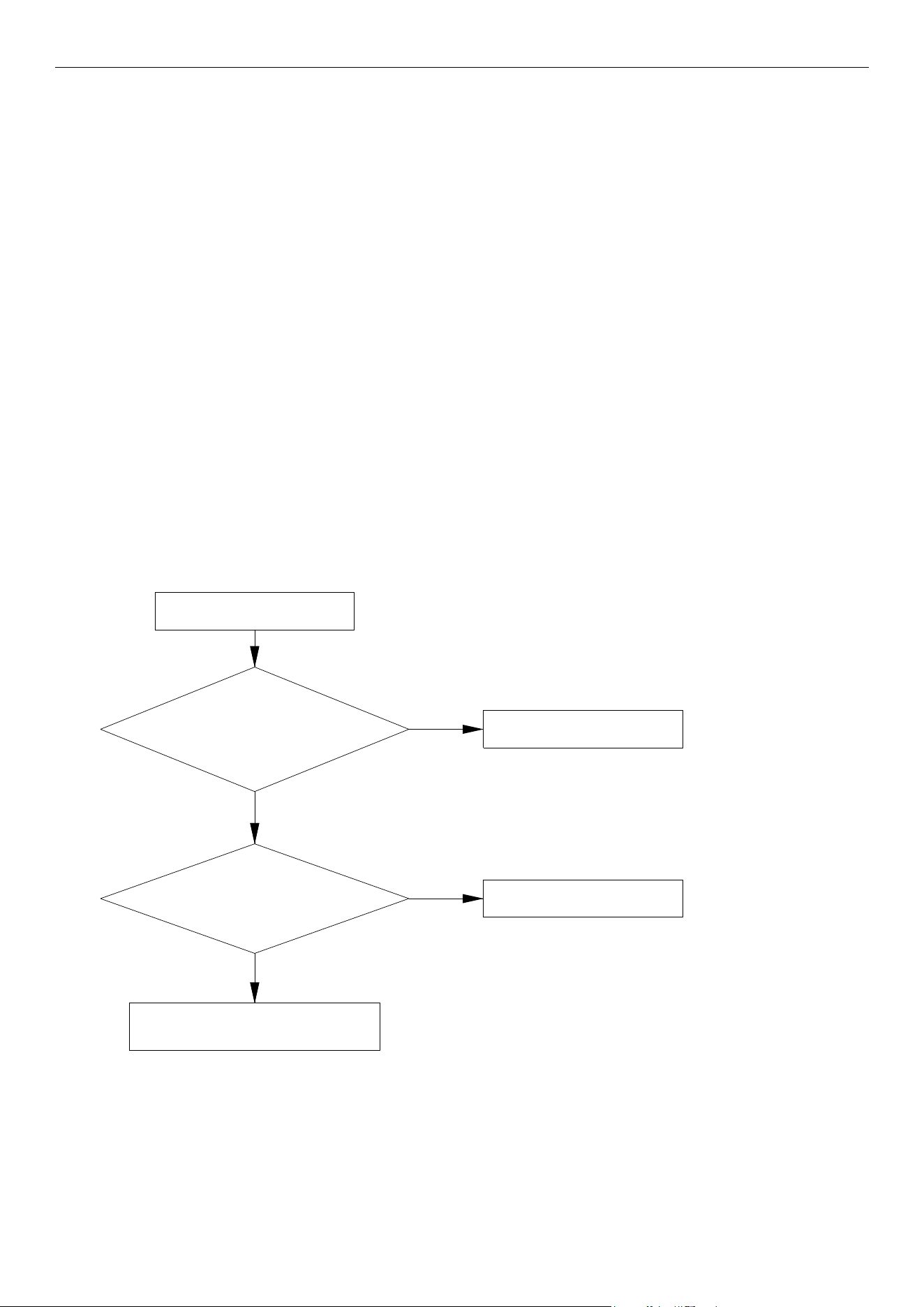
4.4.11 “dc” Suction Temperature Sensor Error
Error display:
Compressor module mainboard LED display screen
Error judgment condition and method:
The resistance value of suction temperature sensor is 20 KΩ;
Sample the AD value of temperature sensor through temperature sensor detecting circuit and judge the
range of AD value, If the sampling AD value exceeds upper limit and lower limit in 5 seconds continuously, report
the error.
Possible reason:
■Poor connection between temperature sensor and terminal in mainboard interface
■Temperature sensor is abnormal
■Detecting circuit is abnormal
Troubleshooting
:
SuctionSuction temperaturetemperature
sensorsensor errorerror
RemoveRemove thethe
temperaturetemperature andand measuremeasure itsits
resistanceresistance value:value: isis itit withinwithin
normalnormal range?range?
ReplaceReplace thethe mainboardmainboard ofof
compressorcompressor modulemodule
ReplaceReplace thethe temperaturetemperature
sensorsensor
YesYes
NoNo
YesYes
NoNo
TheThe temperaturetemperature
sensorsensor isis correctlycorrectly
connectedconnected toto thethe socketsocket onon
mainboard,mainboard, isis it?it?
ConnectConnect thethe temperaturetemperature
sensorsensor corrcetlycorrcetly
MRCOOL® DC INVERTER GEOTHERMAL HEAT PUMP
32
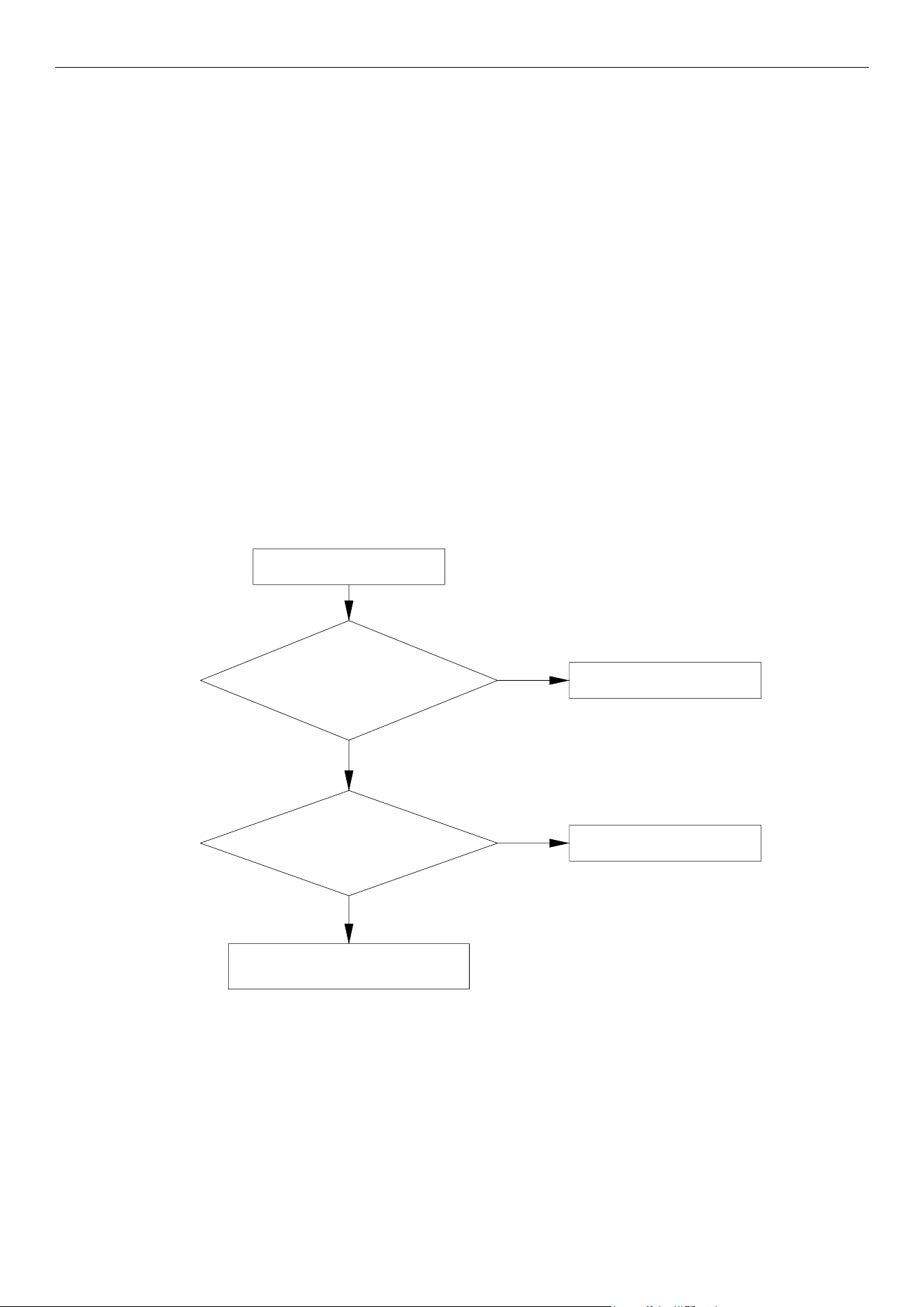
4.4.12 “FB” Water Inlet Temperature Sensor Error
Error display:
Compressor module mainboard LED display screen
Error judgment condition and method:
The resistance value of water inlet temperature sensor is 20 KΩ;
Sample the AD value of temperature sensor through temperature sensor detecting circuit and judge the
range of AD value, If the sampling AD value exceeds upper limit and lower limit in 5 seconds continuously, report
the error.
Possible reason:
■Poor connection between temperature sensor and terminal in mainboard interface
■Temperature sensor is abnormal
■Detecting circuit is abnormal
Troubleshooting:
WaterWater inletinlet temperaturetemperature
sensorsensor errorerror
RemoveRemove thethe
temperaturetemperature andand measuremeasure itsits
resistanceresistance value:value: isis itit withinwithin
normalnormal range?range?
ReplaceReplace thethe mainboardmainboard ofof
compressorcompressor modulemodule
ReplaceReplace thethe temperaturetemperature
sensorsensor
YesYes
NoNo
YesYes
NoNo
TheThe temperaturetemperature
sensorsensor isis correctlycorrectly
connectedconnected toto thethe socketsocket onon
mainboard,mainboard, isis it?it?
ConnectConnect thethe temperaturetemperature
sensorsensor corrcetlycorrcetly
MRCOOL® DC INVERTER GEOTHERMAL HEAT PUMP
33
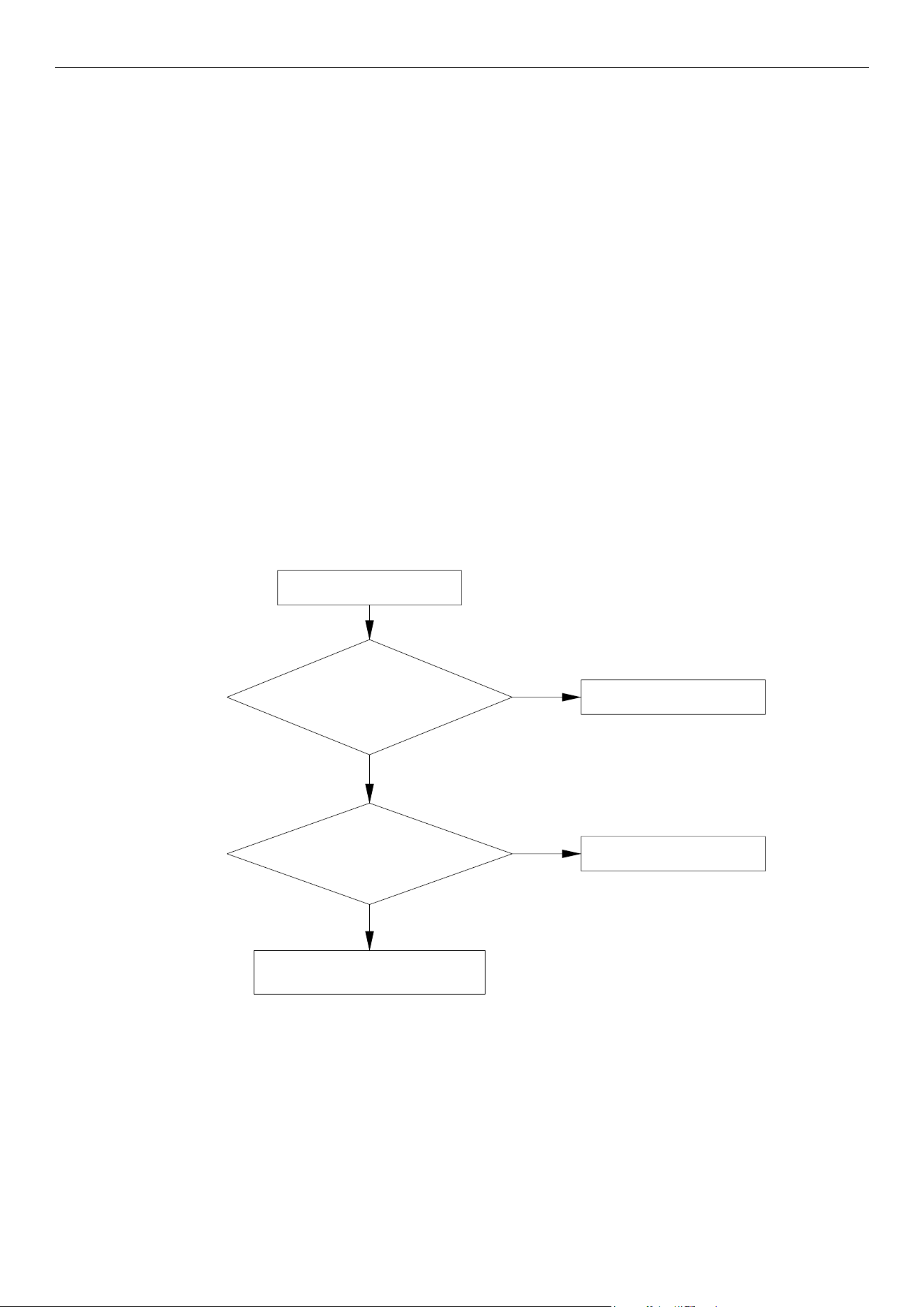
4.4.13 “FM” Water Outlet Temperature Sensor Error
Error display:
Compressor module mainboard LED display screen
Error judgment condition and method:
The resistance value of water outlet temperature sensor is 20 KΩ;
Sample the AD value of temperature sensor through temperature sensor detecting circuit and judge the
range of AD value, If the sampling AD value exceeds upper limit and lower limit in 5 seconds continuously, report
the error.
Possible reason:
■Poor connection between temperature sensor and terminal in mainboard interface
■Temperature sensor is abnormal
■Detecting circuit is abnormal
Troubleshooting
:
WaterWater outletoutlet temperaturetemperature
sensorsensor errorerror
RemoveRemove thethe
temperaturetemperature andand measuremeasure itsits
resistanceresistance value:value: isis itit withinwithin
normalnormal range?range?
ReplaceReplace thethe mainboardmainboard ofof
compressorcompressor modulemodule
ReplaceReplace thethe temperaturetemperature
sensorsensor
YesYes
NoNo
YesYes
NoNo
TheThe temperaturetemperature
sensorsensor isis correctlycorrectly
connectedconnected toto thethe socketsocket onon
mainboard,mainboard, isis it?it?
ConnectConnect thethe temperaturetemperature
sensorsensor corrcetlycorrcetly
MRCOOL® DC INVERTER GEOTHERMAL HEAT PUMP
34
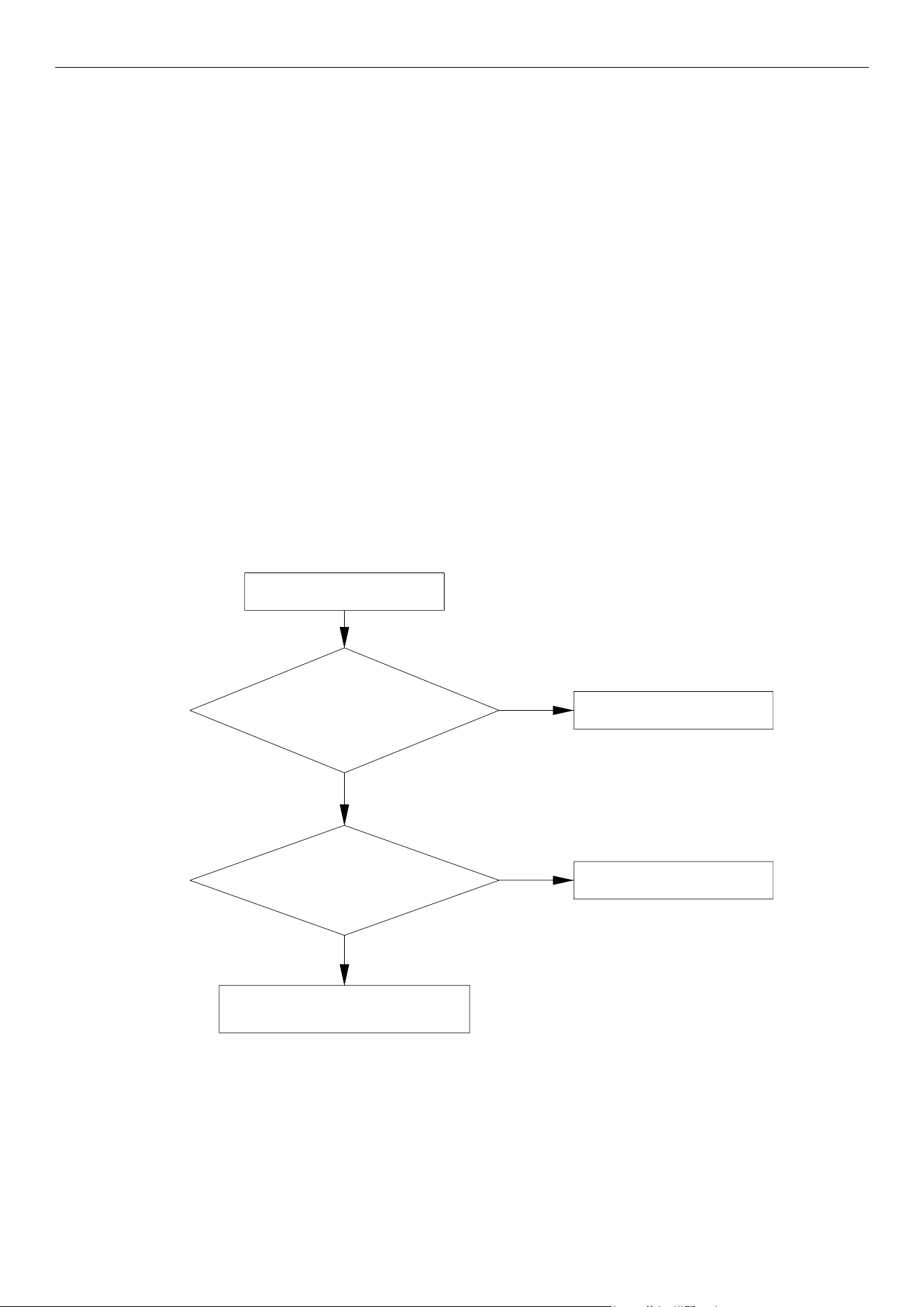
4.4.14 “A7” Liquid Pipe Temperature Sensor Error
Error display:
Compressor module mainboard LED display screen
Error judgment condition and method:
The resistance value of liquid pipe temperature sensor is 20 KΩ;
Sample the AD value of temperature sensor through temperature sensor detecting circuit and judge the
range of AD value, If the sampling AD value exceeds upper limit and lower limit in 5 seconds continuously, report
the error.
Possible reason:
■Poor connection between temperature sensor and terminal in mainboard interface
■Temperature sensor is abnormal
■Detecting circuit is abnormal
Troubleshooting
:
LiquidLiquid pipepipe temperaturetemperature
sensorsensor errorerror
RemoveRemove thethe
temperaturetemperature andand measuremeasure itsits
resistanceresistance value:value: isis itit withinwithin
normalnormal range?range?
ReplaceReplace thethe mainboardmainboard ofof
compressorcompressor modulemodule
ReplaceReplace thethe temperaturetemperature
sensorsensor
YesYes
NoNo
YesYes
NoNo
TheThe temperaturetemperature
sensorsensor isis correctlycorrectly
connectedconnected toto thethe socketsocket onon
mainboard,mainboard, isis it?it?
ConnectConnect thethe temperaturetemperature
sensorsensor corrcetlycorrcetly
MRCOOL® DC INVERTER GEOTHERMAL HEAT PUMP
35
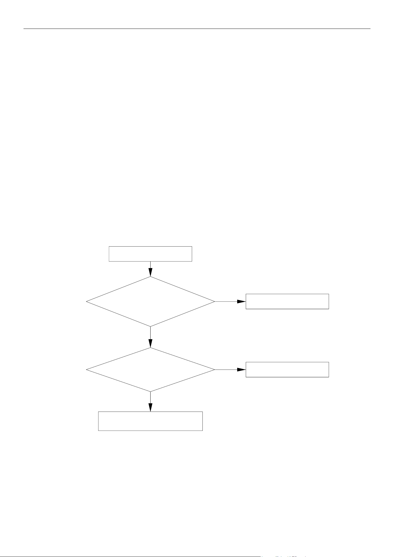
4.4.15 “C2” In-Tube Temperature Sensor Error
Error display:
Compressor module mainboard LED display screen
Error judgment condition and method:
The resistance value of in-tube temperature sensor is 20 KΩ;
Sample the AD value of temperature sensor through temperature sensor detecting circuit and judge the
range of AD value, If the sampling AD value exceeds upper limit and lower limit in 5 seconds continuously, report
the error.
Possible reason:
■Poor connection between temperature sensor and terminal in mainboard interface
■Temperature sensor is abnormal
■Detecting circuit is abnormal
Troubleshooting
:
In-tubeIn-tube temperaturetemperature
sensorsensor errorerror
RemoveRemove thethe
temperaturetemperature andand measuremeasure itsits
resistanceresistance value:value: isis itit withinwithin
normalnormal range?range?
ReplaceReplace thethe mainboardmainboard ofof A-A- CoilCoil
modulemodule
ReplaceReplace thethe temperaturetemperature
sensorsensor
YesYes
NoNo
YesYes
NoNo
TheThe temperaturetemperature
sensorsensor isis correctlycorrectly
connectedconnected toto thethe socketsocket onon
mainboard,mainboard, isis it?it?
ConnectConnect thethe temperaturetemperature
sensorsensor corrcetlycorrcetly
MRCOOL® DC INVERTER GEOTHERMAL HEAT PUMP
36
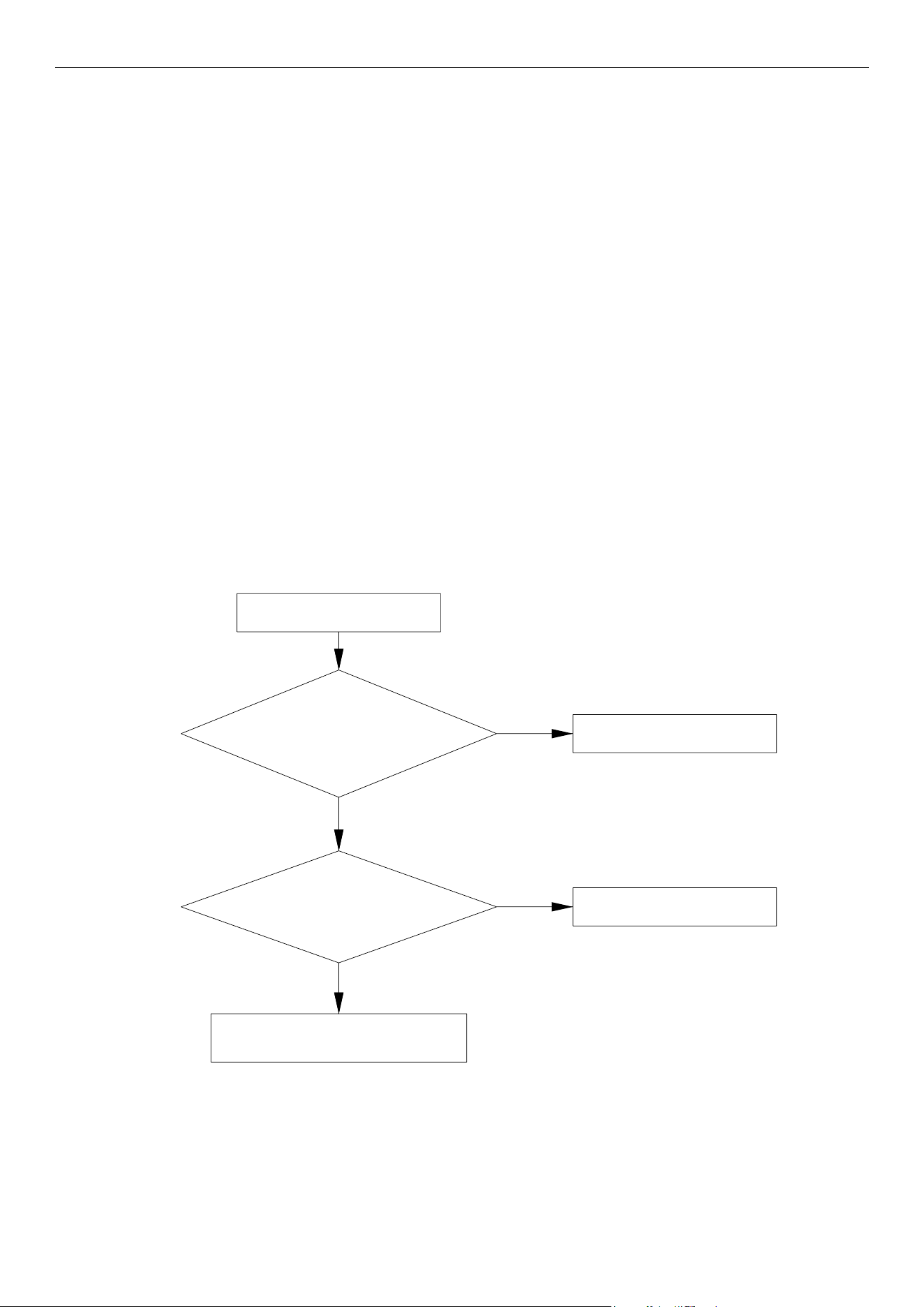
4.4.16 “Cb” Gas Pipe Temperature Sensor Error
Error display:
Compressor module mainboard LED display screen
Error judgment condition and method:
The resistance value of gas pipe temperature sensor is 20 KΩ
Sample the AD value of temperature sensor through temperature sensor detecting circuit and judge the
range of AD value, If the sampling AD value exceeds upper limit and lower limit in 5 seconds continuously, report
the error.
Possible reason:
■Poor connection between temperature sensor and terminal in mainboard interface
■Temperature sensor is abnormal
■Detecting circuit is abnormal
Troubleshooting
:
GasGas pipepipe temperaturetemperature
sensorsensor errorerror
RemoveRemove thethe
temperaturetemperature andand measuremeasure itsits
resistanceresistance value:value: isis itit withinwithin
normalnormal range?range?
ReplaceReplace thethe mainboardmainboard ofof A-A- CoilCoil
modulemodule
ReplaceReplace thethe temperaturetemperature
sensorsensor
YesYes
NoNo
YesYes
NoNo
TheThe temperaturetemperature
sensorsensor isis correctlycorrectly
connectedconnected toto thethe socketsocket onon
mainboard,mainboard, isis it?it?
ConnectConnect thethe temperaturetemperature
sensorsensor corrcetlycorrcetly
MRCOOL® DC INVERTER GEOTHERMAL HEAT PUMP
37
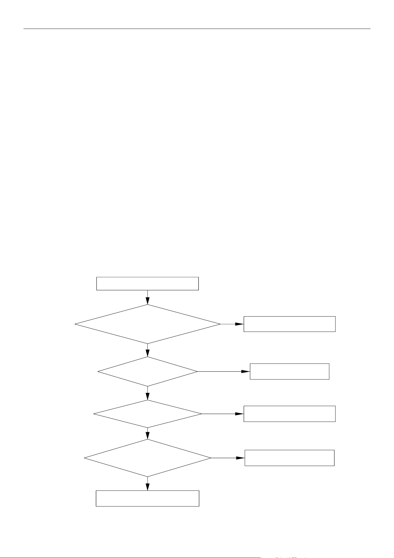
4.4.17 “C1” Return Air Temperature Sensor Error
Error display:
Compressor module mainboard LED display screen
Error judgment condition and method:
The resistance value of return air temperature sensor is15 KΩ
Sample the AD value of temperature sensor through temperature sensor detecting circuit and judge the
range of AD value, If the sampling AD value exceeds upper limit and lower limit in 5 seconds continuously, report
the error.
Possible reason:
■Poor connection between temperature sensor and terminal in mainboard interface
■Temperature sensor is abnormal
■Detecting circuit is abnormal
Troubleshooting
:
ReturnReturn airair temperaturetemperature
sensorsensor errorerror
RemoveRemove thethe
temperaturetemperature andand measuremeasure itsits
resistanceresistance value:value: isis itit withinwithin
normalnormal range?range?
ReplaceReplace thethe mainboardmainboard ofof A-A- CoilCoil
modulemodule
ReplaceReplace thethe temperaturetemperature
sensorsensor
YesYes
NoNo
YesYes
NoNo
TheThe temperaturetemperature
sensorsensor isis correctlycorrectly
connectedconnected toto thethe socketsocket onon
mainboard,mainboard, isis it?it?
ConnectConnect thethe temperaturetemperature
sensorsensor corrcetlycorrcetly
MRCOOL® DC INVERTER GEOTHERMAL HEAT PUMP
38
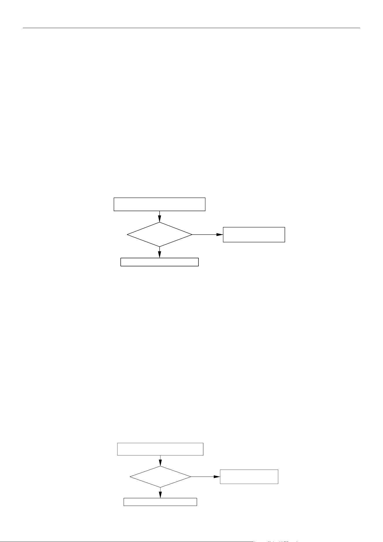
4.4.18 “E6” Communication Error
Error display:
Compressor module mainboard LED display screen
Error judgment condition and method:
The communication between the compressor module and A-Coil module is bad, the display screen of the
compressor module shows the error code, the green light of the A-Coil module mainboard will light for 1 second
then flash 6 times. The unit will automatically restart after the communication has recovered for 30 seconds
continuously.
Possible reason:
■Poor connection of compressor module mainboard terminal
■Poor connection of A-Coil module mainboard terminal
■The power of A-Coil module or compressor module is cut off
■Detecting circuit is abnormal
■Interference of other equipment
Troubleshooting
:
CommunicationCommunication errorerror
MeasureMeasure
thethe communicationcommunication line:line: isis itit
through?through?
CheckCheck
thethe communicationcommunication lineline
betweenbetween CompressorCompressor modulemodule andand A-CoilA-Coil
module:module: isis itit properlyproperly
connected?connected?
CheckCheck thethe
powerpower ofof thethe unit:unit: isis itit
turnturn on?on?
ReplaceReplace thethe transimissiontransimission
lineline
TurnTurn onon thethe powerpower
YesYes
IsIs therethere
anyany equipmentequipment whichwhich cancan
emitemit electromagneticelectromagnetic waveswaves nearnear
thethe unit?unit?
RemoveRemove thethe equipmentsequipments 1
metermeter awayaway fromfrom thethe unitunit
ReplaceReplace thethe mainboardmainboard ofof unitunit
YesYes
YesYes
YesYes
NoNo
NoNo
NoNo
NoNo
YesYes
ConnectConnect thethe communicationcommunication
lineline corrcetlycorrcetly
MRCOOL® DC INVERTER GEOTHERMAL HEAT PUMP
39
4.4.19 “PL” DC Bus Under-Voltage Protection or DC Bus Voltage Drop Error
Error display:
Compressor module mainboard LED display screen
Error judgment condition and method:
When compressor is running and there is no other error, if busbar voltage is lower than the set value for low
voltage protection, the DC Bus Under-Voltage Protection or DC Bus Voltage Drop Error is reported. The display
screen of the main board displays the error code, and the unit shuts down.
Possible reason:
■Voltage is abnormal.
■Busbar voltage sampling circuit element is damaged or busbar voltage sampling AD terminal is abnormal.
Troubleshooting
:
DCDC BusBus Under-VoltageUnder-Voltage ProtectionProtection oror
DCDC BusBus VoltageVoltage DropDrop ErrorError
IsIs voltagevoltage
belowbelow thethe normalnormal
value?value?
ReplaceReplace thethe mainboardmainboard
NormalNormal protectionprotection
NoNo
YesYes
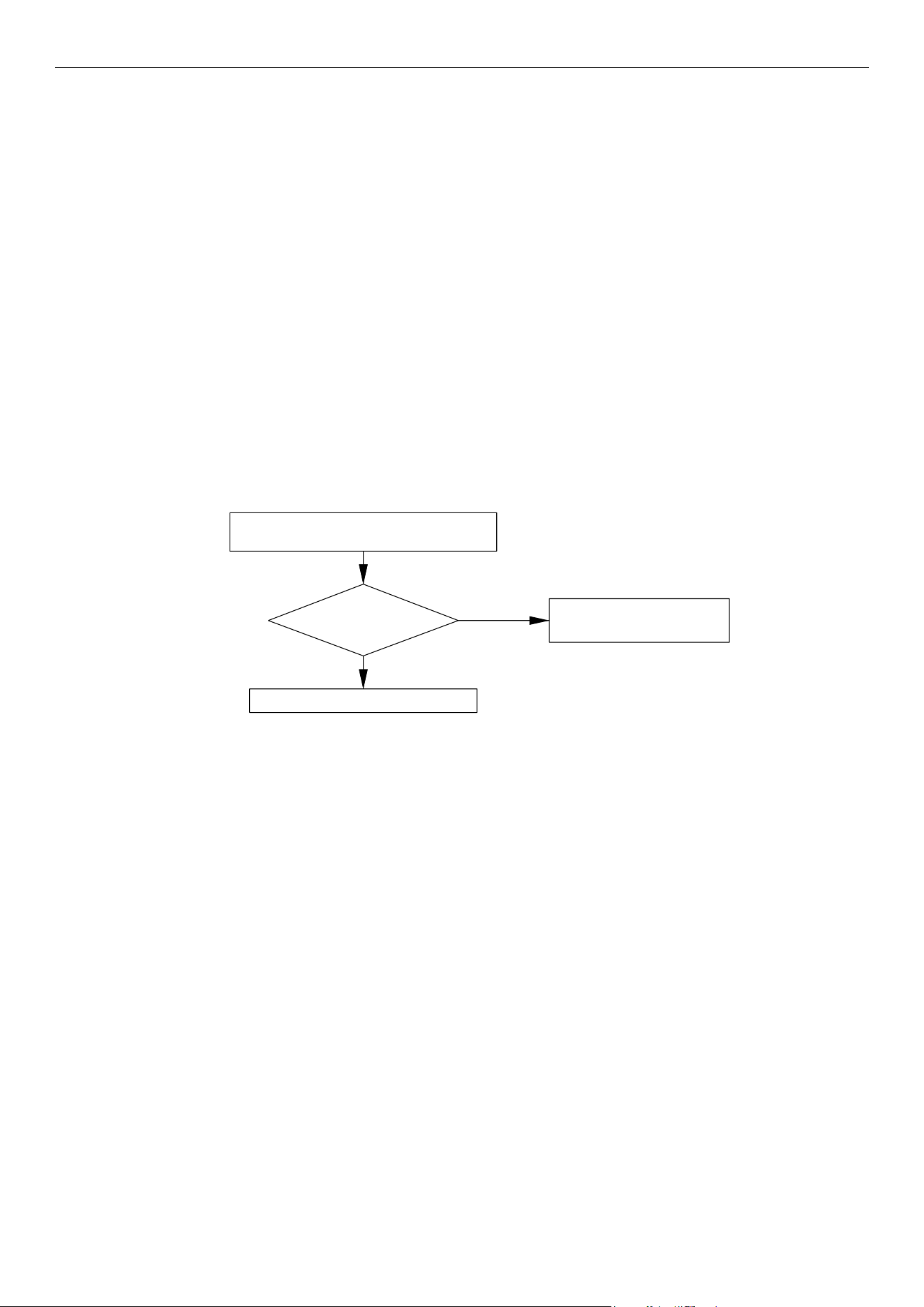
4.4.20 “PH” DC Bus Over-Voltage Protection
Error display:
Compressor module mainboard LED display screen
Error judgment condition and method:
If there is no other malfunction and the busbar voltage is higher than the set value for high voltage protection,
then it can be judged that DC bus over-voltage protection occurs, the display screen of the compressor module
shows the error code. System will shut down for protection.
Possible reason:
■Voltage is abnormal.
■Busbar voltage sampling circuit element is damaged or busbar voltage sampling AD terminal is abnormal.
Troubleshooting
:
DCDC BusBus Over-VoltageOver-Voltage ProtectionProtection
ReplaceReplace thethe mainboardmainboard
NormalNormal protectionprotection
IsIs thethe
voltagevoltage higherhigher thanthan
normalnormal value?value?
NoNo
YesYes
MRCOOL® DC INVERTER GEOTHERMAL HEAT PUMP
40
4.4.21 “PU” Charging Circuit Error
Error display:
Compressor module mainboard display screen
Error judgment condition and method:
When the charge loop starts to get charged and the busbar voltage cannot reach the set value in a certain
period of time, the charging circuit error is reported, the display screen of the compressor module shows the error
code. System will shut down for protection.
Possible reason:
■Voltage is too low.
■Charge loop element is abnormal.
■Busbar voltage sampling circuit element is damaged or Busbar voltage sampling AD terminal is abnormal.
Troubleshooting
:
ChargingCharging CircuitCircuit ErrorError
IsIs voltagevoltage
belowbelow thethe normalnormal
value?value?
ReplaceReplace thethe mainboardmainboard
NormalNormal protectionprotection
NoNo
YesYes
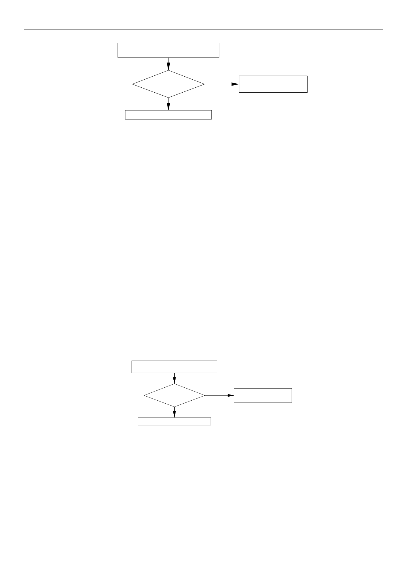
4.4.22 “LF” Power Protection
Error display:
Compressor module mainboard LED display screen
Error judgment condition and method:
When the power of the unit is detected to be higher than normal for a continuous period of time, the system
will enter Power Protection. The unit shuts down. The display screen of the compressor module shows the error
code. After the compressor is shut down for a period of time, if the power is detected less than the limit value, the
error is cleared, and the unit will return to normal and restart. If Power Protection occurs multiple times within a
certain period of time, the error cannot be automatically cleared and can only be cleared through manual power
off.
Possible reason:
■Power is too high
■Detecting circuit is abnormal.
Troubleshooting
:
MRCOOL® DC INVERTER GEOTHERMAL HEAT PUMP
41
PowerPower ProtectionProtection
ReplaceReplace thethe mainboardmainboard
NormalNormal protectionprotection
IsIs thethe
powerpower higherhigher thanthan
normalnormal value?value?
NoNo
YesYes
4.4.23 “E5” Current Protection
Error display:
Compressor module mainboard LED display screen
Error judgment condition and method:
When the power of the unit is detected to be higher than normal for a continuous period of time, the system
will enter Current Protection. The unit shuts down. The display screen of the compressor module shows the error
code. After the compressor is shut down for a period of time, if the current is detected less than the limit value, the
error is cleared, and the unit will return to normal and restart. If Current Protection occurs multiple times within a
certain period of time, the error cannot be automatically cleared and can only be cleared through manual power
off.
Possible reason:
■The unit current is too high
■Detecting circuit is abnormal.
Troubleshooting
:
CurrentCurrent ProtectionProtection
ReplaceReplace thethe mainboardmainboard
NormalNormal protectionprotection
IsIs thethe
currentcurrent higherhigher thanthan
normalnormal value?value?
NoNo
YesYes
4.4.24 “E0” Fan Error
Error display:
Compressor module mainboard LED displayer
Error judgment condition and method:
If the fan error is detected for a continuous period of time, the display screen of the compressor module
shows the error code, the green light of the A-Coil module mainboard will light for 1 second then flash 2 times. If
the detection returns to normal for a continuous period of time, the unit will return to normal operation. If the
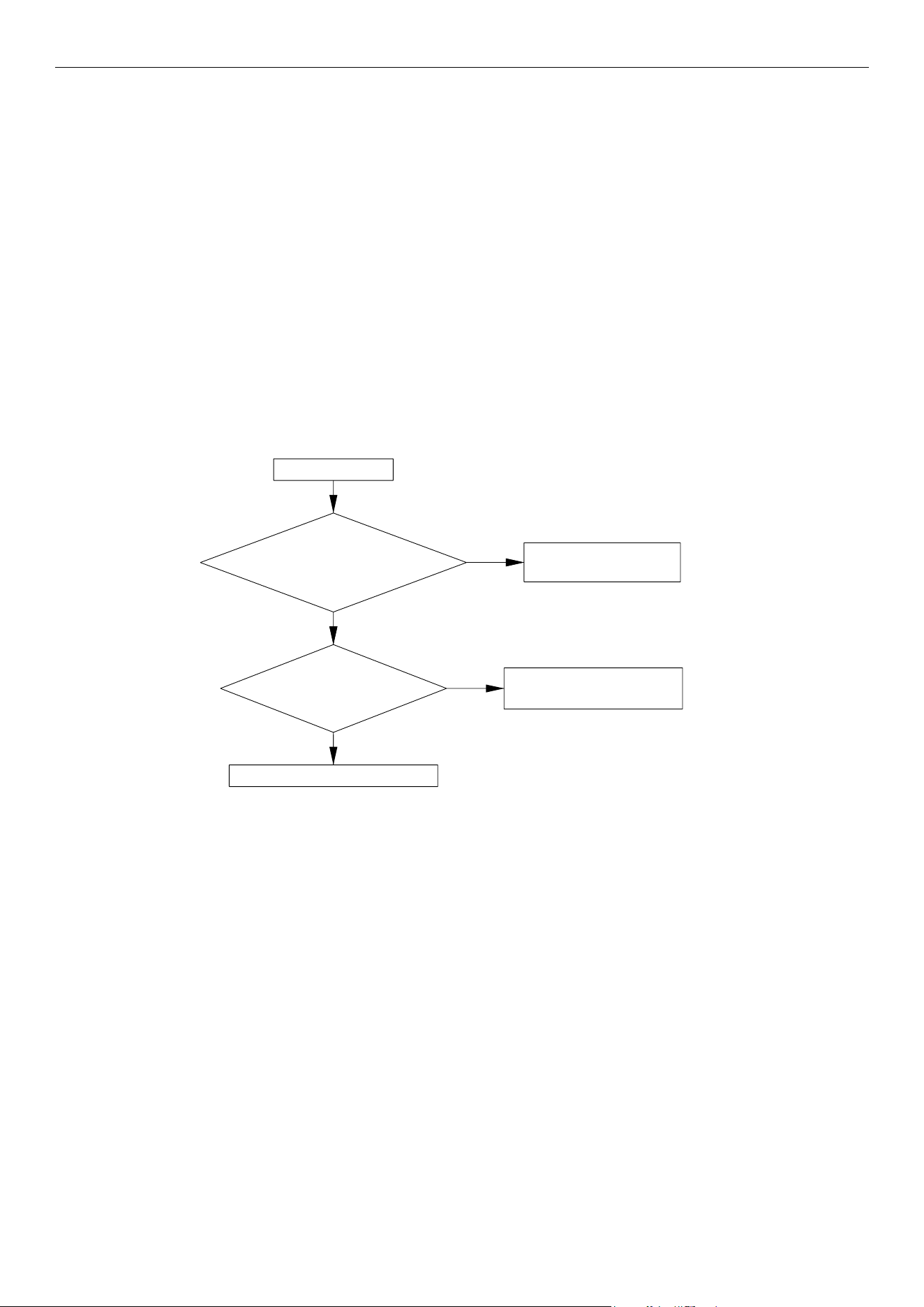
MRCOOL® DC INVERTER GEOTHERMAL HEAT PUMP
42
continuous trigger protection exceeds a certain number of times, the error cannot be automatically cleared, the
need to manually power off to clear the fault.
If the unit receives fan signal from the thermostat, but the fan does not operate, it is determined that the fan
signal wiring between thermostat and the unit is abnormal, and the fan error is reported, the error cannot be
automatically cleared, and can only be manually powered off to clear the error.
Possible reason:
■Fan error
■Detecting circuit is abnormal
■The fan signal wiring between thermostat and the unit is abnormal
Troubleshooting
:
FanFan ErrorError
CheckCheck thethe fanfan signalsignal
wiringwiring betweenbetween thethe thermostatthermostat
andand thethe unitunit : isis itit properlyproperly
connected?connected?
ReplaceReplace thethe
fanfan ofof thethe BlowerBlower module,module,
errorerror stillstill exitsexits ?
ReplaceReplace thethe mainboardmainboard
AdjustAdjust thethe wiringwiring
UseUse thethe newnew fan,Thefan,The lastlast
oneone isis damageddamaged
YesYes
NoNo
YesYes
NoNo
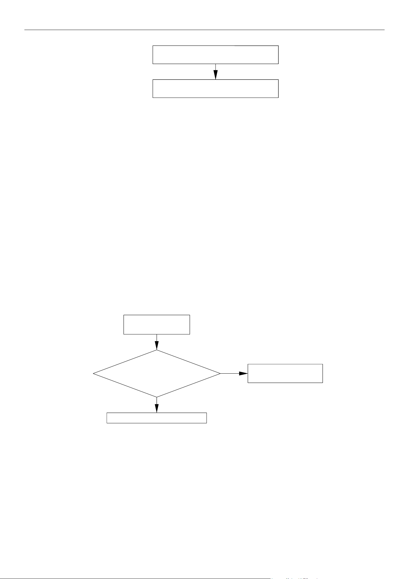
4.4.25 “C9” Chip Error
Error display:
Compressor module mainboard LED display screen
Error judgment condition and method:
If unit detect chip self-test abnormally, the display screen of the compressor module shows the error code,
the error cannot be automatically cleared, and can only be manually powered off to clear the error.
Possible reason:
■Chip self-test abnormally
Troubleshooting:
Replace the mainboard of Compressor module.
MRCOOL® DC INVERTER GEOTHERMAL HEAT PUMP
43
ChipChip ErrorError
ReplaceReplace thethe mainboardmainboard ofof
CompressorCompressor modulemodule
4.4.26 “LP” Capacity DIP Switch Setting Error
Error display:
Compressor module mainboard LED display screen
Error judgment condition and method:
If the capacity of the compressor module and the A-Coil module is not consistent for a period of time, the
compressor module mainboard display screen shows the error code, the green light of the A-Coil module
mainboard will light for 1 second then flash 1 times and the unit shuts down. The error need to be cleared by
manually powering off the unit.
Possible reason:
■Compressor module and A-Coil module capacity dip switch setting error
■Detecting circuit is abnormal
Troubleshooting:
CapacityCapacity DIPDIP SwitchSwitch
SettingSetting ErrorError
CheckCheck thethe
capacitycapacity dipdip switchesswitches
ofof CompressorCompressor modulemodule andand A-CoilA-Coil
module:module: isis itit properlyproperly
setted?setted?
ReplaceReplace thethe mainboardmainboard
AdjustAdjust thethe capacitycapacity dipdip
switchesswitches
NoNo
YesYes
MRCOOL® DC INVERTER GEOTHERMAL HEAT PUMP
44
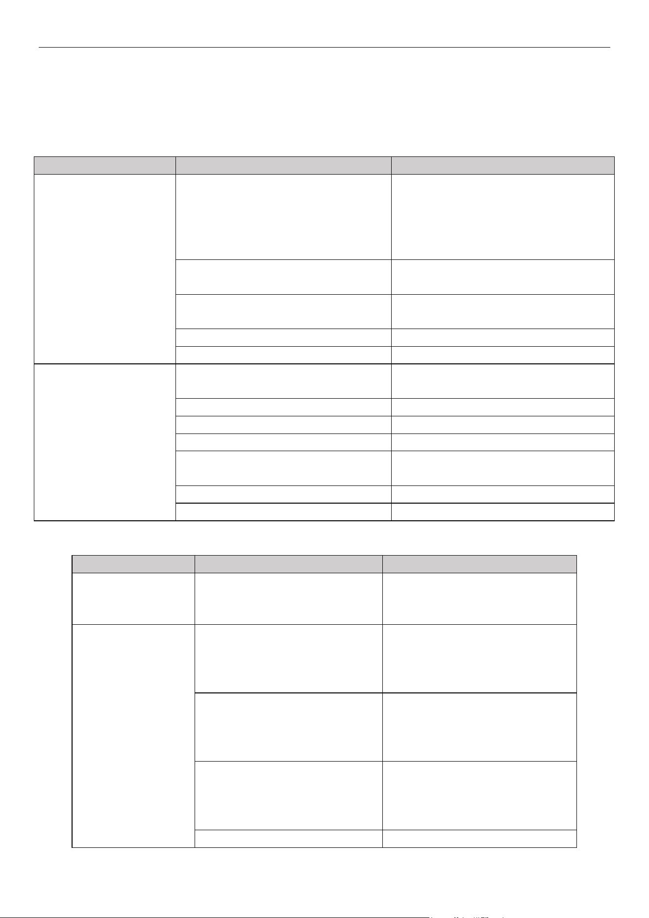
4.5 Failures Not Caused by Errors
(1) If your geothermal unit fails to function normally, please first check the following items before
maintenance:
Problem
Cause
Corrective measure
The geothermal unit
can't run.
If you turn off the unit and then
immediately turn it on, in order to
protect the compressor and avoid
system overload, compressor will
delay running for 3min.
Please wait for a while.
Wire connection is wrong.
Connect wires according to the wiring
diagram.
Fuse or circuit breaker is broken.
Replace the fuse or switch on the circuit
breaker.
Power failure.
Restart after power is resumed.
Power plug is loose.
Re-insert the power plug.
Bad cooling or heating
effect.
Air inlet and outlet of the units have
been blocked.
Clear the obstacles and keep the room
for the units well ventilated.
Improper temperature setting
Reset a proper temperature.
Fan speed is too low.
Reset a proper fan speed.
Doors or windows are open.
Close them.
Exposed under direct sunshine.
Put on curtains or louvers in front of the
windows.
Too many heat sources in the room.
Remove unnecessary heat sources.
Filter is blocked or dirty.
Clean or change the filter.
The following situations are not operation failures.
Problem
Time of occurrence
Cause
Mist comes from the
geothermal unit.
During operation.
If the unit is running under high
humidity, the wet air in the room
will be quickly cooled down.
The geothermal unit
generates some
noise.
When the unit is turned on, it
purrs.
When the system is just started,
the refrigerant is not stable. About
30s later, the purr of the unit
becomes low.
About 40s after the unit first
enables the heating mode
It’s the sound of 4-way valve
switching direction. The sound will
disappear after the valve changes
its direction.
There is hissing sound when the
unit is started or stopped and a
slight hissing sound during and
after operation.
It's the sound of gaseous
refrigerant that stops flowing and
the sound of drainage system.
There is a sound of crunching
Because of temperature change,

MRCOOL® DC INVERTER GEOTHERMAL HEAT PUMP
45
Problem
Time of occurrence
Cause
during and after operation.
front panel and other components
may be swelled up and cause
abrasion sound.
There is a hissing sound when
the unit is turned on or suddenly
stopped during operation.
Because refrigerant suddenly
stops flowing or changes the flow
direction.
Dust comes from the
geothermal unit.
The unit starts operation after
being unused for a long time.
Dust inside the units come out
together with the air.
The geothermal unit
generates some
smell.
During operation.
The room smell or the smell of
cigarette comes out through the
units.
NOTICE:
Check the above items and adopt the corresponding corrective measures. If the
geothermal unit
continues
to function poorly, please stop the geothermal unit immediately and contact MRCOOL®'s authorized local
service center. Ask our professional service staff to check and repair the unit.

MRCOOL® DC INVERTER GEOTHERMAL HEAT PUMP
46
5 Maintenance
5.1 System Diagram
5.2 Connection Pipe Vacuum Pumping
NOTICE
①
Make sure the outlet of vacuum pump is away from fire source and is well-ventilated.
②
Before vacuum pumping, make sure the unit cut-off valves are closed.
③
When vacuum pumping, both the liquid pipe and the gas pipe must be pumped.
(1) Remove the caps of the liquid pipe cut-off valve, gas pipe cut-off valve and also the service port.
(2) Meanwhile the gas and liquid pipe cut-off valves should be kept closed in case of refrigerant leak.
(3) Connect the hose used for evacuation to the vacuum pump.
(4) Open the switch at the lower pressure side of the manifold valve assembly and start the vacuum pump.
Meanwhile, the switch at the high pressure side of the manifold valve assembly should be kept closed,
otherwise evacuation would fail.
(5) The evacuation duration depends on the unit’s capacity, generally.
Model
Time(min)
GCSHPM060IN
GCSCAM060GN
35
GCSHPM048IN
GCSCAM048GN
35
And verify if the pressure gauge at the low pressure side of the manifold valve assembly reads -0.1Mpa

MRCOOL® DC INVERTER GEOTHERMAL HEAT PUMP
47
(-750mmHg), if not, it indicates there is leak somewhere. Then, close the switch fully and then stop the vacuum
pump.
(6) Wait for 10min to see if the system pressure can remain unchanged. If the pressure increase, there may be
leakage.
(7) Slightly open the liquid pipe cut-off valve and let some refrigerant go to the connection pipe to balance the
pressure inside and outside of the connection pipe, so that air will not come into the connection pipe when
removing the hose. Notice that the gas and liquid pipe cut-off valve can be opened fully only after the
manifold valve assembly is removed.
(8) Place back the caps of the liquid pipe cut-off valve, gas pipe cut-off valve and also the service port.
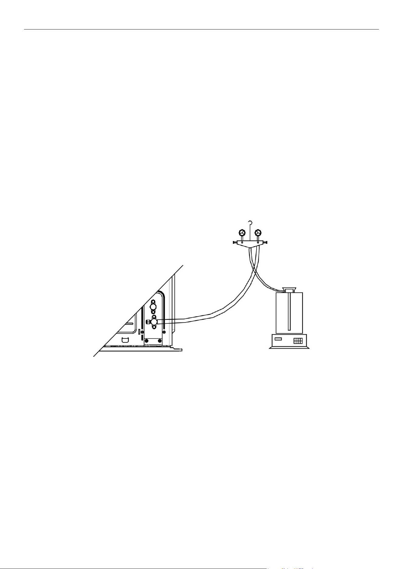
MRCOOL® DC INVERTER GEOTHERMAL HEAT PUMP
48
5.3 Refrigerant Charging
Pre-charging
Step 1: Connect the high pressure gauge line to the valve of liquid pipe and connect the low pressure gauge
line to the valve of gas pipe. Connect the middle gauge line to the vacuum pump. Power on the vacuum pump
and perform vacuum drying.
Step 2: After vacuum drying, close the high and low pressure gauge valves. Then remove the middle gauge
line from the connector of vacuum pump. Then connect to the refrigerant tank.
Step 3: Loosen the middle gauge line from the connector of pressure gauge to a proper extent and slightly
open the valve of refrigerant tank. Evacuate the middle gauge line. Then tighten up the connector again and
completely open the valve of refrigerant tank at the same time.
Step 4: Keep the refrigerant tank erect and put it on an electronic scale. Record the current weight as m1.
Step 5: Open the high pressure gauge valve (Keep the low pressure gauge valve closed). Then charge
refrigerant into the system. Meanwhile, record the weight of refrigerant tank as m2.
Step 6: m1-m2=m. If m equals to the required charging quantity M, close the valve of refrigerant tank at once.
Then move to step 8.
Step 7: If you can’t continue to charge refrigerant into the system and the quantity of charged refrigerant is
less than the required charging quantity, then record the current quantity of charged refrigerant:
m=m1-m2
m`=M-m
The remaining charging quantity is: m`=M-m
Step 8: After charging, remove the pressure gauge.

MRCOOL® DC INVERTER GEOTHERMAL HEAT PUMP
49
Refrigerant charging when unit is turned on:
Step 1: Close the valve of refrigerant tank. First remove the pressure gauge lines and connect the
compressor module and the A-Coil module. Then reconnect the pressure gauge lines. Connect the low pressure
gauge line to the other joint of gas pipe cut-off valve and connect the high pressure gauge line to the liquid pipe
cut-off valve. Connect the middle gauge line to the vacuum pump. Power on the vacuum pump and perform
vacuum drying.
Step 2: After vacuum drying, close the high and low pressure gauge valves. Then remove the middle gauge
line from the connector of vacuum pump. Then connect to the refrigerant tank.
Step 3: Loosen the middle gauge line from the connector of pressure gauge to a proper extent and slightly
open the valve of refrigerant tank. Evacuate the middle gauge line. Then tighten up the connector again and
completely open the valve of refrigerant tank at the same time.
Step 4: Turn on the units and let it run for a while.
Step 5: Open the low pressure gauge valve (Keep the high pressure gauge valve closed). Then charge in the
remaining charging quantity m`.
Step 6: After all required refrigerant is charged in, close the valve of refrigerant tank.
Step 7: Remove the pressure gauge to finish the refrigerant charging work.
Procedure of refrigerant charging
Following is the supplementary requirement for refrigerant charging on the basis of normal procedure:
1) Make sure that when charging refrigerant into the system, no other types of refrigerant will be mixed.
The pipeline for refrigerant charging should be as short as possible to reduce the amount of refrigerant
left in it.
2) The refrigerant tank should stand erect.
3) Make sure the refrigerating system is already grounded before refrigerant charging.
4) When charging is completed (or not yet completed), stick a label on the system.
5) Before re-charging refrigerant into the system, use oxygen-free nitrogen to perform pressure test. When
charging is completed, perform leak test before trial running. Before leaving the workplace, perform a
leak test again.

MRCOOL® DC INVERTER GEOTHERMAL HEAT PUMP
50
5.4 Maintenance of Major Components
5.4.1 How to replace the compressor
5.4.1.1 Diagnosis of compressor failure
A. On condition that the unit can be started up
Step 1:
If the unit can be started up, then start it up to check the current of the faulted compressor. Use a pressure
gauge to measure the pressure of the big and small valves. Connect with a computer to monitor the data. Refer
to the following table based on the recommended working current. The electric current of an inverter compressor
will be different under different rotation speed or different working conditions. If the compressor is working at
60Hz, the working current corresponding to different condensing temperature and evaporating temperature is
shown below:
Inverter compressor
Step 2:
Judge whether the operating noise of the compressor is normal, and whether there is a sharp noise or
obvious scraping. If there is a normal compressor working nearby, compare their operating noise.
Step 3:
Examine whether the electronic expansion valve of the unit is active and whether the 4-way valve works or
not. How to examine:
(1) Electronic expansion valve:
The electronic expansion valve will be reset every time when the unit is powered on or off. Touch the valve
and you can feel the movement of the valve spool. In the last stage of the reset process, you will hear the click of
the valve and feel its vibration.
MRCOOL® DC INVERTER GEOTHERMAL HEAT PUMP
51
Touch the electronic expansion valve:
a. Touch the top of the electronic expansion valve and you can feel their move as they are reset upon
startup.
b. Make sure the coil is fixed firmly.
(2) 4-way valve:
During normal operation, the 4 copper tubes that connect to the valve will have different temperature. When
the 4-way valve is working, it will generate some noise and vibration.
This is the position of the 4-way
valve. Do not touch it directly with
your hands. There is hot refrigerant
at the discharge pipe, so be careful
not to be scalded.
Electronic expansion
valve

MRCOOL® DC INVERTER GEOTHERMAL HEAT PUMP
52
D- Connect to the discharge side
Caution! High temperature!
Labels on the 4-way valve:
D-connect to the discharge side; E-connect to the evaporator of A-Coil module;
S-connect to the inhalation side of the liquid separator; C-connect to the condenser;
When the system is in cooling mode, C-the pipeline is with high pressure and high temperature; E, S-the
pipeline is with low pressure and low temperature;
When the system is in heating mode, E-the pipeline is with high pressure and high temperature; C, S-the
pipeline is with low pressure and low temperature;
Because D is connected to the discharge side, it is with high pressure and high temperature regardless of
the operating mode. When the unit is powered on, in oil return mode, the 4-way valve will produce some noise.
Do not touch the pipes directly with your hands and be cautious of the hot temperature.
Step 4:
Check the drive board of compressor, i.e. the IPM module.
Please refer to the IPM checking method in the section of troubleshooting.
Check the drive board of compressor, i.e. the IPM module.
Please refer to the IPM checking method in the section of troubleshooting.
B
.
On condition that the unit cannot be started up
Step 1:
Cut off the power supply and detach the cover of the wiring box of the compressor. Check the wiring of the
compressor.
Step 2:
Check the resistance between the wiring terminals (U, V, W) of compressor.
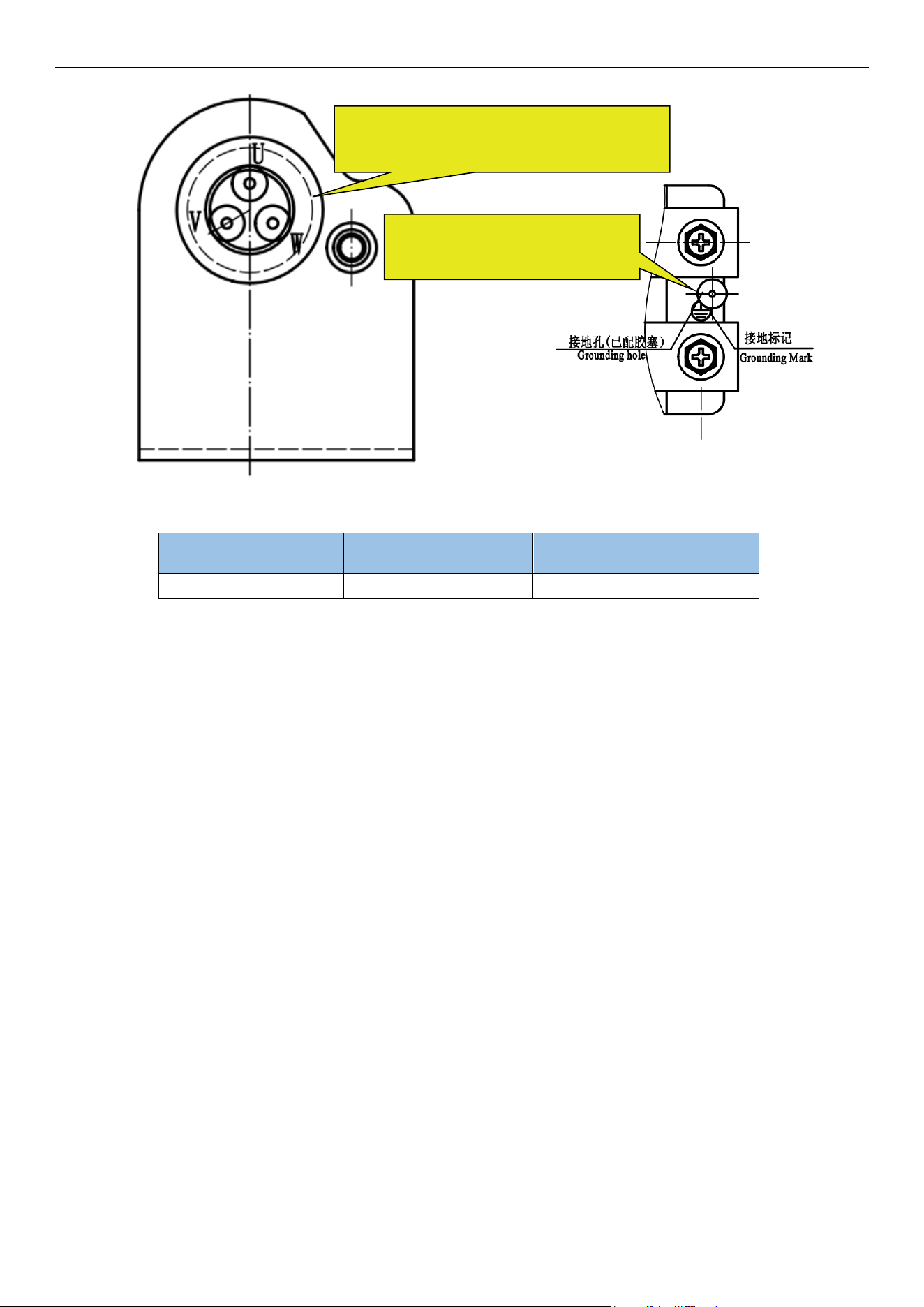
MRCOOL® DC INVERTER GEOTHERMAL HEAT PUMP
53
Refer to the following table for the resistance between any two terminals:
UV Winding resistance VW Winding resistance WU Winding resistance
0.67
±
5%
Ω
0.67
±
5%
Ω
0.67
±
5%
Ω
Measure the earth resistance of each wiring terminal. The resistance should be above 10 megohm. If not, we
can judge that the compressor is faulted inside.
Step 3:
On condition that the unit cannot be started up, we also need to check the solenoid valve assembly of the
system, including the electronic expansion valve. The checking method is the same as instructed above.
Step 4:
Check whether the IPM module is normal. Please refer to the IPM checking method in the section of
troubleshooting.
5.4.1.2 Replacement of compressor
Step 1: Preparation
(1) Prepare the components for replacement
When carrying the old and new compressors, do not place the compressors horizontally or upside down. The
angle of inclination should be within ±30°. Make sure the lubricant inside the compressors will not flow from the oil
balance mouth. The suction and discharge openings of the compressors must be sealed. If a rubber seal is
missing, user adhesive tape to seal the opening. This is to prevent the compressor oil from contacting the air.
Measure the earth resistance of
the three terminals respectively.
Use a universal KWh meter to measure the
resistance between two terminals.

MRCOOL® DC INVERTER GEOTHERMAL HEAT PUMP
54
Make sure the rubber seals of
the suction and discharge
openings of the compressor are
in good condition.
Make sure the electric box cover of the
compressor is in good condition.

MRCOOL® DC INVERTER GEOTHERMAL HEAT PUMP
55
NOTICE:
Make sure the lubricant is sealed inside the compressors.
(2) Prepare relevant tools
1) Prepare nitrogen. Please strictly follow the nitrogen welding standards during the welding process.
Make sure there is sufficient nitrogen. The nitrogen pressure should be above 2.0MPa;
2) Prepare welding rods. Prepare some welding rods of common specifications and some special
welding rods that contain more than 5% silver. They are used to weld the compressor. The suction
and discharge openings of the compressor are all connected to copper-plated steel pipes, so we
need to use special welding rods and solder;
3) Prepare applicable welding tools. Please evaluate how much oxygen and acetylene should be used
according to the current welding condition. Try to avoid repeated welding.
4) Prepare a complete set of tools, including an internal hexagonal wrench, diagonal pliers, pincer
pliers, nipper pliers, a universal meter, a pressure gauge, cross screwdriver, straight screwdriver,
more than two wrenches, insulating tape and wire cables.
Step 2: Disconnect power
If the compressor needs to be replaced after judging as above, then switch off the compressor module and
disconnect the power cable of the compressor module. Use insulating tape to wrap the power cable and put a
notice board on the power switch to remind people to be cautious of electric shock.
Step 3: Neaten the electric components
When you detach the compressor wires and temperature sensors, mark them correspondingly for the
convenience of reconnecting them.
Step 4: Discharge refrigerant
Discharge refrigerant from the system. Discharge simultaneously from the high pressure side and low
pressure side. Do not discharge too fast (It should take more than 12h to completely discharge the refrigerant);
otherwise, large quantity of lubricant will escape from the system together with the refrigerant.
Step 5: Detach the compressor
Check the condition of the damaged compressor, including its position and model.
If the information of the compressor is confirmed, check the oil quality.
(a) If the oil is clear and impurities-free, we consider that the oil of the system is not polluted. Meanwhile, if
we confirm that the valves and pipes are also normal, then we can replace the compressor only. For the removal
of compressor, please refer to the section: Removal of Major Components.
How to check oil quality?

MRCOOL® DC INVERTER GEOTHERMAL HEAT PUMP
56
(1) After the compressor is detached, put it on a solid ground and shake it at an angle of 30~45° to ensure
that the contaminant at the bottom of the compressor can be poured out.
(2) Place the compressor at a position above the ground level and then pour out the oil from the air outlet of
the compressor. Collect the oil in a transparent container. The amount of oil should be over 150ml.
NOTE:
1) The axial direction of the compressor should not slant at an angle larger than 20° to the horizontal
direction.
2) Prevent the compressor from falling.
3) Put a transparent container (over 150ml in volume) under the discharge pipe to collect the
compressor oil, thus we can see the oil quality.
(3) Put the container of compressor lubricant in a bright location and see if there is impurity and
discoloration. Sniff at the compressor lubricant. Normally, there is no pungent smell.
(b) If the oil is contaminated, replace the compressor and the gas-liquid separator.
NOTE:
Confirm whether the compressor needs to be replaced. The pipe mouths of the faulted compressor must
be sealed by adhesive tape as soon as the compressor is detached. Make sure the compressor is well preserved
for the ease of future analysis.
Step 6: Clear the pipeline
After confirming which parts of the system should be replaced, check the pipeline of the system. Blow
through the main pipeline with nitrogen. After clearing the pipeline, if the components are not replaced
immediately, seal the pipeline with adhesive tape to prevent the system from being contaminated by water and
impurities in the air.
Step 7: Replace the compressor
For the removal of compressor, please refer to the section: Removal of Major Components.
Step 8: Check the system for leaks
(1) First of all, check each welding point. Check whether the welding points are smooth and whether there is
any obvious welding hole or other abnormal condition.
(2) Next, fill high-pressure nitrogen into the system for leak detection. If it is only the compressor module
that needs to be repaired and the A-Coil module is confirmed normal, then it’s OK to charge
high-pressure nitrogen into the compressor module only. Fill in the nitrogen simultaneously from the high
pressure side and low pressure side. We recommend charging the nitrogen from the big and small
valves at the same time. The pressure of nitrogen should be above 20kgf. Then use soapy water to

MRCOOL® DC INVERTER GEOTHERMAL HEAT PUMP
57
check for leaks. Check the welding points particularly.
(3) Finally, retain the pressure of the system. Fill high-pressure nitrogen into the system and maintain the
pressure above 25kgf. Close the big and small valves and keep the pressure of A-Coil module and
compressor module for more than 12h. If the pressure remains unchanged, then start vacuum pumping;
otherwise, check the system for leaks again.
Temperature should be considered when judging the pressure change. If temperature changes by 33.8°F
(1℃), pressure will change by 0.01MPa or so.
For example, if temperature is 86°F (30℃) when nitrogen of 2.5MPa is charged, and temperature changes
to 77°F (25℃) after 12h, we consider that the system is qualified if the pressure is found at 2.43MPa or above.
Step 9: Evacuate the system and charge refrigerant
Please refer to the section of maintenance: vacuum pumping and refrigerant charging.
Step 10: Connect electric components
Connect cables, compressor wires and the electric heating belt according to the signs marked before and
the wiring diagram on the cover of the electric box.
5.4.2 How to replace the drive module of compressor
Step 1: First, make sure that power is cut off. Set the universal meter at the AC voltage and measure the
voltage between AC-L and N. If each time the voltage is 0V (Errors may occur to the universal meter, sometimes
the voltage may not be 0V), proceed with the next step and put a sign on the power switch that reads “Under
maintenance, don’t switch on”.
Step 2: Measure the voltage between DC bus P and UN on the drive board of the compressor. Set the
universal meter at the DC voltage and measure the voltage between P and UN as shown below. If the voltage is
below 36V, proceed with the next step. In case that a universal meter is not available, disconnect power for 20min
and then continue with the next step.
Step 3: Remove all the wires on the drive board of the compressor with insulation glove.
Step 4: Remove the screws on the drive board of the compressor. The screws are located in the white circles
as shown above in the picture.
Step 5: Replace with a new compressor drive board. Before replacement, apply some silica gel on the IPM
module
、
rectifier
,
MOSFET and diode.
Step 6: Install the new compressor drive board. Fix the screws and connect the wires correctly.

MRCOOL® DC INVERTER GEOTHERMAL HEAT PUMP
58
5.5 Removal of Major Components
5.5.1 Major Components of Compressor Module
Picture
Name
Function
Compressor
Through compression, the low pressure refrigerant occupies a less space.
As its pressure and temperature both rise, it becomes high pressure and
high temperature refrigerant. It is the power drive of the system.
4-Way Valve
Usually used in heat pump systems to switch the flow direction of
refrigerant in the system, in order to achieve the conversion of unit cooling
and heating
Fan
Introduce external air into the unit and cool the heating module on the main
board through a heat sink to ensure normal operation of the main board.
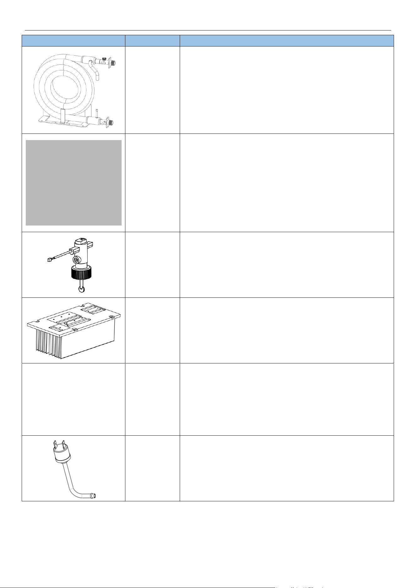
MRCOOL® DC INVERTER GEOTHERMAL HEAT PUMP
59
Picture
Name
Function
Condenser
It is used to transfer partial heat of the hot flow to the cold flow so that the
flow temperature can reach the specified index. It is an energy exchanging
device.
Electronic
Expansion Valve
The unit is equipped with two electronic expansion valves, located in the
Compressor module and the A-Coil module, respectively, for the control of
heating mode and cooling mode. The function of the electronic expansion
valve is as follows:
1. Throttling and depressurization of high-pressure liquid refrigerant to
ensure the pressure difference between the condenser and evaporator.
2. Adjust the refrigerant flow rate entering the evaporator to adapt to
changes in the heat load of the evaporator and ensure stable operation of
the refrigeration device.
Water-Flow
Switch
Prevent freezing of the heat exchanger caused by a decrease in circulating
water flow in the water system; Has anti freezing effect; When the system
water volume decreased to its action setting value at that time, the stress
on the target is reduced, resulting in the disconnection of the working path,
the unit alarms and stops running.
Radiator
The air blown in by the fan cools the heating module behind the main
board to ensure that the main board works normally.
High Pressure
Sensor
Used to detect high pressure in the system, control the operation of the
fan, and also have a system pressure protection function. When the
pressure is too high, it will trigger relevant pressure protection actions.
High Pressure
Switch
Used for detecting the high-pressure pressure of the unit in ground water
system. Detect the system high-pressure, in order to protect the unit from
abnormal operation. When the system high-pressure is higher than the set
value, an error will be displayed and the unit will not start or stop.
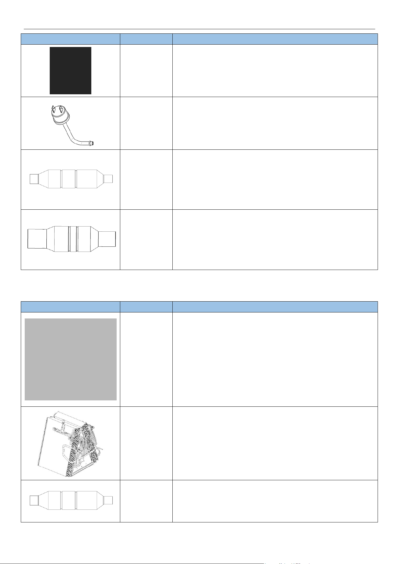
MRCOOL® DC INVERTER GEOTHERMAL HEAT PUMP
60
Picture
Name
Function
Low Pressure
Switch 2
Used for detecting the low-pressure pressure of the unit in ground loop
system. Detect the system low-pressure, in order to protect the unit from
abnormal operation. When the system low-pressure is lower than the set
value, an error will be displayed and the unit will not start or stop.
Low Pressure
Switch 1
Used for detecting the low-pressure pressure of the unit in ground water
system. Detect the system low-pressure, in order to protect the unit from
abnormal operation. When the system low-pressure is lower than the set
value, an error will be displayed and the unit will not start or stop.
One Way Valve
The unit is equipped with two one-way valves, each connected in parallel
in two electronic expansion valve flow paths, to ensure one-way flow of the
refrigerant circuit.
Filter
Located before and after the electronic expansion valve, it is used to filter
impurities in the system and prevent blockage.
5.5.2 Major Components of A-Coil Module
Picture
Name
Function
Electronic
Expansion Valve
The unit is equipped with two electronic expansion valves, located in the
Compressor module and the A-Coil module, respectively, for the control of
heating mode and cooling mode. The function of the electronic expansion
valve is as follows:
1. Throttling and depressurization of high-pressure liquid refrigerant to
ensure the pressure difference between the condenser and evaporator.
2. Adjust the refrigerant flow rate entering the evaporator to adapt to
changes in the heat load of the evaporator and ensure stable operation of
the refrigeration device.
Evaporator
Used for high-temperature and high-pressure gaseous refrigerant
condensing and liquefying or low-temperature and low-pressure refrigerant
evaporating; The condensation heat is carried away by the circulating air
or the heat required for evaporation is provided by the indoor circulating
air.
One Way Valve
The unit is equipped with two one-way valves, each connected in parallel
in two electronic expansion valve flow paths, to ensure one-way flow of the
refrigerant circuit.
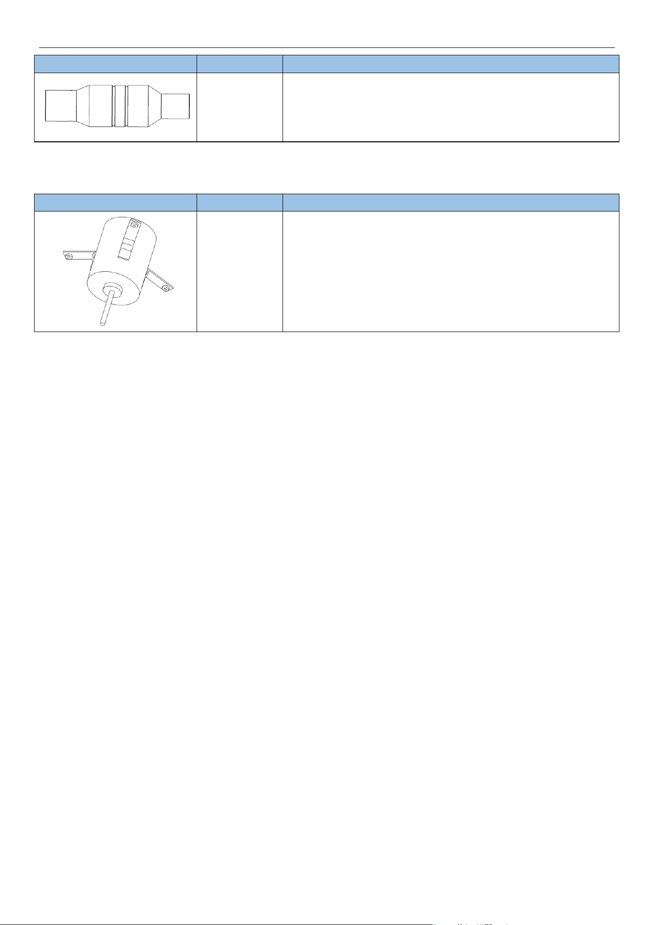
MRCOOL® DC INVERTER GEOTHERMAL HEAT PUMP
61
Picture
Name
Function
Filter
Located before and after the electronic expansion valve, it is used to filter
impurities in the system and prevent blockage.
5.5.3 Major Components of Blower Module
Picture
Name
Function
Motor
The power drive of the fan. It enables the fan to run so as to provide
smooth currents of air for forced convection and heat exchange of
condenser and evaporator.
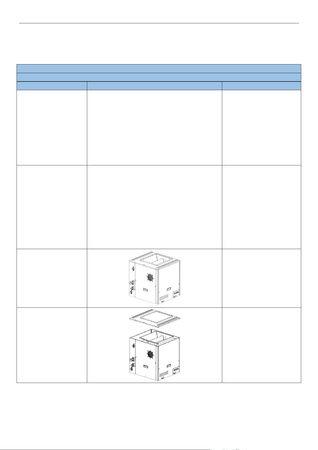
MRCOOL® DC INVERTER GEOTHERMAL HEAT PUMP
62
5.5.4 Removal of Compressor Module Major Components
Model: GCSHPM048IN / GCSHPM060IN
Removal of compressor
NOTE:Before removing the compressor, make sure there is no refrigerant in the pipeline and power is cut off.
Step
Picture
Work instruction
1. Dismantle the screws
Dismantle the four screws
that fix the lid (note: during
the integral installation, the
unit has already removed
this lid, and this step can be
ignored)
2. Remove the lid
Remove the lid (note: during
the integral installation, the
unit has already removed
this lid, and this step can be
ignored)
3. Remove the screws that
secure the top cover
Remove the 23 screws that
secure the top cover
4. Remove the cover
Remove the cover
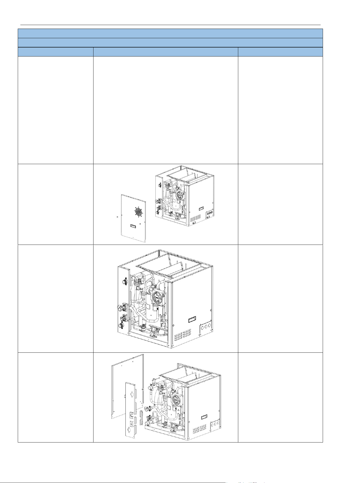
MRCOOL® DC INVERTER GEOTHERMAL HEAT PUMP
63
Removal of compressor
NOTE:Before removing the compressor, make sure there is no refrigerant in the pipeline and power is cut off.
Step
Picture
Work instruction
5. Remove the screws
fixing the Panel (front)
Pull out the two rubber plugs
of the panel (front), and then
remove the five screws fixing
the Panel (front), and the
four bolts fixing the
Computer fan (note: there
are also two screws under
the rubber plug)
6. Remove the Panel (front)
Remove the Panel (front)
7. Remove the screws
fixing the Panel (left) and
Panel (valve)
Pull out the 2 rubber plugs on
the Panel (left), and then
remove the 5 screws that
secure the Panel (left) (note:
there are also two screws
under the rubber plugs)
Dismantle the four screws
that fix the size globe valve,
the four bolts that fix the inlet
and outlet water pipes, and
the two screws that fix the
Panel (valve)
8. Remove the Panel (left)
and Panel (valve)
Remove the panel (left)
Remove the panel (valve)
(Note: Before removing the
panel (valve), it is necessary
to first remove the bracket
next to the fixed bracket of
the large and small shut-off
valves, and fix it with two
screws )

MRCOOL® DC INVERTER GEOTHERMAL HEAT PUMP
64
Removal of compressor
NOTE:Before removing the compressor, make sure there is no refrigerant in the pipeline and power is cut off.
Step
Picture
Work instruction
9. Weld out the interfaces
Weld out the interfaces
marked in the diagram in
preparation for removing the
four way valve components
and compressor
10. Remove the 4-way valve
component
Remove the 4-way valve
component
11. Dismantle the nut
Dismantle the three nuts
securing the compressor
foot pads (note: the two
compressor foot pads in front
of the compressor have been
removed before installation
and operation)
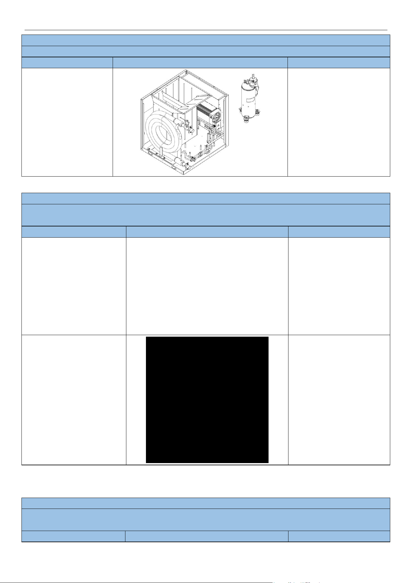
MRCOOL® DC INVERTER GEOTHERMAL HEAT PUMP
65
Removal of compressor
NOTE:Before removing the compressor, make sure there is no refrigerant in the pipeline and power is cut off.
Step
Picture
Work instruction
12. Removing and replacing
the compressor
Removing and replacing the
compressor
Model: GCSHPM048IN / GCSHPM060IN
Removal of 4-Way Valve
NOTE:Before removing the 4-Way valve, make sure there is no refrigerant in the pipeline and power is cut off.
The first ten steps are consistent with the first ten steps of replacing the compressor.
Step
Picture
Work instruction
1. Weld out the interface
Weld out the interface
marked in the diagram in
preparation for replacing the
4-way valve
2. Remove and replace the
four-way valve
Remove and replace the
four-way valve
Model: GCSHPM048IN / GCSHPM060IN
Removal of Co-axial Heat Exchanger
NOTE: Before removing the Co-Axial Heat Exchanger, make sure there is no refrigerant in the pipeline and power is cut off.
The first four steps are consistent with the first four steps of replacing the compressor
Step
Picture
Work instruction
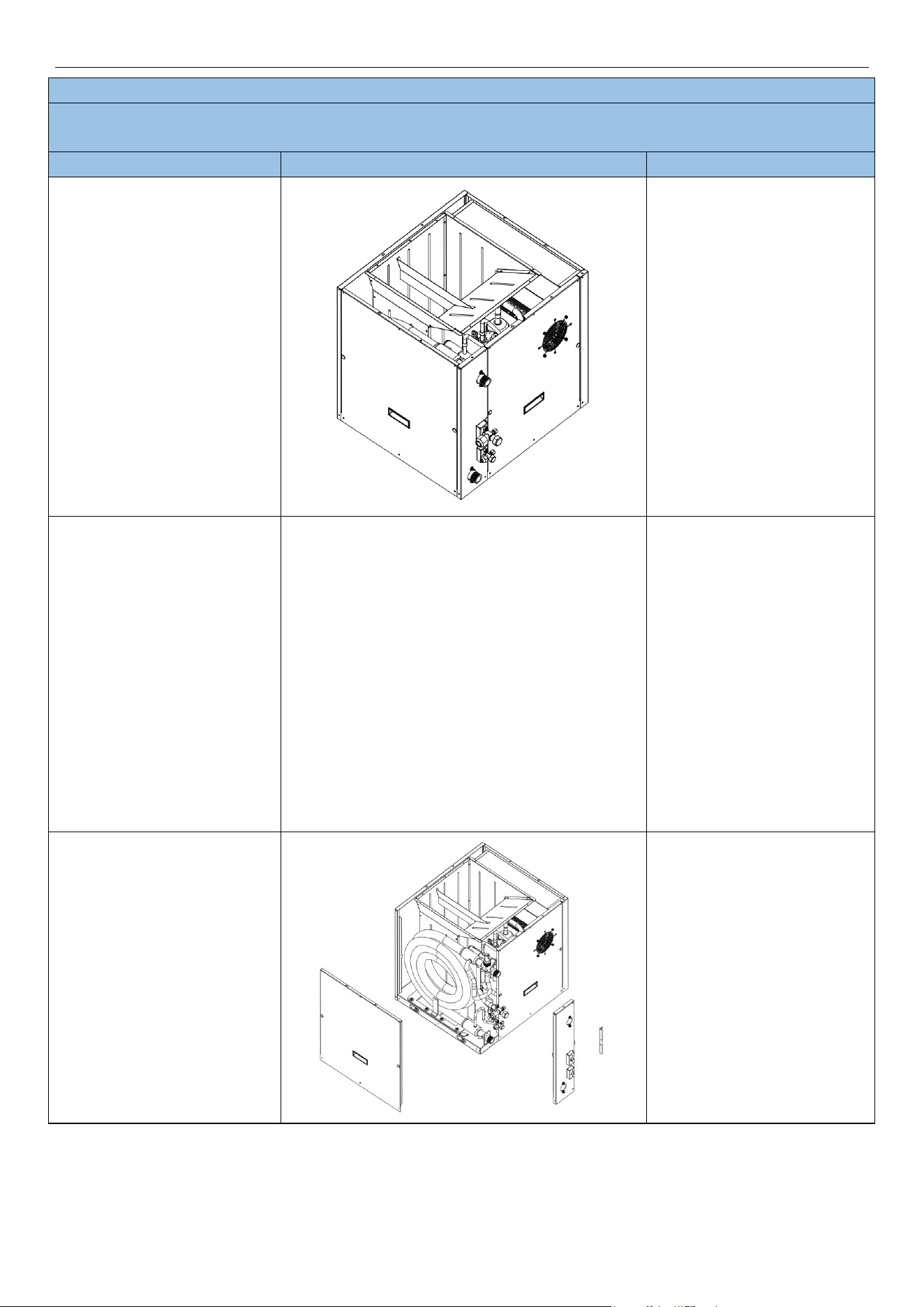
MRCOOL® DC INVERTER GEOTHERMAL HEAT PUMP
66
Removal of Co-axial Heat Exchanger
NOTE: Before removing the Co-Axial Heat Exchanger, make sure there is no refrigerant in the pipeline and power is cut off.
The first four steps are consistent with the first four steps of replacing the compressor
Step
Picture
Work instruction
1. Preparation for replacing the
co-axial heat exchanger
The first four steps are
consistent with the first four
steps of replacing the
compressor
2. Remove the screws fixing the
Panel (left) and Panel (valve)
Pull out the 2 rubber plugs
on the Panel (left), and then
remove the 5 screws that
secure the Panel (left) (note:
there are also two screws
under the rubber plugs)
Dismantle the four screws
that fix the size globe valve,
the four bolts that fix the inlet
and outlet water pipes, and
the two screws that fix the
Panel (valve)
3. Remove the Panel (left) and
Panel (valve)
Remove the Panel (left)
Remove the Panel (valve)
(Note: Before removing the
Panel (valve), it is necessary
to first remove the bracket
next to the fixed bracket of
the large and small shut-off
valves, and fix it with two
screws at the top and
bottom)

MRCOOL® DC INVERTER GEOTHERMAL HEAT PUMP
67
Removal of Co-axial Heat Exchanger
NOTE: Before removing the Co-Axial Heat Exchanger, make sure there is no refrigerant in the pipeline and power is cut off.
The first four steps are consistent with the first four steps of replacing the compressor
Step
Picture
Work instruction
4. Remove the water flow
switch and inlet/outlet water
temperature sensor
Remove the water flow
switch and inlet/outlet water
temperature sensor
5. Weld out the interfaces
Weld out the interfaces
marked in the diagram in
preparation for removing the
co-axial heat exchanger
6. Dismantle the nuts
Dismantle the four nuts
securing the co-axial heat
exchanger
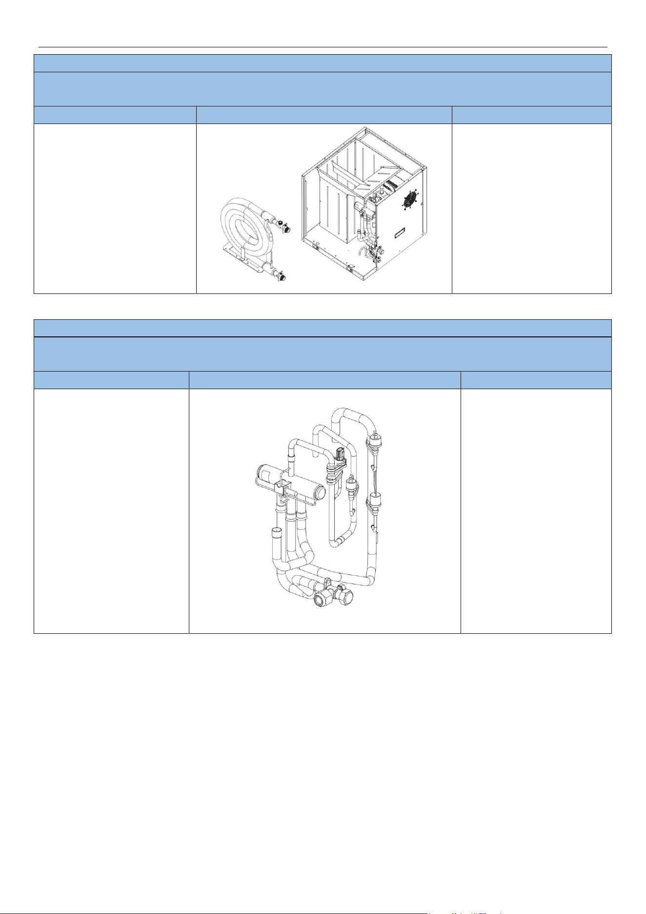
MRCOOL® DC INVERTER GEOTHERMAL HEAT PUMP
68
Removal of Co-axial Heat Exchanger
NOTE: Before removing the Co-Axial Heat Exchanger, make sure there is no refrigerant in the pipeline and power is cut off.
The first four steps are consistent with the first four steps of replacing the compressor
Step
Picture
Work instruction
7. Removing and replacing the
co-axial heat exchanger.
Removing and replacing the
co-axial heat exchanger
Model: GCSHPM048IN / GCSHPM060IN
Removal of pressure sensor/pressure switch
NOTE: Before removing the pressure sensor/pressure switch, make sure there is no refrigerant in the pipeline and power is cut off.
The first ten steps are consistent with the first ten steps of replacing the compressor
Step
Picture
Work instruction
1. Remove the 4-way valve
component
The first ten steps are
consistent with the first ten
steps of compressor
replacement

MRCOOL® DC INVERTER GEOTHERMAL HEAT PUMP
69
Removal of pressure sensor/pressure switch
NOTE: Before removing the pressure sensor/pressure switch, make sure there is no refrigerant in the pipeline and power is cut off.
The first ten steps are consistent with the first ten steps of replacing the compressor
Step
Picture
Work instruction
2. Remove and replace the
high pressure sensor
Remove the pipe fixing
block and wire tie for fixing
the pressure sensor
Welding off the pressure
sensor interface
Remove and replace the
high pressure sensor
3. Remove and replace the
high pressure switch
Remove the pipe fixing
block and wire tie of the
fixed high pressure switch
Weld out the interface of
the high pressure switch
Remove and replace the
high pressure switch
4. Remove and replace the
pressure switch low
pressure switch 2
Remove the pipe fixing
block and wire tie of the
fixed pressure low
pressure switch 2
Weld off the interface of
the low pressure switch 2
Remove the pressure
switch low pressure switch
2 and replace it

MRCOOL® DC INVERTER GEOTHERMAL HEAT PUMP
70
Removal of pressure sensor/pressure switch
NOTE: Before removing the pressure sensor/pressure switch, make sure there is no refrigerant in the pipeline and power is cut off.
The first ten steps are consistent with the first ten steps of replacing the compressor
Step
Picture
Work instruction
5. Remove and replace the
low pressure switch 1
Remove the pipe fixing
block and wire tie that fix
the low pressure switch 1
Weld off the interface of
the low pressure switch 1
Remove and replace the
low pressure switch 1
Model: GCSHPM048IN / GCSHPM060IN
Removal of Electronic Expansion Valve
NOTE: Before removing the Electronic Expansion Valve, make sure there is no refrigerant in the pipeline and power is cut off.
The first six steps are consistent with the first six steps of replacing the compressor
Step
Picture
Work instruction
1. Preparation for replacing the
electronic expansion valve
The first six steps are consistent
with the first six steps of
compressor replacement
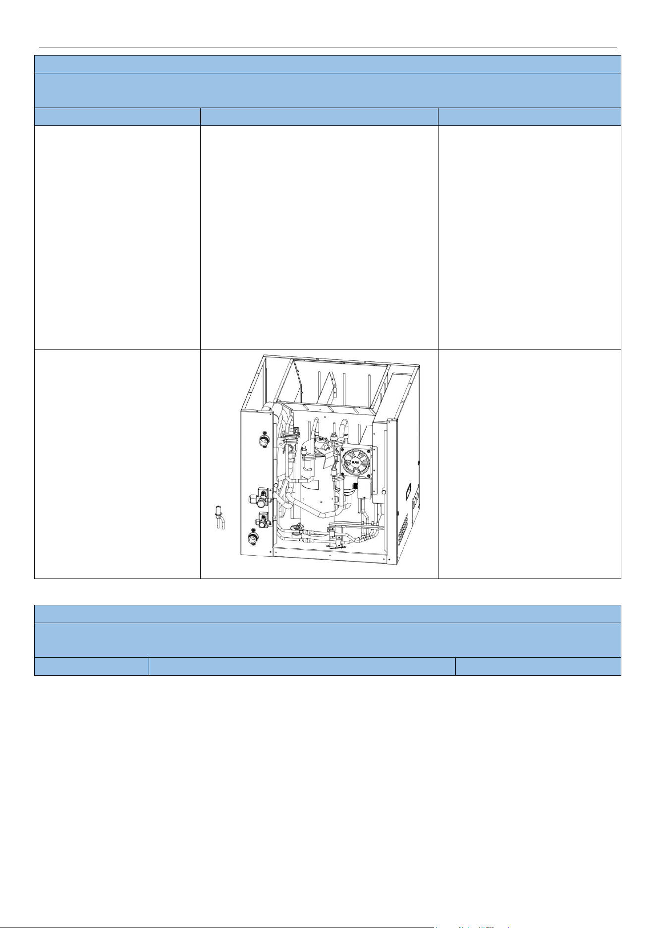
MRCOOL® DC INVERTER GEOTHERMAL HEAT PUMP
71
Removal of Electronic Expansion Valve
NOTE: Before removing the Electronic Expansion Valve, make sure there is no refrigerant in the pipeline and power is cut off.
The first six steps are consistent with the first six steps of replacing the compressor
Step
Picture
Work instruction
2. Remove the fixed bracket of
the electronic expansion
valve
Firstly, remove the fixed bracket
of the electronic expansion valve
Remove the electronic expansion
valve fixing block
Remove the welding interface
3. Remove and replace the
electronic expansion valve
Remove and replace the
electronic expansion valve
Model: GCSHPM048IN / GCSHPM060IN
Removal of Fan
NOTE: Before removing the Fan, make sure power is cut off.
The first six steps are consistent with the first six steps of replacing the compressor
Step
Picture
Work instruction
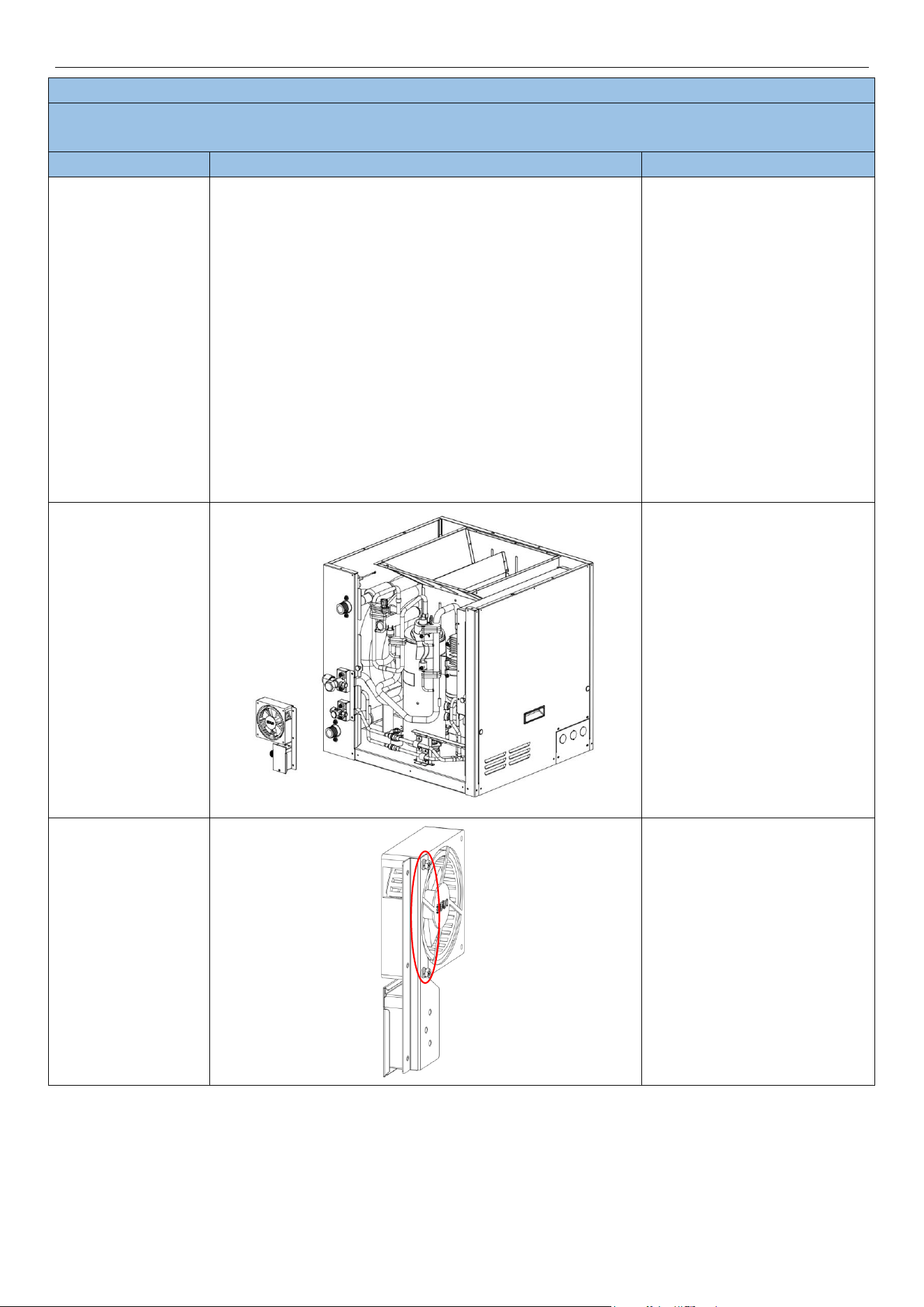
MRCOOL® DC INVERTER GEOTHERMAL HEAT PUMP
72
Removal of Fan
NOTE: Before removing the Fan, make sure power is cut off.
The first six steps are consistent with the first six steps of replacing the compressor
Step
Picture
Work instruction
1. Preparation for
replacing the fan
The first six steps are
consistent with the first six
steps of compressor
replacement.
Remove two screws fixing the
fan.
2. Remove the fan
component
Remove the fan component
3. Remove the
screws fixing the
fan
Remove two screws fixing the
fan
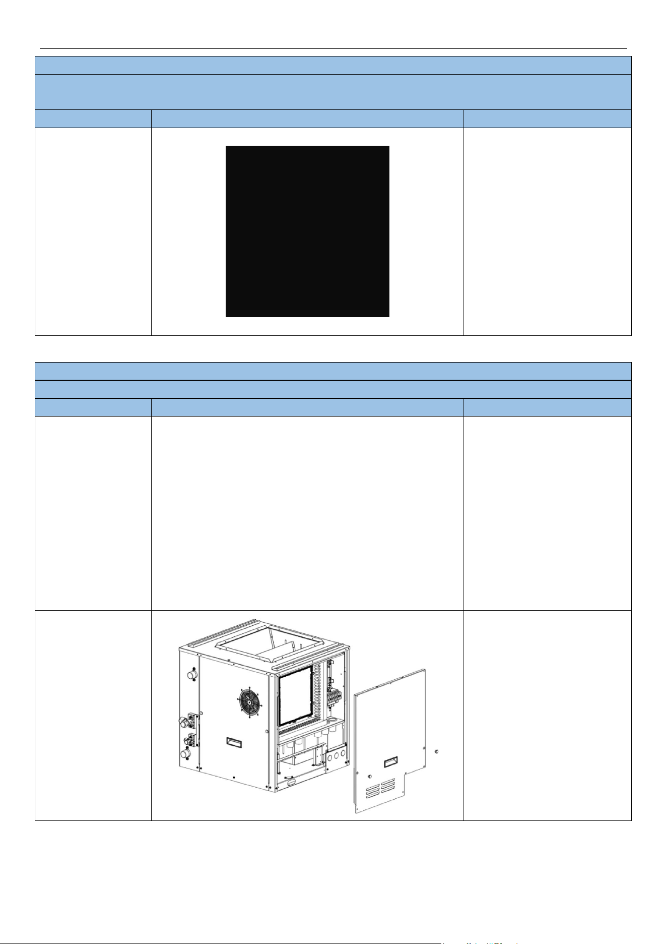
MRCOOL® DC INVERTER GEOTHERMAL HEAT PUMP
73
Removal of Fan
NOTE: Before removing the Fan, make sure power is cut off.
The first six steps are consistent with the first six steps of replacing the compressor
Step
Picture
Work instruction
4. Removing the fan
Removing the fan and
replacing
Model: GCSHPM048IN / GCSHPM060IN
Removal of Radiator
NOTE: Before removing the Radiator, make sure power is cut off.
Step
Picture
Work instruction
1. Removing the
nine screws fixing
the Panel (right)
Pulling out the two rubber
plugs of the Panel (right), and
then removing the nine
screws fixing the Panel (right)
(note: there are also two
screws under the rubber
plug)
2. Remove the right
side panel
Remove the right side panel
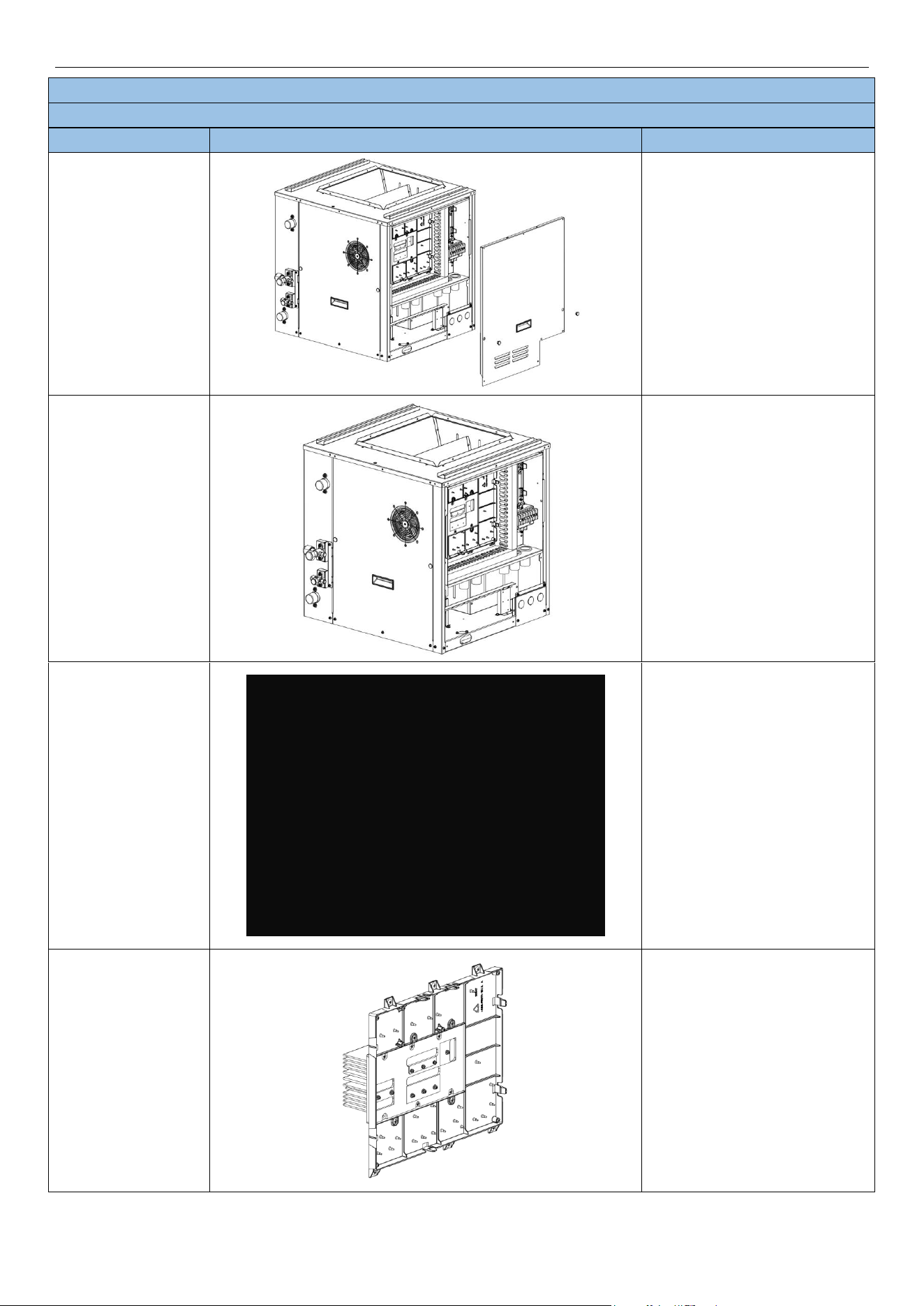
MRCOOL® DC INVERTER GEOTHERMAL HEAT PUMP
74
Removal of Radiator
NOTE: Before removing the Radiator, make sure power is cut off.
Step
Picture
Work instruction
3. Remove the
mainboard
Remove 16 screws that
secure the mainboard and
Remove the mainboard
4. Remove the
screws
Remove the screws that
secure the injection molded
parts of the main board (a
total of 4)
5. Remove the
electrical
retaining plate
Remove the electrical
retaining plate
6. Remove the main
board
Remove all the screws
(totaling 7) that secure the
main board and remove the
main board
MRCOOL® DC INVERTER GEOTHERMAL HEAT PUMP
75
Removal of Radiator
NOTE: Before removing the Radiator, make sure power is cut off.
Step
Picture
Work instruction
7. Replace the
radiator
Remove all the screws (6 in
total) that secure the radiator
and replace it.
Model: GCSHPM048IN / GCSHPM060IN
Removal of Water-Flow Switch
NOTE: Before removing the Water-Flow Switch, make sure power is cut off.
Step
Picture
Work instruction
1. Remove the
screws
Pull out the 2 rubber plugs
on the Panel (left), and then
remove the 8 screws that
secure the Panel (left)
(note: there are also two
screws under the rubber
plugs)
2. Remove the left
side panel
Remove the left side panel
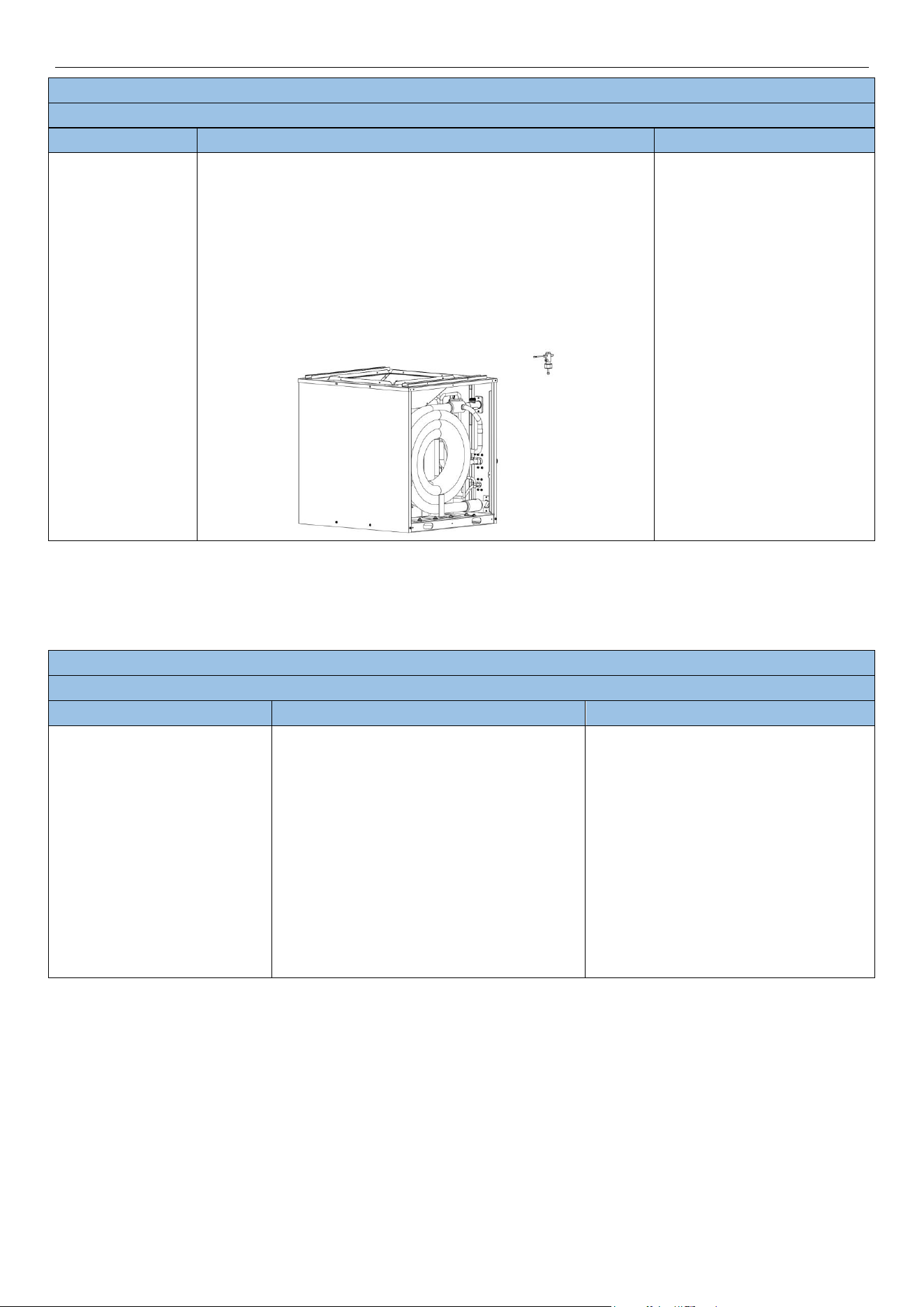
MRCOOL® DC INVERTER GEOTHERMAL HEAT PUMP
76
Removal of Water-Flow Switch
NOTE: Before removing the Water-Flow Switch, make sure power is cut off.
Step
Picture
Work instruction
3. Replace the
water-flow
switch.
Loosen the nut that fixes
the water flow switch to
remove it and replace it
with the inlet and outlet
water temperature sensor
5.5.5 Removal of A-Coil Module Major Components
Model: GCSCAM048GN / GCSCA060GN
Removal of Evaporator
NOTE: Before removing the Evaporator, make sure power is cut off.
Step
Picture
Work instruction
1. Remove the screws
● Remove the nine screws from the cover
assembly 3.

MRCOOL® DC INVERTER GEOTHERMAL HEAT PUMP
77
Removal of Evaporator
NOTE: Before removing the Evaporator, make sure power is cut off.
Step
Picture
Work instruction
2. Remove cover plate
● Remove cover plate assembly 3.
3. Remove the screws
● Remove all screws from the top cover
and cover plate components (1 and 2).
Note that the screws securing the valve
also need to be removed.
4. Remove the top cover and
cover plate
● Remove the top cover and cover plate
components (1, 2).
5. Remove the screws
● Remove the screws that secure the
bracket of the electrical box and the fixing
plate of the drain pan. Note that there are
also fixing screws between the bracket of
the electrical box and the evaporator.
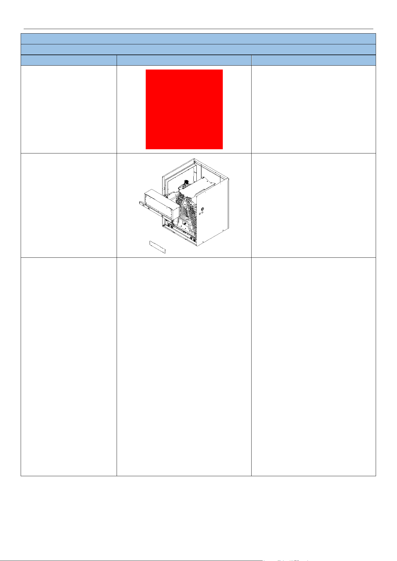
MRCOOL® DC INVERTER GEOTHERMAL HEAT PUMP
78
Removal of Evaporator
NOTE: Before removing the Evaporator, make sure power is cut off.
Step
Picture
Work instruction
6. Remove the screws
● Remove the fixing screws between the
electrical box bracket and the evaporator.
7. Remove the electrical box
bracket and the drain pan fixing
plate.
● Remove the electrical box bracket and
the drain pan fixing plate.
8.Pull the evaporator
components out
● Pull the evaporator components out in
the direction shown.
MRCOOL® DC INVERTER GEOTHERMAL HEAT PUMP
79
Removal of Evaporator
NOTE: Before removing the Evaporator, make sure power is cut off.
Step
Picture
Work instruction
9. Remove the screws
● Remove the fixing screws of the
evaporator and the drain pan, with 3
screws in the front and 3 screws in the
back, totaling 6 screws.
10. Remove the evaporator.
● Remove the evaporator.
Model: GCSCAM048GN / GCSCA060GN
Removal of Main Board
NOTE: Before removing the Main Board, make sure power is cut off.
Step
Picture
Work instruction
1. Remove the screws
● Remove the nine screws from the cover
assembly 3.

MRCOOL® DC INVERTER GEOTHERMAL HEAT PUMP
80
Removal of Main Board
NOTE: Before removing the Main Board, make sure power is cut off.
Step
Picture
Work instruction
2. Remove cover plate
● Remove cover plate assembly 3.
3. Remove the screws
● Remove all screws from the top cover
and cover plate components (1 and 2).
Note that the screws securing the valve
also need to be removed.
4.Remove the top cover and
cover plate
● Remove the top cover and cover plate
components (1, 2).

MRCOOL® DC INVERTER GEOTHERMAL HEAT PUMP
81
Removal of Main Board
NOTE: Before removing the Main Board, make sure power is cut off.
Step
Picture
Work instruction
5. Remove the screws
● Remove the screws that secure the
electrical box bracket. Note that there are
also fixing screws between the electrical
box bracket and the evaporator.
6. Remove the screws
● Remove the fixing screws between the
electrical box bracket and the evaporator.
7.Remove the screws
● Remove the six screws from the
electrical box cover.

MRCOOL® DC INVERTER GEOTHERMAL HEAT PUMP
82
Removal of Main Board
NOTE: Before removing the Main Board, make sure power is cut off.
Step
Picture
Work instruction
8.Remove the electrical box
cover
● Remove the electrical box cover and
remove the three screws of the bracket
assembly. Remove all wiring from the
wiring board and main board.
9.Remove the bracket assembly
● Remove the bracket assembly and
wiring board (6-position), and remove the
four screws that secure the main board.
10.Remove the main board.
● Remove the main board.
Model: GCSCAM048GN / GCSCA060GN
Removal of Drain Pan
NOTE: Before removing the Drain Pan, make sure power is cut off.
Step
Picture
Work instruction

MRCOOL® DC INVERTER GEOTHERMAL HEAT PUMP
83
Removal of Drain Pan
NOTE: Before removing the Drain Pan, make sure power is cut off.
Step
Picture
Work instruction
1. Remove the screws
● Remove the nine screws from the cover
assembly 3.
2. Remove cover plate
● Remove cover plate assembly 3.
3. Remove the screws
● Remove all screws from the top cover
and cover plate components (1 and 2).
Note that the screws securing the valve
also need to be removed.
4. Remove the top cover and
cover plate
● Remove the top cover and cover plate
components (1, 2).
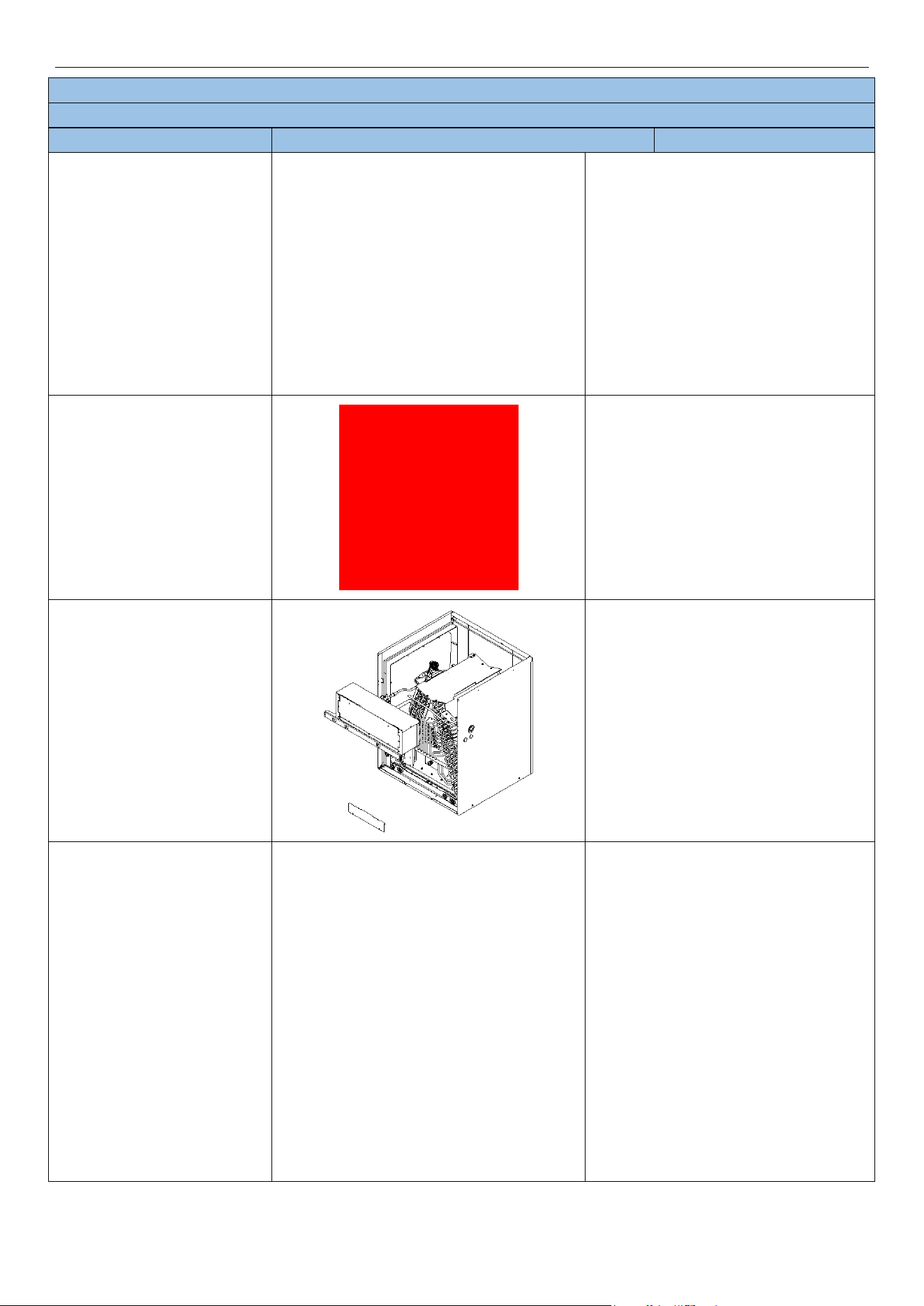
MRCOOL® DC INVERTER GEOTHERMAL HEAT PUMP
84
Removal of Drain Pan
NOTE: Before removing the Drain Pan, make sure power is cut off.
Step
Picture
Work instruction
5. Remove the screws
● Remove the screws that secure the
bracket of the electrical box and the fixing
plate of the drain pan. Note that there are
also fixing screws between the bracket of
the electrical box and the evaporator.
6. Remove the screws
● Remove the fixing screws between the
electrical box bracket and the evaporator.
7. Remove the electrical box
bracket and the drain pan fixing
plate.
● Remove the electrical box bracket and
the drain pan fixing plate.
8.Pull the evaporator
components out
● Pull the evaporator components out in
the direction shown.
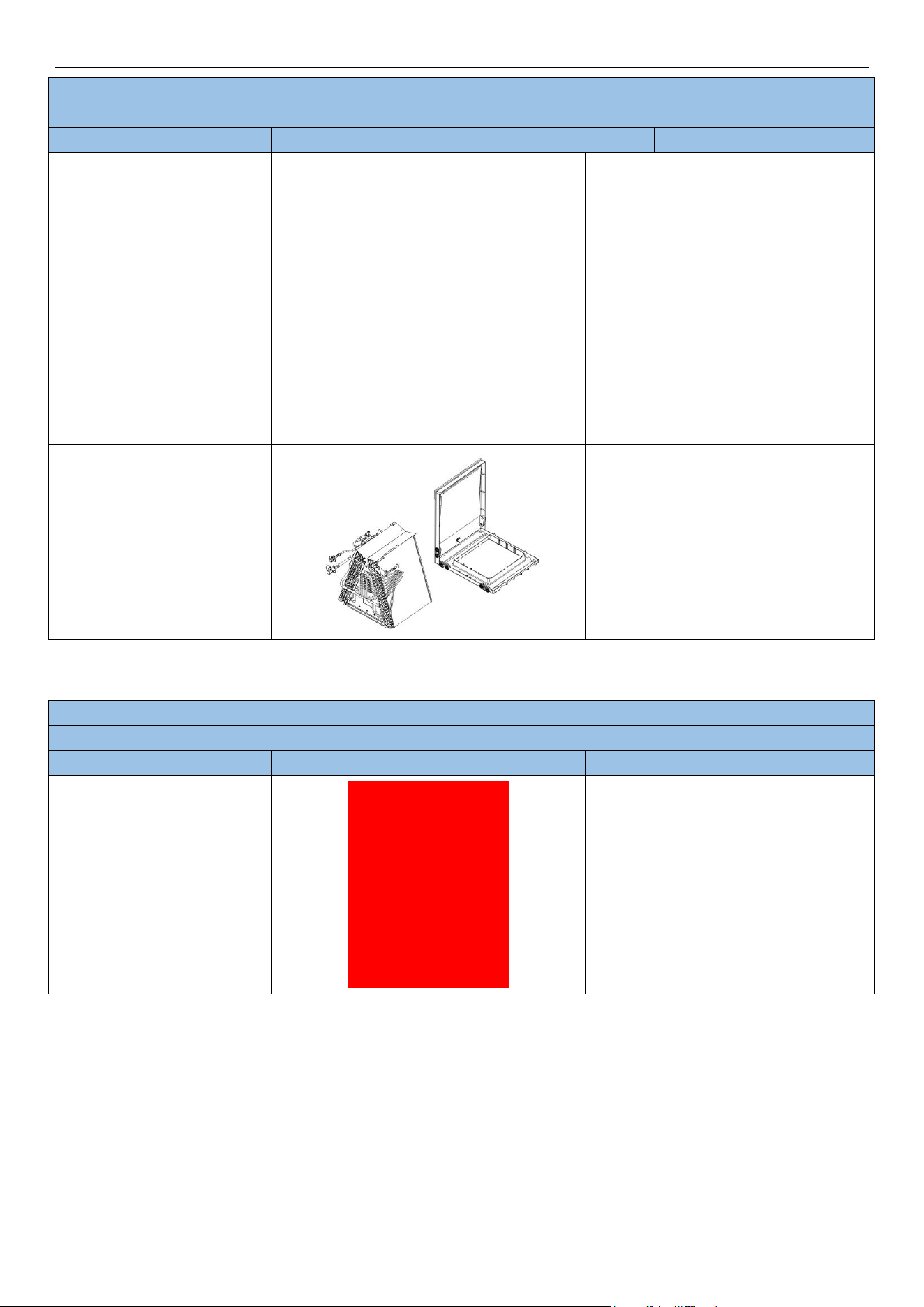
MRCOOL® DC INVERTER GEOTHERMAL HEAT PUMP
85
Removal of Drain Pan
NOTE: Before removing the Drain Pan, make sure power is cut off.
Step
Picture
Work instruction
9. Remove the screws
● Remove the fixing screws of the
evaporator and the drain pan, with 3
screws in the front and 3 screws in the
back, totaling 6 screws.
10 Remove the evaporator.
● Remove the evaporator and replace
the drain pan.
Model: GCSCAM048GN / GCSCA060GN
Removal of Electronic Expansion Valve
NOTE: Before removing the Electronic Expansion Valve, make sure power is cut off.
Step
Picture
Work instruction
1.Rotate the electronic expansion
valve
● Rotate the electronic expansion valve
to make it detachable.
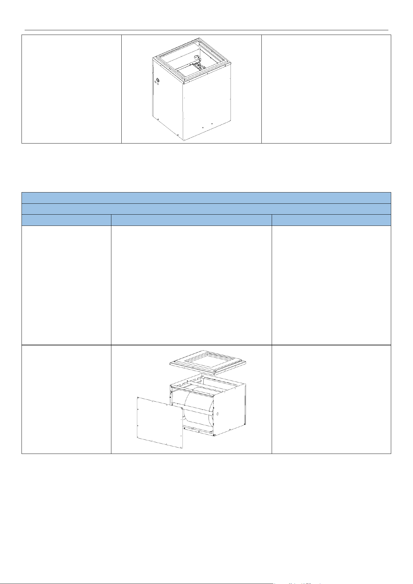
MRCOOL® DC INVERTER GEOTHERMAL HEAT PUMP
86
2.Remove and replace the
electronic expansion valve.
● Remove and replace the electronic
expansion valve.
5.5.3 Removal of Blower Module Major Components
Model: GCSBLM013 / GCSBLM014
Removal of Blower
NOTE: Before removing the Blower, make sure power is cut off.
Step
Picture
Work instruction
1.Remove the screws
● Remove twenty screws from the top
cover and front panel.
2. Remove the top cover and
front panel.
● Remove the top cover and front
panel.
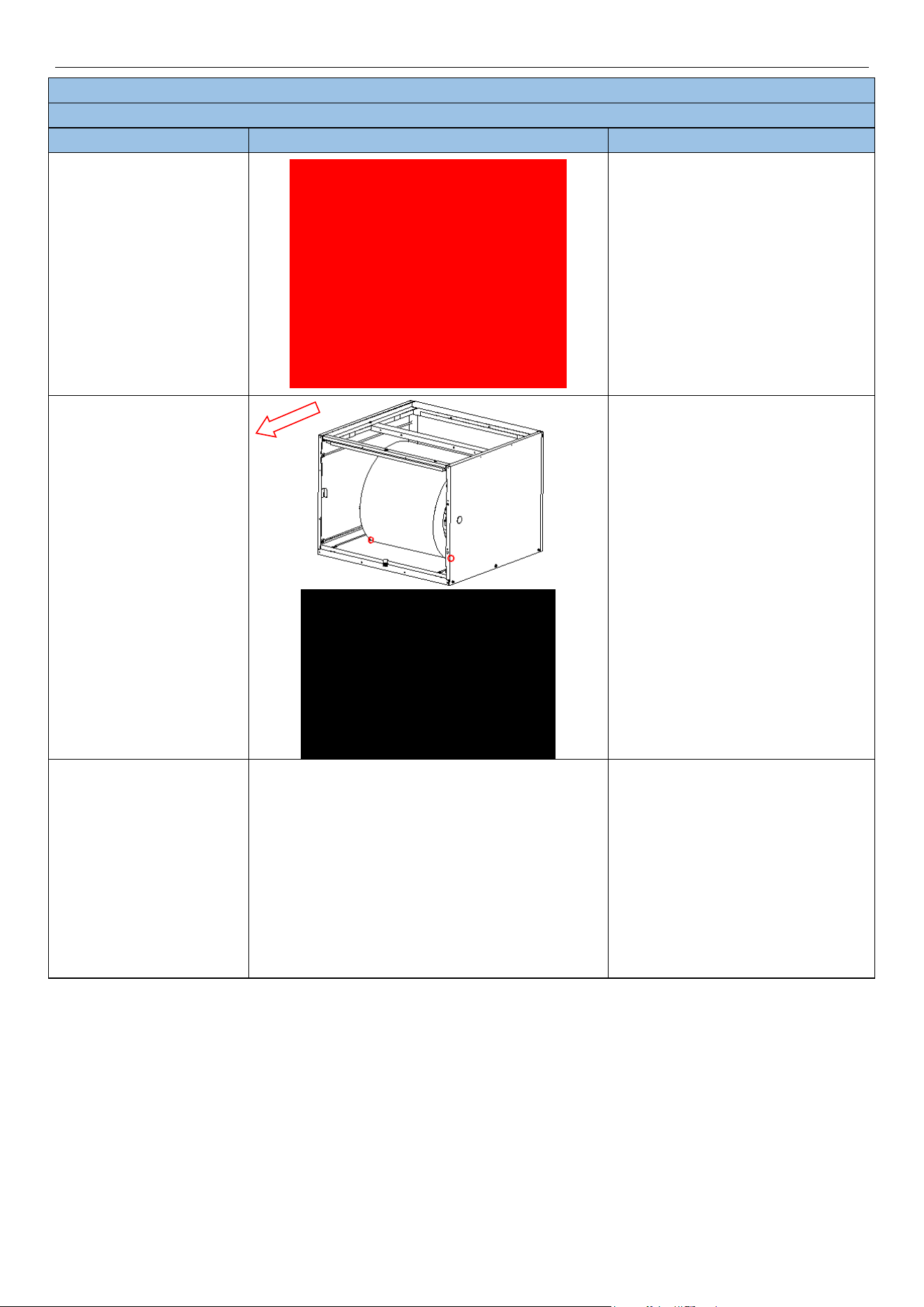
MRCOOL® DC INVERTER GEOTHERMAL HEAT PUMP
87
Removal of Blower
NOTE: Before removing the Blower, make sure power is cut off.
Step
Picture
Work instruction
3. Remove the screws and
fixed bracket.
● Remove the fixing bracket screws
(two in total);
● Remove the fixed bracket.
4.Remove the blower.
● Remove the two screws that secure
the fan
● Drag the blower out in that direction
5.Replace the motor
● Remove the three bolt assemblies
that secure the motor and replace the
motor
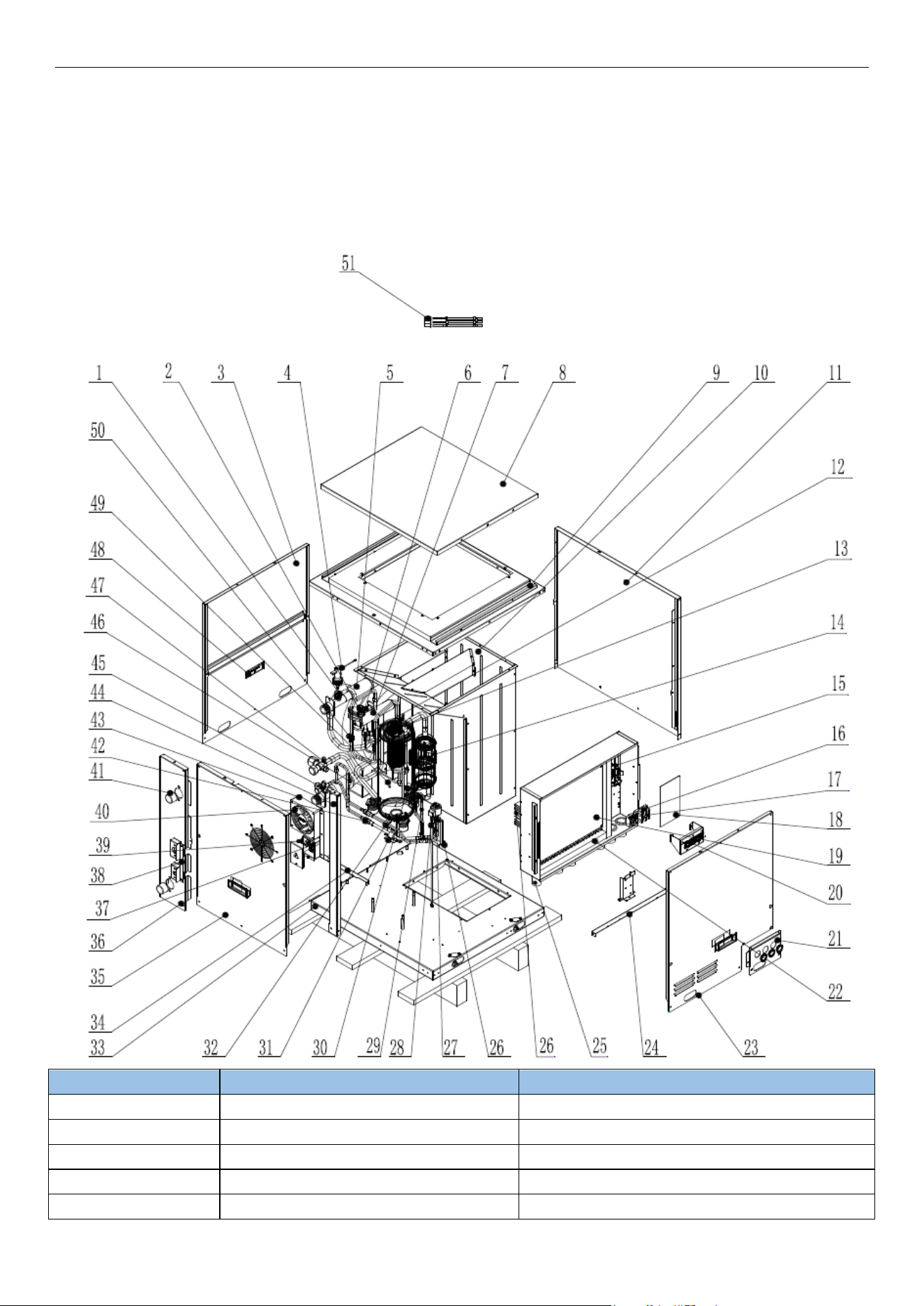
MRCOOL® DC INVERTER GEOTHERMAL HEAT PUMP
88
5.6 Explosive View and Lists of Parts
5.6.1 Compressor Module Explosive View and Lists of Parts
Model:
GCSHPM060IN
No.
Material name
Part Number
1
O-Ring
760010000026
2
High Pressure Sensor
43004400001503
3
Front Panel Sub-Assy
209004060461
4
Water Flow Switch
430019000006
5
Double Pipe Heat Exchanger
010011060075

MRCOOL® DC INVERTER GEOTHERMAL HEAT PUMP
89
No.
Material name
Part Number
6
4 Way Valve Coil
07201006000603
7
4-Way Valve
43000338
8
Lid
012035062355P
9
Top Cover Sub-Assy
017069060114P
10
Air Duct Sub-assy
017107060214
11
Front Panel
209004060460
12
High Pressure Switch
46020006
13
Low Pressure Switch(Ground Water)
460200044
14
Low Pressure Switch(Ground Loop)
4602001596
15
Electrical Retaining Plate
20022700000101
16
Terminal Board
42200006001201
17
Terminal Board
42000100000102
18
Filter Board
300020060118
19
Main Board
300027063069
20
Terminal Board
422000000010
21
Connection Board
012077062176P
22
Electric Raceway
4201030203
23
Front Panel Sub-Assy
209004060463
24
Supporter
012060084641P
25
Rubber Band
7661280504
26
Radiator
430034060222
27
Electric Expand Valve Fitting
4304413266
28
Electronic Expansion Valve
072009060008
29
One Way Valve
071001060011
30
Sensor Insert
42020063
31
Supporter
012060086009P
32
Tube Clip
021400053P
33
Base Frame Assy
000043060667
34
Supporter
012060084642P
35
Front Panel Sub-Assy
209004060455
36
Front Panel Sub-Assy
209004060448
37
Terminal Board
42010185
38
Supporter
012060086133P
39
Cable-Cross Loop
765100263
40
Fan(radiation)
49010501
41
Rubber cover
22240007
42
Filter
035021060019
43
Electric Box Assy
100002080271
44
Front Panel
012073063661P
45
Cut-off valve 3/8(N)
071302391
46
Temp Sensor Sleeving
05212423
47
Cut off Valve
070001000009
48
Handle
2690410001601
49
Compressor and Fittings
009001060898
50
Temperature Sensor clamp
02145007
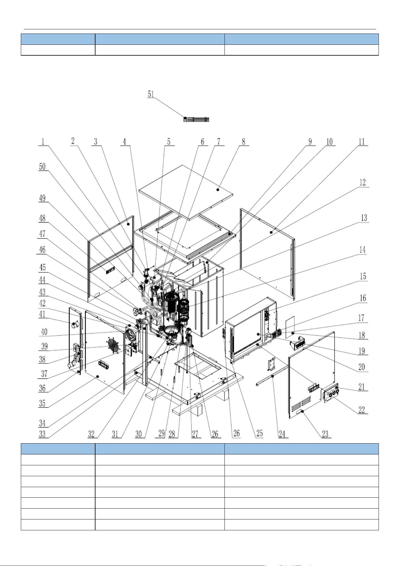
MRCOOL® DC INVERTER GEOTHERMAL HEAT PUMP
90
No.
Material name
Part Number
51
Sensor Sub-assy
390002060442
Model: GCSHPM048IN
No.
Material name
Part Number
1
O-Ring
760010000026
2
High Pressure Sensor
43004400001503
3
Front Panel Sub-Assy
209004060461
4
Water Flow Switch
430019000006
5
Double Pipe Heat Exchanger
010011060075
6
4 Way Valve Coil
07201006000603
7
4-Way Valve
43000338

MRCOOL® DC INVERTER GEOTHERMAL HEAT PUMP
91
No.
Material name
Part Number
8
Lid
012035062355P
9
Top Cover Sub-Assy
017069060114P
10
Air Duct Sub-assy
017107060214
11
Front Panel
209004060460
12
High Pressure Switch
46020006
13
Low Pressure Switch(Ground Water)
460200044
14
Low Pressure Switch(Ground Loop)
4602001596
15
Electrical Retaining Plate
20022700000101
16
Terminal Board
42200006001201
17
Terminal Board
42000100000102
18
Filter Board
300020060118
19
Main Board
300027063706
20
Terminal Board
422000000010
21
Connection Board
012077062176P
22
Electric Raceway
4201030203
23
Front Panel Sub-Assy
209004060463
24
Supporter
012060084641P
25
Rubber Band
7661280504
26
Radiator
430034060222
27
Electric Expand Valve Fitting
4304413266
28
Electronic Expansion Valve
072009060008
29
One Way Valve
071001060011
30
Sensor Insert
42020063
31
Supporter
012060086009P
32
Tube Clip
021400053P
33
Base Frame Assy
000043060667
34
Supporter
012060084642P
35
Front Panel Sub-Assy
209004060455
36
Front Panel Sub-Assy
209004060448
37
Terminal Board
42010185
38
Supporter
012060086133P
39
Cable-Cross Loop
765100263
40
Fan(radiation)
49010501
41
Rubber cover
22240007
42
Filter
035021060019
43
Electric Box Assy
100002080271
44
Front Panel
012073063661P
45
Cut-off valve 3/8(N)
071302391
46
Temp Sensor Sleeving
05212423
47
Cut off Valve
070001000009
48
Handle
2690410001601
49
Compressor and Fittings
009001060898
50
Temperature Sensor clamp
02145007
51
Sensor Sub-assy
390002060442

MRCOOL® DC INVERTER GEOTHERMAL HEAT PUMP
92
5.6.2 A-Coil Module Explosive View and Lists of Parts
Model: GCSCAM060GN
No.
Material name
Part Number
1
Rear Side Plate Sub-Assy
017051060175
2
Filter
035021060019
3
Evaporator Assy
011001062780
4
Right Side Plate Sub-Assy
000130060170
5
Air Outlet Frame Sub-assy
000117060028
6
Water Tray
2690220601
7
Sensor Insert
42020063

MRCOOL® DC INVERTER GEOTHERMAL HEAT PUMP
93
No.
Material name
Part Number
8
Choke Plug
76718209
9
Retaining Plate (Water Level Switch)
012066062210
10
Support Assy
000157060222
11
Cable-Cross Loop
765100263
12
Cover Plate Sub-Assy
011657060546
13
Plastic Cover
26902209
14
Cover Plate Sub-Assy
011657060547
15
Cover Plate Sub-Assy
011657060556
16
Electric Box Cover
012020061074P
17
Electric Box Assy
100002078180
18
Rubber Band
7661280504
19
Rubber Band
7661280503
20
Support Assy
000157060224
21
Cut off Valve 3/4N
070001000009
22
Temp Sensor Sleeving
05212423
23
Cut off Valve 3/8N
071302391
24
Water Tray
2690220501
25
One Way Valve
071001060012
26
Tube Clip
021400053P
27
Electronic Expansion Valve
072009060008
28
Left Side Plate Sub-Assy
017037060351
29
Electric Expand Valve Fitting
07200206002329
30
Support Assy
000157060223
31
Top Cover Sub-Assy
000051060221
32
Transformer
43110286
33
Terminal Board
422000060007
34
Main Board
300002063486
35
Cable Cross Loop
76510021
36
Terminal Board
42000100000102
37
Cable Cross Loop
76510021

MRCOOL® DC INVERTER GEOTHERMAL HEAT PUMP
94
Model: GCSCAM048GN
No.
Material name
Part Number
1
Rear Side Plate Sub-Assy
017051060175
2
Filter
035021060019
3
Evaporator Assy
011001062780
4
Right Side Plate Sub-Assy
000130060170
5
Air Outlet Frame Sub-assy
000117060028
6
Water Tray
2690220601
7
Sensor Insert
42020063
8
Choke Plug
76718209

MRCOOL® DC INVERTER GEOTHERMAL HEAT PUMP
95
No.
Material name
Part Number
9
Retaining Plate (Water Level Switch)
012066062210
10
Support Assy
000157060222
11
Cable-Cross Loop
765100263
12
Cover Plate Sub-Assy
011657060546
13
Plastic Cover
26902209
14
Cover Plate Sub-Assy
011657060547
15
Cover Plate Sub-Assy
011657060556
16
Electric Box Cover
012020061074P
17
Electric Box Assy
100002081473
18
Rubber Band
7661280504
19
Rubber Band
7661280503
20
Support Assy
000157060224
21
Cut off Valve 3/4N
070001000009
22
Temp Sensor Sleeving
05212423
23
Cut off Valve 3/8N
071302391
24
Water Tray
2690220501
25
One Way Valve
071001060012
26
Tube Clip
021400053P
27
Electronic Expansion Valve
072009060008
28
Left Side Plate Sub-Assy
017037060351
29
Electric Expand Valve Fitting
07200206002329
30
Support Assy
000157060223
31
Top Cover Sub-Assy
000051060221
32
Transformer
43110286
33
Terminal Board
422000060007
34
Main Board
300002063947
35
Cable Cross Loop
76510021
36
Terminal Board
42000100000102
37
Cable Cross Loop
76510021
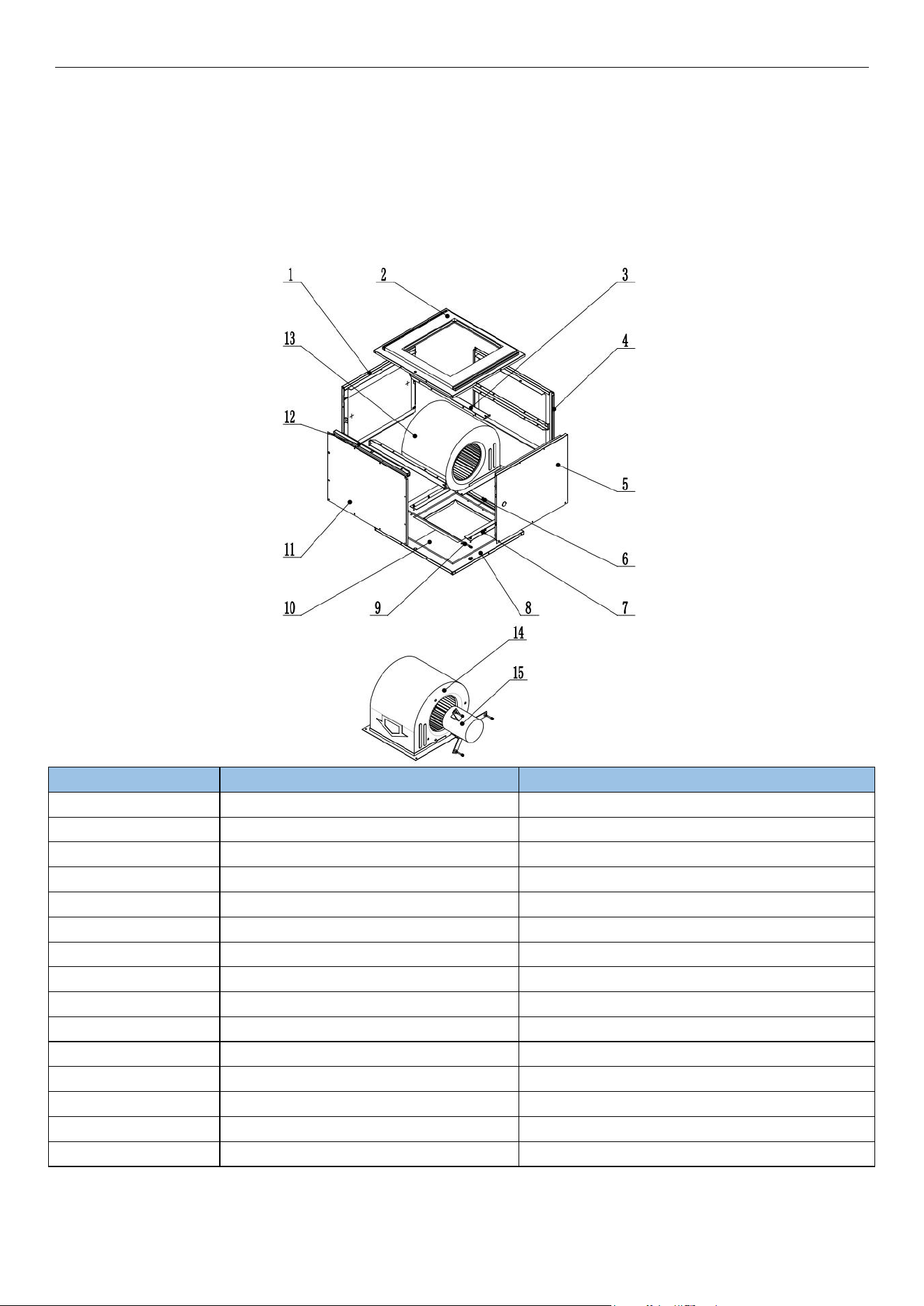
MRCOOL® DC INVERTER GEOTHERMAL HEAT PUMP
96
5.6.3 Blower Module Explosive View and Lists of Parts
Model: GCSBLM013 / GCSBLM014
No.
Material name
Part Number
1
Front Panel Sub-Assy
209004060428
2
Top Cover Sub-Assy
000051060226
3
Supporter
012060084723P
4
Front Panel Sub-Assy
209004060427
5
Front Panel Sub-Assy
209004060429
6
Retaining Plate Sub-Assy
017032060759
7
Fan fixing plate assembly 1
01842232
8
Cover Plate Sub-Assy
011657060549P
9
Wire
012222000025
10
Sponge
110000076297
11
Front Panel Sub-Assy
209004060430
12
Support Assy
000157060233
13
Centrifugal fan assy
000052060818
14
Centrifugal Fan Housing
1570220301
15
Brushless DC Motor
15010400001304

MRCOOL® DC INVERTER GEOTHERMAL HEAT PUMP
97
5 COMMON PARAMETER LISTS
5.1 Temperature/Pressure List of Refrigerant
R410A
Temperature
Pressure
Temperature
Pressure
Temperature
Pressure
℃
kPa
℃
kPa
℃
kPa
-30
275
0
803
30
1880
-29
286
1
823
31
1910
-28
298
2
851
32
1960
-27
311
3
879
33
2030
-26
324
4
903
34
2080
-25
334
5
937
35
2130
-24
348
6
962
36
2180
-23
363
7
994
37
2240
-22
375
8
1020
38
2290
-21
391
9
1050
39
2350
-20
404
10
1090
40
2410
-19
424
11
1110
41
2460
-18
435
12
1150
42
2510
-17
453
13
1180
43
2580
-16
468
14
1220
44
2650
-15
483
15
1250
45
2710
-14
504
16
1280
46
2770
-13
520
17
1320
47
2840
-12
538
18
1350
48
2910
-11
556
19
1400
49
2980
-10
579
20
1440
50
3050
-9
598
21
1470
51
3100
-8
618
22
1520
52
3180
-7
639
23
1560
53
3250
-6
660
24
1600
54
3320
-5
682
25
1640
55
3400
-4
705
26
1680
56
3480
-3
728
27
1730
57
3540
-2
752
28
1780
58
3630
-1
777
29
1820
59
3720

MRCOOL® DC INVERTER GEOTHERMAL HEAT PUMP
98
5.2 Resistance / Temperature Lists of Temperature Sensors
5.2.1 Voltage list of 15 kΩ temperature sensors (including return air
temperature sensors)
Temp.
(℃)
Resistance
(kΩ)
Voltage
(15K/5V)
Voltage
(15K/3.3V)
Temp.
(℃)
Resistance
(kΩ)
Voltage
(15K/5V)
Voltage
(15K/3.3V)
-20
144
0.472
0.311
25
15
2.5
1.65
-19
138.1
0.49
0.323
26
14.36
2.554
1.686
-18
128.6
0.522
0.345
27
13.74
2.61
1.722
-17
121.6
0.549
0.362
28
13.16
2.663
1.758
-16
115
0.577
0.381
29
12.6
2.717
1.793
-15
108.7
0.606
0.4
30
12.07
2.771
1.829
-14
102.9
0.636
0.42
31
11.57
2.823
1.863
-13
97.4
0.667
0.44
32
11.09
2.875
1.897
-12
92.22
0.699
0.462
33
10.63
2.926
1.931
-11
87.35
0.733
0.484
34
10.2
2.976
1.964
-10
82.75
0.767
0.506
35
9.779
3.027
1.998
-9
78.43
0.803
0.53
36
9.382
3.076
2.03
-8
74.35
0.839
0.554
37
9.003
3.125
2.062
-7
70.5
0.877
0.579
38
8.642
3.172
2.094
-6
66.88
0.916
0.605
39
8.297
3.219
2.125
-5
63.46
0.956
0.631
41
7.653
3.311
2.185
-4
60.23
0.997
0.658
42
7.352
3.355
2.215
-3
57.18
1.039
0.686
43
7.065
3.399
2.243
-2
54.31
1.082
0.714
44
6.791
3.442
2.272
-1
51.59
1.126
0.743
45
6.529
3.484
2.299
0
49.02
1.172
0.773
46
6.278
3.525
2.326
1
46.8
1.214
0.801
47
6.038
3.565
2.353
2
44.31
1.265
0.835
48
5.809
3.604
2.379
3
42.14
1.313
0.866
49
5.589
3.643
2.404
4
40.09
1.361
0.899
50
5.379
3.68
2.429
5
38.15
1.411
0.931
51
5.179
3.717
2.453
6
36.32
1.461
0.965
52
4.986
3.753
2.477
7
34.58
1.513
0.998
53
4.802
3.787
2.5
8
32.94
1.564
1.033
54
4.625
3.822
2.522
9
31.38
1.617
1.067
55
4.456
3.855
2.544
10
29.9
1.67
1.102
56
4.294
3.887
2.566
11
28.51
1.724
1.138
57
4.139
3.919
2.586
12
27.18
1.778
1.174
58
3.99
3.949
2.607
13
25.92
1.833
1.21
59
3.848
3.979
2.626
14
24.73
1.888
1.246
60
3.711
4.008
2.646
15
23.6
1.943
1.282
61
3.579
4.037
2.664
16
22.53
1.998
1.319
62
3.454
4.064
2.682

MRCOOL® DC INVERTER GEOTHERMAL HEAT PUMP
99
17
21.51
2.054
1.356
63
3.333
4.091
2.7
18
20.54
2.11
1.393
64
3.217
4.117
2.717
19
19.63
2.166
1.429
65
3.105
4.143
2.734
20
18.75
2.222
1.467
66
2.998
4.167
2.75
21
17.93
2.278
1.503
67
2.898
4.19
2.766
22
17.14
2.334
1.54
68
2.797
4.214
2.781
23
16.39
2.389
1.577
69
2.702
4.237
2.796
24
15.68
2.445
1.613
70
2.611
4.259
2.811

MRCOOL® DC INVERTER GEOTHERMAL HEAT PUMP
100
5.2.2 Voltage list of 20 kΩ pipeline temperature sensors (including temperature
sensors for water inlet, water outlet, liquid/gas pipe, suction, in-tube)
Temp.
(℃)
Resistance
(kΩ)
Voltage
(15K/5V)
Voltage
(15K/3.3V)
Temp.
(℃)
Resistance
(kΩ)
Voltage
(15K/5V)
Voltage
(15K/3.3V)
-20
196.9
0.461
0.304
28
17.55
2.663
1.758
-19
181.4
0.497
0.328
29
16.8
2.717
1.793
-18
171.4
0.522
0.345
30
16.1
2.77
1.828
-17
162.1
0.549
0.362
31
15.43
2.822
1.863
-16
153.3
0.577
0.381
32
14.79
2.874
1.897
-15
145
0.606
0.4
33
14.18
2.926
1.931
-14
137.2
0.636
0.42
34
13.59
2.977
1.965
-13
129.9
0.667
0.44
35
13.04
3.027
1.998
-12
123
0.699
0.462
36
12.51
3.076
2.03
-11
116.5
0.733
0.484
37
12
3.125
2.063
-10
110.3
0.767
0.507
38
11.52
3.173
2.094
-9
104.6
0.803
0.53
39
11.06
3.22
2.125
-8
99.13
0.839
0.554
40
10.62
3.266
2.155
-7
94
0.877
0.579
41
10.2
3.311
2.185
-6
89.17
0.916
0.605
42
9.803
3.355
2.215
-5
84.61
0.956
0.631
43
9.42
3.399
2.243
-4
80.31
0.997
0.658
44
9.054
3.442
2.272
-3
76.24
1.039
0.686
45
8.705
3.484
2.299
-2
72.41
1.082
0.714
46
8.37
3.525
2.326
-1
68.79
1.126
0.743
47
8.051
3.565
2.353
0
65.37
1.171
0.773
48
7.745
3.604
2.379
1
62.13
1.218
0.804
49
7.453
3.643
2.404
2
59.08
1.265
0.835
50
7.173
3.68
2.429
3
56.19
1.313
0.866
51
6.905
3.717
2.453
4
53.46
1.361
0.898
52
6.648
3.753
2.477
5
50.87
1.411
0.931
53
6.403
3.787
2.5
6
48.42
1.462
0.965
54
6.167
3.822
2.522
7
46.11
1.513
0.998
55
5.942
3.855
2.544
8
43.92
1.564
1.033
56
5.726
3.887
2.565
9
41.84
1.617
1.067
57
5.519
3.919
2.586
10
39.87
1.67
1.102
58
5.32
3.949
2.607
11
38.01
1.724
1.138
59
5.13
3.979
2.626
12
36.24
1.778
1.174
60
4.948
4.008
2.646
13
34.57
1.833
1.209
61
4.773
4.037
2.664
14
32.98
1.888
1.246
62
4.605
4.064
2.682
15
31.47
1.943
1.282
63
4.443
4.091
2.7
16
30.04
1.998
1.319
64
4.289
4.117
2.717
17
28.68
2.054
1.356
65
4.14
4.143
2.734

MRCOOL® DC INVERTER GEOTHERMAL HEAT PUMP
101
18
27.39
2.11
1.393
66
3.998
4.167
2.75
19
26.17
2.166
1.429
67
3.861
4.191
2.766
20
25.01
2.222
1.466
68
3.729
4.214
2.781
21
23.9
2.278
1.503
69
3.603
4.237
2.796
22
22.85
2.334
1.54
70
3.481
4.259
2.811
23
21.85
2.389
1.577
71
3.364
4.28
2.825
24
20.9
2.445
1.614
72
3.252
4.301
2.838
25
20
2.5
1.65
73
3.144
4.321
2.852
26
19.14
2.555
1.686
74
3.04
4.34
2.865
27
18.32
2.61
1.722
75
2.94
4.359
2.877
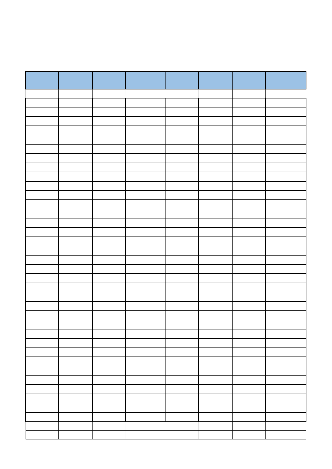
MRCOOL® DC INVERTER GEOTHERMAL HEAT PUMP
102
5.2.3 Voltage list of 50 kΩ discharge temperature sensors (including discharge
air temperature sensor)
Temp.
(℃)
Resistance
(kΩ)
Voltage
(15K/5V)
Voltage
(15K/3.3V)
Temp.
(℃)
Resistance
(kΩ)
Voltage
(15K/5V)
Voltage
(15K/3.3V)
-30
911.56
0.054
0.036
8
107.96
0.424
0.28
-29
853.66
0.058
0.038
9
102.85
0.443
0.292
-28
799.98
0.062
0.041
10
98.006
0.463
0.306
-27
750.18
0.066
0.043
11
93.42
0.483
0.319
-26
703.92
0.07
0.046
12
89.075
0.505
0.333
-25
660.93
0.075
0.049
13
84.956
0.527
0.348
-24
620.94
0.079
0.052
14
81.052
0.549
0.362
-23
583.72
0.084
0.056
15
77.349
0.572
0.378
-22
549.04
0.089
0.059
16
73.896
0.596
0.393
-21
516.71
0.095
0.063
17
70.503
0.621
0.41
-20
486.55
0.101
0.066
18
67.338
0.647
0.427
-19
458.4
0.107
0.07
19
64.333
0.673
0.444
-18
432.1
0.113
0.075
20
61.478
0.7
0.462
-17
407.51
0.12
0.079
21
58.766
0.727
0.48
-16
384.51
0.127
0.084
22
56.189
0.755
0.499
-15
362.99
0.134
0.088
23
53.738
0.784
0.518
-14
342.83
0.142
0.094
24
51.408
0.814
0.537
-13
323.94
0.15
0.099
25
49.191
0.845
0.558
-12
306.23
0.158
0.104
26
47.082
0.876
0.578
-11
289.61
0.167
0.11
27
45.074
0.908
0.599
-10
274.02
0.176
0.116
28
43.163
0.941
0.621
-9
259.37
0.186
0.123
29
41.313
0.974
0.643
-8
245.61
0.196
0.129
30
39.61
1.008
0.665
-7
232.67
0.206
0.136
31
37.958
1.043
0.688
-6
220.5
0.217
0.143
32
36.384
1.078
0.711
-5
209.05
0.228
0.151
33
34.883
1.114
0.735
-4
198.27
0.24
0.158
34
33.453
1.151
0.759
-3
188.12
0.252
0.167
35
32.088
1.188
0.784
-2
178.65
0.265
0.175
36
30.787
1.226
0.809
-1
169.68
0.278
0.184
37
29.544
1.264
0.835
0
161.02
0.292
0.193
38
28.359
1.303
0.86
1
153
0.307
0.202
39
27.227
1.343
0.886
2
145.42
0.322
0.212
40
26.147
1.383
0.913
3
138.26
0.337
0.223
41
25.114
1.424
0.94
4
131.5
0.353
0.233
42
24.128
1.465
0.967
5
126.17
0.367
0.242
43
23.186
1.507
0.994
6
119.08
0.387
0.256
44
22.286
1.549
1.022
7
113.37
0.405
0.267
45
21.425
1.591
1.05

MRCOOL® DC INVERTER GEOTHERMAL HEAT PUMP
103
Temp.
(℃)
Resistance
(kΩ)
Voltage
(15K/5V)
Voltage
(15K/3.3V)
Temp.
(℃)
Resistance
(kΩ)
Voltage
(15K/5V)
Voltage
(15K/3.3V)
45
21.425
1.591
1.05
88
4.7541
3.389
2.237
46
20.601
1.634
1.078
89
4.6091
3.423
2.259
47
19.814
1.677
1.107
90
4.4693
3.456
2.281
48
19.061
1.721
1.136
91
4.3345
3.488
2.302
49
18.34
1.764
1.164
92
4.2044
3.52
2.323
50
17.651
1.808
1.193
93
4.0789
3.551
2.344
51
16.99
1.853
1.223
94
3.9579
3.582
2.364
52
16.358
1.897
1.252
95
3.841
3.612
2.384
53
15.753
1.942
1.281
96
3.7283
3.642
2.404
54
15.173
1.986
1.311
97
3.6194
3.671
2.423
55
14.618
2.031
1.34
98
3.5143
3.7
2.442
56
14.085
2.076
1.37
99
3.4128
3.728
2.46
57
13.575
2.121
1.4
100
3.3147
3.755
2.478
58
13.086
2.166
1.429
101
3.22
3.782
2.496
59
12.617
2.211
1.459
102
3.1285
3.809
2.514
60
12.368
2.235
1.475
103
3.0401
3.834
2.531
61
11.736
2.3
1.518
104
2.9547
3.86
2.547
62
11.322
2.345
1.548
105
2.8721
3.884
2.564
63
10.925
2.389
1.577
106
2.7922
3.909
2.58
64
10.544
2.434
1.606
107
2.715
3.932
2.595
65
10.178
2.478
1.635
108
2.6404
3.956
2.611
66
9.8269
2.522
1.664
109
2.5682
3.978
2.626
67
9.4896
2.565
1.693
110
2.4983
4.001
2.64
68
9.1655
2.609
1.722
111
2.4308
4.022
2.655
69
8.9542
2.638
1.741
112
2.3654
4.044
2.669
70
8.5551
2.695
1.778
113
2.3021
4.064
2.682
71
8.2676
2.737
1.806
114
2.2409
4.085
2.696
72
7.9913
2.779
1.834
115
2.1816
4.105
2.709
73
7.7257
2.821
1.862
116
2.1242
4.124
2.722
74
7.4702
2.862
1.889
117
2.0686
4.143
2.734
75
7.2245
2.903
1.916
118
2.0148
4.162
2.747
76
6.9882
2.943
1.943
119
1.9626
4.18
2.759
77
6.7608
2.983
1.969
120
1.9123
4.197
2.77
78
6.542
3.023
1.995
121
1.8652
4.214
2.781
79
6.3315
3.062
2.021
122
1.8158
4.232
2.793
80
6.1288
3.1
2.046
123
1.7698
4.248
2.804
81
5.9336
3.138
2.071
124
1.7253
4.264
2.814
82
5.7457
3.175
2.096
125
1.6821
4.28
2.825
83
5.5647
3.212
2.12
126
1.6402
4.295
2.835
84
5.3903
3.249
2.144
127
1.5996
4.31
2.845
85
5.2223
3.285
2.168
128
1.5602
4.325
2.855
86
5.0605
3.32
2.191
129
1.522
4.34
2.864
87
4.9044
3.355
2.214
130
1.485
4.354
2.873

MRCOOL® DC INVERTER GEOTHERMAL HEAT PUMP
104
6 Operation Tools
The following tools will be used: 1) Liquid-level gauge; 2) Screwdriver; 3) Electric driven rotary hammer; 4)
Drill; 5) Pipe expander; 6) Torque wrench; 7) Open-end wrench; 8) Pipe cutter; 9) Leak detector; 10) Vacuum
pump; 11) Pressure gauge; 12) Universal meter; 13) Hexagon wrench; 14) Tapeline.