Series
WB & WR
Installation Manual
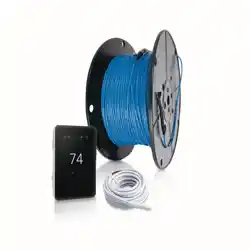
WarmWire
®
Please be aware local codes may require this product and/or the thermostatic control
to be installed or connected by an electrician.
2 of 36
Read this Manual BEFORE using this equipment.
Failure to read and follow all safety and use information can result
in death, serious personal injury, property damage, or damage
to the equipment.
Keep this Manual for future reference.
WarmWire
®
is a simple, economical way to warm any floor, and provide years of lasting comfort.
This instruction manual provides complete details, suggestions, and safety precautions for
installing this floor-warming system. Fasten the cables to the floor. Then, depending on the floor
coverings to be used, put down a layer of thin-set, thick-set, or self-leveling mortar on top of the
cables. Finally, install the floor coverings. It’s that simple!
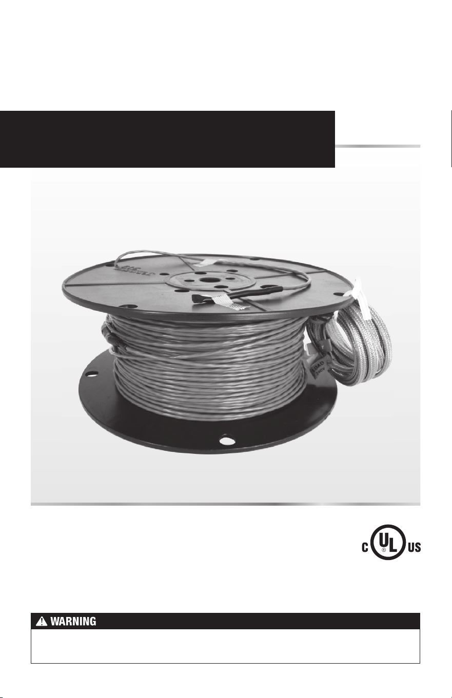
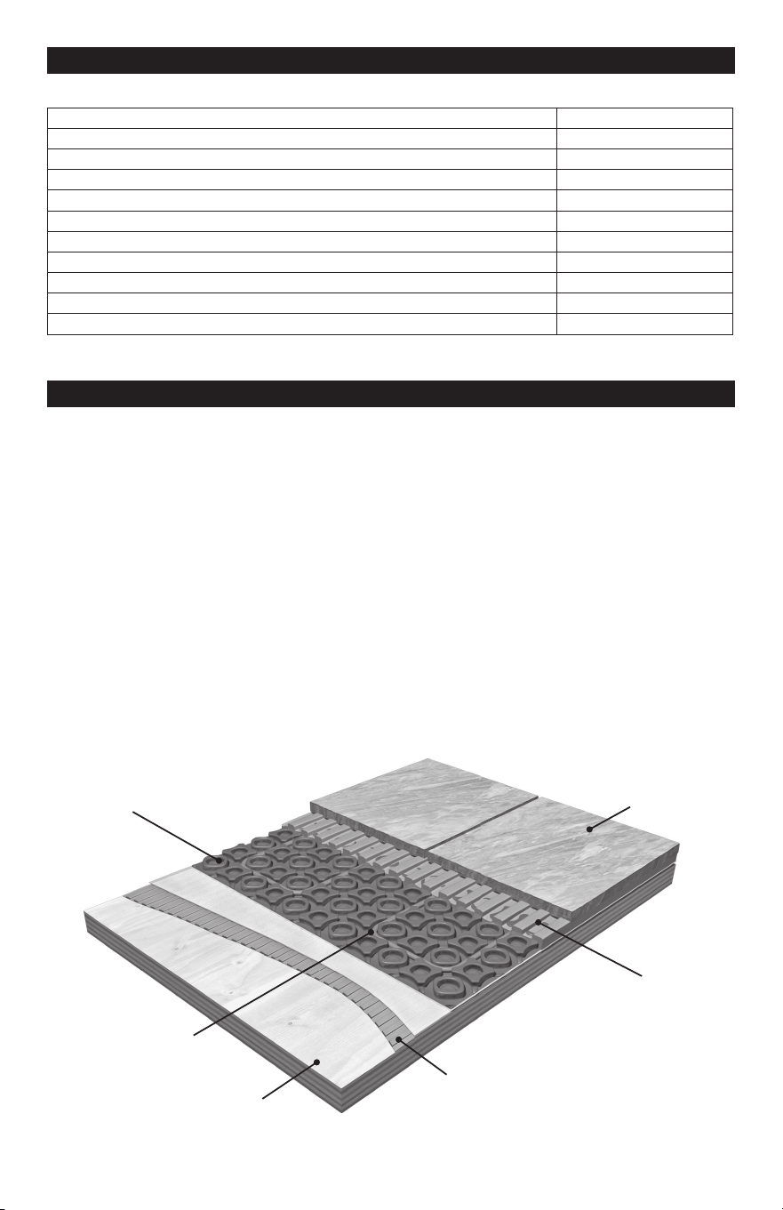
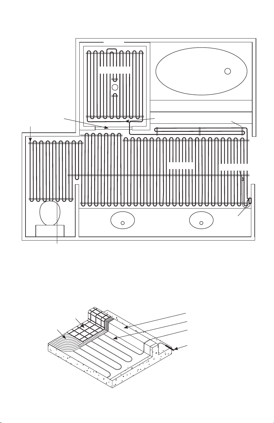
Heating
Wire
Factory
Splice
End Splice
Power Lead
Specifications for WarmWire:
WarmWire is a complete heating cable consisting of a series resistance heating cable and a
power lead for connection to the electric power supply. The heating cable cannot be cut to fit.
Voltages: 120 VAC, 240 VAC, 1-phase
Watts: 3 W/linear foot. Approximately 10.3 W/ft
2
(34 Btu/h/ft
2
) for 3.5" spacing, 12 W/ft
2
(41 Btu/h/ft
2
) for 3" spacing. and 14.4 W/ft
2
(51 Btu/h/ft
2
) for 2.5" spacing. (See Table 2)
2.5" spacing may only be used under masonry surfaces with a maximum floor covering R-value
of R-1.5 as indicated in this manual. 3" or 3.5" spacing may be used under floor covering types
with a maximum R-value of R-2.5.
Maximum circuit load: 15 amps
Maximum circuit overload protection: 20 amp breaker
GFCI: (Ground Fault Circuit Interrupter) required for each circuit (included in the SunStat control)
Listing: UL Listed for U.S. and Canada under UL 1673 and CAN/CSA C22.2 No. 130.2-93,
File No. E185866
Application: Indoor floor heating only (-X on the nameplate label indicates CUL Listing for this
application). Suitable for installation in a shower area (see pg 18 for restrictions) (-W on the
nameplate label indicates CUL Listing for Wet Location in Canada per Canadian Electrical
Code, Part I (CEC)).
Embedded in cement based
mortar only, polymer-modified
preferred (see Appendix 1).
Minimum bend radius: 1 inch
Maximum exposure temperature:
(continuous and storage) 194ºF (90ºC)
Minimum installation temperature: 50ºF (10ºC)
Installation must be performed by qualified persons, in accordance with local codes, ANSI/
NFPA 70 (NEC Article 424) and CEC Part 1 Section 62 where applicable. Prior to installation,
please consult the local codes in order to understand what is acceptable. To the extent this
information is not consistent with local codes, the local codes should be followed. However,
electrical wiring is required from a circuit breaker or other electrical circuit to the control.
It is recommended that an electrician perform these installation steps. Please be aware
local codes may require this product and/or the control to be installed by an electrician.
3 of 36
Important Safety Information
This is a safety-alert symbol. The safety alert symbol is shown alone or used
with a signal word (DANGER, WARNING, or CAUTION), a pictorial and/or a
safety message to identify hazards.
When you see this symbol alone or with a signal word on your equipment or in
this Manual, be alert to the potential for death or serious personal injury.
This pictorial alerts you to electricity, electrocution, and shock hazards.
This symbol identifies hazards which, if not avoided, could result in death
or serious injury.
This symbol identifies hazards which, if not avoided, could result in minor
or moderate injury.
This symbol identifies practices, actions, or failure to act which could
result in property damage or damage to the equipment.
Expected floor temperature
Heating performance is never guaranteed. The floor temperature attainable is dependent on
how well the floor is insulated, the temperature of the floor before start up, and the overall
thermal drain of the floor mass. Insulation is required for best performance. Refer to Phase
9 for important design considerations.
These are the three most common installations:
1.
Wood framing: With the cable installed on a well-insulated wood subfloor, and thin-set
mortar and tile on top, most floors can be heated up to 20°F warmer than they would
otherwise be.
2.
Insulated concrete slab: With the cables installed on an insulated concrete slab, and
thin-set mortar and tile on top, most floors can be heated up to perhaps 15°F warmer
than they would otherwise be.
3.
Uninsulated concrete slab: With the cables installed on an uninsulated concrete slab,
and thin-set mortar and tile on top, most floors can be heated up to perhaps 10°–15°F
warmer than they would otherwise be.
Please consult a designer or the factory if questions remain about the surface temperature
that can be expected from the cables in any particular construction. Please see “Phase 10:
Install Insulation” on page 22.
Table of Contents
Important Safety Information ..................... 3
1 - Preparations .........................................5
2 - Electrical Rough-in ...............................9
3 - HeatMatrix Cable Install ..................... 11
4 - CableStrap / Cable Install ..................14
5 - Shower Area Installation .....................18
6 - Final Steps ..........................................19
7 - Finish Wiring .......................................20
8 - Control Installation .............................21
9 - Install the Floor Coverings .................. 21
10 - Install Insulation ................................22
Appendices ..............................................23
Troubleshooting .......................................33
Warranty ................................................... 35
4 of 36
Table 1
As with any electrical product, care should be taken to guard against the
potential risk of fire, electric shock, and injury to persons. The following
cautions must be observed:
NEVER install WarmWire under carpet, wood, vinyl, or other non-masonry flooring without
embedding it in thin-set, thick-set, or self-leveling mortar.
NEVER install WarmWire in adhesives or glues intended for vinyl tile or other laminate flooring,
or in pre-mix mortars. It must be embedded in cement based mortar.
NEVER cut the heating wire. Doing so will cause dangerous overheating and will void the
warranty. The power lead may be cut shorter if necessary, but never remove completely from
the heating wire.
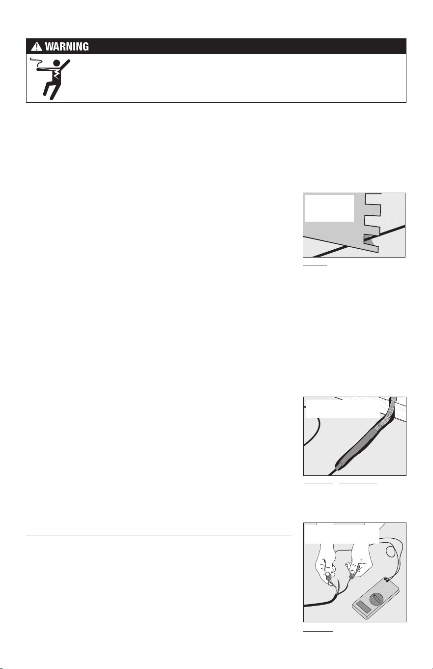
NEVER bang a trowel or other
tool on the heating cable.
NO!
ALWAYS completely embed
the factory splice and all heat-
ing wire in mortar. NEVER bend
the splice or place any part of it
in the wall or through the floor.
ALWAYS!
ALWAYS!
ALWAYS test the wire before
and after installation.
NEVER bang a trowel or other tool on the heating wire. Be careful
not to nick, cut, or pinch the wire causing it to be damaged.
NEVER use nails, staples, or similar to fasten the heating wire to
the floor.
NEVER attempt to repair a damaged heating wire, splice, or power
lead using unauthorized parts. Use only factory authorized repair
parts and methods.
NEVER remove the nameplate label from the power leads. Make
sure it is viewable for inspection later.
NEVER extend the heating wire beyond the room or area in which
it originates, under or through walls.
NEVER allow a power lead or sensor wire to cross over or under
a heating cable. Damage could result.
NEVER put the system into full operation until the tile or flooring
installer verifies all cement materials are fully cured (typically two
to four weeks).
NEVER energize WamWire while it is on the spool. Damage will result.
ALWAYS completely embed the heating wire and factory splices
in the floor mortar.
ALWAYS maintain a minimum of 2" spacing between heating wires.
ALWAYS pay close attention to voltage and amperage requirements
of the breaker, the thermostat, and the WarmWire. For instance,
do not supply 240 VAC power to 120 VAC WarmWire as damage
will result.
NEVER splice one heating wire to another heating wire to make it longer. Multiple WarmWire
power leads must be connected in parallel in a junction box or to the thermostat.
NEVER install one wire on top of another or overlap the heating wire on itself. This will cause
dangerous overheating.
NEVER forget to install the floor sensor included with the thermostat.
NEVER install WarmWire in any walls, or over walls or partitions that extend to the ceiling.
NEVER install wires under cabinets or other built-ins having no floor clearance, or in small closets.
Excessive heat will build up in these confined spaces, and the wire can be damaged by fasteners
(nails, screws, etc.) used to install built-ins.
5 of 36
Installation must be performed by qualified personnel, in accordance with local codes
and standards. A licensed electrician is recommended.
ALWAYS make sure all electrical work is done by qualified persons in accordance with local
building and electrical codes, Section 62 of the Canadian Electrical Code (CEC) Part I, and
the National Electrical Code (NEC), especially Article 424.
ALWAYS use copper only as supply conductors to the thermostat. Do not use aluminum.
ALWAYS seek help if a problem arises. If ever in doubt about the correct installation proce-
dure to follow, or if the product appears to be damaged, the factory must be called before
proceeding with the installation.
Before installing WarmWire, make sure to fully inspect the products and carefully plan the
site. All electrical components selected must be certified for use in your location.
Items Needed
Materials:
• WarmWire
®
system
• CableStrap
™
or HeatMatrix
™
crack-isolation membrane (purchased separately or as part
of a kit from SunTouch).
• SunStat
®
Thermostat with floor sensor (SunStat thermostats are UL Listed)
• SunStat Relay control if required (SunStat relays are UL Listed)
•
Control electrical box (UL Listed, extra deep, see control instructions for size and
type required)
• Junction electrical box (if required, must be UL Listed and proper size)
• Wire nuts (if required, must be UL Listed and proper size)
• Flexible or rigid conduit (if required, see Step 2.4, must be UL Listed and proper size)
• 12-guage or 14-guage electrical wiring cable (UL Listed, see Step 2.1)
• Nail plate
Tools:
•
Digital multi-meter (for ohms testing; must read up to 20,000 ohms (Ω) to measure sensor)
• Drill with
1
/
2
" and
3
/
4
" bits
• Hammer and chisel
• Hot glue gun and hot glue (craft grade)
• Wire strippers
• Phillips screwdriver
• Fish tape
• Hole saw
• Floor covering installation tools
Phase 1 - Preparations
Floor sensor is included
in the thermostat
packaging. This must
be installed in the floor
with the cable.

6 of 36
240 VAC
Model
Number
Total Sq. ft.
2.5" Spacing
14.4 watts/ft
2
Total Sq. ft.
3" Spacing
12 watts/ft
2
Total Sq. ft.
3.5" Spacing
10.3 watts/ft
2
Wire
Length
(ft.)
Amp
Draw
Resistance
(ohms)
240020 17 20 24 78 1.0 217 - 267
240030 25 30 36 117 1.5 143 - 176
240040 34 40 48 157 2.0 107 - 132
240050 42 50 60 196 2.5 84 - 104
240060 51 60 72 235 3.0 67 - 83
240070 59 70 84 274 3.5 59 - 73
240080 67 80 96 313 4.0 50 - 63
240090 76 90 108 352 4.5 45 - 56
240100 84 100 120 391 5.0 40 - 50
240120 101 120 144 470 6.0 33 - 42
240140 118 140 168 548 7.0 29 - 37
240160 135 160 192 626 8.0 24 - 31
240180 151 180 216 704 9.0 22 - 28
240200 168 200 240 783 10.0 20 - 26
Table 2 - Cable sizes (all Models with suffix WB & WR)
Please check the product label for exact ratings. This table is for reference only.
The coverage areas below are for CableStrap or HeatMatrix installation. Contact the factory
if using alternate attachment materials that may require different wire spacing. The area
coverages shown are approximate and may vary due to installation pattern variations. Also,
the heating cable is designed to operate 3 W/linear foot. Values for heat output per square
foot may vary depending on installation variations.
120 VAC
Model
Number
Total Sq. ft.
2.5" Spacing
14.4 watts/ft
2
Total Sq. ft.
3" Spacing
12 watts/ft
2
Total Sq. ft.
3.5" Spacing
10.3 watts/ft
2
Wire
Length
(ft.)
Amp
Draw
Resistance
(ohms)
120010 8 10 12 39 1.0 108 - 134
120015 13 15 18 59 1.5 72 - 89
120020 17 20 24 78 2.0 53 - 66
120025 21 25 30 98 2.5 42 - 52
120030 25 30 36 117 3.0 33 - 42
120035 29 35 42 137 3.5 29 - 37
120040 34 40 48 157 4.0 25 - 32
120045 38 45 54 176 4.5 22 - 28
120050 42 50 60 196 5.0 20 - 26
120060 51 60 72 235 6.0 16 - 21
120070 59 70 84 274 7.0 14 - 19
120080 67 80 96 313 8.0 12 - 16
120090 76 90 108 352 9.0 11 - 14
120100 84 100 120 391 10.0 10 - 13
It is important to select the proper size cable for the given area. WarmWire cannot be cut
shorter in order to fit a given area. Doing so will damage the heating wire and prevent the
system from working.
7 of 36
Ground
Lead
200 ohm setting
Black
Lead
White
or Blue
Lead
Black
Lead
White or
Blue Lead
Ground
Lead
Black
Lead
White or
Blue Lead
Ground
Lead
Temperature Typical Values
55°F (13°C) 17,000 ohms
65°F (18°C) 13,000 ohms
75°F (24°C) 10,000 ohms
85°F (29°C) 8,000 ohms
Table 3 - Floor Sensor
Resistance Values
STEP 1.1
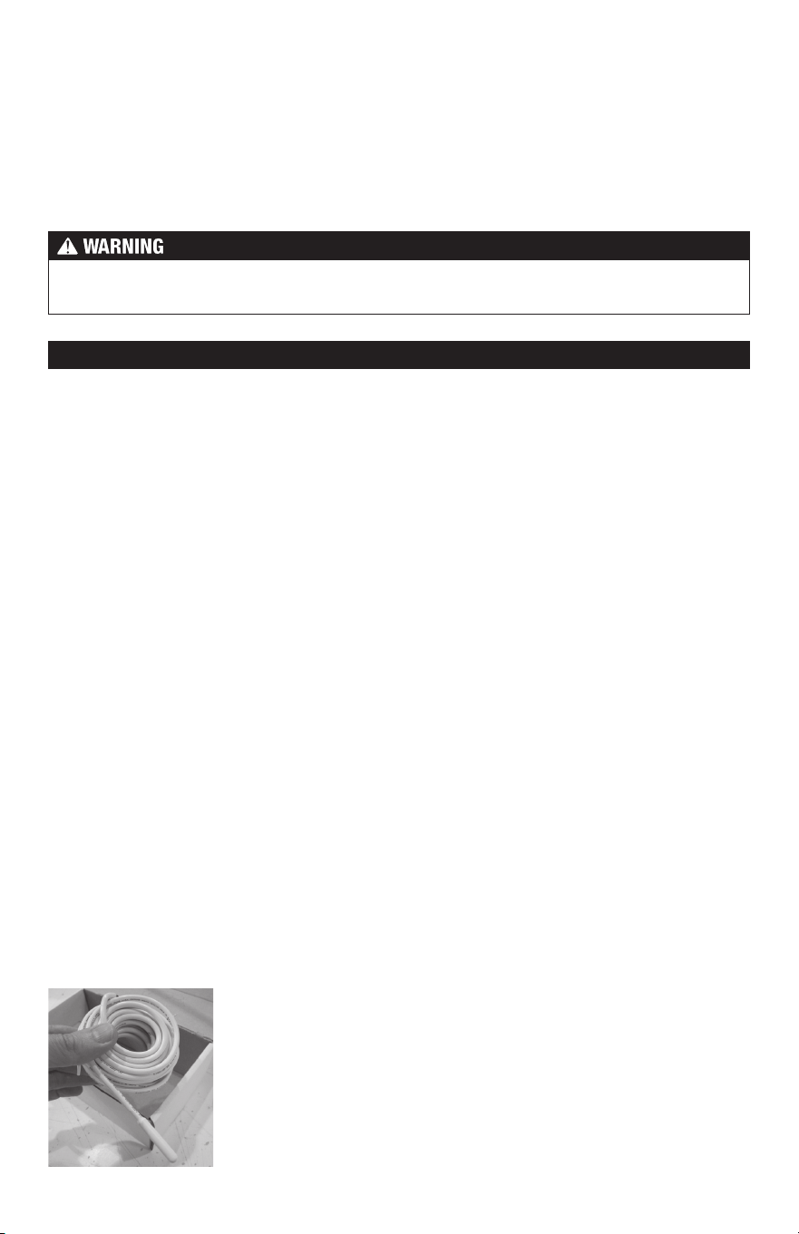
Remove the WarmWire, SunStat thermostat, and SunStat sensor from their packages. Inspect
them for any visible damage. Verify everything is the correct size and type according to the
plan and the order. Do not attempt to install a damaged product.
STEP 1.2
Record the product information. There is a factory-applied nameplate label on the power
leads. Do not remove this label. Record the cable serial number, model number, voltage,
and cable resistance range in the Cable and Sensor Resistance Log (Table 4). If installing
more than one cable, do this for each of them.
To prevent the risk of personal injury and/or death, make sure power is not
applied to the product until it is fully installed and ready for final testing. All
work must be done with power turned off to the circuit being worked on.
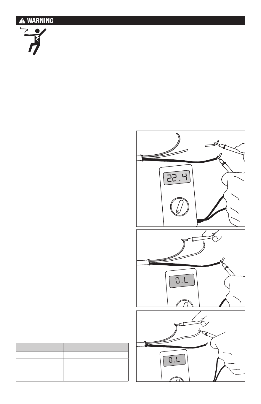
STEP 1.3
Use a digital multi-meter set to the 200Ω or 2000Ω
(2kΩ) range to measure the resistance between
the conductors of the cable power leads. Record
these resistances in Tab l e 4 under “Out of the
box before installation”. The resistance should
measure within the resistance range on the
nameplate label. If it is a little high or low, it may
be due to air temperatures or meter calibration.
Consult the factory if in doubt.
Measure the resistance between either of the
white or black leads and ground lead. This
measurement should be “open”, usually indicated
by an “OL” or a “I”. This is the same as displayed
when the test leads are not touching anything.
If there is any change in the reading, record
this information and contact the factory before
continuing. This could indicate damage, test
lead problems, or a number of other issues.
Try “pinning” the test leads to the cable lead
wires against a hard non-metal surface if the
readings continue to fluctuate.
Change the meter to the 20,000 ohms (20 kΩ) range.
Measure between the lead wires of the SunStat
sensor. This resistance varies according to the
temperature sensed. Table 3 provides approximate
resistance-to-temperature values for reference.
8 of 36
Cable 1 Cable 2 Cable 3
Cable serial number
Cable model
Cable voltage
Factory cable resistance range
OUT OF THE BOX BEFORE INSTALLATION (OHMS)
Cable black to white (black to blue for 240VAC)
Cable black to ground
Cable white to ground (blue to ground for 240VAC)
Sensor wire
AFTER CABLE AND SENSOR ARE FASTENED TO FLOOR (OHMS)
Cable black to white (black to blue for 240VAC)
Cable black to ground
Cable white to ground (blue to ground for 240VAC)
Sensor wire
AFTER FLOOR COVERINGS ARE INSTALLED (OHMS)
Cable black to white (black to blue for 240VAC)
Cable black to ground
Cable white to ground (blue to ground for 240VAC)
Sensor wire
Retain this log to retain the warranty! Do not discard!
Table 4 - Cable and Sensor Resistance Log
INSTALLATION NOTES
9 of 36
Phase 2 - Electrical Rough-in
To prevent the risk of personal injury and/or death, make sure power is not
applied to the product until it is fully installed and ready for final testing. All
work must be done with power turned off to the circuit being worked on.
STEP 2 .1:
Circuit Breaker (Overcurrent Protection)
WarmWire must be protected against overload by a circuit breaker. GFCI type (ground fault
circuit interrupter) or AFCI type (arc-fault circuit interrupter) breakers may be used if desired,
but are not necessary when using SunStat controls with integral GFCI.
The rating of the breaker (see Table 5) is determined by the amp draw of the heating cables.
Add the amp ratings of all cables to be connected to the SunStat control (see Table 2 or the
Nameplate Label on the cable). If the total is less than 12 amps, use a 15 or 20 Amp breaker
(preference is 15 A). If the total is between 12 and 15 amps, use a 20 Amp breaker. If the total
is over 15 A, another circuit will be required with its own breaker and SunStat control.
Circuit Breakers and Supply Wire
Cable(s) Supply Wire Breaker
VAC total amps (AWG)* qty type** rating
120 up to 12 amps 14 1 SP 15 or 20 A
120 up to 15 amps 12 1 SP 20 A
240 up to 12 amps 14 1 DP 15 or 20 A
240 up to 15 amps 12 1 DP 20 A
* Recommended only. Follow local codes for wire gauge size.
** SP= single-pole, DP=double-pole
Table 5
STEP 2.2:
Install Electrical Boxes
SunStat® Thermostat:
Install an extra-deep electrical box for the SunStat Thermostat. Follow the instructions
included with the thermostat for complete information on location and wiring.
SunStat Relay:
Install an extra-deep electrical box for any SunStat Relay(s). The SunStat Relay is used when
more than 15 amps must be controlled by one SunStat Thermostat. Follow the instructions
included with the SunStat Relay for complete information on location and wiring.
Junction Boxes:
If a cable is to be located so its power lead is not long enough to reach the SunStat thermostat
or SunStat Relay directly, a junction box must be installed. Do not attempt to make a connection
to other wiring without a junction box. Use a standard junction box with a cover, mounting
it below the subfloor, in the attic, in the wall, or in another location easily accessible after all
coverings are complete. If the SunStat sensor wire is not long enough to reach the SunStat
thermostat directly, it may be extended. A junction box may be required by local code to
make this connection. Follow the installation instructions included with the SunStat for details.
For construction with an existing wall or where the wall is covered, cut the necessary openings
to mount the electrical boxes listed above. Wait to install the boxes until all wiring is fed into
these locations to make it easier to pull the wire.
It may be possible to tap into an
existing circuit as long as there
is adequate capacity for the
cables(s) and any additional ap-
pliance, such as a hair dryer or
vacuum cleaner. Avoid circuits
which have lighting, motors,
exhaust fans, or hot tub pumps
due to possible interference.
Avoid shared neutrals.
10 of 36
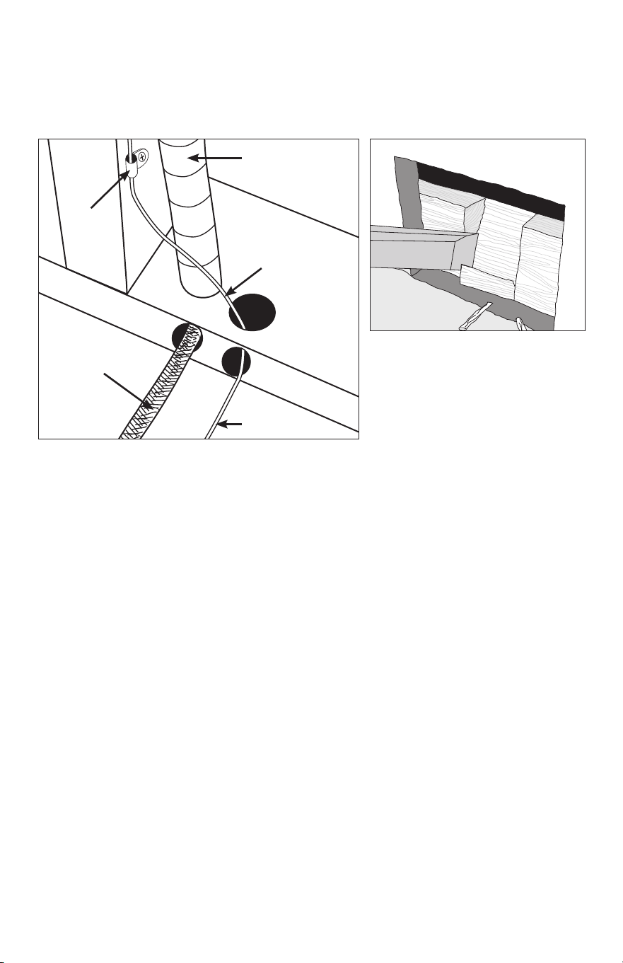
STEP 2.3:
Bottom Plate Work
Drill or chisel holes at the bottom plate as indicated. One hole is for routing the power lead
conduit and the other is for the thermostat sensor. These holes should be directly below
the electrical box(es).
Power lead
conduit
Wire Clip
Power lead
Sensor wire
Sensor wire
If going in to an existing wall, cut out dry
wall and chisel out bottom plate to route
wires to control.
STEP 2.4:
Install Power Lead Conduit and Thermostat Sensor
Power Lead Conduit:
The shielded power lead can be installed with or without electrical conduit (recommended
for added protection against nails or screws) depending on code requirements. Remove
one of the knock-outs in the electrical box to route the power lead. If electrical conduit is not
required by code, install a wire collar to secure the power leads where they enter the box.
If conduit is required by code, install
1
/
2
" (minimum) conduit from the bottom plate up to the
electrical box. For multiple power leads (multiple cables) install
3
/
4
" conduit.
SunStat Thermostat Sensor:
The SunStat sensor can be installed with or without electrical conduit depending on code
requirements. Conduit is recommended for added protection against nails or screws. Do not
place the sensor in the same conduit as the power leads to avoid possible interference. Open
a separate knock-out in the bottom of the thermostat box. Feed the sensor (and conduit,
if used) through the knock-out, down through the cut-out in the bottom plate, and out into
the floor where the heating cable will be installed. If the sensor wire needs to be secured
to the wall stud, wait until after the cable and sensor are completely installed on the floor.
STEP 2.5:
Rough-in Wiring:
Install appropriate 12 or 14 AWG electrical wire from the circuit breaker or branch circuit
source to the SunStat Thermostat electrical box (and SunStat Relay box(es) if needed)
following all codes, see Table 5.
If SunStat Relay(s) are used, feed appropriate wire (see SunStat Relay installation manual
for size and type) between the SunStat Relay(s) and the SunStat thermostat.
See SunStat Relay instructions for details of wire size and type.

11 of 36
STEP 3.1:
Determine the area for HeatMatrix
HeatMatrix is installed in both unheated and heated areas to provide crack-isolation and
waterproofing. Order a quantity that will cover the full square footage of the area to be tiled.
STEP 3.2:
Substrate preparation
The substrate must be flat, clean, dry, structurally sound, adequately load bearing and free
from material which may prevent bonding with the cement mortar.
STEP 3.3:
Cut lengths of HeatMatrix to fit the installation area
Measure and cut HeatMatrix to the required length for each row. Mark the boundary edge
on the subfloor to use as a guide for mortar application.
STEP 3.4:
Secure HeatMatrix to the substrate with mortar
The type of mortar used to secure the membrane to the subfloor depends on the type
of substrate. For most substrates, a premium modified thinset mortar is recommended.
Apply the mortar for the first row using a
1
/4" x
1
/4" notched trowel. Place the cut length of
HeatMatrix over the mortar. Position membrane, then readjust alignment if necessary by
lifting one end, and pulling lightly. Do not leave gaps between sections of HeatMatrix and
ensure the pattern is aligned. Work HeatMatrix in using a float or flat trowel. The entire
surface of the fleece on the underside of the membrane should be securely bonded to the
mortar. Observe the mortar open time while working. Trim out any rough drain openings or
other obstructions if necessary. Repeat the application process for each row until the space
to be tiled is completely covered.
STEP 3.5:
Outline the heated area
Mark the areas where the WarmWire cable will be installed. WarmWire should not be installed:
• Within 3" of the wall perimeter, door jamb, tub or shower base
• Within 6" of toilet flanges
• Under cabinets or fixtures that have no clearance under them
•
Within confined spaces like non walk-in closets or pantries where the heat cannot disperse,
particularly when objects are left on the floor.
Wire may be omitted from areas with no foot traffic. Refer to Appendix 1 for a table of
recommended clearances.
Phase 3 - Cable Installation with HeatMatrix
There are 2 installation methods for securing WarmWire:
•
HeatMatrix offers an easy way to install WarmWire while providing crack-isolation, vapor
management and waterproofing for installations with tile or stone. To install, WarmWire
is simply pressed into the HeatMatrix channels at a selected spacing. With HeatMatrix,
the space between rows can be easily adjusted to accommodate additional wire or
provide more or less heat in defined areas.
•
CableStrap is used for installations where crack-isolation and waterproofing are not
required, or in areas that need a lower profile. CableStrap be covered with a smooth
mortar finish for use under hardwood, laminate or resilient flooring. For CableStrap
installation instructions, refer to Phase 4.
12 of 36
STEP 3.6:
Make sure the cable fits
Check the cable size to ensure it will fit inside the Heated Area at the selected wire spacing
(see Table 2)
STEP 3.7:
Decide the cable layout
Decide which direction the cables will run on the floor for the easiest coverage. Refer to the
sample layouts in this manual for assistance. Depending on the shape of the area, it may
help to think of it in terms of several smaller areas.
If more than one heating cable is to be installed in the area, all Power Leads must come back
to the control or to a junction box and then to the control. Ensure there is sufficient space
to allow this when planning the wire layout.
STEP 3.8:
Position the Power Leads & Factory Splice
Carefully cut the tie binding the power lead coil. Do not nick the braid covering the power
lead. Locate the Factory Splice to ensure the power lead will reach the SunStat electrical
box or junction box location. It is acceptable to run the power leads several feet in the floor
area embedded in mortar if needed.
Draw an outline around the Factory Splice and move it aside. Cut a shallow channel in the
HeatMatrix to allow the Factory Splice to lay flat with the rest of the heating cable in the channel.
Pull the Power Leads up into the wall or conduit.
Add hot glue in the channel and set the Factory Splice and Power Lead in place.
The heating cable CANNOT be cut to fit. It must be kept its original length and fully
embedded in the mortar in the floor. Any modification or mis‐use of the heating cable will
void the warranty and cause potential shock or fire hazard.
NEVER run Power Leads across heating cables, under baseboard areas, or other potentially
damaging areas.
NEVER place heating cables closer than 2" from other heating cables.
NEVER place heating cables closer than 1" from Power Leads.
Completely embed the Factory Splice and heating cable in the floor mortar. Never bend
the factory splice. Never allow any part of the Factory Splice or heating cable to enter a
wall or cabinet or drop through the subfloor. Damage to the product will result.
STEP 3.9:
Install Cable
Press the heating cable into the HeatMatrix channels at the determined spacing. A hand
roller or grout float may be used to aid in installation.
13 of 36
= 14.8 W/ft
2
= 12.3 W/ft
2
3 33
3 32
= 10.6 W/ft
2
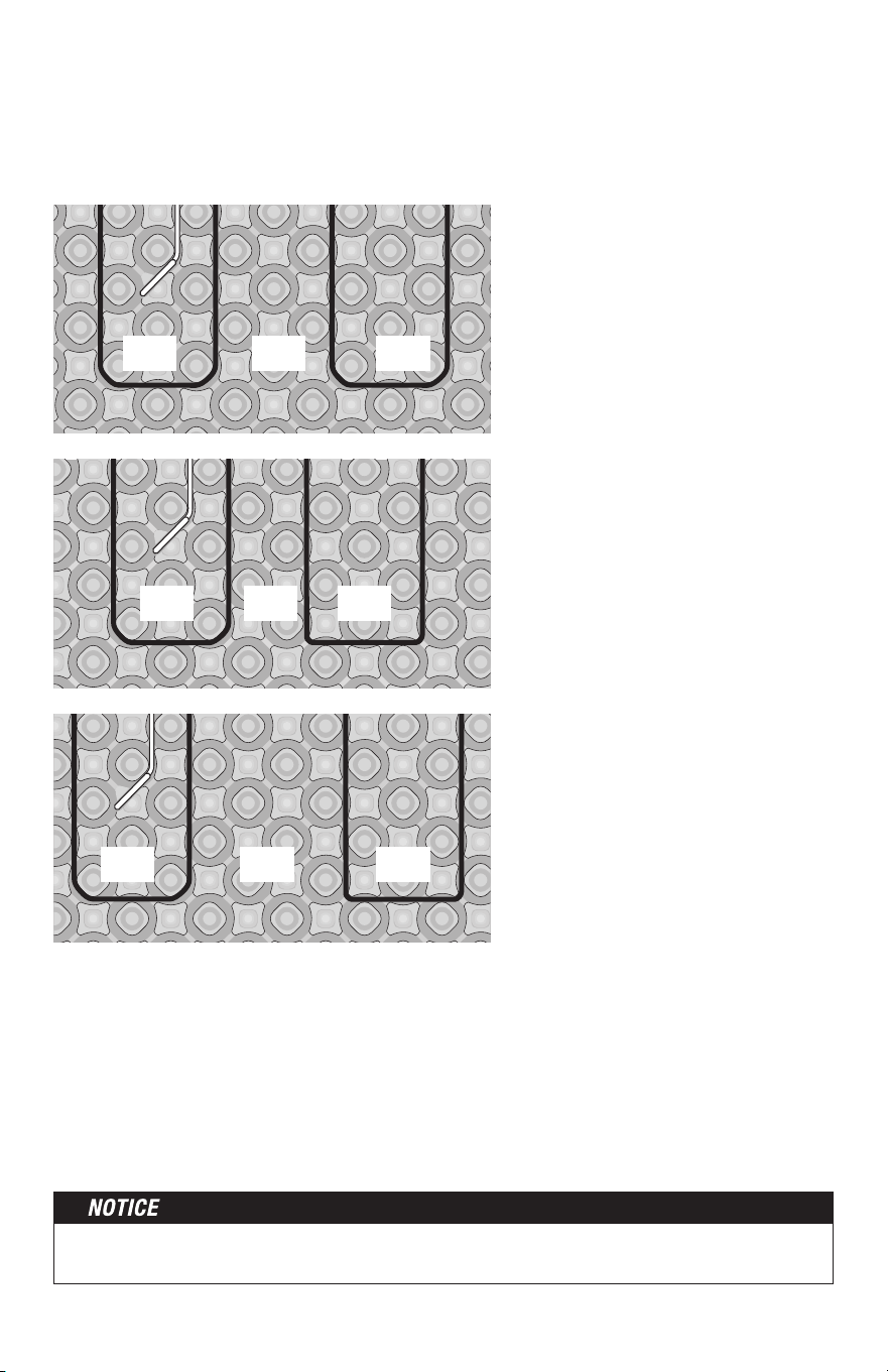
WarmWire spacing in HeatMatrix:
• Install WarmWire with 3-shapes in-between each row for approx. 12.3 W/ft
2
heat output
(standard spacing)
• Alternate between 3-shapes and 2 for a higher heat output of 14.8 W/ft
2
• Alternate between 3-shapes and 4 for a lower heat output of 10.6 W/ft
2
3 34
STEP 3.10
Bench seat
If covering a bench seat or step area (not in a shower area), place a single run of cable up
the riser. Use a section of HeatMatrix to secure the cable to the seat at the desired spacing,
then install a single run down the riser. Use an "s-shaped" curve to avoid sharp bends in
the cable at corners and help the cable to lay flat. The cable MUST be fully embedded in
mortar and have approved floor coverings. Use hot glue where necessary to secure the
cable flat against the riser.
NEVER space the cables less than 2" apart at any point, and never less than 2.5" average.
Never space more than 3.5" average.
14 of 36
STEP 4.1:
Floor Cleaning
The floor must be completely swept of all debris including all nails, dirt, wood, and other
construction debris. Make absolutely sure there are no objects on the floor which might
damage the wire.
Wet mop the floor at least twice to ensure there is no dirt or dust. This will allow proper
bonding of the mortar and proper stick of any adhesives or double-sided tape used later.
STEP 4.2:
Outline the Heated Area
Use a marker to outline the area where the heating cable will be installed. Refer to the
Appendix for a table of recommended clearances.
Cabinet vanities: Draw the border right up to the toe-kick. The wire can be installed up to
1" away from the vanity toe-kick.
Tubs and shower entries: Draw the border about 2" from the edge of the tub or shower.
Walls: Draw the border about 3" from the wall. If required to help the cable fit better, it may
be drawn 4" to 6" from the wall since people do not generally stand this close to a wall
anyway. It may also be drawn closer, but be careful that the cable will not be placed under
any trimwork.
Remember the heating cable length CANNOT be cut to fit. It must be kept its original
length and fully embedded in the mortar in the floor. Any modification or mis-use of the
heating cable will void the warranty and cause potential shock or fire hazard.
• Keep the cable at least 6" from toilet flanges
• Do not run the cable under cabinets or fixtures that have no clearance under them.
•
Avoid running the cable into a small closet or pantry. The heat cannot escape and things
can be laid on the floor, blocking the heat and potentially overheating and causing a
fire hazard.
STEP 4.3
Make Sure the Cable Fits
Check the cable size to ensure it will fit inside the Heated Area at the selected wire spacing.
See Table 2.
STEP 4.4
Decide the Layout
Decide which direction the cables will run on the floor for the easiest coverage. Refer to the
sample layouts in this manual for assistance. Depending on the shape of the area, it may
help to think of it in terms of several smaller areas.
Phase 4 - Cable Installation with CableStrap
™
15 of 36
Install CableStrap
STEP 4.5
Measure the edge of the Heated Area where
CableStrap will be installed.
Double-sided tape
STEP 4.6
Cut the CableStrap to length using
metal shears.
STEP 4.7
Secure the strap to the floor. Depending on
the floor type, different methods may be used.
Concrete, self-level, or similar: Double-
sided tape (if included with your cable), hot
glue, or strong spray adhesive may be used
if the floor is well cleaned and the strap is
wiped free of any oils. However, it is highly
recommended to also place screws at each
end of the strap, and every 4 to 5 feet, to
ensure it does not come loose. If using a
strong spray adhesive, apply to both the
back of the strap and the floor where it will
be placed, and carefully follow all spray
manufacturer’s instructions and
cautions.
Cut another piece of strap for the other end
of the area and secure to the floor.
Hot glue
Spray adhesive
OR
OR
OR
Plywood, cement board, or similar:
Galvanized nails or screws may be used to
secure the strap every 6" to 10".
Galvanized nails
Screws
16 of 36
Completely embed the Factory Splice and heating cable in the floor mortar. Never bend
the factory splice. Never allow any part of the Factory Splice or heating cable to enter a
wall or cabinet or drop through the subfloor. Damage to the product will result.
Position the Power
Leads & Factory Splice
STEP 4.8
Carefully cut the tie binding the power lead coil.
Do not nick the braid covering the power lead.
Locate the Factory Splice to ensure the power
lead will reach the SunStat electrical box or
junction box location. It is acceptable to run
the power leads several feet in the floor area
embedded in mortar if needed.
STEP 4.9
Draw an outline around the Factory Splice and
move it aside. Chisel a shallow channel to allow
the Factory Splice to lay flat with the rest of the
heating cable in the channel. Add hot glue in
the channel and set the Factory Splice in place.
3" spacing = 12 W/ft
2
2.5" spacing = 14.4 W/ft
2
3.5" spacing = 10.3 W/ft
2
Installing Cables on CableStrap
STEP 4.10
Weave the cable back and forth across the
area at the desired spacing until the other
side of the room has been reached. Once this
area is completed, press down all the tabs.
NEVER space the cables less than 2" apart
at any point, and never less than 2.5" average.
Never space more than 3.5" average.
STEP 4.11
If there are additional areas to cover with
cable, cut the lengths of strap necessary,
attach them to the floor, and begin weaving
the cable into that area.
Factory splice
17 of 36
STEP 4.17
Fill in with cable, adjusting spacing as necessary
to fill in as much of the area as possible.
Bench Seat
STEP 4.18
If covering a bench seat or step area (not in
a shower area), place a single run of cable
up the riser. Use CableStrap to secure the
cable to the seat area at the desired spacing,
then install a single run down the riser. Use
an "s-shaped" curve to avoid sharp bends
in the cable at corners and help the cable
to lay flat. Again, the cable on the riser and
seat area MUST be fully embedded in mortar
and have approved floor coverings. Use hot
glue where necessary to secure the cable
flat against the riser.
Corner shower or vanity
using CableStrap
STEP 4.14
For an angled area, such as a corner shower,
lay CableStrap at an angle and adjust tab
spacing to keep the wire spacing consistent.
Maintain a minimum of 3" distance between
the shower curb and wire.
Door entryway using CableStrap
STEP 4.16
For an entryway or other small area where
warmth is required, cut small sections of
strap to fit the ends of that area. Keep wire
3" away from the framing.
STEP 4.12
To secure long lengths of heating cable,
place additional, short lengths of the strap at
3–4-ft. intervals. Spray the back of the strap
with a high-tack adhesive, and slide the strap,
upside down, under the cables. Turn the strap
over when it is positioned and adhere to the
floor. Press the tabs down over the cables.
If a spray adhesive was not used, carefully
secure these short lengths of strap to the
floor without damaging the cable.
Install second cable
STEP
4.13
If a second cable is to be installed in the
area, all power leads must come back to
the control, or to a junction box and then to
the control. NEVER run power leads across
heating cables, under baseboard areas, or
other potentially damaging areas. Never join
two cables in series.
Other Installations
Because many different room shapes and floor
obstructions may be encountered in any given
installation, additional layouts are provided
below to assist in determining the best way to
complete installations in odd-shaped areas.
STEP 4.15
Fill in the section with cable. Make sure that
the cables are spaced evenly and parallel to
one another.
18 of 36
This application into a shower area must be verified by the local inspector or the authority
having jurisdiction (AHJ).
STEP 5.1
Cables only with (-W) on the nameplate label may be installed into a floor or bench seat
located in a shower area. It must never be installed into walls. In general, the cable should be
completely embedded into mortar as close to the surface coverings as possible. The cable
may be placed directly below the tile or stone coverings for the best performance by using
hot glue to secure the cable to the substrate.
If HeatMatrix or CableStraps are intended to be used instead, two methods may be used to
help avoid obstructing the flow of water to the drain when grout sealants begin to degrade:
(1) Place the HeatMatrix or CableStrap below the waterproofing system used, or (2) place a 3"
wide strip of HeatMatrix or CableStrap only around the perimeter of the shower floor and cover
above this with HeatMatrix Joint Strip or similar waterproofing and use hot glue everywhere
else to secure the cable.
See the Appendix for an example of this type installation.
Phase 5 - Shower Area Installation
Do not secure HeatMatrix or CableStrap with fasteners that may penetrate the
waterproofing membrane.
It is recommended that a dedicated cable be installed in the shower area separate from the
rest of the bath floor. In case there is ever a problem with the shower installation, this cable
could be disconnected without loss of heat to the rest of the floor.
STEP 5.2
Make sure the power lead factory splice (the connection between the power leads and the heating
cable) is located outside the shower area and at least 1' away from shower openings and other
similar areas normally exposed to water. Make sure the control is located at least 4' away from
shower openings such that it cannot be exposed to water or touched by a person in the shower area.
STEP 5.3
If the heating cable must enter the shower area over a curb, secure the cable at the edges
in an "s-shaped" curve to ensure the cable is not bent sharply or pinched when surface
coverings are installed. If the cable is installed below the waterproofing membrane, the curb
surface may be notched 1" wide and
1
/
8
" deep to help the cable lay flat, and coated with
mortar before applying the waterproofing. Do not damage any waterproofing components,
and do not run the heating cable through a non-masonry curb, causing it to overheat.
STEP 5.4
Fill in the floor area with cable. Around the drain leave at least 2" spacing from the edge of
the flange. Make sure cable is not placed where door hardware, handrails, or other items
may mount to the floor.
19 of 36
SunStat Thermostat
Factory Splice
Floor Sensor
WarmWire
Thin Set Mortar
Tile/Stone
A (-W) on the nameplate label
indicates a WarmWire cable
is approved for installation in
shower floors and/or benches.
STEP 5.5
If covering a bench seat in the shower with cable, secure it with hot glue or with HeatMatrix
or CableStrap located underneath waterproofing. Do not use fasteners that penetrate any
waterproofing membrane or waterproofing system. Use hot glue to secure a single run of
cable up the side of the bench riser. Fill in the seat area with cable. Then secure a single
run of cable down the riser if needed. Use an "s-shaped" curve to avoid sharp bends in the
cable at corners and help the cable to lay flat.
STEP 5.6
If the cable cannot exit the shower area, the end of the cable has a waterproof splice that
may be located in the shower area, fully embedded into the mortar like the heating cable.
STEP 5.7
If any part of the heating cable entering a shower area is damaged during installation, do
not attempt to repair it. A field repair or modification of the cable may result in serious
shock hazard.
Phase 6 - Final Steps
STEP 6.1
After the cable installation is completed, inspect the work. Make sure cable spacings are
correct and consistent, having no place where cables are less than 2" spacing, nor greater
than 4" spacing in the heated areas, no cables cross over each other, all the cables are
undamaged, and all areas to be heated are covered with cable.
STEP 6.2
Take resistance readings of the cable again to make sure it has not been damaged during
the installation. This is very important to do. Record these readings in the Cable and Sensor
Resistance Log (Table 4).
STEP 6.3
Lay cardboard, carpet, or similar material over the cables to protect them from damage until
the floor covering is installed.
20 of 36
Phase 7 - Finish Wiring
STEP 7.1
Feed the power leads from the cable up
through the hole drilled in the baseplate, or
up into the conduit to the control electrical
box (or junction box if one was used).
STEP 7. 2
Below the control, or wherever the floor sensor
is to be located, measure at least 1 ft. into
the heated area. Mark the spot where the
sensor will be attached to the floor. Be sure
to locate the sensor exactly between two of
the heating cables.
STEP 7.3
To make sure the sensor tip does not create
a high spot in the floor, it may be necessary
to chisel a channel into the floor and lay the
sensor tip into the channel. Hot glue the tip
into place.
STEP 7.4
Feed the sensor wire up to the control box.
Finish by securing a steel nail plate over the
wires to protect them against baseboard
nails later.
STEP 7.5
If it was necessary to end a power lead at a
junction box, feed 14- or 12-gauge electrical
wire from this box to the control box.
Tip: If more than one cable was installed,
label the ends of the power leads with a brief
description as to which area they supply power.
Use tape to label them “Cable 1,” “Cable 2,”
“Kitchen,” “Bath,” or similar. This will make
it easier to identify the leads later on. Take
photos of the installation. This will provide a
useful record for any future needs.
When using HeatMatrix, the sensor wire is
pressed into the channel between 2 wire
rows. For 3-shape spacing, the sensor is
placed at an angle with a small portion of
the membrane cut out to allow the sensor to
sit flush. For 4-shape spacing, the sensor is
positioned in the channel exactly between 2
wires. Do not install the sensor between wire
spaced 2-shapes apart.
3-shape spacing
4-shape spacing
21 of 36
Phase 8 - Control Installation
STEP 8.1:
If it has not already been done, install an electrical box for the SunStat
®
thermostat and
SunStat Relay. See Step 2.2 for details.
STEP 8.2
Read and follow the instructions included with the SunStat thermostat and SunStat Relay
for complete connection instructions, requirements, and mounting.
STEP 8.3
Make any final connections to the circuit breaker or branch circuit source.
Refer to the installation sheets provided with the controls for proper setting. The system
should now operate as designed.
Please leave this instruction manual, SunStat Control
instructions, and copies of photos of the installed heating system with the end user.
Most laminate and wood floor manufacturers specify their flooring should not be subjected to
temperatures over 82° to 84°F (27° to 28°C). Check with the flooring dealer or manufacturer
and set the thermostat Floor Limit temperature appropriately.
Make sure 120 VAC is supplied to 120 VAC cables and 240 VAC is supplied to 240 VAC
cables. Otherwise, dangerous overheating and possible fire hazard can result.
STEP 8.4
System Start Up
After all controls are installed, do not energize the system, except to briefly test operation
of all components (no longer than 10 minutes). Do not put the system into full operation
until the tile or flooring installer verifies all cement materials are fully cured (typically
two to four weeks). See mortar manufacturer’s instructions for recommended curing time.
Please note, this installation manual is not a structural or a floor covering installation manual
and is intended only for general guidance as it applies to the SunTouch WarmWire product.
It is recommended to consult with professional flooring installers to make sure proper
materials are used and proper installation techniques are followed.
Phase 9 - Floor Coverings / General Recommendations
When installing tile or stone, the Tile Council of North America (TCNA) guidelines or ANSI
specifications should be followed as a minimum standard.
A latex-modified thin-set cement-based mortar and grout is recommended instead of
water-based multi-purpose materials when installing a radiant product.

22 of 36
Do not use solvent based adhesives or pre-mix mortars because they are not as heat
resistant and do not conduct heat well.
•
When installing over HeatMatrix, read and follow the instructions given with the HeatMatrix
product. Apply the mortar by filling all voids in the HeatMatrix with the flat side of the
trowel, then comb to ensure 100% coverage. Avoid lining up tile grout lines with joints
between sections of HeatMatrix.
•
Select the proper size trowel for the installation of tile or stone. We recommend a minimum
3
/
8
" x
1
/
4
" trowel. This trowel works well for most ceramic tile. A thicker thin-set can be used
if required. Select the thin-set thickness in accordance with the floor covering requirements.
•
For additional information on tile installation, please contact TCNA at 864-646-8453 or
visit their web site at www.tileusa.com, or contact NTCA at 601-939-2071 or see their
web site at www.tile-assn.com.
•
When installing floor coverings other than tile or stone, follow industry and/or manufacturer’s
recommendations. Ensure the wire is first covered with a layer of self-leveling cement
based mortar, letting it cure fully before applying any surface underlayment, floating wood
or laminate flooring, carpet, etc.
•
With 3" or 3.5" spacing, the combined R-values of all floor coverings over the wire should
not exceed R-2.5. With 2.5" spacing, the combined R-value should not exceed R-1.5. Higher
R-values will diminish performance and trap too much heat. Consult the floor covering
manufacturer to verify compatibility with radiant electric heat.
• Make sure nails, screws, or other fasteners do not penetrate the floor in the heated area.
The wire can easily be damaged by fasteners penetrating the floor.
• All floor coverings must be in direct contact with the cement-based mortar encasing the
wire. Do not elevate the floor above the mortar mass.
•
Do not install 2" x 4" wooden nailers (sleepers) on top of a slab for the purpose of attaching
hardwood. Any air gap between the heating wire and the finished floor covering will
drastically reduce the overall output of the heated floor.
• Care should be taken when laying area rugs, throw rugs, and other surface products on
the floor. Most products are okay to use, but if in doubt, consult the product manufacturer
for compatibility. Do not use rubber backed products.
• When placing furniture make sure an air clearance of at least 1
1
/
2
" is available. Furniture
able to trap heat can damage the heating system, the flooring, and the furniture over time.
• After floor coverings have been installed, take resistance readings of the cable again to
make sure it has not been inadvertently damaged. Record these readings in the Cable
and Sensor Resistance Log (Table 4).
Phase 10 - Install Insulation
Insulate under the subfloor for better performance and efficiency of the system. Refer to the
Appendix for diagrams and insulation recommendations.
23 of 36
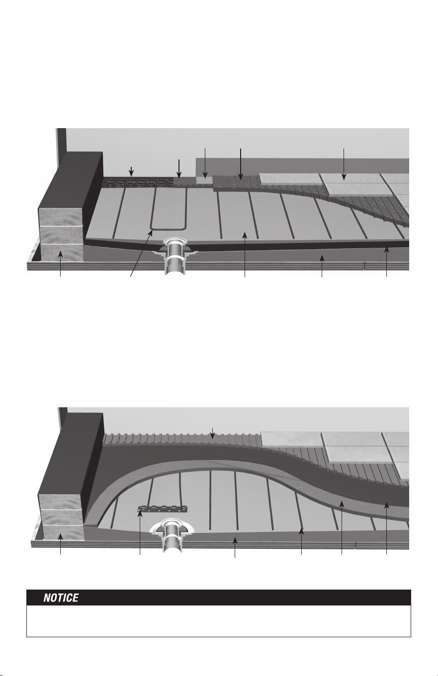
Types of Construction
Tile or stone applications with HeatMatrix
To install tile or stone over HeatMatrix and WarmWire, refer to the manufacturers recom-
mendations on mortar type, notch size and curing time. For areas exposed to surface water,
the seam between rows of HeatMatrix should be sealed with HeatMatrix Joint Strip. This is
done by troweling a strip of mortar over the seam, then pressing Joint Strip into the mortar.
Ensure these sections are as flush with the adjacent surfaces as possible. Once set, the tile
can be installed over these areas as usual.
Laminate, resilient or hardwood over HeatMatrix
When applying mortar over HeatMatrix in this application, the finish must be smooth instead
of notched. Do not use nails or screws to attach any type of flooring to the finished mortar
surface. A 'floating' floor installation is typically recommended for wood or laminate flooring
due to expansion and contraction caused by changes in floor temperature. When selecting
floor coverings, the R-value should not exceed R-2.5. when using 3" or 3.5" wire spacing
and not exceed R-1.5 when using 2.5" spacing.
Appendix 2: Types of Construction and Applications
Polymer modified
thinset mortar
Polymer modified
thin set mortar*
WarmWire
®
heating cable
Concrete or
plywood substrate
Tile, stone or
laminate flooring
HeatMatrix™
*modified or non-modified thin-set
mortar as recommended by
the tile manufacturer
Appendix 1: Minimum Clearances for WarmWire
Minimum Clearance
Bathroom vanity or kitchen cabinet toe-kick 1"
Showers or tub boundaries 2"
Doorway framing 3"
Walls 3"
Toilet flange 6"
Other heating wire 2"
Heating cable power lead 1"
Appliances (washer, dryer, oven) 1"
Baseboard heaters or radiators 3"
Below a built-in, cabinet, furniture 1"
Drains 2"
Do not install WarmWire in closets, pantries or in other small enclosed spaces.
24 of 36
Never bang a trowel on the Heating Wire to remove excess mortar from the trowel. This
could damage the heating wire.
Mortar Applications with CableStrap:
1.
If a backer board or plywood sheeting is used to strengthen the floor, or if the heating
wire will be placed directly onto the slab, install WarmWire in the thin-set mortar bond
coat above these materials.
2.
If a thicker mortar bed, or self-leveling concrete, is used to strengthen the floor, the
heating wire can be installed in either the mortar bed (dry-set) or in the mortar bond coat
directly below the tile or stone.
The heating wire is generally installed above the self-leveling mortar in a thin-set bond coat.
Use plastic lath instead of the typical metal lath when installing in a self-leveling layer.
Self-leveling mortar with CableStrap:
Self-leveling mortar may be used in CableStrap / WarmWire installations when the finished
surface needs to be smooth. This is applies to engineered wood, vinyl, laminate, or carpet
floor coverings. Attach the WarmWire to CableStrap on the subfloor or slab, then pour
self-leveling mortar
1
/
4
" to
1
/
2
" thick according to manufacturer’s specifications. Install floor
covering after the mortar has fully cured.
Special Precautions
Isolation Membrane: Install the heating wire above the membrane, whenever possible,
unless recommended otherwise by the membrane manufacturer.
Insulation: Insulation dramatically enhances the performance and efficiency of floor-warming
systems. Do not install rigid insulation directly above or below backer board or mortar.
Mosaic Tile: When installing mosaic tile, it is recommended to apply a two-step process.
First, embed the heating wire in a thin self-level mortar bed (
1
/
4
"–
3
/
8
"), then thin-set the mosaic
tile according to typical practice.
Expansion Joints: Do not install heating wires through an expansion joint. Install heating
wire right up to the joint, if necessary, but not through the joint.
Double-plywood over frame floor
Insulation
(per International Residential
Code, Chapter 11)
Latex-Portland cement
mortar bond coat
Heating cable
Plywood
Plywood subfloor
Tile/stone or laminate flooring
Joist
25 of 36
Insulation
(per International Residential
Code, Chapter 11)
Latex-Portland cement
mortar bond coat
Heating cable
Cement backerboard, thick-set, or
self-leveling mortar bed
Plywood subfloor
Tile/stone or laminate flooring
Joist
Insulation beneath slab
(per International Residential
Code, Chapter 11)
Heating cable
Concrete slab with rewire or rebar
Thin-set or self leveling
mortar bed
Tile/stone or laminate flooring
Antifracture membrane or cork
underlayment, as needed
Cement
backerboard over
frame floor
Thin-set over
slab on grade
26 of 36
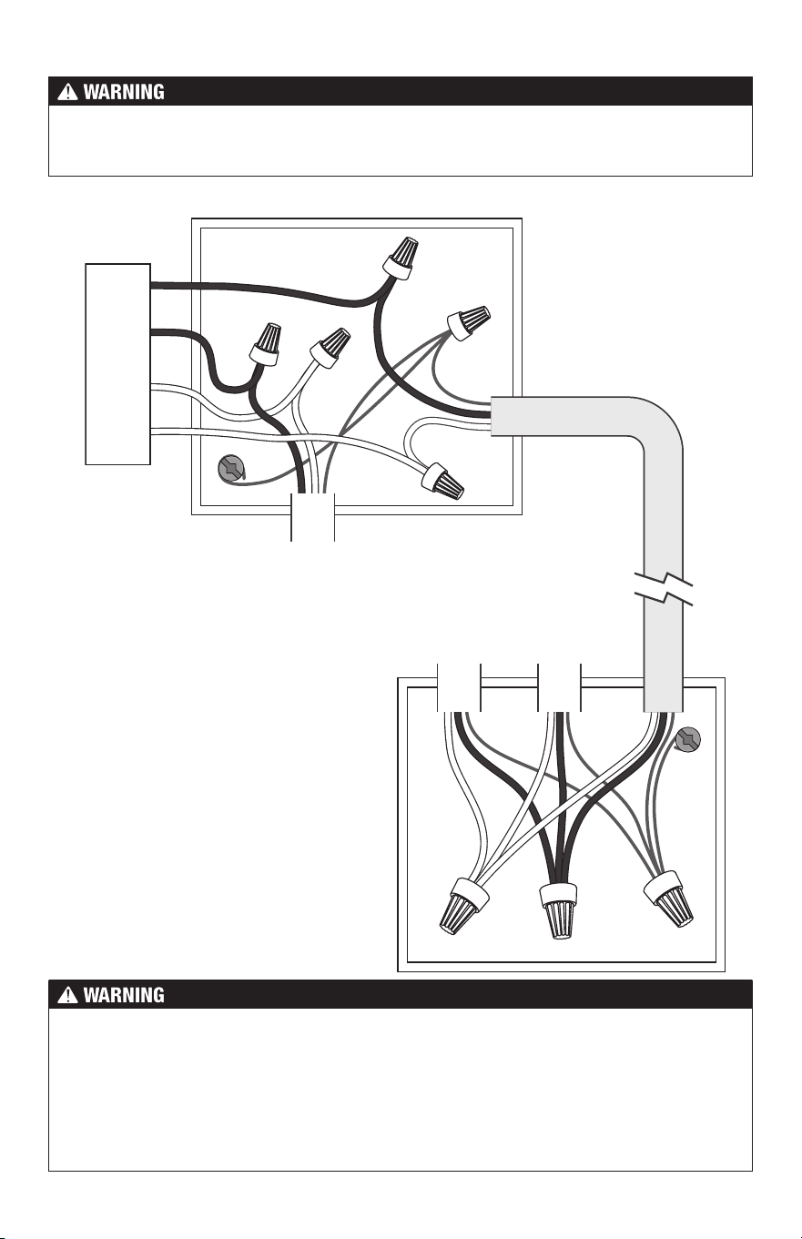
G
G
SunStat / Relay Connections
Load 1
Line 1
Line 2
Black
Black
White
White
Load 2
Connecting Multiple Cables
Multiple cables can be connected to a
single SunStat or SunStat Relay. Refer
to Table 2 and Table 5 for details on
calculating the maximum number of
cables per control or relay.
Power
Lead From
WarmWire
Cable 1
WarmWire
Connections
(Junction Box
Near Cables)
SunStat or Relay
Power Supply (120
VAC or 240 VAC)
Power
Lead From
WarmWire
Cable 2
Standard NM
Cable (12 or
14 AWG)
To prevent the risk of personal injury and/or death, do not perform any electrical work
unless qualified to do so. Work should be done with great care and with power turned off
to the circuit being worked on. Follow all local building and electrical codes.
The SunStat is not fully illustrated in these diagrams in order to simplify them. These
diagrams are given only as examples of how to properly connect multiple cables. Care
must be taken not to overfill a box. Be sure to use wire nuts that are the correct size for
the connections being made. Follow all codes for wiring.
All electrical work must be done by a qualified licensed electrician in accordance with local
building and electrical codes, and the National Electrical Code (NEC), especially Article
424 of the NEC, ANSI/NFPA70 and Section 62 of CEC Part 1.
27 of 36
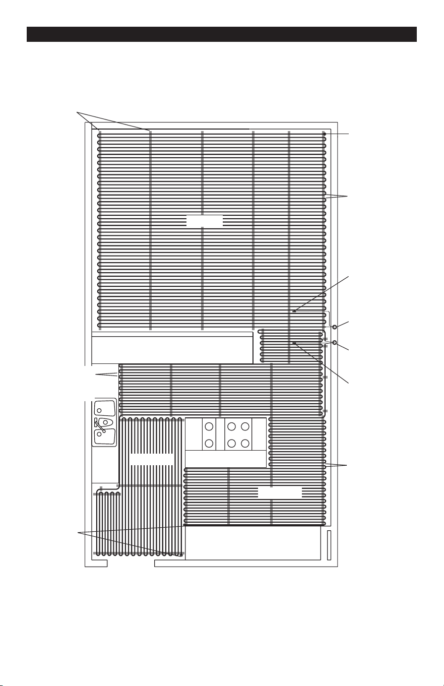
Appendix: Sample Layouts
Sink
Counter top and cabinetry
Counter top and cabinetry
Island
Zone 1a
Zone 1b
Zone 2
Zone 1
Control
Zone 2
Control
Zone 2
Sensor
Zone 1
Sensor
1 spool
70 ft
2
3" spacing
1 spool
240 ft
2
3.5" spacing
Cable end
Cable end
1 spool
120 ft
2
3" spacing
CableStrap
Kitchen and Family Room (normal heat loss, slab on grade with insulation)
Two zones, 240 volts: Three cables. 190 ft. of CableStrap, or eight 25-ft. rolls.
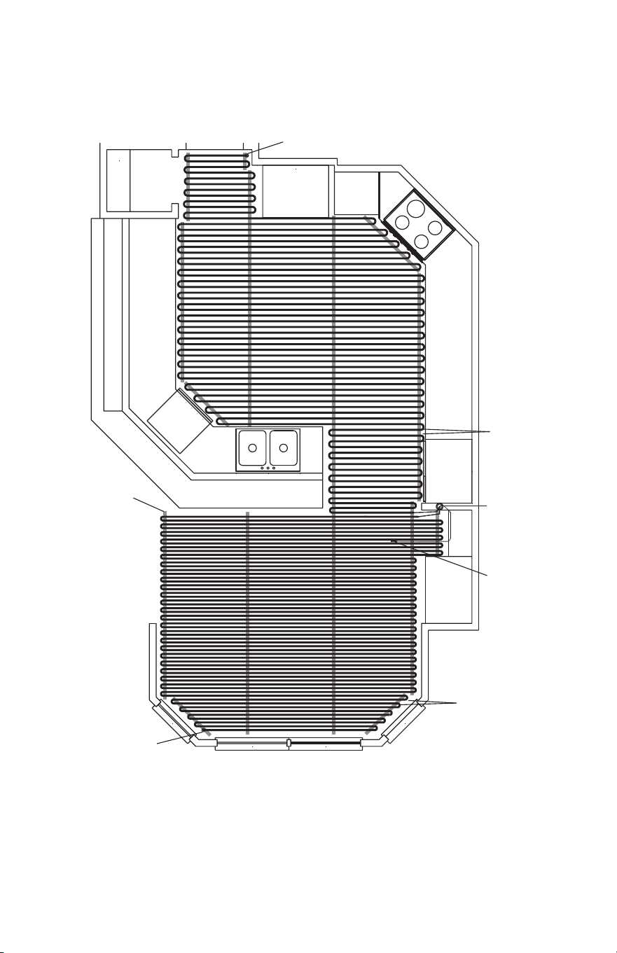
28 of 36
Control
Range
Counter/cabinetry
Counter and cabinetry
Pantry
Microwave
Floor
Sensor
Cable end
Cable end
1 spool
120 ft
2
3" spacing
1 spool
118 ft
2
2.5" spacing
CableStrap
Kitchen and SunRoom (normal and high heat loss, framed floor construction)
One zone, 240 volts: Two cables. 104 ft. of CableStrap, or five 25-ft. rolls.
29 of 36
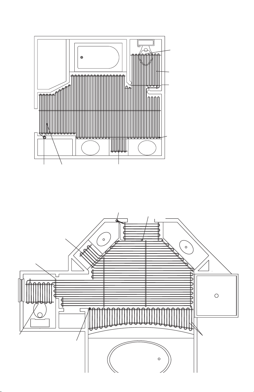
Master Bathroom (normal heat loss, framed floor construction)
One zone, 120 volts: One cable. 35 ft. of CableStrap, or two 25-ft. rolls.
Vanity Vanity
Toilet
Bath Tub
Cable end
Install cables
at least 6" away
from toilet flange
CableStrap
Control Floor Sensor
1 spool 100 ft
2
3" spacing
counter open to floor
Master Bathroom
(normal heat loss, framed floor construction)
One zone, 120 volts: One cable. 49 ft. of CableStrap, or two 25-ft. rolls.
Floor
Sensor
Vanity
Install cables
at least 6" away
from toilet flange
Bath Tub
Toilet
Closet
Cable end
CableStrap
counter open
to floor
Control
1 spool
90 ft
2
3" spacing
30 of 36
Basement Bathroom (high heat loss, below grade basement slab)
One zone, 120 volts: One cable. 39 ft. of CableStrap, or two 25-ft. rolls.
Vanity
Vanity
Bath Tub
Cable end
CableStrap
Floor
Sensor
Control
1 spool 59 ft
2
2.5" spacing
Closet
Shower
31 of 36
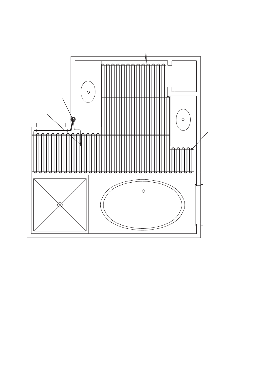
Master Bathroom (normal heat loss, framed floor construction)
Two zones, 120 volts: Two Cables
Vanity
Bath Tub
Shower
Toilet
Cable End
Cable End
Shower
Curb
Zone 1a
Zone 1b
Example of Cables only with (-W) on the nameplate label, where
cable is installed in a shower area and enters over the curb.
Install cables
at least 6" away
from toilet rings
Control
Floor Sensor
CableStrap
Shower Details
WarmWire
Factory Splice
Shower Curb
Tile
Thinset Mortar
Avoid sharp bends in cable
32 of 36
See phase 5 for complete details and Cautions. This application into a shower area must
be verified by the local inspector or the authority having jurisdiction.
Installing WarmWire above the waterproof liner
Installing WarmWire below the waterproof liner
WarmWire can be installed on a sloped mortar bed below the waterproof liner layer using
CableStrap or a 2-inch strip of HeatMatrix. Ensure the WarmWire and CableStrap or
HeatMatrix are fully covered in mortar, and trowel to provide a smooth finished surface. Apply
waterproof liner over the smoothed mortar surface according to the liner manufacturer's
instructions. Ensure the coverings above the waterproof liner do not exceed R-0.5 to avoid
capturing too much heat.
WarmWire can be installed above the waterproofing liner if the attachment method does
not puncture the liner. A overlay of thinset is first applied over the liner. CableStrap or
2-inch HeatMatrix strips are then attached to opposite sides of the shower using hot glue
or double sided tape. Leave a 2 inch gap between the drain flange and WarmWire. When
using HeatMatrix, strips are covered with mortar and Joint Tape after the wire is in place.
This reduces the chance of water becoming trapped in the low sections of the HeatMatrix
membrane. Ensure WarmWire is fully embedded within a cement based mortar before tiling.
Mortar bed sloped
towards drain
ThinsetWarmWire secured with hot
glue min. 2" from drain
Joint Strip Thinset
Thinset
HeatMatrix 2-
inch strip
Curb covered with
waterproofing
Waterproof
liner
Tile
Backer board
Mortar bed sloped
towards drain
WarmWire Cement
Mortar
CableStrap or
HeatMatrix strip
Curb covered with
waterproofing
Waterproof
liner
Thinset
Tile
Backer board
33 of 36
If not qualified to perform electrical installations, it is strongly recommended that a qualified,
licensed electrician be hired to install the heating cables and related electrical components.
If problems with the system arise, please consult the troubleshooting guide below.
Problem Possible Cause Solution
Cable resistance
measurement is
outside the range
printed on the
nameplate label.
An analog ohmmeter (using a
moving needle) was used to take
the reading.
Obtain a digital ohmmeter able to read 0 to 20,000
ohms and remeasure the resistance.
If measurement shows an open or
short circuit, the cable has been
damaged.
Record resistances between all wires and contact
the manufacturer.
If measurement is just a little low
or high, room temperature has
affected the resistance.
Make the room temperature 65°–75°F (18º-24ºC),
or contact the manufacturer.
The resistance measurement
could be from more than one
cable wired in series, or wired in
parallel. Either will provide false
resistance readings.
Make sure resistance measurements are for only
one cable at a time.
The multi-meter may be set to the
wrong scale.
The ohmmeter should typically be set to the 200
(200Ω) scale. For heating wire with resistance
range higher than 200 ohms on the nameplate
label, set the meter to the 2000 ohm (2kΩ) scale.
Floor does not
get warm.
Cable has been damaged.
Measure cable resistance. Check for both “open
circuit” and “short circuit” as detailed earlier in this
manual. If damaged, record resistances between all
wires and contact the manufacturer.
GFCI has tripped, indicated by a
light on the control or “GFCI TRIP”.
Check for loose wire connections. Reset the GFCI
on the control or circuit breaker. If it trips again,
check for a short circuit in the cable as detailed
earlier in this manual. If cable is damaged, record
resistances between all wires and contact the
manufacturer. If cable is not damaged, replace the
GFCI control. Also see “GFCI conflicts” below.
Incorrect voltage supplied,
or mismatched electrical
components used.
Measure “line” voltage, 120 VAC cables have black
and white leads. 240 VAC cables have black and
blue leads.
Uninsulated concrete slab floor.
Surface temperatures rise slowly on an uninsulated
slab and heat is lost to the ground below. If, after
5 to 8 hours of heating, the floor is not warmer to
the touch, check for cable damage (see “Cable has
been damaged” above). Measure “load” voltage/
amperage to cable.
Cables are wired in “series” or
“daisy chained” (end-to-end).
Multiple cables must be connected in “parallel” (or
black-to-black, white-to-white).
Troubleshooting Guide
Any electrical troubleshooting work should be performed with the power removed from
the circuit, unless otherwise noted.
34 of 36
Although this troubleshooting guide is provided to assist with problems experienced with
a floor-warming system, results are never guaranteed. The company does not assume any
liability or responsibility for damage or injury that may occur from using this guide.
If problems with the system persist, call the manufacturer.
Problem Possible Cause Solution
Floor heats
continuously.
Incorrect wiring. The control was
“bypassed” when it was wired to
the power supply.
Make sure wiring connections are correct. Consult
the wiring diagram on the back of the control, the
instructions that came with the control, or the
wiring diagrams in the Appendix.
Defective control. Return control to dealer for replacement.
Control is
not working
correctly.
If a programmable control, the
programming may be incorrect.
Carefully read and follow control
programming instructions.
Incorrect voltage supplied, or
mismatched components used.
Test voltage, verify parts. See “Incorrect voltage
supplied” section
Floor sensor is not wired properly,
or is not working properly.
Make sure only one floor sensor is connected
to the control.
Loose connection(s) on line side
and/or load side of control.
Remove and reinstall the wire nuts at each
connection. Make sure the wire nuts are tight.
Check all connections back to the breaker.
Defective control. Return control to dealer for replacement.
Control is not
working at all.
No power is supplied.
Check circuit breaker. Measure voltage at the
control. Check all connections between breaker
and control.
Floor sensor is not wired properly,
or is not working properly.
Make sure only one floor sensor is connected
to the control.
Defective control. Return control to dealer for replacement.
GFCI conflicts
and false-trips.
An electric motor or a ballasted
light source is sharing the circuit
with the cable(s).
Electric motors and similar electrical devices can
cause a GFCI to false-trip. Run a dedicated circuit
to the floor-warming system or select a different
branch circuit.
WARNING: This product contains chemicals known to the State of California to cause cancer and birth defects
or other reproductive harm. For more information: www.watts.com/prop65

35 of 36
Electric Floor-warming Products 25-year Limited Warranty
SunTouch and Watts Radiant (the Companies) warrant their respective
electric floor heating mats and cables (the Products) to be free
from defects in materials and workmanship for twenty-five (25)
years from the date of manufacture. Thermostats and controls
sold by the Companies are warranted, parts and materials, for
three (3) years from the date of purchase. The sole remedy for
controls is product replacement. This warranty is only provided to
customers who purchase the Products from authorized resellers,
and is transferable to subsequent owners of properties where
the Products are initially installed.
Under this Limited Warranty, the Companies will provide
the following:
If the Product is determined by the Companies to be defective
in materials and workmanship, and has not been damaged as a
result of abuse, misapplication or modification, the Companies
will refund all or part of the manufacturer’s published list price
of the Product at the time of purchase in accordance with the
following: 100% for the first ten (10) years, then prorated on a
diminishing 25-year scale for the remaining warranty period.
For example:
(1) Product found defective in the 5th year will receive the full
manufacturer’s published list price of the Product at the
time of purchase;
(2) Product found defective in the 15th year, with 10 years
remaining in the warranty period, will receive 10/25ths
of the manufacturer’s published list price of the Product
at the time of purchase.
In order to make a claim, you must:
(a) Provide the Company with sufficient details relating to
the nature of the defect, the installation, the history of
operation, and any repairs that may have been made.
(b) At the Company’s discretion and at the owner’s expense,
ship the Product to the Company or the Company’s local
representative or distributor.
(c) Provide proof that the Product was installed in accordance
with the applicable Product Installation Manual and any
special written design or installation guidelines by the
Companies for this project.
(d) Provide proof that the Product was installed in accordance
with the National Electrical Code (NEC) or the Canadian
Electrical Code (CEC), and all applicable local building and
electrical codes.
(e) Provide a retail sales receipt or proof of purchase.
The following are not covered by this Limited Warranty:
(a) Any incidental or consequential damage, including
inconvenience, loss of time or loss of income.
(b) Any labor or materials required to repair or replace the
Product or control, not authorized in writing by the Company.
(c) Any labor or materials required to remove, repair or replace
flooring materials.
(d) Any freight or delivery costs related to the Product, the
control, or any related flooring or electrical products.
The Companies assume no responsibility under this warranty for
any damage to the Product caused by any trades people, visitors
on the job site, or damage caused as a result of post-installation
work. The staff at the Company is available to answer any
questions regarding the proper installation or application of the
Product at this toll-free phone number: 800-276-2419. If you are
ever in doubt about the correct installation procedure to follow,
or if the Product appears to be damaged, you must call us before
proceeding with the installation, or proposed repair.
THE COMPANIES DISCLAIM ANY WARRANTY NOT PROVIDED HEREIN,
INCLUDING ANY IMPLIED WARRANTY OF MERCHANTABILITY OR
IMPLIED WARRANTY OF FITNESS FOR A PARTICULAR PURPOSE.
THE COMPANIES FURTHER DISCLAIM ANY RESPONSIBILITY
FOR SPECIAL, INDIRECT, SECONDARY, INCIDENTAL, OR
CONSEQUENTIAL DAMAGES ARISING FROM OWNERSHIP OR USE
OF THIS PRODUCT, INCLUDING INCONVENIENCE OR LOSS OF
USE. THERE ARE NO WARRANTIES WHICH EXTEND BEYOND THE
FACE OF THIS DOCUMENT. NO AGENT OR REPRESENTATIVE OF
THE COMPANIES HAS ANY AUTHORITY TO EXTEND OR MODIFY
THIS WARRANTY UNLESS SUCH EXTENSION OR MODIFICATION
IS MADE IN WRITING BY A CORPORATE OFFICER.
DUE TO DIFFERENCES IN BUILDING AND FLOOR INSULATION,
CLIMATE, AND FLOOR COVERINGS, THE COMPANIES MAKE
NO REPRESENTATION THAT THE FLOOR TEMPERATURE WILL
ACHIEVE ANY PARTICULAR TEMPERATURE, OR TEMPERATURE
RISE. UL® STANDARD LISTING REQUIREMENTS LIMIT THE HEAT
OUTPUT OF REGULAR MATS AND CABLES TO 15 WATTS PER
SQUARE FOOT DEPENDING ON CABLE INSTALL SPACING, AND
UNDERFLOOR MATS TO 10 WATTS PER SQUARE FOOT, AND AS
SUCH, USERS MAY OR MAY NOT BE SATISFIED WITH THE FLOOR
WARMTH THAT IS PRODUCED. THE COMPANIES DO WARRANT
THAT ALL PRODUCTS WILL PRODUCE THE RATED OUTPUT
LISTED ON THE PRODUCT NAMEPLATE, WHEN OPERATED AT
THE RATED VOLTAGE.
Some states do not allow the exclusion or limitation of incidental or
consequential damages and some states do not allow limitations
on how long implied warranties may last. Therefore, the above
limitations or exclusions may not apply to you. This warranty
gives you specific legal rights and you may also have other rights,
which vary from state to state. SO FAR AS IS CONSISTENT WITH
APPLICABLE STATE LAW, ANY IMPLIED WARRANTIES THAT MAY
NOT BE DISCLAIMED, INCLUDING IMPLIED WARRANTIES OF
MERCHANTABILITY OR FITNESS FOR A PARTICULAR PURPOSE
ARE LIMITED IN DURATION TO TWENTY-FIVE YEARS FROM THE
DATE OF MANUFACTURE.
Terms and Conditions
Shipping Discrepancies: Incoming materials should be inventoried
for completeness and for possible shipping damage. Any visible
damages or shortages must be noted prior to accepting the
material. Once the receiving personnel accept the material on their
dock, they have relieved the freight company of any responsibility.
Any discrepancy concerning type or quantity of material shipped,
must be brought to the attention of the Companies within 15 days
of the shipping date entered on the packing slip for the order.
Return Policy: The Companies items may be returned within
one year from the date of purchase, if they are not damaged or
used. There will be a 15% restock charge applied to items returned
due to overstock or customer order error. All returned items must
be in new condition. Products, controls or other parts that have a
quality defect will be replaced (not credited) at no charge to the
customer. If an item is shipped in error, there will be no restocking
charge. All items returned, for replacement, credit or repair, must
have a Returned Goods Authorization (RGA) number, or they will
not be accepted. Please call our order desk for an RGA number.
Products older than one year are excluded from these terms and
conditions and may not be returned. No returns will be accepted
for the Custom TapeMat product.
Products that have been damaged, or Products that have been cut,
may not be returned. This includes Products that have had mortar
or concrete materials applied to them. These Products cannot be
repaired and cannot be resold; therefore, we cannot accept them.
Effective: APRIL 1, 2006. This warranty applies to all Products
purchased after this date.

IOM-WR-WW 2129 EDP#81017514 ©2021Watts
Affiliations:
The SunTouch and Watts Radiant
manufacturing facility’s Quality
System is an ISO 9001:2008
registered facility through LRQA.
8
4 0 2 1 3 1 9 7 9 0
2
SunTouch Customer Support
USA Toll-free: (888) 432-8932
Canada Toll-free: (888) 208-8927
Latin America Tel: (52) 81-1001-8600
SunTouch.com
Watts Radiant Customer Support
USA Toll-free: (800) 276-2419
Watts.com
Canada Toll-free: (888) 208-8927
Watts.ca
