EN
AE BH DZ
INSTRUCTIONS FOR USE
FREE STANDING COOKER
EG IQ JO KW
LB LY MA OM QA SA TN
1
We thank you for your trust and the purchase of our appliance.
This detailed instruction manual is supplied to make the use of this product easier. The instructions should allow you
to learn about your new appliance as quickly as possible.
Make sure you have received an undamaged appliance. If you do find transport damage, please contact the seller from
which you purchased the appliance, or the regional warehouse from which it was supplied.
These instructions are only valid if the country symbol is printed on the appliance. If there is NO country symbol on the
appliance, please consult the technical instructions for adjusting the appliance according to the requirements for use
in the relevant country.
The appliance has to be connected in compliance with the effective regulations, and it may only be used in well
ventilated areas. Read the instructions before connecting or using the appliance.
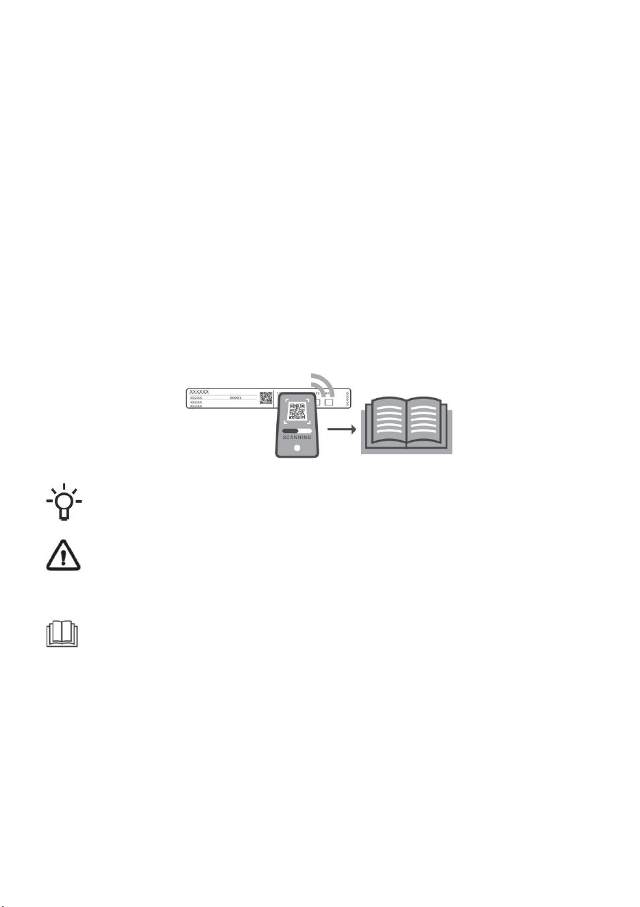
For more detailed instructions and tips, please visit http://www.gorenje.com or scan the QR code on the rating
plate.
The following symbols are used throughout the manual and they have the following meanings:
INFORMATION!
Information, advice, tip, or recommendation
WARNING!
Warning – general danger
It is important that you carefully read the instructions.

2
IMPORTANT SAFETY INSTRUCTIONS
CAREFULLY READ THE INSTRUCTIONS AND SAVE
THEM FOR FUTURE REFERENCE.
This appliance may only be used by children aged 8 years and above and persons with
reduced physical, sensory or mental capabilities or lack of experience and knowledge if
supervision or instructions are provided to them concerning use of the appliance in a safe
way and if they understand the hazards involved. Do not let the children play with the
appliance. Cleaning and user maintenance shall not be made by children without
supervision.
WARNING: The appliance and some of its accessible parts may become very hot during
use. Be careful not to touch the heating parts of the appliance. Children younger than 8
years of age shall be kept away unless continuously supervised.
WARNING: The accessible parts of the appliance may become hot during use. Young
children should be kept away from the oven.
WARNING: Danger of fire: do not store items on the cooking surfaces.
CAUTION: The cooking process and a short term cooking process has to be supervised
continuously.
WARNING: Unattended cooking on a hob with fat or oil can be dangerous and may result in
fire. NEVER try to extinguish a fire with water, but switch off the appliance and then cover
flame e.g. with a lid or a proof blanket.
WARNING: Before replacing the light bulb, make sure the appliance has been disconnected
from the mains power, in order to prevent the hazard of an electric shock.
Appliance must not be installed behind a decorative door in order to avoid overheating.
WARNING: If the surface is cracked, switch off the appliance to avoid the possibility of
electric shock.
Do not use harsh abrasive cleaners or sharp metal scrapers to clean the oven door glass,
since they can scratch the surface, which may result in shattering of the glass.
Do not use steam cleaners or high-pressure cleaners to clean the appliance, as this may
result in an electric shock.
The appliance is not intended to be controlled by external timers or separate remote control
system.
WARNING: Use only hob guards designed by the manufacturer of the cooking appliance or
indicated by the manufacturer of the appliance in the instructions for use as suitable or hob
guards incorporated in the appliance. The use of inappropriate guards can cause accidents.
The appliance is intended to be placed directly on the floor, without any supports or plinths.
3
Make sure the lid is clean and that there is no liquid spilt on it before raising it. It may only
be closed when the cooking zones have completely cooled down.
If the supply cord is damaged, it must be replaced by the manufacturer, its service agent or
similarly qualified persons in order to avoid a hazard.
CAUTION: This appliance is for cooking purposes only. It must not be used for other
purposes, for example room heating.
Cooker with stainless steel control panel and electrical oven is equipped with a cooling fan.
During operation of the oven, air flows from the cooker in the area under the control panel
when door is closed. If there is no air flow switch off the appliance and contact service.
The appliance may only be connected to the mains power by an authorized service
technician or expert. Clamps (instead of connecting cable) should be protected by a clamp
cover (see additional equipment). Tampering with the appliance or non-professional repair
thereof may result in risk of severe injury or damage to the product.
Unauthorized service and repair can result in risk of explosion, electric shock, or short circuit
and consequently personal injury and damage to the appliance.Such tasks may only be
carried out by an authorized expert.
Prior to installation, ensure that the local distribution conditions (nature of the gas and gas
pressure) and the adjustment of the appliance are compatible.
The adjustment conditions for this appliance are stated on the label (or data plate).
This appliance is not connected to a combustion products evacuation device. It shall be
installed and connected in accordance with current installation regulations. Particular
attention shall be given to the relevant requirements regarding ventilation.
CAUTION: The use of a gas cooking appliance results in the production of heat, moisture
and products of combustion in the room in which it is installed. Ensure that the kitchen is well
ventilated especially when the appliance is in use: keep natural ventilation holes open or
install a mechanical ventilation device (mechanical extractor hood).
Prolonged intensive use of the appliance may require additional ventilation, for example the
increasing of mechanical ventilation where present, additional ventilation to safely remove
the products of combustion to outside (external) air whilst also providing room air changes
with additional ventilation. Consult a professional before installation of the additional
ventilation.
CAUTION: possibility of tilting.

4
WARNING: In order to prevent tipping of the appliance,
stabilising means must be installed. Refer to the
instructions for installation.
This is a class 1 and 2/1 appliance. The appliance may touch the adjacent cabinets on both
sides when placed in a row. On one side, a tall cabinet – taller than the appliance – may be
placed at a distance of at least 10 cm from the appliance. On the other side, only a cabinet
of the same height may be placed.
Pay attention to correct placement of the burner parts.
Do not install the appliance near powerful sources of heat, such as solid fuel stoves, because
high temperature near them can damage the appliance.
Close the main inlet valve if you do not intend to use the burners for a longer period of time
(e.g. before going on vacation).
If the power cords of other appliances located near this appliance are caught in the oven
door, they may be damaged, which may in turn result in a short circuit. Therefore, keep the
power cords of other appliances at a safe distance.
If you observe any faults on the gas installation or smell gas in the room:
• immediately shut off the gas supply or close the gas cylinder;
• put out any open fire and extinguish any tobacco product;
• do not switch any electrical appliance on or off (including lights);
• thoroughly ventilate the room – open the windows;
• immediately inform the service centre or an authorized natural gas distributor.
Do not line the oven walls with aluminium foil and do not place baking trays or other cookware
on the oven bottom. Aluminium foil would prevent air circulation in the oven, hinder the
cooking process, and ruin the enamel coating.
Oven door become very hot during operation. A third glass is installed for extra protection,
reducing the temperature of the outside surface (only with some models).
Oven door hinges may be damaged when under excessive load. Do not place heavy pans
on open oven door and do not lean against open oven door when cleaning the oven cavity.
Never stand on the open oven door and do not let children sit on it.
An additional protective means to avoid contact with the oven door is available. This part
shall be fitted when young children are likely to be present.
Make sure the vents are never covered or obstructed in any other way.

5
In case of cooling fan failure, please stop using the appliance, switch it off and call a service
technician.
NOTICE In case the appliance is equipped with a glass or glass ceramic cooking surface. In
case of breakage:
• Immediately close the input of fuel into the burners and disconnect the electric heating
elements and the appliance from the mains.
• Do not touch the surface of appliance.
• Do not use the appliance.
For appliance connection use a 3x1,5 mm
2
cord with mark H05VV-F3G1,5 or better. Cord
must be installed by service agent or similary quialified person.
Appliance must be connected to fixed wiring which is in accordance with the witing rules.
Appliance must be connected to fixed wiring which has incorporated means of disconnection.
Fixed wiring must be made in accordance with the wiring rules.
BEFORE CONNECTING THE APPLIANCE
Carefully read the instructions for use before connecting the appliance. Repair or any
warranty claim resulting from incorrect connection or use of the appliance shall not
be covered by the warranty.
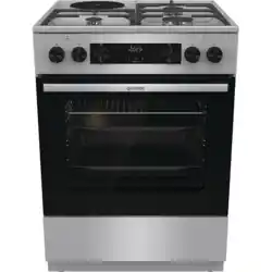
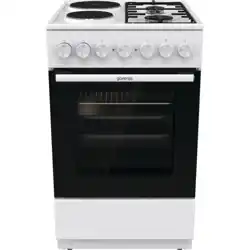
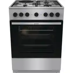
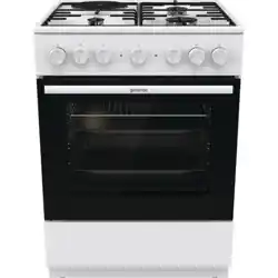
6
FREE STANDING COOKER
Appliance description
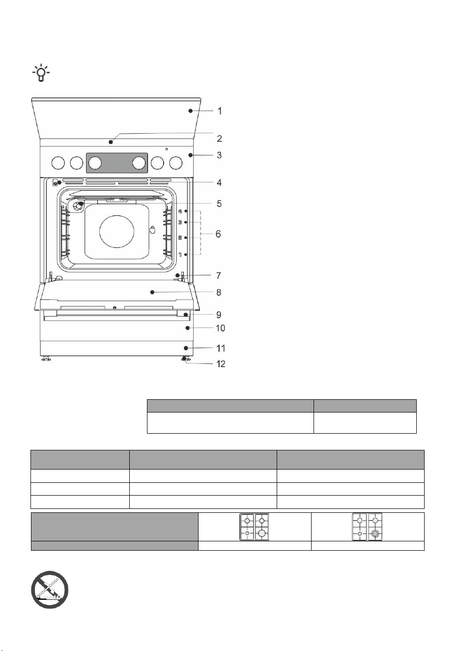
INFORMATION!
Appliance functions and equipment depend on the model.
1 lid
2 cooking hob
3 control unit
4 door switch
5 lighting
6 guides – cooking levels
7 rating plate
8 oven door
9 door handle
10 drawer/flip down
11 plinth
12 adjustable feets
Electrical parameters (depending on the model, see appliance data plate)
220-240V 1N~; 50/60 Hz, 1x16A
Degree of protection: IPX0
HEAT INPUT
Type designation
Total nominal electric input (kW)
(Oven without grill)
Total nominal electric input (kW)
(Oven with grill)
FM6A1x-xxxxx
2,2
2,8
FM6A3x-xxxxx
3,2
2,8
FM6A4x-xxxxx
-
3,3
Cooking hob
Total nominal gas heat input (kW)
7,8
8,4
APPLIANCE LID
Make sure the lid is clean and that there is no liquid spilt on it before raising it. It may only be closed
when the cooking zones have completely cooled down.
Do not close the lid when the burner is lit!
Turn off all the burners before shutting the lid.
Country of destination
Appliance Categories
AE, BH, IQ, JO, KW, OM, QA, SA, DZ, EG, LB,
LY, MC, TN
II2H3B/P
7
APPLIANCE DRAWER
Do not store combustible, explosive, volatile or temperature-sensitive items (such as paper, dish cloths,
plastic bags, cleaners or detergents and spray cans) in the oven's storage drawer, as they can ignite during
over operation and cause a fire.
WIRE GUIDES
The wire guides allow preparation of the food on four levels (please note that the levels/ guides are counted from the
bottom up). Guides 3 and 4 are intended for grilling.
Appliance operation is safe with and without tray guides.
TELESCOPIC PULL-OUT GUIDES
Telescopic pull-out guides may be fitted for the 2nd, 3rd, and 4th level. Pull-out guides can be partly or fully extendible.
EMBOSSED
The oven has stamped side grooves in four levels for inserting of the grid and baking sheets.
OVEN DOOR SWITCH
The switch deactivates oven heating and the fan when the oven door is opened during the cooking process. When the
door is closed, the switch turns the heaters back on.
COOLING FAN
The appliance is fitted with a cooling fan that cools the housing and the appliance control panel.
The cooling fan is in operation when the oven is in operation.
The appliance and some of the accessible parts tend to heat up during cooking. Use oven mitts.
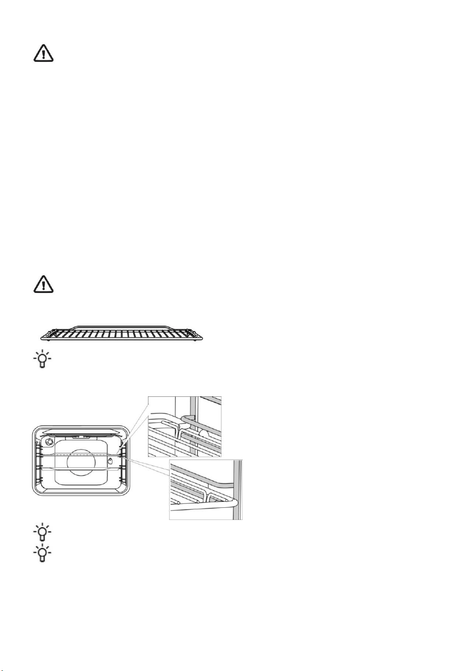
GRID
There is a safety latch on the grid. Therefore, lift the grid slightly at the front when pulling it out from the oven.
The grid or the tray should always be inserted into the groove between the two wire profiles.
With telescopic extendible guides, first pull out the
guides of one level and place the grid or the baking
tray onto them. Then, push them in with your hand as
far as they will go.
Close the oven door when the telescopic guides are retracted all the way into the oven.
As baking accessories heat up, their form may change. This does not affect their functionality and their original
form will be restored when they cool down.
BEFORE USING THE APPLIANCE FOR THE FIRST TIME
• Upon receiving the appliance, remove all parts, including any transport equipment, from the oven.
• Clean all accessories and utensils with warm water and regular detergent. Do not use any abrasive cleaners.
• When the oven heats up for the first time, the characteristic smell of a new appliance will be emitted. Ventilate the
room thoroughly during the first operation.
8
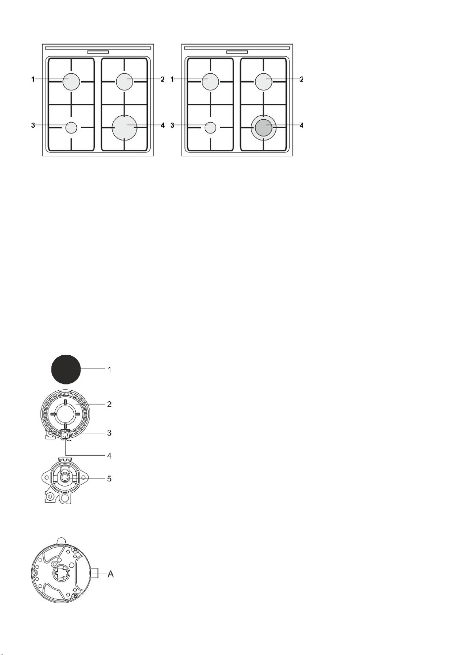
COOKING HOB (depending on the model)
1 cooking zone rear left
2 cooking zone rear right
3 cooking zone front left
4 cooking zone front right
ENERGY SAVING TIPS
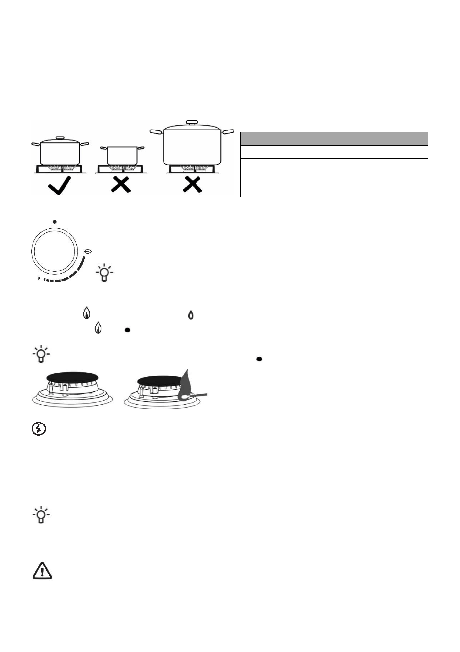
• Diameter of the pot and pan bottoms should match the diameter of the cooking zone. If the pot or pan is too small,
a part of the heat will be lost, and the cooking zone may be damaged.
• If the cooking process allows, use a lid.
• Cookware should be suitably sized given the amount of food. When you cook a small amount of food in a large pot
or pan, more energy is lost.
• If a dish takes a long time to cook, use a pressure cooker.
• Vegetables, potatoes etc. may be cooked in a smaller amount of water. The food will cook just as well, as long as
the pot is tightly closed with a lid. After bringing the water to a boil, reduce the heat to a level that just sufices to
maintain a slow simmer.
GAS BURNERS
• To sear the food, set the burner to maximum power first, and then continue to cook at minimum power.
• In some models, the cooker burners are fitted with thermoelectric safety devices. If the burner flame is extinguished
(due to boiling over, draft etc.), gas supply will be shut off automatically. Any chance of gas leaking into the room is
eliminated.
• Always place the burner cap accurately on the burner crown. Make sure the slots in the burner crown are never
blocked.
1 Burner crown cap
2 Burner crown with burner cap support
3 Thermocouple (or thermoelectric safety device, only with some models)
4 Spark plug
5 Nozzle
Triple (three-ring) burner
A Nozzle
9
TIPS REGARDING YOUR COOKWARE
• Correct choice of cookware allows optimum cooking time and gas consumption. Cookware diameter is the most
important in this respect
• If a pot or a pan is too small, the flames reaching over the edge of its bottom will damage it. Moreover, gas
consumption will be higher.
• If the pot or pan is too large, there is not enough air and the burning efficiency is decreased.
Gas hob reducer (only with some models) Use the gas hob reducer when cooking in a container of smaller diameter.
Place it on the grid over the auxiliary burner.
Burner type
Container diameter
Large (3,0 kW)
220-260 mm
Normal (1,9 kW)
180-220 mm
Auxiliary (1,0 kW)
120-180 mm
Multi-ring burner (3,6 kW)
220-260 mm
BURNER IGNITION AND OPERATION
Always press the knob before rotating it.
Cooking power levels are indicated on the knobs with a large and a small flame symbol. Rotate the knob over the large
flame position ( ) to the small flame position ( ) and back. Operating range is between the two flame symbols.
Settings between ( ) and ( ) are not recommeded. In this range, the flame is unstable and may be extinguished.
To turn off a burner, rotate the knob to the right to position ( ).
Single-handed ignition
To ignite a gas burner, press the corresponding knob and rotate it to the maximum power position. Electric spark from
the spark plug will be activated and the gas will ignite.
Two-handed ignition
To ignite a gas burner, press the corresponding knob and rotate it to the maximum power position. Press the spark
plug button.
Electric spark from the spark plug will be activated and the gas will ignite.
Electric ignition will only work if the power cord is connected to the power mains. If electric ignition does not work
due to a power supply failure or damp spark plugs, the gas can still be ignited with a match or a lighter.
After ignition, keep the knob depressed for approximately 5 more seconds until the flame is stabilized.
If the burner does not ignite in 15 seconds, close it and wait for at least 1 minute. Then repeat the ignition
process. If the flame on a burner is extinguished (regardless of the reason), close the burner and wait for 1
minute before trying to ignite it again.
10
First ignite the gas burner and then place the cookware on it. Take care of your own safety, never lean
over a lit burner during igniting or cooking.
ELECTRONIC TIMER
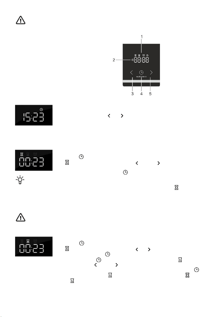
User interface
1. Timer function display
2. Power on light indicator
3. ʺLessʺ button
4. Time button
5. ʺMoreʺ button
Set the current time
When you connect the appliance to the mains electricity for the first time, the display lights up.
After three seconds the clock symbol and ʺ12:00ʺ will flash on the display. You can set the
time values by pressing back ʺ ʺ or ʺ ʺ forward icons. After 10 sec. display automatically
confirm the settings, appliances is ready to use.
The current time can be set:
• when the appliance is connected to the mains for the first time,
• in standby, when you press the time button twice,
• after power fallout.
Setting a preparation time
Select an oven function using the ʺoven function knobʺand set the temperature. Press the
ʺtimer buttonʺ to select the ʺpreparation timeʺ function. The pictogram for the ʺpreparation
timeʺ lights up on the display. Press the less ʺ ʺ or more ʺ ʺ button to set the preparation
time. The settings are automatically confirmed after 10 seconds. The settings can also be
confirmed by pressing the "timer button" . The elapsed preparation time will be displayed.
After turning on the oven using the "oven function switch", the electronic timer automatically (after 3 seconds)
offers the option of setting the duration of baking. The display flashes and the ʺpreparation time" symbol is lit up. If
duration is not set within 5 seconds, the timer switches into standby and duration of baking is not under time control.
The current time is displayed.
After the set baking duration expires, a sound signal is heard and the oven is switched off. The oven can be turned off
with the "oven function switch". To stop the sound signal, press any button on the timer.
If the oven is not turned off and the sound signal is stopped by pressing any button, the oven restarts
and the baking continues.
Setting a preparation time and end time
Select an oven function using the ʺoven function knobʺand set the temperature. Press the
ʺtimer buttonʺ to select the ʺpreparation timeʺ function. The pictogram for the ʺpreparation
timeʺ lights up on the display. Press the less ʺ ʺ or ʺ ʺ more button to set the preparation
time. Press the ʺtimer buttonʺ to save the set time.
Press the ʺtimer buttonʺ again twice. The pictogram for the ʺend timeʺ lights up on the
display. Press the less ʺ ʺ or more ʺ ʺ button to set. The settings are automatically confirmed
after 10 seconds. The settings can also be confirmed by pressing the "timer button" .
The oven starts operating before the planned "end time" depending on the desired ʺpreparation time" . When the
oven achieves the set "end time" the oven is switched off.
Example: The set "duration of baking" is 30 minutes. The end time is at 12:00. The oven starts operating at 11:30 and
the remaining time is displayed on the screen. At 12:00 the oven automatically switches off.
11
After the set baking duration expires, a sound signal is heard and the oven is switched off. The oven can be turned off
with the "oven mode selection switch". To stop the sound signal, press any button on the timer.
INFORMATION!
Setting a preparation time and end time cannot be set for the grill and grill with fan systems.
ʺTIMER ALARMʺ function
The ʺtimer alarmʺ function can be used independently of the oven. The highest possible
setting is 23 hours and 59 minutes. The last minute of the run time is displayed in seconds.
After the set baking duration expires, a sound signal is heard. To stop the sound signal, press
any key on the programme clock. The programme clock switches into the standby mode and
the display shows the current time.
You can cancel all timer functions by setting the time to ʺ0ʺ. If the appliance has been inactive
for a few minutes, it will switch to standby. The current time appears and the selected timer
function will light up.
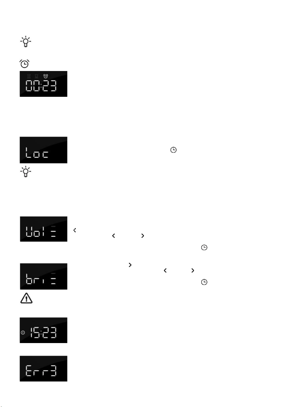
ADDITIONAL FUNCTIONS
Child lock
With the child lock you can lock the oven while in operation. You can also lock the programme
clock while baking with a set programme, thus preventing unwanted use of the oven. The child
lock is activated by pressing the "timer button" button for 5 seconds.
The display will read ‘‘Locʺ for 5 seconds. This indicates that all functions are locked. To
deactivate the child lock, press the button again for a few seconds.
Once the child lock is activated and no timer function has been set (only the clock is displayed), the oven will
not work. If the child lock is activated after a timer function has been set, the oven will work; however, the settings
cannot be changed.
When the child lock is activated, oven functions or additional functions cannot be changed. The cooking process can
only be ended by turning the ʺOven function knobʺ to ʺ0ʺ. The child lock remains activated even after the oven has
been switched off. The child lock needs to be deactivated before you can select a new programme.
Sound signal
The volume of the sound signal can be set if no timer function has been activated. The
appliance is in standby mode and only the current time is displayed. Press and hold the less
ʺ ʺ button for 5 seconds. ʺVollʺ appears on the display followed by several bars that are fully
lit. Press the less ʺ ʺ or more ʺ ʺ button to select one of three volume levels (one, two or
three bars) or no sound (Off). The settings are automatically confirmed after 5 seconds. The
settings can also be confirmed by pressing the "timer button" .
Reduce display contrast
Press and hold the more ʺ ʺ button for 5 seconds. ʺBriʺ appears on the display followed by
several bars that are fully lit. Press the less ʺ ʺ or more ʺ ʺ button to adjust the dimming level
(one, two or three bars). The settings are automatically confirmed after 5 seconds. The
settings can also be confirmed by pressing the "timer button" .
Increasing the brightness of the LED may increase standby power consumption.
Power on light indicator
The light in the oven lights when the oven function is selected using the "oven mode selection
switch".
Error indication
In case of error, display shows “ERR” text and number of mistake. Please inform service
department.
12
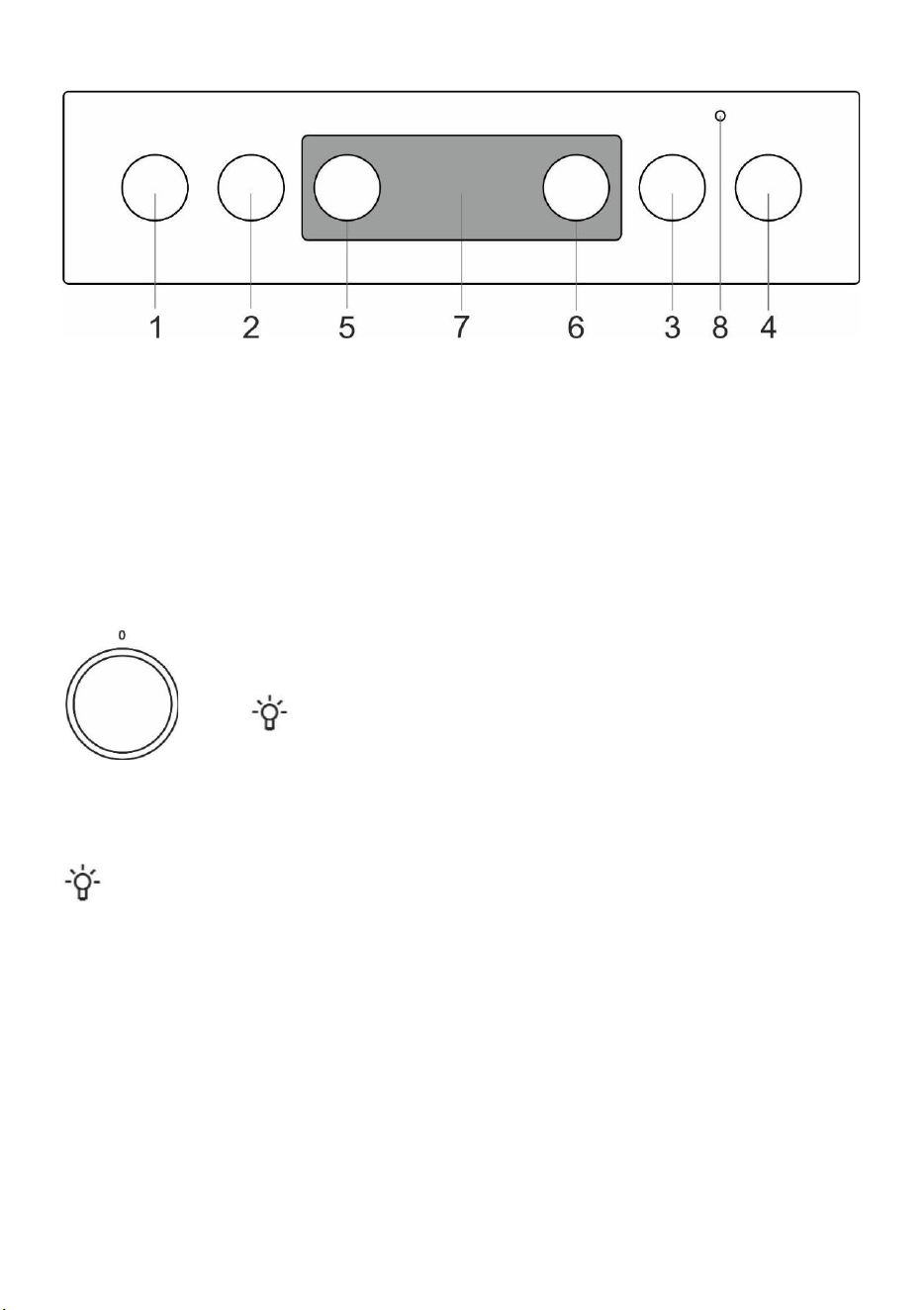
CONTROL UNIT
1. Cooking zone knob front left
2. Cooking zone knob rear left
3. Cooking zone knob rear right
4. Cooking zone knob front right
5. Cooking system selector knob
6. Oven temperature knob
7. Electronic timer
8. Oven control lamp. The lamp is lit when the oven is heating up; when the selected temperature is reached, it goes
off.
OVEN (depending on the model)
OPERATING THE OVEN
The oven can be operated with the knob for "oven mode selection" to select the function and "temperature setting" to set
the temperature.
Rotate the knob (left and right) to select COOKING SYSTEM.
Settings can also be changed during the cooking process.
OVEN OPERATION
Operation temperature is set with the temperature selector, ranging from 50 – 275/300°C. Clockwise rotation of the
selector sets higher temperature, and vice versa, anticlockwise turning reduces the temperature.
Forcible overturning of the zero position will lead to the thermostat damage!
SWITCHING OFF THE OVEN
Turn the COOKING SYSTEM SELECTOR KNOB to position "0".
OVEN LIGHT
With all modes of operation, the oven lighting is turned on automatically when the operation mode is selected.
13
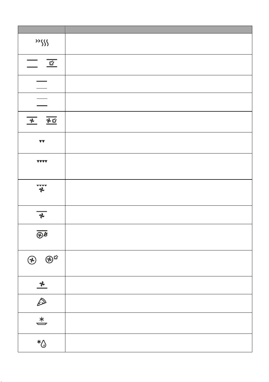
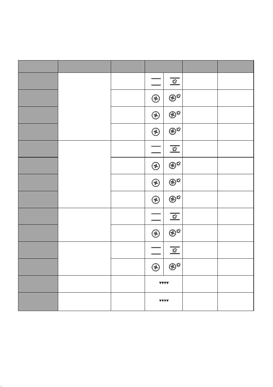
COOKING SYSTEMS (depending on the model)
System
Description
RAPID PREHEAT
Use this function if you wish to heat the oven to the desired temperature as quickly as
possible. This function is not appropriate for cooking food. When the oven heats up to the
desired temperature, the heating process is completed. Suggested temperature: 50-max°C.
UPPER AND BOTTOM HEATER *
The heaters in the bottom and in the ceiling of the oven cavity will radiate heat evenly into
the oven interior. Pastry or meat can only be baked/roasted at a single height level.
Suggested temperature: 200°C.
TOP HEATER
Only the heater on the oven cavity ceiling will radiate heat onto the food. Use it to brown the
upper side of your dish (final browning). Suggested temperature: 180°C.
BOTTOM HEATER
Only the heater on the bottom of the oven cavity will radiate heat. Use this heater to brown
the lower side of the dish. Suggested temperature: 180°C.
TOP AND BOTTOM HEATER WITH FAN *
Both heaters and the fan are activated. The fan allows even circulation of hot air inside the
oven. It is used for baking pastry, for defrosting, and for drying fruit and vegetables.
Suggested temperature: 180°C.
GRILL
Only grill heater, a part of the large grill set, will operate. This system is used for grilling a
smaller amount of open sandwiches or beer sausages, and for toasting bread. Maximal
allowed temperature: 230°C.
LARGE GRILL
The upper heater and the grill heater will operate. The heat is radiated directly by the grill
heater installed in the oven ceiling. To boost the heating effect, the upper heater is activated
as well. This combination is used for grilling a smaller amount of open sandwiches, meat or
beer sausages, and for toasting bread. Maximal allowed temperature: 230°C.
GRILL WITH FAN
Grill heater and the fan will operate. This combination is used to grill meat and to roast larger
chunks of meat or poultry at a single height level. It is also appropriate for dishes au gratin
and for browning to a crispy crust. Suggested temperature: 170°C. Maximal allowed
temperature: 230°C.
TOP HEATER AND FAN
The top (upper) heater and the fan will operate. Use this system to roast larger chunks of
meat and poultry. It is also suitable for dishes au gratin. Suggested temperature: 170°C.
INTENSIVE BAKING (AIR FRY)
This cooking method results in a crunchy crust without added fat. This is a healthy version
of fast-food frying, with fewer calories in the cooked food. Suitable for smaller cuts of meat,
fish, vegetables, and frozen products ready for frying (French fries, chicken nuggets).
Suggested temperature 200-220°C.
HOT AIR *
Round heater and the fan will operate. The fan installed in the back wall of the oven cavity
makes sure the hot air constantly circulates around the roast or pastry. This mode is used
for roasting meat and baking pastry at several levels simultaneously. Suggested
temperature: 180°C.
BOTTOM HEATER AND FAN
This is used for baking leavened but low-rising pastry and for preserving fruit and vegetables.
Suggested temperature:180°C.
PIZZA SYSTEM
This program with setting of baking temperature reaching at least 275°C was specifically
designed to help you bake the perfect pizza, focaccia, flatbread and similar baked delicacies.
BAKING FROZEN FOOD
This method allows baking frozen food in a shorter period of time without pre-heating.
Optimum for pre-baked frozen products (bakery products, croissants, lasagne, French fries,
chicken nuggets), meat and vegetables. Suggested temperature: 190-200°C.
DEFROSTING
The air circulates with no heaters activated. Only the fan will be activated. This is used to
slowly thaw frozen food. Suggested temperature: 0°C.
14
System
Description
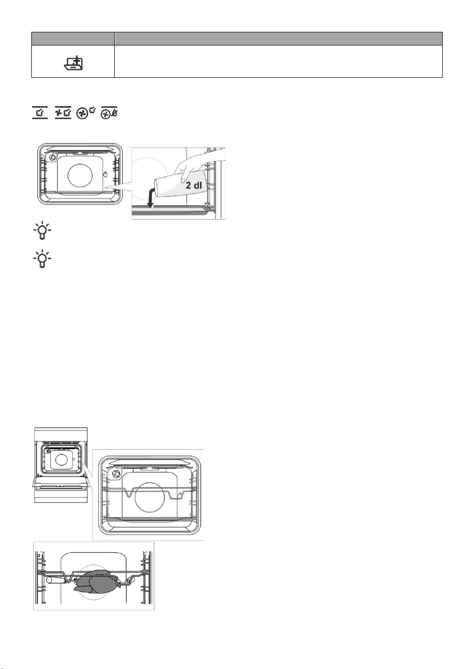
AQUA CLEAN
Only the bottom heater will radiate heat. Use this function to remove stains and food residues
from the oven. The program takes 30 minutes. Suggested temperature: 70°C.
* It is used for determining the energy efficiency class pursuant to the EN 60350-1 standard.
BAKING WITH STEAM
With these systems, you can cook with the addition of steam. Steam results in better browning
and more crunchiness of the surface.
Place a baking sheet into the first guide when the oven
is still cool. Pour a maximum of 2 dl of water onto the
baking sheet. Place the food to be cooked on the
second rack and start the system.
Do not insert the deep baking tray into the first guide, insert it one level higher.
For optimum operation of the function, do not open the oven door and do not add water during the cooking
process.
DESCRIPTIONS OF SYSTEMS
• Heating an empty oven consumes a lot of energy. Hence, baking several types of pastry or several pizzas
successively will save a lot of energy as the oven will already have been preheated.
• Use dark, black silicon-layered or enamel-coated baking sheets and trays as they conduct the heat very well.
• When using parchment paper, make sure it is resistant to high temperatures.
• When preparing food, a lot of steam is formed inside the oven, which is drained through the chimney at the back of
the appliance. The steam might condense on the door and lid of the appliance (depending on the model). This is a
standard phenomenon which has no effect on the operation of the appliance. After the end of the cooking proces,
wipe the overflowing condensed water with a cloth.
• Switch off the oven approximately 10 minutes before the end of the cooking process to save energy by making use
of the accumulated heat.
• Do not cool the food in a closed oven to prevent condensation (dew).
Cooking with the rotisserie (depending on the model)
Maximum temperature when using the rotisserie is 230°C.
Insert the skewer support into the 3rd guide from the bottom and
place the shallow baking sheet into the bottom (1st) guide to
serve as a drip tray.
Impale the meat on the skewer and tighten the screws.
Place the skewer handle on the front skewer support and insert
the tip into the opening in the right hand side of the rear oven
cavity wall (the opening is protected with a rotating cover).
Undo the skewer handle and close the oven door.
Switch on the oven and select the LARGE GRILL system.
15
The grill shall only be used when the oven door is closed. Do not use the grill on position 4.
Do not insert the deep baking tray into the first guide.
MAINTENANCE & CLEANING
Be sure to unplug the appliance from the power supply and wait for the appliance to cool down. Children
should not clean the appliance or perform maintenance tasks without proper supervision.
Aluminium finish (gas burner)
Clean the aluminium finish with non-abrasive liquid cleaners intended for such surfaces. Apply the cleaner onto a wet
cloth and clean the surface. Then, rinse the surface with water. Do not apply the cleaner directly onto the aluminium
finish. Do not use abrasive cleaners or sponges.
The aluminium-coated surfaces should not come into contact with oven cleaning sprays as this may result in
visible and permanent damage.
Stainless steel sheet front side of the housing (depending on the model)
Clean this surface only with a mild detergent (soapsuds) and a soft sponge that will not scratch the finish. Do not use
abrasive cleaners or cleaners containing solvents as they may damage the housing finish.
Lacquer-coated surfaces and plastic parts (depending on the model)
Do not clean the knobs and buttons, door handles, stickers, and rating/type plates with abrasive cleaners or abrasive
cleaning materials, alcohol-based cleaners, or with alcohol. Immediately remove any stains with a soft non-abrasive
cloth and some water, in order to avoid damaging the surface. You may also use cleaners and cleaning materials
intended for such surfaces as instructed by their respective manufacturers.
Enamel surfaces (oven, cooking hob)
Use a damp sponge with detergent for cleaning. Fatty stains can be removed with warm water and special detergent
for enamel. Never clean enamelled surfaces with abrasive means producing irremovable damage to the appliance
surface.
Glass surfaces
Do not use rough abrasive cleaning agents or sharp metal scrapes for cleaning of oven door glass, as they could crack
the surface and causing the breaking of glass. Clean the glass surfaces with special means for glass, mirrors and
windows.
INFORMATION!
Never use aggressive or abrasive cleaners.
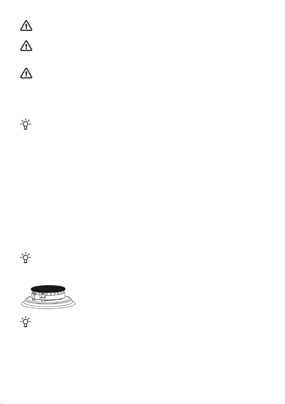
GAS BURNER
The grid, cooking surface, and burner parts may be cleaned in hot water with some
washing up detergent. Do not clean them in a dishwasher. Clean the thermocouple and
the spark plug with a soft brush. These parts have to be spotlessly clean to function
correctly. Clean the burner crown and cap. Make sure the slots on the burner crown are
not clogged or otherwise blocked. After cleaning, thoroughly dry all the parts and
reassemble them correctly. Any party placed askew will make burner ignition harder.
Burner caps are finished in black enamel. Due to high temperatures, discoloration cannot be avoided. However,
it does not affect burner operation.
OVEN
Clean the oven walls with a damp sponge and detergent. To clean stubborn stains burned into the oven wall use a
special detergent for enamel. After cleaning carefully wipe the oven dry. Clean the oven only when it is completely
cold. Never use abrasive agents, because they will scratch enameled surface. Wash the oven utensils with a sponge
and detergent. You can also use special detergents to remove rough stains or burns.
16
USING THE „AQUA CLEAN“ FUNCTION
Turn the COOKING SYSTEM SELECTOR KNOB to position AQUA CLEAN . Set the TEMPERATURE KNOB to
70°C. Pour 0,6 l water into a baking tray and place it in the lower guide. After 30 minutes, food residues on the oven
enamel walls will have softened and they will be easy to clean with a damp cloth.
Use the “AQUA CLEAN“ system when the oven has fully cooled down.
REMOVING AND CLEANING WIRE AND TELESCOPIC EXTENDIBLE GUIDES
Only use conventional cleaners to clean the guides.
Hold the guides by the bottom side and pull them towards the center of the oven cavity. Remove them from the
openings at the top.
Do not clean the extendible guides in the dishwasher.
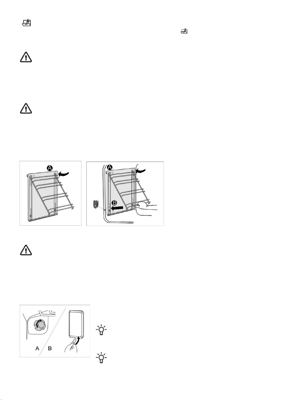
INSTALLING THE CATALYTIC INSERTS
Only use conventional cleaners to clean the guides.
Remove the wire guides or extendible guides. (depending on the model)
Mount catalytic inserts onto the wire guides. The upper part of the guides must be mounted into the upper openings
"A" in the catalytic inserts.
Place the wire guides with the catalytic inserts on the upper openings in the side walls of the oven “A“.
Press them into the snap lock at the bottom “B“.
Do not wash the catalytic inserts in the dishwasher.
REPLACING THE BULB
The bulb is a consumable and therefore not covered by warranty. Before changing the bulb, remove the trays, the grid,
and the guides.
Disconnect the appliance from the power mains!
Halogen lamp: G9, 230 V, 25 W. (regular bulb E14, 230 V, 25 W - depending on the model)
A Undo the bulb cover and pull out or undo the bulb.
Use protection to avoid burns.
B Use a flat screwdriver to release the bulb cover and remove it. Remove the bulb.
Be careful not to damage the enamel.
17
COMFORT DOOR CLOSING (depending on the model)
Cookers are equipped with new secure door hinges COMFORT. These special hinges guarantee very quiet and gentle
closing of the oven door.
If the force applied to close the door is too strong, the efficiency of the system can be reduced or the
system's safety can be affected.
DOOR LOCK (depending on the model)
Open the door lock by gently pushing it to the right with your thumb while simultaneously pulling the door outwards.
When the oven door is closed, the door lock automatically returns to the initial position.
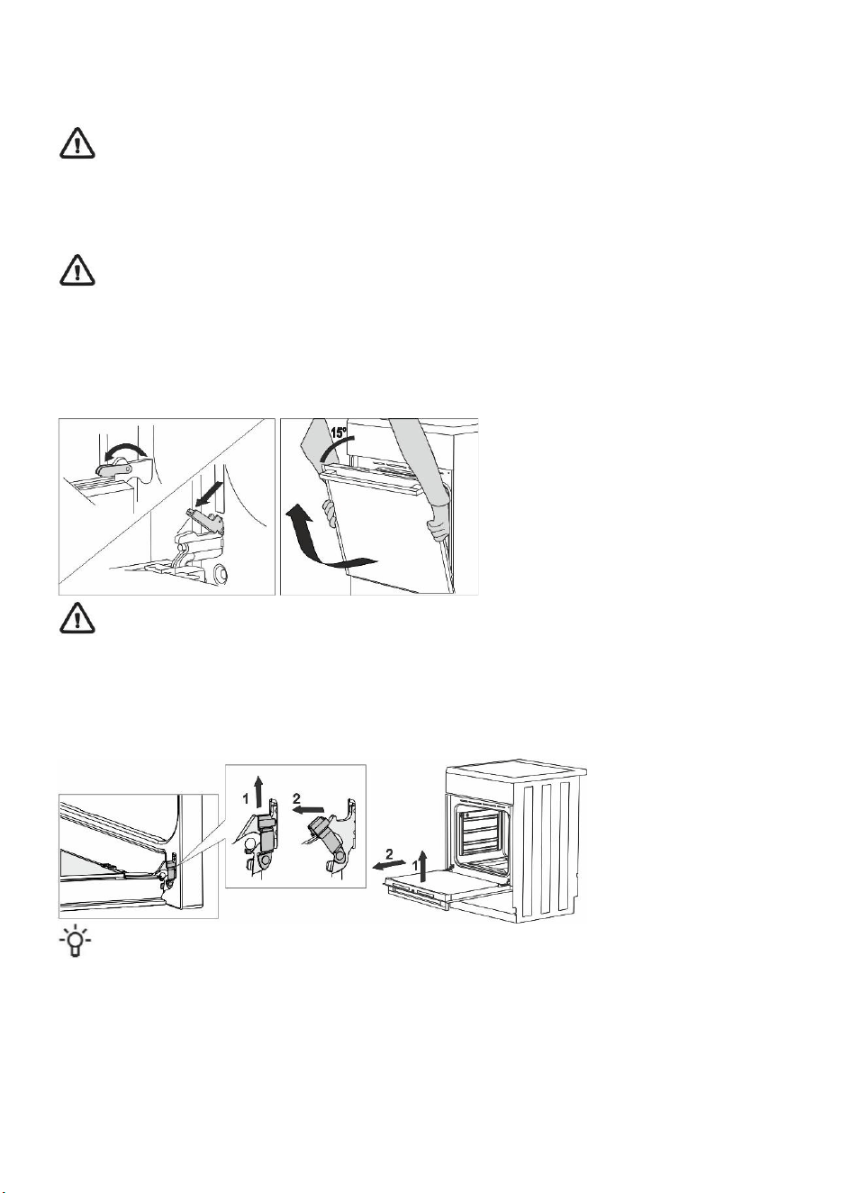
REMOVING AND REPLACING THE OVEN DOOR (depending on the model)
• Open the oven door (up to end position).
• Rotate the flaps of door hinges (in case of conventional closing). At COMFORT soft closing system, rotate the flaps
by 90°.
• Slowly close the oven door until the flaps fit together with the hinges in the side laths of the door. At the angle of
15° (regarding to the closed door position), slightly close the door and pull it out from both hinges of the appliance.
Before replacing the door, always check that the hinge flaps are correctly placed in the side laths of
the door. You prevent the sudden closing of the hinge so, which is connected to a strong spring. The
releasing of flap causes the damaging of door and a risk of injury.
REMOVING AND REPLACING THE OVEN DOOR (depending on the model)
• Open the oven door (up to end position).
• Raise up and turn the flaps.
• Slowly close the oven door, lift it slightly and pull it out from the both hinges of the appliance.
Provide these steps in reverse order at returning the door back. If the door does not open or close properly,
make sure, that the hinges are correctly located on their hooks.
18
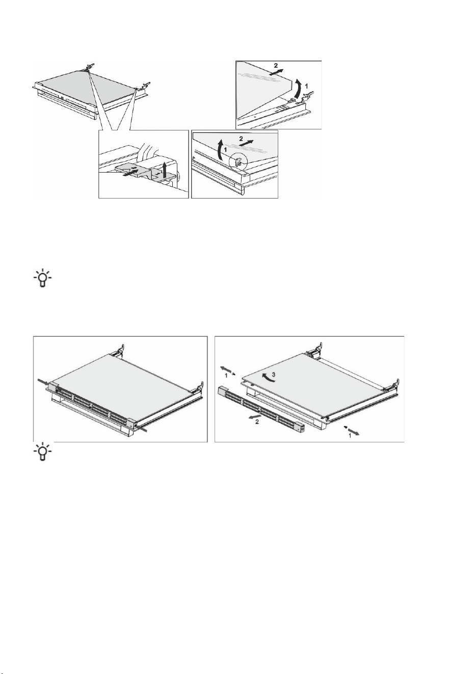
REMOVING AND INSERTING THE OVEN DOOR GLASS PANE (depending on the model)
Oven door glass pane can be cleaned from the inside, but it has to be removed first. Remove the oven door (see
chapter "Removing and replacing the oven door".
• Slightly lift the supports on the left and right side of the door (marking 1 on the support) and pull them away from the
glass pane (marking 2 on the support).
• Hold the door glass pane by the lower edge; slightly lift it so that it is no longer attached to the support; and remove
it.
• To remove the third glass pane (only with some models), lift and remove it. Also remove the rubber seals on the
glass pane.
To replace the glass pane, observe the reverse order. The markings (semicircle) on the door and the glass pane
should overlap.
REMOVING AND INSERTING THE OVEN DOOR GLASS PANE (depending on the model)
Screw out the screws on the door left and right sides and pull out the upper lath. You can pull out the glass pane of
door now.
Provide these steps in reverse order at returning the glass pane back.
Repair or any warranty claim resulting from incorrect connection or use of the appliance shall not be covered
by the warranty. In this case, the user will cover the cost of repair.
19
INSTALLATION AND CONNECTION INSTRUCTIONS
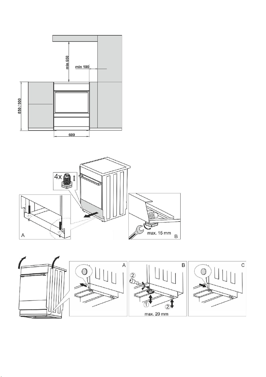
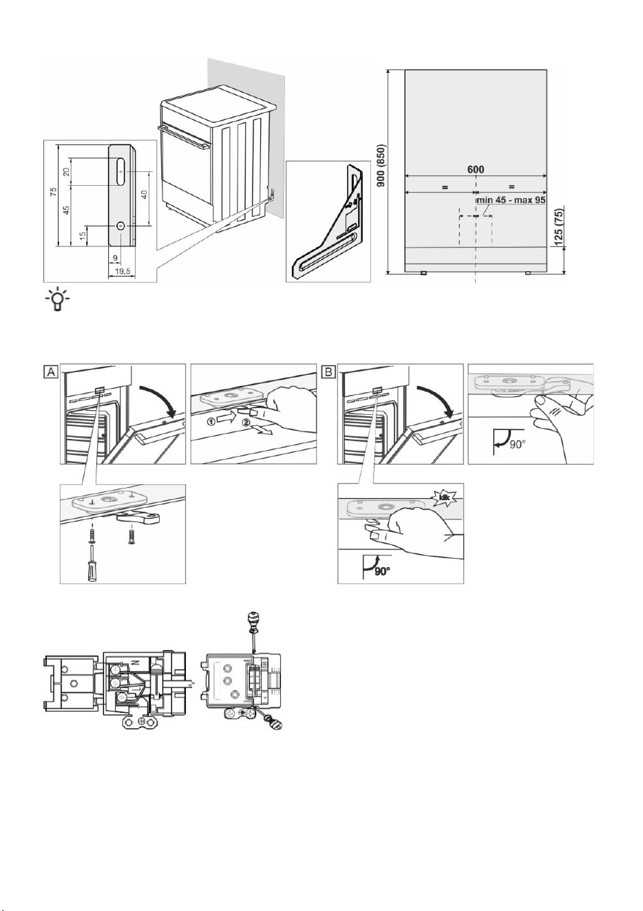
APPLIANCE PLACEMENT (mm) (depending on the model)
The walls or furniture adjacent to the appliance (floor, rear
kitchen wall, side walls) have to be temperature-resistant to at
least 90°C.
LEVELLING THE APPLIANCE AND ADDITIONAL SUPPORT (depending on the model)
A) The height of the cooker is 850 mm. You can adjust the height of the appliance from 850 to 865 mm.
B) The height of the cooker is 900 mm. Depending on the model, you can adjust the height of the appliance from 850
to 920 mm or from 900 to 920 mm.
20
ADJUSTING THE HEIGHT OF THE COOKER (depending on the model)
The height of the cooker is 900 mm. You can adjust the height of the appliance from 850 to 940 mm.
Torx T20
• Put the cooker on the floor with back side.
• Unscrew the screws, see arrows.
• Set the desired height.
• Screw the screws back together
The cooker must be installed horizontally!
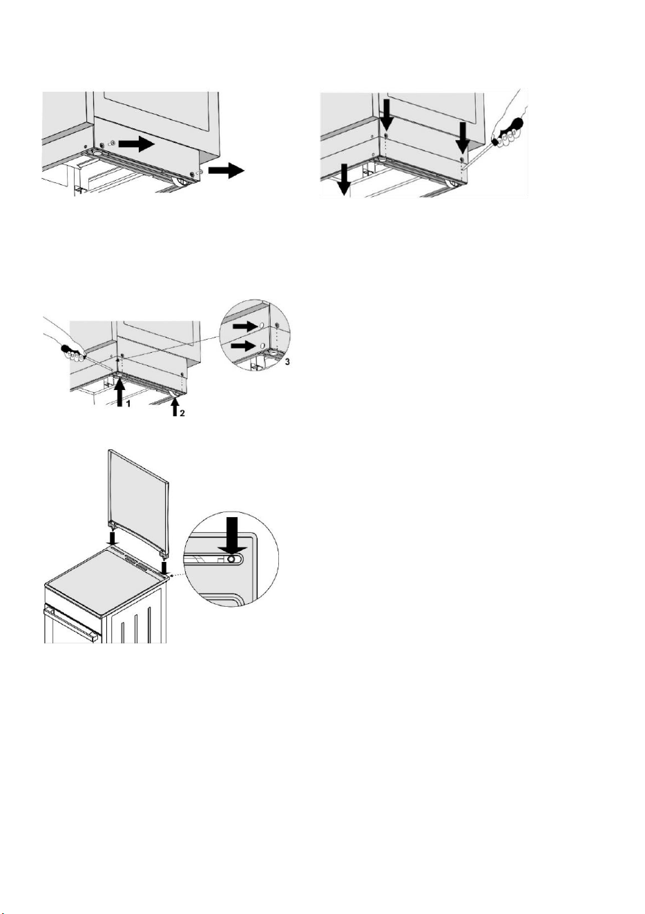
Follow these steps:
• Rotate the height adjustment screws (see figure 1) to adjust
the height of the cooker to the correct position.
• Adjust the wheels (see figure 2) by screwing them with two
screws at the front of the skirting board. Check the horizontal
position of the stove using a spirit level.
• Place the blind plugs into the holes in the front of the skirting
board (see Figure 3).
INSTALLATION OF THE LID (depending on the model)
21
PREVENTION FROM TIPPING OVER (mm) (depending on the model)
According to the plan attach the holder to the wall with the added screws and anchors. If the attached screws
and anchors cannot be used, use others that will ensure a secure installation on the wall.
INSTALLATION OF THE DOOR LOCK (depending on the model)
CONNECTING TO THE POWER MAINS
Make sure the power cord is not located near hot parts and
sharp edges.
If the power cord is damaged, it should be replaced by the
manufacturer or an authorized service technician, in order to
avoid hazard.
22
CLAMP PROTECTION
The clamps should be protected by a clamp cover, see additional equipment. Electric shock danger.
GAS CONNECTIONS
FACTORY DEFAULT SETTINGS
• Gas appliances are tested and fitted with the sign.
• Has appliances are supplied sealed with burners adjusted to natural gas type H or E (20 or 25 mbar), or to liquefied
natural gas (50 or 30 mbar).
• The adjustment conditions for this appliance are stated on the label (or data plate).
• Before connecting the appliance, make sure the local requirements for connection (gas type and pressure) are
compatible with the appliance settings.
• If the gas you are using is not compatible with the current settings on your appliance, call a service technician or the
distributor.
• Modifying the hob to operate with a different type of gas requires replacement of the nozzles (see section NOZZLE
TABLE).
• In case of repairs or if the seal is damaged, the functional parts have to be tested and re-sealed in compliance with
the installation instructions. The functional parts include the following: fixed nozzle for large flame and adjustable
regulation screw for small flame.
CONNECTING TO GAS SUPPLY
• Appliance has to be connected to the gas mains or the gas cylinder according to the instructions of your local gas
distribution company.
• There is a gas connection plug on the right-hand side of the appliance, with external thread EN ISO 228-1 or EN
10226-1 / -2 (depending on the connection regulations in the respective country).
• A liquefied natural gas connection and a non-metal gasket are also supplied. (depending on the model)
• When connecting the appliance to the gas supply, the G 1/2 or R 1/2 part has to be held to prevent it from rotating.
(depending on the model)
• Use approved non-metal gaskets and approved sealants for sealing the connection joints. Only use each gasket
once. The thickness of flat non-metal gaskets may be deformed by up to 25%.
• Connect the appliance to the gas supply using a certified flexible hose. The hose should not touch the upper part of
the appliance.
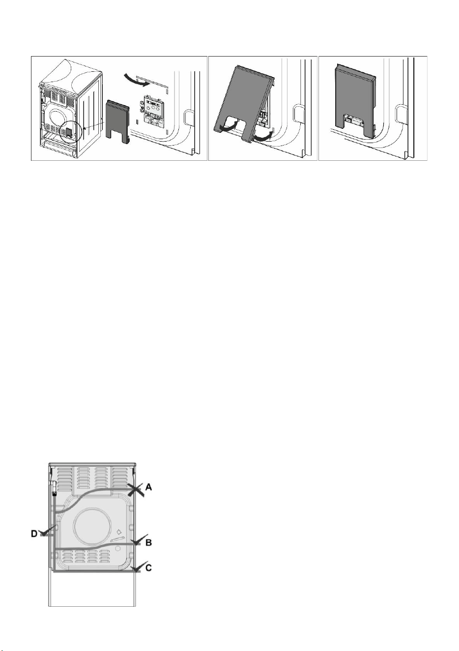
Connection with a flexible hose
If the appliance is connected with a flexible hose, the path of the hose
indicated with "A" is not acceptable.
If a metal pipe is used, option "A" is permissible as well.
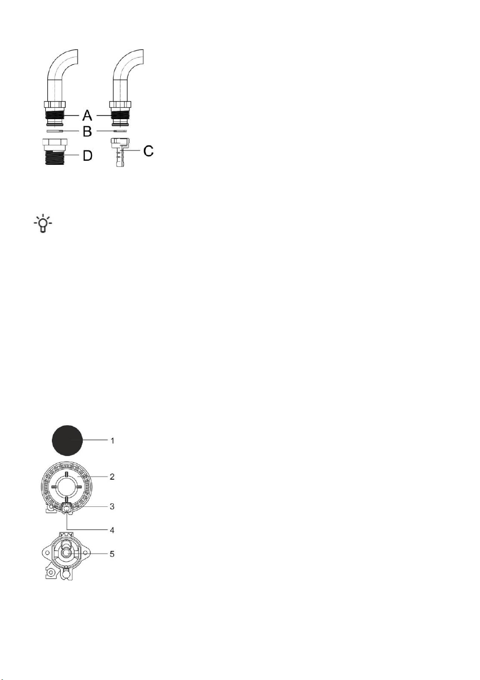
23
Gas connection plug
A Connection EN ISO 228-1
B Non-metal gasket, thickness 2 mm
C Hose plug for liquefied natural gas (depending on the connection
regulations in the respective country)
D Connection EN 10226-1 / -2 depending on the connection regulations
in the respective country).
After connection, check the operation of the burners. The flames have to burn with clearly visible blue and green core.
If the flame is unstable, increase the minimum power as necessary. Explain to the user how the burners operate and
review the instruction manual together.
After connecting the appliance, check the seal on all joints.
MODIFYING THE BURNERS FOR USE WITH A DIFFERENT TYPE OF GAS
• Modifying the burners for use with a different type of gas does not require removing the hob from the countertop.
• Before making the modifications, unplug the appliance from the power mains and shut off the gas supply valve.
• Replace the existing nozzle for the nominal heat load with suitable nozzles for the new type of gas (see table).
• When modifying the appliance for use with liquefied natural gas, tighten the minimum heat load regulation screw all
the way to reach the minimum heat load.
• When modifying the appliance for use with natural gas, undo the minimum heat load regulation screw to reach the
minimum heat load, but by no more than 1.5 turns.
After modifying the appliance for use with a different type of gas, replace the old sticker with gas type information
(on the rating plate) with the relevant new sticker and test the functionality and sealing of the appliance.
Make sure the electric conductors, thermostat capillary, and thermo elements do not protrude into the gas flow area.
Adjustment elements
• Adjustment elements for minimum heat load of the burners are accessible through the openings on the control panel.
• Remove the control knobs.
Cooking burner
1 Burner crown cap
2 Burner crown with burner cap support
3 Thermocouple (or thermoelectric safety device, only with some models)
4 Spark plug
5 Nozzle
24
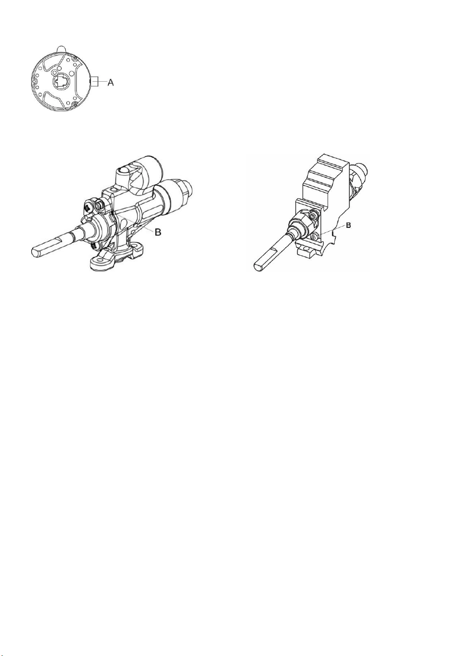
Triple (three-ring) burner
A Nozzle
Gas valve with a safety device
B Minimum heat input regulation screw
Copreci Sabaf

25
DISPOSAL
Packaging is made of environmentally friendly materials that can be recycled, disposed of, or
destroyed without any hazard to the environment. To this end, packaging materials are labelled
appropriately.
The symbol on the product or its packaging indicates that the product should not be treated as
normal household waste. The product should be taken to an authorized collection center for waste
electric and electronic equipment processing.
Correct disposal of the product will help prevent any negative effects on the environment and health
of people which could occur in case of incorrect product removal. For detailed information on removal
and processing of the product, please contact the relevant municipal body in charge of waste
management, your waste disposal service, or the store where you bought the product.
We reserve the right to any changes and errors in the instructions for use.
26
COOKING TEST
Tested in compliance with the EN 60350-1 standard.
BAKING
Dish
Equipment
Guide (from
the bottom)
System
Temperature
(°C)
Cooking time
(minutes)
Cookies
single level
shallow enamel-
coated baking sheet
3
140-150*
20-35
Cookies
single level
3
140-150*
20-35
Cookies
two levels
2, 3
140-150*
30-45
Cookies
three levels
2, 3, 4
130-140*
30-45
Cupcakes
single level
shallow enamel-
coated baking sheet
3
160-170*
20-35
Cupcakes
single level
3
160-170*
20-35
Cupcakes
two levels
2, 3
140-150*
30-45
Cupcakes
three levels
2, 3, 4
140-150*
35-50
Cake
round metal mould
ø26/wire shelf
(support grid)
2
160-170*
20-35
Cake
2
160-170*
20-35
Apple pie
2x round metal mould
ø20/wire shelf
(support grid)
2
170-180
50-70
Apple pie
3
160-170
50-70
Toast
wire shelf/grid
4
230*
0,5-3
Minced meat
patty
wire shelf (support
grid) + shallow baking
sheet as drip tray
4
230
20-35
* Preheat for 10 minutes.
27
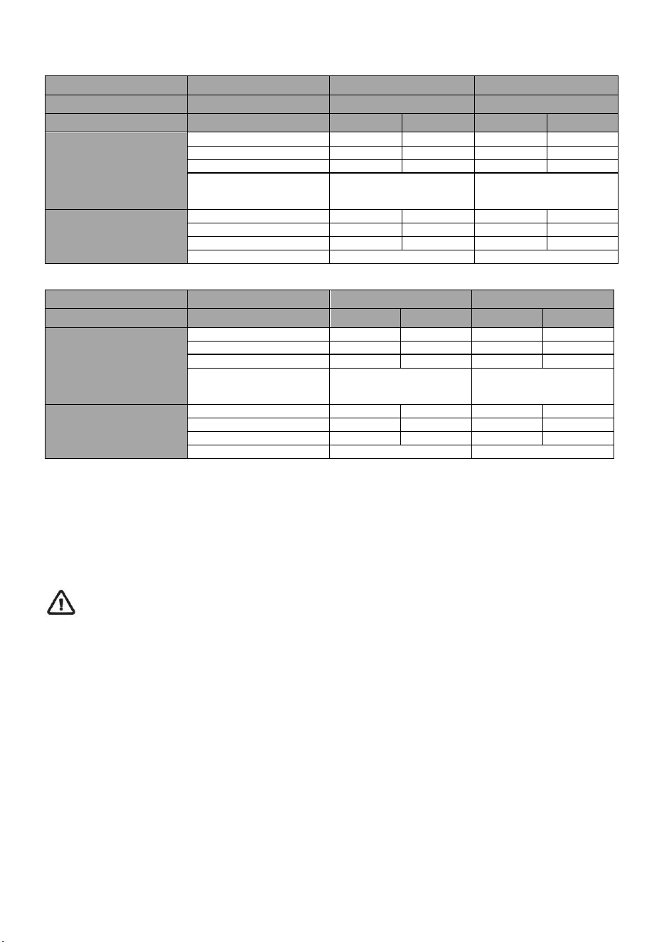
NOZZLE TABLE
Gas type, pressure
Auxiliary burner
Normal burner
Wobbe number
Standard
max
min
max
min
Natural gas H
Wo=45,7÷54,7 MJ/m
3
Natural gas E
Natural gas E+
Wo=40,9÷54,7 MJ/m
3
G20, p=20 mbar
Nominal heat load (kW)
1,0
0,48
1,9
0,48
Consumption (l/h)
95
46
181
46
Nozzle type (1/100 mm)
72 X
26
1)
/ 35
2)
103 Z
26
1)
/ 35
2)
Nozzle ID
690771
568169
Liquefied gas 3B/P
Wo=72,9÷87,3 MJ/m
3
G30, p=30 mbar
Nominal heat load (kW)
1,0
0,48
1,9
0,48
Consumption (g/h)
73
35
138
35
Nozzle type (1/100 mm)
50
26
1)
/ 35
2)
68
26
1)
/ 35
2)
Nozzle ID
690780
568175
Gas type, pressure
Large burner
Multi-ring burner
Wobbe number
max
min
max
min
Natural gas H
Wo=45,7÷54,7 MJ/m
3
Natural gas E
Natural gas E+
Wo=40,9÷54,7 MJ/m
3
G20, p=20 mbar
Nominal heat load (kW)
3,0
0,76
3,6
1,56
Consumption (l/h)
286
72
343
149
Nozzle type (1/100 mm)
130 H3
33
1)
/ 46
2)
145 H3
57
1)
Nozzle ID
574285
568170
Liquefied gas 3+, B/P
Wo=72,9÷87,3 MJ/m
3
G30, p=30 mbar
Nominal heat load (kW)
3,0
0,76
3,5
1,56
Consumption (g/h)
218
55
255
114
Nozzle type (1/100 mm)
86
33
1)
/ 46
2)
94
57
1)
Nozzle ID
574287
568176
1)
Copreci /
2)
Sabaf
• Regulation screws for liquefied gas are installed and set in factory to the gas type for which the factory default
settings apply.
• When modifying the appliance for use with a different type of gas, the regulation screw has to be tightened or undone
to set the required gas flow (do not undo the regulation screw by more than 1.5 turns).
Burner power is indicated by observing the upper Hs caloric value.
Connection to gas supply and adjustment to a different type of gas may only be carried out by an expert
authorized by the gas distributor or an authorized service technician!
SAP 898020en


GORENJE gospodinjski aparati, d.o.o
Partizanska cesta 12, SI-3320 Velenje, SLOVENIA
2025 06 12
SAP 898020en
Made in Czech Republic