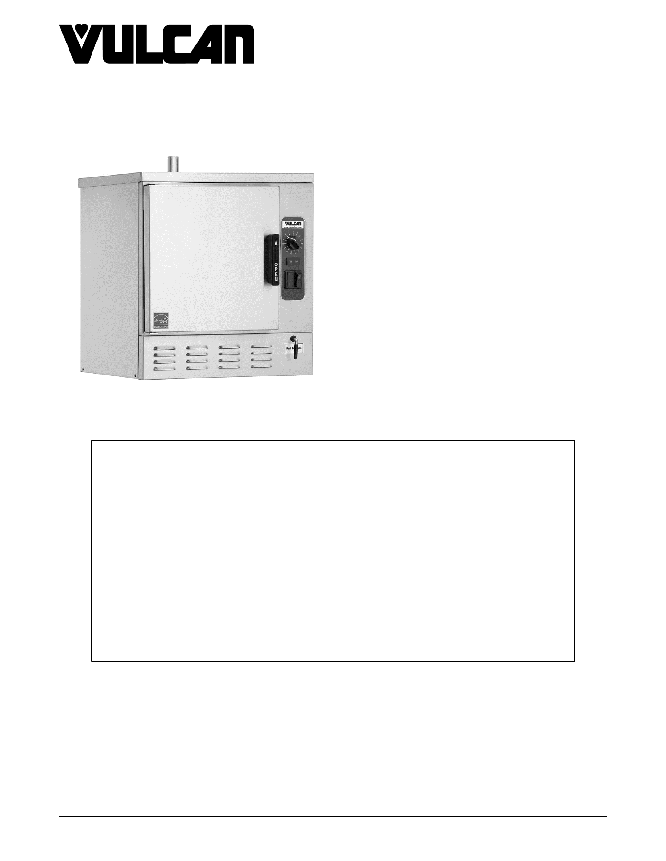
C24EO5 SHOWN
C24EO SERIES ELECTRIC
COUNTERTOP STEAMERS
C24EO3 ML-136006
C24EO5 ML-136007
AUTOFILL (OPTION) ML 152054 -
C24EO3
ML 152055 -
C24EO5
- NOTICE -
This Manual is prepared for the use of trained Hobart Service Technicians and should not
be used by those not properly qualified.
This manual is not intended to be all encompassing. If you have not attended a Hobart Service
School for this product, you should read, in its entirety, the repair procedure you wish to
perform to determine if you have the necessary tools, instruments and skills required to
perform the procedure. Procedures for which you do not have the necessary tools,
instruments and skills should be performed by a trained Hobart Service Technician.
The reproduction, transfer, sale or other use of this manual, without the express written
consent of Hobart, is prohibited.
This manual has been provided to you by ITW Food Equipment Group LLC ("ITW FEG")
without charge and remains the property of ITW FEG, and by accepting this manual you agree
that you will return it to ITW FEG promptly upon its request for such return at any time in the
future.
SERVICE MANUAL
A product of Vulcan-Hart 3600 North Point Blvd Baltimore, MD 21222
F25386 Rev. C (1023)

TABLE OF CONTENTS
SERVICE UPDATES ....................................................................................... 4
SERVICE UPDATES ................................................................................... 4
TIS DOCUMENT LIST - C24EO SERIES ELECTRIC COUNTERTOP STEAMERS ....................... 4
GENERAL .................................................................................................. 6
INSTALLATION, OPERATION AND CLEANING ......................................................... 6
INTRODUCTION ....................................................................................... 6
FEATURES ........................................................................................ 6
STEAM COOKING ................................................................................. 6
MODEL DESIGNATIONS ........................................................................... 6
EXTERIOR DIMENSIONS .......................................................................... 6
SPECIFICATIONS ...................................................................................... 6
TOOLS ................................................................................................. 6
REMOVAL AND REPLACEMENT OF PARTS ............................................................... 8
COVERS AND PANELS ................................................................................ 8
COMPONENT PANEL COMPONENTS ................................................................. 9
TIMER ................................................................................................. 9
HOLD THERMOSTAT .................................................................................. 9
HIGH LIMIT THERMOSTAT ........................................................................... 10
LOW WATER THERMOSTAT ......................................................................... 11
TEMPERATURE PROBE .............................................................................. 11
HEATING ELEMENT ASSEMBLY - REPLACEMENT ELEMENTS ...................................... 11
THREADED STUD MOUNTING OF HEATER ASSEMBLY ......................................... 11
SPRING MOUNTED HEATER ASSEMBLY (FIRST PRODUCTION) ................................ 15
MANUAL DRAIN VALVE .............................................................................. 16
DOOR ................................................................................................ 17
DOOR GASKET ....................................................................................... 17
DOOR HANDLE ....................................................................................... 17
DOOR LATCH ASSEMBLY ............................................................................ 18
DOOR HINGE BEARINGS ............................................................................. 20
REMOVAL AND REPLACEMENT (AUTOFILL OPTIONAL) ................................................. 21
PROBES .............................................................................................. 21
SOLENOID VALVES .................................................................................. 22
WATER LEVEL ALARM ............................................................................... 23
AUTOFILL CONTROL ASSEMBLY .................................................................... 23
SERVICE PROCEDURES AND ADJUSTMENTS ........................................................... 25
DOOR LATCH ADJUSTMENT ......................................................................... 25
OPENING A JAMMED DOOR ..................................................................... 25
ADJUSTMENT .................................................................................... 25
HEATING ELEMENT TEST ............................................................................ 26
TEMPERATURE CONTROL CALIBRATION ........................................................... 26
ELECTRICAL OPERATION ................................................................................ 28
COMPONENT FUNCTION ............................................................................ 28
COMPONENT LOCATION ............................................................................. 29
SEQUENCE OF OPERATION ......................................................................... 32
TIMED COOKING MODE .......................................................................... 32
CONSTANT COOKING MODE .................................................................... 33
SCHEMATIC DIAGRAM ............................................................................... 36
WIRING DIAGRAMS - HEATING ELEMENTS .......................................................... 38
C24EO3 - 208V/240V ............................................................................. 38
C24EO5 - 208V/240V ............................................................................. 39
C24EO5 - 480V ................................................................................... 40
C24EO SERIES ELECTRIC COUNTERTOP STEAMERS
F25386 Rev. C (1023) Page 2 of 44

SERVICE UPDATES
SERVICE UPDATES
October 2023
Added On/Off Switch Diagram. COMPONENT LOCATION
March 2021
Added Autofill section to SEQUENCE OF OPERATION.
March 2020
Added Notice SOLENOID VALVES.
February 2020
Added
PROBES.
SOLENOID VALVES
WATER LEVEL ALARM
AUTOFILL CONTROL ASSEMBLY
Updated
SCHEMATIC DIAGRAM
TIS DOCUMENT LIST - C24EO SERIES ELECTRIC COUNTERTOP STEAMERS
SERVICE TAB
Document Title Document Type
C24EO SERIES ELECTRIC COUNTERTOP
STEAMERS Service Manual
Service Manual
SERVICE TAB (Multimedia)
Document Title Document Type
All Stainless Steel with Automatic Timers & Manual
Boilers Direct Steam - ST. STL. LEG, Pedestal or Wall
Mounted Owners Manual
Instructions
Electric Boiler Owners Manual Instructions
Repair Flood-Damaged Food Equipment Misc
C24EO3 & C24EO5 Electric Countertop Steamers
Installation & Operation Manual
Operator
Fundamentals of Steam Service Instructions
Fundamentals of Gas Service Instructions
Hobart Water Filter Replacement Cross Reference Sheet Service Instructions
C24EO SERIES ELECTRIC COUNTERTOP STEAMERS - SERVICE UPDATES
F25386 Rev. C (1023) Page 4 of 44
SERVICE TAB (Multimedia)
Pilot & Burner Problems on Units Without Powered
Burners Service Information
Service Instructions
ScaleStick Twin System, Part No. 01-234301-51200 Service Instructions
Water Level Pressure Switches Information Service Instructions
HC24EO & C24EO - Heating Element Kit Installation Service Manual
Rating Plate Locations on Current Vulcan-Hart/Wolf
Range Equipment
Technical Service Bulletin (TSB)
SB630 Gas Range Thermocouples Technical Service Bulletin (TSB)
SB760 Vulcan Steam Temporary Service Instruction /
Inspect All Warrick Water Level
Technical Service Bulletin (TSB)
SB800 Vulcan Steam Equipment - Enhanced Ignition
Modules
Technical Service Bulletin (TSB)
SB860 Atmospheric Steamer Door Switch Actuator Rod Technical Service Bulletin (TSB)
TSB 1374 Water Level Control Part No. 844069-1
Changes
Technical Service Bulletin (TSB)
TSB 1393 Steam Cooking Equipment - Prevention,
Detection and Treatment of Corrosion on Stainless Steel
Technical Service Bulletin (TSB)
TSB 1037A Hobart to Vulcan "Common" Model Cross
Reference List
Technical Service Bulletin (TSB)
TSB 1298A Atmospheric Steamer Door Switch Actuator
Rod
Technical Service Bulletin (TSB)
TSB 1339 Vulcan High Efficiency Gas Steamers - Burner
Noise
Technical Service Bulletin (TSB)
Hobart & Vulcan Steamers/Kettles with Warrick Water
Level Control Boards
Temporary Service Instructions (TSI)
Steamers - Main Transformer Primary Tap on Electric
Machines
Temporary Service Instructions (TSI)
Steamers - Motorized Valve P/N 856718-1 Temporarily
Unavailable
Temporary Service Instructions (TSI)
Steamers Wire Insulation Pinched Under Screw Lug on
Terminal Block & Contractors
Temporary Service Instructions (TSI)
PARTS TAB
Document Title Document Type
C24EO Series Connectionless Steamer Parts Catalog
C24EO SERIES ELECTRIC COUNTERTOP STEAMERS - SERVICE UPDATES
Page 5 of 44 F25386 Rev. C (1023)
GENERAL
INSTALLATION, OPERATION AND
CLEANING
Refer to the Installation & Operation Manual for
specific instructions.
INTRODUCTION
Features
• Requires no water or drain line connections
(manual fill & manual drain).
• Cast aluminum element block for efficient heat
transfer and distribution.
• Field convertible to single phase or three phase
power depending on the supply available.
• 3.0 gallons maximum holding pan capacity.
Steam Cooking
The C24EO series steamer provides timed or
continuous mode cooking in a pressure-less
compartment. The small physical size of the steamer
offers an efficient way to produce many foods in small
batches. Pressure-less, convection steam cooking will
steam cook fresh foods or will steam defrost and cook
frozen foods providing the maximum color, flavor and
nutritional value with the least expenditure of energy
and labor. The pressureless cooking compartment
allows the operator to open and close the door,
anytime during a cooking cycle.
Model Designations
• C24EO3 - 3 pan capacity
• C24EO5 - 5 pan capacity
NOTE: based on 2.5 inch pan depth
Exterior Dimensions
• C24EO3 - 24" w x 33" d x 19.5" h
• C24EO5 - 24" w x 33" d x 26" h
SPECIFICATIONS
A potable water supply does not guarantee that it's
suitable for steam generation. The water supply must
be within the following specifications or a local water
treatment specialist may need to be consulted. If a
water treatment system is installed, it must be properly
maintained.
WATER REQUIREMENTS
• Hardness - Less than 3 grains (17.1ppm = 1 grain
of hardness)
• Silica - Less than 13 ppm
• Total Chloride - Less than 4 ppm
• Ph range of - 7.0 to 8.0
• Un-dissolved Solids - less then 5 microns
ELECTRIC
MODEL
TOTAL
KW
AMPERAGE PER LINE
3 PHASE 1 PHASE
208
V
240V 480V 208V 240V
C24EO3 8 22.2 19.2 - 38.5 33.3
C24E05 12 33.3 28.9 14.4 57.5 50.0
NOTES:
1. Amperage values in the table are
nominal. Tolerance is +5/-10%.
2. C24EO3 - Shipped for 208V 60-50
HZ 3 phase connection. Field
convertible to 240V three phase or
208/240V single phase. See wiring
diagram AI2853.
3. C24EO5 - Shipped for 208V or 240V
or 480V 60-50 HZ, 3 phase. 208V
and 240V models are field
convertible to 1 phase. See wiring
diagram (LINK to AI2852).
TOOLS
C24EO SERIES ELECTRIC COUNTERTOP STEAMERS - GENERAL
F25386 Rev. C (1023) Page 6 of 44

Standard
1. Standard set of hand tools.
2. VOM with minimum of NFPA-70E CATIII 600V, UL/CSA/TUV listed. Sensitivity of at least 20,000 ohms per
volt. Meter leads must also be rated at CAT III 600V.
3. Clamp on type amp meter with minimum of NFPA-70E CAT III 600V,UL/CSA/TUV listed.
4. Temperature tester (thermocouple type).
5. ESD (Electrostatic discharge) Protection Kit.
Special
1. Thermal Transfer Compound, Dow Corning 340 Part No. 819643-2 (13.5 oz. tube) or equivalent for heating
element assembly.
2. Thermal Transfer Compound, Dow Corning 340 Part No. 519504 (2 oz. tube) or equivalent for thermostats.
3. Tile Trowel 3/16" x 5/32" V notch; Grainger catalog stock number 5LG08 or equivalent for coating heating
element assembly with thermal transfer compound.
4. Loctite® ODC-Free Cleaner and Degreaser (McMaster-Carr Part No. 66415A21) or equivalent fast drying, no
residue cleaner.
5. Loctite® 7471™ Primer N™.
6. Loctite® 271™ or equivalent.
7. Loctite® 242™ Part No. 520228 for threads of door screws.
8. RTV 109 for securing gasket to door.
9. Lubriplate 630AA for door handle sliding bracket, 2 OZ. Part No. 00-103881-00011, 128 OZ., Part No.
00-103881-00056.
C24EO SERIES ELECTRIC COUNTERTOP STEAMERS - GENERAL
Page 7 of 44 F25386 Rev. C (1023)
REMOVAL AND REPLACEMENT OF PARTS
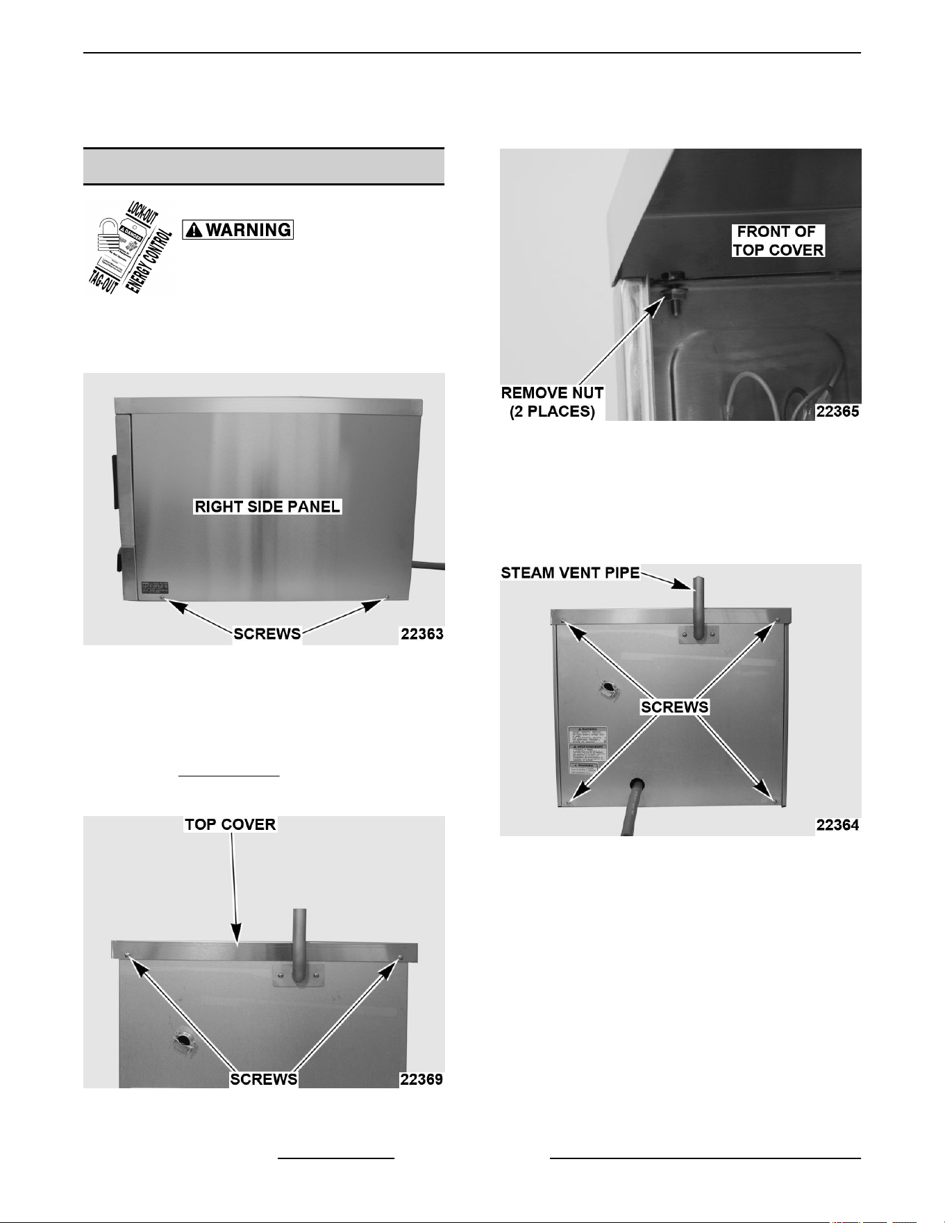
COVERS AND PANELS
Disconnect the electrical power to
the machine and follow lockout /
tagout procedures.
SIDE PANELS
1. Remove screws from bottom of panel.
Fig. 1
2. Slide panel down to clear top cover.
3. Reverse procedure to install.
TOP COVER
1. Remove SIDE PANELS.
2. Remove screws securing rear of top cover.
Fig. 2
3. Remove nuts securing front of top cover.
Fig. 3
4. Lift top cover off machine.
5. Reverse procedure to install.
REAR PANEL
1. Remove screws securing rear panel.
Fig. 4
2. Disconnect tube from steam vent pipe.
3. Remove rear panel.
4. Reverse procedure to install.
C24EO SERIES ELECTRIC COUNTERTOP STEAMERS - REMOVAL AND REPLACEMENT OF PARTS
F25386 Rev. C (1023) Page 8 of 44
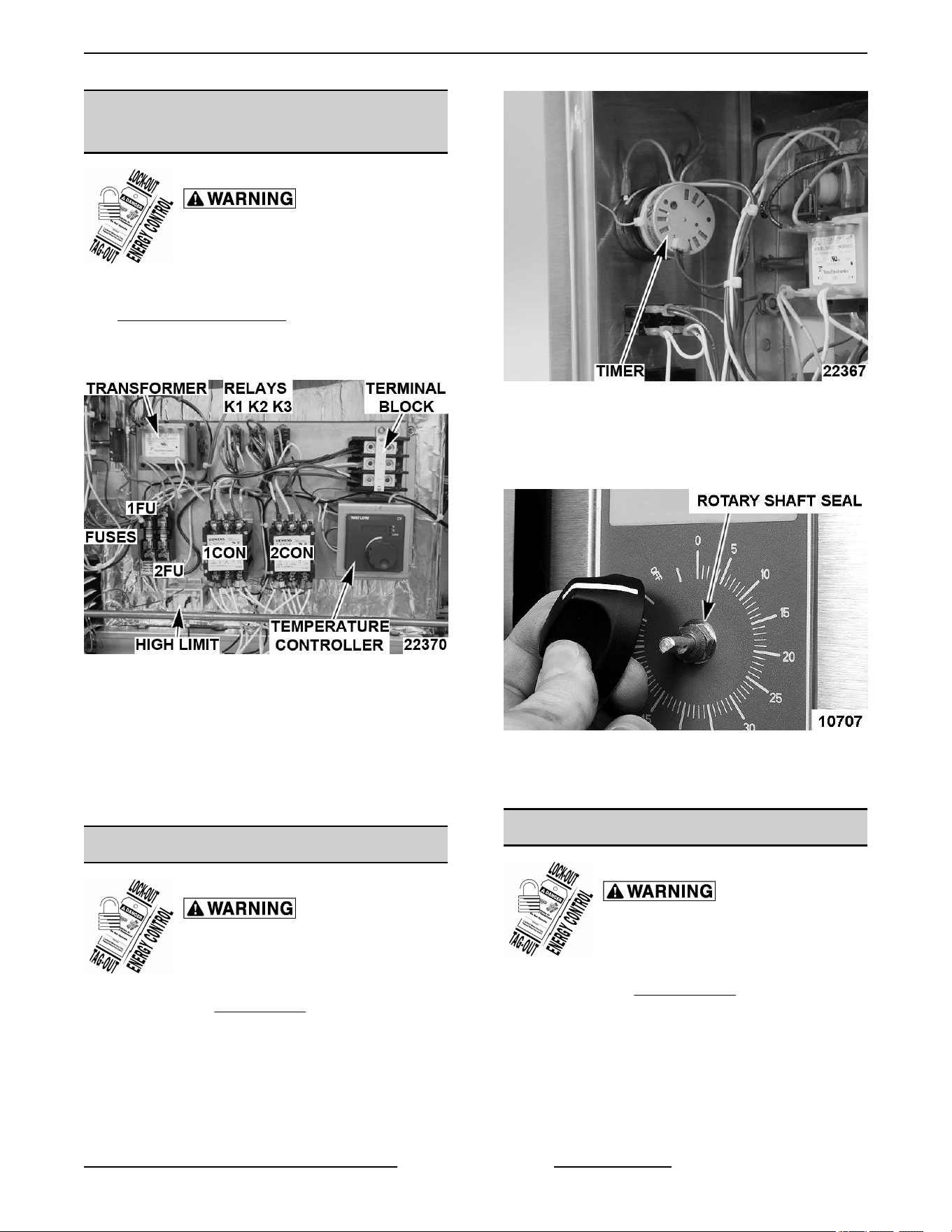
COMPONENT PANEL
COMPONENTS
Disconnect the electrical power to
the machine and follow lockout /
tagout procedures.
1. Remove right side panel as outlined under
COVERS AND PANELS.
2. Disconnect lead wires to component being
replaced.
Fig. 5
3. Remove component.
4. Reverse procedure to install replacement
component and check steamer for proper
operation.
NOTE: If replacing temperature control, see in
SERVICE PROCEDURES AND ADJUSTMENTS.
TIMER
Disconnect the electrical power to
the machine and follow lockout /
tagout procedures.
1. Remove right SIDE PANEL.
2. Disconnect lead wires to timer.
Fig. 6
3. Remove timer knob.
4. Remove rotary shaft seal from timer shaft and
remove timer.
Fig. 7
5. Reverse procedure to install and check steamer
for proper operation.
HOLD THERMOSTAT
Disconnect the electrical power to
the machine and follow lockout /
tagout procedures.
1. Remove right SIDE PANELS.
2. Remove lead wires and mounting nuts.
C24EO SERIES ELECTRIC COUNTERTOP STEAMERS - REMOVAL AND REPLACEMENT OF PARTS
Page 9 of 44 F25386 Rev. C (1023)
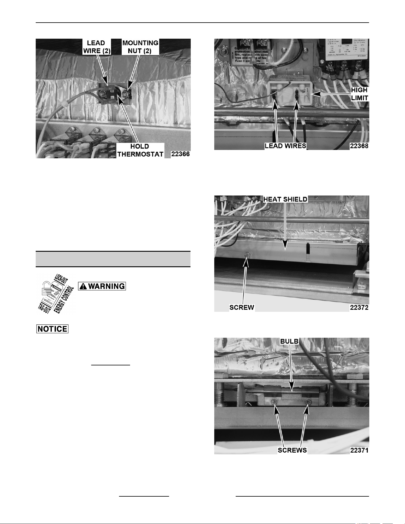
Fig. 8
3. Remove hold thermostat.
4. Apply a small amount of thermal transfer
compound to the mating surface (disk side) of the
replacement thermostat.
A. Spread the compound completely and
evenly over the surface of the thermostat.
5. Reverse procedure to install and check steamer
for proper operation.
HIGH LIMIT THERMOSTAT
Disconnect the electrical power to
the machine and follow lockout /
tagout procedures.
Do not sharply bend and kink, or clamp down on the
capillary tube or damage may occur.
1. Remove right SIDE PANEL.
2. Disconnect lead wires from high limit.
Fig. 9
3. Remove thermostat from mounting bracket.
4. Remove screw and heat shield to access
capillary bulb.
Fig. 10
5. Loosen screws securing capillary bulb.
Fig. 11
6. Remove high limit thermostat.
C24EO SERIES ELECTRIC COUNTERTOP STEAMERS - REMOVAL AND REPLACEMENT OF PARTS
F25386 Rev. C (1023) Page 10 of 44
7. Reverse procedure to install and check steamer
for proper operation.
A. Apply a small amount of thermal transfer
compound between capillary bulb and
heating element assembly.
NOTE: Do not clamp bulb with excessive force.
LOW WATER THERMOSTAT
Disconnect the electrical power to
the machine and follow lockout /
tagout procedures.
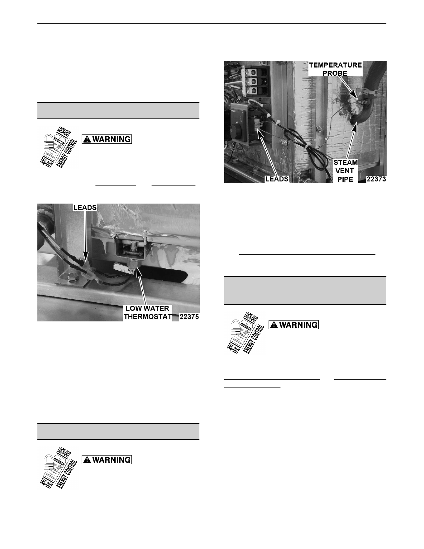
1. Remove right SIDE PANEL and REAR PANEL.
2. Disconnect lead wires.
Fig. 12
3. Remove low water thermostat.
4. Reverse procedure to install and check steamer
for proper operation.
A. Apply small amount of thermal transfer
compound to tip of thermostat.
B. Apply Loctite 242 to threads of thermostat.
C. Install thermostat hand tight. Do not over
tighten.
TEMPERATURE PROBE
Disconnect the electrical power to
the machine and follow lockout /
tagout procedures.
1. Remove right SIDE PANEL and REAR PANEL.
2. Disconnect probe leads from the temperature
control.
Fig. 13
3. Remove temperature probe from steam vent
pipe.
4. Reverse procedure to install replacement probe
and check steamer for proper operation.
5. Adjust temperature control as outlined under
TEMPERATURE CONTROL CALIBRATION in
SERVICE PROCEDURES AND
ADJUSTMENTS.
HEATING ELEMENT ASSEMBLY -
REPLACEMENT ELEMENTS
Disconnect the electrical power to
the machine and follow lockout /
tagout procedures.
NOTE: The procedures below are for Threaded Stud
Mounting of Heater Assembly and Spring Mounted
Heater Assembly (First Production).
Serial Number Cut-Off Information
Steamers with Bolt on Heating Element Assembly
• 3 pan - Serial No. 463003581 & higher.
• 5 Pan - Serial No. 463003579 & higher.
Spring Mounted Heater Assembly
• Serial No. 463003578 and lower.
Threaded Stud Mounting of Heater Assembly
NOTE: The heater contains elements that are molded
into a cast aluminum block. Block is mounted on the
underside of cooking compartment using threaded
mounting studs and hardware.
Heater Removal
C24EO SERIES ELECTRIC COUNTERTOP STEAMERS - REMOVAL AND REPLACEMENT OF PARTS
Page 11 of 44 F25386 Rev. C (1023)
1. Drain water from cavity.
2. Remove LEFT and RIGHT SIDE panels.
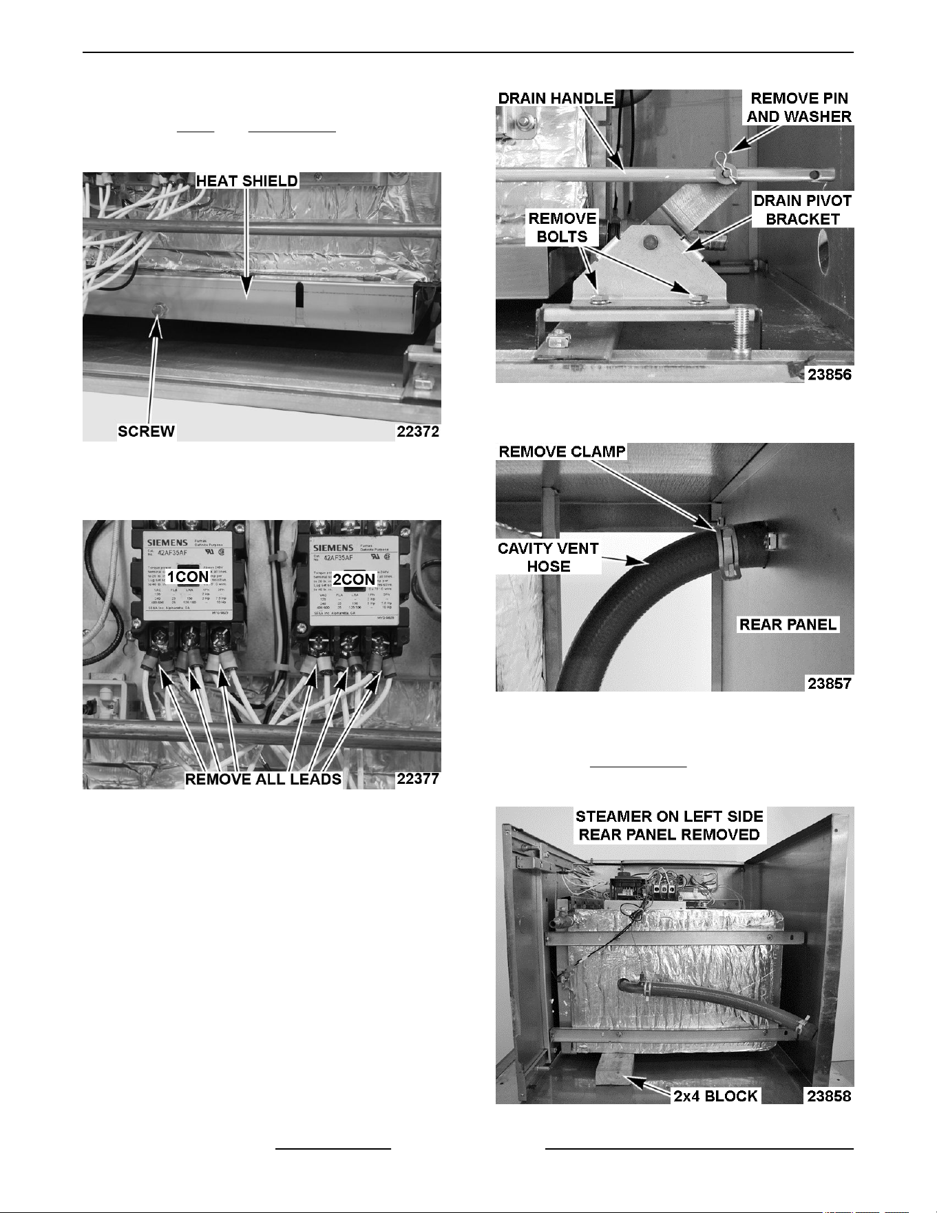
3. Remove screw and heat shield.
Fig. 14
4. Disconnect heating element leads from 1CON
and 2CON, noting their locations.
Fig. 15
5. Remove drain handle from drain lever.
6. Remove drain pivot bracket from mounting
bracket on bottom panel.
Fig. 16
7. Disconnect cavity vent hose from vent pipe.
Fig. 17
8. Place steamer on its left side (non controls side).
9. Remove REAR PANEL.
10. Place a short 2x4 block under cavity for support.
Fig. 18
C24EO SERIES ELECTRIC COUNTERTOP STEAMERS - REMOVAL AND REPLACEMENT OF PARTS
F25386 Rev. C (1023) Page 12 of 44
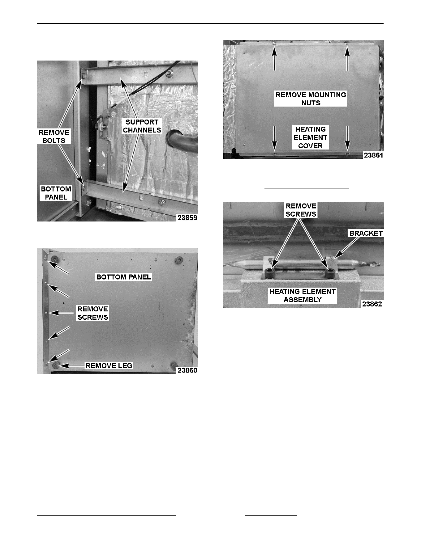
11. Remove bolts securing support channels to
bottom panel.
Fig. 19
12. Remove left front leg and bottom panel.
Fig. 20
13. Remove heating element cover.
Fig. 21
14. Remove heating element from steamer cavity.
Refer to: HIGH LIMIT THERMOSTAT. Discard all
element mounting hardware after removal.
Fig. 22
Heater Installation
NOTE: When performing heater Installation for 3 pan
unit with 240V supply, disconnect and insulate
element leads with orange, green, and red markers
(three 664W elements not used).
NOTE: Scrape off as much of the old thermal transfer
compound from underside of cooking compartment as
possible before installing replacement heater
element.
1. Completely and evenly coat contact face of
heating element assembly with thermal transfer
compound using notched trowel. Use
approximately one 13.5 oz. tube of thermal
transfer compound to cover the surface.
C24EO SERIES ELECTRIC COUNTERTOP STEAMERS - REMOVAL AND REPLACEMENT OF PARTS
Page 13 of 44 F25386 Rev. C (1023)
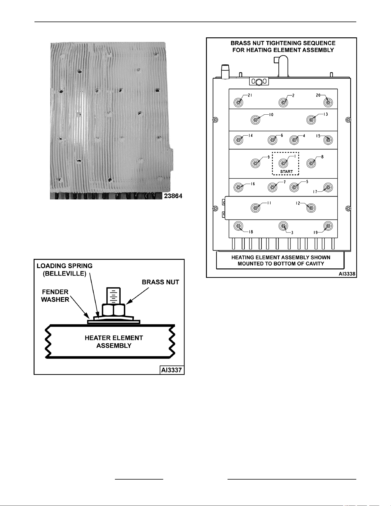
Fig. 23
2. Install heating element assembly onto bottom of
cavity.
3. Place fender washer and loading spring
(belleville) over each mounting stud. Thread
brass nut onto stud but hand tighten only.
Fig. 24
4. Torque each mounting nut in sequence shown
below to 48-52 in-lbs.
Fig. 25
5. Apply thermal transfer compound between high
limit bulb and heating element assembly.
6. Mount high limit thermostat bulb to element
assembly.
7. Install heating element cover.
8. Install bottom panel and left leg
9. Install support channels to bottom panel.
10. Install drain pivot bracket to bottom panel.
11. Install drain handle to drain lever.
12. Remove 2x4 block under the cavity.
13. Install rear panel.
14. Connect hose from vent pipe.
15. Place steamer on its legs.
16. Connect lead wires to 1CON and 2CON in noted
positions.
17. Install left and right side panels.
18. Check steamer for proper operation.
C24EO SERIES ELECTRIC COUNTERTOP STEAMERS - REMOVAL AND REPLACEMENT OF PARTS
F25386 Rev. C (1023) Page 14 of 44
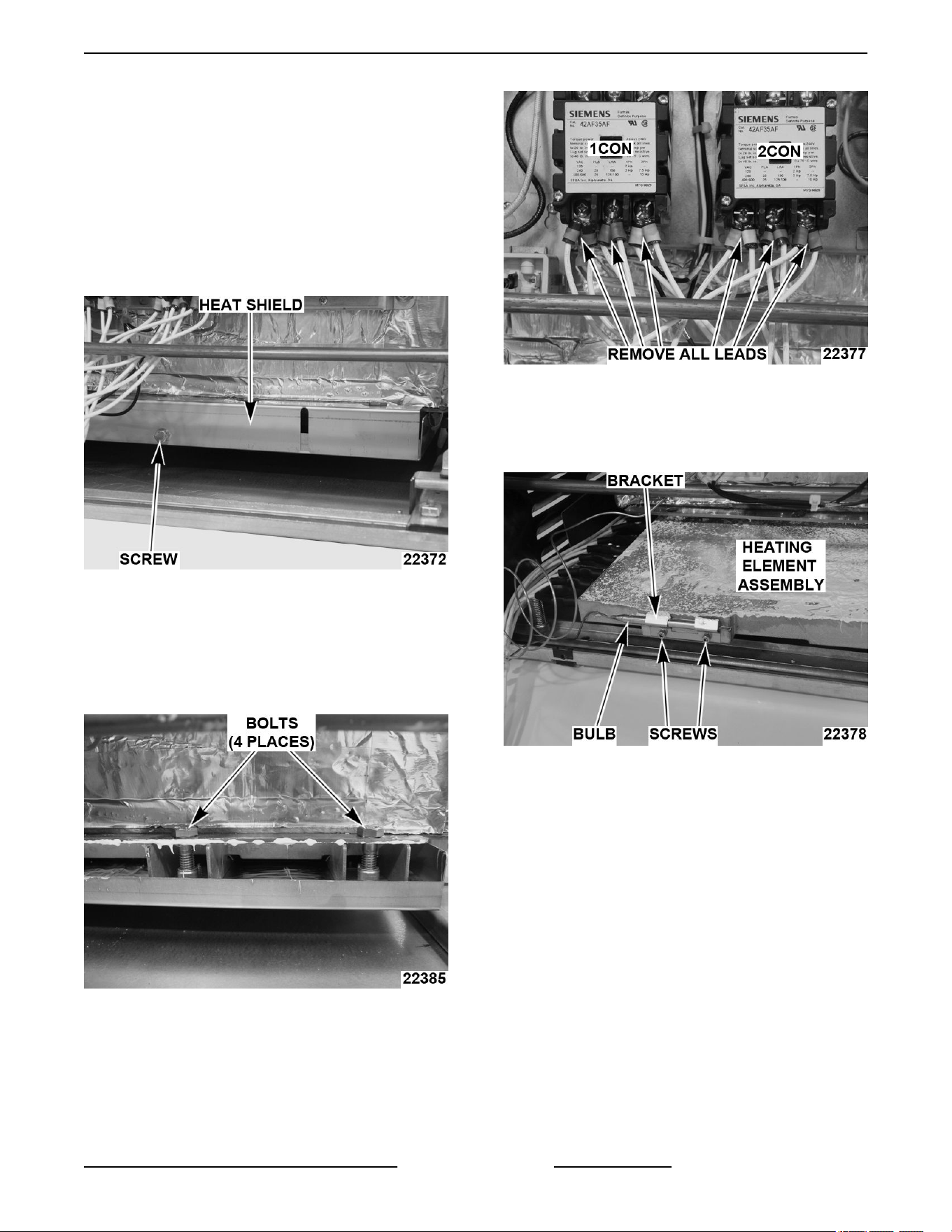
SPRING MOUNTED HEATER ASSEMBLY (First
Production)
The heater contains elements that are molded into a
cast aluminum block. The springs compress to hold
block tight to bottom surface of compartment but allow
for thermal expansion and contraction.
Heater Removal
1. Remove right side panel on steamer.
2. Remove screw and heat shield.
Fig. 26
3. Remove bolts.
NOTE: Support heater element block while removing
last bolt. Heat shield assembly (tray) is hinged on
opposite side and will tilt down after the last bolt is
removed.
Fig. 27
4. Disconnect heating element leads from 1CON
and 2CON, noting their locations.
Fig. 28
5. Partially remove heater block from heat shield
assembly (tray) by pulling assembly towards you.
6. Remove high limit thermostat bulb and bracket.
Fig. 29
7. Remove heater element block from steamer.
Heater Installation
NOTE: When performing heater Installation for 3 pan
unit with 240V supply, disconnect and insulate
element leads with orange, green, and red markers
(three 664W elements not used).
NOTE: Scrape off as much of the old thermal transfer
compound from underside of cooking compartment as
possible before installing replacement heater
element.
1. Completely and evenly coat contact face of the
replacement heater element block with heat sink
compound using notched trowel. Use
approximately one 13.5 oz. tube of thermal
transfer compound to cover the surface.
C24EO SERIES ELECTRIC COUNTERTOP STEAMERS - REMOVAL AND REPLACEMENT OF PARTS
Page 15 of 44 F25386 Rev. C (1023)
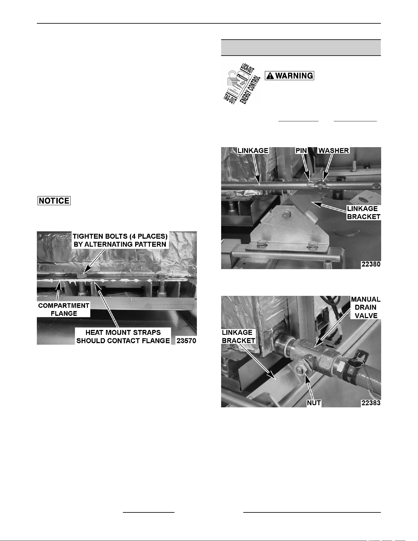
2. Slide heater element block partially into heat
shield assembly (tray), leaving enough space to
mount high limit bulb.
A. Apply heat sink compound between high
limit bulb and heater element block.
B. Secure high limit thermostat bulb to the
heater element block.
3. Slide heater block in until it stops then push
toward front of machine.
A. Raise heat shield assembly (tray) and install
mounting bolts to secure. Hand tighten only.
B. Tighten one of the inner bolts several turns
then move to other inner bolt. Continue
tightening all 4 bolts in an alternating pattern
until top of each heat mount strap contacts
bottom of cooking compartment flange.
Do not over tighten bolts or damage to heat mount
strap may occur.
Fig. 30
C. Ensure heat sink compound does not flow
onto low water thermostat (sensor) at rear
of compartment. If it does, remove excess.
4. Connect lead wires to 1CON and 2CON in noted
positions. Tighten screws to secure wires.
5. Install heat shield.
6. Check steamer for proper operation.
MANUAL DRAIN VALVE
Disconnect the electrical power to
the machine and follow lockout /
tagout procedures.
1. Remove right SIDE PANEL and REAR PANEL.
2. Remove pin and washer to disconnect the handle
linkage from linkage bracket.
Fig. 31
3. Remove nut and linkage bracket.
Fig. 32
4. Remove drain valve.
5. Reassemble parts removed in reverse order of
removal.
A. Apply pipe thread sealant to plumbing
threads before assembly.
6. Check steamer for leaks and proper operation.
C24EO SERIES ELECTRIC COUNTERTOP STEAMERS - REMOVAL AND REPLACEMENT OF PARTS
F25386 Rev. C (1023) Page 16 of 44
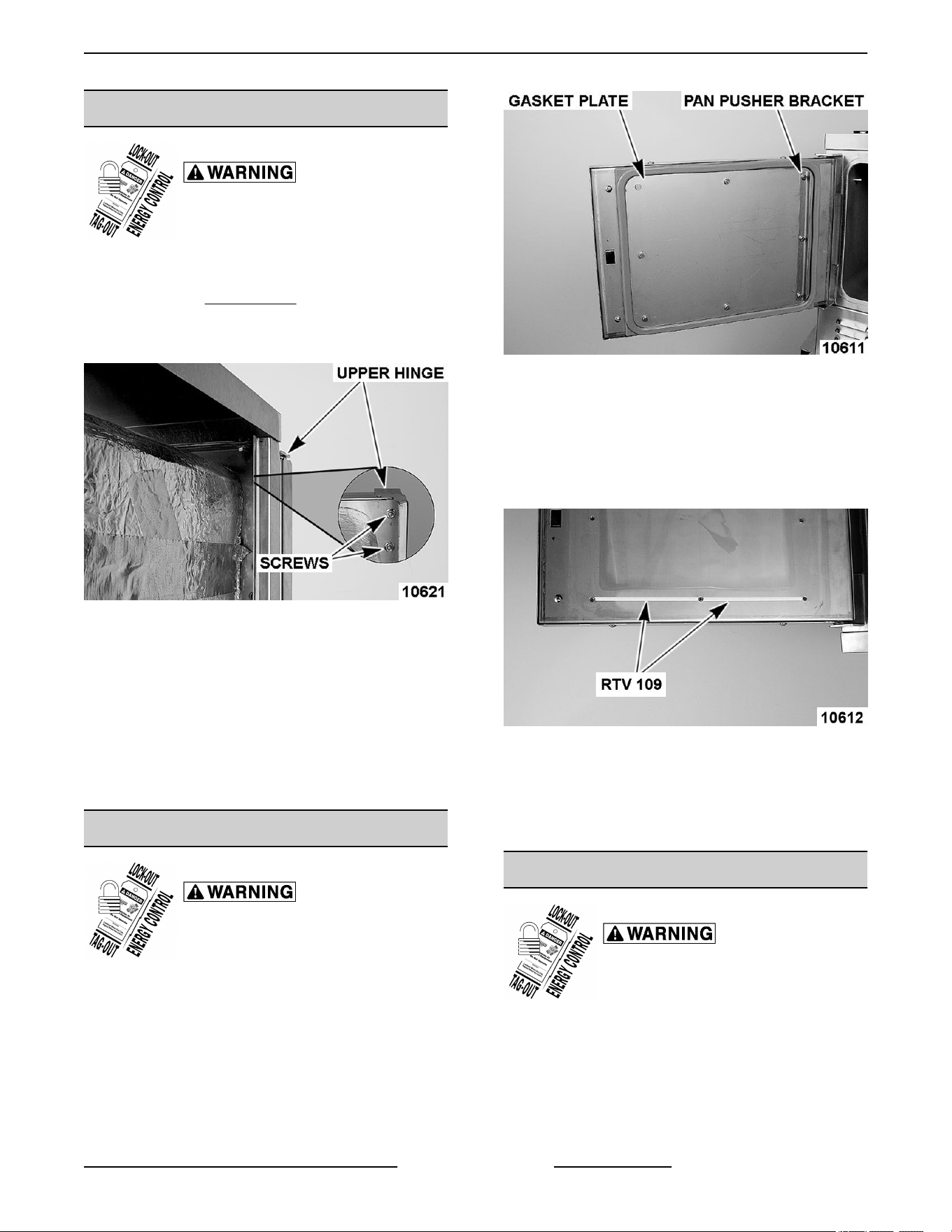
DOOR
Disconnect the electrical power to
the machine and follow lockout /
tagout procedures.
1. Close door.
2. Remove left SIDE PANEL.
3. Remove nuts from upper hinge located inside
front panel.
Fig. 33
4. Open door slightly, and while holding door, pull
upper hinge away from front panel.
5. Pull upper hinge out of upper door hinge bushing.
6. Lift door assembly up and off lower door hinge.
7. Reinstall parts removed in reverse order of
removal.
8. Check door for fit and proper sealing of gasket.
DOOR GASKET
Disconnect the electrical power to
the machine and follow lockout /
tagout procedures.
1. Open door.
2. Remove the shoulder screws and pan pusher
bracket from gasket plate.
Fig. 34
3. Remove gasket plate.
4. Remove gasket from inner door panel.
5. Remove RTV from bottom part of inner door
panel. Apply new RTV 109 to bottom of door
where shown when assembling gasket to door.
Fig. 35
6. Place a small amount of RTV109 into the inner
door panel gasket screw holes before assembly.
7. Position the new gasket on gasket plate and
reverse procedure to install.
DOOR HANDLE
Disconnect the electrical power to
the machine and follow lockout /
tagout procedures.
REMOVAL
1. Open door.
2. Remove screws from top and bottom of door
assembly.
C24EO SERIES ELECTRIC COUNTERTOP STEAMERS - REMOVAL AND REPLACEMENT OF PARTS
Page 17 of 44 F25386 Rev. C (1023)
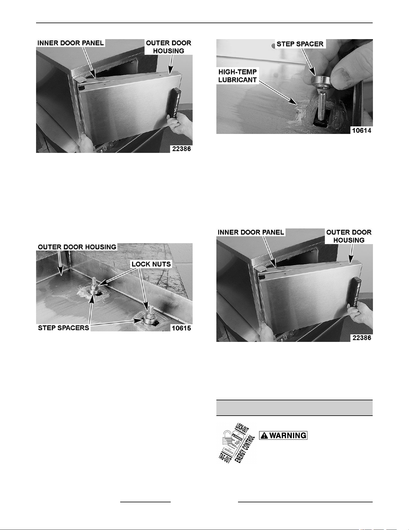
Fig. 36
3. Pull outer door housing away from inner door
panel starting at the hinge side of door to
separate the door halves.
NOTE: The smaller radius of the step spacers fit into
the slots of the outer door housing and is used to
provide clearance for handle operation.
4. Remove lock nuts and stepped spacers from
threaded studs of door handle.
Fig. 37
INSTALLATION
1. Apply Lubriplate 630AA around slots of outer
door housing where step spacers contact
housing.
2. Install door handle into outer door housing such
that hinge side of door housing is to the left and
arrow on handle is pointed upward.
3. Install step spacer with smaller radius toward
handle and door housing. Smaller radius is a slip
fit with outer door housing slot.
Fig. 38
4. Install lock nuts and tighten until no gap exists
between handle, step spacer and lock nut. Do not
over-tighten lock nuts.
5. Close inner door panel so that latch mechanism
engages striker on front panel.
6. Install outer door housing onto inner door panel.
7. Align the top and bottom screw holes of outer
door housing with inner door panel.
Fig. 39
8. Apply Loctite 7471 Primer N and Loctite 242 to
threads of screws before assembling.
9. Install screws to secure door halves together.
10. Check opening and closing operation of door.
DOOR LATCH ASSEMBLY
Disconnect the electrical power to
the machine and follow lockout /
tagout procedures.
REMOVAL AND DISASSEMBLY
C24EO SERIES ELECTRIC COUNTERTOP STEAMERS - REMOVAL AND REPLACEMENT OF PARTS
F25386 Rev. C (1023) Page 18 of 44
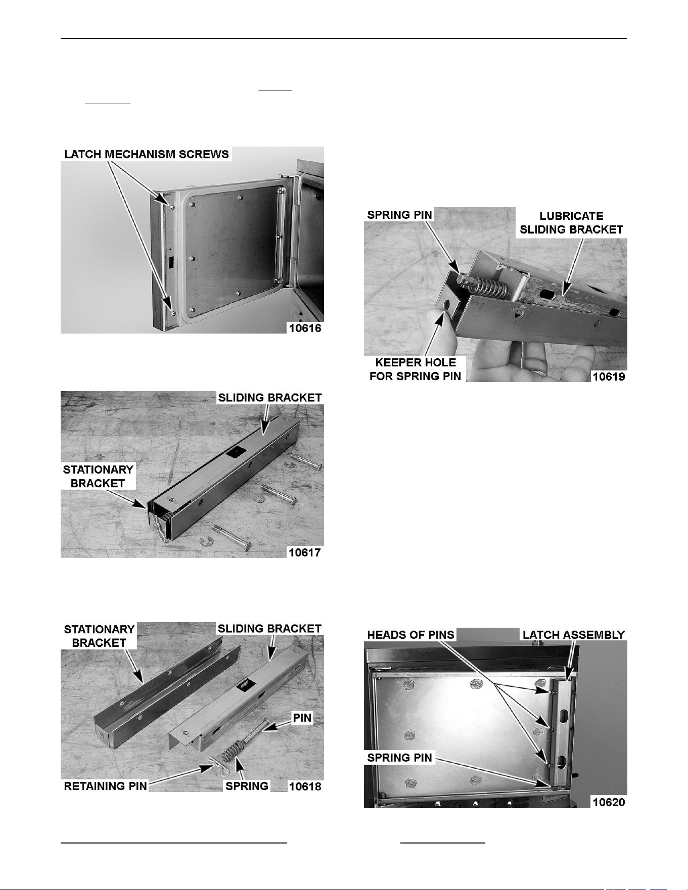
1. Separate outer door housing assembly from
inner door panel as outlined under DOOR
HANDLE.
2. Remove screws securing latch assembly to inner
door panel and remove latch mechanism.
Fig. 40
3. Remove E-clip from latch assembly pins and pull
pins from latch mechanism.
Fig. 41
4. Remove retaining pin from spring pin.
5. Separate sliding bracket from stationary bracket.
Fig. 42
ASSEMBLY
1. Apply Lubriplate 630AA to sides of sliding
bracket.
2. Insert spring pin into bottom of sliding bracket.
A. Place spring over spring pin.
3. Assemble sliding bracket into stationary bracket.
4. While holding head of spring pin against bottom
of sliding bracket, insert spring pin into keeper
hole in bottom of stationary bracket.
Fig. 43
A. Secure spring pin in place with retaining pin.
NOTE: Install pins such that heads of pins will be
facing inward toward hinge side of inner door panel
when latch assembly is installed.
5. Install pins to assemble stationary and sliding
brackets together.
A. Secure pins into position with E-clip.
INSTALLATION
1. Install latch assembly onto inner door panel with
spring pin toward bottom of door panel.
A. Apply Loctite 271 to threads of screws
before assembly and secure latch assembly
to inner door panel.
Fig. 44
C24EO SERIES ELECTRIC COUNTERTOP STEAMERS - REMOVAL AND REPLACEMENT OF PARTS
Page 19 of 44 F25386 Rev. C (1023)
2. Install outer door housing assembly as outlined
in DOOR HANDLE INSTALLATION.
3. Check opening and closing operation of door.
4. Check steamer for proper operation and leaks
around door seal.
DOOR HINGE BEARINGS
Disconnect the electrical power to
the machine and follow lockout /
tagout procedures.
1. Close door.
2. Remove left side panel, see COVERS AND
PANELS.
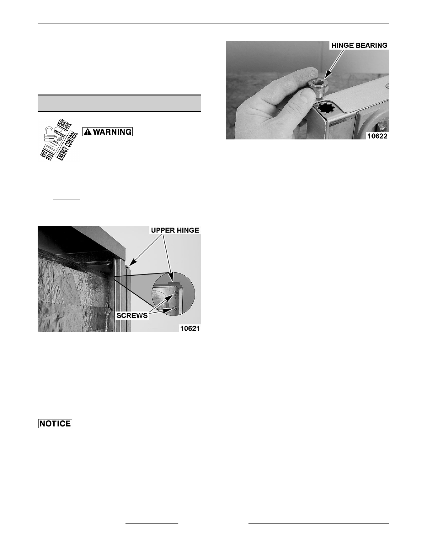
3. Remove nuts from upper hinge located inside
front panel.
Fig. 45
4. Open door slightly, and while holding door, pull
upper hinge away from front panel.
5. Pull upper hinge out of upper door hinge bearing.
6. Lift door assembly up and off lower door hinge.
7. Pry hinge bearing out from door assembly.
8. Remove outer door housing.
Do not drive bearing into place. The inner door panel
could be damaged. Press bearing into position.
NOTE: When replacing door hinge bearings, replace
both hinge bearings.
9. Position replacement hinge bearing over hinge
opening in door assembly.
Fig. 46
A. Press hinge bearing fully into door assembly
using a C-clamp or equivalent.
10. Reassemble parts removed in reverse order.
11. Check door for fit and proper door gasket sealing.
C24EO SERIES ELECTRIC COUNTERTOP STEAMERS - REMOVAL AND REPLACEMENT OF PARTS
F25386 Rev. C (1023) Page 20 of 44
REMOVAL AND REPLACEMENT (AUTOFILL
OPTIONAL)
PROBES
Disconnect the electrical power to
the machine and follow lockout /
tagout procedures.
1. Shut off electric and water supply.
2. Remove RIGHT SIDE PANEL to access probes
behind steamer cavity.
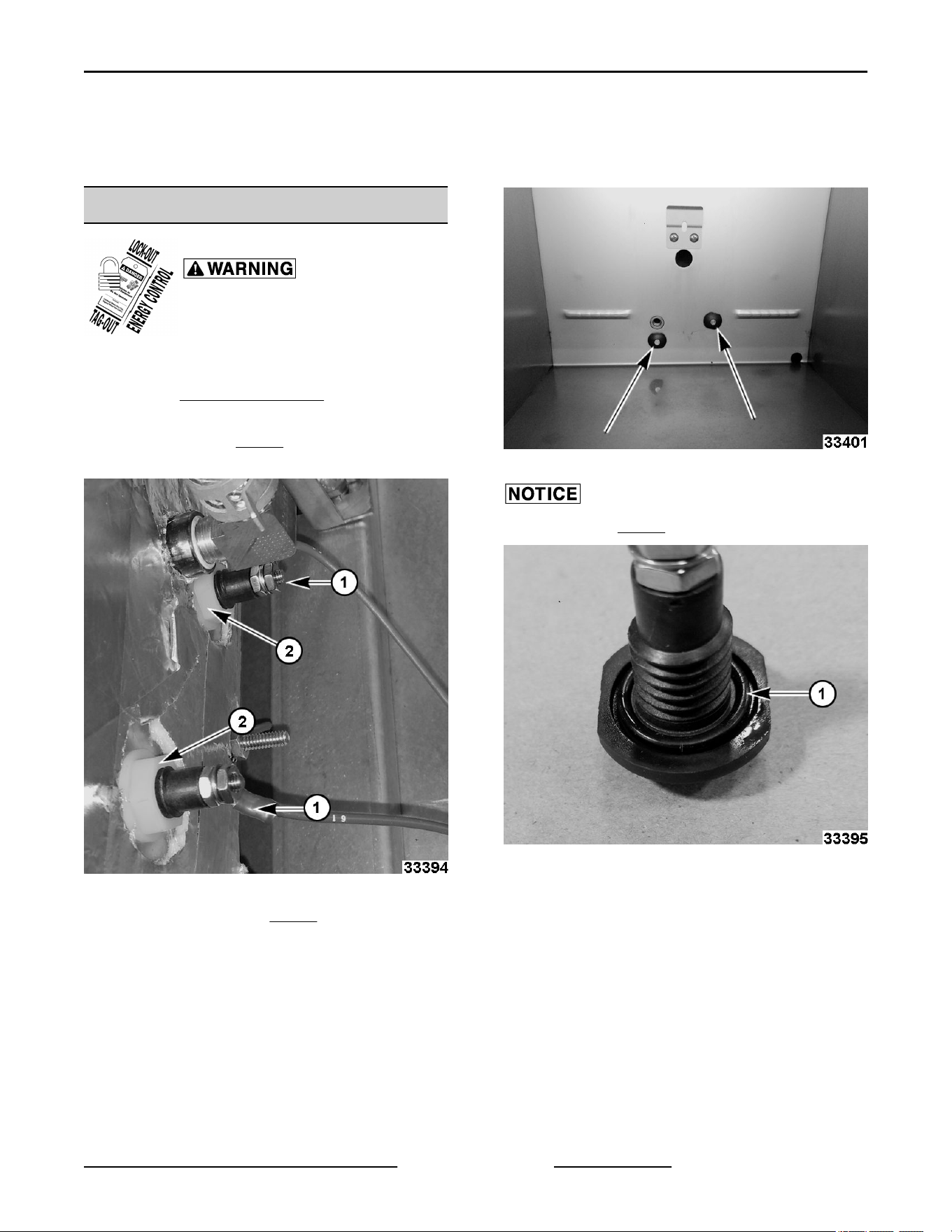
3. Remove nuts (1, Fig. 47) holding wire terminals
on probes.
Fig. 47
4. Remove nylon nut (2, Fig. 47) on back of probe.
5. Remove probe from inside steamer cavity.
Fig. 48
Verify O-ring (1, Fig. 49) is seated and not damaged.
Fig. 49
6. Reverse procedure to install.
C24EO SERIES ELECTRIC COUNTERTOP STEAMERS - REMOVAL AND REPLACEMENT (AUTOFILL
OPTIONAL)
Page 21 of 44 F25386 Rev. C (1023)
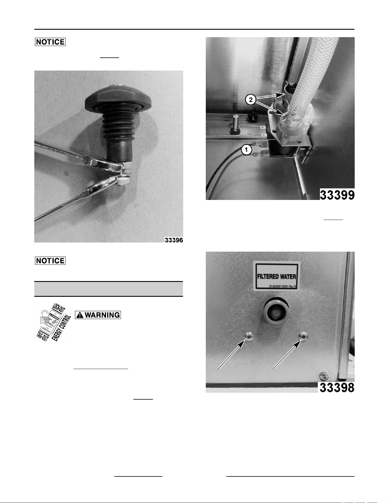
Use a back-up wrench (Fig. 50) to keep internal probe
components from twisting when reinstalling.
Fig. 50
Do not overtighten nylon nut.
SOLENOID VALVES
Disconnect the electrical power to
the machine and follow lockout /
tagout procedures.
1. Shut off electric and water supply.
2. Remove LEFT SIDE PANEL.
NOTE: If left side is not accessible, solenoid valves
can be accessed through the right side.
3. Note and disconnect wires (1, Fig. 51).
Fig. 51
4. Disconnect hose and cap clamps (2, Fig. 51)
from outlet ports.
5. Remove solenoid mounting screws from back of
unit.
Fig. 52
6. Reverse procedure to install.
7. Use new clamps when installing cap and hose on
outlet ports.
C24EO SERIES ELECTRIC COUNTERTOP STEAMERS - REMOVAL AND REPLACEMENT (AUTOFILL
OPTIONAL)
F25386 Rev. C (1023) Page 22 of 44
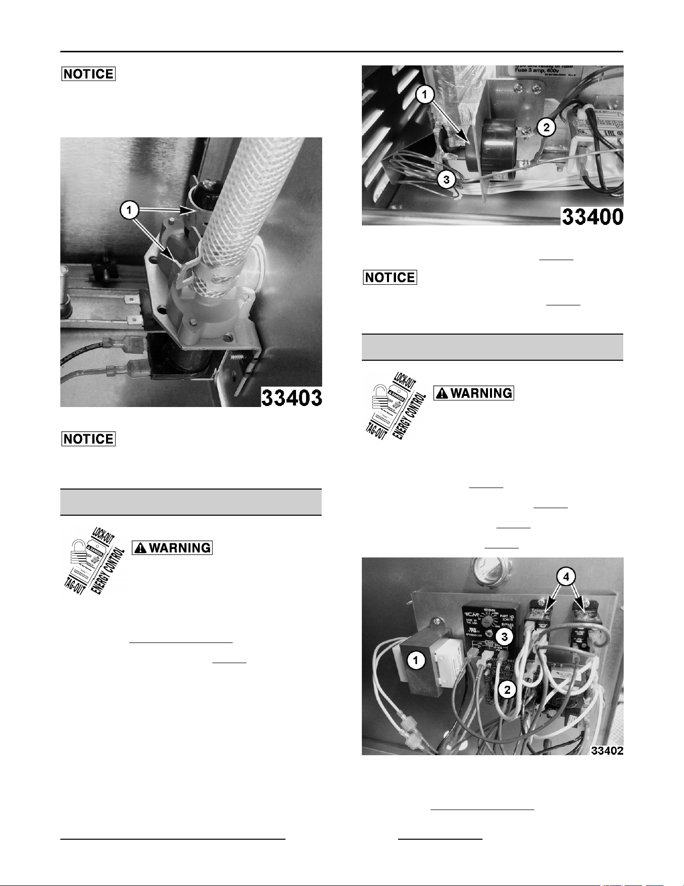
Apply two to three wraps of electrical tape on valve
where the hose clamp seats during installation to help
prevent leaks.
Fig. 53
Verify cap and clamp are installed on outlet port not
being used.
WATER LEVEL ALARM
Disconnect the electrical power to
the machine and follow lockout /
tagout procedures.
1. Shut off electric and water supply.
2. Remove RIGHT SIDE PANEL.
3. Remove knurled knob (1, Fig. 54).
Fig. 54
4. Note and disconnect wiring (2, Fig. 54).
Take care not bend capillary tube (3, Fig. 54).
5. Reverse procedure to install.
AUTOFILL CONTROL ASSEMBLY
Disconnect the electrical power to
the machine and follow lockout /
tagout procedures.
Components on the Autofill control assembly are:
• Transformer. (1, Fig. 55)
• Low Water Control Board. (2, Fig. 55)
• Time Delay Relay. (3, Fig. 55)
• Relay Switches. (4, Fig. 55)
Fig. 55
1. Shut off electric and water supply.
2. Remove RIGHT SIDE PANEL.
C24EO SERIES ELECTRIC COUNTERTOP STEAMERS - REMOVAL AND REPLACEMENT (AUTOFILL
OPTIONAL)
Page 23 of 44 F25386 Rev. C (1023)
3. Note and disconnect wiring from component
being replaced.
4. Remove component mounting screws.
5. Reverse procedure to install.
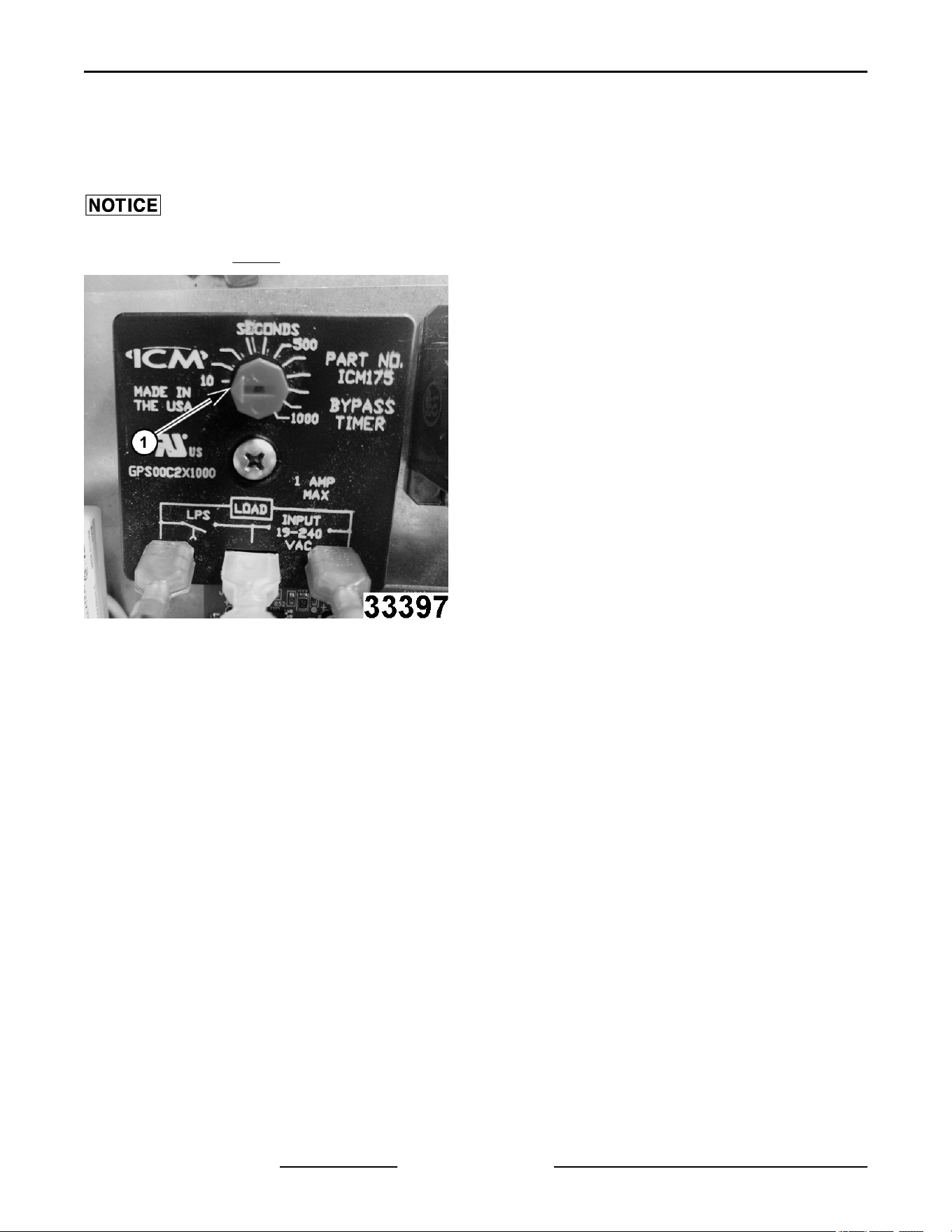
When replacing time delay relay, verify seconds are
set at 10 seconds (1, Fig. 56).
Fig. 56
C24EO SERIES ELECTRIC COUNTERTOP STEAMERS - REMOVAL AND REPLACEMENT (AUTOFILL
OPTIONAL)
F25386 Rev. C (1023) Page 24 of 44
SERVICE PROCEDURES AND ADJUSTMENTS
Certain procedures in this section require electrical test or measurements while power is applied to the
machine. Exercise extreme caution at all times. If test points are not easily accessible, disconnect power
and follow lockout / tagout procedures, attach test equipment and reapply power to the test.
DOOR LATCH ADJUSTMENT
Opening a Jammed Door
Should the steamer door jam and cannot be opened,
DO NOT FORCE OR PRY the door as damage will
occur.
1. Lift up on bottom of door at the handle end to
disengage latch.
A. If door does not open, remove right side
panel, see COVERS AND PANELS .
B. Locate the striker that catches on door latch
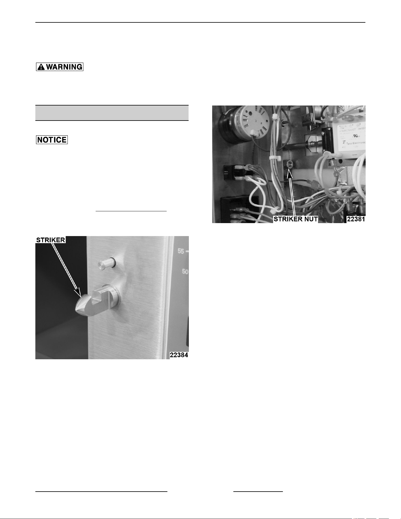
near steam chamber on front panel.
Fig. 57
C. Remove nut from striker and this should
release it from the panel.
Fig. 58
D. Open door.
2. Remove striker.
3. Remove any burrs on striker that may cause latch
to stick.
4. Apply Loctite 271 to threads of striker.
5. Reinstall striker with slotted side up. Snug striker
nut. Perform Adjustment, so door will not jam.
Adjustment
1. Reinstall striker with slot pointing upward and
hand tighten nut only.
2. Close door to center striker in front panel
mounting hole.
3. Open door and check striker slot for horizontal
alignment. The slot on striker must be kept
horizontal in order for door latch to catch properly
and latch.
4. Once proper slot alignment has been set, hold
striker close to its base then tighten the striker
nut. Be careful not to damage striker slot when
tightening or door may not latch properly.
NOTE: Do not over-tighten nut. If over-tightened,
striker may turn and change alignment.
NOTE: If door does not open easily, add shims
between striker and cabinet front. When adding shims
make certain that door gasket seals properly and
C24EO SERIES ELECTRIC COUNTERTOP STEAMERS - SERVICE PROCEDURES AND ADJUSTMENTS
Page 25 of 44 F25386 Rev. C (1023)
steamer does not leak. Remove shims as necessary
until leaking stops.
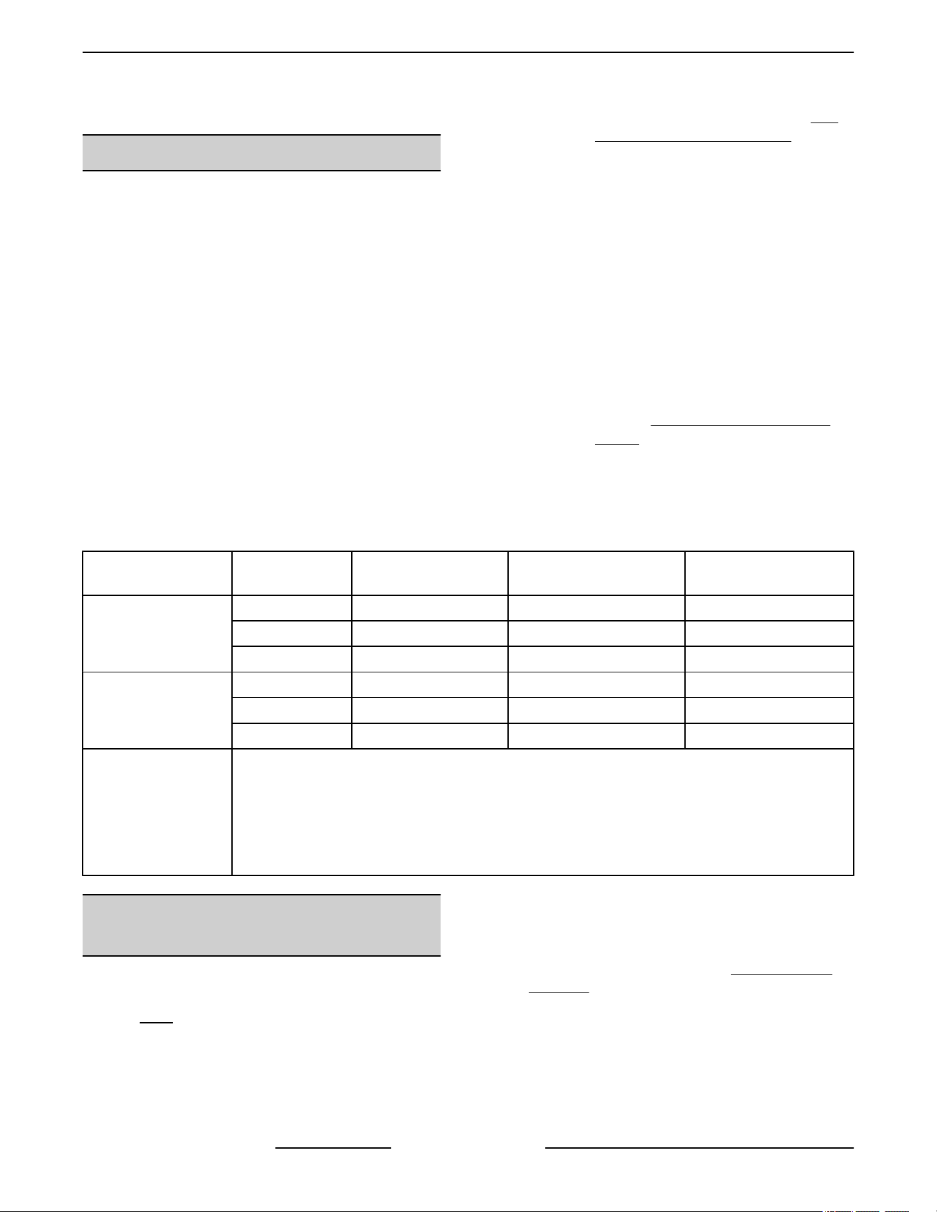
HEATING ELEMENT TEST
The heating element assembly contains elements
molded into a cast aluminum block. 3 pan units have
6 elements and 5 pan units have 3 elements. See
wiring diagrams.
1. Turn cooking mode switch to constant.
2. Measure voltage at heating element terminals on
contactors and verify it against data plate
voltage.
NOTE: For 480V units, element voltage is 277V.
A. If voltage is incorrect, find the source of the
problem.
B. If voltage is correct, check current draw
(amps) through the heating element lead
wires.
NOTE: This method is preferred over a resistance
check when a clamp on type amp meter is available.
1) If current draw is correct then heating
element is functioning properly. See
table below for proper values.
2) If current draw is not correct, turn
cooking mode switch to OFF and
disconnect the electrical supply.
a. Replace heating element
assembly then proceed to step 3.
C. If unable to check current draw, a resistance
check may indicate a malfunctioning
element.
1) Turn the cooking mode switch to OFF
and disconnect the electrical supply.
2) Remove the lead wires from the
heating element and check resistance
(ohms). See table below for proper
values
3. Check for proper operation.
MODEL VOLTS
WATTS PER
ELEMENT
AMPS PER ELEMENT
LEAD
OHMS PER ELEMENT
C24EO3
208 2003 9.6 21.6
208 664 3.2 65.2
240 2667 11.1 21.6
C24EO5
208 4000 19.2 10.8
240 4000 16.7 14.4
480 4000 14.4 19.2
NOTES:
1. Values in the table are nominal. Tolerance is +5/-10%.
2. 3 pan 208V units use three 2003W elements and three 664W elements.
3. 3 pan 208/240V units share the same element assembly block. 240V units use only the
three 2003W-marked elements (2667W actual).
4. Resistance values
TEMPERATURE CONTROL
CALIBRATION
To set temperature control for optimum steamer
operation, the elevation above sea level for service
location must first be determined. The steamer was
preset at factory to sea level.
The elevation is used in conjunction with elevation
table below, to determine correct set point
temperature for the control.
NOTE: If set point temperature is too high, the excess
boiling action will cause water droplets to exit the
steam vent pipe, and cause high water usage.
1. Remove right side panel, see COVERS AND
PANELS.
2. Place a thermocouple approximately one inch
down in the center of steam vent pipe.
3. Turn steamer on by selecting constant mode.
4. Allow steamer temperature to stabilize by
completing two heating cycles.
C24EO SERIES ELECTRIC COUNTERTOP STEAMERS - SERVICE PROCEDURES AND ADJUSTMENTS
F25386 Rev. C (1023) Page 26 of 44
5. Record the temperature reading when regulating
contactor opens.
6. Using the elevation table, compare the recorded
temperature to the temperature listed for the
specific elevation.
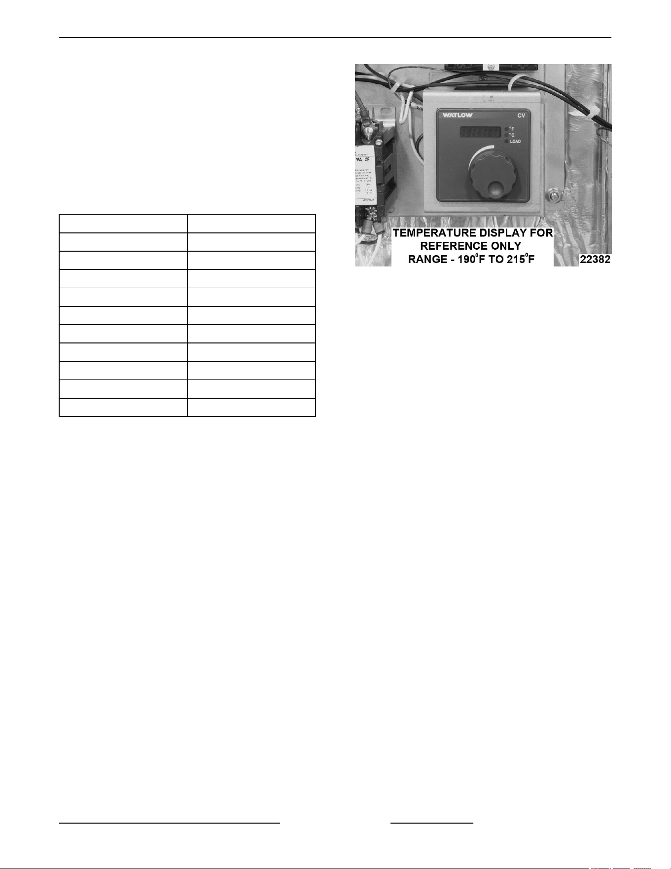
NOTE: Use temperature scale on control dial plate for
reference only. The scale represents dial turns in 1°F
increments, not the actual temperature. When
calibrating, use the recorded temperature taken from
thermocouple.
ELEVATION (FT) TEMPERATURE (°F)
Sea Level 210
1,000 208
2,000 206
3,000 204
4,000 202
5,000 200
6,000 198
7,000 196
8,000 195
9,000 or above 194
A. If the set point temperature of the control is
correct, no adjustment is necessary.
B. If the set point temperature of the control is
not correct, adjust the temperature control.
1) Turn temperature control dial
clockwise to increase temperature or
counterclockwise to decrease
temperature.
NOTE: During temperature control adjustment,
display will blink on/off. When display reverts to a
steady image, that displayed temperature set point
has been "locked in" to memory.
Fig. 59
C24EO SERIES ELECTRIC COUNTERTOP STEAMERS - SERVICE PROCEDURES AND ADJUSTMENTS
Page 27 of 44 F25386 Rev. C (1023)
ELECTRICAL OPERATION
COMPONENT FUNCTION
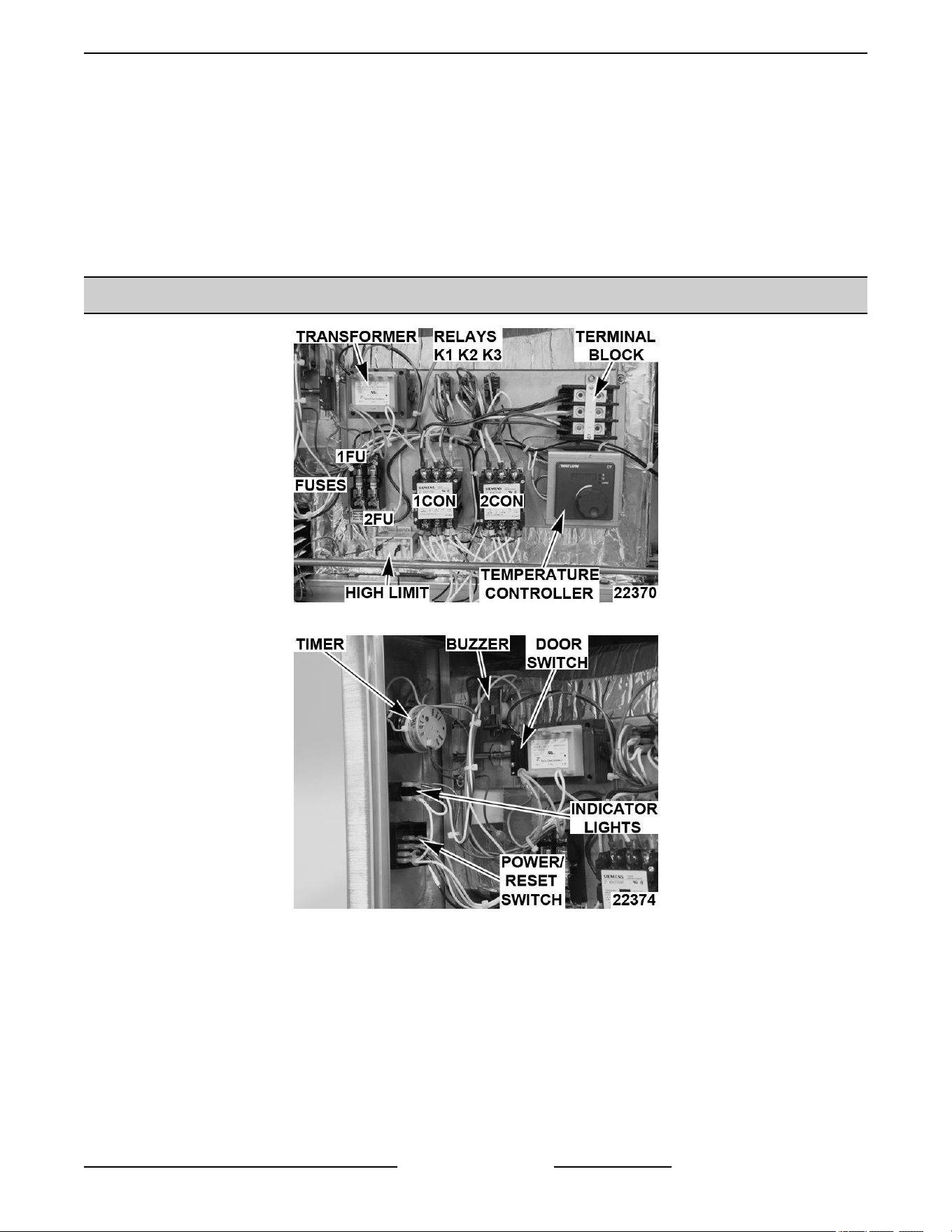
Buzzer ................ Creates audible signal when timed cook cycle is complete and when a low water condition
exists.
Limiting Contactor
(1CON) ................
Supplies line voltage to heating element assembly. Energized whenever Power Switch
(1S) is on and High Limit Thermostat (1TAS) and Low Water Thermostat (2TAS) are
closed.
Regulating Contactor
(2CON) ................
Supplies line voltage to heating element assembly. Energized whenever Hold
Thermostat (3TAS) is closed or the temperature controller calls for heat.
Heating Element ...... Located below water reservoir. Heats water to produce steam.
Fuses (1FU & 2FU) .... Protect control circuitry from over-currents.
Low Water Light
(1LT) ..................
Amber (AM) colored light. Lit when Low Water Thermostat (2TAS) senses water level is
too low inside steamer.
On Light (2LT) ........ Amber (AM) colored light. Lit when Power Switch (1S) is on.
Cook Light (3LT) ...... Red (RD) colored light. Lit when High Limit (1TAS) and Low Water (2TAS) thermostats
are closed, door is closed and timer is set.
Relay (K1) ............ Controls Regulating Contactor (2CON) based on input from Hold Thermostat (3TAS) and
Temperature Controller. Does not allow Timer Motor to run while Hold Thermostat (3TAS)
is closed.
Relay (K2) ............ Latches Power Switch (1S) circuit. Turns on Low Water Light (1LT) and Buzzer when
steamer is low on water.
Relay (K3) ............ Controlled by Power Switch (1S). Keeps Buzzer from sounding and Low Water Light
(1LT) off when switch is in off position.
Power Switch (1S) .... Rocker switch that turns steamer OFF and ON (momentary on). Switch also resets Low
Water Light (1LT) and Buzzer.
Door Switch (1SW) ... Removes power from a portion of the steamer control circuit when door is opened.
High Limit Thermostat
(1TAS) ................
Protects steamer by removing control circuit power if the heating element assembly
temperature goes above 495°F.
Low Water Thermostat
(2TAS) ................
Monitors presence of water inside steamer.
Hold Thermostat
(3TAS) ................
Controls temperature of cavity for pre-heat/hold mode (opens at 175°F). Disables timer
countdown if cavity temperature is too low.
Timer Motor .......... Counts cook time of product when time is dialed. Energizes buzzer and de-energizes
temperature controller when time expires.
Temperature
Control ...............
Monitors temperature probe and cycles power to regulating contactor (2 CON) for steam
generation.
Temperature Probe ... Senses cooking compartment temperature at steam vent and sends a corresponding DC
voltage back to the temperature control (J-type thermocouple).
Transformer (1T) ..... Steps down line voltage to 120 VAC control circuit voltage.
........................ Autofill Components (Optional)
Button Probes ........ Senses minimal and maximum water levels in steamer.
C24EO SERIES ELECTRIC COUNTERTOP STEAMERS - ELECTRICAL OPERATION
F25386 Rev. C (1023) Page 28 of 44
Fill Solenoid
Valves ................
Used to regulate water flow.
Water Level Alarm
(Buzzer) ...............
Creates audible signal when water reaches maximum level.
Transformer .......... Lowers water level alarm to 24V.
Low Water Control
Board .................
Monitors button probes to keep water level maintained.
COMPONENT LOCATION
Fig. 60
Fig. 61
C24EO SERIES ELECTRIC COUNTERTOP STEAMERS - ELECTRICAL OPERATION
Page 29 of 44 F25386 Rev. C (1023)
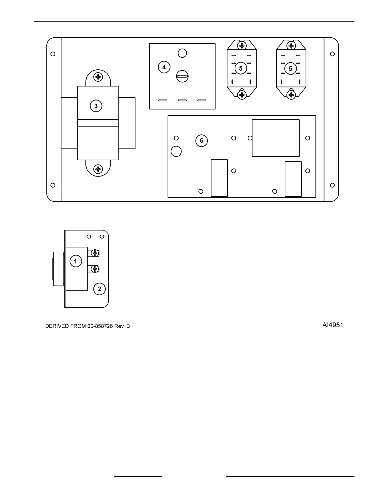
Fig. 62
C24EO SERIES ELECTRIC COUNTERTOP STEAMERS - ELECTRICAL OPERATION
F25386 Rev. C (1023) Page 30 of 44
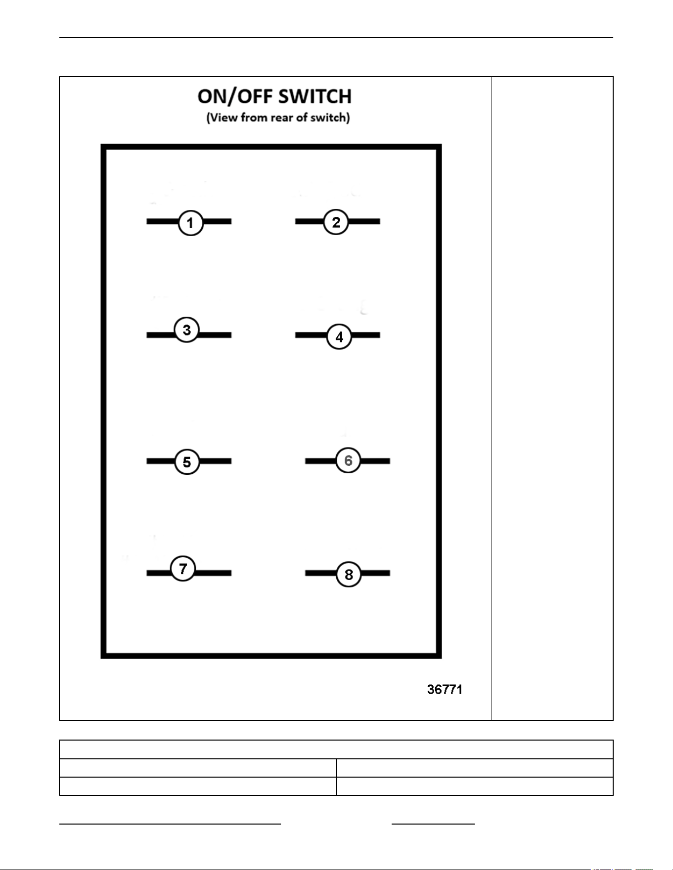
Fig. 63
1. Blank
2. #7 Red
3. #5 Gray
4. #3 Orange
5. #6 Black
6. Blank
7. #4 White
8. #4 White
AUTOFILL COMPONENTS
COMPONENT CALLOUT # DESCRIPTION
1 Water Level Alarm (Buzzer)
C24EO SERIES ELECTRIC COUNTERTOP STEAMERS - ELECTRICAL OPERATION
Page 31 of 44 F25386 Rev. C (1023)
AUTOFILL COMPONENTS
COMPONENT CALLOUT # DESCRIPTION
2
Water Level Alarm (Buzzer) Bracket
NOTE: Located under the right side panel, toward front
of unit.
3 Transformer
4 Time Delay Relay
5
Relay Switches
NOTE: Relay switches are connected to overfill light.
When replacing relays verify overfill light is operating.
6 Low Water Control Board
NOTE: Autofill is optional. Control board assembly is located under the right side panel and mounted to inside of
the back panel.
SEQUENCE OF OPERATION
SCHEMATIC DIAGRAM AI2851 will be used to
explain the electrical sequence of operation.
Timed Cooking Mode
1. Conditions.
A. Steamer connected to correct voltage and is
properly grounded.
B. Power switch (1S) off.
1) Relay K3 energized. K3 N.C. contacts
open.
C. High limit thermostat closed.
D. Hold thermostat closed.
E. Low water thermostat closed.
F. Temperature control is setup properly and is
ready to use.
G. Door closed (door switch closed).
H. Timer off.
I. Cooking compartment filled to the water
level mark and below hold temperature of
175°F (+/- 5°F).
J. Drain valve is closed (drain lever pushed in).
2. Press momentary start switch (1S).
A. Limiting contactor (1CON) coil energized
thru high limit thermostat (1TAS).
1) Line voltage is supplied to one side of
heating elements.
B. Relay K2 coil energized thru low water
thermostat (2TAS).
1) K2-1 N.O. contacts close.
a. Power switch circuit is latched.
2) K2-2 N.C. contacts open.
a. Low water light (1LT) and buzzer
are de-energized.
C. ON indicator light (2LT, amber) comes on.
D. Relay K1 coil energized thru door switch
and hold thermostat (3TAS).
1) K1-3 N.O. contacts close and
regulating contactor (2CON) coil is
energized.
a. Line voltage is supplied to other
side of heating elements.
Elements heat.
2) K1-2 N.C. contacts open.
3) K1-1 N.C. contacts open (prevents
timer from being energized during
preheat).
3. Steamer reaches 175°F.
A. Hold thermostat opens and relay K1 coil is
de-energized.
1) K1-3 N.O. contacts close and remove
line voltage to heating element
assembly.
2) K1-1 and K1-2 N.C. contacts return to
close condition.
NOTE: Steamer will maintain hold temperature until
a cook time is dialed on timer, door is opened, or
power switch is turned off.
4. Set cook timer to desired time.
C24EO SERIES ELECTRIC COUNTERTOP STEAMERS - ELECTRICAL OPERATION
F25386 Rev. C (1023) Page 32 of 44

NOTE: Timer motor will not run when hold thermostat
(3TAS) is below 175°F.
A. Timer contacts close, timer motor is
energized and timing down begins.
NOTE: Additional time can be set or the cook timer
can be turned off throughout the cooking cycle. If
turned to off, steamer reverts to hold temperature.
B. Cook light (3LT, red) comes on.
C. Temperature controller energized and
evaluates input from thermocouple.
1) If temperature is below set point,
temperature controller internal N.O.
contacts close and energize regulating
contactor (2CON) coil thru K1-2 N.C.
contacts.
a. Line voltage is supplied to other
side of heating elements.
Elements heat.
5. Temperature reaches set point and the
temperature control’s internal N.O. contacts
open.
A. Regulating contactor (2CON) coil de-
energize and power is removed from
heating elements.
6. Steamer cycles on the temperature control until
cook time expires.
7. Time expires on cook timer.
A. Timer contacts 11 & 13 open, timer motor is
de-energized and timing stops.
B. Timer contacts 11 & 14 close.
1) Buzzer energized thru K2 N.O.
contacts and sounds.
NOTE: The buzzer continues to sound until timer dial
is set to off position or additional time is set.
C. Timer contacts 21 & 23 open, cook light
(3LT, red) goes out and temperature
controller is de-energized.
8. Turn cook timer off.
A. Timer contacts 11 & 14 open, buzzer is de-
energize.
B. Steamer reverts to hold temperature and
continues to cycle until a cook time is dialed
on timer, power switch is turned to off, or the
door is opened.
NOTE: If water level becomes low during cycling, low
water thermostat (2TAS) will open and low water light
(1LT, amber) will come on and buzzer will sound.
Timer and heating circuit will be de-energized until
water level is replenished and thermostat closes.
Constant Cooking Mode
1. Conditions.
A. Steamer connected to correct voltage and is
properly grounded.
B. Power switch (1S) off.
1) Relay K3 energized. K3 N.C. contacts
open.
C. High limit thermostat closed.
D. Hold thermostat closed.
E. Low water thermostat closed.
Temperature control is setup properly and is
ready to use.
F. Door closed (door switch closed).
G. Timer off.
H. Cooking compartment filled to the water
level mark and below hold temperature of
175°F (+/- 5°F).
I. Drain valve is closed (drain lever pushed in).
2. Press momentary start switch (1S).
A. Limiting contactor (1CON) coil energized
thru high limit thermostat (1TAS).
1) Line voltage is supplied to one side of
heating elements.
B. Relay K2 coil energized thru low water
thermostat (2TAS).
1) K2 N.O. contacts close.
a. Power switch circuit is latched.
2) K2 N.C. contacts open.
a. Low water light (1LT) and buzzer
are de-energized.
C. ON indicator light (2LT, amber) comes on.
D. Relay K1 coil energized thru door switch
and hold thermostat (3TAS).
1) K1 N.O. contacts close and regulating
contactor (2CON) coil is energized.
a. Line voltage is supplied to other
side of heating elements.
Elements heat.
2) K1 N.C. contacts open.
3. Steamer reaches 175°F.
C24EO SERIES ELECTRIC COUNTERTOP STEAMERS - ELECTRICAL OPERATION
Page 33 of 44 F25386 Rev. C (1023)

A. Hold thermostat opens and relay K1 coil is
de-energized.
B. K1 N.C. contacts close and N.O. contacts
open.
NOTE: Steamer will maintain hold temperature until
a cook time is dialed on timer, door is opened, or
power switch is turned off.
4. Set cook timer to constant.
A. Timer contacts 21 & 23 close, cook light
(3LT, red) comes on.
B. Temperature controller energized and
evaluates input from thermocouple.
1) If temperature is below set point,
temperature controller internal N.O.
contacts close and energize regulating
contactor (2CON) coil thru K1 N.C.
contacts.
a. Line voltage is supplied to other
side of heating elements.
Elements heat.
5. Temperature reaches set point and the
temperature control’s internal N.O. contacts
open.
A. Regulating contactor (2CON) coil de-
energize and power is removed from
heating elements.
6. Steamer cycles on the temperature control until
cook timer turned off.
7. Turn cook timer off.
A. Timer contacts 21 & 23 open, cook light
(3LT, red) goes out and temperature
controller is de-energized.
B. Steamer reverts to hold temperature and
continues to cycle until a cook time is dialed
on timer, power switch is turned to off, or the
door is opened.
NOTE: If water level becomes low during cycling, low
water thermostat (2TAS) will open and low water light
(1LT, amber) will come on and buzzer will sound.
Autofill
Timed Cooking Mode
NOTE: Difference in use of the WLCB in the EA
(3 probe) vs. EO (2 Probe). EO Water level control
only uses two probes for operation. The lower probe
controls water level, with a time delay after the probe
level is reached. The top probe is used as overfill
alarm.
1. Conditions.
A. Steamer connected to the correct voltage
and is properly grounded.
B. Power switch (1S) off. Relay K3 energized.
K3 N.C. contacts open.
C. High limit thermostat (1TAS) closed.
D. Hold thermostat (3TAS) closed.
E. Low Water thermostat (2TAS) closed.
F. Temperature control is setup properly and is
ready to use.
G. Door closed (door switch (1SW) closed).
H. Timer off.
I. Drain valve is closed (drain lever pushed in).
J. Cooking compartment empty or may
manually fill to the level mark and below hold
temperature of 175°F (± 5°F).
2. Press momentary start switch (1S).
A. Limiting contactor (1CON) coil energized
through high limit thermostat (1TAS).
1) Line voltage is supplied to one side of
heating elements.
B. Water Level Control board energized.
1) Fill Solenoid (1SOL) energized through
LLCO-NO Contact and relay K4.
a. Overflow Light (4LT) de-
energized.
b. Overflow Buzzer de-energized.
2) K4 N.O. contact close.
3) Relay K4 will remained energized until
the water level reaches the lower limit
probe.
4) Once water level is reached, Relay K4
opens, and the Time Delay Relay is
activated, energizing Relay K5
5) Relay K5 is energized for 10 seconds
until the timer expires allowing the
water to fill above the lower water
probe
a. K5 relay will be energized for 10
seconds and K5 N.O. contact will
close, keeping solenoid
energized.
b. Water Solenoid (1SOL) will De-
energize after Relay K5 de-
energizes.
C24EO SERIES ELECTRIC COUNTERTOP STEAMERS - ELECTRICAL OPERATION
F25386 Rev. C (1023) Page 34 of 44

C. Should Solenoid fail to de-energize thus
causing an overfill.
1) If water reaches the HL probe, the
WLC-HL N.O contacts will open and
the WLC-HL N.C. contact close.
2) The Overflow light (4LT) will illuminate.
3) The Overflow buzzer will
simultaneously activate.
D. Returns to normal operation.
E. ON indicator light (2LT, Amber) comes on.
F. Relay K1 coil energized through door switch
and hold thermostat (3TAS).
1) K1-3 N.O. contacts close and
regulating contactor (2CON) coil is
energized.
a. Line voltage is supplied to other
side of heating elements.
b. Elements heat.
2) K1-N.C. contacts open.
3) K1-1 N.C. contacts open (prevents
timer from energizing during Pre-Heat.
G. Steamer reaches 175 °F.
1) Hold thermostat opens and relay K1
coil is de-energized.
a. K1-3 N.O. contacts close and
remove line voltage to heating
element assembly.
b. K1-1 and K1-2 N.C. contacts
return to close condition.
NOTE: Steamer will maintain Hold temperature until
a cook time is dialed on timer, door is opened, or
power switch is turned off.
2) Set cook timer to desired time.
NOTE: Timer motor will not run when the hold
thermostat (3TAS) is below 175 °F.
a. Timer contacts close, timer motor
is energized, and timing down
begins.
NOTE: Additional time can be set, or the cook timer
can be turned off throughout the cooking cycle. If
turned to off, steamer reverts to hold temperature.
b. Cook light (3LT, red) comes on.
c. Temperature controller energized
and evaluates input from the
thermocouple.
a) If temperature is below set
point, temperature controller
internal N.O. contacts close
and energize regulating
contactor (2CON) coil thru
K1-2 N.C. contacts.
C24EO SERIES ELECTRIC COUNTERTOP STEAMERS - ELECTRICAL OPERATION
Page 35 of 44 F25386 Rev. C (1023)
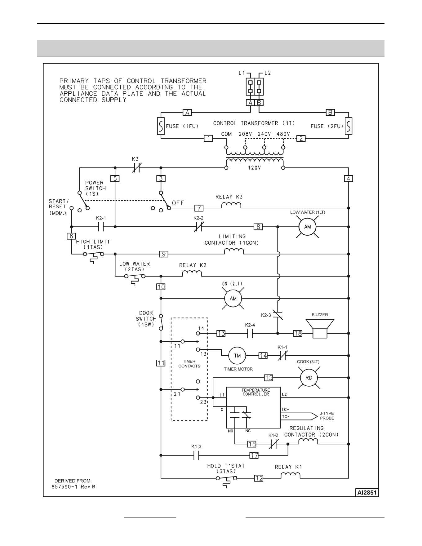
SCHEMATIC DIAGRAM
C24EO SERIES ELECTRIC COUNTERTOP STEAMERS - ELECTRICAL OPERATION
F25386 Rev. C (1023) Page 36 of 44
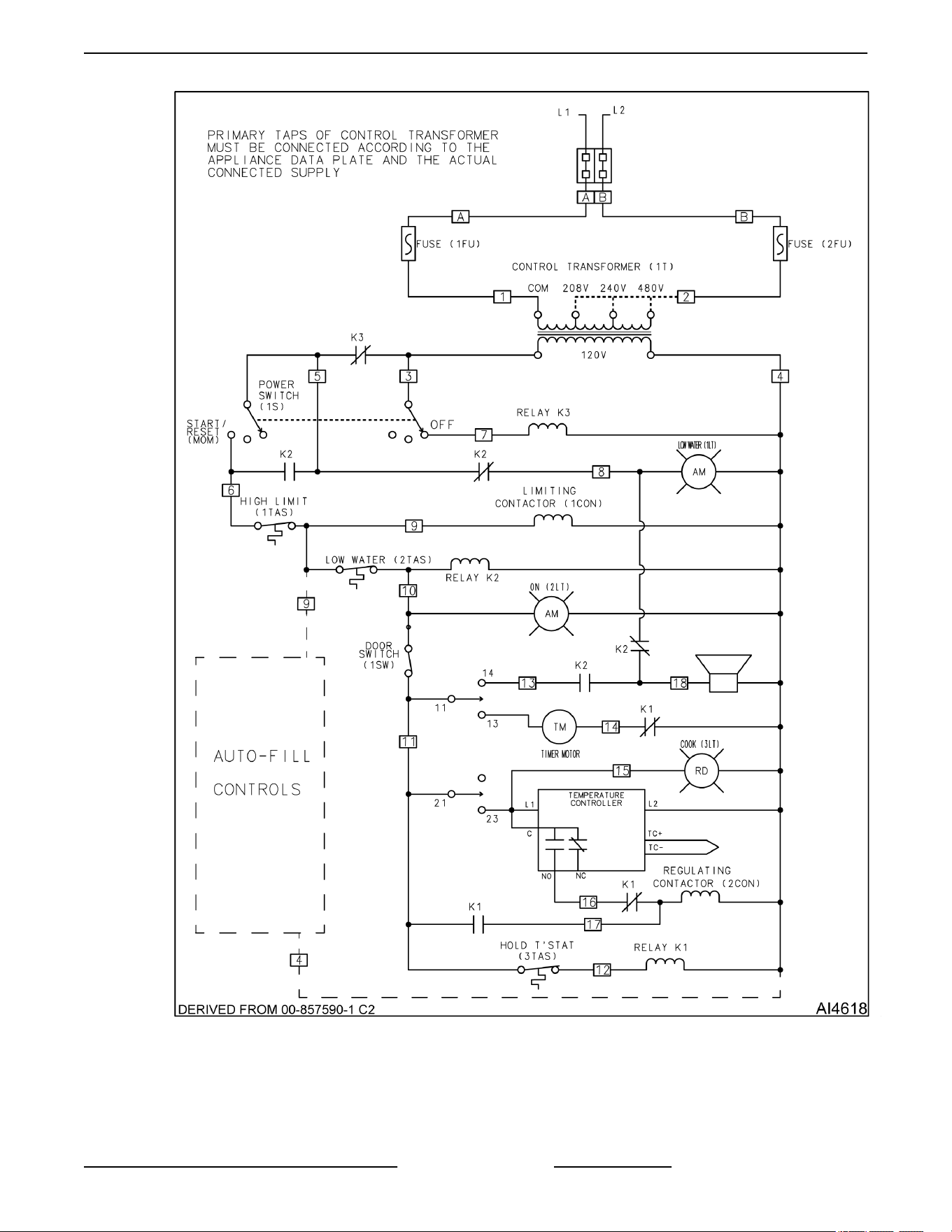
C24EO SERIES ELECTRIC COUNTERTOP STEAMERS - ELECTRICAL OPERATION
Page 37 of 44 F25386 Rev. C (1023)
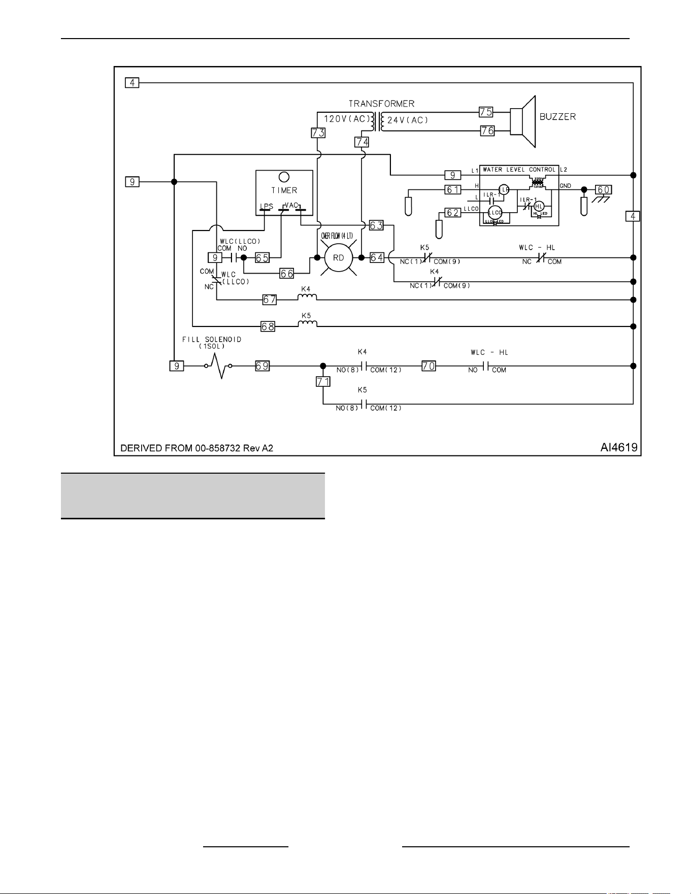
AUTOFILL OPTION
WIRING DIAGRAMS - HEATING
ELEMENTS
C24EO3 - 208V/240V
C24EO SERIES ELECTRIC COUNTERTOP STEAMERS - ELECTRICAL OPERATION
F25386 Rev. C (1023) Page 38 of 44
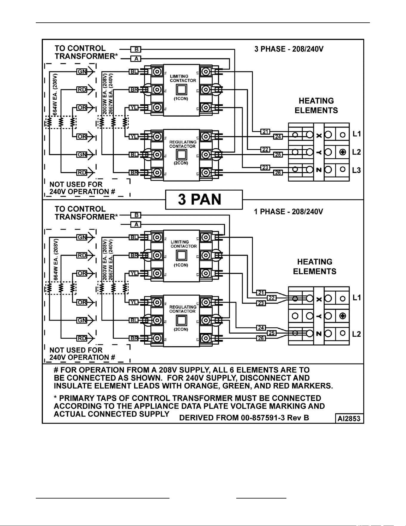
C24EO3 - 208V/240V
C24EO5 - 208V/240V
C24EO SERIES ELECTRIC COUNTERTOP STEAMERS - ELECTRICAL OPERATION
Page 39 of 44 F25386 Rev. C (1023)
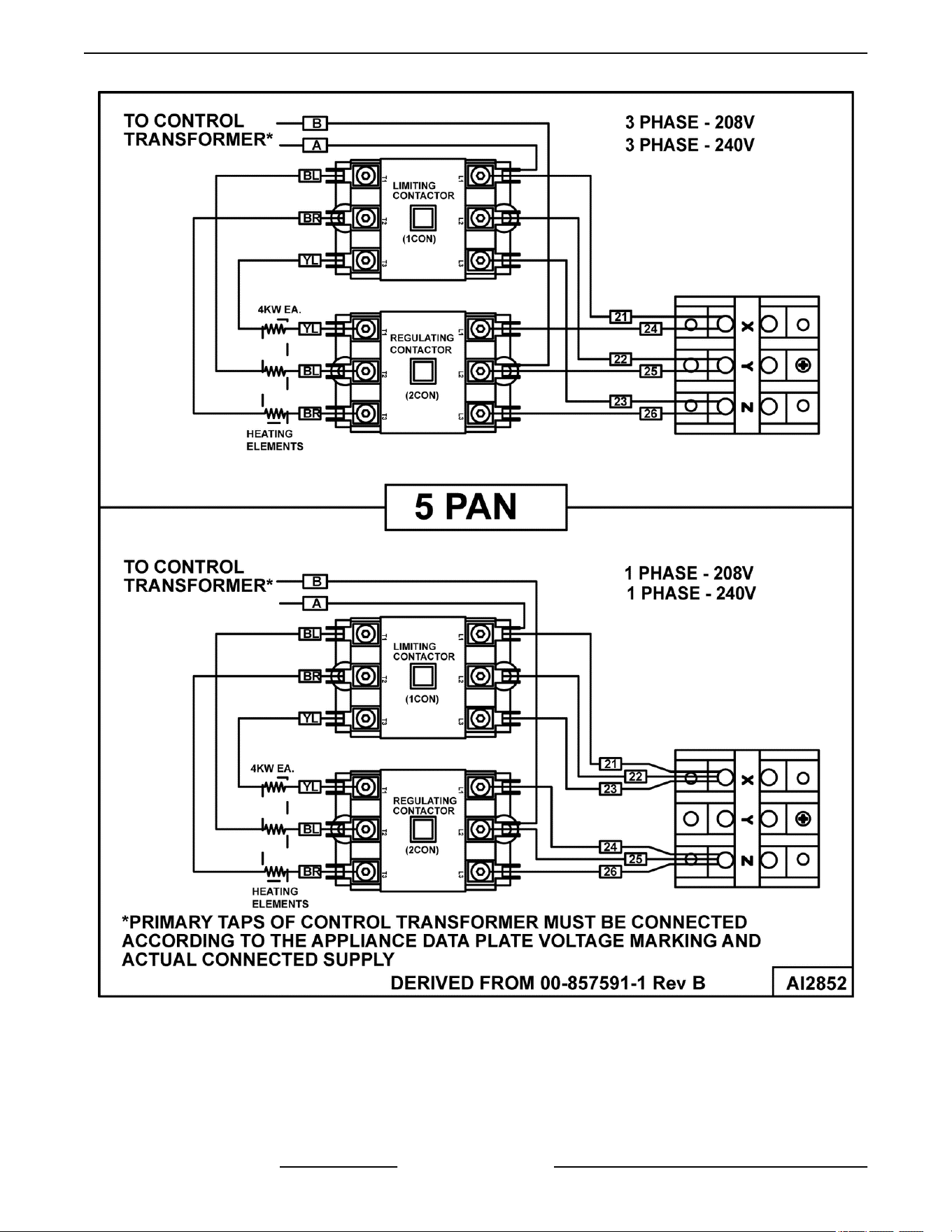
C24EO5 - 208V/240V
C24EO5 - 480V
C24EO SERIES ELECTRIC COUNTERTOP STEAMERS - ELECTRICAL OPERATION
F25386 Rev. C (1023) Page 40 of 44
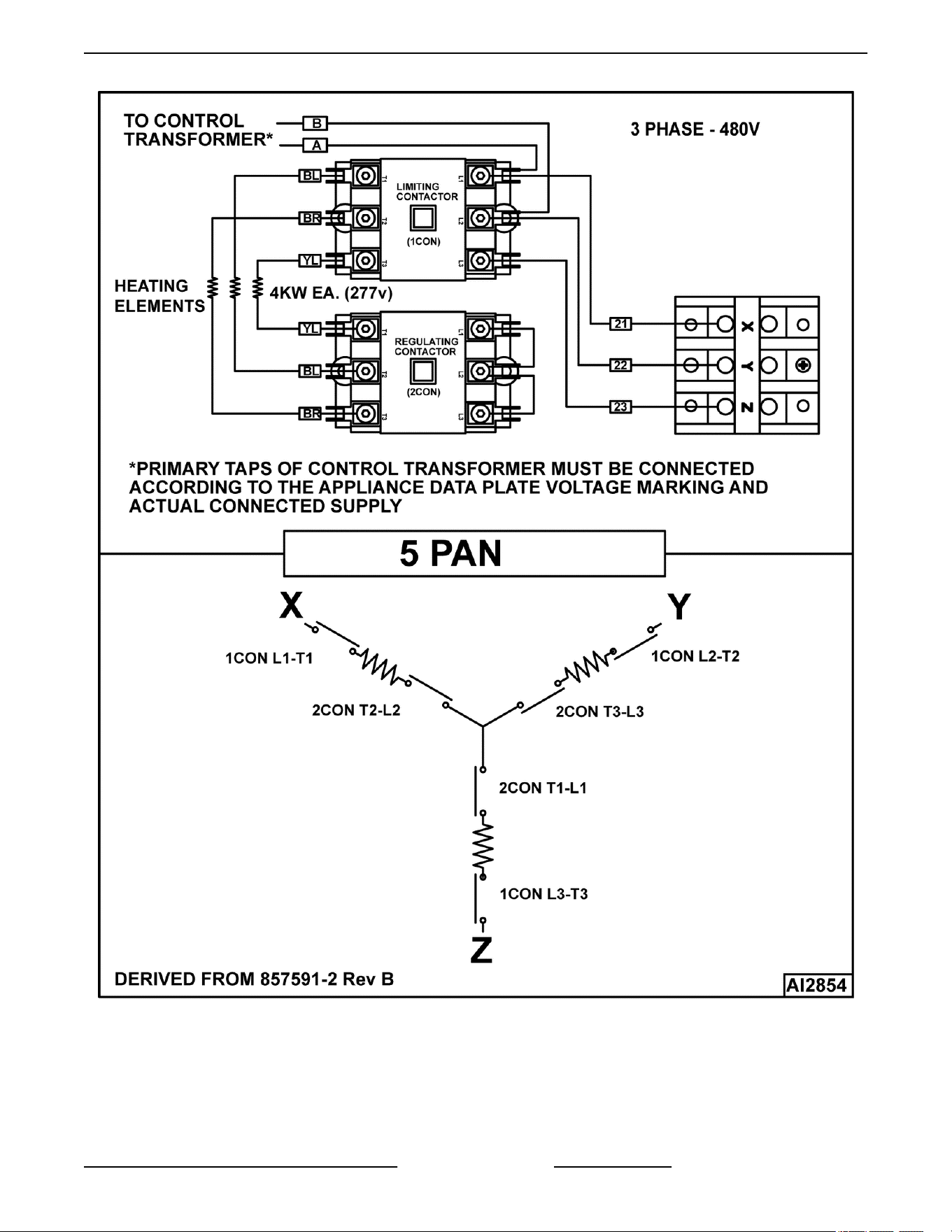
C24EO5 - 480V
C24EO SERIES ELECTRIC COUNTERTOP STEAMERS - ELECTRICAL OPERATION
Page 41 of 44 F25386 Rev. C (1023)
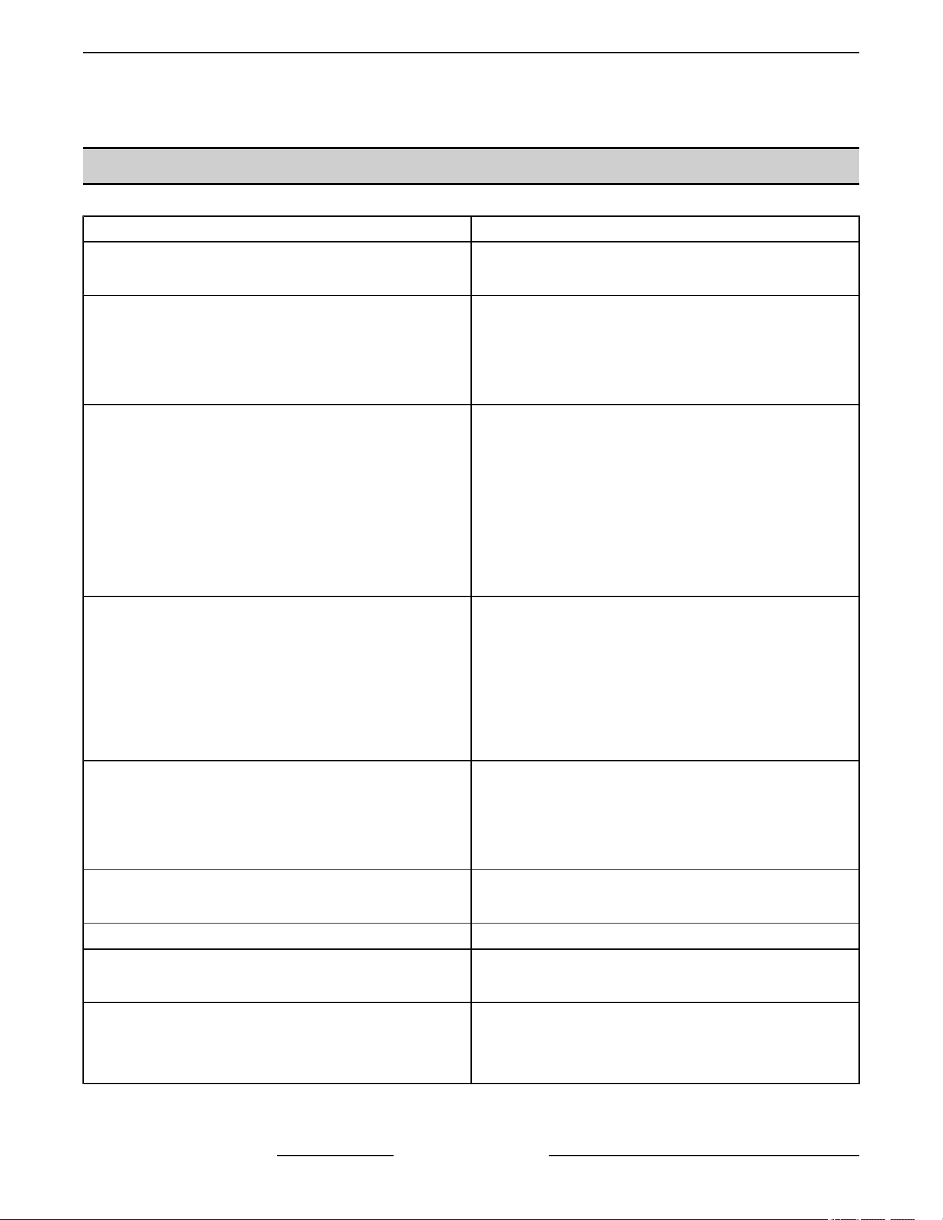
TROUBLESHOOTING
TROUBLESHOOTING
SYMPTOM POSSIBLE CAUSES
Compartment leaks water around door.
1. Steamer not level.
2. Steamer overfilled.
Steam leaks around door.
1. Worn gasket.
2. Damaged gasket.
3. Steam vent pipe blocked.
4. Door not adjusted.
Steamer will not heat (cook light off, low water light off).
1. Line voltage incorrect or transformer malfunction.
2. Control circuit fuse(s) open.
3. High limit thermostat open.
4. Door open or door switch malfunction.
5. Power switch off or inoperative.
6. Relay K3 malfunction.
7. Timer malfunction or timer off (timed mode only).
Steamer will not heat (cook light on, low water light off).
1. Line voltage incorrect.
2. Heating element malfunction.
3. Regulating contactor malfunction.
4. Relay K1 malfunction.
5. Temperature probe malfunction.
6. Temperature controller malfunction.
Timer motor does not run.
1. Door open or door switch malfunction.
2. High limit thermostat open.
3. Low water thermostat open.
4. Timer inoperative.
Door not closing properly.
1. Door latch assembly.
2. Striker adjustment.
Door won’t open. 1. Latch inoperative.
Buzzer not operating.
1. Timer malfunction.
2. Buzzer malfunction.
Water spraying out of steam vent pipe during a cook
cycle.
1. Temperature control set point too high.
2. Temperature probe malfunction.
3. Temperature control malfunction.
C24EO SERIES ELECTRIC COUNTERTOP STEAMERS - TROUBLESHOOTING
F25386 Rev. C (1023) Page 42 of 44
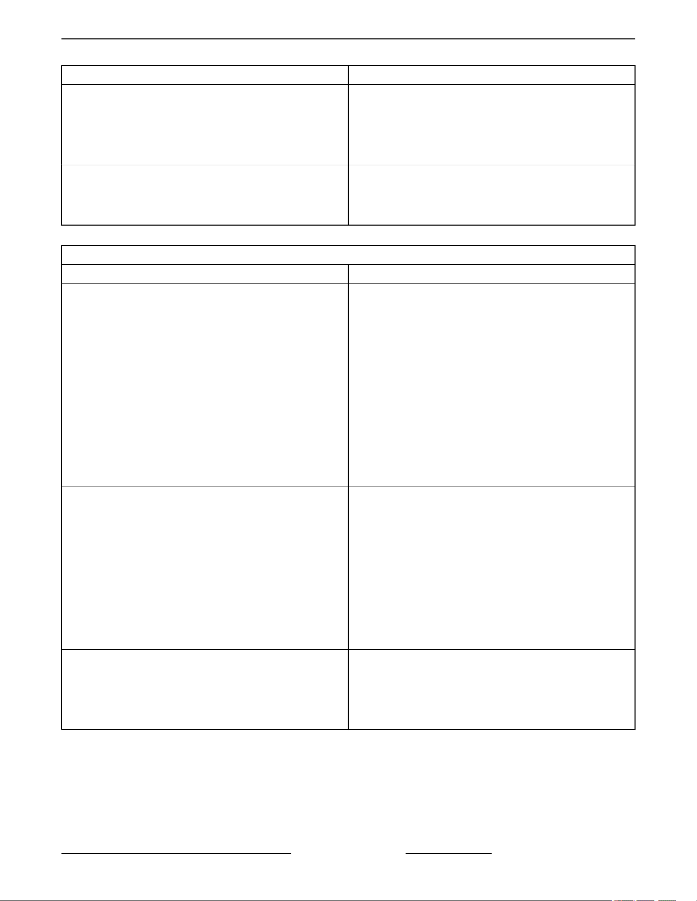
SYMPTOM POSSIBLE CAUSES
High water usage.
1. Temperature control set point too high.
2. Temperature probe malfunction.
3. Temperature control malfunction.
4. Steamer operating in constant mode.
Excessive or inconsistent cook times.
1. Door left open between loads.
2. Temperature control set point too low.
3. Heating element malfunction.
AUTOFILL OPTION
SYMPTOM POSSIBLE CAUSES
Steamer will not fill.
1. Verify water supply.
• Water pressure, 20-60 psi.
2. Verify supply valve is on.
3. Verify screen on valve is free of obstructions.
4. Verify power supply to water level control board.
5. Verify operation of the water level control board.
6. Verify Probes are free of scale.
7. Verify Probes are connected properly.
8. Verify hoses are not kinked.
9. Verify water supply lines are not kinked.
Steamer overfills.
1. Verify time delay relay is set at 10 seconds.
2. Verify probes are wired correctly.
3. Verify probes are free of scale.
4. Verify power supply to water level control board.
5. Verify operation of the water level control board.
6. Verify water supply.
• Water pressure, 20-60 psi.
7. Unit is grounded properly.
Buzzer does not work.
1. Check 24VAC to buzzer.
2. Check transformer wiring.
3. Check time delay relay.
4. Verify operation of water level control board.
C24EO SERIES ELECTRIC COUNTERTOP STEAMERS - TROUBLESHOOTING
Page 43 of 44 F25386 Rev. C (1023)
AUTOFILL OPTION
SYMPTOM POSSIBLE CAUSES
Overfill light not illuminating.
1. Check 120VAC to light.
2. Verify power supply to water level control board.
3. Verify operation of the water level control board.
4. Verify water supply.
• Water pressure, 20-60 psi.
5. Verify supply valve is on.
6. Verify screen on valve is free of obstructions.
7. Verify time delay relay is at 10 seconds.
8. Verify time delay relay is working properly.
Time delay relay not working.
1. Verify 120VAC to TDR.
2. Verify K4 wiring is correct.
3. Verify power supply to water level control board.
4. Verify operation of the water level control board.
Water leaks inside the control area.
1. Verify water supply.
• Water pressure, 20-60 psi.
2. Verify all hose connections.
• Check hoses for damage.
• Replace any leaking hose clamps.
3. Check probes.
• Verify probes are securely installed.
• Check seals for cracks or damage.
4. Verify drain is not leaking.
5. Verify water valve is not cracked.
6. Verify cold water is supplied to unit.
Unit will not run properly if supply water is hot. Must
be a cold water supply.
7. Check cavity welds for cracks.
8. Verify unit was not power washed.
C24EO SERIES ELECTRIC COUNTERTOP STEAMERS - TROUBLESHOOTING
F25386 Rev. C (1023) Page 44 of 44