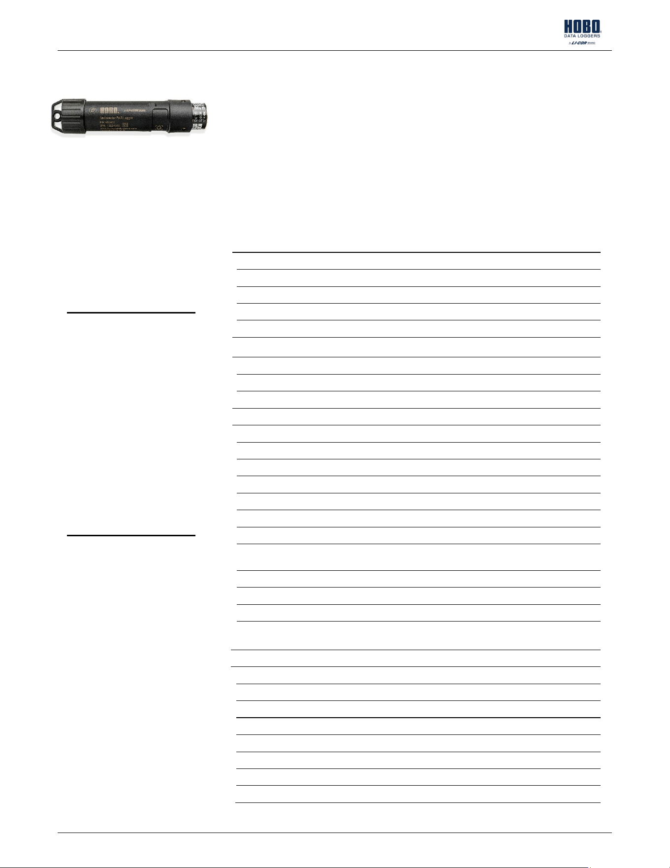
HOBO® MX Underwater PAR Data Logger (MX2502) Manual
29772-A
The HOBO MX2502 PAR/Temp/Tilt Data Logger measures underwater photosynthetically active
radiation (PAR), temperature, and tilt in a single device. This Bluetooth®-enabled logger is
designed for wireless communication with a phone, tablet, or computer. Using the
HOBOconnect® app, you can easily configure the logger then download logged data to view or
export for further analysis. The logger can calculate minimum, maximum, average, and
standard deviation statistics and be configured to indicate alarms at thresholds you specify. The
logger also supports burst logging, in which data is logged at a faster interval when sensor
readings are above or below certain limits. It offers a wide range of solutions for monitoring
PAR, temperature, and tilt in numerous applications.
Specifications
Temperature Sensor
Range
-20° to 50°C (-4° to 122°F)
Accuracy
±0.2°C
Resolution
0.008
°C (0.014°F)
Drift
<0.01°C (0.018°F) per year
Response Time
(90%)
12 minutes
in water (typical)
Tilt
Angle
Range
0 to 180° from vertical
Accuracy
±5°
Resolution
1°
Photosynthetically Active Radiation (PAR)
Range
0 to 3,000 μmol/m²/s (full sunlight)
Accuracy
±5% typical (
LI-COR LI-192 factory calibration)
Offset
+/
-1 μmol
Resolution
0.1
6 μmol/m²/s
Spectral Range
400
–700 nm (PAR waveband)
Linearity
Maximum deviation of 1% up to 3,000umol/m
2
/s
Stability
<= 2% change over one year
Temperature
Dependence
±0.15% per ˚C maximum
Cosine Correction
Optimized for underwater and atmospheric use
Azimuth
<±1% error over 360˚ at 45˚ elevation
Detector
High stability silicon photovoltaic detector (blue enhanced)
Sensor Housing
Corrosion resistant metal with acrylic diffuser for saltwater and
freshwater applications
Logger
Operating Range
-
20° to 50°C (-4° to 122°F); fresh or saltwater; cannot be frozen in ice
Radio Power
1.0
mW (0 dBm)
Transmission Range
Approximately 30.5 m (100 ft) line
-of-sight
Wireless Data Standard
Bluetooth Low Energy (Bluetooth Smart)
Logging Rate
1 second to 18 hours
Logging Modes
Fixed interval (normal, statistics) or burst
Memory Modes
Wrap when full or stop when full
Start Modes
Immediate, push button, date & time, or next interval
HOBO MX2502 Data Logger
Models:
• MX2502, PAR/temp/tilt
Included Items:
• Magnetic activation fob
• Light sensor cap
Required Items:
• HOBOconnect app
• Mobile device with Bluetooth
and iOS, or Android™, or a
Windows computer with
Bluetooth
Accessories:
• Lowering Frame (M-FRM)
• Bracket Mount (M-BRK-2)
• Wiper Clamp (M-CLP)
HOBO MX2502 Underwater PAR Data Logger Manual
1-508-759-9500 (U.S. and International) 2 www.onsetcomp.com
1-800-LOGGERS (U.S. only)
Stop Modes
When memory is full, push button, date & time, or after a set logging
period
Time Accuracy
±1 minute per month 0° to 50°C (32° to 122°F)
Battery Type
2/3 AA 3.6 Volt lithium
, factory replaceable
Battery Life
3
years, typical with logging interval of 1 minute and Bluetooth Always On
enabled;
6 years, typical with logging interval of 1 minute and Bluetooth
Always On
& LED disabled. Faster logging intervals and statistics sampling
intervals, burst logging, remaining connected with the app, excessive
downloads, and paging may impact battery life.
Memory
195,000 measurements
, maximum
Full Memory Download
Time
Approximately 4
-5 minutes; may take longer the further the device is
from the logger
Dimensions
Diameter: 1.695"
Length: 7.190"
Weight
Logger: 274 g (0.604 lb.)
With packaging: 495 g (1.091 lb.)
Materials
Housing:
ENTEC PINNACLE PP 4220H 4% COLOR LOADING 2U2069 BLACK
Cap:
BLACK DELRIN 500P
Environmental Rating
IP6
8 up to 30 m
The CE Marking identifies this product as complying with all relevant
directives in the European Union (EU).
The UKCA marking identifies this product as complying with all relevant
directives in the UK Declaration of Conformity.
Logger Components and Operation
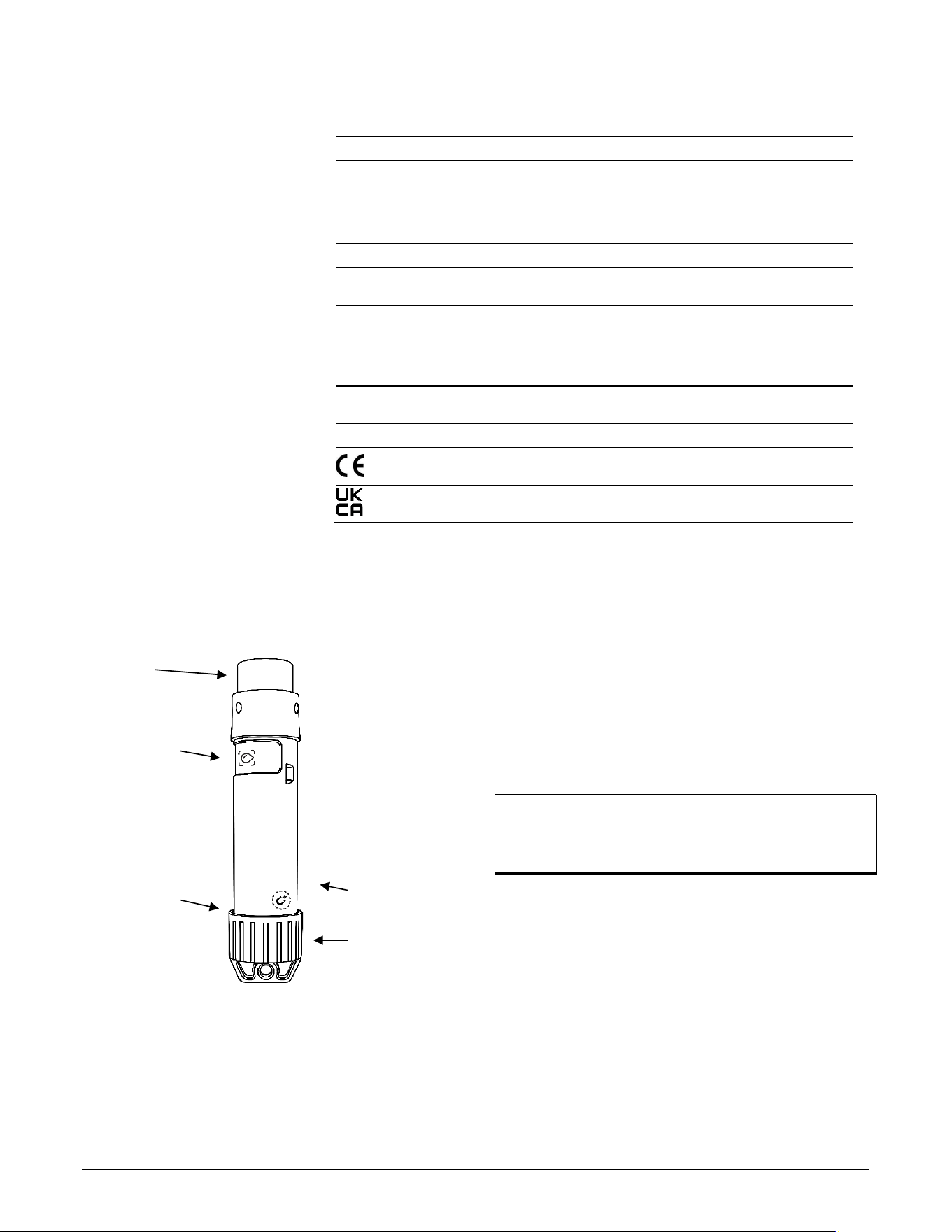
End Cap: This end cap is removable to allow visual access to the
status LED. To remove, twist the end cap clockwise. To replace,
twist the cap counterclockwise; do not overtighten.
Status LED: This LED blinks red every 4 seconds when the logger
is logging (unless Show LED is disabled as described in
Configuring the Logger). If the logger is waiting to start logging
because it was configured to start On Button Push or with a
delayed start, it blinks every 8 seconds.
Alarm LED: This LED blinks red every 4 seconds when an alarm
is tripped (unless Show LED is disabled as described in
Configuring the Logger).
WAKE Icon: This icon indicates the activation point for the
logger. To wake the logger, hold the magnetic activation fob on
the WAKE magnet icon (see Waking the Logger and Bluetooth
Communication).
Important: When storing or transporting the logger, keep the
magnetic fob (or any other magnet) a minimum of 1” away
from the logger so that you do not inadvertently drain the
logger’s battery.
Water Detect Icon: This icon indicates the required water level
for detection. The logger must be submerged until the water
reaches at least this icon for proper operation.
Light Sensor: This light sensor takes PAR measurements and is
protected by a red light sensor cap. Replace the cap when the
logger is not in use.
The logger can record two types of data: samples and events.
Samples are the sensor measurements recorded at each logging
interval (for example, the light measurement every minute).
Events are independent occurrences triggered by a logger
activity, such as Bad Battery or Host Connected. Events help
you determine what was happening while the logger was
logging.
Water detect icon
Warning: Do not
place mounting
equipment on the
water detect icon.
Removable end cap
WAKE icon
Light sensor
LED
HOBO MX2502 Underwater PAR Data Logger Manual
1-508-759-9500 (U.S. and International) 3 www.onsetcomp.com
1-800-LOGGERS (U.S. only)
Waking the Logger and Bluetooth
Communication
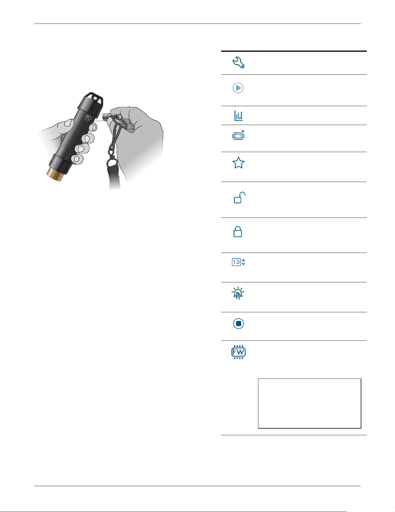
To communicate with the logger, you may need to wake up the
logger using the magnetic fob. To do so, hold the magnetic fob
on the WAKE magnet icon. This wakes the logger if it is asleep
and turns on Bluetooth communication if it is off.
Downloading the App and Connecting to a
Logger
Install the app to connect to and work with the logger.
1. Download HOBOconnect to a phone or tablet from the App
Store® or Google Play™.
Download the app to a Windows computer from
www.onsetcomp.com/products/software/hoboconnect.
2. Open the app and enable Bluetooth in the device settings if
prompted.
3. Wake the logger (see Waking the Logger and Bluetooth
Communication).
4. Under Devices, tap the logger tile to connect to the logger.
If the logger does not appear or if it is having trouble
connecting, follow these tips:
• Make sure the logger is awake by holding the magnetic
activation fob to the WAKE icon.
• Make sure the logger is within range of the mobile device
or computer. The range for successful wireless
communication out of water is approximately 30.5 m
(100 ft) with full line-of-sight.
• If there are several loggers in the area, move the logger
to a location with fewer loggers. Interference sometimes
occurs when numerous loggers are in one location.
• If your device can connect to the logger intermittently or
loses its connection, then move closer to the logger—
within sight if possible.
• If the logger appears in the app but cannot be connected,
close the app then power down the device to force the
previous Bluetooth connection to close.
Once the logger is connected, you can:
Tap this: To do this:
Specify logger settings and save them onto the
logger to start logging. See Configuring the
Logger.
Start logging if the logger was configured to start
with a button push. See Configuring the Logger.
Tap to view live data.
Download logger data. See Downloading Data
from the Logger.
Mark the logger as a favorite. You can then filter
the list of devices to show only loggers marked as
favorites.
Lock the logger. Set a password for the logger so
that it is not mistakenly stopped or reconfigured.
See Setting a Password for more information.
Manage Password. Reset your existing password
or set a new password for the logger. See Setting
a Password for more information.
Reset or set the user calibration factor. The
calibration factor must be in the range of 0.5 to
1.5. See Calibrating the Sensor for more
information.
Illuminate the logger LEDs for 4 seconds.
Stop logging data (this overrides any Stop
Logging settings described in Configuring the
Logger).
Update the firmware on the logger. A logger
readout will be completed automatically at the
beginning of the firmware update process.
Note: FW button is only visible when a firmware
update is available online.
Important: Before updating the firmware on
the logger, check the remaining battery level
and make sure it is no less than 30%. Make
sure you have the time to complete the
entire update process, which requires that
the logger remains connected to the device
during the upgrade.
Configuring the Logger
Use the app to set up the logger, including setting alarms,
selecting the options to start and stop logging, and choosing a
logging mode. These steps provide an overview of setting up
HOBO MX2502 Underwater PAR Data Logger Manual
1-508-759-9500 (U.S. and International) 4 www.onsetcomp.com
1-800-LOGGERS (U.S. only)
the logger. For complete details, see the HOBOconnect User
Guide.
1. In the app under Devices, tap the logger tile to connect to
the logger.
2. Tap Customize Configuration & Start to configure the
logger. If the logger contains data that has not been
downloaded, tap Yes to reconfigure it anyway or No to
return to the previous screen.
3. Tap Logger Name & Group and type a name for the logger.
If you do not enter a name, the app uses the logger’s serial
number as the name. Tap Group to add the logger to a new
or existing group. Type the group name in the field to
create a new group.
4. Tap Logger Settings to configure the logger’s logging
settings.
• Logging Interval: Customize the logging frequency
unless it is operating in burst logging mode (see Burst
Logging). Note: Minimum custom logging time is 1
second. Note: If an alarm is configured, the logger
uses the logging interval as the rate to check for
alarm conditions (alarms are not available if Burst
Logging is selected). See Setting Up Alarms for more
details.
• Logging Capacity: View an estimate of the amount of
data the logger’s memory can retain at the selected
settings.
• Start Logging: Choose when logging begins.
On Save. Logging begins immediately after
configuration settings are saved.
On Next Interval. Logging begins at the next even
interval as determined by the selected logging
interval.
On Button Push. Logging begins when you start
logging with the app.
On Date/Time. Logging begins at a date and time you
specify. Select the Date and Time.
• Stop Logging: Choose when logging ends.
Never Stop (Overwrites Old Data). The logger does
not stop at any predetermined time. The logger
continues recording data indefinitely with newest
data overwriting the oldest.
On Date/Time. The logger stops logging on a specific
date and time that you specify.
After. The logger stops logging after a specific
amount of time that you specify. For example, select
30 days if you want the logger to log data for 30 days
after logging begins.
Stop When Memory Fills. The logger stops recording
data when the memory is full.
Stop on Button Push. The logger stops logging on
button push in the app. This can be selected in
addition to the other options.
• Logging Mode: Choose how the logger records data.
Fixed Logging Mode. The logger records data for all
enabled sensors and/or selected statistics at the
logging interval selected (see Statistics Logging for
details on choosing statistics options).
Burst Mode. Logging occurs at a different interval
when a specified condition is met. See Burst Logging
for more information.
• Calibrations: View the calibration factor and date for
the user calibration factor and calibration constant,
serial number, and date for the LI-COR calibration
constant.
• Power Saving Mode: Choose to enable or disable
Bluetooth.
Bluetooth Always Off: The logger only advertises or
regularly sends out a Bluetooth signal to the phone,
tablet, or computer via the app when logger is woken
up, thereby preserving as much battery power as
possible.
Bluetooth Off Water Detect: The logger stops
advertising or regularly sending out a Bluetooth signal
when water is detected, thereby preserving as much
battery power as possible.
Bluetooth Always On: The logger advertises while it is
logging, which uses battery power.
• Show LED: Choose to enable or disable the status
LED. If disabled, the alarm and status LEDs on the
logger are not illuminated while logging (the alarm
LED does not blink if an alarm trips).
• Update Saved Configuration: Choose to enable or
disable Update Saved Configuration. If enabled, the
configuration settings are applied to the saved
configuration that is used when tapping Start. Saved
configurations can be applied to other loggers in the
same family using the Start with Saved Configuration
option.
5. Tap Underwater PAR to configure the logger’s underwater
PAR settings. Type the sensor or channel name. Choose to
enable or disable logging. If enabled, the logger records
underwater PAR data. See
Measuring Underwater PAR for
more information. Set up an alarm(s) to trip when the
underwater PAR reading rises above or falls below a
specified value. See Setting Up Alarms for more
information.
6. Tap In-Air PAR to configure the logger’s in-air PAR settings.
Type the sensor or channel name. Choose to enable or
disable logging. If enabled, the logger records in-air PAR
data. If In-AIR PAR logging is enabled, Underwater PAR
logging must also be enabled (see previous section). Note:
Disregard underwater PAR data when recording In-AIR PAR
measurements. Note: Disable In-Air PAR logging when
recording underwater PAR measurements.
7. Tap Temperature to configure the logger’s temperature
settings. Type the sensor or channel name. Choose to
enable or disable logging. If enabled, the logger records
temperature data. Set up an alarm(s) to trip when the
temperature reading rises above or falls below a specified
value. See Setting Up Alarms for more information.
8. Tap Tilt to configure the logger’s tilt settings. Type the
sensor or channel name. Choose to enable or disable
logging. If enabled, the logger records tilt data. Set up an
alarm(s) to trip when the tilt reading rises above or falls
below a specified value. See Setting Up Alarms for more
information.
HOBO MX2502 Underwater PAR Data Logger Manual
1-508-759-9500 (U.S. and International) 5 www.onsetcomp.com
1-800-LOGGERS (U.S. only)
9. Tap Daily Light Integral (Underwater) to configure the
logger’s underwater DLI settings. Type the sensor or
channel name. Choose to enable or disable logging. If
enabled, the logger records underwater DLI data. See
Calculating Accumulated Underwater PAR and DLI for more
information.
10. Tap Accumulated Underwater PAR to configure the logger’s
accumulated underwater PAR settings. Type the sensor or
channel name. Choose to enable or disable logging. If
enabled, the logger records accumulated underwater PAR
data. . See
Calculating Accumulated Underwater PAR and
DLI for more information. Set up an alarm(s) to trip when
the accumulated underwater PAR reading rises above a
specified value. See Setting Up Alarms for more
information.
11. Tap Alarm Settings to configure the logger’s alarm settings.
See Setting Up Alarms for more information.
12. Tap LI-COR Cloud Connection to configure the logger’s LI-
COR Cloud® connection settings. If not connected, connect
your LI-COR Cloud account by tapping Settings > LI-COR
Cloud then tapping Connect Account of Create New
Account. An account must be connected to upload data.
See the HOBOconnect User Guide and LI-COR Cloud help for
more information.
13. Tap Start at the top of the lefthand menu to save the
configuration settings and start logging based on the
settings you selected. Tap Start Logger if it is set to start
logging with a button push. See Mounting and Deploying
the Logger for details on mounting and Downloading Data
from the Logger for downloading.
Setting Up Alarms
You can set an alarm to trip on the logger when a sensor
reading rises above or falls below a specified value. Alarms alert
you to problems so you can take corrective action. To set an
alarm:
1. In the app under Devices, tap the logger tile to connect to
the logger.
2. Tap Customize Configuration & Start then tap a
Sensor/Channel in the lefthand menu. Tap Enable Logging if
necessary then tap Alarms.
• Low: Select if you want an alarm to trip when the
sensor reading falls below the low alarm value. Enter
a value to set the low alarm value.
• High: Select if you want an alarm to trip when the
sensor reading rises above the high alarm value. Enter
a value to set the high alarm value.
• Duration: Choose how much time should elapse
before the alarm trips by selecting one of the
following:
Cumulative Samples. The alarm trips once the sensor
reading is out of the acceptable range for the selected
duration any time during logging. For example, if the
high alarm is set to 85°F and the duration is set to 30
minutes, the alarm trips once the sensor readings
have been above 85°F for a total of 30 minutes since
the logger was configured.
Consecutive Samples. The alarm trips once the
sensor reading is out of the acceptable range
continuously for the selected duration. For example,
the high alarm is set to 85°F and the duration is set to
30 minutes, the alarm trips only if all sensor readings
are 85°F or above for a continuous 30-minute period.
3. Tap Alarm Settings in the lefthand menu. In Show Visual
Alarms Until, choose how the alarm indications are cleared:
• Logger Reconfigured. The alarm icon indication
appears until the next time the logger is reconfigured.
• Sensor in Limits. The alarm icon indication displays
until the sensor reading returns to the normal range
between any configured high and low alarm limits.
When an alarm trips, the logger alarm LED blinks every 4
seconds (unless Show LED is disabled), an alarm icon appears in
the app, and an Alarm Tripped event is logged. The alarm state
clears when the readings return to normal if you have specified
Sensor in Limits. Otherwise, the alarm state remains in place
until the logger is reconfigured.
Notes:
• The logger checks alarm limits at every logging interval. For
example, if the logging interval is set to 5 minutes, the
logger checks the sensor readings against the configured
high and low alarm setting every 5 minutes.
• The actual values for the high and low alarm limits are set
to the closest value supported by the logger. In addition,
alarms can trip or clear when the sensor reading is within
the resolution specifications.
• When downloading data from the logger, alarm events can
be displayed on the plot or in the data file. See Logger
Events for more information.
Burst Logging
Burst logging is a logging mode that allows you to set up more
frequent logging when a specified condition is met. For
example, the logger is recording data at a 5-minute logging
interval and burst logging is configured to log every 30 seconds
when the temperature rises above 85°F (the high limit) or falls
below 32°F (the low limit). This means the logger records data
every 5 minutes as long as the temperature remains between
85°F and 32°F. Once the temperature rises above 85°F, the
logger switches to the faster logging rate and records data
every 30 seconds until the temperature returns to 85°F. Logging
then resumes every 5 minutes at the fixed logging interval.
Similarly, if the temperature falls below 32°F, the logger
switches to burst logging mode again and records data every 30
seconds. Once the temperature rises back to 32°F, the logger
returns to fixed mode, logging every 5 minutes. Note: Sensor
alarms, statistics, and the Stop Logging option Never Stop
(Overwrites Old Data) are not available in burst logging mode.
To set up burst logging:
1. In the app under Devices, tap the logger tile to connect to
the logger.
2. Tap Customize Configuration & Start then tap Logger
Settings in the lefthand menu. Tap Logging Mode then
select Burst Logging Mode.
• Burst Logging Interval: Set the burst logging interval,
which must be faster than the logging interval. Note:
The faster the burst logging rate, the greater the
impact on battery life and the shorter the logging
HOBO MX2502 Underwater PAR Data Logger Manual
1-508-759-9500 (U.S. and International) 6 www.onsetcomp.com
1-800-LOGGERS (U.S. only)
duration. Because measurements are being taken at
the burst logging interval throughout the
deployment, the battery usage is similar to what it
would be if you had selected this rate for the fixed
logging interval.
• Temperature, RH, Photosynthetically Active
Radiation, and Accumulated PAR:
Low. Select if you want an alarm to trip when the
sensor reading falls below the low alarm value. Enter
a value to set the low alarm value.
High. Select if you want an alarm to trip when the
sensor reading rises above the high alarm value. Enter
a value to set the high alarm value.
Notes:
• The high and low burst limits are checked at the burst
logging interval rate whether the logger is in fixed or burst
condition. For example, if the logging interval is set to 1
hour and the burst logging interval is set to 10 minutes, the
logger always checks for burst limits every 10 minutes.
• If high and/or low limits are configured for more than one
sensor, burst logging begins when any high or low condition
goes out of range. Burst logging does not end until all
conditions on all sensors are back within normal range.
• The actual values for the burst logging limits are set to the
closest value supported by the logger.
• Burst logging can begin or end when the sensor reading is
within the resolution specifications. This means the value
that triggers burst logging may differ slightly from the value
entered.
• Once the high or low condition clears, the logging interval
time is calculated using the last recorded data point in burst
logging mode, not the last data point recorded at the fixed
logging rate. For example, the logger has a 10-minute
logging interval and logged a data point at 9:05. Then, the
high limit is surpassed and burst logging begins at 9:06.
Burst logging then continues until 9:12 when the sensor
reading falls back below the high limit. Now back in fixed
mode, the next logging interval is 10 minutes from the last
burst logging point, or 9:22 in this case. If burst logging had
not occurred, the next data point would have been at 9:15.
• A New Interval event is created each time the logger enters
or exits burst logging mode. See Logger Events for details on
plotting and viewing the event. In addition, if the logger is
stopped with a button push while in burst logging mode, a
New Interval event is automatically logged and the burst
condition is cleared, even if the actual high or low condition
has not cleared.
Statistics Logging
During fixed logging, the logger records data for enabled
sensors and/or selected statistics at the logging interval
selected. Statistics are calculated at a sampling rate you specify
with the results for the sampling period recorded at each
logging interval. The following statistics can be logged for each
sensor:
• The maximum, or highest, sampled value
• The minimum, or lowest, sampled value
• An average of all sampled values
• The standard deviation from the average for all sampled
values
For example, an MX2502 logger is configured with both the
underwater PAR and temperature sensors enabled, and the
logging interval is set to 5 minutes. The logging mode is set to
fixed logging and all four statistics enabled and with a statistics
sampling interval of 30 seconds. Once logging begins, the logger
measures and records the actual underwater PAR and
temperature values every 5 minutes. In addition, the logger
takes an underwater PAR and temperature sample every 30
seconds and temporarily stores them in memory. The logger
then calculates the maximum, minimum, average, and standard
deviation using the samples gathered over the previous 5-
minute period and logs the resulting values. When reading out
the logger, this results in 10 data series: two sensor series (with
underwater PAR and temperature logged every 5 minutes) plus
eight maximum, minimum, average, and standard deviation
series (four for underwater PAR and four for temperature with
values calculated and logged every 5 minutes based on the 30-
second sampling).
To log statistics:
1. In the app under Devices, tap the logger tile to connect to
the logger.
2. Tap Customize Configuration & Start. Under Logger
Settings, tap Logging Mode then select Fixed Logging Mode.
Toggle Statistics to ON.
Note: Fixed Logging Mode records sensor measurements
taken at each logging interval. The selections made in the
Statistics section add measurements to the recorded data.
3. Select the statistics you want the logger to record at each
logging interval: Maximum, Minimum, Average, and
Standard Deviation. Average is automatically enabled when
selecting Standard Deviation. Statistics are logged for all
enabled sensors. In addition, the more statistics you record,
the shorter the logger duration and the more memory is
required.
4. Tap Statistics Sampling Interval and select the rate to use
for calculating statistics. The rate must be less than, and a
factor of, the logging interval. For example, if the logging
interval is 1 minute and 5 seconds was selected for the
sampling rate, the logger takes 12 sample readings between
each logging interval (one sample every 5 seconds for a
minute) and use the 12 samples to record the resulting
statistics at each 1-minute logging interval. Note: The faster
the sampling rate, the greater the effect on battery life.
Because measurements are being taken at the statistics
sampling interval throughout the deployment, the battery
usage is similar to what it would be if you had selected this
rate for the fixed logging interval.
Calibrating the Sensor
It is recommended to calibrate the logger’s PAR sensor every
two years since sensor drift can cause readings to deviate from
the true PAR value. If the user wishes to correct for this drift
HOBO MX2502 Underwater PAR Data Logger Manual
1-508-759-9500 (U.S. and International) 7 www.onsetcomp.com
1-800-LOGGERS (U.S. only)
instead of obtaining a new factory calibration, they can apply
an adjustment using the user calibration constant.
To add a user calibration factor:
1. In the app under Devices, tap the logger tile to connect to
the logger.
2. Tap User Calibration Factor then input the value and tap
Proceed. The number must be in the range of 0.5 to 1.5.
3. Tap Reset Calibration Factor to reset it.
LI-COR calibration constant is a value that is determined by the
factory and is specific to each sensor. The calibration constant
is provided on the sensor’s LI-COR calibration certificate, which
are available on the LI-COR support website. Note: The serial
number provided on the LI-COR calibration certificate is for the
sensor, not the logger.
Setting a Password
You can create an encrypted password for the logger that is
required if another device attempts to connect to it. This is
recommended to ensure that a deployed logger is not
mistakenly stopped or purposely altered by others. This
password uses a proprietary encryption algorithm that changes
with every connection.
To set a password:
1. In the app under Devices, tap the logger tile to connect to
the logger.
2. Tap Lock Logger.
3. Type a password then tap Set. Lock Logger will change to
Manage Password.
To change or reset a password:
1. In the app under Devices, tap the logger tile to connect to
the logger.
2. Tap Manage Password.
3. Type a new password then tap Set or tap Reset to reset it to
factory default. Note: The password can also be reset by
pressing the button on the logger for 10 seconds.
Only the device used to set the password can then connect to
the logger without entering a password; all other devices are
required to enter the password. For example, if you set the
password for the logger with your tablet and then try to
connect to the logger later with your phone, you must enter
the password on the phone but not with your tablet.
Similarly, if others attempt to connect to the logger with
different devices, they are also required to enter the password.
Downloading Data from the Logger
To download data from the logger:
1. In the app under Devices, tap the logger tile to connect to
the logger.
2. Tap Download Data. The logger will download data to the
phone, tablet, or computer.
3. Once the download is complete, tap Done to return to the
previous page or tap Export & Share to save the file in the
specified format.
4. Tap Data on the lefthand menu to view, export, and share
data files.
You can also upload data automatically to LI-COR Cloud. See the
HOBOconnect User Guide and LI-COR Cloud help for more
information.
Logger Events
The logger records the following internal events to track logger
operation and status. You can view events in exported files or
plot events in the app.
To plot events, tap Data then select a file to open.
Tap (if applicable) then tap . Select the channels you
want to plot (e.g., Underwater PAR, In-Air PAR, Temperature,
Tilt, Daily Light Integral (Underwater), Accumulated
Underwater PAR) then tap OK. Additional channels can be
selected depending on the logger’s activity, as seen below:
Channel Name
Definition
Battery Data The battery voltage was logged. Note:
Battery data is only available in
HOBOconnect, not the exported file.
Host Connected The logger was connected to the mobile
device.
Started The logger started logging.
Stopped The logger stopped logging.
Alarm
Tripped/Cleared
An alarm has occurred because the
reading was outside the alarm limits or
back within range. Note: Although the
reading may have returned to a normal
range during logging, an alarm cleared
event will not be logged if the logger was
set up to maintain alarms until
reconfigured.
Water Detect In: The logger is detecting moisture at the
water detect location. The logger could be
partially or completely submerged.
Out: The logger is not detecting moisture
at the water detect location.
Button Up/Down The magnetic activation fob was used to
activate/advertise the logger.
New Interval The logger has switched to logging at the
burst logging rate or back to the normal
rate.
Safe Shutdown The battery level dropped below a safe
operating voltage and the logger
performed a safe shutdown.
End of File Marks the end of data in the file.
Measuring Underwater PAR and In-Air PAR
The logger’s sensor measures underwater PAR and in-air PAR in
μmol·m⁻²·s⁻¹ at its measurement location.
• PAR. The range of light (400 to 700 nm) that the logger’s
sensor measures at the given moment. PAR values are
sampled every 15 seconds throughout the specified logging
interval then averaged together for one PAR value. If the
logging interval is less than 1 minute, then only an
instantaneous reading is taken.
HOBO MX2502 Underwater PAR Data Logger Manual
1-508-759-9500 (U.S. and International) 8 www.onsetcomp.com
1-800-LOGGERS (U.S. only)
Calculating Accumulated Underwater PAR and
DLI
The logger calculates accumulated underwater PAR in mol/m²
and Daily Light Integral (DLI) in mol/m²/day. These parameters
are derived from logged values.
• Accumulated Underwater PAR. The cumulative amount of
underwater PAR the sensor receives. Accumulated
underwater PAR is measured by summing the underwater
PAR measurements and accounting for the duration,
typically from the start of the day up to the latest logged
value (mol/m²).
• Daily Light Integral (Underwater): A measure of the total
amount of light received in a single day in a particular
underwater area. DLI can be used to quantify PAR as moles
of photons per square meter per day (mol/m²/day). See the
LI-COR Measuring Daily Light Integral with the LI-1500 Light
Sensor Logger quick start guide for more information.
Note on accumulated underwater PAR and DLI: Underwater
PAR data continuously accumulates throughout its deployment
and resets automatically at midnight each day.
However, if the logger is stopped, read out, and left
disconnected for more than 1 hour, it will enter storage mode.
This resets both the accumulated underwater PAR and DLI
values. To prevent this, reconnect to or interact with the logger
(e.g., by using the magnetic activation fob) within 1 hour after
stopping it.
Mounting and Deploying the Logger
Follow these guidelines when mounting and deploying the
logger:
To use the logger with a ZebraTech Hydro-Wiper, install the M-
CLP ZebraTech Wiper Clamp. This clamp secures the logger to
the wiper for underwater monitoring applications.
1. Slide the logger into the clamp with the light sensor facing
up. Ensure the O-ring remains properly seated.
2. Adjust the logger position so the wiper brush contacts the
sensor surface, then tighten the thumb screw.
Note: Do not cover the water detect icon on the logger.
Covering this area will prevent the water detect feature
from functioning correctly.
Optional mounting accessories include the M-BRK-2 Bracket
Mount and M-FRM Lowering Frame. The M-BRK-2 Bracket
Mount can be used to secure the logger and wiper assembly to
a rebar stake for underwater monitoring.
The M-FRM Lowering Frame can be used for lowering and
stabilizing the logger and wiper assembly for long-term
deployments, including buoy installations.
Note: Sudden tilt changes often indicate a loose mount and/or
a noisy environment.
For detailed installation instructions for all accessories, see the
HOBO® MX2502 Accessories Install Guide for more information.
Battery Guidelines
The battery in the MX2502 is a 3.6 Volt lithium battery.
• Battery Life. Refer to the Specifications to learn about
battery life. Actual battery life is a function of the number
• of deployments, logging interval, and operation/storage
temperature of the logger. Frequent deployments with
logging intervals of less than one minute, and continuous
storage/operation at temperatures above 35°C result in
significantly lower battery life. For example, continuous
logging at a one-second logging interval results in a battery
life of approximately one month.
To obtain the specified battery life, operate and store the
logger at temperatures between 0° and 25°C (32° and 77°F).
• Battery Level: The battery level shown for these loggers is
based on the battery voltage. The Lithium batteries in these
loggers maintain a flat voltage until they are near the end of
their capacity. Therefore, it is best to replace the batteries
or loggers based on how long they have been deployed.
Once they have been used for 90% of the specified battery
life, you should not use the loggers for extended
deployments. If the loggers are deployed beyond this time,
schedule frequent site visits to minimize the risk of data
loss. Once the battery indication goes below 50% (when
checked at room temperature), you should replace the
loggers or return them to Onset or an authorized Onset
service center for battery replacement and logger tune-
up/recalibration.
WARNING: Do not cut open, incinerate, heat above 100°C
(212°F), or recharge the lithium battery. The battery may
explode if the logger is exposed to extreme heat or conditions
that could damage or destroy the battery case. Do not dispose
of the logger or battery in fire. Do not expose the contents of
the battery to water. Dispose of the battery according to local
regulations for lithium batteries.
HOBO MX2502 Underwater PAR Data Logger Manual
U.S. and International Sales:
1-508-759-9500
www.onsetcomp.com/support/contact
© 2025 Onset Computer Corporation. All rights reserved. Onset, HOBO, and HOBOconnect are registered
trademarks of Onset Computer Corporation. App Store, iPhone, iPad, and iPadOS are service marks or
registered trademarks of Apple Inc. Android and Google Play are trademarks of Google LLC. Windows is a
registered trademark of Microsoft Corporation. Bluetooth and Bluetooth Smart are registered trademarks
of Bluetooth SIG, Inc. All other trademarks are the property of their respective companies.
Patent #: 8,860,569
29433-A
Federal Communication Commission Interference Statement
This equipment has been tested and found to comply with the limits for a Class B digital device, pursuant to Part 15 of the FCC Rules. These limits are designed to provide
reasonable protection against harmful interference in a residential installation. This equipment generates uses and can radiate radio frequency energy and, if not installed and
used in accordance with the instructions, may cause harmful interference to radio communications. However, there is no guarantee that interference will not occur in a
particular installation. If this equipment does cause harmful interference to radio or television reception, which can be determined by turning the equipment off and on, the user
is encouraged to try to correct the interference by one of the following measures:
• Reorient or relocate the receiving antenna
• Increase the separation between the equipment and receiver
• Connect the equipment into an outlet on a circuit different from that to which the receiver is connected
• Consult the dealer or an experienced radio/TV technician for help
This device complies with Part 15 of the FCC Rules. Operation is subject to the following two conditions: (1) This device may not cause harmful interference, and (2) this device
must accept any interference received, including interference that may cause undesired operation.
FCC Caution: Any changes or modifications not expressly approved by the party responsible for compliance could void the user's authority to operate this equipment.
Industry Canada Statements
This device complies with Industry Canada license-exempt RSS standard(s). Operation is subject to the following two conditions: (1) this device may not cause interference, and
(2) this device must accept any interference, including interference that may cause undesired operation of the device.
Avis de conformité pour l’Industrie Canada
Le présent appareil est conforme aux CNR d'Industrie Canada applicables aux appareils radio exempts de licence. L'exploitation est autorisée aux deux conditions suivantes : (1)
l'appareil ne doit pas produire de brouillage, et (2) l'appareil doit accepter tout brouillage radioélectrique subi, même si le brouillage est susceptible d'en compromettre le
fonctionnement.
To comply with FCC and Industry Canada RF radiation exposure limits for general population, the logger must be installed to provide a separation distance of at least 20cm from
all persons and must not be co-located or operating in conjunction with any other antenna or transmitter.