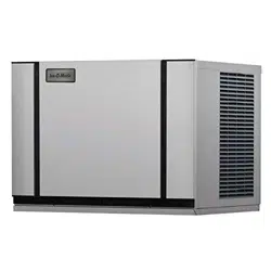
ELEVATION SERIES CUBE ICE MAKER
CIM Modular Cubers
CIM0320 - CIM2046
Ice-O-Matic
11100 East 45th Avenue
Denver, Colorado 80239
1-800-423-3367
Technical Service Manual
9/2025

ELEVATION SERIES CIM CUBERS TABLE OF CONTENTS
Contents
ELEVATION SERIES CIM CUBERS TABLE OF CONTENTS .................................................................................. 2
Installation ............................................................................................................................................... 5
Electrical and Plumbing Requirements................................................................................................... 11
Start-Up Procedure ................................................................................................................................. 14
Sequence of Operations .......................................................................................................................... 15
Control Board ......................................................................................................................................... 29
Board Led Sequence During Operation Test Control Boards .................................................................. 32
Sump ...................................................................................................................................................... 41
High and Low Float Switches and Housing ........................................................................................... 45
Water Pump ............................................................................................................................................ 49
Water Distribution Tube ......................................................................................................................... 50
Water Inlet Valve .................................................................................................................................... 52
Purge Valve ............................................................................................................................................ 53
Harvest Assist Assembly/Hot Gas Valve ................................................................................................ 54
Magnetic Curtain Switch ........................................................................................................................ 55
High Pressure Cut-out and Fan Cycle Switch ......................................................................................... 56
Fan Motor ............................................................................................................................................... 57
Evaporator .............................................................................................................................................. 58
High Temp Safety ................................................................................................................................... 67
Refrigeration Section .............................................................................................................................. 68
Freeze Cycle........................................................................................................................................... 71
Harvest Cycle ......................................................................................................................................... 72
General Maintenance ............................................................................................................................. 73
Cleaning and Sanitizing .......................................................................................................................... 74
Cabinet Care ........................................................................................................................................... 76
Winterizing Procedures .......................................................................................................................... 77

Wiring Diagram ...................................................................................................................................... 71
CIM 115V and 230V, 60Hz, SINGLE PHASE, SINGLE EVAPORATOR AIR AND WATER COOLED UNITS .......................... 71
CIM 220V ‐ 240V, 50Hz, SINGLE PHASE, SINGLE EVAPORATOR PLATE AIR AND WATER COOLED UNITS .................... 72
CIM 115V and 230V, 60Hz, THREE PHASE, SINGLE EVAPORATOR AIR AND WATER COOLED UNITS ........................... 73
CIM 115V and 230V, 60Hz, SINGLE PHASE, SINGLE EVPAORATOR PLATE REMOTE COOLED UNITS ............................ 74
CIM 220V ‐ 240V, 50Hz, SINGLE PHASE, SINGLE EVAPORATOR REMOTE COOLED UINTS ............................................ 75
CIM 230V, 60Hz, THREE PHASE, SINGLE EVAPORATOR PLATE REMOTE COOLED UNITS ............................................. 76
CIM 115V and 230V, 60Hz, SINGLE PHASE, DUAL EVAPORATOR AIR AND WATER COOLED UNITS ............................. 77
CIM 220V ‐ 240V, 50Hz, SINGLE PHASE, DUAL EVAPORATOR AIR AND WATER COOLED UNITS .................................. 78
CIM 230V, 60Hz, THREE PHASE, DUAL EVAPORATOR AIR AND WATER COOLED UNITS .............................................. 79
CIM 115V and 230V, 60Hz, SINGLE PHASE, DUAL EVAPORATOR REMOTE COOLED UNITS ......................................... 80
CIM 220V ‐ 240V, 50Hz, SINGLE PHASE, DUAL EVAPORATOR REMOTE COOLED UNITS .............................................. 81
CIM 230V, 60Hz, THREE PHASE, DUAL EVAPORATOR REMOTE COOLED UNITS ........................................................... 82

1
ELEVATION SERIES CIM CUBERS INTRODUCTION
Introduction
Energy Efficiency
Ice-O-Matic has partnered with ENERGY STAR since 2004 to ensure our customers receive the most
efficient ice machines for your investment dollar. Ice-O-Matic is committed to the continuous
improvement in both energy efficiency and productivity thereby delivering the best value in energy
efficient ice machines money can buy.
Inspect Promptly
For a detailed list of ENERGY STAR qualified Ice-O-Matic ice machines, go to:
http://www.iceomatic.com/Products/Sales-Literature/#
Freight Claims
Concealed Loss or Damage
This merchandise has been carefully inspected
and packed in accordance with the carrier’s
packing specifications. Responsibility for safe
delivery has been assumed by the carrier. If
loss or damage occurs, you as the consignee
must file a claim with the carrier and hold the
container for carrier’s inspection.
Visible Loss or Damage
Any external evidence of loss or damage must
be fully described and noted on your freight
bill or express receipt and signed by the
carrier’s agent. The claim should be filed on a
form available from the carrier.
If loss or damage does not appear until
merchandise has been unpacked, make a
written request for inspection by the carrier
within 5 days of the delivery date, then file a
claim on a form from the carrier.
FILE CLAIMS WITHOUT DELAY
DO NOT RETURN DAMAGED GOODS
TO ICE-O-MATIC
ELEVATION SERIES CIM CUBERS
GENERAL INFORMATION
2
How to use this Manual
Ice-O-Matic provides this manual as an aid to the Refrigeration Service Technician for installation and
maintenance of the CIM cube ice machines. Do not attempt to perform installation, start-up or maintenance
unless you have read and fully understand this manual.
Ice-O-Matic icemakers and dispensers are not approved for outdoor installation.
CIM Cubers contain R404A Refrigerant, R449A Refrigerant, or R290 Refrigerant.
To find a Service Provider, please reference our “Find a Service Technician” tab at www.iceomatic.com
Keep this manual for future reference.
The CIM Series Service Parts Manuals are available separately.
WARNING
Always disconnect electrical power and shut off water supply whenever maintenance or repairs are
performed on the ice machine and related equipment.
CAUTION
Always wear protective eye wear whenever maintenance or repairs are performed on the ice
machine and related equipment.
Ice-O-Matic Warranty
Every Ice-O-Matic ice maker is backed by a warranty that provides both parts and labor coverage. To view
the warranty details, register products, or check your warranty status visit the “Warranty and Water Filter
Registration” page on www.iceomatic.com

ELEVATION SERIES CIM CUBERS
GENERAL INFORMATION
3
Model And Serial Number Format
Model Numbers
CIM 04 3 0 H A 5 49 90
Refrigerant type
Revision Number For Models Prior to Refrigerant Change
Condenser Type, A = Air W=Water R= Remote T=Top Discharge
Cube Sizes: H=Half (3/8 x 7/8 x 7/8), F=Full (7/8 x 7/8 x 7/8), G=Grande (1 1/4 x 1 1/8 x 7/8)
Voltage: 0=115/60/1, 5=220-240/50/1, 6=208-230/60/ 1, 7=208-230/60/3
Cabinet Width: 3= 30”, 2=22”, 4= 48”
Approximate 24 Ice Production: 4 x 10 = 400 pounds per 24 hrs
Series: C=Cuber, I=Ice, M= Modular
Serial Number
The format for the Serial Number is 14 characters long and begins with a date code followed by the Ice‐O‐Matic
identifier, and then a sequential number. This is an entirely numerical serial number.
2508 12800 12345
This is the serial identifier.
Manufacturer (Ice-O-Matic)
This Is the Date Code, YYMM format. Ex. 2025 August
Each serial number provides essential information not only about production dates and manufacturer but also
serves as a key for tracing unit specifications and service history. Accurate identification remains vital, especially
as we move toward new refrigerant standards and labeling requirements
4
ELEVATION SERIES CIM CUBERS
REFRIGERANT CHANGES
REFRIGERANT CHANGES
In compliance with EPA regulations requiring the transition away from R-404A refrigerant, effective January 1, 2026, we
are updating the refrigerants used in our units to more environmentally sustainable options. Larger remote units will
utilize R449A refrigerant, while self-contained units will operate with R-290 refrigerant. Identification of these units will
be facilitated through multiple indicators: the final two digits of the model number (as referenced on the preceding page),
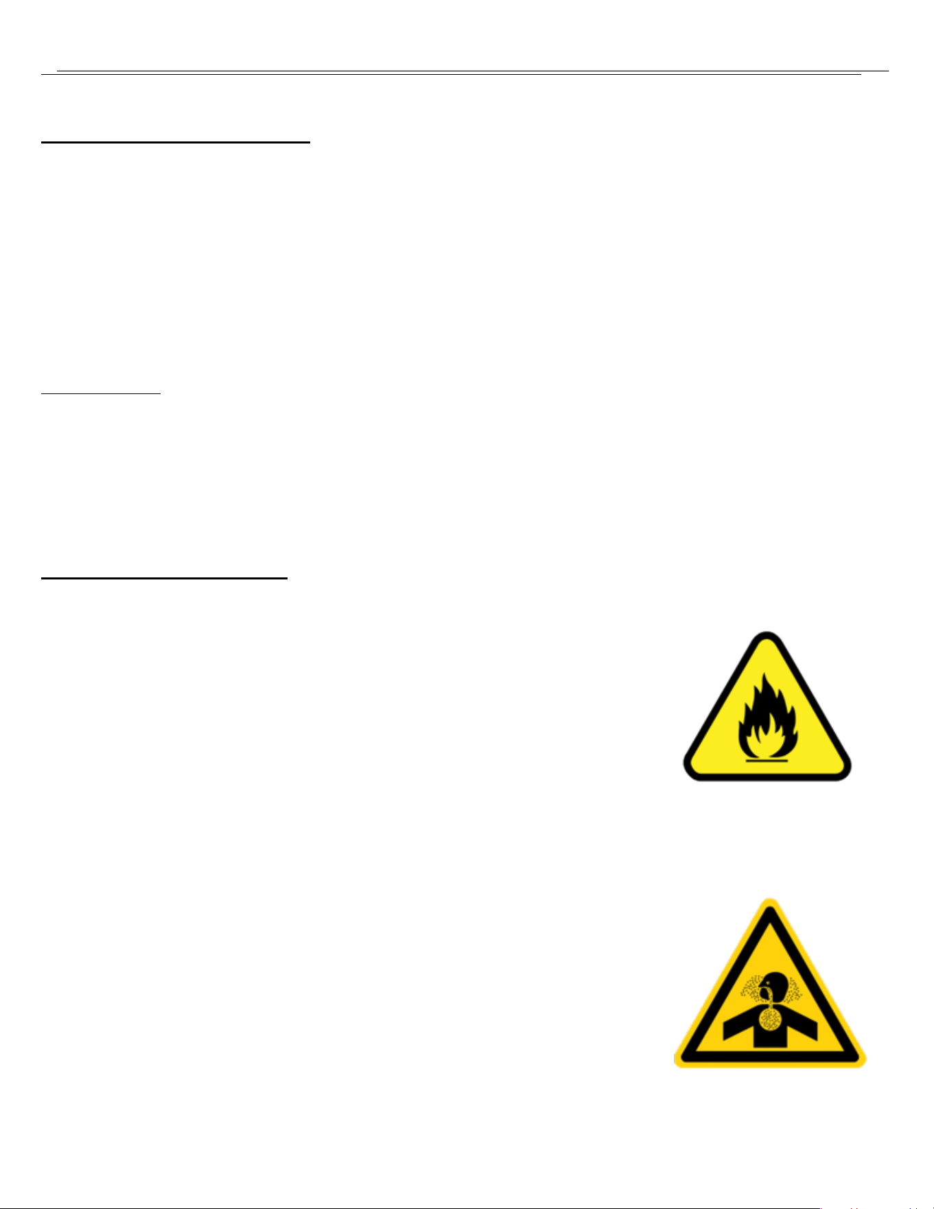
the data tag, and stickers affixed to line-sets. Additionally, R-290 units will feature specific warning labels as detailed
below.
R449 refrigerant possesses characteristics closely resembling those of R-404A, requiring minimal modifications to
existing units aside from a TXV replacement.
In contrast, R-290 exhibits distinct properties that necessitate different considerations.
What is R290?
R290 is Propane
•
Extremely Pure
•
Highly Flammable
•
NO ADDED ODORANT
(no smell)
•
Heavier than air (pools up in low areas)
R290 SAFTEY HAZARDS
Fire/Explosion
Asphyxiation
•
You cannot get enough air to breath – there’s not enough oxygen
•
R404 and R449 are also asphyxiants

5
ELEVATION SERIES CIM CUBERS
INSTALLATION GUIDELINES
Installation Guidelines
For proper operation of the ice machine, the following installation guidelines must be followed by a Qualified
Refrigeration Technician. Failure to do so may result in loss of production capacity, premature part failures,
and may void all warranties.
Reference the installation parameters prior to installing the machine. Ice-O-Matic assumes no responsibility for
improperly installed equipment. Excessive time required for service or time for units requiring removal for
service of inaccessible equipment will be the sole responsibility of the equipment owner.
Ambient Operating Temperature
Minimum operating temperature:
Air cooled units 50°F (10°C)
Remote units -20°F (- 29°C)
Maximum operating temperature:
Air cooled Units 100°F (38°C) (60 Hz.), 110°F (43°C) (50 Hz.).
Remote units 120° F (49°C)
Note: Ice-O-Matic ice-makers and dispensers are not approved for outdoor installation
Incoming Water Supply
WARNING: Connect to unheated potable water supply only!
(See Electrical and Plumbing diagrams for line sizing)
Minimum incoming water temperature: 40°F (4.5°C)
Maximum incoming water temperature: 100°F (38°C)
Minimum incoming water pressure: 20 psi (1.4 bar, 0.138MPa)
Maximum incoming water pressure: 80 psi (5.5 bar, 0.552MPa)
Note: if water pressure exceeds 80 psi (5.5 bar), a water pressure regulator must be installed
All water supply lines must be installed per local codes. Use 3/8 inch O.D. minimum on air cooled machines.
On water cooled machines 3/8 inch O.D. minimum tubing must be run to the condenser. The water supply for the
machine can “T” off from the condenser line using 3/8 inch O.D. minimum tubing. Make 2 coils of extra tubing
so that the machine can be pulled away from the wall if service is needed.
Water Filtration/Treatment
A water filter system should be installed with the ice machine. Refer to Ice-O-Matic water filter
specification sheet.
Reverse Osmosis (RO) water can be very acidic and can attack the evaporator and other metal in the ice
machine. Because the RO process removes all minerals and metals from the water it can promote the faster
growth of microbial mold and slime. If RO water is used, Ice-O-Matic recommends the water pH verified to be
a neutral 7.0 to minimize the corrosive effects. Incorrect cleaners, sanitizers, and RO water that does not have a
neutral pH could void the machine’s warranty.

6
ELEVATION SERIES CIM CUBERS
INSTALLATION GUIDELINES
Drains
All drain lines must be installed per local codes. Flexible tubing is not recommended. Route bin drain, purge
drain and water condenser drain individually to a floor drain. The use of condensate pumps for draining water is
not recommended.
Ice-O-Matic assumes no responsibility for improperly installed equipment. This may void the warranty.
Note: The Purge Drain Fitting is plastic: DO NOT apply heat to the purge drain area;
DO NOT over-tighten drain connection.
The purge drain should be a minimum of 3/4 inch
O.D. tubing, and properly vented. The condenser drain on water cooled units should be 1/2 inch O.D.
minimum. The drain line fittings on Ice-O-Matic bins are 3/4 FPT. The bin drain should be a minimum of
3/4 inch O.D. and properly vented. Cold water drains should be insulated to prevent condensation from
forming.
It is not recommended that a Drain pump be used on CIM Model Ice machines
Clearance Requirements
Self-contained air-cooled ice machines should have a minimum of 6 inches (15cm) of clearance at the rear, top and
sides for proper air circulation and adequate space for serviceability.
Self-contained air-cooled ice machines exhaust air out the top and right side. There are two alternative air exhaust
options. Option A (top exhaust bias): minimum of 6 inches (15cm) of clearance at the rear and top of the ice
machine for proper function at maximum operating conditions. Option B (side exhaust bias): minimum of 6 inches
(15cm) of clearance at the rear and right side of the ice machine with a minimum of 3 inches (7.5cm) of clearance
at the top for proper function at maximum operating conditions.
CAUTION: Improper ventilation will cause unit to Malfunction and Service will not be covered under
Warranty
Appropriate space should be allowed for proper serviceability of the machine.
Excess time to gain access for serviceability is not covered under warranty.
Stacking
Ice-O-Matic does not endorse stacking ice machines.

7
ELEVATION SERIES CIM CUBERS
INSTALLATION GUIDELINES
Dispenser Application
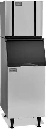
A thermostatic bin control kit is required when installing the CIM Cube ice machine on a dispenser. The use of a bin top
depends on the application and should be secured to the dispenser accordingly.
Electrical Specifications
Check the serial plate at the rear of the ice machine to verify correct voltage and circuit breaker size. The ice machine
should operate on a dedicated circuit. For European installations, the electrical supply fixed wiring must have a
disconnect mechanism with at least 3mm separation in all poles.
These ice machines do not include an electrical cord set and are designed for permanent connection as approved by
relevant agencies
.
Units are not approved for GFI outlets. Electrical connections or cord installation must be performed by a
qualified electrician to prevent electrical hazards.
Adjustments
• Level the machine within 1/8 inch in all directions.
• Inspect the water in the Water Sump to confirm proper level.
• Evaluate the ice bridge thickness and adjust the Float Switch Housing Assembly as necessary.
• If water cooled, check the Water Regulating Valve adjustment.
Note: These adjustments should be completed by a Qualified Service Technician during unit installation;
they are not covered under factory warranty.
Secure the ice machine onto the bin or dispenser using mounting straps provided. Ensure the back of the ice
machine aligns flush with the bin's back. For proper operation, the Bin Door should remain stable when open.
Installing the ice machine too far forward may lead to instability, causing the door to close unexpectedly.
When mounting on bins or dispensers not manufactured by Ice-O-Matic, refer to the manufacturer’s
installation instructions. Ice-O-Matic does not accept responsibility for damage or injury resulting from
improper placement that causes the bin door to close unexpectedly.
ELEVATION SERIES CIM CUBERS
REMOTE CONDENSER GUIDELINES
8
Remote Condenser Installation
For proper operation of the ice machine, the following installation guidelines must be followed. Failure to do
so may result in loss of production capacity, premature part failure, and may void all warranties.
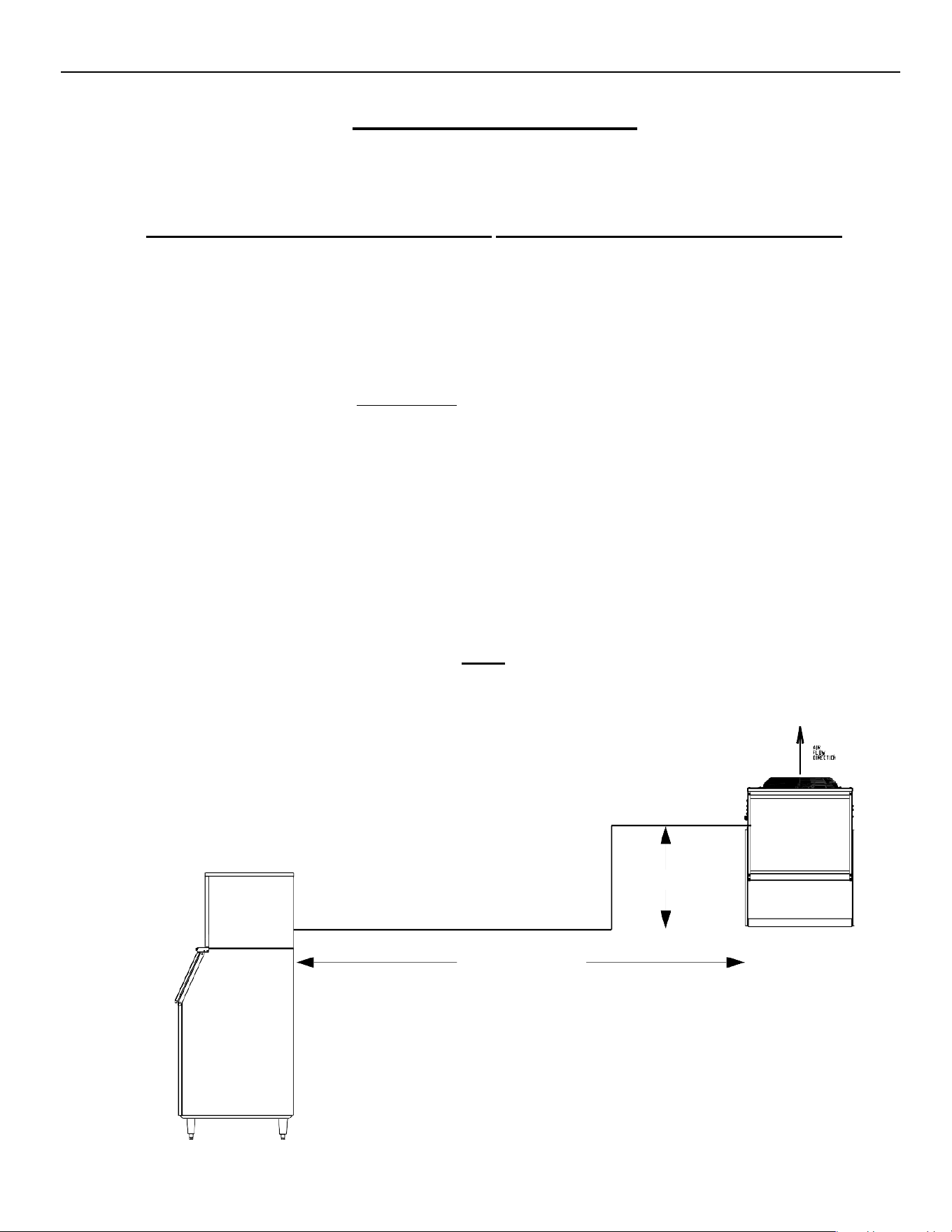
Use the following for planning the placement of the remote condenser relative to the ice machine
Location Limits
Remote condenser location must not exceed ANY
of the following:
The maximum rise from the ice machine to the remote condenser is 35 physical feet.
The maximum drop from the ice machine to the remote condenser is 10 physical feet.
The physical line set maximum length is 75 ft.
The calculated line set maximum length is 100 ft.
Ambient operating temperatures:
-20°F (-28.9°C) to 120°F (48.9°C)
Limitations on line-set runs
Maximum Rise is 35’
Maximum Drop is 10’
Maximum Run Is 100’
Formula for calculating Maximum run is as follows.
Formula for calculating Maximum run is as follows.
RISE
Rise x 1.7 + Horizontal Run = < 100’
Example: 35’ x 1.7 + 40’ = 99.5‘ this is < 100 so it is ok.
NOT TO EXCEED 100 CALCULATED FEET
(35 ft. x 1.7) + (40 ft.) = 99.5 calculated feet line run
35 ft. rise
40 ft. horizontal
ELEVATION SERIES CIM CUBERS
REMOTE CONDENSER GUIDELINES
9
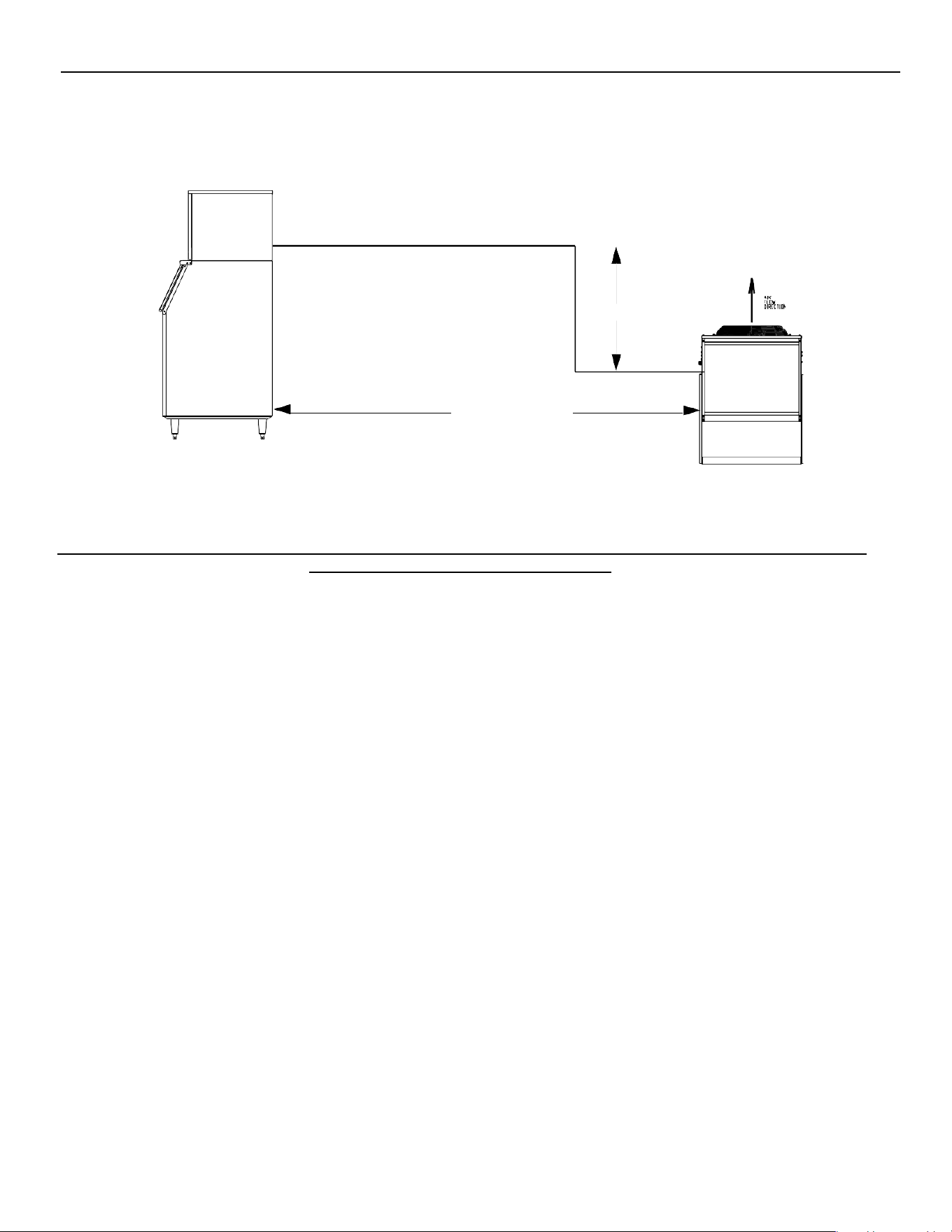
Drop:
(10 ft. x 6.6) + (34 ft.) = 100 calculated feet line run
Example: 10’ x 6.6 + 30’ = 90’ This is < 100 so it is ok.
Configurations that do NOT meet these requirements must receive written authorization from Ice-O-Matic. This includes
multi-pass or rack system remote condensers.
Remote Condenser Location
Pre-charged line sets are available in 25-, 40- or 75-foot lengths to connect the ice machine to the remote
condenser. Select the best available location, protecting the remote condenser from extremes of dirt, dust and
sun. Meet all applicable building codes. The services of a licensed electrician may be required. Clearances
required for the RCA/RGA Condensers are 48” above and 18” on all side of the unit for proper air flow.
Roof Attachment
Install and attach the remote condenser to the roof of the building using the methods and practices of
construction that conform to the local building codes, including having a roofing contractor secure the
remote condenser to the roof.
Have an electrician connect the remote condenser fan motor wires to the ice machine using the junction
box at the back of the machine.
NOTE: REMOTE LINES MUST NOT RISE AND DROP IN THE SAME RUN
Have a roofing contractor cut a minimum hole for the refrigerant lines of 2.50 inch. Check local codes, a
separate hole may be required for the electrical power to the condenser.
CAUTION: DO NOT KINK OR CRIMP REFRIGERANT TUBING WHEN INSTALLING IT.
10 ft. drop
34 ft. horizontal
ELEVATION SERIES CIM CUBERS
REMOTE CONDENSER GUIDELINES
10
Pre-charged Line Set Routing
CAUTION: Do not connect the pre-charged tubing until all routing and forming of the tubing has
been completed. See the coupling instructions for connecting information.
Each set of pre-charged tubing refrigerant lines consists of a 3/8” diameter liquid line and 1/2-inch
diameter discharge line. Both ends of each line have quick connect couplings, one end of the line set has
a Schrader valve connection.
Route refrigerant lines through the roof opening in straight paths when possible. Keep excess tubing inside the
building, spiraling it horizontally to prevent traps. Ensure the roofing contractor seals roof holes according to
local codes.
CAUTION: The couplings on the sets of pre-charged lines are self-sealing when installed properly.
Carefully follow the instructions in the Remote Condenser manual.
Verify all remote components and refrigerant types match before connecting line-
sets. Mixing refrigerants voids the warranty and any related repairs will not be
covered.
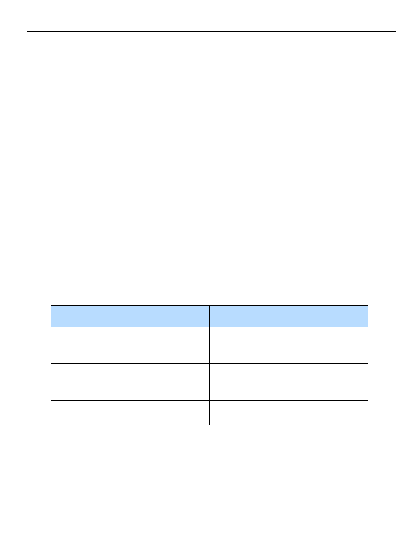
The following remote ice makers incorporate the Mixing Valve in the Condenser. This configuration allows
up to a 100-foot calculated remote line set run. Reference the diagram on the Previous pages to calculate
the maximum 100 ft. line set run. Maximum actual line set run is limited to 75ft.
CIM Machine Model Number
Remote Condenser Model Number
Old/New
CIM0530R
RCA1001/RC100C40/49
CIM0535R
RCA1061/RC106C40/49
CIM0636R
RCA1061/RC106C40/49
CIM0825R/0826R/0835R/0836R/0837R
RCA2061/RC206C40/49
CIM1125R/1126R/1135R/1136R/1137R
RCA2061/RC206C40/49
CIM1446R/1447R
RCA3061/RC306C40/49
CIM1545R/1845R
RCA3061/RC306C40/49
CIM2046R/2047R
RCA3561/RC406C40/49
Verify the CIM machine is compatible with the remote condenser.
For more information contact your Ice-O-Matic distributor.
ELEVATION SERIES
ELECTRICAL AND PLUMBING REQUIREMENTS
11
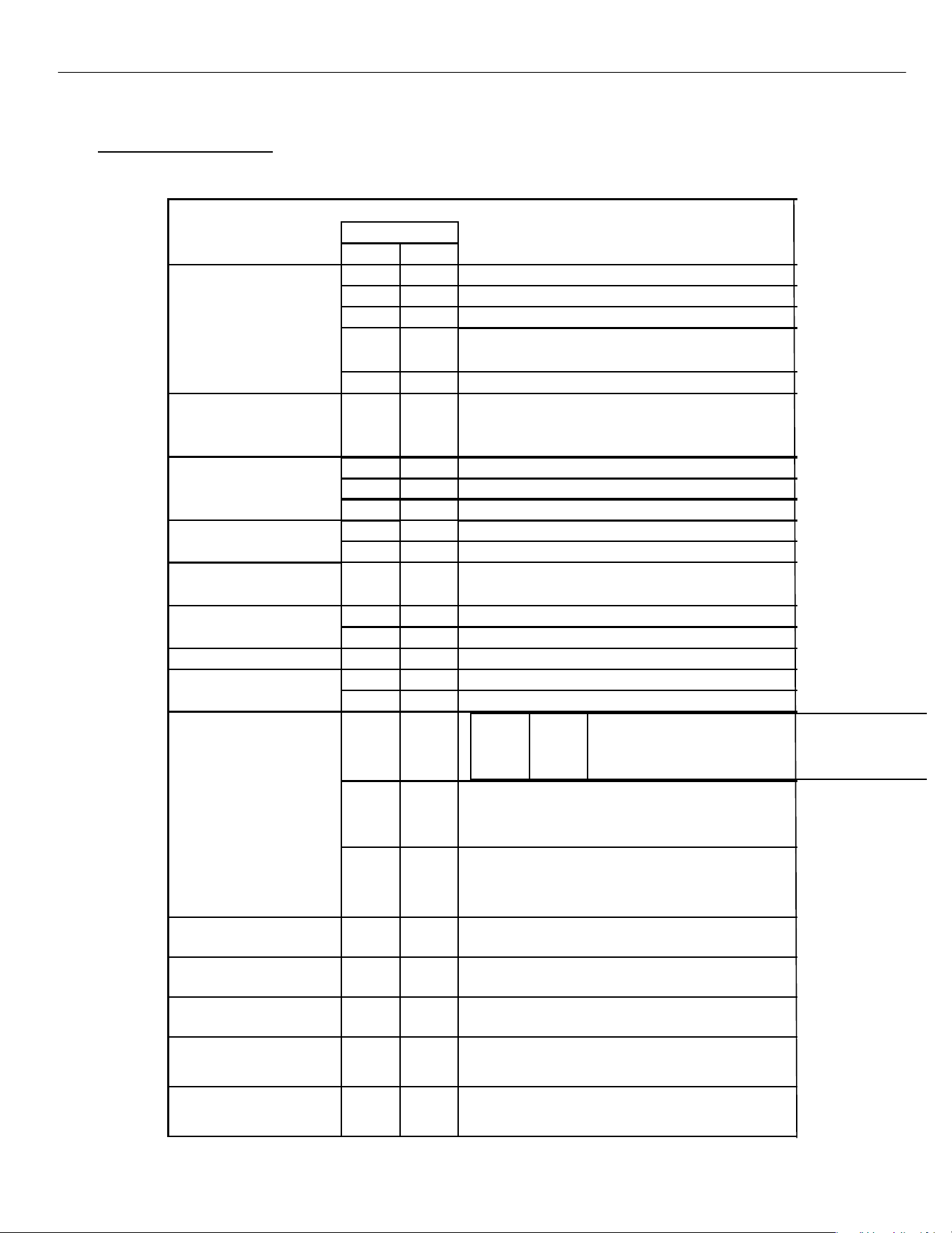
Electrical and Plumbing Requirements
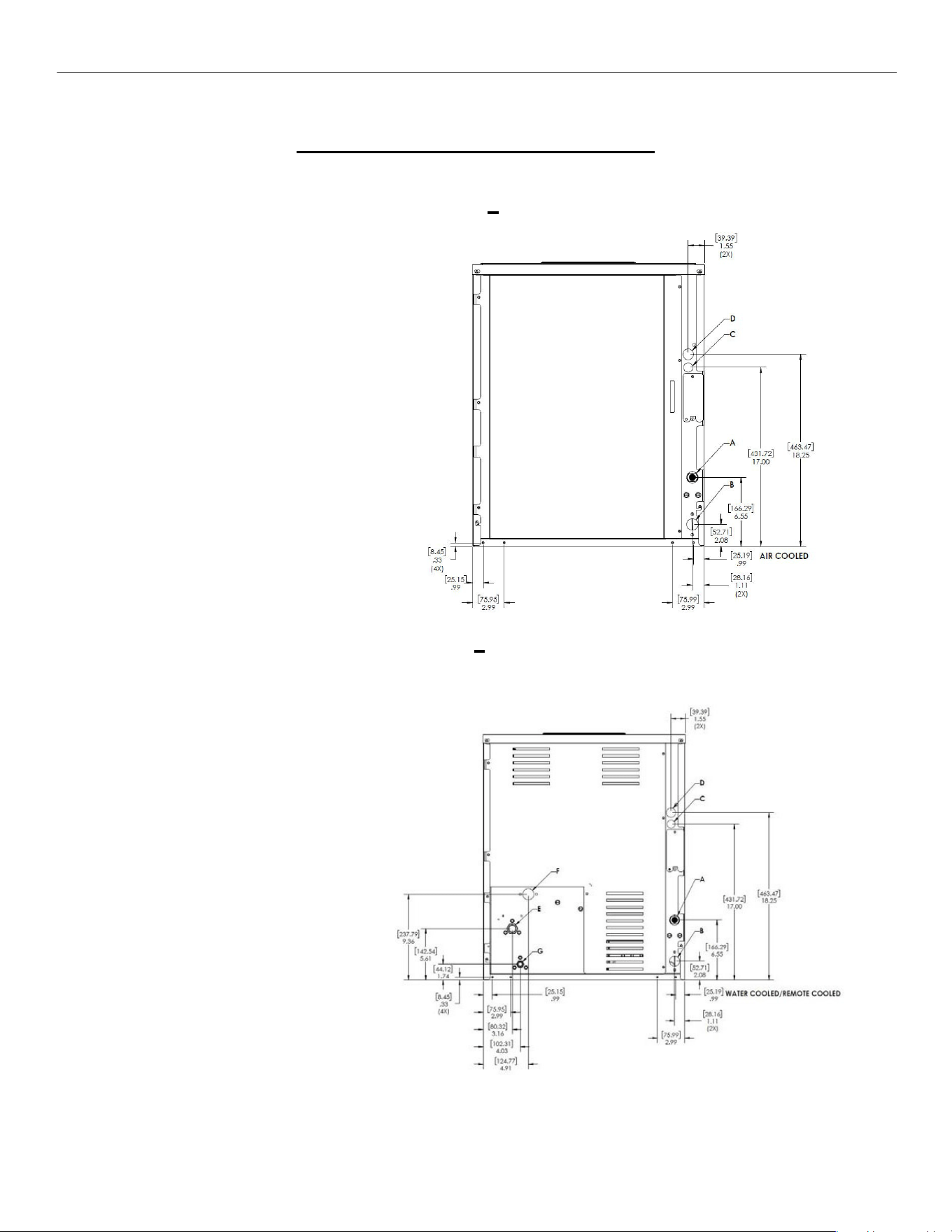
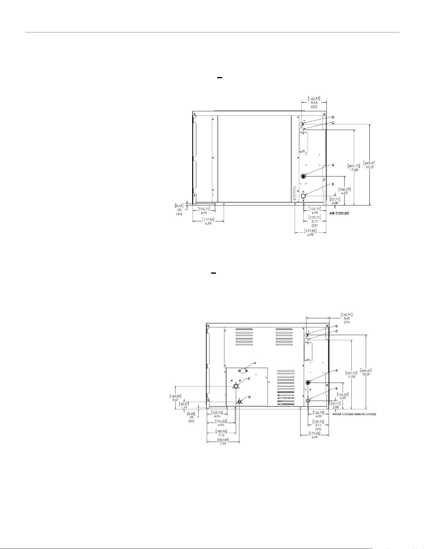
22” CIM SERIES Common Connections
(CIM**2* A)
Air Cooled
Please note: air-cooled units require
6”(152mm) for air intake and exhaust.
A.
Ice maker potable water in,
3/8” FPT.
B.
Ice maker water out,
3/4” FPT.
C.
Hole for electrical connections,
7/8”.
D.
Electrical junction box,
7/8”.
(CIM**2* W/R)
Water/Remote Cooled
A.
Ice maker potable water in,
3/8” FPT.
B.
Ice maker water out,
3/4” FPT.
C.
Hole for electrical connections,
7/8”.
D.
Electrical junction box,
7/8” (remote).
E.
Condenser water in,
3/8” FPT (water only).
Discharge line,
1/2” male quick connect
coupling for pre-charged
line set (remote only).
F.
Condenser water out,
1/2” FPT (water only).
G.
Liquid Line,
3/8” male quick connect
coupling for pre-charged
line set (remote only).
ELEVATION SERIES
ELECTRICAL AND PLUMBING REQUIREMENTS
12
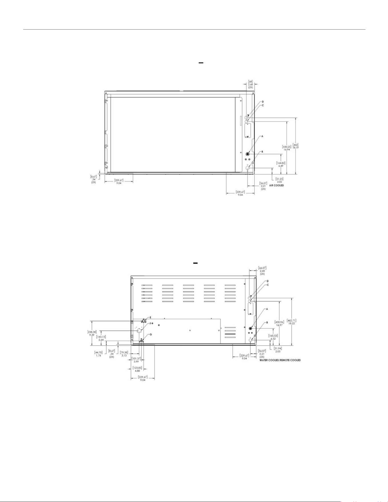
30” CIM SERIES Common Connections
(CIM**3* A)
Air Cooled
Please note: air-cooled units require
6”(152mm) for air intake and exhaust.
A.
Ice maker potable water in,
3/8” FPT.
B.
Ice maker water out,
3/4” FPT.
C.
Hole for electrical connections,
7/8”.
D.
Electrical junction box,
7/8”.
(CIM**3* W/R)
Water/Remote Cooled
A.
Ice maker potable water in,
3/8” FPT.
B.
Ice maker water out,
3/4” FPT.
C.
Hole for electrical connections,
7/8”.
D.
Electrical junction box,
7/8” (remote).
E.
Condenser water in,
3/8” FPT (water only).
Discharge line,
1/2” male quick connect
coupling for pre-charged
line set (remote only).
F.
Condenser water out,
1/2” FPT (water only).
G.
Liquid Line,
3/8” male quick connect
coupling for pre-charged
line set (remote only).
ELEVATION SERIES
ELECTRICAL AND PLUMBING REQUIREMENTS
13
Air
48” CIM SERIES Common Connections
(CIM**4* A)
Please note: air-cooled units require 6”(152mm) for air intake and exhaust.
A.
Ice maker potable water in,
3/8” FPT.
B.
Ice maker water out,
3/4” FPT.
C.
Hole for electrical connections,
7/8”.
D.
Electrical junction box,
7/8”.
(CIM**4* W/R)
Water/Remote Cooled
A.
Ice maker potable water in,
3/8” FPT.
B.
Ice maker water out,
3/4” FPT.
C.
Hole for electrical connections,
7/8”.
D.
Electrical junction box,
7/8” (remote).
E.
Condenser water in, 3/8” FPT (water only).
Discharge line, 1/2” male quick connect
coupling for pre-charged line set (remote only).
F.
Condenser water out,
3/4” FPT (water only).
G.
Liquid Line,
3/8” male quick connect coupling for
pre-charged line set (remote only).
ELEVATION SERIES
START-UP PROCEDURE
14
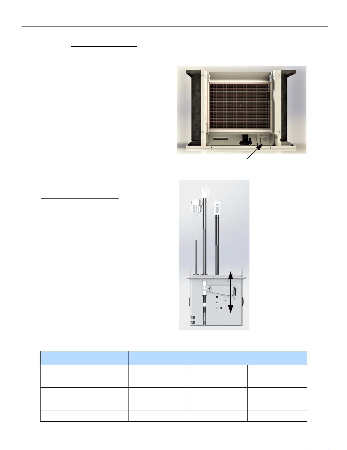
Start-Up Procedure
Note: Before starting the machine, make sure the
machine is level within 1/8 inch in all directions,
the bin or dispenser leg height can be adjusted by
rotating the leg foot
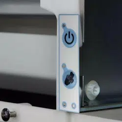
After verifying proper voltage, water supply, drains
and breathable air space around the unit, press and
quickly release the ON/OFF button behind the unit
front panel. The indicator light will change from a
solid red to solid blue in color.
Follow the sequence of operation described under
“Operation of CIM Series Cuber” in this manual.
Check the operation of each component through
the cycle as explained in this section.
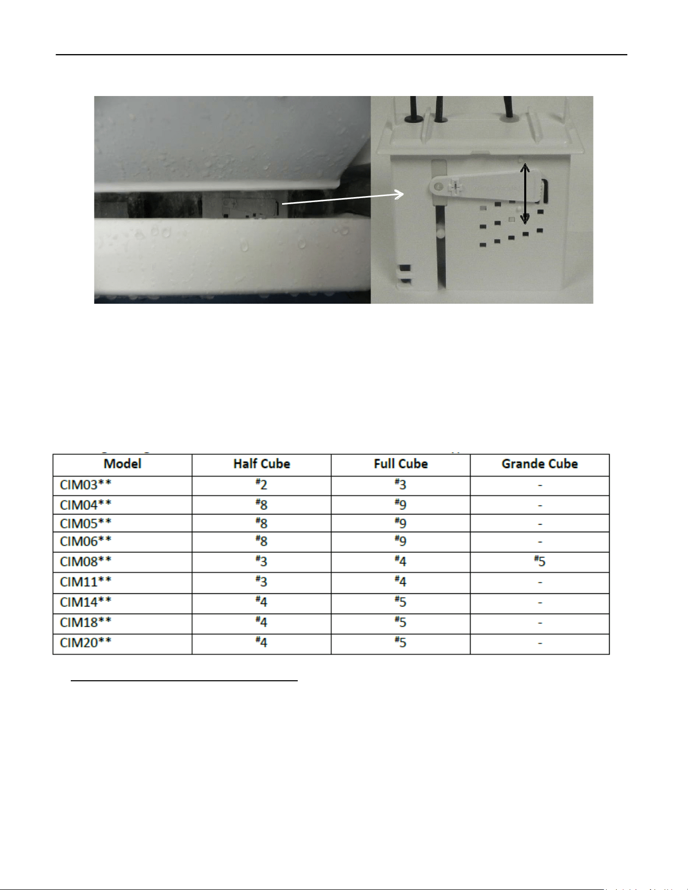
Bridge Thickness Adjustment
Once the unit has gone through a harvest cycle,
verify the bridge thickness (3/16” thick for units
less than 400 lbs. and 1/8” for 400 lbs. and above)
across the middle of the ice slab on the second
batch produced. The ice thickness can be changed
on the Float Housing by turning the adjustment
clockwise to decrease the bridge thickness and
counterclockwise to increase the bridge thickness.
You will hear a “click” with each adjustment. It is
recommended adjustments be made one or two
“clicks” at a time.
Access to Water Level Adjustment
Raising lever
increases bridge
thickness
Lowering lever
decreases bridge
thickness
Batch weights for each model
Model Batch Weight
Half Cube
Full Cube
Grande Cube
CIM0320/0330
2.9-3.15
3.25-3.5
-
CIM0430/0520/0530/0636
4.9-5.15
5.5-5.8
-
CIM0826/0836/1126/1136
6.9-7.4
7.9-8.3
8.4-8.8
CIM1446/1545/2046/2047
13.8-14.8
15.8-16.6
-
ELEVATION SERIES CIM CUBERS
SEQUENCE OF OPERATIONS
15
Sequence of Operations
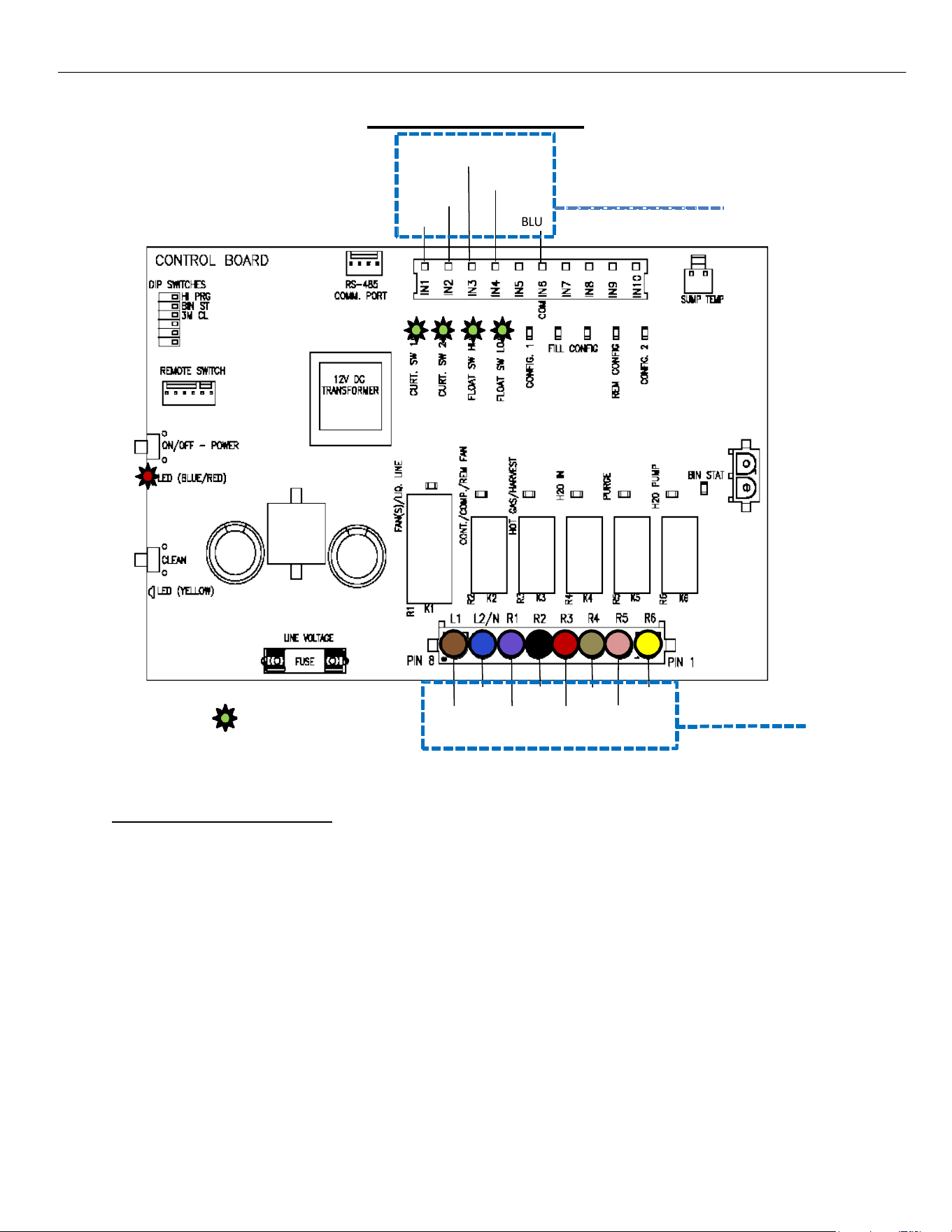
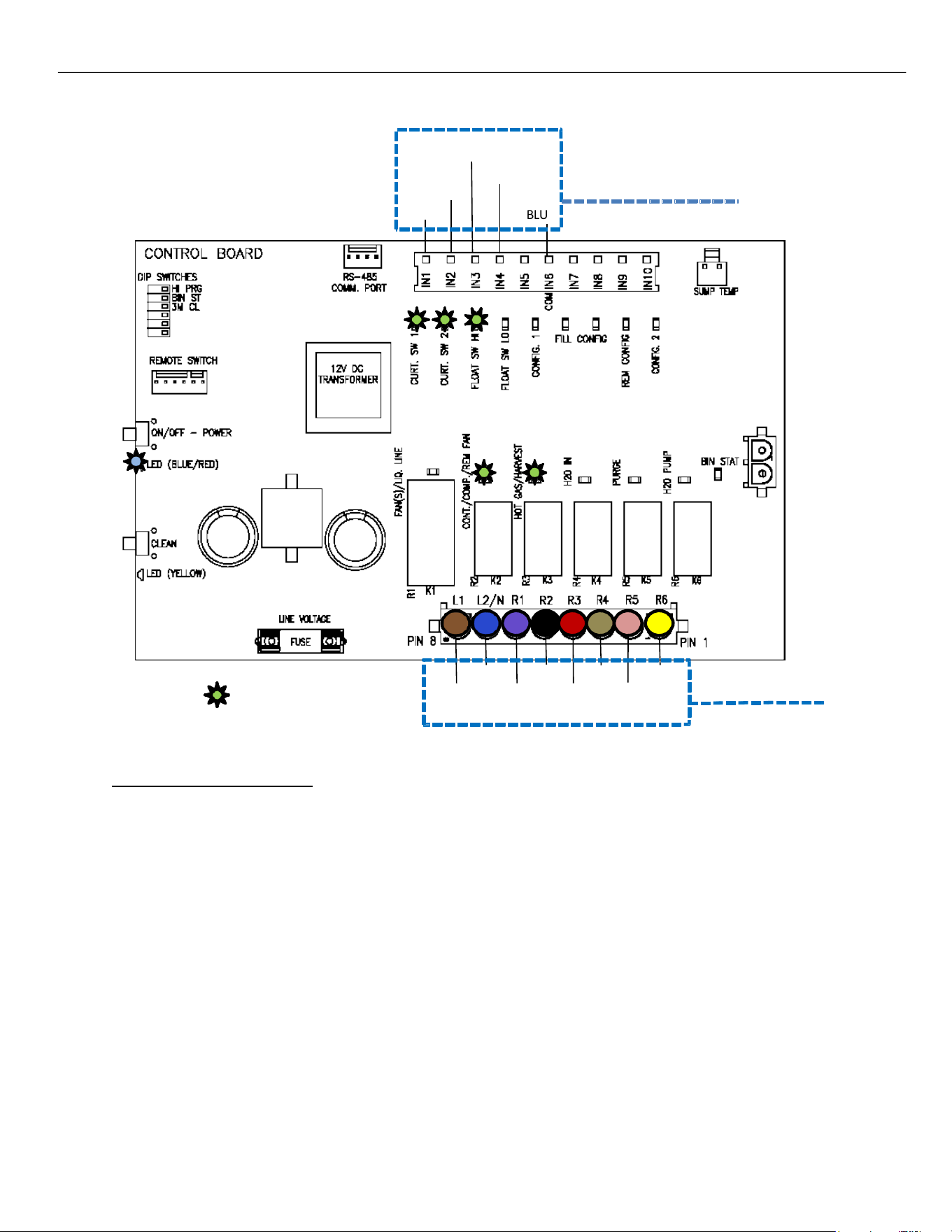
CONTROL BOARD - OFF STATUS
When power is initially applied to the unit, the LED’s on both the Push Pad and the Board POWER Button
will flash in sequence BLUE, then RED, then the WASH Button will flash YELLOW, followed by the POWER
Button LED will turn a solid RED, indicating the unit is in the OFF status as shown above.
The LEDs for the Curtain Switches (1 & 2), High Float Switch and Low Float Switch will be illuminated
Indicating closed circuits. Should the Curtains or Bin Thermostat (if installed) be open, the unit will not
start a Freeze Cycle.
From an OFF status, the unit can start a CLEAN cycle, a FREEZE cycle or be put in the DIAGNOSTIC mode.
For Cleaning Instructions, see page 56. For more on the DIAGNOSTIC mode see page 36.
12V DC Switches
BLUE
R1
= Illuminated LED
BLUE BLACK TAN
BROWN VIOLET RED
YELLOW
PINK
Line Voltage
Components
BLUE w/ WHITE
BLUE w/ RED
WHITE
WHITE
R2 R3 R4 R5 R6
ELEVATION SERIES CIM CUBERS
SEQUENCE OF OPERATIONS
16
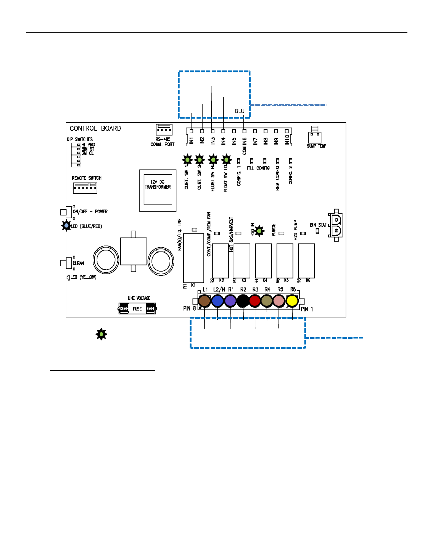
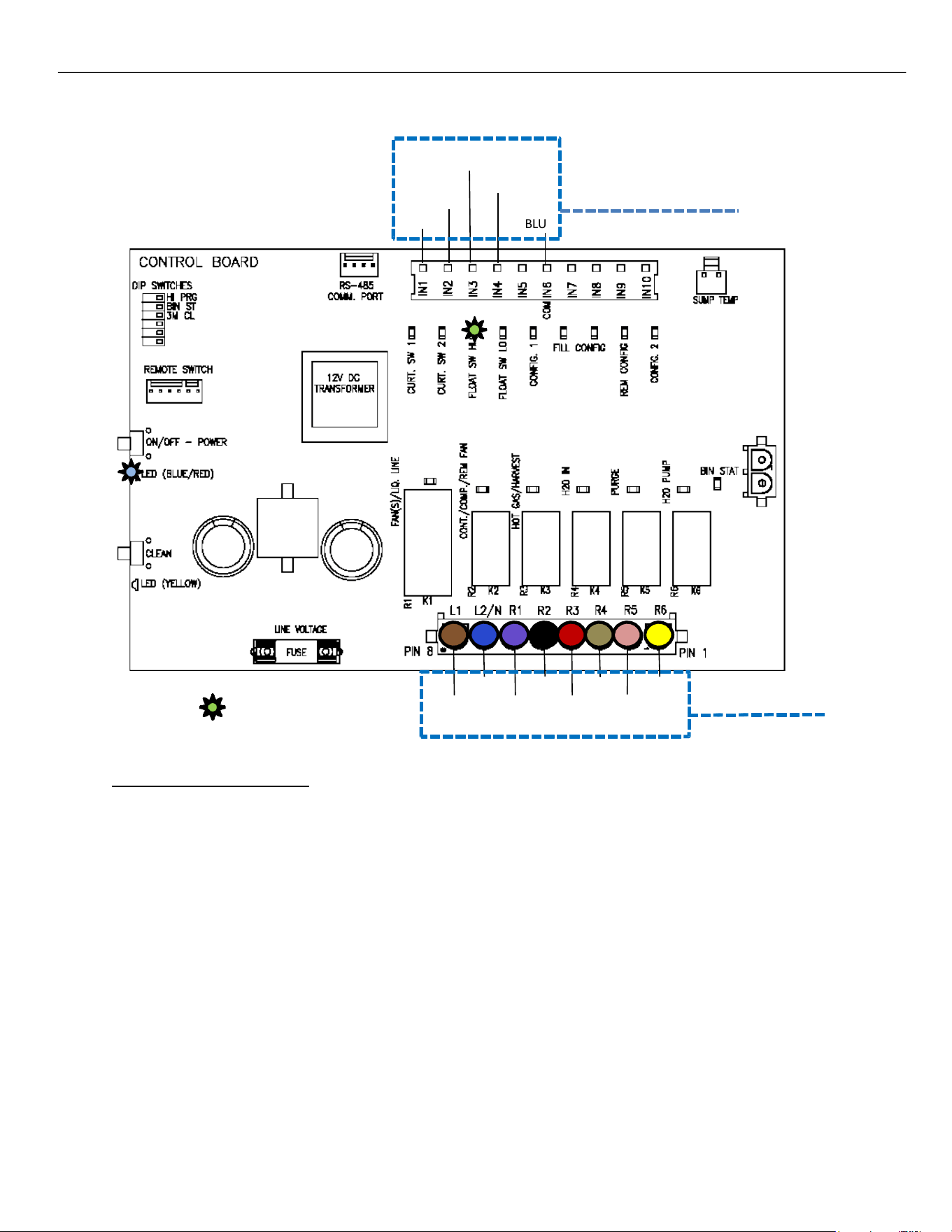
CONTROL BOARD - FREEZE CYCLE
To start the Freeze cycle, briefly press the POWER button on the Membrane Switch or Board. This opens the
Water Inlet Valve (shown by the R4 LED), letting water flow into the Sump. As the water rises, the Low‐Water
Float opens and turns off its Switch LED, and when the High‐Water Float opens also turns off its LED, the Water
Inlet Valve closes, and the R4 LED goes off.
Note: Minimum Freeze Cycle ‐ 5 minutes (from Compressor Start.)
Maximum Freeze Cycle ‐ 1 hour.
Maximum fill time‐ 5 minutes
12V DC Switches
BLUE
R1
= Illuminated LED
BLUE BLACK TAN
BROWN VIOLET RED
YELLOW
PINK
Line Voltage
Components
BLUE w/ WHITE
BLUE w/ RED
WHITE
WHITE
R2 R3 R4 R5 R6
ELEVATION SERIES CIM CUBERS
SEQUENCE OF OPERATIONS
17
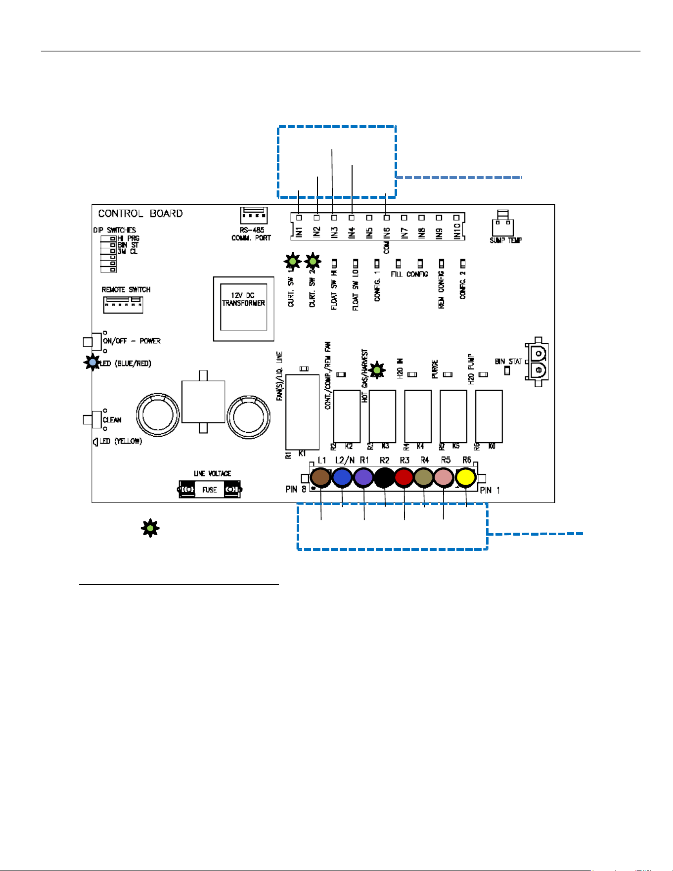
CONTROL BOARD - COMPRESSOR START
The Hot Gas Valve will be energized (R3 on Board illuminated) for 5 seconds and the system pressures will
start to equalize.
BLUE w/ WHITE
BLUE w/ RED
WHITE
WHITE
12V DC Switches
BLUE
R1
= Illuminated LED
BLUE BLACK TAN
BROWN VIOLET RED
YELLOW
PINK
Line Voltage
Components
R2 R3 R4 R5 R6

ELEVATION SERIES CIM CUBERS
SEQUENCE OF OPERATIONS
18
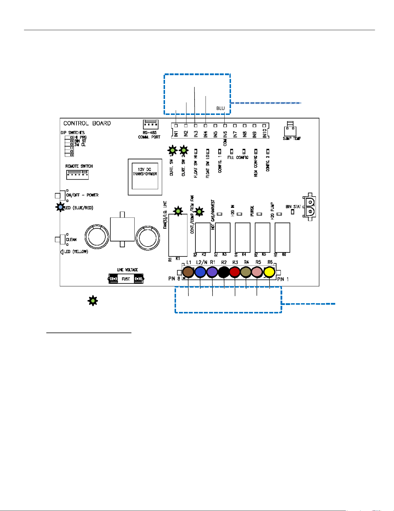
CONTROL BOARD - COMPRESSOR START
The Compressor will be energized (R2 on Board illuminated) and the Hot Gas Valve will remain open for 5
more seconds and then de‐energize (R3 on Board off).
BLUE w/ WHITE
BLUE w/ RED
WHITE
WHITE
12V DC Switches
BLUE
R1
= Illuminated LED
BLUE BLACK TAN
BROWN VIOLET RED
YELLOW
PINK
Line Voltage
Components
R2 R3 R4 R5 R6
ELEVATION SERIES CIM CUBERS
SEQUENCE OF OPERATIONS
19
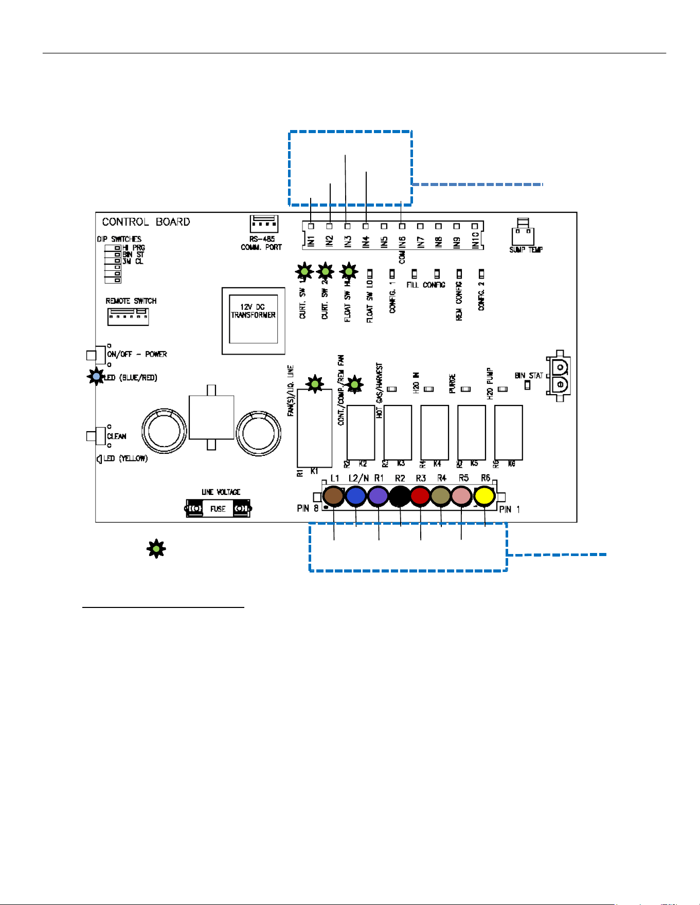
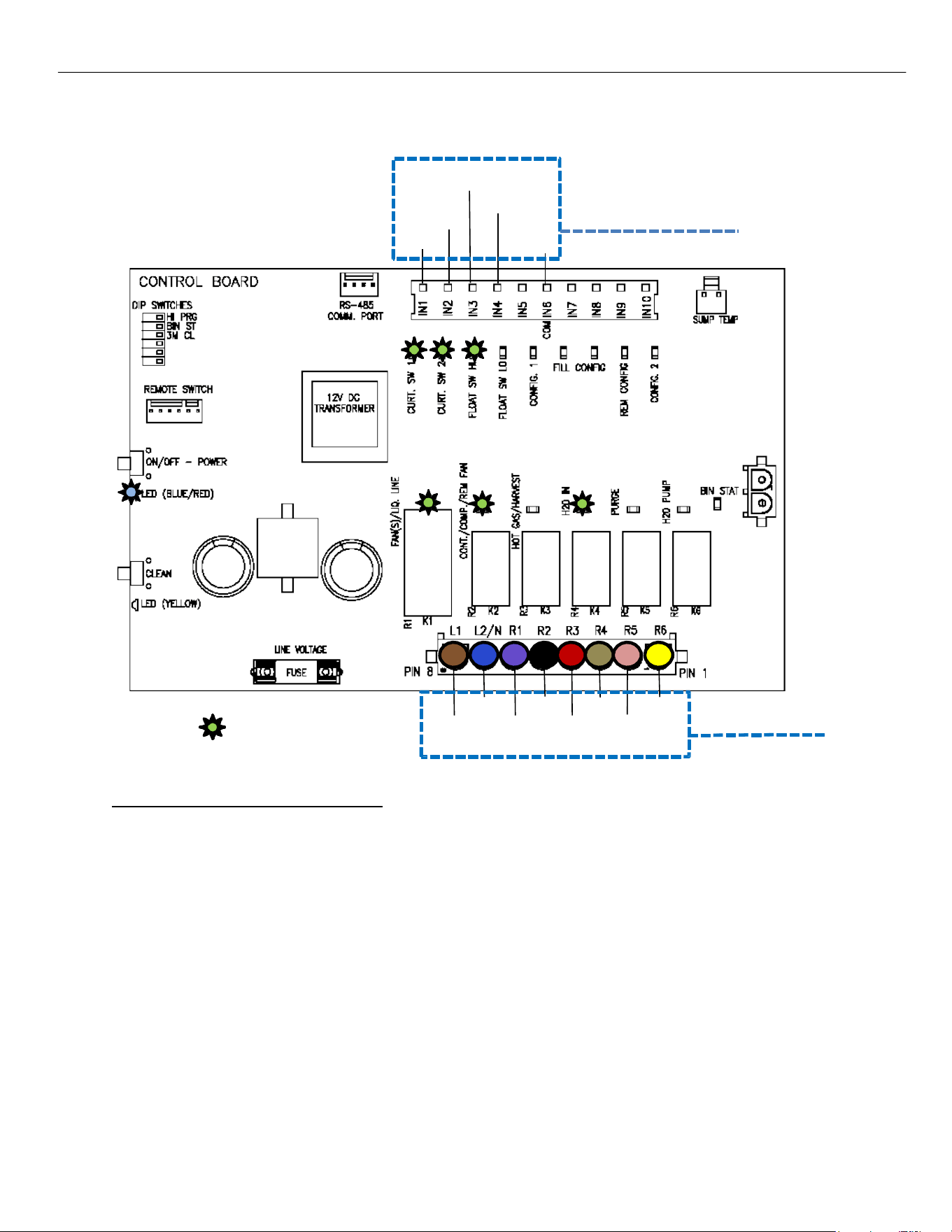
CONTROL BOARD - PRE-CHILL
The Compressor and Fan(s)/Liquid Line Solenoid (R1 and R2 LEDs on Board illuminated) are energized
and unit is now in a Pre‐Chill for 30 seconds bringing the Evaporator temperature down. Both Curtain
Switch LEDs are on showing closed curtain(s). On the Self‐contained units, (R1) is energized the Fan
Motor will only come on once the Fan Cycle Switch closes at 250 psi of head pressure. (if fan cycle switch
is not bypassed.)
12V DC Switches
BLUE
R1
= Illuminated LED
BLUE BLACK TAN
BROWN VIOLET RED
YELLOW
PINK
Line Voltage
Components
BLUE w/ WHITE
BLUE w/ RED
WHITE
WHITE
R2 R3 R4 R5 R6

ELEVATION SERIES CIM CUBERS
SEQUENCE OF OPERATIONS
20
CONTROL BOARD - FREEZE
The Water Pump is energized (R6 LED on Board illuminated) and water is pushed through the Water
Pump Tube and flows over the Evaporator. The High Float Switch contacts close as the water level in the
Sump drops (High Float Switch LED on Board illuminates). Should this not happen Error 7 will occur.
BLUE w/ WHITE
BLUE w/ RED
WHITE
WHITE
12V DC Switches
BLUE
R1
= Illuminated LED
BLUE BLACK TAN
BROWN VIOLET RED
YELLOW
PINK
Line Voltage
Components
R2 R3 R4 R5 R6
ELEVATION SERIES CIM CUBERS
SEQUENCE OF OPERATIONS
21
CONTROL BOARD - ANTI-SLUSH
When the water temperature reaches 38 degrees F. the Water Pump will shut off for 20 seconds to
reduce the possibility of slush developing in the Sump.
BLUE w/ WHITE
BLUE w/ RED
WHITE
WHITE
12V DC Switches
BLUE
R1
= Illuminated LED
BLUE BLACK TAN
BROWN VIOLET RED
YELLOW
PINK
Line Voltage
Components
R2 R3 R4 R5 R6
ELEVATION SERIES CIM CUBERS
SEQUENCE OF OPERATIONS
22
CONTROL BOARD - WATER PUMP ON
At the end of Anti‐Slush, the Water Pump (R6) will be re‐energized, and water starts flowing over the
Evaporator again continuing Freeze mode. The unit will stay in Freeze mode (minimum of 5 min) until the Low
Float Switch closes on water level drop (units below 800lbs), or after the second fill on units over 800lbs
indicating the unit is ready to harvest.
BLUE w/ WHITE
BLUE w/ RED
WHITE
WHITE
12V DC Switches
BLUE
R1
= Illuminated LED
BLUE BLACK TAN
BROWN VIOLET RED
YELLOW
PINK
Line Voltage
Components
R2 R3 R4 R5 R6
ELEVATION SERIES CIM CUBERS
SEQUENCE OF OPERATIONS
23
CONTROL BOARD - INITIATING HARVEST
When the water level in the SUMP drops to close the contacts of the Low Float Switch (LED on Board
illuminates) after a 5 second Delay of the Low float switch closing it will signal the start of the Harvest Cycle.
BLUE w/ WHITE
BLUE w/ RED
WHITE
WHITE
12V DC Switches
BLUE
R1
= Illuminated LED
BLUE BLACK TAN
BROWN VIOLET RED
YELLOW
PINK
Line Voltage
Components
R2 R3 R4 R5 R6
ELEVATION SERIES CIM CUBERS
SEQUENCE OF OPERATIONS
24
CONTROL BOARD - HARVEST
Once in the Harvest, the R2‐R6 relays send power to the Hot Gas Valve, Harvest Assist, Purge Valve, and Water
Inlet Valve (R2, R3, R4, R5, and R6 are illuminated on Air‐ and Water‐Cooled units; all relays are energized on
Remote units).
CONTROL BOARDS
(after Jan 2023)
If the Harvest Time reaches 5 minutes, the Water Pump activates to assist in the harvest process.
NOTE: Minimum harvest time is 20 seconds.
Pre serial number 2106 control boards have a 5 min maximum harvest time.
Post serial number 2106 control boards The maximum harvest time is 7.5 minutes.
BLUE w/ WHITE
BLUE w/ RED
WHITE
WHITE
12V DC Switches
BLUE
R1
= Illuminated LED
BLUE BLACK TAN
BROWN VIOLET RED
YELLOW
PINK
Line Voltage
Components
R2 R3 R4 R5 R6
ELEVATION SERIES CIM CUBERS
SEQUENCE OF OPERATIONS
25
CONTROL BOARD - HARVEST
After the Purge Valve and Water Pump de‐energize, the Water Inlet Valve will remain open for 20
seconds partially filling the SUMP in preparation for the next Freeze Cycle (R2, R3, and R4, are
illuminated on Air‐ and Water‐Cooled units, R1 is also energized on Remotes.) The Low Float Switch will
go off as the water level rises.
BLUE w/ WHITE
BLUE w/ RED
WHITE
WHITE
12V DC Switches
BLUE
R1
= Illuminated LED
BLUE BLACK TAN
BROWN VIOLET RED
YELLOW
PINK
Line Voltage
Components
R2 R3 R4 R5 R6
ELEVATION SERIES CIM CUBERS
SEQUENCE OF OPERATIONS
26
CONTROL BOARD - HARVEST
After the Water Inlet Valve closes following the 20 second time out, the Hot Gas Valve and Harvest Assist
will remain energized until the ice slab is harvested from the Evaporator. At this point the unit is reading
the Curtain Switch (s) and/or Bin Thermostat (if added).
12V DC Switches
BLUE
R1
= Illuminated LED
BLUE BLACK TAN
BROWN VIOLET RED
YELLOW
PINK
Line Voltage
Components
BLUE w/ WHITE
BLUE w/ RED
WHITE
WHITE
R2 R3 R4 R5 R6
ELEVATION SERIES CIM CUBERS
SEQUENCE OF OPERATIONS
27
CONTROL BOARD - BIN FULL
When ice drops from the Evaporator, the Curtain switch opens. If it stays open for 30 seconds, the unit shuts
down as the bin is full, turning off all RELAY LEDs (R1–R6). If the bin isn't full, the next cycle begins. Refer to page
28.
If the unit turns off due to a full bin or because the Bin Thermostat stays open for 90 seconds, it won't restart
for 3 minutes to prevent compressor short cycling. Showing a slow Blue flashing light on the Display.
12V DC Switches
BLUE
R1
= Illuminated LED
BLUE BLACK TAN
BROWN VIOLET RED
YELLOW
PINK
Line Voltage
Components
BLUE w/ WHITE
BLUE w/ RED
WHITE
WHITE
R2 R3 R4 R5 R6
ELEVATION SERIES CIM CUBERS
SEQUENCE OF OPERATIONS
28
CONTROL BOARD - RETURN TO FREEZE
As the ice slab drops from the Evaporator, it moves the Curtain(s), which makes the Curtain Switch contacts
open and close, ending the Harvest Cycle. If both the Curtain and the Bin Thermostat (if installed) are closed,
the system starts the Freeze Cycle. During this phase, the Compressor (R2) and Fan(s) (R1) keep running, while
the Water Inlet Valve (R4) turns on to fill the Sump until the High‐Water Float opens de‐energizing the water
valve.
BLUE w/ WHITE
BLUE w/ RED
WHITE
WHITE
12V DC Switches
BLUE
R1
= Illuminated LED
BLUE BLACK TAN
BROWN VIOLET RED
YELLOW
PINK
Line Voltage
Components
R2 R3 R4 R5 R6
ELEVATION SERIES CIM CUBER
CONTROL BOARD
29
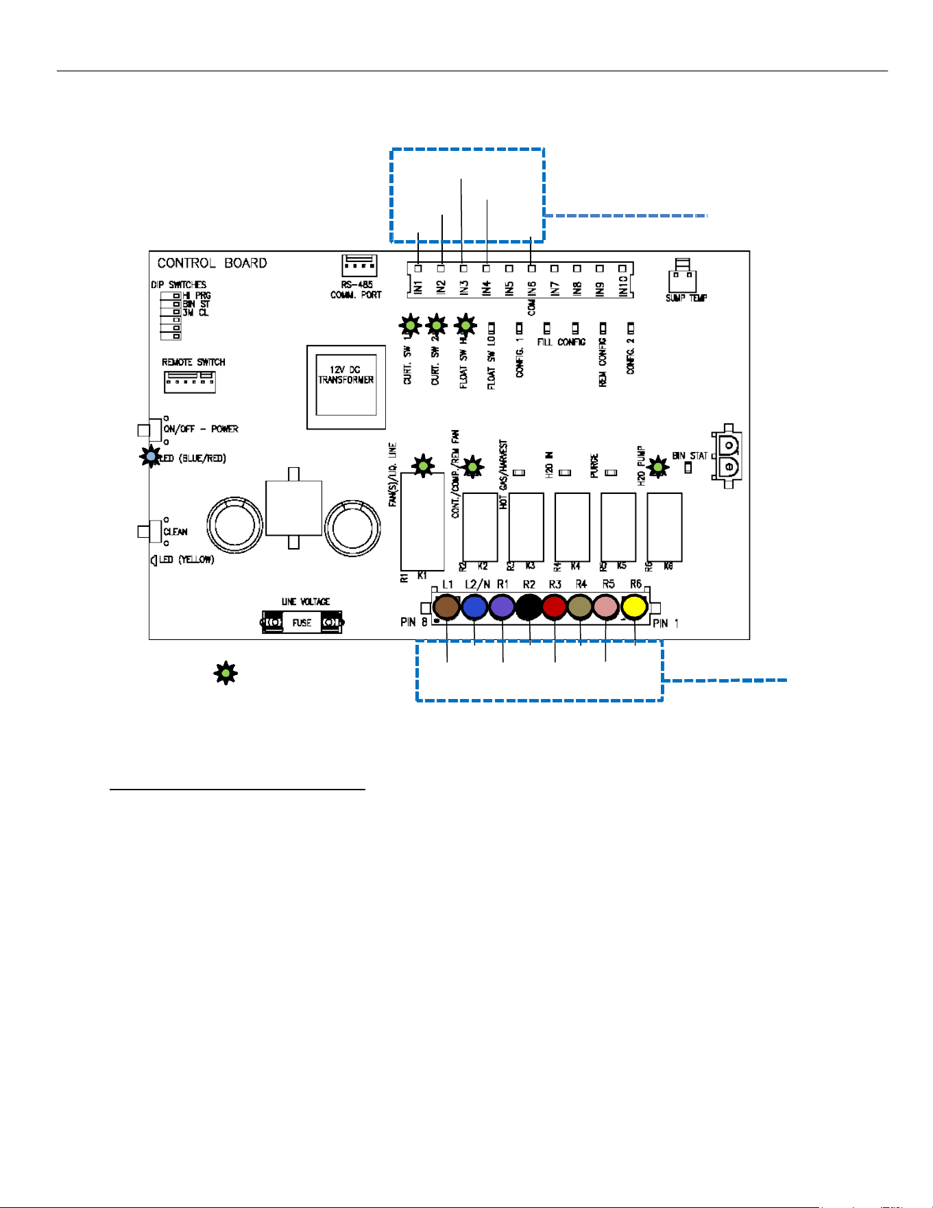
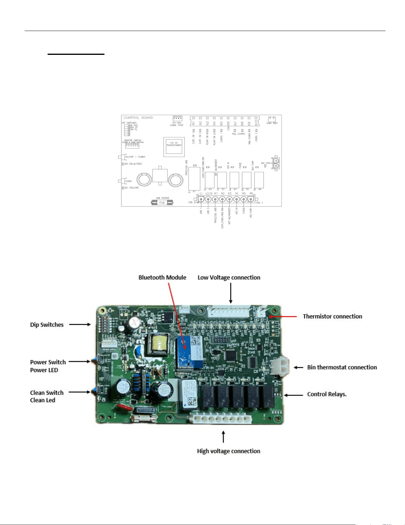
Control Board
Operation
The Board controls the operation of the unit. A series of LED lights show Switch positions and
Component operation to assist the technician in understanding and troubleshooting issues that
may arise. See Sequence of Operation pg. 9 for operational information.
Control Board Features

ELEVATION SERIES CIM CUBER
CONTROL BOARD
30
Adjustment Switch Block
Four adjustments can be made on the block. Extended Purge, Bin Thermostat Kit add-on and
Cleaning Needed Reminder.
Standard Purge time during a Defrost Cycle is set at 7 seconds. To add an additional 40 seconds
to the purge time, move Switch 1 to the right, to the ON position.
Should the unit be installed on top of a dispenser, a Bin Thermostat Kit is required. Following the
instruction that comes with the kit, switch 2 needs to be moved to the ON position to tell the pro-
gram to read the Bin Thermostat. The LED beside the Bin Stat Connection will then illuminate.
Switch 3 on the block is for the Cleaning Needed Reminder. When in the OFF position, the
default setting for the clean reminder is 6 months. When Switch 3 is moved to the ON position,
the Reminder is set for every 3 months. This is recommended should the unit be installed in a
hardwater location to help with production levels. Switch 4 turns off the clean reminder light.
(not recommended).
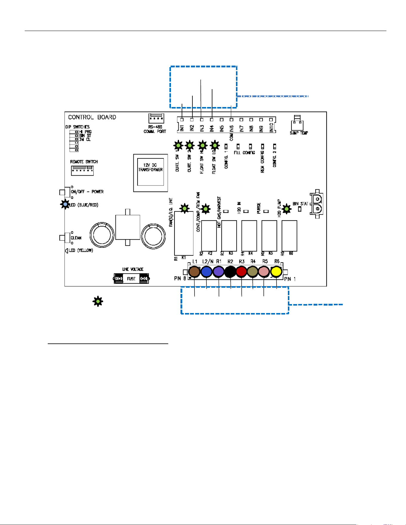
Low Voltage connection (12VDC) for Control Switches
This Molex connects the Magnetic Curtain Switch(es), High Float Switch, Low Float Switch and
Remote Configuration Switch to the Board. The LED’s associated to each switch will illuminate
when the contacts for each are closed. The Remote Configuration LED will be illuminated when
the Smart Harness reads the unit has a Remote Condenser. The fill light indicates unit is over 800lbs
and has to fill 2 times with water. Config1 (D2), (D16),and (D17) are not used.
Thermistor Connection
The Thermistor is used to gauge the water temperature in the Sump and is used to activate the
Anti-Slush Cycle. When the water temperature reaches 36 degrees F during the first 3 cycles
following a full bin situation, being restarted after a loss of power or turned off, the Water Pump
will be turned off for 20 seconds to help prevent slushing of the water in the Sump. An Anti-Slush
will also be performed any time the water temperature reaches 28 degrees F. Control Boards
after ser. 2106 Shuts down the pump at 38° F for 20 seconds every cycle.
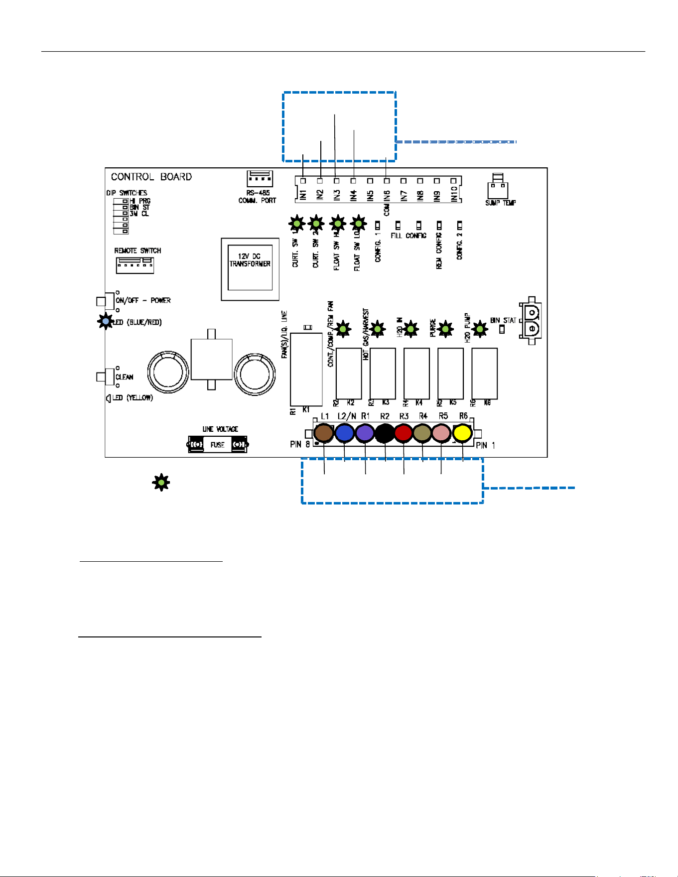
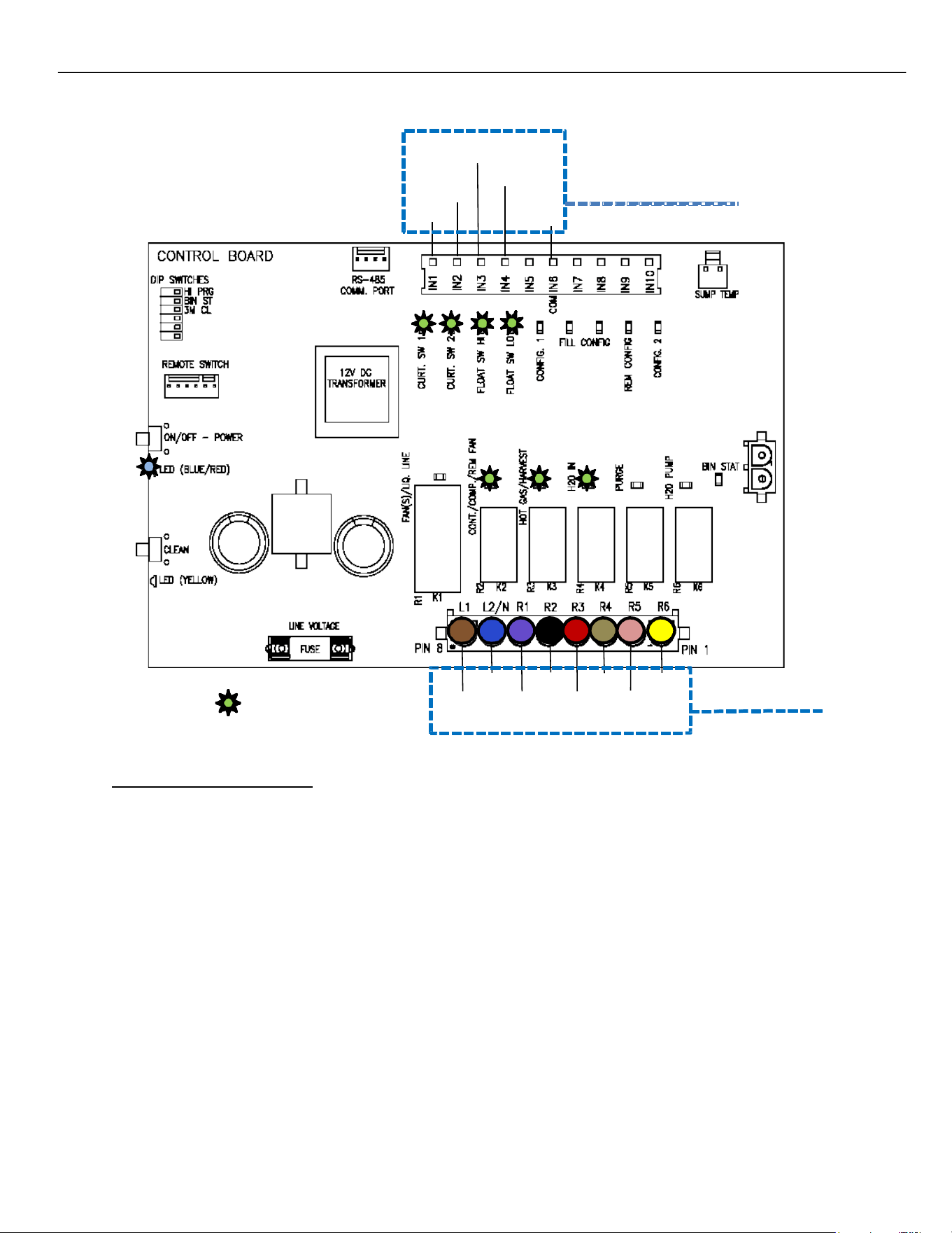
Control Relays
The six Control Relays send voltage out to the individual components during the operation of the
unit. Relay 1 energizes the Fan(s) on self-contained air-cooled units or the Liquid Line Solenoid
on Remotes. Relay 2 energizes the Compressor through the Contactor (and Fan Motor on
Remotes). Relay 3 energizes the Hot Gas Valve and Harvest Assist Assembly during the Harvest
Cycle. Relay 4 energizes Water Inlet Valve. Relay 5 energizes the Purge Valve. Relay 6 energizes
the Water Pump.
Line Voltage Connection
The Line Voltage Molex connects each component to the Board. See the wiring diagram for each
unit to see the wiring colors associated with each component.
Power and Clean Buttons
These buttons are functional duplicates of the buttons on the Push Pad mounted to the front frame
of the unit. See also “Button Function” chart in this manual for operation.
Bluetooth Module
This allows a connection to the controller via Ice-O-Matic’s Mobile app to help see the control
board function. Downloadable on your Mobile app store.

ELEVATION SERIES CIM CUBER
CONTROL BOARD
31
Power and Clean LED Flash Description
SOLID - On Constantly
SLOW - Flashes once every second
QUICK - Flashes once every half second
DOUBLE - Flashes twice then 1 second delay
TRIPLE- Flashes Three times then 1second delay
DELAYED - flashes once every 3 seconds
Error Codes
Error 1 - POWER LED QUICK FLASH RED - Unit has experienced a MAX Freeze (1 hr.), on (Boards
Pre 2106 ser. Only) MAX Harvest (5.5 minutes) or BOTH.
Error 2 - POWER LED SLOW FLASH IN OFF STATE ONLY - Thermistor Failure.
Error 3: POWER LED flashes red and CLEAN LED flashes yellow quickly. The unit experienced a
MAX Fill (5 min) Current production. Previously was Max Fill and/ or Max Purge Pre 2106 Serial
Error 4 – DOUBLE RED AND DOUBLE YELLOW QUICK FLASH – Unit has experienced a MAX
Purge (2 min.)
Error 5 – DOUBLE RED QUICK FLASH – Unit has Experienced a MAX Harvest (7.5 min)
Error 6 – TRIPLE RED QUICK FLASH – Unit has experienced MAX Freeze (1 hr.) and Max Harvest,
(7.5 min)
Error 7 – TRIPLE RED AND TRIPLE YELLOW QUICK FLASH – Unit has experienced a Water
Level Error (float did not close)
Minimum / Maximum Times
Freeze - 5 Minute Minimum / 1 Hour Maximum
Standard Harvest - 20 Second Minimum / 7.5 Minute Maximum
Current production. Previous was 5 minute Maximum boards prior to
2106
Water Fill - No Minimum / 5 Minute Maximum
Purge - 7 Second Minimum / 2 Minute Maximum
ELEVATION SERIES CIM CUBERS
BOARD COMPONENT LED SEQUENCE
32
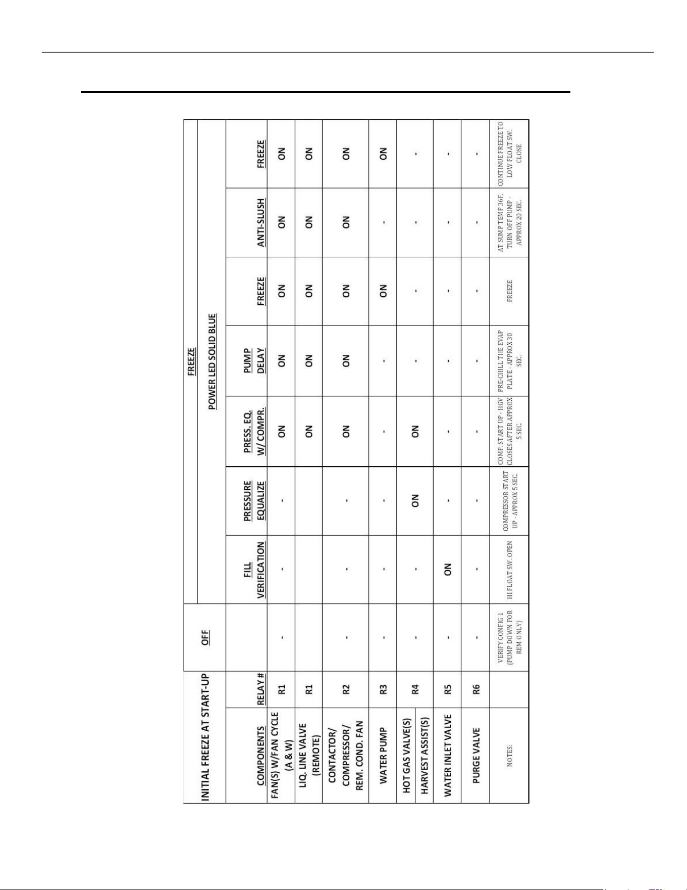
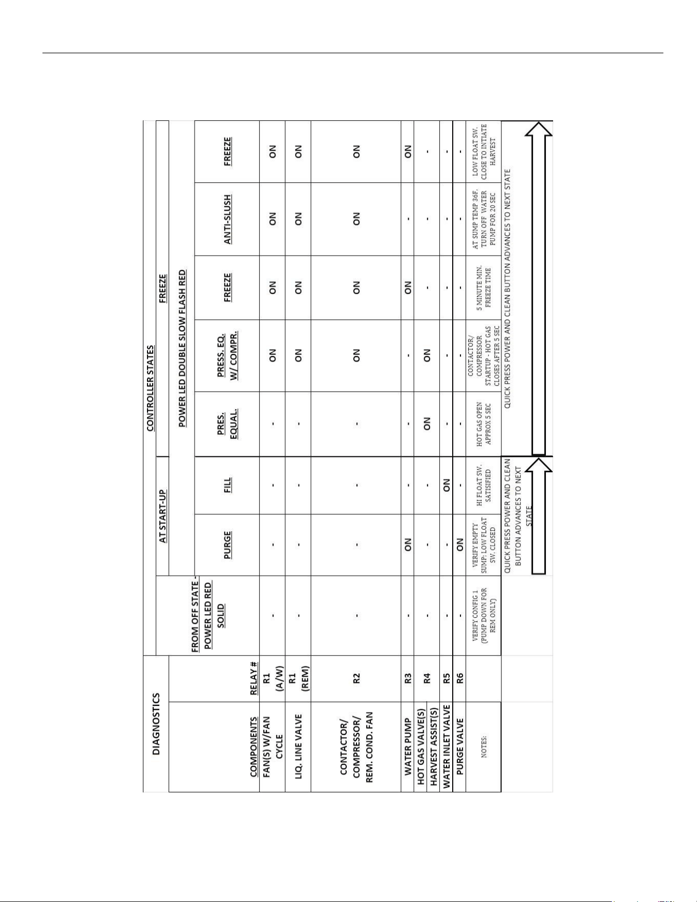
Board Led Sequence During Operation Test Control Boards to Serial 2106
INITIAL FREEZE CYCLE AT START-UP
ELEVATION SERIES CIM CUBERS
BOARD COMPONENT LED SEQUENCE
33
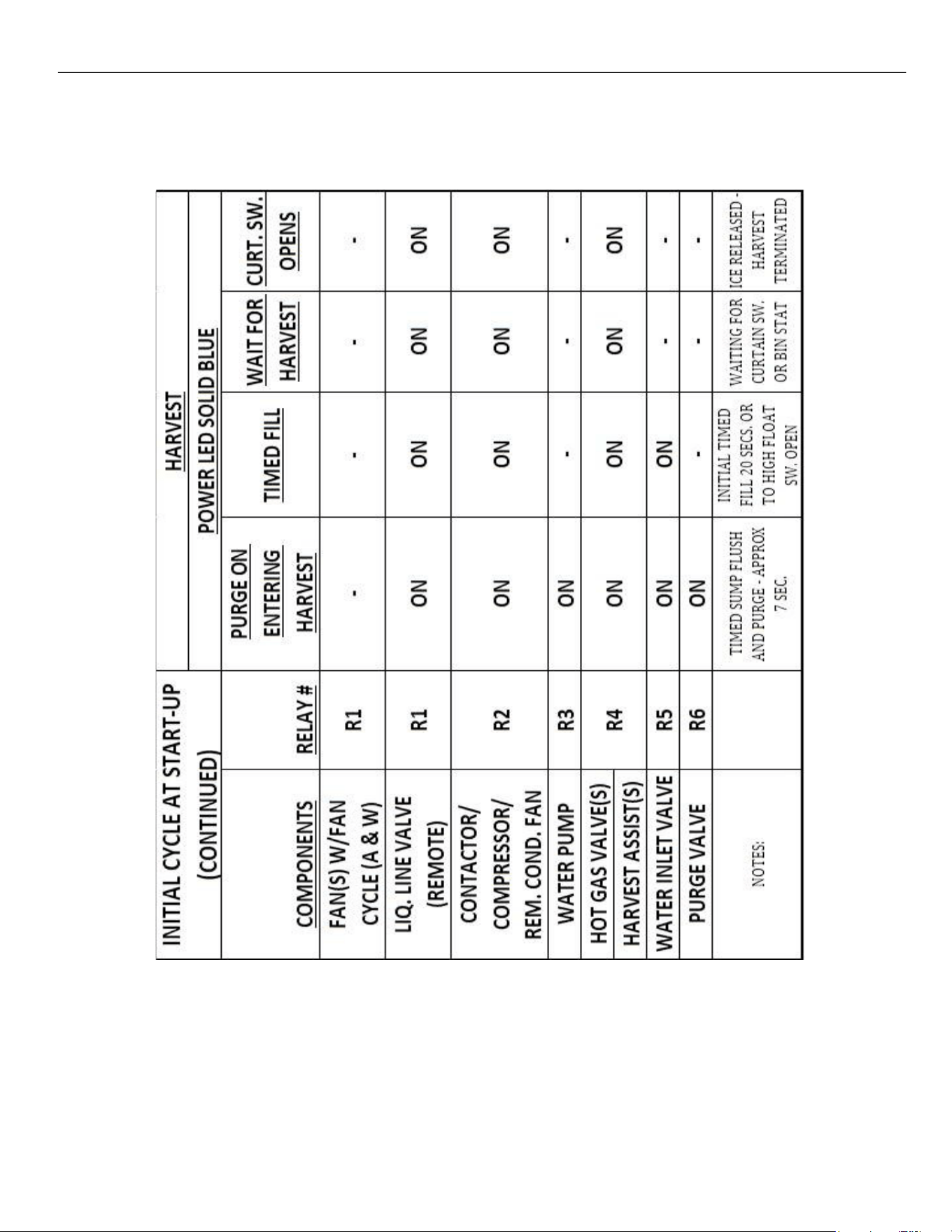
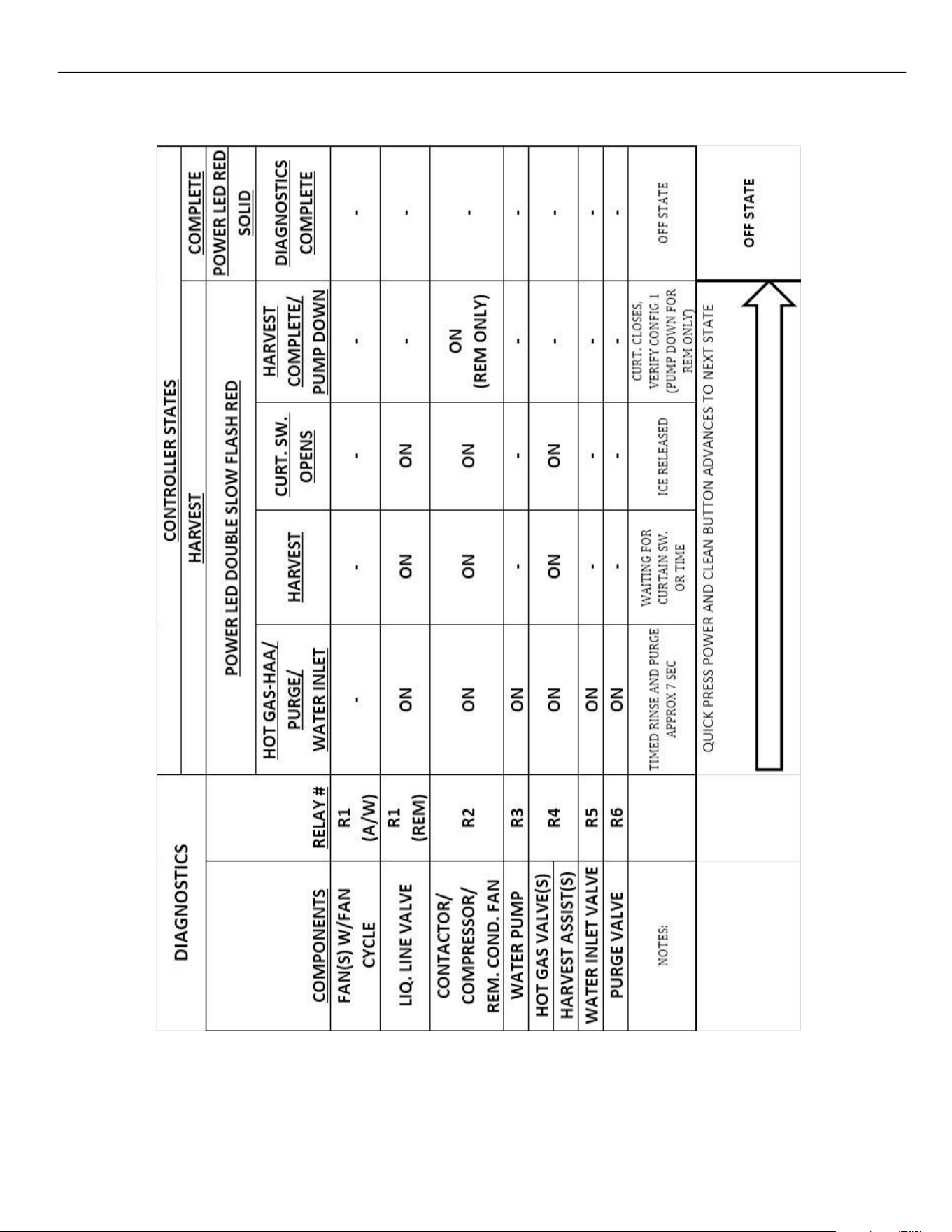
INITIAL HARVEST CYCLE AT START‐UP
ELEVATION SERIES CIM CUBERS
BOARD COMPONENT LED SEQUENCE
34
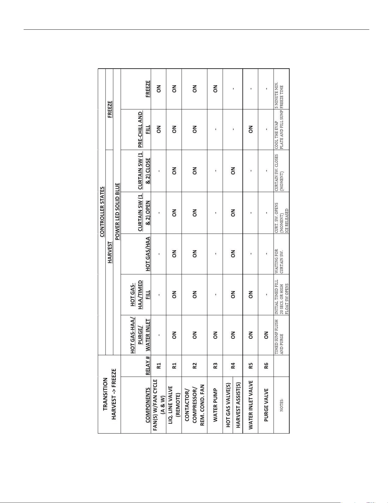
TRANSITION FROM HARVEST TO FREEZE
ELEVATION SERIES CIM CUBERS
BOARD COMPONENT LED SEQUENCE
35
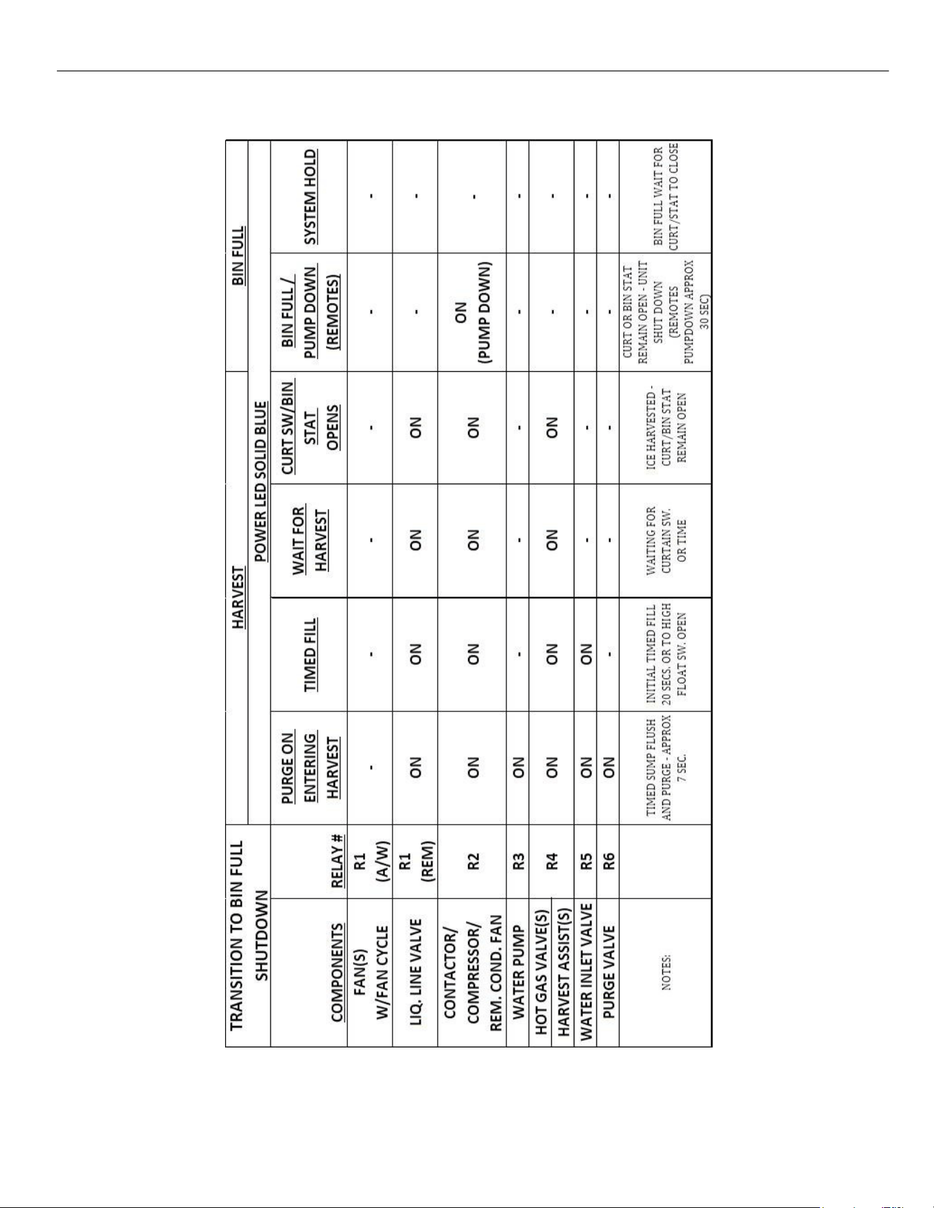
BIN FULL (CURTAIN OR STAT)
ELEVATION SERIES CIM CUBERS
BOARD COMPONENT LED SEQUENCE
36
DIAGNOSTICS IN FREEZE CYCLE
The Diagnostic sequence is started by pressing both the Power and Clean buttons for 6 seconds.
ELEVATION SERIES CIM CUBERS
BOARD COMPONENT LED SEQUENCE
37
DIAGNOSTICS IN HARVEST CYCLE
ELEVATION SERIES CIM CUBERS
BOARD COMPONENT LED SEQUENCE
38
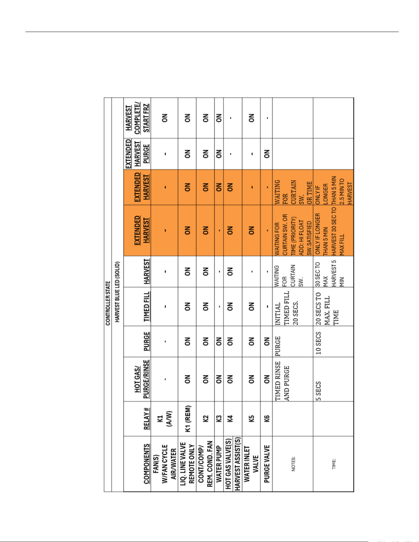
Board Led Sequence During Operation Test Control Boards from 2106 REV C1
INITIAL START‐UP THROUGH FREEZE CYCLE
CONTROLLER
STATE
FREEZE BLUE LED
(SOLID)
COMPONENTS
RELAY #
FILL
VERIFICATION
PRESSURE
EQUALIZE
PRESS. EQ.
W/ COMPR.
PUMP
DELAY
FREEZE
ANTI-SLUSH
2nd FILL
(units over
800lbs)
TIMED
FREEZE
FAN(S)
W/FAN CYCLE
K1
(A/W)
-
-
ON
ON
ON
ON
ON
-
CONT/COMP/
REM. COND. FAN
K2
-
-
ON
ON
ON
ON
ON
ON
WATER PUMP
K3
-
-
-
-
ON
-
ON
ON
HOT GAS VALVE(S)
K4
-
ON
ON
-
-
-
-
-
HARVEST ASSIST(S)
WATER INLET
VALVE
K5
ON
-
• - -
-
-
ON
-
PURGE VALVE
K6
-
-
-
-
-
-
-
-
NOTES:
Will Purge sump
if Hi float switch
is open to ensure
correct amount
of water in
trough.
IMPROVE
COMPRESSOR
START UP
IMPROVE
COMPR.
START UP
PRE-
CHILL
PLATE
MIN.
FREEZE
TIME (SP18
)
AT SUMP TEMP
38°F, TURN
OFF PUMP
LOW FLOAT
SW. WITH
DEBOUNCE
ABILITY TO
TURN OFF
FANS IF
NEEDED
TIME:
0 SECS TO MAX. FILL
TIME
5 SECS
5 SECS
30 SECS (
5 MIN OR MAX
FREEZE
20 SECS
APPROX. 5 MIN
INTO CYCLE
0 SECS
ELEVATION SERIES CIM CUBERS
BOARD COMPONENT LED SEQUENCE
39
TRANSITION FROM FREEZE INTO HARVEST
NOTE: Orange shaded area is for extended harvest on new control
40
ELEVATION SERIES CIM CUBERS
BUTTON FUNCTIONS
Button Functions
BUTTON FUNCTIONS
BUTTON PRESS
POWER
CLEAN
OFF
RED SOLID
QUICK
‐
FREEZE
3 SEC
‐
INDICATE CODE REVISION
‐
QUICK
CLEAN CYCLE
3 SEC
3 SEC
CLEAR ERROR CODES AND RESET COUNTERS (SINGLE
BLUE/YELLOW LIGHT FLASH WHEN RESET)
6 SEC
6 SEC
RUN DIAGNOSTICS PROGRAM
BIN FULL ON CURTAIN/
BIN STAT
BLUE SOLID
6 SEC
‐
MACHINE OFF
NORMAL OPERATION
FREEZE/HARVEST BLUE
SOLID
QUICK
‐
MANUAL HARVEST 1 ‐ FINISHES THEN SHUTS OFF
3 SEC
‐
MANUAL HARVEST 2 ‐ IMMEDIATE Harvest and shuts off
6 SEC
‐
MACHINE OFF
CLEAN IN PROCESS
RED SOLID/YELLOW SLOW
‐
QUICK
ADVANCE TO PURGE AFTER MIN. OF 5 MIN OF
6 SEC
CLEAN IN PROCESS
OFF - CLEAN IN PROCESS
RED SOLID/YELLOW SLOW
‐
QUICK
RETURN TO CLEAN IN PROCESS ‐ PURGE/RINSE
CLEAN COMPLETE
RED SOLID/YELLOW SOLID
‐
QUICK
Exit Clean complete MACHINE OFF
QUICK
‐
Exit Clean complete MACHINE OFF
ANY STATE
6 SEC
‐
MACHINE OFF
DIAGNOSTICS RED
DOUBLE SLOW
QUICK
QUICK
ADVANCE TO NEXT STATE
6 SEC
‐
MACHINE OFF
ERROR 1
RED QUICK
ERROR 3
RED & YELLOW QUICK
ERROR 4
DOUBLE RED & YELLOW
QUICK
ERROR 5
DOUBLE RED QUICK
ERROR 6
TRIPLE RED QUICK
ERROR 7
TRIPLE RED & YELLOW
3 SEC
3 SEC
3 SEC
Same as Below
3 SEC
3 SEC
CLEAR ERROR CODES AND RESET COUNTERS (SINGLE BLUE
/YELLOW LIGHT FLASH WHEN RESET)
Same as Above
RINSE
BLUE SLOW
QUICK
‐
ADVANCE TO FREEZE
HARVEST VERIFICATION
BLUE SLOW
QUICK
‐
NO ACTION
(CURTAIN SWITCH OPEN/CLOSE TO ADVANCE)
DEFAULT HARVEST
BLUE SLOW
QUICK
‐
NO ACTION
(CURTAIN SWITCH OPEN/CLOSE TO ADVANCE)
MANUAL HARVEST 1
DURING FREEZE OR HARV.
BLUE QUICK
QUICK
‐
RETURN TO NORMAL OPERATION BLUE
SOLID
MANUAL HARVEST 2
DURING HARVEST
BLUE QUICK
QUICK
‐
RETURN TO NORMAL OPERATION BLUE
SOLID
ELEVATION SERIES CIM CUBER
SUMP
41
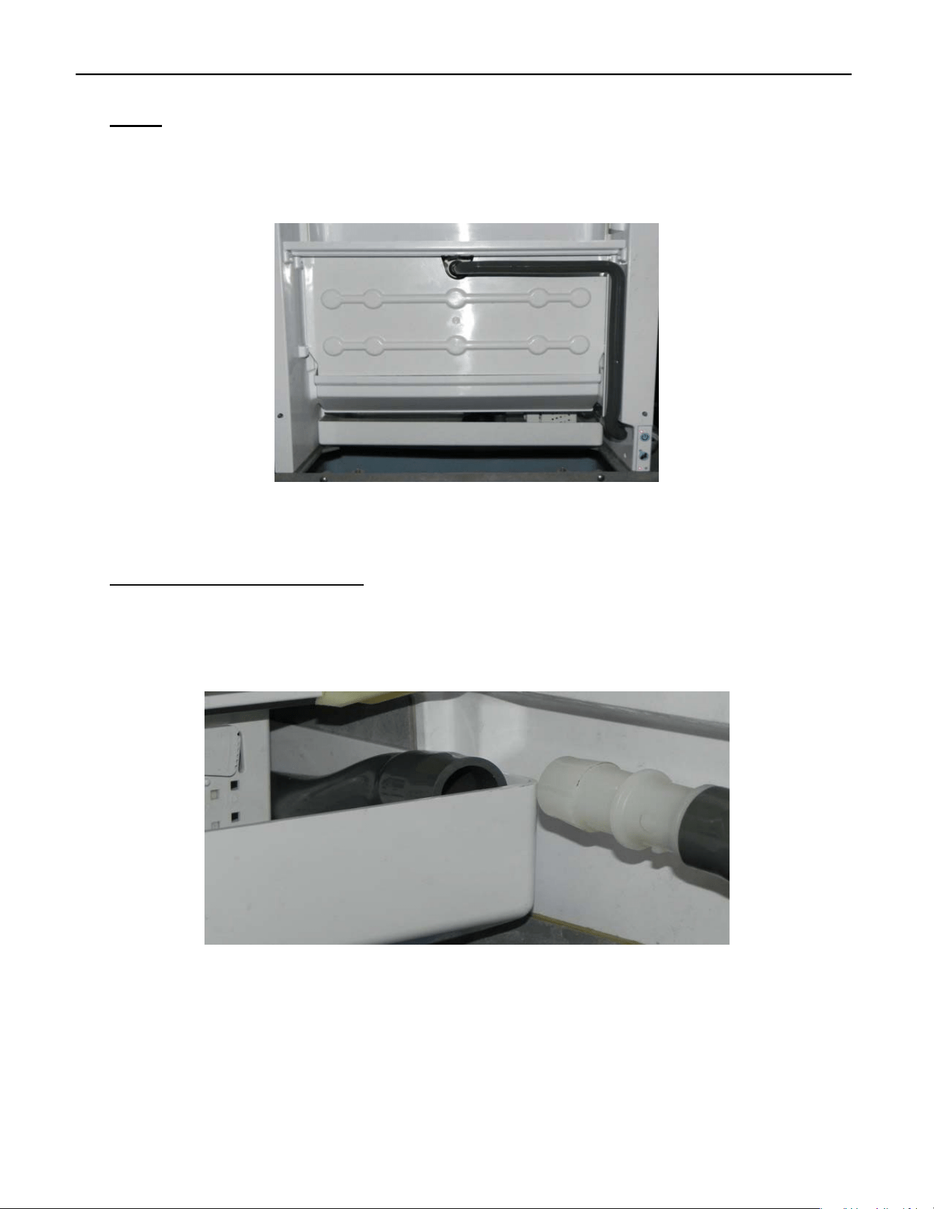
Sump
The Sump holds the potable water for the Freeze Cycle. It is located under the Evaporator and
accessible from the front of the unit. The Sump must be removed to access the Water Pump and
the Float Switch Housing.
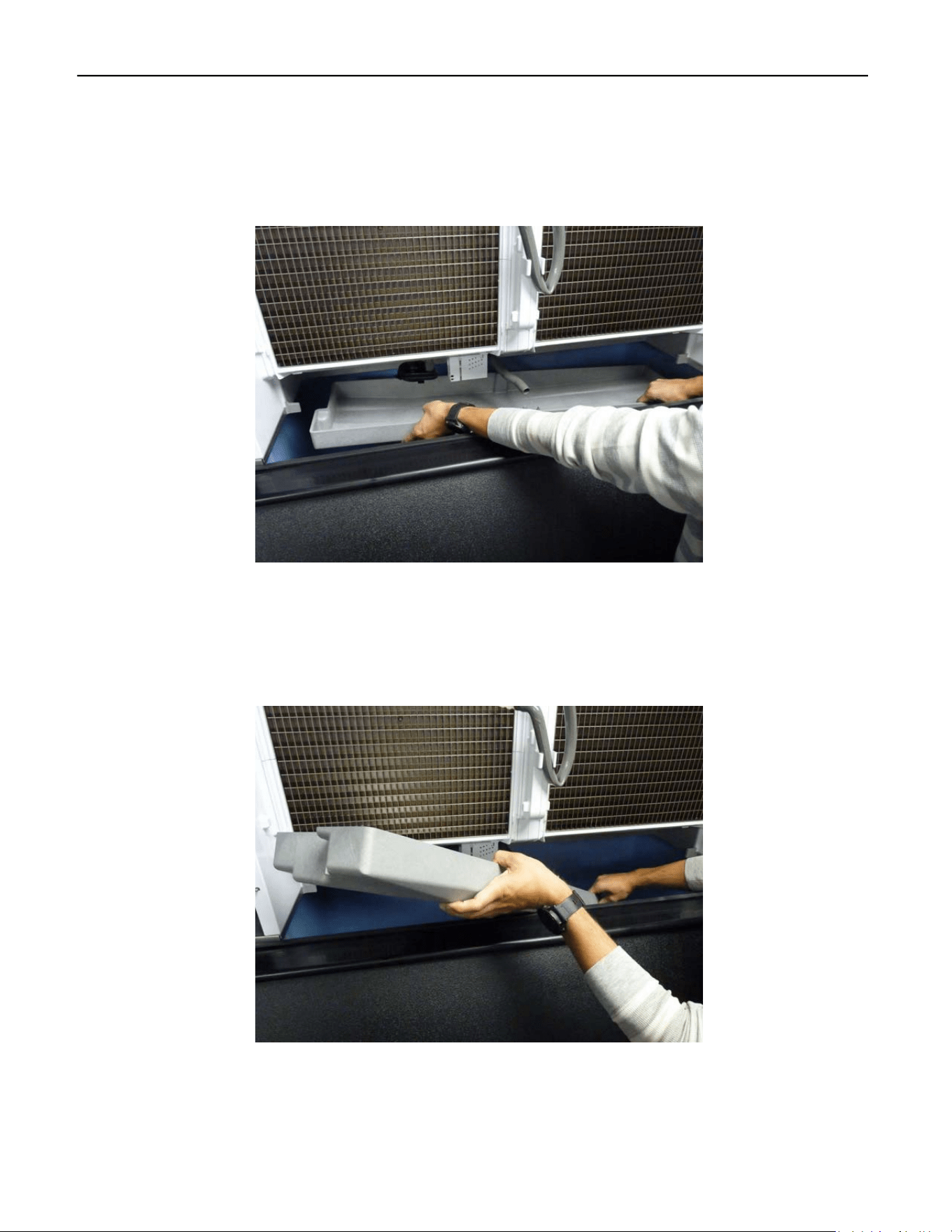
22” and 30 “ Units Sump Removal
First remove the Splash Curtain and Splash Guard.
Disconnect Water Pump Tube as shown above and tuck backside of tube into the Sump.
Splash Guard
Splash Curtain
SUMP
ELEVATION SERIES CIM CUBER
SUMP
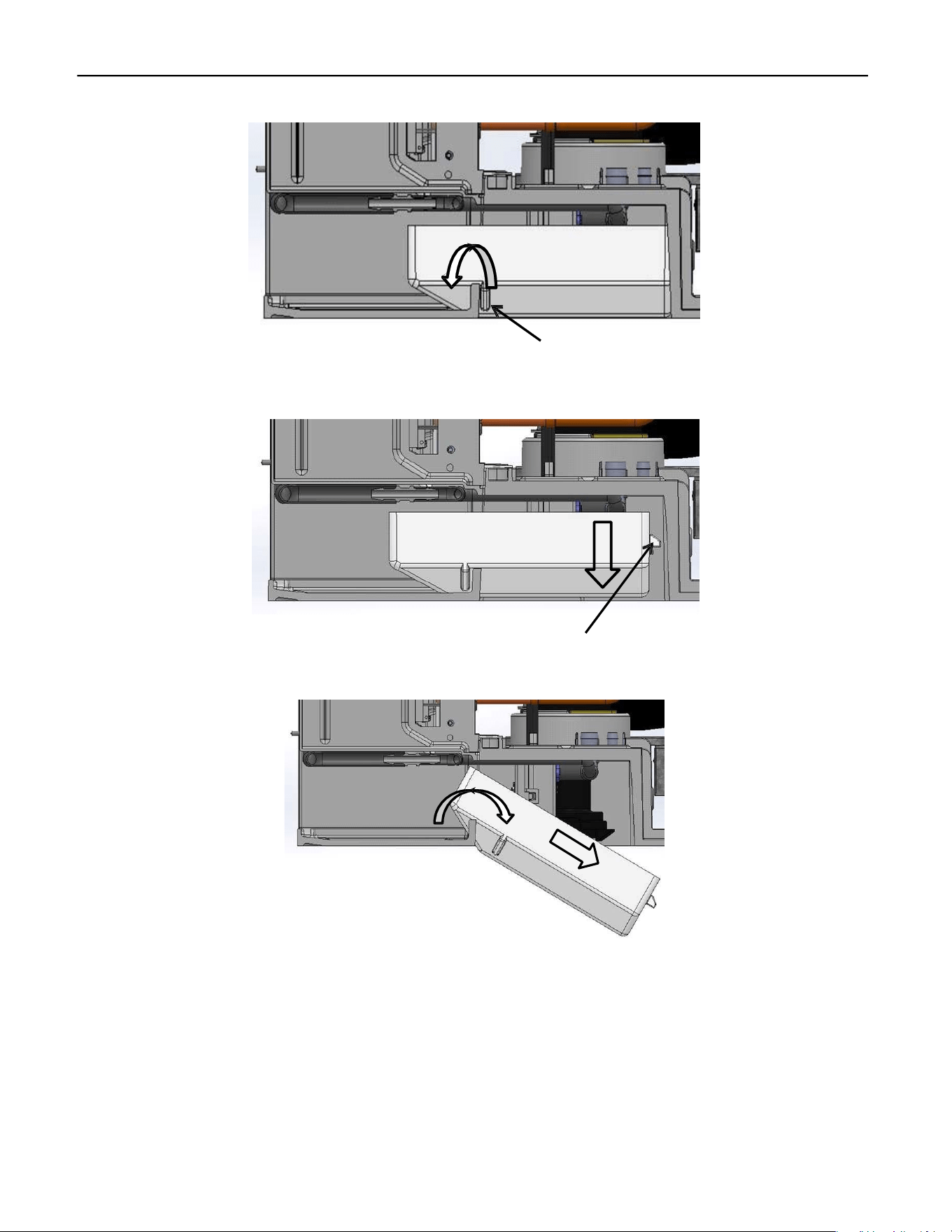
42
Lift the front of Sump and pull forward to clear the Sump Retainers from the frame.
With the Support Tabs now clear of the frame, allow the back of the Sump to fall clear of the
frame.
Again, lift the front of the Sump and push towards the back and down until Sump is clear of the
frame. Turn the Sump sideways and remove through the ice drop zone.
To reinstall, reverse process making sure to tuck Water Pump Tube into Sump as lift Sump into
place.
Sump Retainer
Support Tab
ELEVATION SERIES CIM CUBER
SUMP
43
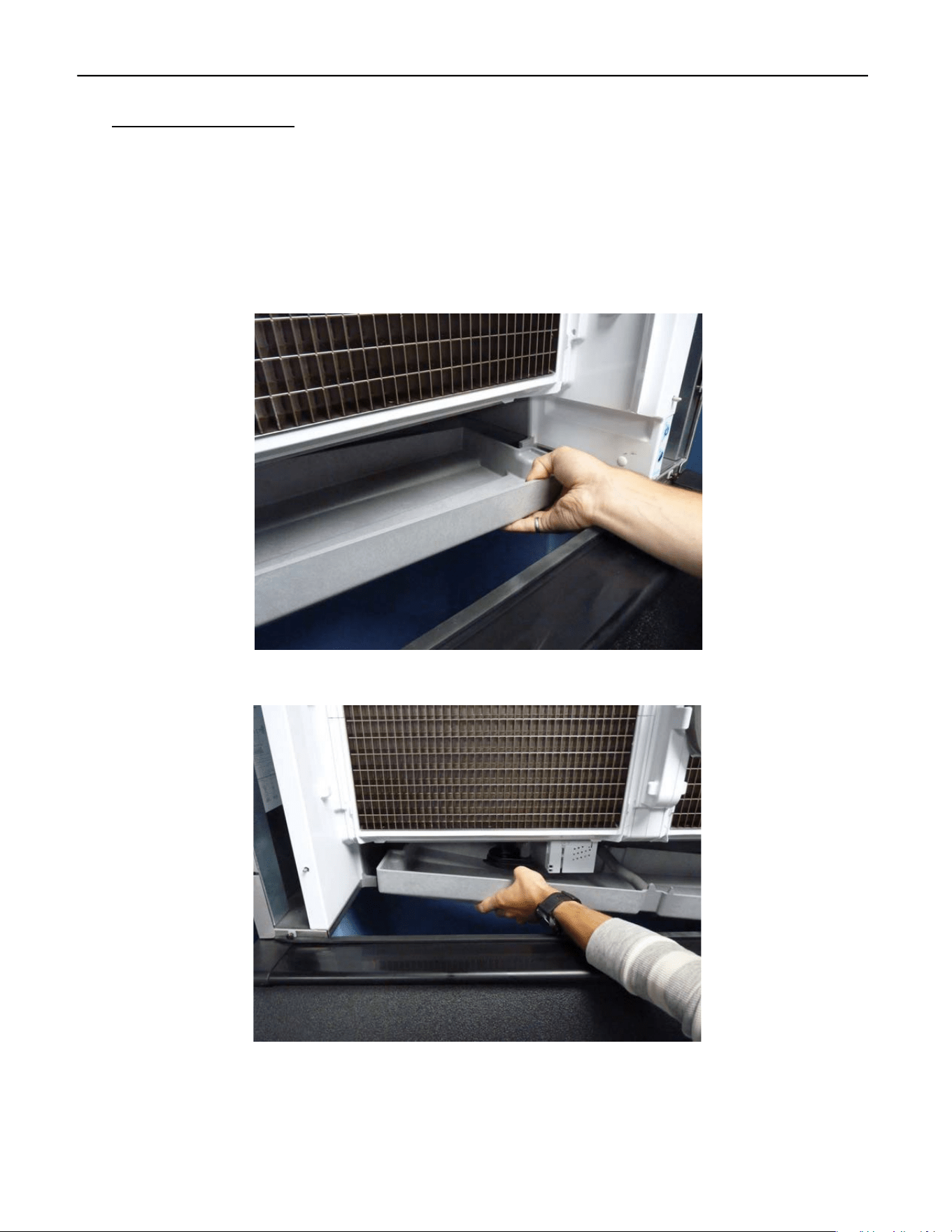
48” Unit Sump Removal
Removal of the splash curtain and splash guard is the same as the 22” and 30” units. You will do
this twice as there are two of each for the 48” units. The Water Pump Tube will need to be dis‐
connected also and this is the same process as in the 22” and 30” units as well. Tuck the backside
of the tube into the sump to keep it out of the way during sump removal.
Starting on the right side, lift up and pull forward to move the sump over the right‐side retention
feature.
Next, lower the right side of the sump into the bin and release the left side of the sump.
ELEVATION SERIES CIM CUBER
SUMP
44
After the sump is released from the retention features, lower the entire sump into the bin and
rotate it so it will come out the front of the unit.
Slowly remove the sump from the bin so as to not hit and damage other components.
Installation of the sump is the reverse of removal. To ease the installation using one hand under
the sump pan to lift on the back will help with the install. Ensure the left side is seated properly,
before attempting to press the right side into place. Improper placement of the left side can
lead to damage of the retention features during installation.
ELEVATION SERIES CIM CUBER
HIGH AND LOW FLOAT SWITCHES AND HOUSING
45
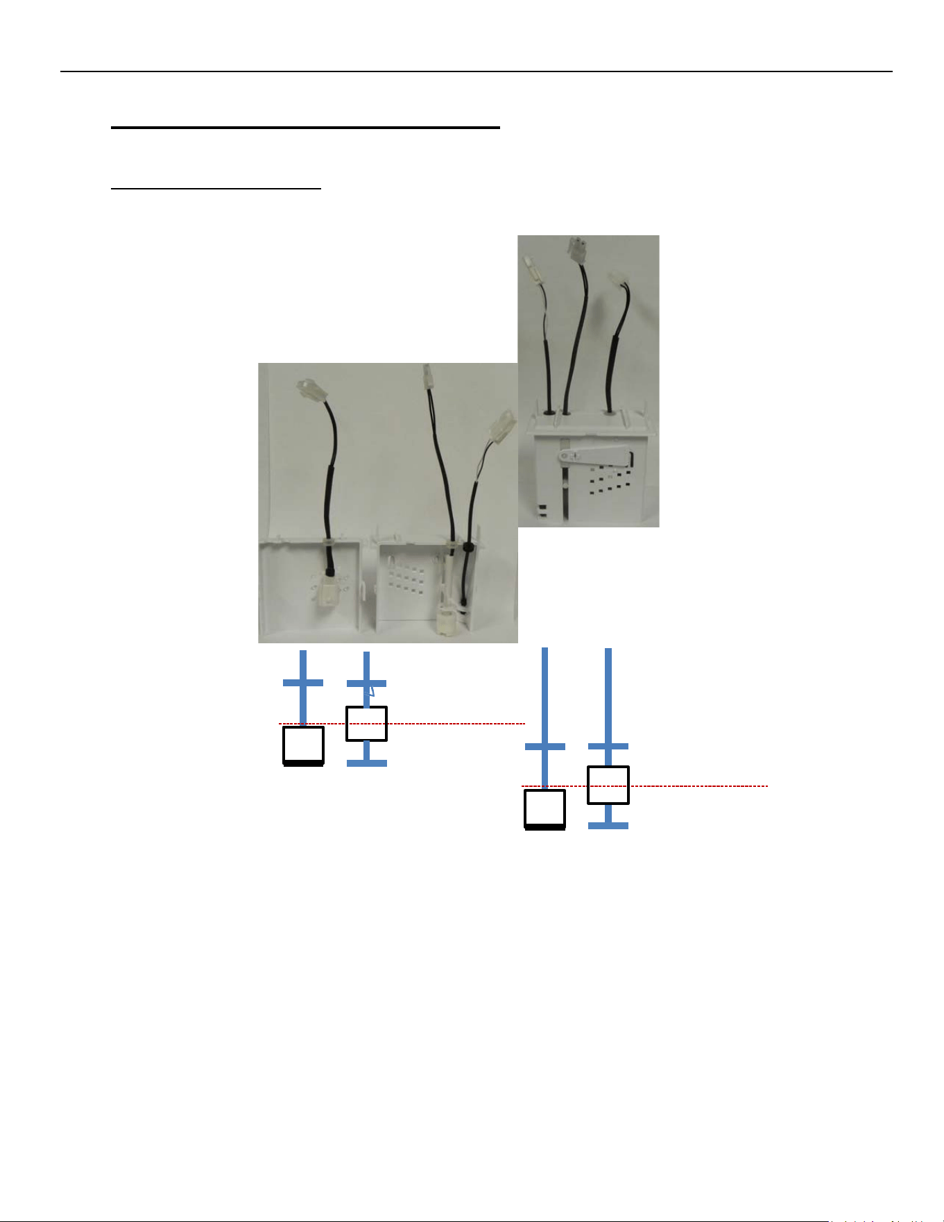
High and Low Float Switches and Housing
Float Housing Assembly
The Float Switch Housing Assembly contains the High and Low Float Switches along with the
Sump Thermistor. See below for the function of each. See also Sequence of Operation pg. 15.
High
Float
Low
Float
Thermistor
Switch Closed
Position
High Float
Switch opens Half
way up Stem.
Switch Closed
Position
Low Float
Switch Opens
halfway up Stem.
Switch Function
Switch Function
ELEVATION SERIES CIM CUBER
WATER PUMP
46
The High Float Switch is used to control the water level for ice making, cleaning and
sanitizing. The Float will rise with the water level, opening the contact of the switch and signal
the Board to close the Water Inlet Valve. The LED associated with the High Float switch will be
ON when the contacts of the switch are closed and will turn OFF when the contacts open. The
Low Float Switch is used to determine when the unit is ready to go into the Harvest Cycle during
ice pro‐ duction and when the Sump has been emptied of cleaner or sanitizer during the
Cleaning Cycle.
High and Low Float Switch Operation
The High Float Switch is used to control the water level for ice making, cleaning and
sanitizing. The Float will rise with the water level, opening the contact of the switch and signal
the Board to close the Water Inlet Valve. The LED associated with the High Float switch will be
ON when the contacts of the switch are closed and will turn OFF when the contacts open. The
Low Float Switch is used to determine when the unit is ready to go into the Harvest Cycle during
ice pro‐ duction and when the Sump has been emptied of cleaner or sanitizer during the
Cleaning Cycle
The LED associated with the Low Float Switch operates the same as the LED for the High Float
Switch. The LED will ILLUMINATE when the contact of the float is closed and will turn OFF when
the contacts are open. The Thermistor monitors the water temperature in the Sump during the
Freeze Cycle. At 38°F the system initiates an “Anti‐slush” shutdown of the Water Pump for 20
seconds when the water temperature reaches 38°F to decrease the risk of slushing in the Sump.
Additionally, the system will perform an anti‐slush shutdown of the Water Pump whenever the
water temperature reaches 28°F.
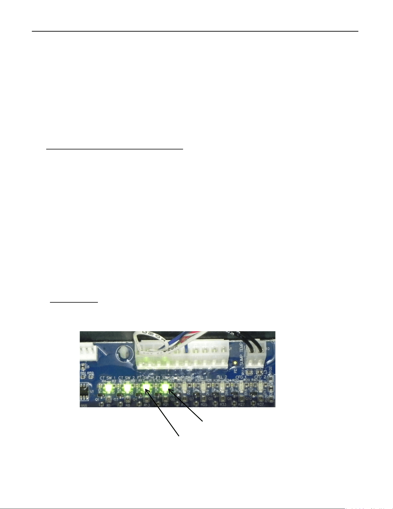
Troubleshooting
When the High and Low Floats are in the down position, the contacts for the switches are
closed and the LEDs on the Board should be illuminated.
Low Float Switch LED
High Float Switch LED
ELEVATION SERIES CIM CUBER
WATER PUMP
47
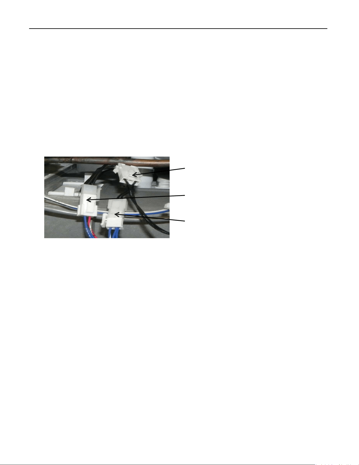
As the water level rises, the floats rise with it and the contacts of the switches will open
and the LEDs on the Board will go OFF. This can be verified by removing the Sump and checking
first the LEDs on the Board. Without the presence of water, both floats should be in the down
position and the LEDs on the Board should be illuminated. If one or both LEDs are OFF,
disconnect the Float Switches at the connectors along with the Thermistor and remove the
Float Housing by gently pulling down on it from the ice drop zone.
Thermistor Connector
High Float Switch Connector
Low Float Switch Connector
Open the housing and examine each float for movement of the float and cleanliness. With a
meter set on continuity, verify the contacts on the float open and close with movement of the
float. If float is clean and contacts do not change with float movement, replace Float Switch
Housing Assembly. If one or both of the LEDs remain OFF with Float Switches that are known to
be good, the Board or Wiring Harness may be the issue. Keep in mind: sometimes the LEDs will
be on even if the unit isn’t working. If there’s resistance in the switch, a small amount of voltage
might pass through—just not enough for the control to operate.
ELEVATION SERIES CIM CUBER
WATER PUMP
48
The Bridge Thickness on units under 400# production should be 3/16” while units over 400# pro‐
duction should be 1/8” thick when measured across the middle of the plate. Minor Adjustments
can be made to the bridge thickness by moving the Water Level Adjustment Arm of the Float
Housing up for a thicker bridge or down for a thinner bridge. This adjustment can be made at
any time during the freeze or defrost cycle and the results verified on the following cycle.
Recommended Float Setting Chart.
To make this adjustment the water trough, Splash guard, and lower water curtain will need to be
removed. Pull gently down on the float, the float will come out through the bottom of the machine and this
setting can then be made.
Splash Curtain
Thicker
Bridge
Sump
Thinner
Bridge
ELEVATION SERIES CIM CUBER
WATER PUMP
49
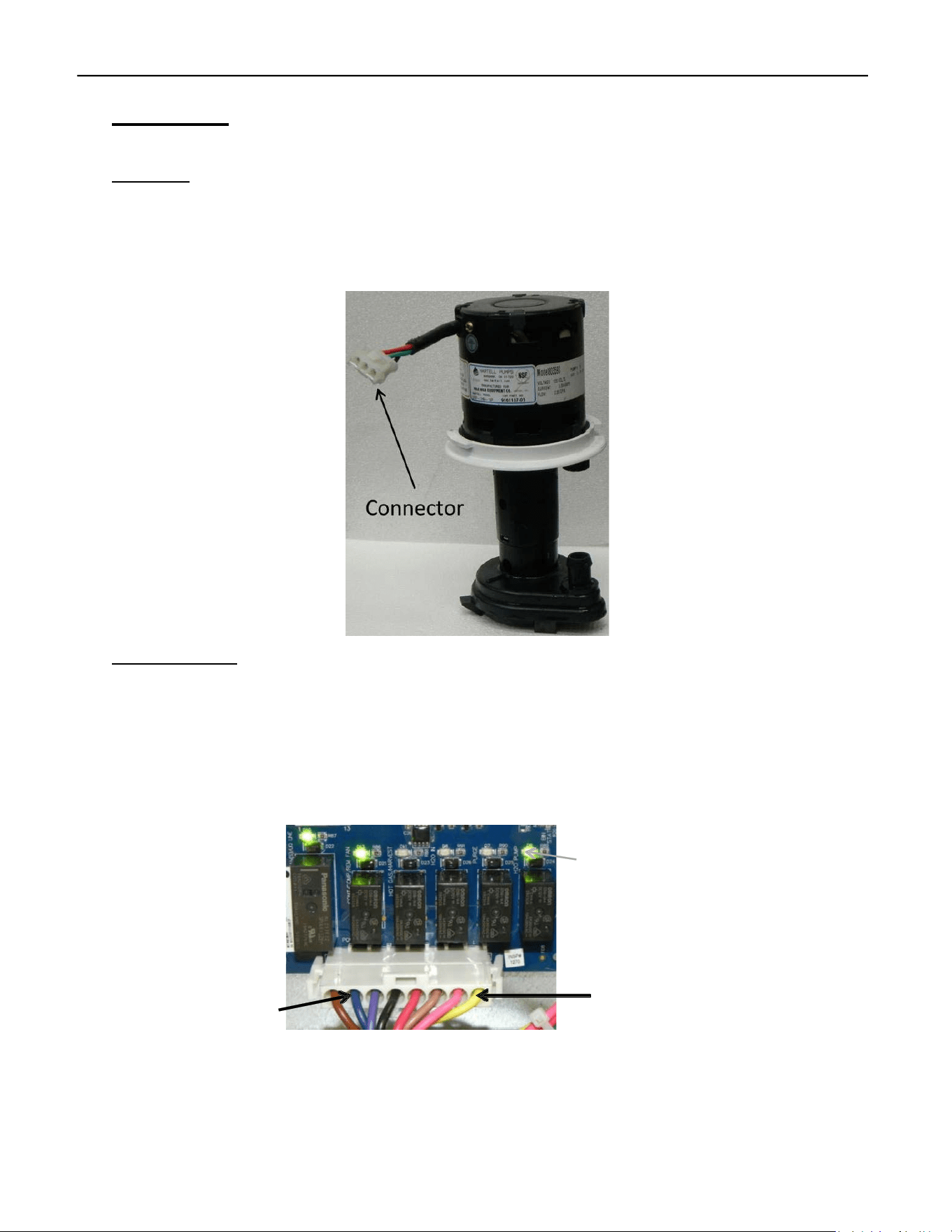
Water Pump
Operation
Relay 6 (LED ON) powers the Water Pump after a 30‐second evaporator pre‐chill during the Freeze
Cycle. At the start of the Freeze Cycle following shutdown (OFF or Bin Full), the Water Pump pauses for
20 seconds to prevent sump slushing before running normally. The pump operates continuously during
the Cleaning Cycle once the Sump is filled.
Troubleshooting
If Relay 6 LED is ON but the Water Pump does not run, verify line voltage between the Yellow
and Blue wires on the Molex. If line voltage isn’t found, verify connection of Molex to Board and
reverify. If no voltage is found, the issue is the Board. If line voltage is found, verify line voltage
at Water Pump connector. If no voltage is found, the issue is the wiring or connectors. If line
Voltage is found, but the Water Pump won’t spin, the issue is the Water Pump. Clean or replace
as required.
When verifying voltage out of Board, check at the Blue and Yellow wires.
Relay 6 Water
Pump LED
R1 R2
R3
R4
R5
R6
L2/N
Water
Pump
Voltage can also be checked at the connector at the Water Pump.
ELEVATION SERIES CIM CUBER
WATER DISTRIBUTION TUBE
50
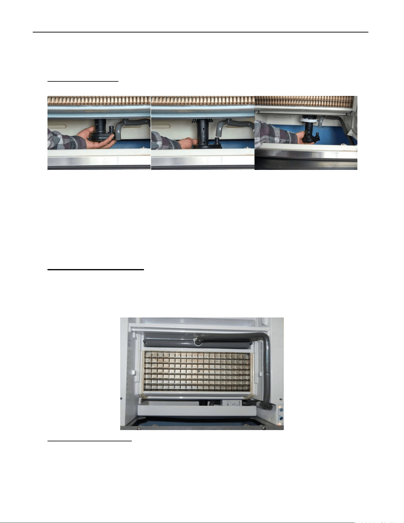
Water Pump Removal
The “foot” of the Water Pump points towards the right front corner of the unit. Grasp the foot
and turn counterclockwise. When the foot points towards the right rear corner, you will feel the
weight of the pump as the collar clears the base connections. Lower the Water Pump and dis‐
connect. Reinstall the Water Pump by first making the electrical connection, the push Pump up
pointing the Foot at the right rear corner and turn clockwise to secure.
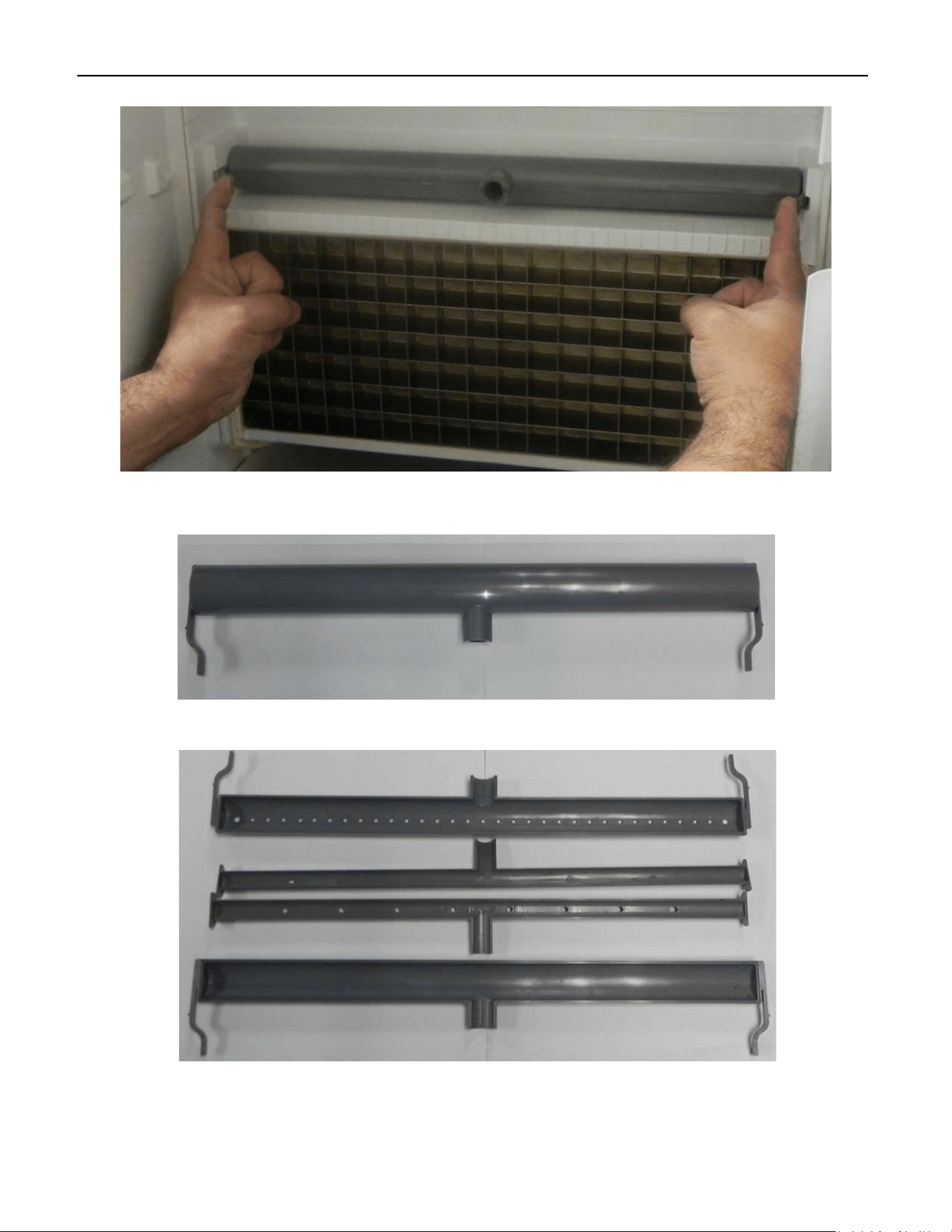
Water Distribution Tube
The Water Distribution Tube has an inner tube and an outer tube. The water enters through the
inner tube and sprays the water up into the outer tube relieving the pressure on the water.
Gravity takes over and the water runs out the outer tube holes pointed down. The water runs
smoothly and evenly over the Evaporator.
Removal and Disassembly
Disconnect Water Pump Tube from Water Distribution Tube.
ELEVATION SERIES CIM CUBER
WATER DISTRIBUTION TUBE
51
Gently squeeze the tabs inward on the Water Distribution Tube and forward towards the front
of the unit.
The Water Distribution Tube comes apart easily. It should be taken apart and cleaned regularly
along with the rest of the unit. The pieces are Poka‐yoke, meaning it only goes back together one
way.
ELEVATION SERIES CIM CUBER
WATER INLET VALVE
52
R1
R2 R3
R4
R5
R6
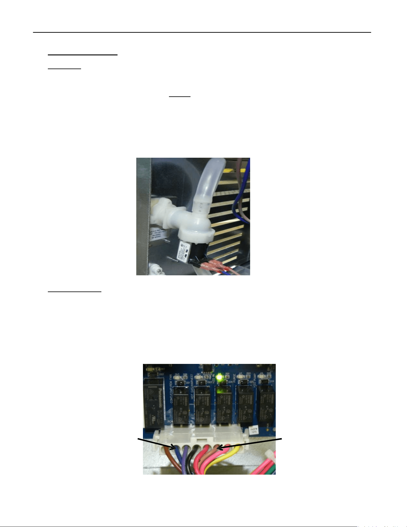
Water Inlet Valve
Operation
Relay 4 on the Board (LED ON) energizes the Valve first on initial startup to fill the Sump until
the contacts of the High Float Switch open, indicating a proper amount of water for ice making.
The purpose is to verify water supply before starting the unit. After the initial cycle is complete,
the Valve will be energized during the Harvest Cycle and if needed, energized during the Pre‐
Chill to complete filling the Sump (See Sequence of Operation pg. 9). In either case, Relay 4 will
be illuminated when the Water Inlet Valve is energized. During the Cleaning and Sanitizing Cycle
the Water Inlet Valve will be energized several times during the rinse and purge portion of the
cycle (see Cleaning Instructions pg. 56).
Troubleshooting
The High Float Switch contacts must open within 5 minutes. If Relay 4 is on but the Water Inlet Valve
doesn’t open, first check the water supply. Then check for line voltage between the (tan and blue)
Molex wires. If absent, the Board is faulty; if present, check voltage at the Water Inlet Valve coil. No
voltage means faulty wiring or connectors. If voltage is present, test coil resistance—no resistance
indicates an open coil, so replace the valve. If the coil is fine, inspect and clean or replace the Water
Inlet Valve as needed, and check incoming water supply and filters for blockages.
L2/N L1
Voltage can also be verified at the connector at the coil of the Water Inlet Valve.
ELEVATION SERIES CIM CUBER
PURGE VALVE
53
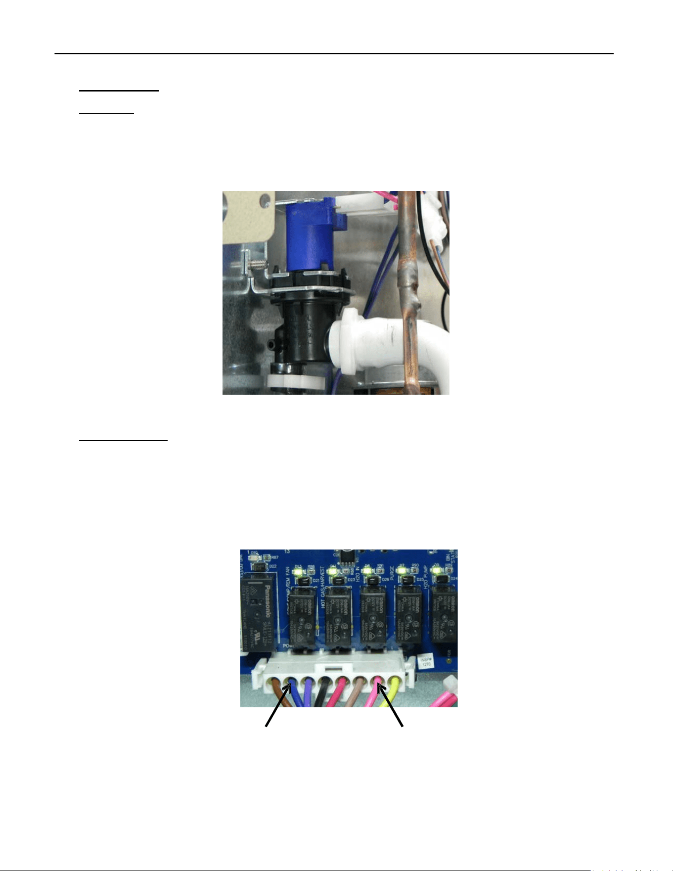
Purge Valve
Operation
The Purge Valve is located on the back of the Evaporator. The Valve should open when energized
by Relay 5 on the Board (LED ON) during the Harvest Cycle to help empty the mineral laden
water (see Sequence of Operation pg. 9) and during the Cleaning/Sanitizing Cycle (see Cleaning
Instructions pg. 56).
Troubleshooting
The Purge Valve, located behind the Evaporator, opens when Relay 5 (LED ON) is energized during the
Harvest and Cleaning/Sanitizing Cycles to remove mineral‐rich water. If the valve does not open when
Relay 5's LED is lit, unplug the coil connector and check for line voltage. If there is none, check the
output at the board's Molex (pink and blue wires). No voltage means the board is faulty; if voltage is
present, the issue is with the wiring between the Molex and the valve connector.
Voltage can also be verified at the connector at the coil on the Purge Valve.
R1
R2 R3
R4
R5
R6
L2/N
L1
ELEVATION SERIES CIM CUBER
HARVEST ASSIST ASSEMBLY/HOT GAS VALVE
54
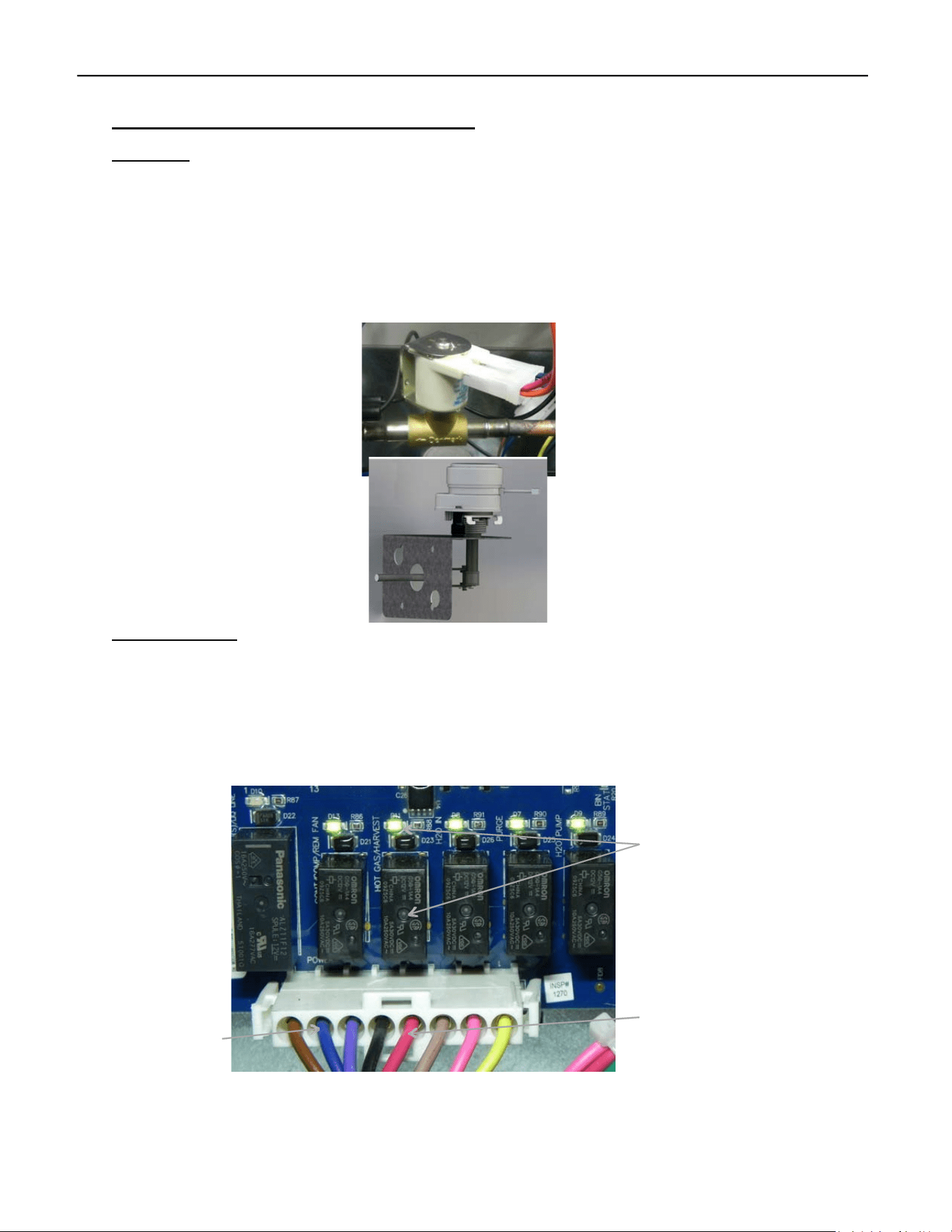
Harvest Assist Assembly/Hot Gas Valve
Operation
The Harvest Assist Assembly is mounted to the back of the Evaporator Assembly. It is energized
by Relay 3 along with the Hot Gas Valve. As the unit enters the Harvest Cycle, Relay 3 will
illuminate indicating voltage is being sent to the Harvest Assist Assembly and the probe will be
pushed forward to meet the ice slab. As the Evaporator warms, the Probe on the Harvest Assist
will move forward to help release the ice from the plate. As the ice slab falls it will open the
Magnetic Curtain Switch contacts. Relay 3 will then be de‐energized, and the Harvest Assist will
automatically return to the starting position.
Troubleshooting
The Harvest Assist Assembly is powered by the Hot Gas Valve via Relay 3 during Defrost. To test, enter
Diagnostics by holding Power and Wash for 6 seconds, then quickly press both Power and Clean to
start Harvest (R2‐R6 LEDs should light up). Ensure Relay 3’s LED is on and check voltage between Blue
and Red at Molex. No voltage suggests a problem with the Board or Molex. If voltage is present, check
at the Harvest Assist connector. If voltage exists but the probe doesn't advance, the Harvest Assist is
faulty.
R3 Hot Gas/Harvest
Assist LED
L2/N
Hot Gas/Harvest
Assist
ELEVATION SERIES CIM CUBER
MAGNETIC CURTAIN SWITCH
55
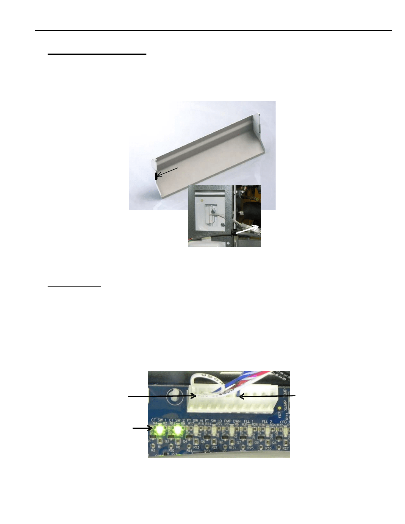
Magnetic Curtain Switch
The Magnetic Curtain Switch is a proximity switch that closes the contacts when the Splash
Curtain closes. LEDs on the Board indicate a closed switch when illuminated.
Note: In 48” units there is a curtain magnet and proximity switch for both plates, on the left and
right sides of the unit.
Troubleshooting
Should the LEDs on the Board be off when the Splash Curtain is closed, first verify the magnet is
in place on the Splash Curtain and the Wiring Harness is properly connected at the Switch and at
the Board. If all is verified, use a different magnet against the switch. If it still will not close,
replace the Magnetic Curtain Switch. Keep in mind: sometimes the LEDs will be on even if the
unit isn’t working. if there’s resistance in the switch, a small amount of voltage might pass
through—just not enough for the control to operate.
12v Curtain Switch 12v Common
Curtain Switch LED’s
Magnet
Connector
ELEVATION SERIES CIM CUBER
FAN MOTOR
56
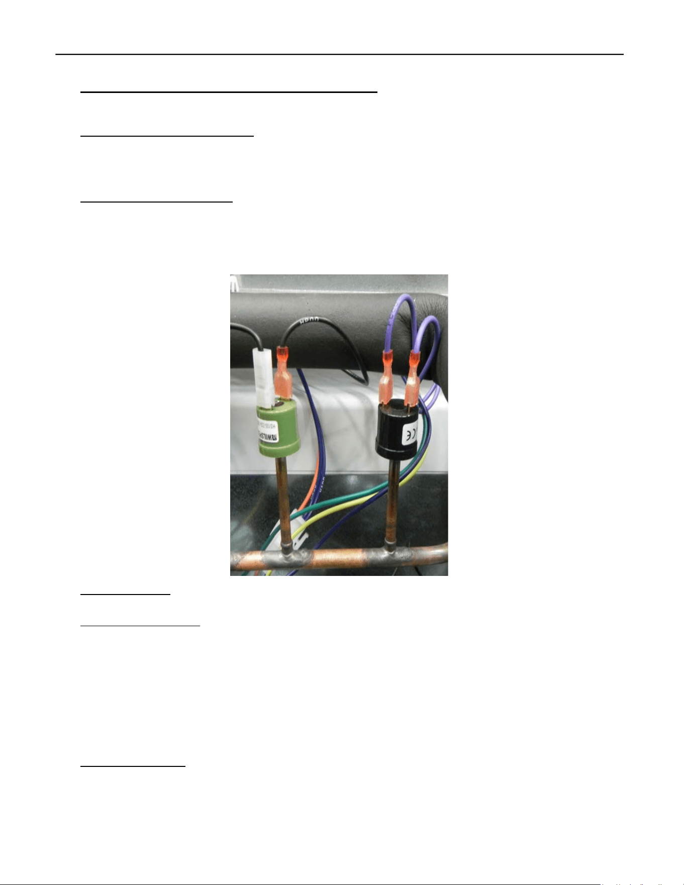
High Pressure Cut-out and Fan Cycle Switch
High Pressure Cut-out (left)
The High‐Pressure Cut‐out is set to open at 450 psig (r‐404, and R‐449a models), 350 on r‐290
models and de‐energizes the Contactor as a safety on the unit.
Fan Cycle Control (right)
The Fan Cycle Control helps maintain head pressure in cooler ambient temps. The control closes
at 250 psig, energizing the Fan Motor and opens at 190 psig. The fan control is not needed in
normal operating conditions and should only be placed in circuit if the temps drop below 60° F
(15.5°C)
Troubleshooting
High Pressure Cut-out
The High‐Pressure Cut‐out opens at 450 psig to de‐energize the Contactor and shutdown the
Compressor. The control recloses at 350 psig. Should the control open during the Freeze Cycle,
the unit may go into Error 1 state, indicating the Freeze Cycle has run for more than 1 hour. To
quickly check the unit operating pressure, run a Diagnostic Cycle with stub gauges on the unit.
A dirty or blocked Condenser, failed Fan Cycle Control, failed Fan Motor, high side restriction or
refrigerant over charge can be the cause. Note R-290 Models will have a 350psi open and a
250 psi close.
Fan Cycling Control
The Fan Cycle Control is designed to close at 250 psig and open at 190 psig, helping regulate head
pressure when conditions are cool. If the control activates at pressures outside this range, it should
be replaced. R‐290 units do not include a fan cycle control. NOTE: R-290 units will not have a fan
cycling control.
ELEVATION SERIES CIM CUBER
FAN MOTOR
57
Relay 1LED
R1
R2
R3
R4
R5
R6
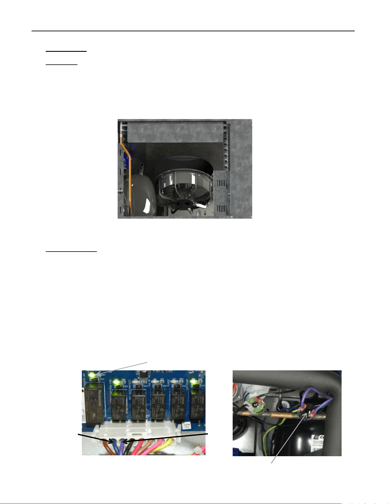
Fan Motor
Operation
The Fan Motor (Self‐Contained Air‐Cooled Units) is Mounted to the Fan Shroud covering the Con‐
denser at the rear of the unit. It is energized by Relay 1 and controlled by the Fan Cycling Switch.
The Switch should close at 250 psi of head pressure and power the Motor. The Fan Cycle Switch
(if equipped) should open at 190 psi of head pressure, and the Fan Motor will de‐energize.
Troubleshooting
When the Fan Motor is inoperable or cycling outside of the operational parameters, first verify
the LED for Relay 1 is illuminated, indicating the Board is calling for the Fan Motor to run. If the
unit is in the Freeze Cycle and the LED is not illuminated, the issue may be the board. If it is
Illuminated, check voltage between the Violet and Blue with a meter. Line voltage should be
shown. If inappropriate voltage is shown, verify the Molex connection at the Board and correct
if loose. If there is still no voltage out, replace the Board. If voltage is verified, check contacts of
Fan Cycle Switch for voltage then check contacts which should be closed at pressures above 250
psi. If open in these conditions, jump control. If Fan Motor comes on, issue is Fan Cycling
Control. If the Motor does not come on, check the connection at Motor. If verified, the issue is
the Fan Motor.
L2/N
Fan
Fan Cycle Control
ELEVATION SERIES CIM CUBER
EVAPORATOR
58
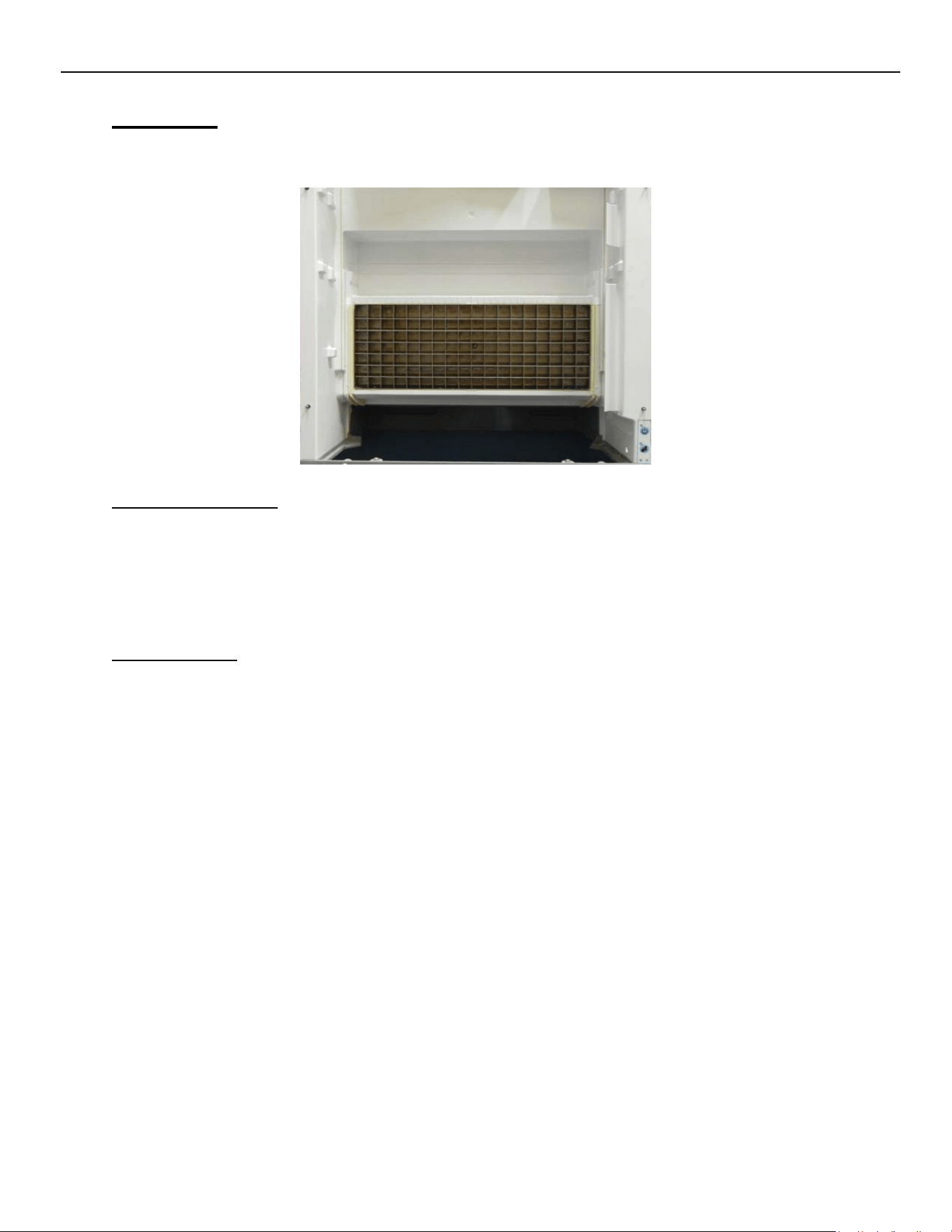
Evaporator
The nickel‐plated Evaporator Assembly has a copper core to assure good heat transfer. Water is
pumped gently over the Evaporator during the freeze cycle for even ice formation.
Evaporator Operation
The Evaporator should be fully flooded with refrigerant for most of the freeze cycle to ensure
even ice formation. The serpentine on the back of the Evaporator starts at the bottom right
corner of the plate (viewed from the front). The refrigerant lines run horizontally back and forth
to the middle of the plate then rise along the left‐hand side to the top. The line continues to
“serpentine” downward to the middle of the plate and exit the Evaporator.
Troubleshooting
The Evaporator should always have a nickel appearance. Should the Evaporator have a “rust”
color after a thorough cleaning, the plating may have come off and a replacement may be
required. A dull “rainbow shimmer” may indicate an improper cleaner was used on the unit.
Only approved Nickel Safe ice machine cleaner should be used.
An improper ice formation can be caused by a water or refrigeration issue.
A dirty water system can cause poor water flow over the Evaporator resulting in improper ice
formation. See pg. 56 for Cleaning Instructions.
A refrigeration issue such as a low charge or restricted TXV could show on the Evaporator as ice
forming on the bottom of the plate with thin to no ice forming on the top half. Verify refrigerant
pressures on the Technical Specifications chart on pg. 60.
Should the ice slab resist coming off the plate, examine the Evaporator for loss of plating,
pitting, mineral accumulation and/or loose horizontal dividers. Should any of the horizontal
dividers separate from the base, replacement of the Evaporator is recommended.
ELEVATION SERIES CIM CUBER
EVAPORATOR
59
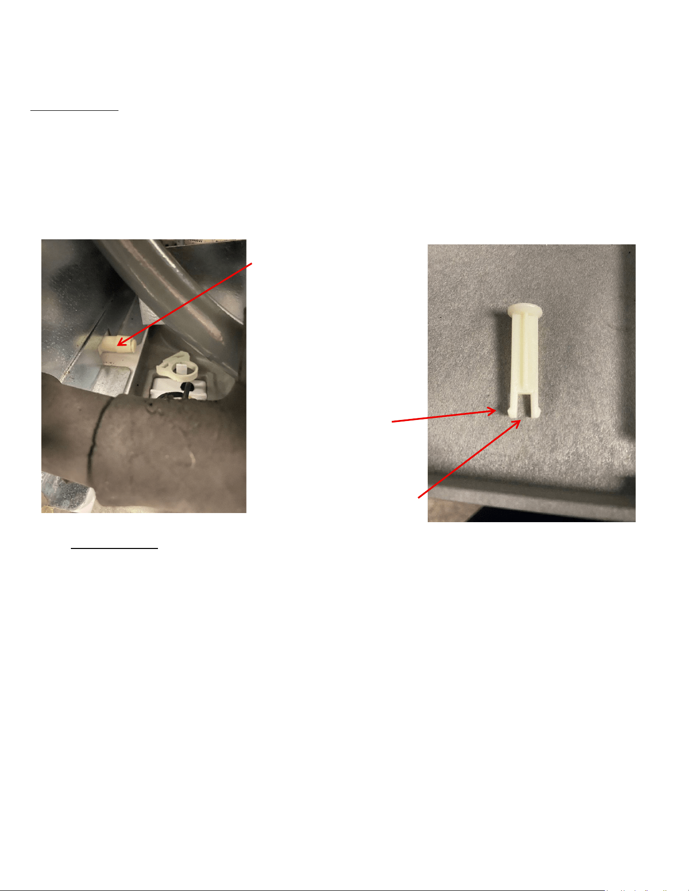
Evaporator Drain
Located below the purge valve, a 3/8” diameter spout with a pop‐it valve is installed on the back of the
evaporator, connecting to the drain line. This design prevents water from flowing back into the evaporator
during purging.
Drain Spout
Ears
Pop-It Valve
Troubleshooting
Remove the hose clamp and drain tube from the barbed spout. Verify that the pop‐it is fully closing; if it is not,
remove the pop‐it and ensure the ears are positioned horizontally within the tube. Additionally, confirm that
the spout is free from any obstructions.
ELEVATION SERIES CIM CUBERS
EVAPORATOR REPLACEMENT
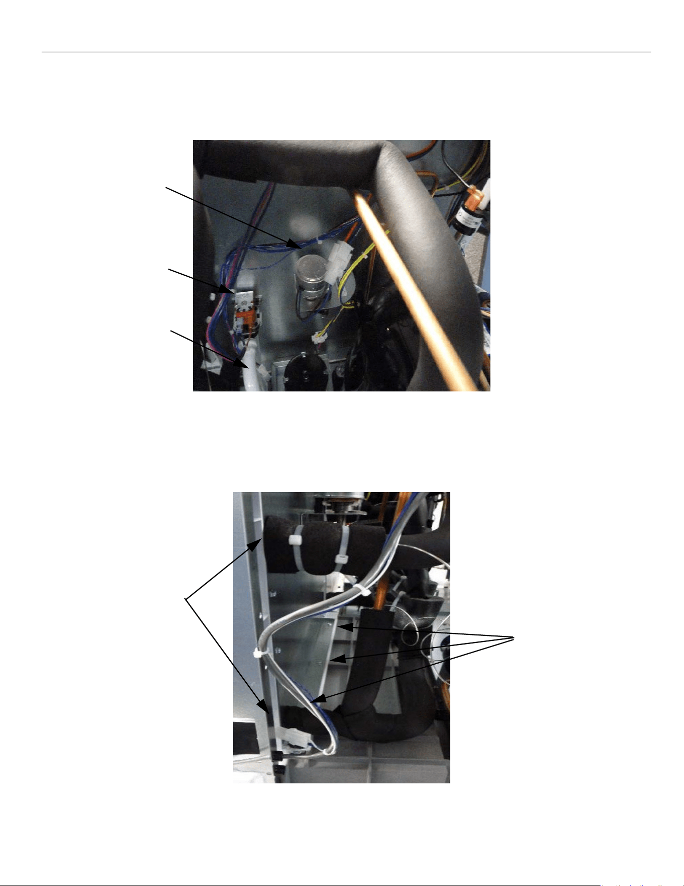
60
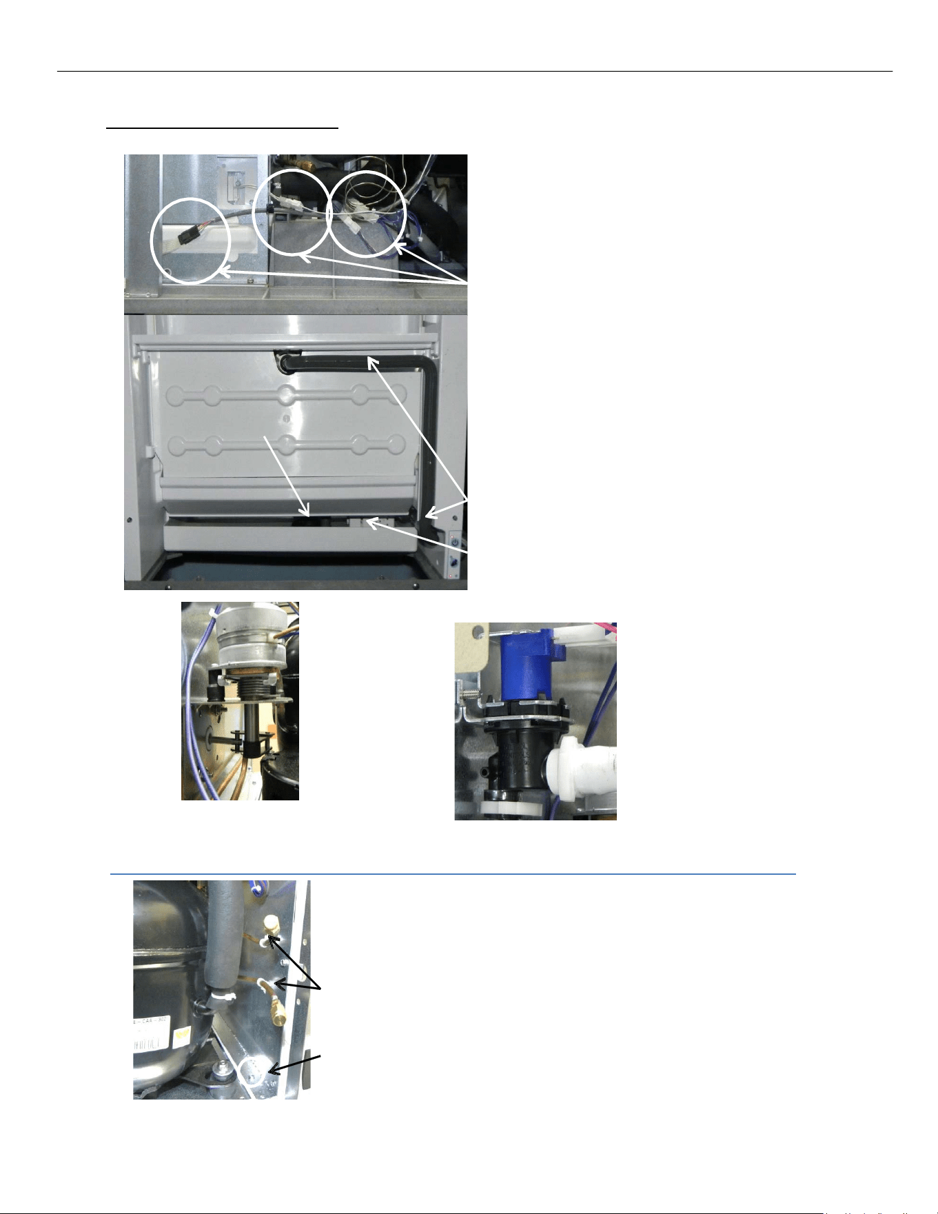
Single Evaporator Plate Units
While recovering the refrigerant from the unit,
disconnect High and Low Float Switches,
Thermistor, Curtain Switch and Push Pad ribbon and
move the wiring clear of the area.
Connectors
Remove the Splash Curtain, Evaporator Cover, Top
Evaporator Cover, Water Distribution Tube,
Water Pump Tube and its connector, Sump, Water
Pump, and Float Switch Housing Assembly.
Water Pump Tube & Connector
Float Switch Housing
Harvest Assist
Assembly
Purge Valve
On the rear of the Evaporator Assembly, disconnect Harvest Assist Assembly, Purge Valve and
Purge Tube and remove from unit.
Cut Zip Ties
Remove 1/4” screws
Evaporator Top
Evaporator Cover
Water Pump
Splash Curtain
Sump
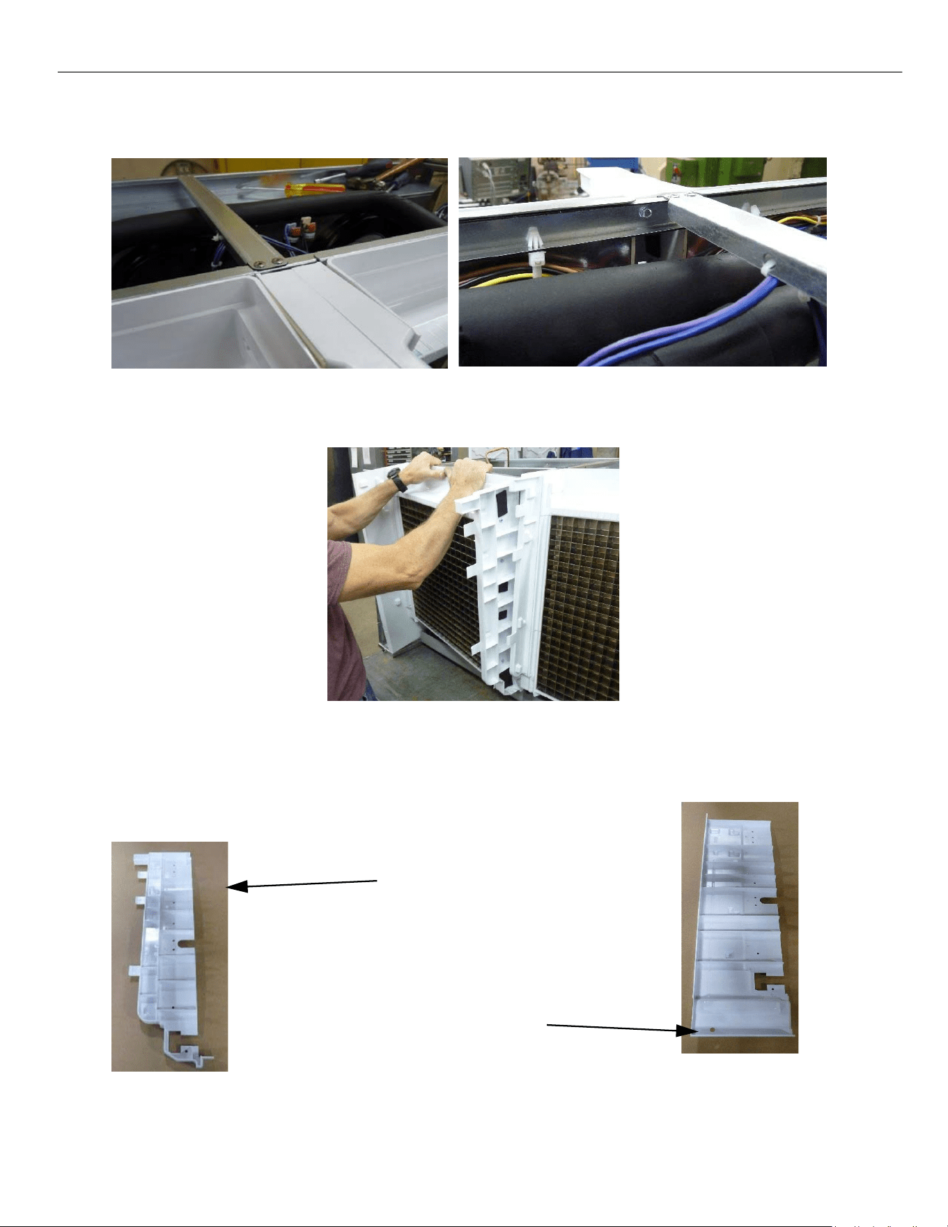
ELEVATION SERIES CIM CUBERS
EVAPORATOR REPLACEMENT
61
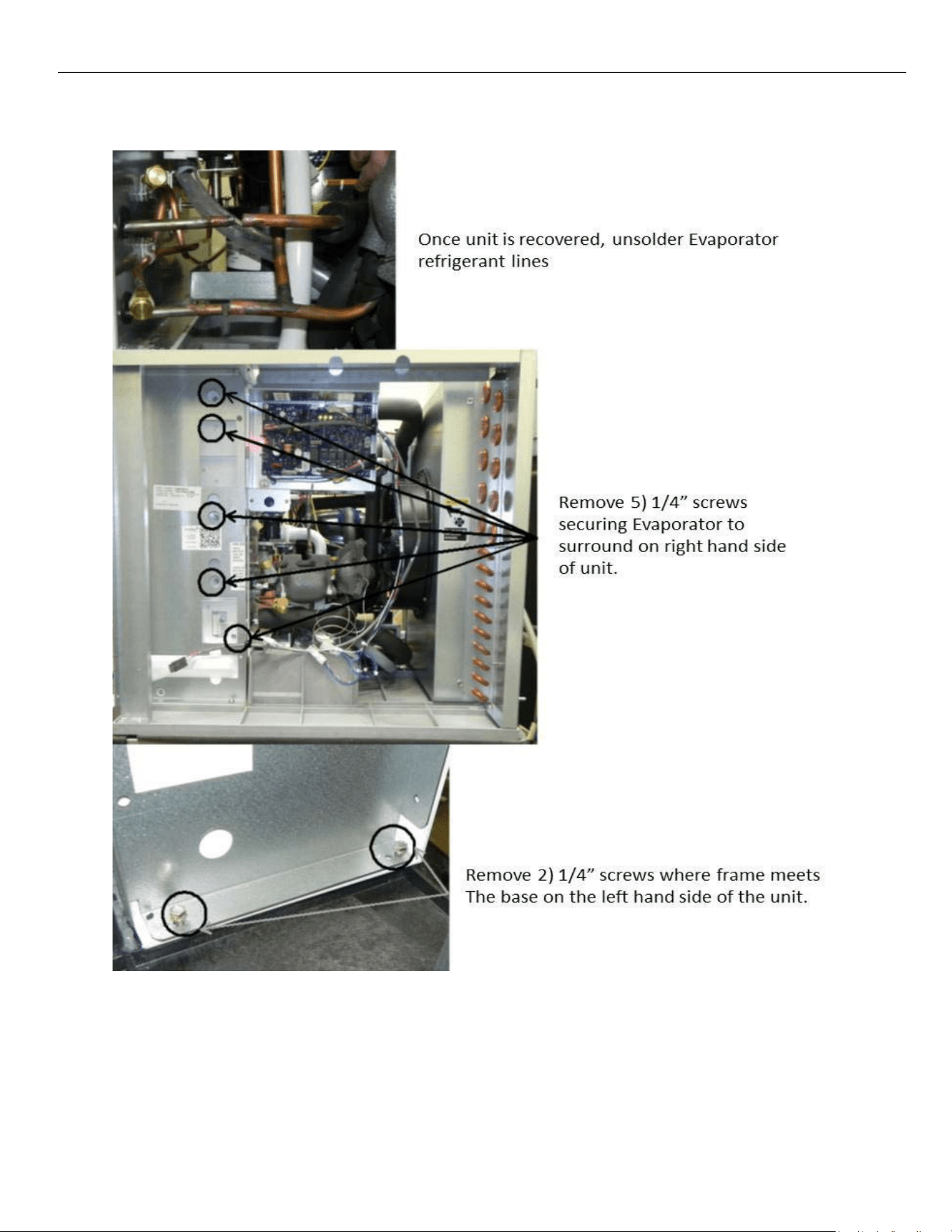
The new evaporator comes with two new side wall pieces. For a single evaporator unit, you will only use
the exterior right‐side wall that comes in the kit to replace the existing right‐side wall. This will allow the
new evaporator to be installed without interfering with the plastics. It has cut outs to allow for the new
refrigerant tube routing. For reference, see the image labeled “Exterior Right Wall” in the dual
evaporator replacement section for correct part identification.
Remove the right-hand side
wall and discard. You will
replace it with a new one
that is provided in the kit.
ELEVATION SERIES CIM CUBERS
EVAPORATOR REPLACEMENT
62
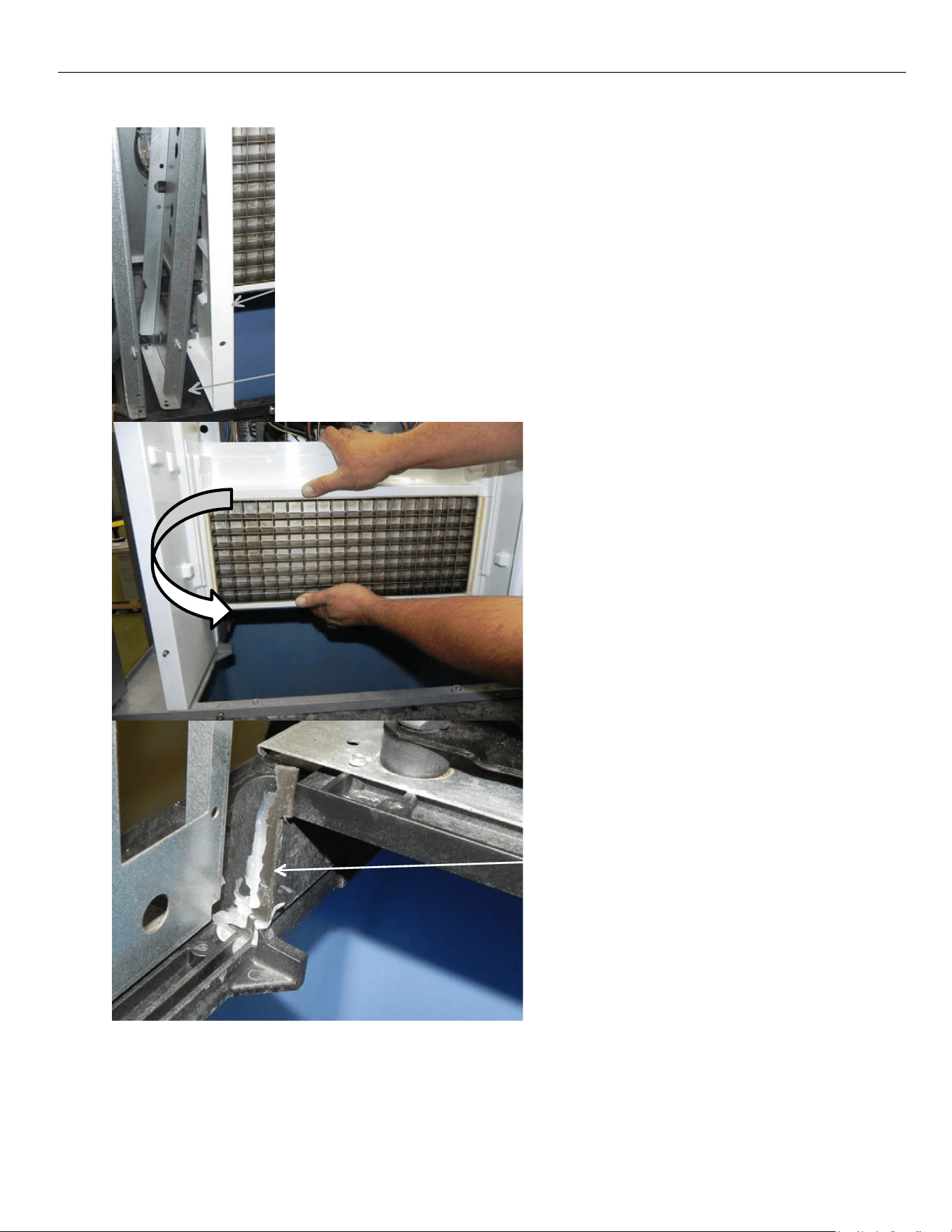
Surround
Pull the bottom of frame out to clear left‐hand surround.
Grasp and remove Evaporator freeing the
Left‐Hand side first. The Left‐Hand
Surround will come out with the
Evaporator; the Right‐Hand Surround will
be left in place. Once the Evaporator is out,
separate the surround from the Evaporator
by removing the five – 1/4” Screws on the
Left‐Hand side of the Evaporator. Remove
Curtain Switch on Right Hand side of
Evaporator and place on new Evaporator
and mount Left Hand Side surround on new
Evaporator.
Remove old silicone from base where shown
in picture. Run a 3/8” bead of silicone
included with Evaporator kit to replace
existing where surround and Evaporator
meet on the base.
Install Evaporator and reverse procedure for installation of components. Be sure to replace the Drier
on all open system repairs.
When reinstalling screws into the base be sure to not exceed a torque of 30in‐lb to avoid striping them.
ELEVATION SERIES CIM CUBERS
EVAPORATOR REPLACEMENT
63
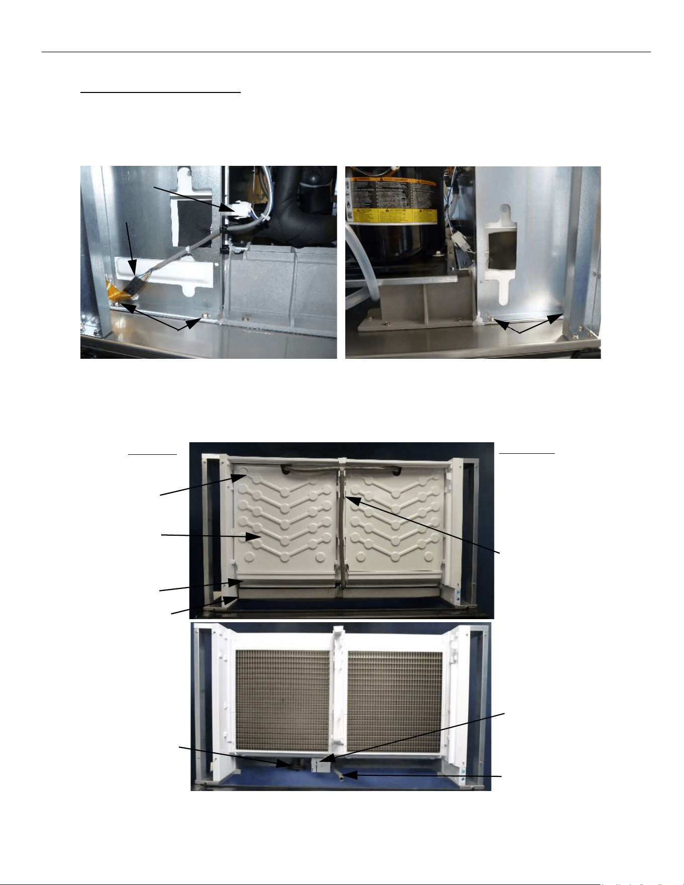
48in Dual Plate Evaporator Units
Recover the refrigerant from the unit. During the recovery, disconnect curtain switch and push pad ribbon
and move the wiring clear of the area. Remove the two mounting screws in the base of the unit near the
curtain switch. Depending on the one being replaced remove the left or right‐side screws.
Right Side of Unit Left Side of Unit
Remove the splash curtain, evaporator cover, top evaporator cover, water distribution tube, water pump
tube and its connector, sump, water pump, and float switch housing assembly.
Left Side
Right Side
Top cover
Evap. Cover
Curtain
Sump
Water
Distribution
Tubes
Water
Pump
Float Switch
Housing
Water Pump Tube
Curtain Switch
Ribbon
Mounting Screws
Mounting Screws
ELEVATION SERIES CIM CUBERS
EVAPORATOR REPLACEMENT
64
On the rear of the evaporator assembly, disconnect harvest assist assembly, purge valve and purge tube
and remove from the unit. Note there are two harvest assists, one for each plate. Make sure you
disconnect the proper one.
Harvest Assist
Purge Valve
Purge Tube
Once all the refrigerant is recovered. Remove the foam insulation from the evaporator plate tubing and Un‐
braze the evaporator tubes from the system so the plate is disconnected from the tubing system.
Remove the three ¼” screws along the back side of the evaporator holding it to the base in the machine
compartment.
Insulation to be
removed and
tubes un-brazed
Rear Mounting
Screws
ELEVATION SERIES CIM CUBERS
EVAPORATOR REPLACEMENT
65
Drill out the rivets that are holding the top middle cross beam to have access to the two top rear
mounting screws. Remove the corresponding screw to the evaporator you are working on.
With all the retaining screws out, and everything disconnected, you should now be able to rotate the
plate out of position for replacement with the new evaporator.
The new evaporator comes with two new side wall pieces. If replacing the left evaporator plate, you will
use the right interior wall. If replacing the right evaporator plate you will use the right‐side wall. These
new pieces have cut outs to accept the updated evaporator plate.
Interior Right Wall
Exterior Right Wall
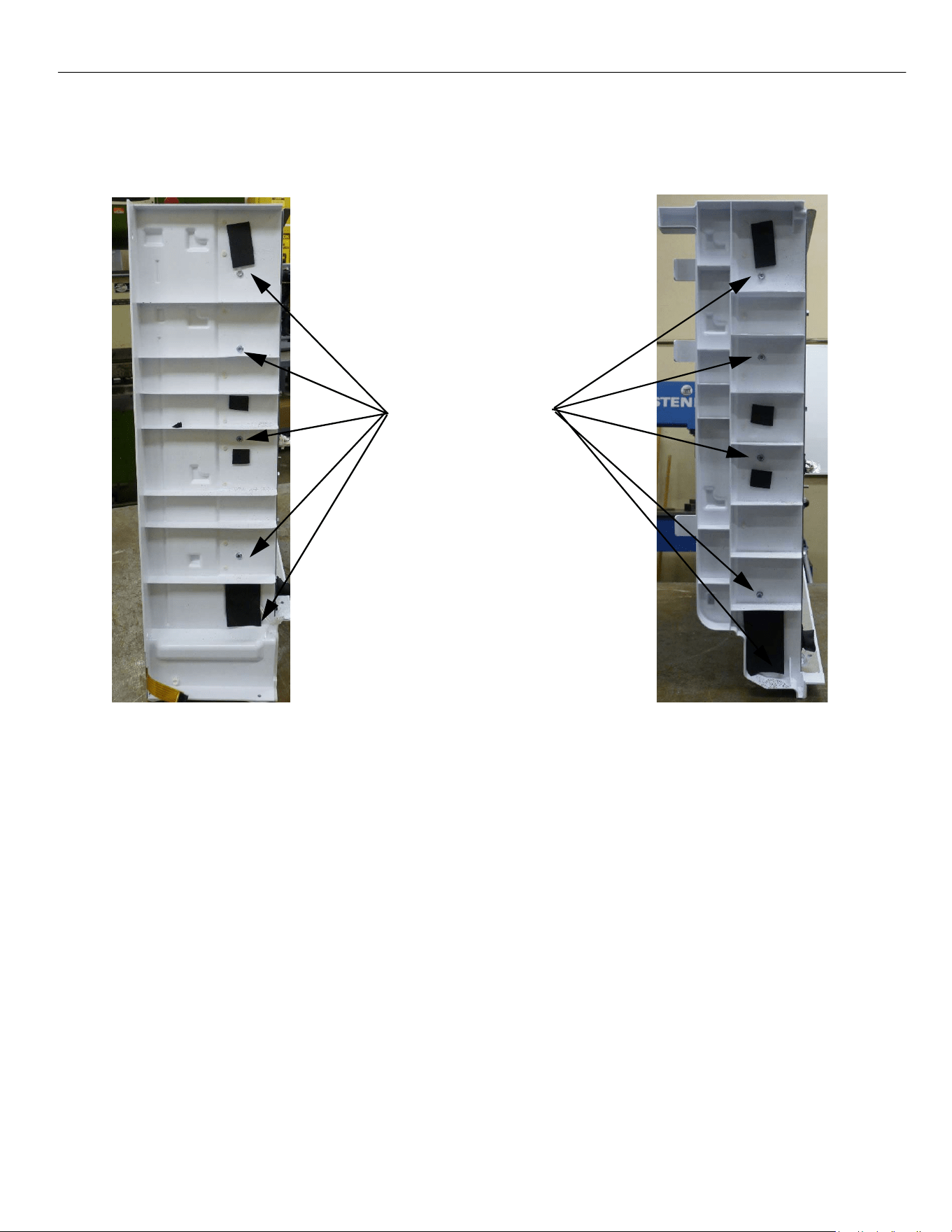
ELEVATION SERIES CIM CUBERS
EVAPORATOR REPLACEMENT
66
There are five screws holding both side walls on to the evaporator assembly. Remove them and the side
wall from the old assembly and reuse the screws to mount the new side walls to the new evaporator
plate assemblies.
Mounting Screw
locations for side
walls
Exterior Right Wall
Interior Right Wall
The left side walls from the old evaporators will be reused. Remove them from the old assemblies and
reattach them to the new evaporator. Reuse the screws from the old assemblies. Remove the old silicone
on the base where it interfaces with the evaporator. Add a new 3/8” bead of silicone to the corners and
flat face of the base before reinstalling new evaporator.
Once you have the side walls attached to the new evaporator. Reinstall the assembly in the reverse
order. When reinstalling screws into the base be sure to not exceed a torque of 30in‐lb to avoid striping
the base. Be sure to replace the filter dryer as well since it is an open system repair.
ELEVATION SERIES CIM CUBER
HIGH TEMP SAFETY
67
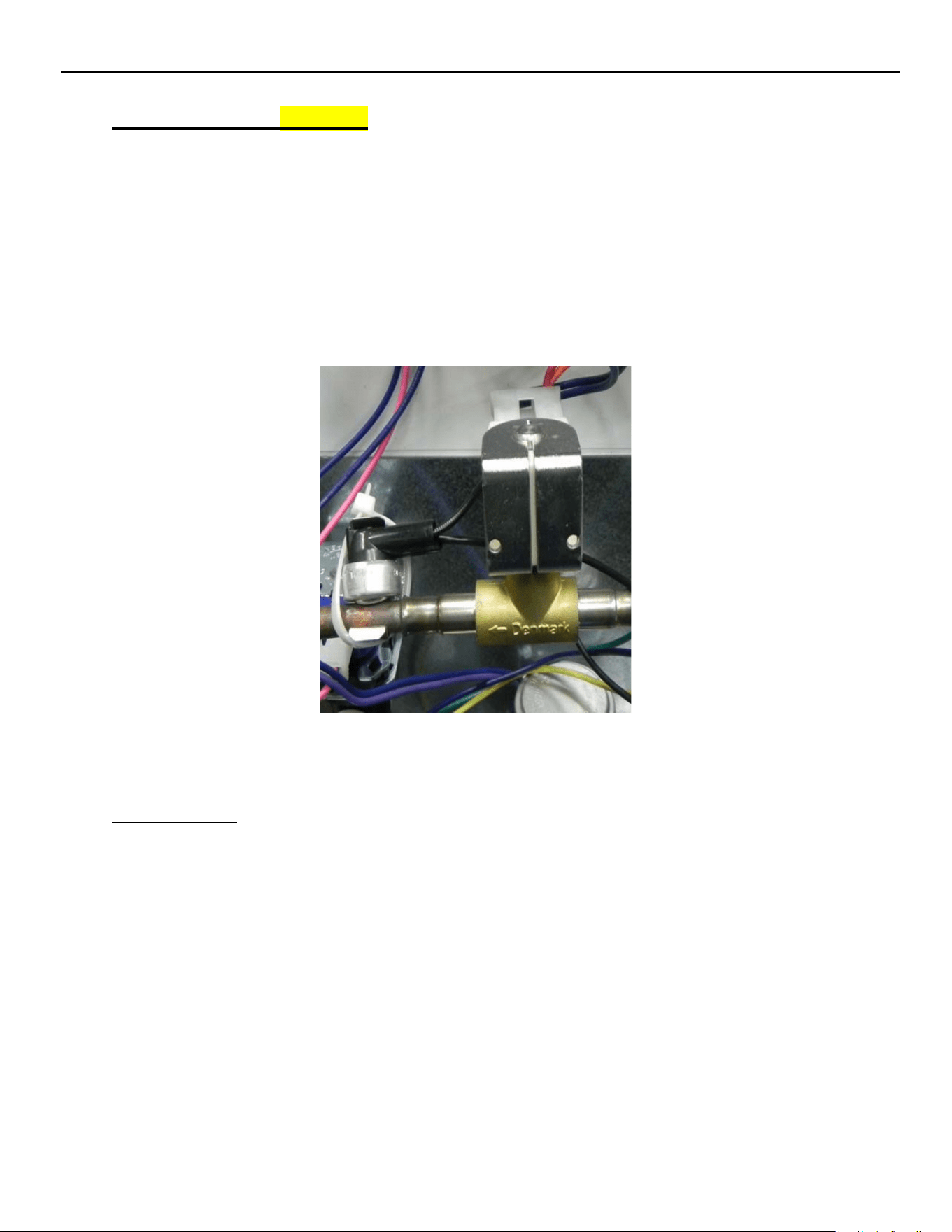
High Temp Safety (optional)
The High Temp Safety is a bi‐metal thermostat strapped to the line at the outlet of the Hot Gas
Valve. Should the Hot Gas Valve stick open, and the refrigerant line reach 180° F., the High
Temp Safety would open, dropping power to the Contactor and shut down the Compressor.
When the line temperature drops below 120° F., the contacts of the Safety will close, allowing
power to the Contactor.
Note: 48” units have two high temp safety switches connected in series, should either hot gas
circuit trigger a switch, it will shut down the compressor.
Troubleshooting
Should the Compressor not run with the R2 relay LED illuminated, verify if High Pressure Cutout
is closed and Contactor coil is good. The discharge line from the Hot Gas Valve should be cool to
the touch during a freeze cycle. With a line temperature below 120° F. (confirming hot gas valve
is closed), the contacts in the High Temp Safety should be closed. Disconnect both leads of the
High Temp Safety and check for continuity. If it open with a cool line, the safety will need to be
replaced.
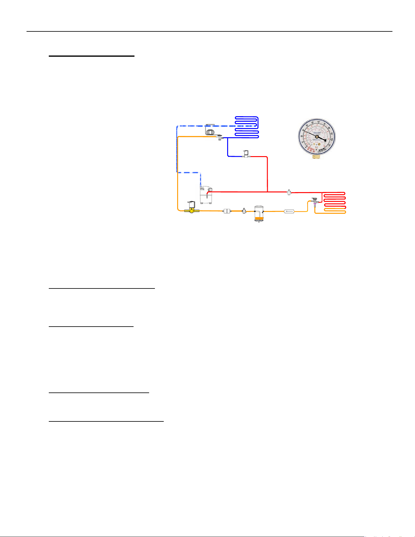
ELEVATION SERIES CIM CUBER
REFRIGERATION SECTION
68
Refrigeration Section
The Refrigeration Section on a CIM Cuber contains the Compressor, Thermostatic Expansion
Valve, Hot Gas Valve and Condenser. Remote systems also utilize a Mixing Valve (LAC), Liquid
Line Solenoid and Receiver. However, this section will vary as we Phase out R-404a and move
to more environmentally friendly refrigerants including R-449a, and R-290 refrigerants.
Refrigeration Section Operation
The Compressor drives the refrigeration system. Ice‐O‐Matic uses a Thermostatic Expansion
Valve to control refrigerant flow through the Evaporator.
Troubleshooting - System
When troubleshooting the refrigeration system, always use stub gauges to limit the amount of
refrigerant lost during connecting and disconnecting.
Always verify the refrigeration systems operating pressures when diagnosing any refrigeration
component. The Compressor should pull within 10% of the RLA when measured 5 minutes into
the Freeze Cycle and greater than 70% of RLA during the Freeze Cycle to be considered efficient.
Thermostatic Expansion Valve
The Thermostatic Expansion Valve meters refrigerant through the Evaporator.
Troubleshooting - Expansion Valve
First verify proper system pressures and charge. Verify the TXV bulb is securely mounted at 7
degrees off vertical (12:30 position) and well insulated. Generally, low suction pressure with a
normal head pressure will show poor ice formation top to bottom on the Evaporator and
indicate a low side restriction such as at the TXV. Should suction run high or not drop, verify bulb
connection to suction line and look for sweating or frosting on the dome of the Compressor
indicating TXV is stuck open.

ELEVATION SERIES CIM CUBERS
GENERAL MAINTENANCE
69
Hot Gas Valve
The Hot Gas Solenoid Valve opens to provide gas to the Evaporator during the Harvest Cycle.
Troubleshooting - Hot Gas Valve
Should the valve not open at the initiation of the Harvest Cycle (R3 LED ON), verify voltage at the
coil of the solenoid. If no voltage is present, verify Molex is properly connected at Board and
Voltage is present at Molex. If Voltage is present at coil, verify resistance through coil. If the coil
shows open, replace the coil. If the coil checks out, place magnetic donut on top of coil. If valve
will not open, replace the Hot Gas Valve body. Should suction pressure run high, check the
temperature of the inlet and outlet line of the Hot Gas Valve. It should be greater than 10‐
degree F. different. If less than 10 degrees F., the Valve is leaking and should be replaced. (See
also pg. 54.)
Liquid Line Solenoid
The Liquid Line Solenoid opens to allow refrigerant to flow from the Receiver on Remote
Systems. It is energized by R1 along with Remote Fan Motors. Diagnosis of Liquid Line Solenoid
is much the same as the Hot Gas Solenoid Valve (see above.)
Mixing Valve
The 220 psig. Mixing Valve (or LAC) Is used to maintain head pressure in low ambient.
Troubleshooting - Mixing Valve
In lower ambient temperatures, the Mixing Valve bypasses the Condenser to maintain head pressure.
During bypass mode, the inlet and outlet lines at the Condenser are at the same temperature. In
warmer ambient conditions, the Mixing Valve directs refrigerant to the Condenser Coil, resulting in
an approximate 20°F temperature difference. A low charge is indicated by hot inlet and outlet lines at
the Condenser and a hot Receiver. It is important to verify the system charge before determining if
the Mixing Valve is faulty.

ELEVATION SERIES CIM CUBERS
GENERAL MAINTENANCE
70
R-290 Troubleshooting
R‐290 is an A3 refrigerant, which refers to refrigerant grade propane (pure), a substance
that is odorless, highly flammable and displaces air as it is heavier than air. This
refrigerant has been used in the industry for several years. Specific precautions should
be taken when handling R‐290. Since R-290 is flammable, work in an open, well-
ventilated area.
Use appropriate tools to ensure safety.
o Combustible gas leak detector
o Tubing cutters
o Pinch-off tool
o Voltmeter
o Amp meter
o Temperature clamp probes
o Schrader taps
o Combustible gas Warning signs
o Refrigerant scale
o Vacuum pump
o Nitrogen
o R290 Temperature pressure Chart
All of the components work the same. But testing of the refrigeration section will be a little different.
Pressure will not be tested until the last resort as these units are critically charged.
Using a temperature pressure chart you can determine approx. pressure.
Measuring compressor amperage can show workload of the compressor to determine if the charge is
correct, restriction, or compressor performance. High amperage could be indicative of dirty condenser
coils, condenser fan motor, compressor beginning to fail, or low voltage to the compressor.
Low amperage could be a compressor motor weak or failing, low refrigerant charge, restriction, or the
valves in compressor not pumping
Using temperature clamps txv operation, hot gas valve operation, evaporator performance, and
condenser performance can be determined.
Units are sealed no Schrader ports and will need to be resealed after and refrigeration service.
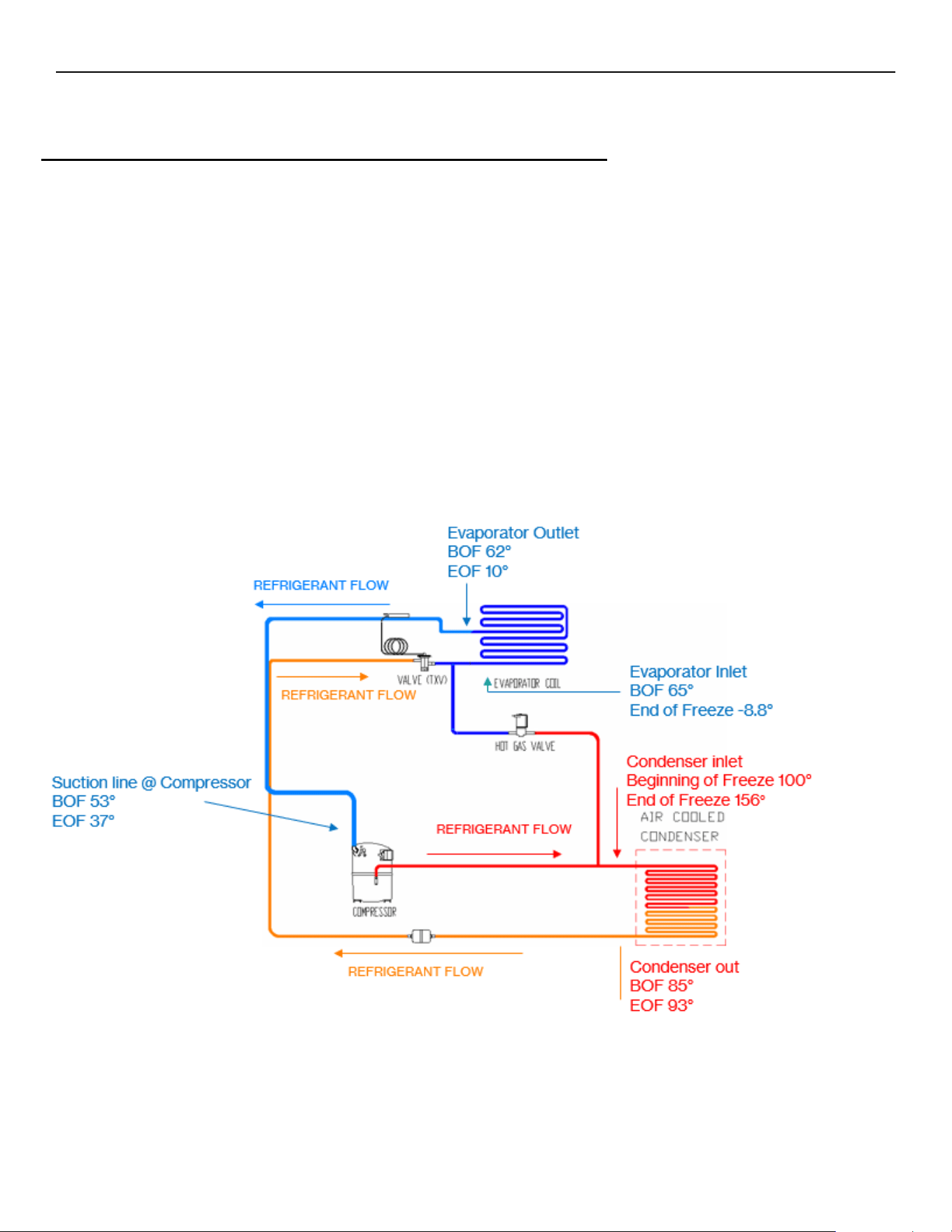
ELEVATION SERIES CIM CUBERS
GENERAL MAINTENANCE
71
Explanation of Refrigeration System
Understanding Freeze and Harvest Cycles in Ice Machines
The diagram referenced illustrates the flow of refrigerant through an ice machine’s components during both freeze and
harvest cycles. For R‐290 machine trouble shooting
Freeze Cycle
During the freeze cycle, refrigerant circulates from the compressor to the condenser via the discharge line. In the
condenser, heat exchange occurs: hot, high‐pressure gas releases its heat into the air and condenses into a warm, high‐
pressure liquid. This liquid proceeds through the thermal expansion valve (TXV), which meters the flow, resulting in a
cool, low‐pressure liquid. As this refrigerant absorbs heat from the water at the evaporator, it transforms into a cool,
low‐pressure gas, which is then drawn back to the compressor, completing the loop. The temperature and pressure can
be checked at various points —evaporator and condenser inlets and outlets—can be matched with a temperature‐
pressure chart for diagnostic purposes.
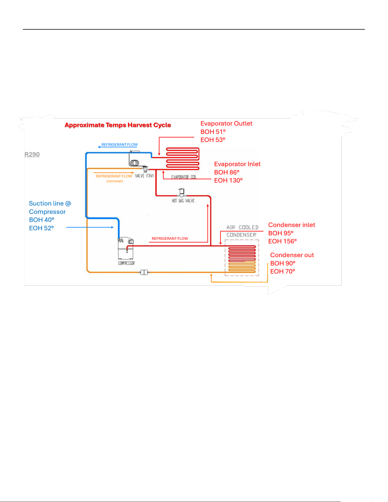
ELEVATION SERIES CIM CUBERS
GENERAL MAINTENANCE
72
Harvest Cycle
In the harvest cycle, the hot gas valve opens, redirecting hot, high‐pressure gas directly to the evaporator. This sudden
influx of heat raises the plate temperature above freezing, allowing ice to be released from the plates. At this stage, the
mixture of hot gas and cool liquid from the TXV ensures an efficient harvest. Proper timing is crucial; if the harvest
phase is too prolonged, it can cause overheating or lead to liquid flooding in the compressor, which may damage the
system.
Key Diagnostic and Maintenance Points
• Temperature-pressure charts help estimate system pressures for troubleshooting.
• Compressor amperage readings indicate if the compressor is working properly or if there are issues such as
restrictions, low charge, or failing components.
• Units are critically charged and sealed, lacking Schrader ports, so testing pressures is a last resort.
• Routine cleaning and maintenance, especially of the condenser and ice-making sections, are vital for reliable
operation and to maintain warranty coverage.
These diagrams help the technicians to assess performance and diagnose problems by following the refrigerant’s
path and monitoring system temperatures and pressures. Understanding the freeze and harvest cycles enables
efficient troubleshooting and ensures the longevity of the ice machine.

ELEVATION SERIES CIM CUBERS
GENERAL MAINTENANCE
73
General Maintenance
Electrical shock and/or injury from moving parts inside this machine can cause serious injury.
Disconnect electrical supply to machine prior to performing any adjustments or repairs.
Failure to perform the required maintenance at the frequency specified will void warranty coverage
in the event of a related failure.
General Maintenance Procedure
To ensure economic, trouble-free operation of your machine, it is recommended that the following maintenance be
performed every 6 months.
1.
Clean the ice-making section per the instructions below. Cleaning should be performed
at a minimum of every 6 months. Local water conditions may require that cleaning be
performed more often.
2.
Check ice bridge thickness. See page 14 for proper thickness and adjustment
procedure.
3.
Check water level in Sump. See page 47 for proper water level and adjustment
procedure.
4.
Clean the condenser (air-cooled machines) to ensure unobstructed air flow.
5.
Check for leaks of any kind: water, refrigerant, oil, etc.
6.
Check the bin control switch (if applicable) for proper adjustment.
7.
Check the Water Regulating Valve (water cooled machine) for proper adjustment by
measuring the discharge pressure which should be adjusted to maintain 250 psi (17.01 bar/
1.723 MPa). Adjust the water regulating valve as required. Water exiting the condenser
should be between
100°F (38°C) and 110°F (43°C).
8.
Check all electrical connections.
9.
Oil the fan motor if the motor has an oil fitting. (Self-contained air-cooled models only)
10.
Check the water filter (if applicable) and replace it if dirty or restricted
11.
Inspect the evaporator water distribution tube to insure even distribution of water
across the face of the evaporator.
12.
Clean Remote Condenser if applicable.
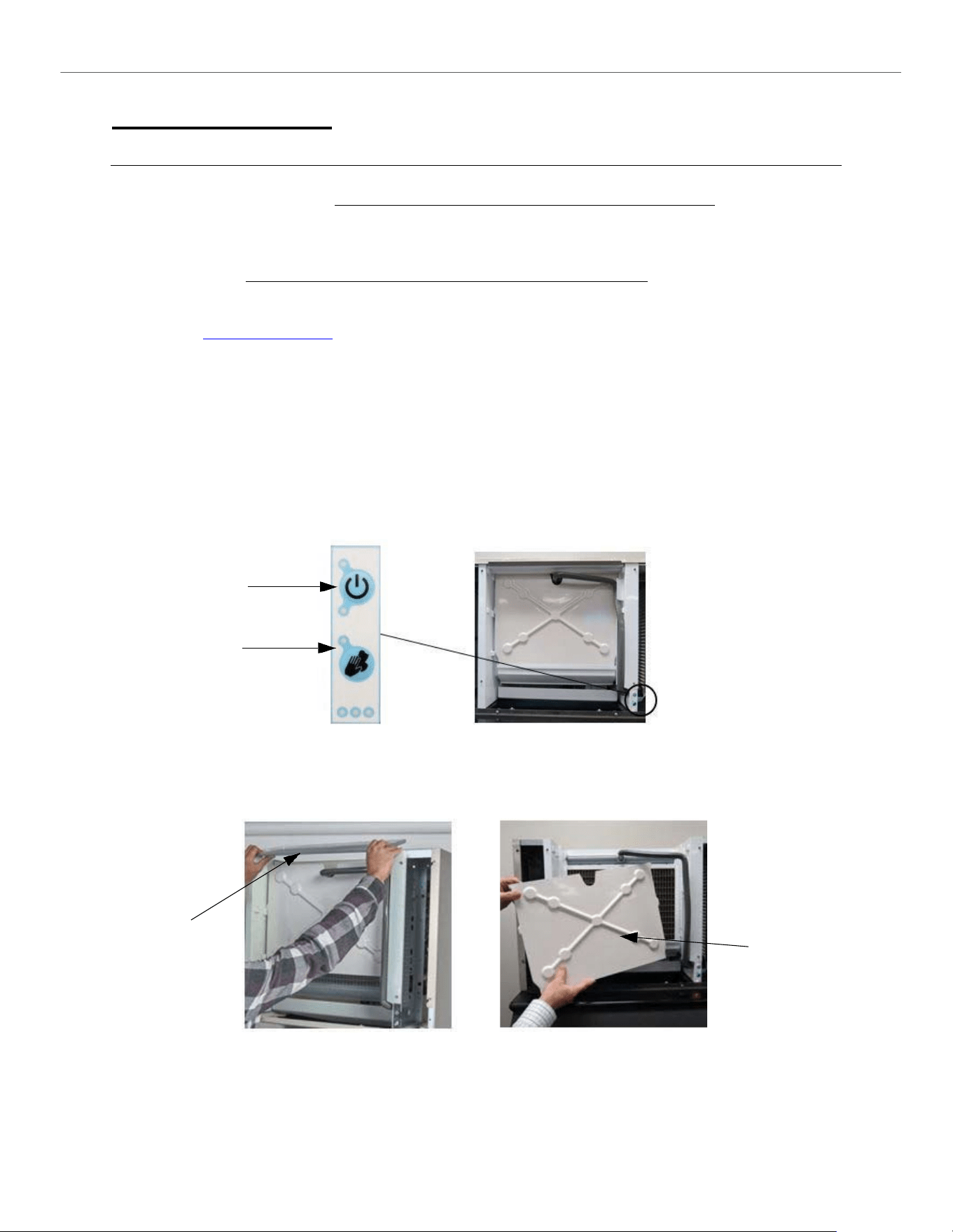
ELEVATION SERIES
CLEANING/SANITIZING PROCEDURES
74
Cleaning and Sanitizing
Cleaning Instruction for Ice-O-Matic CIM Series Ice Machines
Note: Proper cleaning of an ice machine requires two parts: descaling and sanitizing.
Descaling should be scheduled at a minimum of twice per year but no more than once per month.
Descaling dissolves the mineral deposits on the evaporator and other surfaces. It removes scale, calcium, lime
scale and other mineral buildup. Ice-O-Matic requires a “nickel-safe” cleaner such as Nu-Calgon Nickel-Safe Ice
Machine Cleaner or equivalent diluted per manufacturer’s instructions.
Sanitizing should be performed after each descaling but no more than once per month.
Sanitizing disinfects the machine and removes microbial growth including mold and slime. Ice-O-Matic requires
a “nickel-safe” sanitizer such as Nu-Calgon IMS-III or equivalent diluted per manufacturer’s instructions.
Please refer to www.iceomatic.com for approved chemical formulations and proper pH balance.
CAUTION: Do not mix cleaner (descaler) and sanitizer together.
Eye protection is recommended when handling descaler or sanitizer.
Wear protective rubber gloves when handling descaler or sanitizer.
Note: Electrical power will be ON when performing the following cleaning instructions.
1.
Remove all ice from storage means to prevent any contamination of ice in storage.
2.
Remove the front panel of the ice machine by loosening the two front panel screws with a Phillips head
screwdriver. Lift panel to remove.
3.
Press and hold the POWER button for 3 seconds to initiate a harvest cycle (blue light will begin to flash for
Manual Harvest mode). This ensures there is no ice on the plate and the water is emptied from the sump.
Power Button
Clean Button
4.
Once the ice machine has completed its harvest cycle, the POWER light will go to solid red (OFF mode).
5.
Remove the upper evaporator cover and leave the lower curtain.
Top Cover
Evaporator cover
(Slide up and Lift Off)
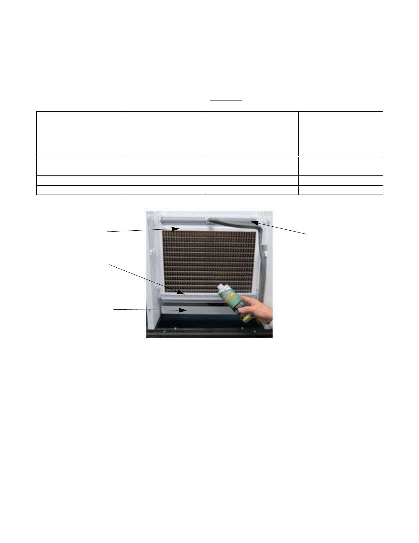
ELEVATION SERIES
CLEANING/SANITIZING PROCEDURES
75
6.
Quick press the CLEAN button to start the process. The ice machine will show a solid red and flashing yellow
light during the cleaning cycle. Units cannot be brought out of clean mode once clean mode is started.
7.
The machine will first verify that the sump is empty with the pump ON, and the purge valve energized.
8.
When the sump is mostly empty, the machine will begin to fill the sump (about 30 seconds to a minute).
9.
The pump turns ON when the water fill reaches the proper fill level. Measure the appropriate amount of descaler
according to the machine size and sump volume from chart below. Carefully pour the descaler into the sump
using the lower curtain to prevent splash. Replace the upper evaporator cover.
Model
Sump Size (volume)
Gallons (in liters)
Example: Nu-Calgon Nickel-
Safe Ice Machine Cleaner
Descaler Concentration Ratio
5 fl.oz. per 1 gal. of water
(39 mL per 1 Liter of water)
Example Nu-Calgon IMS-III
Sanitizer Concentration Ratio
1.6 fl. oz. per 1 gal. of water
(12.5 mL per 1 Liter of water)
CIM0320/0330
.9 (3.4)
Add 4.5 fl. oz. (133mL)
Add 1.5 fl. oz. (44mL)
CIM0430/0520/0530/0630
1.2 (4.5)
Add 6 fl. oz. (177mL)
Add 2 fl. oz. (59mL)
CIM0820/0830/1120/1130
1.1 (4.2)
Add 5.5 fl. oz. (164mL)
Add 1.8 fl. oz. (53mL)
CIM1440/1540/1840/2040
1.8 (6.8)
Add 9.0 fl. oz. (265mL)
Add 2.9 fl. oz. (85mL)
Spillway
Lower Curtain
Sump
Distribution Tube
Use Lower Curtain to direct
cleaner into Sump
10.
The machine will remain in the WASH cycle for 15 minutes.
11.
After WASH time, the machine will PURGE and re-fill with the water pump ON.
12.
The machine will RINSE (less than one minute) then repeat PURGE/FILL/RINSE multiple times.
13.
The machine will end the cleaning cycle with a mostly empty sump and a solid red and yellow light.
14.
Quick press the CLEAN button to return to OFF mode.
15.
Remove the upper evaporator cover and lower evaporator curtain. Using a solution with the proper concentration
of cleaner (descaler or sanitizer), wipe down with a clean, soft cloth the evaporator, water spillway, water
distributor, upper evaporator cover, lower evaporator curtain and all splash surfaces. Verify that all residue and
residual minerals have been removed.
16.
If a full clean of water components is required, this can be done by referring to the service manual for water
system component breakdown. This is recommended to be done by a qualified service agent.
17.
Re-assemble all ice machine water system components in reverse order.
18.
Sanitizing the ice machine is recommended after descaling. Repeat the process with sanitizer at the correct ratio.
19.
It is recommended to clean (descale and sanitize) the storage means after cleaning the ice machine.
20.
Quick press the POWER button to return the ice machine to the ice making cycle.
21.
Replace the front panel and tighten the two panel screws with a Phillips screwdriver.
ELEVATION SERIES CIM CUBERS
CABINET CARE
76
Cabinet Care
Chemicals for Descaling and Sanitizing
It is important to use solutions that do not harm the ice machine. Never use cleaning or sanitizing solutions that
contain Nitric Acid, Sulfuric Acid, Hydrochloric Acid, Carbolic Acid, Acetic Acid, diluted Acetic Acid or non-
food-grade vinegar (concentration of acetic acid greater that 6% and does not contain enzymes created in
processing) or any chlorine-based solution such as bleach, chlorine dioxide or any type of salts such as
potassium chloride (potassium salts) or sodium chloride. Check the label or the manufacturer’s Material Safety
Data Sheet (MSDS) to be sure. These chemicals can attack the surface of the evaporator as well as other metal
components causing corrosion and flaking. Using the incorrect cleaner or sanitizer will void the warranty
of the unit
Please refer to www.iceomatic.com for approved chemical formulations and proper pH balance.
Cleaning Stainless Steel and Aluminum
Commercial grades of stainless steel and aluminum are susceptible to rusting or corrosion if not properly
maintained. It is important that you properly care for the stainless steel and aluminum surfaces of your ice
machine and bin to avoid the possibility of rust or corrosion.
Use the following recommended guidelines for keeping your machine looking like new:
1.
Clean the stainless steel and aluminum thoroughly once a week. Clean frequently to avoid
the build-up of hard, stubborn stains. Hard water stains left to sit can weaken the metals
corrosion resistance and lead to rust or corrosion. Use a nonabrasive cloth or sponge,
working with, not across, the grain.
2.
Do not use abrasive tools to clean the metal surface. Do not use steel wool, abrasive sponge
pads, wire brushes or scrapers to clean the metal.
3.
Do not use cleaners that use chlorine or chlorides. Do not use chlorine bleach products to
clean the metal surfaces. Chlorides break down the metals protective layer.
4.
Rinse with clean water. If chlorinated cleansers are used, you must thoroughly rinse the sur-
face with clean water and wipe dry immediately.
5.
Use the right cleaning agent. The table below lists the recommended cleaning agents for com-
mon metal cleaning problems.
Cleaning Activity
Cleaning Agent
Method of Application
Routine Cleaning
Mild dish soap, ammonia, glass
cleaner, or mild detergent with
water. Household kitchen cleaning
chemicals approved for metal
surfaces.
Apply with clean cloth or sponge.
Rinse with clean water and wipe
dry.
Removing grease or fatty acids
Oven cleaners
Apply generously; allow to stand
for 15-20 minutes. Rinse with
clean water. Repeat as required.
Removing hard water spots and
scale
Vinegar
Swab or wipe with clean cloth.
Rinse with water and wipe dry.
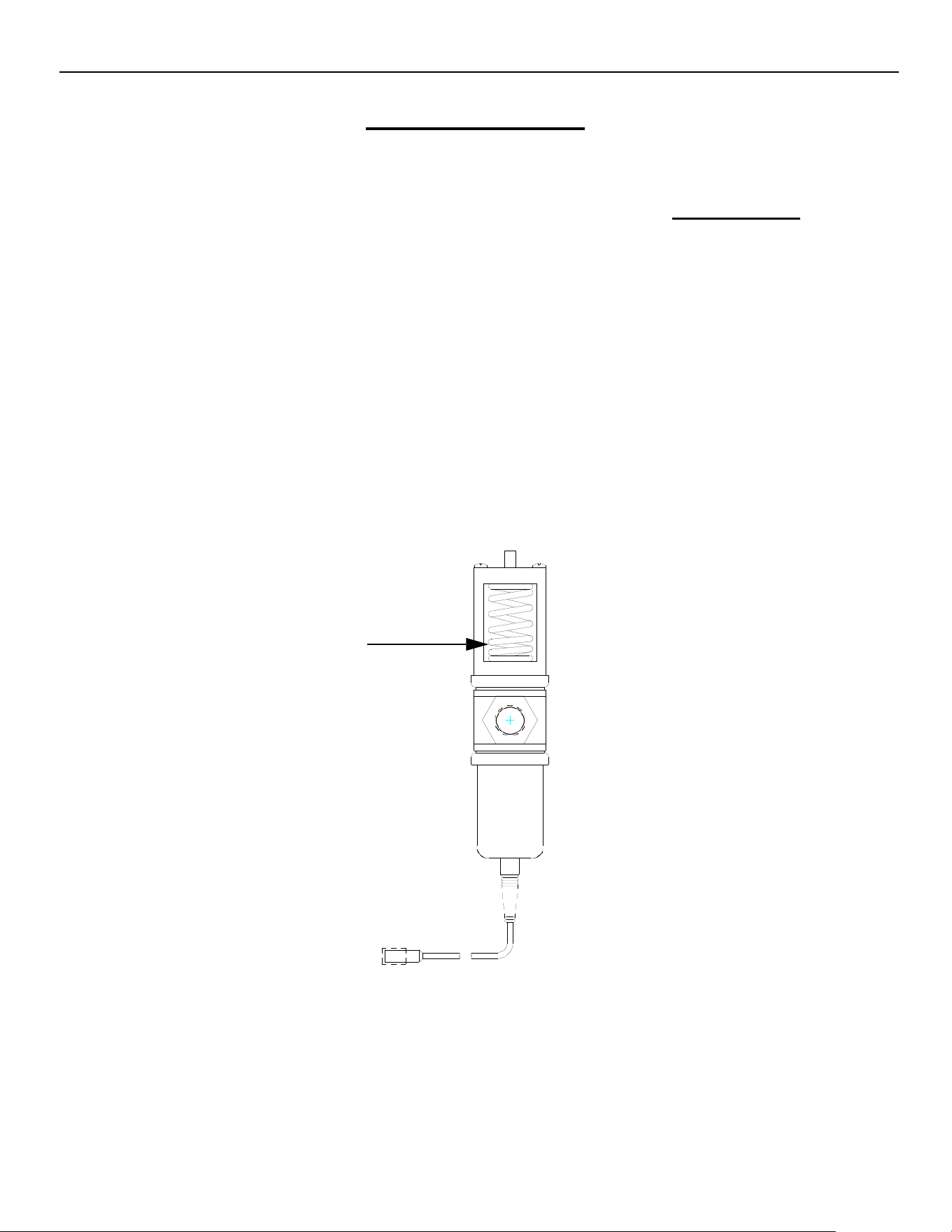
ELEVATION SERIES CIM CUBERS
WINTERIZING PROCEDURES
77
Winterizing Procedures
IMPORTANT: Whenever the ice machine is taken out of operation during the winter months, the procedure
below must be performed. Failure to do so may cause serious damage and will void all warranties.
1. Turn off water to machine.
2. Make sure all ice is off of the evaporator(s). If ice is being made, initiate harvest by pressing the
Power Button for approximately 3 seconds. The unit will shut off automatically following the
harvest.
3. Disconnect the tubing between the water pump discharge and water distribution tube and drain
any water.
4. On water cooled machines, hold the water regulating valve open by prying upward on the water
valve spring with a screwdriver while using compressed air to blow all the water out of the con-
denser.
5. Remove all of the ice in the storage bin and discard.

Model
Voltage/Hz/
Phase
Approx.
S
uction
Press
Approx.
Head
Press
Avg. Batch
Half/Full
Approx.
Cycle
Time
90/70
in Min.
Avg. Water Usage per
100 lbs. Produced in
Gallons
Min
Circuit
Amps
Max
Fuse
size
kWH
Used
Comp.
LRA
Comp.
RLA
Ref.
Type
Charge in
ounces
Potable
Water Cond.
CIM0320A
115/60/1
50‐30
175‐400
3.025/3.375
18‐23
20.0
11.0
15
6.69
50.0
8.1
R‐404a
20
CIM0320W
115/60/1
50‐30
250
3.025/3.375
16‐21
19.6
179
10.7
15
5.19
50.0
8.1
R‐404a
13
CIM0320A90
115/60/1
45‐15
175‐245
3.025‐3.375
15‐23
19.0
11.4
15
5.81
44.0
8.3
R‐290
4.94
CIM0325A
220‐240/50/1
50‐30
175‐400
3.025/3.375
19‐24
22.0
6.9
16
7.32
29.5
5.1
R‐404a
22
CIM0325W
220‐240/50/1
50‐30
250
3.025/3.375
16‐21
20.0
187.5
6.8
16
5.53
29.5
5.1
R‐404a
13
CIM0326A
208‐230/60/1
50‐30
175‐400
3.025/3.375
18‐23
24.0
6.5
15
6.8
26.5
4.6
R‐404a
22
CIM0330A
115/60/1
50‐30
175‐400
3.025/3.375
18‐23
20.0
11.0
15
6.69
50.0
8.1
R‐404a
20
CIM0330W
115/60/1
50‐30
250
3.025/3.375
16‐21
19.6
179
10.7
15
5.19
50.0
8.1
R‐404a
13
CIM0330A90
115/60/1
45‐15
175‐245
3.025‐3.375
16‐21
19.0
11.4
15
5.81
44.0
8.1
R‐290
4.94
CIM0335A
220‐240/50/ 1
50‐30
175‐400
3.025/3.375
19‐24
22.0
6.9
16
7.32
29.5
5.1
R‐404a
22
CIM0430A
115/60/1
50‐30
175‐400
5.025/5.65
22‐26
19.8
11.0
15
5.43
50.0
8.1
R‐404a
24
CIM0430W
115/60/1
50‐30
250
5.025/5.65
19‐22
17.8
169
10.7
15
4.75
50.0
8.1
R‐404a
14
CIM0430A90
115/60/1
45‐15
175‐245
5.025‐5.65
16‐21
17.0
11.4
15
4.95
44.0
8.3
R‐290
4.94
CIM0435A
220‐240/50/1
50‐30
175‐400
5.025/5.65
20‐24
20.0
8.7
16
5.97
37.0
6.3
R‐404a
24
CIM0436A
115/60/1
50‐30
175‐400
5.025/5.65
17‐20
18.0
6.3
15
5.46
26.5
4.6
R‐404a
24
CIM0436W
115/60/1
50‐30
250
5.025/5.65
20‐24
17.7
185
6.1
15
4.37
26.5
4.6
R‐404a
14
CIM0520A
115/60/1
50‐30
175‐400
5.025/5.65
18‐22
19.9
17.8
30
5.87
70.0
13.5
R‐404a
20
CIM0520W
115/60/1
50‐30
250
5.025/5.65
15‐18
20.0
181
17.4
30
4.7
70.0
13.5
R‐404a
14
CIM0520A90
115/60/1
45‐15
175‐245
5.025/5.65
16‐21
17.0
11.9
20
5.43
55.0
8.7
R‐290
4.59
CIM0525A
220‐240/50/1
50‐30
175‐400
5.025/5.65
18‐21
20.0
11.2
16
6.11
38.0
8.5
R‐404a
22
CIM0525W
220‐240/50/1
50‐30
250
5.025/5.65
15‐18
19.5
190
11.0
16
5.00
38.0
8.5
R‐404a
14
CIM0526A
208‐230/60/1
50‐30
175‐400
5.025/5.65
17‐21
20.0
8.2
15
5.02
33.7
6.1
R‐404a
22
CIM0530A
115/60/1
50‐30
175‐400
5.025/5.65
18‐22
19.9
17.8
30
5.87
70.0
13.5
R‐404a
20
CIM0530W
115/60/1
50‐30
250
5.025/5.65
15‐18
20.0
181
17.4
30
4.7
70.0
13.5
R‐404a
14
CIM0530A90
115/60/1
45‐15
175‐245
5.025/5.65
16‐21
17.0
11.9
20
5.43
55.0
8.7
R‐290
4.59
CIM0530R49
115/60/1
45‐25
220‐400
5.025/5.65
17‐21
17.0
20.1
30
5.08
70.0
15
R‐449a
125
CIM0530R
115/60/1
50‐30
220‐400
5.025/5.65
17‐21
19.6
20.1
30
6.21
70.0
13.5
R‐404a
132
CIM0535A
220‐240/50/1
50‐30
175‐400
5.025/5.65
18‐21
20.0
11.2
16
6.11
38.0
8.5
R‐404a
22
CIM0535W
220‐240/50/1
50‐30
250
5.025/5.65
16‐19
19.5
190
11.0
16
5
38.0
8.5
R‐404a
13
CIM0535R
220‐240/50/1
50‐30
220‐400
5.025/5.65
17‐20
20.0
12.0
20
6.31
38.0
8.5
R‐404a
132
CIM0635A
220‐240/50/1
50‐30
175‐400
5.025/5.65
16‐19
20.0
8.1
16
5.72
37.0
5.8
R‐404a
22
CIM0636A
208‐230/60/1
50‐30
175‐400
5.025/5.65
16‐19
18.6
9.2
15
5.63
46.0
6.9
R‐404a
20
CIM0636W
208‐230/60/1
50‐30
250
5.025/5.65
14‐16
19.2
180
9.0
15
4.27
46.0
6.9
R‐404a
14
CIM0636A90
208‐23/60/1
45‐15
175‐245
5.025/5.65
16‐21
17.0
8.1
15
4.53
35.0
6.0
R‐290
4.94
CIM0636R49
208‐230/60/1
45‐25
220‐400
5.025/5.65
14‐16
18.5
15
15
5.20
46.0
7.7
R‐449a
125
ELEVATION SERIES CIM CUBERS
Technical Specifications
TECHNICAL SPECIFICATIONS
68
ELEVATION SERIES CIM CUBERS
TECHNICAL SPECIFICATIONS
69

Model
Voltage/Hz/
Phase
Approx.
Suction
Press
Approx.
Head
Press
Avg. Batch
Half/Full
Approx
Cycle
Time
90/70in
Minutes
Avg. Water Usage per
100 lbs. Produced in
Gallons
Min
Circuit
Amp.
Max
Fuse
size
kWH
Used
Comp.
LRA
Comp.
RLA
Ref.
Type
Charge in
ounces
Potable
Water Cond.
CIM0636R
208‐230/60/1
50‐30
220‐400
5.025/5.65
14‐16
19.0
10.0
15
5.29
46
6.9
R‐404a
132
CIM0825A
220‐240/50/1
50‐30
175‐400
7.15/8.10
17‐21
18.0
13.3
20
4.73
55.0
9.7
R‐404a
40
CIM0825R
220‐240/50/1
50‐30
220‐400
7.15/8.10
15‐18
18.0
13.7
20
4.38
55.0
9.7
R‐404a
176
CIM0826A
208‐230/60/1
50‐30
175‐400
7.15/8.10
17‐20
19.0
13.4
20
5.0
56.0
9.8
R‐404a
40
CIM0826A49
208‐230/60/1
45‐25
175‐400
7.15/8.10
17‐20
17.5
13.3
20
4.69
56.0
9.8
R‐449a
40
CIM0826W
208‐230/60/1
50‐30
250
7.15/8.10
17‐20
19.0
140
12.8
20
4.2
56.0
9.8
R‐404a
30
CIM0826R
208‐230/60/1
50‐30
220‐400
7.15/8.10
16‐19
19.0
13.8
20
4.9
56.0
9.8
R‐404a
176
CIM0826R49
208‐230/60/1
45‐25
220‐400
7.15/8.10
16‐19
17.5
13.7
20
4.69
56.0
9.8
R‐449a
176
CIM0835A
220‐240/50/1
50‐30
175‐400
7.15/8.10
16‐19
18.0
13.3
20
4.73
55.0
9.7
R‐404a
40
CIM0835GA
220‐240/50/1
50‐30
175‐400
8.6
17‐20
18.0
15.2
20
5.7
58.0
11.2
R‐404a
38
CIM0835W
220‐240/50/1
50‐30
250
7.15/8.10
16‐19
18.0
110
12.7
20
3.96
55.0
9.7
R‐404a
28
CIM0835R
220‐240/50/1
50‐30
220‐400
7.15/8.10
16‐19
18.0
13.7
20
4.38
55.0
9.7
R‐404a
176
CIM0836A
208 230/60/1
50‐30
175‐400
7.15/8.10
16‐19
19.0
13.4
20
5
56.0
9.8
R‐404a
40
CIM0836A49
208‐230/60/1
45‐25
175‐400
7.15/8.10
16‐19
17.5
13.3
20
4.69
56.0
9.8
R‐449a
40
CIM0836W
208‐230/60/1
50‐30
250
7.15/8.10
16‐19
19.0
140
12.8
20
4.2
56.0
9.8
R‐404a
30
CIM0836R
208‐230/60/1
50‐30
220‐400
7.15/8.10
16‐19
19.0
13.8
20
4.9
56.0
9.8
R‐404a
176
CIM0836R49
208‐230/60/1
45‐25
220‐400
7.15/8.10
16‐19
18.0
13.8
20
4.69
56.0
9.8
R‐449a
40
CIM0836GA
208‐230/60/1
50‐30
175‐400
8.6
17‐20
19.0
13.9
20
5.4
78.0
10.2
R‐404a
38
CIM1125A
220‐240/50/1
50‐30
175‐400
7.15/8.10
16‐19
18.0
15.2
25
5.2
58.0
11.2
R‐404a
36
CIM1125R
220‐240/50/1
50‐30
220‐400
7.15/8.10
11‐15
18.0
15.6
25
4.6
58.0
11.2
R‐404a
176
CIM1126A
208‐230/60/1
50‐30
175‐400
7.15/8.10
11‐15
19.0
13.9
20
5.1
78.0
10.2
R‐404a
40
CIM1126A49
208‐230/60/1
45‐25
175‐400
7.15/8.10
11‐15
18.0
13.8
20
4.69
78.4
10.2
R‐449a
40
CIM1126W
208‐230/60/1
50‐30
250
7.15/8.10
11‐15
19.0
140
13.3
20
4.1
78.0
10.2
R‐404a
32
CIM1126R
208‐230/60/1
50‐30
220‐400
7.15/8.10
11‐15
19.0
14.3
20
5.1
78.0
10.2
R‐404a
176
CIM1126R49
208‐230/60/1
45‐25
220‐400
7.15/8.10
11‐15
18.0
13.8
20
4.75
78.4
10.2
R‐449a
176
CIM1135A
220‐240/50/ 1
50‐30
175‐400
7.15/8.10
11‐15
18.0
15.2
25
5.2
58.0
11.2
R‐404a
36
CIM1135W
220‐240/50/1
50‐30
250
7.15/8.10
11‐15
18.0
110
14.6
25
4.2
58.0
11.2
R‐404a
32
CIM1135R
220‐240/50/1
50‐30
220‐400
7.15/8.10
11‐15
18.0
15.6
25
4.6
58.0
11.2
R‐404a
176
CIM1136A
208‐230/60/1
50‐30
175‐400
7.15/8.10
11‐15
19.0
13.9
20
5.1
78.0
10.2
R‐404a
40
CIM1136W
208‐230/60/1
50‐30
250
7.15/8.10
11‐15
19.0
140
13.3
20
4.1
78.0
10.2
R‐404a
32
Model
Voltage/Hz/
Phase
Approx.
S
uction
Press
Approx.
Head
Press
Avg. Batch
Half/Full
Approx
Cycle
Time
90/70in
Minutes
Avg. Water Usage per
100
lbs. Produced in
Gallons
Min
Circuit
Amp.
Max
Fuse
size
kWH
Used
Comp.
LRA
Comp.
RLA
Ref.
Type
Charge in
ounces
Potable
Water Cond.
CIM1136R
208‐230/60/1
50‐30
220‐400
7.15/8.10
11‐15
19.0
14.3
20
5.1
78.0
10.2
R‐404A
176
CIM1136R49
208‐230/60/1
45‐25
220‐400
7.15/8.10
11‐15
18.0
14.2
20
4.75
78.4
10.2
R‐449a
176
CIM1137A
208‐230/60‐1
50‐30
175‐400
7.15/8.10
11‐15
19.0
9.5
15
5.1
51.0
6.7
R‐404a
40
CIM1137W
208‐230/60/1
50‐30
250
7.15/8.10
11‐15
19.0
140
8.9
15
4.1
51.0
6.7
R‐404a
32
CIM1137R
208‐230/60/1
50‐30
220‐400
7.15/8.10
11‐15
19.0
9.9
15
4.9
51
6.7
R‐404a
176
CIM1446A49
208/230/60/1
45/25
175‐400
14.3/16.2
17‐20
14.4
19.2
30
4.4
73
13.9
R‐449a
58
CIM1446W
208/230/60/1
50‐30
250
14.3/16.2
16‐19
14.7
103.96
18.9
30
3.72
82.0
14.4
R‐404a
30
CIM1446R
208‐230/60/1
50‐30
220‐400
14.3/16.2
17‐20
14.4
19.9
30
4.35
82.0
14.4
R‐404a
250
CIM1446R49
208‐230/60/1
45‐25
220‐400
14.3/16.2
17‐20
15.2
19.7
30
4.29
82.0
14.4
R‐449a
250
CIM1447A
208‐230/60/1
50‐30
175‐400
14.3/16.2
16‐19
14.4
13.7
20
4.4
66.0
9.5
R‐404A
58
CIM1447W
208‐230/60/3
50‐30
250
14.3/16.2
16‐19
14.7
103.9
12.6
20
3.72
65.5
9.4
R‐404a
30
CIM1447R
208‐230/60/3
50‐30
220‐400
14.3/16.2
15‐18
15.0
13.6
20
4.35
65.5
9.4
R‐404a
250
CIM1545A
220‐240/50/1
50‐30
175‐400
14.3/16.2
17‐20
14.8
18.8
30
4.49
64.0
13.6
R‐404a
58
CIM1545W
220‐240/50/1
50‐30
250
14.3/16.2
16‐19
14.3
101.7
17.9
30
3.67
64.0
13.6
R‐404a
30
CIM1545R
220‐240/50/1
50‐30
220‐400
14.3/16.2
15‐18
14.6
19.4
30
4.03
64.0
13.6
R‐404a
250
CIM1845A
220‐240/50/1
50‐30
175‐400
14.3/16.2
17‐20
14.0
21.0
30
4.57
75.9
15.4
R‐404a
54
CIM1845W
220‐240/50/1
50‐30
250
14.3/16.2
15‐18
14.5
109.3
18.1
25
3.67
75.9
13.8
R‐404a
30
CIM1845R
220‐240/50/1
50‐30
220‐400
14.3/16.2
15‐18
14.4
21.6
35
4.09
75.9
15.4
R‐404a
292
CIM2046W
208‐230/60/1
50‐30
250
14.3/16.2
15‐18
14.8
134.2
24.1
40
3.52
96.0
18.6
R‐404a
42
CIM2046R
208‐230/60/1
50‐30
220‐400
14.3/16.2
15‐18
14.9
25.6
40
4.31
96.0
18.6
R‐404a
292
CIM2046R49
208‐230/60/1
45‐25
220‐400
14.3/16.2
15‐18
15.0
22.5
35.0
4.44
96.0
16.7
R‐449A
292
CIM2047W
208‐230/60/3
50‐30
250
14.3/16.2
17‐20
14.8
134.2
15.1
25
3.52
75.0
11.4
R‐404a
42
CIM2047R
208‐230/60/3
50‐30
220‐400
14.3/16.2
17‐20
14.9
16.6
25
4.31
75.0
11.4
R‐404a
292
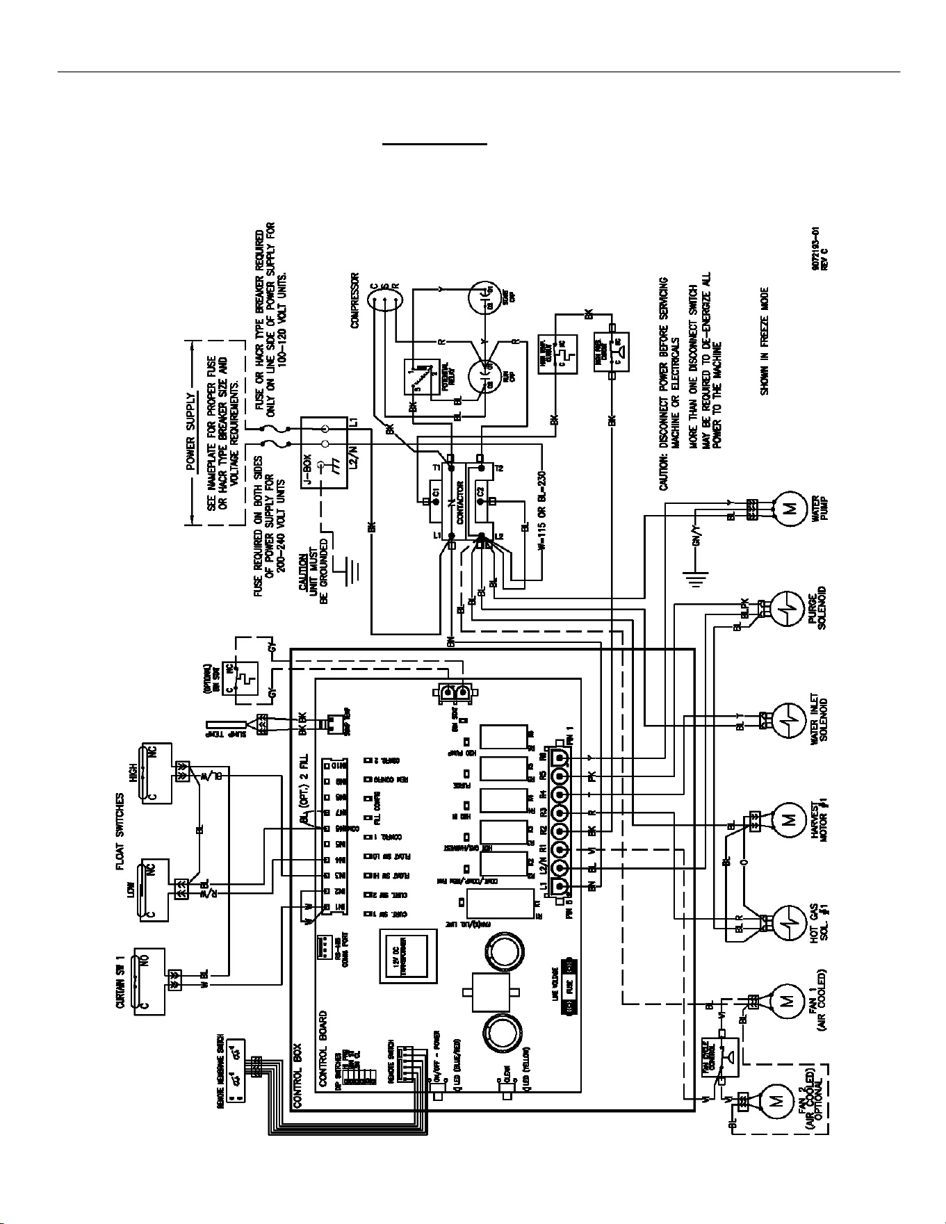
ELEVATION SERIES
WIRING DIAGRAM
71
Wiring Diagram
CIM 115V and 230V, 60Hz, SINGLE PHASE, SINGLE EVAPORATOR
AIR AND WATER COOLED UNITS
ELEVATION SERIES CIM CUBERS
TECHNICAL SPECIFICATIONS
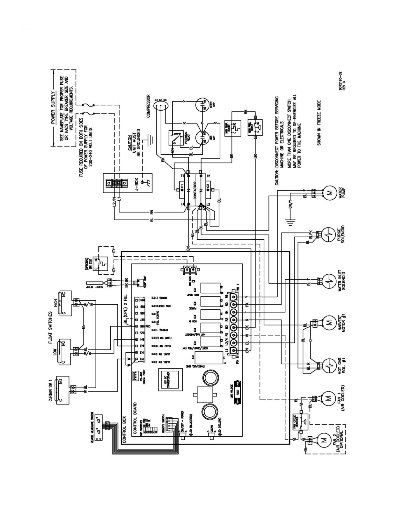
ELEVATION SERIES
WIRING DIAGRAM
72
CIM 220V ‐ 240V, 50Hz, SINGLE PHASE, SINGLE EVAPORATOR PLATE
AIR AND WATER COOLED UNITS
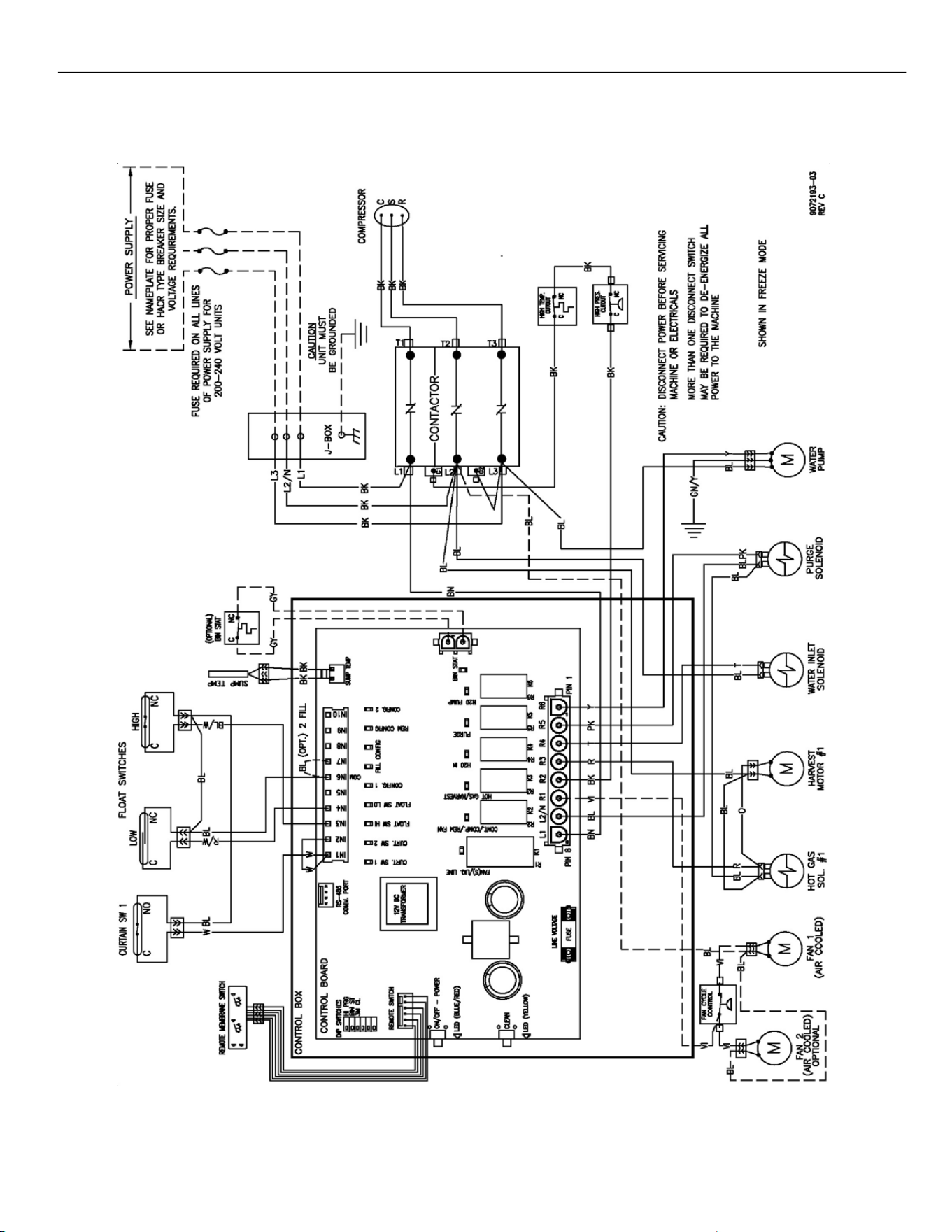
ELEVATION SERIES
WIRING DIAGRAM
73
CIM 115V and 230V, 60Hz, THREE PHASE, SINGLE EVAPORATOR
AIR AND WATER COOLED UNITS
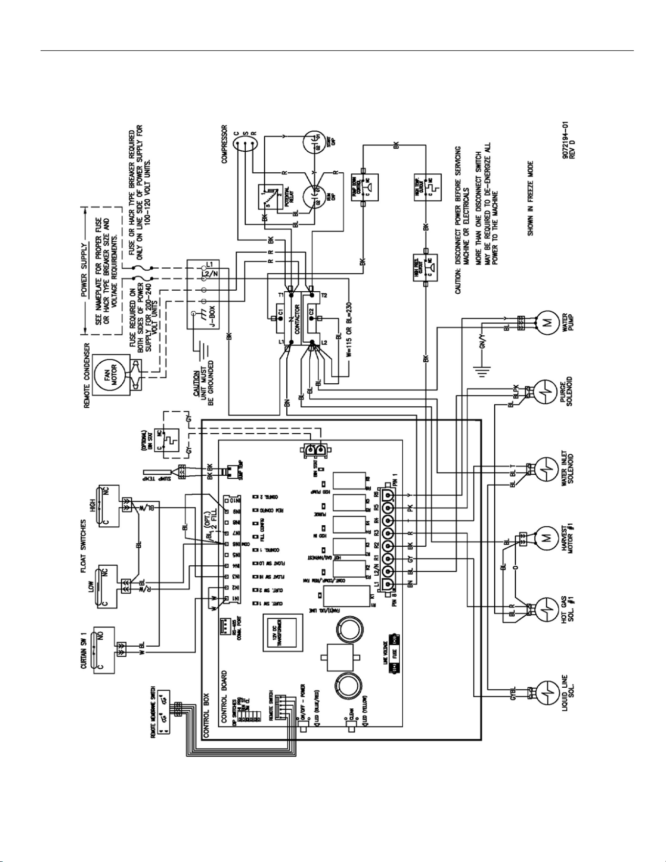
ELEVATION SERIES
WIRING DIAGRAM
74
CIM 115V and 230V, 60Hz, SINGLE PHASE, SINGLE EVAPORATOR PLATE
REMOTE COOLED UNITS
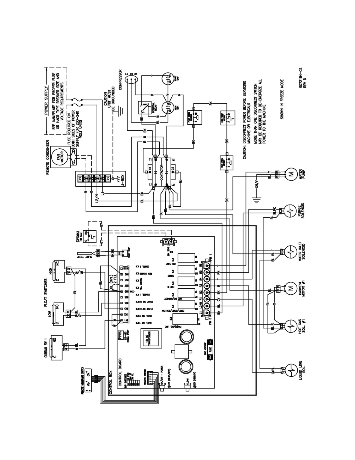
ELEVATION SERIES
WIRING DIAGRAM
75
CIM 220V ‐ 240V, 50Hz, SINGLE PHASE, SINGLE EVAPORATOR
REMOTE COOLED UINTS
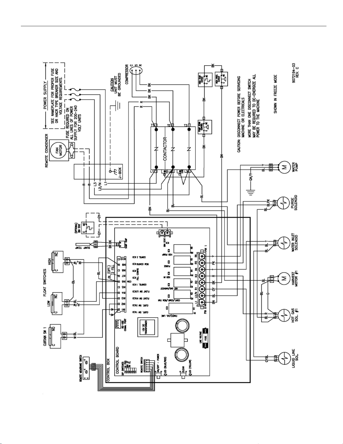
ELEVATION SERIES
WIRING DIAGRAM
76
CIM 230V, 60Hz, THREE PHASE, SINGLE EVAPORATOR PLATE
REMOTE COOLED UNITS
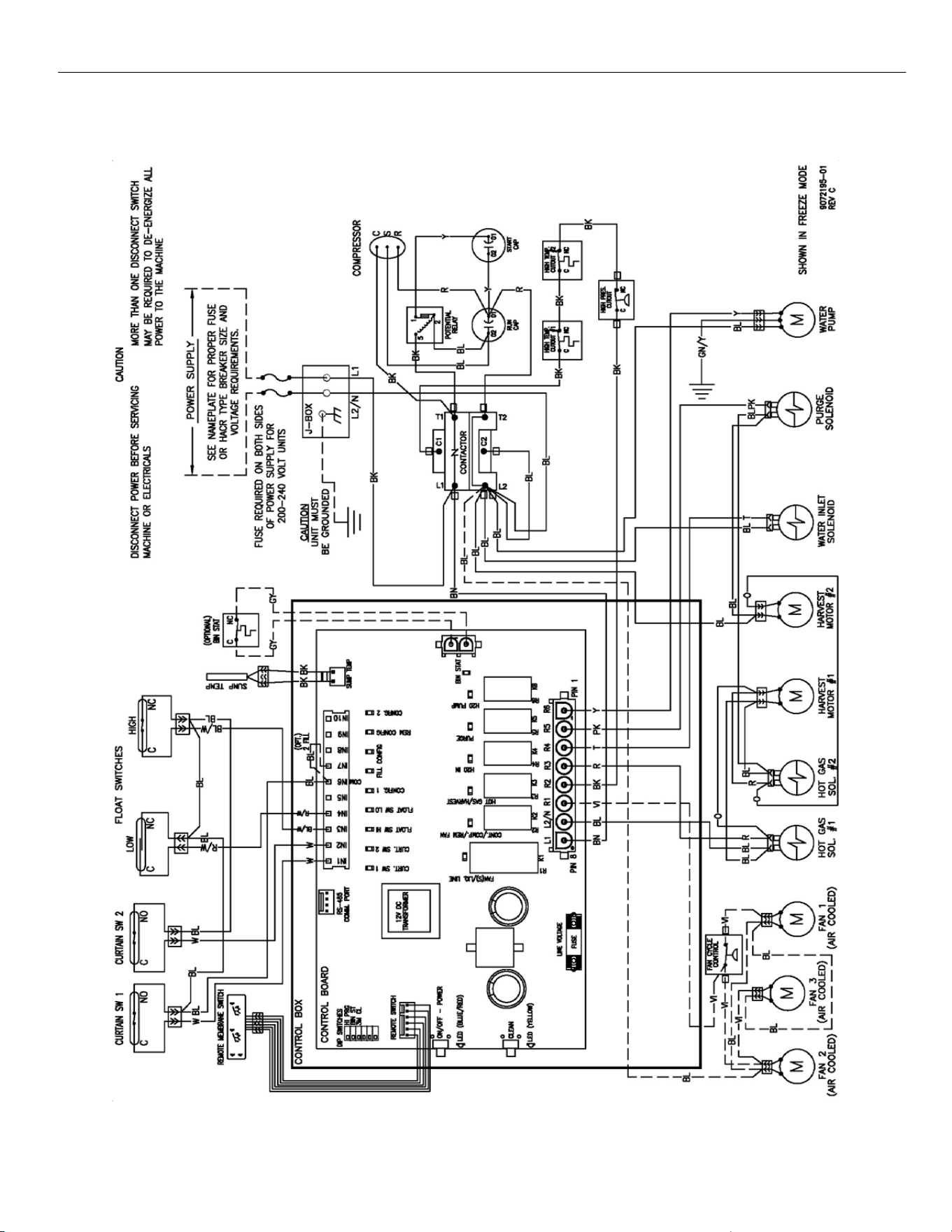
ELEVATION SERIES
WIRING DIAGRAM
77
CIM 230V, 60Hz, SINGLE PHASE, DUAL EVAPORATOR AIR AND
WATER COOLED UNITS
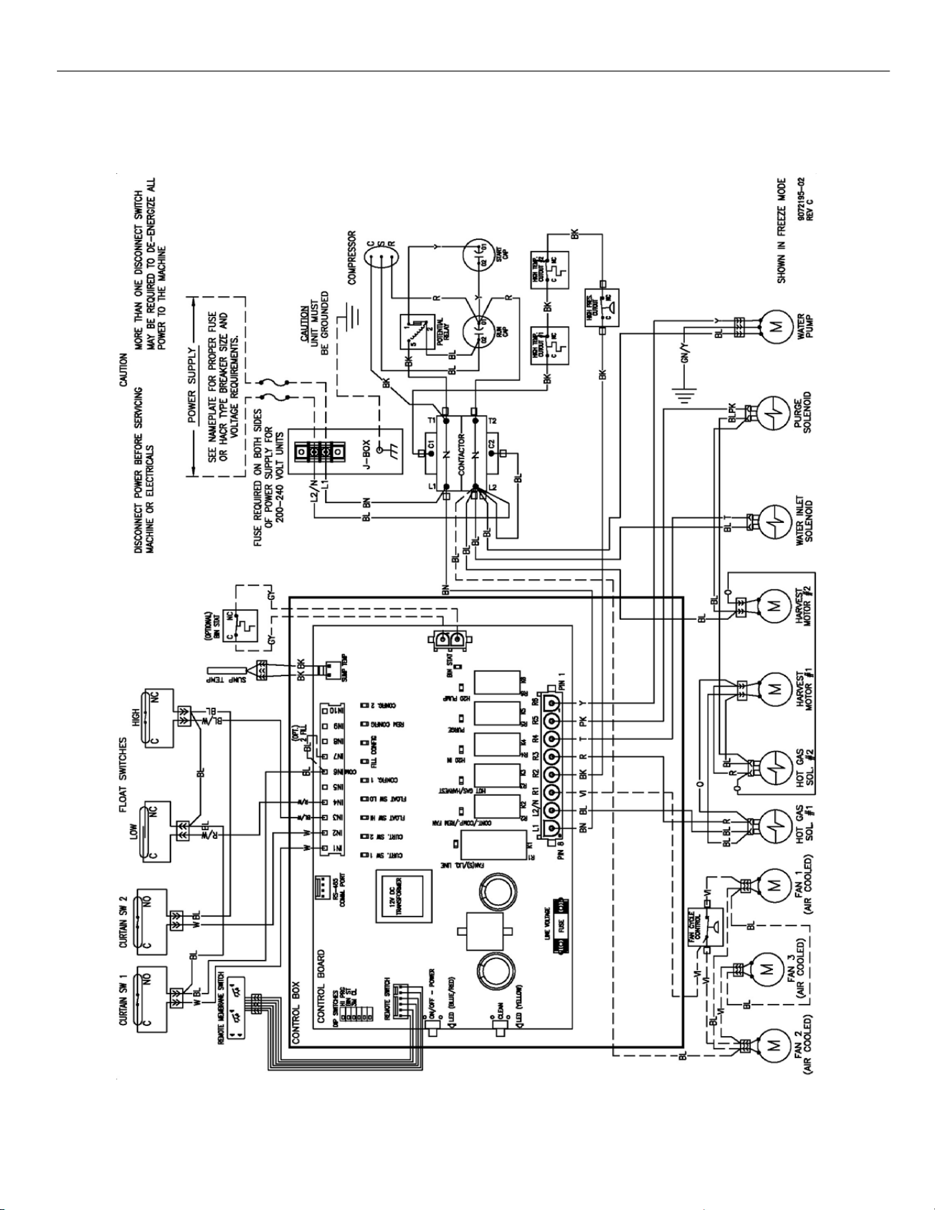
ELEVATION SERIES
WIRING DIAGRAM
78
CIM 220V ‐ 240V, 50Hz, SINGLE PHASE, DUAL EVAPORATOR
AIR AND WATER COOLED UNITS
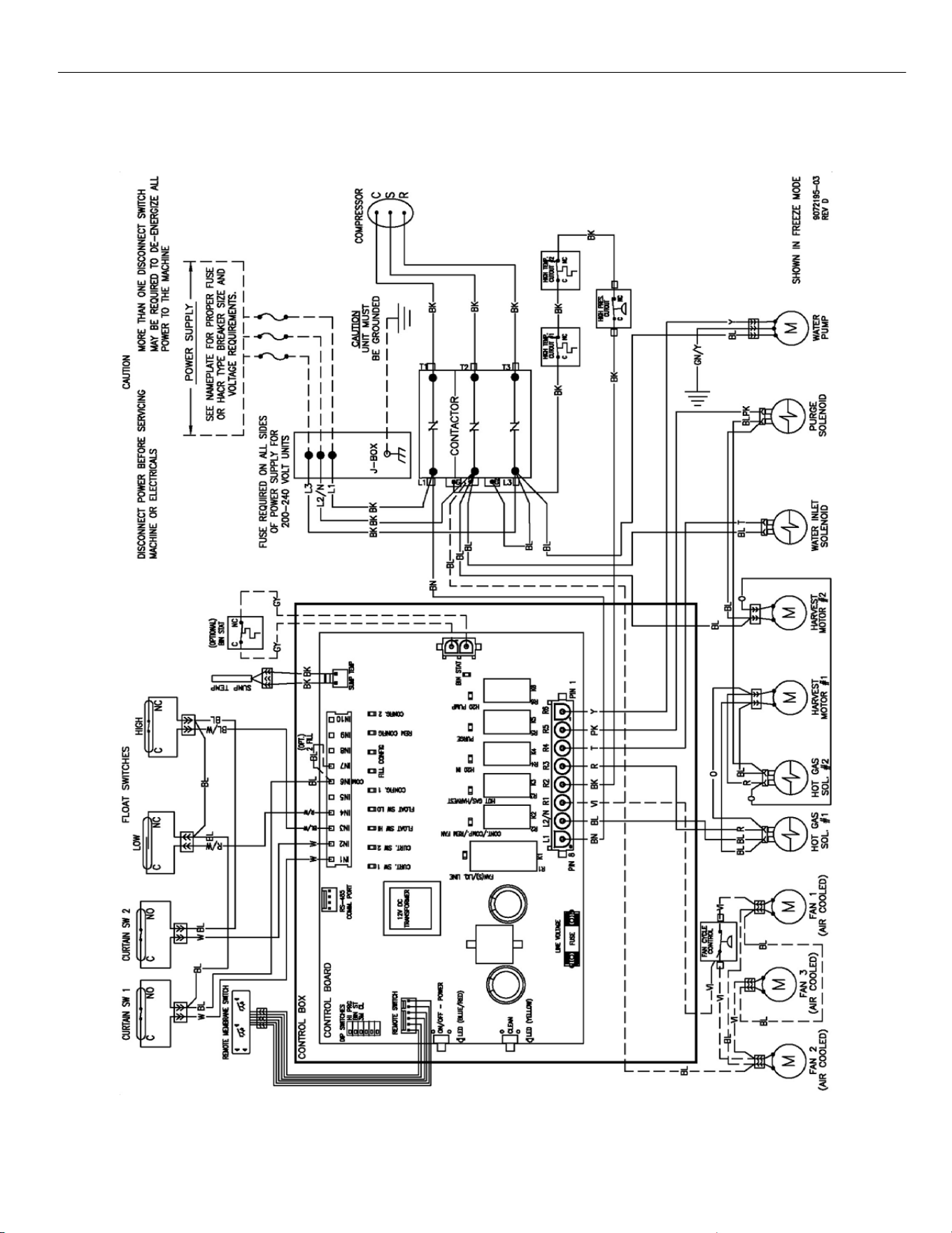
ELEVATION SERIES
WIRING DIAGRAM
79
CIM 230V, 60Hz, THREE PHASE, DUAL EVAPORATOR
AIR AND WATER COOLED UNITS
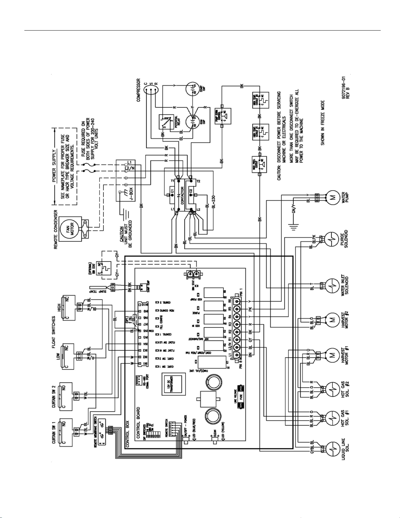
ELEVATION SERIES
WIRING DIAGRAM
80
CIM 115V and 230V, 60Hz, SINGLE PHASE, DUAL EVAPORATOR
REMOTE COOLED UNITS
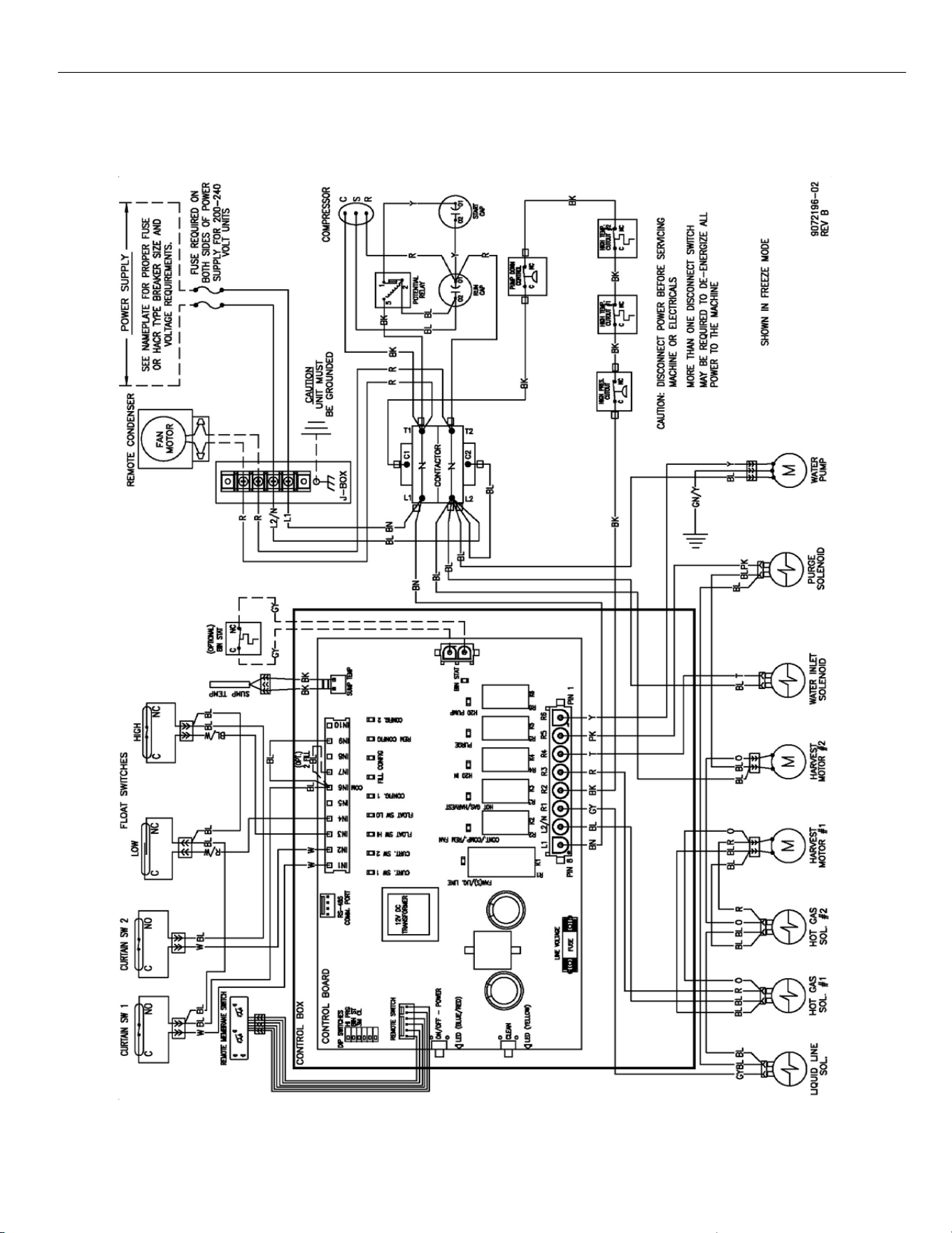
ELEVATION SERIES
WIRING DIAGRAM
81
CIM 220V ‐ 240V, 50Hz, SINGLE PHASE, DUAL EVAPORATOR
REMOTE COOLED UNITS
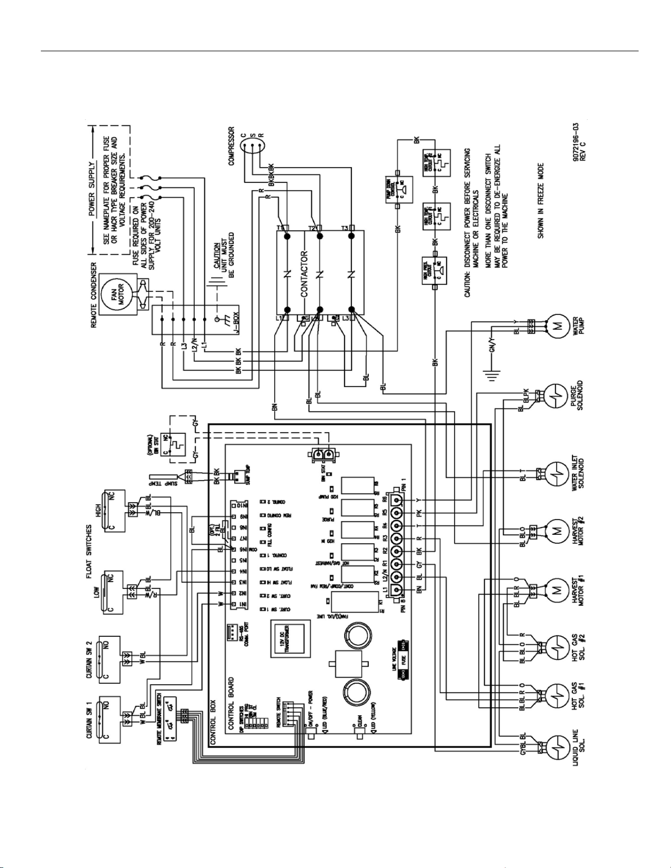
ELEVATION SERIES
WIRING DIAGRAM
82
CIM 230V, 60Hz, THREE PHASE, DUAL EVAPORATOR
REMOTE COOLED UNITS