ALL EASY PRO 3D INVERTER SERIES
SM_EP(GA)_R454B_3D INV_US_NA_2406
SERVICE MANUAL

Table of Contents
§. Safety Precautions
1. Precautions
2. Information servicing(For flammable materials)
§. Specifications
1. Model Reference
2. Pipe length and the Drop Height
3. Air Velocity and Temperature Distributions
4. Refrigerant Cycle Diagrams
5. Electrical Wiring Diagrams
§. Product Features
1. Display Function
2. Safety Features
3. Basic Features
§. Maintenance
1. First Time Installation Check
2. Refrigerant Recharge
3. Re-Installation
§. Troubleshooting
1. Safety Caution
2. General Troubleshooting
3. Outdoor Unit Point Check Function
4. Complain Record Form
5. Information Inquiry
6. Error Diagnosis and Troubleshooting Without Error Code
7. Quick Maintenance by Error Code
8. Troubleshooting by Error Code
9. Check Procedures
Appendix
i) Temperature Sensor Resistance Value Table for T1,T2,T3 and T4 (°C – K)
ii) Temperature Sensor Resistance Value Table for TP(for some units) (°C – K)
iii) Pressure On Service Port


Contents
1. Precautions .............................................................................................................2
2. Information servicing(For flammable materials) .................................................4
Safety Precautions
Safety Precautions 2
1. Precautions
To prevent personal injury, or property or unit damage,
adhere to all precautionary measures and instructions
outlined in this manual. Before servicing a unit, refer to this
service manual and its relevant sections.
Failure to adhere to all precautionary measures listed in this
section may result in personal injury, damage to the unit or
to property, or in extreme cases, death.
WARNING indicates a potentially hazardous
situation which if not avoided could result in serious
personal injury, or death.
CAUTION indicates a potentially hazardous situation
which if not avoided could result in minor or
moderate personal injury, or unit damage.
1.1 In case of Accidents or Emergency
WARNING
• If a gas leak is suspected, immediately turn off the
gas and ventilate the area if a gas leak is suspected
before turning the unit on.
• If strange sounds or smoke is detected from the unit,
turn the breaker off and disconnect the power supply
cable.
• If the unit comes into contact with liquid, contact an
authorized service center.
• If liquid from the batteries makes contact with skin or
clothing, immediately rinse or wash the area well with
clean water.
• Do not insert hands or other objects into the air inlet
or outlet while the unit is plugged in.
• Do not operate the unit with wet hands.
• Do not use a remote controller that has previously
been exposed to battery damage or battery leakage.
CAUTION
• Clean and ventilate the unit at regular intervals when
operating it near a stove or near similar devices.
• Do not use the unit during severe weather conditions.
If possible, remove the product from the window
before such occurrences.
1.2 Pre-Installation and Installation
WARNING
• Use this unit only on a dedicated circuit.
• Damage to the installation area could cause the unit
to fall, potentially resulting in personal injury, prop-
erty damage, or product failure.
• Only qualified personnel should disassemble, install,
remove, or repair the unit.
• Only a qualified electrician should perform electri-
cal work. For more information, contact your dealer,
seller, or an authorized service center.
CAUTION
• While unpacking be careful of sharp edges around
the unit as well as the edges of the fins on the con-
denser and evaporator.
1.3 Operation and Maintenance
WARNING
• Do not use defective or under-rated circuit breakers.
• Ensure the unit is properly grounded and that a
dedicated circuit and breaker are installed.
• Do not modify or extend the power cable. Ensure
the power cable is secure and not damaged during
operation.
• Do not unplug the power supply plug during
operation.
• Do not store or use flammable materials near the
unit.
• Do not open the inlet grill of the unit during
operation.
• Do not touch the electrostatic filter if the unit is
equipped with one.
• Do not block the inlet or outlet of air flow to the unit.
• Do not use harsh detergents, solvents, or similar items
to clean the unit. Use a soft cloth for cleaning.
• Do not touch the metal parts of the unit when
removing the air filter as they are very sharp.
• Do not step on or place anything on the unit or
outdoor units.
• Do not drink water drained from the unit
• Avoid direct skin contact with water drained from the
unit.
• Use a firm stool or step ladder according to
manufacturer procedures when cleaning or
maintaining the unit.
CAUTION
• Do not install or operate the unit for an extended
period of time in areas of high humidity or in an
environment directly exposing it to sea wind or salt
spray.
• Do not install the unit on a defective or damaged
installation stand, or in an unsecure location.
• Ensure the unit is installed at a level position
• Do not install the unit where noise or air discharge
created by the outdoor unit will negatively impact the
environment or nearby residences.
• Do not expose skin directly to the air discharged by
the unit for prolonged periods of time.
• Ensure the unit operates in areas water or other
liquids.
• Ensure the drain hose is installed correctly to ensure
proper water drainage.
• When lifting or transporting the unit, it is
recommended that two or more people are used for
this task.
• When the unit is not to be used for an extended time,
disconnect the power supply or turn off the breaker.
Safety Precautions 3
WARNING For Using Flammable Refrigerant
1. Installation (Space)
- That the installation of pipe-work shall be kept to a minimum.
- That pipe-work shall be protected from physical damage.
- Where refrigerant pipes shall be compliance with national gas
regulations.
- That mechanical connections shall be accessible for mainte-
nance purposes.
- In cases that require mechanical ventilation, ventilation open-
ings shall be kept clear of obstruction.
- When disposing of the product is used, be based on national
regulations, properly processed.
2. Servicing
- Any person who is involved with working on or breaking into a
refrigerant circuit should hold a current valid certificate from an
industry-accredited assessment authority, which authorises their
competence to handle refrigerants safely in accordance with an
industry recognised assessment specification.
3. Maintenance and repair requiring the assistance of other
skilled personnel shall be carried out under the supervision of the
person competent in the use of flammable refrigerants.
4. Do not use means to accelerate the defrosting process or to
clean, other than those recommended by the manufacturer.
5. The appliance shall be stored in a room without continuously
operating ignition sources (for example: open flames,an operat-
ing gas appliance or an operating electric heater).
6. Be more careful that foreign matter(oil, water,etc) does not
enter the piping. Also, when storing the piping, securely seal the
opening by pinching, taping, etc.
7. Do not pierce or burn.
8. Be aware that refrigerants may not contain an odour.
9. All working procedure that affects safety means shall only be
carried by competent persons.
10. Appliance shall be stored in a well -ventilated area where the
room size corresponds to the room area as specific for operation.
11. The appliance shall be stored so as to prevent mechanical
damage from occurring.
12. Joints shall be tested with detection equipment with a
capability of 5 g/year of refrigerant or better, with the equip-
ment in standstill and under operation or under a pressure of at
least these standstill or operation conditions after installation.
Detachable joints shall NOT be used in the indoor side of the unit
(brazed, welded joint could be used).
13. When a FLAMMABLE REFRIGERANT is used, the requirements
for installation space of appliance and /or ventilation require-
ments are determined according to
-- the mass charge amount(M) used in the appliance,
-- the installation location,
-- the type of ventilation of the location or of the appliance.
-- piping material, pipe routing, and installation shall include pro-
tection from physical damage in operation and service, and be in
compliance with national and local codes and standards, such as
ASHRAE 15, IAPMO Uniform Mechanical Code, ICC International
Mechanical Code, or CSA B52. All field joints shall be accessible
for inspection prior to being covered or enclosed.
-- that protection devices, piping, and fittings shall be protected
as far as possible against adverse environmental effects, for ex-
ample, the danger of water collecting and freezing in relief pipes
or the accumulation of dirt and debris;
-- that piping in refrigeration systems shall be so designed and
installed to minimize the likelihood of hydraulic shock damaging
the system;
-- that steel pipes and components shall be protected against
corrosion with a rustproof coating before applying any insulation;
-- that precautions shall be taken to avoid excessive vibration or
pulsation;
-- the minimum floor area of the room shall be mentioned in the
form of a table or a single figure without reference to a formula;
-- after completion of field piping for split systems, the field pipe-
work shall be pressure tested with an inert gas and then vacuum
tested prior to refrigerant charging, according to the following
requirements:
• The minimum test pressure for the low side of the system
shall be the low side design pressure and the minimum test
pressure for the high side of the system shall be the high
side design pressure, unless the high side of the system,
cannot be isolated from the low side of the system in which
case the entire system shall be pressure tested to the low
side design pressure.
• The test pressure after removal of pressure source shall be
maintained for at least 1h with no decrease of pressure
indicated by the test gauge, with test gauge resolution not
exceeding 5% of the test pressure.
• During the evacuation test, after achieving a vacuum level
specified in the manual or less, the refrigeration system
shall be isolated from the vacuum pump and the pressure
shall not rise above 1500 microns within 10 min. The
vacuum pressure level shall be specified in the manual, and
shall be the lessor of 500 microns or the value required for
compliance with national and local codes and standards,
which may vary between residential, commercial,and
industrial buildings.
-- field-made refrigerant joints indoors shall be tightness tested
according to the following requirements: The test method shall
have a sensitivity of 5 grams per year of refrigerant or better
under a pressure of at least 0,25 times the maximum allowable
pressure. No leak shall be detected.
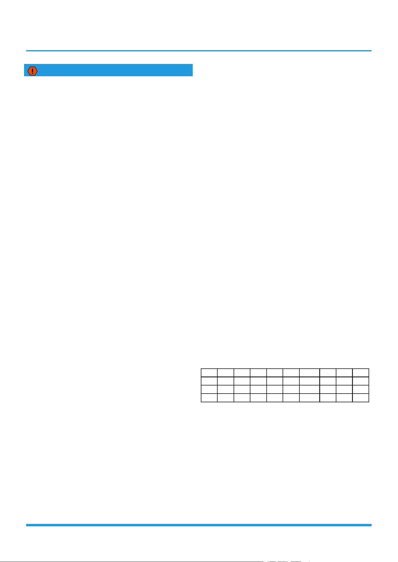
--correct the minimum room area of the space Amin by multiply-
ing by the altitude adjustment factor (AF) factor in the below
table based on for building site ground level altitude (Halt) in
meters.
Altitude Adjustment Factor
Halt 0 200 400 600 800 1000 1200 1400 1600
AF 1.00 1.00 1.00 1.00 1.02 1.05 1.07 1.10 1.12
Halt 1800 2000 2200 2400 2600 2800 3000 3200
AF 1.15 1.18 1.21 1.25 1.28 1.32 1.36 1.40
-- Warning: keep any required ventilation openings clear of
obstruction;
-- Any servicing shall be performed only as recommended by the
manufacturer
14. Qualification of workers
Any maintenance, service and repair operations must be
required qualification of the working personnel. Every working
procedure that affects safety means shall only be carried out
by competent persons that joined the training and achieved
competence should be documented by a certificate. The training
of these procedures is carried out by national training organisa-
tions or manufacturers that are accredited to teach the relevant
national competency standards that may be set in legislation. All
training shall follow the ANNEX HH requirements of UL 60335-2-
40 4rd Edition.

Safety Precautions 4
Examples for such working procedures are:
• breaking into the refrigerating circuit;
• opening of sealed components;
• opening of ventilated enclosures.
2. Information servicing(For
flammable materials)
2.1 Checks to the area
• Prior to beginning work on systems containing flammable
refrigerants, safety checks are necessary to ensure that the
risk of ignition is minimized. For repair to the refrigerating
system, the following precautions shall be complied with
prior to conducting work on the system.
2.2 Work procedure
• Work shall be undertaken under a controlled procedure so
as to minimise the risk of a flammable gas or vapour being
present while the work is being performed.
2.3 General work area
• All maintenance staff and others working in the local area
shall be instructed on the nature of work being carried out.
Work in confined spaces shall be avoided.
2.4 Checking for presence of refrigerant
• The area shall be checked with an appropriate refrigerant
detector prior to and during work, to ensure the technician
is aware of potentially flammable atmospheres.
• Ensure that the leak detection equipment being used is
suitable for use with flammable refrigerants, i.e. no sparking,
adequately sealed or intrinsically safe.
2.5 Presence of fire extinguisher
• If any hot work is to be conducted on the refrigeration
equipment or any associated parts, appropriate fire
extinguishing equipment shall be available to hand. Have
a dry powder or CO2 fire extinguisher adjacent to the
charging area.
2.6 No ignition sources
• No person carrying out work in relation to a refrigeration
system which involves exposing any pipe work that contains
or has contained flammable refrigerant shall use any sources
of ignition in such a manner that it may lead to the risk of
fire or explosion.
• All possible ignition sources, including cigarette smoking,
should be kept sufficiently far away from the site of
installation, repairing, removing and disposal, during which
flammable refrigerant can possibly be released to the
surrounding space.
• Prior to work taking place, the area around the equipment
is to be surveyed to make sure that there are no flammable
hazards or ignition risks.
• NO SMOKING signs shall be displayed.
2.7 Ventilated area
• Ensure that the area is in the open or that it is adequately
ventilated before breaking into the system or conducting any
hot work. A degree of ventilation shall continue during the
period that the work is carried out. The ventilation should
safely disperse any released refrigerant and preferably expel
it externally into the atmosphere.
2.8 Checks to the refrigeration equipment
• Where electrical components are being changed, they shall
be fit for the purpose and to the correct specification. At all
times the manufacturer’s maintenance and service guidelines
shall be followed. If in doubt consult the manufacturer’s
technical department for assistance. The following
checks shall be applied to installations using FLAMMABLE
REFRIGERANTS:
• the actual refrigerant charge is in accordance with the
room size within which the refrigerant containing parts
are installed;
• the ventilation machinery and outlets are operating
adequately and are not obstructed;
• if an indirect refrigerating circuit is being used, the
secondary circuits shall be checked for the presence of
refrigerant;
• marking to the equipment continues to be visible and
legible, marking and signs that are illegible shall be
corrected;
• refrigeration pipe or components are installed in a
position where they are unlikely to be exposed to any
substance which may corrode refrigerant containing
components, unless the components are constructed of
materials which are inherently resistant to being corroded
or are suitably protected against being so corroded.
2.9 Checks to electrical devices
• Repair and maintenance to electrical components shall
include initial safety checks and component inspection
procedures. If a fault exists that could compromise safety,
then no electrical supply shall be connected to the circuit
until it is satisfactorily dealt with. If the fault cannot be
corrected immediately but it is necessary to continue
operation, an adequate temporary solution shall be used.
This shall be reported to the owner of the equipment so all
parties are advised. Initial safety checks shall include:
• that capacitors are discharged: this shall be done in a safe
manner to avoid possibility of sparking;
• that there no live electrical components and wiring
are exposed while charging, recovering or purging the
system;
• that there is continuity of earth bonding.

Safety Precautions 5
2.10 Sealed electrical components shall be
replaced
• During repairs to sealed components, all electrical
supplies shall be disconnected from the equipment being
worked upon prior to any removal of sealed covers, etc.
If it is absolutely necessary to have an electrical supply to
equipment during servicing, then a permanently operating
form of leak detection shall be located at the most critical
point to warn of a potentially hazardous situation.
• Particular attention shall be paid to the following to ensure
that by working on electrical components, the casing is not
altered in such a way that the level of protection is affected.
This shall include damage to cables, excessive number of
connections, terminals not made to original specification,
damage to seals, incorrect fitting of glands, etc.
• Ensure that apparatus is mounted securely.
• Ensure that seals or sealing materials have not degraded
such that they no longer serve the purpose of preventing
the ingress of flammable atmospheres. Replacement
parts shall be in accordance with the manufacturer’s
specifications.
2.11 Intrinsically safe components must be
replaced
• Do not apply any permanent inductive or capacitance loads
to the circuit without ensuring that this will not exceed the
permissible voltage and current permitted for the equipment
in use. Intrinscially safe components are the only types that
can be worked on while live in the presence of a flammable
atmosphere. The test apparatus shall be at the correct
rating. Replace components only with parts specified by
the manufacturer. Other parts may result in the ignition of
refrigerant in the atmosphere from a leak.
NOTE: The use of silicon sealant may inhibit the effectiveness
of some types of leak detection equipment. Intrinsically safe
components do not have to be isolated prior to working on
them.
2.12 Cabling
• Check that cabling will not be subject to wear, corrosion,
excessive pressure, vibration, sharp edges or any other
adverse environmental effects. The check shall also take
into account the effects of aging or continual vibration from
sources such as compressors or fans.
2.13 Detection of flammable refrigerants
• Under no circumstances shall potential sources of ignition be
used in the searching for or detection of refrigerant leaks. A
halide torch (or any other detector using a naked flame) shall
not be used.
• The following leak detection methods are deemed
acceptable for refrigerant systems. Electronic leak detectors
may be used to detect refrigerant leaks but, in the case
of FLAMMABLE REFRIGERANTS, the sensitivity may not be
adequate, or may need re-calibration. (Detection equipment
shall be calibrated in a refrigerant-free area.) Ensure that
the detector is not a potential source of ignition and is
suitable for the refrigerant used. Leak detection equipment
shall be set at a percentage of the LFL of the refrigerant
and shall be calibrated to the refrigerant employed, and
the appropriate percentage of gas (25 % maximum) is
confirmed. Leak detection fluids are also suitable for use
with most refrigerants but the use of detergents containing
chlorine shall be avoided as the chlorine may react with the
refrigerant and corrode the copper pipe-work.
NOTE Examples of leak detection fluids are
- bubble method,
- fluorescent method agents.
• If a leak is suspected, all naked flames shall be removed/
extinguished.
• If a leakage of refrigerant is found which requires brazing,
all of the refrigerant shall be recovered from the system, or
isolated (by means of shut of valves) in a part of the system
remote from the leak. See the following instructions of
removal of refrigerant.
2.14 Removal and evacuation
• When breaking into the refrigerant circuit to make repairs
or for any other purpose, conventional procedures shall be
used. However, it is important that best practice is followed
since flammability is a consideration.
• The following procedure shall be adhered to:
• safely remove refrigerant following local and national
regulations;
• evacuate;
• purge the circuit with inert gas(optional for A2L);
• evacuate(optional for A2L);
• continuously flush or purge with inert gas when using
flame to open circuit; and open the circuit;
• The refrigerant charge shall be recovered into the correct
recovery cylinders if venting is not allowed by local and
national codes. For appliances containing flammable
refrigerants, the system shall be purged with oxygen-
free nitrogen to render the appliance safe for flammable
refrigerants. This process might need to be repeated several
times. Compressed air or oxygen shall not be used for
purging refrigerant systems.
• For appliances containing flammable refrigerants,
refrigerants purging shall be achieved by breaking the
vacuum in the system with oxygen-free nitrogen and
continuing to fill until the working pressure is achieved, then
venting to atmosphere, and finally pulling down to a vacuum
(optional for A2L). This process shall be repeated until no
refrigerant is within the system (optional for A2L). When the
final oxygen-free nitrogen charge is used, the system shall
be vented down to atmospheric pressure to enable work to
take place.
• The outlet for the vacuum pump shall not be close to any
potential ignition sources, and ventilation shall be available.

Safety Precautions 6
2.15 Charging procedures
• In addition to conventional charging procedures, the
following requirements shall be followed:
• Works shall be undertaken with appropriate tools only (In
case of uncertainty, please consult the manufacturer of
the tools for use with flammable refrigerants)
• Ensure that contamination of different refrigerants does
not occur when using charging equipment. Hoses or lines
shall be as short as possible to minimize the amount of
refrigerant contained in them.
• Cylinders shall be kept upright.
• Ensure that the refrigeration system is earthed prior to
charging the system with refrigerant.
• Label the system when charging is complete(if not
already). Extreme care shall be taken not to overfill the
refrigeration system.
• Prior to recharging the system it shall be pressure tested
with OFN. The system shall be leak tested on completion
of charging but prior to commissioning. A follow up
leak test shall be carried out prior to leaving the site.
2.16 Decommissioning
Before carrying out this procedure, it is essential that the
technician is completely familiar with the equipment and all its
detail. It is recommended good practice that all refrigerants are
recovered safely. Prior to the task being carried out, an oil and
refrigerant sample shall be taken in case analysis is required prior
to re-use of recovered refrigerant. It is essential that electrical
power is available before the task is commenced.
• Become familiar with the equipment and its operation.
• Isolate system electrically.
• Before attempting the procedure ensure that:
• mechanical handling equipment is available, if required,
for handling refrigerant cylinders;
• all personal protective equipment is available and being
used correctly;
• the recovery process is supervised at all times by a
competent person;
• recovery equipment and cylinders conform to the
appropriate standards.
• Pump down refrigerant system, if possible.
• If a vacuum is not possible, make a manifold so that
refrigerant can be removed from various parts of the system.
• Make sure that cylinder is situated on the scales before
recovery takes place.
• Start the recovery machine and operate in accordance with
manufacturer’s instructions.
• Do not overfill cylinders. (No more than 80 % volume liquid
charge).
• Do not exceed the maximum working pressure of the
cylinder, even temporarily.
• When the cylinders have been filled correctly and the process
completed, make sure that the cylinders and the equipment
are removed from site promptly and all isolation valves on
the equipment are closed off.
• Recovered refrigerant shall not be charged into another
refrigeration system unless it has been cleaned and checked.
2.17 Labelling
• Equipment shall be labelled stating that it has been de-
commissioned and emptied of refrigerant. The label shall be
dated and signed. For appliances containing FLAMMABLE
REFRIGERANTS, ensure that there are labels on the
equipment stating the equipment contains FLAMMABLE
REFRIGERANT.
2.18 Recovery
• When removing refrigerant from a system, either for
servicing or decommissioning,
• it is recommended good practice that all refrigerants are
removed safely.
• When transferring refrigerant into cylinders, ensure that
only appropriate refrigerant recovery cylinders are employed.
Ensure that the correct number of cylinders for holding the
total system charge is available. All cylinders to be used
are designated for the recovered refrigerant and labelled
for that refrigerant (i. e. special cylinders for the recovery
of refrigerant). Cylinders shall be complete with pressure-
relief valve and associated shut-of valves in good working
order. Empty recovery cylinders are evacuated and, if
possible,cooled before recovery occurs.
• The recovery equipment shall be in good working order
with a set of instructions concerning the equipment that
is at hand and shall be suitable for the recovery of the
flammable refrigerant. If in doubt the manufacturer should
be consulted. In addition, a set of calibrated weighing scales
shall be available and in good working order. Hoses shall be
complete with leak-free disconnect couplings and in good
condition.
• The recovered refrigerant shall be processed according
to local legislation in the correct recovery cylinder, and
the relevant waste transfer note arranged. Do not mix
refrigerants in recovery units and especially not in cylinders.
• If compressors or compressor oils are to be removed,
ensure that they have been evacuated to an acceptable
level to make certain that flammable refrigerant does not
remain within the lubricant. The compressor body shall not
be heated by an open flame or other ignition sources to
accelerate this process. When oil is drained from a system, it
shall be carried out safely.
2.19 Transportation, marking and storage
for units
1. Transport of equipment containing flammable refrigerants
Compliance with the transport regulations
2. Marking of equipment using signs

Safety Precautions 7
Compliance with local regulations
3. Disposal of equipment using flammable refrigerants
Compliance with national regulations
4. Storage of equipment/appliances
The storage of equipment should be in accordance with the
manufacturer’s instructions.
5. Storage of packed (unsold) equipment
Storage package protection should be constructed such that
mechanical damage to the equipment inside the package will
not cause a leak of the refrigerant charge. The maximum number
of pieces of equipment permitted to be stored together will be
determined by local regulations.

Contents
Specifications
1. Model Reference ........................................................................................... 2
2. Pipe Length and Drop Height ...................................................................... 3
3. Air Velocity and Temperature Distributions ............................................... 4
4. Refrigerant Cycle Diagrams ......................................................................... 20
5. Electrical Wiring Diagrams ........................................................................... 24
Specifications 2
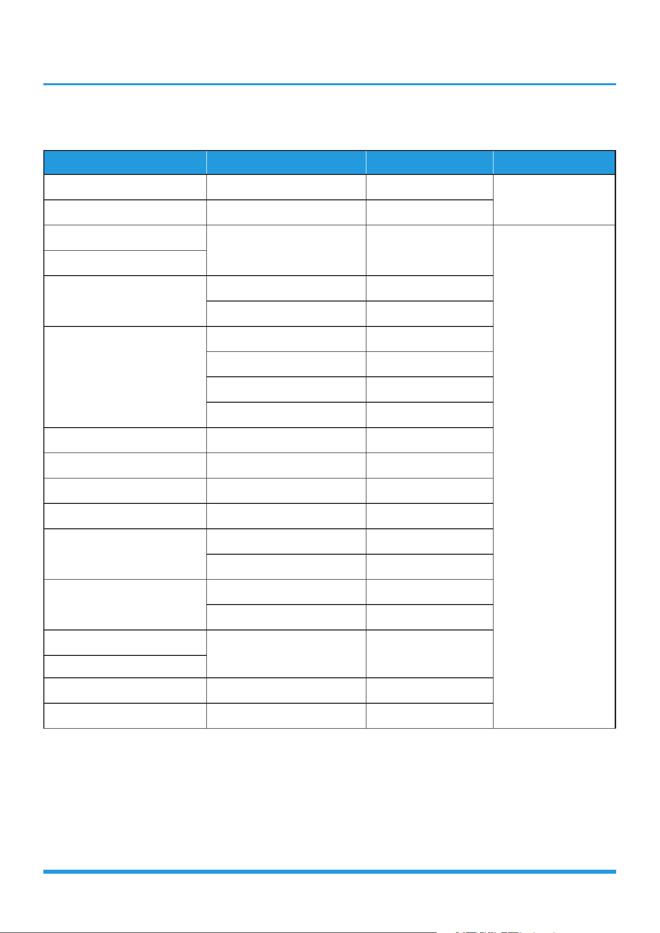
1. Model Reference
Refer to the following table to determine the specific indoor and outdoor unit model.
Indoor Unit Model Outdoor Unit Model Capacity (Btu/h) Power Supply
MSEPB-09HRFN10-B1 MOX230-09HFN10-B1 9k Energy Star Series
115V~, 60Hz, 1Phase
MSEPB-12HRFN10-B1 MOX230-12HFN10-B1 12k Energy Star Series
MSEPBM-12HRFN10-M1
MOX230-06HFN10-M1X 6k Hyper Heat Series
208/230V~, 60Hz,
1Phase
MSEPB-06HRFN10-M1
MSEPB-09HRFN10-M1
MOX230-09HFN10-M1 9k Energy Star Series
MOX330-09HFN10-M1X 9k Hyper Heat Series
MSEPBM-12HRFN10-M1
MOX230-09HFN10-M1 9k Energy Star Series
MOX330-09HFN10-M1X 9k Hyper Heat Series
MOX230-12HFN10-M1 12k Energy Star Series
MOX330-12HFN10-M1X 12k Hyper Heat Series
MSEPC-06HRFN1-M1H MOX430-06HFN1-M1H 6k High Tier Series
MSEPC-09HRFN1-M1H MOX430-09HFN1-M1H 9k High Tier Series
MSEPC-12HRFN10-M1H MOX430-12HFN10-M1H 12k High Tier Series
MSEPD-18HRFN10-M1H MOD30-18HFN10-M1H 18k High Tier Series
MSEPC-18HRFN10-M1
MOX430-18HFN10-M1X 18k Hyper Heat Series
MOX430-18HFN10-M1 18k Energy Star Series
MSEPD-24HRFN10-M1
MOD30-24HFN10-M1X 24k Hyper Heat Series
MOD30-24HFN10-M1 24k Energy Star Series
MSEPDM-36HRFN10-M1E
MOD30-30HFN10-M1E 30k Entry Tier Series
MSEPD-30HRFN10-M1
MSEPD-33HRFN10-M1 MOD30-33HFN10-M1X 33k Hyper Heat Series
MSEPDM-36HRFN10-M1E MOD30-36HFN10-M1E 36k Entry Tier Series
Specifications 3
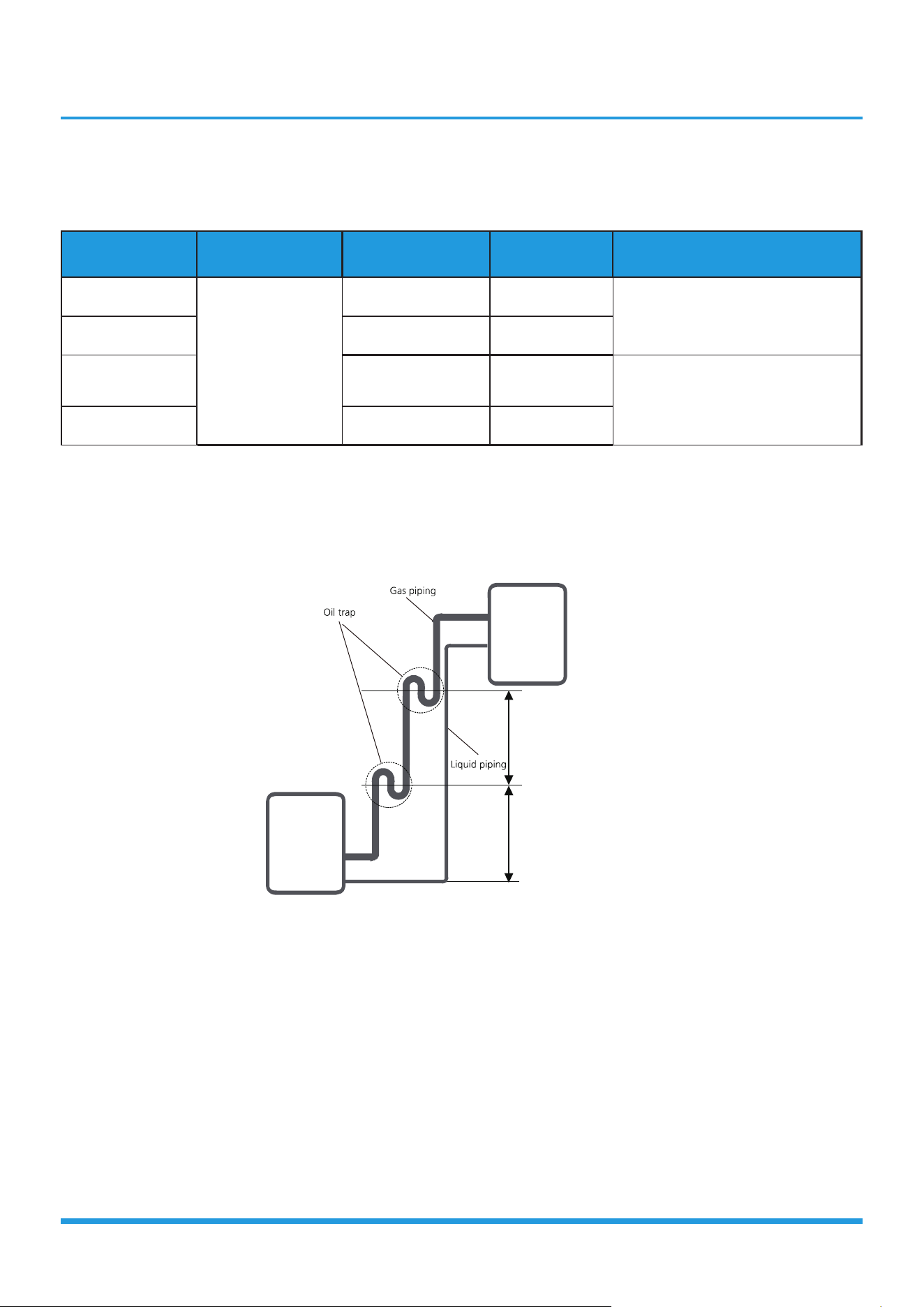
2. Pipe Length and Drop Height
The length and elevation of connection pipe are shown in the table below. if the pipe length exceeds max pipe length,
additional refrigerant should be charged to ensure nominal cooling/heating capacity.
Capacity(Btu/h) Standard Length Max Pipe Length Max Elevation Additional Refrigerant
<15k
7.5m (24.6ft)
25m (82.0ft) 15m (49.2ft)
15g/m (0.16oz/ft)
18k 30m (98.4ft) 20m (65.6ft)
18k High
Tier Series/
24k/30k/33k
50m (164ft) 25m (82ft)
30g/m (0.32oz/ft)
36k 65m (213ft) 30m (98.4ft)
If oil flows back into the outdoor unit’s compressor, this might cause liquid compression or deterioration of oil return. Oil
traps in the rising gas pipe can prevent this.
-An oil trap should be installed every 6m(20ft) of vertical suction line riser (<36000Btu/h unit).
-An oil trap should be installed every 10m(32.8ft) of vertical suction line riser (≥36000Btu/h unit).
10m/32.8ft (≥36000Btu/h unit)
6m/20ft (<36000Btu/h unit)
10m/32.8ft (≥36000Btu/h unit)
6m/20ft (<36000Btu/h unit)
Indoor unit/
Outdoor unit
Indoor unit/
Outdoor unit
Specifications 4
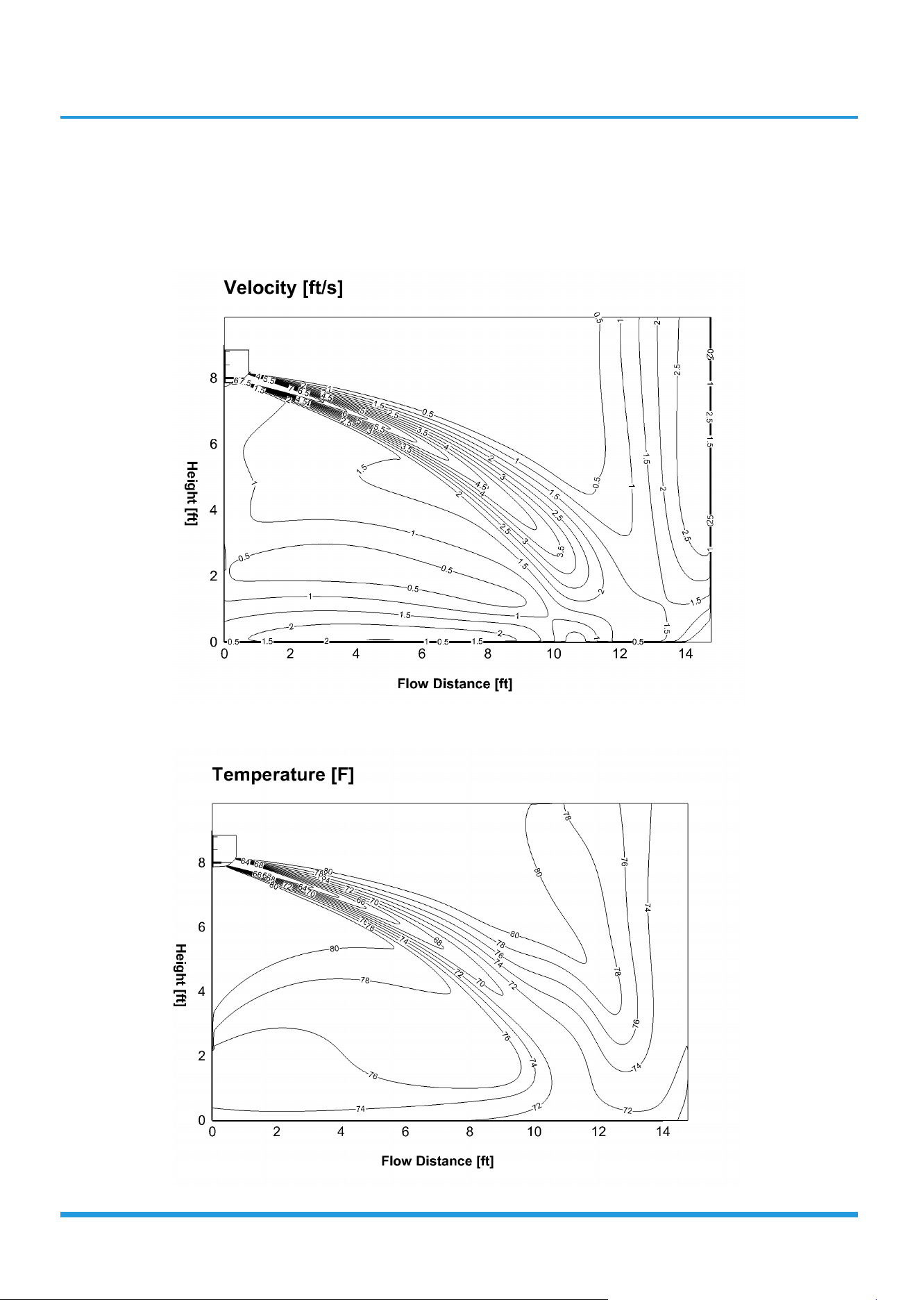
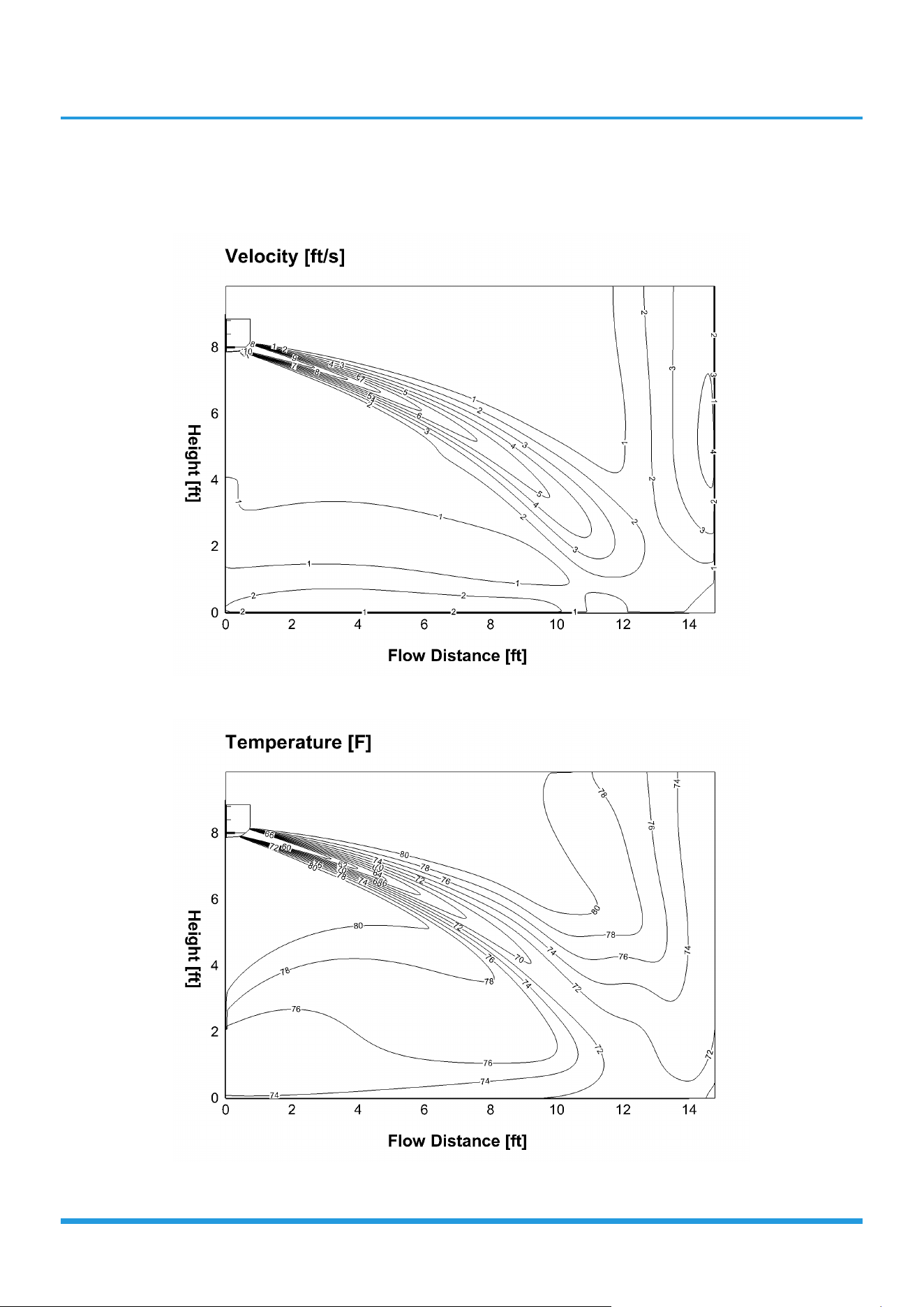
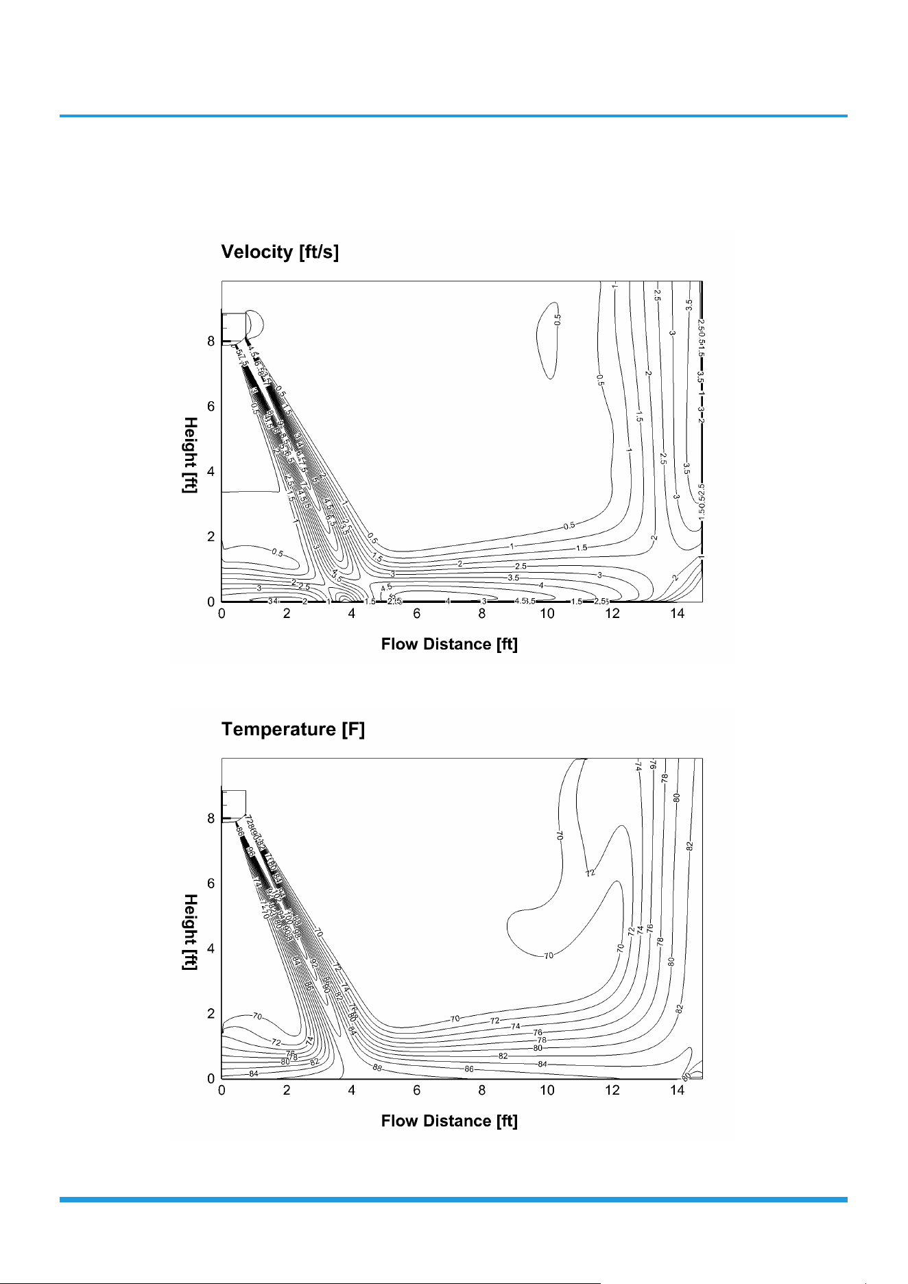
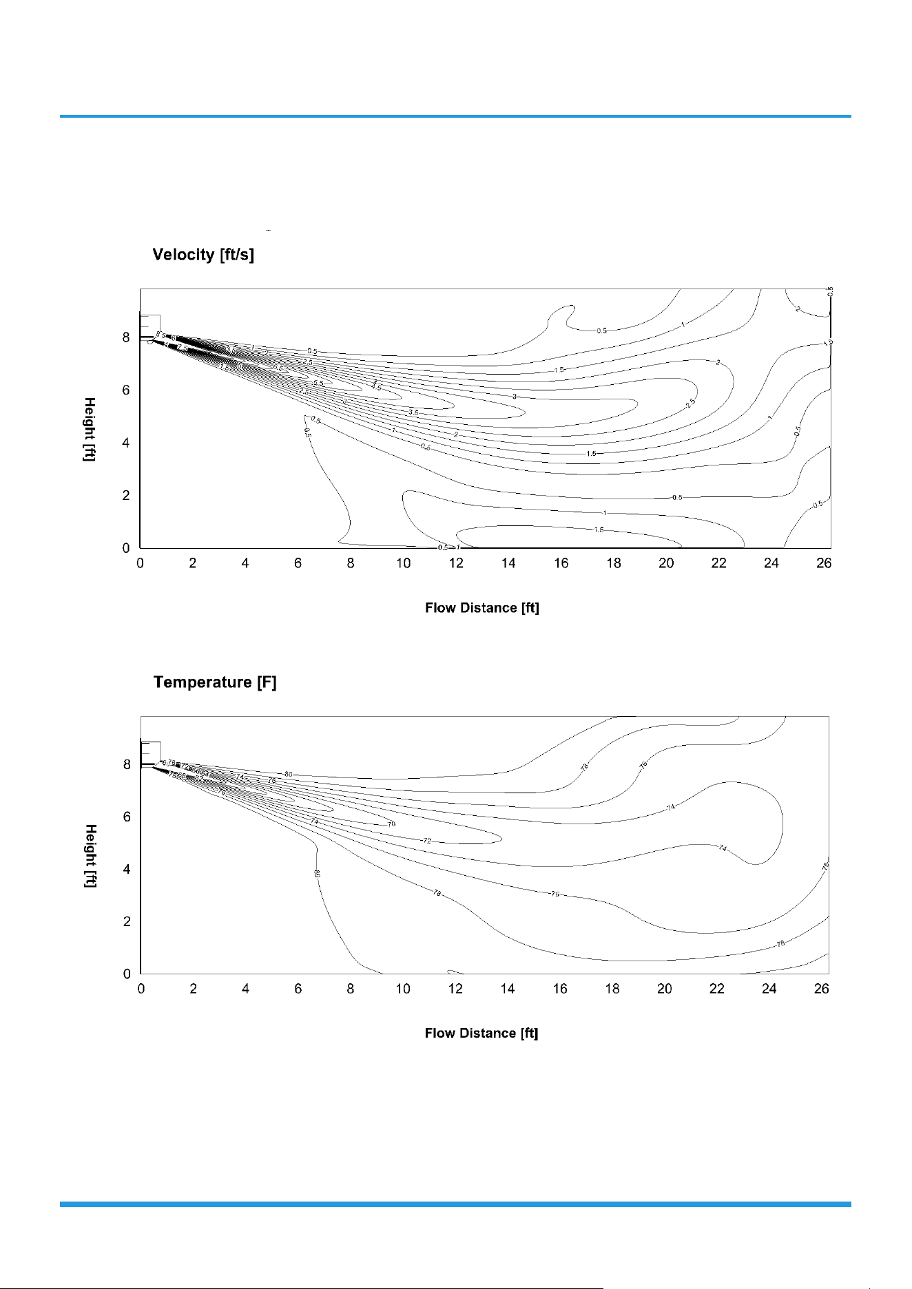
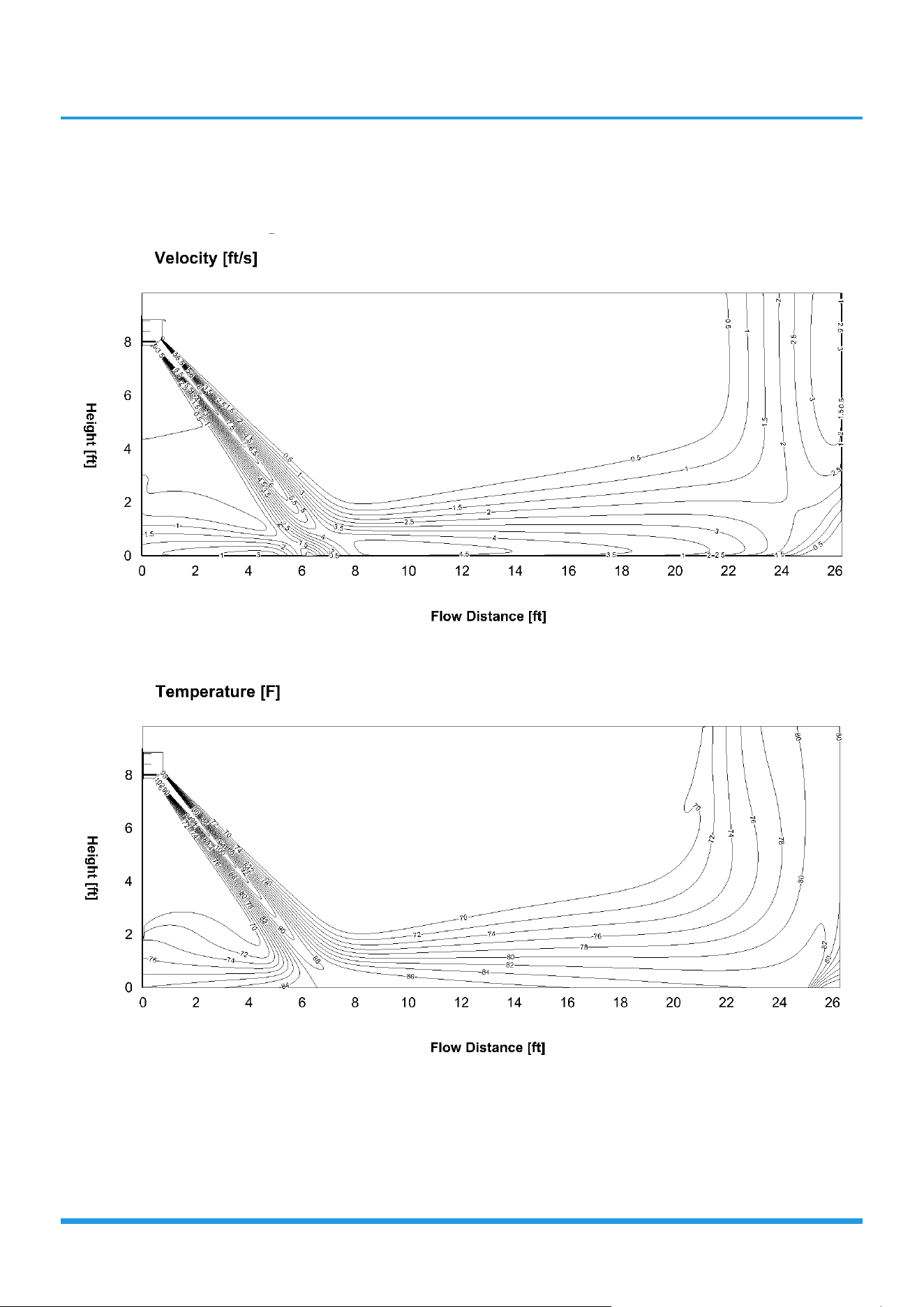
3. Air Velocity and Temperature Distributions
6k-Cooling(ID: 27
°C
/80.6
°F
, OD: 35
°C
/95
°F
)
Discharge Angle 60°
Airflow velocity dis
tributions
Temperature dis
tributions
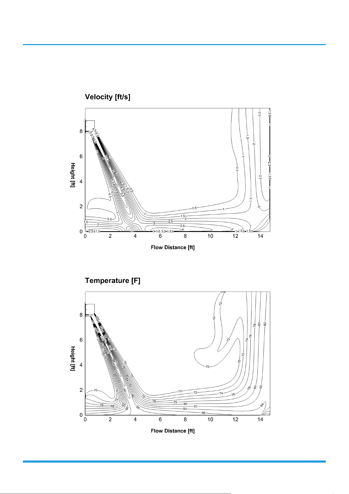
Specifications 5
6k-Heating(ID: 20
°C
/68
°F
, OD: 7
°C
/44.6
°F
)
Discharge Angle 110°
Airflow velocity dis
tributions
Temperature dis
tributions
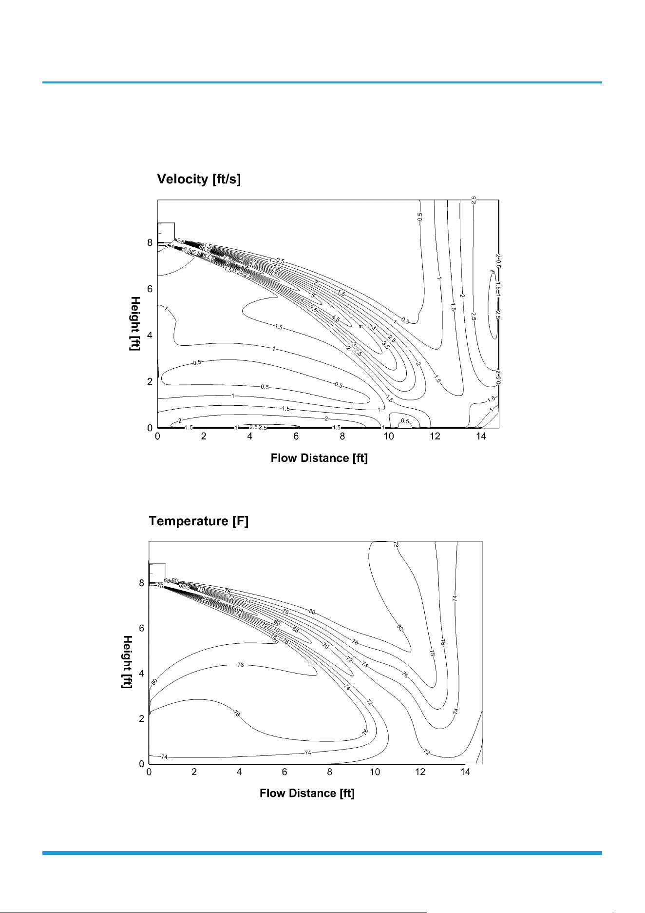
Specifications 6
9k-Cooling(ID: 27
°C
/80.6
°F
, OD: 35
°C
/95
°F
)
Discharge Angle 60°
Airflow velocity dis
tributions
Temperature dis
tributions
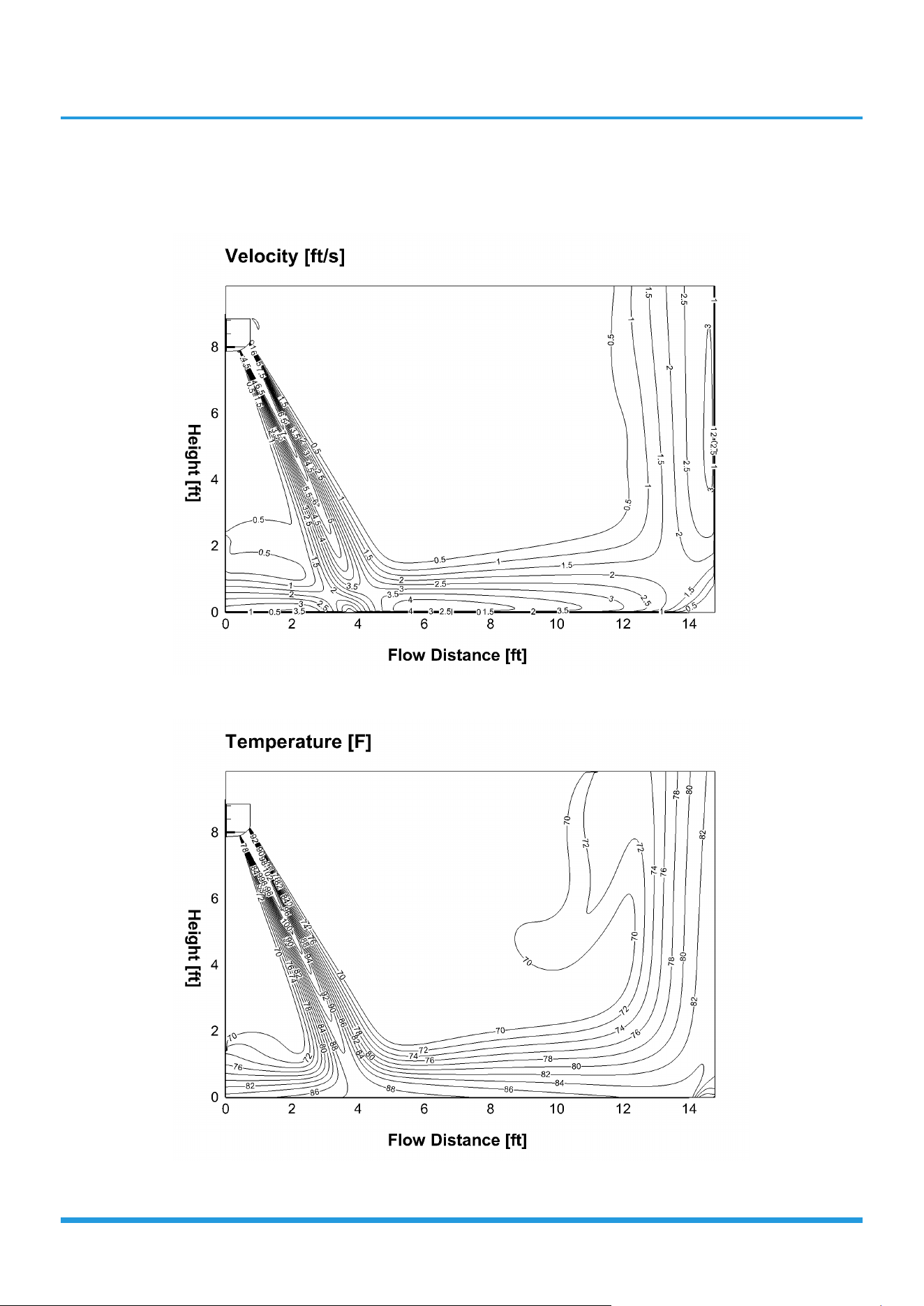
Specifications 7
9k-Heating(ID: 20
°C
/68
°F
, OD: 7
°C
/44.6
°F
)
Discharge Angle 110°
Airflow velocity dis
tributions
Temperature dis
tributions
Specifications 8
12k-Cooling(ID: 27
°C
/80.6
°F
, OD: 35
°C
/95
°F
)
Discharge Angle 60°
Airflow velocity dis
tributions
Temperature dis
tributions
Specifications 9
12k-Heating(ID: 20
°C
/68
°F
, OD: 7
°C
/44.6
°F
)
Discharge Angle 110°
Airflow velocity dis
tributions
Temperature dis
tributions
Specifications 10
18k-Cooling(ID: 27
°C
/80.6
°F
, OD: 35
°C
/95
°F
)
Discharge Angle 60°
Airflow velocity dis
tributions
Temperature dis
tributions
Specifications 11
18k-Heating(ID: 20
°C
/68
°F
, OD: 7
°C
/44.6
°F
)
Discharge Angle 95°
Airflow velocity dis
tributions
Temperature dis
tributions
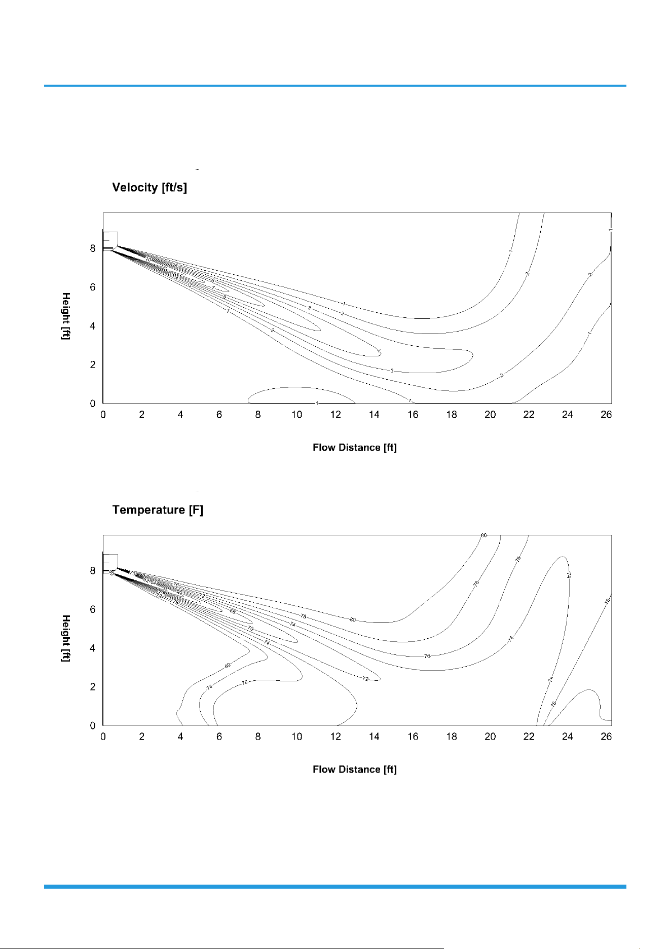
Specifications 12
24k-Cooling(ID: 27
°C
/80.6
°F
, OD: 35
°C
/95
°F
)
Discharge Angle 65°
Airflow velocity dis
tributions
Temperature dis
tributions
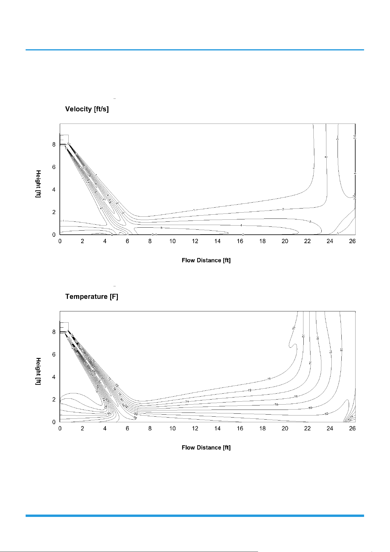
Specifications 13
24k-Heating(ID: 20
°C
/68
°F
, OD: 7
°C
/44.6
°F
)
Discharge Angle 100°
Airflow velocity dis
tributions
Temperature dis
tributions
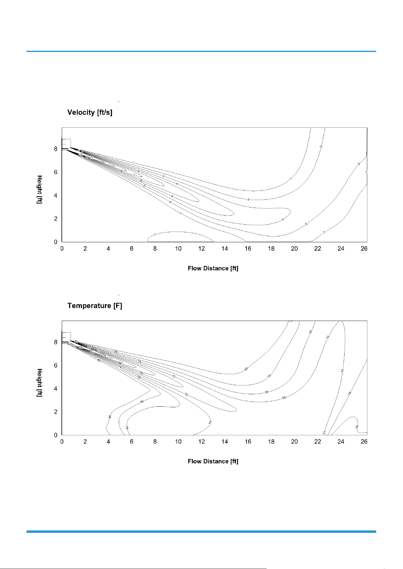
Specifications 14
30k-Cooling(ID: 27
°C
/80.6
°F
, OD: 35
°C
/95
°F
)
Discharge Angle 65°
Airflow velocity dis
tributions
Temperature dis
tributions
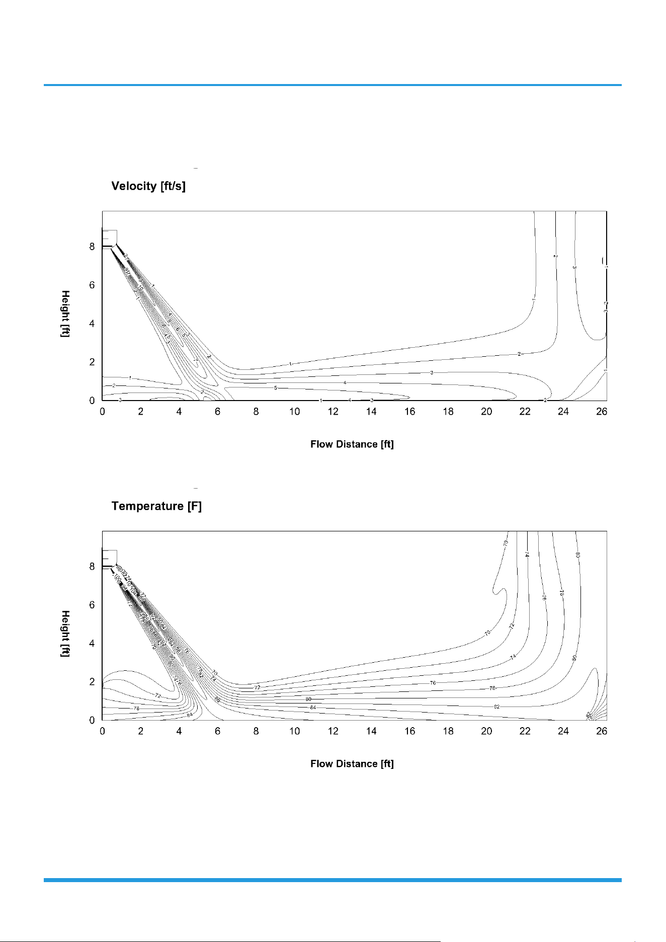
Specifications 15
30k-Heating(ID: 20
°C
/68
°F
, OD: 7
°C
/44.6
°F
)
Discharge Angle 100°
Airflow velocity dis
tributions
Temperature dis
tributions
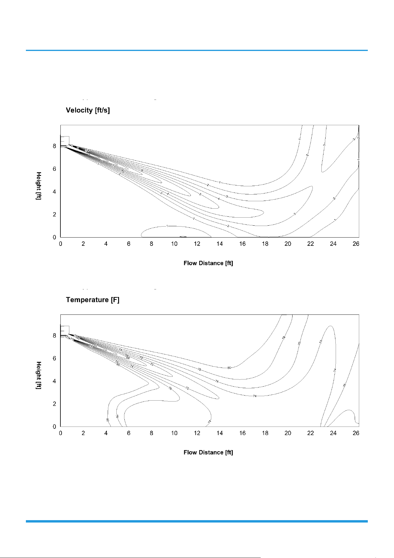
Specifications 16
33k-Cooling(ID: 27
°C
/80.6
°F
, OD: 35
°C
/95
°F
)
Discharge Angle 65°
Airflow velocity dis
tributions
Temperature dis
tributions
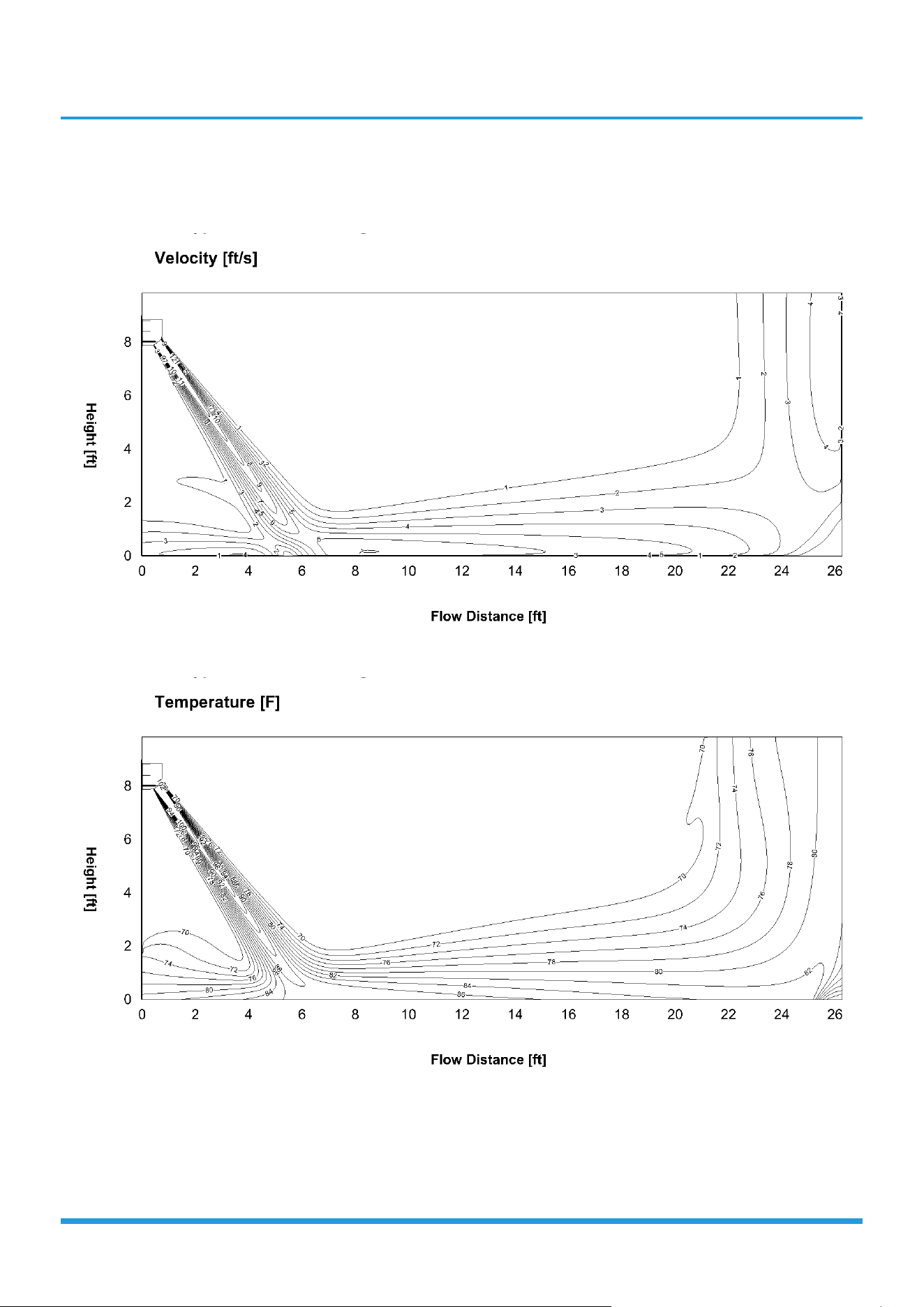
Specifications 17
33k-Heating(ID: 20
°C
/68
°F
, OD: 7
°C
/44.6
°F
)
Discharge Angle 100°
Airflow velocity dis
tributions
Temperature dis
tributions
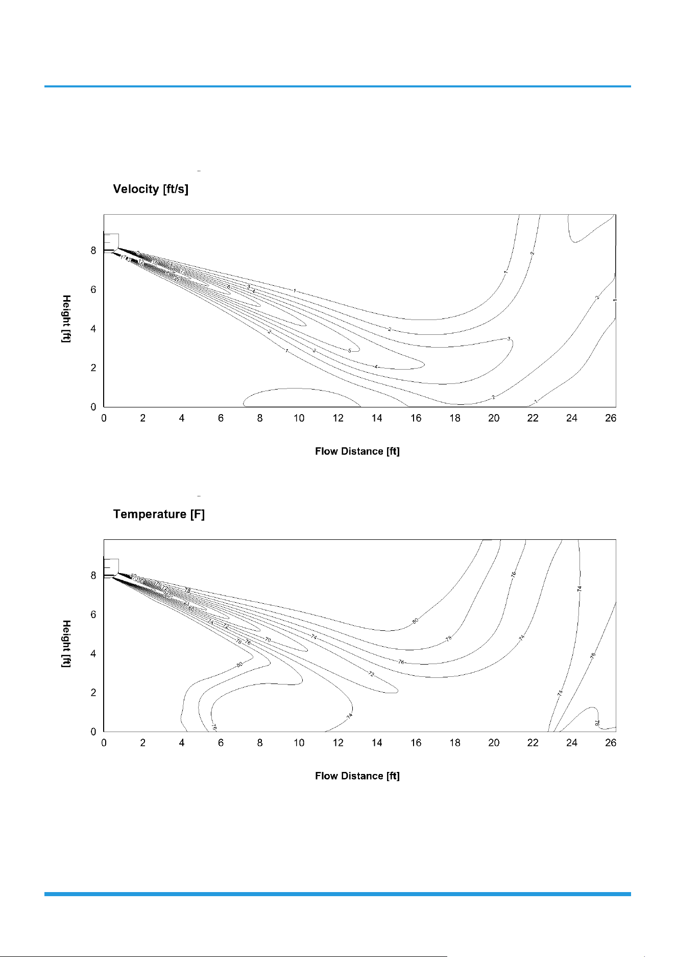
Specifications 18
36k-Cooling(ID: 27
°C
/80.6
°F
, OD: 35
°C
/95
°F
)
Discharge Angle 65°
Airflow velocity dis
tributions
Temperature dis
tributions
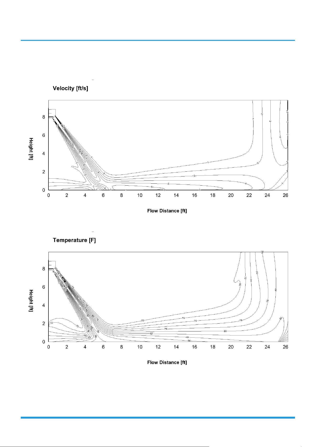
Specifications 19
36k-Heating(ID: 20
°C
/68
°F
, OD: 7
°C
/44.6
°F
)
Discharge Angle 100°
Airflow velocity dis
tributions
Temperature dis
tributions
Specifications 20
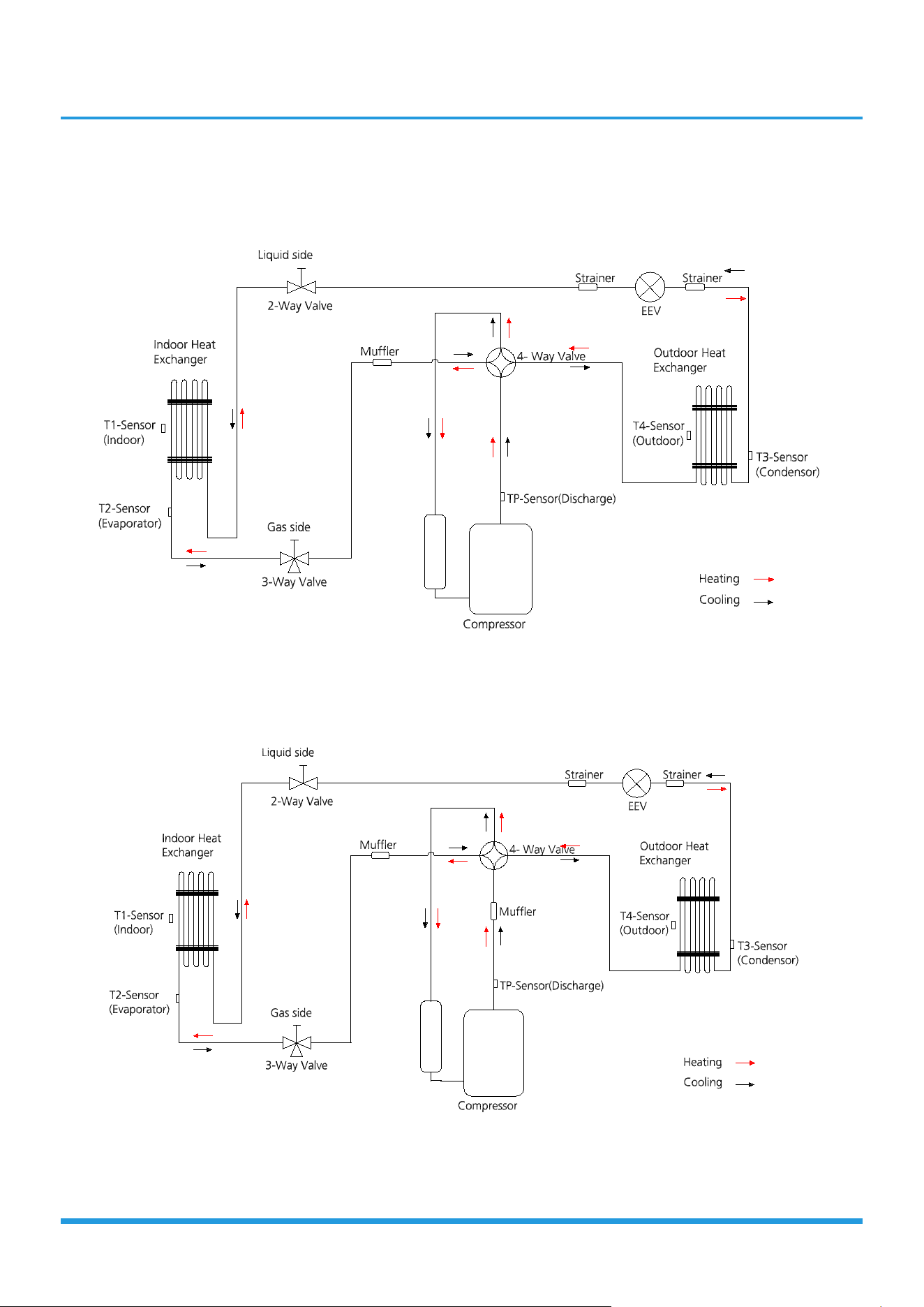
4. Refrigerant Cycle Diagrams
MOX230-09HFN10-B1, MOX230-12HFN10-B1, MOX230-06HFN10-M1X, MOX330-09HFN10-M1X,
MOX230-09HFN10-M1, MOX230-12HFN10-M1,MOX330-12HFN10-M1X
MOX430-06HFN1-M1H, MOX430-09HFN1-M1H, MOX430-12HFN10-M1H
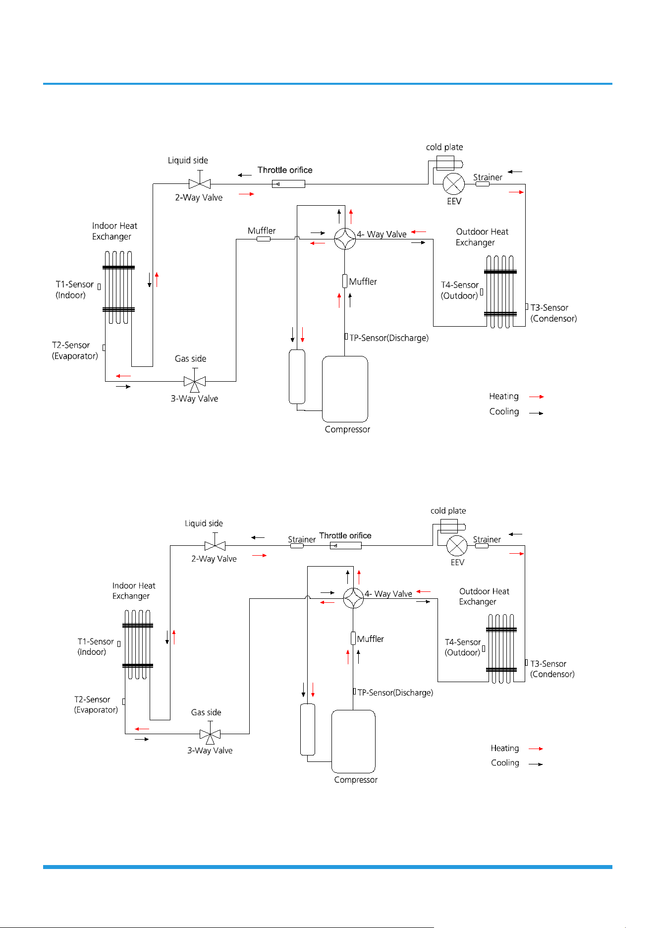
Specifications 21
MOX430-18HFN10-M1X, MOX430-18HFN10-M1
MOD30-18HFN10-M1H, MOD30-24HFN10-M1X, MOD30-30HFN10-M1E
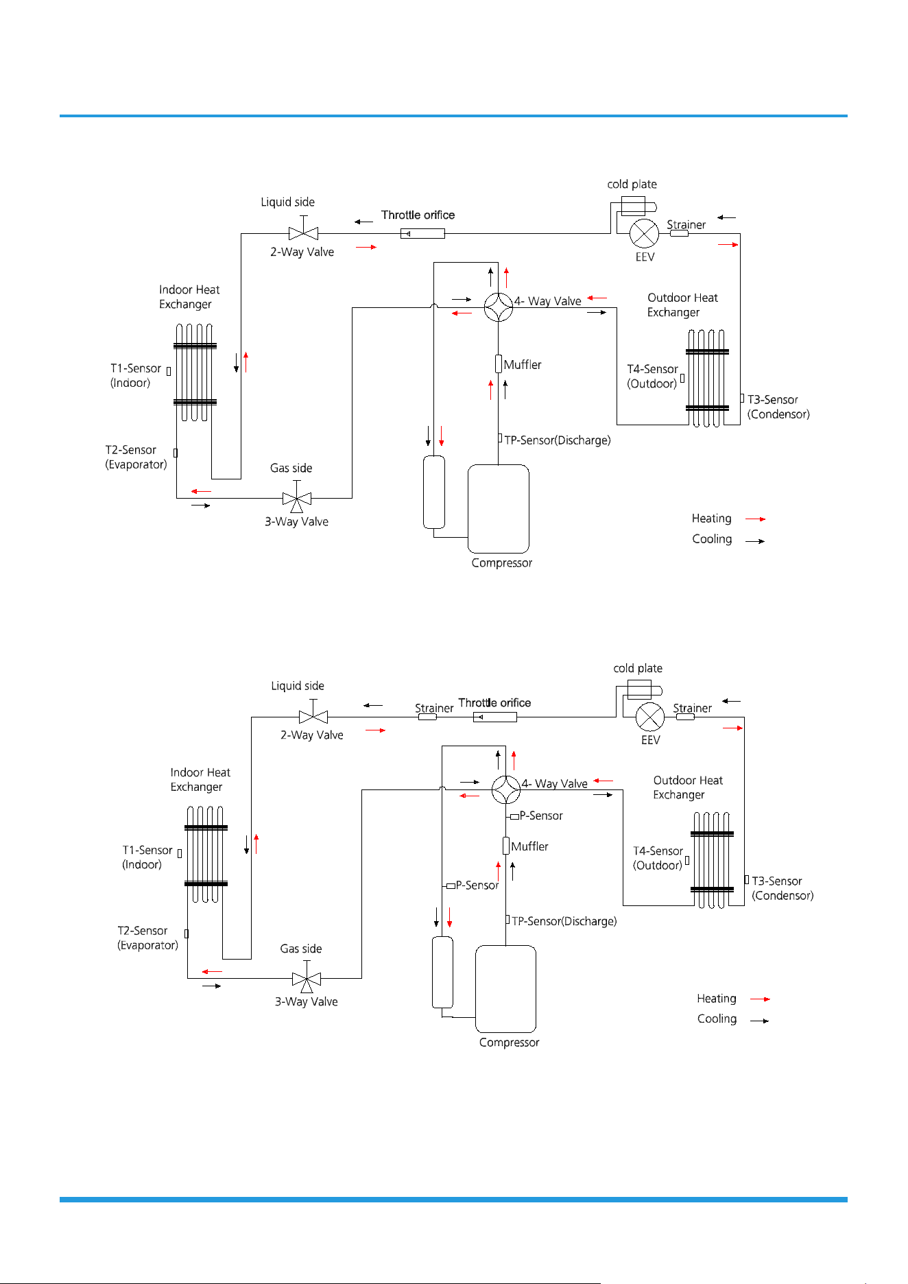
Specifications 22
MOD30-24HFN10-M1
MOD30-33HFN10-M1X
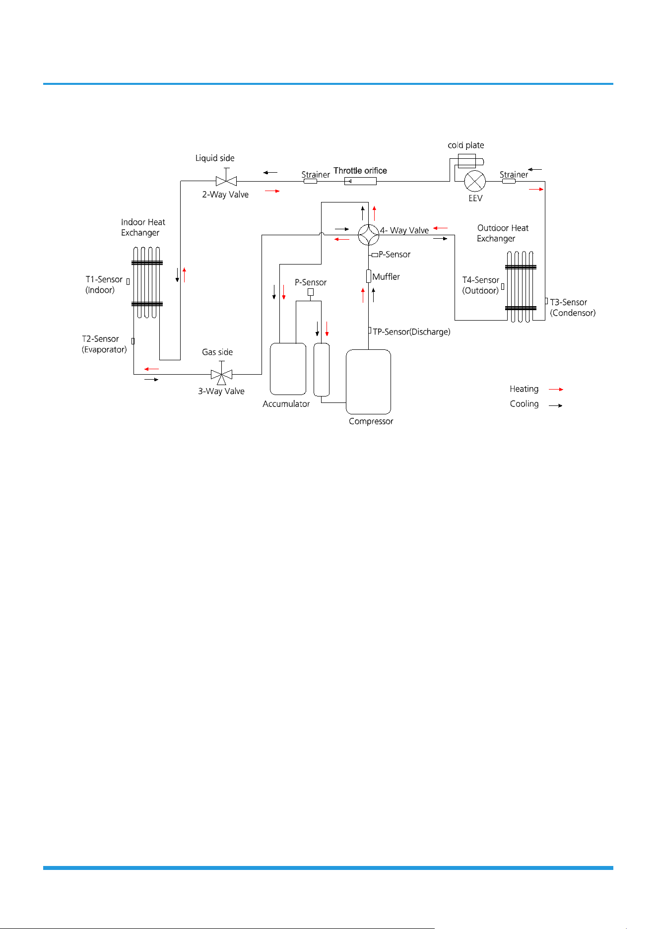
Specifications 23
MOD30-36HFN10-M1E
Specifications 24
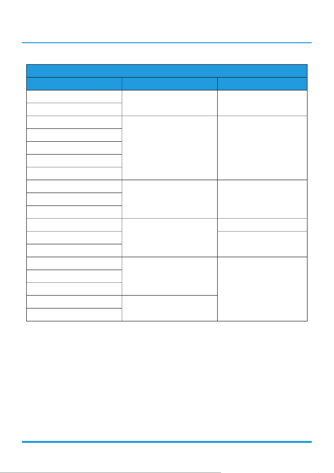
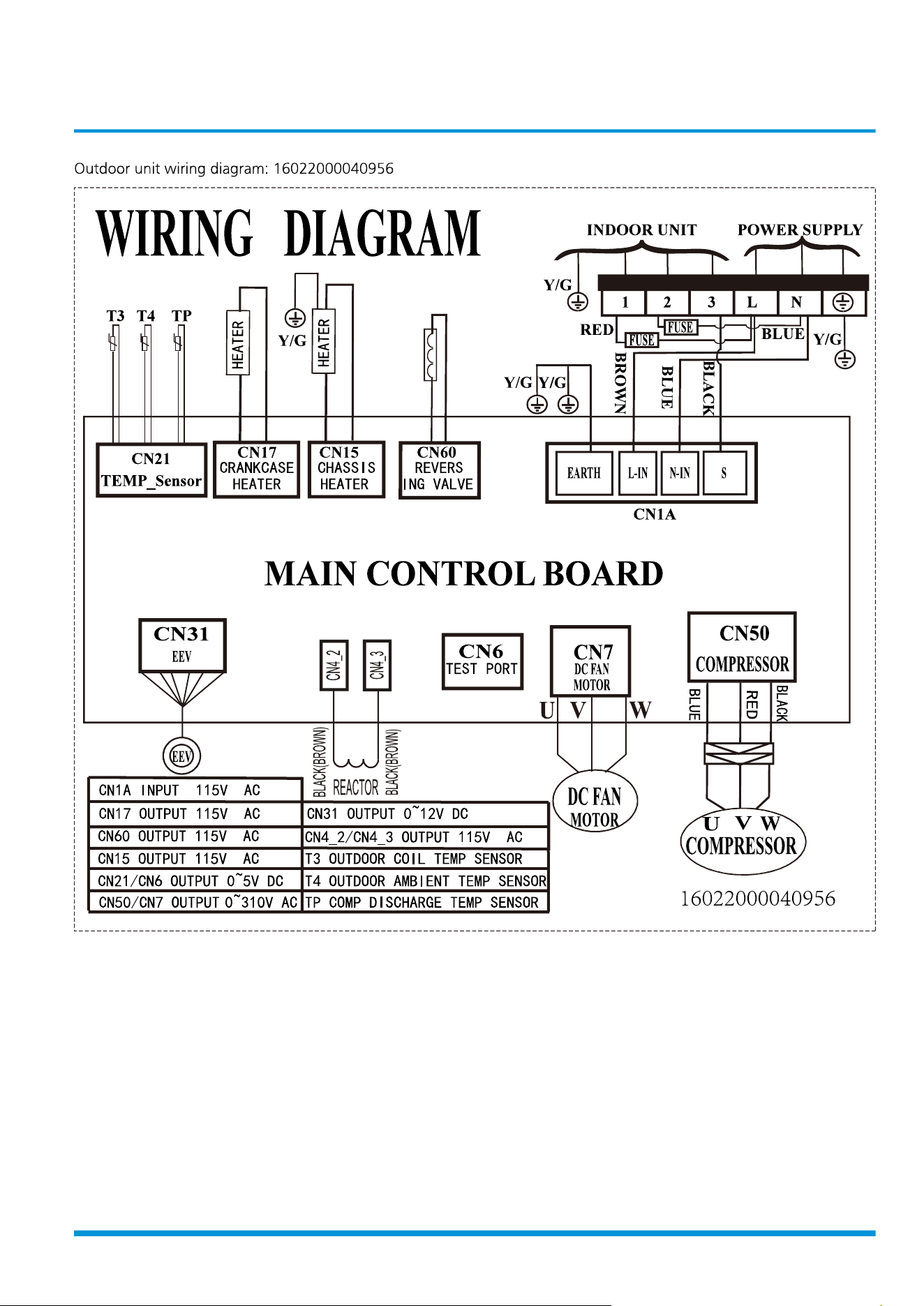
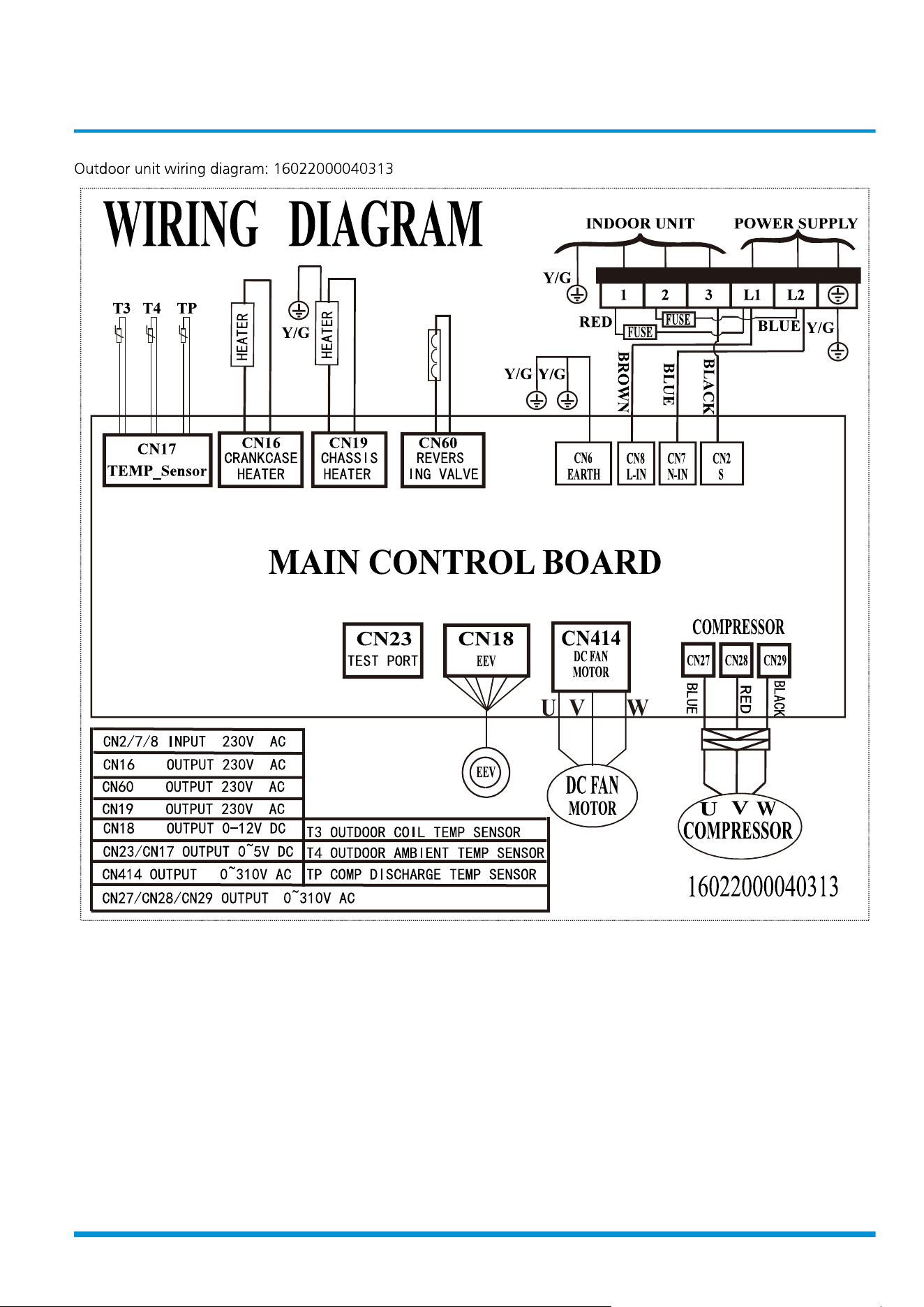
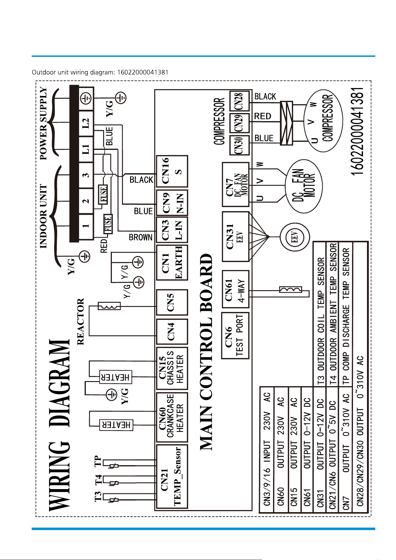
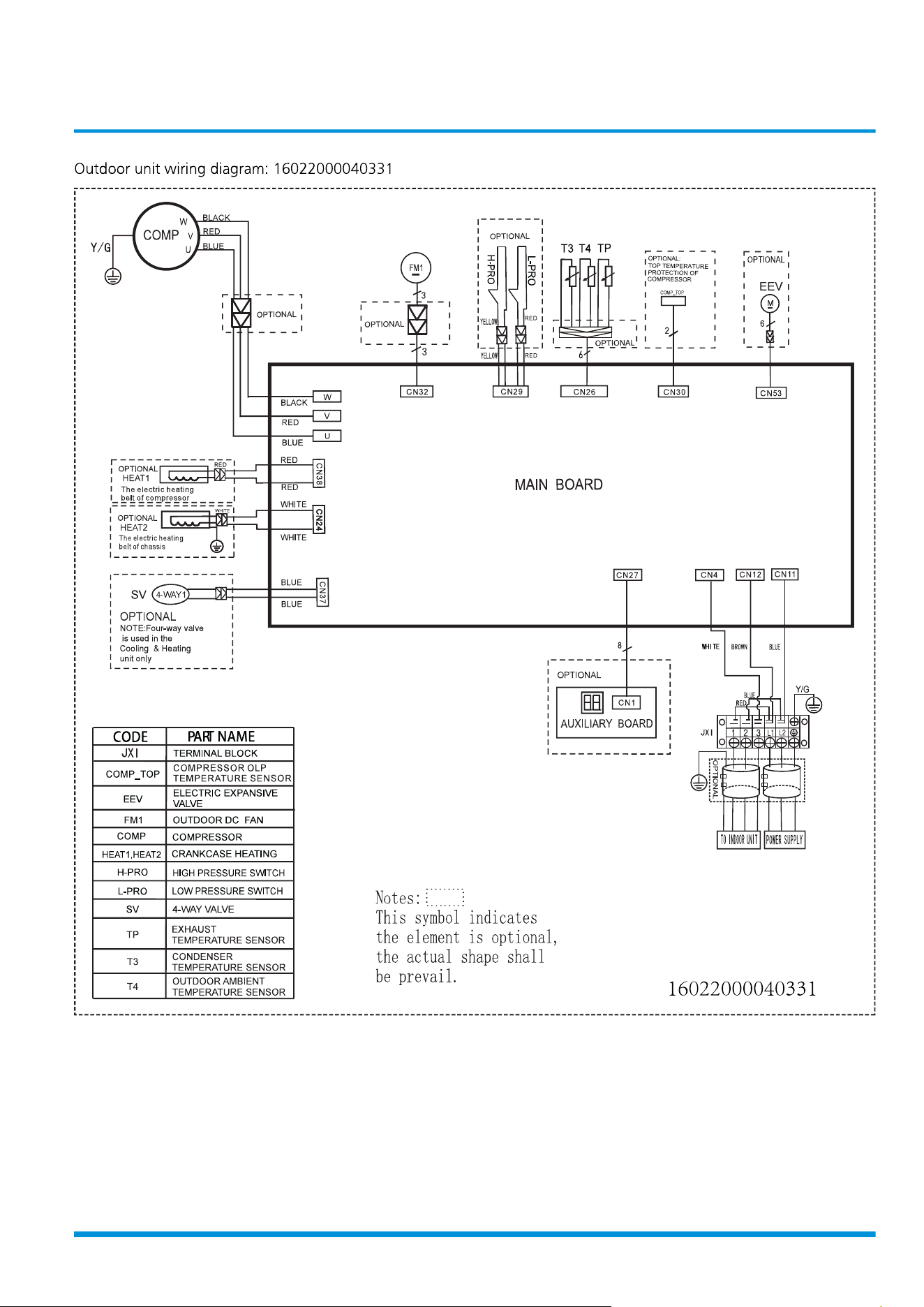
5. Electrical Wiring Diagrams
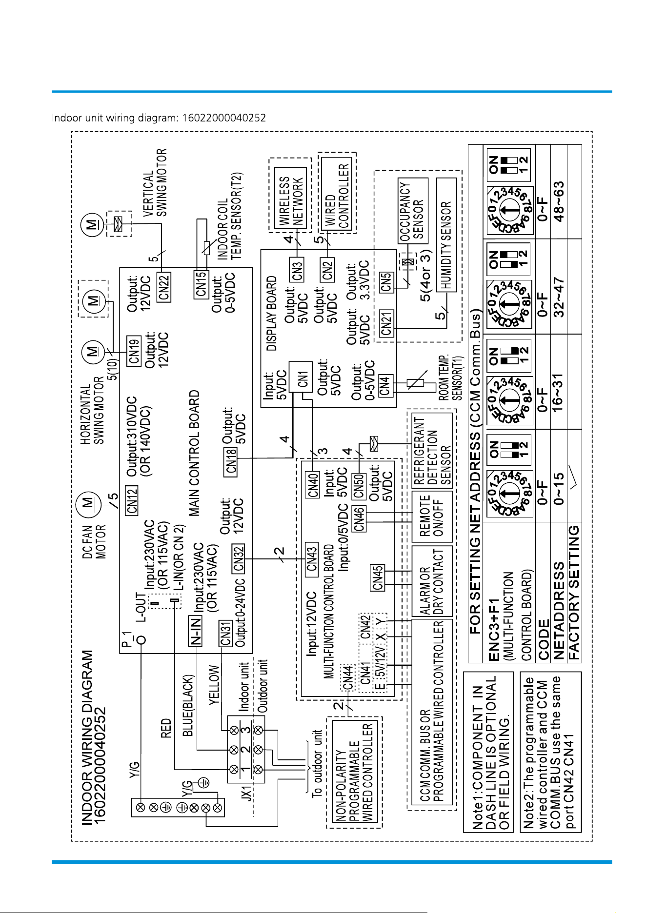
Indoor unit wiring diagram
Indoor Unit
IDU Model IDU Wiring Diagram
MSEPB-09HRFN10-B1
16022000040252
MSEPB-12HRFN10-B1
MSEPB-06HRFN10-M1
MSEPB-09HRFN10-M1
MSEPBM-12HRFN10-M1
MSEPC-06HRFN1-M1H
MSEPC-09HRFN1-M1H
MSEPC-12HRFN10-M1H
MSEPD-18HRFN10-M1H
MSEPC-18HRFN10-M1
MSEPD-24HRFN10-M1
MSEPD-30HRFN10-M1
MSEPDM-36HRFN10-M1E
MSEPD-33HRFN10-M1
Specifications 25
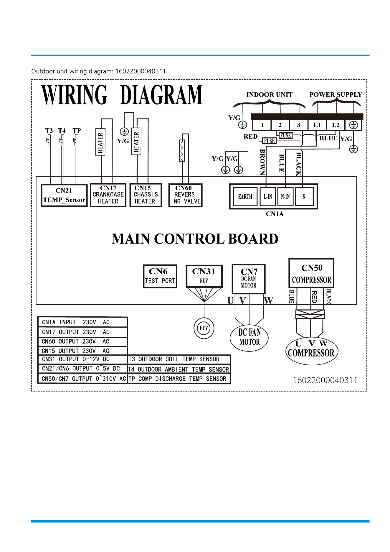
Outdoor unit wiring diagram and printed circuit board diagram
Outdoor Unit
ODU Model ODU Wiring Diagram ODU Printed Circuit Board
MOX230-09HFN10-B1
16022000040956
17122000062141
MOX230-12HFN10-B1
MOX230-06HFN10-M1X
16022000040311
17122000057661
MOX230-09HFN10-M1
MOX230-12HFN10-M1
MOX330-09HFN10-M1X
MOX330-12HFN10-M1X
MOX430-06HFN1-M1H
16022000041381
17122000057814
MOX430-09HFN1-M1H
MOX430-12HFN10-M1H
MOX430-18HFN10-M1
16022000040313
17122000048066
MOX430-18HFN10-M1X
17122000048064
MOD30-24HFN10-M1
MOD30-18HFN10-M1H
16022000040331
17122300007152
MOD30-24HFN10-M1X
MOD30-30HFN10-M1E
MOD30-33HFN10-M1X
16022000040650
MOD30-36HFN10-M1E
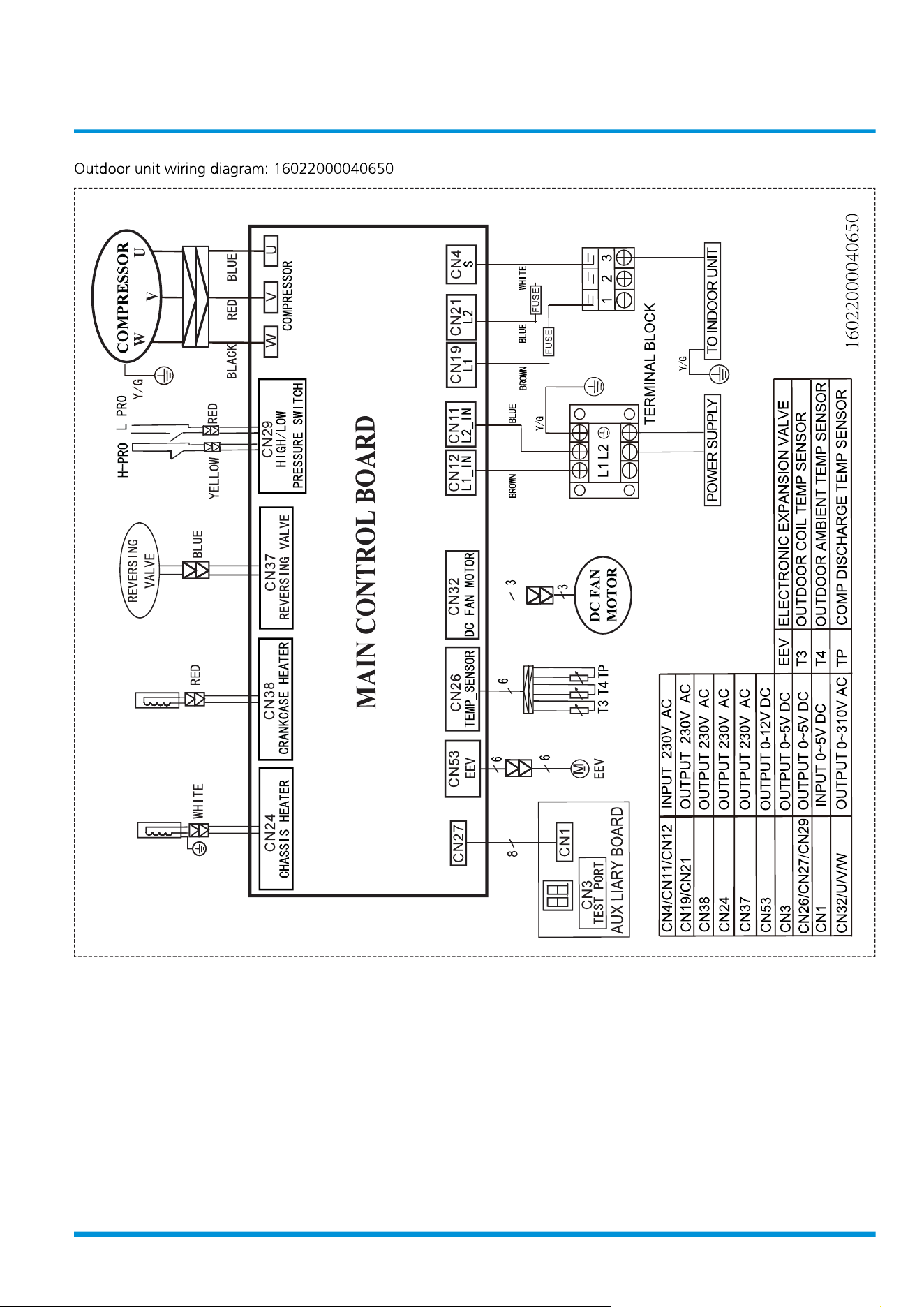
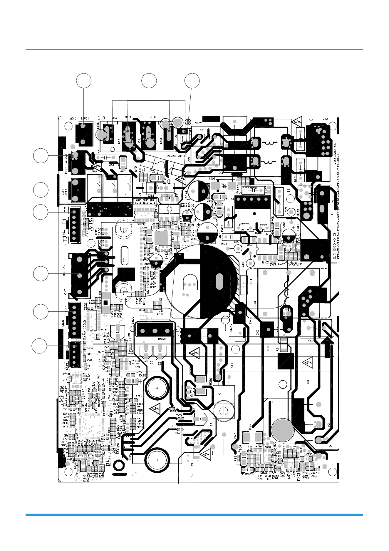
Outdoor unit printed circuit board diagram: 17122000057661
8
1
9
2
3
4
5
6
7
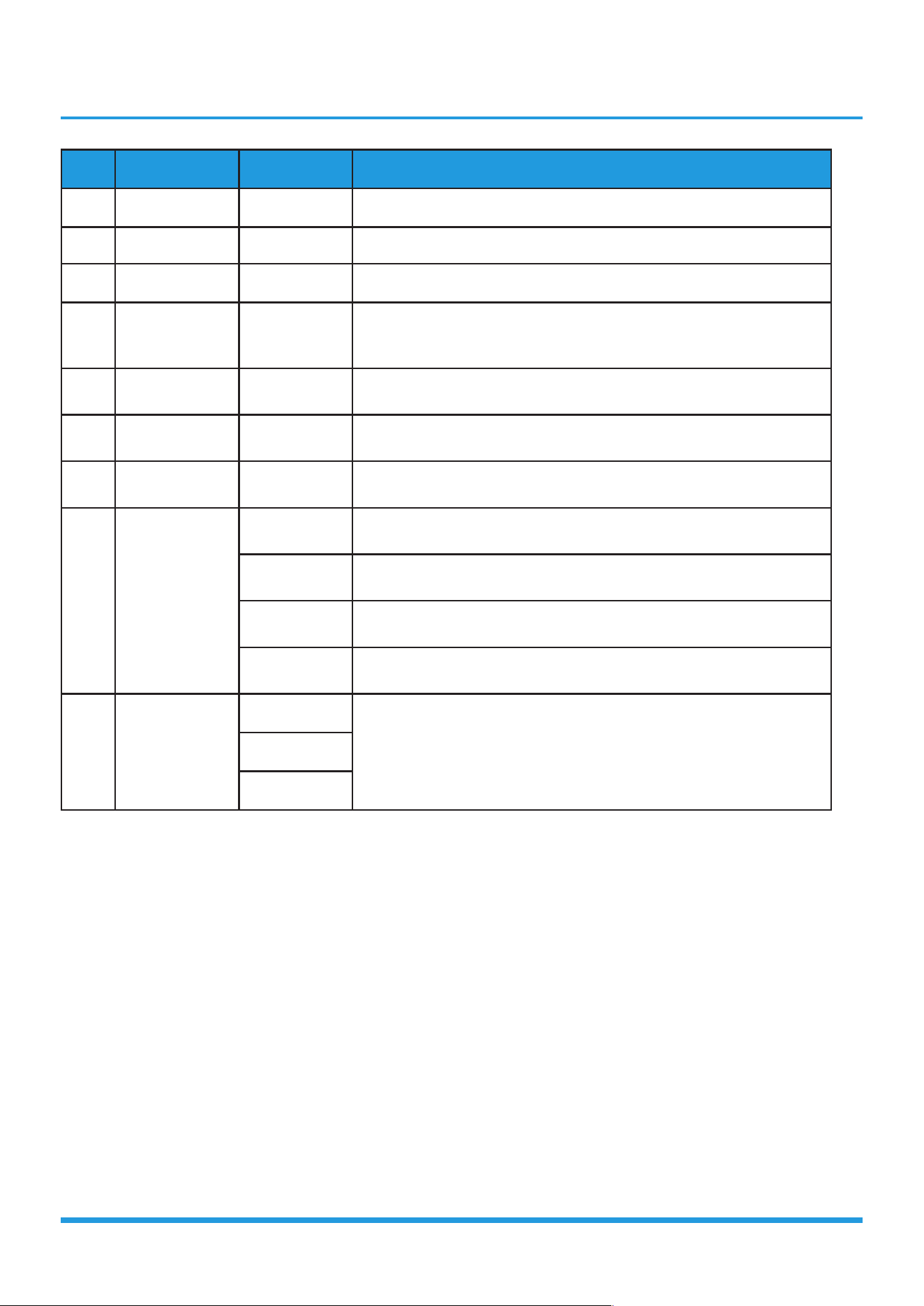
No. Name CN# Meaning
1 TESTPORT CN6 used for testing
2 PMV CN31 connect to electric expansion valve (Output:0~2V DC)
3 DC-FAN CN7 connect to DC fan (Output: 0~310V AC).
4 TP T4 T3 CN21
connect to pipe temp. sensor T3, ambient temp. sensor T4, exhaust
temp. sensor TP (Output: 0~5V DC)
5 HEAT1 CN17 connect to compressor heater (Output: 230V AC).
6 4-WAY CN60 connect to 4 way valve (Output: 230V AC)
7 HEAT2 CN15 connect to chassis heater (Output: 230V AC)
8 CN1A
CN16 S: connect to indoor unit communication
CN2 L_in: connect to L-line (230V AC input)
CN1 N_in: connect to N-line (230V AC input)
CN3 Earth
9 CN50
W
connect to compressor (Output: 0-310V AC)V
U
Note: This section is for reference only. Please take practicality as standard.
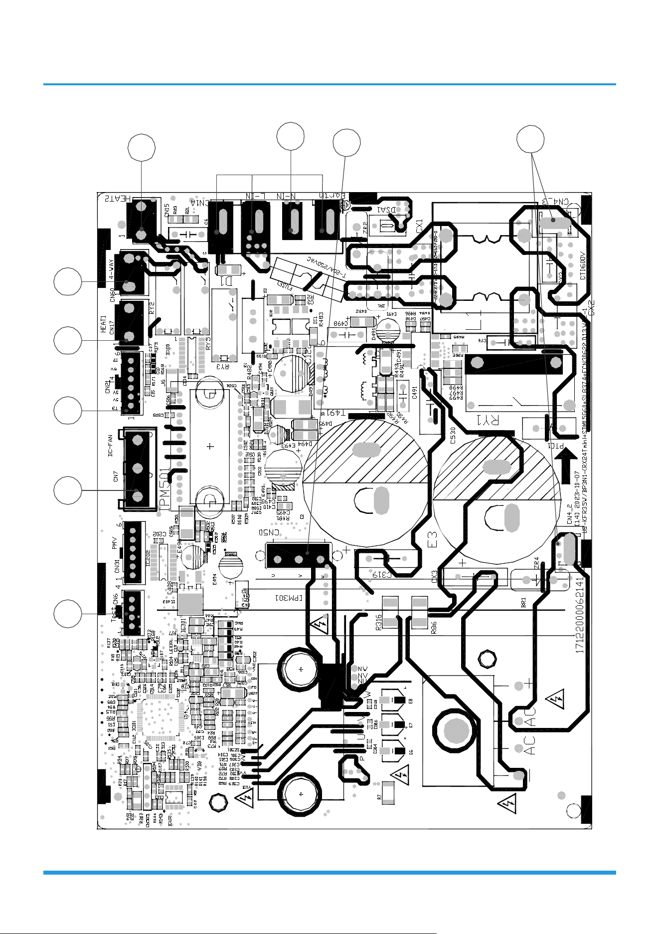
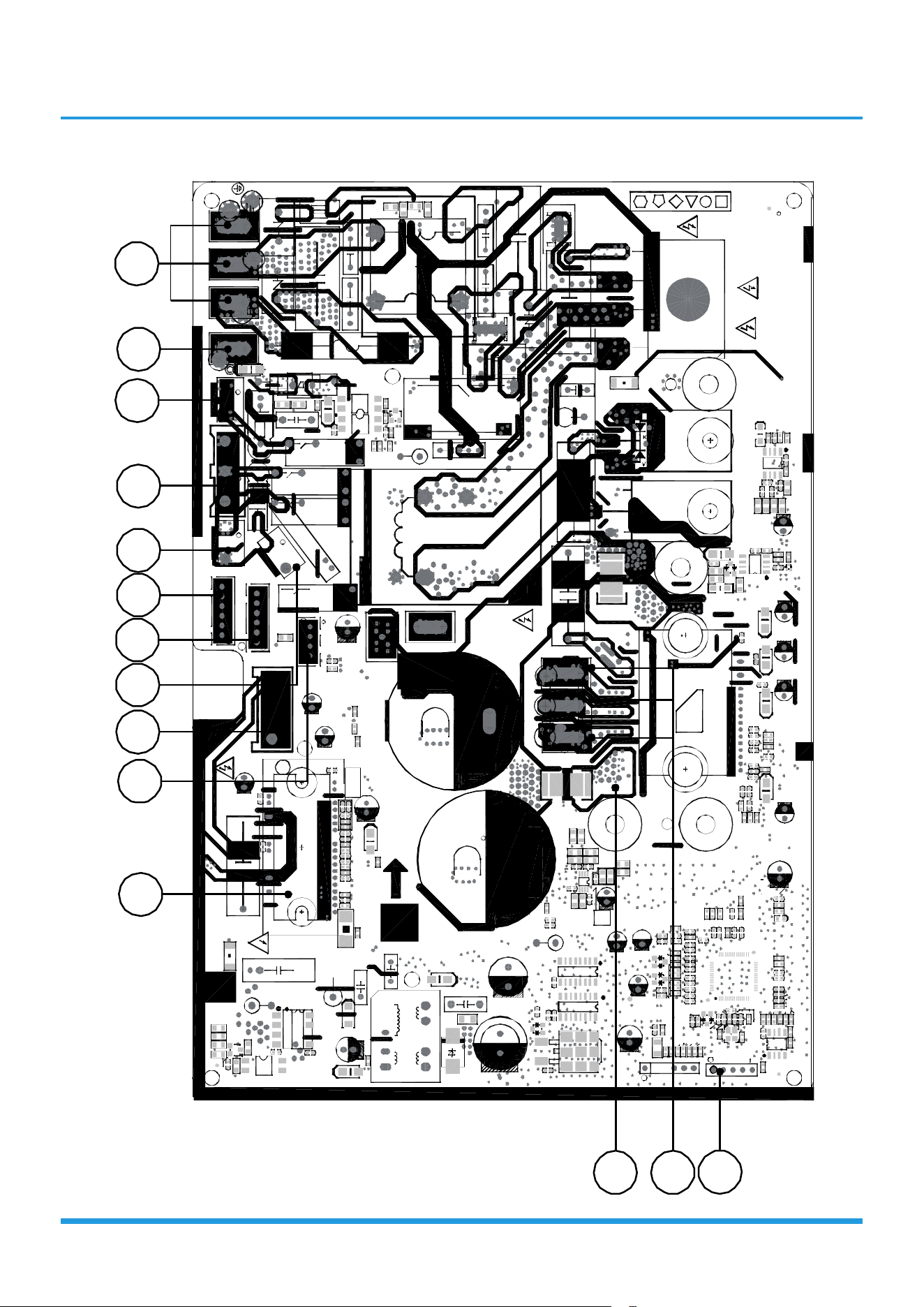
Outdoor unit printed circuit board diagram: 17122000062141
7
1
8
3
4
5
6
2
9
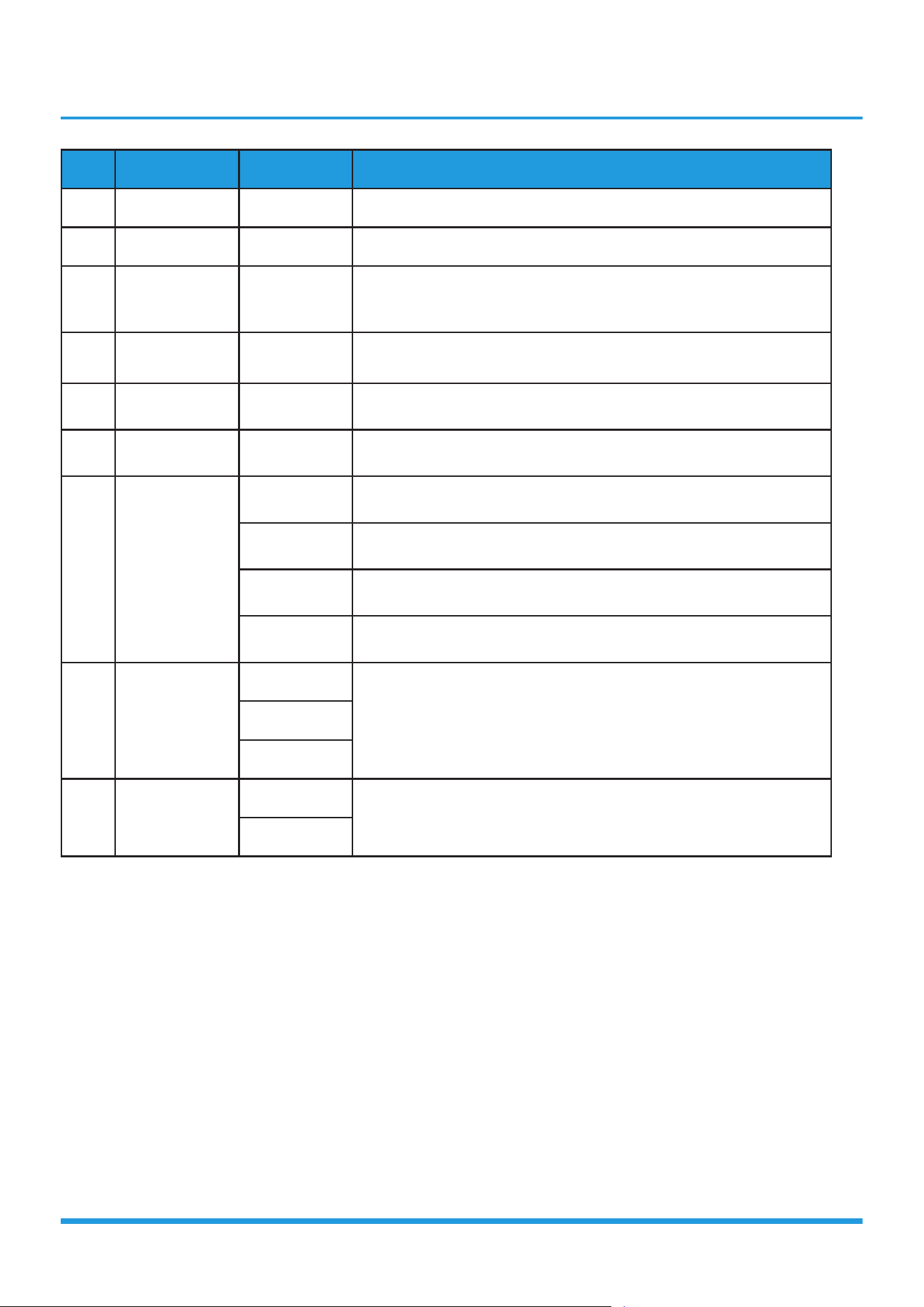
No. Name CN# Meaning
1 TESTPORT CN6 used for testing(Output:0~5 V DC)
2 DC-FAN CN7 connect to DC fan(Output:0~310 V AC)
3 TP T4 T3 CN21
connect to pipe temp. sensor T3, ambient temp. sensor T4, exhaust
temp. sensor TP(Output:0~5 VDC)
4 HEAT1 CN17 connect to compressor heater, 115V AC when is ON
5 4-WAY CN60 connect to 4 way valve, 115V AC when is ON.
6 HEAT2 CN15 connect to chassis heater, 115V AC when is ON
7 CN1A
/ S: connect to indoor unit communication
/ L_in: connect to L-line (115V AC input)
/ N_in: connect to N-line (115V AC input)
/ Earth
8 CN50
W
connect to compressor,0V AC (standby),0-310V AC (running)V
U
9 REACTOR
CN4_2
connect to reactor, 115V AC when is ON
CN4_3
Note: This section is for reference only. Please take practicality as standard.
Outdoor unit printed circuit board diagram: 17122000048064& 17122000048066
5V
T3 T4 TP
1
TESTPORT
1
T20 A
1
+
+
DC-FAN
DR
DR
MCU
EE
N
N
N
[1.4] 2019-10-15
780 5
S
N-IN
L-IN
K FR-7 2W/BP3 -(RX2 4Tmini+6A161+ PSS30 S92F6- AG+6822+ LMSR).D.13 .WP2-1
BLACK
RED
15V
5V
PMV
BL UE
Earth
HEAT2
HEA T1
4- WAY
AC-FAN
+
1
P
T3 0A/25 0VAC
171 22000 048064
+
D 401
C209
+
E201
L2 01
CN1 9
+
D8 01
L4
L3
C1 0
C9
C41 2
C407
IC4 01
R4 02
+
E4 01
C402
C4 01
R401
+
D4 02
R403
C 403
L 403
L402
L40 1
R626
+
DZ301
C N21
CN23
ZR 2
ZR1
CN505
FUS E1
L1
C803
D102
IC101
C 211
DR22
DR 21
CN15
CN14
C N6_ 1
C3 05
C31 4
C 315
R 611
R61 5
ZR3
R609
R528
R51 6
R51 5
R 512
R5 06
R 504
R5 02
R4 04
R31 5
R31 4
R31 3
R30 7
R3 05
R304
R 228
R227
R 226
R2 22
R2 21
R213
R2 12
R211
R2 10
R2 09
R 208
R 207
R2 05
R203
R 201
R1
+
E501
+
+
DZ5 01
D103
CN 18
C8
C61 4
C 608
C6 07
C60 6
C 520
C 516
C 514
C51 2
C511
C51 0
C50 1
C41 5
C41 0
C310
C2 05
C2 04
C2 03
C 115
C1 06
C6
C2
C615
R 508
IPM501
R525
C515
R511
R5 10
R50 9
R507
R50 5
C 508
C5 07
C 503
C5 19
C518
C 517
+
E502
+
E5 03
+
E504
R 407
R40 8
R42 1
IC4 05
R6 05
VP1CIN
V NC
NU
NW
NV
V-
W-
FO
VWB
VVB
U-
W+
V
V+
W
U+
VU B
P
U
VP1
VN 1
IPM1
L601
R41 2
IC403
+
E409
+
E404
D407
C409
C413
CN7
CN 6
CN 2
CN8
CN29 CN28 CN2 7
RY1
L6
L5
DAS1
R601
R301
+
-
AC
OUT
IN
~
~
RY3A
C3
C1
R62 5
R6 23
R 622
R 514
R5 13
C6 11
T1
CN 60
IC202
R1 04
R603
C20 2
R1 03
-
+
AC
AC
BR1
C801
C8 02
C103
C1 04
C1 05
C 212
C1 14
C1 16
C 208
C20 7
C2 06
C1 11
C 112
C 304
C3 09
C 317
C12
C4 04
C4 05
C408
C60 1
C60 5
C60 4
C 612
C 613
D 603
+
DZ30 4
+
DZ30 3
+
DZ302
+
DZ601
E601
IC801
IC802
IC2 03
IC4 04
Q80 1
R 804
R1 05
R110
R1 11
R22 5
R 215
R806
R80 5
R 809
R8 10
R8 08
R 807
R2 24
R2 17
R223
R216
R22 0
R 219R218
R2 02
R20 6
R 106
R1 07
R 302
R406
R4 05
R6 07
R 602
R6 04
R61 4
R 608
R6 10
R61 2
R61 6
R6 17
R618
R6 19
R 620
R 621
+
D 404
R2 04
C31 6
C 307
C30 8
C313
C31 2
C 311
R3 10
R3 06
R 308
R3 09
R 312
R3 11
R4 26
C318
C3 19
C5 13
R 317
R 316
R 318
R3 19
R3 20
R6 24
+
E301
+
E302
+
E304
+
E303
C20 1
C301
C302
C303
+
D6 02
IC201
C 603
R60 6
R109
R C1
RC 2
RY3
RY2
R10 8
+
D403
PTC1
+
E2
RY4
C5 09
+
D8 02
CN 16
RY5
+
E1
R61 3
E
C
G
Q601
R 801
R8 02
+
LED 101
1
3
OSC1 01
CN17
R8 03
C4
CN5
C610
+
D6 05
IC6 02
IC601
D6 04
C5
A
D601
C6 09
C10 1
+
E405
C7
CN4 14
+
E6 02
C 804
+
E202
+
E203
+
E204
R5 03
R 119
D1 01
R2 14
R1 01
R10 2
C 210
C 109
C1 10
C1 07
C 102
C 108
E60 3
R3 21
1
CN 506
IC6 03
13
14
12
12
3
4
56
7
9
8
10
11
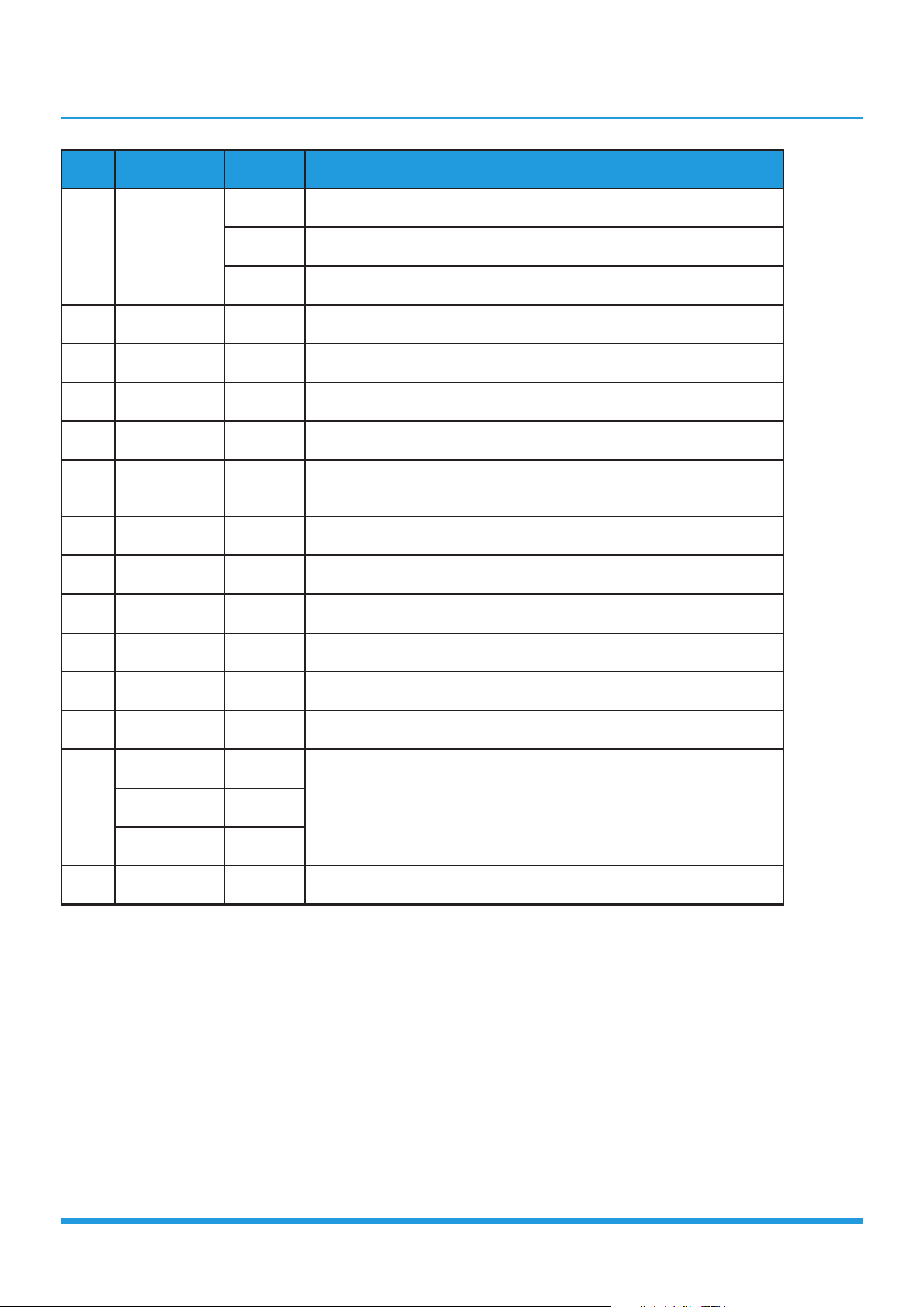
No. Name CN# Meaning
1 Power Supply
CN6 Earth: connect to Ground
CN7 N_in: connect to N-line (230V AC input)
CN8 L_in: connect to L-line (230V AC input)
2 S CN2 S: connect to indoor unit communication(230V AC input)
3 4-WAY CN60 connect to 4 way valve(Output: 230V AC)
4 AC-FAN CN5 connect to AC fan
5 HEAT2 CN19 connect to chassis heater(Output: 230V AC)
6 TP T4 T3 CN17
connect to pipe temp. sensor T3, ambient temp. sensor T4, exhaust
temp. sensor TP(Output: 0~5V DC)
7 PMV CN18 connect to Electric Expansion Valve
8 HEAT1 CN16 connect to compressor heater(Output: 230V AC)
9 DC-FAN CN414 connect to DC fan(Output: 0~310V AC)
10 TESTPORT CN23 used for testing
11 FAN_IPM IPM501 IPM for DC fan
12 COMP_IPM IPM1 IPM for compressor
13
U CN27
connect to compressor(Output: 0~310V AC)V CN28
W CN29
14 EE_PORT CN505 EEPROM programer port
Note: This section is for reference only. Please take practicality as standard.
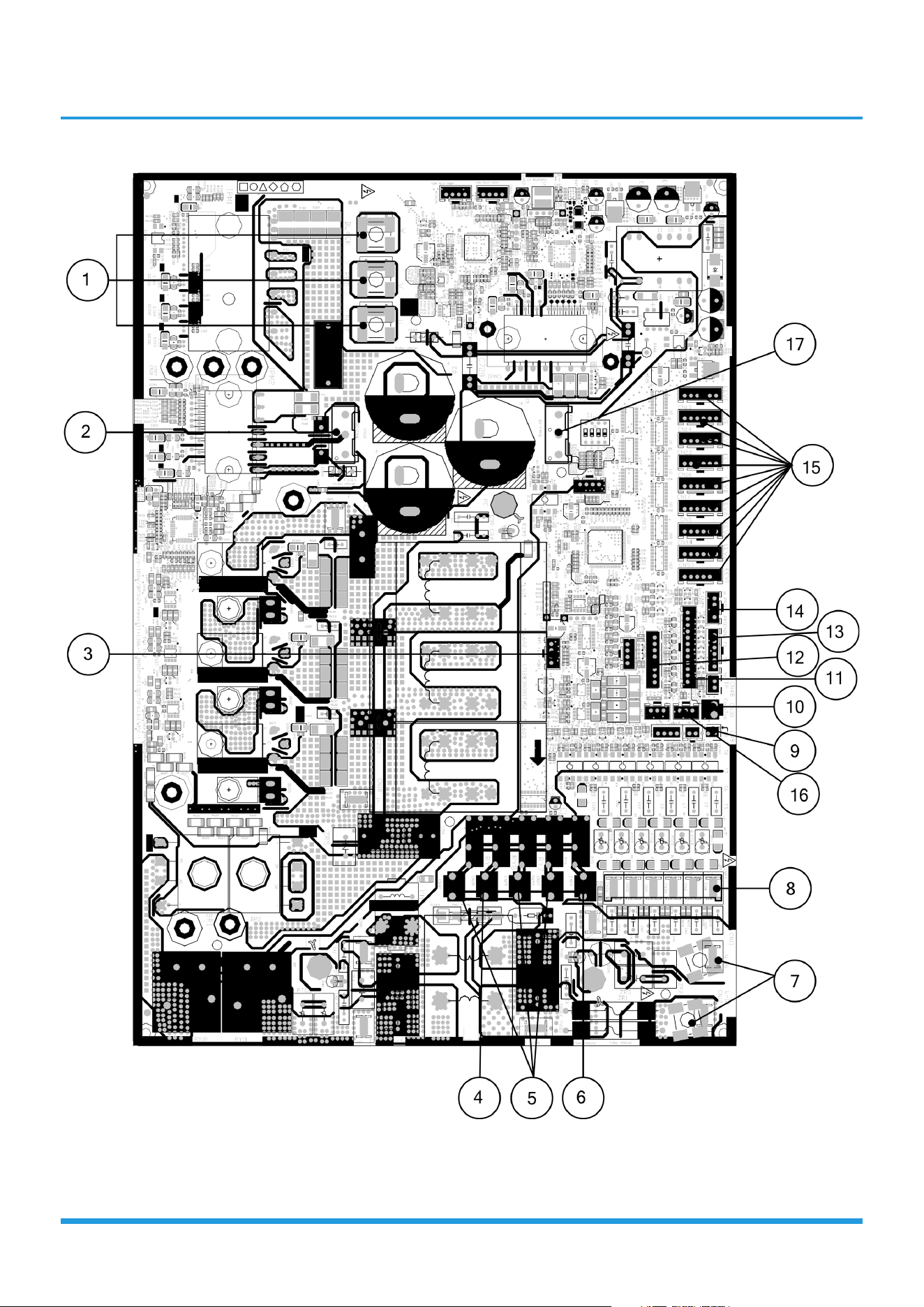
Outdoor unit printed circuit board diagram: 17122300007152
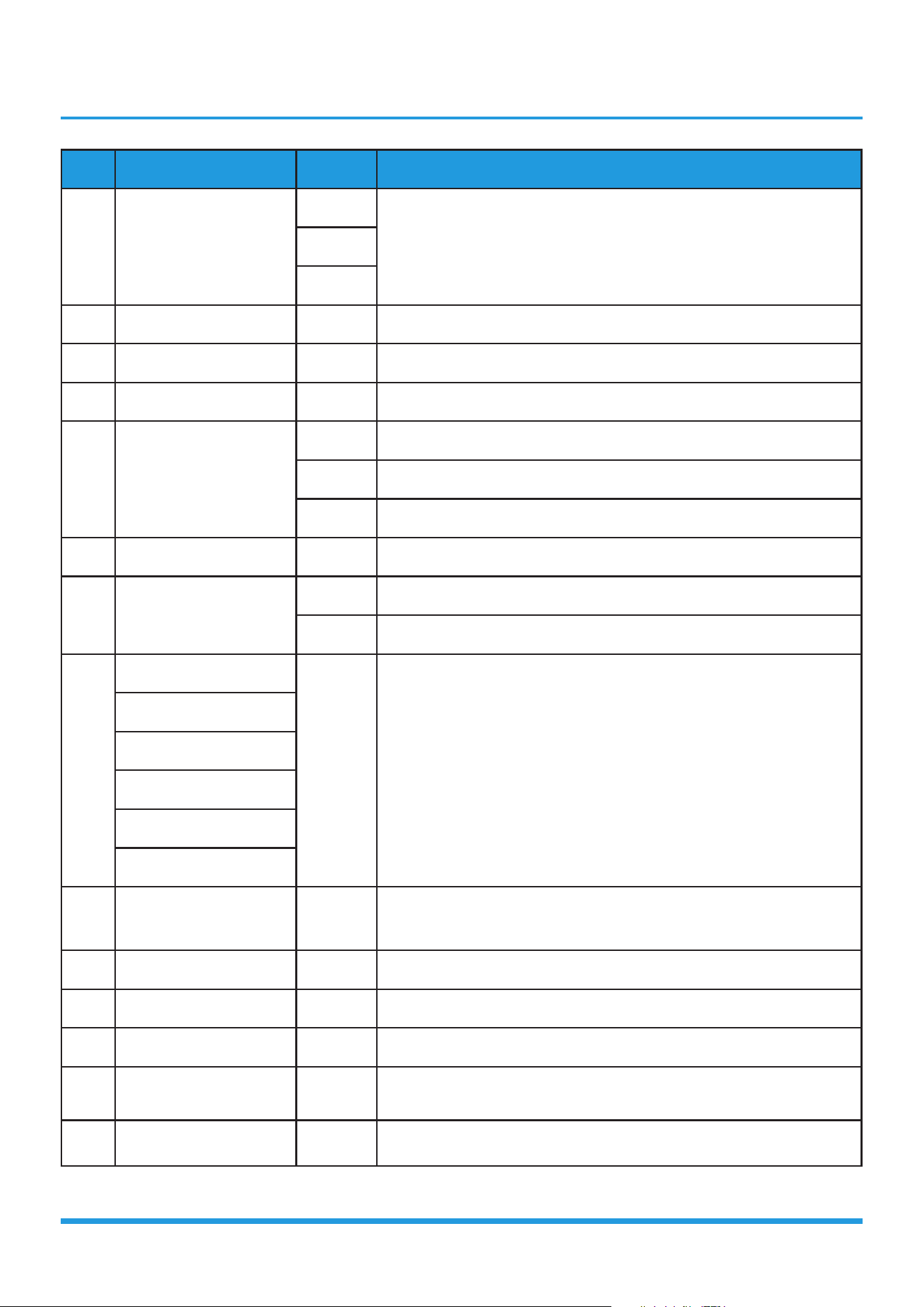
No. Name CN# Meaning
1 COMPRESSOR
W
connect to compressor(Output: 0~310V AC)V
U
2 DC-FAN1 CN32 connect to DC fan(Output: 0~310V AC)
3 TESTPORT CN45 used for testing
4 HEAT_Y CN38 connect to compressor heater(Output: 230V AC)
5 4-WAY
CN37 connect to 4 way valve 1(Output: 230V AC)
CN25 connect to 4 way valve 2(Output: 230V AC)
CN42 connect to 4 way valve 3(Output: 230V AC)
6 HEAT_D CN24 connect to chassis heater(Output: 230V AC)
7 Power Supply
CN11 N_in: connect to N-line (230V AC input)
CN12 L_in: connect to L-line (230V AC input)
8
S-A
CN43 S: connect to indoor unit communication(230V AC input)
S-B
S-C
S-D
S-E
S-F
9 TBH-IN TBH-OUT T3B TF CN9
connect to cold plate inlet temp. sensor TBH-IN, cold plate outlet temp.
sensor TBH-OUT, condenser coil middle temp. sensor T3B, refrigerant
tube inlet temp. sensor TF
10 OLP TEMP. SENSOR CN30 connect to compressor top temp. sensor (Output: 0~5V DC)
11 T2B CN28 connect to evaporator coil outlet temperature sensor T2B
12 / CN27 connect to key board CN1
13 T3 T4 TP CN26
connect to condenser coil temp. sensor T3, ambient temp. sensor T4,
exhaust temp. sensor TP(Output: 0~5V DC)
14 H-PRO,L-RPO CN29
connect to high and low pressure switch(pin1-pin2&pin3-pin4:5VDC
pulse wave)
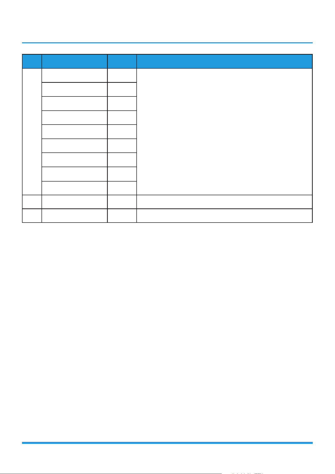
No. Name CN# Meaning
15
EEVA CN17
connect to electric expansion valve(Output: 0~12V DC)
EEVB CN16
EEVC CN22
EEVD CN14
EEVE CN13
EEVF CN1
EEV1 CN53
EEV2 CN44
EEV3 CN3
16 H_YL CN49 connect to high pressure sensor
17 DC-FAN2 CN10 connect to DC fan(Output: 0~310V AC)
Note: This section is for reference only. Please take practicality as standard.

Contents
1. Display Function ....................................................................................................2
2 Safety Features ......................................................................................................3
3. Basic Functions .......................................................................................................4
3.1 Abbreviation ..................................................................................................4
3.2 Fan Mode ......................................................................................................4
3.3 Cooling Mode ...............................................................................................4
3.4 Heating Mode(Heat Pump Units) ...................................................................5
3.5 Auto-mode ....................................................................................................7
3.6 Drying Mode .................................................................................................7
3.7 Forced Operation Function ............................................................................7
3.8 Timer Function ..............................................................................................8
3.9 Sleep Function ...............................................................................................8
3.10 Auto-Restart Function ....................................................................................8
3.11 Active Clean function ....................................................................................8
3.12 Follow me(Optional) ......................................................................................8
3.13 8°C Heating(Optional) ...................................................................................8
3.14 Silence (Optional) ..........................................................................................8
3.15 ECO function(Optional) .................................................................................9
3.16 Electrical energy consumption control function(Optional) ...............................9
3.17 Breeze away function(Optional) .....................................................................9
3.18 Wireless control(optional) ..............................................................................9
Product Features
Product Features
Product Features 2
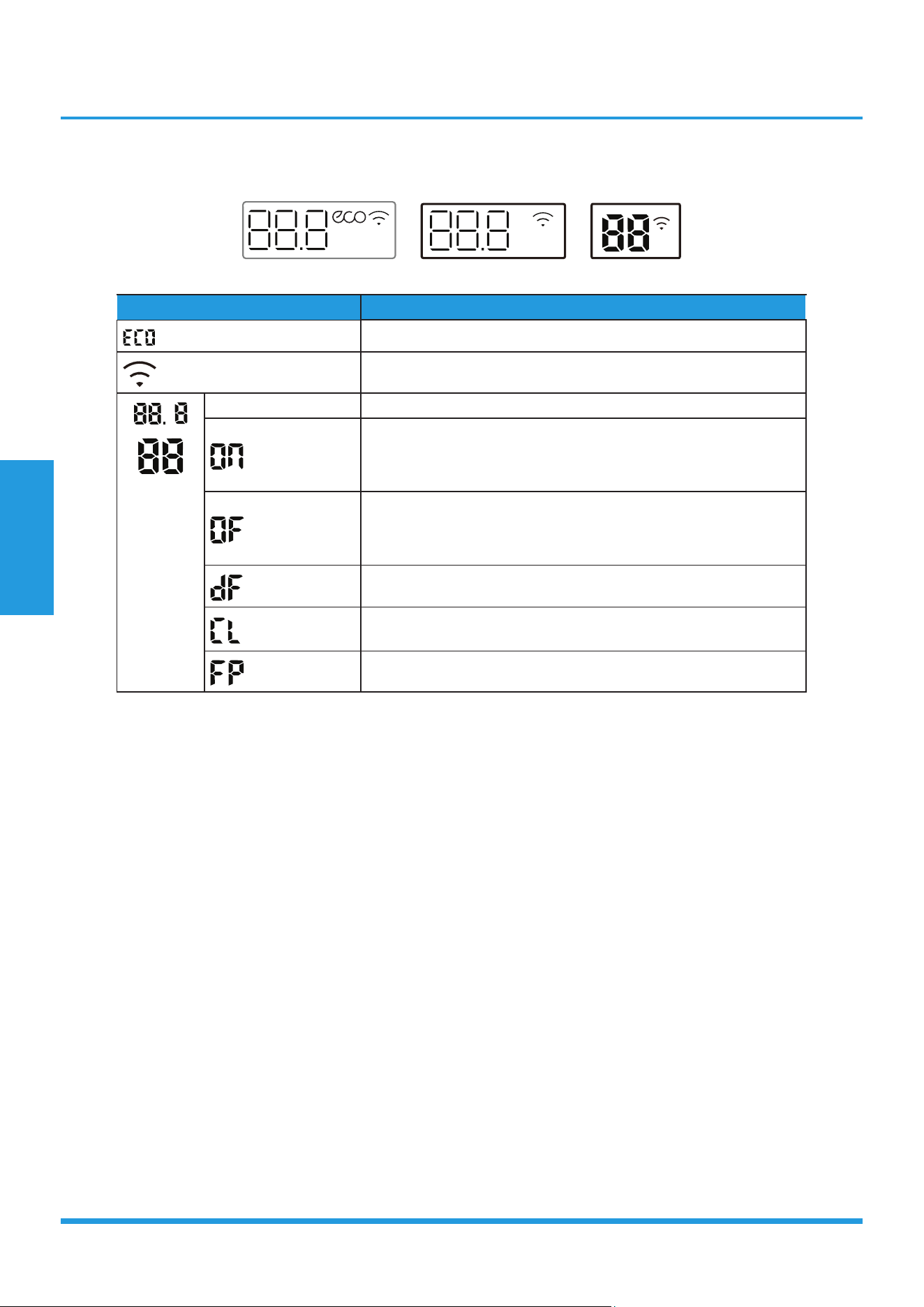
1. Display Function
Unit display functions
(A) (B) (C)
Display Function
ECO function (available on select units only)
when Wireless Control feature is activated(some units)
Temperature value Temperature
(3s)
Timer ON is set.
Activation of , Fresh, Swing, Turbo, ECO, Breeze away, ECO
intelligent or Silence
(3s)
Timer OFF is set.
Cancellation of Fresh, Swing, Turbo, ECO, Breeze away, ECO
intelligent or Silent
Defrost
Active Clean (For Inverter split type) or self-cleaning(For Fixed-
speed type)
Heating in room temperature under 8°C
Note: Please select the display function according to your purchase product.

Product Features 3
2. Safety Features
Compressor three-minute delay at restart
Compressor functions are delayed for up to ten seconds upon the fi rst startup of the unit, and are delayed for up
to three minutes upon subsequent unit restarts.
Automatic shutoff based on discharge temperature
If the compressor discharge temperature exceeds a certain level for a period of time, the compressor ceases operation.
Automatic shutoff based on fan speed
If the indoor fan speed registers below 200RPM or over 2100RPM for an extended period of time, the unit ceases
operation and the corresponding error code is displayed on the indoor unit.
Inverter module protection
The inverter module has an automatic shutoff mechanism based on the unit’s current, voltage, and temperature. If
automatic shutoff is initiated, the corresponding error code is displayed on the indoor unit and the unit ceases operation.
Indoor fan delayed operation
• When the unit starts, the louver is automatically activated and the indoor fan will operate after a period of setting
time or the louver is in place.
• If the unit is in heating mode, the indoor fan is regulated by the anti-cold wind function.
Compressor preheating
Preheating is automatically activated when T4 sensor is lower than setting temperature.
Sensor redundancy and automatic shutoff
• If one temperature sensor malfunctions, the air conditioner continues operation and displays the corresponding error
code, allowing for emergency use.
• When more than one temperature sensor is malfunctioning, the air conditioner ceases operation.
Product Features 4
3. Basic Functions
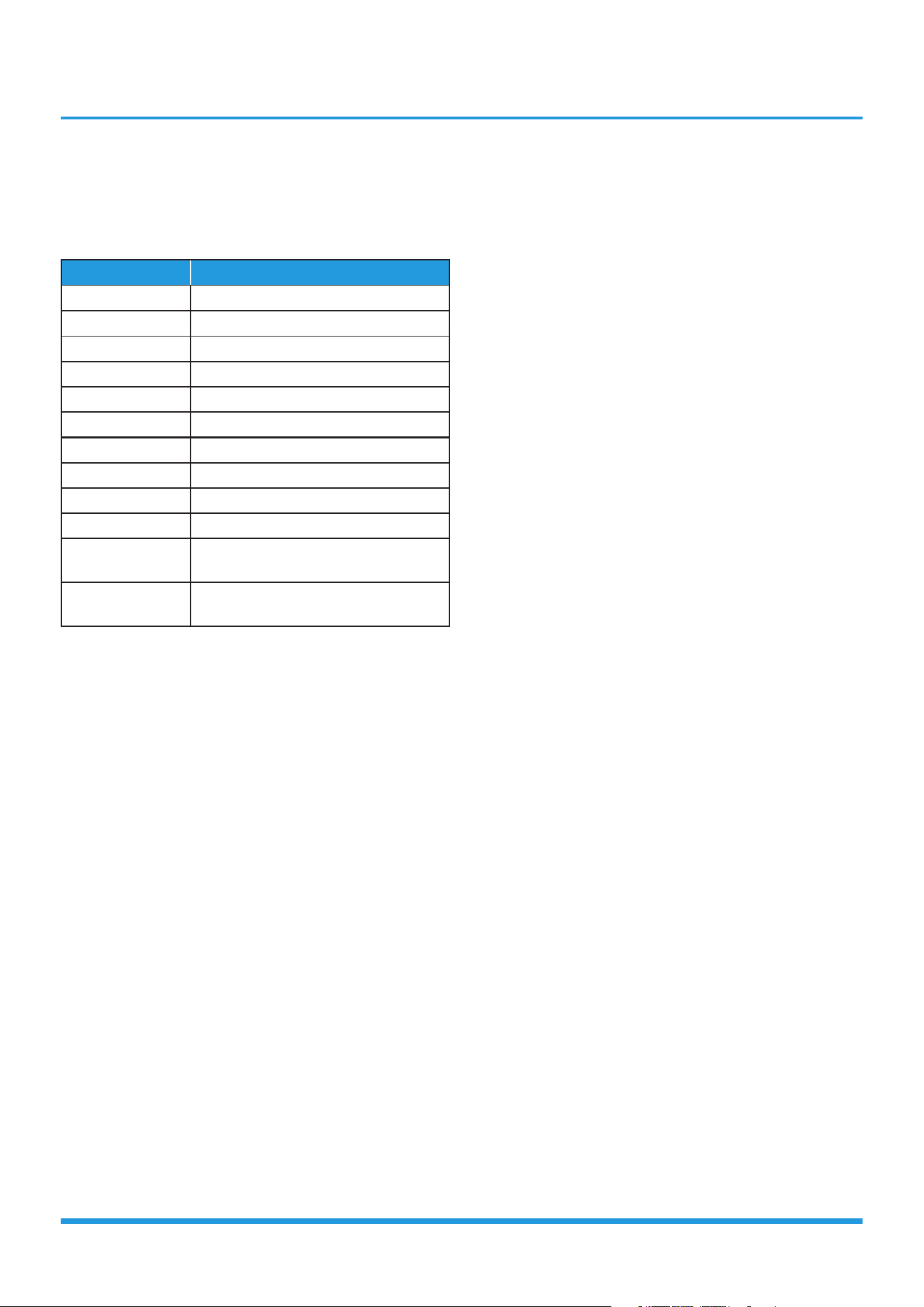
3.1 Abbreviation
Unit element abbreviations
Abbreviation Element
T1 Indoor room temperature
T2 Coil temperature of evaporator
T3 Coil temperature of condenser
T4 Outdoor ambient temperature
Tsc Adjusted setting temperature
TP Compressor discharge temperature
CDIFTEMP Cooling shutdown temperature
HDIFTEMP2 Heating shutdown temperature
TCDI1 Enter defrost temperature
TCDE1 Exit defrost temperature1
TCDE2
Exit defrost temperature2 (maintain
for a period of time )
TIMING_
DEFROST_TIME
Enter defrost time
In this manual, such as CDIFTEMP, HDIFTEMP2, TCDE1,
TCDE2, TIMING_DEFROST_TIME...etc., they are well-
setting parameter of EEPROM.
3.2 Fan Mode
When fan mode is activated:
• The outdoor fan and compressor cease operation.
• Temperature control is disabled and indoor room
temperature is displayed.
• The indoor fan speed can be set to 1%~100%, or
auto.
• The louver operations are identical to those in cooling
mode.
• Auto fan: In fan-only mode, AC operates the same as
auto fan in cooling mode with the temperature set at
24°C(75°F).(Tsc =24°C(75°F))
3.3 Cooling Mode
3.3.1 Compressor Control
Reach the configured temperature:
1) When the compressor runs continuously for within 120
minutes.
• If the following conditions are satisfied, the
compressor ceases operation.
• Calculated frequency(fb) is less than minimum limit
frequency(FminC).
• Compressor runs at FminC more than 10 minutes
• T1 is lower than or equal to (Tsc-CDIFTEMP-
0.5°C(32.9°F))
Note: CDIFTEMP is EEPROM setting parameter. It is
2°C(35.6°F) usually.
2) When the compressor runs continuously for more than
120 minutes.
• If the following conditions are satisfied, the
compressor ceases operation.
• Calculated frequency(fb) is less than minimum limit
frequency(FminC).
• Compressor runs at FminC more than 10 minutes.
• T1 is lower than or equal to (Tsc-CDIFTEMP).
Note: CDIFTEMP is EEPROM setting parameter. It is
2°C(35.6°F) usually.
3) If one of the following conditions is satisfied, not judge
protective time.
• Compressor running frequency(fr) is more than test
frequency(TestFre).
• Compressor running frequency is equal to test
frequency, T4 is more than 15°C(59°F) or T4 fault.
• Change setting temperature.
• Turn on/off turbo or sleep function
• Various frequency limit shutdown occurs.
3.3.2 Indoor Fan Control
1) In cooling mode, the indoor fan operates continuously.
The fan speed can be set to 1%-100%, or auto.
2) Auto fan
For DC fan motor units:
• Descent curve
• When T1-Tsc is lower than 3.5°C(6.3°F), fan speed
reduces to 80%;
• When T1-Tsc is lower than 1°C(1.8°F), fan speed
reduces to 60%;
• When T1-Tsc is lower than 0.5°C(0.9°F), fan speed
reduces to 40%;
• When T1-Tsc is lower than 0°C(0°F), fan speed
reduces to 20%;
• When T1-Tsc is lower than -0.5°C(-0.9°F), fan speed
reduces to 1%.
• Rise curve
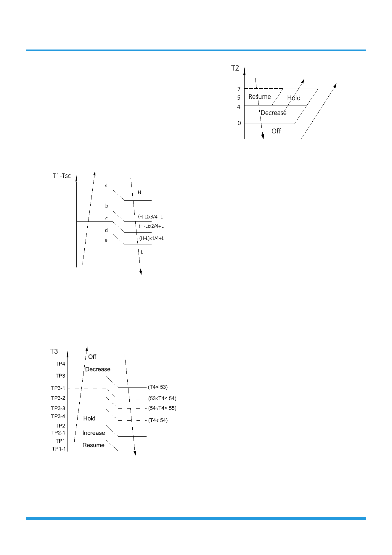
Product Features 5
• When T1-Tsc is higher than or equal to 0°C(0°F),
fan speed increases to 20%;
• When T1-Tsc is higher than or equal to
0.5°C(0.9°F), fan speed increases to 40%;
• When T1-Tsc is higher than or equal to 1°C(1.8°F),
fan speed increases to 60%;
• When T1-Tsc is higher than or equal to
1.5°C(2.7°F), fan speed increases to 80%;
• When T1-Tsc is higher than or equal to 4°C(7.2°F),
fan speed increases to 100%.
For AC fan motor units:
3.3.3 Outdoor Fan Control
• The outdoor unit will be run at different fan speed
according to T4 and compressor running frequency..
• For different outdoor units, the fan speeds are
different.
3.3.4 Condenser Temperature Protection
When the condenser temperature exceeds a configured
value, the compressor ceases operation.
3.3.5 Evaporator Temperature Protection
• Off: Compressor stops.
• Decrease: Decrease the running frequency to the lower
level per 1 minute.
• Hold: Keep the current frequency.
• Resume: No limitation for frequency.
3.4 Heating Mode(Heat Pump Units)
3.4.1 Compressor Control
1) Reach the configured temperature
• If the following conditions are satisfied, the
compressor ceases operation.
• Calculated frequency(fb) is less than minimum limit
frequency(FminH).
• Compressor runs at FminH more than 10 minutes.
• T1 is higher than or equal to Tsc+ HDIFTEMP2.
Note: HDIFTEMP2 is EEPROM setting parameter. It is
2°C(35.6°F) usually.
• If one of the following conditions is satisfied, not
judge protective time.
• Compressor running frequency(fr) is more than test
frequency(TestFre).
• When compressor running frequency is equal to
test frequency, T4 is more than 15°C(59°F) or T4
fault.
• Change setting temperature.
• Turn on/off turbo or sleep function.
2) When the current is higher than the predefined safe
value, surge protection is activated, causing the
compressor to cease operations.
3.4.2 Indoor Fan Control:
1) In heating mode, the indoor fan operates continuously.
The fan speed can be set to 1%-100%, or mute.And
the anti-cold wind function has the priority.
• Anti-cold air function
• The indoor fan is controlled by the indoor
temperature T1 and indoor unit coil temperature
T2.
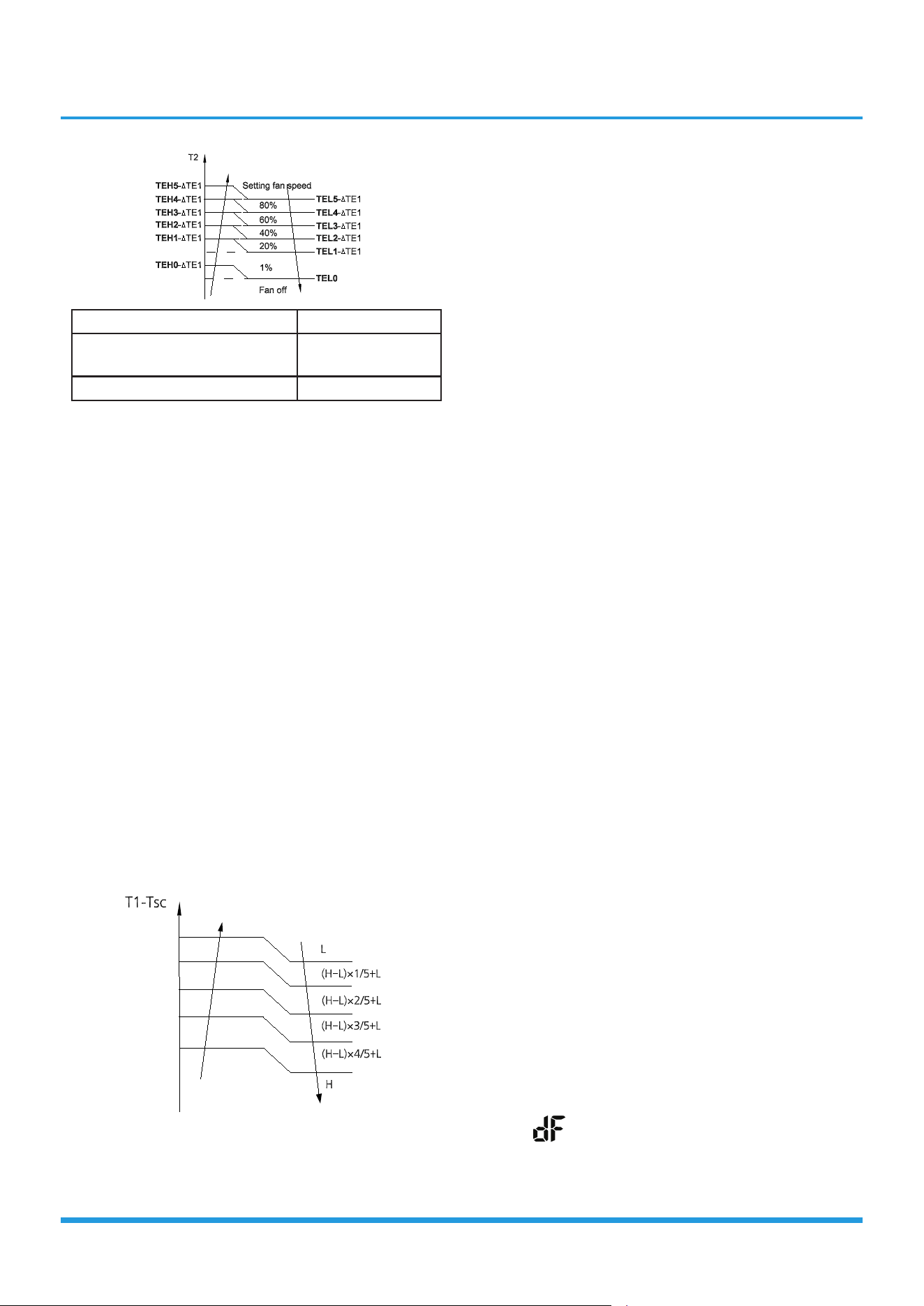
Product Features 6
T1 ≥ 19°C(66°F) ΔTE1=0
15°C(59°F)≤T1<19°C(66°F)
ΔTE1=19°C-T1
(66°F-T1)
T1<15°C(59°F) ΔTE1=4°C(7.2°F)
2) Auto fan
For DC fan motor units:
• Rise curve
• When T1-Tsc is higher than -1.5°C(-2.7°F), fan
speed reduces to 80%;
• When T1-Tsc is higher than 0°C(0°F), fan speed
reduces to 60%;
• When T1-Tsc is higher than 0.5°C(0.9°F), fan speed
reduces to 40%;
• When T1-Tsc is higher than 1°C(1.8°F), fan speed
reduces to 20%.
• Descent curve
• When T1-Tsc is lower than or equal to 0.5°C(0.9°F),
fan speed increases to 40%;
• When T1-Tsc is lower than or equal to 0°C(0°F), fan
speed increases to 60%;
• When T1-Tsc is lower than or equal to -1.5°C(-
2.7°F), fan speed increases to 80%;
• When T1-Tsc is lower than or equal to -3°C(5.4°F),
fan speed increases to 100%.
For AC fan motor units:
3.4.3 Outdoor Fan Control:
• The outdoor unit will be run at different fan speed
according to T4 and compressor running frequency.
• For different outdoor units, the fan speeds are
different.
3.4.4 Defrosting mode
• If any one of the following conditions is satisfied, AC
will enter the defrosting mode.
After the compressor starts up and keeps running, take the
lowest temp of T3 (from the period 7th minutes to 12nd
minutes) as T30.
Condition 1: If the compressor cumulate running time
is up to 29 minutes and T3< TCDI1 and T3 ≤ T30-
T30SUBT30ONE and T4<-22°C(DEFROST_T4_ADD)
Condition 2: If the compressor cumulate running time
is up to 35 minutes and T3< TCDI2 and T3 ≤ T30-
T30SUBT30TWO and T4<-22°C(DEFROST_T4_ADD)
Condition 3: If the compressor cumulate running time is
up to 29 minutes and T3< -24 (TCDI3_ADD) for 3 minutes.
and T4>-22°C(DEFROST_T4_ADD)
Condition 4: For the model active this condition If the
compressor cumulate running time is up to 120 minutes
and T3<-15°C and T4<-22°C
Condition 5: This is just for the first time defrost after
power on condition,on the scenario when first time defrost
or power off and power back or turn on from standyby
need to check the ice accumulate situation(the defrost
time reckon reset),when compressor cumulate running
time is up to 30 minutes T4-T3 > (0.5T4 + KDELTT_ADD)
and T3 < TCDIN5_ADD, T4<-22°C,
Condition 6: For the model active this condition If the
compressor cumulate running time is up to TIMING_
DEFROST_TIME (Hour) and T4≤-22°C(DEFROST_T4_
ADD),the T4 without malfunction
Condition 7:When T3 or T4 lower that -3°C (last for 30
seconds) cumulate running for (EE_TIME_DEFROST7_ADD)
minutes with Ts-T1 ≤ 5°C(not need based on T30 keep
running with minimum 10th minutes)
Condition 8: When T3 or T4 lower that -3°C (last for 30
seconds) cumulate running for (EE_TIME_DEFROST7_
ADD+30) minutes (not need based on T30 keep running
with minimum 10th minutes)
• In defrosting mode, the compressor continues to run,
the indoor and outdoor motor will cease operation,
the defrost light of the indoor unit will turn on, and
the “ ” symbol is displayed.
• Condition 1~5, If any one of the following conditions
is satisfied, defrosting ends and the machine switches
to normal heating mode:
Product Features 7
• T3 rises above TCDE1.
• T3 maintained above TCDE2 for 80 seconds.
• Unit runs for 15 minutes consecutively in defrosting
mode.
• Condition 6, if any one of the following conditions is
satisfied, defrosting ends and the machine switches to
normal heating mode:
• Unit runs for 10 minutes consecutively in defrosting
mode.
• T3 rises above 10°C(50°F).
• Condition 7~8, If any one of the following conditions
is satisfied, defrosting ends and the machine switches
to normal heating mode:
• T3 rises above TCDE1+4°C/7.2°F.
• T3 maintained above TCDE2+4°C/7.2°F for 80
seconds.
• Unit runs for 15 minutes consecutively in defrosting
mode.
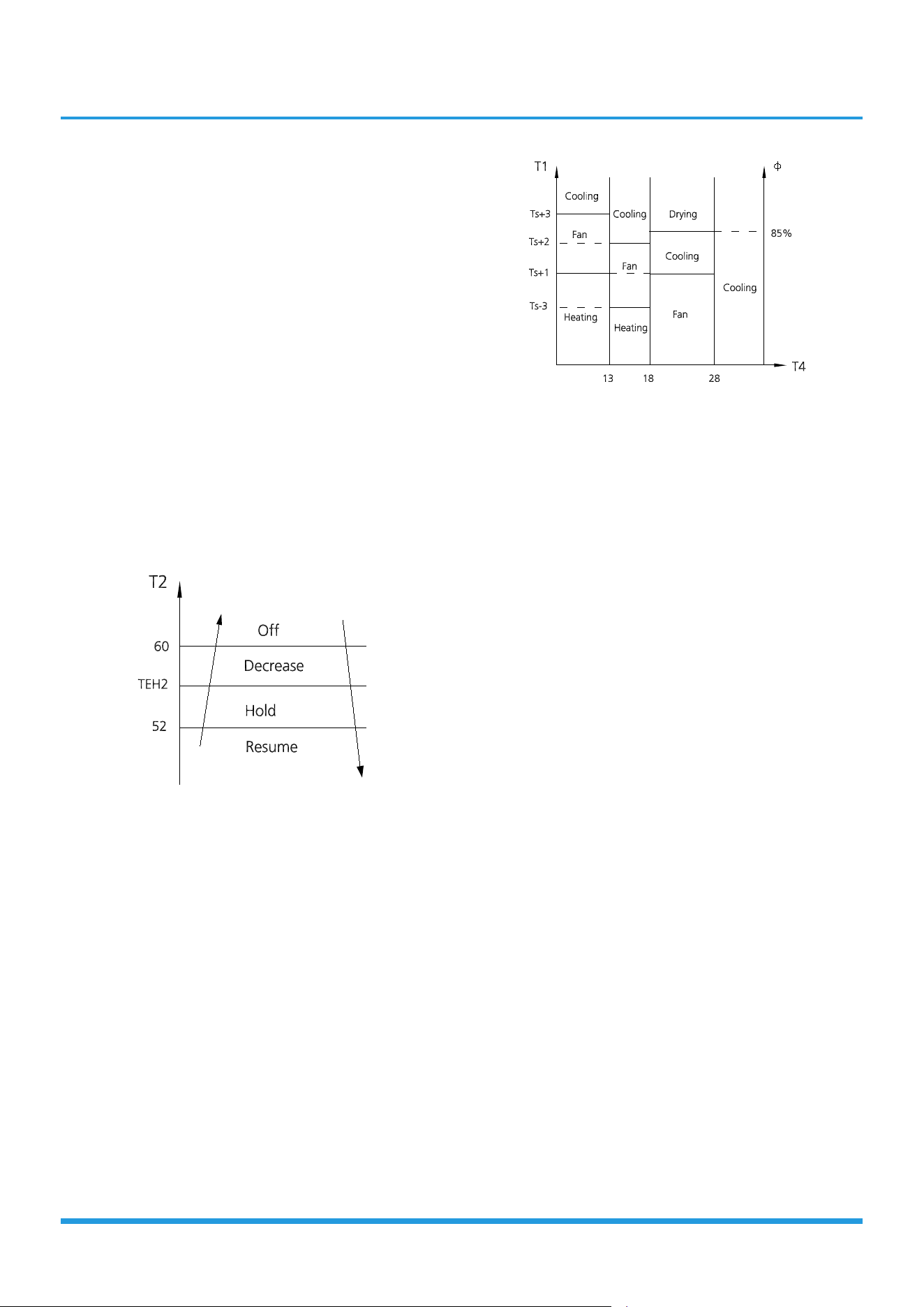
3.4.5 Evaporator Temperature Protection
• Off: Compressor stops.
• Decrease: Decrease the running frequency to the lower
level per 20 seconds.
• Hold: Keep the current frequency.
• Resume: No limitation for frequency.
3.5 Auto-mode
• This mode can be selected with the remote controller
and the setting temperature can be changed between
16°C~30°C(60°F~86°F).
• In auto mode, the machine selects cooling, heating,
auto-drying or fan-only mode on the basis of T1,Ts, T4
and relative humidity.
• If the setting temperature is modified, the machine
selects a new running function.
3.6 Drying mode
• In drying mode, AC operates the same as auto fan in
cooling mode.
• All protections are activated and operate the same as
they do that in cooling mode.
• Low Room Temperature Protection
If the room temperature is lower than 10°C(50°F), the
compressor ceases operations and does not resume until
room temperature exceeds 12°C(53.6°F).
3.7 Forced operation function
• Forced cooling mode:
The compressor and outdoor fan continue to run(fixed at
rated frequency), and the indoor fan runs at rated speed.
After running for 30 minutes, the AC will switch to auto
mode with a preset temperature of 24°C(76°F).
• Forced auto mode:
Forced auto mode operates the same as normal auto mode
with a preset temperature of 24°C(76°F).
• The unit exits forced operation when it receives the
following signals:
• Switch on
• Switch off
• Timer on
• Timer off
• Sleep mode
• Follow me
• Changes in:
• mode
• fan speed
• setting temperature

Product Features 8
• Forced defrosting mode:
• Press AUTO/COOL button continuously for 5s
under forced cooling mode to enter this mode.
• Indoor fan will stop, defrosting lamp will light on.
• Quit this mode and turn off the unit when:
• quit normal defrosting
• turn off by RC
• Press AUTO/COOL button continuously for 5s
again
3.8 Timer function
• Timing range is 24 hours.
• Timer on. The machine will turn on automatically
when reaching the setting time.
• Timer off. The machine will turn off automatically
when reaching the setting time.
• Timer on/off. The machine will turn on automatically
when reaching the setting “on” time, and then turn
off automatically when reaching the setting “off”
time.
• Timer off/on. The machine will turn off automatically
when reaching the setting “off” time, and then turn
on automatically when reaching the setting “on” time.
• The timer function will not change the AC current
operation mode. Suppose AC is off now, it will not
start up firstly after setting the “timer off” function.
And when reaching the setting time, the timer LED
will be off and the AC running mode has not been
changed.
• The setting time is relative time.
• The AC will quit the timer function when it has
malfunction
3.9 Sleep function
• The sleep function is available in cooling, heating, or
auto mode.
• The operational process for sleep mode is as follows:
• When cooling, the temperature rises 1°C/1.8°F
(to not higher than 30°C/86°F) every hour. After 2
hours, the temperature stops rising and the indoor
fan is fixed at low speed.
• When heating, the temperature decreases 1°C/
1.8°F(to not lower than 16°C/60.8°F) every hour.
After 2 hours, the temperature stops decreasing
and the indoor fan is fixed at low speed. Anti-cold
wind function takes priority.
• The operating time for sleep mode is 8 hours, after
which, the unit exits this mode.
• The timer setting is available in this mode.
3.10 Auto-Restart function
• The indoor unit has an auto-restart module that
allows the unit to restart automatically. The module
automatically stores the current settings and, in the
case of a sudden power failure, will restore those
setting automatically within 3 minutes after power
returns.
• If there is a power failure while the unit is running, the
compressor starts 3 minutes after the unit restarts. If
the unit was already off before the power failure, the
unit stands by.
3.11 Active Clean function
• The Active Clean Technology washes away dust,
mold, and grease that may cause odors when it
adheres to the heat exchanger by automatically
freezing and then rapidly thawing the frost. The
internal wind wheel then keeps operating to blow-dry
the evaporator, thus preventing the growth of mold
and keeping the inside clean.
• When this function is turned on, the indoor unit
display window appears “CL”, after 20 to 130
minutes, the unit will turn off automatically and cancel
Active Clean function.
3.12 Follow me(Optional)
• If you press “Follow Me” on the remote, the indoor
unit will beep. This indicates the follow me function is
active.
• Once active, the remote control will send a signal
every 3 minutes, with no beeps. The unit automatically
sets the temperature according to the measurements
from the remote control.
• The unit will only change modes if the information
from the remote control makes it necessary, not from
the unit’s temperature setting.
• If the unit does not receive a signal for 7 minutes or
you press “Follow Me,” the function turns off. The
unit regulates temperature based on its own sensor
and settings.
3.13 8°C Heating(Optional)
In heating mode, the temperature can be set to as low
as 8°C, preventing the indoor area from freezing if
unoccupied during severe cold weather.
3.14 Silence (Optional)
Press “Silence” on the remote control to enable the
SILENCE function. While this function is active, the indoor
unit will run at faint breeze(1% fan speed), which reduces
Product Features 9
noise to the lowest possible level.
3.15 ECO function (Optional)
• Used to enter the energy efficient mode.
• Under cooling mode, press ECO button, the
remote controller will adjust the temperature
automatically to 24°C/75.2°F, fan speed of Auto to
save energy (but only if the set temperature is less
than 24°C/75.2°F). If the set temperature is more
than 24°C/75.2°F and 30°C/86°F, press the ECO
button, the fan speed will change to Auto, the set
temperature will remain unchanged.
• When AC receives signals, such as switch off, Turbo
operation , Silence operation , Self clean operation
, Forced cooling operation, mode setting, Sleeping
mode, or adjusting the set temperature to less than
24°C/76°F,it will quit the ECO operation.
• Operation time in ECO mode is 8 hours. After 8 hours
the AC quits this mode.
• When there’s any one temperature sensor in
malfunction, the AC will quit ECO mode .
• Indoor fan will run at auto fan when enter into the
ECO mode .The setting temperature and setting fan
speed can be changed through remote controller
signal.
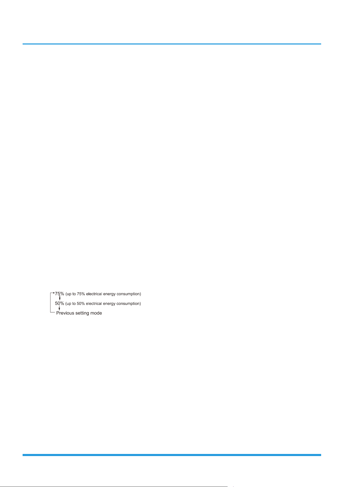
3.16 Electrical energy consumption control
function (Optional)
Press the “Gear” button on remote controller to enter the
energy efficient mode in a sequence of following:
Turn off the unit or activate ECO, sleep, Super cool,
8°C Heating, Silence or self clean function will quit this
function.
3.17 Breeze Away function (Optional)
• This feature avoids direct airflow blowing on the body
and makes you feel indulging in silky coolness.
• NOTE: This feature is available under cooling mode,
fan-only mode and drying mode.
3.18 Wireless Control (Optional)
• Wireless control allows you to control your air
conditioner using your mobile phone and a Wireless
connection.
• For the USB device access, replacement, maintenance
operations must be carried out by professional staff.

Contents
1. First Time Installation Check .................................................................................2
2 Refrigerant Recharge ............................................................................................4
3 Re-Installation .......................................................................................................5
3.1 Indoor Unit ....................................................................................................5
3.2 Outdoor Unit .................................................................................................7
Maintenance
Maintenance 2
1. First Time Installation Check
Air and moisture trapped in the refrigerant system affects
the performance of the air conditioner by:
• Increasing pressure in the system.
• Increasing the operating current.
• Decreasing the cooling or heating efficiency.
• Congesting the capillary tubing due to ice build-up in
the refrigerant circuit.
• Corroding the refrigerant system.
To prevent air and moisture from affecting the air
conditioner’s performance, the indoor unit, as well as the
pipes between the indoor and outdoor unit, must be be
leak tested and evacuated.
Leak test (soap water method)
Use a soft brush to apply soapy water or a neutral liquid
detergent onto the indoor unit connections and outdoor
unit connections. If there is gas leakage, bubbles will form
on the connection.
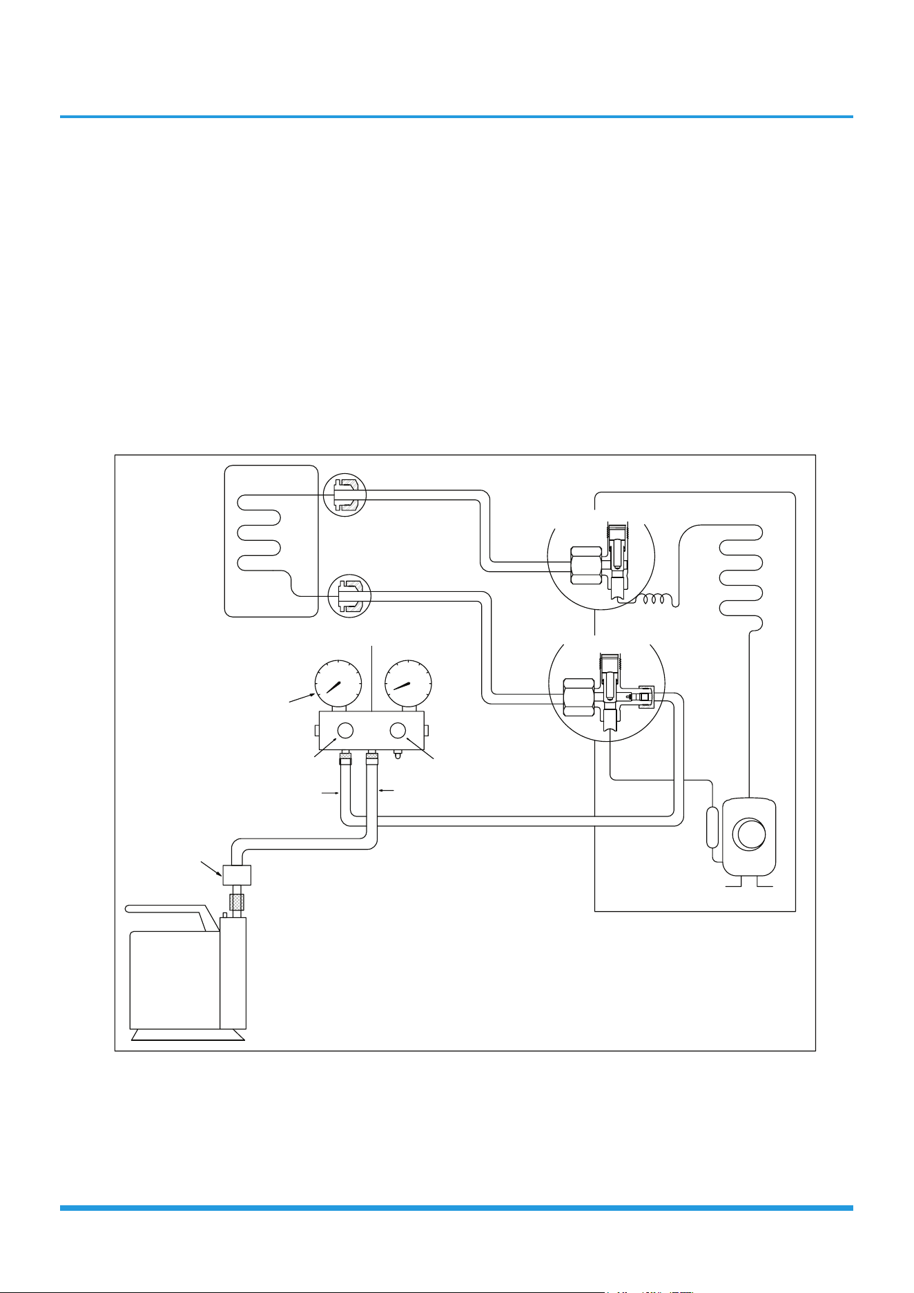
Air purging with vacuum pump
/TJUUX[TOZ
2OW[OJYOJK
-GYYOJK
:]U]G_\GR\K
:NXKK]G_\GR\K
5[ZJUUX[TOZ
)RUYK
)RUYK
3GTOLURJ\GR\K
36G
6XKYY[XK
MG[MK
.GTJRK2U
.GTJRK.O
)NGXMKNUYK
)NGXMKNUYK
<GI[[S
V[SV
<GI[[S
V[SV
)USVU[TJSKZKX
2U
.O

Maintenance 3
Procedure:
1. Tighten the flare nuts of the indoor and outdoor
units, and confirm that both the 2- and 3-way valves
are closed.
2. Connect the charge hose with the push pin of Handle
Lo to the gas service port of the 3-way valve.
3. Connect another charge hose to the vacuum pump.
4. Fully open the Handle Lo manifold valve.
5. Using the vacuum pump, evacuate the system for
30 minutes.
a. Check whether the compound meter indicates
-0.1 MPa (14.5 Psi).
• If the meter does not indicate -0.1 MPa
(14.5 Psi) after 30 minutes, continue
evacuating for an additional 20 minutes.
• If the pressure does not achieve -0.1 MPa
(14.5 Psi) after 50 minutes, check for leakage.
• If the pressure successfully reaches -0.1 MPa
(14.5 Psi), fully close the Handle Lo valve, then
cease vacuum pump operations.
b. Wait for 5 minutes then check whether the gauge
needle moves after turning off the vacuum pump.
If the gauge needle moves backward, check
wether there is gas leakage.
6. Loosen the flare nut of the 3-way valve for 6 or
7 seconds and then tighten the flare nut again.
a. Confirm the pressure display in the pressure
indicator is slightly higher than the atmospheric
pressure.
b. Remove the charge hose from the 3-way valve.
7. Fully open the 2- and 3-way valves and tighten the
cap of the 2- and 3-way valves.
Maintenance 4
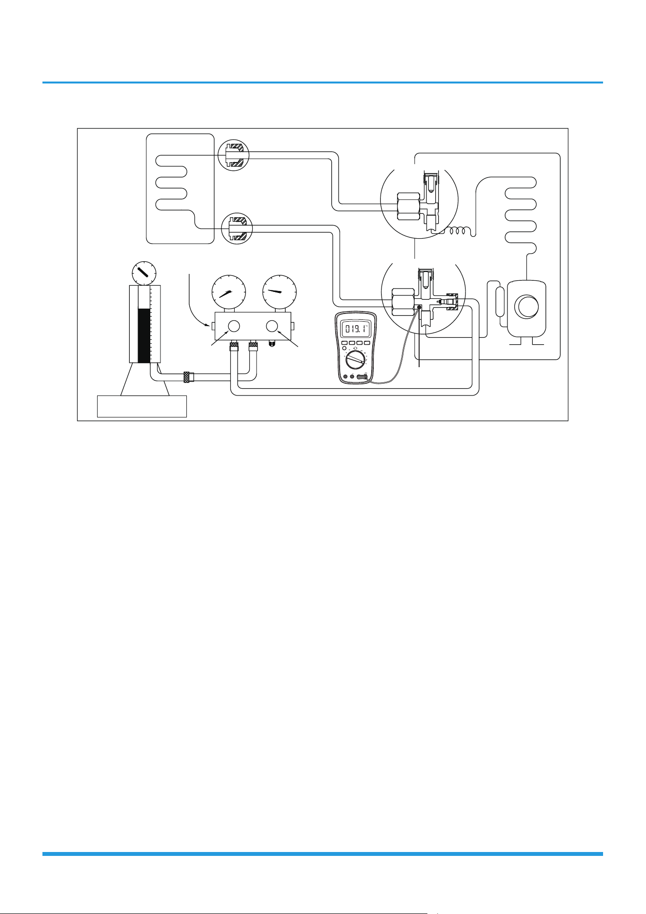
2. Refrigerant Recharge
/TJUUX[TOZ
2OW[OJYOJK
-GYYOJK
)NKIQ\GR\K
56+4
)259+
)NGXMOTM
:]U]G_\GR\K
:NXKK]G_\GR\K
5[ZJUUX[TOZ
5VKT
5VKT
2U
.O
+RKIZXUTOIYIGRK
I_ROTJKX
OFF
A
V
V
mV
A
mA
AmA
A
COM
V
:KSVKXGZ[XK9KTYUX
Procedure:
1. Close both 2- and 3-way valves.
2. Slightly connect the Handle Lo charge hose to the
3-way service port.
3. Connect the charge hose to the valve at the bottom
of the cylinder.
4. If the refrigerant is R410A/R32, invert the cylinder to
ensure a complete liquid charge.
5. Open the valve at the bottom of the cylinder for 5
seconds to purge the air in the charge hose, then fully
tighten the charge hose with push pin Handle Lo to
the service port of 3-way valve..
6. Place the charging cylinder onto an electronic scale
and record the starting weight.
7. Fully open the Handle Lo manifold valve, 2- and
3-way valves.
8. Operate the air conditioner in cooling mode to charge
the system with liquid refrigerant.
9. When the electronic scale displays the correct
weight (refer to the gauge and the pressure of the
low side to confirm, the value of pressure refers to
chapter Appendix), turn off the air conditioner, then
disconnect the charge hose from the 3-way service
port immediately..
10. Mount the caps of service port and 2- and 3-way
valves.
11. Use a torque wrench to tighten the caps to a torque
of 18 N.m.
12. Check for gas leakage.
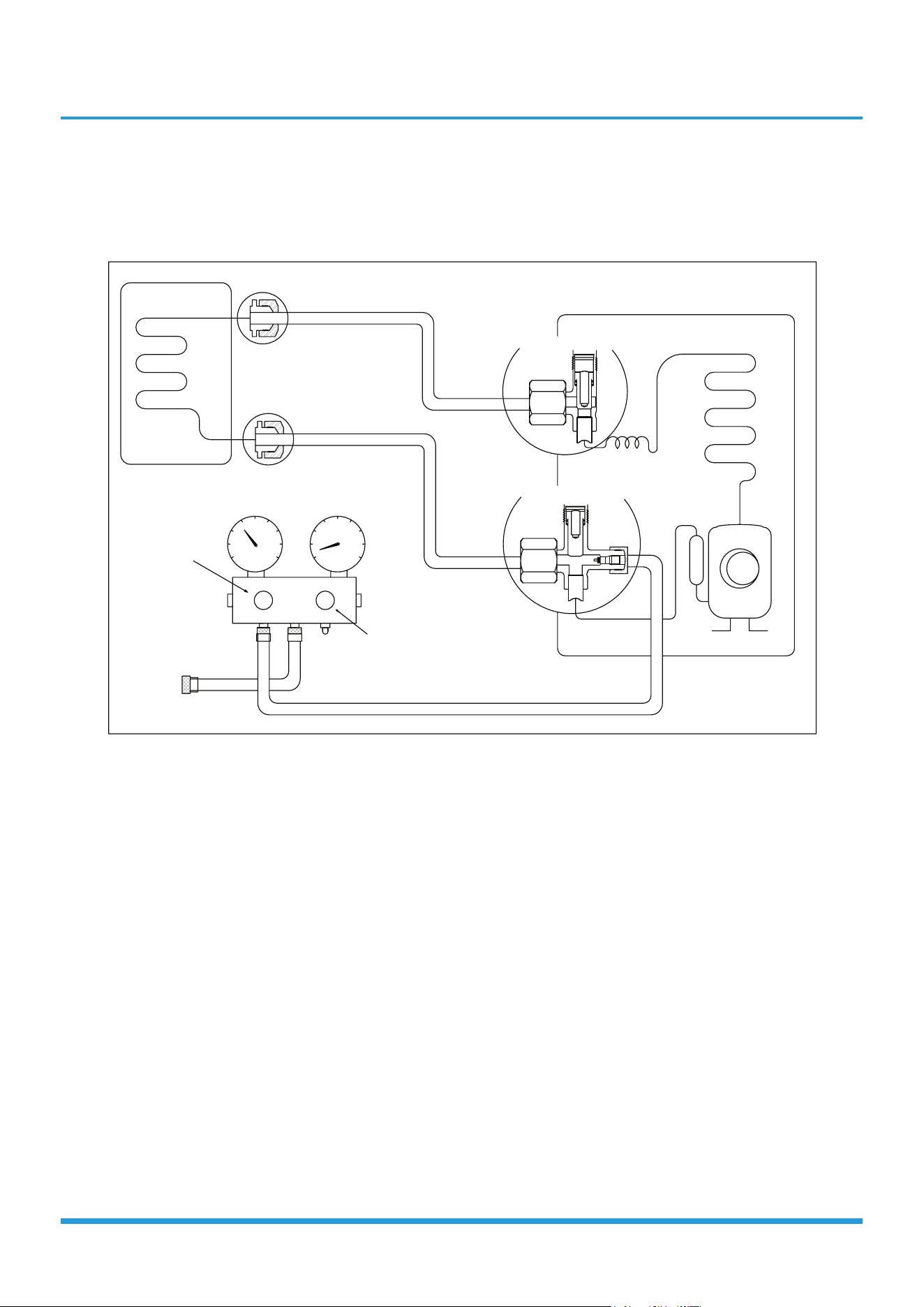
Maintenance 5
3. Re-Installation
3.1 Indoor Unit
Collecting the refrigerant into the outdoor unit
/TJUUX[TOZ
2OW[OJYOJK
-GYYOJK
)RUYK
)RUYK
:]U]G_\GR\K
:NXKK]G_\GR\K
5[ZJUUX[TOZ
5VKT
)RUYK
2U
.O
Procedure:
1. Confirm that the 2- and 3-way valves are opened.
2. Connect the charge hose with the push pin of Handle
Lo to the 3-way valve’s gas service port.
3. Open the Handle Lo manifold valve to purge air
from the charge hose for 5 seconds and then close it
quickly.
4. Close the 2-way valve.
5. Operate the air conditioner in cooling mode. Cease
operations when the gauge reaches 0.1 MPa (14.5
Psi).
6. Close the 3-way valve so that the gauge rests
between 0.3 MPa (43.5 Psi) and 0.5 MPa (72.5 Psi).
7. Disconnect the charge set and mount the caps of
service port and 2- and 3-way valves.
8. Use a torque wrench to tighten the caps to a torque
of 18 N.m.
9. Check for gas leakage.
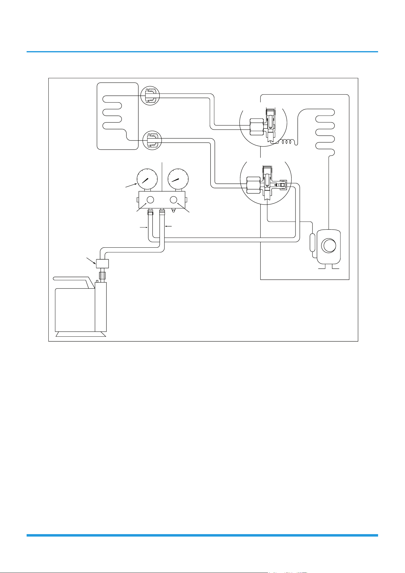
Maintenance 6
Air purging with vacuum pump
/TJUUX[TOZ
2OW[OJYOJK
-GYYOJK
:]U]G_\GR\K
:NXKK]G_\GR\K
5[ZJUUX[TOZ
)RUYK
)RUYK
3GTOLURJ\GR\K
36G
6XKYY[XK
MG[MK
.GTJRK2U
.GTJRK.O
)NGXMKNUYK
)NGXMKNUYK
<GI[[S
V[SV
<GI[[S
V[SV
)USVU[TJSKZKX
2U
.O
Procedure:
1. Tighten the flare nuts of the indoor and outdoor
units, and confirm that both the 2- and 3-way valves
are closed.
2. Connect the charge hose with the push pin of Handle
Lo to the gas service port of the 3-way valve.
3. Connect another charge hose to the vacuum pump.
4. Fully open the Handle Lo manifold valve.
5. Using the vacuum pump, evacuate the system for 30
minutes.
a. Check whether the compound meter indicates
-0.1 MPa (14.5 Psi).
• If the meter does not indicate -0.1 MPa (14.5
Psi) after 30 minutes, continue evacuating for
an additional 20 minutes.
• If the pressure does not achieve -0.1 MPa (14.5
Psi) after 50 minutes, check for leakage.
• If the pressure successfully reaches -0.1 MPa
(14.5 Psi), fully close the Handle Lo valve, then
cease vacuum pump operations.
b. Wait for 5 minutes then check whether the gauge
needle moves after turning off the vacuum pump.
If the gauge needle moves backward, check
wether there is gas leakage.
6. Loosen the flare nut of the 3-way valve for 6 or 7
seconds and then tighten the flare nut again.
a. Confirm the pressure display in the pressure
indicator is slightly higher than the atmospheric
pressure.
b. Remove the charge hose from the 3-way valve.
7. Fully open the 2- and 3-way valves and tighten the
cap of the 2- and 3-way valves.
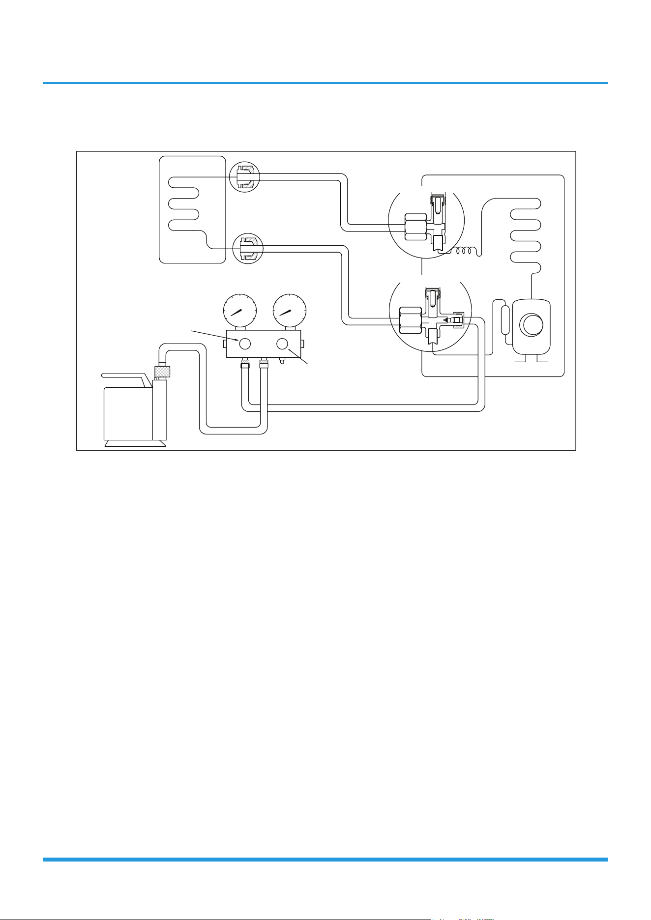
Maintenance 7
3.2 Outdoor Unit
Evacuation for the whole system
/TJUUX[TOZ
2OW[OJYOJK
-GYYOJK
56+4
)259+
:]U]G_\GR\K
:NXKK]G_\GR\K
5[ZJUUX[TOZ
5VKT
5VKT
2U
.O
<GI[[SV[SV
Procedure:
1. Confirm that the 2- and 3-way valves are opened.
2. Connect the vacuum pump to the 3-way valve’s
service port.
3. Evacuate the system for approximately one hour.
Confirm that the compound meter indicates
-0.1 MPa (14.5Psi).
4. Close the valve (Low side) on the charge set and turn
off the vacuum pump.
5. Wait for 5 minutes then check whether the gauge
needle moves after turning off the vacuum pump. If
the gauge needle moves backward, check whether
there is gas leakage.
6. Disconnect the charge hose from the vacuum pump.
7. Mount the caps of service port and 2- and 3-way
valves.
8. Use a torque wrench to tighten the caps to a torque
of 18 N.m.
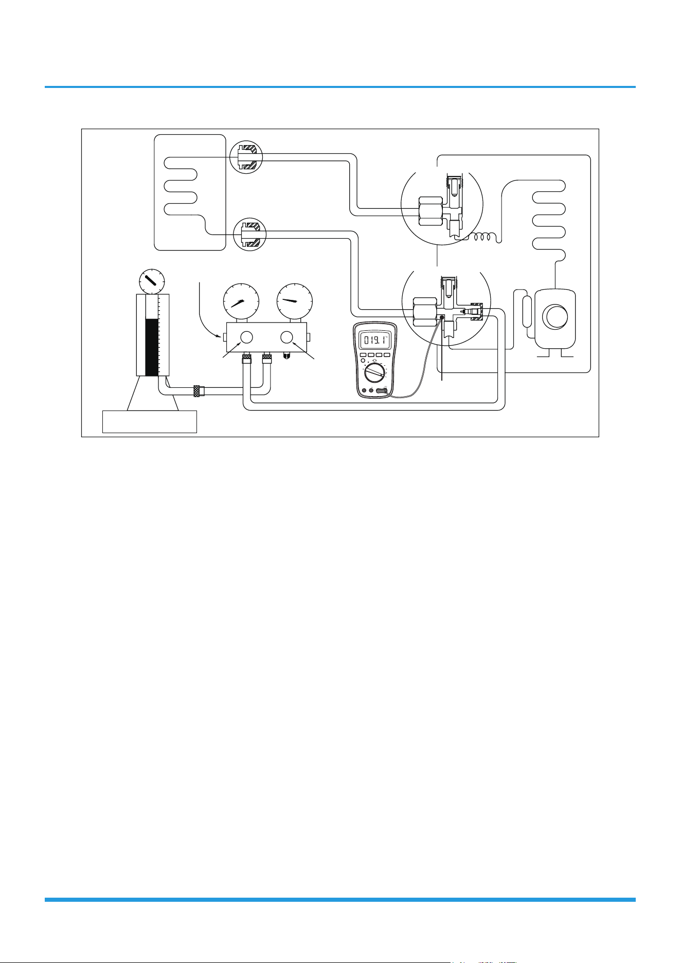
Maintenance 8
Refrigerant charging
/TJUUX[TOZ
2OW[OJYOJK
-GYYOJK
)NKIQ\GR\K
56+4
)259+
)NGXMOTM
:]U]G_\GR\K
:NXKK]G_\GR\K
5[ZJUUX[TOZ
5VKT
5VKT
2U
.O
+RKIZXUTOIYIGRK
I_ROTJKX
OFF
A
V
V
mV
A
mA
AmA
A
COM
V
:KSVKXGZ[XK9KTYUX
Note: 1. Mechanical connectors used indoors shall comply with local regulations.
2. When mechanical connectors are reused indoors, sealing parts shall be renewed. When flared joints
are reused indoors, the flare part shall be re-fabricated.
Procedure:
1. Close both 2- and 3-way valves.
2. Slightly connect the Handle Lo charge hose to the
3-way service port.
3. Connect the charge hose to the valve at the bottom
of the cylinder.
4. If the refrigerant is R410A/R32, invert the cylinder to
ensure a complete liquid charge.
5. Open the valve at the bottom of the cylinder for 5
seconds to purge the air in the charge hose, then fully
tighten the charge hose with push pin Handle Lo to
the service port of 3-way valve..
6. Place the charging cylinder onto an electronic scale
and record the starting weight.
7. Fully open the Handle Lo manifold valve, 2- and
3-way valves.
8. Operate the air conditioner in cooling mode to charge
the system with liquid refrigerant.
9. When the electronic scale displays the correct
weight (refer to the gauge and the pressure of the
low side to confirm, the value of pressure refers to
chapter Appendix), turn off the air conditioner, then
disconnect the charge hose from the 3-way service
port immediately..
10. Mount the caps of service port and 2- and 3-way
valves.
11. Use a torque wrench to tighten the caps to a torque
of 18 N.m.
12. Check for gas leakage.

Contents
1. Safety Caution .......................................................................................................3
2. General Troubleshooting ......................................................................................4
3. Outdoor Unit Point Check Function .....................................................................7
4. Complain Record Form ..........................................................................................8
5. Information Inquiry .............................................................................................10
6. Error Diagnosis and Troubleshooting Without Error Code ...............................15
6.1 Remote maintenance ...................................................................................15
6.2 Field maintenance .......................................................................................16
7. Quick Maintenance by Error Code ......................................................................21
8. Troubleshooting by Error Code ...........................................................................23
TS01-IDU Indoor EEPROM malfunction or indoor EEPROM parameter error diagnosis
and solution
TS01-ODU ODU EEPROM parameter error diagnosis and solution
TS02-S-INV IDU & ODU communication error diagnosis and solution
TS03 Zero-crossing signal detection error diagnosis and solution
TS04-S-IDU IDU fan speed out of control diagnosis and solution
TS04-ODU ODU fan speed out of control diagnosis and solution
TS05-IDU Open circuit or short circuit of temperature sensor(T1, T2) diagnosis and
solution
TS05-ODU Open circuit or short circuit of temperature sensor(T3, T4, TP, T2B,TH)
diagnosis and solution
TS06-INV System lacks refrigerant diagnosis and solution
TS07 IDU main control board and display board communication error diagnosis and
solution
Troubleshooting

Contents
TS08-S: Current overload protection diagnosis and solution
TS05-N10: Refrigerant sensor error or Refrigerant sensor is out of range diagnosis and
solution
TS06-N10: Refrigerant sensor detects leakage or Refrigerant sensor is out of range and
leakage is detected diagnosis and solution
TS09-S ODU IPM module protection diagnosis and solution
TS10-S ODU voltage protection diagnosis and solution
TS11-S-INV Compressor top (or IPM) temp. protection diagnosis and solution
TS12-S Inverter compressor drive error diagnosis and solution
TS26-INV System Pressure protection(low or high pressure) diagnosis and solution
TS14 IDUs mode conflict Diagnosis and Solution
LP Low temperature protection of outdoor uni diagnosis and solution
TS27-INV: High temperature protection of condenser diagnosis and solution
TS30: PFC module protection diagnosis and solution
TS31: Communication error between outdoor main chip and compressor driven chip
diagnosis and solution
TS32: Discharge temperature protection of compressor diagnosis and solution
TS38: Lack phase failure of ODU DC fan motor diagnosis and solution
TS39: ODU compressor lack phase protection diagnosis and solution
TS40: ODU IR chip drive failure diagnosis and solution
8. Check Procedures
Troubleshooting
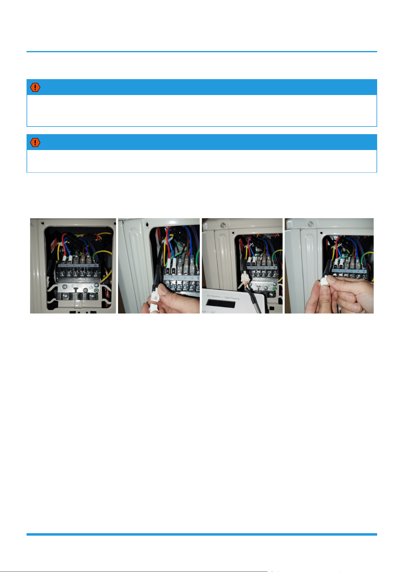
Troubleshooting 3
1. Safety Caution
WARNING
Be sure to turn off all power supplies or disconnect all wires to avoid electric shock.
While checking indoor/outdoor PCB, please equip oneself with antistatic gloves or wrist
strap to avoid damage to the board.
WARNING
Electricity remains in capacitors even when the power supply is off.
Ensure the capacitors are fully discharged before troubleshooting.
NOTE: If using the inverter test tool maintenance, remove the big handle, take out the detection cable, take out female
end of the cable and connect the inverter test tool. After the maintenance is completed, insert the female end back into
the port.
Note: This picture is for reference only. Actual appearance may vary.
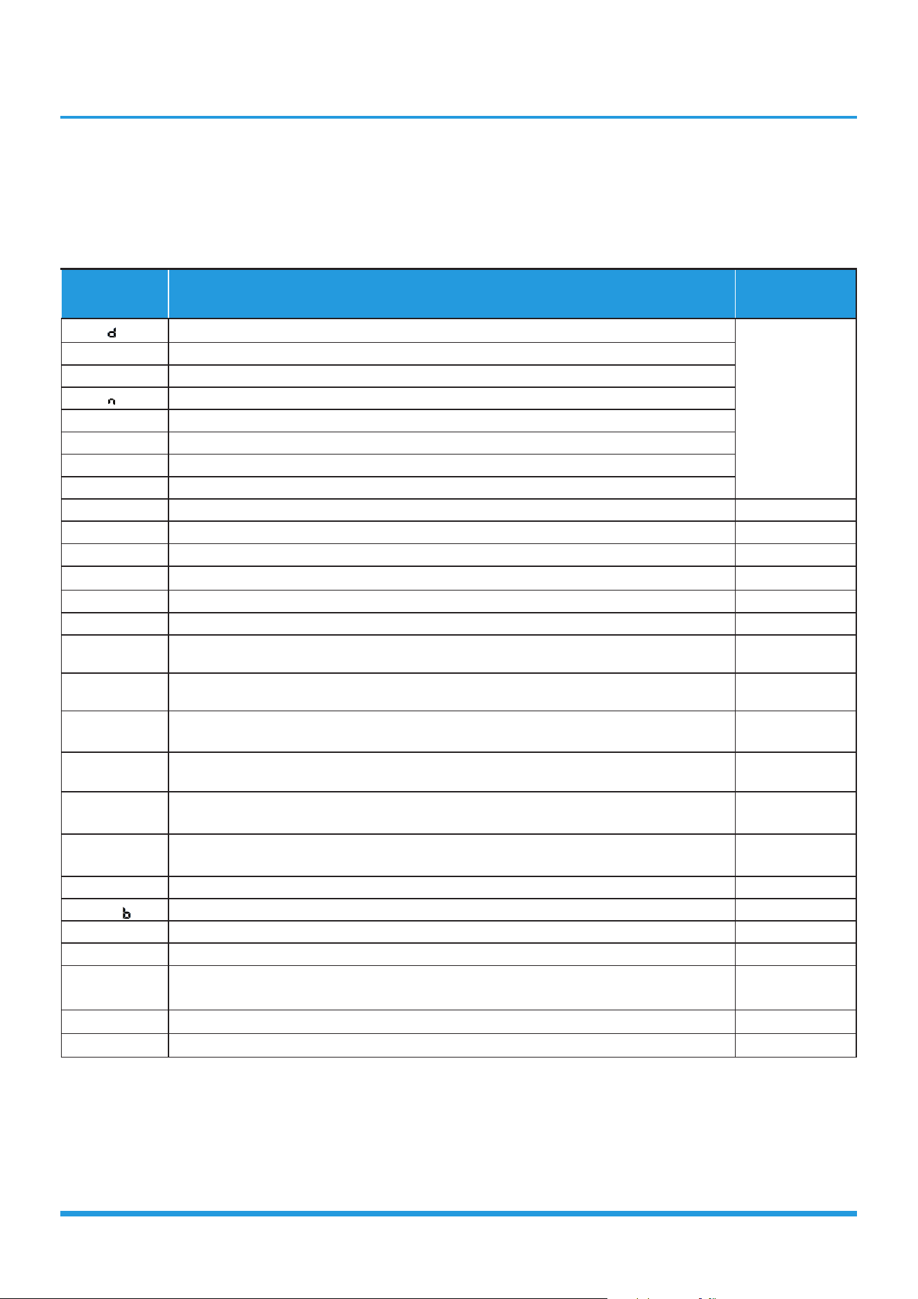
Troubleshooting 4
2. General Troubleshooting
2.1 Error Display (Indoor Unit)
When the indoor unit encounters a recognized error on different models, an error code will be displayed;
These error codes are described in the following tables:
Display Information Solution
F
Defrost
Normal Display,
not error code
CL
Filter cleaning reminder(power on display for 15 seconds)
CL
Active clean
F
Filter replacement reminder(power on display for 15 seconds)(for some models)
FP
Heating in room temperature under 8°C
FC
Forced cooling
AP
AP mode of WIFI connection
CP
Remote switched off
EH 00
IDU EEPROM malfunction TS01-IDU
EH 0A
Indoor EEPROM parameter error TS01-IDU
EL 01
IDU & ODU communication error TS02-S-INV
EH 02
Zero-crossing signal detection error TS03
EH 03
IDU fan speed out of control TS04-S-IDU
EC 51
ODU EEPROM parameter error TS01-ODU
EC 52
ODU coil temp. sensor (T3) error TS05-ODU
EC 53
ODU ambient temp. sensor (T4) error TS05-ODU
EC 54
COMP. discharge temp. sensor (TP) error TS05-ODU
EC 56
IDU coil outlet temp. sensor (T2B) error(Multi-zone) TS05-ODU
EH 60
IDU room temp. sensor (T1) error TS05-IDU
EH 61
IDU pipe temp. (T2) sensor error TS05-IDU
EC 07
ODU fan speed out of control TS04-ODU
EH 0
IDU main control board and display board communication error TS07
FH CC
Refrigerant sensor error TS05-N10
EH C1
Refrigerant sensor detects leakage TS06-N10
EH C2
Refrigerant sensor is out of range and leakage is detected TS06-N10
EH C3
Refrigerant sensor is out of range TS05-N10
EC C1
Other IDU refrigerant sensor detects leakage (Multi-zone) TS06-N10
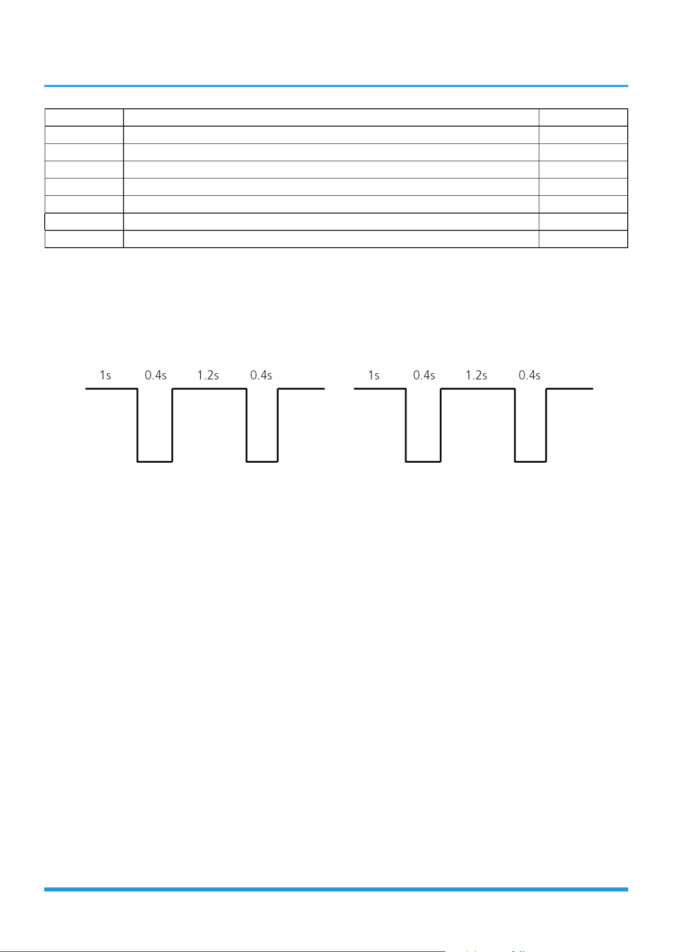
Troubleshooting 5
EL 0C
System lacks refrigerant TS06-INV
PC 00
ODU IPM module protection TS09-S
PC 01
ODU voltage protection TS10-S
PC 02
Compressor top (or IPM) temp. protection TS11-S-INV
PC 04
Inverter compressor drive error TS12-S
PC 03
Pressure protection(low or high pressure)(for some models) TS26-INV
PC 0L
Low ambient temperature protection(for some models) LP
----
IDUs mode conflict(Multi-zone) TS14
For other errors:
The display board may show a garbled code or a code undefined by the service manual. Ensure that this code is not a
temperature reading.
Troubleshooting:
Test the unit using the remote control. If the unit does not respond to the remote, the indoor PCB requires replacement.
If the unit responds, the display board requires replacement.
88 flash frequency:
... ...
Troubleshooting 6
2.2 Error Display (Outdoor Unit with auxiliary board)
Display Malfunction or Protection Solution
F
Defrost
Normal
Display, not
error code
FC
Forced cooling
EC 51
ODU EEPROM parameter error TS01-ODU
EL 01
IDU & ODU communication error TS02-S-INV
PC 40
Communication error between outdoor main chip and compressor driven chip TS31
PC 08
ODU overcurrent protection TS08-S
PC 10
ODU low AC voltage protection TS10-S
PC 11
ODU main control board DC bus high voltage protection TS10-S
PC 12
ODU main control board DC bus low voltage protection/341 MCE error TS10-S
PC 00
ODU IPM module protection TS09-S
PC 0F
PFC module protection TS30
EC 71
Over current failure of ODU DC fan motor TS04-ODU
EC 72
Lack phase failure of ODU DC fan motor TS38
EC 07
ODU fan speed out of control TS04-ODU
PC 43
ODU compressor lack phase protection TS39
PC 44
ODU zero speed protection TS08-S
PC 45
ODU IR chip drive failure TS40
PC 46
Compressor speed has been out of control TS08-S
PC 49
Compressor overcurrent failure TS08-S
PC 30
System high pressure protection TS26-INV
PC 31
System low pressure protection TS26-INV
PC 0A
High temperature protection of condenser TS27-INV
PC 06
Discharge temperature protection of compressor TS32
LC 06
High temperature protection of Inverter module (IPM) TS11-S-INV
PC 02
Compressor top (or IPM) temp. protection TS11-S-INV
PH 90
High temperature protection of evaporator --
PH 91
Low temperature protection of evaporator --
EC 52
ODU coil temp. sensor (T3) error TS05-ODU
EC 53
ODU ambient temp. sensor (T4) error TS05-ODU
EC 54
COMP. discharge temp. sensor (TP) error TS05-ODU
EC 50
Open or short circuit of outdoor unit temperature sensor(T3,T4.TP) TS05-ODU
PC 0L
Low ambient temperature protection(for some models) LP
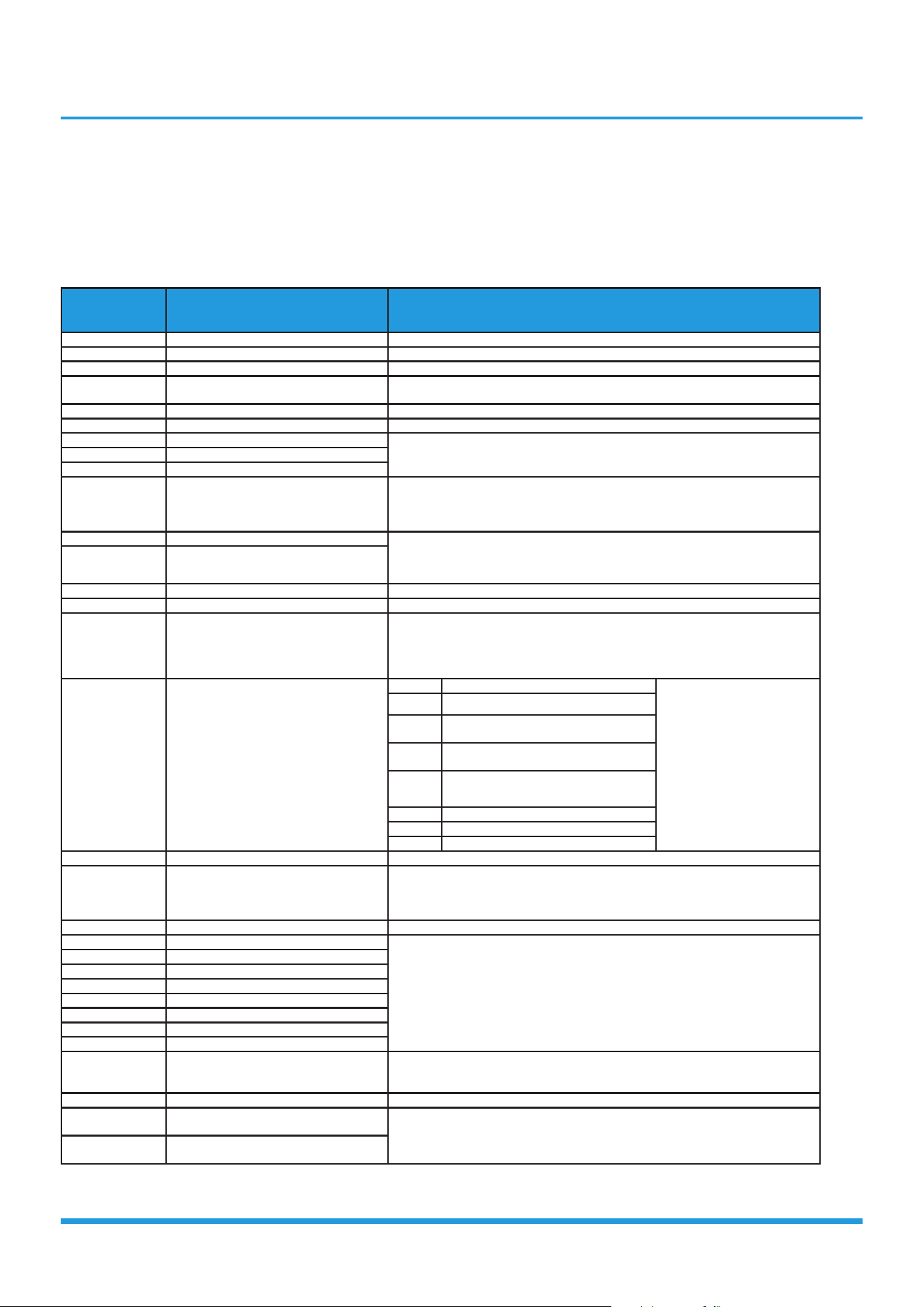
Troubleshooting 7
3. Outdoor Unit Point Check Function
• A check switch is included on the auxiliary board.
• Push SW1 to check the unit’s status while running. The digital display shows the following codes each time the SW1
is pushed.
Number of
Presses
Display Remark
00 Normal display Display running frequency, running state or malfunction code
01 Indoor unit capacity demand code S communication models display “--”
02 Amendatory capacity demand code
03
The frequency after the capacity
requirement transfer
04 The frequency after the frequency limit
05 The frequency of sending to 341 chip
06 Indoor unit evaporator temperature
If the temp. is lower than -9 degree, the digital display tube will show “-9”.If the temp.
is higher than 70 degree, the digital display tube will show “70”.
07 Condenser pipe temp.(T3)
08 Outdoor ambient temp.(T4)
09 Compressor discharge temp.(TP)
The display value is between 0~199
o
C. If the temp. is lower than 0
o
C, the digital display
tube will show “0”.If the temp. is higher than 99
o
C,light the decimal point of the high
digit tube. (For example, the digital display tube show “0.5”,so 0.5 multipled by 10 to
become 5, then added to 100 to become 105
o
C.)
10 AD value of current The display value is hex number.
For example, the digital display tube shows “Cd”, so C*161+d*160=12*16+13=205, it
means AD value is 205.
11 AD value of voltage
12 Indoor unit running mode code Standby:0,Cooling:1, Heating:2, Fan only: 3, Drying:4, Forced cooling:6, Defrosting:7
13 Outdoor unit running mode code Standby:0,Cooling:1, Heating:2, Fan only: 3, Drying:4, Forced cooling:6, Defrosting:7
14 EXV open angle
Actual data/4.
If the value is higher than 99, light the decimal point of the high digit tube. For
example, the digital display tube show “2.0”,so 2.0 multipled by 10 to become 20,
then added to 100 to become 120,it means the EXV open angle is 120×4=480p.)
15 Frequency limit symbol
Bit7 Frequency limit caused by IGBT radiator The display value is hex
number. For example, the
digital display tube show 2A,
the corresponding binary is
101010, so Bit5=1, Bit3=1, and
Bit1=1
It means frequency limit caused
by T2, T3 and current.
Bit6 Frequency limit caused by PFC
Bit5
Frequency limit caused by high
temperature of T2.
Bit4
Frequency limit caused by low
temperature of T2.
Bit3 Frequency limit caused by T3.
Bit2 Frequency limit caused by TP.
Bit1 Frequency limit caused by current
Bit0 Frequency limit caused by voltage
16 DC fan motor speed 0:off 1:Turbo 2:High 3:Medium 4:Low 5: Breeze 6: Super breeze 7:other
17 IGBT radiator temp.
The display value is between 0~130 degree. If the temp. is lower than 0
o
C, the digital
display tube will show “0”.If the temp. is higher than 99 degree, light the decimal
point of the high digit tube. (For example, the digital display tube show “0.5”,so 0.5
multipled by 10 to become 5, then added to 100 to become 105
o
C.)
18 Indoor unit number The indoor unit can communicate with outdoor unit well.
19 Evaporator pipe temp. T2 of 1# indoor unit
S communication models display “--”
20 Evaporator pipe temp. T2 of 2# indoor unit
21 Evaporator pipe temp. T2 of 3# indoor unit
22 1# Indoor unit capacity demand code
23 2# Indoor unit capacity demand code
24 3# Indoor unit capacity demand code
25 Room temp. T1 of 1# indoor unit
26 Room temp. T1 of 2# indoor unit
27 Average room temp. T1
If the temp. is lower than 0 degree, the digital display tube will show “0”.If the temp. is
higher than 70 degree, the digital display tube will show “70”. If the indoor unit is not
connected, the digital display tube will show: “--”
28 Reason of stop
29
Evaporator pipe temp. T2B of 1# indoor
unit
S communication models display “--”
30
Evaporator pipe temp. T2B of 2# indoor
unit
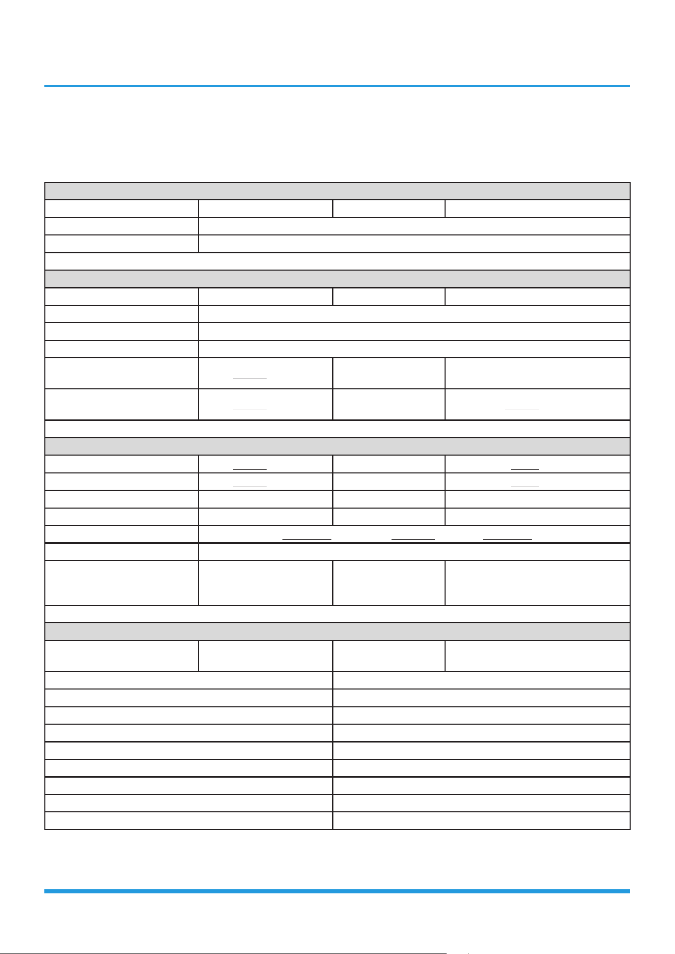
Troubleshooting 8
4. Complain Record Form
Complain Record Form
Request No.: Date:
Installation Date: Service Date:
Customer Information
Name Telephone No.
Home Address
Email
Product Information
Indoor Unit Model Outdoor Unit Model
Serial No. of indoor unit
Serial No. of outdoor unit
Working Mode □Cooling □Heating □Fan only □Dry
Setting temperature °C / °F Fan speed
□Turbo □High □Medium □Low
□Auto
Temperature of air inlet °C / °F
Temperature of air
outlet
°C / °F
Installation / Condition Information
Indoor temperature °C / °F Indoor humidity %RH
Outdoor temperature °C / °F Outdoor humidity %RH
Length of Connecting pipe Pipe diameter Gas pipe: Liquid pipe:
Length of Wiring wire diameter
System Running Pressure MPa or Bar or PSI
Room size (L*W*H)
Photo of Installation of In-
door unit
(Photo #1)
Photo of Installation
of Outdoor unit
(Photo #2)
Failure Description
Error Code of Indoor unit
Code of Outdoor
PCB
Unit does not start
Remote control does not work
Indoor display shows nothing
No cooling or heating at all
Less cooling or heating
Unit starts but stops shortly
High noise
High vibration
Troubleshooting 9
Parameter Checking information by Remote controller
Displaying code Displaying code meaning Display value Display value meaning
T1 Room temperature
T2 Indoor coil temperature
T3 Outdoor coil temperature
T4 Ambient temperature
TP Discharge temperature
FT Targeted Frequency
Fr Actual Frequency
dL Compressor current
Uo Outdoor AC voltage
Sn Indoor capacity test / N/A
-- Reserve / N/A
Pr Outdoor fan speed
Lr EXV opening steps
ir Indoor fan speed
HU Indoor humidity
TT
Adjusted setting
temperature
DT Reserve / N/A
iF Reserve / N/A
nA Reserve / N/A
oT GA algorithm frequency
Approval from Manufacturer
□Approved
□More Proof needed
□Rejected

Troubleshooting 10
5. Information Inquiry&Setting
• To enter engineer mode, in power-on or standby mode, and in non-locked state, press the key combination “ON/OFF
+ Air Speed” for 7s:
• After entering the engineer mode, the remote control will display icons of “Auto, Cool, Dry, Heat”, and the Battery
icon; at the same time, it will also display the numeric code of the current engineer mode (for the initial engineer
mode, the numeric code displayed is 0), and all other icons are inactive.
• In engineer mode, the value of the current numeric code can be adjusted circularly through the Up/Down key, with
the setting range of 0 to 30. Each time the current numeric code is adjusted, the special code of the engineer mode
will be transmitted with a delay of 0.6s. The code can also be transmitted by pressing “OK”, and the special code of
the engineer mode sent contains information of the currently displayed numeric code (if the numeric code is 0, the
code to enter the engineer mode will be transmitted).
• In engineer mode, other keys or operations are invalid except for the On/Off key, the Up/Down key, the OK key or
executing the operation to exit the engineer mode.
Code Query Content Advanced Function Setting
0 Error code
press “On/Off” for 2s to enter the Capactity, the code displayed is “Ch”, press
“OK” to send the Query Capactity code; press the Up/Down key to select 1 to
100K
1 T1 temperature
press "On/Off" for 2s to enter the Power Down Memory Selector, the code
displayed is “Ch”, press "OK" to send the Query Power Down Memory
Selector code; press the Up/Down key to select 1 or 0 and press “OK” to
confirm, 1 indicates that the power down memory exists, and 0 indicates that
no power down memory exists; and press "On/Off" for 2s to exit. (Set within
1 minute after power on)
2 T2 temperature
press "On/Off" for 2s to enter the Internal Fan Control Selector after the
pre-set temperature is reaches, the code displayed is “Ch”, press "OK" to
send the Query Internal Fan Control Selector code; press the Up/Down key to
select 1 to 13: 1 - Stop the fan, 2 - Min. fan speed, 3 - Set the air speed, 4 -
Termal stop for 4min running for 1min, 5 - Termal stop for 8min running for
1min, 6 - Termal stop for 16min running for 1min, 7 - Termal stop for 24min
running for 1min, 8 - Termal stop for 48min running for 1min, 9 - Termal stop
for 15min running for 2.5min, 10 - Termal stop for 30min running for 2.5min,
11 - Termal stop for 60min running for 2.5min, 12- Set fan speed(but stop the
fan when the set fan speed is auto fan) and 13- Breeze fan(but stop the fan
when the set fan speed is auto fan) press "OK" to confirm, and press "On/
Off" for 2s to exit.(Item 5~13 are valid for some models)(Set within 1 minute
after power on)
3 T3 temperature
press "On/Off" for 2s to enter the Mode Selector, press the Up/Down key to
select CH (cool and heat, Auto + Cool + Dry + Heat + Fan), HH (Heat only,
Heat only + Fan), CC(Cool only, Auto + Cool + Dry + Fa) or nU (Cool and
Heat without Auto, Cool + Dry + Heat + Fan), press "OK" to confirm, and the
mode selected can be memorized when the remote control is powered down
and powered on; and press "On/Off" for 2s to exit. When the remote control
does not burn any parameters, the mode setting will not be memorized.(CC or
nU is valid for some models)(Set within 1 minute after power on)
4 T4 temperature
press the "On/Off" for 2s to enter the Min. Set Temperature Selector, press
the Up/Down key to select "16°C~24°C", press "OK" to confirm, and the
Min. Set Temperature can be memorized when the remote control is powered
on and power lost; and press "On/Off" for 2s to exit. When the remote
control does not burn any parameters, the min. set temperature will not be
memorized.(Set within 1 minute after power on)
Troubleshooting 11
5 TP temperature
press "On/Off" for 2s to enter the Max. Set Temperature Selector, press the
Up/Down key to select "25°C~30°C", press "OK" to confirm, and the Max.
Set Temperature can be memorized when the remote control is powered
on and power lost; and press "On/Off" for 2s to exit. When the remote
control does not burn any parameters, the max. set temperature will not be
memorized.(Set within 1 minute after power on)
6
Compressor
Target Frequency
FT
press "On/Off" for 2s to enter the Multi-split Cooling and Heating Preference
Selector, the code displayed is “Ch”, press "OK" to send the Query Multi-
split Cooling and Heating Preference Selector code; press the Up/Down key to
select H (heating preferred), C (cooling preferred) or A (master settings), press
"OK" to confirm; and press "On/Off" for 2s to exit.(Set within 1 minute after
power on)(Only multi models are effective)
7
Compressor
Running
Frequency Fr
/
8 /
9
Current AC
Voltage Uo
/
10 /
11
press "On/Off" for 2S to enter the Min. Desired Cooling Frequency Selector,
the code displayed is Ch, press "OK" to send the Query Min. Desired Cooling
Frequency Selector code; press the Up/Down key to select the minimum
cooling frequency desired and press "OK" to confirm; press "On/Off" for 2s to
exit.(Range:10-50Hz,--;”--” cancels the Settings)(for some models) (Set within
1 minute after power on)
12
Set Speed Pr of
the outdoor fan
press "On/Off" for 2s to enter the Min. Desired Heating Frequency Selector,
the code displayed is “Ch”, press "OK" to send the Query Min. Desired
Heating Frequency Selector code; press the Up/Down key to select the min.
desired heating frequency value, press "OK" to confirm; and press the "On/
Off" for 2s to exit.(Range:10-50Hz,--;”--” cancels the Settings) (for some
models)(Set within 1 minute after power on)
13 Opening Lr of EEV
press "On/Off" for 2s to enter the Max. Running Frequency Selector of the
restricted area 6 in the cooling mode T4, the code displayed is “Ch”, press
"OK" to send the Query Max. Running Frequency Selector code of the
restricted area 6 in the cooling mode T4; press the Up/Down key to select
the limit, then press "OK" to confirm; and press "On/Off" for 2s to exit.
(Range:20-150Hz,--;”--” cancels the Settings)(for some models)
14
Actual Running
Speed ir of the
indoor fan
press “On/Off” for 2s to enter the Resonance Point Frequency Selector, the
code displayed is “Ch”, press “OK” to send the Resonance Point Frequency
Selector code; press the Up/Down key to select the outdoor forced running
frequency(“10-250Hz“), then press “OK” to confirm; and press “On/Off” for
2s to exit.(Range:10-250Hz,--;”--” cancels the Settings)(for some models)
15
Indoor Humidity
Hu
press "On/Off" for 2s to enter the Outdoor Forced Running Frequency
Selector, the code displayed is “Ch”, press "OK" to send the Query Outdoor
Forced Running Frequency Selector code; press the Up/Down key to select
the outdoor forced running frequency(“10-250Hz“), then press "OK" to
confirm; and press "On/Off" for 2s to exit.(Range:10-250Hz,--;”--” cancels the
Settings)(for some models)
16
Set Temperature
TT after
compensation
press "On/Off" for 2s to enter One-Key Recovery, the code displayed is “rS”,
then press "OK" to send the One-Key Recovery code, the mode selector of the
remote control will recover to "Cooling and heating", the min. temperature
recovers to 16°C, and the max. temperature recovers to 30°C; and press "On/
Off" for 2s to exit.(for some models)
Troubleshooting 12
17 / /
18
WIFI signal
strength
press “On/Off” for 2s to enter Model Selection the code displayed is “Ch”,
then press “OK” to send the Model Selection code, press the Up/Down key to
select,such as 23,26,32,35,51,72,120 etc; and press “On/Off” for 2s to exit.
19
Dc bus voltage
AD value
press "On/Off" for 2s to enter the Cooling Frequency Threshold Settings; press
the Up/Down key to select the cooling frequency threshold, press "OK" to
confirm; and press the "On/Off" for 2s to exit. (Range:40,41……83,84,--;”--”
cancels the Settings)(Set within 1 minute after power on)
20
Indoor Target
Frequency oT
press "ON/OFF" for 2s to enter the Heating Frequency Threshold Settings;
press the Up/Down key to select the heating frequency threshold, press "OK"
to confirm; and press "On/Off" for 2s to exit.(Range:40,41……83,84,--;”--”
cancels the Settings) (Set within 1 minute after power on)
21
Reserve
press "On/Off" for 2s to enter the Cooling Temperature Compensation Value
Settings, the code displayed is “Ch”, then press "OK" to send the Query
Cooling Temperature Compensation Value code; press the Up/Down key to
select the cooling temperature compensation value, then press "OK"; and
press "On/Off" for 2s to exit.(Range:-3.0,-2.5,-2.0…2.0,2.5,3.0,3.5,--;”--”
cancels the Settings)
22
press "On/Off" for 2s to enter the Heating Temperature Compensation Value
Settings, the code displayed is “Ch”, press "OK" to send the Query Heating
Temperature Compensation Value code; press the Up/Down key to select
the heating temperature compensation value, then press "OK"; and press
"On/Off" for 2s to exit.(Range:-6.5,-6,…1.0,1.5,2.0…6.0,6.5,7.0,7.5,--;”--”
cancels the Settings)
23
press "On/Off" for 2s to enter the Max. Cooling Air Speed Settings, the code
displayed is “Ch”, press "OK" to send the Query Max. Cooling Air Speed
code; press the Up/Down key to select the max. cooling air speed, then press
"OK"; and press "On/Off" for 2s to exit.(Range: -41,-40,-39…17,18,19,20,--
;”--” cancels the Settings)
24
press "On/Off" for 2S to enter the Min. Cooling Air Speed Settings, the code
displayed is "Ch", press "OK" to send the Query Min. Cooling Air Speed
code; press the Up/Down key to select the minimum cooling air speed and
press "OK" to confirm; press "On/Off" for 2s to exit.(Range: -41,-40,-39…
17,18,19,20,--;”--” cancels the Settings)
25
press "On/Off" for 2s to enter the Max. Heating Air Speed Settings, the code
displayed is "Ch", press "OK" to send the Query Max. Heating Air Speed
code; press the Up/Down key to select the maximum heating air speed and
press "OK" to confirm; press "On/Off" for 2s to exit.(Range: -41,-40,-39…
17,18,19,20,--;”--” cancels the Settings)
26
press "On/Off" for 2s to enter the Min. Heating Air Speed Settings, the code
displayed is "Ch", press "OK" to send the Query Min. Heating Air Speed
code; press the Up/Down key to select the minimum heating air speed and
press "OK" to confirm; press "On/Off" for 2s to exit.(Range: -41,-40,-39…
17,18,19,20,--;”--” cancels the Settings)
27
/
28
press “On/Off” for 2s to enter the The Temperature of Stop Fan, the code
displayed is “Ch”, press “OK” to send the The Temperature of Stop Fan code;
press the Up/Down key to select 16,17,18...28 and press “OK” to confirm;
press “On/Off” for 2s to exit.
29
30
Troubleshooting 13
• In Channel 1~30 settings of the engineer mode, long press the On/off key to return the previous engineer mode.
• When the setting is successful, “CS” will be displayed;When the setting fails, “CF “will be displayed.
Exit of engineer mode:
1)In engineer mode, press the key combination of “On/Off + Air speed” for 2s;
2)The engineer mode will be exited if there are no valid key operations for continuous 60s.
Error code of engineer mode
Display Error Information
A
No fault or protection
EH 00
IDU EEPROM malfunction
EH 0A
Indoor EEPROM parameter error
EL 01
IDU & ODU communication error
EH A
Communication error between indoor unit and indoor external fan module
EH 30
Parameters error of indoor external fan
EH 35
Phase failure of indoor external fan
EH 36
Indoor external fan current sampling bias fault
EH 37
Indoor external fan zero speed failure
EH 38
Indoor external fan stall failure
EH 39
Out of step failure of indoor external fan
EH 3A
Low voltage protection of indoor external fan DC bus
EH 3
Indoor external fan DC bus voltage is too high fault
EH 3E
Indoor external fan overcurrent fault
EH 3F
Indoor external fan module protection/hardware overcurrent protection
EH 03
IDU fan speed out of control
EC 51
ODU EEPROM parameter error
EC 52
ODU coil temp. sensor (T3) error
EC 53
ODU ambient temp. sensor (T4) error
EC 54
COMP. discharge temp. sensor (TP) error
EC 55
ODU IPM module temp.sensor(TH) error
EC 0
Outdoor unit malfunction
Eh 60
IDU room temp. sensor (T1) error
Eh 61
Evaporator coil temperature sensor T2 is in open circuit or short circuit
EC 71
Outdoor external fan overcurrent fault
ec 75
Outdoor external fan module protection/hardware overcurrent protection
ec 72
Outdoor external fan phase failure
ec 74
Outdoor external fan current sampling bias fault
ec 73
Zero speed failure of outdoor unit DC fan
EC 07
ODU fan speed out of control(
EL 0C
System lacks refrigerant
Troubleshooting 14
PC 00
ODU IPM module protection
PC 10
ODU low AC voltage protection
PC 11
ODU main control board DC bus high voltage protection
PC 12
ODU main control board DC bus low voltage protection/341 MCE error
pc 02
Compressor top (or IPM) temp. protection
PC 40
Communication error between outdoor main chip and compressor driven chip
Pc 41
Compressor current sampling circuit failure
PC 42
Compressor start failure of outdoor unit
PC 43
ODU compressor lack phase protection
PC 44
ODU zero speed protection
PC 45
ODU IR chip drive failure
PC 46
Compressor speed has been out of control
PC 49
Compressor overcurrent failure
PC 06
Discharge temperature protection of compressor
PC 08
ODU Current protection
PH 09
Anti-cold air in heating mode
pc 0f
PFC module protection
pc 30
System overpressure protection
pc 31
System pressure is too low protection
PC 03
Pressure protection(low or high pressure)
pc 0l
Outdoor low temp. protection
PH 90
High temperature protection of evaporator
PH 91
Low temperature protection of evaporator
PC 0A
High temperature protection of condenser
ph 0c
Indoor unit humidity sensor malfunction
LH 00
Evaporator temp. freq.limited(L0)
lh 30
Indoor external fan current freq. limited
lh 31
Indoor external fan voltage freq. limited
LC 01
Condenser coil temp. (T3) freq. limited
LC 02
ODU exhaust temp. (TP) freq. limited
LC 05
Voltage freq. limited
LC 03
Current freq. limited
LC 06
IPM module temp. freq. limited
LC 30
High pressure freq. limited
LC 31
Low pressure freq. limited
LH 07
Remote control frequency limitation in effect
--
IDUs mode conflict(Multi-zone)
Troubleshooting 15
6. Error Diagnosis and Troubleshooting Without Error Code
WARNING
Be sure to turn off unit before any maintenance to prevent damage or injury.
6.1 Remote maintenance
SUGGESTION: When troubles occur, please check the following points with customers before field maintenance.
No. Problem Solution
1 Unit will not start TS17 - TS18
2 The power switch is on but fans will not start TS17 - TS18
3 The temperature on the display board cannot be set TS17 - TS18
4 Unit is on but the wind is not cold(hot) TS17 - TS18
5 Unit runs, but shortly stops TS17 - TS18
6 The unit starts up and stops frequently TS17 - TS18
7 Unit runs continuously but insufficient cooling(heating) TS17 - TS18
8 Cool can not change to heat TS17 - TS18
9 Unit is noisy TS17 - TS18
Troubleshooting 16
6.2 Field maintenance
Problem Solution
1 Unit will not start TS19 - TS20
2 Compressor will not start but fans run TS19 - TS20
3 Compressor and condenser (outdoor) fan will not start TS19 - TS20
4 Evaporator (indoor) fan will not start TS19 - TS20
5 Condenser (Outdoor) fan will not start TS19 - TS20
6 Unit runs, but shortly stops TS19 - TS20
7 Compressor short-cycles due to overload TS19 - TS20
8 High discharge pressure TS19 - TS20
9 Low discharge pressure TS19 - TS20
10 High suction pressure TS19 - TS20
11 Low suction pressure TS19 - TS20
12 Unit runs continuously but insufficient cooling TS19 - TS20
13 Too cool TS19 - TS20
14 Compressor is noisy TS19 - TS20
15 Horizontal louver can not revolve TS19 - TS20
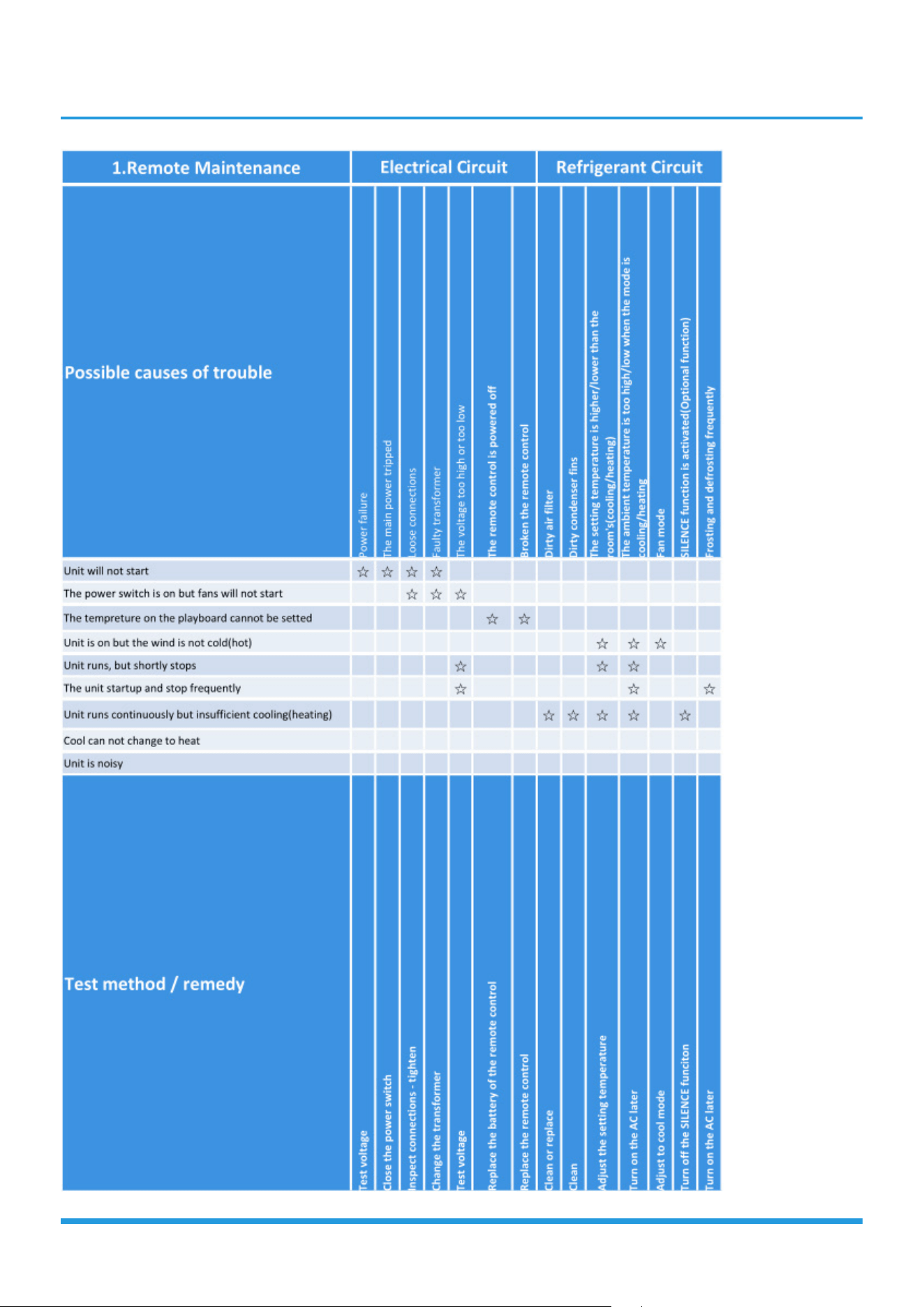
Troubleshooting 17
Troubleshooting 18
1.Remote Maintenance
Possible causes of trouble
Heavy load condition
Loosen hold down bolts and / or screws
Bad airproof
The air inlet or outlet of either unit is blocked
Interference from cell phone towers and remote boosters
Shipping plates remain attached
Unit will not start
The power switch is on but fans will not start
☆
The temperature on the display board cannot be set
Unit is on but the wind is not cold(hot)
Unit runs, but shortly stops
The unit starts up and stops frequently ☆
Unit runs continuously but insufficient cooling(heating)
☆ ☆ ☆
Cool can not change to heat
Unit is noisy ☆
☆
Test method / remedy
Check heat load
Tighten bolts or screws
Close all the windows and doors
Remove the obstacles
Reconnect the power or press
ON/OFF button on remote control to restart operation
Remove them
Others
Troubleshooting 19
2.Field Maintenance
Possible causes of trouble
Compressor stuck
Shortage of refrigerant
Restricted liquid line
Dirty air filter
Dirty evaporator coil
Insufficient air through evaporator coil
Overcharge of refrigerant
Dirty or partially blocked condenser
Air or incompressible gas in refrigerant cycle
Short cycling of condensing air
High temperature condensing medium
Insufficient condensing medium
Broken compressor internal parts
Inefficient compressor
Expansion valve obstructed
Expansion valve or capillary tube closed completely
Leaking power element on expansion valve
Poor installation of feeler bulb
Heavy load condition
Loosen hold down bolts and / or screws
Shipping plates remain attached
Poor choices of capacity
Contact of piping with other piping or external plate
Unit will not start
Compressor will not start but fans run
☆
Compressor and condenser (outdoor) fan will not
start
Evaporator (indoor) fan will not start
Condenser (Outdoor) fan will not start
Unit runs, but shortly stops ☆ ☆
☆ ☆ ☆ ☆
Compressor short-cycles due to overload
☆ ☆ ☆
High discharge pressure ☆ ☆ ☆ ☆ ☆ ☆
Low discharge pressure
☆ ☆
High suction pressure ☆
☆ ☆ ☆
Low suction pressure
☆ ☆ ☆
☆ ☆ ☆ ☆
☆
Unit runs continuously but insufficient cooling
☆ ☆ ☆ ☆ ☆ ☆ ☆ ☆ ☆
☆ ☆
Too cool
Compressor is noisy ☆
☆ ☆ ☆ ☆
Horizontal louver can not revolve
Test method / remedy
Replace the compressor
Leak test
Replace restricted part
Clean or replace
Clean coil
Check fan
Change charged refrigerant volume
Clean condenser or remove obstacle
Purge, evacuate and recharge
Remove obstruction to air flow
Remove obstruction in air or water flow
Remove obstruction in air or water flow
Replace compressor
Test compressor efficiency
Replace valve
Replace valve
Replace valve
Fix feeler bulb
Check heat load
Tighten bolts or screws
Remove them
Choose AC of lager capacity or add the number of AC
Rectify piping so as not to contact each other or with external
plate
Refrigerant Circuit
Others
Troubleshooting 20
2.Field Maintenance
Possible causes of trouble
Power failure
Blown fuse or varistor
Loose connections
Shorted or broken wires
Safety device opens
Faulty thermostat / room temperature sensor
Wrong setting place of temperature sensor
Faulty transformer
Shorted or open capacitor
Faulty magnetic contactor for compressor
Faulty magnetic contactor for fan
Low voltage
Faulty stepping motor
Shorted or grounded compressor
Shorted or grounded fan motor
Unit will not start ☆ ☆ ☆ ☆ ☆ ☆
Compressor will not start but fans run
☆ ☆ ☆ ☆
☆
Compressor and condenser (outdoor) fan will not start ☆ ☆ ☆
Evaporator (indoor) fan will not start
☆ ☆ ☆
☆
Condenser (Outdoor) fan will not start ☆ ☆ ☆
☆ ☆
Unit runs, but shortly stops ☆
☆
Compressor short-cycles due to overload
☆
☆
High discharge pressure
Low discharge pressure
High suction pressure
Low suction pressure
Unit runs continuously but insufficient cooling
Too cool ☆ ☆
Compressor is noisy
Horizontal louver can not revolve ☆ ☆ ☆
Test method / remedy
Test voltage
Inspect fuse type & size
Inspect connections - tighten
Test circuits with tester
Test continuity of safety device
Test continuity of thermostat / sensor & wiring
Place the temperature sensor at the central of the air inlet
grille
Check control circuit with tester
Check capacitor with tester
Test continuity of coil & contacts
Test continuity of coil & contacts
Test voltage
Replace the stepping motor
Check resistance with multimeter
Check resistance with multimeter
Electrical Circuit
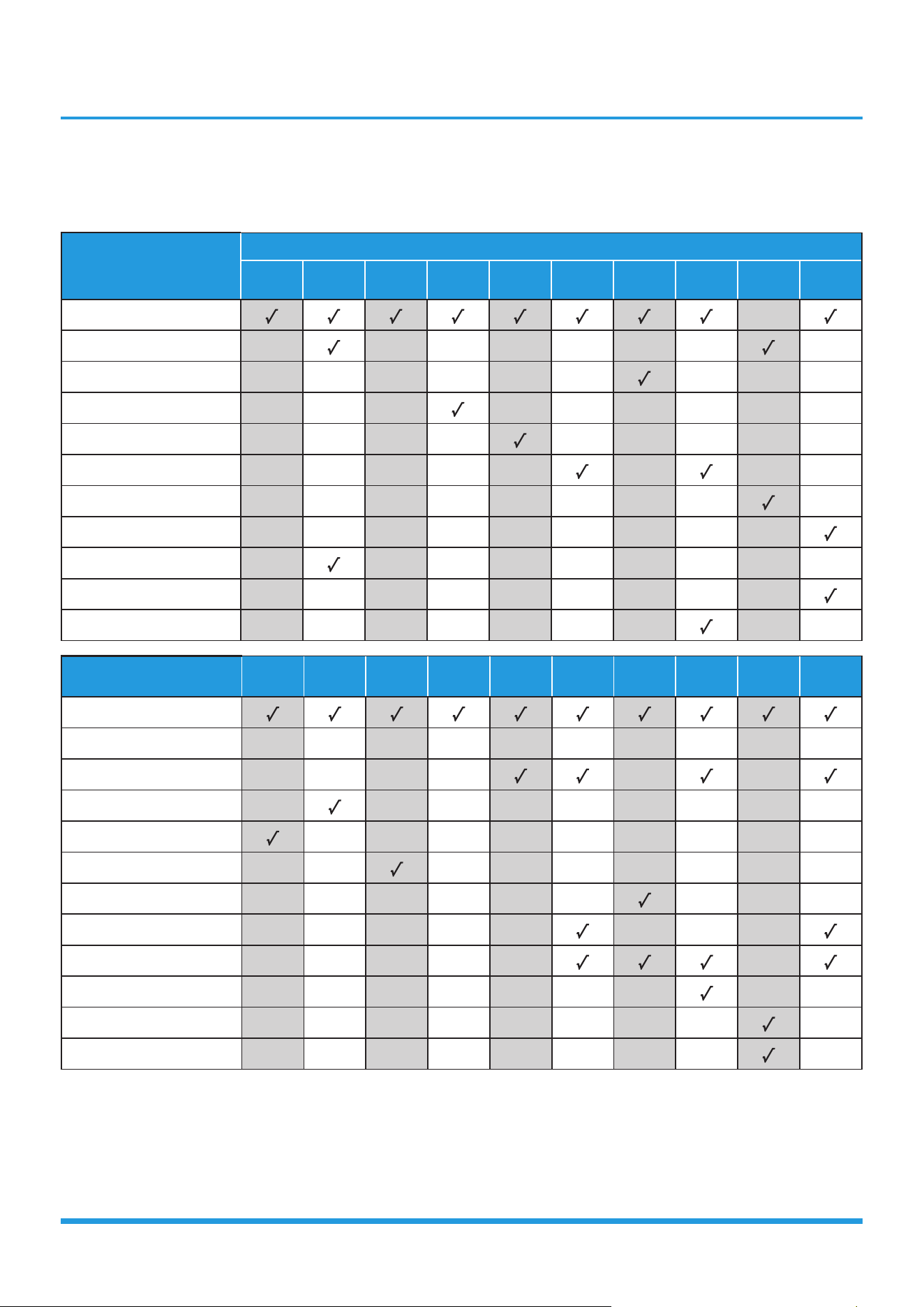
Troubleshooting 21
7. Quick Maintenance by Error Code
If you do not have the time to test which specific parts are faulty, you can directly change the required parts according
the error code. You can find the parts to replace by error code in the following table.
Part requiring
replacement
Error Code
EH 00/
EH 0A
EL 01 EH 02 EH 03 EH 60 EH 61 EH 0b EL 0C EC 56 FH CC
Indoor PCB
x
Outdoor PCB x x x x x x x x
Display board x x x x x x x x x
Indoor fan motor x x x x x x x x x
T1 sensor x x x x x x x x x
T2 Sensor x x x x x x x x
T2B Sensor x x x x x x x x x
Refrigerant sensor x x x x x x x x x
Reactor x x x x x x x x x
Compressor x x x x x x x x x
Additional refrigerant x x x x x x x x x
Part requiring
replacement
EC 53 EC 52 EC 54 EC 51 EC 07 PC 00 PC 01 PC 02 PC 03 PC 04
Outdoor PCB
Indoor fan motor x x x x x x x x x x
Outdoor fan motor x x x x x x
T3 Sensor x x x x x x x x x
T4 Sensor x x x x x x x x x
TP Sensor x x x x x x x x x
Reactor x x x x x x x x x
Compressor x x x x x x x x
IPM module board x x x x x x
High pressure protector x x x x x x x x x
Low pressure protector x x x x x x x x x
Additional refrigerant x x x x x x x x x
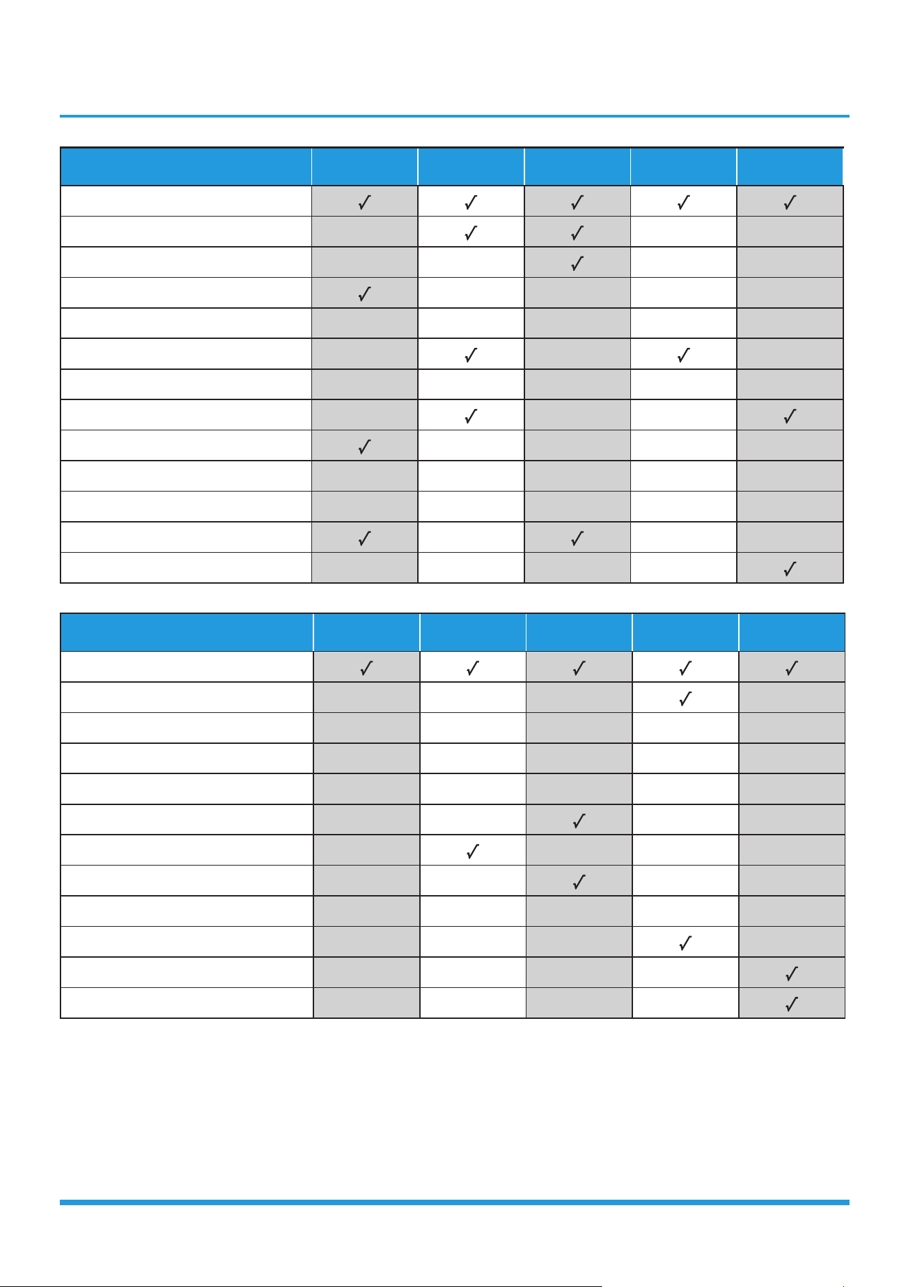
Troubleshooting 22
Part requiring replacement
pc 06 pc 08/44/ 49 pc 0a pc 0f PC 40
Outdoor PCB
Outdoor fan motor x x x
T3 Sensor x x x x
TP Sensor x x x x
Pressure sensor x x x x x
Reactor x x x
Compressor x x x x x
IPM module board x x x
High pressure valve assy x x x x
High pressure protector x x x x x
Low pressure protector x x x x x
Additional refrigerant x x x
Electric control box x x x x
Part requiring replacement
PC 41 PC 43 PC 10/11/12 PC 30 PC 31
Outdoor PCB
Outdoor fan motor x x x x
T3 Sensor x x x x x
TP Sensor x x x x x
Pressure sensor x x x x x
Reactor x x x x
Compressor x x x x
IPM module board x x x x
High pressure valve assy x x x x x
High pressure protector x x x x
Low pressure protector x x x x
Additional refrigerant x x x x
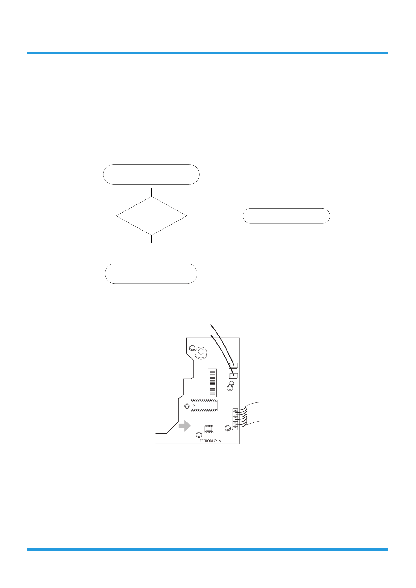
Troubleshooting
8. Troubleshooting by Error Code
TS01-IDU: IDU EEPROM malfunction or indoor EEPROM parameter error diagnosis and
solution
Description: Indoor PCB main chip does not receive feedback from EEPROM chip.
Recommended parts to prepare:
• Indoor PCB
Troubleshooting and repair:
Shut off the power supply and
turn it on 2 minutes later.
Is it still displaying
the error code?
YES
Replace the indoor main PCB.
The unit is operating normally. NO
Remarks:
EEPROM: A read-only memory whose contents can be erased and reprogrammed using a pulsed voltage.
The location of the EEPROM chip on the indoor PCB is shown in the following image:
Note: This pictures are only for reference, actual appearance may vary.
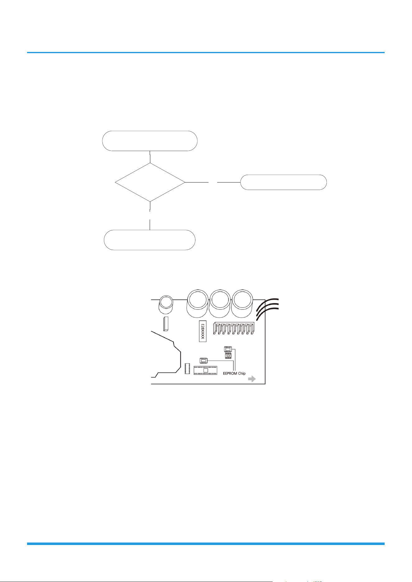
Troubleshooting
TS01-ODU: ODU EEPROM parameter error diagnosis and solution
Description: Outdoor PCB main chip does not receive feedback from EEPROM chip.
Recommended parts to prepare:
• Outdoor PCB
Troubleshooting and repair:
Shut off the power supply and
turn it on 2 minutes later.
Is it still displaying
the error code?
YES
Replace the outdoor main PCB.
The unit is operating normally
.
NO
Remarks:
EEPROM: A read-only memory whose contents can be erased and reprogrammed using a pulsed voltage.
The location of the EEPROM chip on the outdoor PCB is shown in the following image:
This pictures are only for reference, actual appearance may vary.
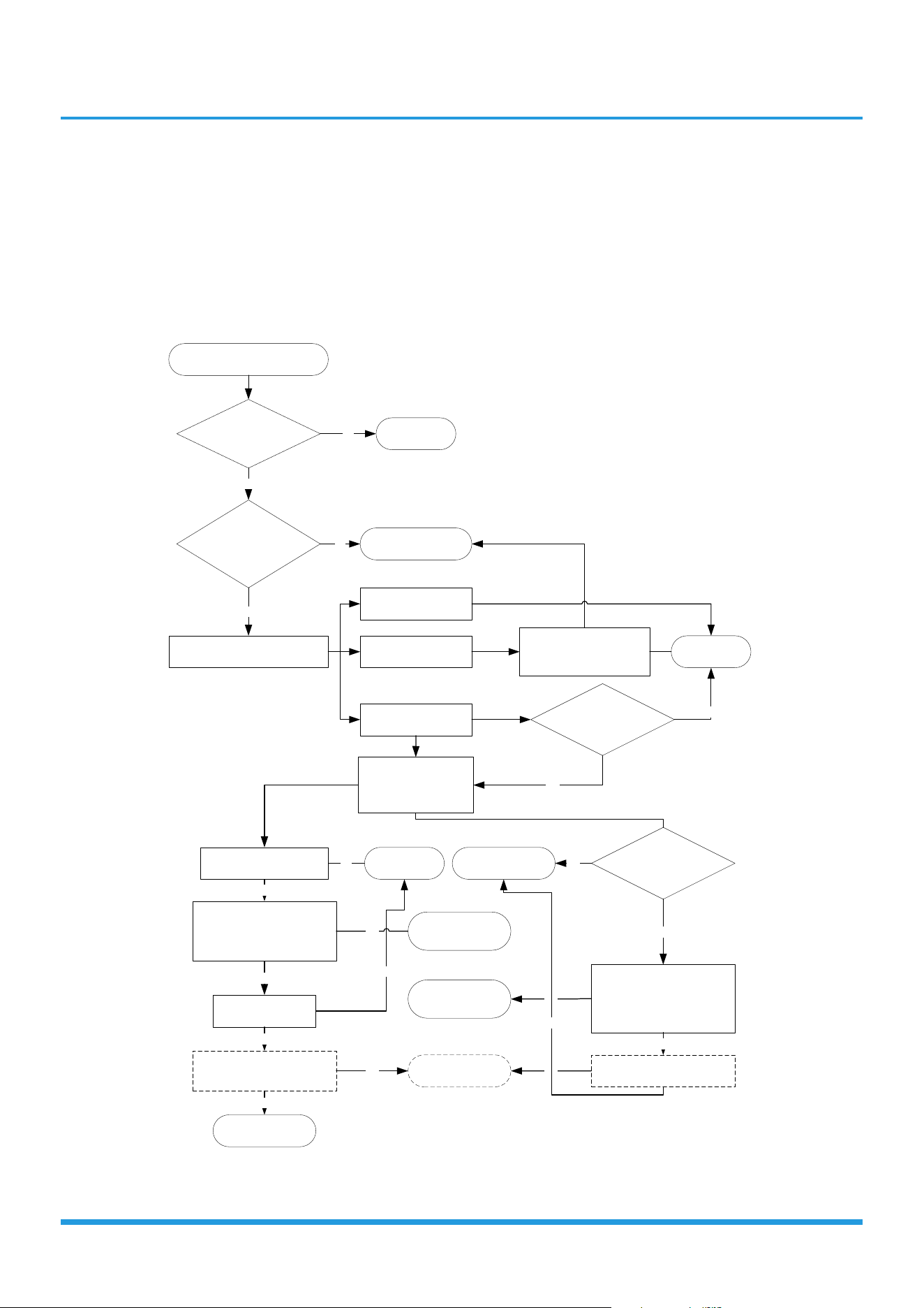
Troubleshooting
TS02-S-INV: IDU & ODU communication error diagnosis and solution
Description: Indoor unit can not communicate with outdoor unit
Recommended parts to prepare:
• Indoor PCB
• Outdoor PCB
• Short-circuited component
Troubleshooting and repair:
Does the error code
disappear?
Power off, then restart the unit after 2
minutes.
Measure the DC voltage between N/L2
and S (Black pin to S , Red pin to N/L2).
The value is fixed and close
to 0
The value is alternative
from neg ative to pos itive
The value is always positive
Check the wiring connection
between indoor and outdoor
unit, are they good?
Check the wiring connection
from outdoor terminal to
outdoor PCB and wiring
between PCBs if there is
more than 1 PCB
Check the wiring connection
from indoor terminal to indoor
PCB, are they good?
Turn on the unit, check if W
and 1(L) is connected?
Check if the power LED is
on?
Yes
Yes
Yes
Unplug all the high voltage
components connected to main
PCB such as 4 way valve, heater,
AC fan one by one to check their
resistance. Is there any component
short circuit?
Unplug electronic expansion valve.
Check if power LED is on?
No
No
Check the AC voltage of L, N
output to IPM board, is it same
as power input?
Check the DC 5V, 12V
from IPM board to main
PCB, are they normal?
Unplug all the high voltage
components connected to main
PCB such as 4 way valve, heater,
AC fan one by one to check their
resistance. Is there any component
short circuit?
Yes
No
Unplug electronic expansion valve.
Check if the DC 5V, 12V to main
PCB ar e OK
Replace short-circuited
component and main
PCB
Replace coil of electronic
expansion valve
Replace outdoor PCB
Replace short-circuited
component and outdoor
PCB
Yes
Yes
Yes
Yes
Replace main PCB
No
Yes
No
Replace IPM board
No
Repalce indoor PCB
No
Solved
Correct the connection or
change wires
No
No
Yes
For units with main PCB and IPM board
both
For units with only one
PCB
For units
with W wire
For units without W
wire
No
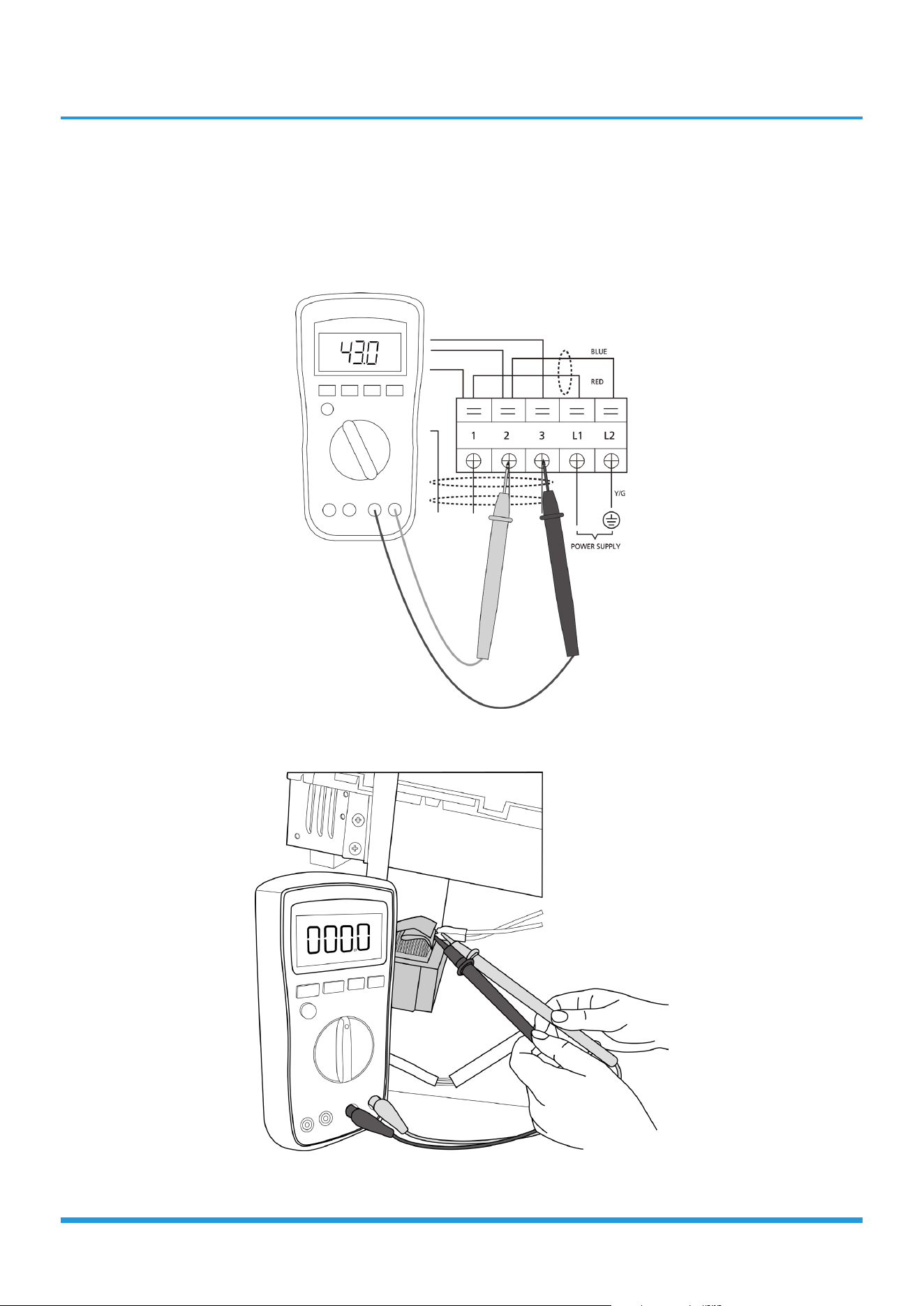
Troubleshooting
Remarks:
• Use a multimeter to test the DC voltage between 2 port(or S or L2 port) and 3 port(or N or S port) of outdoor unit.
The red pin of multimeter connects with 2 port(or S or L2 port) while the black pin is for 3 port(or N or S port) .
• When AC is normal running, the voltage will move alternately between -25V to 25V.
• If the outdoor unit has malfunction, the voltage will move alternately with positive value.
• While if the indoor unit has malfunction, the voltage will be a certain value.
• Use a multimeter to test the resistance of the reactor which does not connect with capacitor.
• The normal value should be around zero ohm. Otherwise, the reactor must have malfunction.
Note: The picture and the value are only for reference, actual condition and specific value may vary.
S and N
or
L2 and S
or
2 and 3
Troubleshooting
TS03: Zero crossing detection error diagnosis and solution
Description: When PCB does not receive zero crossing signal feedback for 4 minutes or the zero crossing signal time
interval is abnormal.
Recommended parts to prepare:
• Connection wires
• Indoor main PCB
Troubleshooting and repair:
Check the connections and
power supply.
Correct the connections. Turn on the
unit when the power supply is good.
NO
Indoor main PCB is defective. Replace
indoor main PCB.
YES
Is it normal?
Note: Zero crossing detection error is only valid for the unit with AC fan motor, for other models, this error is
invalid.
Troubleshooting
TS04-S-IDU: The Indoor fan speed is operating outside of normal range diagnosis and
solution)
Description: When indoor fan speed keeps too low or too high for a certain time, the LED displays the failure code and
the AC turns off.
Recommended parts to prepare:
• Connection wires
• Fan assembly
• Fan motor
• Indoor main PCB
Troubleshooting and repair:
YES
Power off, then restart the unit after 2 minutes.
Is it within normal parameters?
Replace the fan motor
Does a problem remain?
The unit is operating normallyNO
Shut off the power supply, Rotate
the fan by hand.
YES
Does it turn easily?
Find the cause
of the problem and resolve it
NO
Check the wiring of fan motor.
YES
Is it improperly wired?
Ensure proper connections
Measure the voltage for
the fan motor from the PCB.
YES
Replace the indoor main PCBNO
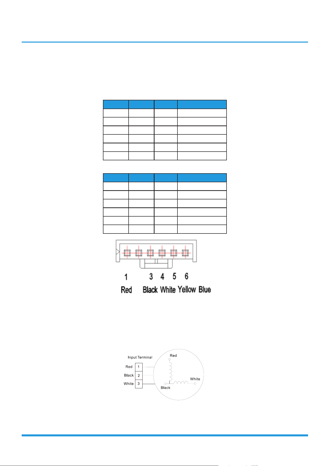
Troubleshooting
Index:
1. Indoor or Outdoor DC Fan Motor(control chip is in fan motor)
Power on and when the unit is in standby, measure the voltage of pin1-pin3, pin4-pin3 in fan motor connector. If the
value of the voltage is not in the range showing in below table, the PCB must has problems and need to be replaced.
• DC motor voltage input and output (voltage: 220-240V~):
No. Color Signal Voltage
1 Red Vs/Vm 192V~380V
2 --- --- ---
3 Black GND 0V
4 White Vcc 14-17.5V
5 Yellow Vsp 0~5.6V
6 Blue FG 14-17.5V
• DC motor voltage input and output (voltage: 115V~):
No. Color Signal Voltage
1 Red Vs/Vm 140V~190V
2 --- --- ---
3 Black GND 0V
4 White Vcc 14-17.5V
5 Yellow Vsp 0~5.6V
6 Blue FG 14-17.5V
2. Indoor AC Motor
1) Power on and set the unit running in fan mode at high fan speed. After running for 15 seconds, measure the voltage
of pin1 and pin2. If the value of the voltage is less than 100V(208~240V power supply) or 50V (115V power supply),
the PCB must has problems and need to be replaced.
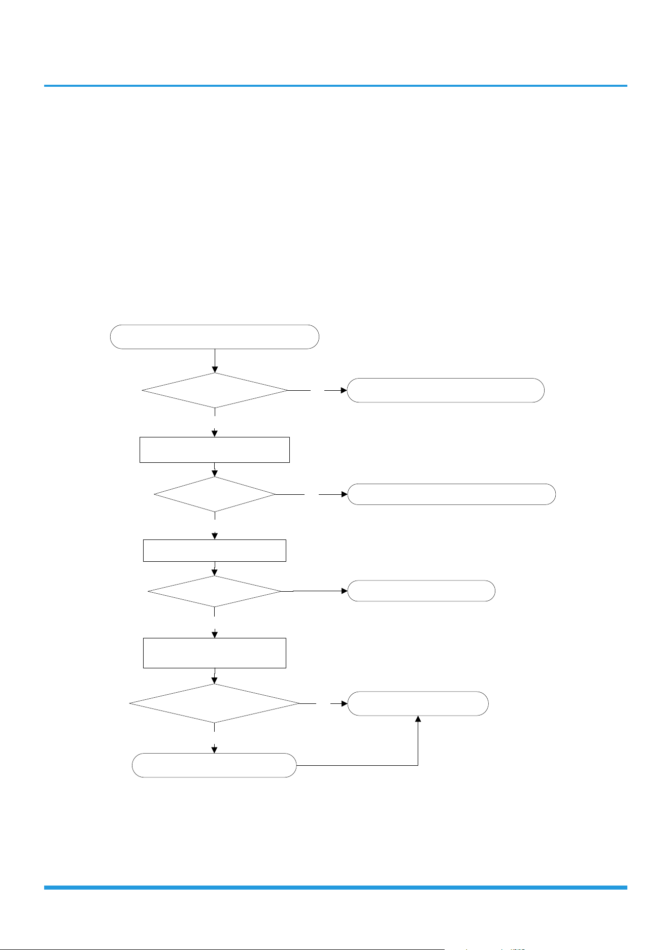
Troubleshooting
TS04-ODU: The outdoor fan speed is operating outside of normal range diagnosis and
solution)
Description: When outdoor fan speed keeps too low or too high for a certain time, the LED displays the failure code
and the AC turns off.
Recommended parts to prepare:
• Connection wires
• Fan assembly
• Fan motor
• Outdoor main PCB
Troubleshooting and repair:
YES
Power off, then restart the unit after 2 minutes.
Is it within normal parameters?
Replace the fan motor
Does a problem remain?
The unit is operating normallyNO
Shut off the power supply, Rotate
the fan by hand.
YES
Does it turn easily?
Find the cause
of the problem and resolve it
NO
Check the wiring of fan motor.
YES
Is it improperly wired?
Ensure proper connections
Measure the voltage for
the fan motor from the PCB.
YES
Replace the outdoor main PCBNO
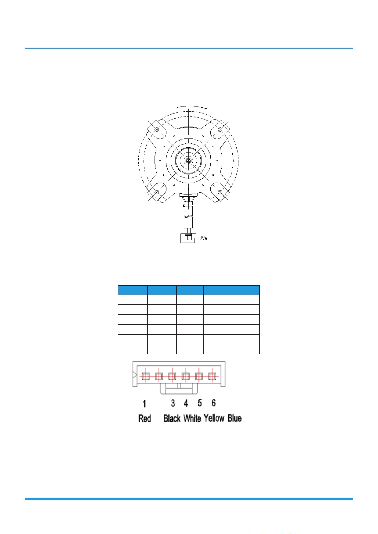
Troubleshooting
Index:
1. Outdoor DC Fan Motor (control chip is in outdoor PCB)
Release the UVW connector. Measure the resistance of U-V, U-W, V-W. If the resistance is not equal to each other, the
fan motor must has problems and need to be replaced. otherwise the PCB must has problems and need to be replaced.
2. DC Fan Motor(control chip is in fan motor, single fan)
Power on and when the unit is in standby, measure the voltage of pin1-pin3, pin4-pin3 in fan motor connector. If the
value of the voltage is not in the range showing in below table, the PCB must has problems and need to be replaced.
No. Color Signal Voltage
1 Red Vs/Vm 192V~380V
2 --- --- ---
3 Black GND 0V
4 White Vcc 13.5-16.5V
5 Yellow Vsp 0~6.5V
6 Blue FG 13.5-16.5V
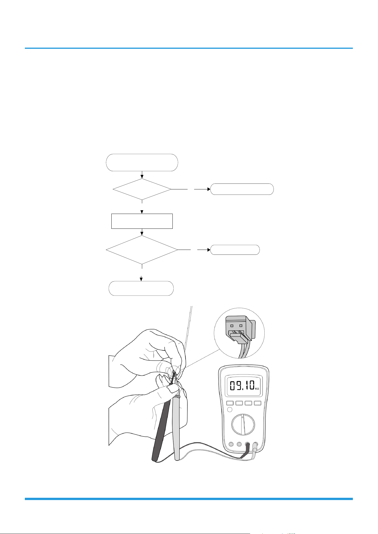
Troubleshooting
TS05-IDU: Open circuit or short circuit of indoor temperature sensor(T1, T2) diagnosis and
solution
Description: If the sampling voltage is lower than 0.06V or higher than 4.94V, the LED displays the failure code.
Recommended parts to prepare:
• Connection wires
• Sensors
• Indoor main PCB
Troubleshooting and repair:
Check the connection between
temperature sensor and PCB.
Replace the indoor main PCB
Is it within acceptable
parameters?
Is it properly wired? Ensure proper connections
.
NO
Measure the resistance value
of the sensor.
YES
Replace the sensor.
NO
YES
Note: This picture and the value are only for reference, actual appearance and value may vary.
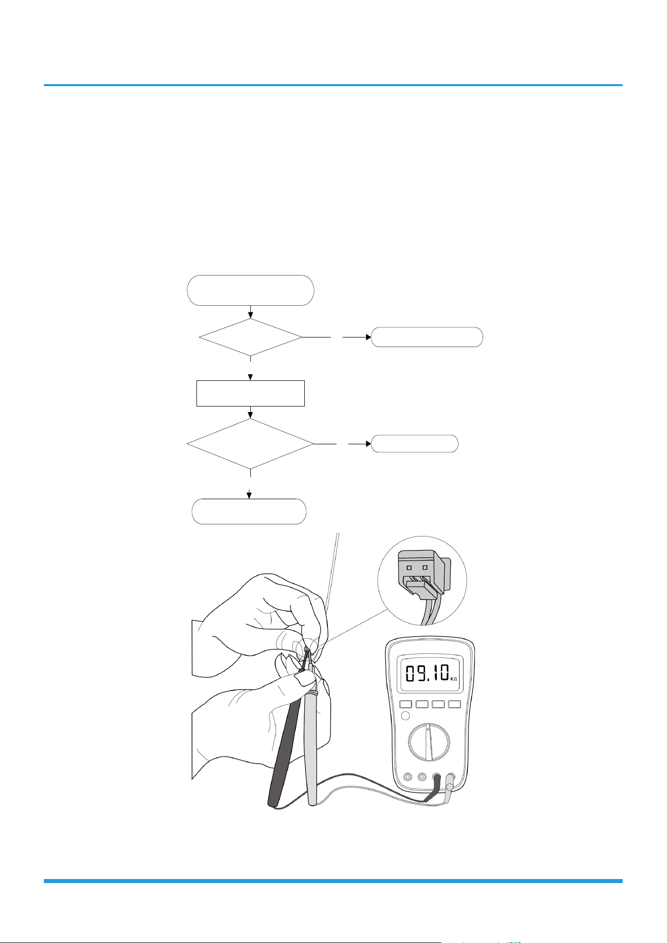
Troubleshooting
TS05-ODU: Open circuit or short circuit of outdoor temperature sensor(T3, T4, TP, T2B,TH)
diagnosis and solution
Description: If the sampling voltage is lower than 0.06V or higher than 4.94V, the LED displays the failure code.
Recommended parts to prepare:
• Connection wires
• Sensors
• Outdoor main PCB
Troubleshooting and repair:
Check the connection between
temperature sensor and PCB.
Replace the outdoor main PCB
Is it within acceptable
parameters?
Is it properly wired?
Ensure proper connections.
NO
Measure the resistance value
of the sensor.
YES
Replace the sensor.
NO
YES
For certain models, outdoor unit uses combination sensor, T3,T4 and TP are the same of sensor. This picture and
the value are only for reference, actual appearance and value may vary.
Troubleshooting
TS06-INV: System lacks refrigerant diagnosis and solution
Description:
Judging the abnormality of the refrigeration system according to the number of compressor stops and the changes in
operating parameters caused by excessive exhaust temperature.
Recommended parts to prepare:
• Indoor PCB
• Additional refrigerant
Troubleshooting and repair:
Power off, then restart the unit 15 minutes later.
Are any leakages present?
Put your hands in front of the
indoor air outlet.
Is there cool or heat
air blowing out from
indoor air outlet?
Ensure proper connections.
Check system for leakages.
NO
NO
Repair the leakage and
recharge the refrigerant.
YES
NO
Is T2 loose?
YES YES
Is T1 too close to
the evaporator
NO
Install correctly YES
Replace the indoor PCB
NO
Charge the refrigerant
appropriately(about 10% of
the nameplate charge)
Troubleshooting
TS07: Indoor PCB / Display board communication error diagnosis and solution
Description: Indoor PCB does not receive feedback from the display board.
Recommended parts to prepare:
• Communication wire
• Indoor PCB
• Display board
Troubleshooting and repair:
Is it still displaying the error code? The unit functions normally
Check the wirings and connections
Are all the connections
good?
Replace the indoor main PCB
Does the error still exist?
Replace the display board
Power off, then restart the unit 2 minutes
later
Ensure a proper connection
YES
NO
NO
YES
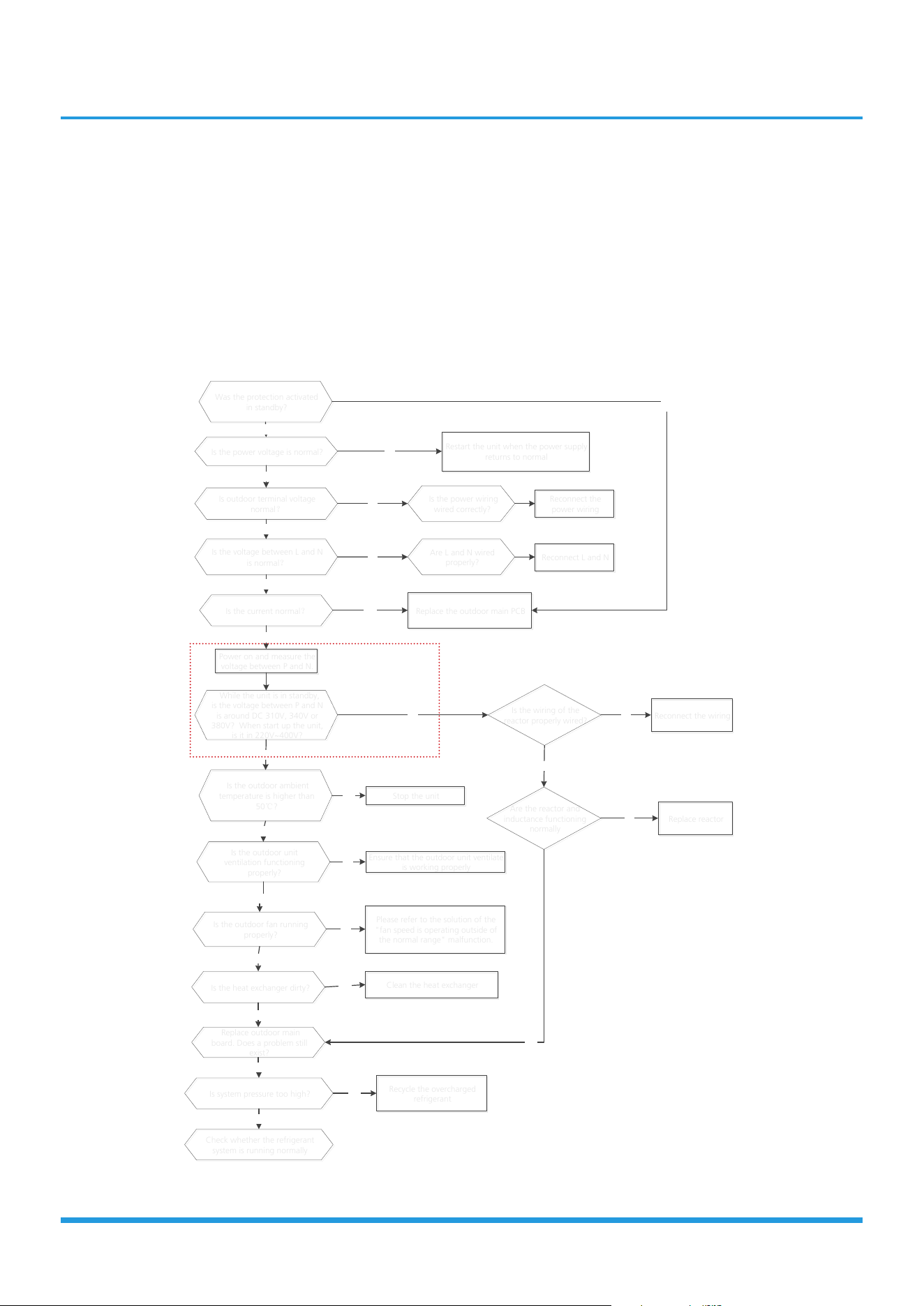
Troubleshooting
TS08-S: Current overload protection diagnosis and solution
Description: An abnormal current rise is detected by checking the specified current detection circuit.
Recommended parts to prepare:
• Connection wires
• Reactor
• Outdoor fan
• Outdoor PCB
Troubleshooting and repair:
Was the protection activated
in standby?
Was the protection activated
in standby?
Yes
Is the current normal?
Is
the current normal?
Yes
No
Replace the outdoor main PCB
R
eplace the outdoor main PCB
Is the power voltage is normal?
Is the power voltage is normal?
Is outdoor terminal voltage
normal?
Is outdoor terminal voltage
normal?
Restart the unit when the power supply
returns to normal
Restart the unit when the power supply
returns to normal
No
Yes
No
Reconnect the
power wiring
Reconnect the
power wiring
Yes
Is the voltage between L and N
is normal?
Is
the voltage between L and N
is normal?
Yes
No
Is the power wiring
wired correctly?
Is the power wiring
wired correctly?
Reconnect L and N
Rec
onnect L and N
Are L and N wired
properly?
Are L and N wired
properly?
No
No
While the unit is in standby,
is the voltage between P and N
is around DC 310V, 340V or
380V? When start up the unit,
is it in 220V~400V?
While the unit is in standby,
is the voltage between P and N
is around DC 310V, 340V or
380V
? When start up the unit,
is it in 220V~400V?
Is the wiring of the
reactor properly wired
?
Is the wiring of the
reactor properly wired?
Reconnect the wiring
Reconnect the wiring
No
Are the
reactor and
inductance functioning
normally
Are the reactor and
inductance functioning
normally
Yes
Replace reactor
Replace reactor
No
Is the outdoor ambient
temperature is higher than
50℃?
Is the outdoor ambient
temperature is higher than
50℃?
No
Stop the unit
Stop the unit
Yes
Is the outdoor unit
ventilation functioning
properly?
Is the outdoor unit
ventilation functioning
properly?
Yes
Ensure that the outdoor unit ventilate
is working properly
Ensure that the outdoor unit ventilate
is working properly
Is the heat exchanger dirty?
Is the heat exchanger dirty?
No
Clean the heat exchanger
Clean the heat exchanger
Yes
Check whether the refrigerant
system is running normally
Check whether the refrigerant
system is running normally
Replace outdoor main
board. Does a problem still
exist?
Replace outdoor main
board. Does a problem still
exist?
Yes
No
Is the outdoor fan running
properly?
Is the outdoor fan running
properly?
Please refer to the solution of the
"fan speed is operating outside of
the normal range" malfunction.
Please refer to the solution of the
"fan speed is operating outside of
the normal range" malfunction.
No
Yes
No
Yes
Yes
Is system pressure too high?
Is system pressure too high?
Recycle the overcharged
refrigerant
Recycle the overcharged
refrigerant
Yes
Power on and measure the
voltage between P and N.
Power on and measure the
voltage between P and N.
Skip this step for
models which
electric control
box cover cannot
be removed.See
the disassembly
guide for details.
Troubleshooting
TS05-N10: Refrigerant sensor error or Refrigerant sensor is out of range diagnosis and
solution
Description: Indoor unit receives fault signal for 10s or indoor unit does not receive feedback from refrigerant sensor for
150s.
Recommended parts to prepare:
• Connection wires
• Sensors
• Indoor main PCB
Troubleshooting and repair:
Check the connection between
refrigerant sensor and PCB.
If the fault still exists, replace
the indoor main PCB
Is it properly wired?
Ensure proper connections.
NO
YES
Replace the sensor.
Troubleshooting
TS06-N10: Refrigerant sensor detects leakage or Refrigerant sensor is out of range and
leakage is detected diagnosis and solution
Description:
The refrigerant sensor detects a concentration higher than or equal to 10%*LFL for 10 seconds or the refrigerant sensor
detects a concentration higher than or equal to 20%*LFL or the multi model receives the refrigerant leakage protection
fault sent by the outdoor unit.
Multi-zone: Only the buzzer of the indoor unit that detects refrigerant leakage continues to sound the alarm, the
shortest sound is 10 seconds, and the longest sound is 5 minutes (you can press any key such as remote control or wire
control, APP and so on to eliminate the alarm), and the other non-refrigerant leakage fault indoor unit only displays
ECC1, but the buzzer does not sound.
Recommended parts to prepare:
• Additional refrigerant
Troubleshooting and repair:
Power off, then restart the unit 2 minutes later.
Are any leakages
present?
Check System for blockages and
clear blockages if present.
Does a problem remain?
YES
Check system for leakages.
NO
Repair the leakage and recharge
the refrigerant.
YES
NO
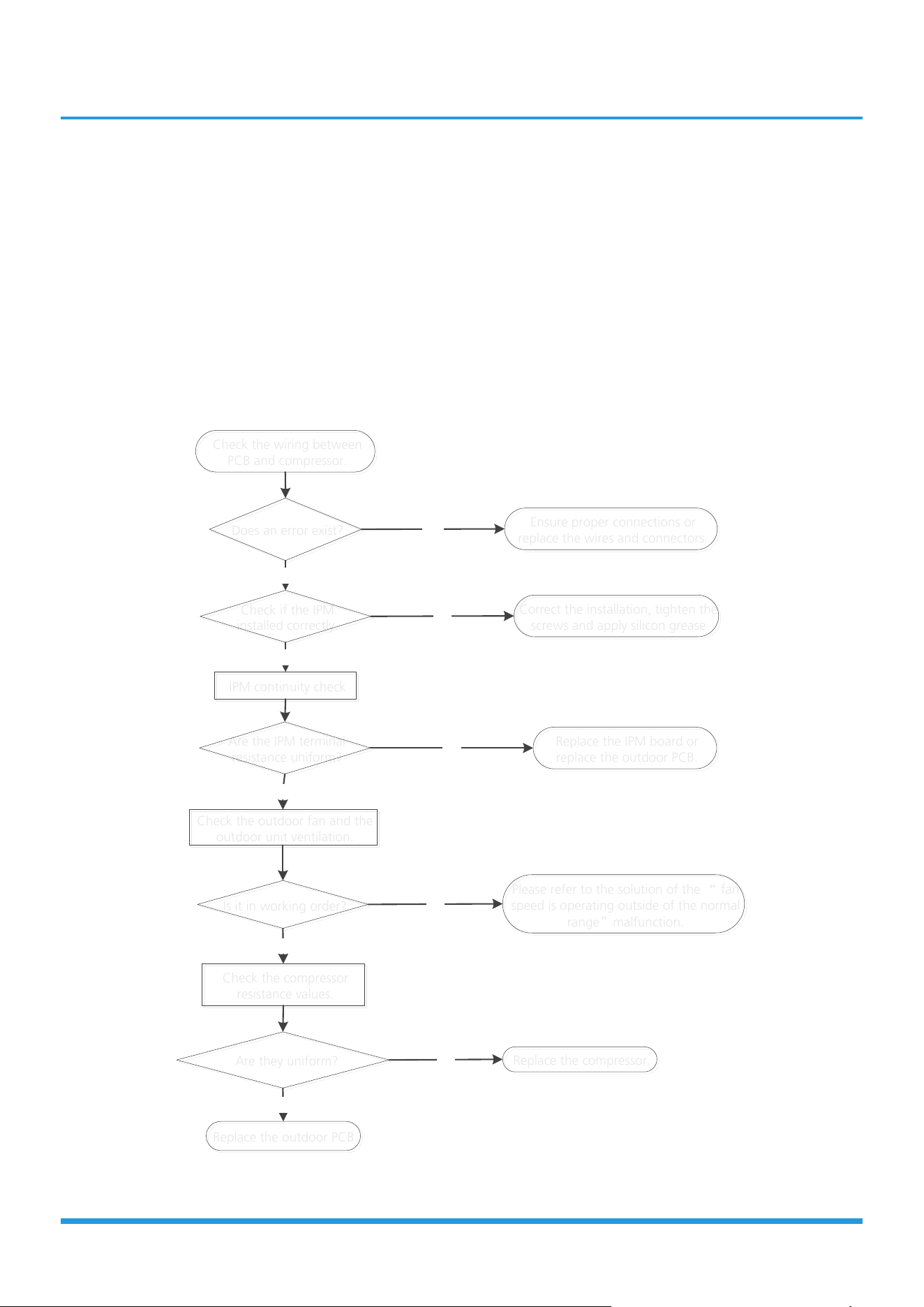
Troubleshooting
TS09-S: ODU IPM module protection diagnosis and solution
Description: When the voltage signal the IPM sends to the compressor drive chip is abnormal, the LED displays the
failure code and the AC turns off.
Recommended parts to prepare:
• Connection wires
• IPM module board
• Outdoor fan assembly
• Compressor
• Outdoor PCB
Troubleshooting and repair:
Check the wiring between
PCB and compressor.
Check the wiring between
PCB and compressor.
Does an error exist?
Does an error exist?
Ensure proper connections or
replace the wires and connectors.
Ensure proper connections or
replace the wires and connectors.
YES
NO
Are the IPM terminal
resistance uniform?
Are the IPM terminal
resistance uniform?
Replace the IPM board or
replace the outdoor PCB.
Replace the IPM board or
replace the outdoor PCB.
NO
Check the outdoor fan and the
outdoor unit ventilation.
Check the outdoor fan and the
outdoor unit ventilation.
YES
Is it in working order?
Is it in working order?
Please refer to the solution of the “ fan
speed is operating outside of the normal
range”malfunction.
Please refer to the solution of the “ fan
speed is operating outside of the normal
range”malfunction.
NO
Check the compressor
resistance values.
Check the compressor
resistance values.
YES
Are they uniform?
Are they uniform?
Replace the compressor.
Replace the compressor.
Replace the outdoor PCB.
Replace the outdoor PCB.
YES
NO
Check if the IPM
installed correctly.
Check if the IPM
installed correctly.
YES
NO
Correct the installation, tighten the
screws and apply silicon grease
Correct the installation, tighten the
screws and apply silicon grease
IPM continuity check
IPM continuity check
Troubleshooting
TS10-S: ODU voltage protection diagnosis and solution
Description: Abnormal increases or decreases in voltage are detected by checking the specified voltage detection circuit.
Recommended parts to prepare:
• Power supply wires
• IPM module board
• PCB
• Reactor
Troubleshooting and repair:
Check the power supply.
Is it in working order? Turn off the unit.
NO
Check the connections and wires.
YES
Are they in working order?
Ensure proper connections or
replace the wires.
NO
Power on and measure the
voltage between P and N.
YES
While the unit is in standby,
is the voltage between P and N is around
DC 310V, 340V or 380V? When start up
the unit, is it in 220V~400V?
Replace the IPM board.
NO
Check the reactor.
YES
Is it in working order?
Replace outdoor PCB.YES
Replace the reactor.
NO
Skip this step for models which
electric control box cover cannot
be removed.See the disassembly
guide for details.
Troubleshooting
TS11-S-INV: Compressor top (or IPM) temp. protection diagnosis and solution
Description: If the temperature of IPM module is higher than a certain value, the LED displays the failure code.
Recommended parts to prepare:
• Connection wires
• Outdoor PCB
• IPM module board
• High pressure protector
• System blockages
Troubleshooting and repair:
Check the fastening screws on the
PCB and IPM radiator.
Are they
fixed tightly?
Replace the outdoor
control PCB.
Tighten the screws and apply
silicon grease.
NO
YES
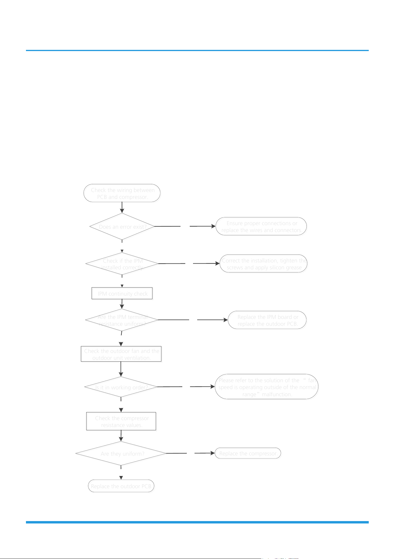
Troubleshooting
TS12-S: Inverter compressor drive error diagnosis and solution
Description: An abnormal inverter compressor drive is detected by a special detection circuit, including communication
signal detection, voltage detection, compressor rotation speed signal detection and so on.
Recommended parts to prepare:
• Connection wires
• IPM module board
• Outdoor fan assembly
• Compressor
• Outdoor PCB
Troubleshooting and repair:
Check the wiring between
PCB and compressor.
Check the wiring between
PCB and compressor.
Does an error exist?
Does an error exist?
Ensure proper connections or
replace the wires and connectors.
Ensure proper connections or
replace the wires and connectors.
YES
NO
Are the IPM terminal
resistance uniform?
Are the IPM terminal
resistance uniform?
Replace the IPM board or
replace the outdoor PCB.
Replace the IPM board or
replace the outdoor PCB.
NO
Check the outdoor fan and the
outdoor unit ventilation.
Check the outdoor fan and the
outdoor unit ventilation.
YES
Is it in working order?
Is it in working order?
Please refer to the solution of the “ fan
speed is operating outside of the normal
range”malfunction.
Please refer to the solution of the “ fan
speed is operating outside of the normal
range”malfunction.
NO
Check the compressor
resistance values.
Check the compressor
resistance values.
YES
Are they uniform?
Are they uniform?
Replace the compressor.
Replace the compressor.
Replace the outdoor PCB.
Replace the outdoor PCB.
YES
NO
Check if the IPM
installed correctly.
Check if the IPM
installed correctly.
YES
NO
Correct the installation, tighten the
screws and apply silicon grease
Correct the installation, tighten the
screws and apply silicon grease
IPM continuity check
IPM continuity check

Troubleshooting
TS26-INV: System Pressure protection(low or high pressure) diagnosis and solution
Description: Outdoor pressure switch cut off the system because high pressure is higher than 4.4 MPa or outdoor
pressure switch cut off the system because low pressure is lower than 0.13 MPa, the LED displays the failure code.
Recommended parts to prepare:
• Connection wires
• Outdoor PCB
• Refrigerant
• Pressure switch
• Outdoor fan
Troubleshooting and repair:
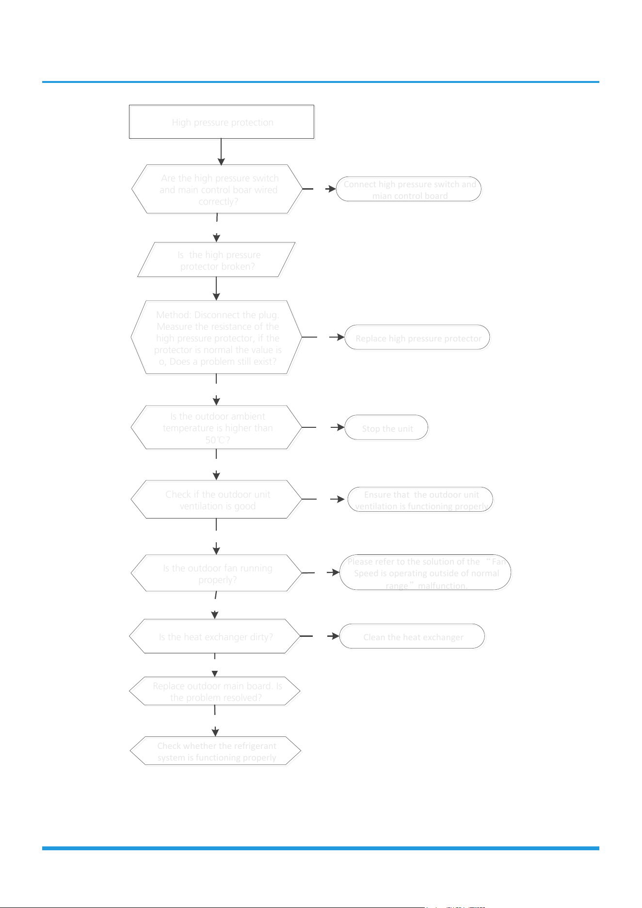
Troubleshooting
Are the high pressure switch
and main control boar wired
correctly?
Are the high pressure switch
and main control boar wired
correctly?
Method: Disconnect the plug.
Measure the resistance of the
high pressure protector, if the
protector is normal the value is
o, Does a problem still exist?
Method: Disconnect the plug.
Measure the resistance of the
high pressure protector, if the
protector is normal the value is
o, Does a problem still exist?
Yes
Yes
No
No
Is the high pressure
protector broken?
Is the high pressure
protector broken?
Is the outdoor ambient
temperature is higher than
50℃?
Is the outdoor ambient
temperature is higher than
50℃?
No
Yes
Check if the outdoor unit
ventilation is good
Check if the outdoor unit
ventilation is good
Yes
Is the heat exchanger dirty?
Is the heat exchanger dirty?
No
Yes
Replace outdoor main board. Is
the problem resolved?
Replace outdoor main board. Is
the problem resolved?
No
High pressure protection
High pressure protection
Is the outdoor fan running
properly?
Is the outdoor fan running
properly?
No
Yes
NO
Connect high pressure switch and
mian control board
Connect high pressure switch and
mian control board
Replace high pressure protector
Replace high pressure protector
Stop the unit
Stop the unit
Ensure that the outdoor unit
ventilation is functioning properly
Ensure that the outdoor unit
ventilation is functioning properly
Please refer to the solution of the “Fan
Speed is operating outside of normal
range”malfunction.
Please refer to the solution of the “Fan
Speed is operating outside of normal
range”malfunction.
Clean the heat exchanger
Clean the heat exchanger
Check whether the refrigerant
system is functioning properly
Check whether the refrigerant
system is functioning properly
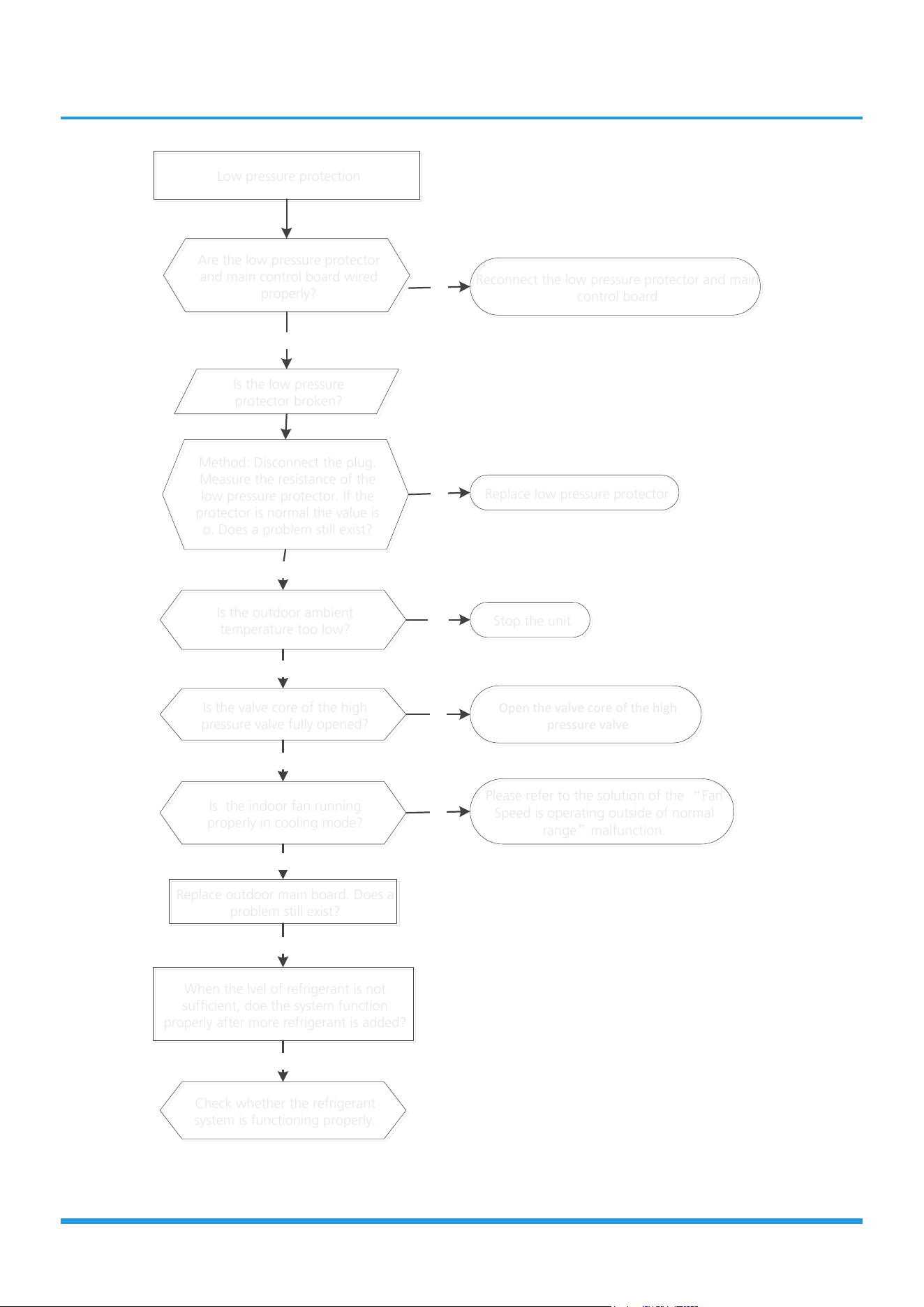
Troubleshooting
Low pressure protection
Low pressure protection
Are the low pressure protector
and main control board wired
properly?
Are the low pressure protector
and main control board wired
properly?
Method: Disconnect the plug.
Measure the resistance of the
low pressure protector. If the
protector is normal the value is
o. Does a problem still exist?
Method: Disconnect the plug.
Measure the resistance of the
low pressure protector. If the
protector is normal the value is
o. Does a problem still exist?
Yes
Yes
Replace outdoor main board. Does a
problem still exist?
Replace outdoor main board. Does a
problem still exist?
No
No
Is the low pressure
protector broken?
Is the low pressure
protector broken?
Is the outdoor ambient
temperature too low?
Is the outdoor ambient
temperature too low?
No
Yes
No
Is the valve core of the high
pressure valve fully opened?
Is the valve core of the high
pressure valve fully opened?
Is the indoor fan running
properly in cooling mode?
Is the indoor fan running
properly in cooling mode?
No
Yes
Yes
No
Check whether the refrigerant
system is functioning properly.
Check whether the refrigerant
system is functioning properly.
When the lvel of refrigerant is not
sufficient, doe the system function
properly after more refrigerant is added?
When the lvel of refrigerant is not
sufficient, doe the system function
properly after more refrigerant is added?
No
Reconnect the low pressure protector and main
control board
Reconnect the low pressure protector and main
control board
Replace low pressure protector
Replace low pressure protector
Open the valve core of the high
pressure valve
Open the valve core of the high
pressure valve
Stop the unit
Stop the unit
Please refer to the solution of the “Fan
Speed is operating outside of normal
range”malfunction.
Please refer to the solution of the “Fan
Speed is operating outside of normal
range”malfunction.
Troubleshooting
TS14: IDUs mode conflict (match with multi outdoor unit)
Description: The indoor units cannot work cooling mode and heating at same time. Heating mode has a priority.
• Suppose Indoor unit A working in cooling mode or fan mode, and indoor unit B is set to heating mode, then A will
change to off and B will work in heating mode.
• Suppose Indoor unit A working in heating mode, and indoor unit B is set to cooling mode or fan mode, then B will
change to stand by and A will be no change.
Cooling mode Heating Mode Fan Off
Cooling mode No Yes No No
Heating Mode Yes No Yes No
Fan No Yes No No
Off No No No No
Note:
No: No mode conflict
Yes: Mode conflict
LP (Low temperature protection of outdoor uni)
Description: It is a protection function. When compressor is off, outdoor ambient temperature(T4) is lower than -35
o
C.
for 10s, the AC will stop and display the failure code.
When compressor is on, outdoor ambient temperature(T4) is lower than -40
o
C.for 10s, the AC will stop and display the
failure code.
When outdoor ambient temperature(T4) is no lower than -32
o
C.for 10s, the unit will exit protection.
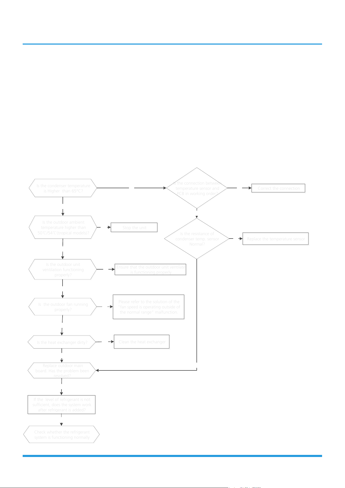
Troubleshooting
TS27-INV: High temperature protection of condenser diagnosis and solution
Description: When the outdoor pipe temperature is more than 65°C, the unit stops. It starts again only when the
outdoor pipe temperature is less than 52°C.
Recommended parts to prepare:
• Connection wires
• Condenser temperature sensor
• Outdoor fan
• Outdoor main PCB
• Refrigerant
Troubleshooting and repair:
Is the condenser temperature
is Higher than 65°C?
Is the condenser temperature
is Higher than 65°C?
Yes
Is the resistance of
condenser temp. sensor
Normal?
Is the resistance of
condenser temp. sensor
Normal?
Replace the temperature sensor
Replace the temperature sensor
No
No
Is the outdoor ambient
temperature higher than
50℃/54℃(tropical models)?
Is the outdoor ambient
temperature higher than
50℃/54℃(tropical models)?
No
Stop the unit
Stop the unit
Yes
Is the outdoor unit
ventilation functioning
properly?
Is the outdoor unit
ventilation functioning
properly?
Yes
Ensure that the outdoor unit ventilate
is functioning properly
Ensure that the outdoor unit ventilate
is functioning properly
Is the heat exchanger dirty?
Is the heat exchanger dirty?
No
Clean the heat exchanger
Clean the heat exchanger
Yes
Check whether the refrigerant
system is functioning normally
Check whether the refrigerant
system is functioning normally
Replace outdoor main
board. Has the problem been
resolved?
Replace outdoor main
board. Has the problem been
resolved?
No
If the level of refrigerant is not
sufficient, does the system work
after refrigerant is added?
If the level of refrigerant is not
sufficient, does the system work
after refrigerant is added?
No
Is the outdoor fan running
properly?
Is the outdoor fan running
properly?
Please refer to the solution of the
"fan speed is operating outside of
the normal range" malfunction.
Please refer to the solution of the
"fan speed is operating outside of
the normal range" malfunction.
No
Yes
No
Correct the connection
Correct the connection
No
Yes
Is the connection between
temperature sensor and
PCB in working order?
Is the connection between
temperature sensor and
PCB in working order?
Yes
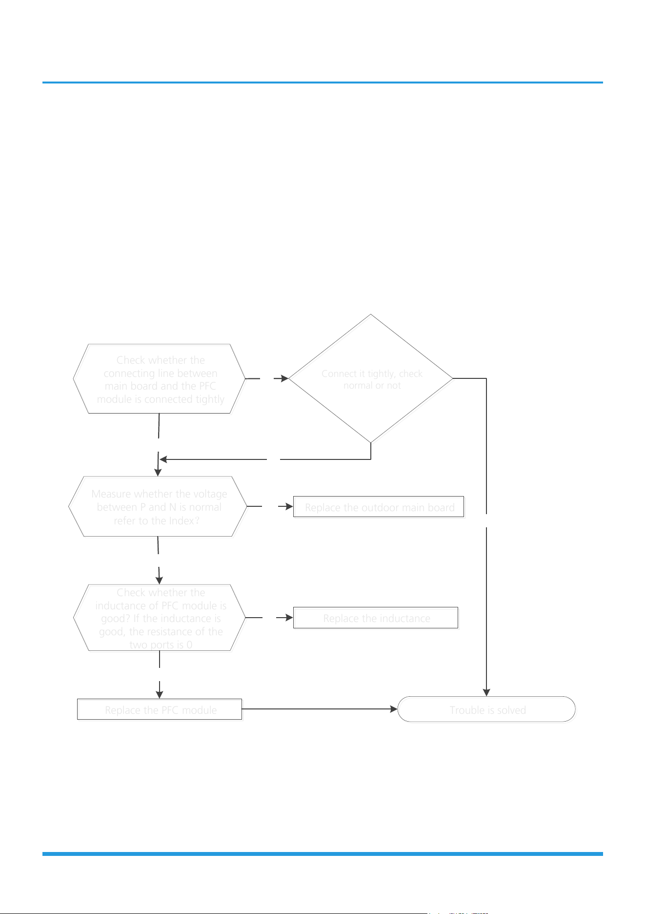
Troubleshooting
TS30: PFC module protection diagnosis and solution
Description: When the voltage signal that IPM send to compressor drive chip is abnormal, the LED displays the failure
code and the AC turns off.
Recommended parts to prepare:
• Connection wires
• Inductance
• Outdoor main PCB
• PFC module
Troubleshooting and repair:
At first test the resistance between every two ports of U, V, W of IPM and P, N. If any result of them is 0 or close to 0, the
IPM is defective. Otherwise, please follow the procedure below:
Check whether the
connecting line between
main board and the PFC
module is connected tightly
Check whether the
connecting line between
main board and the PFC
module is connected tightly
Yes
Measure whether the voltage
between P and N is normal
refer to the Index?
Measure whether the voltage
between P and N is normal
refer to the Index?
No
Check whether the
inductance of PFC module is
good? If the inductance is
good, the resistance of the
two ports is 0
Check whether the
inductance of PFC module is
good? If the inductance is
good, the resistance of the
two ports is 0
Yes
Replace the inductance
Replace the inductanceNo
Connect it tightly, check
normal or not
Connect it tightly
, check
normal or not
Replace the outdoor main board
Replace the outdoor main boardYes
Yes
No
No
Replace the PFC module
Replace the PFC module
Trouble is solved
Trouble is solved
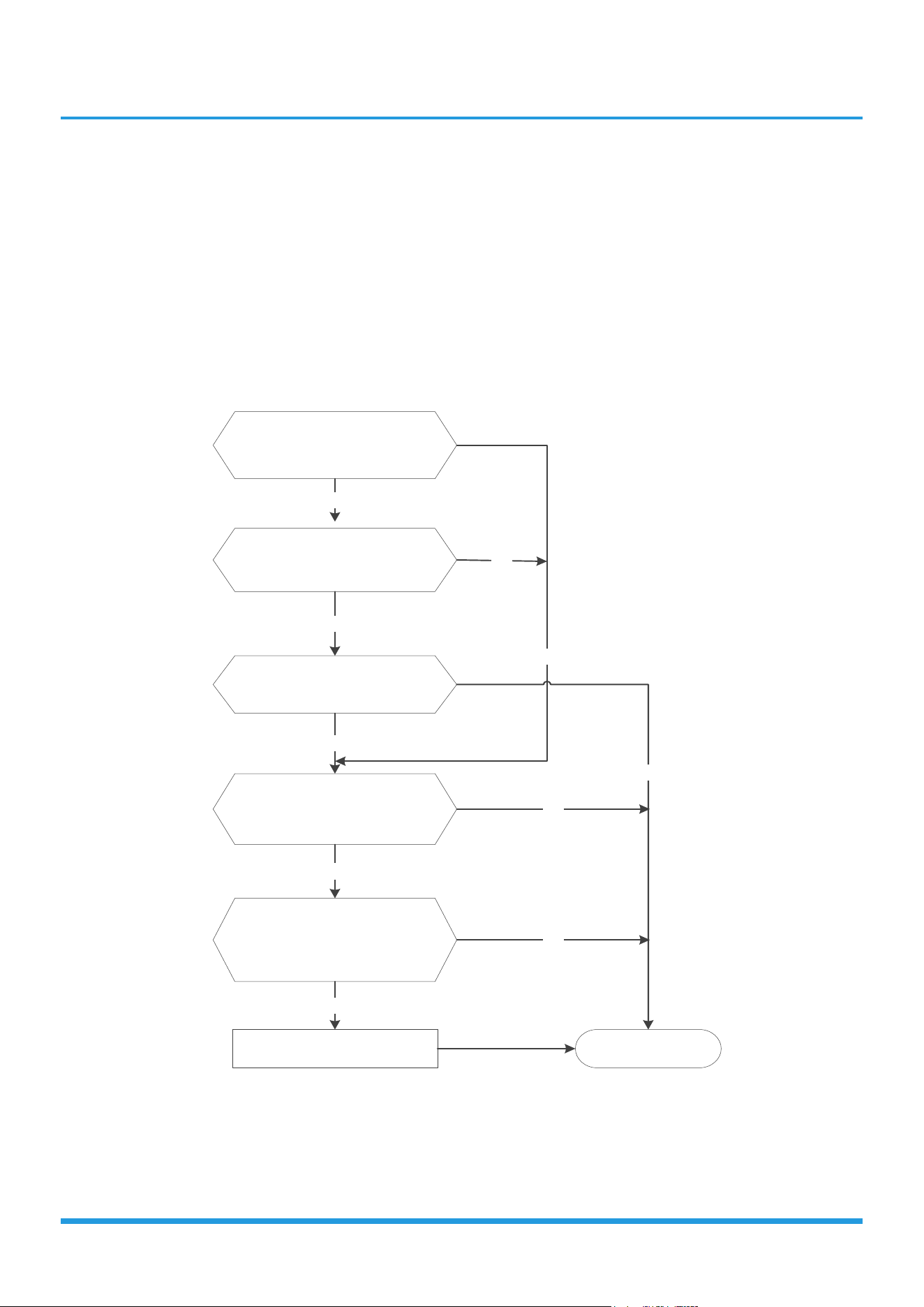
Troubleshooting
TS31: Communication error between outdoor main chip and compressor driven chip
diagnosis and solution
Description: The main PCB cannot detect the IPM board.
Recommended parts to prepare:
• Connection wires
• IPM board
• Outdoor main PCB
• Electric control box
Troubleshooting and repair:
Is there at least one LED in the
compressor driven chip light?
Check the signal wire between the
Compressor driven chip and the
main board, is it connected
properly?
Reconnect and retry. Is the
error still displayed?
Replace Compressor driven
Chip. Is the system running
normally?
Replace the electric control box
No
No
No
No
Yes
Problem is resolved
No
Yes
Replace outdoor main board.
Is the system running
normally?
No
Yes
Yes
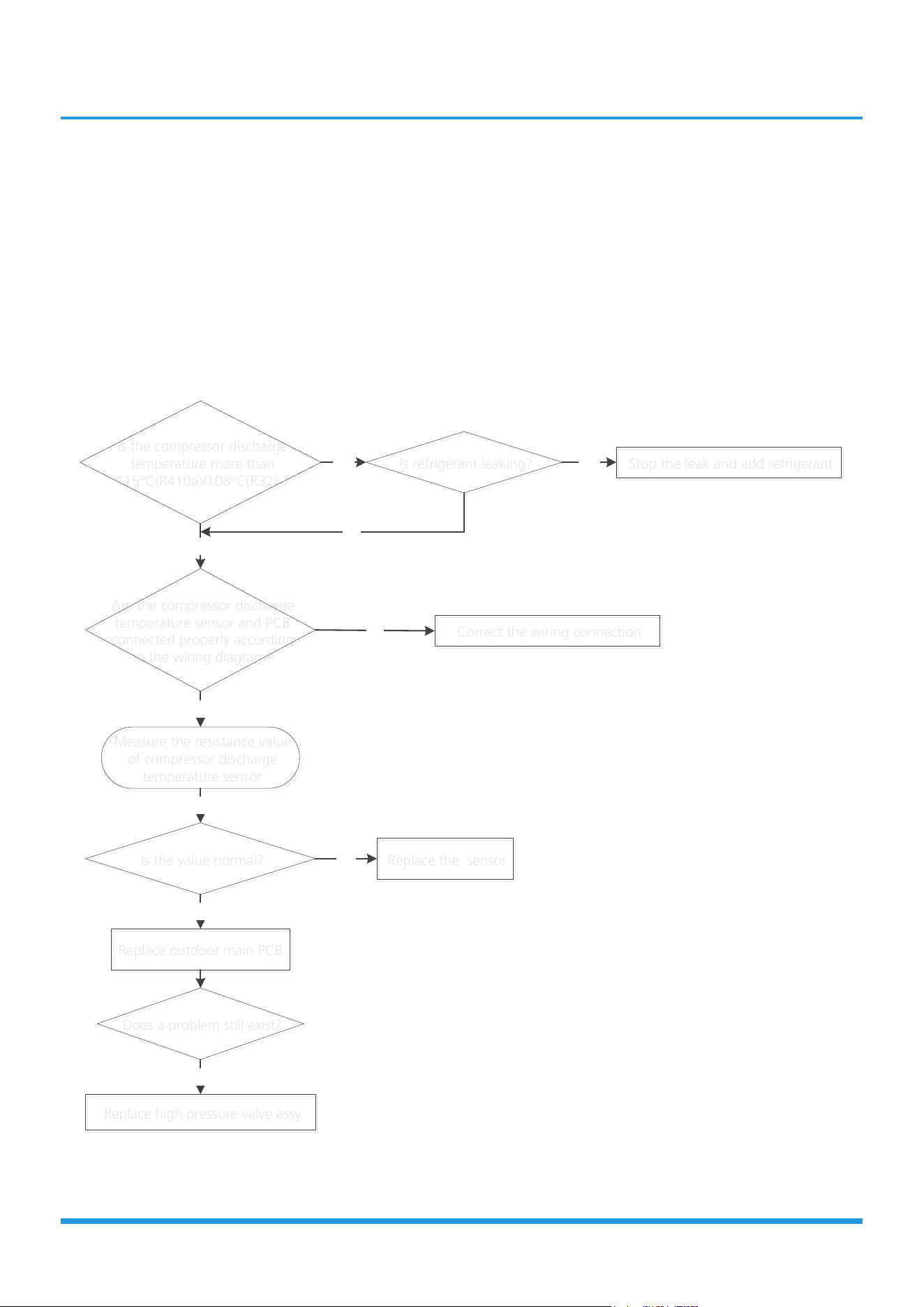
Troubleshooting
TS32: Discharge temperature protection of compressor diagnosis and solution
Description: If the compressor discharge temperature exceeds a certain level for nine seconds, the compressor ceases
operation, the LED displays the failure code
Recommended parts to prepare:
• Connection wires
• Discharge temperature sensor
• Additional refrigerant
• Outdoor main PCB
Troubleshooting and repair:
No
Yes
Yes
No
Correct the wiring connection
Correct the wiring connection
Stop the leak and add refrigerant
Stop the leak and add refrigerant
Yes
Replace high pressure valve assy
Replace high pressure valve assy
Yes
No
YES
Is refrigerant leaking?
Is refrigerant leaking?
Are the compressor discharge
temperature sensor and PCB
connected properly according
to the wiring diagram?
Are the compressor discharge
temperature sensor and PCB
connected properly according
to the wiring diagram?
Is the compressor discharge
temperature more than
115°C(R410a)/108°C(R32) ?
Is the compressor discharge
temperature more than
115°C(R410a)/108°C(R32) ?
Is the value normal?
Is the value normal?
Measure the resistance value
of compressor discharge
temperature sensor
Measure the resistance value
of compressor discharge
temperature sensor
YES
Replace the sensor
Replace the sensor
NO
Replace outdoor main PCB.
Replace outdoor main PCB.
Does a problem still exist?
Does a problem still exist?
Note: For certain models, outdoor unit uses combination sensor, T3,T4 and TP are the same of sensor. This
picture and the value are only for reference, actual appearance and value may vary.
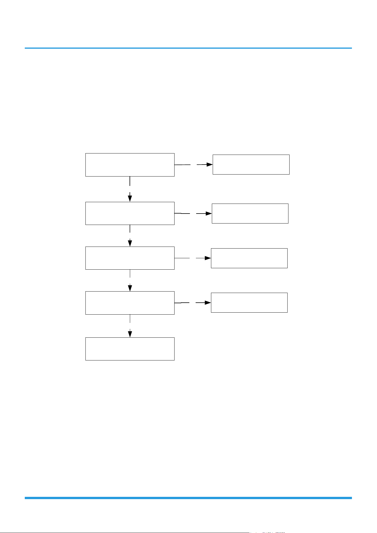
Troubleshooting
TS38: Lack phase failure of ODU DC fan motor diagnosis and solution
Description: When the three-phase sampling current of the DC motor is abnormal, especially when the current of one
or more phases is always small and almost 0, the LED displays the failure code.
Recommended parts to prepare:
• Connection wire
• Fan motor
• Outdoor PCB
Troubleshooting and repair:
Check the fan three-phase
output for obvious open circuit
Power off,then restart the unit
2 minutes later.Is it still
displaying the error code
The unit operates
normally
Check the wiring of fan
motor.Are all the connections
good?
Correct the connections
Check whether the three-
phase resistance of the fan is
symmetrical
Replace the fan motor
Yes
Yes
Yes
No
No
No
Replace the main PCB
No
Trouble is solved
Yes
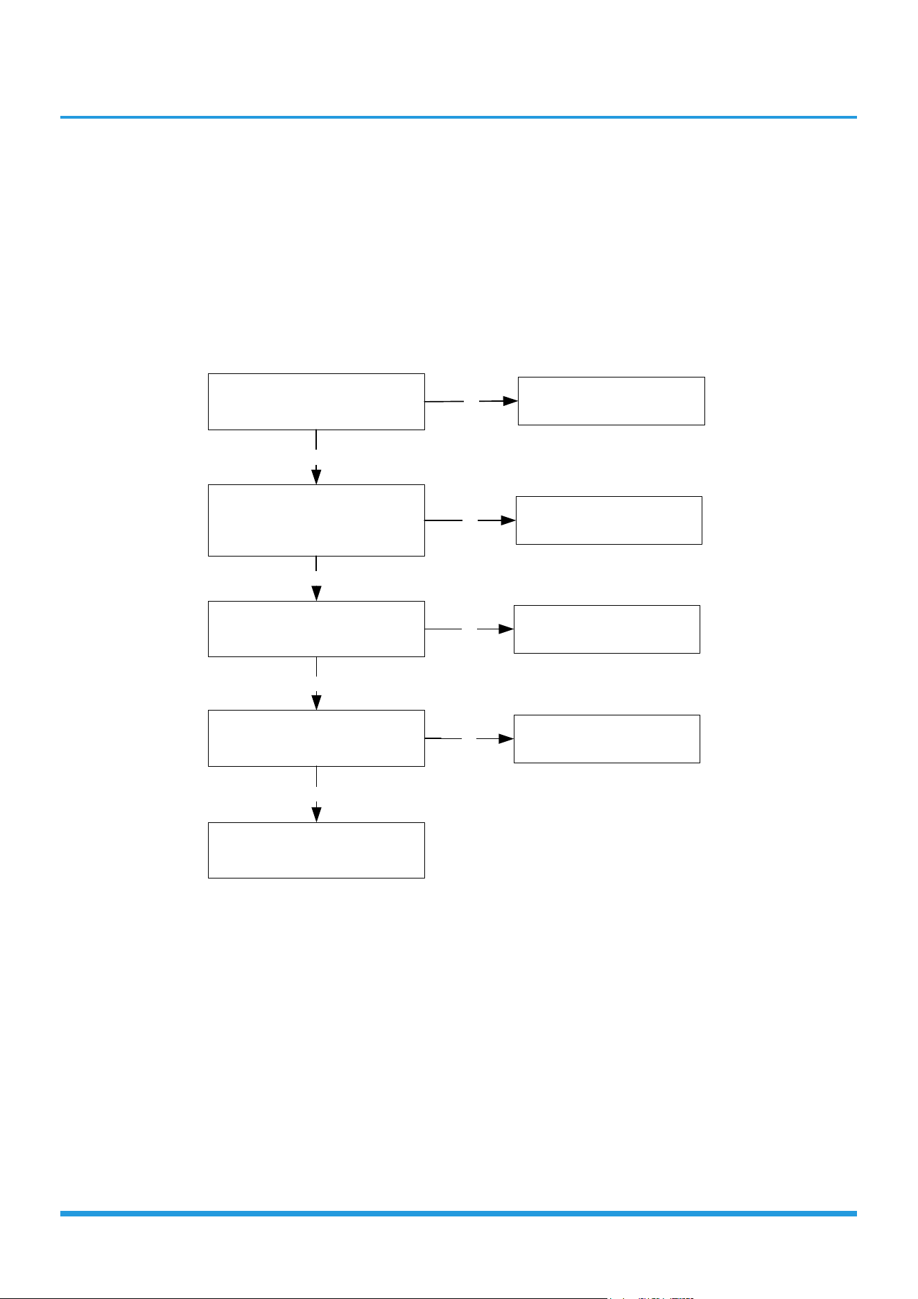
Troubleshooting
TS39: ODU compressor lack phase protection diagnosis and solution
Description: When the three-phase sampling current of the compressor is abnormal, especially when the current of one
or more phases is always small and almost 0, the LED displays the failure code
Recommended parts to prepare:
• Connection wire
• Compressor
• Outdoor PCB
Troubleshooting and repair:
Check the compressor three-
phase output for obvious open
circuit
Power off,then restart the unit
2 minutes later.Is it still
displaying the error code
The unit operates
normally
Check both ends of
compressor connecting
line .Are all the connections
good?
Correct the connections
Check whether the three-
phase resistance of the
compressor is symmetrical
Replace the compressor
Yes
Yes
Yes
No
No
No
Replace the main PCB
No
Trouble is solved
Yes
Troubleshooting
TS40: ODU IR chip drive failure diagnosis and solution
Description: When the IR chip detects its own parameter error, the LED displays the failure code when power on.
Recommended parts to prepare:
• Inverter module PCB.
Troubleshooting and repair:
Power off,then restart the unit
2 minutes later.
Replace the inverter module
PCB.
Yes
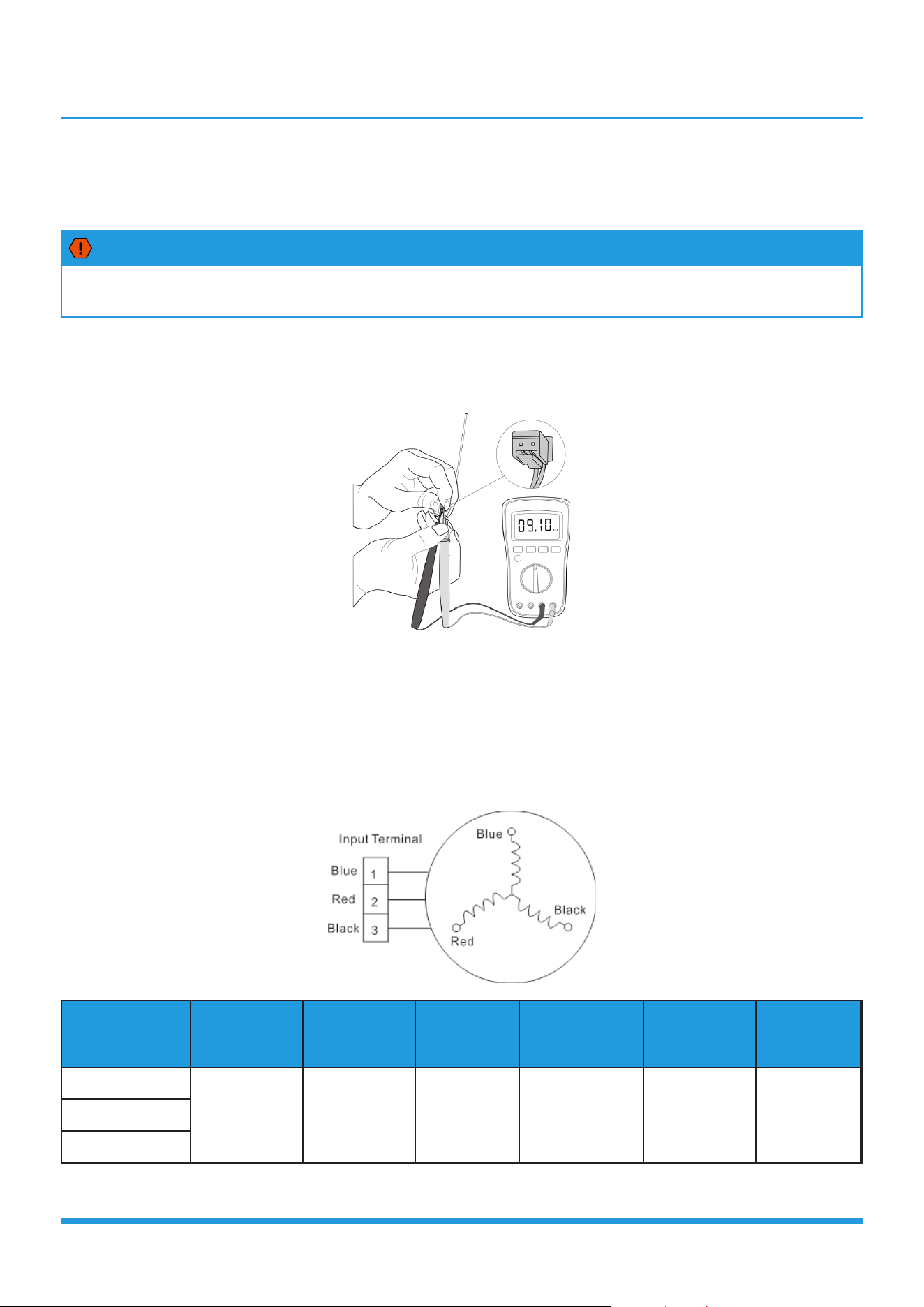
Troubleshooting
8. Check Procedures
8.1 Temperature Sensor Check
WARNING
Be sure to turn off all power supplies or disconnect all wires to avoid electric shock.
Operate after compressor and coil have returned to normal temperature in case of injury.
1. Disconnect the temperature sensor from PCB (Refer to Chapter 5&6. Indoor&Outdoor Unit Disassembly).
2. Measure the resistance value of the sensor using a multi-meter.
3. Check corresponding temperature sensor resistance value table (Refer to Chapter 8. Appendix).
Note: The picture and the value are only for reference, actual condition and specific value may vary.
8.2 Compressor Check
1. Disconnect the compressor power cord from outdoor PCB (Refer to Chapter 6. Outdoor Unit Disassembly)).
2. Measure the resistance value of each winding using a multi-meter.
3. Check the resistance value of each winding in the following table.
Resistance Value KSK89D53UEZ KSK89D29UEZD KSN98D22UFZ
KSK103D33UEZ3
KSK103D33UEZ3(MD)
KBK103D33UEZ3
KSK103D32UEZ31
KTN150D30UFZA
KTN150D30SFZA
Blue-Red
2.35Ω 1.99Ω 1.57Ω 2.13Ω 4.06Ω 1.02ΩBlue-Black
Red-Black
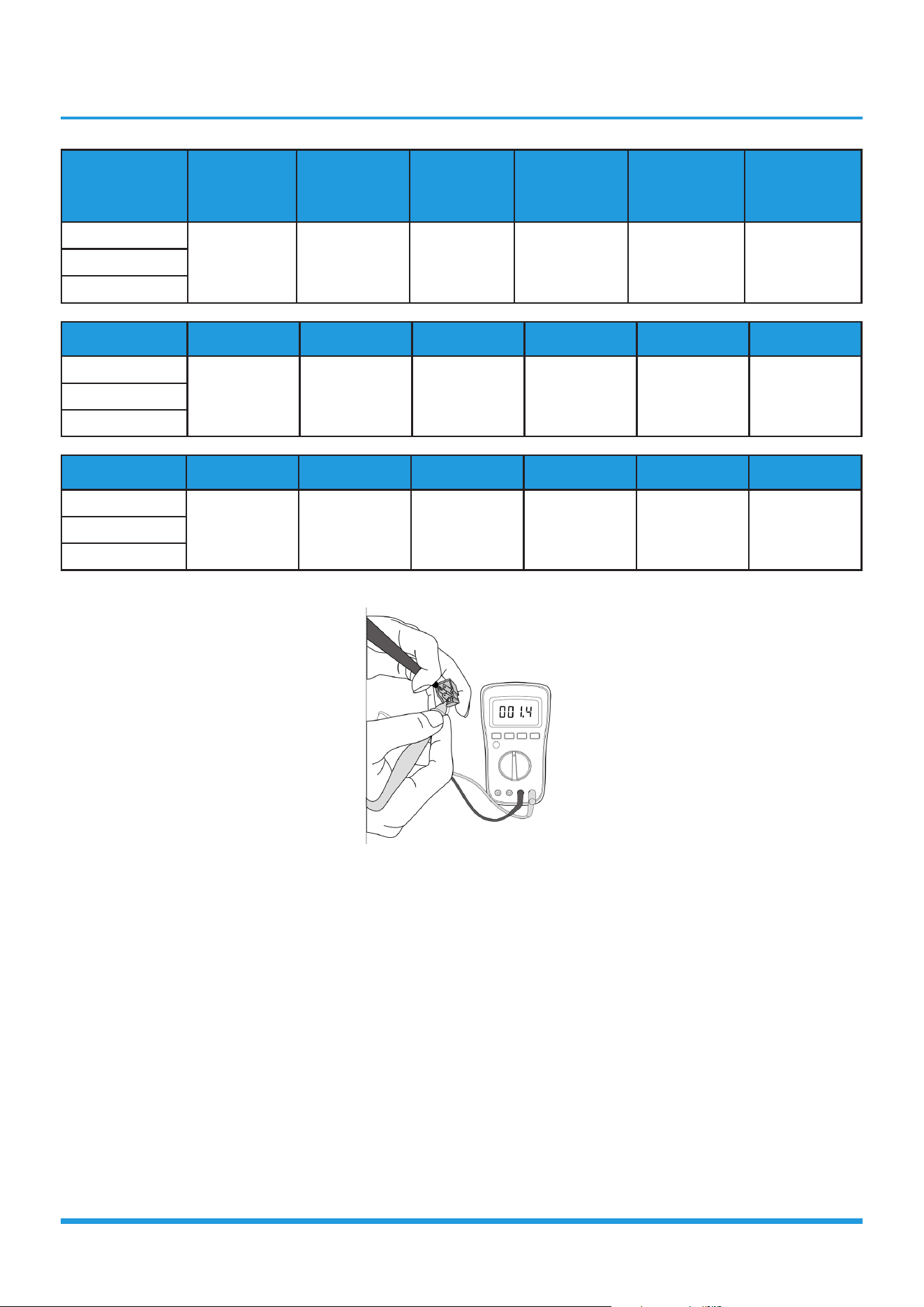
Troubleshooting
Resistance Value KSM135D23UFZ KTN110D42UFZ KSN140D21UFZ KTM140D78UFZ3
KTF235D22UMT
ATF235D22TMT
KTF250D22UMT
KTM240D46UKT2
Blue-Red
1.72Ω 1.82Ω 1.28Ω 1.5Ω 0.75Ω 1.04ΩBlue-Black
Red-Black
Resistance Value KSN140D58UFZ KTM240D43UKT KSN98D64UFZ3 ASN140D35TFZ KTF420D62UNT ASN108D22TEZ
Blue-Red
1.86Ω 1.03Ω 2.7Ω 0.83Ω 0.86Ω 1.76ΩBlue-Black
Red-Black
Resistance Value KTM240D63SKT2 KTM240D57UMT DTN210D32UFZ KSN140D33UFZB3
KTM110D79UFZA3 GSD098XKUF7JV6B
Blue-Red
1.19Ω 0.62Ω 1.7Ω 1.68Ω 1.88Ω 2.83ΩBlue-Black
Red-Black
Note: The picture and the value are only for reference, actual condition and specific value may vary.
Troubleshooting
8.3 IPM Continuity Check
WARNING
Electricity remains in capacitors even when the power supply is off.
Ensure the capacitors are fully discharged before troubleshooting.
1. Turn off outdoor unit and disconnect power supply.
2. Discharge electrolytic capacitors and ensure all energy-storage unit has been discharged.
3. Disassemble outdoor PCB or disassemble IPM board.
4. Measure the resistance value between P and U(V, W, N); U(V, W) and N.
Digital tester Resistance value Digital tester Resistance value
(+)Red (-)Black
∞
(Several MΩ)
(+)Red (-)Black
∞
(Several MΩ)
P
N U
N
U V
V W
W -
Or test the conductivity of IPM with diode mode.
Needle-type Tester
Normal Value
Needle-type Tester
Normal Value
Red Black Red Black
P
U
Open-circuit N
U
0.3-0.5V
V V
W W
Needle-type Tester
Normal Value
Needle-type Tester
Normal Value
Black Red Black Red
P
U
0.3-0.5V N
U
Open-circuit
V V
W W
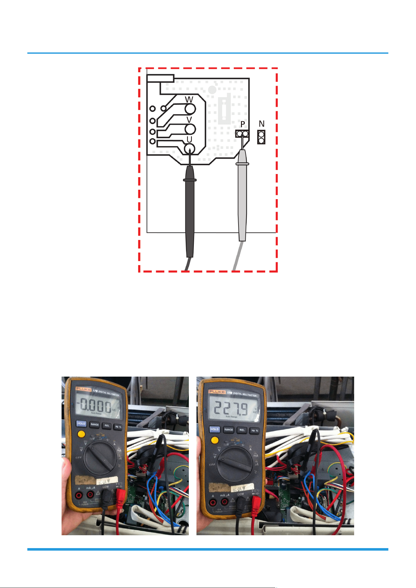
Troubleshooting
Note: The picture and the value are only for reference, actual condition and specific value may vary.
8.4 4-way Valve Check
1. Power on, use a digital tester to measure the voltage, when the unit operates in cooling, it is 0V. When the unit
operates in heating, it is about 230VAC.
If the value of the voltage is not in the range, the PCB must have problems and need to be replaced.
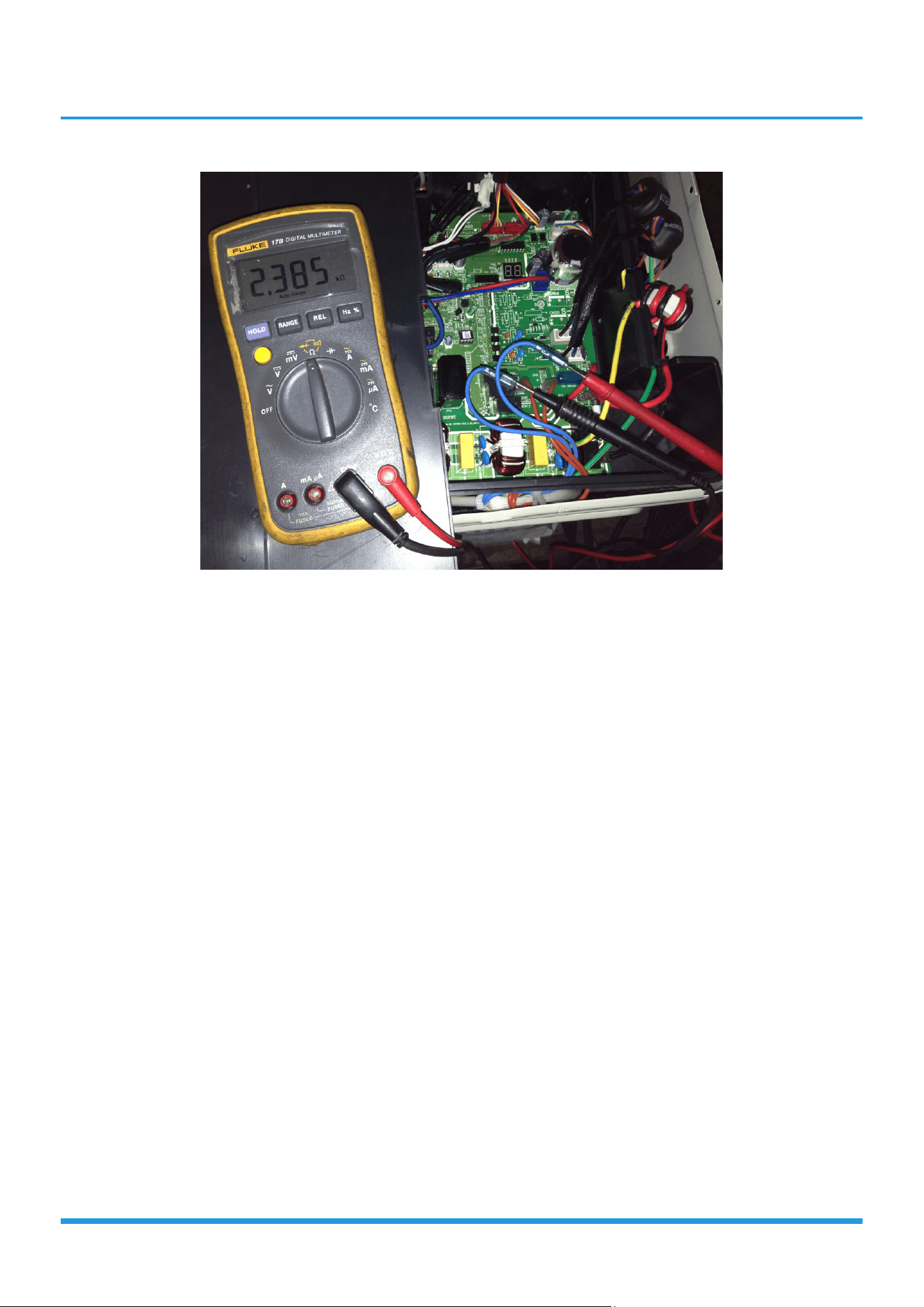
Troubleshooting
2 Turn off the power, use a digital tester to measure the resistance. The value should be 1.8~2.5 KΩ.
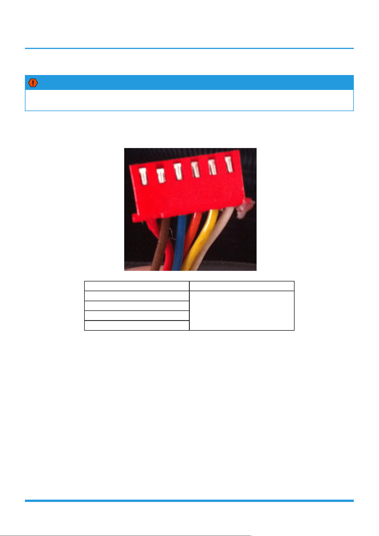
Troubleshooting
8.5 EXV Check
WARNING
Electricity remains in capacitors even when the power supply is off.
Ensure the capacitors are fully discharged before troubleshooting.
1. Disconnect the connector from outdoor PCB.
2. Measure the resistance value of each winding using a multi-meter.
3. Check the resistance value of each winding in the following table.
Color of lead winding Normal Value
Red- Blue
About 50Ω
Red - Yellow
Brown-Orange
Brown-White
6 5 4 3 2 1
Red Brown Blue Orange Yellow White

Contents
i) Temperature Sensor Resistance Value Table for TP (°C --K) ................................2
ii) Other Temperature Sensors Resistance Value Table (°C – K) ..............................3
iii) System Pressure Table ...........................................................................................4
Appendix
Appendix 2
i) Temperature Sensor Resistance Value Table for TP (°C --K)
°C °F K Ohm °C °F K Ohm °C °F K Ohm °C °F K Ohm
°C °F K Ohm °C °F K Ohm °C °F K Ohm °C °F K Ohm
-20 -4 542.7 20 68 68.66 60 140 13.59 100 212 3.702
-19 -2 511.9 21 70 65.62 61 142 13.11 101 214 3.595
-18 0 483 22 72 62.73 62 144 12.65 102 216 3.492
-17 1 455.9 23 73 59.98 63 145 12.21 103 217 3.392
-16 3 430.5 24 75 57.37 64 147 11.79 104 219 3.296
-15 5 406.7 25 77 54.89 65 149 11.38 105 221 3.203
-14 7 384.3 26 79 52.53 66 151 10.99 106 223 3.113
-13 9 363.3 27 81 50.28 67 153 10.61 107 225 3.025
-12 10 343.6 28 82 48.14 68 154 10.25 108 226 2.941
-11 12 325.1 29 84 46.11 69 156 9.902 109 228 2.86
-10 14 307.7 30 86 44.17 70 158 9.569 110 230 2.781
-9 16 291.3 31 88 42.33 71 160 9.248 111 232 2.704
-8 18 275.9 32 90 40.57 72 162 8.94 112 234 2.63
-7 19 261.4 33 91 38.89 73 163 8.643 113 235 2.559
-6 21 247.8 34 93 37.3 74 165 8.358 114 237 2.489
-5 23 234.9 35 95 35.78 75 167 8.084 115 239 2.422
-4 25 222.8 36 97 34.32 76 169 7.82 116 241 2.357
-3 27 211.4 37 99 32.94 77 171 7.566 117 243 2.294
-2 28 200.7 38 100 31.62 78 172 7.321 118 244 2.233
-1 30 190.5 39 102 30.36 79 174 7.086 119 246 2.174
0 32 180.9 40 104 29.15 80 176 6.859 120 248 2.117
1 34 171.9 41 106 28 81 178 6.641 121 250 2.061
2 36 163.3 42 108 26.9 82 180 6.43 122 252 2.007
3 37 155.2 43 109 25.86 83 181 6.228 123 253 1.955
4 39 147.6 44 111 24.85 84 183 6.033 124 255 1.905
5 41 140.4 45 113 23.89 85 185 5.844 125 257 1.856
6 43 133.5 46 115 22.89 86 187 5.663 126 259 1.808
7 45 127.1 47 117 22.1 87 189 5.488 127 261 1.762
8 46 121 48 118 21.26 88 190 5.32 128 262 1.717
9 48 115.2 49 120 20.46 89 192 5.157 129 264 1.674
10 50 109.8 50 122 19.69 90 194 5 130 266 1.632
11 52 104.6 51 124 18.96 91 196 4.849
12 54 99.69 52 126 18.26 92 198 4.703
13 55 95.05 53 127 17.58 93 199 4.562
14 57 90.66 54 129 16.94 94 201 4.426
15 59 86.49 55 131 16.32 95 203 4.294
16 61 82.54 56 133 15.73 96 205 4.167
17 63 78.79 57 135 15.16 97 207 4.045
18 64 75.24 58 136 14.62 98 208 3.927
19 66 71.86 59 138 14.09 99 210 3.812
Appendix 3
ii) Other Temperature Sensors Resistance Value Table (°C – K)
°C °F K Ohm °C °F K Ohm °C °F K Ohm °C °F K Ohm
-20 -4 115.266 20 68 12.6431 60 140 2.35774 100 212 0.62973
-19 -2 108.146 21 70 12.0561 61 142 2.27249 101 214 0.61148
-18 0 101.517 22 72 11.5 62 144 2.19073 102 216 0.59386
-17 1 96.3423 23 73 10.9731 63 145 2.11241 103 217 0.57683
-16 3 89.5865 24 75 10.4736 64 147 2.03732 104 219 0.56038
-15 5 84.219 25 77 10 65 149 1.96532 105 221 0.54448
-14 7 79.311 26 79 9.55074 66 151 1.89627 106 223 0.52912
-13 9 74.536 27 81 9.12445 67 153 1.83003 107 225 0.51426
-12 10 70.1698 28 82 8.71983 68 154 1.76647 108 226 0.49989
-11 12 66.0898 29 84 8.33566 69 156 1.70547 109 228 0.486
-10 14 62.2756 30 86 7.97078 70 158 1.64691 110 230 0.47256
-9 16 58.7079 31 88 7.62411 71 160 1.59068 111 232 0.45957
-8 18 56.3694 32 90 7.29464 72 162 1.53668 112 234 0.44699
-7 19 52.2438 33 91 6.98142 73 163 1.48481 113 235 0.43482
-6 21 49.3161 34 93 6.68355 74 165 1.43498 114 237 0.42304
-5 23 46.5725 35 95 6.40021 75 167 1.38703 115 239 0.41164
-4 25 44 36 97 6.13059 76 169 1.34105 116 241 0.4006
-3 27 41.5878 37 99 5.87359 77 171 1.29078 117 243 0.38991
-2 28 39.8239 38 100 5.62961 78 172 1.25423 118 244 0.37956
-1 30 37.1988 39 102 5.39689 79 174 1.2133 119 246 0.36954
0 32 35.2024 40 104 5.17519 80 176 1.17393 120 248 0.35982
1 34 33.3269 41 106 4.96392 81 178 1.13604 121 250 0.35042
2 36 31.5635 42 108 4.76253 82 180 1.09958 122 252 0.3413
3 37 29.9058 43 109 4.5705 83 181 1.06448 123 253 0.33246
4 39 28.3459 44 111 4.38736 84 183 1.03069 124 255 0.3239
5 41 26.8778 45 113 4.21263 85 185 0.99815 125 257 0.31559
6 43 25.4954 46 115 4.04589 86 187 0.96681 126 259 0.30754
7 45 24.1932 47 117 3.88673 87 189 0.93662 127 261 0.29974
8 46 22.5662 48 118 3.73476 88 190 0.90753 128 262 0.29216
9 48 21.8094 49 120 3.58962 89 192 0.8795 129 264 0.28482
10 50 20.7184 50 122 3.45097 90 194 0.85248 130 266 0.2777
11 52 19.6891 51 124 3.31847 91 196 0.82643 131 268 0.27078
12 54 18.7177 52 126 3.19183 92 198 0.80132 132 270 0.26408
13 55 17.8005 53 127 3.07075 93 199 0.77709 133 271 0.25757
14 57 16.9341 54 129 2.95896 94 201 0.75373 134 273 0.25125
15 59 16.1156 55 131 2.84421 95 203 0.73119 135 275 0.24512
16 61 15.3418 56 133 2.73823 96 205 0.70944 136 277 0.23916
17 63 14.6181 57 135 2.63682 97 207 0.68844 137 279 0.23338
18 64 13.918 58 136 2.53973 98 208 0.66818 138 280 0.22776
19 66 13.2631 59 138 2.44677 99 210 0.64862 139 282 0.22231
Appendix 4
iii) System Pressure Table-R454B
Pressure Temperature Pressure Temperature
Kpa bar PSI °C °F Kpa bar PSI °C °F
58.196 0.58 8.44 -60 -76 935.23 9.35 135.64 8 46.4
61.517 0.62 8.92 -59 -74.2 963.75 9.64 139.78 9 48.2
64.988 0.65 9.43 -58 -72.4 992.93 9.93 144.01 10 50
68.615 0.69 9.95 -57 -70.6 1022.8 10.23 148.34 11 51.8
72.402 0.72 10.50 -56 -68.8 1053.3 10.53 152.76 12 53.6
76.354 0.76 11.07 -55 -67 1084.5 10.85 157.29 13 55.4
80.478 0.80 11.67 -54 -65.2 1116.4 11.16 161.91 14 57.2
84.776 0.85 12.30 -53 -63.4 1149 11.49 166.64 15 59
89.256 0.89 12.95 -52 -61.6 1182.3 11.82 171.47 16 60.8
93.923 0.94 13.62 -51 -59.8 1216.3 12.16 176.40 17 62.6
98.781 0.99 14.33 -50 -58 1251.1 12.51 181.45 18 64.4
103.84 1.04 15.06 -49 -56.2 1286.6 12.87 186.60 19 66.2
109.1 1.09 15.82 -48 -54.4 1322.8 13.23 191.85 20 68
114.56 1.15 16.61 -47 -52.6 1359.9 13.60 197.23 21 69.8
120.25 1.20 17.44 -46 -50.8 1397.7 13.98 202.71 22 71.6
126.15 1.26 18.30 -45 -49 1436.3 14.36 208.31 23 73.4
132.28 1.32 19.18 -44 -47.2 1475.7 14.76 214.02 24 75.2
138.64 1.39 20.11 -43 -45.4 1515.9 15.16 219.85 25 77
145.24 1.45 21.06 -42 -43.6 1557 15.57 225.82 26 78.8
152.09 1.52 22.06 -41 -41.8 1598.9 15.99 231.89 27 80.6
159.18 1.59 23.09 -40 -40 1641.6 16.42 238.09 28 82.4
166.54 1.67 24.15 -39 -38.2 1685.2 16.85 244.41 29 84.2
174.15 1.74 25.26 -38 -36.4 1729.7 17.30 250.86 30 86
182.04 1.82 26.40 -37 -34.6 1775 17.75 257.43 31 87.8
190.2 1.90 27.59 -36 -32.8 1821.3 18.21 264.15 32 89.6
198.65 1.99 28.81 -35 -31 1868.4 18.68 270.98 33 91.4
207.39 2.07 30.08 -34 -29.2 1916.5 19.17 277.95 34 93.2
216.42 2.16 31.39 -33 -27.4 1965.6 19.66 285.08 35 95
225.76 2.26 32.74 -32 -25.6 2015.5 20.16 292.31 36 96.8
235.41 2.35 34.14 -31 -23.8 2066.5 20.67 299.71 37 98.6
245.37 2.45 35.59 -30 -22 2118.4 21.18 307.24 38 100.4
255.67 2.56 37.08 -29 -20.2 2171.3 21.71 314.91 39 102.2
266.29 2.66 38.62 -28 -18.4 2225.2 22.25 322.73 40 104
277.25 2.77 40.21 -27 -16.6 2280.2 22.80 330.70 41 105.8
288.56 2.89 41.85 -26 -14.8 2336.1 23.36 338.81 42 107.6
300.22 3.00 43.54 -25 -13 2393.2 23.93 347.09 43 109.4
312.24 3.12 45.28 -24 -11.2 2451.3 24.51 355.52 44 111.2
324.63 3.25 47.08 -23 -9.4 2510.4 25.10 364.09 45 113
337.39 3.37 48.93 -22 -7.6 2570.7 25.71 372.84 46 114.8
350.54 3.51 50.84 -21 -5.8 2632.1 26.32 381.74 47 116.6
364.08 3.64 52.80 -20 -4 2694.7 26.95 390.82 48 118.4
378.02 3.78 54.83 -19 -2.2 2758.3 27.58 400.04 49 120.2
392.37 3.92 56.91 -18 -0.4 2823.2 28.23 409.46 50 122
407.13 4.07 59.05 -17 1.4 2889.3 28.89 419.04 51 123.8
Appendix 5
422.31 4.22 61.25 -16 3.2 2956.5 29.57 428.79 52 125.6
437.92 4.38 63.51 -15 5 3025 30.25 438.72 53 127.4
453.98 4.54 65.84 -14 6.8 3094.7 30.95 448.83 54 129.2
470.47 4.70 68.23 -13 8.6 3165.7 31.66 459.13 55 131
487.43 4.87 70.69 -12 10.4 3238.1 32.38 469.63 56 132.8
504.84 5.05 73.22 -11 12.2 3311.7 33.12 480.30 57 134.6
522.73 5.23 75.81 -10 14 3386.7 33.87 491.18 58 136.4
541.1 5.41 78.48 -9 15.8 3463 34.63 502.25 59 138.2
559.95 5.60 81.21 -8 17.6 3540.7 35.41 513.52 60 140
579.31 5.79 84.02 -7 19.4 3619.9 36.20 525.00 61 141.8
599.16 5.99 86.90 -6 21.2 3700.5 37.01 536.69 62 143.6
619.54 6.20 89.85 -5 23 3782.7 37.83 548.61 63 145.4
640.43 6.40 92.88 -4 24.8 3866.3 38.66 560.74 64 147.2
661.86 6.62 95.99 -3 26.6 3951.5 39.52 573.10 65 149
683.82 6.84 99.18 -2 28.4 4038.3 40.38 585.69 66 150.8
706.34 7.06 102.44 -1 30.2 4126.8 41.27 598.52 67 152.6
729.41 7.29 105.79 0 32 4217 42.17 611.60 68 154.4
753.06 7.53 109.22 1 33.8 4309 43.09 624.95 69 156.2
777.28 7.77 112.73 2 35.6 4402.9 44.03 638.56 70 158
802.08 8.02 116.33 3 37.4 4498.7 44.99 652.46 71 159.8
827.48 8.27 120.01 4 39.2 4596.5 45.97 666.64 72 161.6
853.49 8.53 123.78 5 41 4696.5 46.97 681.15 73 163.4
880.11 8.80 127.64 6 42.8 4798.9 47.99 696.00 74 165.2
907.35 9.07 131.60 7 44.6 4904.1 49.04 711.25 75 167