Whole House
SimplySoft
®
Water Softener
40,000 Grains & 60,000 Grains
Owner’s Manual
WH-SF40 AND WH-SF60

TABLE OF CONTENTS
Box Contents & System Conguration ............................................................................ 1-2
Precautions/Safeguards ........................................................................................................3
Installation Steps ..............................................................................................................4-12
System Maintenance ......................................................................................................13-16
Troubleshooting Guide ....................................................................................................... 17
Product Specications & Performance............................................................................. 18
Warranty ............................................................................................................................... 19
Water for Life
®
Program ..................................................................................................... 20
*Potential savings based on Water Quality Research Foundation Battelle Institution Study.
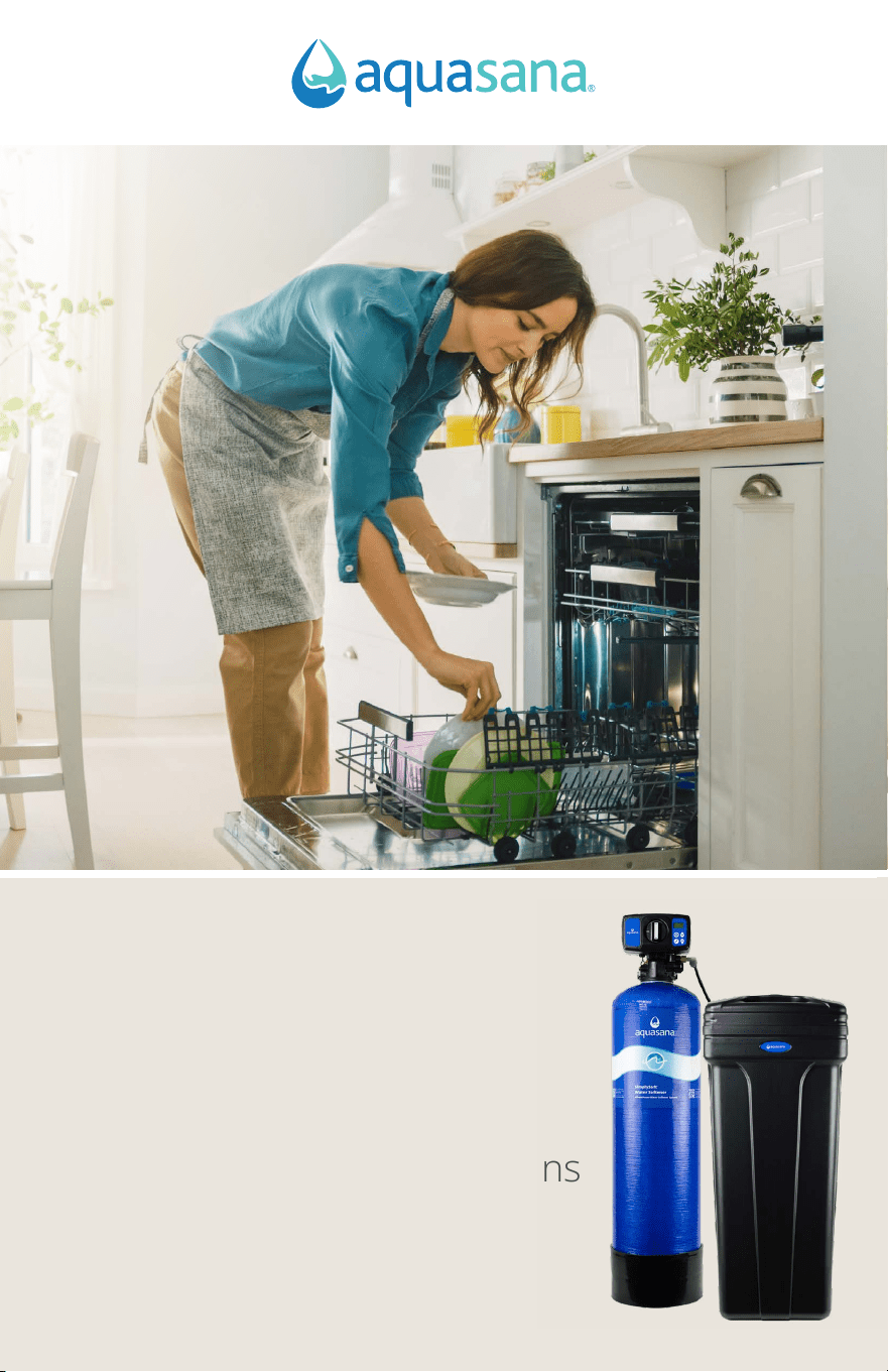
Experience the luxury of soft water. Your new Aquasana SimplySoft
®
Water
Softener was expertly engineered to reduce hard water minerals, ensuring
soft, scale-free water throughout your home.
Our SimplySoft
®
softeners help you save up to $497 annually* by improving
appliance eciency, reducing repairs, and cutting soap costs. Protect your
pipes and appliances, get spotless dishes and shower doors, prevent wear
and fading in your clothing and linens, and enjoy soft water that’s gentle on
skin and hair — all by reducing hard water in your home.
WH-SF40 AND WH-SF60
Whole House
SimplySoft
®
Water Softener
Next >
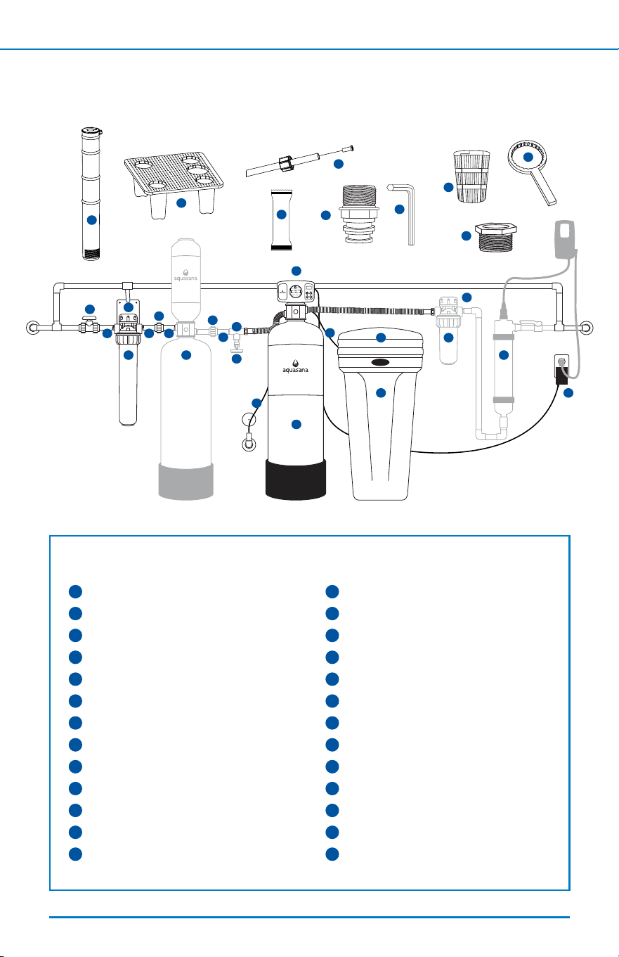
BOX CONTENTS & SYSTEM CONFIGURATION
1
If you have added components to your Whole House
SimplySoft
®
Water Softener, note the correct sequencing below.
< Back To Table of Contents Next >
1
SimplySoft
®
Pressure Tank
2
Control Valve
3
Transformer
4
Brine Tank
5
Brine Tank Lid
6
Grid Plate & Feet (4)
7
Brine Tubing & Insert
8
Brine Well
9
Drain Line & Clamp
10
Grease Packet
11
1" Straight Threaded Fittings (2)
12
Allen Wrench
13
Upper Basket
14
Pre-Filter
15
Post-Filter
16
Plastic Wrench
17
Filter Support Brackets
18
Shut-O Valve
19
Slip Unions
20
2.5" TOE Nipples
21
3" Smooth Nipple
22
1"-3/4" Reducer Bushings (2)
23
Brass Drain Valve
24
PVC Tee
25
Rhino
®
Filter Tank
26
UV Filter
Softer, scale-free water from every tap in your home.
2
18
19
19
21
23
24
9
1
7
13
5 15
17
34
25 26
19
17
14
20 20
22
7
16
6
8
10
12
11
The following components may vary
based on the purchased conguration.

• 80 lbs of water softener salt (2 bags)
• 2 adjustable wrenches
• Drill
• Channel locks
• Pipe cutter
• NSF certied PVC primer and glue
• NSF certied plumber’s tape
• 5 gallon bucket
Tools recommended for installation:
>> Click here to view the SimplySoft
®
Water Softener installation video.
• Copper wire & grounding clamps (if
copper pipes are present)
• Pex tubing, crimp rings, and cutter
• Garden hose
Optional components:
< Back To Table of Contents Next >
Box contents may be packaged in multiple boxes.
Before beginning installation, please ensure all parts listed are present.
If any part is missing or damaged, do not attempt to install the system.
Before beginning installation, ensure you have a copy of your most recent water test
results for your home’s water hardness. This is required when setting the controller.
Not all congurations can be addressed in this Owner’s Manual. Appearance and
quanitity of parts/components may vary depending on the time of purchase.
Please contact Customer Support for replacement parts at 866-662-6885.
BOX CONTENTS & SYSTEM CONFIGURATION
2

• For all installations: Due to the varieties of home design, not all congurations
can be addressed in this guide. Anticipate the need for additional parts and
pieces including but not limited to pex tubing, clamps, and mounting screws to
install unit properly (available at a local home improvement store or through
your plumbing contractor).
• Installation of the system must comply with existing state and local plumbing
and electrical codes.
• General plumbing knowledge is required for installation. Installation by a
licensed plumber or certied installer is recommended.
• This system is not intended for treating water that is microbiologically unsafe or
of unknown quality without adequate disinfection before or after the system.
• Do not install this softener where the line pressure may exceed 125 psi. The
operating pressure range for this softener is between 30 psi – 125 psi. In areas
with high pressure (over 80 psi), we recommend installing a pressure reducing
valve ahead of the softener.
• Install on cold water lines only (40° - 110°F).
• It is recommended your system be installed indoors and out of direct sunlight.
Prolonged exposure to light can weaken plastic components, resulting in housing
failure. If this is not possible and the system is outdoors or in a sunny area, the
unit must be protected from both direct sunlight and freezing temperatures. If
the unit is installed outside, quarterly sanitization is strongly recommended.
• Unit must be installed in an area where the main water line enters your home,
before connecting to the water heater. DO NOT install after a water heater or
on the hot water line.
• DO NOT install the system on its side.
• Pick an appropriate installation location where if the system or any connection
thereto should leak, the resulting ow of water will not cause damage to the
surrounding area.
• NSF certied plumber’s tape (thread sealing tape) is the only sealer that can be
used on threaded ttings.
• Properly tighten all ttings to ensure a leak-free assembly.
• DO NOT use petroleum-based lubricant. Use only 100% silicone lubricant.
• DO NOT use pliers or pipe wrenches except when indicated. All plastic
connections should be hand tightened only.
2
NOTE: Installation could take 1-4 hours to complete. Plan accordingly
as you will be without water throughout the home during this time.
Precipitated minerals or sediment can cause damage to the seals and
pistons. If precipitated minerals or sediment are present in your water
supply this will be considered a harsh environment. The seals and
pistons would not be covered by warranty, stated or otherwise.
< Back To Table of Contents Next >
PRECAUTIONS/SAFEGUARDS
3
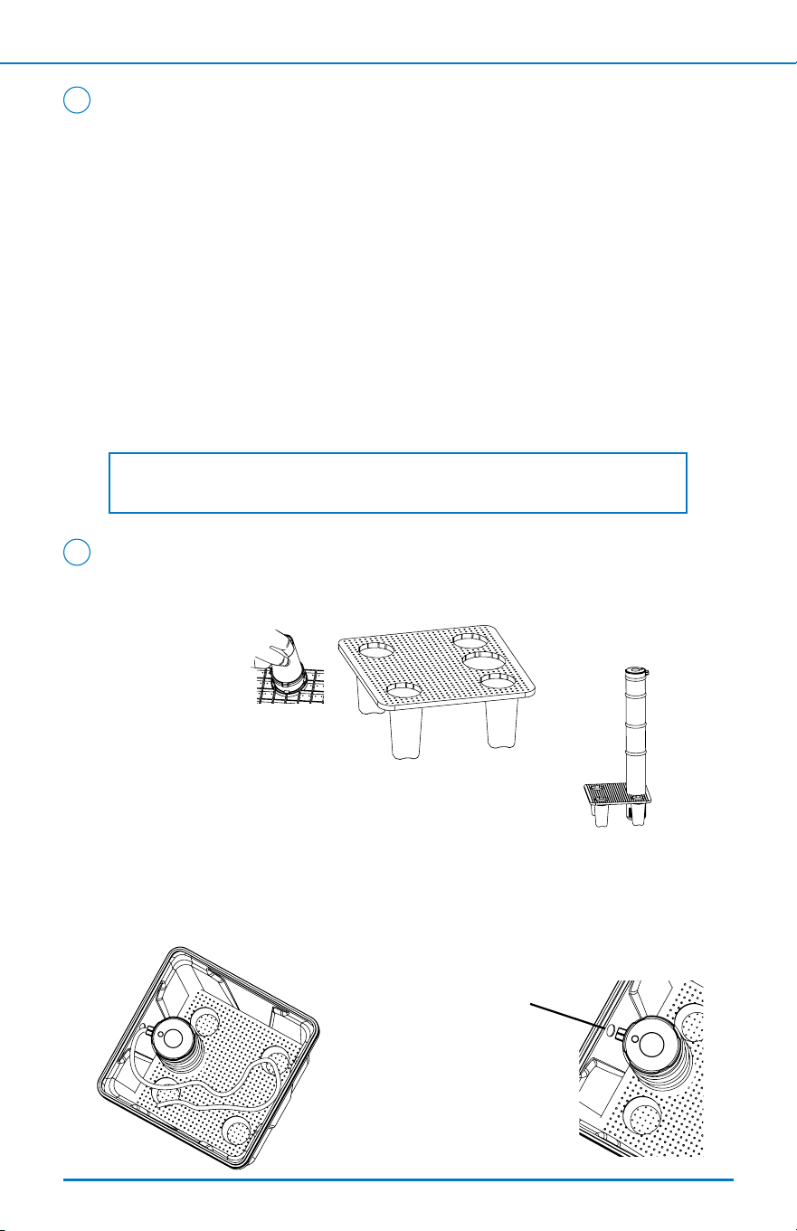
1. Attach the 4 brine legs to the grid plate. The legs will snap on to the
tabs of the plate making a ‘click’ sound.
2. Insert the brine well into the hole of the grid plate and
push through until it is even with the brine legs.
3. Place the brine grid with the brine well inside the brine tank so that
the nut tting faces the hole on the brine tank. The handle of the
brine tank should also align with the brine well. Then, press the grid
evenly inside the brine tank until the brine legs and the brine well
touch the bottom of the tank.
Assemble Brine Tank
2
Select Location
Consider the following when selecting where to install the system:
1. Outside taps used to water lawns and gardens should be isolated from
the water line required to supply untreated water to the inlet of the water
softener.
2. Location should be as close as possible to the water supply source.
3. Location should be as close as possible to an existing or pre-installed
drain location, and a 120 volt AC electrical outlet.
4. Softener should be installed before the water heater.
5. Ensure the system sits level.
6. Allow sucient space around the system for easy servicing.
1
NOTE: Check local plumbing codes requirements for use of check valve,
back-ow prevention, or vacuum breaker.
IMPORTANT: The hole in the
brine tank should line up with
the brine line as shown.
< Back To Table of Contents Next >
INSTALLATION STEPS
4
3
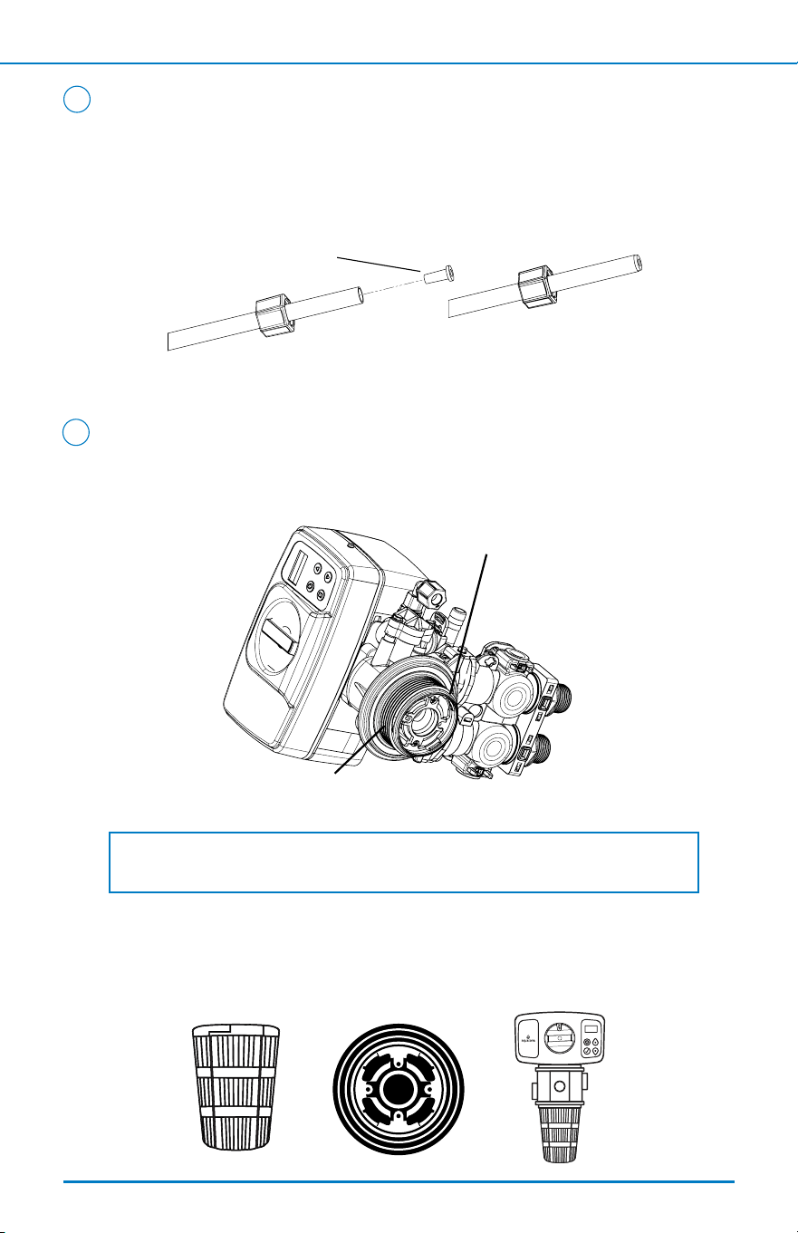
4. Ensure the attached tube stiener is inserted into the brine tube. Then,
take the brine tube and insert the nut and plastic sleeve as shown below.
Insert the tube in the brine well elbow and hand-tighten the nut. Pull
the opposite end of the brine tube through the hole on the brine tank to
prepare for installation.
5. Keep brine tank lid to the side until instructed to add salt.
Prepare Pressure Tank
1. Apply the supplied lubricant to the internal o-ring at the bottom of the
control valve. Apply lubricant to the larger o-ring on the bottom of the valve
that seals with the tank threads.
2. Attach the upper basket to the control valve. Do so by lining up recesses on
edge of upper basket with clips on the white retainer on the bottom of the
control valve. Insert the basket and rotate to the right to lock into position.
Assemble Brine Tank (cont. from previous page)
2
Insert sleeve
NOTE: Do not use petroleum-based lubricants as they will cause swelling of
the o-ring seals.
O-ring
Tank seal o-ring
< Back To Table of Contents Next >
INSTALLATION STEPS
5
Prepare Pressure Tank (cont. from previous page)
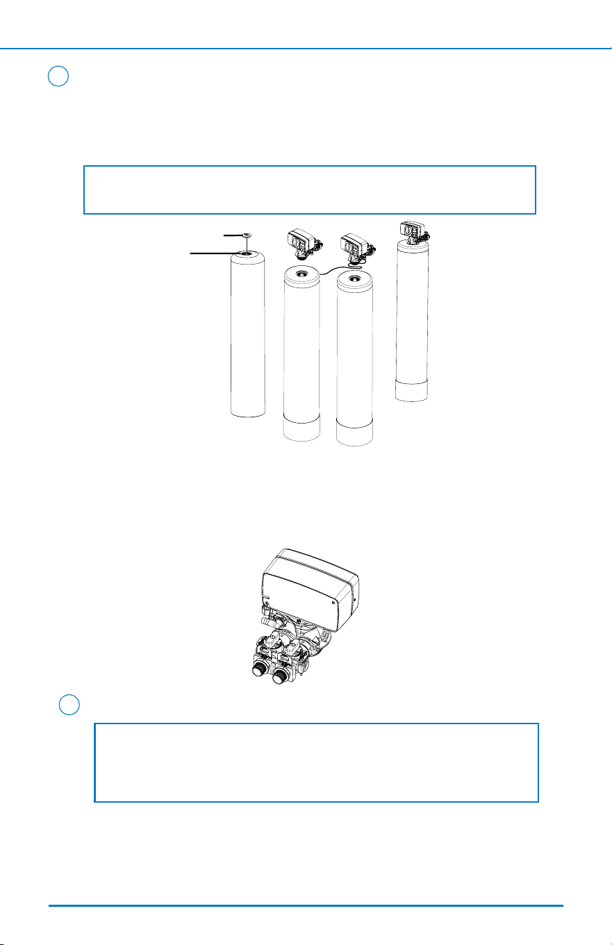
3. Remove the tape from the top of the riser tube. Carefully position the
control valve and basket over the riser tube, inserting riser into the
internal o-ring. Turn the control valve to the right into the threads of the
tank until secure.
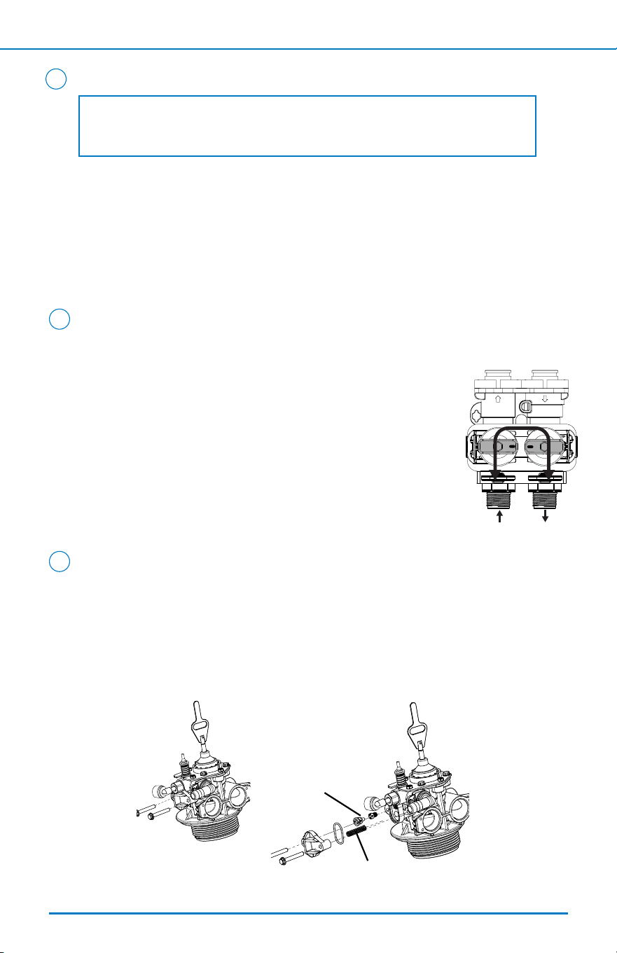
4. Wrap plumber’s tape around threaded ends of both ttings 3-4 times.
5. Apply the supplied lubricant to the attached o-rings on both ttings.
6. Connect both ttings to the bypass by removing the red clips, inserting
the ttings and reattaching the red clips to hold in place.
3
NOTE: Ensure the quick connect power cord is not yet connected to prevent
the cord getting caught between the threads of the tank and the valve.
D-tube
Unscrew spill cap
Ensure Spacing and Cut Pipes
If you have additional attachments and/or upgrades, please reference
those manuals before nal installation.
1. Turn o the main water source. Drain water from lines to relieve
pressure by turning on a faucet at the lowest elevation inside your
home.
4
NOTE: Pre-assemble all parts and dry-t the entire system to ensure
proper spacing and to conrm you have the necessary components for
installation. Reference system conguration image on page 1 to under the
system layout and connections.
< Back To Table of Contents Next >
INSTALLATION STEPS
6
Ensure Spacing and Cut Pipes (cont. from previous page)
2. Using a pipe cutter, cut into the main water supply line and catch any
remaining water in the 5 gallon bucket.
3. Measure distance for pre-lter and optional add-ons, and mark
accordingly.
4. Cut pipe along the marked sections from previous step and clean ends
of pipe. Ensure there are no burrs, sharp edges, or deep scratches.
Congure System
System conguration may vary. Instructions provided are for base
Aquasana install kit.
1. Fit pre-lter, pressure tank, brine tank, and any optional add-ons into
the system as this time.
2. Attach the pre-lter to your incoming water line.
3. Attach the lter wall bracket to the pre-lter housing with included
screws. Once this is complete, screw the support bracket to the wall.
4. Ensure all parts are owing through the “IN” port in the correct direction
of water ow.
5. Connect the threaded nipple from the pre-lter outlet to the union
attached to the pressure tank inlet.
6. Connect the threaded nipple from the pre-lter outlet to a union, and
from the union to the pressure tank inlet.
7. Once installation is complete, allow proper time for the glue to dry.
During this time, ensure all connections are tight.
5
NOTE: Additional materials may be needed to ensure pre-lter brackets
are supported and properly secured to the wall.
NOTE: Verify connection to the correct side of the pressure tank
connections indicated by the arrows on top of the valve. The INLET port is
on the side with the drain and brine lines. DO NOT PLUMB BACKWARDS.
4
NOTE: Cut tubing as straight as possible with a utility knife, or an
appropriate pipe cutter for copper, PVC, or PEX tubing.
< Back To Table of Contents Next >
INSTALLATION STEPS
7
NOTE: DO NOT cut more pipe than necessary. You can cut more pipe later
if needed.
Connect Brine Tank
1. Measure the brine tube from brine tank to brine elbow assembly on
side of control valve. Cut excess tubing as needed.
2. Remove the clip on the brine elbow assembly, if included, and push the
brine tube into the open port.
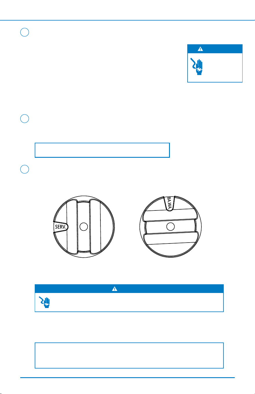
3. Using the included Allen key, place the system in the bypass position.
4. Slowly turn the main water supply on.
5. Turn on the nearest faucet and let water run until the water is free of
any air bubbles or foreign material resulting from the installation.
7
OPEN OPEN
CLOSE
OPEN OPEN
CLOSE
OPEN OPEN
CLOSE
SERVICE
INLET OUTLET
INLET OUTLET
BYPASS
6
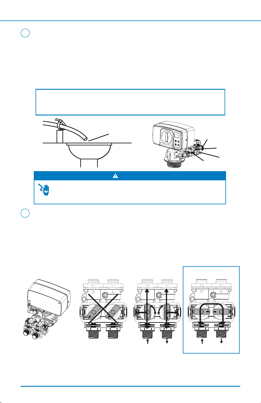
NOTE: The waste connections or drain outlet must be designed and
constructed to provide for connection to the sanitary waste system
through an air gap of 2 pipe diameters or 1”, whichever is larger.
WARNING
DO NOT insert drain line directly into a drain, sewer line, or trap. Always
allow an air gap between the drain line and the wastewater to prevent the
possibility of sewage being back-siphoned into the softener.
Connect the Drain Line
1. Attach the ½" drain hose to the drain line tting with provided
clamp. Tighten with screwdriver.
2. Run the drain line to the existing softener drain. Measure tubing
and cut excess as needed.
3. Complete any necessary plumbing to maintain a proper air gap.
< Back To Table of Contents Next >
INSTALLATION STEPS
8
1" Straight
Adapters
Brine Line
Drain Line
Bypass
Air Gap
Drain
Purge Air from the System
1. Manually turn the valve with the control knob to the backwash setting,
labeled BA.WA.
2. Open the bypass INLET slowly until there is a steady stream of water at
the drain.
3. With the bypass inlet now fully open, let the system run until all of the
air is purged and there is a steady stream of water at the drain.
10
NOTE: This step may take longer than the programmed backwash cycle time,
so unplug the power so that the valve will remain in the backwash position.
WARNING
Opening the bypass inlet too quickly may result in resin being expelled from
the unit and into the plumbing lines.
Add Water to the Brine Tank
Open the brine tank lid and ll with water until there is approximately 1”
of water above the grid plate.
9
NOTE: DO NOT add salt to the brine tank at this time.
Connect the Transformer
1. Connect the transformer to the system by plugging the
12 volt transformer into a 120 VAC 60 Hz outlet. Then,
connect the power supply to the control valve power
supply.
2. When the power is connected, the control screen will
show the following information in sequence:
Time
Remaining U.S. Gallons
8
WARNING
DO NOT use
an outlet that
is controlled by
a light switch.
< Back To Table of Contents Next >
INSTALLATION STEPS
9
Purge Air from the System (cont. from previous page)
4. If the power was disconnected in step 3, reconnect the power.
Manually turn the control knob to the right to the rell position,
labeled REFILL. Allow the system to rell at least twice by rotating
the control knob back around to REFILL until there is approximately
1" of water above the grid plate. Alternatively, water may be added
manually as in Step 9.
5. Allow the control knob to return to the service position, labeled SERV.
6. Slowly open the bypass OUTLET knob until fully open.
10
< Back To Table of Contents Next >
OPEN OPEN
CLOSE
OPEN OPEN
CLOSE
OPEN OPEN
CLOSE
SERVICE
INLET OUTLET
INLET OUTLET
BYPASS
INSTALLATION STEPS
10

Program the Control Valve
Compensated Hardness Calculation with Iron and Manganese Levels:
___ ppm Iron x 4 = ___ grains of hardness
___ ppm Manganese x 8 = ___ grains of hardness
Example: If Using Iron and Manganese Levels
Our water analysis states that our hardness is 15 gpg.
To this we add:
Iron = 0.5 ppm x 4 = 2.0 gpg
Manganese = 0.3 x 8 = 2.4 gpg which we round up to 3.0 gpg
We use the following hardness equation to derive our total hardness
number.
Hardness = 15 gpg + 2.0 (now called compensated iron) + 3.0 (compensated
Manganese) = 20 gpg
Enter 20 for total hardness when programming.
Example: If Only Using Hardness Level
Our water analysis states that our hardness is 14.55 gpg.
Enter 15 for total hardness when programming.
11
NOTE: You must have your ZIP code's water hardness level (in gpg) from
your city's most recent water report or have your water tested in order to
program the control valve. You are required to program the time of day, the
number of people living in the home, and the correct hardness setting. Iron
and maganese can be found on your water report.
INSTALLATION STEPS
11
< Back To Table of Contents Next >
11
12
INSTALLATION STEPS
12
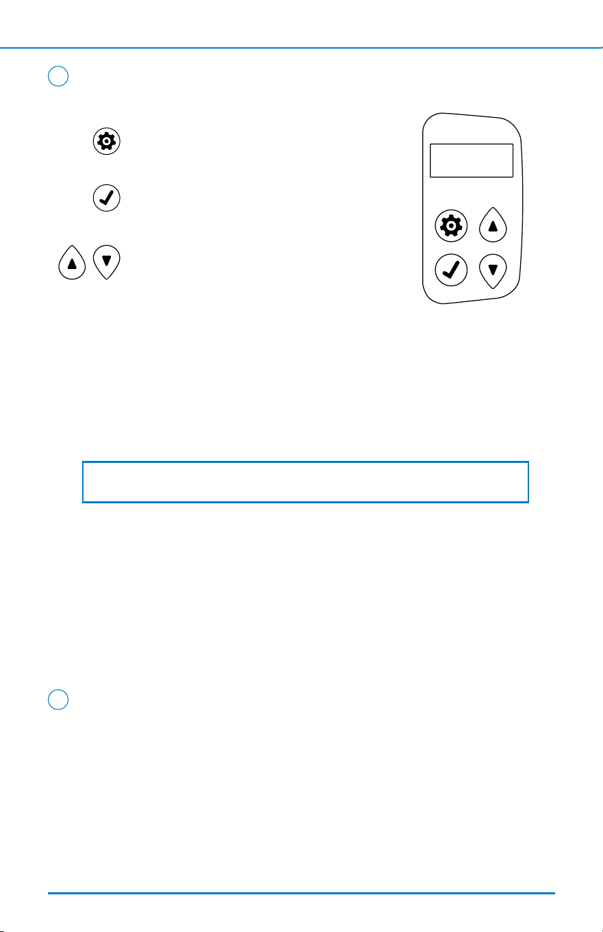
SELECT - This function is to accept the
values if changed and advance to the next
page in the menu.
UP/DOWN - These buttons are used to
increase or decrease the value of the
settings while in the programming mode.
SETTINGS - This function is to enter the
basic set up information required at the
time of installation.
Key Pad Conguration:
SETTINGS
SELECT
NOTE: When programming the hardness level, round up to the nearest
whole number.
< Back To Table of Contents Next >
Program the Control Valve (cont. from previous page)
Set Time of Day
1. Press SETTINGS key to advance to TIME OF DAY. TIME OF DAY will ash.
2. Press the UP or DOWN keys to adjust the TIME OF DAY. Press and hold the UP
or DOWN key to quickly advance the hour and minutes. When desired time is
displayed, press SELECT.
Set Hardness
1. To advance to the hardness setting, press SELECT. HARDNESS will ash.
2. Press the UP or DOWN keys to adjust the hardness. When desired hardness is
displayed, press SELECT.
Set Number of People
1. To advance to the people setting, press SELECT. PEOPLE will ash.
2. When desired number of people is displayed, press SELECT to complete
programming.
Add Salt to the Brine Tank
1. Open the lid of the brine tank and add 80-100 lbs of water softener salt.
Replace the brine tank lid.
2. Final installation is complete. The system will automatically ll the water to the
correct level when it regenerates.
Cleaning
1. The exterior of your system can be cleaned with warm, soapy water.
Do not use any abrasive solution.
2. Rinse well with clean water.
Manually Regenerate
To regenerate immediately, turn the center knob clockwise to BA.
WA (Backwash) position.
Alternatively, a regeneration can be started
using the buttons on the control panel.
1. Press and hold SELECT for 3 seconds.
2. Use UP or Down arrow to select to start the regeneration the coming
night (DELAY) or immediately (IMMEDIAT).
3. Conrm selection by pressing SETTINGS.
During a regeneration, you can manually advance to the next cycle by
pressing the SELECT button if you want to advance without waiting for
the timer for diagnostics purposes only.
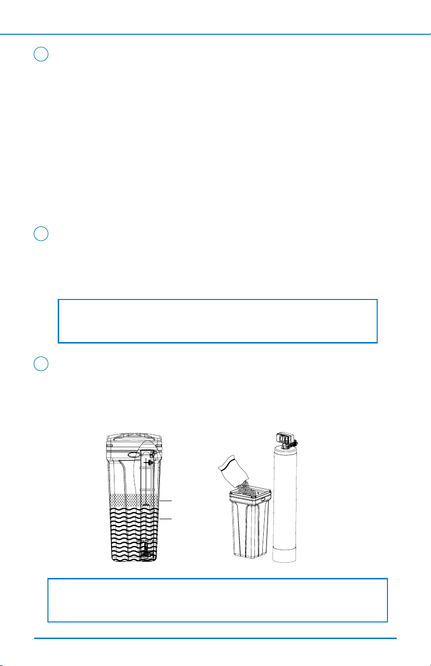
Adding Salt to the Brine Tank
1. Check the salt level regularly.
2. Open the lid of the brine tank and add 80-100 lbs of water softener
salt. Salt level must be above the brine water level.
2
1
3
NOTE: Never use chemical cleaning products on the system’s exterior
surface as they may cause damage.
NOTE: Use only clean salt intended for water softener use, such as crystal, pellet,
nugget, or button. DO NOT use natural rock salt. DO NOT mix types of salt.
Salt
Water
SYSTEM MAINTENANCE
13
< Back To Table of Contents Next >
Salt Bridging
Humidity or poor-quality salt may create a cavity between the water and the
salt. This action, known as 'bridging,' prevents the brine solution from being
made, and prevents your water from being conditioned. If you suspect salt
bridging because of lack of soft water or salt is not being consumed, follow
the below steps:
1. Use a rubber mallet to pound on the outside of the plastic brine tank or
pour a small amount of warm water around the inside edges of the salt
tank to break up the bridging.
2. Allow 4 hours to produce a brine solution, then manually regenerate the system.
3. Allow the system to use up any remaining salt and then thoroughly clean
out the brine tank.
4
Adding Water Softener Cleaner (for indoor installations ONLY)
6
NOTE: For optimal performance and to extend the life of your water
softener, it is recommended to use this cleaner (for indoor installations) or
sanitize your softener (for outdoor installations) every 3 months. Do not use
this cleaner for outdoor installations.
Cleaning the Brine Tank
1. Brine tanks must be cleaned every 2-3 years to remove undissolved
salt sludge.
2. After cleaning, use the original start-up instructions to restart system.
5
SYSTEM MAINTENANCE
14
< Back To Table of Contents Next >
1. Pour half the bottle (16 ounces) directly into the brine well of your
system. If your softener has no brine well, pour directly into the salt
tank when the salt is low.
2. Manually regenerate the softener immediately. Repeat regeneration if
taste, odor, or discoloration is detected in the discharge.
3. Next, run the cold, soft water tap nearest the softener.
Click here to purchase Aquasana Water Softener Cleaner,
view cleaner instructions, and learn more.
Service the Control Valve
Before servicing, you will need to:
1. Shut the water supply to the system o and put the
softener in the BYPASS position.
2. Relieve the water pressure in the softener. Do so by
turning the control into the BACKWASH momentarily.
3. Return the control to the SERVICE position.
4. Unplug the electrical cord.
5. Disconnect the drain line connection.
Clean Injector Assembly
1. After completing the above steps for servicing the control valve, reduce
the water pressure by opening the nearest cold water faucet.
2. Using a screwdriver, remove the 2 screws holding the injector cover to
the control valve body.
3. Carefully remove the cover and disassemble.
8
9
SYSTEM MAINTENANCE
15
< Back To Table of Contents Next >
OPEN OPEN
CLOSE
OPEN OPEN
CLOSE
OPEN OPEN
CLOSE
SERVICE
INLET OUTLET
INLET OUTLET
BYPASS
7
NOTE: This appliance may be disinfected with 5.25% sodium hypochlorite,
which is the active ingredient in household chlorine bleach. For outdoor
installations, this should be done every 3 months.
Sanitizing Your Softener
1. Add 4.0 uid ounces of chlorine bleach solution to the brine well of the
brine cabinet.
2. Start a manual regeneration as described in System Maintenance Step 1.
3. Once regeneration cycle is complete, run the cold, soft water tap
nearest to the softener until no chlorine smell remains. The system is
now ready to use.
Injector Screen
Injectors

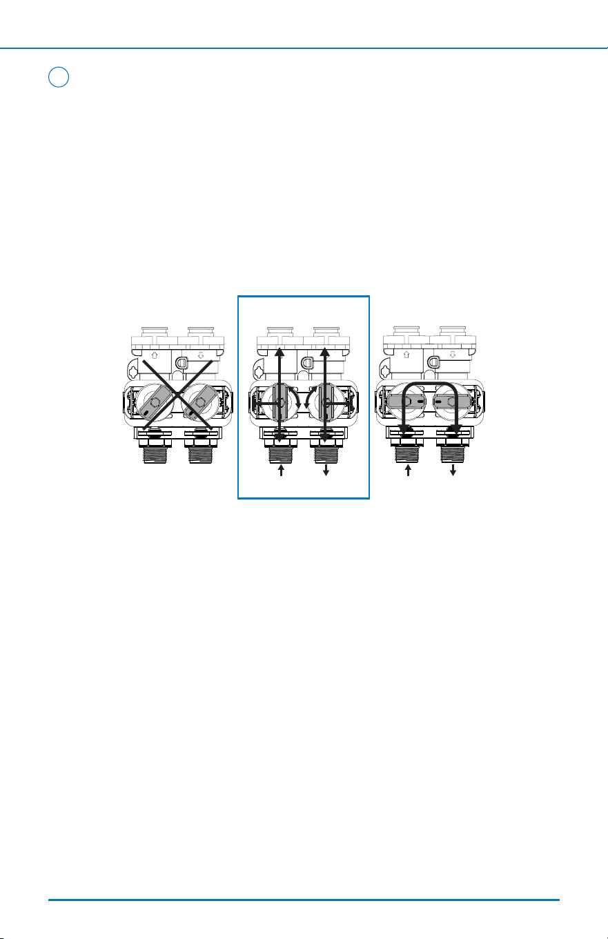
MANUAL WATER BYPASS
In case of an emergency or to perform softener maintenance, isolate your system
from the main water supply using the bypass valve, located at the back of the
control valve.
In normal operation, the bypass is set to OPEN with the ON/OFF knobs in line
with the INLET and OUTLET pipes.
To isolate the system, rotate the knobs as indicated to the CLOSE position
until they lock. You can continue to use your water, however the water will be
untreated.
To resume service, OPEN the bypass valve by rotating the knobs back to the
SERVICE position.
NOTE: Ensure bypass knobs are completely open. If not, untreated water
may enter through the valve.
SYSTEM MAINTENANCE
16
< Back To Table of Contents Next >
Clean Injector Assembly (cont. from previous page)
4. Using a screwdriver, carefully unscrew the injector nozzle from the valve body.
5. Using a screwdriver, carefully unscrew the injector throat.
6. Flush all parts with water, including the injector screen.
7. Use a mild acid, such as vinegar or Pro Rust Out, to clean the small holes in the
nozzle and throat.
8. Reassemble by reversing the steps.
9
Issue Resolution
Component is missing or
arrived damaged
Call Customer Service at 866-662-6885 option 1, and then option
2, and then option 1. Please have order number, model number,
and pictures of damaged packaging and/or damaged unit.
Water leak from pre/post
lter housing
• Ensure tight connection – do not overtighten as that could
cause cracks and further leaking.
• Tighten the housing further with the included wrench.
• If a crack is visible and/or other methods do not stop the leak,
contact customer service.
System delivers
untreated water
• Ensure the bypass valve is in the open position.
• Ensure salt levels are adequate and salt is not bridged over in
the brine tank. If low, rell.
• Ensure the control valve is properly set for the correct
hardness and number of people in the home, on page 12.
Excessive water in the
brine tank
Clean the injector assembly and brine tank, on page 15.
System not regenerating
automatically/not
metering ow
Turn on faucet closest to system and check if gallons are
counting down on valve display. If not metering, contact
customer service.
System is not using salt
• Clean the injector assembly, on page 15.
• Ensure the drain ow line is not plugged and there are no kinks
or restrictions.
System not regenerating
automatically, causing
alarms
Unplug the power for 30 seconds, then reconnect. If alarm does
not reset, contact customer service.
System is using more salt
than needed
Ensure the control valve is properly set for the correct hardness
and number of people in the home, on page 12.
Alarms sounding after
regeneration
Unplug the power for 30 seconds, then reconnect.
Discolored water
If your area has seen water main activity, manually regenerate
the system 2 times in a row to clear the color.
Excessive pressure loss
• Check unit specications to ensure proper sizing for the
application.
• Resin may be clogged if inlet water exceeds chlorine,
chloramines, or iron specications for the water softener. Use
resin cleaner and manually regenerate the system 2 times in a
row to clean, then ush the resin.
TROUBLESHOOTING GUIDE
17
< Back To Table of Contents Next >
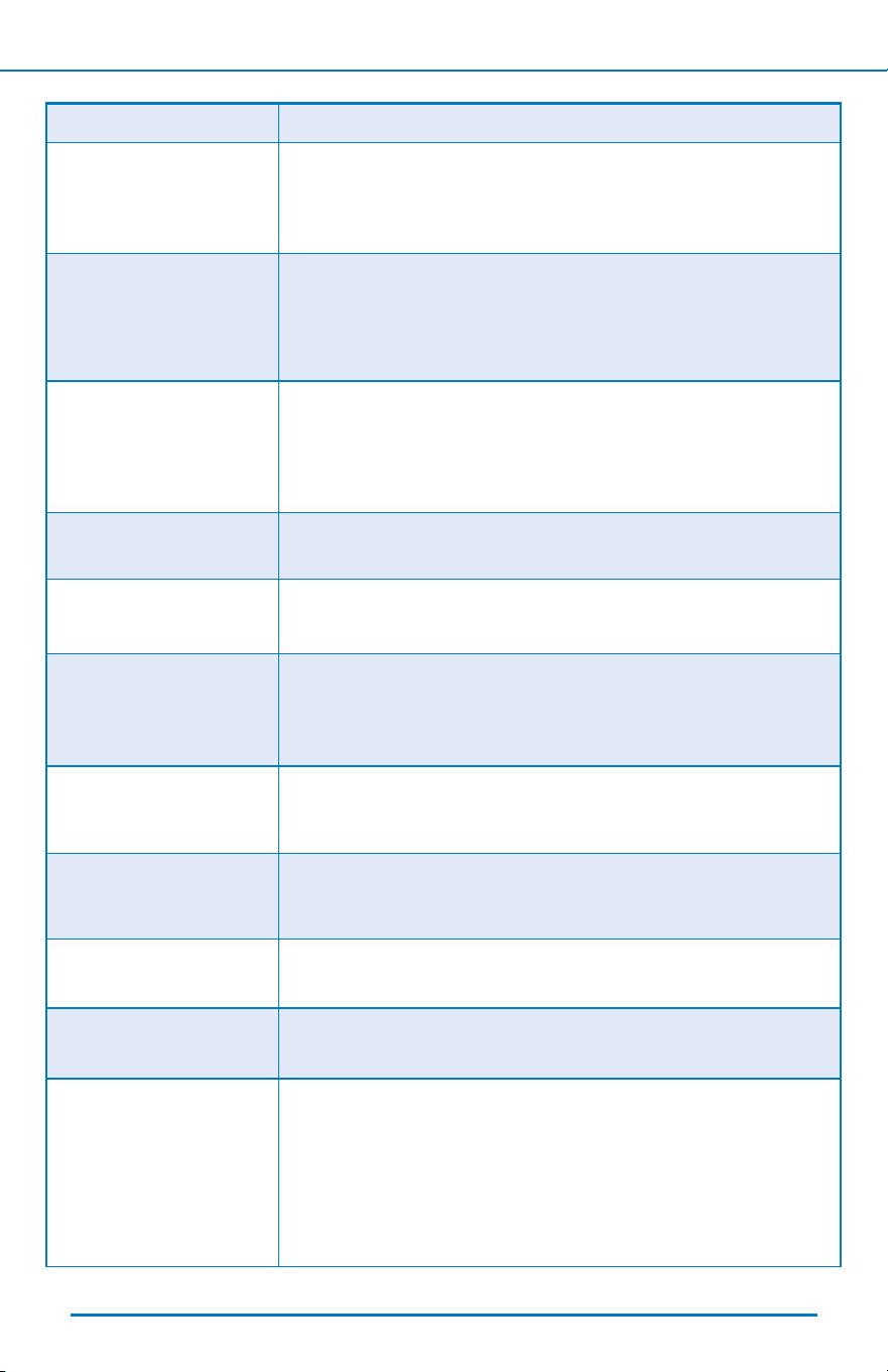
PERFORMANCE DATA SHEET
Data Summary Table
WH-SF40 WH-SF60
Max Compensated Hardness - grains/gal (mg/L) 200 grains/gal (3424 mg/L) 200 grains/gal (3424 mg/L)
Maximum Ferrous Iron Reduction - ppm 1 ppm 1 ppm
Minimum - pH 6.5 min pH 6.5 min pH
8% Cross-Linked Cation Resin - cu ft (L) 1 cu ft (28.3L) 1.5 cu ft (42.5L)
Operating Temp. Range and Ambient Temperature -°F (°C)
40-100°F (4-38°C) 40-100°F (4-38°C)
Mineral Tank Size - in. (cm) 10” I.D. x 35” (25.4 I.D. x 88.9 cm) 12” I.D. x 35” (30.48 I.D. x 88.9 cm)
Service Flow Rate
- gpm 11.02 gpm 11.1 gpm
Pressure Drop at Service Flow Rate - psi 15 psi 15 psi
Maximum Flow Rate to Drain During Regeneration-
Backwash - gpm (L/min)
2.4 gpm (9.1 L/min) 3.5 gpm (13.2 L/min)
Operating Pressure Range - psi (bar) 20-125 psi (1.3-8.6 bar) 20-125 psi (1.3-8.6 bar)
Minimum Water Flow Required - gpm (L/min) 2.4 gpm (9.1 L/min) 3.5 gpm (13.2 L/min)
Frequency of Regeneration Demand Demand
Salt Storage - lb (kg) 230 lbs (104 kg) 230 lbs (104 kg)
Height - in. (cm) 43” (109 cm) 43” (109 cm)
Footprint - in. (cm) 30” x 15” (76 cm x 38 cm) 30” x 15” (76 cm x 38 cm)
Electrical Rating 12 VAC, 60Hz, 650mA 12 VAC, 60Hz, 650mA
Plumbing Connections 1” male (MNPT) 1” male (MNPT)
Approximate Shipping Weight - lbs (kg) 92 lbs (42 kg) 120 lbs (54 kg)
This product is eciency rated according to NSF/ANSI 44. The stated eciencies are valid only at the specied salt dosage
and ow rate.
Model Flow Rate Rated Eciency Salt Dosage Capacity at That Dosage
WH-SF40 11.02 gpm 4,423 grains / lb 3 lbs 13,269 grains
WH-SF60 11.1 gpm 4,543 grains / lb 4.5 lbs 20,443 grains
Aquasana, Inc. 6310 Midway Road · Haltom City, Texas 76117 · 866.662.6885
An Eciency-rated water softener is a Demand-initiated regeneration softener that also complies with specic performance
specications intended to minimize the amount of regenerant brine and water used in its operation. Eciency-rated water soft-
eners shall have a rated salt eciency of no less than 3,350 grains of total hardness exchange per pound of salt (based on NaCl
equivalency) (477 grams of total hardness exchange per kilogram of salt), and shall not deliver more salt than its listed rating.
Eciency is measured by a laboratory test described in NSF/ANSI 44.
The test represents the maximum possible eciency that the system can achieve. Operational eciency is the actual eciency
achieved after the system has been installed. It is typically less than the eciency due to individual application factors including
water hardness, water usage, and other contaminants that reduce the softener’s capacity.
Conforms to NSF/ANSI 44 for the specic performance claims below as veried and substantiated by test data.
Certied by IAPMO R&T against NSF/ANSI 44 for water hardness,
NSF/ANSI/CAN 372 and CSA B483.1.
18
• Use only clean salt intended for water softener use, such as crystal, pellet, nugget, or button. Do not use natural rock salt.
Do not mix salt types.
• Softener is not intended to be used for treating water that is microbiologically unsafe or of unknown quality without
adequate disinfection before or after the system.
< Back To Table of Contents Next >
This warranty does not include Rhino® Filters. See full warranty information for the Rhino® Filters in the original Rhino® manual.
This warranty does not include the UV Filter. See full warranty information for the UV Filter in the original UV manual.
SimplySoft
®
Water Softener Warranty Coverage
Component Limited Warranty Duration
Control Valve 5 years
Pressure Vessel and Brine Tank 10 years
Installation Kit, Pre- & Post-Filter Housings
(if included with original purchase)
12 months
WHO IS COVERED
AQUASANA AND ITS SUPPLIERS, (herein collectively referred to as
“Manufacturer”) warrants to the owner of the home where the water
softener is initially installed (hereinafter “Owner”). The warranty is
restricted to the water softener used in a single-family residence in
the United States of America and is void if moved from the original
installation location. If you purchased from an Aquasana-authorized
reseller or dealer, proof of purchase is required.
WHAT IS COVERED
This Warranty covers defects in materials or workmanship on the
control valve (except for Wear and Tear items – Media, Piston,
Seals and Brine Valve), pressure tank, and brine tank during
the limited warranty period of your SimplySoft
®
Water Softener
System only as dened below. Any additional products purchased
with the original system or separately (may or not include pre-
or post-lters, Rhino Whole House Filters, or other products or
ttings) are warranted according to the information provided in
their documentation. The warranty is only valid when the water
softener is installed, operated, and maintained in accordance
with the instructions accompanying the product and found on
Aquasana.com and not subject to freezing or vacuum. A water
softener should be installed in such a manner that, if the tank or
any connection thereto should leak, the resulting ow of water
will not cause damage to the area in which it is installed. For
detailed instructions read the manual accompanying the water
softener and review drawings in the manual.
FOR HOW LONG
The warranty runs for the length of time specied in the chart below
from the date of purchase by a consumer (hereinafter “Warranty
Period”). No warranty coverage will be provided if the claimant is
unable to provide proof of purchase. Water conditions and use rates
may limit the functional lifespan of your water softener or impact
the life of the aforementioned “Wear and Tear” items.
WHAT AQUASANA WILL DO
1. If necessary, the Manufacturer will provide a replacement
component that fullls the remaining estimated life of
your original purchase and send it to you with installation
instructions. If industry standards, product improvements
or product obsolescence prohibit Manufacturer from
furnishing an identical model replacement water softener
under this warranty, the Owner will be furnished with a new
water softener of comparable capacity and functionality;
however, the Owner will be charged for the additional value
of the item(s) which Manufacturer has incorporated in the
replacement water softener.
2. Components – If a component of the control valve, the
pressure tank or the brine tank proves to Manufacturer’s
satisfaction to be defective in material or workmanship within
the warranty period listed, the Manufacturer will furnish the
Owner with a replacement for the defective part(s).
3. Return of Defective Water Softener and Component Parts –
Manufacturer reserves the right to examine the alleged defect in
the water softener or component part(s), and it will be the Owner’s
obligation to return the water softener and/or component part(s)
to the Manufacturer at the Manufacturers request.
a. When returning a complete water softener, it must
include all component parts.
b. When returning component part(s), they must be
individually tagged and identied with the water softener’s
model number, date of purchase, and date of installation.
WHAT IS NOT COVERED
1. This Warranty applies only to products purchased from
authorized Aquasana resellers.
2. This warranty does not cover lters cartridges, auxiliary equipment,
and any systems that were not installed in compliance with the
instructions or that have been abused or operated incorrectly. This
Warranty applies only to products purchased from Aquasana or an
Aquasana-authorized reseller or dealer.
3. The Limited Warranty stated herein is in lieu of any and all
warranties, express or implied (whether written or oral),
including, but not limited to, the implied warranties of
merchantability and tness for a particular purpose.
4. Manufacturer shall not be liable for any incidental,
consequential, special, or contingent damages or expenses,
arising, directly or indirectly, from any defect in the water
softener or the use of the water softener.
5. Manufacturer shall not be liable for any water damage
arising, directly or indirectly, from any defect in the water
softener or component part(s) or from its use.
6. Manufacturer shall not be liable for any damage or product
failures caused by any of the following:
• The water softener or any of its component parts have
been subject to misuse, alteration, neglect or accident.
• The water softener has not been installed in accordance
with the applicable local plumbing and/or building code(s)
and/ or regulations or in their absence.
• The water softener is not installed, operated and
maintained in accordance with the printed Manufacturer’s
instructions, including if the water softener has any
additional aftermarket equipment introduced into the
system not approved by the manufacturer.
• The water softener is exposed to highly corrosive conditions.
• The water softener is not continuously supplied with
potable water.
• The water softener is not operated within the factory
calibrated temperature and pressure limits.
• The water softener is moved from its original installation
location.
• The water softener is installed in direct sunlight or exposed
to freezing temperatures.
• The water softener or any of its component parts fail due
to iron or sediment build-up or chlorine degradation.
• Clogging due to purchaser’s failure to replace the pre-lter
cartridge if sold as part of the original system.
• Damage caused by re, ood or acts of God.
• Damage caused by over-pressurization in the water line.
7. This warranty does not cover damage caused by the use of parts
that are not genuine Aquasana parts. This includes, but is not
limited to replacement lters, faucets, and/or diverter valves.
8. Except when specically prohibited by the applicable state
law, the Owner, and not the Manufacturer, shall be liable
for and shall pay for all charges for labor or other expenses
incurred in the removal, repair or replacement of the water
lter or any component part(s) claimed to be defective or any
expense incurred to remedy any defect in the product. Such
charges may include, but are not necessarily limited to:
a. All freight, shipping, handling and delivery costs of forwarding
a new water softener or replacement part(s) to the owner.
b. All costs necessary or incidental in removing the defective
water softener or component part(s) and installing a new
water softener or component part(s)
c. Any material required to complete, and/or permits required
for, installation of a new water softener or replacement
part(s), and
All costs necessary or incidental in returning the water softener or
component part(s) to a location designated by the manufacturer.
HOW TO GET SERVICE
To receive service under this Warranty, you must contact
Aquasana (A. O. Smith Water Treatment (North America),
Inc.) at 1-866-662-6885 or [email protected] within the
Warranty Period to describe the problem to a customer service
representative who will verify that the product is under warranty
and determine whether a part or the system will be replaced
and whether you must send back the unit. You will be required
to provide both proof of purchase and proper installation.
SimplySoft
®
40,000 & 60,000 Grain
Water Softener 5/10 Year Limited Warranty
< Back To Table of Contents Next >
19
Protect your investment and save money with Water for Life
®
.
Our Water for Life
®
program helps you protect the investment you’ve made in
your family’s health with an extended limited warranty on your new ltration
system, a 15% discount on replacement lters, and free shipping.
*Exclusionsapply.LimitedWarrantydetailsareavailableataquasana.com.BenetsareforthetermofWaterforLifemembership.
Free Shipping
Replacements shipped to
you right when you need
them – at no extra cost.
Discounted
Replacements
The only way to lock
in a 15% discount on
replacement lters.
Extended
Limited Warranty
Our performance promise
to you – free replacement
parts when needed.
*
No Contract
Free to join and cancel
anytime – no long-term
commitment required.
CONTACT US TO LEARN MORE
866-275-2319
< Back To Table of Contents
20