GB
1.1PLEASEREADBEFOREUSINGTHISMANUAL
•Thismanualispartoftheproductandshouldbekeptneartheinstrumentforeasyand
quickreference.
•Theinstrumentshallnotbeusedforpurposesdifferentfromthosedescribedhereunder.
Itcannotbeusedasasafetydevice.
•Checktheapplicationlimitsbeforeproceeding.
•Copelandreservestherighttochangethecompositionofitsproducts,evenwithout
notice,ensuringthesameandunchangedfunctionality.
1.2SAFETYPRECAUTIONS
•Checkthesupplyvoltageiscorrectbeforeconnectingtheinstrument.
• Donotexposetowaterormoisture:usethecontrolleronlywithintheoperatinglimits
avoidingsuddentemperaturechangeswithhighatmospherichumiditytopreventformation
ofcondensation.
•Warning:disconnectallelectricalconnectionsbeforeanykindofmaintenance.
•FittheprobewhereitisnotaccessiblebytheEndUser.Theinstrumentmustnotbeopened.
•Incaseoffailureorfaultyoperationsendtheinstrumentbacktothedistributororto
Copeland (See address) with a detailed description of the fault.
•Considerthemaximumcurrentwhichcanbeappliedtoeachrelay(seeTechnicalData).
•Ensurethatthewiresforprobes,loadsandthepowersupplyareseparatedandfarenough
fromeachother,withoutcrossingorintertwining.
•Incaseofapplicationsinindustrialenvironments,theuseofmainsfilters(ourmod.FT1)in
parallelwithinductiveloadscouldbeuseful.
1.3DISPOSALOFTHEPRODUCT
Theappliance(ortheproduct)mustbedisposedofseparatelyinaccordancewith
thelocalwastedisposallegislationinforce.
OPERATINGMANUAL
Comp
8A/230Vac
or
16A/230Vac
9
Line
8
Power
Supply
DigInput
4
HOTKEY
1 2 3
Room
1 2 3
n.c.
Comp
Line
9
Power
Supply
8
8A/230Vac
10
11 12
Line
AUX
n.c.
Comp
Def
Line
Room
Evap
4
9
Power
Supply
1 2 3
8
8A/230Vac
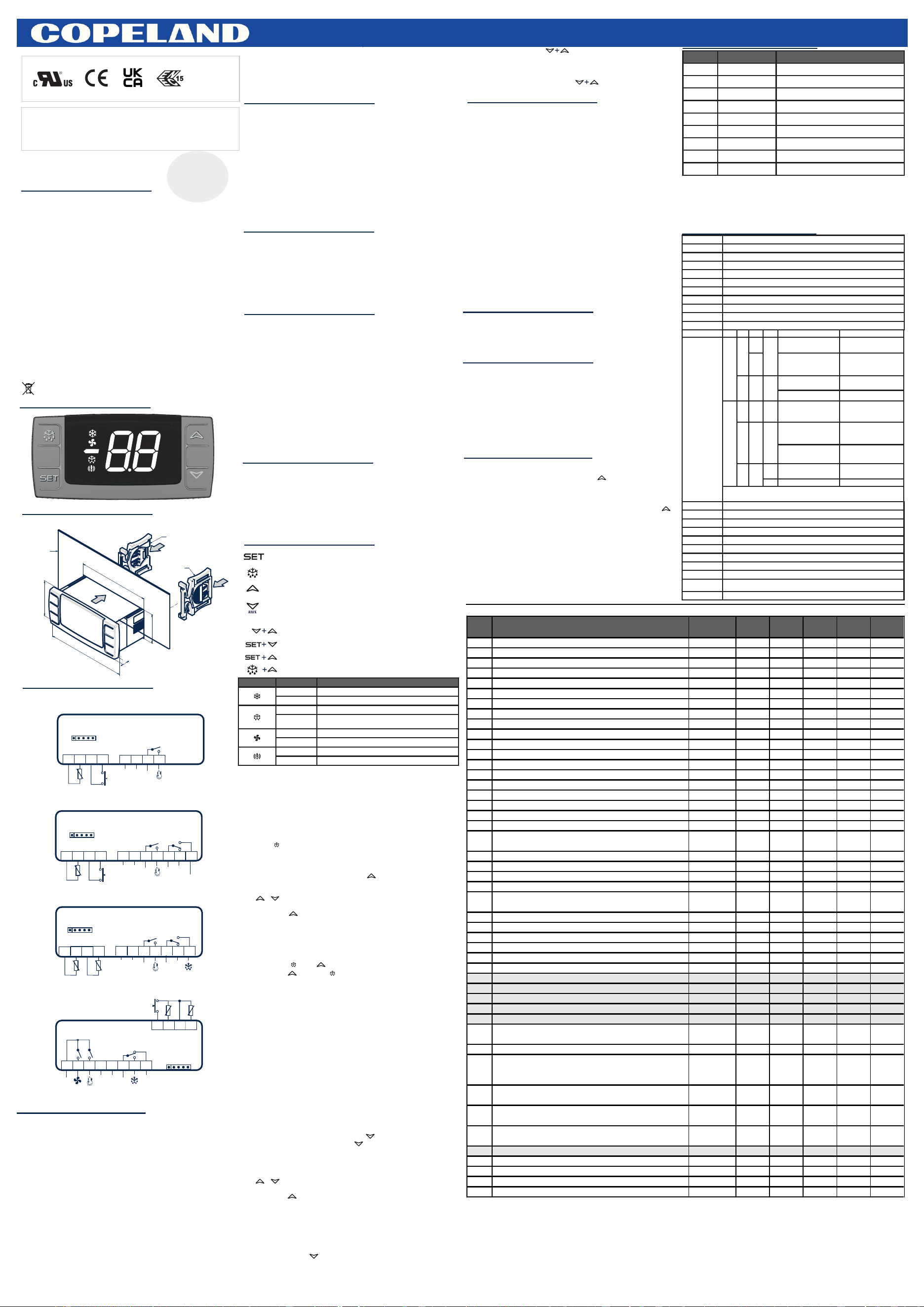
5.GENERALDESCRIPTION
The XR06CX, format 32x74x60 mm, is microprocessor based controller, suitable for
applicationsonmediumorlowtemperatureventilatedrefrigeratingunits.Ithasthreerelay
outputstocontrolcompressor,fan,anddefrost,whichcanbeeitherelectricalorreversecycle
(hotgas).Itisalsoprovidedwith2NTCprobeinputs,thefirstonefortemperaturecontrol,the
secondone,tobelocatedontotheevaporator,tocontrolthedefrostterminationtemperature
andtomanagedthefanandit'sprovidedwithaconfigurabledigitalinput.WiththeHOTKEY
it'spossibletoprogramtheinstrumentinaquickandeasyway.
6.2COOLINGAPPLICATIONS
Theregulationisperformedaccordingtothetemperaturemeasuredbyprobe.Theinstrument
isprovidedwiththeCHprogrammableparameterwichenablestheusertosettheregulation
bothforheatingorcoolingapplications:
•CH=cL‑‑>coolingapplications;
•CH=Ht‑‑>heatingapplications.
Theregulationisperformedaccordingtothetemperaturemeasuredbythethermostatprobe
withapositivedifferentialfromthesetpoint:ifthetemperatureincreasesandreachessetpoint
plusdifferentialthecompressorisstartedandthenturnedoffwhenthetemperaturereaches
thesetpointvalueagain.
6.3HEATINGAPPLICATIONS(OnlyXR01CX)
TheHyvalueisautomaticallysubtractedtotheSETPOINT.Ifthetemperaturedecreasesand
reaches set point minus differential the output is started and then turned off when the
temperaturereachessetpointvalueagain.
XR02CX‑XR03CX:Defrostisperformedthroughasimplestopofthecompressor.Parameter
idcontrolstheintervalbetweendefrostcycles,whileitslengthiscontrolledbyparameterMd.
XR04CX‑XR06CX:Twodefrostmodesareavailablethroughthetdparameter:
• td=ELdefrostthroughelectricalheater(compressorOFF);
•td=inhotgasdefrost(compressorON).
Otherparametersareusedtocontroltheintervalbetweendefrostcycles(id),itsmaximum
length(Md)andtwodefrostmodes:timedorcontrolledbytheevaporator'sprobe.Attheendof
defrostdrippingtimeisstarted,itslengthissetinthedtparameter.Withdt=0thedrippingtime
isdisabled.
The free voltage digital input is programmable in different configurations by the iF
parameter.
11.1DOORSWITCH(iF=do)
11.2EXTERNALALARM(iF=EA)
Assoonasthedigitalinputisactivatedtheunitwillwaitforditimedelaybeforesignalling
theEAalarmmessage.Theoutputsstatusdon'tchange.Thealarmstopsjustafterthe
digitalinputisde‑activated.
11.3SERIOUSALARM(iF=bA)
Whenthedigitalinputisactivated,theunitwillwaitfordidelaybeforesignallingtheCA
alarmmessage.TherelayoutputsareswitchedOFF.Thealarmwillstopassoonasthe
digitalinputisde‑activated.
11.5STARTDEFROST(iF=dF)
Itstartsadefrostiftherearetherightconditions.Afterthedefrostisfinished,thenormal
regulationwillrestartonlyifthedigitalinputisdisabledotherwisetheinstrumentwillwait
untiltheMdsafetytimeisexpired.
11.6INVERSIONOFTHEKINDOFACTION:HEATING‑COOLING(iF=Hc)
Thisfunctionallowstoinverttheregulationofthecontroller:fromcoolingtoheatingand
viceversa.
Theinstrumentsareprovidedwithscrewterminalblocktoconnectcableswithacross
2
sectionupto2,5mm .Beforeconnectingcablesmakesurethepowersupplycomplieswith
theinstrument'srequirements.Separatetheprobecablesfromthepowersupplycables,
fromtheoutputsandthepowerconnections.Donotexceedthemaximumcurrentallowed
oneachrelay,incaseofheavierloadsuseasuitableexternalrelay.
13.1PROBES
Theprobesshallbemountedwiththebulbupwardstopreventdamagesduetocasual
liquidinfiltration.Itisrecommendedtoplacethethermostatprobeawayfromairstreamsto
correctlymeasuretheaverage roomtemperature.Placethedefrost terminationprobe
amongtheevaporatorfinsinthecoldestplace,wheremosticeisformed,farfromheaters
orfromthewarmestplaceduringdefrost,topreventprematuredefrosttermination.
WithFCparameteritcanbeselectedthefansfunctioning:
•FC=cnwillswitchONandOFFwiththecompressorandnotrunduringdefrost
•FC=onfanswillrunevenifthecompressorisoff,andnotrunduringdefrost
After defrost, there is a timed fan delay allowing for drip time, set by means of the Fd
parameter.
•FC=cyfanswillswitchONandOFFwiththecompressorandrunduringdefrost
•FC=oYfanswillruncontinuouslyalsoduringdefrost.
AnadditionalparameterFSprovidesthesettingoftemperature,detectedbytheevaporator
probe,abovewhichthefansarealwaysOFF.Thisisusedtomakesurecirculationofaironlyif
histemperatureislowerthansetinFS.
Instrumentsshallbemountedonverticalpanel,ina29x71mmhole,andfixedusingthe
specialbracketsupplied.
Thetemperaturerangeallowedforcorrectoperationis0÷60°C.Avoidplacessubjectto
strongvibrations,corrosivegases,excessivedirtorhumidity.Thesamerecommendations
applytoprobes.Letaircirculatebythecoolingholes.
10.1HOWTOSEETHESETPOINT
1.PushandimmediatelyreleasetheSETkey,thesetpointwillbeshowed;
2.PushandimmediatelyreleasetheSETkeyorwaitabout5storeturntonormalvisualisation.
10.2HOWTOCHANGETHESETPOINT
1.PushtheSETkeyformorethan2secondstochangetheSetpointvalue;
2.Thevalueofthesetpointwillbedisplayedandstartsblinking;
3.TochangetheSETvaluepushtheoornarrowswithin10s;
4.TomemorisethenewsetpointvaluepushtheSETkeyagainorwait15s.
10.3HOWTOSTARTAMANUALDEFROST
10.4HOWTOCHANGEAPARAMETERVALUE
Tochangetheparameter'svalueoperateasfollows:
1.EntertheProgrammingmodebypressingtheSET+ keysfor3s;
2.Selecttherequiredparameter.
3.PresstheSETkeytodisplayitsvalue(setvaluestartstoblink);
4.Use or tochangeitsvalue;
5.PressSETtostorethenewvalueandmovetothefollowingparameter.
Toexit:PressSET+ orwait15swithoutpressingakey.
NOTE:thesetvalueisstoredevenwhentheprocedureisexitedbywaitingthetime‑outto
expire.Pleaserestartthecontrollerafterchangetheparameters
10.5HOWTORESETTOTHEFACTORYPARAMETERVALUE(Option)
Inthefirst60saftercontrollerpower‑on,itallowsusertoresettothefactoryparameterthrough
keycombinationwithstepsbelow:
1.StartpressingDEF keyand for5s;
2.Thenreleasejust butkeepDEF keyanother5s.Thenparameterresetsuccessfullyby
controllerre‑startautomatically.
NOTE:
•TheParametersFactoryResetfunctionshallbeaccessibleinthefirst60secondsfromthe
devicepower‑on.Thedefaultconfigurationwillinitiatetheloading,duringthistimeallregulation
willbeinterrupted,relayswillbepoweredoff,andthecontrollersisreset.
•It allows user to reset to a customized parameter map through Hotkey,to download the
parametersintothecontrollerfirstly,thenexecutetheabove2steps.
Hereisthesetpstoupdatetocustomizedparaleterintothecontroller.
1.SaveyourownparametermapintoaHotkey
2.Plug‑inthehotkeyintothecontroller,poweroffthecontroller
3.Thenpoweronthecontroller,theparameterintoHotkeywillbedownloadedintothecontroller
automaticallywithdisplayshowing'En'label.
NOTE:Afterresetto user parameter,it will be impossible to reset toEmersonparameter
anymore.
10.7TOLOCKTHEKEYBOARD
Keeppressedformorethan3sthe keys.
ThePFmessagewillbedisplayedandthekeyboardwillbelocked.Ifakeyispressedmore
than3sthePFmessagewillbedisplayed.
10.8TOUNLOCKTHEKEYBOARD
Keeppressedtogetherformorethan3sthe keystillthePnmessagewillbe
displayed.
PushtheDEF keyformorethan2secondsandamanualdefrostwillstart,thepre‑conditionis
evaporatorprobetemplowerthandE.
14.2HOWTOPROGRAMANINSTRUMENTUSINGHOTKEY(DOWNLOAD)
Probe alarms P1 and P2 start some seconds after the fault in the related probe; they
automaticallystopsomesecondsaftertheproberestartsnormaloperation.Checkconnections
beforereplacingtheprobe.TemperaturealarmsHAandLAautomaticallystopassoonasthe
temperaturereturnstonormalvalues.
AlarmsEAandCA(withiF=bL)recoverassoonasthedigitalinputisdisabled.
15.1ALARMRECOVERY
6.1THEREGULATIONOUTPUT(OnlyforXR01CX)
11.4SWITCHINGSECONDRELAYON(iF=Au)(OnlyXR03CX)
Wheno1=Auitswitchesonandoffthesecondrelay.
XR04CX8Aor16ACOMP.
XR03CX8Aor16ACOMP.
XR01CX‑XR02CX8Aor16ACOMP.
It signals the door status and the corresponding relay output status through the dC
parameter:no=normal(anychange);Fn=FanOFF;CP=CompressorOFF;FC=
CompressorandfanOFF.
Sincethedoorisopened,afterthedelaytimesetthroughparameterdi,thedooralarmis
enabled,thedisplayshowsthemessagedAandtheregulationrestartsifrd=y.The
alarmstopsassoonastheexternaldigitalinputisdisabledagain.Withthedooropen,the
highandlowtemperaturealarmsaredisabled.
1.TurnOFFtheinstrument;
2.InsertaprogrammedHotKeyintothe5PINreceptacleandthenturntheController
ON;
3.Automatically the parameter list of the Hot Key is downloaded into the Controller
memory,successfullyfollowedbyappearEnlabel;
4.After10secondstheinstrumentwillrestartworkingwiththenewparameters;
5.RemovetheHotKey.
NOTE:theErmessageisdisplayedforfailedprogramming.ChecktheHotkeyconnection,
checkthedataintoHotkeyandrepeattheactionsabove..
8.1FANSANDDIGITALINPUT
When the digital input is configured as door switch iF=do, fans and compressor status
dependsonthedCparametervalue:
dC=nonormalregulation;
dC=FnfansOFF;
dC=cPcompressorOFF;
dC=FccompressorandfansOFF.
Whenrd=y,theregulationrestartwithdooropenalarm.
XR01CXDIGITALTHERMOSTAT
XR02CXDIGITALCONTROLLERWITH“OFFCYCLE”DEFROST
XR03CXDIGITALCONTROLLERWITHAUXILIARYRELAY
XR04CXDIGITALCONTROLLERWITHDEFROSTRELAY
XR06CXDIGITALCONTROLLERWITHDEFROSTANDFANSMANAGEMENT
3.DIMENSIONSANDCUTOUT
4.C ON NE CTIONS
1.GENERALWARNINGS
2.FRONTPANEL
6.REGULATION
8.FANS(OnlyXR06CX)
7.DEFROST
11.DIGITALINPUTS
13.ELECTRICALCONNECTIONS
12.INSTALLATIONANDMOUNTING
DEFAULTSETTINGVALUES
15.ALARMSIGNALLING
16.TECHNICALDATA
8A/230Vac
or
16A/230Vac
4
HOTKEY
DigInput
Room
HOTKEY
8A/230Vac
or
16A/230Vac
Line
11
12
10
6
7
6
7
6
7
71
78,5
29
36,9
BRACKET
BRACKET
PANEL
6
DigInput
HOTKEY
Room
Evap
4 5 6 7 8
n.c.
Power
Supply
1 2 3
Comp
Def
9
Fan
Max
16A
16A/230Vac
4A/230Vac
Line
8A/230Vac
Line
10
11
12
1599020280Rel.1.0
XR06CX16ACOMP.
*
*
XR01CX‑XR02CX‑XR03CX‑XR04CX‑XR06CX
Todisplaytargetsetpoint,inprogrammingmodeitselectsaparameterorconfirman
operation
Tostartamanualdefrost
Inprogrammingmodeitbrowsestheparametercodesorincreasesthedisplayed
value
Inprogrammingmodeitbrowsestheparametercodesordecreasesthedisplayed
value
KEYSCOMBINATION
Tolockorunlockthekeyboard
Toenterinprogrammingmode
Toreturntoroomtemperaturedisplay
10.FRONTPANELCOMMANDS
Toresetparameters
10.6HIDDENMENU
9.VOLTAGEPROTECTION(Option)
TheHLVDfunctionprovidesanalarmifthevoltageofthepowersupplyoutofthenormalrange
vUandvL.
Parametersvcenablethisfunction.vUandvLdefinethelimitationthresholdofthepower,and
ifthevoltageoutoftherange,thealarmwillbetriggered.Thenthesystemwillgotothe
dedicateactionaccordingtotheparametervr.
•vr=ntheregulationnotstop
•vr=ytheregulationstop
Whenthepowerbacktothenormalrange,thenalarmdisappeared,thesystemwillstarttorun
thenormalregulation.
Thehiddenmenuincludesalltheparametersoftheinstrument.
HOWTOENTERTHEHIDDENMENU
1.EntertheProgrammingmodebypressingtheSET+ keysfor3s(Setvaluestartsblinking);
2.Releasedthekeys,thenpushagaintheSET+ keysformorethan7s.TheL2labelwillbe
displayedimmediatelyfollowedfromtheHyparameter.
NOWYOUAREINTHEHIDDENMENU.
3.Selecttherequiredparameter;
4.PresstheSETkeytodisplayitsvalue;
5.Use or tochangeitsvalue;
6.PressSETtostorethenewvalueandmovetothefollowingparameter.
Toexit:PressSET+ orwait15swithoutpressingakey.
NOTE1:ifnoneparameterispresentinL1,after3sthenPmessageisdisplayed.Keepthekeys
pushedtilltheL2messageisdisplayed.
NOTE2:thesetvalueisstoredevenwhentheprocedureisexitedbywaitingthetime‑outto
expire.
HOWTOMOVEAPARAMETERFROMTHEHIDDENMENUTOTHEFIRSTLEVELAND
VICEVERSA.
EachparameterpresentintheHIDDENMENUcanberemovedorputinto“THEFIRSTLEVEL”
(userlevel)bypressingSET+ .InHIDDENMENUwhenaparameterispresentinFirstLevel
thedecimalpointison.
1.Programonecontrollerwiththefrontkeypad;
2.WhenthecontrollerisON,inserttheHotkeyandpush key;theuPmessageappears
followedabyflashingEn;
3.PushSETkeyandtheEnwillstopflashing;
4.TurnOFFtheinstrumentremovetheHotKey,thenturnitONagain.
NOTE:theErmessageisdisplayedforfailedprogramming.Inthiscasepushagain
keyifyouwanttorestarttheuploadagainorremovetheHotkeytoaborttheoperation.
14.1HOWTOPROGRAMTHEHOTKEYFROMTHEINSTRUMENT(UPLOAD)
14.HOWTOUSETHEHOTKEY
ModelXR01CX,in32x74x50mmshortformat,isasinglestagetemperaturethermostat
suitableforapplicationsinthefieldofrefrigerationorheating.Itprovidesarelayoutputtodrive
the compressor. It is also provided with 1 NTC probe input and one digital input. The
instrumentisfullyconfigurablethroughspecialparametersthatcanbeeasilyprogrammed
throughthekeyboardorbytheHOTKEY.
ModelXR02CX,in32x74x50mmshortformat,isadigitalcontrollerwithoffcycledefrost
designedforrefrigerationapplicationsatnormaltemperature.Itprovidesarelayoutputto
drivethecompressor.Itisalsoprovidedwith1NTCprobeinputandonethedigitalinput.The
instrumentisfullyconfigurablethroughspecialparametersthatcanbeeasilyprogrammed
throughthekeyboardorbytheHOTKEY.
TheXR03CX,in32x74x50mmshortformat,ismicroprocessorbasedcontrollersuitablefor
applicationsonnormaltemperaturerefrigeratingunits.Itprovidestworelayoutput:onefor
compressorandtheotheroneforalarmsignallingorasauxiliaryoutput.ItprovidesanNTC
probeinputandadigitalinputforalarmsignalling,forswitchingtheauxiliaryoutputorforstart
defrost.Theinstrumentisfullyconfigurablethroughspecialparametersthatcanbeeasily
programmedthroughthekeyboardorthebyHOTKEY.
TheXR04CX,in32x74x50mmshortformat,ismicroprocessorbasedcontrollersuitablefor
applicationsonnormalorlowtemperaturerefrigeratingunits.Itprovidestworelayoutput:one
forcompressorandtheotheronefordefrost.ItprovidestwoNTCprobeinputs,oneforroom
temperatureandotheronetocontroldefrosttermination.Theinstrumentisfullyconfigurable
throughspecialparametersthatcanbeeasilyprogrammedthroughthekeyboardorbythe
HOTKEY.
LABEL DESCRIPTION RANGE XR01CX XR02CX XR03CX XR04CX XR06CX
Set SetPoint LS‑US 5.0 3.0 3.0 ‑5.0 ‑5.0
Hy Differential 0.1÷25°C/1÷45°F 2.0°C/4°F 2.0°C/4°F 2.0°C/4°F 2.0°C/4°F 2.0°C/4°F
LS MinimumSetPoint ‑55°C÷SET/‑67°F÷SET ‑55°C/‑55°F ‑55°C/‑55°F ‑55°C/‑55°F ‑55°C/‑55°F ‑55°C/‑55°F
US MaximumSetPoint SET÷99°C/SET÷99°F 99°C/99°F 99°C/99°F 99°C/99°F 99°C/99°F 99°C/99°F
od Outputsactivationdelayatstartup 0÷99min 0 0 0 0 0
AC Anti‑shortcycledelay 0÷50min 1 1 1 1 1
Cy CompressorONtimefaultyprobe.Cy=0comp.alwaysOFF 0÷99min 15 15 15 15 15
Cn CompressorOFFtimefaultyprobe.Cn=0comp.alwaysactive 0÷99min 30 30 30 30 30
CH Kindofaction cL÷Ht cL cL cL _ _
CF Measurementunits:°C=Celsius;°F=Fahrenheit °C‑°F °C/°F °C/°F °C/°F °C/°F °C/°F
rE Resolution(onlyfor°C):dE=decimalbetween‑9.9and9.9°C;in=integer dE–in dE/in dE/in dE/in dE/in dE/in
Ld DefaultDisplay:P1=roomprobe;P2=evaporatorprobe P1‑P2 _ _ _ P1 P1
dy Displaydelay 0÷15min 0 0 0 0 0
ot Firstprobecalibration ‑9.9÷9.9°C/‑17÷17°F 0 0 0 0 0
P2 Secondprobepresence:n=notpresent;y=present n–Y _ _ _ y y
oE Secondprobecalibration ‑9.9÷9.9°C/‑17÷17°F _ _ _ 0 0
td Defrosttype:EL=electricalheater,compressorOFF;in=hotgas,compressorON; EL–in _ _ _ EL EL
dE Defrostterminationtemperature ‑55÷50°C/‑67÷99°F _ _ _ 8.0°C/46°F 8.0°C/46°F
id Intervalbetweendefrostcycles 0÷99hours _ 8 8 6 6
Md
Maximumlengthfordefrost.whenP2=n,(notevaporatorprobe:timeddefrost)itsetsthedefrostduration,whenP2=
y(defrostendbasedontemperature)itsetsthemaximumlengthfordefrost.
0÷99min. _ 20 20 30 30
dd Startdefrostdelay 0÷99min. _ _ _ 0 0
dF Displayduringdefrost:rt=realtemperature;it=startdefrosttemperature;SP=SET‑POINT;dE=labeldF. rt–it–SP–dE _ it it it it
dt Driptime 0÷99min _ _ _ 0 0
dP Defrostatpower‑on:y=atpowerondefroststarts;n=defrostdoesn’tstartatpower‑on y‑n _ _ _ n n
FC
Fans operating mode: cn= in runs with the compressor, OFF during defrost; on= continuous mode, OFF during
defrost;cY=runswiththecompressor,ONduringdefrost;oY=continuousmode,ONduringdefrost.
cn–on–cY–oY _ _ _ _ on
Fd Fansdelayafterdefrost 0÷99min _ _ _ _ 10
FS Fansstoptemperature ‑55÷50°C/‑67÷99°F _ _ _ _ 2.0°C/36°F
AU Maximumtemperaturealarm AL÷99°C/AL÷99°F 99°C/99°F 99°C/99°F 99°C/99°F 99°C/99°F 99°C/99°F
AL Minimumtemperaturealarm ‑55°C÷AU/‑67°F÷AU ‑55°C/‑55°F ‑55°C/‑55°F ‑55°C/‑55°F ‑55°C/‑55°F ‑55°C/‑55°F
Ad Temperaturealarmdelay 0÷99min 15 15 15 15 15
dA Exclusionoftemperaturealarmatstartup 0÷99min 90 90 90 90 90
vc Voltagecontrolswitch n‑y n n n n n
vU Voltageupperthreshold 18÷28V/9÷14V 25/14 25/14 25/14 25/14 25/14
vL Voltagelowerthreshold 18÷28V/9÷14V 19/9 19/9 19/9 19/9 19/9
vr Voltageregulationdisabling n‑y n n n n n
vd VoltageDifferential 0÷25V 5 5 5 5 5
o2
The second relay configuration: nu= not use; CP= compressor; dF=defrost; Fn=fan; AL= alarm; LG= Light;
AU=auxiliary
nu‑CP‑dF‑Fn‑AL‑LG‑
AU
_ _ AU _ _
iP Digitalinputpolarity:oP=activatedbyclosingthecontact;cL=activatedbyopeningthecontact cL–oP cL cL cL _ cL
iF
Digital input configuration: (do/EA/bA/dF/Fn/Hc/Au) do= door switch function; EA= external alarm: “ EA” message is
displayed; bA= serious alarm “CA” message is displayed; dF= defrost activation; Fn=start the evaporator fan;Hc=
inversionofthekindofaction;Au=notused.
do–EA–bA–dF–Fn–Hc
–Au
EA EA do _ do
di
Digital input delay: with iF=EA or bA delay between the detection of the external alarm condition and its signalling.
WithiF=doitrepresentsthedelaytoactivatethedooropenalarm.
0÷99min 5 5 15 _ 15
dC
Compressor and fan status when open door: no= normal; Fn = Fans OFF; cP =Compressor OFF; Fc =
CompressorandfansOFF;
no/Fn/cP/Fc no no no _ FC
rd
Regulation with door open: n = no regulation if door is opened; Y= when di is elapsed regulation restarts even if
dooropenalarmispresent;
n‑y y y y _ y
Fr Parameterfactoryreset y‑n n n n n n
d1 Thermostatprobedisplay ReadOnly ‑‑‑ ‑‑‑ ‑‑‑ ‑‑‑ ‑‑‑
d2 Evaporatorprobedisplay ReadOnly ‑‑‑ ‑‑‑ ‑‑‑ ‑‑‑ ‑‑‑
Pt Parametercodetable ReadOnly ‑‑‑ ‑‑‑ ‑‑‑ ‑‑‑ ‑‑‑
rL Firmwarerelease ReadOnly ‑‑‑ ‑‑‑ ‑‑‑ ‑‑‑ ‑‑‑
显示字符
报警原因
输出状态
P1
Roomprobefailure
Compressoroutputaccordingto“Cy”and“Cn”
P2
Evaporatorprobefailure
Defrostendistimed
HA
Maximumtemperature
Outputsunchanged
LA
Minimumtemperature
Outputsunchanged
EA
Externalalarm
Outputsunchanged
CA
Seriousexternalalarm
AlloutputsOFF
dA
DoorOpen
Compressorandfansrestarts
Hu
Highvoltageofpower
Alloutputsoffexceptalarm/light
Lu
Lowvoltageofpower
Alloutputsoffexceptalarm/light
PurposeofControl
OperatingControl
ConstructionofControl
IncorporatedcontrolintendedtobeusedwithinClassIandClassIIequipment
Housing
SelfextinguishingPC
Case
Frontal32×74mm;depth50or60mm
Mounting
Panelmountingina71×29mmpanelcut‑out
Protection
Rear:IP20(EN60529)Frontal:IP65(EN60529),type1enclosure(UL50e)
Connections
Screwterminalblocks2,5mm2wiring
PowerSupply
Accordingtothemodel:12Vac/dc,±10%;230Vac10%,50/60Hz,115Vac10%,50/60Hz
PowerAbsorption
3,5VAmax
Display
2digits,redLED,14,2mmhigh
DigitalInput
Freevoltagecontact
RelayOutputs
Nominal
Terminal
UL
IEC
XR01/02/
03/04CX
oA1*
SPST16A,
230Vac
8,9
Resistive16A,230Vac,100KCycles(NO)
MotorLoad2HP(16FLA/96LRA),230Vac,
100KCycles(NO)
ResistiveorInductive16(8)A,230Vac,100K
Cycles(NO)
SPST8A,
230Vac
Resistive8A(NOonly),230Vac,30KCycles
(NO)
MotorLoad1∕2HP(4.9FLA/29.4LRA),
230Vac,30KCycles(NO)
PilotDutyB300,230Vac,6KCycles(NO)
ResistiveorInductive8(3)A,230Vac,100K
Cycles(NO)
oA2
SPDT8A,
230Vac
10,11,12
MotorLoad1∕2HP(4.9FLA/29.4LRA),
230Vac,30KCycles(NO)PilotDutyB300,
230Vac,6KCycles
ResistiveorInductive8(3)A,230Vac,100K
Cycles(NO)
Resistive8A,230Vac,30KCycles(NC)
ResistiveorInductive8A,230Vac,30KCycles
(CO)
XR06CX
oA1
SPST16A,
230Vac
**1,3
GeneralPurpose16A(Maxload),230Vac,
50KCycles(NO)
MotorLoad1‑1∕2HP(10FLA/60LRA),
230Vac,30KCycles(NO)
PilotDutyA300,6KCycle(NO)
Resistive16A,230Vac,100KCycles(NO)
Resistive16A,230Vac,100KCycles(NO)
MotorLoad(16FLA/96LRA),230Vac,100K
Cycles(NO)
MotorLoad2HP,230Vac,30KCycles(NO)
ResistiveorInductive10(2)A,230Vac,50K
Cycles(NO)
ResistiveorInductive13Aor12(8)A,230Vac,
100KCycles(NO)
oA2
SPDT8A,
230Vac
7
Resistive8A,230Vac,30KCycles(NO)
MotorLoad1∕2HP(4.9FLA/29.4LRA),
230Vac,30KCycles(NO)
ResistiveorInductive8(3)A,230Vac,30K
Cycles(NO)
8
Resistive8A,230Vac,30KCycles(NC)
Resistive8A,230Vac,30KCycles(CO)
oA3
SPST4A,
230Vac
**1,2
Resistive4A,230Vac,30KCycles(NO)
MotorLoad1/8HP(1.9FLA/11.4LRA),
230Vac,30KCycles(NO)
PilotDutyC300,30KCycles(NO)
ResistiveorInductive3(1)Aor4(1)A,230Vac,
50KCycles(NO)
NOTE:
*oA1notbotharefitted
**Terminal1isashared‘LINE’common.MaximumcurrentRatingis16A.Twoloadconditionsshallbeconsidered,either13A(OA1)+3A
(OA3)or12A(OA1)+4A(Oa3).
DataStoring
onthenon‑volatilememory(EEPROM)
TypeofAction
1.B
PollutionDegree
2
SoftwareClass
A
RateImpulsiveVoltage
2500Vfor115Vacand230VacModels500Vfor12Vmodels
OvervoltageCategory
II
OperationTemperature
0÷60°C(IEC/EN60730‑1),‑20÷60°C(UL60730‑1–CAN/CSAE60730‑1)
StorageTemperature
‑20÷60°C(UL60730‑1).
RelativeHumidity
20÷85%(nocondensing).
Measuringand
RegulationRange
NTC‑40÷110°C(‑40÷230°F),resolution0,1°Cor1°Cor1°F(selectable).
Accuracy
(Ambienttemp.25°C):±0,7°C±1digit.
LED
MODE
SIGNIFICATO
On
Compressorenabled
Flashing
‑Compressoractivationdelayactive(during‑Compressorstopformicro‑door
On
Defrostinprogress
Flashing
‑Defrostdelayactive(duringtimedd)
‑Drippinginprogress(duringtimedt)
On
Fansoutputenabled
Flashing
Fansdelayafterdefrost
On
Alarmshappend
Flashing
‑‑‑‑‑‑
aux
RelayOutputs
Nominal
Terminal
UL
IEC
XR01/02/
03/04CX
oA1*
SPST16A,
230Vac
8,9
Resistive16A,230Vac,100KCycles(NO)
MotorLoad2HP(16FLA/96LRA),230Vac,
100KCycles(NO)
ResistiveorInductive16(8)A,230Vac,100K
Cycles(NO)
SPST8A,
230Vac
Resistive8A(NOonly),230Vac,30KCycles
(NO)
MotorLoad1∕2HP(4.9FLA/29.4LRA),
230Vac,30KCycles(NO)
PilotDutyB300,230Vac,6KCycles(NO)
ResistiveorInductive8(3)A,230Vac,100K
Cycles(NO)
oA2
SPDT8A,
230Vac
10,11,12
MotorLoad1∕2HP(4.9FLA/29.4LRA),
230Vac,30KCycles(NO)PilotDutyB300,
230Vac,6KCycles
ResistiveorInductive8(3)A,230Vac,100K
Cycles(NO)
Resistive8A,230Vac,30KCycles(NC)
ResistiveorInductive8A,230Vac,30KCycles
(CO)
XR06CX
oA1
SPST16A,
230Vac
**1,3
GeneralPurpose16A(Maxload),230Vac,
50KCycles(NO)
MotorLoad1‑1∕2HP(10FLA/60LRA),
230Vac,30KCycles(NO)
PilotDutyA300,6KCycle(NO)
Resistive16A,230Vac,100KCycles(NO)
Resistive16A,230Vac,100KCycles(NO)
MotorLoad(16FLA/96LRA),230Vac,100K
Cycles(NO)
MotorLoad2HP,230Vac,30KCycles(NO)
ResistiveorInductive10(2)A,230Vac,50K
Cycles(NO)
ResistiveorInductive13Aor12(8)A,230Vac,
100KCycles(NO)
oA2
SPDT8A,
230Vac
7
Resistive8A,230Vac,30KCycles(NO)
MotorLoad1∕2HP(4.9FLA/29.4LRA),
230Vac,30KCycles(NO)
ResistiveorInductive8(3)A,230Vac,30K
Cycles(NO)
8
Resistive8A,230Vac,30KCycles(NC)
Resistive8A,230Vac,30KCycles(CO)
oA3
SPST4A,
230Vac
**1,2
Resistive4A,230Vac,30KCycles(NO)
MotorLoad1/8HP(1.9FLA/11.4LRA),
230Vac,30KCycles(NO)
PilotDutyC300,30KCycles(NO)
ResistiveorInductive3(1)Aor4(1)A,230Vac,
50KCycles(NO)
NOTE:
*oA1notbotharefitted
**Terminal1isashared‘LINE’common.MaximumcurrentRatingis16A.Twoloadconditionsshallbeconsidered,either13A(OA1)+3A
(OA3)or12A(OA1)+4A(Oa3).
Nominal
Terminal
UL
IEC
RelayOutputs
XR01/02/
03/04CX
oA1*
SPST
16A,
230Vac
8,9
Resistive16A,230Vac,100KCycles(NO)
MotorLoad2HP(16FLA/96LRA),230Vac,
100KCycles(NO)
ResistiveorInductive16(8)A,230Vac,100K
Cycles(NO)
SPST
8A,
230Vac
Resistive8A(NOonly),230Vac,30KCycles
(NO)
MotorLoad1∕2HP(4.9FLA/29.4LRA),
230Vac,30KCycles(NO)
PilotDutyB300,230Vac,6KCycles(NO)
ResistiveorInductive8(3)A,230Vac,100K
Cycles(NO)
oA2
SPST
8A,
230Vac
MotorLoad1∕2HP(4.9FLA/29.4LRA),
230Vac,30KCycles(NO)PilotDutyB300,
230Vac,6KCycles
ResistiveorInductive8(3)A,230Vac,100K
Cycles(NO)
10,11,12
Resistive8A,230Vac,30KCycles(NC)
ResistiveorInductive8A,230Vac,30K
Cycles(CO)
XR06CX
oA3
SPST
4A,
230Vac
**1,2
Resistive4A,230Vac,30KCycles(NO)
MotorLoad1/8HP(1.9FLA/11.4LRA),
230Vac,30KCycles(NO)
PilotDutyC300,30KCycles(NO)
ResistiveorInductive3(1)Aor4(1)A,230Vac,
50KCycles
oA1
SPST
16A,
230Vac
**1,3
GeneralPurpose16A(Maxload),230Vac,
50KCycles(NO)
MotorLoad1‑1∕2HP(10FLA/60LRA),
230Vac,30KCycles(NO)
PilotDutyA300,6KCycle(NO)
Resistive16A,230Vac,100KCycles(NO)
7
Resistive16A,230Vac,100KCycles(NO)
MotorLoad(16FLA/96LRA),230Vac,100K
Cycles(NO)
MotorLoad2HP,230Vac,30KCycles(NO)
ResistiveorInductive10(2)A,230Vac,50K
Cycles(NO)
oA2
SPST
8A,
230Vac
8
Resistive8A,230Vac,30KCycles(NO)
MotorLoad1∕2HP(4.9FLA/29.4LRA),
230Vac,30KCycles(NO)
ResistiveorInductive13Aor12(8)A,230Vac,
100KCycles(NO)
Resistive8A,230Vac,30KCycles(NC)
Resistive8A,230Vac,30KCycles(CO)
Nominal
Terminal
UL
IEC
RelayOutputs
Xr01/
02/
03/04CX
oA1*
SPST
16A,
230Vac
8,9
Resistive16A,230Vac,100KCycles(NO)
MotorLoad2HP(16FLA/96LRA),230Vac,
100KCycles(NO)
ResistiveorInductive16(8)A,230Vac,100K
Cycles(NO)
SPST
8A,
230Vac
Resistive8A(NOonly),230Vac,30KCycles
(NO)
MotorLoad1∕2HP(4.9FLA/29.4LRA),
230Vac,30KCycles(NO)
PilotDutyB300,230Vac,6KCycles(NO)
ResistiveorInductive8(3)A,230Vac,100K
Cycles(NO)
oA2
SPST
8A,
230Vac
10,11,12
MotorLoad1∕2HP(4.9FLA/29.4LRA),
230Vac,30KCycles(NO)PilotDutyB300,
230Vac,6KCycles
ResistiveorInductive8(3)A,230Vac,100K
Cycles(NO)
Resistive8A,230Vac,30KCycles(NC)
ResistiveorInductive8A,230Vac,30K
Cycles(CO)
XR06CX
oA3
SPST
4A,
230Vac
**1,2
Resistive4A,230Vac,30KCycles(NO)
MotorLoad1/8HP(1.9FLA/11.4LRA),
230Vac,30KCycles(NO)
PilotDutyC300,30KCycles(NO)
ResistiveorInductive3(1)Aor4(1)A,230Vac,
50KCycles
oA1
SPST
16A,
230Vac
**1,3
GeneralPurpose16A(Maxload),230Vac,
50KCycles(NO)
MotorLoad1‑1∕2HP(10FLA/60LRA),
230Vac,30KCycles(NO)
PilotDutyA300,6KCycle(NO)
Resistive16A,230Vac,100KCycles(NO)
Resistive16A,230Vac,100KCycles(NO)
MotorLoad(16FLA/96LRA),230Vac,100K
Cycles(NO)
MotorLoad2HP,230Vac,30KCycles(NO)
ResistiveorInductive10(2)A,230Vac,50K
Cycles(NO)
oA2
SPST
8A,
230Vac
7
Resistive8A,230Vac,30KCycles(NO)
MotorLoad1∕2HP(4.9FLA/29.4LRA),
230Vac,30KCycles(NO)
ResistiveorInductive13Aor12(8)A,230Vac,
100KCycles(NO)
8
Resistive8A,230Vac,30KCycles(NC)
Resistive8A,230Vac,30KCycles(CO)
NOTE:*oA1notbotharefitted
**Terminal1isashared‘LINE’common.MaximumcurrentRatingis16A.Twoloadconditionsshallbeconsidered,either13A(OA1)+3A
(OA3)or12A(OA1)+4A(OA3).
XR01CX - XR02CX - XR03CX - XR04CX - XR06CX