USE AND CARE GUIDE
Questions, problems, missing parts?
Before returning to the store, call
9 a.m – 5 p.m., CST, Monday-Friday
1-866-441-5080
Assembly Instructions
Item #211-4782 Model # M48FC
Item #211-4783 Model # M48FCTB
Item #211-4784 Model # M48FCTR
Item #211-4785 Model # M48FCW
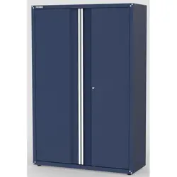
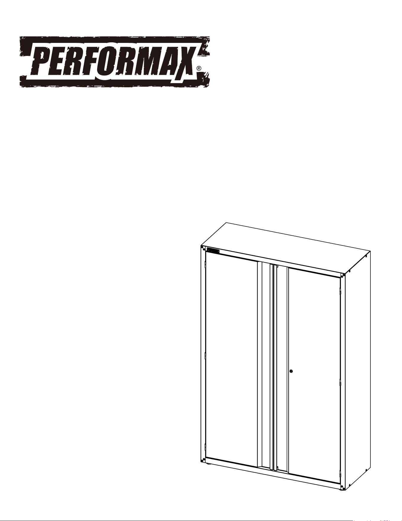
48 IN Tall Storage Cabinet
Table of Contents
Table of Contents .................................................. 2
Safety Information ............................................... 2
Warranty ................................................................ 3
Specifications ........................................................ 3
Package Contents .................................................. 3-4
Assembly ............................................................... 5-7
8............................... ................................ ecnanetniaM
Safety Information
To reduce the risk of injury, please read and follow the safety
instructions below before assembling and using this product.
1. This product is not designed for commercial or industrial
storage.
2. This product is intended for indoor use only.
3. Do not alter this product in any manner. For
example, do not weld external lock bars or attach
electrical equipment.
Do not stand on this product. You
may fall which may cause personal injury or
CAUTION: Keep the product on level surfaces.
The product may become unstable and tip if
stored or moved on an unlevel surface, which
may cause personal injury or product damage.
CAUTION:
Replacement Parts ................................................ 8
product damage.
2
Do not attach or mount this
product
to a vehicle or mobile trailers. This may cause
personal injury or product damage. Mounting this
product to any vehicle or mobile trailers in any
warranty.
CAUTION:
manner will void
It is recommended to secure this
product to the wall to prevent accidental tipping.
CAUTION:
CAUTION:
Lock the door
if
moving
this product. The doors
could come open and
make the product unstable and tip, which may
cause personal or product damage.
FF
Washer 2
Specifications
Maximum Load Capacity (per shelf)
150 lbs.
NOTE: Begin product assembly close to t nal
intended location of your cabinet. This product is
heavy and may be di
cult to move after assembly.
Package Contents
HARDWARE INCLUDED
NOTE: Hardware not shown to actual size.
ALTERNATIVE TOOLS FOR ASSEMBLY
(Not Included)
3
Limited Lifetime Warranty
PERFORMAX® tall cabinets are warranted to be free from defects in materials and workmanship under normal use for the lifetime
that you own the product. If any part of the product is found to be defective during normal use, the defective product or part will be replaced at
our discretion. This warranty does not cover products that are damaged through accident, abuse, misuse, commercial/industrial applications or
neglect. This warranty also does not cover any losses, injuries or costs including indirect, incidental or consequential damages. This warranty
may not be transferred or sold. When requesting warranty service please call 1-866-441-5080 and have the model number, cash register receipt
and the date of purchase available when you call. If the product is defective, we will replace the defective part at no cost to you. Some states
do not allow the exclusion or limitation of incidental damages, so the above limitations or exclusions may not apply to you. This warranty gives
Part Description
AA
M6x10 Screw 56
BB Shelf Mount 12
CC Leveling Feet 4
DD ST6.3x75 screw 2
EE Drywall Anchor 2
Quantity
BB
EE
CC
AA
DD
Power Drill
FF
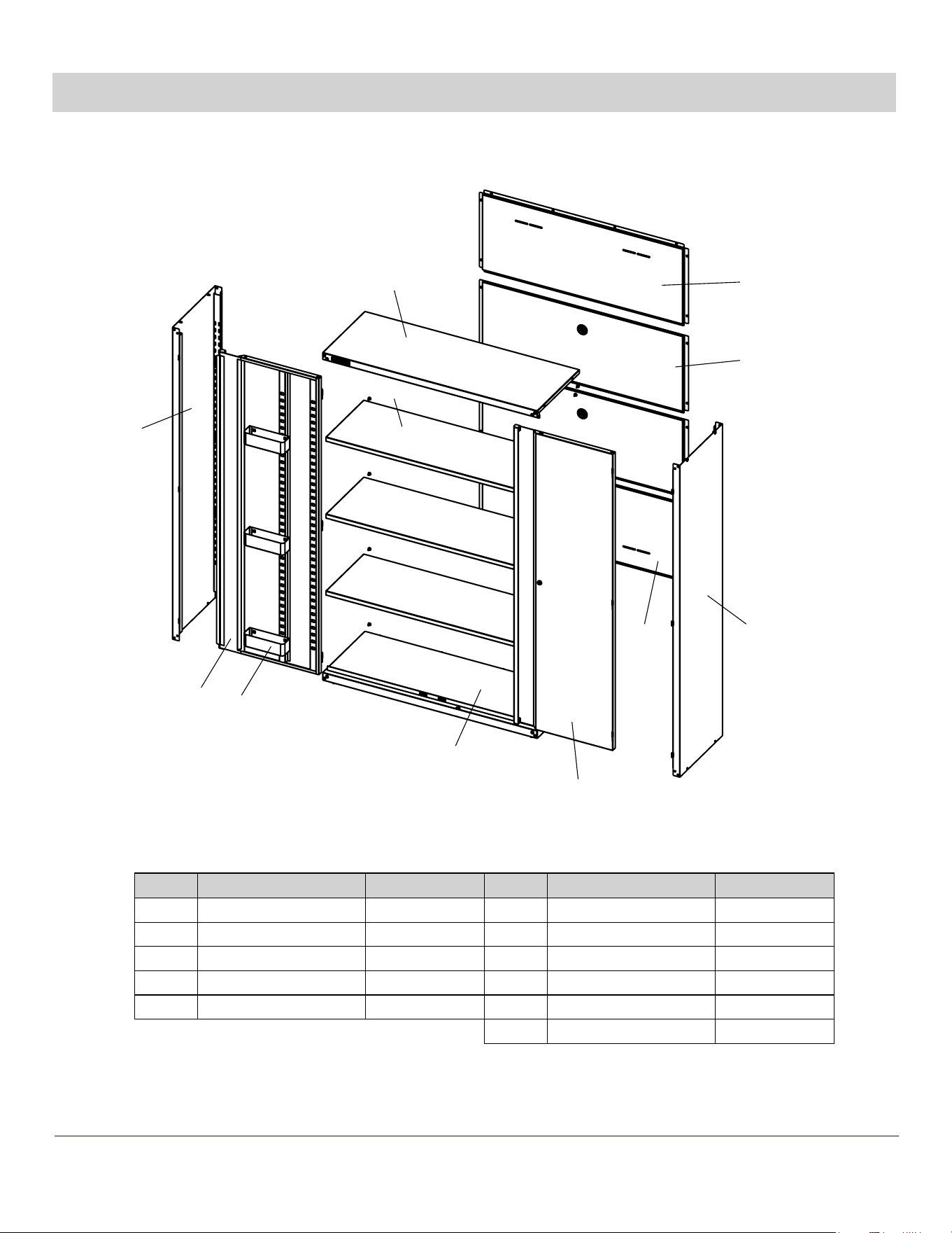
Package Contents (continued)
4
Part Description Quantity
A
B
Back Panel-top 1
Back Panel-middle 2
1Back Panel-bottomC
1Top PanelD
Part Description Quantity
G
H
Adjustable Shelf 3
Left Door 1
E
Left Side Plate 1
1Right Side Plate
F
1Right Door
I
J
Bottom Panel 1
K
Storage Tray 6
A
B
C
D
E
F
G
H
K
I
J
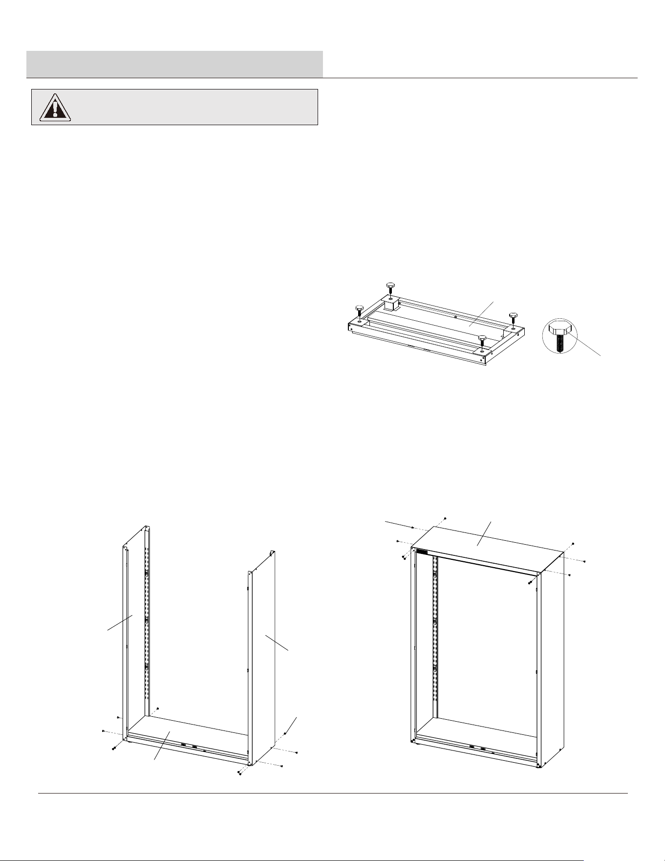
To assure the squareness of the unit, do not fully tighten the screws until the cabinet is fully assembled and level.
□
Remove all parts and hardware from the shipping box. Check the contents against the PARTS and
HARDWARE lists on the previous page. If parts or hardware are missing, please call 1-866-441-5080 for assistance.
□
Attaching the Leveling Feet
2
Attach the Leveling Feet (CC) to Bottom Panel (J)
and tighten.
□
Attaching the Side Panels
3
Attach Left Side Panel (E) and Right Side Panel (F) to
Bottom Panel(J) with 10 screws (AA).
Do not fully tighten.
□
□
4
Attaching the Top Panel
□
Attach Top Panel (D) to the Side Panels (E) and (F).
Align holes on the sides and back and secure with
10 screws (AA).
□
Do not fully tighten.
E
F
J
AA
AA
D
CC
J
Unpacking instructions
1
Assembly
CAUTION:
Two people are recommended for assembly.
5
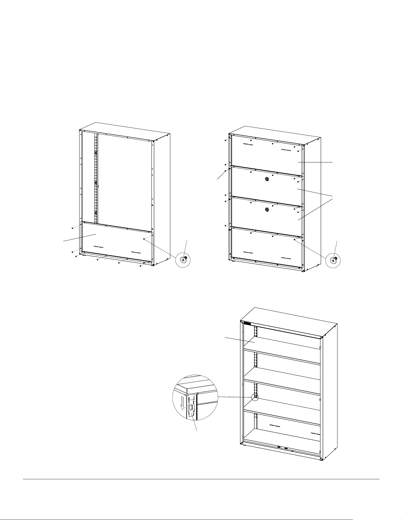
6
C
A
B
AA
AA
AA
Attaching Back Panel
5
Attach Back Panel-bottom (C) inside the two side panels and bottom. Align and insert 8 screws (AA) into holes but do
not fully tighten.
□
BB
Attach and install four of the Shelf Mounts (BB) for each shelf
to the front and rear corners.
6
□
Determine the desired height of your shelf.
□
Insert Adjustable Shelf (G) into cabinet.
□
Attaching Adjustable Shelf
G
Attach the two Back Panel-middle (B) inside the two side panels and bottom. Align and insert 16 screws (AA) into holes
but do not fully tighten.
□
Attach Back Panel-Top (A) inside the two side panels and bottom. Align and insert 12 screws (AA) into holes but do not
fully tighten.
□
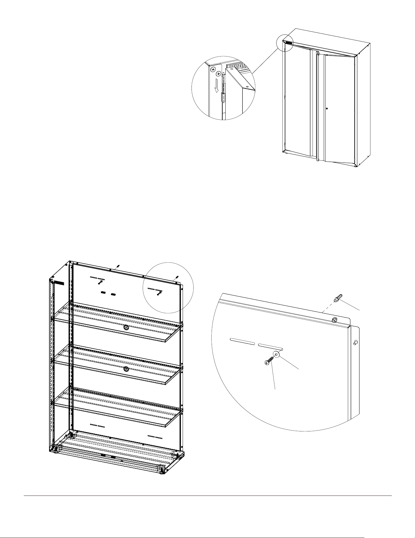
Securing to a Wall
8
Measure and mark the location of the left and right attachment holes on the wall.
Drill a 5/16” hole on the left and right side and insert the Drywall Anchor (EE) into the holes.
Use the ST6.3x75 screw (DD) and washer (FF) to secure each side of the the Back Panel (A) into the Drywall Anchor (EE).
□
□
DD
FF
EE
7
Attaching the door
7
□
□
Align the holes on the hinge of the Left Door (H)
to the holes on the Side Panel.
Repeat process for the right door
(I with lock assembly).
□
Once cabinet is square and level, go back and
tighten all screws used in assembly.
Note: To maintain proper operation of the
cabinet doors, ensure the cabinet is completely
level by adjusting the four Leveling Feet (CC).
□
Maintenance
Periodically the surfaces should be cleaned with a mild detergent and water.
Replacement Parts
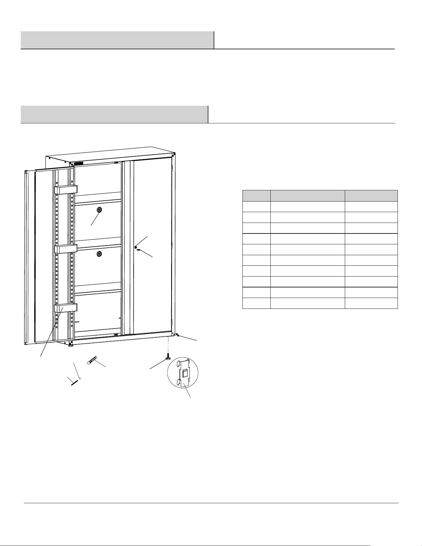
For assistance with replacement parts please call 1-866-441-5080.
8
C
Part Description Quantity
A
Rubber grommet 2
B
M6x10 Screw
56
C
Shelf Mount
12
D
Leveling Feet
4
E
ST6.3x75 screw
2
F
Drywall Anchor
2
G
Washer
2
H
Lock
1
I
Key
2
J
Storage Tray
6
A
B
D
E
F
G
H
I
J

