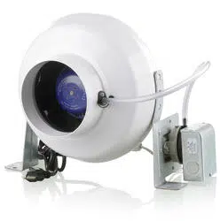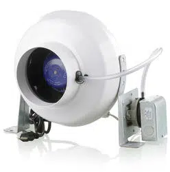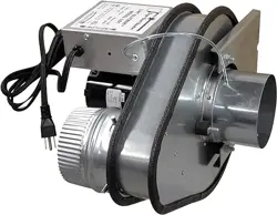
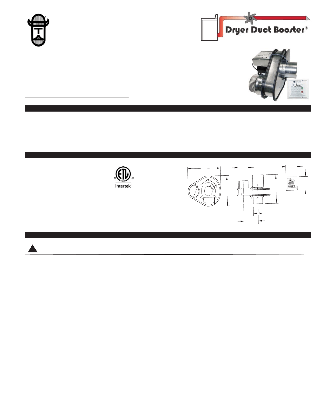
DESCRIPTION & PURPOSE
The LB2 is Listed to the updated DEDPV, Dryer Exhaust Duct Power Ventilator supplement to UL705 & CSA C22.2 #113-12. The 2015
IRC restricts the use of dryer booster fans to those tested to the DEDPV supplement. Incorporating dryer booster fans in clothes dryer
ducts has increased substantially with the placement of laundry rooms not adjacent to outside walls. Duct runs often exceed 25 equiva-
lent feet (90 degree elbows equal 5 additional feet of duct length, 45 degree elbows equal 2.5 feet) that many clothing dryer manufactur-
ers set as a maximum duct length. The LB2 booster fan is rated for duct lengths up to 150 equivalent feet.
SPECIFICATIONS & COMPONENTS
INSTALLATION RESTRICTIONS
This product has rotating parts, do not plug into power if duct is not connected on both ends of Dryer Duct Booster®.
The installation must comply with local electrical and mechanical, fuel gas, or building codes, and must be inspected and accepted by
local authorities having jurisdiction.
CAUTION: DO NOT INSTALL IN AN EXHAUST DUCTWORK OF A CLOTHES DRYER WHOSE INSTRUCTIONS PROHIBIT THE
INSTALLATION OF A CLOTHES DRYER BOOSTER FAN. ATTENTION: NE PAS INSTALLER DANS LE CONDUIT D’ÉVACUATION
DE LA SÉCHEUSE SI LES INSTRUCTIONS INTERDISENT L’INSTALLATION D’UN VENTILATEUR AUXILIAIRE.
CAUTION: DO NOT INSTALL IN AN EXHAUST DUCTWORK WHERE THE EQUIVALENT DUCT LENGTH IS LESS THAN OR
EQUAL TO 7.62 METERS (25 FT). ATTENTION: NE PAS INSTALLER DANS UN CONDUIT D’ÉVACUATION MESURANT 7,62
MÈTRES (25 PI) DE LONGUEUR OU MOINS.
CAUTION: Do not install less than 5 linear feet (1.524 Meters) from clothes dryer exhaust outlet.
Do not exhaust air in excess of 167
o
F (75
o
C).
The Dryer Booster Fan must be accessible after the installation is completed.
This Dryer Booster Fan may not be used in conjunction with dryers designated as high output.
WARNING - If no lights are on, or a blinking or solid Red LED is displayed on the Notification Panel turn off clothes dryer and reference
“Notification Panel Status Modes” section of these instructions on page 3.
WARNING - TO REDUCE THE RISK OF FIRE, ELECTRICAL SHOCK, OR INJURY TO PERSONS, OBSERVE THE FOLLOWING:
1) Your clothing dryer installation incorporates a dryer exhaust duct power ventilator (DEDPV) which may be in a different location than
your dryer, such as in an attic, crawl space or basement.
TJERNLUND PRODUCTS, INC.
1601 Ninth Street • White Bear Lake, MN 55110-6794
PHONE (800) 255-4208 • (651) 426-2993 • FAX (651) 426-9547
Visit our web site • www.tjernlund.com
READ OWNERS INSTRUCTIONS CARE-
FULLY PRIOR TO INSTALLATION. SAVE
THESE INSTRUCTIONS.
IMPORTANTES POUR LA SÉCURITÉ.
CONSERVEZ CES INSTRUCTIONS.
DRYER DUCT BOOSTER® FAN
MODEL LB2
MODEL LB2
Blower: 160 cfm
Motor: 115 Volts ~ 60 Hz
0.80 amps maximum
Impeller: Reverse inclined, particulate handling
Components: (1) LB2 wired fan assembly
(1) Notification Panel
(1) 16 gauge galvanized steel mounting bracket
(1) mounting hardware packet
©2015 TJERNLUND PRODUCTS, INC. ALL RIGHTS RESERVED P/N: 8504216
For Residential Capacity Clothes Dryers
UL705
CSA C22.2 #113-12
WARNING
!
14"
10.5"
OUTLET
INLET
4"
10"
6.25"
FIGURE 8061040 1/4/16
4"
4.75"
4.65"
LED
NOTIFICATION
WALL PLATE
R
R
2) Your clothing dryer depends on the DEDPV Booster Fan for its safe and efficient operation. Operating your dryer without a functional
DEDPV will result in inefficient dryer operation, excess energy consumption and a possible fire hazard. See warnings on the
Notification Panel.
3) The Notification Panel shall be permanently installed within the space in which the clothes dryer is installed. In the case of a dryer
installed in an alcove provided with a door or doors, the Notification Panel shall be permanently installed within the alcove or be
immediately adjacent to the doors of the alcove. The Notification Panel shall be located where it will be readily visible after the dryer
is installed without having to open any doors other than those necessary to access the dryer.
AVERTISSEMENT - POUR RÉDUIRE LE RISQUE D’INCENDIE, DE CHOC ÉLECTRIQUE OU DE BLESSURE,RESPECTER LES
CONSIGNES QUI SUIVENT:
1) Votre sécheuse est équipée d’un ventilateur auxiliaire qui peut être installé loin de la sécheuse,comme dans un grenier, un vide
sanitaire ou un sous-sol.
2) Le ventilateur auxiliaire est essentiel au fonctionnement sécuritaire de la sécheuse. Désactiver ce ventilateur nuira au fonctionnement
de la sécheuse, entraînera un augmentation de la consommation d’électricité et possiblement un risque d’incendie. Lire la mise en
garde sur le panneau d’indication d’alarme.
3) Le panneau d’alarme doit être installé de façon permanente dans l’espace où se trouve la sécheuse. Si la sécheuse est installée
dans une alcôve fermée par une porte, le panneau d’alarme doit être installé dans l’alcôve ou à proximité immédiate de la porte de
l’alcôve. Le panneau d’alarme doit être visible une fois la sécheuse installée sans avoir à ouvrir une porte autre que celle donnant
accès à la sécheuse.
The LB2 must be installed in an area in which ambient air temperatures are between -20° F and 140° F (-29° C and 60° C) and ambient
humidity does not exceed 85% relative humidity.
Do not install the LB2 in a position where dryer exhaust temperatures exceed 167°F (75° C) at LB2 inlet. LB2 thermal fuse is set at
186° - 196° F (86 - 91° C).
IMPORTANT: The dryer duct in which the LB2 is installed must
terminate with a dryer exhaust hood with a flapper or have a backdraft
damper installed near the exterior termination.
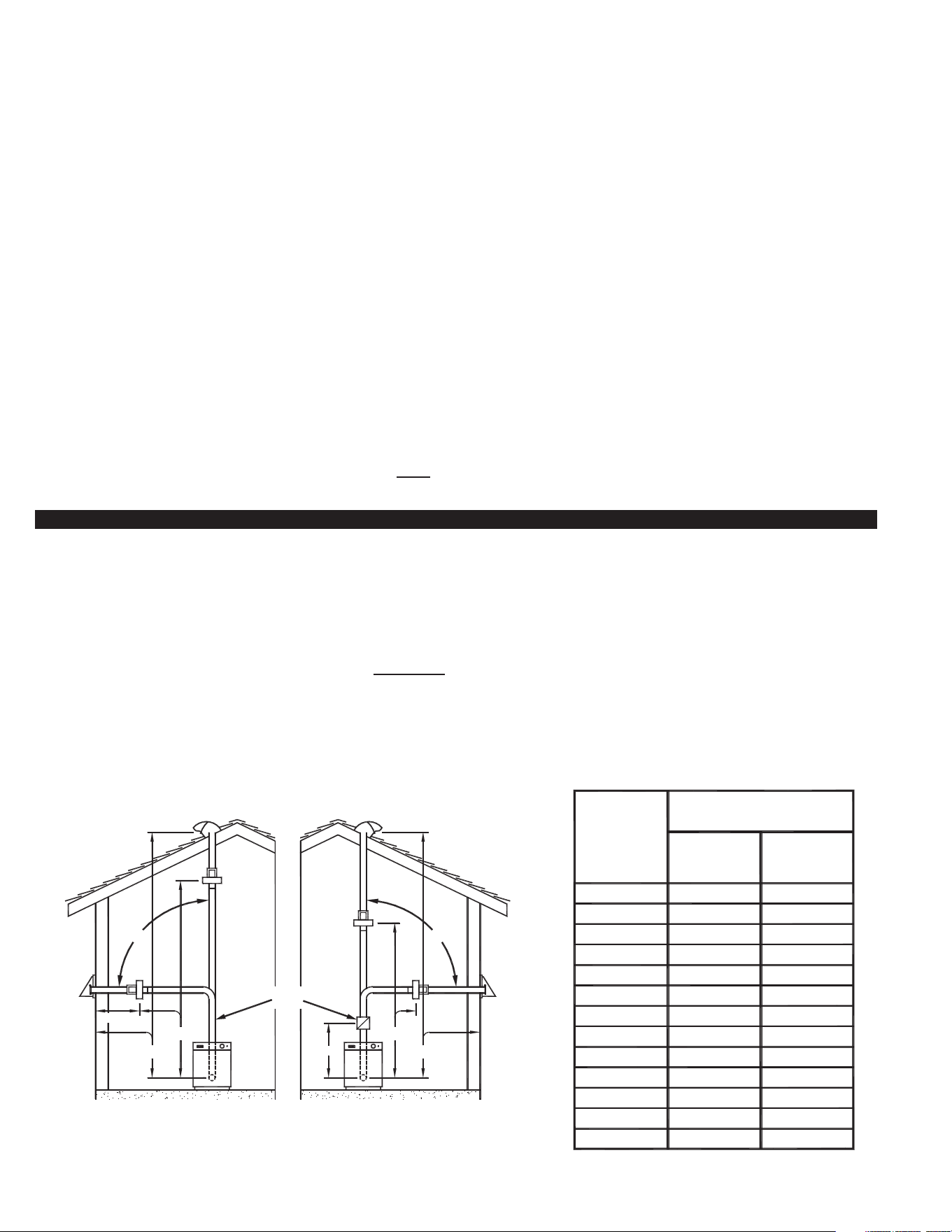
MINIMUM AND MAXIMUM DRYER DUCT LENGTH IN EQUIVALENT FEET*
This product is intended for use in 4” diameter dryer exhaust ducts from 30 to 150 equivalent feet* in length.
*Equivalent feet equals linear feet plus 5 additional feet for each 90° elbow and 2.5 feet for each 45° elbow
(assumes 4” diameter rigid metal duct).
Dryer Booster Fan Distance from Dryer and Termination Hood
The Dryer Booster fan positioning is based on the total Duct Length Equivalent Feet*. Calculate the Total Duct Length Equivalent
Feet and reference how close the Dryer Booster can be installed to the Dryer without a Secondary Lint Trap (Column X) or with
a Secondary Lint Trap (Column Y). The Dryer Booster should not
be installed closer to the Dryer than what is indicated in those
columns. If a Secondary Lint Trap (Tjernlund model LT4) is needed, it must be installed about 4 linear feet from the Dryer and the
Booster must be installed after the Secondary Lint trap (between the Secondary Lint Trap and outdoor termination hood).
For best performance install Dryer Booster no closer than 2 feet from the termination to the outdoors and avoid installing elbows within
2 feet of the Dryer Booster.
Lint Trap 4 Feet
With Secondary
from Dryer (Y)
30
40
50
60
70
80
90
100
110
120
130
140
150
45
45
45
30
30
35
35
40
40
40
15
20
25
25
20
20
8
10
10
15
15
20
20
8
8
8
Length In
Equivalent Feet*
Total Duct
LB2 Minimum Distance from Dryer
In Equivalent Feet*
(A)
Lint Trap (X)
With No
Secondary
1
RESIDENTIAL
FIGURE 8052084 5-7-15
DRYER DRYER
RESIDENTIAL
OR
NO
LINT TRAP
SECONDARY
DRYER
VENT WITH
DAMPER
WITH DAMPER
DRYER ROOF VENTDRYER ROOF VENT
WITH DAMPER
LB2 LB2
LB2
LB2
4 FT.
OR
X
2 FT. MIN.
A = DRYER VENT DUCT TOTAL EQUIVALENT LENGTH.
X = SHORTEST DISTANCE LB2 CAN BE TO DRYER WITHOUT SECONDARY LINT TRAP. SEE TABLE.
A
Y
A
OR
DAMPER
VENT WITH
DRYER
SECONDARY
LINT TRAP
WITH
NO SECONDARY WITH SECONDARY
LINT TRAP LINT TRAP
Y = SHORTEST DISTANCE LB2 CAN BE TO DRYER WITH SECONDARY LINT TRAP. SEE TABLE.
MOUNTING DRYER DUCT BOOSTER
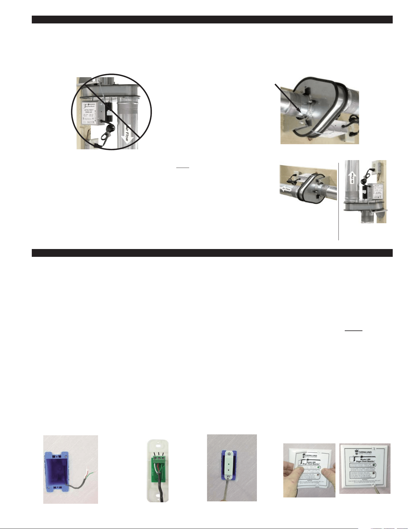
Do not install the LB2 with the discharge facing down, (See Diagram A).
Do not install the LB2 in an orientation where the sensing tube port points directly down where it might fill with condensation. By design,
the sensing tube port is offset so it does not point directly down in this mounting orientation. If the LB2 is mounted to warped or not
square material, the sensing tube may end up pointing directly down where condensation can pool in sensing tube port, (See Diagram B).
NOTE: Do not use screws in the dryer duct installation. The LB2 motor can be mounted in
a horizontal or vertical orientation. Discharge must
face up if mounted vertically,
(See Diagram C). Do not install the LB2 in an orientation where the sensing tube
port might fill with condensation, (See Diagram B).
1. Considering dryer duct routing and LB2 location, use the (4) #10 x 1 3/4" wood screws to
secure the mounting bracket to the wood structure using the (4) 3/8" holes in the ½ moon
portion of the bracket.
2. Based on the desired mounting orientation, position the mounting bracket onto 3 of the 4
vibration isolators located on the LB2. Tighten the bracket in place using the (3) provided
1/4” nuts. Do not over tighten or damage to rubber mounting isolators may occur.
3. Insert dryer duct on inlet and outlet of LB2 and secure using reinforced foil duct tape.
MOUNTING DRYER BOOSTER NOTIFICATION PANEL (MOUNT IN VISIBLE LOCATION BY CLOTHES DRYER)
IMPORTANT: The Notification Panel shall be permanently installed within the space in which the clothes dryer is installed. In the case
of a dryer installed in an alcove provided with a door or doors, the Notification Panel shall be installed permanently within the alcove or
immediately adjacent to the doors of the alcove. The Notification Panel shall be located where it will be readily visible after the dryer is
installed without having to open any doors other than those necessary to access the dryer.
NOTE: The Dryer Duct Booster includes a 50’ control cable. If the distance between the Notification Panel and the Dryer Duct Booster
is greater than the length of the cable, splice a section of 3 conductor PVC sheathed 19 AWG or larger, 105 degree C thermostat cable
to the supplied cable. Make sure the color coded leads remain consistent. An NEC approved accessible junction box and cover must be
used to contain the splice. Splices shall be made mechanically secure and insulated with appropriately sized wire nuts or with a similarly
approved connection method. Strain relief hardware contained within the NEC approved junction box shall be utilized. Do not
use an
existing line voltage electrical box to house these low voltage connections. Line voltage to these leads will cause damage to the LB2
control system and may cause personal and/or property damage.
The Notification Panel Terminal Block may be installed in a remodeling or standard electrical box or without an electrical box.
INSTALLING NOTIFICATION PANEL WITH AN ELECTRICAL BOX
1. Install standard or remodeling single gang electrical box and route control wire from LB2 into electrical box and leave hanging out for
connection to Notification Panel, (See Diagram D).
2. Wire White, Red & Green wires from Dryer Booster cable to Notification Panel terminal block as shown, (See Diagram E)
3. Carefully stuff wires into electrical box, screw Notification Panel terminal block mounting plate to electrical box with Green LED
light on top, (See Diag. F). Adhere Notification Panel label to coverplate & screw coverplate to notification panel holder with provided
screws, (See Diagram G).
2
DIAGRAM D
DIAGRAM F
DIAGRAM E
WHITE
RED
GREEN
DIAGRAM G
DIAGRAM B
IF INSTALLING THE LB2 IN
THIS ORIENTATION, MAKE
SURE THE SENSING PORT
DOES NOT POINT DIRECTLY
DOWN WHERE CONDENSA-
TION CAN POOL IN SENSING
TUBE PORT. THIS MIGHT
OCCUR IF LB2 IS MOUNTED
TO MATERIAL THAT IS
WARPED OR NOT SQUARE.
DIAGRAM A
DIAGRAM C
HORIZONTAL
MOUNTING
VERTICAL MOUNTING
MUST DISCHARGE
FACING UP
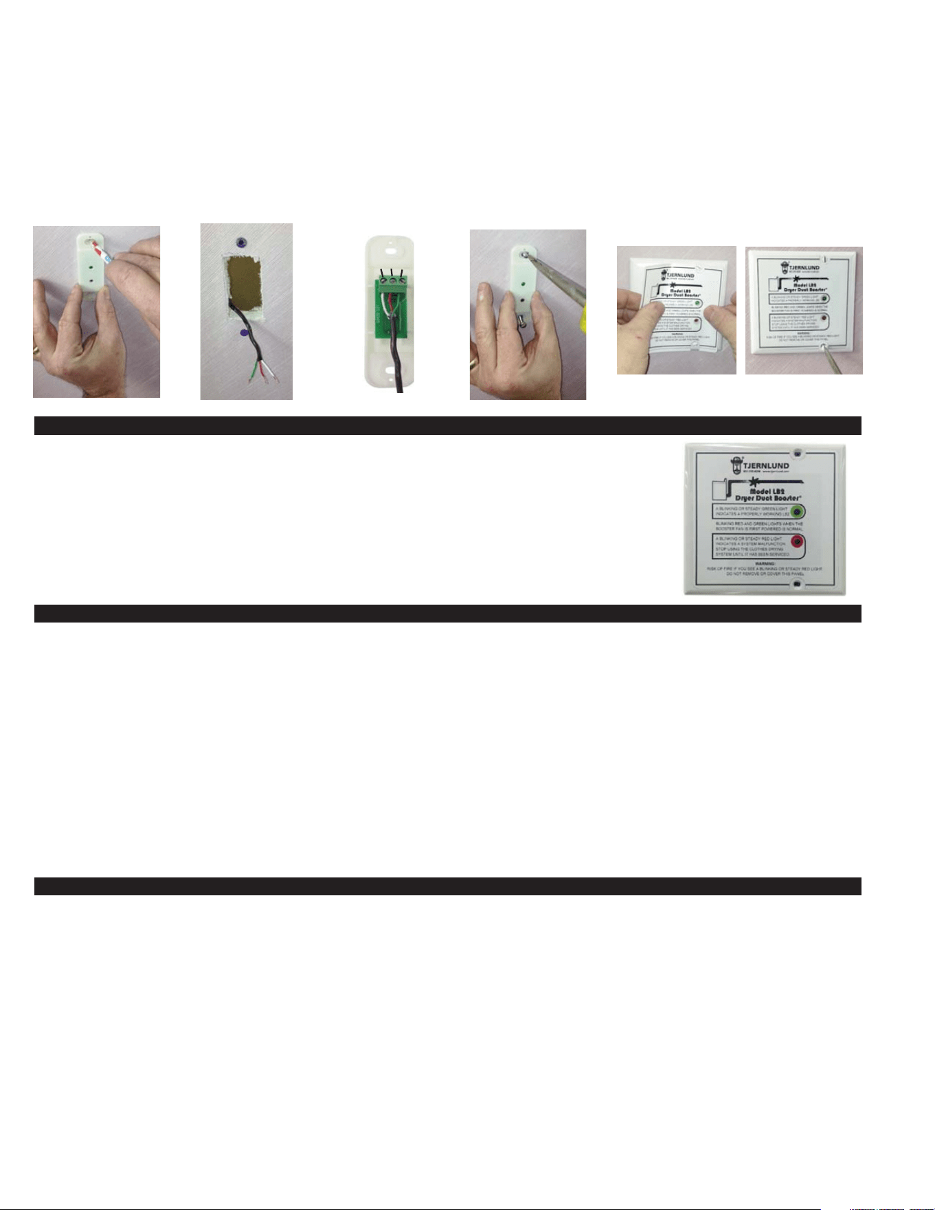
INSTALLING NOTIFICATION PANEL WITHOUT AN ELECTRICAL BOX
1. Cut opening in sheetrock 1-1/4” wide by 2-1/4” tall, hold Notification panel terminal block mounting plate over opening and mark top
and bottom holes for wall anchors, (See Diagram H). Once marked, drill 3/16” holes for wall anchors and feed control cable through
opening, (See Diagram I).
2. Wire White, Red & Green wires from Dryer Booster cable to Notification Panel terminal block as shown, (See Diagram J)
3. Adhere Notification Panel label to coverplate and screw coverplate to electrical box with provided screws, (See Diagram G). Screw
Notification Panel terminal block holder to wall anchors with Green LED light on top, (See Diagram K). Adhere Notification Panel label
to coverplate and screw coverplate to notification panel holder with provided screws, (See Diagram L).
DRYER
BOOSTER
NOTIFICATION PANEL STATUS LIGHTS
Flashing Red and Green LED’s...Control calibrates to exhaust duct pressure drop when 1st plugged in
Slow Flashing Green LED............Idle state, No dryer operation sensed
Fast Flashing Green LED............Sensor is detecting dryer turning on or off
Steady Green LED.......................Dryer Booster Fan on
Flashing Red LED........................Blockage sensed or Dryer Booster Fan not operating
Steady Red LED..........................High temps detected, Dryer Booster Fan is shut off
LB2 CALIBRATION PROCEDURE
IMPORTANT: Make sure all of the following are performed before supplying power to the LB2.
• Confirm the LB2 and the entire duct system is completely installed and clear of lint. (Required for proper calibration.)
• Confirm the dryer is off and cool.
• Confirm all lint traps are empty of lint and reinstalled in their proper position.
• Confirm the Dryer is Empty of Clothing.
• Confirm the Door on the Dryer is Closed.
• Supply Power to the LB2 by plugging in the power cord or cycling the power circuit the LB2 is plugged into.
NOTE: Within 45 seconds of the LB2 Dryer Booster being supplied power, it will come on and run for up to 45 seconds. This is a cali-
bration period and will only happen when the LB2 is first powered. During this time the Red and Green LED’s on the Notification Panel
will both flash quickly in an alternating sequence. Once the calibration process is over, only the Green light will flash and at a much
slower pace.
Once the LB2 has been calibrated and just the Green light is flashing on for 1/2 second, off for 2 seconds, the clothes dryer can be used.
NOTIFICATION PANEL STATUS MODES
MONITOR MODE: (Green LED blinks 1/2 second on, 2 seconds off)
• When the dryer is not operating, the Green LED on the Notification Panel will blink for 1/2 second on, 2 seconds off. This is normal
operation and is an indication that the LB2 is ready for the Dryer to come on.
DRYER TRANSITION MODE: (Green LED flashes rapidly)
• When the dryer is turning on or off, the LB2 senses the change in pressure. During this time period, the Green LED will flash rapidly
1/2 second on, 1/2 second off.
PROPER VENTING MODE: (Green LED continuously on)
• When the LB2 is on, the Green LED will be continuously on.
PRESSURE FAULT MODE: (Red LED flashing)
• If at anytime during the calibration or operating cycle of the LB2 and the Dryer there is excessive pressure sensed, the Notification
Panel will flash the Red LED. The LB2 will continue to operate to try and clear the blockage. Stop the dryer immediately and have the
vent system inspected by someone qualified to do so. The power to the LB2 will need to be removed to clear the fault condition and
turn the LB2 motor off. The LB2 calibration cycle will need to be performed. (See LB2 Troubleshooting for complete details)
DIAGRAM H
DIAGRAM K
DIAGRAM I
DIAGRAM J
WHITE
RED
GREEN
GREEN
RED
DIAGRAM L
3
TEMPERATURE FAULT MODE: (Red LED solid)
• If an excess temperature is sensed by the LB2, the LB2 motor will shut off and a constant Red LED will be on at Notification Panel.
Stop the dryer immediately and have the vent system inspected by someone qualified to do so. The power to the LB2 will need to be
removed to clear the fault condition and the LB2 Calibration Procedure will need to be performed. (See LB2 Troubleshooting for com-
plete details)
NOTIFICATION PANEL HAS NO LIGHTS:
• The Notification Panel should always have a Green LED light on in at least a slow flash mode (1/2 second on, 2 seconds off). Do Not
operate the dryer if there is no Green LED. If no lights are illuminated on the Notification Panel for greater than 5 seconds, there is an
issue with the LB2 installation or the LB2. Confirm the LB2 has Power and that the Notification Panel has been installed (Wired) cor-
rectly. If the dryer is operating and there is no Green LED on the Notification Panel, stop the dryer immediately and have the vent
system inspected by someone qualified to do so. Contact Tjernlund at 1-800-255-4208 with further questions. (See LB2
Troubleshooting for complete details)
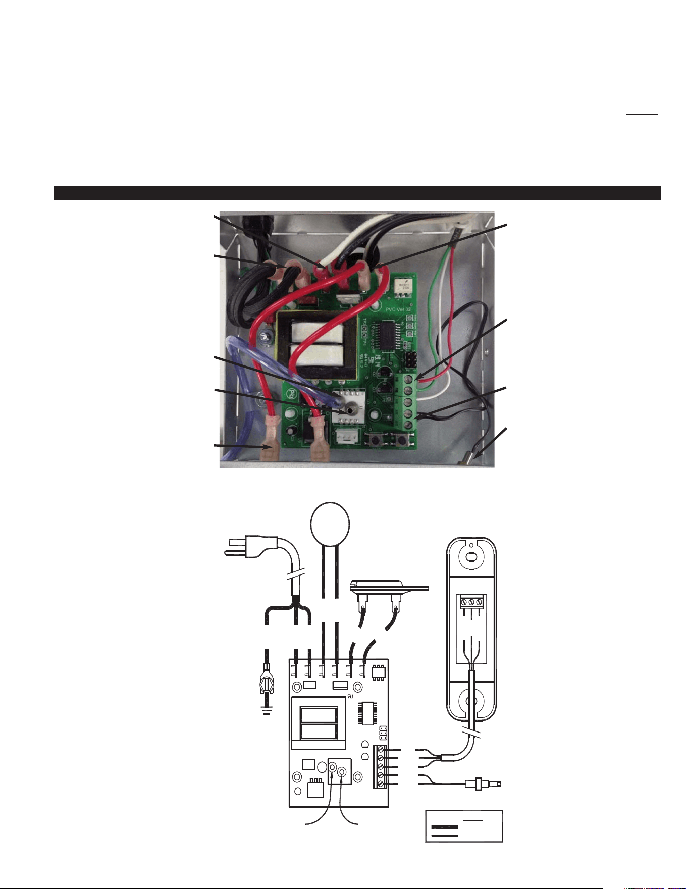
LB2 ELECTRICAL BOX COMPONENTS
LB2 ELECTRICAL BOX WIRING CONNECTIONS (INSTALLER MUST CONNECT WIRES TO NOTIFICATION PANEL)
Notification Panel
Connections
(Top to Bottom)
Red, Green, White
115 VAC
Power Cord
Connections
Motor
Connections
Reference Port
Important: Do not connect
sensing tube here.
Sensing Port
Thermal Fuse
Connections
Thermistor
Connections
Thermistor
Thermal Fuse
Connections
J1
J2
J3
J4
J5
J6
94V
-
0
-
THERMISTOR
RED
GREEN
WHITE
BLACK
BLACK
RED
GREEN
WHITE
MOTOR
LB2
WHITE
BLACK
RED
RED
THERMAL FUSE
GND R G
GREEN
WHITE
BLACK
(N)
(L1)
6' POWER CORD
115 / 1 / 60
REFERENCE PORTSENSING TUBE
BY INSTALLER)
LEGEND
LINE VOLTAGE
LOW VOLTAGE
(WIRES CONNECTED
PANEL
NOTIFICATION
CONNECTION PORT
(LEAVE OPEN)
4
MAINTENANCE & SERVICE
Reference Dryer Manufacturer’s recommendations for Dryer exhaust vent cleaning and maintenance. Depending on use, but at least
every 2 years, we recommend cleaning the dryer exhaust vent. On an annual basis make sure that exhaust hood flapper or backdraft
damper is clean of lint and moves freely. The LB2 motor is maintenance free. If the LB2 is acting erratically, perform the calibration pro-
cedure as outlined on page 3. The fan impeller is designed for particulate handling, however, if cleaning is needed perform the steps
below.
WARNING: Do not blow into the pressure sampling tube in the direction of the circuit board. The pressure sensor is a very sensi-
tive device that can be destroyed if subjected to the pressure created by someone blowing strongly into it.
CLEANING INSTRUCTIONS
WARNING: Disconnect Power to the LB2 before servicing.
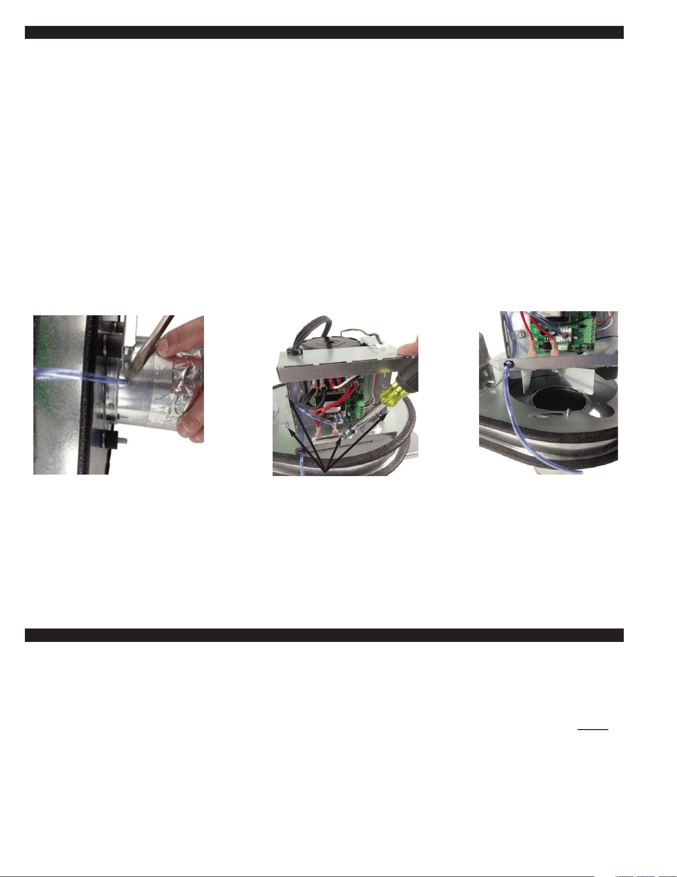
1. Loosen the electrical box cover screws from the LB2 using a ¼" nut runner to access the housing cover plate stud within the box.
2. Carefully remove sensing tube from inlet pipe by prying loose with a screwdriver, (See Diagram M).
3. Remove the (6) 8-32 nuts from the outside edges of the housing cover plate, (See Diagram N).
4. Carefully remove the Motor / Impeller assembly by lifting the assembly straight off the housing studs, (See Diagram O).
5. Clean the Impeller and Housing
6. Reassemble in the reverse order.
7. Re-calibrate the LB2. See LB2 Calibration Procedure on page 3.
If you have any questions about your LB2 we suggest that you contact your installer, contractor or service agency. If you require
technical information contact Tjernlund Products, Inc. at 1-800-255-4208 or visit www.tjernlund.com.
When contacting Tjernlund Products, Inc., please have the following information available:
1. Name and address of installer and service agency.
2. Job code on nameplate, date of original installation and dates any service work was performed.
LB2 TROUBLESHOOTING
IMPORTANT: All faults are indicated by the Red LED light or no Lights on Notification Panel. Faults must be investigated as outlined
below and must only be cleared once a thorough investigation of the dryer vent system and dryer has been performed by someone
qualified to do so. Perform LB2 Calibration Procedure on Page 3 to clear any faults once investigation is complete.
NOTIFICATION PANEL HAS NO LIGHTS:
The Notification Panel should always have a Green LED light on in at least a slow flash mode (1/2 second on, 2 seconds off). Do Not
operate the dryer if there is no Green LED. If no lights are illuminated on the Notification Panel for greater than 5 seconds, there is an
issue with the LB2 installation or the LB2. Confirm the LB2 has Power and that the Notification Panel has been installed (Wired) correct-
ly. If the dryer is operating and there is no Green LED on the Notification Panel, stop the dryer immediately and have the vent system
inspected by someone qualified to do so. Contact Tjernlund at 1-800-255-4208 with further questions.
PRESSURE FAULT MODE: (Red LED flashing)
If at anytime during the calibration or operating cycle of the LB2 and the Dryer there is excessive positive pressure of +0.16” W.C.
sensed for over four minutes, the Notification Panel will flash the Red LED. Stop the dryer immediately and have the vent system
inspected by a qualified person. This is an indication of excessive back pressure in the vent system. Verify LB2 is located per Minimum
DIAGRAM M
DIAGRAM N DIAGRAM O
CAREFULLY REMOVE SENSING TUBE
FROM INLET PIPE BY PRYING LOOSE WITH
A SCREWDRIVER UNDERNEATH TUBING.
REMOVE (6) 8-32 NUTS FROM OUTSIDE
EDGES OF MOTOR / IMPELLER ASSEMBLY.
CAREFULLY REMOVE MOTOR /
IMPELLER ASSEMBLY.
5
DESCRIPTION PART NUMBER
Sensing Tube Kit 950-9130
LB2 Circuit Board 950-9134
Motor Kit 950-9101
Thermal fuse Kit 950-9132
Thermistor Kit 950-9133
Notification Assembly Kit 950-9131
Secondary 4” Lint Trap LT4
WHAT IS NOT COVERED
Product installed contrary to our installation instructions.
Any freight charges related to the return of the defective part.
Product that has been altered, neglected or misused.
TJERNLUND LIMITED FIVE YEAR MATERIAL AND NO-CLOG WARRANTY
Tjernlund Products, Inc. warrants to the original purchaser of this product that the product will be free from defects due to faulty material or workmanship for a period of (5)
years from the date of original purchase or delivery to the original purchaser, whichever is earlier. Remedies under this warranty are limited to repairing or replacing, at our
option, any product which shall, within the above stated warranty period, be returned to Tjernlund Products, Inc. at the address listed below, postage prepaid. Additionally,
Tjernlund warrants to the original purchaser of this product that the unit will not become inoperable due to lint blockages that restrict the impeller’s motion for a period of (5)
years from the date of original purchase or delivery to the original purchaser, whichever is earlier. THERE ARE NO WARRANTIES WHICH EXTEND BEYOND THE
DESCRIPTION ON THE FACE HEREOF, AND TJERNLUND PRODUCTS, INC. EXPRESSLY DISCLAIMS LIABILITY FOR INCIDENTAL OR CONSEQUENTIAL DAM-
AGES ARISING FROM THE USE OF THIS PRODUCT. THESE WARRANTIES ARE IN LIEU OF ALL OTHER EXPRESS WARRANTIES AND NO AGENT IS AUTHO-
RIZED TO ASSUME FOR US ANY LIABILITY ADDITIONAL TO THOSE SET FORTH IN THESE LIMITED WARRANTIES. IMPLIED WARRANTIES ARE LIMITED TO THE
STATED DURATION OF THIS LIMITED WARRANTY. Some states do not allow limitation on how long an implied warranty lasts, so that limitation may not apply to you. In
addition, some states do not allow the exclusion or limitation of incidental or consequential damages, so that above limitation or exclusion may not apply to you. This war-
ranty gives you specific legal rights and you may also have other rights which may vary from State to State. Send all inquiries regarding warranty work to
Tjernlund Products, Inc. 1601 9th Street, White Bear Lake, MN 55110-6794. Phone (651) 426-2993 • (800) 255-4208 • Fax (651) 426-9547 • Email [email protected].
Distance Chart From Dryer on page 1. Move LB2 further away from dryer if necessary. Make sure termination hood flapper or backdraft
damper opens. Check for blockage in vent between LB2 and hood. Verify the LB2 motor is coming on when the dryer turns on. If the
motor is not turning on, make sure the dryer and vent is completely cool and perform the LB2 Calibration Procedure on Page 3. If motor
still does not turn on after being recalibrated, remove power from the LB2 and remove the RED leads from thermal fuse and check for
continuity across the thermal fuse, if open replace fuse and inspect dryer vent system and dryer thoroughly for signs of vent blockage
and high heat. If thermal fuse is closed replace RED leads on fuse and apply 115 VAC to LB2 motor leads to verify motor is good. If
motor is good, replace LB2 circuit board. If motor is bad, replace motor.
If there is excessive negative pressure over -1.00” W.C. sensed, that might be an indication that the dryer vent run is too long on inlet
side of LB2 or the dryer lint trap or any secondary lint trap, if installed, needs to be cleaned. Clean Dryer and Secondary Lint Traps and
verify total equivalent vent length and LB2 mounting location conforms with Minimum and Maximum Dryer Duct Length Section on Page
1. Move LB2 closer to dryer if necessary. Perform LB2 Calibration Procedure on Page 3 to clear any faults once investigation is complete.
TEMPERATURE FAULT MODE: (Red LED solid)
If at anytime excessive temperature is sensed by the LB2 thermistor for 15 seconds, the LB2 will shut off and display a constant Red
LED. Stop the dryer immediately and have the vent system inspected for signs of blockage or high heat by a qualified person. Remove
power from the LB2 and remove the RED leads from thermal fuse and check for continuity across the thermal fuse, if open replace fuse
and inspect dryer vent system and dryer thoroughly for signs of vent blockage and high heat. Perform LB2 Calibration Procedure on
Page 3 to clear any faults once investigation is complete.
REPLACEMENT PARTS AND WARRANTY
6