Installaon Instrucons and
Use & Care Guide
Keep this manual in the pocket on heater for future reference whenever maintenance, adjustment or service is required.
Retain your original receipt as proof of purchase.
DO NOT RETURN THIS UNIT TO THE STORE
Read this manual and the labels on the water heater before you install,
operate, or service it. If you have diculty following the direcons, or
aren’t sure you can safely and properly do any of this work yourself:
• Call your Local plumbing supplies store to have this water heater installed.
Professional Installaon is available for this product and the work is guaranteed.
• Schedule an appointment with a qualied person to install your water heater.
• Call our Technical Assistance Hotline which is listed on the water heater’s
warranty sheet. We can help you with installaon, operaons, troubleshoong,
or maintenance. Before you call, write down the model and serial number from
the water heater’s data plate.
Incorrect installaon, operaon, or service can damage the water heater, your
house and other property, and present risks including re, scalding, electric shock,
and explosion, causing serious injury or death.
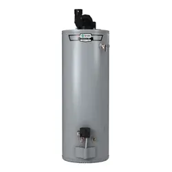
Residenal Gas
Water Heater
Residenal Direct Vented Gas Water Heater
Not for use in Manufactured (Mobile) Homes
100369451_2000626161_REV.A
Do not store or use gasoline or other
ammable vapors and liquids in the
vicinity of this or any other appliance.
WHAT TO DO IF YOU SMELL GAS
• Do not try to light any appliance.
• Do not touch any electrical switch;
do not use any phone in your build-
ing.
• Immediately call your gas supplier
from a neighbor’s phone. Follow the
gas supplier’s instrucons.
• If you cannot reach your gas suppli-
er, call the re department.
Installaon and service must be per-
formed by a qualied installer, service
agency or the gas supplier.
WARNING: If the informaon in
these instrucons is not followed
exactly, a re or explosion may
result causing property damage,
personal injury or death.
LOW LEAD
C
O
NTENT
June, 2023
Table of Contents
Important Safety Informaon .................................................. 3
Geng Started ........................................................................ 7
Installaon ............................................................................. 15
Operaon .............................................................................. 24
Troubleshoong .................................................................... 26
Maintenance ......................................................................... 30
Repair Parts ........................................................................... 33
Notes .................................................................................. 35
2 • Residenal Gas Water Heater Use and Care Guide
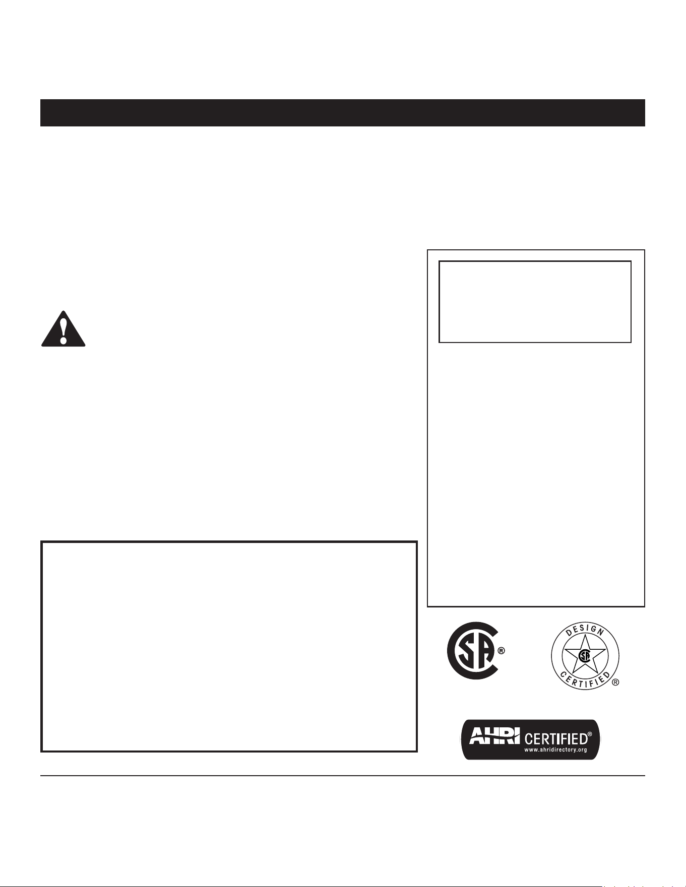
COMPLETED INSTALLATION (TYPICAL)
Vent Termination Hood
Wall Plate
Inlet Water
Shut-off Valve
Inlet Water
Shut-off Valve
Temperature and Pressure
Relief Valve
Combo Heating System
Supply Outlet (Optional)
Discharge Pipe
Combo Heating System
Supply Return Inlet (Optional)
Floor Drain
Drain Pan
Manual Gas
Shut-off
Drip Leg
Gas Control Valve/
Thermostat
Hot Outlet
Cold Inlet
Vent Pipe
Residenal Gas Water Heater Use and Care Guide • 3
IMPORTANT SAFETY INFORMATION
SAFETY
Read and follow all safety messages and instrucons in this
manual.
This is the safety alert symbol. It is used to alert you to
potenal physical injury hazards. Obey all safety messages
that follow this symbol to avoid possible property damage,
serious injury or death. Do not remove any permanent
instrucons, labels, or the data plate from either the outside
of the water heater or on the inside of the access panels. Keep this manual
near the water heater.
WARNING! If the informaon in these instrucons is not followed
exactly, a re or explosion may result causing property damage, personal
injury or death. Do not store or use gasoline or other ammable vapors and
liquids in the vicinity of this or any other appliance.
An odorant is added by the gas supplier to the gas used by this water heater.
This odorant may fade over an extended period of me. Do not depend upon
this odorant as an indicaon of leaking gas. We recommend installing a fuel
gas and carbon monoxide detector.
This product is cered to comply with a maximum weighted average of
0.25% lead content as required in some areas.
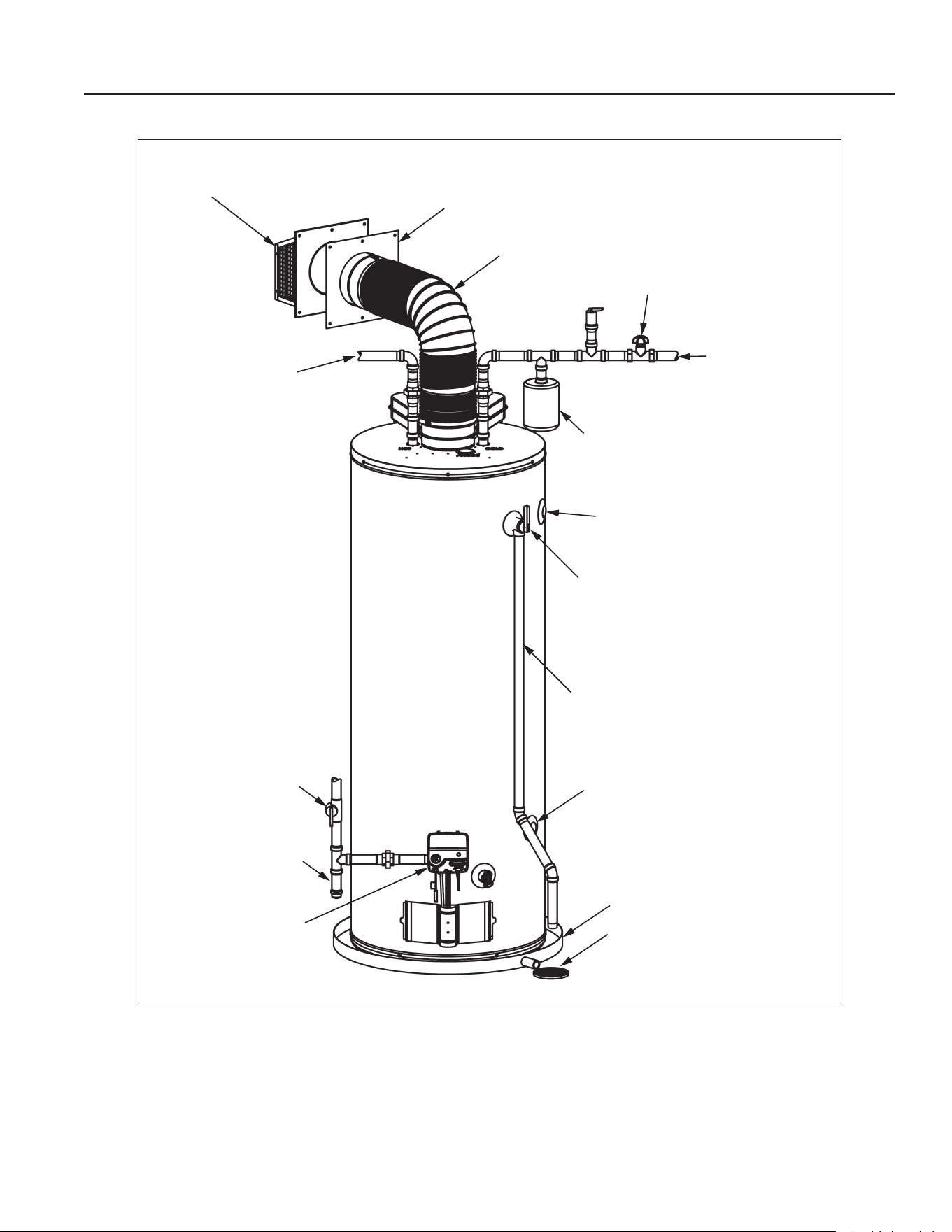
DANGER indicates a hazardous
situaon that, if not avoided, will
result in death or serious injury.
WARNING indicates a hazardous
situaon that, if not avoided, could
result in death or serious injury.
CAUTION indicates a hazardous
situaon that, if not avoided, could
result in minor or moderate injury.
NOTICE indicates pracces not
related to physical injury.
DANGER
WARNING
CAUTION
NOTICE
*Drain and flush tank and remove and
inspect anode rod after first six months
of operation and at least annually
thereafter. Operate the Temperature
and Pressure Relief Valve (T&P) annually
and inspect T&P valve every 2-4 years
(see the label on the T&P valve for
maintenance schedule). If no label is
attached to the T&P Relief Valve, follow
the instructions in the T&P Relief Valve
Maintenance section of this manual.
See the Maintenance section for more
information about maintaining this
water heater.
Important informaon to keep
Fill out this secon and keep this manual
in the pocket of the water heater for
reference.
Date Purchased:
Model Number:
Serial number:
Maintenance performed:* Date:
4 • Residenal Gas Water Heater Use and Care Guide
To reduce the risk of property
damage, serious injury or death, read
and follow the precauons below,
all labels on the water heater, and
the safety messages and instrucons
throughout this manual.
RISKS DURING
INSTALLATION AND
MAINTENANCE
Liing Risk
WARNING! The
water heater is
heavy. Follow these
precauons to reduce the risk of
property damage, injuries from liing
or impact injuries from dropping the
water heater.
• Use at least two people to li the
water heater.
• Be sure you both have a good grip
before liing.
• Use an appliance dolly or hand truck
to move the water heater.
Explosion Risk
WARNING! Read the
water heater’s data
plate to determine the type of gas
required. Failure to follow these
instrucons can result in serious
injury or death from explosion, re
or carbon monoxide poisoning.
• Do not connect a natural gas water
heater to an L.P. gas supply.
• Do not connect an L.P. gas water
heater to a natural gas supply.
• Use a new CSA approved gas supply
line.
• Install a shut-o valve on the gas
supply line.
Gas Pressure
WARNING! The gas supply
pressure must not exceed the
maximum supply pressure as stated
on the water heater’s data plate. The
minimum supply pressure is for the
purpose of input adjustment. L.P.
gas supply pressure must not exceed
13” water column. Have a qualied
person (licensed plumber, gas
company personnel, or authorized
service technician) check for proper
L.P. gas pressure. L.P. gas pressures
exceeding 13” water column can
result in serious injury or death from
explosion or re.
RISKS DURING
OPERATION
Scalding Risk
This water heater
can make water hot
enough to cause
severe burns instantly, resulng in
severe injury or death.
• Feel water before bathing or show-
ering.
• To reduce the risk of scalding, install
Thermostac Mixing Valves (tem-
perature liming valves) at each
point-of-use. These valves automa-
cally mix hot and cold water to limit
the temperature at the tap. Mixing
valves are available at your local
plumbing supplier. Follow the man-
ufacturer’s instrucons for installa-
on and adjustment of the valves.
• The gas control valve on this water
heater has been factory set to its
lowest seng to reduce the risk
of scalding. Higher temperatures
increase the risk of scalding, but even
at 120°F, hot water can scald. If you
choose a higher temperature seng,
Thermostac Mixing Valves located
at each point-of-use are parcularly
important to help avoid scalding.
Table 1
Temperature Time to Produce a
Serious Burn
120°F (49°C) More than 5 minutes
125°F (52°C) 1½ to 2 minutes
130°F (54°C) About 30 seconds
135°F (57°C) About 10 seconds
140°F (60°C) Less than 5 seconds
145°F (63°C) Less than 3 seconds
150°F (66°C) About 1½ seconds
155°F (68°C) About 1 second
For more informaon about changing
the factory temperature seng, refer
to the “Adjusng the Temperature”
secon in this manual.
Even if you set the water heater’s gas
control valve to a low seng, higher
water temperatures may occur in
certain circumstances.
• In some cases, repeated small draws
of water can cause the hot and cold
water in the tank to “stack” in layers.
If this happens, the water can be as
much as thirty degrees hoer than
the gas control valve seng. This
temperature variaon is the result
of your usage paern and is not a
malfuncon.
• Water temperature will be hoer if
someone adjusted the gas control
valve to a higher seng.
• Problems with the gas control valve
or other malfuncons may result in
higher than expected water tem-
peratures.
• If the water heater is in a hot envi-
ronment, the water in the tank can
become as hot as the surrounding
air, regardless of the temperature
seng.
• If the water supplied to the water
heater is pre-heated (by a solar
heang system) the temperature
in the tank may be higher than the
SAFETY
IMPORTANT SAFETY INFORMATION
Residenal Gas Water Heater Use and Care Guide • 5
IMPORTANT SAFETY INFORMATION
SAFETY
water heater’s temperature seng.
• Should overheang occur or the
burner fail to shut o, turn o the
manual gas supply valve to the
water heater and call a qualied
person.
To reduce the risk of unusually hot
water reaching the xtures in the
house, install Thermostac Mixing
Valves at each point-of-use.
If anyone in your home is at parcular
risk of scalding (for example, the
elderly, children, or people with
disabilies) or if there is a local code
or state law requiring a certain water
temperature at the hot water tap,
these precauons are parcularly
important.
According to a naonal standard
American Society of Sanitary
Engineering (ASSE 1070) and most
local plumbing codes, the water
heater’s thermostat should not be
used as the sole means to regulate
water temperature and avoid scalds.
Properly adjusted Thermostac
Mixing Valves installed at each
point-of-use allow you to set the
tank temperature to a higher seng
without increasing the risk of scalds. A
higher temperature seng allows the
tank to provide much more hot water
and can help provide proper water
temperatures for appliances such as
dishwashers and washing machines.
Higher tank temperatures (140°F) also
kill bacteria that cause a condion
known as “smelly water” and can
reduce the levels of bacteria that
cause water-borne diseases.
Water Contaminaon Risk
Do not use chemicals that could
contaminate the potable water supply.
Do not use piping that has been
treated with chromates, boiler seal, or
other chemicals.
Fire Risk
This water heater
is equipped with a
Flammable Vapor Ignion Resistance
(FVIR) system. FVIR is designed to
reduce the risk of ammable vapor-
related res. FVIR makes this product
more sensive to installaon errors or
improper installaon environments.
The FVIR system will not prevent a
possible re/explosion if ammable
vapors have accumulated in the
combuson chamber and the water
heater is lit.
Do not aempt to light this appliance
by any means if you suspect
ammable vapors have accumulated
inside or outside the appliance.
Immediately call a qualied person to
inspect the appliance. Water heaters
subjected to a ammable vapors
incident will show a discoloraon
on the ame arrestor and require
replacement of the enre water
heater. Improper installaon or an
inadequate air supply can also cause
the FVIR system to disable the water
heater.
WARNING! This water heater has
a reseable thermal switch installed
as part of the FVIR system. Do not
aempt to disable or modify this
feature in any way. Doing so can
lead to re, explosion or excessive
and abnormal producon of carbon
monoxide.
To reduce the risk of a re that could
result in property damage, or serious
injury or death:
• Do not store things that can burn
easily such as paper or clothes next
to the water heater.
• Do not store or use gasoline or other
ammable substances in the vicinity
of this or any other appliance.
• Keep the water heater from becom-
ing wet. Immediately shut o the
water heater and have it inspected
by a qualied person if you nd that
the wiring, gas control valve/ther-
mostat or surrounding insulaon
have been exposed to water in any
way (e.g., leaks from plumbing and
leaks from the water heater itself
can damage property and could
cause a re risk). If the water heater
is subjected to ood condions or
the gas control valve/thermostat has
been submerged in water, the enre
water heater must be replaced.
• Replace the water heater’s viewport
if glass is missing or damaged. Re-
pair the combuson chamber door
seals if damaged.
Explosion Risk
High temperatures and
pressures in the water
heater tank can cause an explosion
resulng in property damage, serious
injury or death. A new Temperature
and Pressure (T&P) Relief Valve is
included with your water heater to
reduce risk of explosion by discharging
hot water. Addional temperature and
pressure protecve equipment may
be required by local codes.
A naonally recognized tesng
laboratory maintains public inspecon
of the valve producon process
and ceres that it meets the
requirements for Relief Valves for Hot
Water Supply Systems, ANSI Z21.22.
The T&P Relief Valve’s relief pressure
must not exceed the working pressure
rang of the water heater as stated on
the rang plate.
Maintain the T&P Relief Valve
properly. Follow the maintenance
instrucons provided by the
manufacturer of the T&P Relief Valve
(label aached to T&P Relief Valve).
If no label is aached to the T&P
Relief Valve, follow the instrucons
in the T&P Relief Valve Maintenance
secon of this manual. An explosion
could occur if the T&P Relief Valve
6 • Residenal Gas Water Heater Use and Care Guide
or discharge pipe is blocked. Do not
cap or plug the T&P Relief Valve or
discharge pipe.
Fire and Explosion Risk if Hot Water
is Not Used for Two Weeks or More.
CAUTION! Hydrogen gas builds up
in a hot water system when it is not
used for a long period (two weeks
or more). Hydrogen gas is extremely
ammable. If the hot water system
has not been used for two weeks or
more, open a hot water faucet for
several minutes at the kitchen sink
before using any electrical appliances
connected to the hot water system.
If hydrogen is present there will
probably be an unusual sound such
as “air” escaping through the pipe
as hot water begins to ow. Do not
smoke or have an open ame or
other ignion source near the faucet
while it is open.
Water Contaminaon Risk
WARNING! This water heater
operates by burning gas. Carbon
monoxide is a colorless, odorless,
gas that is a by-product of burning
of fuels such as coal, wood,
charcoal, oil, kerosene, propane,
and natural gas. Breathing excessive
and abnormal amounts of carbon
monoxide can cause carbon
monoxide poisoning,
resulng in serious
injury or death. This
water heater must
be supplied with
adequate combuson
air and must be properly vented to
the outdoors. Have a qualied person
(licensed plumber, authorized gas
company personnel, or authorized
service technician) install the venng
system using these installaon
instrucons. Install a fuel gas and
carbon monoxide detector in the
living areas of your home.
• Do not install this water heater in
a mobile home or manufactured
housing.
• Failure to follow these instrucons
can result in serious injury or death
from carbon monoxide poisoning.
Burn Risk
This water heater’s
venng system can
become hot enough to burn. Do not
touch the venng system while water
heater is on, or unl the water heater
is turned o and venng allowed to
cool.
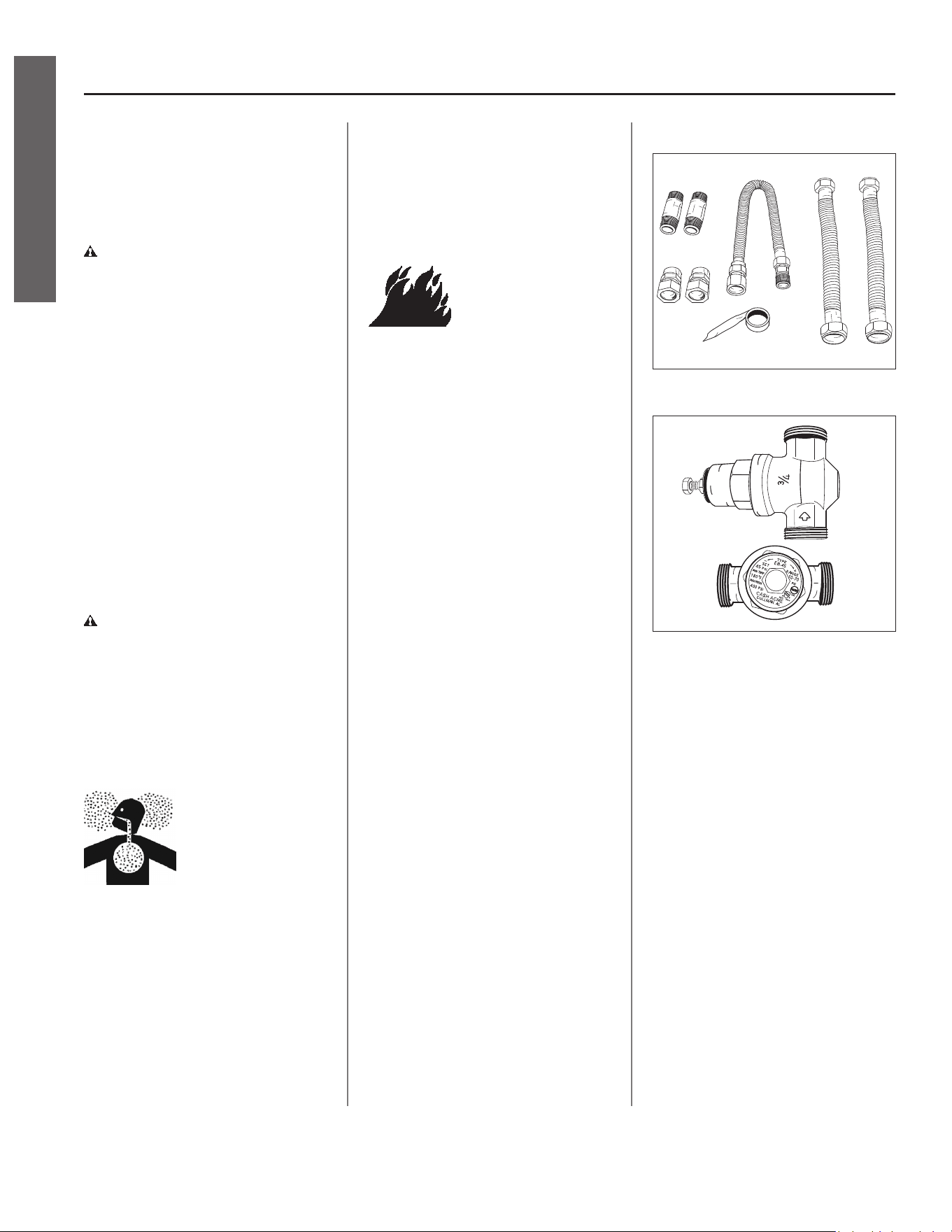
Installaon Accessories
Figure 1 - Gas Water Heater Hook-Up Kit
Figure 2 - Install a Pressure Reducing Valve set
to 50 to 60 psi.
SAFETY
IMPORTANT SAFETY INFORMATION
Residenal Gas Water Heater Use and Care Guide • 7
GETTING STARTED
GETTING STARTED
1
Review all of the instrucons
before you begin work.
Improper installaon can
damage the water heater, your home
and other property, and can present
risks of serious injury or death.
2
This water heater is a direct
vented water heater which
takes its combuson air from
the outside of the structure and
exhausts all products of combuson
to the outside of the structure.
This water heater must be installed
according to all local and state codes
or, in the absence of local and state
codes, the “Naonal Fuel Gas Code”,
ANSI Z223.1 (NFPA 54)-current
edion. This is available from the
following:
CSA America, Inc.
8501 East Pleasant Valley Road
Cleveland, OH 44131
Naonal Fire Protecon Associaon
1 Baerymarch Park
Quincy, MA 02269
Check with local code ocials about
codes governing this installaon.
Have your installaon inspected by a
code ocial to ensure the installaon
meets all local codes.
NOTICE: If you lack the necessary
skills required to properly install this
water heater, or you have diculty
following the instrucons, you should
not proceed but have a qualied
person perform the installaon of this
water heater.
Massachuses code requires this
water heater to be installed in
accordance with Massachuses
248-CMR 2.00 and 248-CMR 5.00:
State Plumbing Code. Other local
and state authories may have
similar requirements or other codes
applicable to the installaon of this
water heater.
3
Before you start, be sure you
have the following tools and
supplies:
• Plumbing tools and supplies appro-
priate for the type of water pipes in
your home.
• Thread sealant tape or pipe joint
compound approved for potable
water.
• For homes with copper pipes, you
may purchase a Gas Water Heater
Hook-Up Kit (available at your local
plumbing supplier) with compres-
sion ngs that do not require
soldering. This kit includes two 12”
ex water lines, an 18” exible gas
line, two nipples, and thread sealant
tape.
• For homes with plasc pipe, use
threaded connectors suitable for the
specic type of plasc pipe used:
CPVC or PEX (cross-linked polyeth-
ylene). Do not use PVC pipe.
• Non-corrosive gas leak detecon
soluon made from hand dishwash-
ing soap mixed with water (1 part
soap to 15 parts water) or children’s
soap bubbles and a small, so-bris-
tled brush.
• An appliance dolly or hand truck to
move the water heater.
Recommended Accessories
• A metal drain pan
• Automac water leak detecon and
shut-o device
• Pressure Reducing Valve
• Thermal Expansion Tank
• Thermostac Mixing Valves at each
point-of-use
• Fuel gas and carbon monoxide
detector
Combuson and
Venlaon Air Supply
Before installing the water heater, you
must determine the amount of air
needed to supply this water heater
and any other gas appliances in the
same area and provide adequate air
for combuson and venlaon.
WARNING! This gas water heater
requires and adequate source
of clean air for combuson and
venlaon. Without sucient air,
your water heater will have frequent
pilot outages and may emit excessive
and abnormal amounts of carbon
monoxide.
Before beginning:
For safe operaon an adequate supply
of fresh, uncontaminated air must be
provided for combuson.
This gas-red water heater is a direct
vent model. It connects directly to
the outside of the building through
the vent terminaon hood. The hood
operates as both the combuson air
intake and the heater exhaust port
(see Figure 4).
All combuson air is obtained from
outside the building through this
hood. Ensure the area around the
terminaon hood is always kept clear
and that the air supply is not exposed
to contaminaon or ammable
vapors.
8 • Residenal Gas Water Heater Use and Care Guide
Venng
WARNING! Carbon Monoxide
Hazard. This water heater must
be supplied with adequate air and
vented outdoors. The vent system
must be installed by a qualied
person. Examples of a qualied
person include gas technicians,
authorized gas company personnel,
and authorized service technicians.
Failure to properly vent the water
heater can result in severe injury
or death from carbon monoxide
poisoning.
The vent system must be installed
according to local and state codes, or
in the absence of local or state codes,
the “Naonal Fuel Gas Code”, ANSI
Z223.1 (NFPA 54)-current edion. Do
not common vent this water heater
with any power vented appliance. Do
not use a vent damper anywhere in
the vent system of this water heater.
To reduce the risk of carbon monoxide
poisoning, install a fuel gas and
carbon monoxide detector. Install and
maintain the detector in accordance
with the manufacturer’s instrucons
and local codes.
Installing a New Vent System
This direct vent water heater uses a
sealed venng system to supply fresh
combuson air to the heater and to
exhaust the products of combuson
(ue gases) to the outdoors The
venng is a “pipe in a pipe” system.
The inner (3”) piping carries out the
exhaust ue gases while the outer (6”)
piping carries in fresh combuson air.
The corrugated end of the vent piping
connects to the top of the water
heater and the opposite end connects
to the vent terminaon hood which
will be mounted on the exterior wall
(see Figure 4). Figure 4 shows the
hot exhaust gas exit and the locaon
of the combuson air intake. Figure
7 through Figure 13 show how to
assemble and connect the venng
system.
Figure 14 through Figure 18 show
various installaon opons.
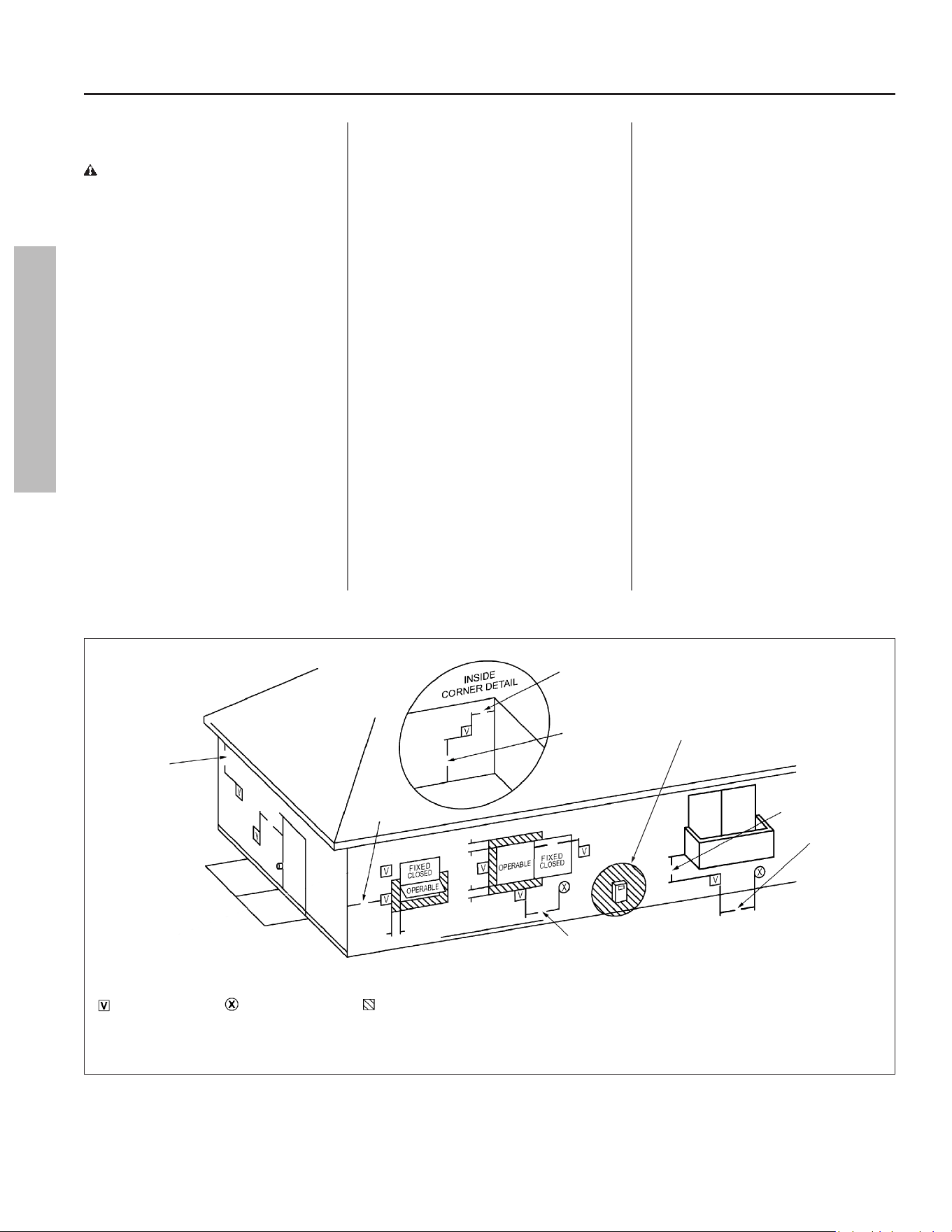
Vent Terminal Clearances
The vent system must terminate so
that proper clearances are maintained
as cited in local codes or the current
edion of the “Naonal Fuel Gas
Code”, ANSI Z223.1/NFPA 54 as
follows:
GETTING STARTED
GETTING STARTED
**Minimum 12 in.
Minimum 12 in.
above grade or
anticipated snow
level
Minimum 12 in.
under veranda, porch,
deck or balcony
(see footnote 1)
Minimum
3 ft.
above if within
10 ft.
horizontally to
a mechanical air
supply inlet
Minimum 9 in. to a non mechanical air supply inlet
into building or combustion air inlet to another appliance
Minimum 12 in.
from soffit
*Minimum 9 in. to
a window or door
that may be opened
**Minimum
18 in.
from outside
corner
1. Permitted only if veranda, porch, deck or balcony is fully opened on a minimum of two sides beneath the floor.
2. A vent shall not terminate above a sidewalk or paved driveway that is located between two single family dwellings and serves both dwellings.
AREA WHERE TERMINAL IS NOT PERMITTED
VENT TERMINAL AIR SUPPLY INLET
Minimum
3 ft.
clearance to a
service regulator
vent outlet
** Or as required by local authorities.
Figure 3 - Vent Terminaon Hood
Residenal Gas Water Heater Use and Care Guide • 9
GETTING STARTED
GETTING STARTED
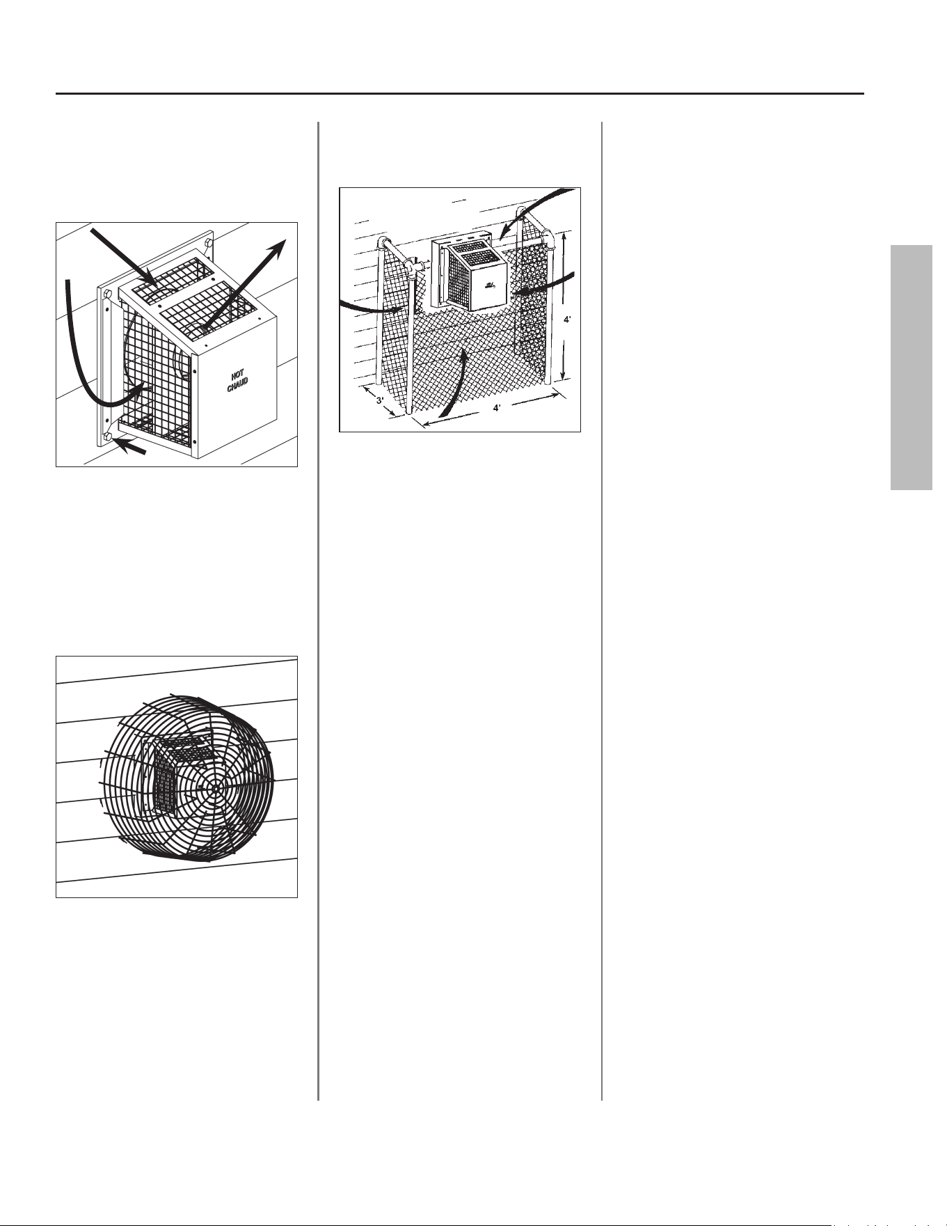
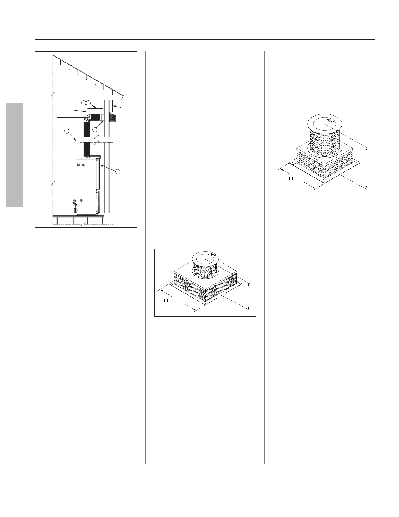
DV Terminaon Hood
When the heater is in operaon, the
vent terminaon hood will be hot (see
Figure 4).
HOT
EXHAUST
GAS OUT
FRESH
COMBUSTION
AIR IN
SCREW
Figure 4 - Vent Terminaon Hood
DV Terminaon Safety Cover
A Safety cover (see Figure 5) is
available to prevent accidental contact
with the vent terminal. Contact your
Customer Service Department for
ordering informaon.
Figure 5 - Safety Cover
Alternavely, a wire mesh or louvered
fencing guard can be built around the
terminaon as shown in Figure 6.
NOT TO BE USED AS
A STORAGE AREA
Figure 6 - Fencing Guard/Safety Cover
Vent Connecon
Aer the locaon for the vent
terminal has been selected as outlined
in Figure 3 and Figure 4, use the
following illustraons for installaon:
Locang Clearance Hole for Vent
Cut a clearance hole, approximately
7”in diameter, through the exterior
wall for the vent assembly. The
recommended height is 64” for 40
gallon models or 73” for 50 gallon
models, as measured from the hole
center to boom of water heater.
Where the wall is combusble and
the wall thickness is over 14”, a 1”
clearance to combusble surfaces
around the vent terminal is needed.
The rst 14” is zero clearance (see
Figure 9 on page 10).
Standard Vent Arrangement
* If the horizontal length of the
venng is less than 30” the restricter
plate must be installed (see Figure 10,
Figure 16 through Figure 18).
• Do not use the restricter plate in an
oset installaon (see Figure 14).
• Do not use the restricter plate if the
horizontal length of the venng is
greater than 30”.
• Do not use the restricter plate for
installaons where elevaon is at or
exceeds 5,400 feet.
NOTICE: The length of “unstretched”
corrugated tube could cause the
length of the vent run to exceed the
minimum. In this case cut o a piece
of the corrugated tube to achieve the
17” minimum vent length.
10 • Residenal Gas Water Heater Use and Care Guide
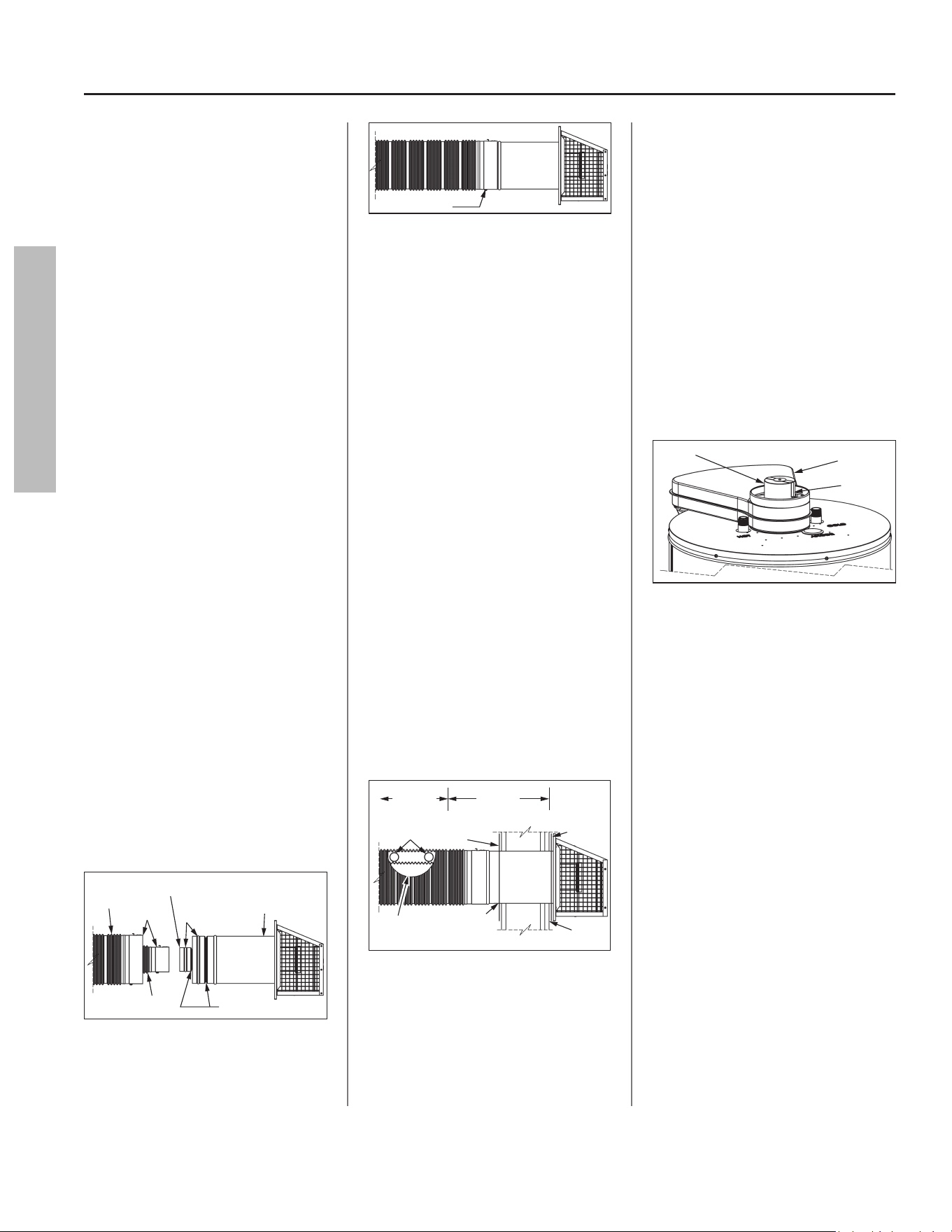
Vent Assembly
The vent piping and the vent
terminaon hood are to be connected
as shown in Figure 7. Maintain
vent clearances to combusbles
as shown in Figure 9. Depending
on your access to where the vent
terminaon passes through the wall,
you may wish to connect the piping
and vent terminaon hood together
rst. Inside the vent piping there are
springs that hold the two corrugated
pipes in posion. When the pipes
are stretched to the required length,
the springs will remain properly
spaced. To connect the vent piping
to the vent terminaon hood, rst
slide the inner (3”) corrugated pipe
over the inner vent terminaon pipe.
Connue this acon unl the locking
clip on the corrugated pipe snaps into
posion in the corresponding groove
(see Figure 7). Secure corrugated
pipe with screw (supplied) inserted
through hole opposite the locking clip.
Repeat this process with the outer
(6”) corrugated pipe and lock it into
posion on the outer pipe on the vent
terminaon (see Figure 7). Secure
corrugated pipe with screw (supplied)
inserted through hole opposite the
locking clip.
NOTICE: To reduce the fricon
between the corrugated pipe and
the O-rings, it is recommended to
dampen the O-rings with water. The
completed connecon is shown in
Figure 8.
Outer
Corrugated
Pipe
Locking
Clip
Inner Vent Termination
Pipe
Outer Vent
Termination Pipe
Inner
Corrugated Pipe
Locking Clip
Groove
O-Ring
Figure 7 - Vent Piping
Screw
Figure 8 - Completed Vent Connecon
Securing Vent Terminaon
Assembly to the Exterior Wall
Some models are supplied with trim
plates which may be used to cover
the holes in the wall (see “Completed
Installaon” on page 2 and
Figure 9). Slide one trim plate (if
supplied) over the outer corrugated
tube, then insert the outer corrugated
tube through the clearance hole from
exterior wall. Secure the trim plate to
the exterior wall, then secure the vent
terminal to the exterior wall with 4
screw anchors (included) appropriate
for the type of wall construcon.
Caulk the juncon of the vent terminal
base plate and the exterior wall with
exterior type sealant (not included).
Slide the trim plate (inside) over the
outer corrugated tube and fasten the
trim plate to the interior wall. Caulk
the juncon of the outer corrugated
tube and the trim plate (inside) with
suitable sealant. The vent terminaon
hood aaches to the vent piping as
shown in Figure 9.
Spring
Trim Plate
(Inside)
Apply
Sealant
Cutaway to
Show Spring
Placement
Apply
Sealant
Trim Plate
(Outside)
1”
Clearance
14” Zero
Clearance
Figure 9 - Trim Plate Install
Vent Restricter Plate
The vent restricter plate (see Figure 10)
is required for short horizontal runs on
low vent installaons (Figure 16) and
high vent installaons (Figure 18).
For short horizontal vent runs (see
Figure 17) place the restricter plate
over the ue tube reducer before
connecng the inner corrugated tube
to the ue tube reducer. DO NOT use
the restricter plate if the horizontal run
is greater than 30”.
For high vercal runs use the restricter
plate only when the vercal run of the
venng above the heater is greater
than 48” (see Figure 18).
Do not use the restricter plate for
short horizontal runs or high vent
installaons where elevaon exceeds
5,400 feet.
Flue Tube
Reducer
Upper Air
Inlet Box
Restricter
Plate
Figure 10 - Restricter Plate
Uncompressing the Corrugated
Tubing
• Pull the inner corrugated tube
towards the water heater and leave
some length over the water heater’s
center for bending (see Figure 11).
• Pull the outer corrugated tube
toward the water heater and leave it
2” shorter than the inner corrugated
tube.
• Make sure there are two springs
evenly spaced at the bend in the
tube.
• Use metal hangers spaced a maxi-
mum of 36” apart to keep venng
level or with a slope upward from the
heater to terminal. It is recommend-
ed to add vibraon isolaon between
the venng and hangers to prevent
vibraon and noise from spreading
to the rest of the building.
GETTING STARTED
GETTING STARTED
Residenal Gas Water Heater Use and Care Guide • 11
GETTING STARTED
GETTING STARTED
Flue Tube
Reducer
Inner
Corrugated
Pipe
Apply
Silicone
Flue Tube
Reducer
Restricter
Plate
Figure 11 - Uncompressing the Corrugated
Tubing
Vent Connecon to the Water
Heater
Bend both the corrugated pipes
toward the ue connecon on the
water heater. Pull and connect the
inner corrugated pipe to the water
heater’s ue tube reducer with hi-
temp red silicone (included) and gear
clamp. Make sure this connecon is
ght and leak proof (see Figure 12).
*The sealant between the inner
corrugated pipe and water heater’s
ue tube reducer must be hi-temp red
silicone or other material suitable for
600°F connuous service.
NOTICE: If you are using the vent
restricter plate, the inner vent pipe is
to go over the side legs and down the
stops.
Smooth
Easy Curve
Restricter
Plate Stop
Cutaway to
Show Details
Gear Clamp
Figure 12 - Vent Connecon to the Water
Heater
Apply hi-temp red silicone (included)
around the collar on air manifold box.
Pull the outer corrugated pipe all the
way on to collar and secure with the
gear clamp. Pull the free end of the
corrugated pipe past the gear clamp
and secure with one sheet metal
screw (see Figure 13).
Smooth
Easy Curve
Apply silicone
to Airbox before
attaching pipe
Secure with
a sheetmetal
screw
Gear Clamp
Figure 13 - Apply Silicone to the Venng
Oset Vent Arrangement
Where a straight vent arrangement is
impossible, a horizontal 90° maximum
bend can be made. Use the water
heater casing outer diameter as a
template to form the corrugated tube.
Smooth
Easy Curve
90°
Maximum
Bend
Figure 14 - Venng Alignment (Top View)
Figure 15 - Bad Venng Conguraons
NOTICE: To ensure good exhaust gas
ow, bend vent piping using a smooth,
easy curve as shown in Figure 12
through Figure 14. Do not use reverse
or compound curves as shown in
Figure 15.
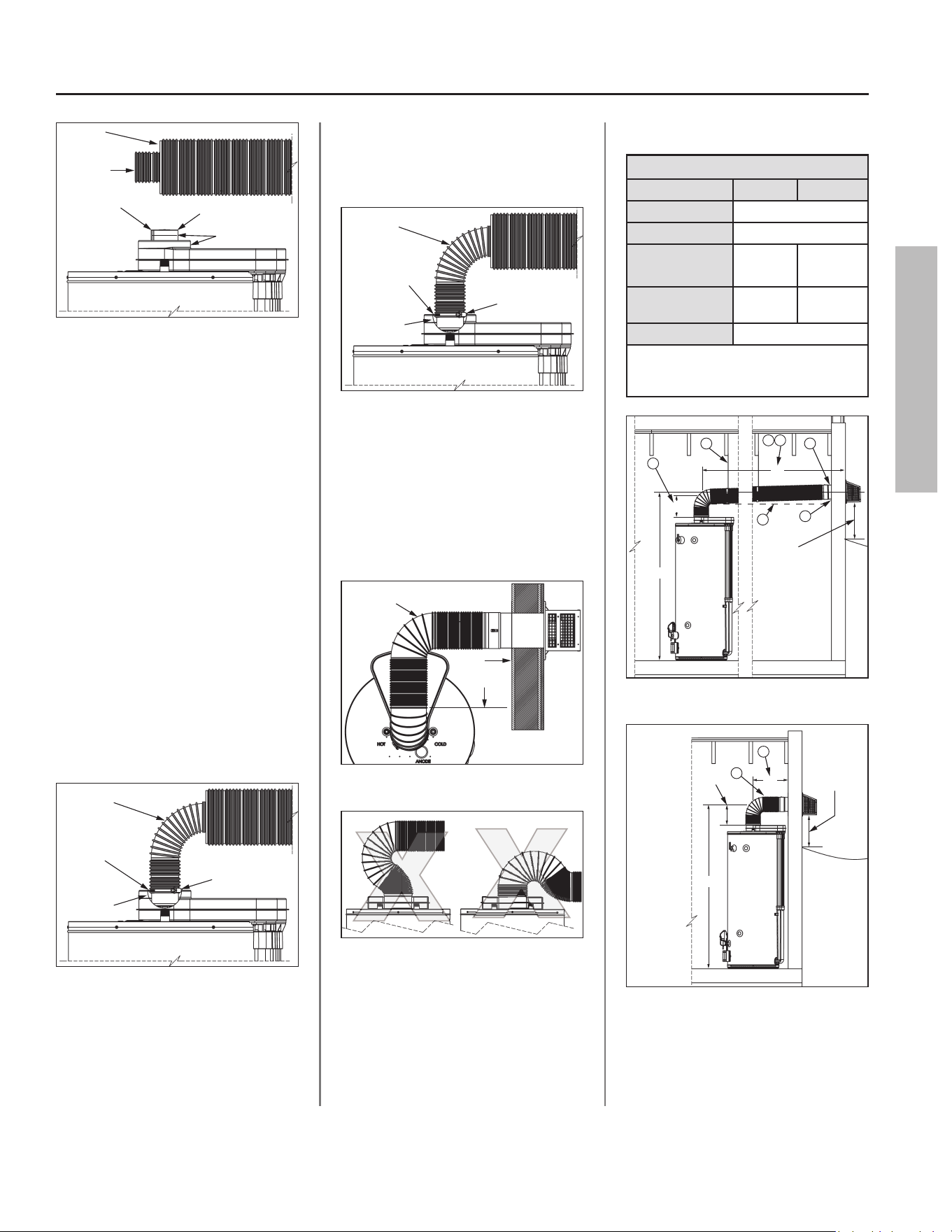
Use Table 2 with Figures 16-18.
Table: 2
DIM. 4036 5038
A 80” MAX.
B 9” MIN.
C
(RECOMMENDED)
63.63” 73.00”
C
(MINIMUM)
60.75 69.50
D 14.25” MIN.
NOTICE: Dimension “C” is the height above
to oor to the center of the terminaon hole
through the exterior wall.
Above
anticipated
snow level
or 12” above
grade.
1
9
1
5
6
7
8
C
A
B
Low Vent Installation
Figure 16 - Low Venng Installaon
Above
anticipated
snow level
or 12” above
grade.
9
4
C
D
Medium Vent Installation
9”
Figure 17 - Medium Venng Terminaon
12 • Residenal Gas Water Heater Use and Care Guide
12” Min.
Below
Soffit
72”
Max.
High Vent Installation
17”
Min.
6
1 5
1
2
Figure 18 - High Venng Terminaon
NOTES: (applies to Figure 16 through
Figure 18)
1. In any installaon the total of
dimension “A” plus dimension “B”
must not exceed 89”.
2. This heater can be installed with
0” clearance to a wall.
3. Minimum vent pipe clearance to
combusbles is 1” (see Figure 9).
4. Minimum distance from center of
heater to wall is 14.25”.
5. Dimension “A” includes wall
thickness.
6. Hole diameter in wall is 7”.
7. Venng must slope up away from
the heater a minimum of 0.25”
per foot of length to prevent
condensaon from collecng and
to provide sucient dra.
8. Distance above horizontal at full
extension is 2”.
9. Use support stays to hold the
venng to avoid sags or valleys.
Replacing a Water
Heater Using the
Exisng Vent System
Read the “Installing a New Vent
System” secon of this manual
and make sure your vent system
is properly installed. Inspect the
exisng vent system for obstrucons,
corrosion, and proper installaon.
Repair or replace if necessary. The
exisng vent system must be UL listed
and installed according to the vent
manufacturer’s instrucons and the
terms of its lisng. Do not use other
materials such as dryer vent hose.
See Applicaon A and B to determine
if your new water heater can be
retroed to an exisng vent
terminaon hood:
Vent Terminaon Hood
(Applicaon A)
11-13/16"
7"
Figure 19 - American Vent Terminaon Hood (A)
A current American DV water heater
vent terminaon includes 3 inch inner
piping to carry out the exhaust ue
gases and 5 inch outer piping to carry
in fresh combuson air.
If replacing a current American DV
water heater, a duct reducer and
union adapter must be installed to
connect the exisng vent terminaon
hood to new inner and outer piping.
Use kit number 100366535.
IMPORTANT: A weather shroud
is provided in this kit and must
be installed over the exisng vent
terminaon hood to ensure adequate
protecon from wind and other
weather related hazards. Failure to do
so may result in pilot outages at the
water heater.
Vent Terminaon Hood
(Applicaon B)
8"
8-1/2"
Figure 20 - Bradford White Vent Terminaon
Hood (B)
A Bradford White® DV water heater
vent terminaon includes 3 inch inner
piping to carry out the exhaust ue
gases and 5 inch outer piping to carry
in fresh combuson air.
If replacing a Bradford White DV
water heater, a duct reducer and
union adapter must be installed to
connect the exisng vent terminaon
hood to new inner and outer piping.
Use kit number 100366536.
If you are not sure the exisng vent
terminaon hood is compable
with your new water heater, call our
Technical Assistance Hotline which is
listed on the water heater’s warranty
sheet.
GETTING STARTED
GETTING STARTED
Residenal Gas Water Heater Use and Care Guide • 13
GETTING STARTED
GETTING STARTED
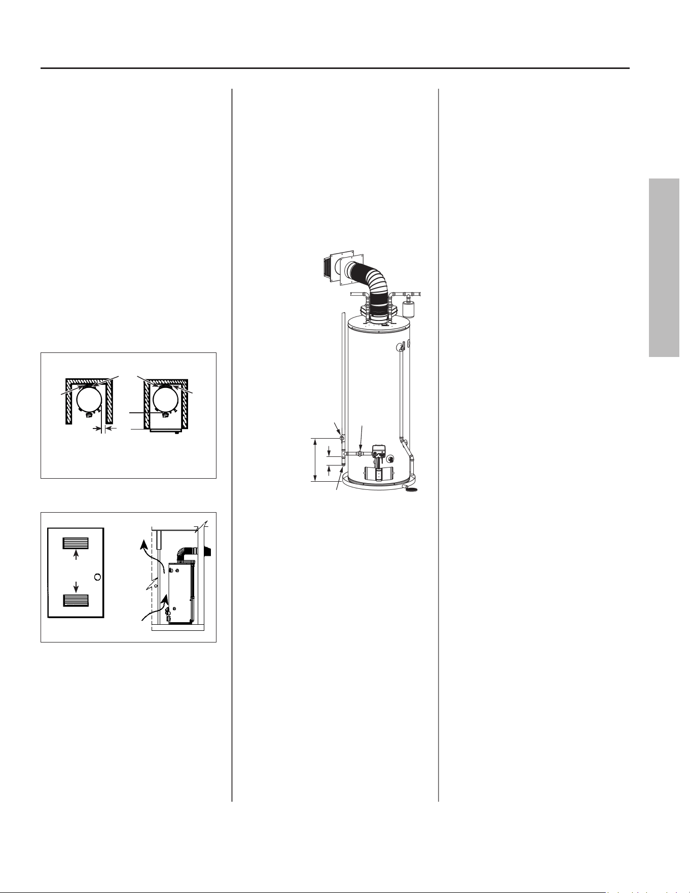
Conned Space
Installaons
This water heater connects to the vent
terminaon hood using the sealed air
intake and exhaust piping.
During operaon this piping
can become hot, especially in
areas experiencing high ambient
temperatures.
When installed in a conned space
such as a closet, it is recommended
that the conned space be venlated
to minimize the buildup of heat
around the water heater. Figure 21
and Figure 22 show examples of
venlang a conned space.
TOP VIEW
OF CLOSET
WITHOUT DOOR
AIR
INTAKE*
TOP VIEW OF
CLOSET WITH
DOOR
0” MIN.
0”
MIN.
5.5” MIN.
* DO NOT BLOCK OR RESTRICT IN
ANY MANNER, THE AIR INTAKES AT
THE BACK OF THE WATER HEATER.
0”
MIN.
Figure 21 - Conned Space Clearances
ROOM
AIR FLOW
ROOM AIR
FLOW
FRONT VIEW
OF DOOR
VENTILATION
AIR
OPENING
Figure 22 - Conned Space Venlaon
Gas Piping
Gas piping must be installed according
to local and state codes or, in the
absence of local and state codes, the
“Naonal Fuel Gas Code”, ANSI Z223.1
(NFPA 54)-current edion.
NOTICE: When installing gas piping,
apply pipe joint compound or thread
sealant tape approved for fuel gases.
Ground
Joint
Union
Manual Gas
Shut-off
3” Min.
Check with
local utility for
minimum height
Sediment Trap
Figure 23 - Gas Piping
1. Install a readily accessible manual
shut-o valve in the gas supply
line as recommended by the local
ulity. Know the locaon of this
valve and how to turn o the gas
to this unit.
2. Install a Sediment Trap as shown
in the Gas Piping gure below.
The Sediment Trap must be no
less than three inches long for
the accumulaon of dirt, foreign
material, and water droplets.
3. Install a ground joint union be-
tween the gas control valve and
the manual gas shut-o valve.
This is to allow easy removal of
the gas control valve. NOTICE: a
hard line connecon is shown in
Figure 23 (a exible gas line con-
necon may also be used).
4. Turn the gas supply on and check
for leaks. Use a small, so-bristled
brush to apply a hand dishwash-
ing soap and water mixture (1
part soap to 15 parts water) or
children’s soap bubbles to all con-
necon points of the gas piping.
Saturate all the connecons and
check for gas leaks (which will
appear as small bubbles). If any
leaks are detected, ghten the
appropriate connecon(s) and
re-check.
Gas Pressure
NOTICE: When tesng gas pipes with
a test pressure of more than ½ psi (3.5
kPa), disconnect the gas line at the
manual shut-o valve and cap the gas
line. Do not subject the water heater’s
gas control valve or manual shut-o
valve to more than ½ psi (3.5 kPa)
pressure for any reason. If you are
pressure tesng the gas line with test
pressure of ½ psi (3.5 kPa) or less, you
may isolate the water heater from the
gas line by closing the manual shut-o
valve.
14 • Residenal Gas Water Heater Use and Care Guide
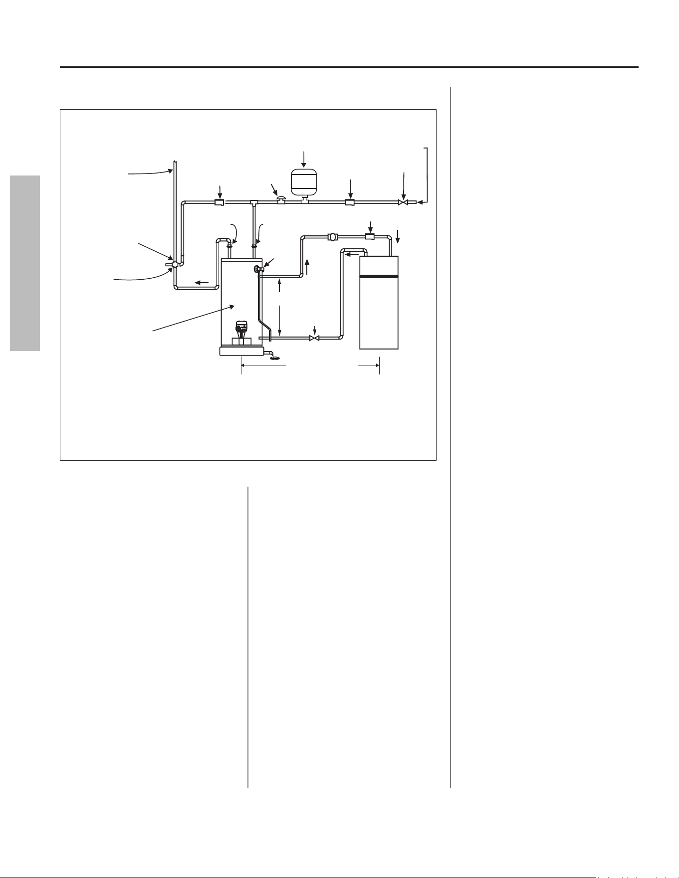
Space Heang
IN
REMOVE
A
MU
ST BE VERTICAL TO
IR BUBBLES
E
OUT
COIL
AIR
HANDLER
TO
AIR
HANDLER
SHUT-OFF
VALVE
*
EXPANSION TANK
VACUUM
RELIEF
VALVE
COLD WATER INLET
VA
FLOW CONTROL
LV
PUMP
*
SHUT-OFF
CHECK VALVE
†
(1/8” HOLE
DRILLED IN CLAPPER)
VALVE
CHECK
VALVE
†
TEMP/
PRESSURE
RELIEF
VALVE
TEMPERED WATER
TO FIXTURES
(MUST MEET TEMPS LISTED
IN MASS. CODE 248 CMR
†
)
MIXING VALVE
(MUST BE INSTALLED BELOW
TOP OF WATER HEATER
AS PER MANUFACTURER’S
RECOMMENDATIONS)
UNION
UNION
HOT
WATER
OUT
*
MASSACHUSETTS INSTALLATION REQUIREMENTS:
1.) CONNECT ELECTRONICALLY-CONTROLLED TIMER TO AN ALL-BRONZE PUMP. PUMP MUST ACTIVATE EVERY 6 HOURS
FOR 60 SECONDS. TURN PUMP TIMER OFF BEFORE CLOSING PIPING LOOP SHUT-OFF VALVE.
2.) ALL WATER PIPING MUST BE INSTALLED AND INSULATED IN ACCORDANCE WITH MASSACHUSETTS CODE (248 CMR
& 780 CMR).
3.) PIPING LOOP BETWEEN WATER HEATER AND AIR HANDLER MUST BE INSTALLED IN COMPLIANCE WITH 248 CMR.
† REQUIRED FOR MASSACHUSETTS.
‡ PIPING FROM THE TOP OF THE WATER HEATER WITH TEES IS ACCEPTABLE.
WATER HEATER ACCEPTED
BY THE BOARD FOR
INSTALLATION IN
MASSACHUSETTS.
†
TYPICAL MIXING VALVE INSTALLATION
COMBINATION SPACE HEATING / POTABLE WATER HEATING SYSTEM
SEE
NOTE ‡
100’-0” MAXIMUM DISTANCE
FROM WATER HEATER
TO FAN COIL AND BACK
(DEVELOPED LENGTH) NOT
INCLUDING COIL IN HEATING UNIT.
†
Figure 24 - Combuson Space Heang and Potable Water (Typical Installaon)
Some water heater models
are equipped with inlet/outlet
connecons for use with space
heang applicaons. If this water
heater is to be used to supply both
space heang and domesc potable
(drinking) water, the instrucons
listed below must be followed:
• This water heater is suitable for
combinaon water (potable) heang
and space heang and not suitable
for space heang applicaons only.
• Be sure to follow the manual(s)
shipped with the air handler system.
• This water heater is not to be used
as a replacement for an exisng
boiler installaon.
• Do not use with piping that has
been treated with chromates, boiler
seal or other chemicals and do not
add any chemicals to the water
heang piping.
• If the space heang system requires
water temperatures in excess of
120°F, install a Thermostac Mixing
Valve in the domesc (potable) hot
water supply at each point-of-use to
limit the risk of scald injury. Install
the mixing valve per its manufactur-
er’s instrucons.
• Pumps, valves, piping, and ngs
must be compable with potable
water.
• A properly installed ow control
valve is required to prevent ther-
mosiphoning. Thermosiphoning is
the result of a connuous ow of
water through the air handler circuit
during the o cycle.
• The domesc hot water line from
the water heater should be vercal
past any mixing valve or supply line
to the air handler to remove air bub-
bles from the system. Otherwise,
these bubbles will be trapped in
the air handler heat exchanger coil,
reducing eciency.
• Do not connect the water heater to
any system or components previ-
ously used with non-potable water
heang appliances when used to
supply potable water.
GETTING STARTED
GETTING STARTED
Residenal Gas Water Heater Use and Care Guide • 15
INSTALLATION
INSTALLATION
Step: 1
✓
Verify that Your
Home is Equipped
and Up-To-Date
for Proper Operaon
Installing a new water heater is the
perfect me to examine your home’s
plumbing system and make sure
the system is up to current code
standards. There have likely been
plumbing code changes since the
old water heater was installed. We
recommend installing the following
accessories and any other needed
changes to bring your home up to the
latest code requirements. Updang
your plumbing system can help extend
the life of your water heater, avoid
damage to your home and property,
and reduce the risk of serious injuries
or death. Inspect your home and
install any devices you need to comply
with current codes and assure that
your new water heater performs at its
best. Check with your local plumbing
ocial for more informaon.
✓
Water Pressure
Most codes allow a maximum
incoming water pressure of 80 psi
(we recommend a working pressure
no higher than 50-60 psi). Check
your home’s water pressure gauge
and adjust if necessary. High water
pressure can damage the water
heater, piping, and other appliances.
HOW: Purchase an inexpensive
water pressure gauge from your local
plumbing supplier. Connect the water
pressure gauge to an outside faucet
and measure the maximum water
pressure experienced throughout
a 24-hour period (highest water
pressures oen occur at night).
140
20
40
60
80
100
120
160
180
200
psi
AVOID FREEZING
Figure 25 - Use a Water Pressure Gauge to make
sure your home’s water pressure is not too high.
To adjust your home’s water pressure:
Locate your home’s Pressure Reducing
Valve (PRV) on the main incoming
(cold) water supply line and adjust the
water pressure control to between
50 and 60 psi. If your home does not
have a Pressure Reducing Valve, install
a PRV on the home’s main water
supply line and set it to between 50
and 60 psi. Pressure Reducing Valves
are available at your local plumbing
supplier.
BACKGROUND: Over the years,
many ulies have increased water
supply pressures so they can serve
more homes. In some homes today,
pressures can exceed 100 psi. High
water pressures can damage water
heaters, causing premature leaks.
If you have replaced toilet valves,
had a water leak, or had to repair
appliances connected to the plumbing
system, pay parcular aenon to
your home’s water pressure. When
purchasing a PRV, make sure the PRV
has a built-in bypass.
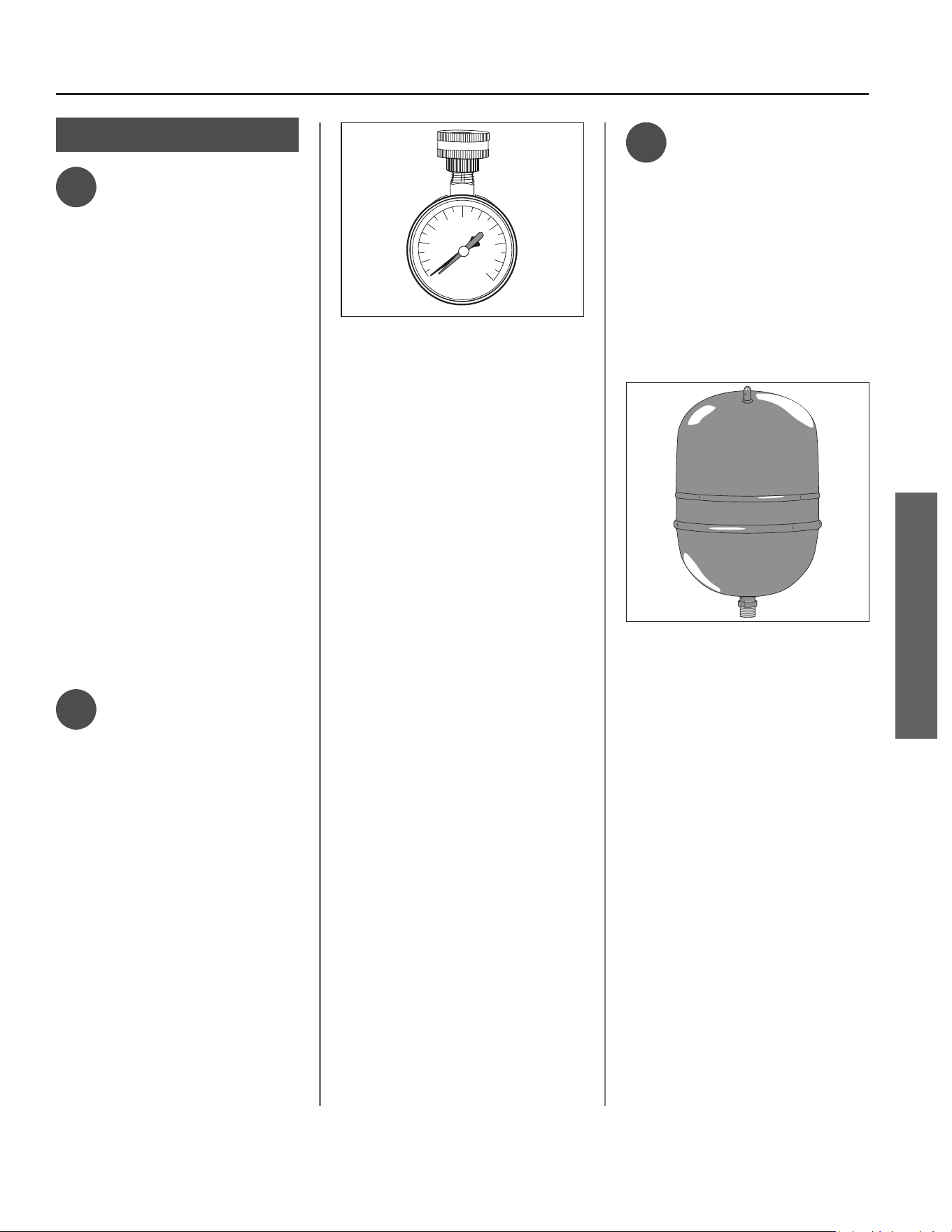
✓
Water Pressure
Increase Caused
by Thermal
Expansion
Verify that you have a properly
sized Thermal Expansion Tank. We
recommend installing an expansion
tank if your home does not have one.
Plumbing codes require a properly
pressurized, properly sized Thermal
Expansion Tank in almost all homes.
Figure 26 - A Thermal Expansion Tank helps
protect the home’s plumbing system from
pressure spikes.
HOW: Connect the Thermal Expansion
Tank (available at your local plumbing
supplier) to the cold water supply
line near the water heater. The
expansion tank contains a bladder and
an air charge. To work properly, the
Thermal Expansion Tank must be sized
according to the water heater’s tank
capacity and pressurized to match
the home’s incoming water pressure.
Refer to the instrucons provided
with the Thermal Expansion Tank for
installaon details.
BACKGROUND: Water expands when
heated, and the increased volume
of water must have a place to go, or
thermal expansion will cause large
increases in water pressure (despite
the use of a Pressure Reducing Valve
in the home’s main water supply
line). The Safe Drinking Water Act of
16 • Residenal Gas Water Heater Use and Care Guide
1974 requires the use of backow
preventers and check valves to restrict
water from your home reentering
the public water system. Backow
preventers are oen installed in
water meters and may not be readily
visible. As a result, most all plumbing
systems today are now “closed,” and
almost all homes now need a Thermal
Expansion Tank.
A Thermal Expansion Tank is a
praccal and inexpensive way to help
avoid damage to the water heater,
washing machine, dishwasher, ice
maker, and even toilet valves. If
your toilet occasionally runs for no
apparent reason (usually briey at
night), that may be due to thermal
expansion increasing the water
pressure temporarily.
✓
Water Pipe and
Tank Leaks
Drain
Drain Pan
Drain Pan
Discharge Pipe
Figure 27 - A metal drain pan piped to an
adequate drain can help protect ooring from
leaks and drips.
Leaks from plumbing pipes or from
the water heater itself can damage
property and could cause a re risk.
• Install an automac leak detecon
and shut-o device (available at
your local plumbing supplier). These
devices can detect water leaks and
can shut o the water heater’s wa-
ter supply if a leak occurs.
• Install a metal drain pan (available at
your local plumbing supplier) under
the water heater to catch conden-
saon or leaks from the piping
connecons or tank. Most codes
require, and we recommend, install-
ing the water heater in a metal drain
pan that is piped to an adequate
drain. The drain pan must be at least
two inches wider than the diameter
of the water heater. Install the drain
pan so the water level would be
limited to a maximum depth of 1-¾”.
The pan must not restrict air ow to
the burner.
✓
Water Tempera-
ture Regulaon
Install Thermostac Mixing Valves
to regulate the temperature of the
water supplied to each point-of-use
(for example, kitchen sink, bathroom
sink, bath, shower). Install and adjust
the mixing valve according to its
manufacturer’s instrucons.
WARNING! Even if the water
heater’s thermostat is set to a
relavely low temperature, hot water
can scald. Install Thermostac Mixing
Valves at each point-of-use to reduce
the risk of scalding (see Table 1).
MIX
Figure 28 - Thermostac Mixing Valves installed
at each point-of-use can help avoid scalding.
BACKGROUND: A Thermostac Mixing
Valve, installed at each point-of-use,
mixes hot water from the water
heater with cold water to more
precisely regulate the temperature of
hot water supplied to xtures. If you
are not sure if your plumbing system
is equipped with properly installed
and adjusted Thermostac Mixing
Valves at each point where hot water
is used, contact a qualied person.
INSTALLATION
INSTALLATION
Residenal Gas Water Heater Use and Care Guide • 17
INSTALLATION
INSTALLATION
Step: 2
Verify that the Locaon
is Appropriate
WARNING! Do not store or use
ammable materials, vapors, or
liquids in the same locaon where
this water heater is installed.
Before installing your water heater,
ensure that it will be located:
• Indoors in an area with adequate air
supply.
• In an area that will not freeze.
• In a locaon as close to a wall as
praccable and as centralized with
the water piping system as possible.
• In a metal drain pan piped to an ad-
equate oor drain or external to the
building (Figure 36 on page 19).
• In an area with adequate space
(clearances) for periodic servicing.
There must be a minimum of 5-1/2
inches of front clearance, however,
24 inches of clearance is recom-
mended.
• In an area that allows minimum
clearances between the water
heater and combusbles. Minimum
clearances are 0 inches at the sides
and rear, 5-1/2 inches from the front
and 12 inches from the top. Mini-
mum clearances from vent piping
to combusbles is 1 inch except as
noted in Figure 9.
• On a oor that can support the
weight of a full water heater.
You will also want to follow these
guidelines while considering an
appropriate locaon:
• Do not install near air-moving devic-
es such as exhaust fans, venlaon
systems, or clothes dryers.
• Do not obtain venlang air for the
furnace/air handler from the same
space as the water heater. Ensure
that any return air ducts near the
water heater are sealed.
• Do not install in a bathroom,
bedroom, or any occupied room
normally kept closed.
• If the water heater is installed
directly on carpeng, it shall be
installed on a metal or wood panel
extending beyond the full width
and depth of the water heater by at
least 3 inches in any direcon. If the
water heater is installed in an alcove
or closet, the enre oor shall be
covered by the aforestated panel.
• If your area is prone to earthquakes,
use special straps as required by
local building codes.
NOTICE: The state of California
requires bracing, anchoring, or
strapping the water heater to avoid its
moving during an earthquake. Contact
local ulies for code requirements in
your area, visit hp://www.dsa.dgs.
ca.gov, or call 1-916-445-8100 and
request instrucons. Other locaons
may have similar requirements. Check
with your local and state authories.
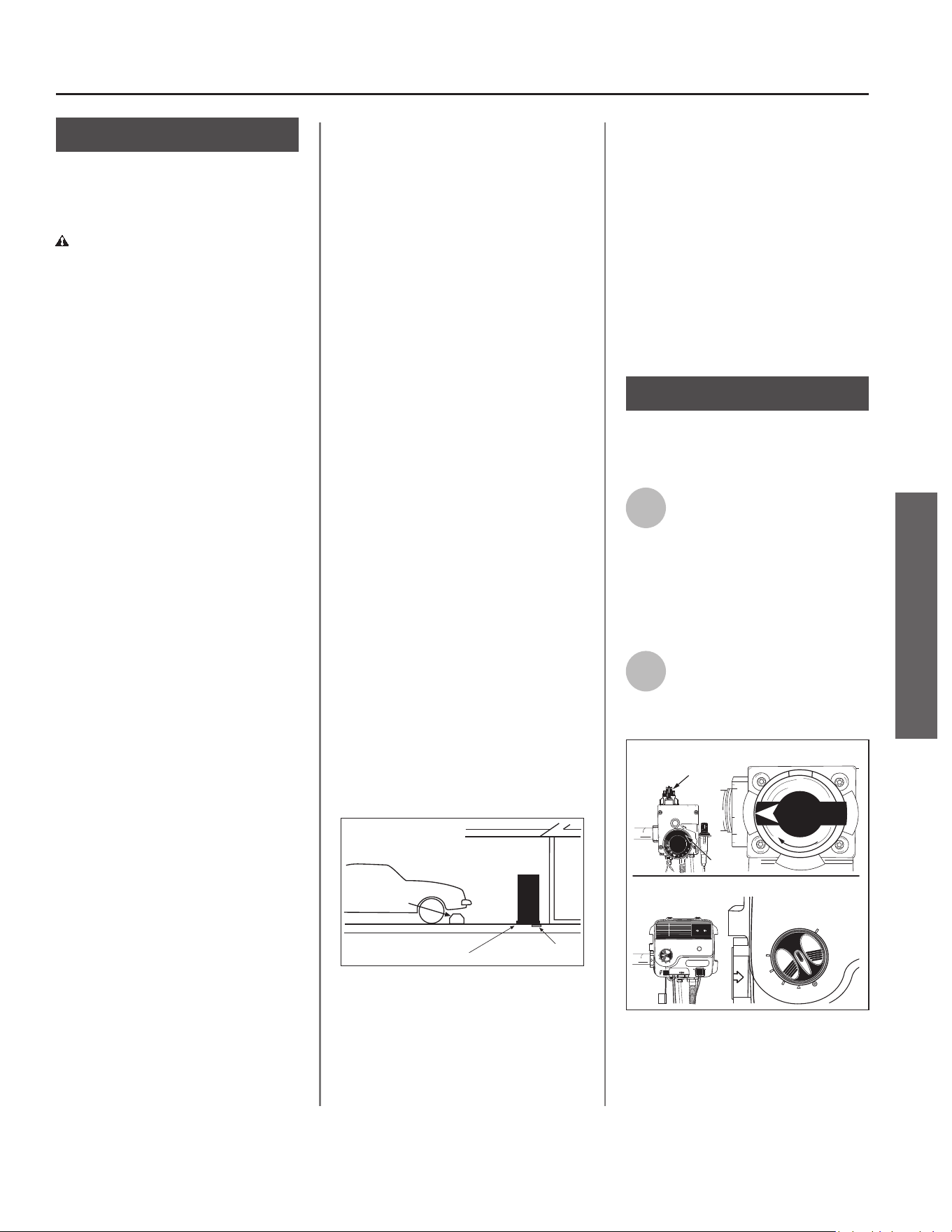
• Do not install in a locaon prone to
physical damage by vehicles, ood-
ing, or other risks.
Vehicle
Stop
Drain
Drain
Pan
Figure 29 - In a garage, install a vehicle stop to
avoid water heater damage.
• Avoid locaons such as acs, upper
oors, or where leaks might damage
the structure or furnishings. Due
to the normal corrosive acon of
water, the tank will eventually leak.
To minimize property damage from
leaks, inspect and maintain your
water heater in accordance with this
manual’s instrucons. Install a metal
drain pan under the water heater
piped to an adequate drain. Inspect
the drain pan, pipes, and surround-
ing area regularly and x any leaks
found. Drain pans are available at
your local plumbing supplier. Leaks
are frequently in the plumbing sys-
tem itself and not the water heater.
Step: 3
Removing the Old
Water Heater
1
Read each installaon step
and decide if you have the
necessary skills to install the
water heater. Only proceed if you are
comfortable you can safely perform
the work. If you are not sure, have a
qualied person perform the
installaon.
2
On the old water heater, turn
the control knob on the gas
control valve to the OFF
posion.
Mechanical Valve
P
I
L
O
T
O
N
O
F
F
T
u
r
n
TO LIGHT
/
HOLD
IGNITER
RELEASE KNO
Electronic Valve
P
I
Press down to turn
Turn to
pilot
SCALDING
RISK
INCREASES
WITH
HOTTER
WATER
HOT
LOW
PILOT
OFF
VERY
HOT
A
B
C
VAC
TO LIGHT PILOT:
PRESS
/
HOLD
KNOBIN
POSITION
PRESS
IGNITER
BUTTON
UNTIL
PILOTLIGHTS
RELEASEKNOB
WHEN
STATUS
LIGHT
BLINKS
STATUS
RED
WHITE
FLAMES
STATUS
1
2
3
4
5
6
7
STATUS
LIGHT
CODE
SCALDING
RISK
INCREASES
WITH
HOTTER
WATER
HOT
LOW
PILOT
OFF
VERY
HOT
A
B
C
VAC
PRESS
PRESS
L
O
W
V
E
R
Y
H
O
T
L
O
T
L
I
G
H
T
I
N
G
A
B
C
I
P
CAUTION:
RISK OF SCALDING
INCREASES WITH
HOTTER WATER
Figure 30 - Turn gas control/temperature knob
OFF.
18 • Residenal Gas Water Heater Use and Care Guide
3
Turn the manual gas valve for
the water heater’s supply line
OFF.
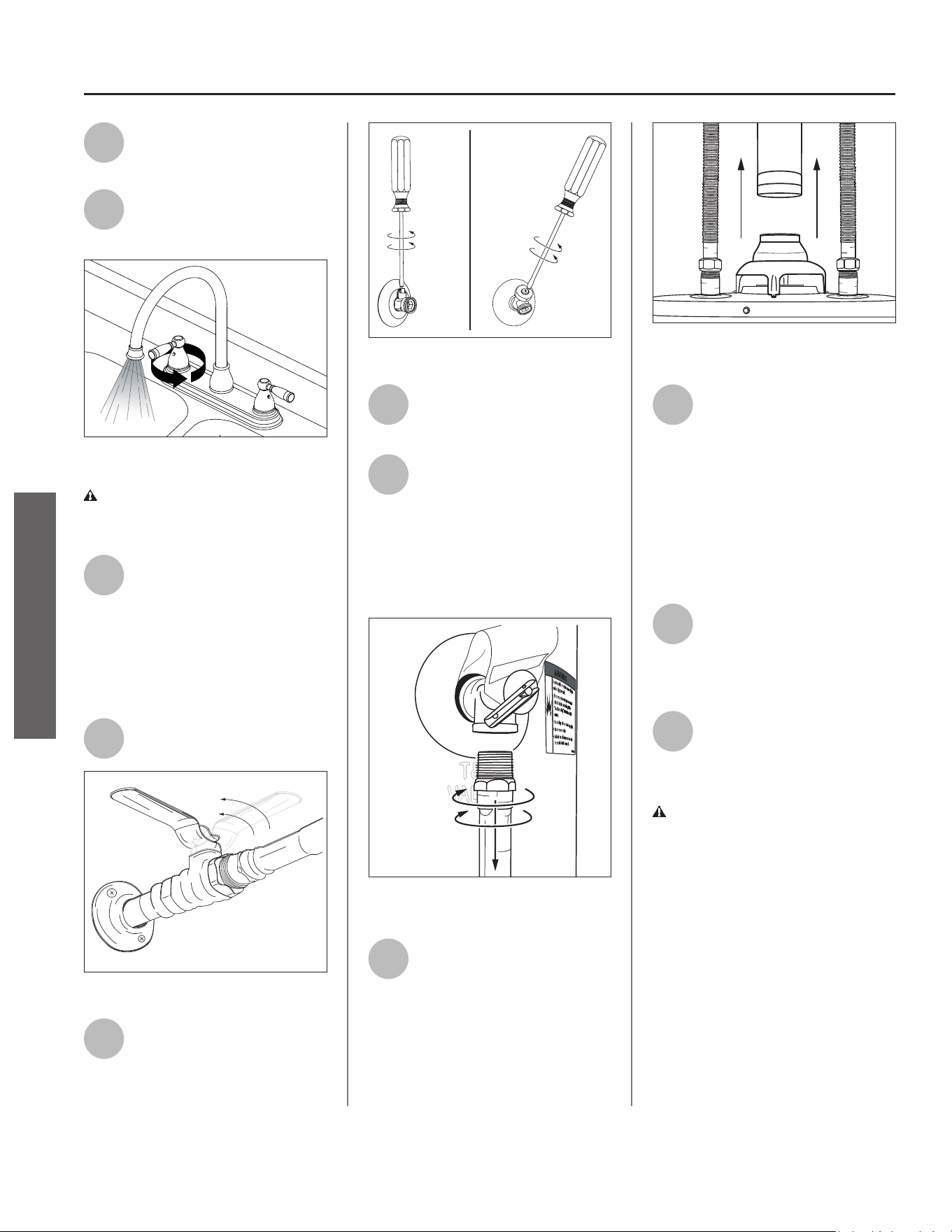
4
Open a hot water faucet and
let the hot water run unl it
is cool.
Figure 31 - Let the hot water run unl it is cool.
WARNING! Be sure the water
runs cool before draining the tank to
reduce the risk of scalding.
5
Connect a garden hose to the
drain valve and place the
other end of the hose in a
drain, outside, or in buckets (sediment
in the boom of the tank may clog
the valve and prevent it from draining.
If you cannot get the tank to drain,
contact a qualied person).
6
Turn the cold water supply
valve OFF.
Figure 32 - Cold water supply in OFF posion.
7
Open the drain valve on the
water heater.
Figure 33 - Draining the old water heater.
8
Also open a hot water faucet
to help the water in the tank
drain faster.
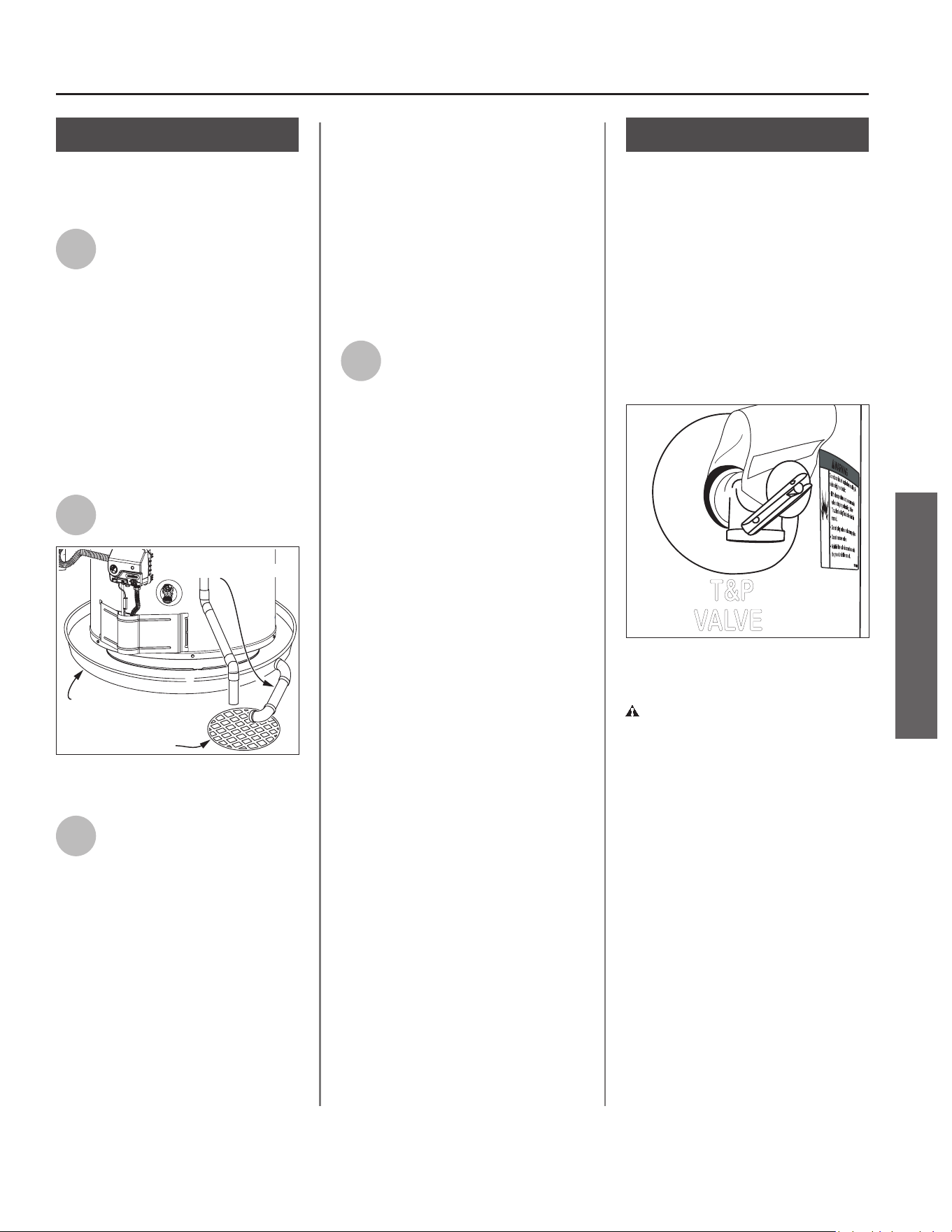
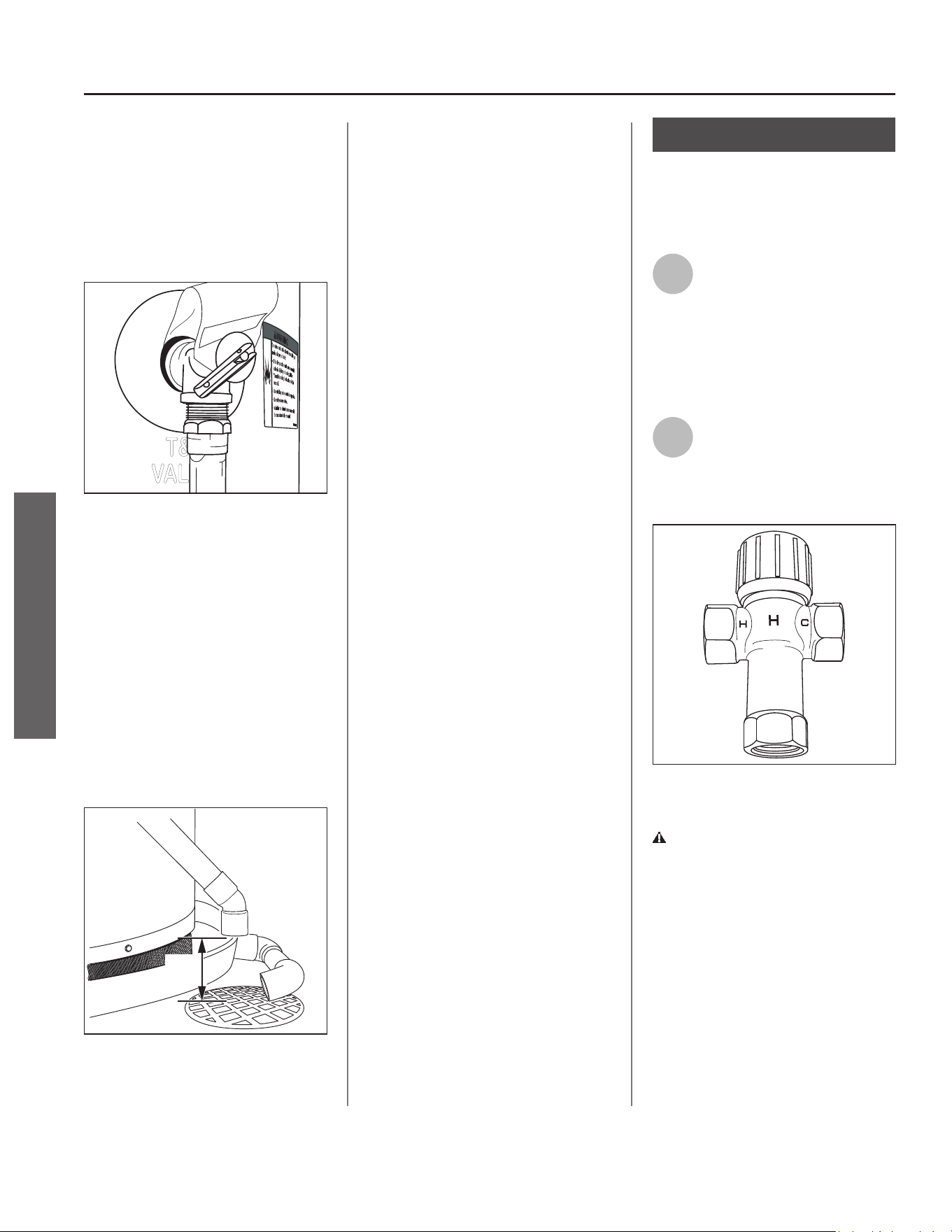
9
When the tank is empty,
disconnect the Temperature
& Pressure (T&P) Relief Valve
discharge pipe. You may be able to
reuse the discharge pipe, but do not
reuse the old T&P Relief Valve. A new
T&P Relief Valve comes with your new
water heater.
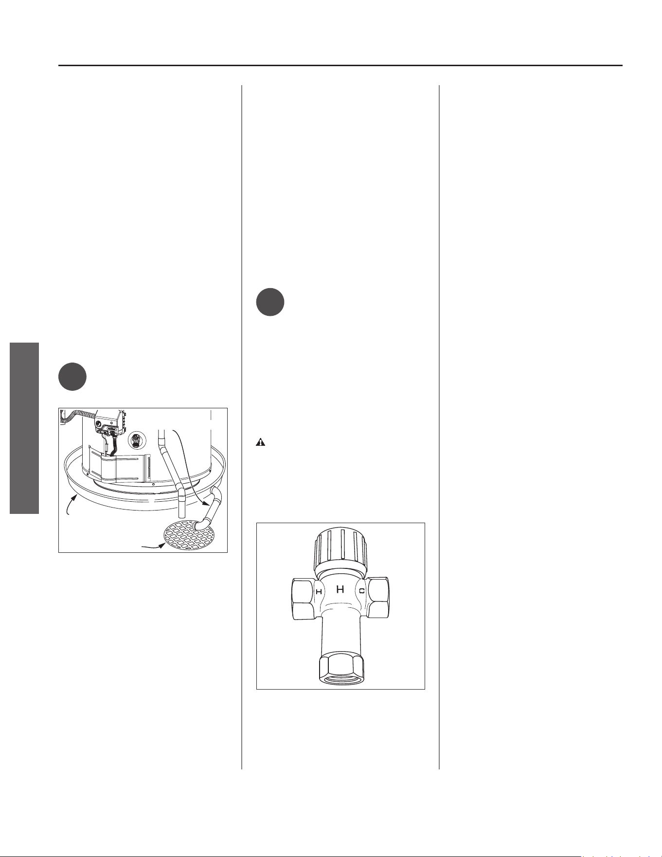
Figure 34 - Removing the T&P Relief Valve
discharge pipe.
10
Allow the vent pipe and dra
hood to cool. Once cooled,
disconnect the vent pipe
from the dra hood. You may need to
support the vent pipe unl the new
water heater is in place.
Figure 35 - Disconnect the vent pipe from the
dra hood.
11
Disconnect the water pipes.
Many water pipes are
connected by a threaded
union which can be disconnected with
wrenches. If you must cut the water
pipes, cut the pipes close to the water
heater’s inlet and outlet connecons,
leaving the water pipes as long as
possible. If necessary, you can make
them shorter later when you install
the new water heater.
12
Conrm the manual gas valve
for the water heater’s supply
line is turned OFF. Disconnect
the gas line from the water heater’s
gas control valve and cap it.
13
Remove the old water heater.
Use an appliance dolly or
hand truck to move the water
heater.
WARNING! Use two or more
people to remove or install a water
heater. Failure to do so can result in
back or other injury.
INSTALLATION
INSTALLATION
Residenal Gas Water Heater Use and Care Guide • 19
INSTALLATION
INSTALLATION
Step: 4
Installing the New
Water Heater
1
Completely read all
instrucons before beginning.
If you are not sure you can
safely complete the installaon, seek
assistance from any of the following
sources:
• Schedule an appointment with a
qualied person to install your water
heater.
• Call our Technical Assistance Hotline
which is listed on the water heater’s
warranty sheet.
2
Install a metal drain pan that
is piped to an adequate drain.
Drain
Drain Pan
Drain Pan
Discharge Pipe
Figure 36 - Metal drain pan piped to an ade-
quate drain.
3
Set the water heater in place
taking care not to damage
the drain pan. When installing
directly on carpet, the water heater
must be installed on a wood or metal
base that extends beyond the
dimensions of the water heater (width
and depth) by at least 3 inches in any
direcon. If the water heater is
installed on carpet in an alcove or
closet, the enre oor must be
covered by a wood or metal panel.
NOTICE: Most codes require seng
the water heater in a metal drain pan
piped to an adequate drain. The drain
pan helps avoid property damage
which may occur from condensaon
or leaks in the piping connecons or
tank. The drain pan must be at least
two inches wider than the diameter
of the water heater. Install the drain
pan so the water level is limited to a
maximum depth of 1-¾”.
4
Verify the water heater is
properly set in place. Check
that:
• There is adequate space to install
the T&P Relief Valve discharge pipe
and that it can be piped to a sep-
arate drain (and not into the drain
pan, unless otherwise allowed by
local and state codes).
• There is adequate access and space
around the water heater for future
maintenance.
• The water heater is installed ver-
cally.
Step: 5
Connect the
Temperature and
Pressure (T&P) Relief
Valve/Pipe
Most T&P Relief Valves are pre-
installed at the factory. In some cases,
they are shipped in the carton and
must be installed in the opening
marked “T&P Relief Valve” and
according to local codes.
Figure 37 - Temperature and Pressure Relief
Valve
WARNING! To avoid serious injury
or death from explosion, install a
T&P Relief Valve according to the
following instrucons.
If the T&P Relief Valve was not factory
installed, install the new T&P Relief
Valve that came with your water
heater. Do not reuse an old T&P
Relief Valve. Install a T&P Relief Valve
discharge pipe according to local
codes and the following guidelines:
• The discharge pipe should be at
least ¾” inside diameter and sloped
for proper drainage. Install it to
allow complete drainage of both the
T&P Relief Valve and the discharge
pipe.
20 • Residenal Gas Water Heater Use and Care Guide
• The discharge pipe must not be
smaller than the pipe size of the
T&P Relief Valve. The pipe must also
be able to withstand 250°F (121°C)
without distoron. Use only copper
or CPVC pipe. Do not use any other
type of pipe, such as PVC, iron, exi-
ble plasc pipe, or any type of hose.
Figure 38 - The T&P Relief Valve discharge pipe
must be installed properly and piped to an
adequate drain.
• Terminate the discharge pipe a
maximum of six inches above a
oor drain or outside the building.
Do not drain the discharge pipe
into the drain pan; instead pipe it
separately to an adequate drain.
In cold climates, terminate the
discharge pipe inside the building to
an adequate drain. Outside drains
could freeze and obstruct the drain
line — protect the discharge pipe
from freezing.
Dicharge
Pipe
Drain
Pipe
6.00"
MAX
Figure 39 - Temperature and Pressure Relief
Valve Discharge Pipe
• Do not place any valve or other re-
stricon between the tank and T&P
Relief Valve. Do not cap, block, plug,
or insert any valve between the T&P
Relief Valve and the end of the dis-
charge pipe. Do not insert or install
any reducer in the discharge pipe.
Step: 6
Install Shut-O and
Thermostac Mixing
Valves
1
If one is not already installed,
install a manual shut-o valve
in the cold water line that
supplies the water heater. Install the
shut-o valve near the water heater
so that it is readily accessible. Only
use a full-ow ball or gate valve
compable with potable water.
2
Install a Thermostac Mixing
Valve at each point-of-use
(for example, kitchen sink,
bathroom sink, bath, shower) per the
valve manufacturer’s instrucons.
MIX
Figure 40 - Install Thermostac Mixing Valves at
each point where hot water will be used.
WARNING! Even if the water
heater’s thermostat is set to a
relavely low temperature, hot water
can scald. Install Thermostac Mixing
Valves at each point-of-use to reduce
the risk scalding.
INSTALLATION
INSTALLATION
Residenal Gas Water Heater Use and Care Guide • 21
INSTALLATION
INSTALLATION
IF YOU HAVE COPPER PIPES:
If your home has copper water
pipes, you can solder the water pipe
connecons or use compression
ngs which do not require
soldering. Compression ngs
are easier to install than soldering
pipe. Check with local plumbing
ocials to determine what types of
pipe materials are suitable for your
locaon. Do not use lead-based
solder.
Compression ngs don’t require soldering.
NOTICE: Do not solder pipes while
they are aached to the water heater.
The water heater’s inlet and outlet
connecons contain non-metallic
parts which could be damaged. The
proper way to connect the water
heater to copper water pipes is as
follows:
• Solder a short length of pipe (about
a foot or so) to a threaded adapt-
er using only 95/5 n-anmony
or equivalent solder. Aach the
threaded adapters to the water
heater’s connecons (using thread
sealant tape or pipe joint com-
pound). Connect the home’s water
pipes by soldering, keeping the
connecons at the water heater
cool with wet rags.
Step: 7
Connect the Water
Supply
Note that all piping and components
connected to the water heater must
be suitable for use with potable water.
1
Determine the type of water
pipes in your home. Most
homes use copper water
pipes, but some use CPVC or cross-
linked polyethylene (PEX). Use ngs
appropriate for the type of pipe in
your home. Do not use iron or PVC
pipe – they are not suitable for
potable water.
2
Connect the cold water
supply using ¾ inch Naonal
Pipe Thread “NPT” to the
cold water inlet nipple.
For ease of removing the water heater
for service or replacement, connect
the water pipes with a coupling called
a union. We recommend using a
dielectric-type union (available at your
local plumbing supplier). Dielectric
unions can help prevent corrosion
caused by ny electric currents
common in copper water pipes and
can help extend the life of the water
heater.
NOTICE: Most water heater models
contain energy saving heat traps in
the inlet and outlet connecons. Do
not remove the heat traps.
3
Connect the hot water supply
using ¾” NPT to the hot water
outlet. Follow the same
connecon guidelines as for the cold
water supply.
4
Install insulaon (or heat
tape) on the water pipes
especially if the indoor
installaon area is subject to freezing
temperatures. Insulang the hot
water pipes can increase energy
eciency.
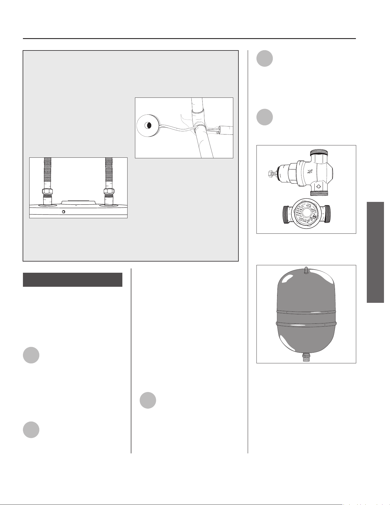
5
Adjust (or install) the home’s
Pressure Reducing Valve to
50-60 psi and install a
Thermal Expansion Tank.
Figure 41 - A Pressure Reducing Valve is re-
quired if your home’s water pressure is above
80 psi.
Figure 42 - The Thermal Expansion Tank should
be pressurized with air to match the home’s
incoming water pressure.
22 • Residenal Gas Water Heater Use and Care Guide
Step: 8
Verify Connecons and
Completely Fill Tank
To remove air from the tank and allow
the tank to ll completely with water,
follow these steps:
1
Remove the ow restrictor at
the nearest hot water faucet.
This allows debris in the
plumbing system to be washed out of
the pipes.
2
Turn the cold water supply
back on and ll the tank.
Figure 43 - Fully open the cold water supply
valve.
3
Open a hot water faucet and
allow the water to run unl it
ows with a full stream.
4
Let the water run full stream
for three minutes.
5
Close the hot water faucet
and replace the ow
restrictor.
6
Check the inlet and outlet
connecons and water pipes
for leaks. Dry pipe
connecons so that any drips or leaks
will be apparent. Repair any leaks.
Almost all leaks occur at connecons
and are not a tank leak.
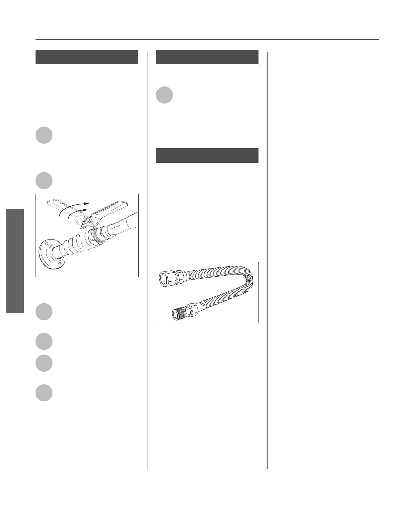
Step: 9
Install Vent Pipe
1
Install the new vent pipe on
top of the water heater. Do
not reuse the vent pipe from
the old water heater, but rather use
the new one that came with your new
water heater. Follow “Venng” on
page 8.
Step: 10
Make Gas Connecons
The Gas Water Heater Hook-Up Kit
(available at your local plumbing
supplier) includes a exible gas
connector with compression ngs
to connect the home’s gas line
to the water heater’s gas control
valve. Follow the kit’s installaon
instrucons to aach the exible gas
connector.
Figure 44 - Flexible Gas Line Connector
Once you have made the gas
connecons, use a small, so-bristled
brush to apply a hand dishwashing
soap and water mixture or children’s
soap bubbles (1 part soap to 15 parts
water) to all connecon points of the
gas line and exible gas connector (if
used). Make sure to generously coat
all the connecons and check for
gas leaks (which will appear as small
bubbles). If any leaks are detected,
turn the gas supply o, ghten the
leaking connecons and re-check.
INSTALLATION
INSTALLATION

Residenal Gas Water Heater Use and Care Guide • 23
INSTALLATION
BEFORE LIGHTING THE WATER
HEATER...
Make sure all checklist items have
been completed.
Water Heater Locaon
✓ Centrally located with the water
piping system. Located as close to
gas piping and vent pipe system as
possible.
✓ Installaon area free of corrosive
or ammable materials, liquids or
vapors.
✓ Proper clearances from combusble
surfaces maintained and sucient
room to service the water heater.
✓ Not installed directly on a carpeted
oor.
✓ Metal drain pan installed and piped
to an adequate drain.
Vent Pipe System
✓ Vent system installed according
to local and state codes or, in the
absence of local and state codes,
the “Naonal Fuel Gas Code”, ANSI
Z223.1 (NFPA 54)-current edion.
✓ Evenly stretched out between water
heater and vent terminaon hood.
✓ Smooth bends with adequate
support to prevent sagging, 0.25”
per foot.
✓ Inside pipe (3”) and outside pipe
(6”) securely fastened to vent termi-
naon hood.
✓ Vent restricter plate installed on
heater ue outlet as applicable.
✓ Inside pipe (3”) and outside pipe
(6”) securely fastened to water
heater with silicone and gear
clamps.
✓ Not obstructed in any way.
Vent Terminaon Hood
✓ Securely fastened to exterior wall.
✓ Above ancipated snow level or 12”
above grade.
✓ Proper clearances from windows,
doors, corners, other vent openings
etc..
✓ Area around vent terminaon hood
clear and unobstructed.
✓ No ammable vapor eming prod-
ucts stored nearby.
✓ Safety covers in place (when appli-
cable).
Water System Piping
✓ Temperature and Pressure Relief
Valve properly installed with a dis-
charge line run to an adequate drain
and protected from freezing.
✓ Water pipes free of leaks.
✓ Water heater completely lled with
water.
✓ Thermal Expansion Tank installed.
✓ Water Pressure Reducing Valve
installed and properly adjusted to
50-60 psi.
✓ Thermostac Mixing Valves installed
at each point-of-use.
Gas Supply and Piping
✓ Gas type is the same as that listed
on the water heater’s data plate.
✓ Gas line equipped with shut-o
valve.
✓ Adequate gas pipe size and ap-
proved gas pipe material.
✓ All gas connecons and ngs leak
checked and any leaks corrected.
INSTALLATION

24 • Residenal Gas Water Heater Use and Care Guide
Lighng Instrucons
WARNING! Explosion Hazard —
Replace viewport if glass is missing or
damaged. Failure to do so can result
in death, explosion or re.
Read and understand these direcons
thoroughly before aempng to light
or re-light the pilot. Make sure the
viewport is not missing or damaged.
Make sure the tank is completely
lled with water before lighng the
pilot. Check the data plate near the
gas control valve to ensure the correct
gas type. Do not use this water heater
with any gas other than the one listed
on the data plate. If you have any
quesons or doubts, consult your gas
supplier or gas ulity company.
NOTICE: A newly installed water
heater will have air in the gas line. It
may take several lighng aempts to
clear all the air from the gas line and
light the pilot.
Follow these steps to light the pilot:
1
Make sure the manual gas
valve for the water heater’s
supply line is ON.
2
Turn the gas control knob to
the PILOT posion.
3
Press the gas control knob in
fully and hold it in. While
holding in the gas control
knob, repeatedly click the igniter
buon (approximately once per
second) for up to 90 seconds or unl
the Status Light starts to ash. You can
tell the pilot is lit when the Status
Light ashes once every three
seconds.
4
Once the Status Light starts
ashing, release the gas
control knob. Adjust the gas
control knob to the desired
temperature seng.
5
If the Status Light doesn’t
start ashing aer 90
seconds,release the gas
control knob and wait 10 minutes.
6
Repeat lighng steps 2
through 5 at least two
addional mes or unl the
Status Light starts ashing once every
three seconds. Wait 10 minutes
between lighng aempts.
7
A solid Status Light means the
pilot was lit but is now o.
Release the gas control knob
and wait 10 minutes. Once the Status
Light goes out, repeat lighng steps 2
through 5.
8
If the Status Light doesn’t
start ashing aer three
lighng aempts, turn the
gas control knob to the OFF posion
and refer to the “Troubleshoong - No
Hot Water” secon (see page 26).
9
When a gas water heater is
rst lit and the tank is cold,
condensaon oen forms
inside the water heater. You may hear
drips or a sizzling sound when the
water heater is rst lit or, you may see
a small puddle on the oor.
Condensaon is not a leak and will go
away once the tank reaches normal
operang temperature.
Shut Down Instrucons
Turn the gas control/temperature
knob counterclockwise to the “OFF”
seng. The status light will stop
blinking and stay on for a short me
aer the water heater is turned o.
Emergency Shut Down
Should overheang occur or the gas
supply fail to shut o , turn o the
water heater’s manual gas control
valve and call a qualied person.
Check the Vent System
and Air Supply
WARNING! Burn Hazard. Do not
touch the vent, doing so can cause
burns.
Check for obstrucons and/or
deterioraon of the intake air and/
or vent piping and the intake air and
vent terminaons. The combuson
and venlaon air ow must not be
obstructed. Repair and/or replace
immediately as necessary.
NOTICE: Do not reach inside the vent
terminaon while the heater is in
operaon.
Remove any debris that may have
accumulated on the screen in the vent
terminaons.
OPERATION
OPERATION
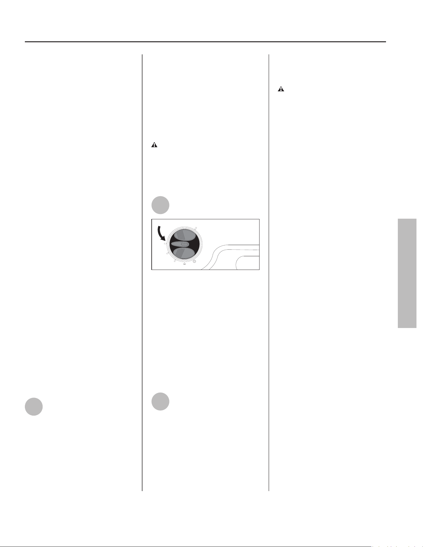
Residenal Gas Water Heater Use and Care Guide • 25
OPERATION
Check all vent system connecons for
damage or deterioraon which could
cause improper venng or leakage of
combuson products. Repair or reseal
as necessary.
Be sure the vent piping is properly
connected to prevent escape of
dangerous ue gases which could
cause deadly asphyxiaon.
Obstrucons and deteriorated vent
systems may present serious health
risk or asphyxiaon.
Chemical vapor corrosion of the ue
and vent system may occur if air for
combuson contains certain chemical
vapors. Spray can propellants,
cleaning solvents, refrigerator and air
condioner refrigerants, swimming
pool chemicals, calcium and sodium
chloride, waxes, bleach and process
chemicals are typical compounds
which are potenally corrosive.
If aer inspecon of the vent system
you found soong or deterioraon,
something is wrong. Call the local
gas ulity to correct the problem and
clean or replace the ue and venng
before resuming operaon of the
water heater.
Temperature Control
System
Adjusng the Temperature
With the installaon steps completed,
you may adjust the water heater’s
temperature seng if desired.
1
Set the gas valve to the
desired temperature. The
“HOT” seng sets the water
temperature to approximately 120°F,
reducing the risk of scald injury. You
may wish to set a higher temperature
to provide hot water for automac
dishwashers or laundry machines, to
provide more hot water capacity, and
to reduce bacterial growth. Higher
tank temperatures (140°F) kill bacteria
that cause a condion known as
“smelly water” and can reduce the
levels of bacteria that cause water-
borne diseases.
Water usage paerns, as well as heat
from sources such as solar collectors,
ambient air, and the pilot light can
result in temperatures higher than the
thermostat set-point.
WARNING! Higher temperatures
increase the risk of scalding, but even
at 120°F, hot water can scald. Install
Thermostac Mixing Valve(s) at each
point-of-use to reduce the risk of
scalding.
2
To adjust the water heater’s
thermostat:
HOT
LOW
PILOT
OFF
VERY
HOT
A
B
C
VAC
TO LIGHT PILOT:
PRESS
/
HOLD
KNOB IN
POSITION
PRESS
IGNITER
BUTTON
UNTIL
PILOT LIGHTS
RELEASE KNOB
WHEN
STATUS
LIGHT
BLINKS
Figure 45 - Adjust the gas control knob to “HOT”.
Turn the gas control knob on the
gas control valve to the right to the
following sengs.
• “A” 128°F
• “B” 138°F
• “C” 147°F
• “VERY HOT” 155°F
NOTICE: The temperatures above are
approximates. The actual temperature
of the heated water may vary.
3
Wait for the water to heat
up. If you have no hot water
aer two hours, refer to the
Troubleshoong Secon (see page
26).
NOTICE: If the tank is full of cold
water, condensaon may form inside
the water heater. This condensaon
may drop on the burner causing a
sizzling sound. In some cases, you
may see a small puddle on the oor.
Condensaon is normal and should go
away once the tank reaches its normal
operang procedure.
WARNING! If you have increased
the temperature seng and the
Thermostac Mixing Valves are not
set properly (or installed) you could
scald yourself while checking the
temperature.
Operang Modes
The gas control valve has two
dierent operang modes: Standard
and Vacaon. The Standard mode
allows you to adjust the water
temperature to your desired seng.
The Vacaon (VAC) mode sets the
thermostat at approximately 55°F
and is recommended when not using
hot water for an extended period of
me. The VAC seng also reduces
energy losses and keeps the tank from
freezing during cold weather but can
cause a Hydrogen gas build up. See
cauon on page 6.
OPERATION
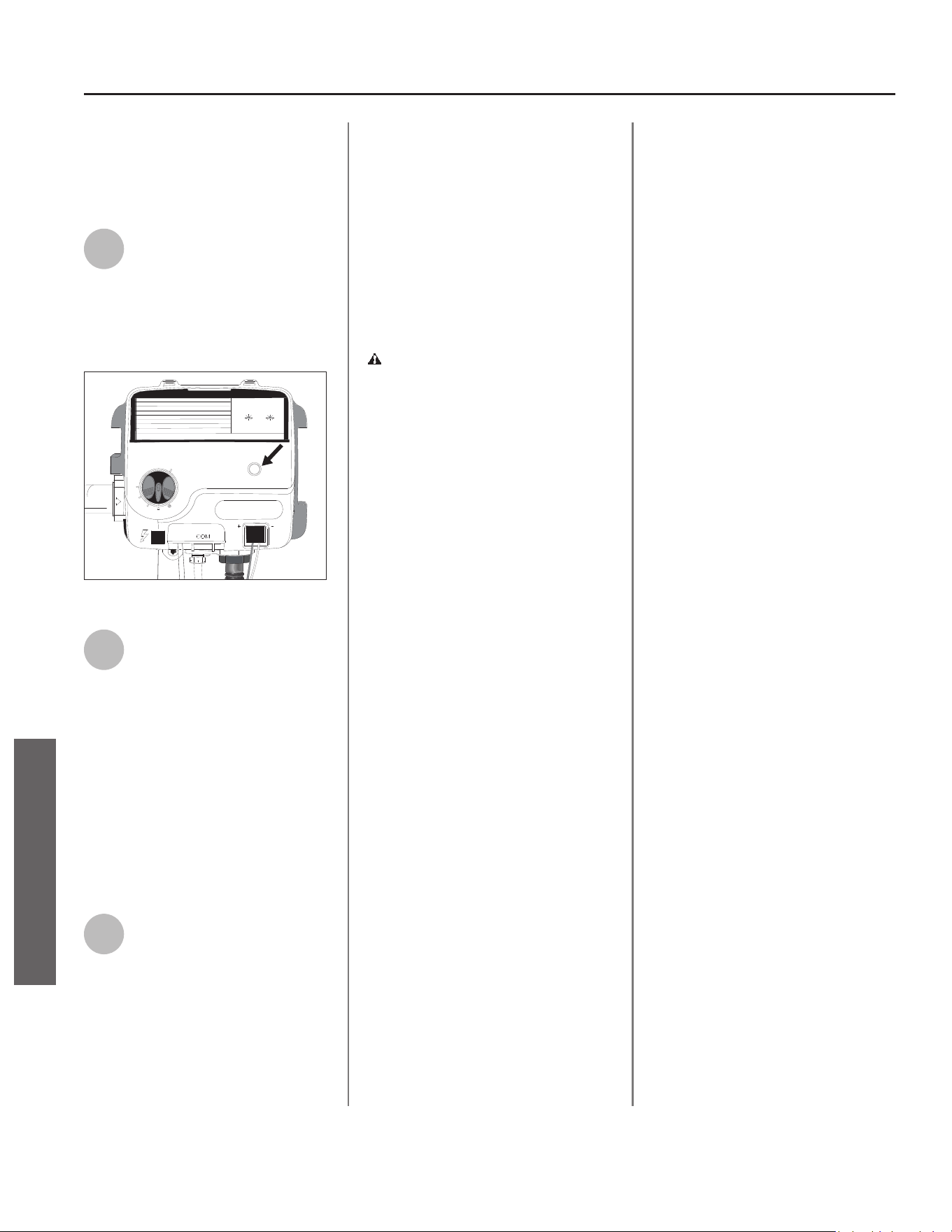
26 • Residenal Gas Water Heater Use and Care Guide
No Hot Water
Use the following step-by-step plan
as a guide to help determine why you
have no hot water:
1
Check the Status Light
The Status Light on the gas
control valve ashes once every three
seconds if the pilot is lit and the gas
control valve has not detected any
problems.
SCALDING
RISK
INCREASES
WITH
HOTTER
WATER
HOT
LOW
PILOT
OFF
VERY
HOT
A
B
C
VAC
TO LIGHT PILOT:
PRESS
/
HOLD
KNOB IN
POSITION
PRESS
IGNITER
BUTTON
UNTIL
PILOT LIGHTS
RELEASE KNOB
WHEN
STATUS
LIGHT
BLINKS
STATUS
RED
WHITE
FLAMES
STATUS
1
2
3
4
5
6
7
STATUS
LIGHT
CODE
Figure 46 - Status Light
2
Status Light is Not
Flashing
If the Status Light is ashing once
every three seconds and you have no
hot water, make sure the gas control
knob is set to HOT.
If the Status Light ashes more than
once every three seconds, refer to
the Status Light Code Troubleshoong
Chart on page 28.
If the Status Light is not ashing, go to
step 3.
3
Checking the Pilot Light
Check the spark igniter. Dim the room
lights and look through the viewport
while clicking the igniter buon.
If you don’t see a spark through the
viewport, check to make sure the
igniter wire is rmly inserted into the
white connector.
If you see a spark, make sure the gas
supply valve is turned on, and try
lighng the pilot using the lighng
instrucons on page 24.
If the pilot sll does not light, call a
qualied person.
Insucient Hot Water
or Slow Hot Water
Recovery
WARNING! Because of the
increased risk from scalding, if you
set the water heater’s thermostat(s)
higher than 120°F, Thermostac
Mixing Valves at each point-of-use
are parcularly important.
If the hot water is simply not warm
enough, there are several possible
causes:
• Faulty Thermostac Mixing Valve in
a faucet or shower control (check
other faucets in the house for hot
water).
• Water heater’s capacity too small
(or usage too high).
• Reversed plumbing connecons or
melted dip tube (usually found soon
aer new installaon).
• Plumbing leak.
• Sediment or lime buildup in the
boom of the tank.
Thermostac Mixing Valves. If the
hot water is simply not warm enough,
make sure the faucet you are checking
doesn’t have a defecve Thermostac
Mixing Valve. Many shower controls
now have built-in mixing valves. If
these devices fail, they can reduce
the amount of hot water the shower
or faucet delivers even though there
is plenty of hot water in the tank.
Always check the water temperature
at several faucets to make sure the
problem is not in a faucet or shower
control.
Undersized Water Heater. If your
water heater runs out of hot water
quickly, it may be too small for your
needs. If the water heater is old,
consider replacing it with a larger
model. If the water heater is in good
condion, you may be able to meet
your family’s hot water needs with
the exisng water heater by installing
Thermostac Mixing Valves at each
point-of-use and then turning the gas
control knob to a higher seng.
You can also reduce your home’s hot
water needs by washing clothes in
cold water, installing ow restrictors
on shower heads, repairing leaky
faucets, and taking other conservaon
steps.
Reversed Connecons or Melted Dip
Tube. Check the hot and cold water
connecons and make sure your
home’s hot water pipe is connected
to the hot water outlet on the water
heater. Usually, reversed connecons
are found soon aer the installaon
of a new unit. If copper pipes were
soldered while they were aached to
the water heater, the dip tube may
have melted. The dip tube is a long,
plasc tube inside the tank aached
to the cold water inlet. If the dip
tube has melted, it can be replaced
by removing the cold water inlet
connecon, removing the old dip tube
and installing a new one.
TROUBLESHOOTING
TROUBLESHOOTING

Residenal Gas Water Heater Use and Care Guide • 27
TROUBLESHOOTING
Plumbing Leak. Even a small leak
in the hot water side of the home’s
plumbing system can make it appear
that the water heater is producing
lile to no hot water. In this case, the
burner will be on all or almost all the
me, yet you will have very lile hot
water. Locate and repair the leak.
Sediment or Lime in Tank. With an
exisng water heater, if you have
some hot water but not as much
as you are used to, there may be a
build up of sediment or lime on the
boom of the tank. Sediment or lime
buildup can reduce the eciency of
your water heater. Heavy deposits
can damage the water heater. See
the Maintenance secon for steps
on draining and ushing the water
heater.
Temperature Too High
Adjust the gas control valve/
thermostat on the water heater
to a lower seng. Install or adjust
Thermostac Mixing Valves at
each point-of-use (see the valve
manufacturer’s instrucons).
Low Water Pressure
Check both the cold and hot water
at a sink to determine if the lower
pressure is only on the hot water side.
If both hot and cold faucets have low
pressure, call your local water ulity.
If the low pressure is only on the hot
water side, the primary causes are:
• Melted heat traps or dip tube. Sol-
dering copper pipes while they are
connected to the water heater can
melt the heat traps inside the hot
and cold water connecons or the
dip tube (cold water side). Melted
heat traps or a melted dip tube can
restrict the ow of hot water. If that
is the case, replace the heat traps or
dip tube.
• Parally closed supply valve. Open
the water heater’s supply valve fully.
Drips from T&P Relief
Valve Discharge Pipe
A small amount of water dripping
from the Temperature and Pressure
(T&P) Relief Valve usually means the
home’s water pressure is too high
and/or you need a Thermal Expansion
Tank. See Step 1 in the Installaon
secon of this manual for more
informaon.
A large amount of hot water coming
from the T&P discharge pipe may be
due to the tank overheang. If the
T&P Relief Valve is discharging large
amounts of very hot water, turn the
gas supply valve o and call a qualied
person.
WARNING! Do not cap or plug
the T&P Relief Valve or discharge
pipe, and do not operate the water
heater without a funconing T&P
Relief Valve — this could cause an
explosion.
Water Pressure Too High. High
water pressure can cause the T&P
Relief Valve to drip. Install a Pressure
Reducing Valve (PRV) on the main cold
water supply line. Adjust the PRV to
between 50 and 60 psi.
Thermal Expansion Tank. Install a
Thermal Expansion Tank. If a Thermal
Expansion Tank is already installed
and the T&P Relief Valve discharge
pipe drips, the home’s water pressure
may be too high or the Thermal
Expansion Tank may be defecve.
Refer to the instrucons that came
with the Thermal Expansion Tank for
more informaon.
Debris. In rare cases, debris can sck
inside the T&P Relief Valve prevenng
the valve from seang fully. In that
case, the T&P Relief Valve discharge
pipe will drip. You may be able to clear
debris from the T&P Relief Valve by
manually operang the valve, allowing
small quanes of water to ush out
the debris. Refer to the T&P Relief
Valve Maintenance secon of this
manual.
WARNING! When manually
operang the Temperature Pressure
Relief Valve, make sure that no one
is in front of or around the discharge
outlet. The water may be extremely
hot and could cause severe burns.
Also ensure that the water discharge
will not cause property damage.
If the water pressure is between 50
and 60 psi, a Thermal Expansion Tank
is installed and properly pressurized,
and the valve has been cleared of any
debris, and it sll drips, the valve may
be broken — have a qualied person
replace the T&P Relief Valve.
Water Odor
Harmless bacteria normally present
in tap water can mulply in water
heaters and give o a “roen egg”
smell. Although eliminang the
bacteria that causes “smelly water”
is the only sure treatment, in some
cases, the standard anode rod that
came with your water heater can be
replaced with a special zinc anode rod
which may help reduce or eliminate
the odor. Contact a qualied person.
NOTICE: To protect the tank, an anode
rod must be installed in the water
heater at all mes or the warranty is
void.
In cases where the “roen egg” smell
is very strong, you could increase the
tank temperature to 140°F in order
to reduce the bacterial growth in the
tank.
WARNING! Because higher
temperatures increase the risk of
scalding, if you set the thermostat(s)
higher than 120°F, Thermostac
Mixing Valves at each point-of-use
are parcularly important.
TROUBLESHOOTING
28 • Residenal Gas Water Heater Use and Care Guide
Status Light and Diagnosc Code Troubleshoong Chart
LED STATUS OR ERROR CODE INDICATES CORRECTIVE ACTION
0 FLASHES (LED NOT LIT) Pilot light is not lit or thermopile has not yet
reached normal operang temperature.
Turn Gas Control Valve/Thermostat knob to “OFF”.
Wait 10 minutes, then aempt to relight Pilot by
following the lighng instrucons on the water
heater’s label. Unl the thermopile reaches its
normal operang temperature, the Status Light
will not blink, even if the Pilot is lit. It may take
up to 90 seconds of connuous Pilot operaon
before the thermopile reaches normal operang
temperature and the Status Light starts to blink. If
the Status Light does not blink aer three lighng
aempts, check to make sure unit is geng
gas. Remove the outer door. Press reset buon.
Replace outer door. Turn Gas Control Valve/
Thermostat knob to “OFF”. Wait 10 minutes, then
aempt to light Pilot by following the lighng
instrucons on the water heater’s label. Look
through the view port for the Pilot ame. If Pilot
is not visible, the spark igniter or gas supply to the
Pilot should be checked. If the Pilot is visible and
the Status Light does not blink aer 90 seconds
of connuous Pilot operaon, the Pilot ame may
not be heang the thermopile suciently (weak
Pilot), the thermopile may be defecve, or wiring
connectors may be loose.
RED LIGHT ON (SOLID) Pilot light was recently exnguished and the
thermopile is cooling down.
Turn Gas Control Valve/Thermostat knob to “OFF”.
Wait 10 minutes for the thermopile to cool, then
aempt to relight Pilot by following the lighng
instrucons on the water heater’s label.
NOTE: This gas control valve/thermostat has
built-in circuitry that requires waing 10 minutes
between lighng aempts.
Unl the thermopile reaches its normal operang
temperature, the Status Light will not blink, even
if the Pilot is lit. It may take up to 90 seconds of
connuous Pilot operaon before the thermopile
reaches normal operang temperature and the
Status Light starts to blink.
1 FLASH (EVERY 3 SECONDS) Normal Operaon No correcve acon necessary.
2 FLASHES Pilot is lit but the thermopile is not producing the
required output voltage.
Turn Gas Control Valve/Thermostat knob to “OFF”.
The thermopile is probably defecve, but loose
wiring connecons or a weak Pilot ame can also
cause this symptom.
4 FLASHES The Gas Control Valve’s temperature sensor has
detected that the water temperature was too high.
Once this condion occurs, the Main Burner and
the Pilot Light will be shut o. Since the Pilot light
will be o, should this condion occur, this Flash
Code will only be displayed immediately aer
the Pilot has been relit. Turn Gas Control Valve/
Thermostat knob to “OFF”.
Relight pilot and verify 4 ashes. If 4 ashes are
observed, turn Gas Control Valve/Thermostat knob
to “OFF”. Turn Main Gas Supply “OFF.” Replace the
Gas Control Valve/Thermostat. See “Removing and
Replacing the Gas Control Valve/Thermostat.”
5 FLASHES The temperature sensor (thermistor) is defecve. Turn Gas Control Valve/Thermostat knob to “OFF”.
Replace the temperature sensor (thermistor).
7 FLASHES Gas Control Valve failure. Turn Gas Control Valve/Thermostat knob to “OFF”.
Turn Main Gas Supply “OFF”. Replace the Gas
Control Valve/Thermostat. See “Removing and
Replacing the Gas Control Valve/Thermostat.”
TROUBLESHOOTING
TROUBLESHOOTING
Residenal Gas Water Heater Use and Care Guide • 29
TROUBLESHOOTING
LED STATUS OR ERROR CODE INDICATES CORRECTIVE ACTION
8 FLASHES This condion only appears if the gas control/
temperature knob has been turned o and the
thermopile connued to produce electric power.
This condion can occur if the thermopile does not
cool down as quickly as expected when the unit
is shut o. This condion can also occur if the gas
control/temperature knob has been turned o and
the pilot connues to operate because the pilot
valve is stuck in the open posion.
Make sure that the gas control valve/thermostat
knob is set to “OFF”. Wait one minute. Remove
the outer door. Look through the sight glass for a
pilot ame. If a pilot ame is observed with the
gas control valve/thermostat knob set to the “OFF”
posion, the pilot valve is stuck open. Turn the
main gas supply “OFF”. Replace the gas control
valve/thermostat. For instrucons, see “Removing
and Replacing the Gas Control Valve/ Thermostat.”
If the pilot ame is not observed when the gas
control valve/thermostat knob is set to the “OFF”
posion, wait 10 minutes for the thermopile to
cool, then aempt to relight the pilot by following
the lighng instrucons on the water heater’s
label. If this condion returns, replace the gas
control valve/thermostat. See “Removing And
Replacing The Gas Control Valve/Thermostat” for
instrucons.
TROUBLESHOOTING
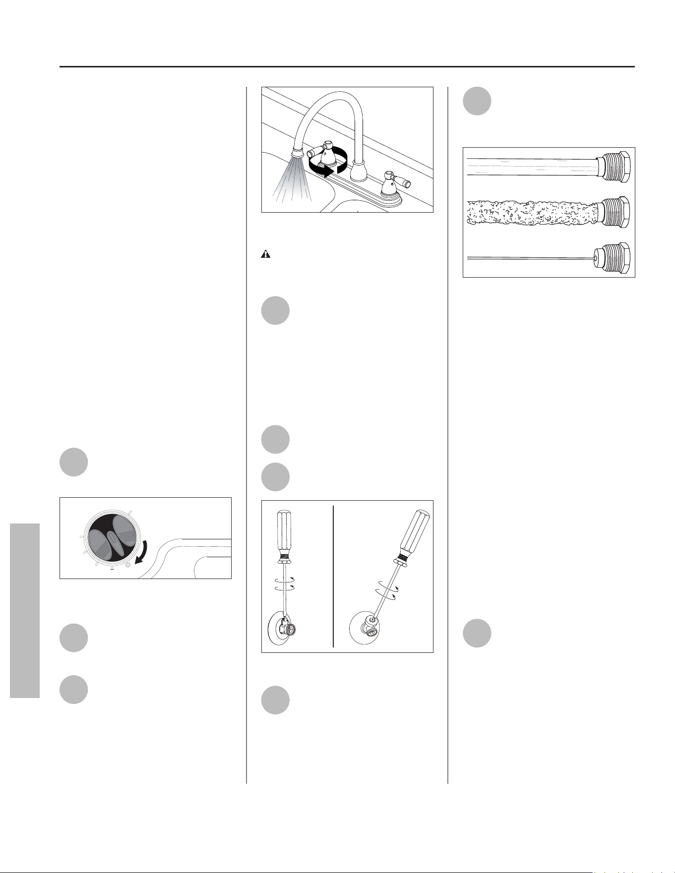
30 • Residenal Gas Water Heater Use and Care Guide
Roune Maintenance
Roune maintenance will help your
water heater last longer and work
beer. If you cannot perform these
roune maintenance tasks yourself,
contact a qualied person.
Draining and Flushing the
Water Heater
Tap water contains minerals that can
form sediment in the boom of the
tank. The amount of lime deposits or
sediment depends on the hardness
of your tap water. The rate at which
sediment builds up depends on water
quality and hardness in your area,
the temperature sengs, and other
variables. We recommend draining
and ushing the water heater aer
the rst six months of operaon to
determine the amount of sediment
build up. Draining sediment extends
the life of the tank and drain valves.
To Drain and Flush the Tank:
1
Turn the gas control knob on
the gas control valve to the
OFF posion.
HOT
LOW
PILOT
OFF
VERY
HOT
A
B
C
VAC
TO LIGHT PILOT:
PRESS
/
HOLD
KNOB IN
POSITION
PRESS
IGNITER
BUTTON
UNTIL
PILOT LIGHTS
RELEASE KNOB
WHEN
STATUS
LIGHT
BLINKS
Figure 47 - Turn gas control/temperature knob
OFF.
2
Turn the manual gas valve for
the water heater’s supply line
OFF.
3
Open a hot water faucet and
let the hot water run unl it
is cool.
Figure 48 - Let the hot water run unl it is cool.
WARNING! Be sure the water
runs cool before draining the tank to
reduce the risk of scalding.
4
Connect a garden hose to the
drain valve and place the
other end of the hose in a
drain, outside, or in buckets. Note
that sediment in the boom of the
tank may clog the valve and prevent it
from draining. If you cannot get the
tank to drain, contact a qualied
person.
5
Turn the cold water supply
valve OFF.
6
Open the drain valve on the
water heater.
Figure 49 - Draining the water heater.
7
Open a hot water faucet to
help the water in the tank
drain faster.
NOTICE: DO NOT aempt to light
the water heater unless the tank is
completely full of water.
8
Remove and inspect the
anode rod and replace if
depleted. The anode rod
requires a 1-1/16” socket.
Figure 50 - Anode rods from new (top) to par-
ally depleted (middle) to fully depleted stage
(boom).
Anode Rod. The anode rod is a
sacricial metal rod that helps avoid
corrosive and premature failure
(leaks) in the tank. The anode rod
is a consumable item. Inspect the
anode rod aer the rst six months of
operaon when you drain and ush
the tank. Replace the anode rod if it
is substanally worn out or depleted.
Thereaer, inspect the anode rod
annually or more frequently if
needed. If you use a water soener,
your anode rod will deplete faster
than normal. Inspect the anode
rod more frequently, replacing the
anode rod if it is depleted. Obtain
a new anode rod at your local
plumbing supplier or have a qualied
person replace it. (Anode rods are a
consumable item and are not covered
under warranty).
9
If a large amount of sediment
was present when the tank
was drained, ush the tank
by opening the cold water supply
valve and leng the water run unl
no more sediment drains from the
tank. Close the drain valve when you
are done.
MAINTENANCE
MAINTENANCE

Residenal Gas Water Heater Use and Care Guide • 31
MAINTENANCE
NOTICE: Do not aempt to light
the water heater unl the tank is
completely full of water. For complete
instrucons on lling the tank, follow
Step 8 in the “Installaon” secon.
10
Rell the tank by opening the
cold water supply valve.
Make sure a hot water faucet
is open and the drain valve is closed.
Allow a hot water faucet to run full for
at least three minutes to make sure
the tank has all the air removed and is
completely full of water. Once you are
certain the tank is completely full of
water, close the hot water faucet.
11
Relight the pilot using the
instrucons on page 24
and adjust the gas control
knob to the desired temperature. It
may take an hour or more for the tank
of cold water to heat up.
Visual Inspecon
On an annual basis, visually inspect
the venng and air supply system,
piping systems, main burner, and pilot
burner.
Check the water heater for the
following:
• Obstrucons, damage, or deterio-
raon in the venng system. Make
sure the venlaon and combuson
air supplies are not obstructed.
• Buildup of soot and carbon on the
main burner and pilot burner. The
burner may be cleaned with soap
and hot water.
• Inspect the burner ames through
the viewport and compare them
to the drawing above. A properly
operang burner should produce a
so blue ame. Blue ps with yellow
inner cones are sasfactory. The ps
of the ame may have a slight yel-
low nt. The ame should not be all
yellow or have a sharp blue-orange
color. Contaminated air may cause
an orange colored ame. Contact a
qualied technician if the ame is
not sasfactory.
Correct Flame
Soft Blue
Figure 51 - Burner Flames
• Leaking or damaged water and gas
piping.
• Remove any ammable, corrosive
or combusble materials near the
water heater.
If you lack the necessary skills
required to properly perform this
visual inspecon or if the burner
needs to be cleaned, get help from a
qualied person.
T&P Relief Valve Maintenance
Figure 52 - T&P Relief Valve
Read and follow the operang and
annual maintenance instrucons
provided by the manufacturer of
the T&P Relief Valve (yellow label
aached to T&P Relief Valve). If no
label is aached to the T&P Relief
Valve, follow the instrucons in this
secon.
Minerals in the water can form
deposits that cause the valve to sck
or create blocked passages, making
the T&P Relief Valve inoperave.
Follow these guidelines:
• At least annually, operate the T&P
Relief Valve manually to ensure the
waterways are clear and the valve
mechanism moves freely (above).
Before opening the valve manually,
check that it will discharge in a place
for secure disposal.
• Aer manually operang T&P Relief
Valve, remove any water in the drain
pan and wipe away any water from
the heater.
WARNING! Hot water will be
released. Before opening the T&P
Relief Valve manually, check that it
will discharge in a safe place. If water
does not ow freely from the end
of the discharge pipe, turn the gas
control knob to the OFF posion and
call a qualied person to determine
the cause.
• At least every ve years, have a
qualied person inspect the T&P
Relief Valve and discharge pipe.
Damage caused by corrosive water
condions, mineral deposits, or
other problems can only be de-
termined when a qualied person
removes and inspects the valve and
its components.
Note that a dripping T&P Relief Valve
is usually caused by the home’s water
pressure being too high and/or lack of
a Thermal Expansion Tank. If your T&P
Relief Valve drips, see page 27.
A T&P Relief Valve that has been
allowed to drip for an appreciable
period of me should be inspected for
mineral buildup.
MAINTENANCE
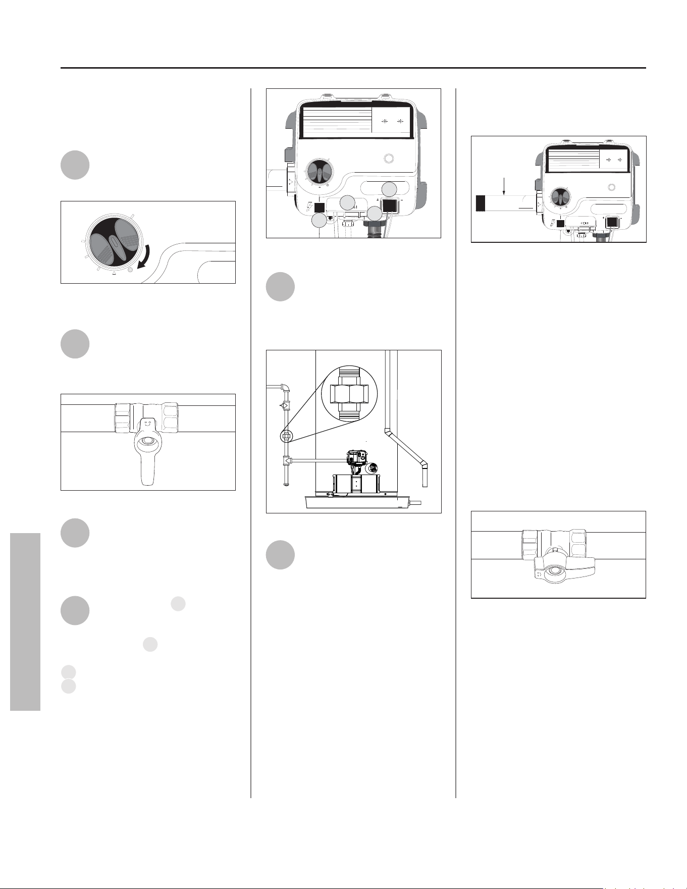
32 • Residenal Gas Water Heater Use and Care Guide
Removing and Replacing the
Gas Control Valve
Removing the Gas Control Valve:
1
Turn the gas control/
temperature knob to the
“OFF” posion.
HOT
LOW
PILOT
OFF
VERY
HOT
A
B
C
VAC
TO LIGHT PILOT:
PRESS
/
HOLD
KNOB IN
POSITION
PRESS
IGNITER
BUTTON
UNTIL
PILOT LIGHTS
RELEASE KNOB
WHEN
STATUS
LIGHT
BLINKS
Figure 53 - Turn gas control/temperature knob
OFF.
2
Turn o the gas at the
manual shut-o valve on the
gas supply pipe.
Figure 54 - Gas valve in “o” posion.
3
Drain the water heater. Refer
to the “Draining and Flushing
the Water Heater” secon
(see page 30) and follow the
procedure.
4
Disconnect the
A
igniter
wire from the igniter lead
wire. Use needle nose pliers
to disconnect the
B
red (+) and
white (-) thermopile wires. Disconnect
C
pilot tube (7/16” wrench) and
D
manifold tube (3/4” wrench) at
the gas control valve/thermostat.
NOTICE: L.P. Gas systems use reverse
(le-hand) threads on the manifold
tube.
SCALDING
RISK
INCREASES
WITH
HOTTER
WATER
HOT
LOW
PILOT
OFF
VERY
HOT
A
B
C
VAC
TO LIGHT PILOT:
PRESS
/
HOLD
KNOB IN
POSITION
PRESS
IGNITER
BUTTON
UNTIL
PILOT LIGHTS
RELEASE KNOB
WHEN
STATUS
LIGHT
BLINKS
STATUS
RED
WHITE
FLAMES
STATUS
1
2
3
4
5
6
7
STATUS
LIGHT
CODE
B
D
C
A
Figure 55 - Gas valve connecons.
5
Disconnect the ground joint
union in the gas piping.
Disconnect the remaining
pipe from the gas control valve/
thermostat.
Figure 56 - Ground joint union connecon.
6
To remove the gas control
valve/thermostat, thread a 4”
secon of gas pipe into the
inlet and use it to turn the gas control
valve/thermostat (counterclockwise.)
Do not use pipe wrench or equivalent
to grip body. Damage may result,
causing leaks. Do not insert any sharp
objects into the inlet or outlet
connecons. Damage to the gas
control valve/thermostat may result.
Replacing the Gas Control Valve:
To replace the gas control valve/
thermostat, reassemble in reverse
order. When replacing the gas control
valve/thermostat, thread a 4” secon
of gas pipe into the inlet and use it to
turn the gas control valve/thermostat
(clockwise.) DO NOT OVER TIGHTEN,
damage may result.
SCALDING
RISK
INCREASES
WITH
HOTTER
WATER
HOT
LOW
PILOT
OFF
VERY
HOT
A
B
C
VAC
TO LIGHT PILOT:
PRESS
/
HOLD
KNOB IN
POSITION
PRESS
IGNITER
BUTTON
UNTIL
PILOT LIGHTS
RELEASEKNOB
WHEN
STATUS
LIGHT
BLINKS
STATUS
RED
WHITE
FLAMES
STATUS
1
2
3
4
5
6
7
STATUS
LIGHT
CODE
4”
Gas Pipe
Figure 57 - Gas control valve with threaded
pipe.
• Be sure to use approved thread
sealant tape or pipe joint compound
on the gas piping connecons and
ng on the back of the gas control
valve that screws into tank.
• Be sure to remove the pilot ferrule
nut from the new gas control valve/
thermostat.
• Turn the gas supply on and check for
leaks. Test the water heater with the
main burner on by brushing on an
approved noncorrosive leak detec-
on soluon. Bubbles forming indi-
cate a leak. Correct any leak found.
Figure 58 - Gas valve in “on” posion.
• Be sure tank is completely lled with
water before lighng and acvang
the water heater. Follow the “Light-
ing Instrucons” on page 24.
• If addional informaon is required,
contact our Technical Assistance
Hotline which is listed on the water
heater’s warranty sheet.
MAINTENANCE
MAINTENANCE
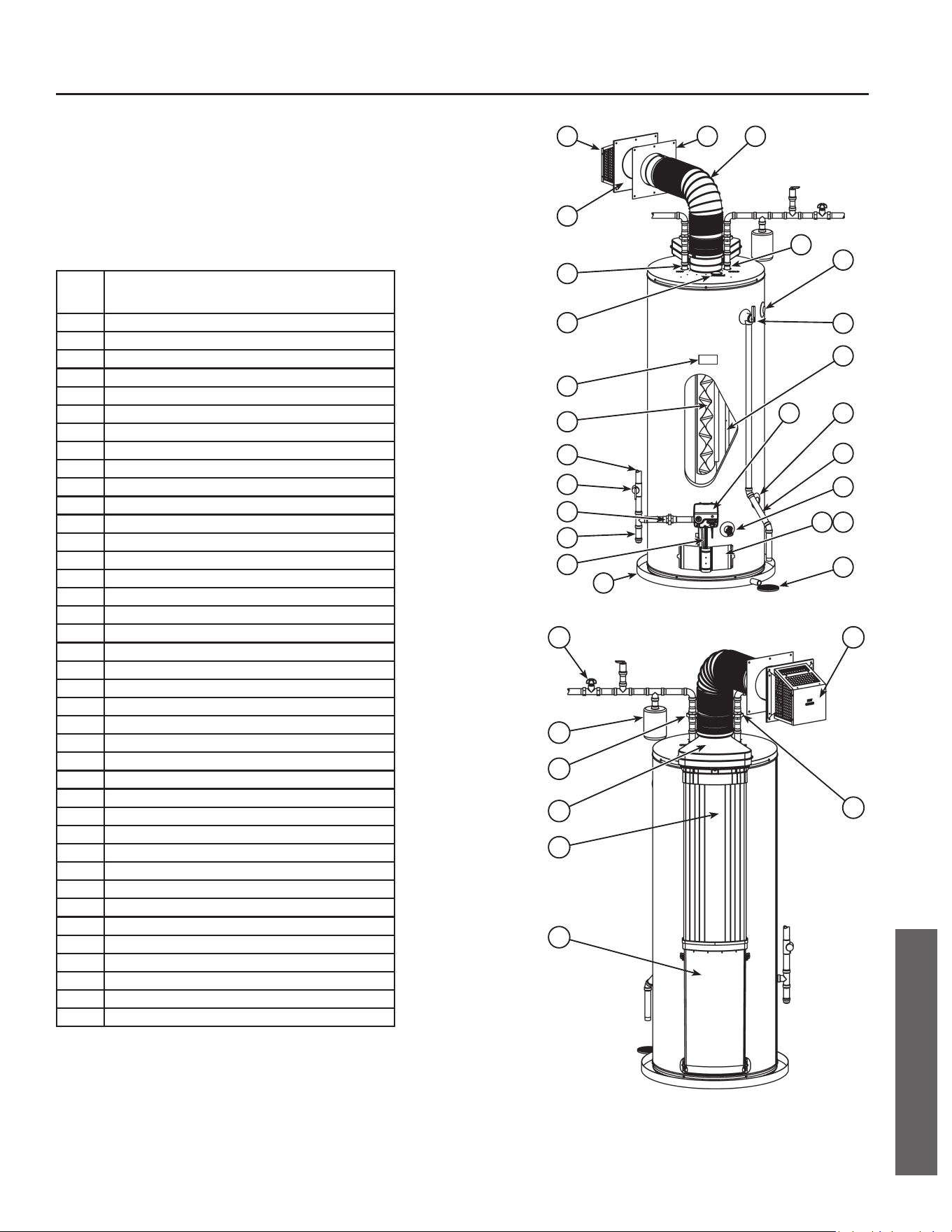
Residenal Gas Water Heater Use and Care Guide • 33
REPAIR PARTS
When ordering repair parts always give the following informaon:
1. Model, serial, and product number
2. Item number
3. Parts Descripon
Repair Parts List
Item
No.
Parts Descripon
1 Vent Terminaon Hood
2 Wall Plate
3 Vent Pipe
4 Cold Water Inlet Nipple/Diptube
5 Side Connect - Hot Outlet
6 T&P Valve
7 Gas Control Valve/Thermostat
8 Side Connect - Cold Inlet
9 Discharge Pipe
10 Drain Valve
11 Outer Gas Door
12 Manifold Door Assembly (behind outer door)
13 Floor Drain
14 Metal Drain Pan
15 Flexible Manifold Tube
16 Sediment Trap
17 Ground Joint Union
18 Manual Gas Shut-o Valve
19 Gas Supply
20 Bae Assembly
21 Rang Plate
22** Anode Rod (Under Cap)
23 Hot Water Outlet
24 Inlet Water Shut-o Valve
25 Union (Water Connecon)
26 Air Inlet Snorkel
27 Air Tower
28 Airbox
29 Thermal Expansion Tank
30* ULN Burner
31* Igniter
32* Pilot
33* Manifold Door Gasket
34* Manifold Door
35* Two Piece Grommet with Clip
36* Viewport
37* Flexible Manifold Tube
38* Thermopile
39* Orice
*Pictured on next page.
**Not shown.
REPAIR PARTS
1
2
23
22
21
20
19
18
17
16
15
14
13
12
11
10
9
87
4
6
5
4
2 3
Front View
Rear View
1
25
24
29
25
28
27
26
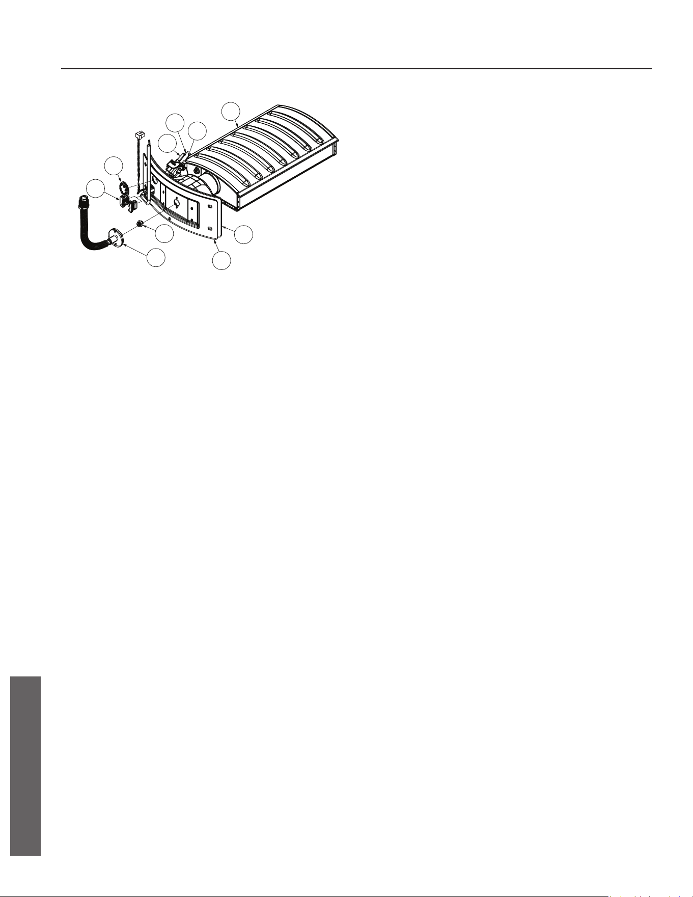
34 • Residenal Gas Water Heater Use and Care Guide
37
33
35
36
34
30
38
32
31
39
REPAIR PARTS
REPAIR PARTS

Residenal Gas Water Heater Use and Care Guide • 35
NOTES
NOTES

Copyright © 2023
All Rights Reserved