Installation and User’s Manual for
Remote Condenser Modular Cuber
Prodigy Elite® A Series Models MC0530,
MC0630, MC0830, MC1030

June 2022
Page 1
MC0530 through MC1030
Remote Cooled User Manual
Introduction
The design of this modular remote cuber is the result
of years of experience with remote ice machine
refrigeration systems. Standard features of this
product include front accessible on-o switches,
always-visible indicator lights, mechanical assist ice
harvest for extra eciency, automatically adjusting
water purge and a control system that optimizes
system operation.
In addition, the Scotsman ICELINQ® app allows users
to connect to the machine via Bluetooth® to monitor,
control, and maintain the ice machine.
This installation and user manual is divided into
three sections: Installation, Use and Operation and
Maintenance.
The Installation section provides the trade person with
the information needed to properly install and start
up this ice system. The Use and Operation section
provides the user with the information needed to use
the machine. The Maintenance section contains the
instructions and schedules for the sanitation and
cleaning of the machine.
Contents
Installation: Product Specications . . . . . . . . . . . . . . . . . . . . . . . . . . . . . . . . . . 2
Model Number Description . . . . . . . . . . . . . . . . . . . . . . . . . . . . . . . . . . . . . . 3
MC0530, MC0630, MC0830 and MC1030 Cabinet Layout . . . . . . . . . . . . . . . . . . . . . . 4
Product Description and Electrical Requirements . . . . . . . . . . . . . . . . . . . . . . . . . . . 5
Water . . . . . . . . . . . . . . . . . . . . . . . . . . . . . . . . . . . . . . . . . . . . . . . . . 6
Panel Removal . . . . . . . . . . . . . . . . . . . . . . . . . . . . . . . . . . . . . . . . . . . . 7
Remote Condenser Location . . . . . . . . . . . . . . . . . . . . . . . . . . . . . . . . . . . . . 8
For The Installer: Remote Condenser . . . . . . . . . . . . . . . . . . . . . . . . . . . . . . . . . 9
Line Set Routing and Brazing . . . . . . . . . . . . . . . . . . . . . . . . . . . . . . . . . . . . . 10
Plumbing Requirements . . . . . . . . . . . . . . . . . . . . . . . . . . . . . . . . . . . . . . . . 11
Electrical . . . . . . . . . . . . . . . . . . . . . . . . . . . . . . . . . . . . . . . . . . . . . . . . 12
Final Check List: . . . . . . . . . . . . . . . . . . . . . . . . . . . . . . . . . . . . . . . . . . . . 13
Initial Start Up . . . . . . . . . . . . . . . . . . . . . . . . . . . . . . . . . . . . . . . . . . . . . 14
Adjustments . . . . . . . . . . . . . . . . . . . . . . . . . . . . . . . . . . . . . . . . . . . . . . 15
Use and Operation . . . . . . . . . . . . . . . . . . . . . . . . . . . . . . . . . . . . . . . . . . 16
Control Switches. . . . . . . . . . . . . . . . . . . . . . . . . . . . . . . . . . . . . . . . . . . . 17
Cleaning, Sanitation and Maintenance . . . . . . . . . . . . . . . . . . . . . . . . . . . . . . . . 18
What to do before calling for service . . . . . . . . . . . . . . . . . . . . . . . . . . . . . . . . . 20
Note any Caution or Warning symbols when they
appear on the product or in this manual. They indicate
potential hazards.
June 2022
Page 2
MC0530 through MC1030
Remote Cooled User Manual
Installation: Product Specications
Location Limitations
This ice system is made up of three parts, the ice
making machine, or head; the remote condenser; and
the interconnecting tubing. The ice making machine
must be installed indoors, in a controlled environment.
Space must be provided near the machine for service
access. The remote condenser may be installed
above or below the ice machine, per the limits stated
later in this manual. The remote condenser may
be installed outdoors within the temperature limits
listed below. The interconnecting tubing must be
installed per the directions stated in this manual,
and the amount of tubing exposed to uncontrolled
temperatures must be minimized.
Space Limitations
Although the machine will function with no clearance
to the top and sides, some space must be allowed
for service access. Building the machine in with no
access will cause higher service cost, in many cases
this extra cost may not be covered by warranty.
Environmental Limitations, ice machine:
Minimum Maximum
Air temperature 50
o
F. 100
o
F.
Water
temperature
40
o
F. 100
o
F.
Water Pressure 20 psi 80 psi
Environmental Limitations, remote condenser
Minimum Maximum
Air temperature -20
o
F. 120
o
F.
Power Supply
Minimum Maximum
115 volt model 104 volts 126 volts
208-230 volt
model
198 volts 253 volts
Warranty Information
The warranty statement for this product is provided
separately from this manual. Refer to it for applicable
coverage. In general warranty covers defects
in material and workmanship. It does not cover
maintenance, corrections to installations, or situations
when the ice machine is operated in circumstances
that exceed the limitations printed above.
Product Information
The machine is a specialized version of a modular
cuber. A modular cuber does not include any ice
storage, it is designed to be placed onto an ice
storage bin or ice dispenser. Many installations only
require the matching bin, but some will need an
adapter to be placed between the ice machine and
the bin or dispenser. Additionally, the machine must
be connected to the correct remote condenser and
use the correct properly sized refrigerant tubing.
The machine is supplied with a full refrigerant charge,
eld charging is not required.
This product cannot be stacked. See the chart for
application information.
June 2022
Page 3
MC0530 through MC1030
Remote Cooled User Manual
Model Number Description
Example
• MC0630SR-32A
• C=cuber
• 06=nominal capacity in 100s of pounds
• 30=nominal width of cabinet in inches
• S=cube size, S=small or half dice, M=medium or
full dice
• R=condenser type. R=Remote
• -32=Electrical code. -32=208-230/60/1, -3= 208-
230/60/3, -1 = 115/60/1
• A=series revision code.
Note: In some areas of this manual model numbers
may include only the rst ve characters of the model
number, meaning that cube size, condenser type and
voltage dierences are not critical to the information
listed there.
Options:
There are several options available for eld
installation. They include:
• KVS, Vari-Smart Adjustable ice level system.
• KBILC, Basic Ice Level Control
• KSB, SmartBoard Advanced feature board.
Some installations require bin or dispenser adapters.
See the table below.
Standard bin applications – Adapter information
Model B530P,
B330P,
B530S
B842S B948S
MC0530,
MC0630,
MC0830,
MC1030
Direct t KBT28 KBT22
Hotel Dispenser
Although an unlikely use for a remote cuber, HD30
can be used without an adapter:
HD30 – use with MC0530R
Ice and Beverage Dispensers - Adapter
Information
Model ID150 ID200 or ID250
MC0530,
MC0630,
MC0830,
MC1030
Does not t KBT44
Other bins and applications:
Note the drop zone and optional ultrasonic sensor
locations in the illustrations.
Scotsman ice systems are designed and
manufactured with the highest regard for safety and
performance. They meet or exceed the standards of
UL and NSF.
Scotsman assumes no liability of responsibility of
any kind for products manufactured by Scotsman
that have been altered in any way, including the use
of any part and/or other components not specically
approved by Scotsman.
Scotsman reserves the right to make design changes
and/or improvements at any time.
Specications and design are subject to change
without notice.
June 2022
Page 4
MC0530 through MC1030
Remote Cooled User Manual
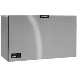
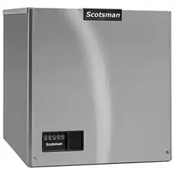
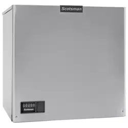
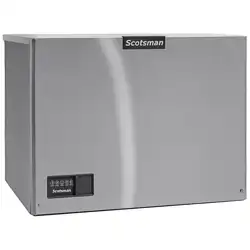
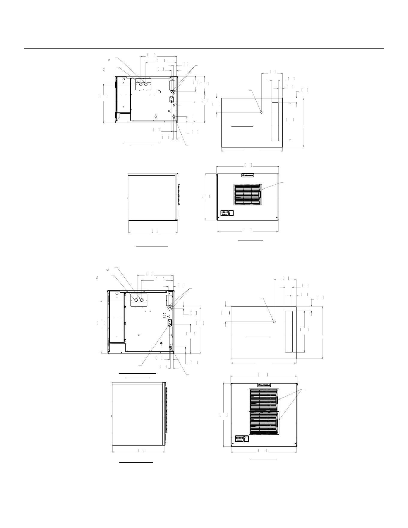
MC0530, MC0630, MC0830 and MC1030 Cabinet Layout
Note: Top number is centimeters, bottom number is inches.
MC0530R, MC0630R
MC0830R, MC1030R
30.00
76.2
22.93
58.3
77.6
30.56
LOUVER AND
REMOVABLE FILTER
AC UNITS ONLY
24.00
61
1.48
3.8
2.63
6.7
1.57
4
15.14
38.5
17.64
44.8
19.04
48.3
3.07
7.8
14.56
37
8.38
21.3
10.82
6.5
2.57
19
7.47
3/4" FPT
DRAIN
3/8" FPT
WATER
INLET
.88" DIA
ELECTRICAL
ACCESS (2)
REMOTE CONDENSER
DISCHARGE LINE
1/2
REMOTE CONDENSER
LIQUID LINE
3/8
24.00
REF.
30.00
REF.
2.00
5.1
2.00
5.1
19.05
48.4
3.25
8.3
10.25
26
7.00
17.8
ICE DROP OPENING
ULTRASONIC
BIN LEVEL
SENSOR
(OPTIONAL)
LEFT SIDE VIEW
FRONT VIEW
REMOTE COOLED
BACK VIEW
PLAN VIEW
24.00
REF.
30.00
REF.
2.00
5.1
2.00
5.1
19.05
48.4
3.25
8.3
10.25
26
7.00
17.8
ICE DROP OPENING
ULTRASONIC
BIN LEVEL
SENSOR
(OPTIONAL)
30.00
76.2
77.67
30.58
73.5
28.93
LOUVERS AND
REMOVABLE FILTERS
AC UNITS ONLY
24.00
61
24.60
62.5
16.54
42
14.63
37.1
2.34
5.9
3.07
7.8
13.47
34.2
1.48
3.8
1.75
4.4
2.2
.88
54.4
21.44
3/8" FPT
WATER
INLET
3/4" FPT
DRAIN
REMOTE CONDENSER
LIQUID LINE
3/8
REMOTE CONDENSER
DISCHARGE LINE
1/2
.88" DIA
ELECTRICAL
ACCESS (2)
LEFT SIDE VIEW
FRONT VIEW
REMOTE COOLED
BACK VIEW
PLAN VIEW
MC0530 through MC1030
Remote Cooled User Manual
April 2026
Page 5
Product Description and Electrical Requirements
Dimensions
w” x d” x h”
Model Series Electrical Use
condenser
Minimum
Circuit
Ampacity
Maximum
Fuse Size*
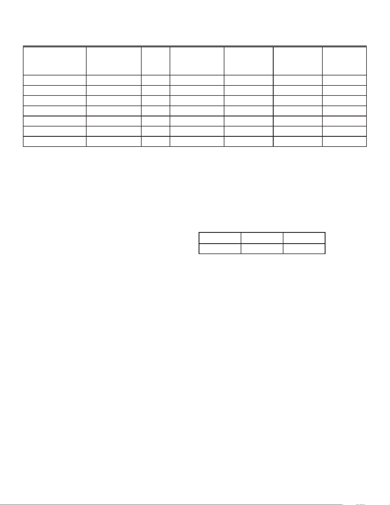
30.75** x 24 x 23 MC0530SR-1 E 115/60/1 ERC111-1 16.2 20
same MC0630SR-1 E 115/60/1 ERC111-1 20 20
same MC0630SR-32 E 208-230/60/1 ERC311-32 10.8 15
30.75** x 24 x 29 MC0830SR-32 E 208-230/60/1 ERC311-32 10 15
same MC0830SR-3 E 208-230/60/3 ERC311-32 8.2 15
same MC1030SR-32 F 208-230/60/1 ERC311-32 12 20
same MC1030SR-3 F 208-230/60/3 ERC311-32 9.6 20
*Or HACR circuit breakers.
** Maximum width at top panel.
Ratings include the remote condenser motor, as it
is designed to be powered by the ice machine. If
connecting remote condenser independently of the
ice machine, use the information on the condenser's
dataplate for fuse and wire sizes.
Table notes: Medium cube models have the same
electrical characteristics as Small. Series revision
code omitted. All the listed condensers include a
headmaster valve.
Central Condenser Coils
The ice machine may be connected to a central
condenser coil. The requirements are:
• Coil – not previously used with mineral oil system.
Virgin coil preferred.
• Correct size (internal volume) and capacity
(BTUH).
• Includes a headmaster valve for discharge
pressure control. Headmaster kit available
for certain MAC condensers, kit number is
RCKCME6GX.
• Fan motor on all the time or controlled to be on
whenever the ice machine is operating.
• Non-Scotsman condensers must have prior
Scotsman Engineering approval for warranty
coverage to be in eect.
Refrigerant tubing kits:
The ice making head’s and the remote condenser’s
refrigeration circuits must be connected. They are
designed to be connected using refrigerant line sets,
supplied in kits of liquid and discharge tubes. Several
lengths are available, order the one that just exceeds
the length needed for the site.
25’ 40’ 75’
BRTE25 BRTE40 BRTE75
No additional refrigerant is required.
Note: Refrigerant charge is supplied with the ice
machine.

June 2022
Page 6
MC0530 through MC1030
Remote Cooled User Manual
Water
The quality of the water supplied to the ice machine
will have an impact on the time between cleanings
and ultimately on the life of the product. Water can
contain impurities either in suspension or in solution.
Suspended solids can be ltered out. In solution
or dissolved solids cannot be ltered, they must be
diluted or treated. Water lters are recommended
to remove suspended solids. Some lters have
treatment in them for dissolved solids. Check with a
water treatment service for a recommendation.
RO water. This machine can be supplied with Reverse
Osmosis water, but the water conductivity must be no
less than 10 microSiemens/cm.
Potential for Airborne Contamination
Installing an ice machine near a source of yeast
or similar material can result in the need for more
frequent sanitation cleanings due to the tendency of
these materials to contaminate the machine.
Most water lters remove chlorine from the water
supply to the machine which contributes to this
situation. Testing has shown that using a lter that
does not remove chlorine, such as the Scotsman
Aqua Patrol, will greatly improve this situation, while
the ice making process itself will remove the chlorine
from the ice, resulting in no taste or odor impact.
Additionally, devices intended to enhance ice machine
sanitation, such as the Scotsman Aqua Bullet, can
be placed in the machine to keep it cleaner between
manual cleanings.
Water Purge
Cube ice machines use more water than what ends
up in the bin as ice. While most water is used during
ice making, a portion is designed to be drained out
every cycle to reduce the amount of hard water scale
in the machine. That’s known as water purge, and an
eective purge can increase the time between needed
water system cleaning. In addition, this product is
designed to automatically vary the amount of water
purged based on the purity of the water supplied to
it. The water purge rate can also be set manually.
Adjustments of purge due to local water conditions
are not covered by warranty.
June 2022
Page 7
MC0530 through MC1030
Remote Cooled User Manual
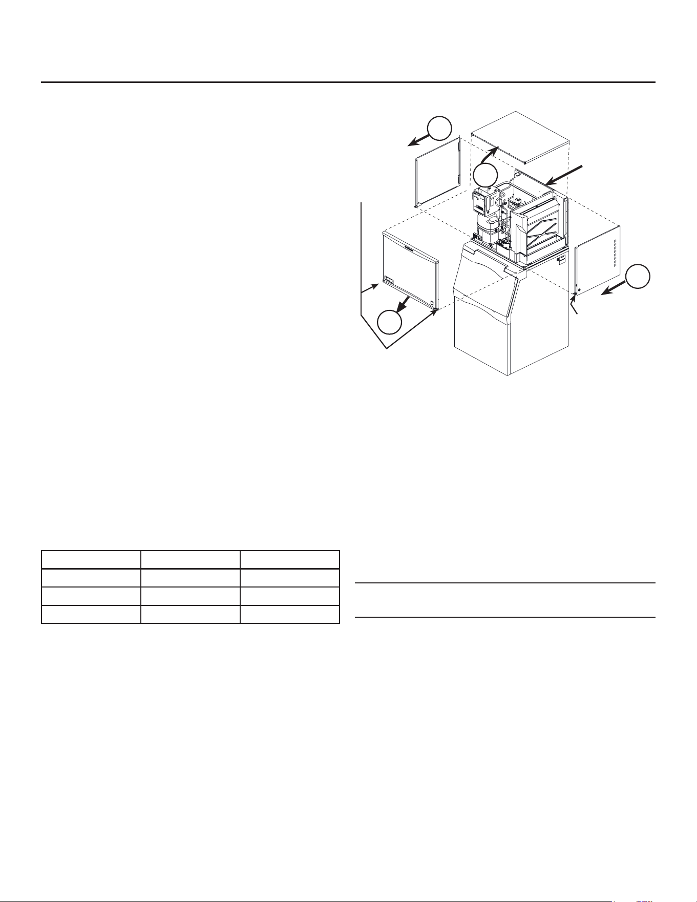
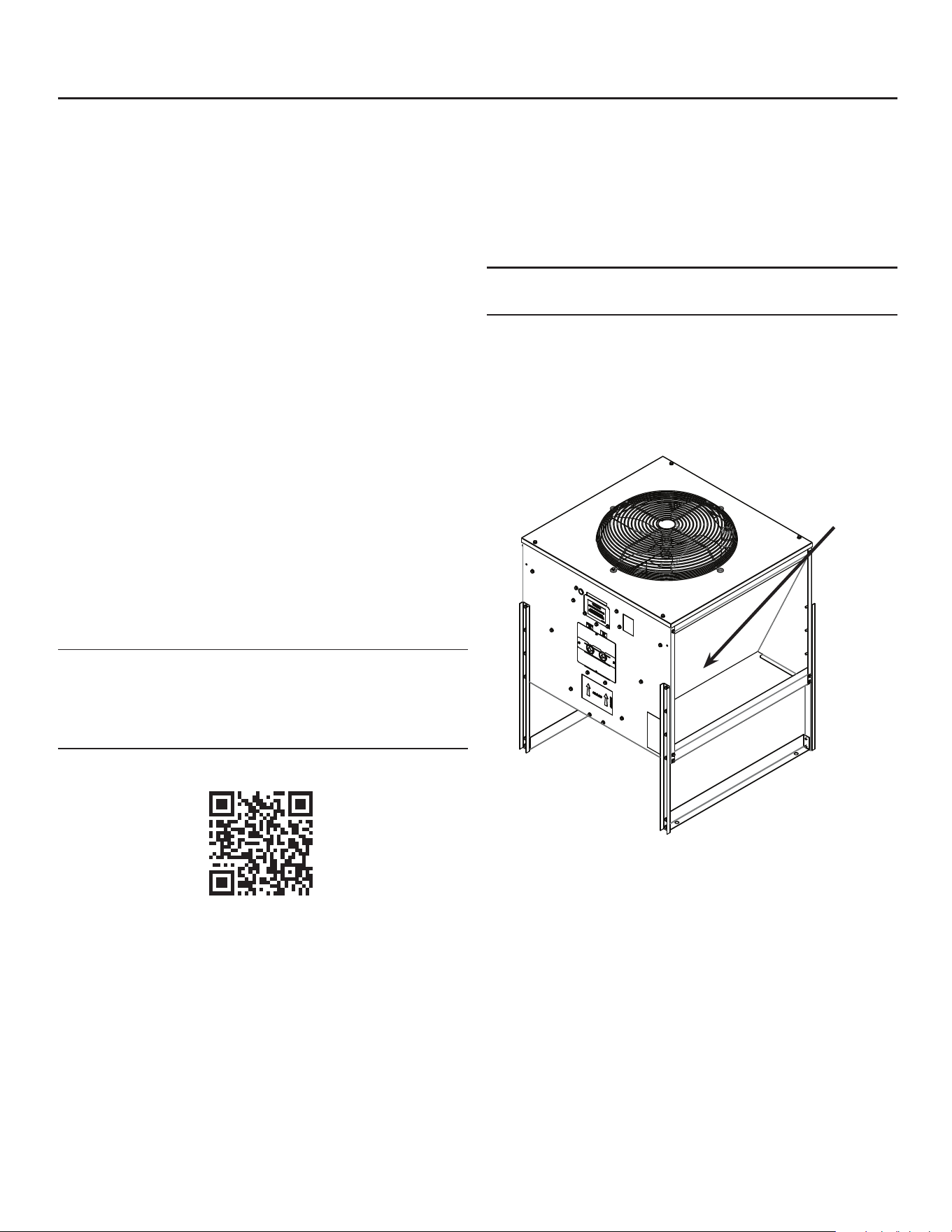
Panel Removal
1. Locate and disengage the two quarter turn
captured screws at the bottom of the front panel.
2. Pull the front panel out at the bottom.
3. Lift the front panel up and o the machine.
4. Remove two screws at the front of the top panel.
Lift up the front of the top panel, push the top
panel back an inch, then lift to remove.
5. Locate and loosen the screws holding each side
panel to the base. Left side panel also has a
screw holding it to the control box.
6. Pull the side panel forward to release it from the
back panel.
This manual covers several models of remote cubers.
The model number on the ice machine can be found
either on the dataplate, which is on the back panel, or
the serial number tag, which is behind the front panel.
See the illustration for the locations of the dataplate
and the serial number tag.
The remote condenser has a separate model and
serial number. Its model and serial number is on the
dataplate on the condenser near the quick connect
ttings.
Write the model and serial numbers here:
Model Serial Number
Ice machine
Bin
Condenser
Write the day of start up here:_______________
Uncrate and Set Up
Begin with the ice storage bin or dispenser. If a bin,
remove the carton, and, using part of the carton as
a cushion, tip the bin on its back to remove the skid.
Attach the supplied legs or optional casters. Return
the bin to a normal, upright position.
Check the bin top gasket for rips or gaps. If recycling
an older bin, replace the gasket or repair with food
grade sealant prior to placing the ice machine on the
bin.
Install the bin top adapter or ice dispenser adapter, if
one is required for the application.
If the ice machine has not been unpacked, do so now.
Remove the carton from the skid. Lift the ice machine
o the skid directly onto the bin.
Note: The machine is heavy. Use a mechanical lift if
necessary.
Secure the ice machine to the bin with the hardware
provided (two metal straps and four bolts).
Place the bin and ice machine in the selected location
and level it using the bin leg levelers.
Remove the white plastic covering the panels.
2
5
5
1. Remove
Screws
4. Remove
Screws
Dataplate
Location
3
Dataplate Location and panel Removal
June 2022
Page 8
MC0530 through MC1030
Remote Cooled User Manual
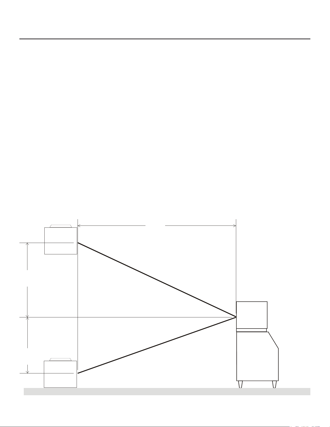
Remote Condenser Location
Use the following for planning the placement of the
condenser relative to the ice machine
Location Limits - condenser location must not exceed
ANY of the following limits:
• Maximum rise from the ice machine to the
condenser is 35 physical feet
• Maximum drop from the ice machine to the
condenser is 15 physical feet
• Physical line set maximum length is 100 feet.
• Calculated line set length maximum is 150.
Calculation Formula:
• Drop = dd x 6.6 (dd = distance in feet)
• Rise = rd x 1.7 (rd = distance in feet)
• Horizontal Run = hd x 1 (hd = distance in feet)
• Calculation: Drop(s) + Rise(s) + Horizontal Run =
dd+rd+hd = Calculated Line Length
Congurations that do NOT meet these requirements
must receive prior written authorization from
Scotsman.
Do NOT:
Route a line set that rises, then falls, then rises.
Route a line set that falls, then rises, then falls.
Calculation Example 1:
The condenser is to be located 5 feet below the ice
machine and then 20 feet away horizontally.
5 feet x 6.6 = 33. 33 + 20 = 53. This location would be
acceptable
Calculation Example 2:
The condenser is to be located 35 feet above and
then 100 feet away horizontally. 35 x 1.7 = 59.5.
59.5 +100 = 159.5. 159.5 is greater than the 150
maximum and is NOT acceptable.
Operating a machine with an unacceptable
conguration is misuse and will void the warranty.
22.87"
17.15"
40.35"
dd
hd
rd
Remote Condenser Located
ABOVE Ice Machine
Remote Condenser Located
BELOW Ice Machine
Max 35’
Max 15’
Condenser Distance &
Location Schematic
June 2022
Page 9
MC0530 through MC1030
Remote Cooled User Manual
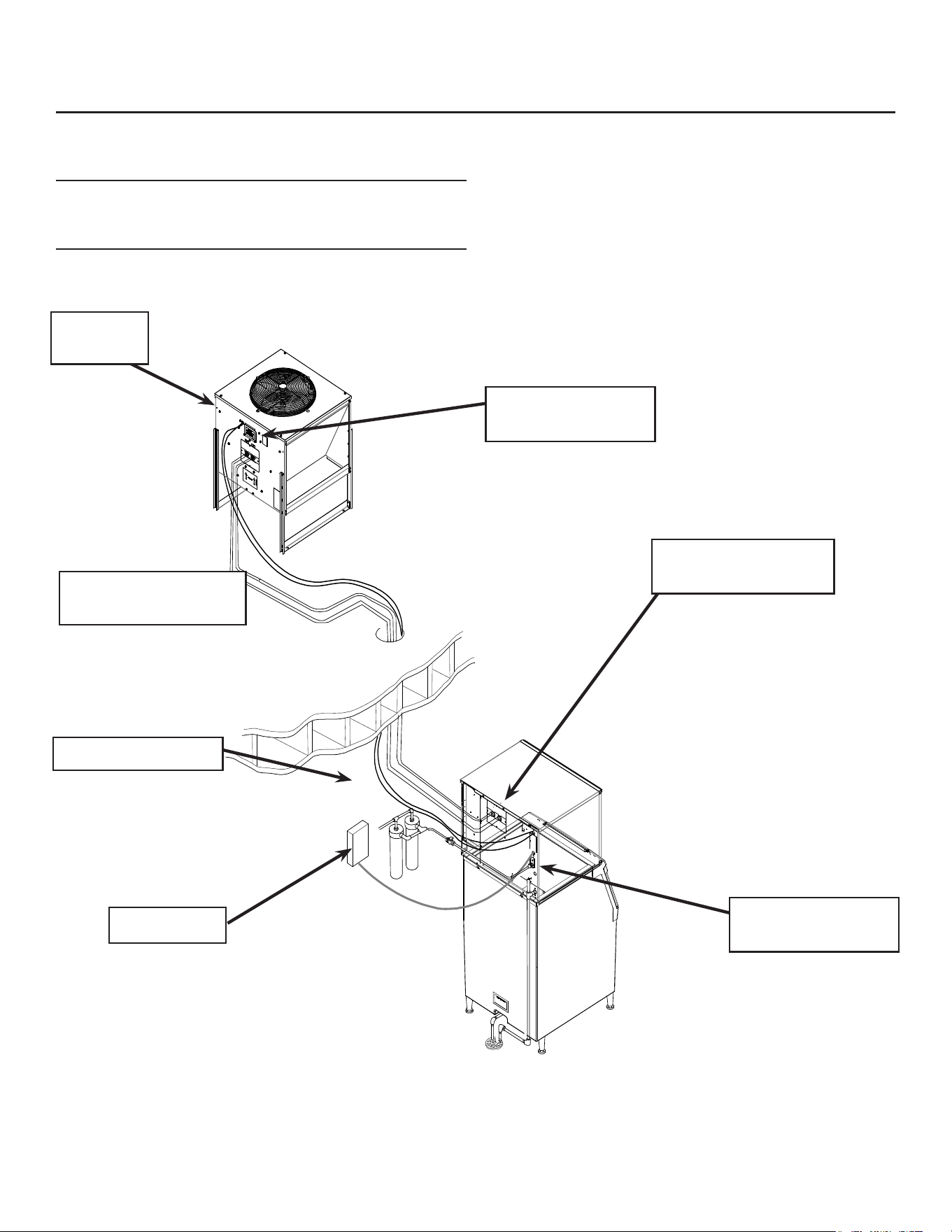
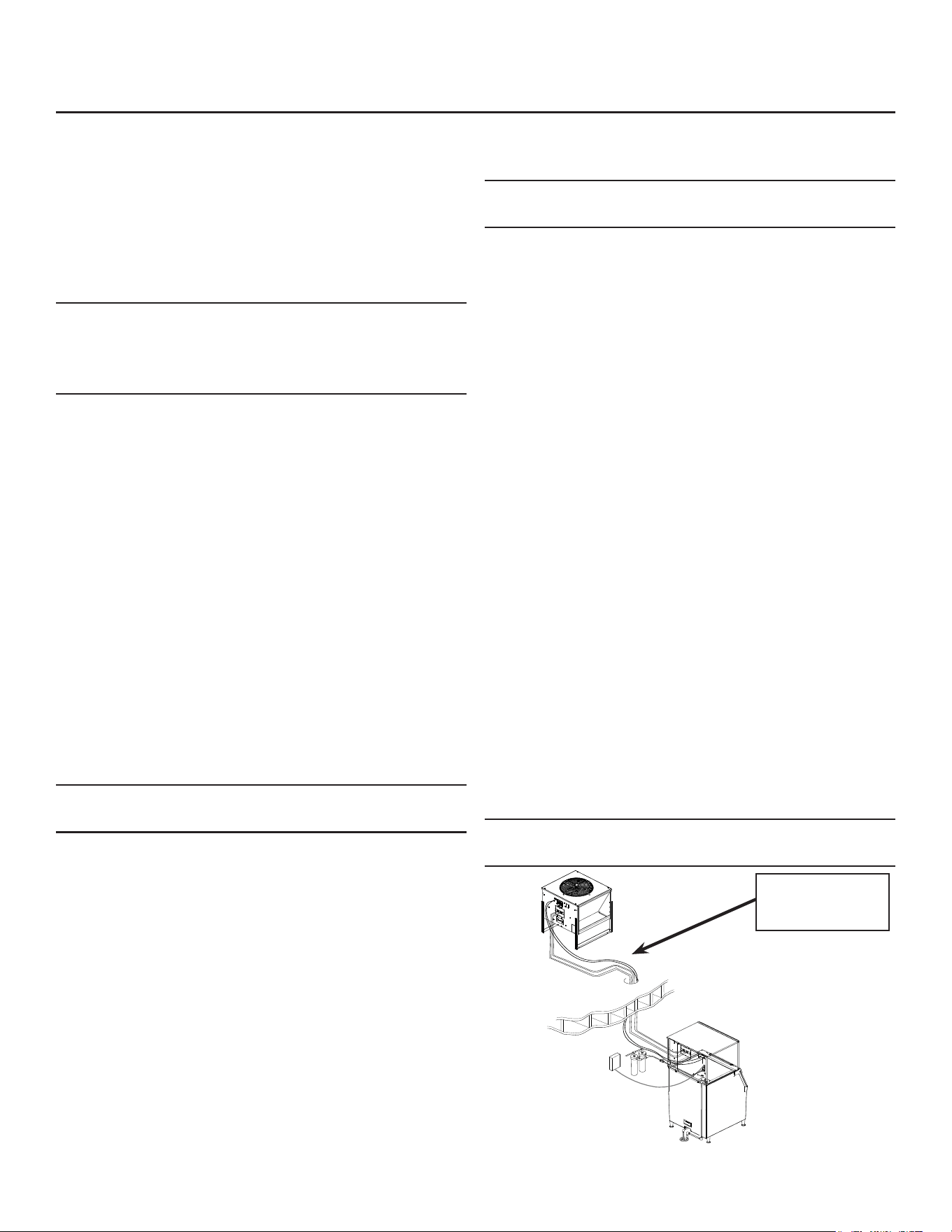
For The Installer: Remote Condenser
Locate the condenser as near as possible to the
interior location of the ice machine.
Note: The location of the condenser is relative to the
ice machine is LIMITED by the specication on the
prior page.
Meet all applicable building codes.
Roof Attachment
Install and attach the remote condenser to the roof
of the building, using the methods and practices of
construction that conform to the local building codes,
including having a roong contractor secure the
condenser to the roof.
Remote Condenser
Electrical Connection
Remote Condenser
Refrigerant Connections
Remote
Condenser
Ice Machine Refrigerant
Connection
Ice Machine Electrical
Connection
Interconnecting Wire
Power Supply
Typical System Installation
June 2022
Page 10
MC0530 through MC1030
Remote Cooled User Manual
Line Set Routing and Brazing
Do not connect the refrigerant tubing until all
routing and forming of the tubing is complete.
Final connections requires brazing, steps must
be performed by an EPA certied type II or higher
technician.
The Lineset of tubing contains a 3/8” diameter liquid
line, and a 1/2” diameter discharge line.
Note: The openings in the building ceiling or wall,
listed in the next step, are the minimum sizes
recommended for passing the refrigerant lines
through.
2. Have the roong contractor cut a minimum hole for
the refrigerant lines of 1 3/4”. Check local codes, a
separate hole may be required for the electrical power
supply to the condenser.
Caution: Do NOT kink the refrigerant tubing while
routing it.
At Condenser:
1. Remove protective plugs from both connections
and vent the nitrogen from the condenser.
2. Remove the tubing access bracket to allow more
room for brazing.
3. Route the lineset tubes to there connection.
4. Clean tubing ends and position into stubs.
Note: Be sure tube and stubs are round, dress with
swage tool if needed.
At Head:
1. Remove the tubing access bracket to allow more
room for brazing.
1. Conrm connection ball valves are fully closed.
2. Remove protective plugs from both connections.
3. Remove caps from access valve connections.
4. Remove cores from access valves.
5. Connect refrigeration hoses to access valves.
6. Connect dry nitrogen source to liquid line
connection.
7. Shorten tubing to correct length, clean ends and
insert them into valve stubs.
Note: Be sure tube and stubs are round, dress with
swage tool if needed.
8. Add heat sink material to ball valve body.
9. Open nitrogen and ow 1 psi nitrogen into liquid
line tube and braze the liquid line and suction line
tubes to the valve stubs.
10. With nitrogen owing braze the liquid and suction
line connections.
At Condenser:
1. Braze the liquid and suction line connections.
At Head:
1. Remove nitrogen source.
2. Return valve cores to access valves.
3. Connect vacuum pump to both access valves and
evacuate the tubing and head to at least a 300
micron level.
4. Remove vacuum pump and add R-404A to both
tubes to provide a positive pressure.
5. Leak check the all braze connections and repair
any leaks.
6. Open both valves to full open.
Note: The full refrigerant charge is contained in the
receiver of the ice machine.
Minimize
Outdoor Tubing
June 2022
Page 11
MC0530 through MC1030
Remote Cooled User Manual
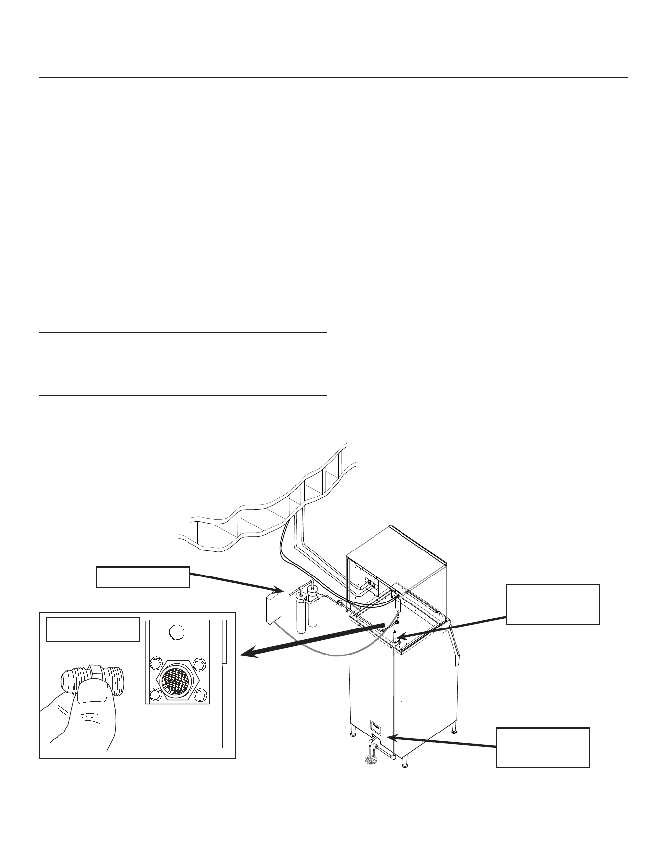
Plumbing Requirements
All models require connection to cold, potable water.
A hand actuated valve within site of the machine
is required. There is a single 3/8” FPT inlet water
connection.
Water Filters Install a new cartridge if the lters were
used with a prior machine.
All models require drain tubing to be attached to them.
There is a single ¾” FPT drain tting in the back of the
cabinet.
Install new tubing when replacing a prior ice machine,
as the tubing will have been sized for the old model
and might not be correct for this one.
1. Connect water supply to water inlet tting.
Note: This NSF listed model has a 1" anti-back ow
air gap between the potable water inlet tube end and
the highest possible reservoir water level, no back
ow device is required.
2. Connect drain tubing to drain tting.
3. Route the drain tubing to building drain. Follow
local codes for drain air gap.
Use rigid drain tubes and route them separately – do
not Tee into the bin’s drain.
Vent the reservoir drain. A vertical vent at the back of
the drain, extended about 8 – 10” will allow the
gravity drain to empty and also keep any surges
during draining from discharging water.
Horizontal runs of drain tubing need a ¼” per fall per
foot of run for proper draining.
Follow all applicable codes.
Water Fitting
Water Supply
Drain Must Be
Vented
Drains Must Be
Separate
Field Supplied
Water Supply and Drain Illustration
June 2022
Page 12
MC0530 through MC1030
Remote Cooled User Manual
Electrical
The machine is not supplied with a power cord, one
must either be eld installed or the machine hard-
wired.
The dataplate on the back of the cabinet details
the power requirements, including voltage, phase,
minimum circuit ampacity and maximum fuse size.
HACR type circuit breakers may be used in place of
fuses. Extension cords are not permitted. Use of a
licensed electrician is recommended.
The ice maker is designed to operate on its own
electrical circuit and must be individually fused.
Voltage variation must not exceed the limits listed
earlier.
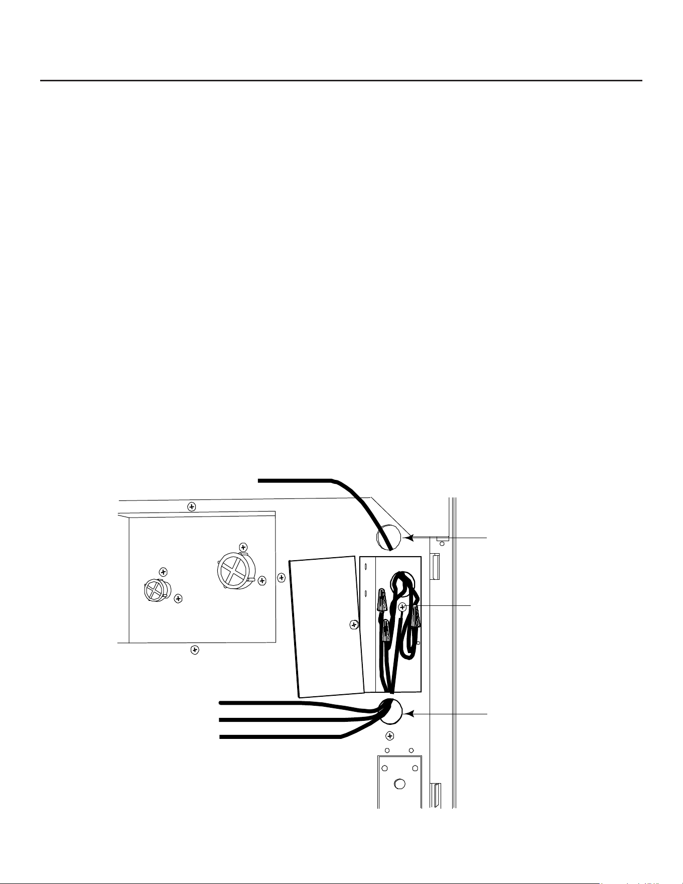
The remote condenser is designed to be powered
from the ice machine. A separate knockout hole has
been provided in the ice maker electrical junction box.
Electrical connections are made inside the junction
box in the back panel of the ice machine.
1. Remove the junction box cover and route the
power cord through the access hole and properly
attach the power supply wires to the leads in the
junction box.
2. Attach the remote condenser fan motor wires to
the wires in the junction box tagged “fan motor
leads”.
3. Install eld supplied strain reliefs per code.
4. Attach a ground wire to the ground connection in
the junction box.
5. Check voltage when complete.
6. Return the junction box cover to its original
position and secure with the original screws.
Follow all applicable local, state and national
codes.
T
o Remote
Condenser
Fan Motor
Junction
Box
Cover
Power
Supply
Wires
Ground
Wire
Connection
Install
Strain
Relief
Install
Strain
Relief
Electrical Connection Detail
June 2022
Page 13
MC0530 through MC1030
Remote Cooled User Manual
Final Check List:
1. Is the unit located indoors in a controlled
environment?
2. Is the unit located where it can receive adequate
cooling air?
3. Has the correct electrical power been supplied to
the machine?
4. Have all the water supply connections been
made?
5. Have all the drain connections been made?
6. Has the remote condenser been properly
installed?
7. Has the interconnecting tubing been properly
routed between the remote condenser and the ice
machine?
8. Have the lines been properly connected and
checked for leaks?
9. Has the power supply wire from the ice machine
to the remote condenser been properly run and
connected?
10. Has the unit been leveled?
11. Have all unpacking materials been removed?
12. Is the water pressure adequate?
13. Have the drain connections been checked for
leaks?
14. Has the bin interior been wiped clean or sanitized?
15. Have any water lter cartridges been replaced?
16. Have all required kits and adapters been properly
installed?
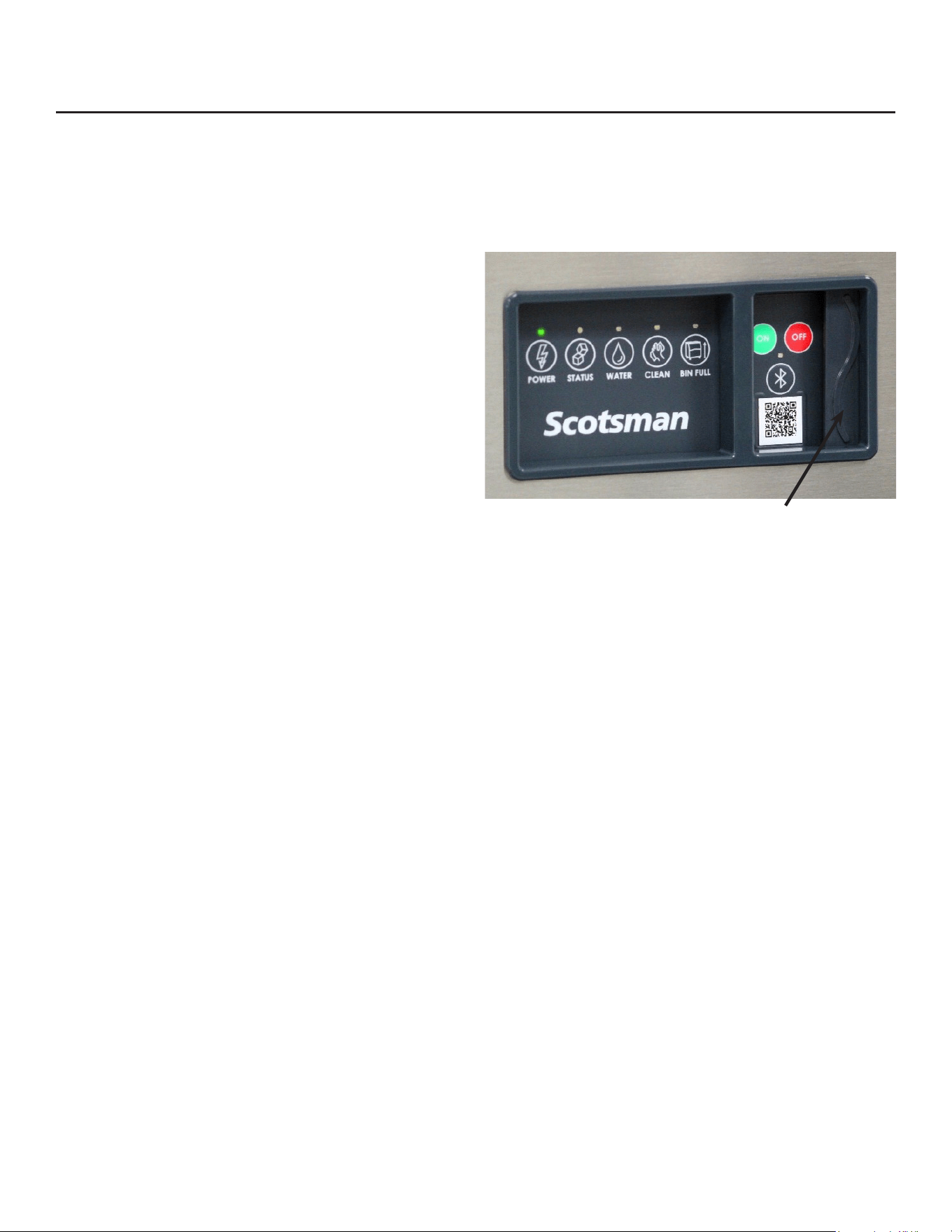
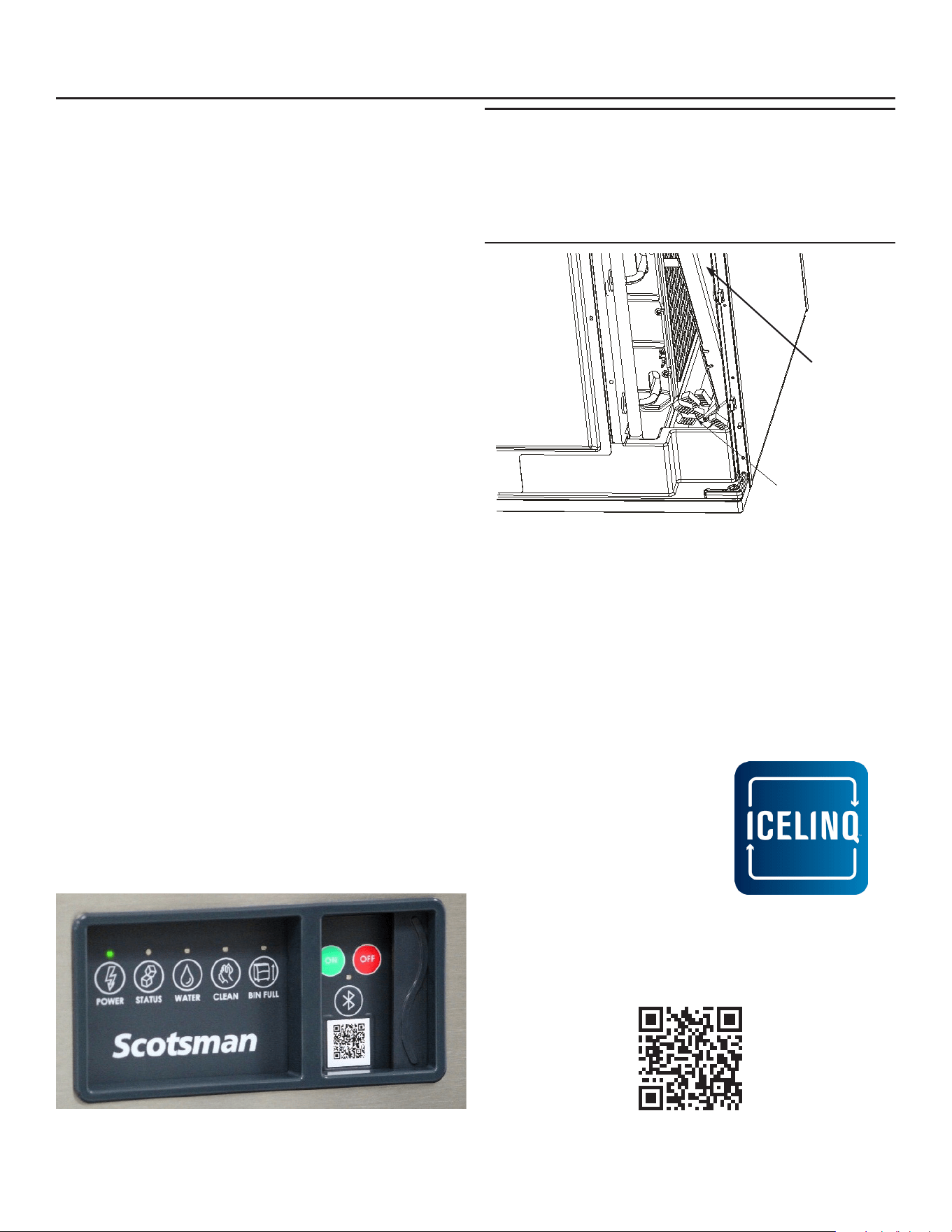
Lower Light and Switch Panel
This user accessible panel provides important
operational information and duplicates the lights and
switches on the controller. It also allows access to the
On and O buttons that operate the ice machine.
Sometimes access to the switches should be limited
to prevent unauthorized operation. For that purpose a
xed panel is shipped in the hardware package. The
xed panel cannot be opened.
To install the xed panel:
1. Remove the front panel.
2. From the back side of the panel, slide the door
to left while spreading the clips to remove the
original door from the bezel.
3. Slide the xed panel into bezel until it snaps into
place.
4. Reinstall front panel.
Open door to access On
and O switch buttons.
June 2022
Page 14
MC0530 through MC1030
Remote Cooled User Manual
Initial Start Up
1. Remove front and left side panels. Check machine
for any packing or wires rubbing moving parts.
Note location of control board in upper left corner
of the machine’s front.
2. Switch on the electrical power to the machine.
Observe that some of the control’s indicator lights
glow and its display shows O.
3. Wait 4 hours for the compressor’s crankcase
heater to warm up the oil in the compressor.
Start Up
1. Open the water supply valve.
2. Turn the receiver’s outlet valve to the full open
position.
3. Push and release the lower ON button.
The indicator light will begin to blink F. The purge
valve will open and the water pump will start. The inlet
water valve will open to add water to the reservoir.
After a few seconds the purge valve will close and
the water pump will stop. Water will ow into the
machine until the reservoir is full. The hot gas valve
and harvest assist device will activate and the liquid
line solenoid valve will open, then the compressor
and water pump will start. The display will show a
continuous F. Five seconds later the hot gas valve will
close and the harvest assist device will return to its
standby position. Warm air will be discharged from the
condenser coil.
4. During the Freeze cycle move the curtain and
observe that the SW1 or SW2 light on the control
board blinks On when the curtain moves away
from the evaporator and O when returned to its
normal position.
Note: Moving the curtain during the Freeze cycle has
no aect on control function, but will cause water to
ow into the cube chute.
5. Observe the Ready for Harvest indicator light. It
may blink early in the freeze cycle, that is normal.
The control will ignore that signal for the rst 6
minutes of freeze.
6. When the ice has frozen enough, the Ready for
Harvest indicator light will be on steady. After it’s
been on steady for a few seconds Harvest will
begin.
7. The display shows an H.
The hot gas valve opens and the harvest assist
mechanism is activated. The purge valve opens to
drain some water, when it does the inlet water valve
opens to rell the reservoir. After a few seconds the
purge valve closes but the inlet water valve continues
to ll the reservoir. Harvest continues until the ice
is released as a unit and forces the curtain to open.
When the curtain opens it signals the controller which
returns the unit to a freeze cycle.
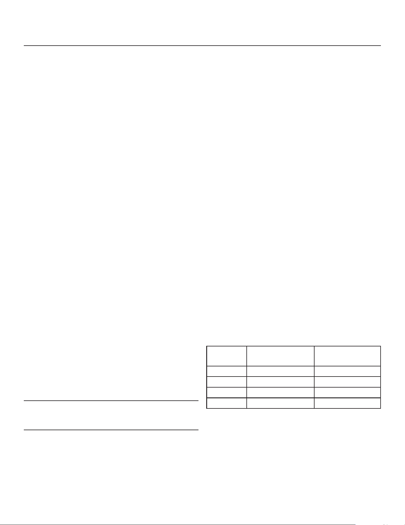
8. Check the ice harvested for proper bridge
thickness. The ice bridge is factory set at 1/8 inch.
If needed, adjust bridge thickness. Do NOT make
it too thin.
9. Return the panels to their normal positions and
secure them to the machine.
10. Instruct the user in the operation of the machine
and its maintenance requirements.
11. Fill out and mail the warranty registration form.
Typical Cycle Times (minutes)
Listed times are for clean machines. Cycle times at
startup will be longer until the system stabilizes.
Model 70
o
F. cond air /
50
o
F. water
90
o
F. cond air /
70
o
F. water
MC0530R 12-14 13-15
MC0630R 8-10 9-11
MC0830R 10-12 11-13
MC1030R 10-12 1 2-14
June 2022
Page 15
MC0530 through MC1030
Remote Cooled User Manual
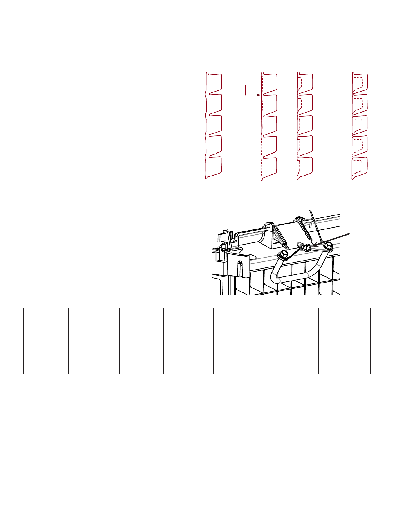
Adjustments
Bridge Thickness - For the Service Tech Only
1. Push and hold O till the machine stops.
2. Remove evaporator cover.
3. Remove curtain.
4. Use a hex wrench and rotate the bridge thickness
adjustment screw in 1/8” turn increments CW to
increase bridge thickness.
5. Rotate CCW to decrease bridge thickness.
Caution: Do not make the bridge too thin or the
machine will not harvest properly. Bridge thickness
adjustments are not covered by warranty.
6. Return curtain and evaporator cover to their
normal positions.
7. Push and release the On button. Check next
harvest of ice. Repeat steps 1-6 if needed.
Water Purge Setting
The water purge is factory set to the automatic
position, suitable for most water conditions. The
setting can be changed to one of 5 manual settings or
left on automatic.
Purge setting 1 - Minimum 2 - Moderate 3 - Standard 4 - Heavy 5 - Maximum A - Automatic
Water Type RO water or
equivalent
Low TDS
non - RO
water
Use for typical
water
High TDS
water
Very High TDS
water
Any with
conductivity not
less than 10
microSiemens/
cm
To set:
1. Switch the machine OFF by holding the O button
in until a number or the letter A shows on the
display.
2. Press and release the On button repeatedly until
the number on the display corresponds to the
desired setting.
3. Press and release the O switch again to return to
the normal control state.
Bridge Thickness Adjustment Mechanism
Note: Indentations may be deeper on MC0322 and MC0330
Ice Bridge Thickness Measurement
Adjustment
Screw
1/8-3/16”
bridge
Too Big
Just Right
Too Small
June 2022
Page 16
MC0530 through MC1030
Remote Cooled User Manual
Use and Operation
Once started, the ice machine will automatically make
ice until the bin or dispenser is full of ice.
When ice level drops, the ice machine will resume
making ice.
Caution: Do not place anything on top of the ice
machine, including the ice scoop. Debris and moisture
from objects on top of the machine can work their way
into the cabinet and cause serious damage. Damage
caused by foreign material is not covered by warranty.
There are four indicator lights at the front of the
machine that provide information on the condition of
the machine.
Indicator Lights:
• Power
• Status
• Water
• De-Scale & Sanitize
Indicator Lights & Their Meanings
Power Status Water De-Scale & Sanitize Bin Full
Steady
Green
Normal Normal – bin full or
making ice
- - Bin is full
Blinking
Green
Self Test
Failure
Switching on or o - -
Blinking
Red
- Diagnostic shutdown or, if
making ice, temperature
sensor failure
Lack of water -
Yellow - - - Time to de-scale and
sanitize
Blinking
Yellow
- - - Preservation Mode is
active or clean cycle is
in progress
Light o No power Switched o Normal Normal Bin is not
full
If the Water light is on, the machine has sensed a
lack of water. Check the water supply to the machine.
The water may have been shut o or the water lter
cartridges need to be changed.
If the De-Scale light is on, the machine has
determined that it may need to be cleaned. Contact
an authorized Scotsman service agent and have the
machine cleaned, de-scaled and sanitized.
During normal operation, if the Clean light begins to
blink yellow, the machine in Preservation mode, which
initiates a timed freeze in response to short freeze
errors. Contact an authorized Scotsman service agent
to service the machine immediately. It is likely that
the machine needs to be cleaned (de-scaled and
sanitized), but may need additional service.
Note: A Component Indicator Light switches ON to
indicate that the component is operating.
Note: There are two Curtain Switch lights, SW1 and
SW2. These single plate models have one curtain
switch light on all the time (either one), as a curtain
switch light is ON when a curtain is either open or not
present.

June 2022
Page 17
MC0530 through MC1030
Remote Cooled User Manual
Control Switches
The On and O switch buttons are front accessible.
To switch the machine OFF, push and release the O
button. The machine will shut o at the end of the next
cycle. To shut the machine o immediately, push and
hold the O button for 3 seconds.
To switch the machine ON, push and release the
On button. The machine will go through a start up
process and then resume ice making.
Control Options
There are two optional, eld installed controls that can
be added to this machine.
• Vari-Smart™ adjustable ice level control
• Smart-Board™ advanced control board and data
logger
Adjustable ice level control
When this option is present there is an adjustment
post and an additional indicator light to the right
of the controller switches. The ultrasonic ice level
control allows the user to control the point that the
ice machine will stop making ice before the bin or
dispenser is full. Reasons for this include:
• Seasonal changes in ice used
• Planning to sanitize the bin
• Faster turnover for fresher ice
• Certain dispenser applications where maximum
ice level is not desired
Note: Ice will build up in the bin or dispenser at an
angle, the distance set will be from the sensor to the
top of the ice. The sensor position is shown in the
cabinet layout diagrams.
The actual distance between the highest point of the
ice may be closer or further away than the distance
set, depending upon the angle of the ice.
Use of control
There are several positions the ice level can be set to,
including O or Max (knob and label indicators lined
up), where it lls the bin until the standard bin control
shuts the machine o. See the kit’s instructions for
complete details.
Rotate the adjustment post to the desired ice level.
The machine will ll up to that level and when it shuts
o the Bin Full indicator light will be On.
Ice
The cuber drops ice in large sections. That ice will
break up into random parts as it falls into the bin, but
some large sections may remain on top of the ice
in the bin. In a dispenser, this ice will break up into
mostly individual cubes as the dispense mechanism
moves the ice. The ice in the bin will normally slope
down from the right to the left.
Heat
When making ice, air-cooled models will discharge
hot air out the back of the cabinet.
Noise
The ice machine will make noise when it is in ice
making mode. The compressor, fan motor(s) if air
cooled, and water pump all produce some sound. It
is also normal to hear some cracking just before the
harvest cycle begins. In addition, during the harvest
cycle the harvest mechanism may click twice as it
pushes the ice out and returns to its normal position.
The ice harvests as a unit or slab, which makes some
noise when it impacts the bin or dispenser. These
noises are all normal for this machine.
POWER STATUS WATER CLEAN
ICE PRODUCTION
MANUAL
HARVEST
INITIATE
CLEAN
OPTIONAL KVS PLACED HERE
(Vari-Smart
TM
Adjustable Ice Level Control)
The following codes will be displayed when
unit is operating as expected:
F
- Freeze
H
- Harvest
B
- Bin Full
O
- Standby/Off
Additional operational and error codes can
be found on the inside of the front panel.
Scan QR code to download the Scotsman ICELINQ™ App:
Connect to this machine via Bluetooth to access additional machine operations,
view error information, adjust settings, and initiate self-guided cleaning.
ON OFF
02-5166-01
OPTIONAL KSBU, KPAS, KSBU-N PLACED HERE
(Smart-Board™ Advanced Control Panel)
Component Operation Indicator Lights
June 2022
Page 18
MC0530 through MC1030
Remote Cooled User Manual
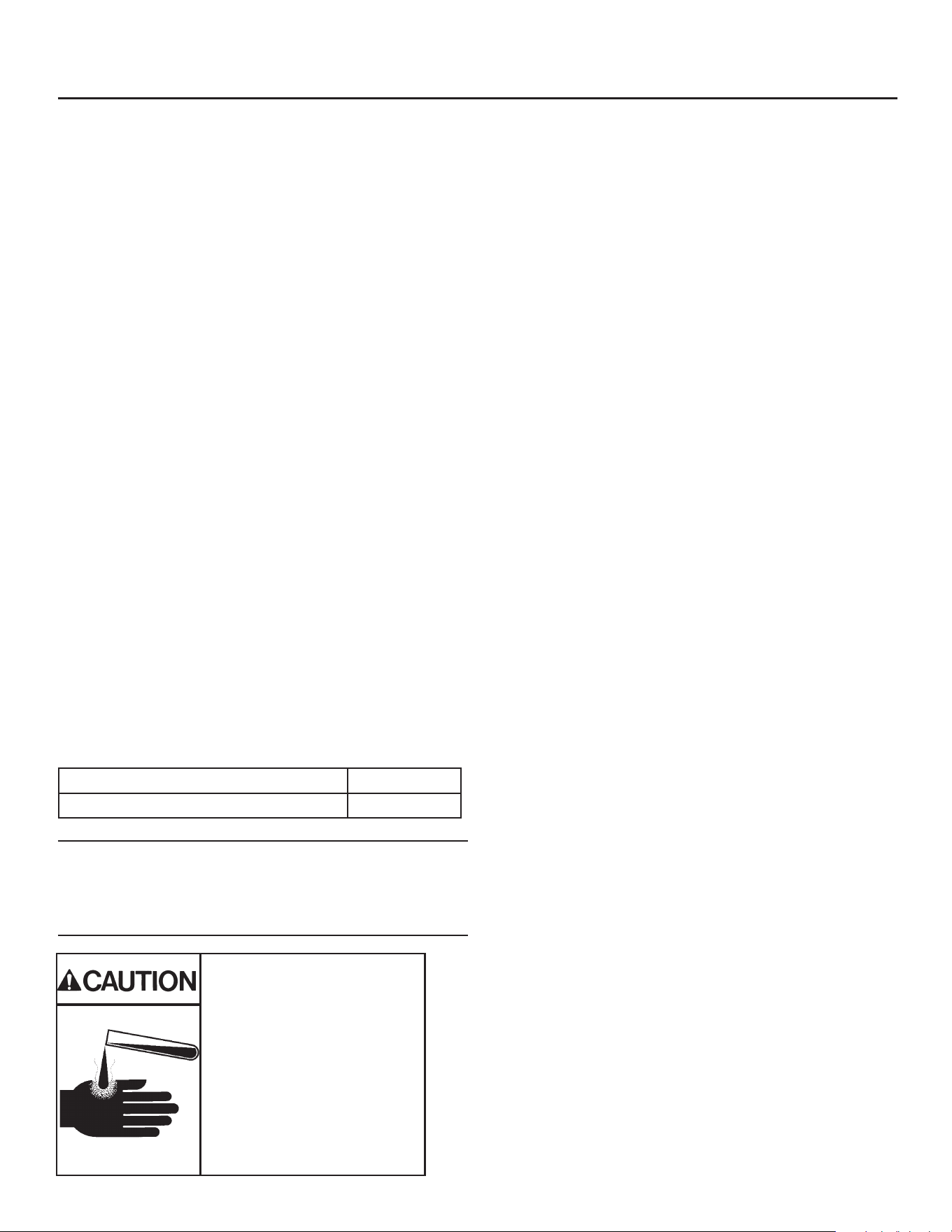
Ice machine cleaner contains
acids. Acids can cause burns.
If concentrated cleaner comes
in contact with skin, ush with
water. If swallowed, do NOT
induce vomiting. Give large
amounts of water or milk. Call
Physician immediately. Keep
out of the reach of children.
Cleaning, Sanitation and Maintenance
This ice system requires three types of maintenance:
• Remove the build up of mineral scale from the ice machine’s water system and sensors.
• Sanitize the ice machine’s water system and the ice storage bin or dispenser.
• Clean condenser
It is the User’s responsibility to keep the ice machine and ice storage bin in a sanitary condition. Without
human intervention, sanitation will not be maintained. Ice machines also require occasional cleaning of their
water systems with a specically designed chemical. This chemical dissolves mineral build up that forms during
the ice making process.
The ice machine’s water system should be cleaned and sanitized a minimum of twice per year. Sanitize the
ice storage bin as frequently as local health codes require, and every time the ice machine is cleaned and
sanitized.
Preparing to Clean:
1. Remove the front panel.
2. Remove the evaporator cover.
Scale Removal:
3. Push and release the Clean button. The yellow
Clean light will blink and the display will show C.
The machine will harvest any ice, drain the reservoir
and begin to rell it.
4. Observe code display, when it blinks the characters
“A d 1” immediately go to the next step.
5. Pour the below specied amount Scotsman Clear
1 ice machine scale remover into the reservoir. The
unit will circulate the scale remover, then drain and
ush it. This will take 35 minutes, then the machine
will stop and the display will show O.
Note: Using chemicals or dilution ratios other than
what is specied will damage the ice machine and
signicantly aect the performance and life of the ice
machine.
Clean internal parts:
6. Mix a cleaning solution of 6oz of Scotsman Clear
1 scale remover with 9 cups (72oz) of 105-115° F
potable water.
7. In a separate bucket, mix a sanitizing solution of 1.6
oz of Nu-Calgon IMS Sanitizer with 1 gallon (128
oz) of 105-115 degree F. potable water.
8. Remove air lter(s)(if applicable), water level sensor
and housing, water distributor(s), curtain(s), ice
thickness sensor, and splash panel for additional
cleaning.
9. Soak and scrub each part (including the
evaporator cover!) using the previously prepared
solution of Scotsman Clear 1 scale remover and a
nylon brush, and then rinse with water. Save scale
remover solution.
10. Soak and scrub each part using the previously
prepared sanitizing solution. No rinse needed. Save
sanitizing solution.
11. Using a non-metallic scouring pad, scrub spillway
with sanitizer to remove any material buildup and
debris.
12. Reinstall ice thickness sensor, curtain(s), splash
panel, water distributor(s), and water level sensor in
their original positions. Be sure water level sensor
and ice thickness sensor are completely dry.
MC0530 or MC0630 10 ounces
MC0722, MC0830 or MC1030 12 ounces
June 2022
Page 19
MC0530 through MC1030
Remote Cooled User Manual
Cleaning, Sanitation and Maintenance Continued
Sanitize:
13. Push and release the Clean button. The yellow
Clean light will blink and the display will show C.
The machine will go through a harvest cycle, drain
the reservoir and begin to rell it.
14. Observe code display, when it blinks the
characters “A d 1” immediately go to the next
step.
15. Pour the previously prepared sanitizing solution
into the reservoir until it is full. The unit will circulate
the sanitizer, then drain and ush it. This will take
35 minutes, then the machine will stop and the
display will show O.
16. Remove all ice from storage bin or dispenser and
sanitize bin or dispenser with remaining sanitizing
solution while machine completes sanitizing cycle.
Pour excess sanitizer down drain.
Finish Cleaning Process:
17. Reinstall evaporator cover and front panel (with
air lter(s) if applicable) in their original positions.
18. Push and release the “ON” button to resume ice
making.
Want more detail?
Scan QR Code to download the Scotsman IcelinQ™
App to connect to this machine via Bluetooth and
access the self-guided cleaning process.
Additional maintenance:
Remote Condenser
The condenser ns will need to be cleaned.
Push and release the O button. Wait until the
machine stops.
Note: Lock out the controller or the ice machine power
supply to prevent an unauthorized fan motor restart.
If there is imbedded grease, use a commercial coil
cleaner to wash out the grease. Dust can be blown
out with compressed air from the inside or use a
vacuum cleaner and soft brush. Be careful not to
damage the condenser’s ns. Use a n comb to
straighten any bent ns.
Exterior Panels
Fingerprints, dust and grease will require cleaning
with a good quality stainless steel cleaner.
Water lters
If the machine has been connected to water lters,
check the cartridges for the date they were replaced
or for the pressure on the gauge. Change cartridges
if they’ve been installed more than 6 months or if the
pressure drops too much when the ice machine lls
with water
Clean
Condenser
Fins
June 2022
Page 20
MC0530 through MC1030
Remote Cooled User Manual
What to do before calling for service
Reasons the machine might shut itself o:
• Lack of water.
• Freeze cycle takes too long.
• Harvest cycle takes too long.
• High discharge temperature.
• Controller self test failure.
Check the following:
1. Has the water supply to the ice machine or
building been shut o? If yes, the ice machine will
automatically restart within 25 minutes after water
begins to ow to it.
2. Has power been shut o to the ice machine? If
yes, the ice machine will automatically restart
when power is restored.
3. Has someone shut the water o to a water
cooled unit? If yes, after the water supply has
been restored the ice machine may need to be
manually reset.
4. Is the curtain open because some ice is stuck
under it? If so, remove the ice and the machine
should start in a few minutes.
To Manually Reset the machine.
• Open the switch door
• Push and release the O button.
• Push and release the On button.
To Shut the Machine O:
1. Push and hold the O button for 3 seconds or until
the machine stops.
2.
Note: Curtain can be removed & replaced anytime the
machine is in a standby mode or when it is in a freeze
cycle. However, removal of the curtain during freeze
will result in water owing into the bin. Removal of the
curtain during harvest terminates harvest at that point
and, if left o, will result in the machine shutting o.
Scotsman ICELINQ® Mobile App
All Prodigy Elite® models are Bluetooth® enabled and
are compatible with the Scotsman ICELINQ® app,
available on both the Apple App Store and Google
Play Store.
The ICELINQ mobile app uses Bluetooth connectivity
to allow users to easily monitor, control, and maintain
their machine:
• View machine status
• Control machine operation
• Adjust machine settings
• View active errors with troubleshooting tips
• Initiate self-guided cleaning
• Access service resources and warranty info
Scan QR Code to download the
Scotsman ICELINQ® App
Curtain
Clear Ice
From Here
Clear Ice From Beneath Curtain
Open Door to Reset or Switch O

17-3737-03 Rev.B
SCOTSMAN ICE SYSTEMS
101 Corporate Woods Parkway
Vernon Hills, IL 60061
www.scotsman-ice.com
800-726-8762