1
Guide Specifications
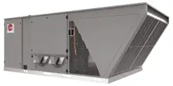
RGEH Series
Guide Specifications RGEH – 180–300
You may copy this document directly into your building specification. This specification is written to comply with the 2004 version of the
“master format” as published by the Construction Specification Institute. www.csinet.org.
GAS HEAT PACKAGED ROOFTOP
HVAC Guide Specifications
Size Range: 15 to 25 Nominal Tons
1.00 General:
A. Outdoor, rooftop mounted, electrically controlled, heating and cooling unit utilizing a(n) hermetic scroll compressor(s) for
cooling duty and heat pump for heating duty.
B. Factory assembled, single-piece heating and cooling rooftop unit. Contained within the unit enclosure shall be all factory
wiring, piping, controls, and special features required prior to field start-up.
C. Unit shall use environmentally safe, R-454B refrigerant.
D. Unit shall be installed in accordance with the manufacturer’s instructions.
E. Unit must be selected and installed in compliance with local, state, and federal codes.
F. Model and serial data shall be printed inside the control box.
1.01 Quality Assurance:
A. Unit meets ASHRAE 90.1 2022 minimum efficiency requirements.
B. Unit shall be rated in accordance with AHRI Standards 340/360.
C. Unit shall be designed to conform to ASHRAE 15.
D. Unit shall be UL-tested and certified in accordance with Standards and UL-listed and certified under Canadian standards as
a total package for safety requirements.
E. Insulation and adhesive shall meet NFPA 90A requirements for flame spread and smoke generation.
F. Unit casing shall be capable of withstanding 500-hour salt spray exposure per ASTM B117 (scribed specimen).
G. Roof curb shall be designed to conform to NRCA Standards.
H. Unit shall be subjected to a completely automated run test on the assembly line. The data for each unit will be stored at the
factory and must be available upon request.
I. Unit shall be designed in accordance with UL Standard 60335-2-40 4th Edition. including tested to withstand rain.
J. Unit shall be constructed to prevent intrusion of snow and tested to prevent snow intrusion into the control box
up to 40 mph.
1.02 Manufacturer Qualifications
A. Unit shall be designed in accordance with ISO 9001:2015 and shall be manufactured in a facility registered by
ISO 9001:2015.
1.03 Installer Qualifications
A. The installer shall be trained to install and service equipment with A2L refrigerants.
1.04 Delivery, Storage, and Handling:
A. Unit shall be stored and handled per manufacturer’s recommendations.
B. Lifted by crane requires either shipping top panel or spreader bars.
C. Unit shall only be stored or positioned in the upright position.
1.05 Unit Cabinet:
A. Unit cabinet shall be constructed of galvanized steel and shall be coated with a baked enamel finish on all externally
exposed surfaces.
B. Unit cabinet exterior paint shall be: pre-painted steel with film thickness, (dry) 0.003 inches minimum, gloss
(per ASTM D523, 60ºF): 60, Hardness: H-2H Pencil hardness.
C. The sheet-metal cabinet shall be constructed of 18-gauge material for structural components with an underlying
coat of G90.
D. Evaporator fan compartment interior cabinet insulation shall conform to AHRI Standards 340/360 minimum exterior sweat
criteria. Interior surfaces shall be insulated with a minimum 3/4-in. thick, 1 lb density, flexible fiberglass insulation, foil faced
on the air side.
E. Shall utilize uniform screw sizing.
F. Base of unit shall have a location for thru-the-base gas and electrical connections standard.
12/25 QG FORM NO. R11-883-GS REV. 1

2
Guide Specifications
RGEH Series
G. Base Rail:
i. Unit shall have base rails on all sides.
ii. Holes shall be provided in the base rails for rigging shackles to facilitate maneuvering and overhead rigging.
iii. Holes shall be provided in the base rail for moving the rooftop for fork truck.
iv. Base rail shall be a minimum of 14 gauge thickness.
H. Condensate pan and connections:
i. Shall be a sloped condensate drain pan made of a non-corrosive material and be removable for cleaning.
ii. Shall comply with ASHRAE Standard 62.
iii. Shall use a 1" – 11 1/2 NPT drain connection through either side of the drain pan. Connection shall be made per
manufacturer’s recommendations.
iv. Shall be able to be easily removed.
v. Shall be separate from the coil.
I. Top panel
i. Shall be a single piece top panel over indoor section.
J. Gas Connections:
i. All gas piping connecting to unit gas valve shall enter the unit cabinet at a single location on side of unit (horizontal
plane).
ii. Thru-the-base capability:
a. Standard unit shall have a thru-the-base gas-line location using a raised, embossed portion of the unit basepan.
b. No basepan penetration, other than those authorized by the manufacturer, is permitted.
K. Electrical Connections:
i. All unit power wiring shall enter unit cabinet at a single, factory-prepared, knockout location.
ii. Thru-the-base capability:
a. Standard unit shall have a thru-the-base electrical location(s) using a raised, embossed portion of the unit
basepan.
b. No basepan penetration, other than those authorized by the manufacturer, is permitted.
L. Component access panels (standard):
i. Cabinet panels shall be easily opened for servicing.
ii. Stainless steel metal hinges are standard on all doors.
iii. Panels covering control box, indoor fan, indoor fan motor, and electric or gas heater components (where applicable),
shall have 1/4 turn latches.
iv. 1/4 fasteners shall be permanently attached.
1.06 Operating Characteristics:
A. Unit shall be capable of starting and running at 115°F (46°C) ambient outdoor temperature, meeting maximum load criteria
of AHRI Standard 340/360 at ± 10% voltage.
B. Compressor with standard controls shall be capable of operation down to 40°F (4°C), ambient outdoor temperatures. Low
ambient accessory kit is necessary if mechanically cooling at ambient temperatures to 40°F (4°C).
C. Unit shall discharge supply air vertically or horizontally as shown on contract drawings.
D. Unit shall be factory configured for vertical supply & return configurations.
E. Unit shall be field convertible from vertical to horizontal configuration.
F. Unit shall be capable of mixed operation: vertical supply with horizontal return or horizontal supply with vertical return.
1.07 Electrical Requirements
A. Main power supply voltage, phase, and frequency must match those required by the manufacturer.
1.08 Evaporator Fan Compartment:
A. Interior cabinet surfaces shall be insulated with a minimum 3/4-in. thick, minimum 1 LB density, flexible fiberglass insulation
bonded with foil face on the air side.
B. Insulation and adhesive shall meet NFPA 90A requirements for flame spread and smoke generation.
C. Insulation shall also be mechanically fastened with welded pin and retainer washer.
1.09 Thermostats
A. Thermostat must:
i. Energize “G” when calling for heat.
ii. Have capability to energize 2 different stages of cooling, and 2 different stages of heating.
iii. Must include capability for occupancy scheduling.
12/25 QG FORM NO. R11-883-GS REV. 1

3
Guide Specifications
RGEH Series
1.10 Electronic Control System for HVAC:
A. Shall be complete with self-contained low-voltage control circuit protected by a fuse on the 24-V transformer side
(090-150 units have a resettable circuit breaker).
B. Shall utilize color-coded wiring.
C. Unit shall include a minimum of one 8-pin screw terminal connection board for connection of control wiring.
D. Unit control board shall be provided with 7 segment readout via LCD display for status and diagnostics.
1.10.01 Safeties:
A. Compressor over-temperature, over current.
B. Standard Low-pressure switch:
i. Units shall have low pressure, loss of charge automatic reset device that will shut off compressor when tripped.
ii. Low pressure control
a. Provides active protection in both heating and cooling modes at all outdoor ambient temperatures.
The low pressure control is an automatic reset type and opens at approximately 95 psig and closes
at approximately 50 psig. Operation is slightly different between cooling and heating modes.
C. Standard High-pressure switch:
i. Unit shall be equipped with high pressure switch device that will shut off compressor when tripped.
ii. High pressure control
a. The high pressure control is an automatic reset type and opens at approximately 610 psig and closes at
approximately 420 psig. The compressor and fan motor will stop when the high pressure control opens and will
start again if the high side pressure drops to approximately 420 psig where the automatic reset high pressure
control resets. If the high pressure control opens 3 times within a particular call for heating or cooling operation,
the defrost control will lock out compressor and outdoor fan operation.
D. Automatic reset, motor thermal overload protector is standard on all models except 25 ton G-drive models.
E. The unit must be permanently grounded.
F. Components are not compatible between different refrigerants. Do not use R-410A service equipment or
components on R-454B equipment. System or part failure could occur.
1.11 Standard Filter Section:
A. Shall consist of factory-installed, low velocity, throwaway 2-in. thick fiberglass filters of commercially available sizes.
B. Unit will accept only 2 inch filters.
C. Filter face velocity shall not exceed 365 fpm at nominal airflows.
D. Filters shall be accessible through an access panel with “no-tool” removal as described in the unit cabinet
section of the specification.
E. Filters shall be held in place by a sliding filter tray, facilitating easy removal and installation.
F. Filters access is specified in the unit cabinet section of this specification.
1.12 Coils:
A. Standard Aluminum/MicroChannel Condenser Coils:
i. Standard evaporator and condenser coils shall be aluminum.
ii. Evaporator and condenser coils shall be leak tested to 150 psig, pressure tested to 400 psig, and
qualified to burst test at 2,200 psi.
B. Standard Aluminum/Copper Evaporator Coils:
i. Standard evaporator and condenser coils shall have aluminum lanced plate fins mechanically bonded to seamless
internally grooved copper tubes with all joints brazed.
ii. Evaporator and Condenser coils shall be leak tested to 150 psig, pressure tested to 550 psig and qualified to
UL 1995 burst test at 2,200 psig.
1.13 Refrigerant Components:
A. Refrigerant circuit shall include the following control, safety, and maintenance features:
i. Thermal Expansion Valve (TXV) with orifice type distributor.
ii. Refrigerant filter drier.
iii. External service gauge connections to unit suction and discharge lines.
iv. Pressure gauge access through an access port in the front and rear panel of the unit.
v. External gauge ports shall be lockable.
B. Compressors:
i. Unit shall use one fully hermetic, scroll compressor for each independent refrigeration circuit.
ii. Compressor motors shall be cooled by refrigerant gas passing through motor windings.
12/25 QG FORM NO. R11-883-GS REV. 1

4
iii. Compressors shall be internally protected from high discharge temperature conditions. Advanced Scroll
Temperature Protection on 240-300 sizes.
iv. Compressors shall be protected from an over-temperature and over-amperage conditions by an internal, motor
overload device.
v. Compressor shall be factory mounted on rubber grommets.
vi. Compressor motors shall have internal line break thermal and current overload protection.
vii. Crankcase heaters shall not be required for normal operating range.
viii. Compressor shall have molded electrical plug.
1.14 Evaporator Fan and Motor:
A. Evaporator fan motor:
i. Shall have permanently lubricated bearings
ii. Shall have inherent automatic-reset thermal overload protection.
iii. Shall have a maximum continuous bhp rating for continuous duty operation; no safety factors above that
rating shall be required.
B. Direct Drive Evaporator Fan:
i. Belt drive shall include an adjustable-pitch motor pulley.
ii. Shall use sealed, permanently lubricated ball-bearing type.
iii. Blower fan shall be double-inlet type with forward-curved blades.
iv. Shall be constructed from steel with a corrosion resistant finish and dynamically balanced.
C. Blower Assembly:
i. Entire assembly shall be able to slide out completely.
ii. Shall be able to slide-out without the removal of the roof and condenser fan motors.
1.15 Condenser Fans and Motors:
A. Condenser fan motors:
i. Shall be a totally enclosed motor.
ii. Shall use permanently lubricated bearings.
iii. Shall have inherent thermal overload protection with an automatic reset feature.
iv. Shall use a shaft-down design. Shaft-up designs including those with “rain-slinger devices” shall not be allowed.
B. Condenser Fans shall:
i. Shall be a direct-driven propeller type fan
ii. Shall have blades riveted to corrosion-resistant steel spiders and shall be dynamically balanced.
1.16 RTU-C Controller:
A. Shall be ASHRAE 62-2001 compliant.
B. Shall accept 18-32VAC input power.
C. Shall have an operating temperature range from -40ºF (-40ºC) to 158ºF (70ºC), 10%– 95% RH (non-condensing).
D. Controller shall accept the following inputs: space temperature, setpoint adjustment, outdoor air temperature, indoor air
quality, outdoor air enthalpy, fire shutdown, return air enthalpy, fan status, remote time clock/door switch.
E. Shall accept a CO2 sensor in the conditioned space and be Demand Control Ventilation (DCV) ready.
F. Shall provide the following outputs: Economizer, fan, cooling stage 1, cooling stage 2, heat stage 1,
heat stage 2, exhaust, occupied.
G. Unit shall provide surge protection for the controller through a circuit breaker.
H. Shall have a field-installed communication card allowing the unit to be able to communicate at a Baud rate of
19.2K or faster.
I. Shall have an LED display independently showing the status of activity on the communication bus, and processor
operation.
J. Optional field-installed BACnet plug-in communication card which includes an EIA-485 protocol communication port,
or an optional field-installed LonWorks plug-in communications card.
K. Software upgrades will be accomplished by local download. Software upgrades through chip replacements are not allowed.
L. Shall be shock resistant in all planes to 5G peak, 11ms during operation, and 100G peak, 11ms during storage.
M. Shall be vibration resistant in all planes to 1.5G @ 20-300 Hz.
N. Shall support a bus length of 4000 ft max, 60 devices per 1000 ft section, and 1 RS-485 repeater per 1000 ft sections.
1.17 Open Protocol, Direct Digital Controller:
A. Shall be ASHRAE 62-2001 compliant.
B. Shall accept 18-30VAC, 50-60Hz, and consumer 15VA or less power.
Guide Specifications
RGEH Series
12/25 QG FORM NO. R11-883-GS REV. 1

5
Guide Specifications
RGEH Series
C. Shall have an operating temperature range from -40ºF (-40ºC) to 130ºF (54ºC), 10% - 90% RH (non-condensing).
D. Shall have either a field-installed BACnet plug-in communication card which includes an EIA-485 protocol communication
port, or a field-installed LonWorks plug-in communications card.
E. The BACnet plug in communication card shall include built-in protocol for BACNET (MS/TP and PTP modes)
F. The LonWorks™ plug in communication card shall include the Echelon processor required for all Lon applications.
G. Shall allow access of up to 62 network variables (SNVT). Shall be compatible with all open controllers
H. Baud rate Controller shall be selectable through the EIA-485 protocol communication port.
I. Shall have an LED display independently showing the status of serial communication, running, errors, power, all digital
outputs, and all analog inputs.
J. Shall accept the following inputs: space temperature, setpoint adjustment, outdoor air temperature, indoor
air quality, outdoor air enthalpy, compressor lock-out, fire shutdown, enthalpy switch, and fan status/filter
status/humidity/remote occupancy.
K. Shall provide the following outputs: economizer, fan, cooling stage 1, cooling stage 2, heat stage 1, heat stage 2, exhaust.
L. Software upgrades will be accomplished by either local or remote download. No software upgrades through chip
replacements are allowed.
M. Shall be natively equipped with Modbus communication protocol.
1.18 Adjustable Frequency Drive:
A. Unit shall be supplied with an electronic variable frequency drive for the supply air fan.
B. Drive shall be factory-installed in an enclosed cabinet.
C. Drive shall meet UL Standard 60335-2-40 4th Edition.
D. The completed unit assembly shall be UL listed.
E. Drives are to be accessible through a tooled access hinged door assembly.
F. The unit manufacturer shall install all power and control wiring.
G. The supply air fan drive output shall be controlled by the factory-installed main unit control system and drive status and
operating speed shall be monitored and displayed at the main unit control panel.
H. Drive shall be programmed, and factory run tested in the unit.
1.19 Gas Heat:
A. Shall have standard two stage gas heat.
B. Heat exchanger shall be an induced draft design. Positive pressure heat exchanger designs shall not be allowed.
C. Shall incorporate a direct-spark ignition system and redundant main gas valve.
D. Heat exchanger design shall allow combustion process condensate to gravity drain; maintenance to drain the gas heat
exchanger shall not be required.
E. Gas supply pressure at the inlet to the rooftop unit gas valve must match that required by the manufacturer.
F. The heat exchanger shall be controlled by the Core Command microprocessor.
i. The Core Command board shall notify users of fault using two 7 segment displays.
G. Standard Heat Exchanger Construction:
i. Heat exchanger shall be of the tubular-section type constructed of a minimum of 20-gauge steel coated with a
nominal 1.2 mil aluminum-silicone alloy for corrosion resistance.
ii. Burners shall be of the in-shot type constructed of aluminum-coated steel.
iii. Burners shall incorporate orifice for rated heat output up to 2,000 ft. (610m) elevation with a gas heating valve of
1050. Alternate orifices may be required depending on local gas heating valves and elevations.
iv. Each heat exchanger tube shall contain restrictions similar to dimples for increased heating effectiveness.
H. Optional Stainless Steel Heat Exchanger Construction:
i. Use energy saving, direct-spark ignition system.
ii. Use a redundant main gas valve.
iii. Burners shall be of the in-shot type constructed of aluminum-coated steel.
iv. All gas piping shall enter the unit cabinet at a single location on side of unit (horizontal plane).
v. The optional stainless steel heat exchanger shall be of the tubular-section type, constructed of a minimum
of 20-gauge type 409 stainless steel.
vi. Type 409 stainless steel shall be used in heat exchanger tubes.
vii. Complete stainless steel heat exchanger allows for greater application flexibility.
a. Induced draft combustion motor and blower
i. Shall be a direct-drive, single inlet, forward-curved centrifugal type.
12/25 QG FORM NO. R11-883-GS REV. 1

6
ii. Shall be made from steel with a corrosion-resistant finish.
iii. Shall be permanently lubricated sealed bearings.
iv. Shall have inherent thermal overload protection.
v. Shall have an automatic reset feature.
1.20 Special Features:
A. Integrated Economizers:
i. Integrated, gear-driven parallel modulating blade design type capable of simultaneous economizer and compressor
operation.
ii. Independent modules for vertical or horizontal return configurations shall be available. Vertical return modules shall
be available as a factory-installed option.
iii. Damper blades shall be galvanized steel with metal gears. Plastic or composite blades on intake or return shall not
be acceptable.
iv. Shall include all hardware and controls to provide free cooling with outdoor air when temperature and/or humidity are
below setpoints.
v. Shall be equipped with gear driven dampers for both the outdoor ventilation air and the return air for positive air
stream control.
vi. Shall be equipped with low-leakage dampers, not to exceed 2% leakage at 1 in. wg pressure differential.
vii. Shall be capable of introducing up to 100% outdoor air.
viii. Shall be equipped with a barometric relief damper capable of relieving up to 100% return air.
ix. Shall be designed to close damper(s) during loss-of-power situations with spring return built into motor.
x. Enthalpy sensor shall be provided as standard. Outdoor air sensor set point shall be adjustable and shall range
enthalpy equivalent of 63°F @ 50% RH to 73°F @ 50% RH. Additional sensor options shall be available as
accessories.
xi. The economizer controller shall also provide control of an accessory power exhaust unit function. Factory set at
70%, with a range of 0% to 100%.
xii. The economizer shall maintain minimum airflow into the building during occupied period and provide design
ventilation rate for full occupancy. A remote potentiometer may be used to override the damper set point.
xiii. Dampers shall be completely closed when the unit is in the unoccupied mode.
xiv. Economizer controller shall accept a 2-10Vdc CO2 sensor input for IAQ/DCV control. In this mode, dampers shall
modulate the outdoor-air damper to provide ventilation based on the sensor input.
xv. Compressor lockout sensor on the unit controller is factory set at 35°F and is adjustable from 30ºF (-1ºC) to 50ºF
(10ºC) and resets the cooling lockout at 5°F (+2.7°C) above the set point.
xvi. Actuator shall be direct coupled to economizer gear. No linkage arms or control rods shall be acceptable.
xvii. Economizer controller shall provide indications when in free cooling mode, in the DCV mode, or the exhaust fan
contact is closed.
xviii. Economizer wire harness will have provision for smoke detector.
xix. Shall provide fault detection and diagnostics (FDD) system in accordance with local code. Faults shall be
communicated out on an alarm signal.
B. Two-Position Motorized Damper:
i. Damper shall be a Two-Position Motorized Damper. Damper travel shall be from the full closed position to the field
adjustable %-open setpoint.
ii. Damper shall include adjustable damper travel from 25% to 100% (full open).
iii. Damper shall include single or dual blade, gear driven dampers and actuator motor.
iv. Actuator shall be direct coupled to damper gear. No linkage arms or control rods shall be acceptable.
v. Damper will admit up to 100% outdoor air for applicable rooftop units.
vi. Damper shall close upon indoor (evaporator) fan shutoff and/or loss of power.
vii. The damper actuator shall plug into the rooftop unit’s wiring harness plug. No hard wiring shall be required.
viii. Outside air hood shall include aluminum water entrainment filter
C. Manual damper
i. Manual damper package shall consist of damper, air inlet screen, and rain hood which can be preset to
admit up to 50% outdoor air for year-round ventilation.
D. Head Pressure Control Package
i. Controller shall control coil head pressure by condenser-fan cycling.
Guide Specifications
RGEH Series
12/25 QG FORM NO. R11-883-GS REV. 1

7
Guide Specifications
RGEH Series
E. Liquid Propane (LP) Conversion Kit
i. Package shall contain all the necessary hardware and instructions to convert a standard natural gas unit
for use with liquefied propane, up to 2000 ft (610m) elevation.
F. Condenser Coil Hail Guard Assembly:
i. Shall protect against damage from hail.
ii. Shall be louvered style.
G. Unit-Mounted, Non-Fused Disconnect Switch:
i. Switch shall be factory-installed, internally mounted.
ii. National Electric Code (NEC) and UL approved non-fused switch shall provide unit power shutoff.
iii. Shall be accessible from outside the unit.
iv. Shall provide local shutdown and lockout capability.
H. Convenience Outlet:
i. Non-Powered convenience outlet.
ii. Outlet shall be powered from a separate 115V-120V power source.
iii. A transformer shall not be included.
iv. Outlet shall be field-installed and internally mounted with easily accessible 115V female receptacle.
v. Outlet shall include 15-amp GFI receptacle with independent fuse protection.
vi. Outlet shall be accessible from outside the unit.
I. Fan/Filter Status Switch:
i. Switch shall provide status of indoor evaporator fan (ON/OFF) or filter (CLEAN/DIRTY).
ii. Status shall be displayed either over communication bus (when used with direct digital controls) or through the
controller LCD display inside the unit control box.
J. Flue Discharge Deflector:
i. Flue discharge deflector shall direct unit exhaust vertically instead of horizontally.
ii. Deflector shall be defined as a “natural draft” device by the National Fuel and Gas (NFG) code.
K. Propeller Power Exhaust:
i. Power exhaust shall be used in conjunction with an integrated economizer.
ii. Independent modules for vertical or horizontal return configurations shall be available.
iii. Horizontal power exhaust shall be mounted in return ductwork.
iv. Power exhaust shall be controlled by economizer controller operation. Exhaust fans shall be energized when
dampers open past the 0-100% adjustable setpoint on the economizer control.
v. Capable of adjustable but constant volume.
L. Dehumidification:
i. Shall utilize a dual-phase hot gas reheat control sequence.
ii. Shall be installed with a thermostat or space temperature sensor and an indoor relative humidity sensor,
which shall connect to the Rooftop Unit Controller (RTU-C).
iii. Shall provide neutral air to the occupied space.
iv. Shall have two modes: Cooling and Dehumidification.
v. In cooling mode, the vapor refrigerant shall remove the heat to the outdoor coil, where heat is released outdoor.
This allows the refrigerant to condense and become a subcooled liquid and the process shall repeat itself.
vi. In dehumidification mode, the refrigerant shall absorb heat via the indoor coil from the cooling area. The heat shall
be carried via a parallel path to then release heat back into the cooling area allowing for the dehumidification.
vii. Modulate reheat coil refrigerant temperature via outdoor fan motor controller to achieve neutral air.
viii. Variable Frequency Drive shall allow the unit to operate with two stages of heat.
M. Roof Curbs (Vertical):
i. Full perimeter roof curb with exhaust capability providing separate air streams for energy recovery from the
exhaust air without supply air contamination.
ii. Formed galvanized steel with wood nailer strip and shall be capable of supporting entire unit weight.
iii. Permits installation and securing of ductwork to curb prior to mounting unit on the curb.
N. High-Static Indoor Fan Motor(s) and Drive(s)
i. High-static motor(s) and drive(s) shall be factory-installed to provide additional performance range.
12/25 QG FORM NO. R11-883-GS REV. 1

8
O. Universal Gas Conversion Kit
i. Package shall contain all the necessary hardware and instructions to convert a standard natural gas unit to operate
from 2000-7000 ft (610 to 2134m) elevation with natural gas or from 0-7000 ft (90-2134m) elevation with liquefied
propane.
P. Outdoor Air Enthalpy Sensor
i. The outdoor air enthalpy sensor shall be used to provide single enthalpy control. When used in conjunction with a
return air enthalpy sensor, the unit will provide differential enthalpy control. The sensor allows the unit to determine if
outside air is suitable for free cooling.
Q. Return Air Enthalpy Sensor
i. The return air enthalpy sensor shall be used in conjunction with an outdoor air enthalpy sensor to provide differential
enthalpy control.
R. Indoor Air Quality (CO2) Sensor:
i. Shall be able to provide demand ventilation indoor air quality (IAQ) control.
ii. The IAQ sensor shall be available in duct mount, wall mount, or wall mount with LED display.
The set point shall have adjustment capability.
S. Smoke detectors:
i. Shall be a Four-Wire Controller and Detector.
ii. Shall be environmentally compensated with differential sensing for reliable, stable, and drift-free sensitivity.
iii. Shall use magnet-activated test/reset sensor switches.
iv. Shall have a recessed momentary switch for testing and resetting the detector.
v. Controller shall include:
a. One set of normally open alarm initiation contacts for connection to an initiating device circuit on a fire alarm
control panel
b. Two Form-C auxiliary alarm relays for interface with rooftop unit or other equipment
c. One Form-C supervision (trouble) relay to control the operation of the Trouble LED on a remote test/reset station
d. Capable of direct connection to two individual detector modules.
e. Can be wired to up to 14 other duct smoke detectors for multiple fan shutdown applications.
T. Barometric relief:
i. Shall include damper, seals, hard-ware, and hoods to relieve excess building pressure.
ii. Damper shall gravity-close upon shutdown.
iii. Only available with an economizer. Barometric relief is not available as a stand-alone accessory
U. Time Guard:
i. Shall prevent compressor short cycling by providing a 5-minute delay (±2 minutes) before restarting a compressor
after shutdown for any reason.
ii. One device shall be required per compressor.
V. Standard Factory-Installed Overflow Switch
i. Switch shall monitor the condensate level in drain pan and stops compression operation when overflow
conditions occur
W. Access Panels:
i. Hinges with ¼ turn fasteners shall be permanently attached.
ii. Hinges shall be powder coated and made from stainless steel.
a. Electric Heat
i. Heating Section:
a. Heater element open coil resistance wire, nickel-chrome alloy, strung through ceramic insulators mounted on
metal frame. Coil ends are staked and welded to terminal screw slots.
b. Heater assemblies are provided with integral fusing for protection of internal heater circuits not exceeding
48 amps each. Auto reset thermostat limit controls, magnetic heater contactors (24V coil) and terminal block all
mounted in electric heater control box (minimum 18 gauge galvanized steel) attached to end of heater assembly.
X. Refrigerant Detection System:
i. In the event of a detected refrigerant leak, the refrigerant leak detection sensor(s) will trigger the mitigation
procedure that shuts off the compressor(s) and turns on the indoor blower motor.
ii. In the event of a detected refrigerant leak, the system will display a fault code on the unitary controller.
For DDC systems, “A2L Event” will appear on the LCD module.
Guide Specifications
RGEH Series
12/25 QG FORM NO. R11-883-GS REV. 1