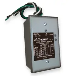

208/230V~60Hz,1Ph
115V~60Hz,1Ph
INSTALLATION/
APPLICATION
MANUAL
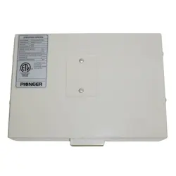
24 Volt Interface Adapter
IMPORTANT NOTE:
Read this manual carefully before installing or operating
your new 24 Volt Interface Adapter. Make sure to save
this manual for future reference.
Makes any Pioneer Quantum Series mini split system
compatible with 24V analog heat pump thermostats!

Preparation Before Installation........................................................................................................1
Installation Method............................................................................................................................ 2
System Conguration......................................................................................................................... 2
Application............................................................................................................................................. 3
Control Logic..........................................................................................................................................9
DIP Switch Denitions......................................................................................................................10
Error Codes............................................................................................................................................11
Wiring Diagram...................................................................................................................................12
Table of Contents
Read this manual carefully before installing or
operating your new air conditioning unit. Make
sure to save this manual for future reference.
Page 1
WARNING
•
Wires must be properly sized according to the
NEC/NFPA 70, CEC and all prevailing codes,
ordinances and standards.
•
•
•
•
•
•
All conductors must be installed with a strain
relief eliminating stress on the wire following
installation which may result in wire damage
and/or overheating with a potential for re.
CAUTION
•
When connecting with RS 485 communication
to the outdoor unit, shielded wire must be used
and grounded at one end only.
When using shielded wire the cable should be
grounded at one end to reduce EMI.
Read this manual carefully before installing or
operating your new air conditioning unit.Make
sure to save this manual for future reference.
Wear appropriate personal protection equipment
(PPE) when installing or servicing.
•
•
T1 sensor cable shall not exceed 23' (7 m).
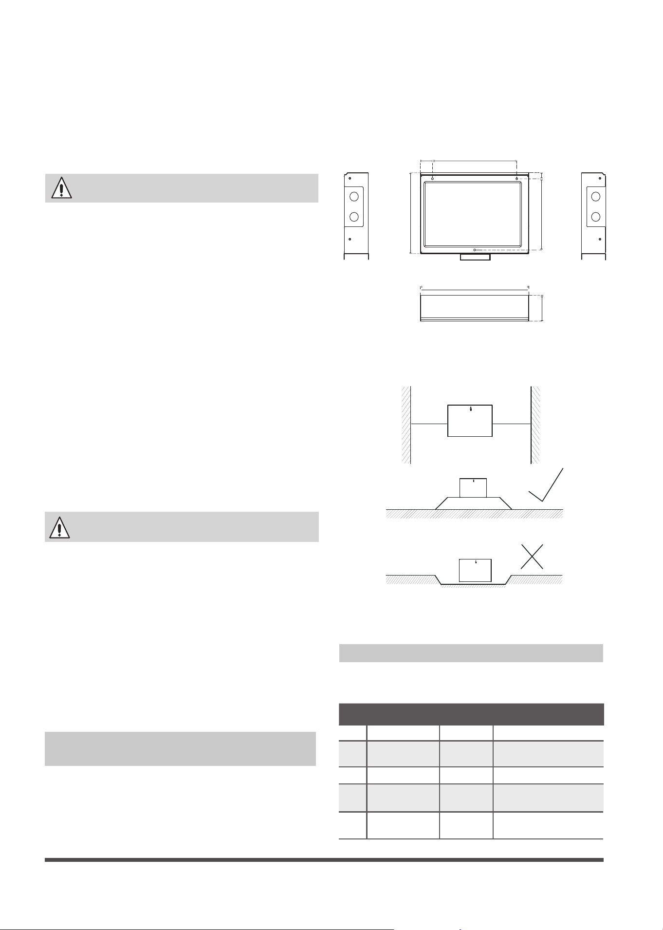
24V INTERFACE KIT Dimensions
220mm
(8.7”)
32mm
(1.3”)
176mm
(6.9”)
15m
m
(0.6”)
200mm
(7.8”)
Fig. 1
283mm
(11.1”)
63mm
(2.5”)
1. Ensure you have the following parts
Table 1
No Name Quantity Remarks
1 Control box 1
2 Screws
3
M4*20 (For mounting
on the wall)
3 Anchors
3
For mounting on the wall
4 The connective
wires group
2
Preparation Before Installation
General installation instructions
Location and clearances
Wall-Mounted 24V INTERFACE KIT
Installation
Installation must be performed in accordance
with the requirement of NEC and CEC by
authorized personnel only.
All wiring to be rated for the control box
amperage rating.
All wiring installed to meet general industry
standards and practices,
Do not install adapter near ammable liquids
or gases.
Do not operate the unit with wet hands, as
this could lead to electrical shock.
For connecting the sensor
5
5m connective
wires group
1
>150mm
>150mm
This interface must be installed indoors in an
area free from drips and moisture.
Right
Wrong
Page 2
System Conguration
NOTE:
Thermostat should be congured for
use with a conventional system.
The remote controller,wiring controller,
central controller and WiFi can not be used
with this control box at the same time.Only
the Swing and LED fucation can be used.
•
•
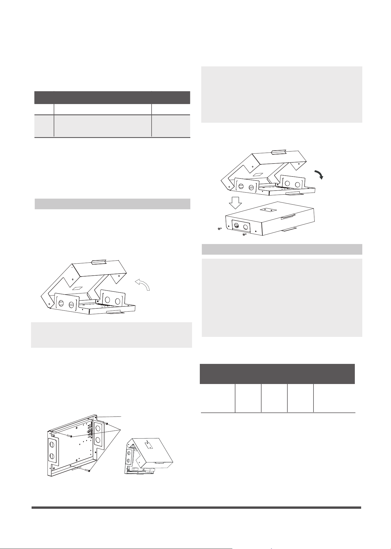
4. Cover the 24V INTERFACE KIT lid, locking
screw.
Fig. 4
3. Wiring.
Connection wiring specication
Conncetion
wiring
Outdoor
1,2,3
Indoor
1,2,3
R,C
Y/W/G/G1/G2/
G3/Dry
Size
18AWG
(minimum)
24AWG
(minimum)
Refer to
outdoor
connecting
wires size
Refer to
indoor
connecting
wires size
2. Prepare the following tools
Table 2
No Name Quantity
1 Switch box 1
2
Wiring tube (insulating
sleeve and tightening screw)
1
3.
Select installation location
DO NOT install the 24V INTERFACE KIT near
ammable liquids or gases such as gasoline
or hydrogen sulde.Doing so creates a re
hazard.
1.
Remove the cover of 24V INTERFACE KIT
Remove the four screws of 24V INTERFACE
KIT with a screwdriver or similar tool. Along
the hem rotating separation lifted the lid.
Fig. 2
Installation Method
2.
Mount the back plate of the 24V INTERFACE
KIT
Mount 24V INTERFACE KIT vertically, and
folding in on, fasten the back plate to the
wall with 3 screws (M4x20) and anchors.
Minimum free space required around the
kit is 7" (180 mm).
Place the unit on a at surface. Be careful not
to distort the back plate of the 24V INTERFACE
KIT by over tightening the screws.
NOTE:
•
•
When installed vertically, the direction of the
arrow must be up.
Fig. 3
Back plate
Screws (M4×20)
Four application scenarios
Scenario No. 1:
Current loop (L1/L2/S or 1/2/3) communication
inverter outdoor unit match with other
conuentional brand 24V indoor unit;
SYSTEM CONFIGURATION SCENARIOS
Match with following outdoor units :
Wall Mounted (Sizes 9K~36K)
Cassette (Sizes 9K~24K)
Console (Sizes 9K~12K)
Floor ceiling (Sizes 18K-24K)
Ducted (Sizes 9K~24K)
Page 3
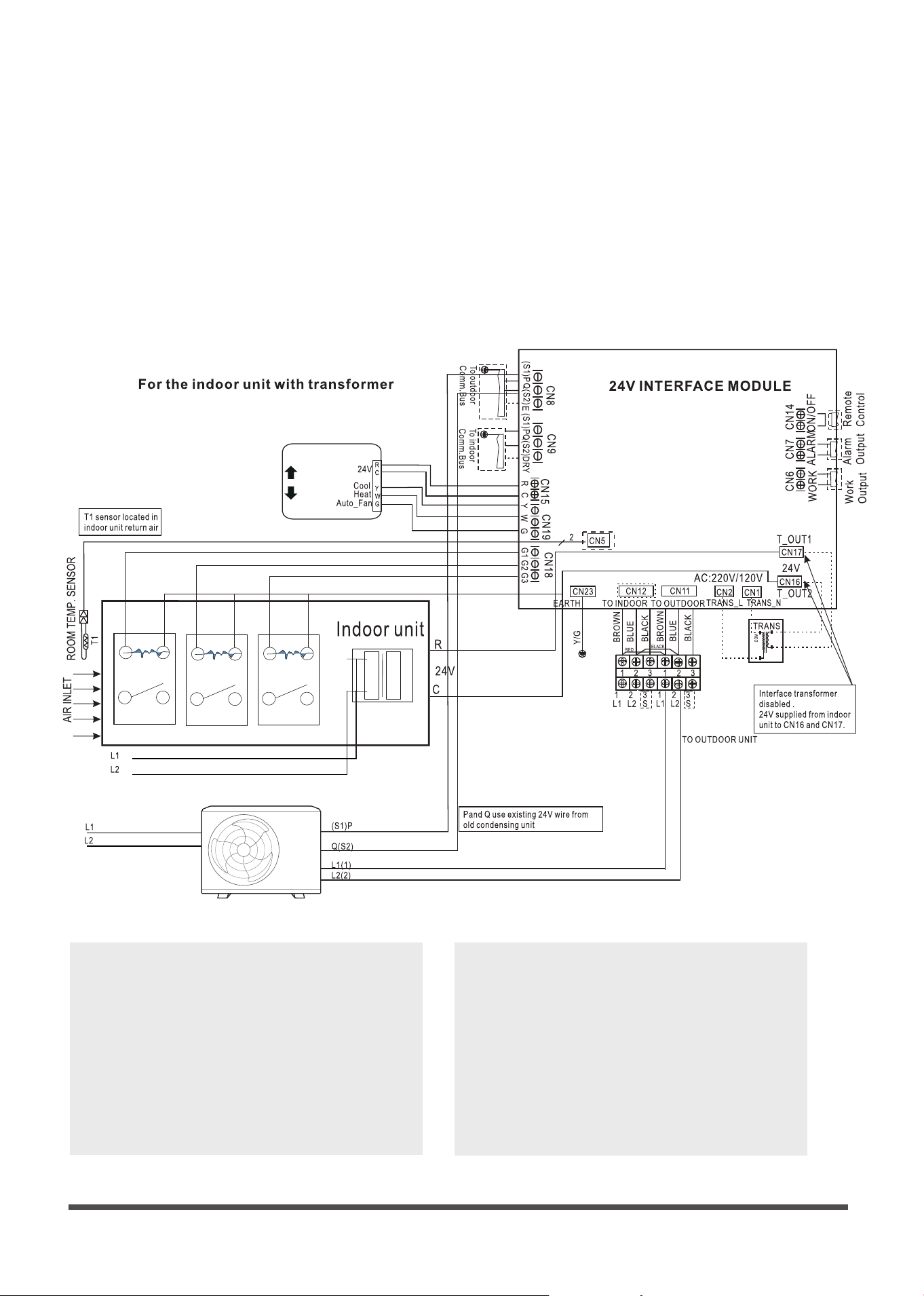
Application
* This system is designed for operation with standard 24 vac HVAC thermostats.
* Wi standard conguration HVAC thermostats may be used such as NEST, Ecobee, Honeywell, etc.
Thermostat
70
Fan Relay Fan Relay Fan Relay
NOTE:
T1(Room temperature) sensor should be
located in the air inlet side.
•
•
Must remove the TXV or other metering
device from the indoor unit.
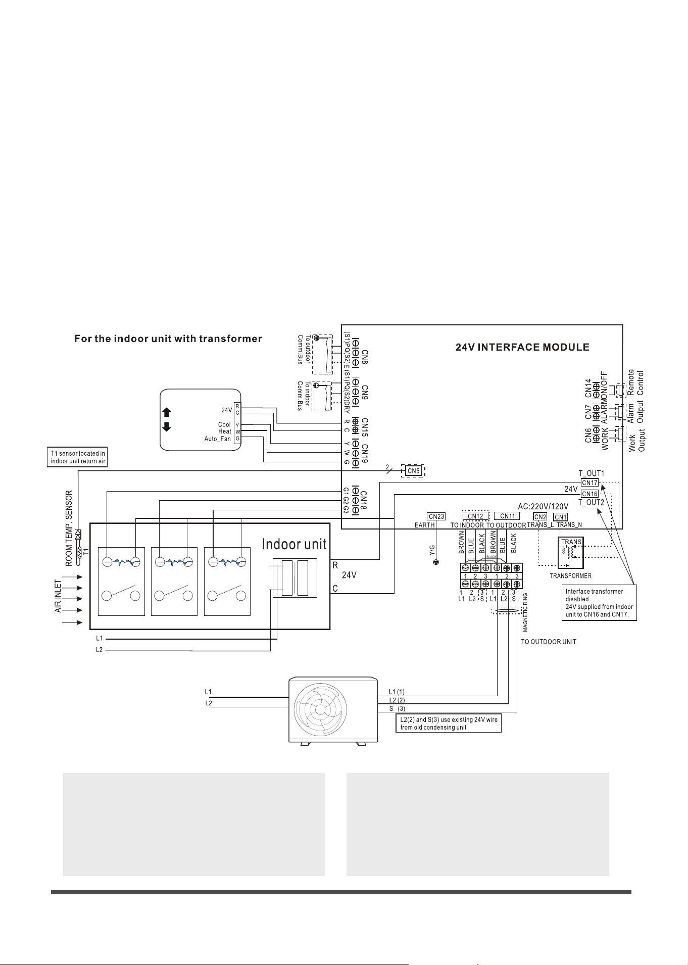
Page 4
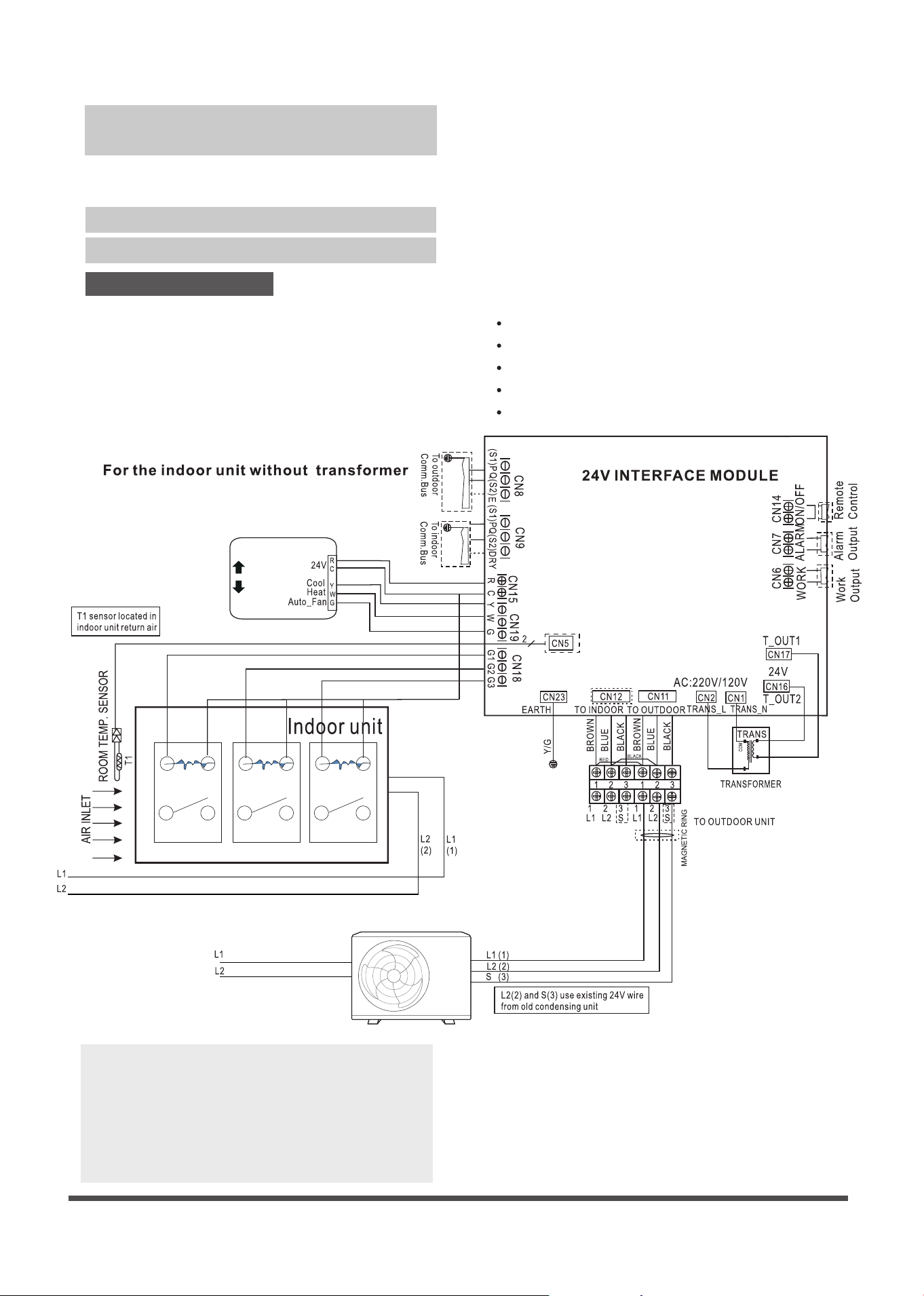
NOTE:
T1(Room temperature) sensor should be
located in the air inlet side.
•
•
Must remove the TXV or other metering
device from the indoor unit.
Fan Relay Fan Relay Fan Relay
Thermostat
70
Transformer
L1
L2
•
If the indoor unit already with a 24V
transformer , removing away the
transformer from the interface or
disconnect the transformer of the
interface.
Page 5
Must remove the TXV or other throttl-
ing device from the indoor.
•
NOTE:
T1(Room temperature) sensor should be
located in the air inlet side.
•
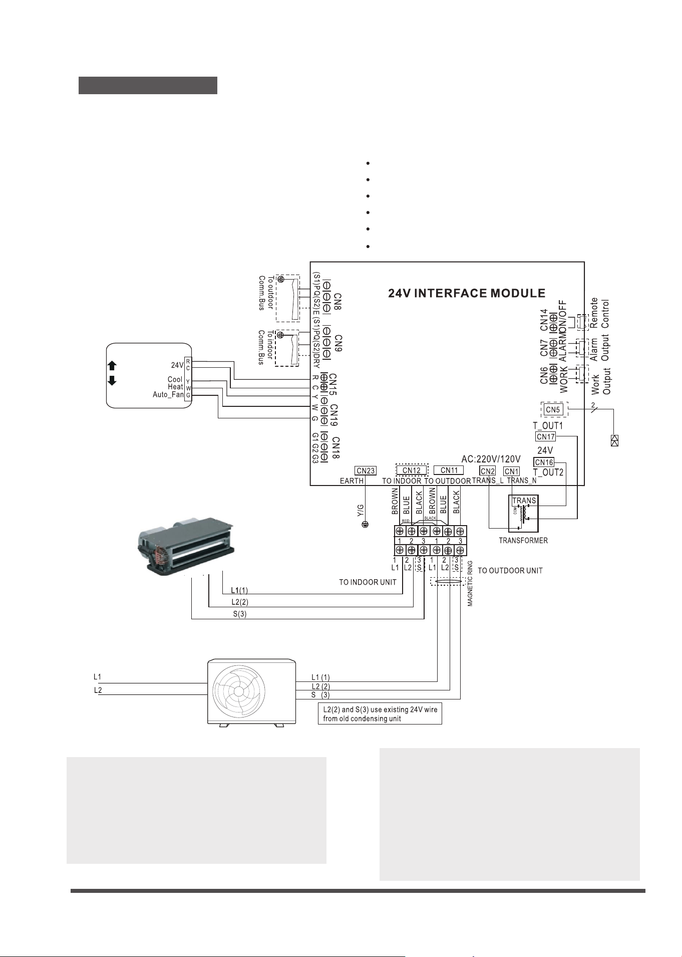
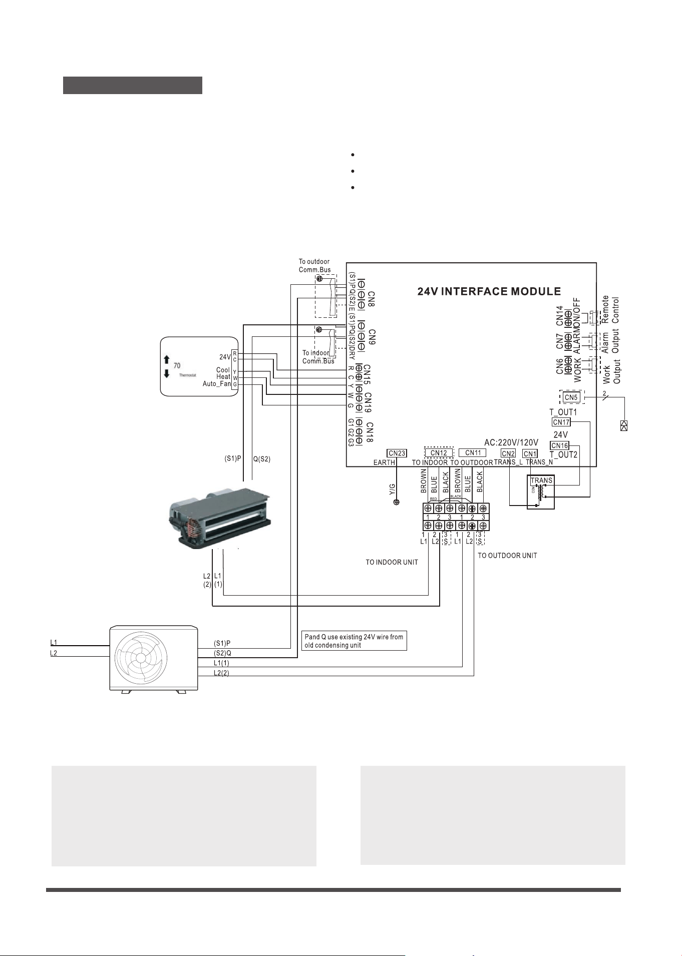
Scenario No. 2:
Match with following outdoor units :
Cassette (Sizes 36K~48K)
Ducted (Sizes 36K~60K)
Floor ceiling (Sizes 36K-60K)
485 (P Q)or( S1 S2) communication
inverter outdoor unit match with
conventional other brand 24V indoor unit;
Thermostat
70
Fan Relay
Fan Relay
Fan Relay
Page 6
Must remove the TXV or other throttl-
ing device from the indoor.
•
NOTE:
T1(Room temperature) sensor should be
located in the air inlet side.
•
Thermostat
70
Fan Relay
Fan Relay
Fan Relay
Transformer
L1
L2
If the indoor unit already has a 24V
transformer, removing the transformer
from the interface or disconnect the
transformer of the interface.
•
Thermostat
70
Page 7
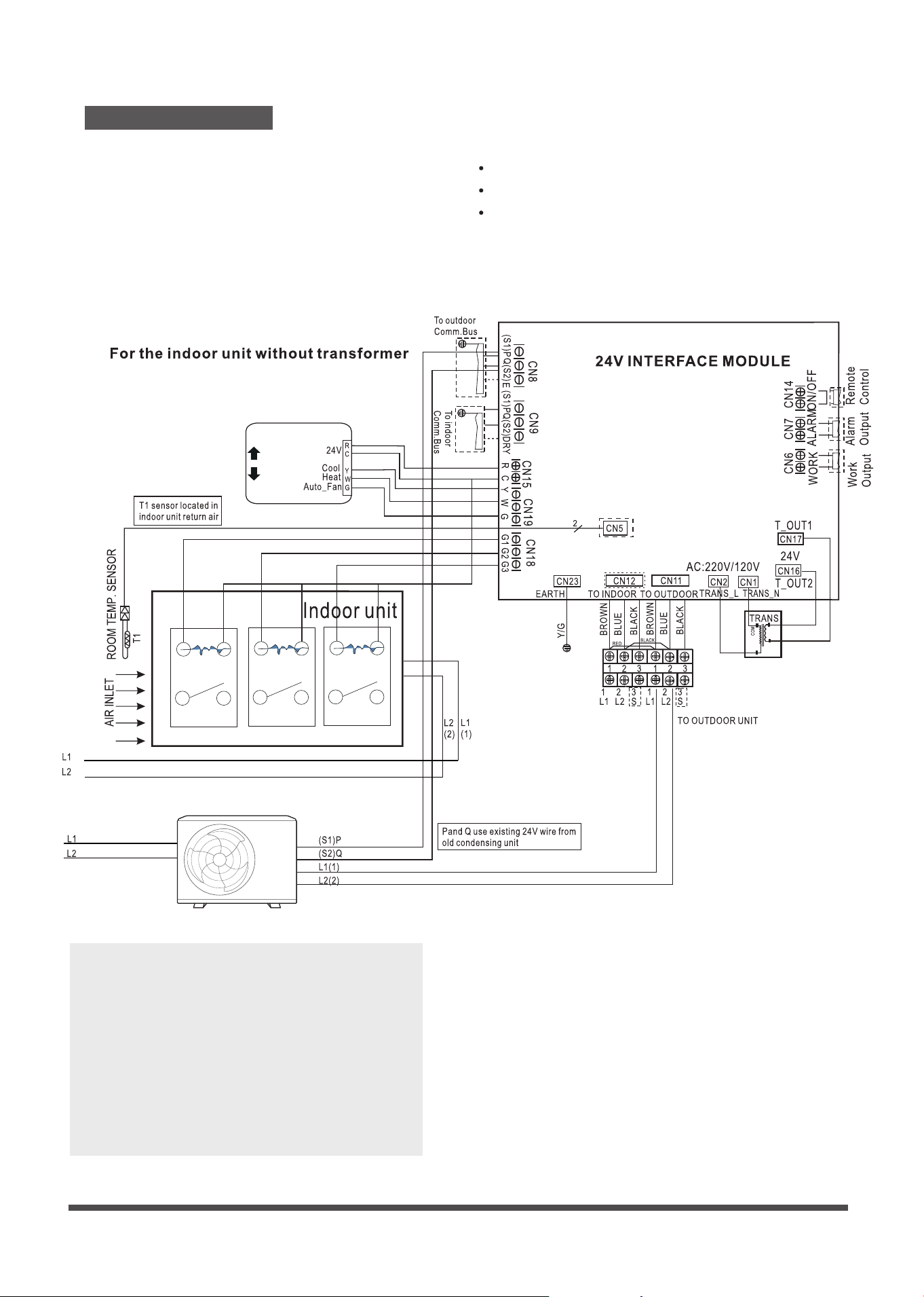
NOTE:
Please connect thermostat G to 24V
interface G as default.
•
Make sure the power supply is correct.
•
For Wall Mounted unit ,the up-down
swing louver and the display on/o
funcation is available by the wireless
remote controller.
•
Remove 24V control box T1 sensor when
match with indoor unit,which has T1
sensor.
•
Scenario No. 3:
Wall Mounted (Sizes 9K~36K)
Cassette (Sizes 9K~24K)
Console (Sizes 9K~12K)
Floor ceiling (Sizes 18K-24K)
Multi system (2 zone, 3 zone, 4 zone, 5 zone)
Ducted (Sizes 9K~24K)
Current loop (L1 L2 S or 1 2 3) inverter
outdoor unit match with current loop
inverter indoor unit;
Match the following indoor units with the
corresponding compatible SINGLE ZONE
and multi zone outdoor units:
Page 8
NOTE:
Make sure the power supply is correct.
Remove 24V control box T1 sensor when
match with indoor unit,which has T1
sensor.
•
•
•
Please connect thermostat G to 24V
interface G as default.
Scenario No. 4:
Cassette (Sizes 36K~48K)
Ducted (Sizes 36K~60K)
Floor ceiling (Sizes 36K-60K)
485 (P Q)or( S1 S2)inverter outdoor unit
match with 485 inverter indoor unit ;
Match the following indoor units
with the corresponding compatible
SINGLE ZONE outdoor units:
Page 9
OFF
ON or OFF
ON
√
X
*
Fan speed setting
Unit ON/OFF G Setting fan speed
√
√
√
X
X
X
√
Fan OFF
Auto fan speed
Auto fan speed
Mode setting
Y W G Aux/Dry Setting mode
√
√
√
√
X
X
X
X
X
X
X
X
X
X
X
*
√
√
**
*
√
*
*
*
*
Cooling
Heating
(without aux-heater)
Heating
(with aux-heater)
Fan only
OFF
OFF
X
X
Emergency heating
Dry
(Dry)
(AUX)
X
X
√
Control Logic
Connector
Y Cooling
W Heating
G Fan- Auto speed
AUX/DRY Aux-Heat/Dry
Connector Purpose
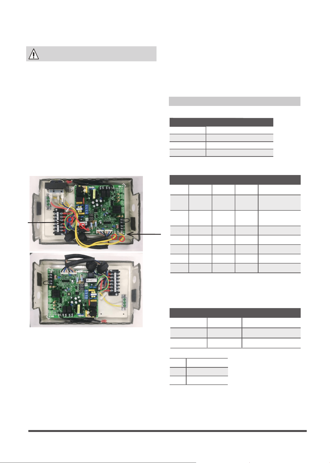
Key Considerations
•
Power switch on new board is changed.
Indoor unit power switch setting, ENC-1 must
be changed to the proper motor wattage:
Eg. 36K = 8 48K = 9
•
•
The following steps should be taken when
using this device with a Hi wall
(9K-36K Btu/hr) Cassette, Console, Duct,
Floor Ceiling (9K - 24K Btu/hr).
•
•
When the indoor air handler or furnace has
its own 24 vac transformer, you must
disconnect all four wires of the kit transformer.
The following steps should be taken when
using this device with a conventional
central air conditioning unit:
* Indoor coil metering device must be removed.
* 24V transformer in the interface module must
be disconnected.
* Refrigerant charge amount may need to be
adjusted,depending on the pipe size and
length,see outdoor recharge instruction.
* The maximum air ow should not exceed
400 CFM/Ton.
•
Suction and liquid refrigerant lines must be
properly insulated to prevent condensation
and energy loss.
•
You must remove the expansion device from
an indoor evaporator coil as the refrigerant is
controlled by a metering device in the
outdoor unit.
Page 10
Note
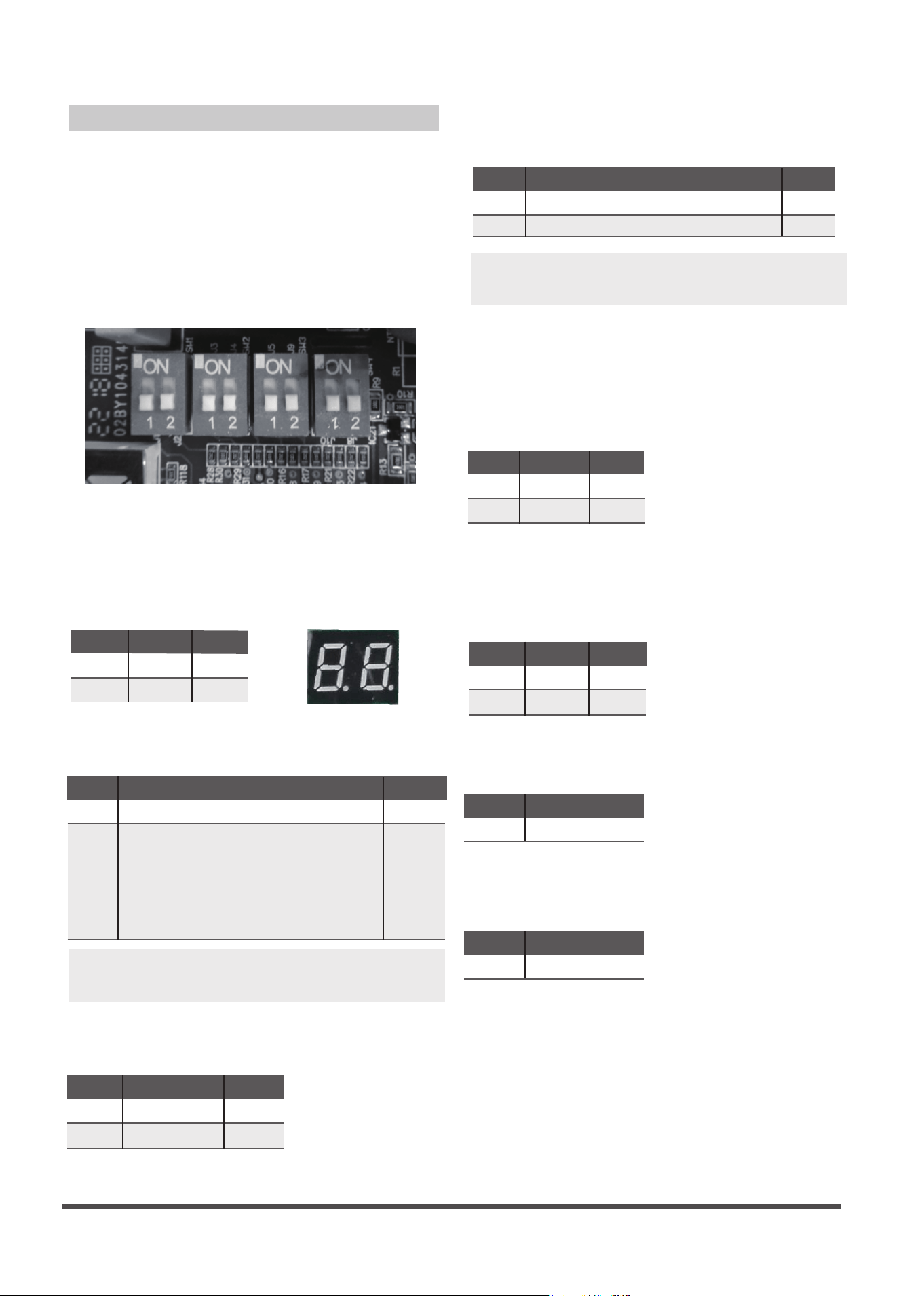
DIP Switch Denitions
DIP SWITCHES CONFIGURATION
The 24V INTERFACE KIT must be congured
to operate properly with the system
components with which it is installed. To
successfully congure the system move the
Dip Switches to match the components and
functions used.
DIP Switch Denitions
Dip Switch 1-2
NOTE: If this control box is matched with other
brand indoor unit, you must set OFF.
Used for selection of the indoor unit type.
Heat pump
Cooling only
SW2-1
ON
OFF
Result
Note
Default
Dip Switch 2-1
Used for selection of the system: Cooling Only
or Heat Pump.
SW1-2
Result
ON
OFF
Sets - Both Ductless Indoor and Outdoor Units
Outdoor only
----- Compatible with other x speed 24V control
indoor (Wall Hung/ Pancake etc.).
Note:
1) Need to remove the indoor unit throttle (piston/
TXV/ orice);
2) Indoor fan may not stop during the defrost.
Default
Note
Fan will stop if the indoor coil temperature is low
Fan do not stop
SW2-2
ON
OFF
Result
Note
Default
Dip Switch 2-2
Used for freeze protection of the indoor coil.
NOTE: Applicable only to Ductless Style Indoor
(scenario 3 and 4) Heat Pump units in Heating Mode.
Aux-heater
Dry
SW3-1
ON
OFF
Result
Note
Default
Dip Switch 3-1
Dry is used for thermostats with a Dry Function
output. An auxiliary heater is used on the Ducted
Style Indoor Units
(scenario 3 and 4)
to control a
secondary Heat Source.
Dip Switch 4-2
Dip Switch 4-1
30min
1h
SW3-2
ON
OFF
Result
Note
Default
Default
Dip Switch 3-2
Used to increase the compressor frequency
in case the set point has not been reached
after 1 hour or 30min of operation.
For factory test only.
For factory test only.
Display on
SW1-1
ON
OFF
Result
Note
Default
Display o
Dip Switch 1-1
Used to turn ON or OFF the diagnostic code
display LED on the control board of the 24V
Interface Kit.
SW4-1
OFF
Note
Default
SW4-2
OFF
Note
Page 11
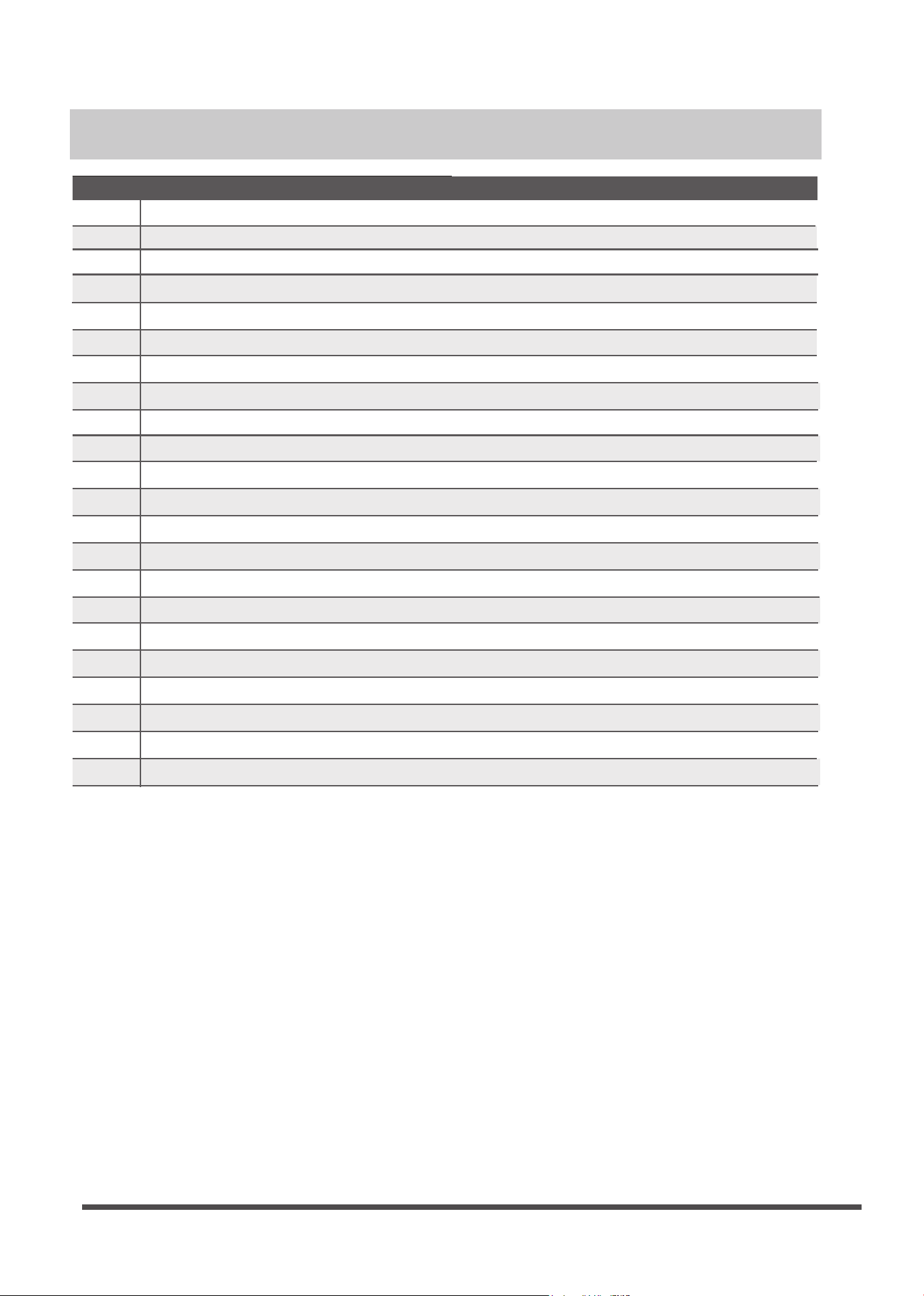
Malfunction & protection indication
Display
E0
E2
E3
E4
E5
EC
F0
F1
F2
F3
Error Codes
F4
F5
P0
F6
P1
P2
P3
P4
P6
00
IN
OU
Indoor EEPROM error
Cross-zero detection error
Indoor fan speed malfunction
Indoor room temperature sen sor error
Evaporator coil temperature sensor error
Refrigerant leak detection system malfunction
Current overload protection
Outdoor ambient temperature sensor (T4 ) malfunction
Condenser coil temperature sensor (T3) malfunction
Condenser coil temperature sensor (T5) malfunction
Outdoor unit EEPROM parameter error
Outdoor fan speed has been out of control
Inverter module (IPM) malfunction
T2b sensor error
Over-voltage or under-voltage protection
Compressor top high temperature protection (OLP)
Low ambient temperature cut o in heating
Compressor drive malfunction
Compressor low-pressure protection
Module boot mode and indoor running mode for power o
Module and indoor unit communication malfunction
Module and outdoor unit communication malfunction
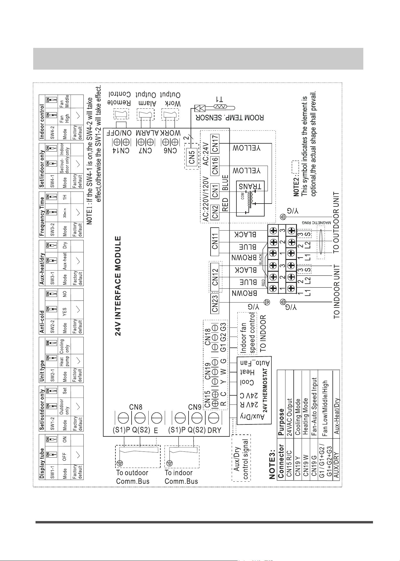
Wiring Diagram
Page 12


QSKZHI-002AEN
16111600000068
20221213
The design and specications are subject to change without prior notice for product
improvement.Consult with the sales agency or manufacturer for details.

此面无需印刷
技术 要求:
1. 双胶纸(说明书)80g非E项目大度
2.尺寸:210*297mm
3.颜色:黑白
4.注意:排版时注意页码数字都是靠外面的,以便翻阅
5.装订。
修订
1)改善用户体验,优化说明书安装配图。2022.12.13