TD 50
INSTALLATION INSTRUCTIONS
Important Safety Information
WARNING
Failure to follow these warnings, cautions, and notices could result in personal injury, damage to the vessel or
device, or poor product performance.
See the Important Safety and Product Information guide in the product box for product warnings and other
important information.
CAUTION
To avoid possible personal injury, always wear safety goggles, ear protection, and a dust mask when drilling,
cutting, or sanding.
To avoid possible personal injury or damage to the device and vessel, disconnect the vessel's power supply
before beginning to install the device.
To avoid possible personal injury or damage to the device or vessel, before applying power to the device, make
sure that it has been properly grounded, following the instructions in the guide.
NOTICE
For the best possible performance, the device must be installed according to these instructions.
When drilling or cutting, always check what is on the opposite side of the surface to avoid damaging the vessel.
Tools Needed
• Drill and drill bits
◦ Preparing the surface for cutting:
9mm (
3
/
8
in.) bit
◦ Installs using wood screws:
2.5mm (
3
/
32
in.) bit
◦ Installs using the nut plate:
3.5mm (
9
/
64
in.) bit
4mm (
5
/
32
in.) bit
• #2 Phillips screwdriver
• Jigsaw or rotary tool
• File and sandpaper
• Marine sealant (recommended)
GUID-0E4EF44F-C334-4343-867C-0A6410D364DB v3
January 2025

Mounting Considerations
NOTICE
This device should be mounted in a location that is not exposed to extreme temperatures or conditions. The
temperature range for this device is listed in the product specifications. Extended exposure to temperatures
exceeding the specified temperature range, in storage or operating conditions, may cause device failure.
Extreme-temperature-induced damage and related consequences are not covered by the warranty.
The mounting surface must be flat to avoid damaging the device when it is mounted.
When selecting a mounting location, observe these considerations.
• The mounting location should be at or below eye level to provide optimal viewing as you operate your vessel.
• The mounting surface must be strong enough to support the weight of the device and protect it from
excessive vibration or shock.
• To avoid interference with a magnetic compass, the device should not be installed closer to a compass than
the compass-safe distance value listed in the product specifications.
• The area behind the mounting surface must allow room for the routing and connection of the cables.
The included template and hardware can be used to flush mount the device in your dashboard. There are two
options for hardware based on the mounting surface material.
• You can drill pilot holes and use the included wood screws.
• You can drill holes and use the included nut plates and machine screws. The nut plates can add stability to a
thinner surface.
Mounting the Device
NOTICE
Be careful when cutting the hole to flush mount the device. There is only a small amount of clearance between
the case and the mounting holes, and cutting the hole too large could compromise the stability of the device
after it is mounted.
To avoid potential damage to the device, use only the included screws to mount it. Using screws other than the
ones included will void your warranty.
The included template and hardware can be used to flush mount the device in your dashboard. There are two
options for hardware based on the mounting surface material.
• You can drill pilot holes and use the included wood screws.
• You can drill holes and use the included nut plates and machine screws. The nut plates can add stability to a
thinner surface.
1 Trim the template and make sure it fits in the location where you want to mount the device.
2 Secure the template to the selected location.
3 Using a 9mm (
3
/
8
in.) drill bit, drill one or more of the holes inside the corners of the solid line on the
template to prepare the mounting surface for cutting.
4 Using a jigsaw or rotary tool, cut the mounting surface along the inside of the solid line indicated on the
template.
5 Place the device in the cutout to test the fit.
6 If necessary, use a file and sandpaper to refine the size of the cutout.
7 After the device fits correctly in the cutout, ensure the mounting holes on the device line up with the holes on
the template.
8 If the mounting holes on the device do not line up, mark the new hole locations.
9 Based on your mounting method, drill the outer holes on the template:
• Drill 2.5mm (
3
/
32
in.) pilot holes for the included wood screws, and skip to step 18.
• Drill 3.5mm (
9
/
64
in.) holes for the included nut plate and machine screws.
2
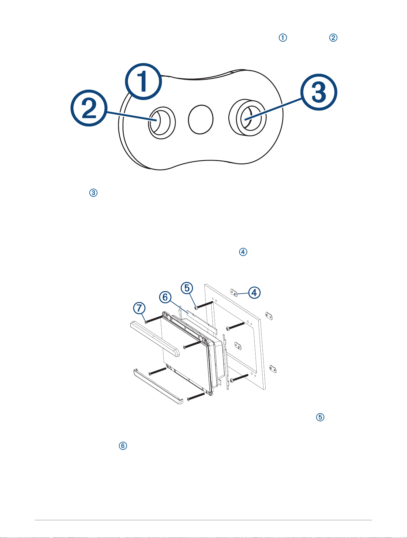
10 If using the nut plates, starting in one corner of the template, place a nut plate over the hole drilled in
the previous step.
The other hole on the nut plate should line up with the inner 4mm (
5
/
32
in.) hole on the template.
11 If the 4mm (
5
/
32
in.) hole on the nut plate does not line up with the inner hole on the template, mark the new
location.
12 Repeat steps 10 and 11 for each nut plate.
13 Using a 4mm (
5
/
32
in.) drill bit, drill the inner holes.
14 Remove the template from the mounting surface.
15 Starting in one corner of the mounting location, place a nut plate on the back of the mounting surface,
lining up the inner and outer holes.
The raised portion of the nut plate should fit into the inner hole.
16 Secure the nut plate to the mounting surface by fastening an included M3 pan-head screw through the
inner 4mm (
5
/
32
in.) hole.
17 Repeat steps 15 and 16 for each of the nut plates along the top and bottom of the device.
18 Install the gasket pieces on the back of the device.
The pieces of the rubber gasket have adhesive on the back. Make sure you remove the protective liner before
installing them on the device.
19 If you will not have access to the back of the device after you mount it, connect all necessary cables to the
device before placing it into the cutout.
20 Place the device into the cutout.
3
21 Secure the device to the mounting surface using the included M3 flat-head screws or wood screws ,
depending on the mounting method.
22 Snap the trim caps into place over the screws.
Connection Considerations
This device connects to power and to some data sources through a NMEA 2000
®
network.
You must connect this device to Garmin
®
Marine Network devices using a nine-pin Garmin Marine Network
cable (sold separately). You must use an adapter to connect to Garmin network devices that have a larger
connector (sold separately).
NOTE: This device must be connected to the Garmin Marine Network with one or more compatible Garmin
chartplotters also connected. This device will not function as a stand-alone device.
NMEA 2000 Connection Considerations
NOTICE
If you are connecting to an existing NMEA 2000 network, identify the NMEA 2000 power cable. Only one NMEA
2000 power cable is required for the NMEA 2000 network to operate properly.
A NMEA 2000 Power Isolator (010-11580-00) should be used in installations where the existing NMEA 2000
network manufacturer is unknown.
If you are installing a NMEA 2000 power cable, you must connect it to the boat ignition switch or through
another in-line switch. NMEA 2000 devices will drain your battery if the NMEA 2000 power cable is connected to
the battery directly.
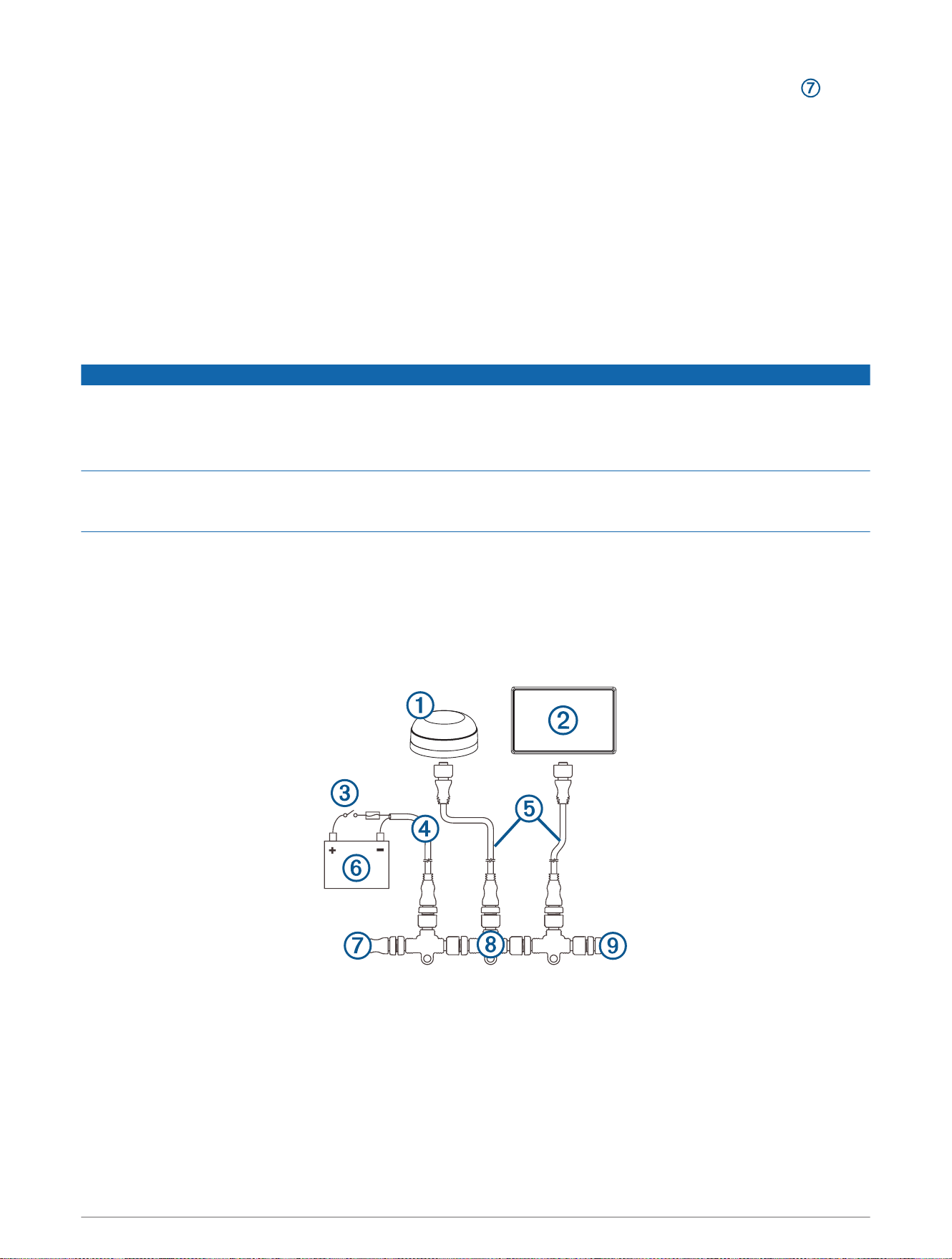
The marine instrument connects to a NMEA 2000 network on your boat. The NMEA 2000 network provides
power to the marine instrument and data from NMEA 2000 devices such as a wind sensor. The included NMEA
2000 cables and connectors allow you to either connect the device to your existing NMEA 2000 network or
create a basic NMEA 2000 network if needed.
If you are unfamiliar with NMEA 2000, you should read the “NMEA 2000 Network Fundamentals” chapter of the
Technical Reference for NMEA 2000 Products. To download the reference, go to dealers.garmin.com.
4
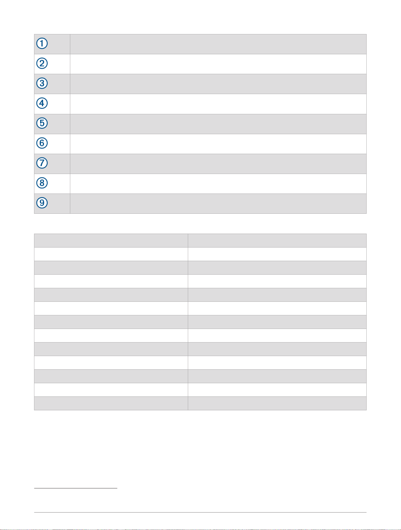
NMEA 2000 antenna
Marine instrument
Ignition or in-line switch
NMEA 2000 power cable
NMEA 2000 drop cable
12Vdc power source
NMEA 2000 terminator or backbone cable
NMEA 2000 T-connector
NMEA 2000 terminator or backbone cable
Specifications
Dimensions without sun cover (H × W × D) 105 x 140 x 51mm (4.13 x 5.51 x 2.01in.)
Dimensions with sun cover (H × W × D) 113 x 144 x 56mm (4.45 x 5.67x 2.20in.)
Weight without sun cover 328g (11.57oz.)
Weight with sun cover 375g (13.23oz.)
Temperature range From 5° to 131°F (from -15° to 55°C)
Compass-safe distance 20cm (7.87in.)
Case material Fully-gasketed polycarbonate
Lens material Glass with an anti-glare and anti-fingerprint finish
Water rating IEC 60529 IPX7
1
Brightness 1200 cd/m
2
(NIT)
Power usage 5.85W max
NMEA 2000 input voltage 9 to 16Vdc
NMEA 2000 LEN @ 9Vdc 13 (650mA)
1
The device withstands incidental exposure to water of up to 1m for up to 30min. For more information, go to www.garmin.com/waterrating.
5

NMEA 2000 PGN Information
Transmit and Receive
PGN Description
059392 ISO acknowledgment
059904 ISO request
060928 ISO address claim
61184 Product information
126208 NMEA
®
: Command, request, and acknowledge group function
126996 Product information
Transmit
PGN Description
126464 Transmit PGN list group function
Receive
PGN Description
126992 System time
127245 Rudder
127250 Vessel heading
127488 Engine parameters: Rapid update
127489 Engine parameters: Dynamic
127508 Battery status
128259 Speed: Water referenced
128267 Water depth
129025 Position: Rapid update
129026 COG and SOG: Rapid update
129029 GNSS position data
129283 Cross track error
129284 Navigation data
129285 Navigation route and waypoint info
129539 GNSS dilution of precision (DOP)
130306 Wind data
130310 Environmental parameters
130311 Environmental parameters
130312 Temperature
6

PGN Description
130313 Humidity
130314 Actual pressure
© 2020 Garmin Ltd. or its subsidiaries
Garmin
®
and the Garmin logo are trademarks of Garmin Ltd. or its subsidiaries, registered in the USA and other countries. These trademarks may not be used without the
express permission of Garmin.
NMEA
®
, NMEA 2000
®
, and the NMEA 2000 logo are registered trademarks of the National Marine Electronics Association.
7

© 2020 Garmin Ltd. or its subsidiaries
support.garmin.com