
I worked really hard
on this manual - so
please read it...
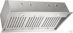
XOI INSERT | POWER PACK
MODELS XOI3015SC, XOI3315SC


- 3 -
When buying any XO appliance
you can be confident you have chosen a
high quality, innovative and stylish product
from a company that cares about you!
If you require service or have questions,
there are 2 ways to contact our ventilation experts;
Online @ https://xoappliance.com/priority-service-for-your-xo-product/
Or by phone 973-403-8900
CONGRATULATIONS
on purchasing your XO.
Before you proceed, take just a
moment to register your XO at:
www.xoappliance.com/register-your-product/
REGISTRATION HELPS YOU BY -
Ensuring warranty coverage should you need service
Providing ownership verification for insurance purposes
Let’s XO notify you in the event of product changes or recalls.

- 4 -
It’s for your
own good...
Honest.
please read and follow
all safety instructions
where things are
GETTING READY
Safety and Precautions
Planning Ductwork
Install Examples
Dimensions
THE INSTALL
Mounting Height
Cut Out Dimensions
Installing
Electrical Connections
MAINTENANCE
Filters
Cleaning
Recirculation
Light Replacement
OPERATING
The Push Button Controls
CCC Make Up Air Conversion
PARTS & WARRANTY
20 - 21
22 - 23
5 - 11
12 - 17
18 - 19
- 5 -
safety first
IMPORTANT SAFETY INSTRUCTIONS
FOR RESIDENTIAL USE ONLY
READ AND SAVE THESE INSTRUCTIONS
PLEASE READ ENTIRE INSTRUCTIONS BEFORE PROCEEDING.
IMPORTANT: Save these Instructions for the Local Electrical Inspectors use.
INSTALLER: Please leave these Instructions with this unit for the owner.
OWNER: Please retain these instructions for future reference.
Take care when using cleaning agents or detergents.
Suitable for use in household cooking area.
WARNING - To reduce the risk of fire or electric shock, do not use this fan with any
Solid-State Speed Control Device.
CAUTION - To reduce risk of fire and to properly exhaust air, be sure to duct air out-
side – Do not vent exhaust air into spaces within walls or ceilings or into attics, crawl
spaces, or garages.
CAUTION - For Residential Kitchen ventilating use only. Do not use to exhaust haz-
ardous or explosive materials and vapors.
CAUTION - To avoid motor bearing damage and noisy and/or unbalanced impellers,
keep drywall spray, construction dust, etc. off power unit.
CAUTION - Please read specification label on product for further information and
requirements.
WARNING – TO REDUCE THE RISK OF FIRE, ELECTRIC SHOCK, OR INJURY TO PERSONS,
OBSERVE THE FOLLOWING:
A. Use this unit only in the manner intended by the manufacturer. If you have questions,
contact the manufacturer.
B. Before servicing or cleaning unit, switch power off at service panel and lock the ser-
vice disconnecting means to prevent power from being switched on accidentally.
When the service disconnecting means cannot be locked, securely fasten a promi-
nent warning device, such as a tag, to the service panel.
WARNING - TO REDUCE THE RISK OF A RANGE TOP GREASE FIRE:
A. Never leave surface units unattended at high settings. Boilovers cause smoking and
- 6 -
greasy spillovers that may ignite. Heat oils slowly on low or medium settings.
B. Always turn hood ON when cooking at high heat.
C. Clean ventilating fans frequently. Grease should not be allowed to accumulate on
fan or filter.
D. Use proper pan size. Always use cookware appropriate for the size of the surface
element.
E. Keep fan, filters and grease laden surface clean.
F. Use high range setting on range only when necessary.Heat oil slowly on low to me-
dium setting.
G. Don’ t leave range unattended when cooking.
H. Always use cookware and utensils appropriate for the type and amount off food be-
ing prepared.
WARNING – TO REDUCE THE RISK OF INJURY TO PERSONS IN THE EVENT OF A RANGE
TOP GREASE FIRE, OBSERVE THE FOLLOWING:
A. SMOTHER FLAMES with a close-fitting lid, cookie sheet, or metal tray, then turn off
the burner. BE CAREFUL TO PREVENT BURNS. If the flames do not go out immediately,
EVACUATE AND CALL THE FIRE DEPARTMENT.
B. NEVER PICK UP A FLAMING PAN – You may be burned.
C. DO NOT USE WATER, including wet dishcloths or towels – a violent steam explosion
will result.
D. Use an extinguisher ONLY if:
1. You know you have a Class ABC extinguisher, and you already know how to operate it.
2. The fire is small and contained in the area where it started.
3. The fire department is being called.
4. You can fight the fire with your back to an exit.
a
Based on “kitchen firesafety tips” published by NFPA.
Proper maintenance of the Range Hood will assure proper performance of the
unit.
INSTALLATION INSTRUCTIONS
WARNING – TO REDUCE THE RISK OF FIRE, ELECTRIC SHOCK, OR INJURY TO PERSONS,
OBSERVE THE FOLLOWING:
A. Installation work and electrical wiring must be done by qualified person(s) in accord-
ance with all applicable codes and standards, including fire-rated construction.
B. Sufficient air is needed for proper combustion and exhausting of gases through the
flue (chimney) of fuel burning equipment to prevent back drafting. Follow the heat-
ing equipment manufacturer’s guideline and safety standards such as those pub-
lished by the National Fire Protection Association (NFPA), and the American Society

- 7 -
for Heating, Refrigeration and Air Conditioning Engineers (ASHRAE), and the local
code authorities.
C. When cutting or drilling into wall or ceiling, do not damage electrical wiring and
other hidden utilities.
D. Ducted fans must always be vented to the outdoors.
E. This unit must be grounded.
WARNING - TO REDUCE THE RISK OF FIRE, USE ONLY METAL DUCTWORK.
WARNING - UNDER CERTAIN CIRCUMSTANCES DOMESTIC APPLIANCES MAY BE
DANGEROUS.
A. Do not check filters with hood working.
B. Do not touch the lamps after a prolonged use of the appliance.
C. No food must be cooked flambè underneath the hood.
D. The use of an unprotected flame is dangerous for the filters and could cause fires.
E. Watch constantly the fried food in order to avoid the cooking oil flares up.
F. Before performing any mainteinance operation, disconnect the hood from the
electrical service.
The manufacturers will not accept any responsibility for possible damages, because
of failure to observe the above instructions.

- 8 -
THIS HOOD IS DESIGNED TO USE A 6” ROUND DUCT -
IT MAY BE TRANSITIONED TO A 3-1/4” X 10” RECTANGULAR DUCT
NEVER REDUCE DUCT SIZE. UNDERSIZED DUCTING SEVERELY RESTRICTS AIR
FLOW AND HARMS PERFORMANCE.
(Example: the area of a 6” Duct is more than TWICE that of a 4” Duct)
KEEP DUCT RUNS AS SHORT AND STRAIGHT AS POSSIBLE.
AVOID USING FLEXIBLE METAL DUCTING IF RUN IS LONGER THAN 6’.
NEVER USE PLASTIC DUCTING.
USE SMOOTH BORE METAL DUCTING.
MINIMIZE THE NUMBER OF FITTINGS (see chart).
WHEN YOU MUST USE FITTINGS, TRY TO SEPARATE THEM WITH SECTIONS OF
3’ OR MORE OF STRAIGHT DUCT.
ALWAYS FOLLOW THE MANUFACTURER’S GUIDELINES FOR THE COOKING
EQUIPMENT YOU ARE VENTING.
IF MAKE UP AIR CONTROL DAMPERS ARE REQUIRED, POSITION THE SENSOR
IN A STRAIGHT RUN OF DUCT IDEALLY WITH 3’ OF STRAIGHT DUCT BETWEEN
EACH SIDE OF THE SENSOR AND A DUCT FITTING. REMEMBER TO INCLUDE
POWER AND CONTROL WIRING FOR THIS IN YOUR PLANS.
ADHERE TO ALL LOCAL BUILDING CODES AND ORDINANCES.
USE THE WORKSHEET THAT FOLLOWS TO HELP CALCULATE THE
TOTAL EQUIVILENT FEET OF YOUR DUCT RUN.
TOTAL EQUIVILENT FEET SHOULD BE LESS THAN 100’.
a few simple rules to plan your
ductwork
1
1
12
7
14
8
33
2
4
24
24
33

- 9 -
1
1
12
7
14
8
33
2
4
24
24
33
CAUSING AIR TO CHANGE DIRECTION CAUSES TURBULENCE AND RESTRICTS FLOW IN
A SYSTEM.
IF USING FLEXIBLE METAL DUCT - INCREASE ALL MULTIPLIERS BY 50% (12 BECOMES
18 - ETC.)
THIS EASY TO USE WORKSHEET IS FOR 600 CFM OR LESS.
UNDER “QTY USED” ENTER HOW OF EACH SECTION YOU WILL BE USING.
IN THE FIRST TWO ROWS - ENTER HOW MANY FEET OF EACH TYPE OF STRAIGHT DUCT
YOU WILL BE USING (I.E. FOR 20 FT ENTER 20, FOR 30FT ENTER 30).
ENTER THE NUMBER OF EACH TYPE OF TURN YOU ARE USING AND THE TYPE OF END CAP.
MULTIPLY ACROSS EACH ROW THE “MULTIPLIER” x “QTY USED” TO GET THE EQUIVALENT
FEET FOR THOSE COMPONENTS.
ADD UP ALL THE VALUES IN THE “EQUIVALENT FEET” COLUMN.
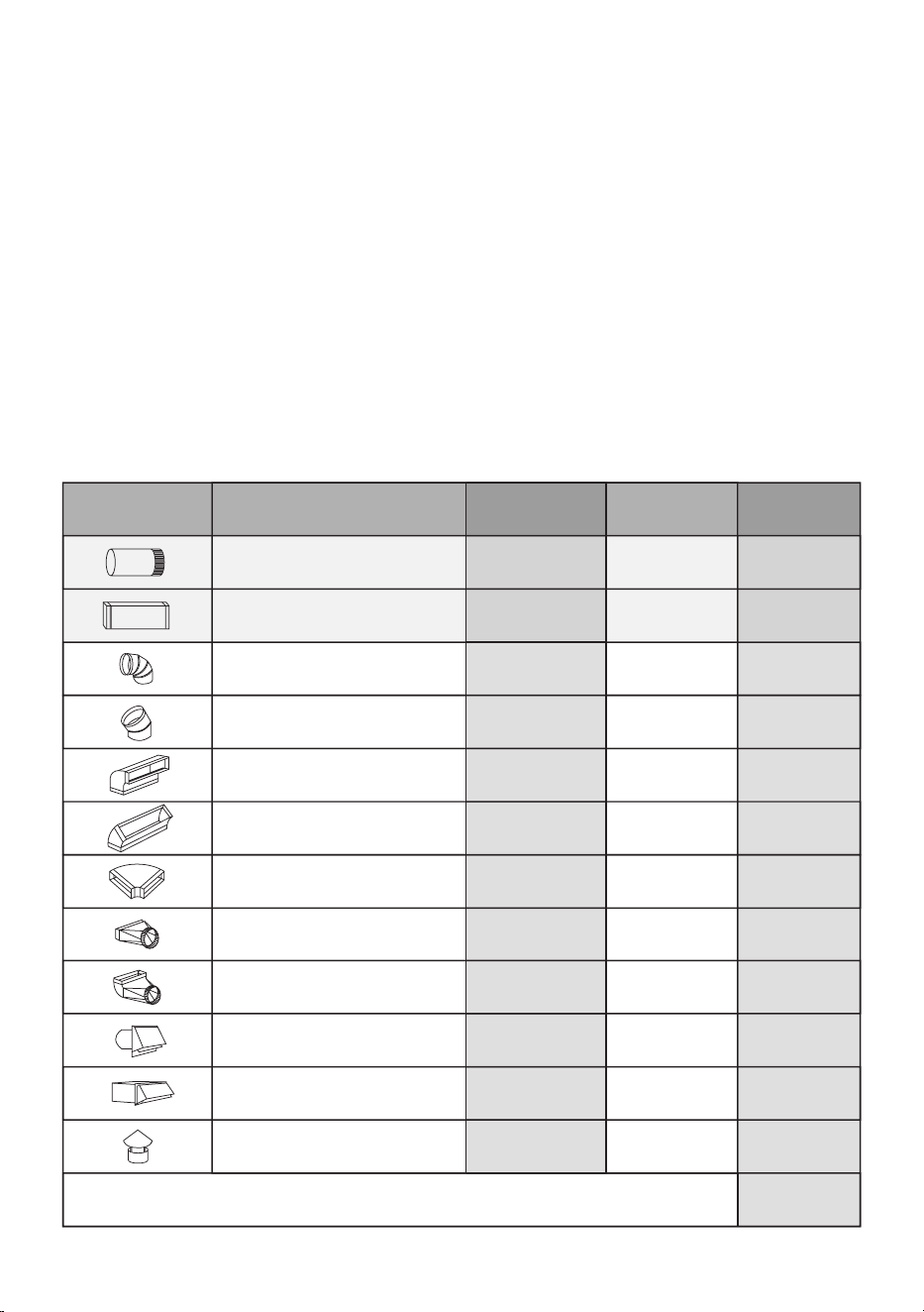
DUCT PIECE DESCRIPTION MULTIPLIER QTY USED
EQUIVALENT
FEET
1’ of 6” Round Duct
1’ of 3 1/4“ x 10” Rect. Duct
6” 90 Degree Elbow
6” 45 Degree Elbow
3 1/4” x 10” 90 Degree
3 1/4” x 10” 45 Degree
3 1/4” x 10” Side 90 Degree
3 1/4” x 10” x 6” Round
3 1/4” x 10” x 6” 90 Degree
6” Round Wall Cap w Damper
3 1/4” x 10” Wall Cap w Damper
6” Round Roof Cap
TOTAL EQUIVALENT FEET SHOULD BE LESS THAN 100
estimating total equivalent feet in
a duct
- 10 -
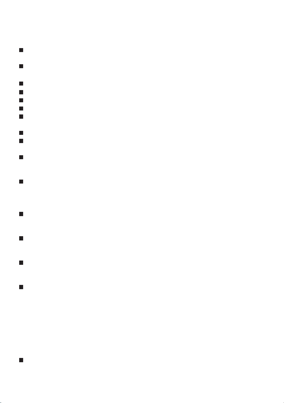
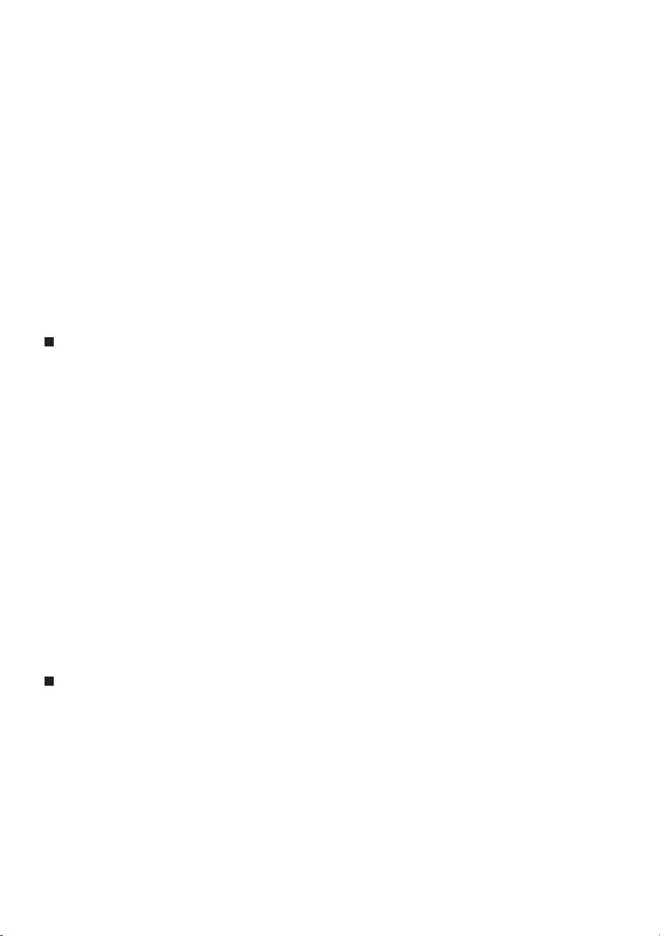
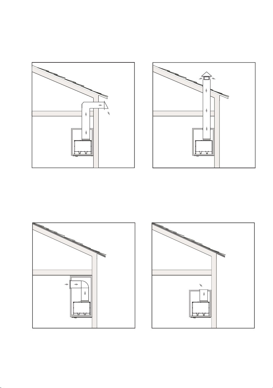
VENTEDRECIRCULATION
WALL EXHAUST ROOF EXHAUST
SOFFIT EXHAUST
RECIRCULATION EXHAUST MUST BE RETURNED TO THE
SPACE
typical installation examples
2-1/16"2-1/16"
1-1/16"
4-1/4"4-1/4"
1-3/16"
12-5/8"
15"
Ø 6"
11-1/2"
15/16"
“A”
1-1/4"
“C”
“B”
Ø6"
CABINET TOP EXHAUST

- 11 -
2-1/16"2-1/16"
1-1/16"
4-1/4"4-1/4"
1-3/16"
12-5/8"
15"
Ø 6"
11-1/2"
15/16"
“A”
1-1/4"
“C”
“B”
Ø6"
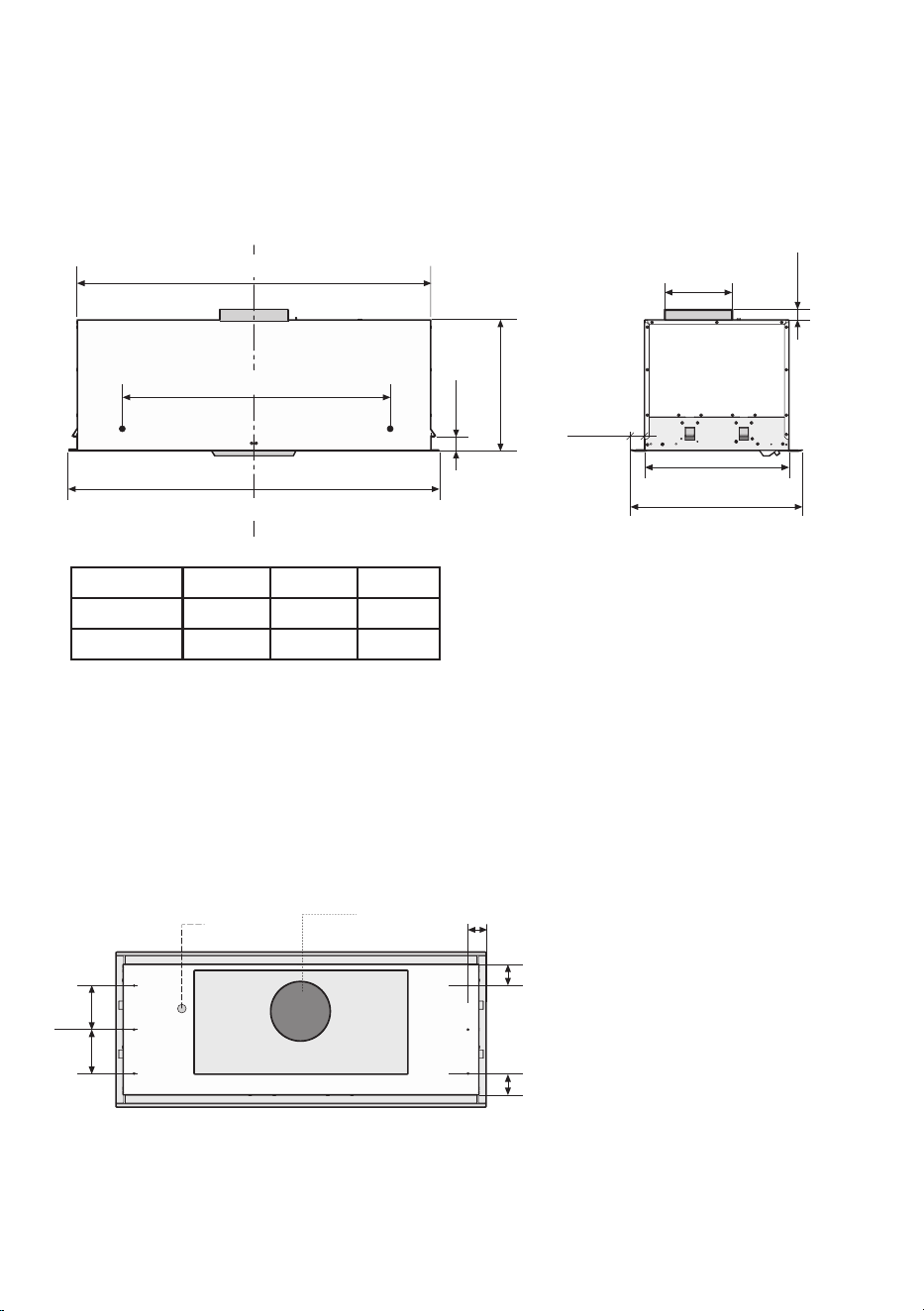
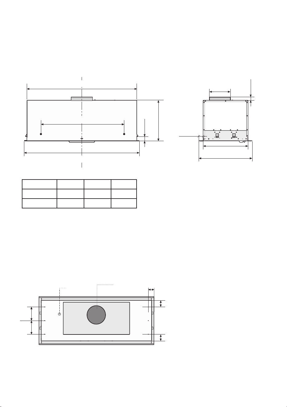
› Front of hood › Side of hood
› Top of hood
dimensions
ELECTRICAL
CONNECTION
KNOCK OUT
MODEL A B C
XOI3015SC
26-3/8”
18-1/2” 27-3/4”
XOI3315SC
32-3/8”
24-1/2” 33-3/4”

- 12 -
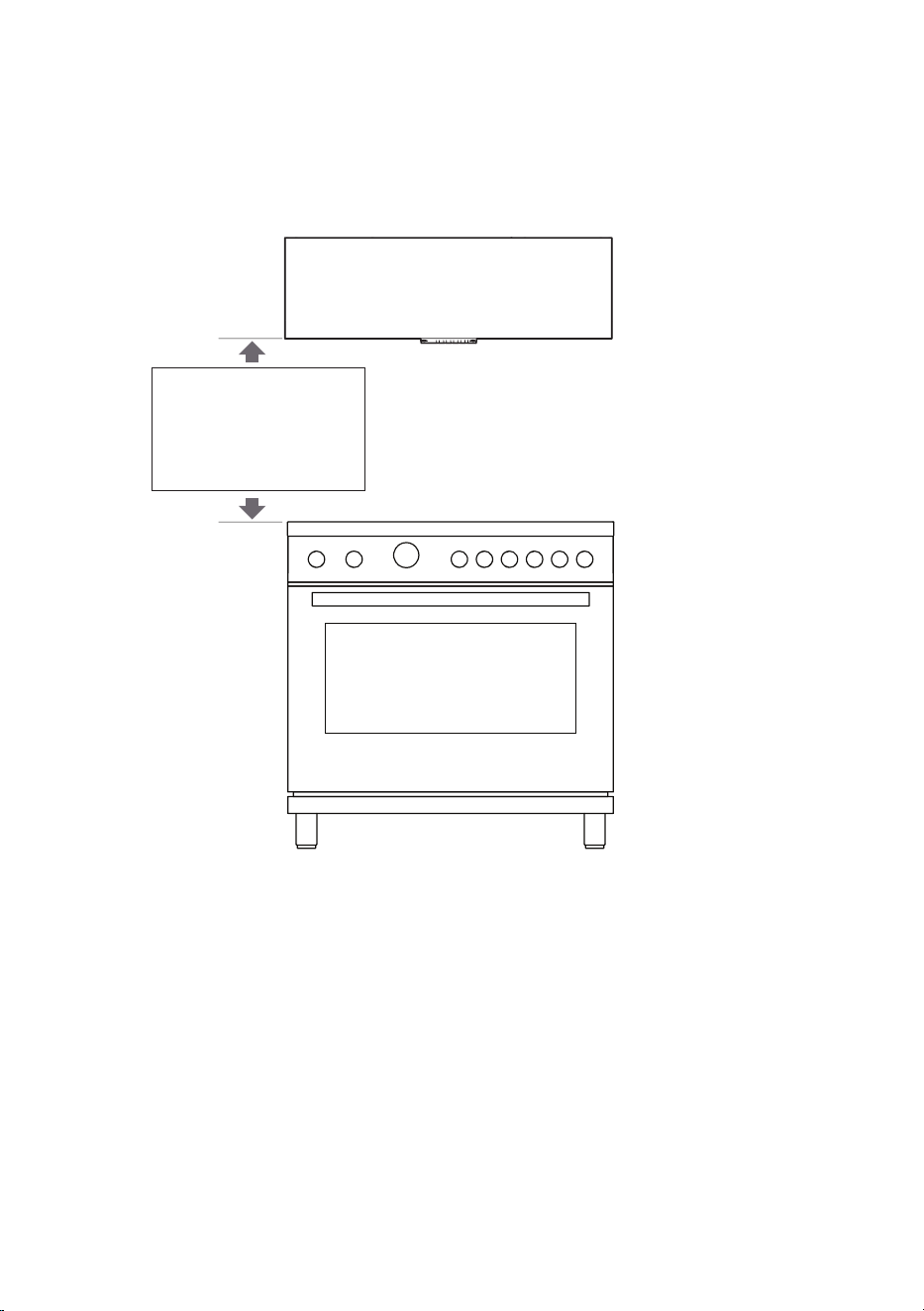
27”to32”
RECOMMENDED
MOUNTING HEIGHT
ABOVE GAS AND
ELECTRIC COOKTOPS
highs and lows
All range hoods have a recommended range of installation height over the cooking
surface.
It is important to install the hood at the proper mounting height. Hoods mounted too
low could result in heat damage and fire hazard; while hoods mounted too high will
be hard to reach and will lose its performance and efficiency.
WIDTH
16-3/8"

- 13 -
27”to32”
WIDTH
1
2
-
7
/8"
MODEL
XOI3015SC
XOI3315SC
WIDTH
26-1/2”
32-1/2”
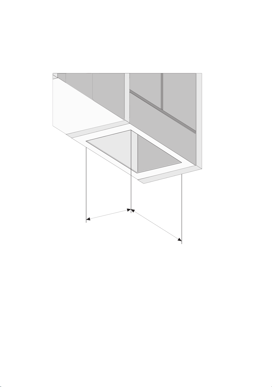
To install the hood into a custom canopy or cabinet, refer to the cutout dimensions
above for your particular model. Gap around the unit should be minimized (~ 1/16”)
to ensure a snug fit.
the cut out
- 14 -
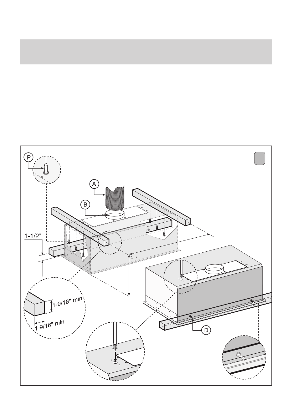
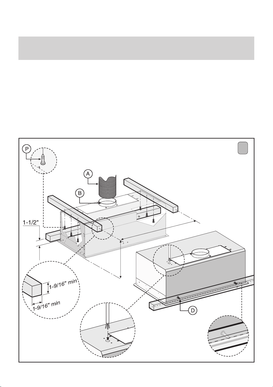
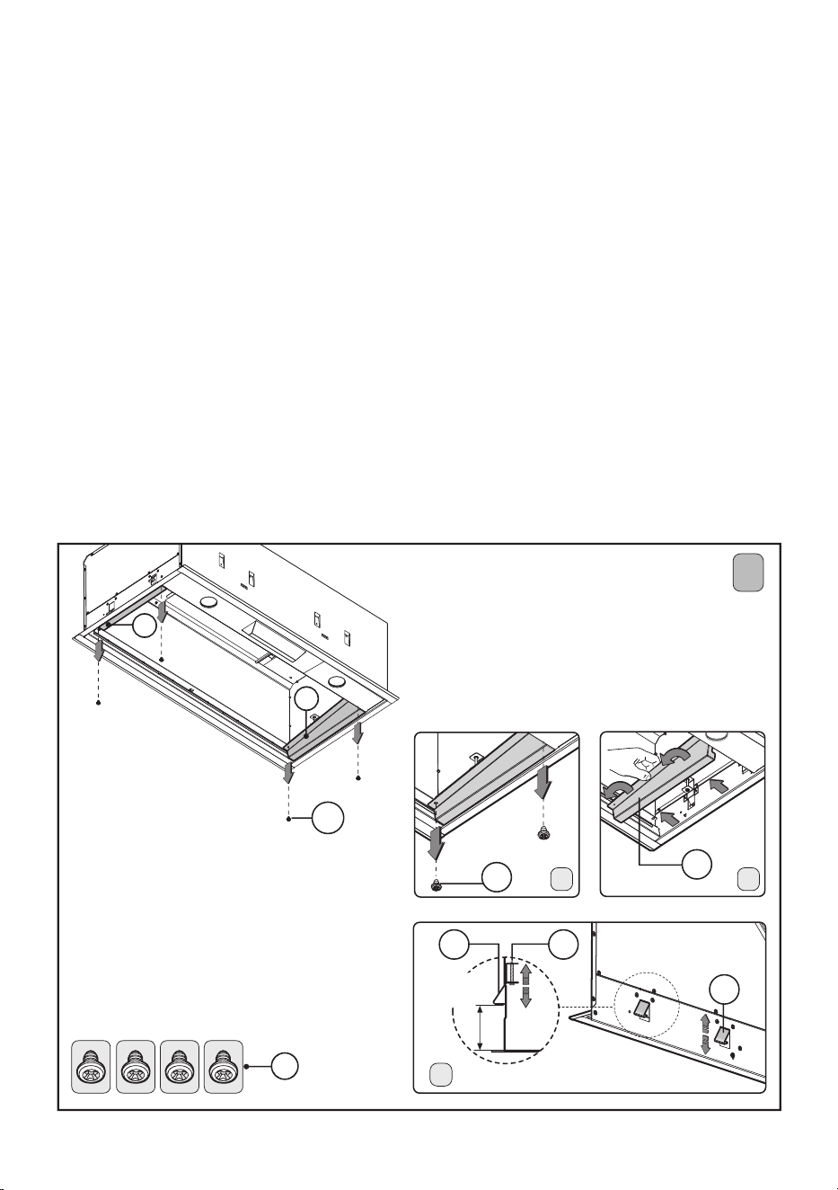
installation
24-1/4” - 30-1/4”
11-9/16”
This product can be installed in 2 different ways:
1) Fixing of the hood with wood framework (Fig.1).
2) Fixing of the hood in the lower part of the kitchen cabinet (Fig.2-3-4-5).
1• Fixing of the hood with wood framework:
When fitting the hood use screws that are suitable for the type of cabinet to which the
appliance is being fixed, following the corresponding holes and fully respecting the
measurements indicated. When fixing the hood in place make sure a wooden frame (not
supplied) is fitted inside the cabinet.
Fix the appliance in place using the 6 screws P and then fit the two safety screws D.
IMPORTANT - The range hood must be secured to wall studs or use drywall
anchors capable of supporting 75 lbs.
1
- 15 -
installation continued
24-1/4” - 30-1/4”
11-9/16”
B
H
A
E
Min - 0-1/2"
Max - 1-0/16"
C
F
F
D
E
B
B
E
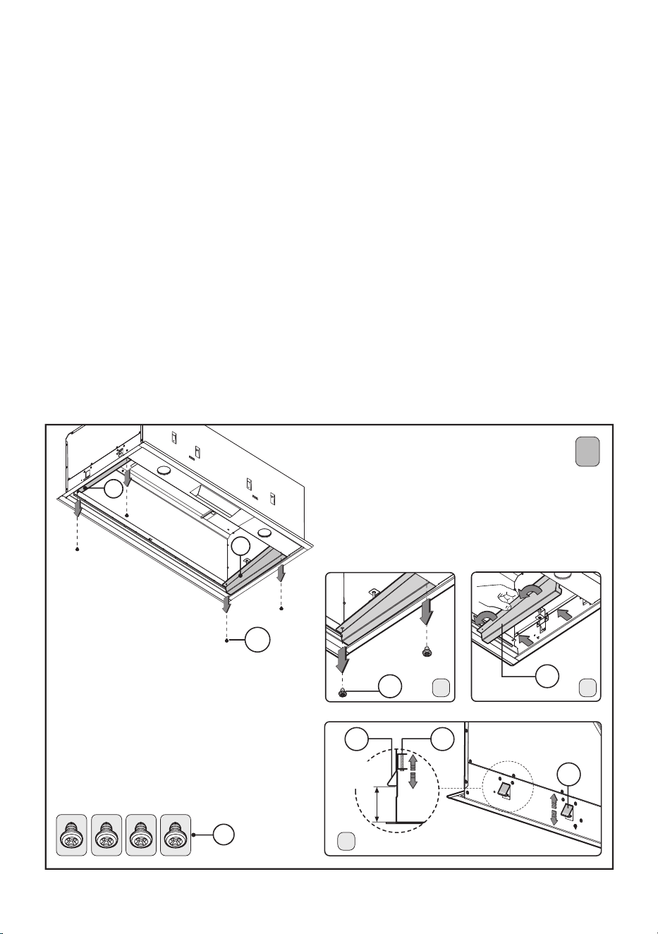
2• Fixing of the hood in the lower part of the kitchen cabinet:
Fo r all measurements relating to the cooker hood, please refer to pag.11.
Before fixing the cooker hood to the lower part of the cabinet, the following steps should
be performed:
1. Remove the 4 screws E fixing the two cooker hood brackets H (RHS and LHS) in place
as indicated in Fig.2A.
2. Remove the brackets H as shown in Fig.2B.
3. Make sure the thickness of the cabinet falls within the range of values listed in Fig.2C.
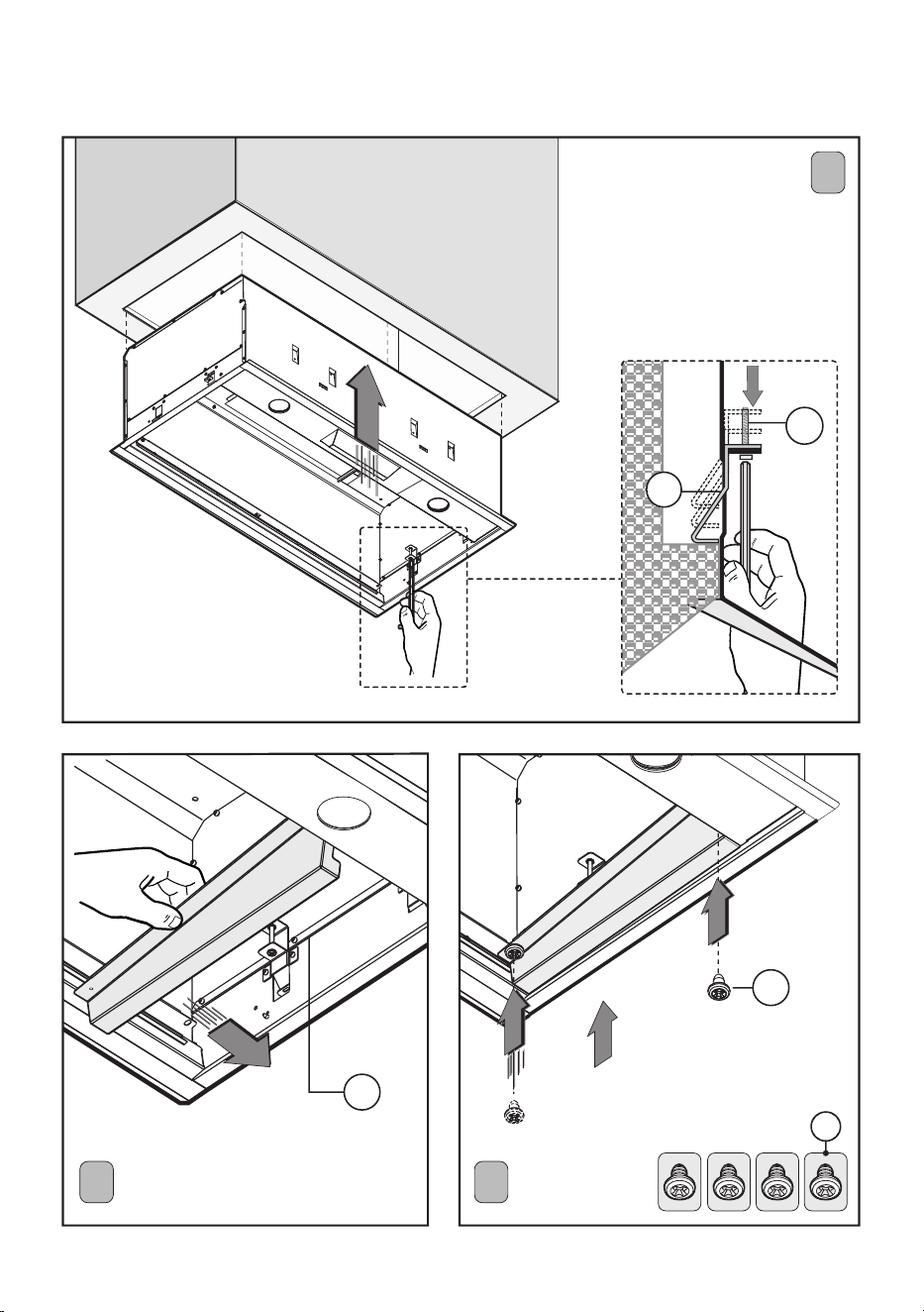
Fit the cooker hood in the cabinet (Fig.3) and make sure the 4 springs are fixed in place
well. Fix the cooker hood to the cabinet securely by using a screwdriver to tighten the
screws M until the appliance is flush with the cabinet. Place again the 2 brackets H (right
and left) of the hood and fix them with the 4 screws E (Fig.4 - Fig.5).
When installed in this way the appliance discharges fumes outside, either through a
perimeter wall or existing ducting.It is therefore necessary to purchase a non-flammable
air exhaust tube A (not supplied) which complies with all current legislation and connect
it to flange B (Fig.1).
2
- 16 -
installation continued
H
E
E
M
F
4 5
3
- 17 -
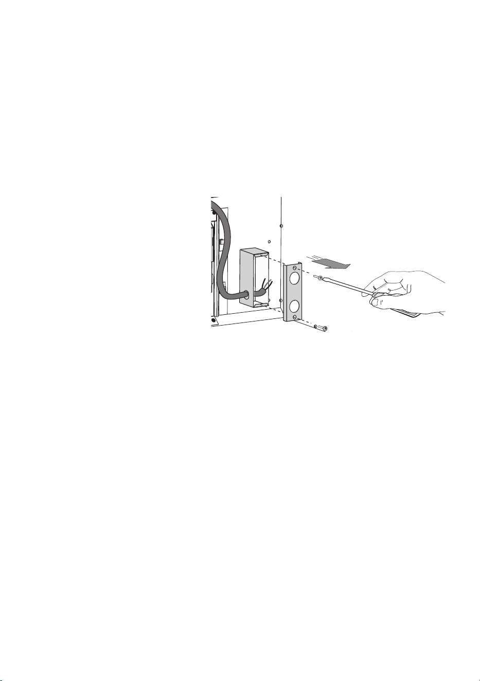
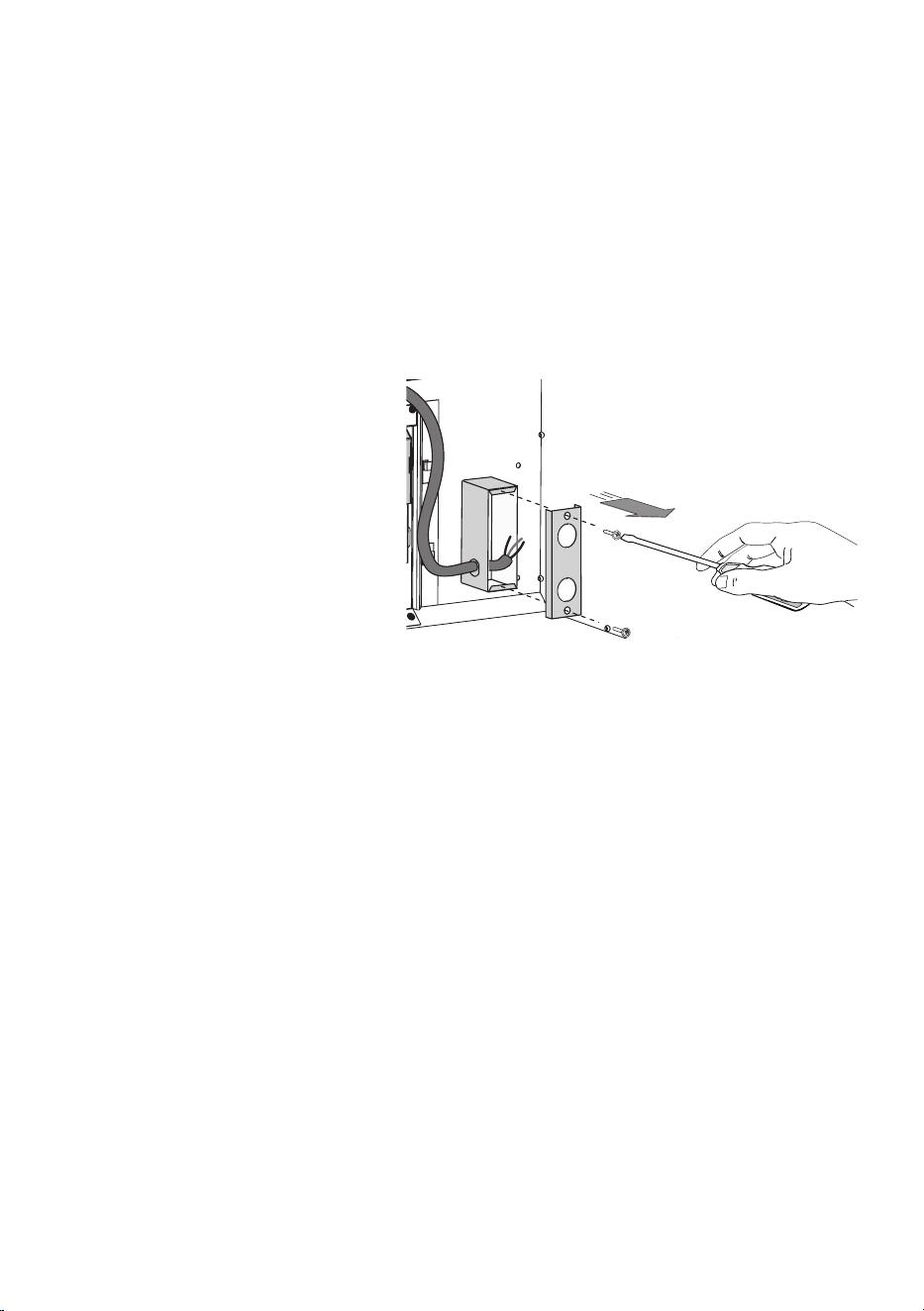
1. Route the power cord to the junction box inside the hood.
2. Using listed conduit fittings and connectors, connect the power supply to the box and each
line to the appropriate wire following this color convention:
BLACK = HOT LEG
WHITE = NEUTRAL
GREEN/YELLOW = GROUND
Polarity must be observed.
Unit must be properly grounded.
Use a double throw disconnect switch.
3. Replace the box cover
4. Replace the Anti-grease Baffles.
All wiring must be in compliance with national electrical code, ANSI/NFPA 70-1999 and all
local codes and regulations.
electrical connection
- 18 -
Regular cleaning and maintenance is the key to long life and peak performance of any
equipment.
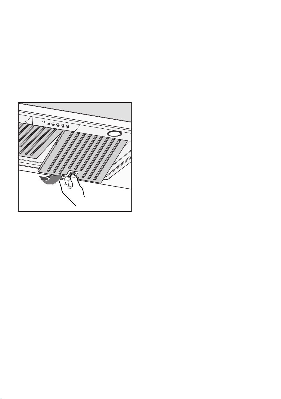
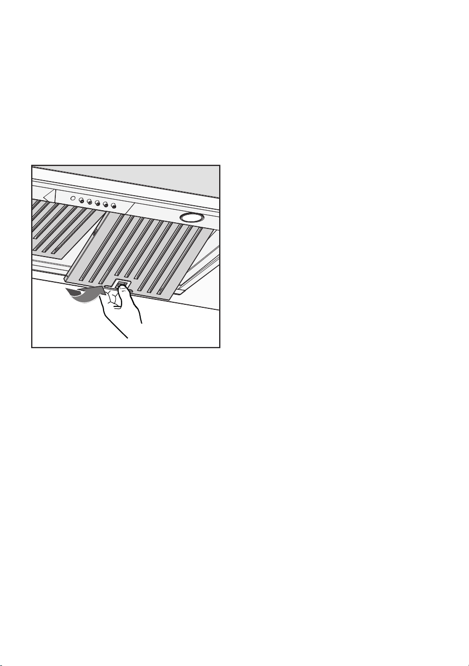
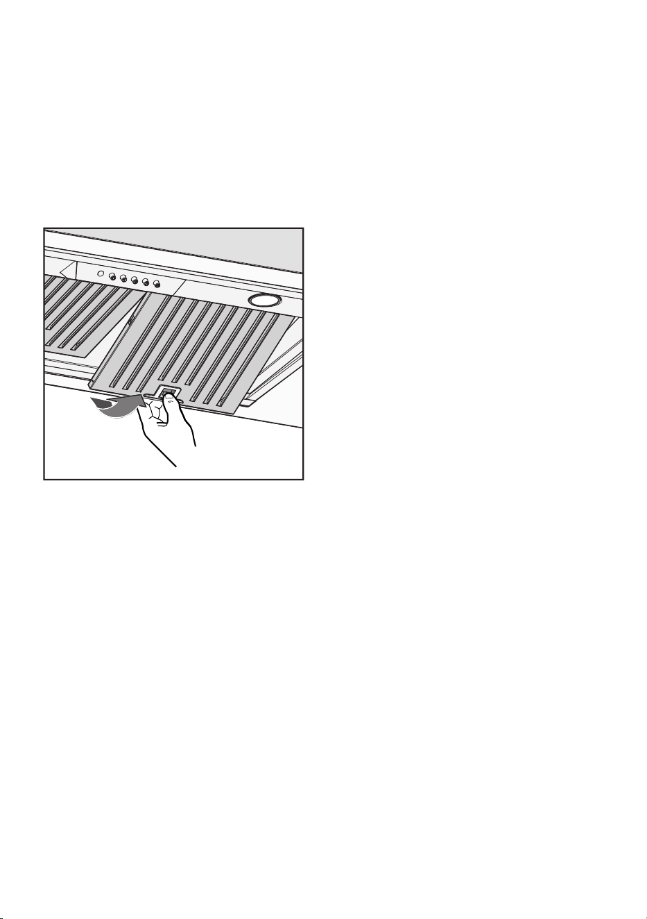
ANTI-GREASE BAFFLE FILTERS: Your XO hood is equipped with stainless steel pro-style
baffle filters designed to capture grease from cooking. The baffles are easily removed for
cleaning either by soaking in a warm, mild dish detergent solution, rinsing thoroughly and
drying - or - by washing in your dishwasher.
TO REMOVE THE BAFFLES:
1.
Pull down on the release latch (shown left)
2.
Lower the front edge of the baffle
3.
Pull forward and remove
4.
To replace, insert the rear of the baffle, holding
the latch open, swing the the front up into place
and release the latch.
The importance of this simple process is es-
sential for two reasons. First to help keep your
kitchen clean and healthy, but it is also critical
to minimize the risk of fire.
Baffle filters should be cleaned at least once every 2 months, more frequently depending on
the type of cooking performed and the build up of grease.
CLEANING STAINLESS STEEL:
Do not use corrosive detergents, abrasive detergents or oven cleaners.
Do not use any product containing chlorine bleach or any product containing chloride.
Do not use steel wool or abrasive scrubbing pads which will scratch and damage surface.
Cleaning Stainless Steel Clean periodically with warm soapy water and clean cotton cloth or
micro fiber cloth. Always rub in the direction of the stainless steel grain. To remove heavier
grease build up use a liquid degreaser detergent. After cleaning use a non-abrasive stainless
steel polish/cleaners, to polish and buff out the stainless luster and grain. Always rub lightly, with
a clean cotton cloth or a micro fiber cloth and buff in the direction of the stainless steel grain.
Any painted surfaces should be cleaned with warm water and detergent only.
maintenance

- 19 -
maintenance continued
XORFND
FOR UNITS USED IN RECIRCULATION MODE ONLY:
This refers to hoods which are not ducted outside but rely instead on carbon filter elements
to help purify the air before it is exhausted back into the room.
The carbon element filters gradually lose efficiency and cannot be cleaned or regenerated.
These must be replaced at least 4 times a year, more frequently if needed based on the
amount of use and style of cooking.
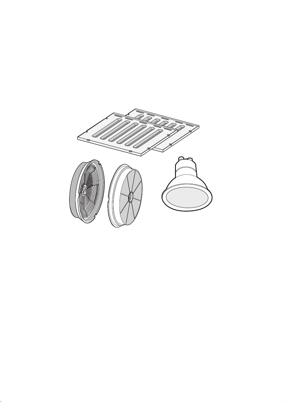
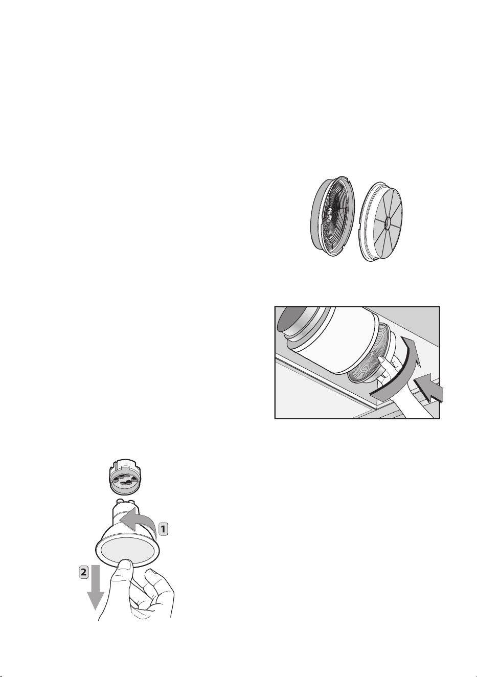
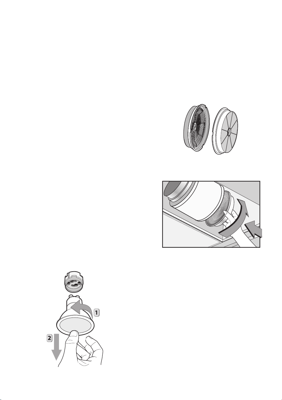
CHANGING THE CARBON FILTERS:
Changing the filters is easy.
To Reduce the Risk of Fire and Shock use only
conversion Kit Model XORFND(ACK0059) Filters.
The XORFND filters are sold in pairs.
To replace the filters, unlatch and remove the
Stainless Steel Anti-Grease Baffles.
This will expose the blower.
One Carbon Filter attaches to each side of the
blower.
Remove the old filter by rotating one quarter turn
counter-clockwise and pull straight away
from the blower.
To install the new filter simply align, push into pla-
ce and rotate one quarter turn clockwise to lock.
LED LIGHT REPLACEMENT
To replace the bulbs, rotate the lamp anticlo-
ckwise as shown in Figure. Replace the bulbs
with new ones of the same type.
XOPSPK6509
(UL REFERENCE ACK0059)
- 20 -
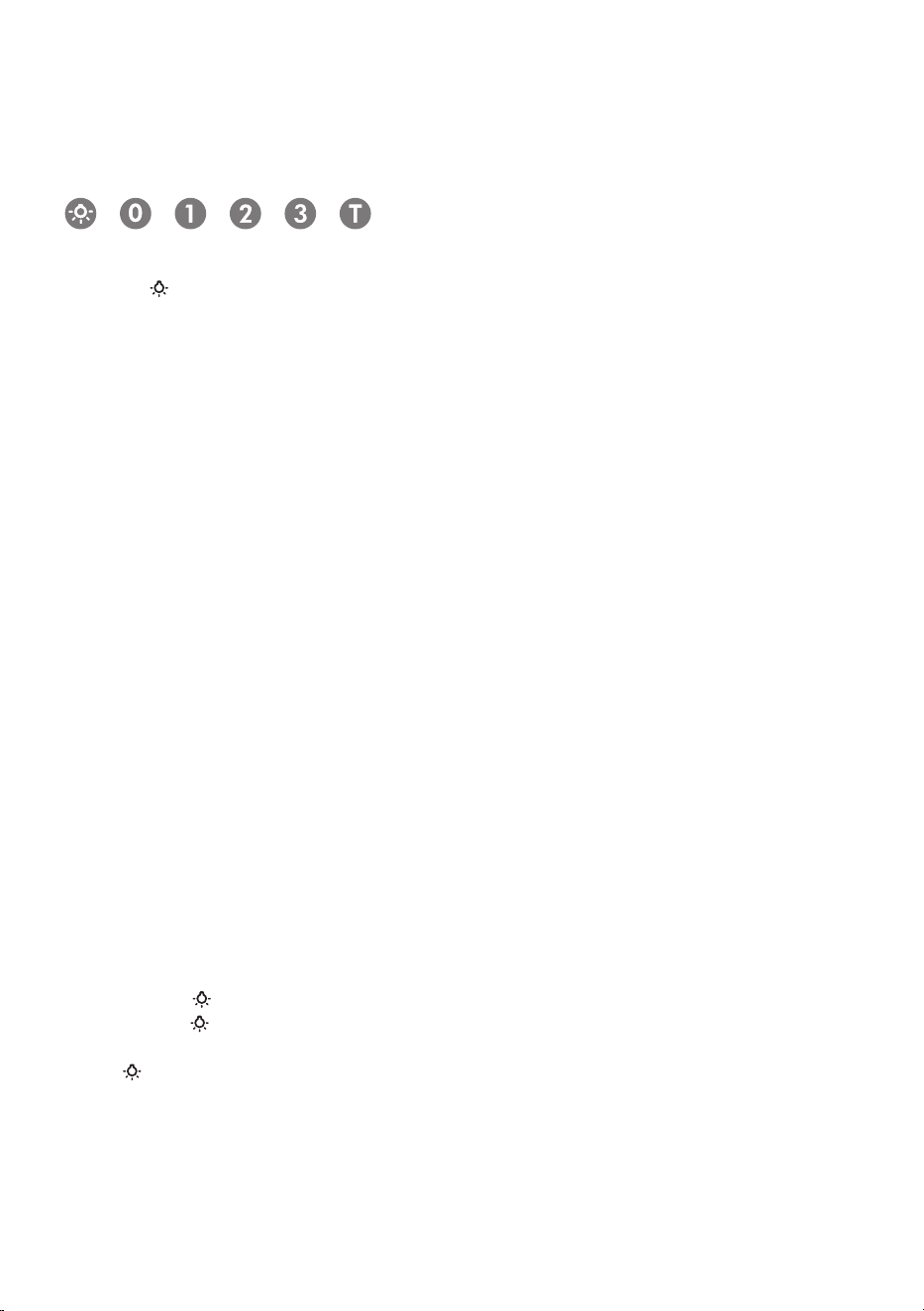
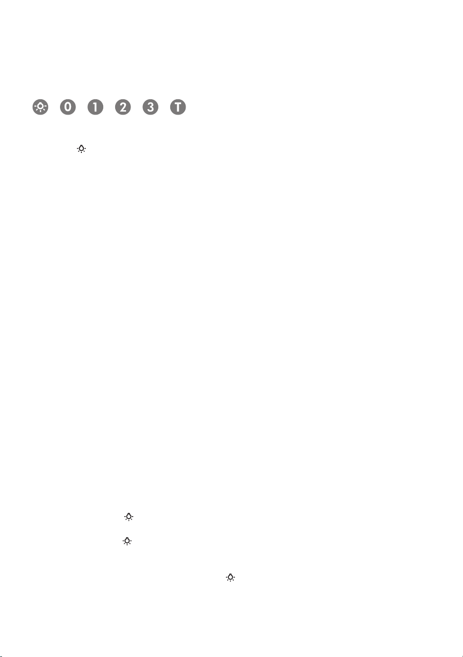
BUTTON : LIGHT
BUTTON 0: OFF
BUTTON 1: SPEED I
BUTTON 2: SPEED II
BUTTON 3: SPEED III
BUTTON T:
AUTOMATIC STOP TIMER - 15 minutes (*)
• The appliance has the Power Boost speed function: press
BUTTON 3
for two seconds and
it will be activated for 10 minutes after which it will return to the previously set speed. When
the function is active the LED ashes. To interrupt it before the 10 minutes have expired press
BUTTON 3
again.
•
By pressing
BUTTON T
for two seconds (with the hood switched o) the “clean air” func-
tion is activated. This function switches the appliance on for ten minutes every hour at
the
rst speed. As soon as this function is activated the motor starts up at the rst speed for ten
minutes. During this time
BUTTON T
and
BUTTON 1
must ash at the same time.
After ten minutes the motor switches o and the LED of
BUTTON T
remains switched on with
a xed light until the motor starts up again at the rst speed after fty minutes and
BUTTON
T
and
BUTTON 1
start to ash again for ten minutes and so on.
By pressing any key for the exclusion of the hood light the hood will return immediately to its
normal functioning (e.g. if
BUTTON 2
is pressed the “clean air” function is deactivated and
the motor moves to the 2nd speed straight away. By pressing the
BUTTON 0
the function is
deactivated).
(*) The “automatic stop timer” delays stopping of the hood, which will continue functioning for
15 minutes at the operating speed set at the time this
function is activated.
• Active
carbon/greaseltersaturation:
-
When button ashes at a frequency of 2 seconds, the grease lters must be cleaned.
-
When button ashes at a frequency of 0.5 seconds, the carbon lters must be replaced.
After the clean lter has been replaced, the electronic memory must be reset by pressing
button
for approximately 5 seconds, until the light on the button stops ashing.
Your XO range hood is controlled by these
electronic push buttons which illuminate when
activated.
easy to operate
Code Compliance Control

- 21 -
Code Compliance Control
New!
Some local codes limit the maximum exhaust airflow of range hoods to 400 CFM
before a Make Up Air System is required.
The XOI3015SC and XOI3315SC models are supplied with 600 CFM capacity.
The CCC system allows you to limit the hood from 600 CFM to 395 CFM.
To set up for 395 CFM Operation - follow the procedure below:
1. After the hood has been powered up initially, disconnect the power supply by shutting
off the circuit breaker.
2. VERY IMPORTANT, after turning power back on to the unit, you must press and hold
both the
and “0” buttons simultaneously within 5 seconds of re-powering the unit.
NOTE: If you do not press the buttons within the first 5 seconds after turning power back
on to the hood - the CCC function will not engage and you must repeat from Step 1.
3. The control blinks 3 times
4. The hood is now configured at 395 CFM - the POWER BOOST function is also
disabled.
5. Affix the sticker supplied to indicate the unit has been reconfigured to a maximum
air flow of 395 CFM.
6. Once reconfigured for 395 CFM, the unit cannot be reset to 600 CFM.
make up air conversion
- 22 -
RECIRCULATION KITS
FILTERS
REPLACEMENT LIGHTS
REMOTE CONTROLS
DUCT COVERS
REPLACEMENT SWITCHES
BLOWER MOTORS
FAN WHEELS
ALL OF THESE PARTS AND MORE ARE AVAILABLE, SIMPLY
VISIT WWW.XOAPPLIANCE.COM and click on PARTS STORE
OR CALL US AT 973-403-8900
access parts & accessories

- 23 -
YEAR
WARRANTY
2
PARTS + LABOR
90 DAY LOVE IT or LEAVE IT. For 90 Days all our products are backed by our unique Love it or Leave it Guarantee.
TWO-YEAR PARTS & LABOR LIMITED WARRANTY. XO warrants to the original purchaser of every new XO ventilation
unit, the cabinet and all parts thereof, to be free from defects in material or workmanship under normal and proper use and
maintenance as specified by XO and upon proper installation and start-up in accordance with the instruction packet supplied
with each XO unit. XO’s obligation under this warranty is limited to a period of two (2) years from the date of original purchase.
WARRANTY CLAIMS. All claims for labor or parts must be made directly through XO. All claims should include: model number
and serial number of cabinet, proof of purchase, and date of installation. In case of warranted compressor, the compressor
model tag must be returned to XO along with the above listed information.
WHAT IS NOT COVERED BY THIS WARRANTY. XO’s sole obligation under this warranty is limited to either repair
or replacement of parts, subject to the additional limitations below. This warranty neither assumes nor authorizes any person
to assume obligations other than those expressly covered by this warranty. Open box, factory seconds, scratch and dent, floor
models and commercial applications are excluded from these warranties.
WARRANTY IS NOT TRANSFERABLE. This warranty is not assignable and applies only in favor of the original purchaser/
user at the original installation location. Any such assignment or transfer shall void the warranties herein made and shall void
all warranties, express or implied, including any warranty or merchantability or fitness for a particular purpose.
IMPROPER USAGE. XO assumes no liability for parts or labor coverage for component failure or other damages resulting from
improper usage or installation or failure to clean and/or maintain product as set forth in the warranty packet provided with the unit.
ALTERATION OR NEGLECT. XO is not responsible for the repair or replacement of any parts that XO determines have been
subjected after the date of manufacture to alteration, neglect, abuse, misuse, accident, damage during transit or installation,
fire, flood, or act of God.
IMPROPER ELECTRICAL CONNECTIONS. XO is not responsible for the repair or replacement of failed or damaged
components resulting from electrical power failure, high or low voltage, use of extension cords, or improper grounding of the unit.
YOUR RIGHTS UNDER STATE LAW. This warranty gives you specific legal rights and you may have other rights that
vary from state to state. Some states do not allow the exclusion or limitation of consequential damages or a limitation on how
long an implied warranty lasts, so the above exclusion or limitation may not apply to you.
OUTSIDE U.S. This warranty does not apply to, and XO is not responsible for, any warranty claims made on products sold
or used outside the 48 continental United States.
To obtain service:
Call 973-403-8900 |email ser[email protected] | or submit a request on our website
www.xoappliance.com
we’ve got your back

J’ai travaillé très
dur sur ce manuel -
veuillez donc le lire...
XOI INSÉRER | POWER PACK
MODÈLES XOI3015SC, XOI3315SC

- 25 -
Lorsque vous achetez un appareil XO
vous pouvez être sûr que vous avez choisi un
produit de haute qualité, innovant et élégant
d'une entreprise qui se soucie de vous
!
Si vous avez besoin d'un service ou si vous avez des
questions, il existe 2 façons de contacter nos experts en
ventilation
;
En ligne @ https://xoappliance.com/priority-service-for-your-xo-
-product/Ou par téléphone 973-403-8900
FÉLICITATIONS
pour l'achat de votre XO.
Avant de continuer, prenez un
instant pour enregistrer votre XO à
l’adresse
:
www.xoappliance.com/register-your-product/
L'INSCRIPTION VOUS AIDE EN -
Assurant la couverture de garantie si vous avez besoin d'un
service. Vérifiant la propriété à des fins d'assurance XO vous
avertit en cas de changement de produit ou de rappel.

- 26 -
C’est pour
votre bien...
Honnêtement.
veuillez lire et suivre
toutes les consignes de
sécurité
où sont les choses
SE PRÉPARER
Sécurité et précautions
Planification des conduits
Exemples d’installation
Dimensions
L’INSTALLATION
Hauteur de montage
Dimensions de découpe
Installation
Connexions électriques
ENTRETIEN
Filtres
Nettoyage
Recirculation
Remplacement de la lumière
FONCTIONNEMENT
Commandes du bouton-poussoir
Conversion d’air d’appoint CCC
PIÈCES et GARANTIE
42 - 43
44 - 45
27 - 33
34 - 39
40 - 41
- 27 -
INSTRUCTIONS DE SECURITE IMPORTANTES
POUR UN USAGE DOMESTIQUE EXCLUSIVEMENT
LIRE ET CONSERVER LES INSTRUCTIONS
COMMENCER PAR LIRE ENTIEREMENT LES INSTRUCTIONS.
IMPORTANT: Conserver les Instructions à usage des Inspecteurs Electriques Locaux.
A L’ATTENTION DE L’INSTALLATEUR: Laisser les Instructions dans l’unité à usage du
propriétaire.
A L’ATTENTION DU PROPRIETAIRE: Conserver les Instructions pour des consultations
ultérieures.
N’utiliser des produits de nettoyage ou des détergents qu’avec la plus grande
prudence.
Cet appareil est propre à une utilisation domestique et culinaire.
AVERTISSEMENT – Afin de réduire les risques d’incendie ou d’électrocution, ne pas
utiliser le moteur avec un Dispositif de Contrôle de la Vitesse à Semi-conducteurs
quel qu’il soit.
ATTENTION – Afin de réduire les risques d’incendie et de permettre une aspiration
correcte de l’air, s’assurer que celui-ci est bien transporté à l’extérieur à travers un
conduit d’évacuation. – Ne pas évacuer l’air dans des interstices tels qu’entre des
cloisons ou des plafonds, dans des greniers, des espaces confinés ou des garages.
ATTENTION – N’utiliser que pour une ventilation générique. Cet appareil n’est pas
propre à l’aspiration de matières ou de vapeurs dangereuses ou explosives.
ATTENTION – Afin d’éviter des bruits et des dommages au niveau du moteur, et/ou
un déséquilibre au niveau des hélices, veiller à ce que l’unité d’alimentation n’entre
pas en contact avec du spray, de la poussière etc.
ATTENTION – Pour obtenir des compléments d’informations, consulter l’étiquette de
spécification sur le produit.
AVERTISSEMENT – AFIN DE RÉDUIRE LES RISQUES D’INCENDIE, D’ÉLECTROCUTION
OU DE DOMMAGES AUX PERSONNES, RESPECTER LES REGLES SUIVANTES:
A. N’utiliser l’unité que pour les opérations prévues par le fabricant. Pour toute question
éventuelle, contacter le fabricant.
B. Avant d’effectuer des opérations de maintenance ou de nettoyage sur l’unité,
débrancher le panneau de service et fermer à clef les commandes de déconnection
la sécurité d’abord

- 28 -
afin d’éviter toute mise sous tension accidentelle.
Au cas où les commandes de déconnection ne pourraient être fermées à clef, fixer sur
lepanneau de service un message avertissant du danger, par exemple une plaque.
AVERTISSEMENT – AFIN DE RÉDUIRE LES RISQUES D’INCENDIE PAR
INFLAMMATION DES GRAISSES PRESENTES SUR LA GAZINIERE:
A. Ne jamais laisser de casseroles sur feu vif sans surveillance. D’éventuels débordements
dus à une forte ébullition peuvent provoquer de la fumée et des dépôts de graisses
susceptibles de prendre feu. Réchauffer l’huile lentement, à petit feu ou moyen.
B. ALLUMER systématiquement la hotte pour cuisiner à des températures élevées ou
pour flamber des aliments (ex. : Crêpes Suzette, Cherries Jubilee – cerises flambées
au brandy et glace -, Boeuf flambé au poivre).
C. Nettoyer souvent le moteur. Eviter que les graisses ne s’accumulent sur le moteur ou
sur le filtre.
D. Utiliser des plats aux dimensions adaptées. Toujours utiliser des ustensiles de cuisine
adaptés à la taille de la casserole qui se trouve sur la cuisinière.
E. Veiller à ce que le moteur, les filtres et la surface où viennent s’accumuler les graisses
restent propres.
F. N’utiliser une flamme élevée que lorsque cela est nécessaire. Réchauffer l’huile
lentement, à faible ou moyenne température.
G. Ne jamais laisser la cuisinière sans surveillance pendant la cuisson.
H. Utiliser systématiquement des ustensiles de cuisine adaptés au type et à la quantité
d’aliments que l’on prépare.
AVERTISSEMENT – AFIN DE RÉDUIRE LES RISQUES DE DOMMAGES AUX PERSONNES
EN CAS D’INCENDIE PAR INFLAMMATION DES GRAISSES PRESENTES SUR LA
CUISINIERE, RESPECTER LES REGLES SUIVANTESa:
A. ETOUFFER LA FLAMME à l’aide d’un couvercle hermétique, une plaque à four ou un
plateau en métal et éteindre le brûleur. PROCEDER AVEC LA PLUS GRANDE PRUDENCE
AFIN D’EVITER TOUTE BRULURE. Si les flammes ne s’éteignent pas immédiatement,
EVACUER LA PIECE ET APPELER LES POMPIERS.
B. NE JAMAIS TOUCHER UN PLAT EN FEU – on risque de se brûler.
C. NE PAS UTILISER D’EAU, ni de chiffons ou de serviettes humides – cela pourrait
provoquer une violente explosion de vapeur.
D. Utiliser un extincteur UNIQUEMENT dans les cas suivants:
1. On dispose d’un extincteur de Classe ABC que l’on sait faire fonctionner.
2.
L’incendie est peu important et il est confiné à la zone où il a éclaté.
3. On a déjà appelé les pompiers.
4. On peut affronter les flammes tout en ayant une issue de secours derrière soi.
aBasé sur les « mesures de sécurité incendie dans la cuisine « publiées par l’organisme
NFPA.

- 29 -
Une bonne maintenance de la hotte garantit le parfait fonctionnement de l’unité.
INSTRUCTIONS D’INSTALLATION
AVERTISSEMENT – AFIN DE RÉDUIRE LES RISQUES D’INCENDIE, D’ÉLECTROCUTION
OU DE DOMMAGES AUX PERSONNES, RESPECTER LES REGLES SUIVANTES:
A. Les opérations d’installation et de branchement électrique doivent être effectuées
par du personnel qualifié, conformément aux lois et aux normes en vigueur, y compris
celles relatives aux appareils à feu.
B. Il est nécessaire de disposer d’une quantité d’air suffisante pour une bonne
combustion et aspiration des gaz à travers le conduit de fumée de l’installation de
combustion du carburant, afin d’éviter un appel d’air de l’arrière. Suivre les indications
du fabricant de l’installation de chauffage et les normes de sécurité correspondantes
telles que celles émises par l’Association Nationale de Protection contre les Incendies
(National Fire Protection Association - NFPA), la Société Américaine des Techniciens
de Chauffage, Réfrigération et Climatisation de l’Air (American Society for Heating,
Refrigeration and Air Conditioning Engineers - ASHRAE), et par les autorités locales
préposées.
C. Au cours des opérations de découpage ou de perforation du mur ou du plafond,
veiller à ne pas endommager les câbles électriques ou d’autres canalisations cachées.
D. L’appareil doit toujours être relié à un trou d’évacuation vers l’extérieur.
E. L’unité doit être reliée à la terre.
AVERTISSEMENT – AFIN DE RÉDUIRE LES RISQUES D’INCENDIE, N’UTILISER QUE
DESCONDUITS METALLIQUES
AVERTISSEMENT – LES APPAREILS ELECTROMENAGERS PEUVENT PARFOIS S’AVERER
DANGEREUX.
A. Ne pas contrôler les filtres lorsque la hotte est en état de marche.
B. Ne pas toucher les lampes après une utilisation prolongée de l’appareil.
C. Ne jamais faire flamber d’aliments sous la hotte.
D. L’usage de flammes libres est dangereux pour les filtres et peut générer des incendies.
E. Contrôler constamment les fritures pour éviter que des éclaboussures d’huile ne
prennent feu.
F. Avant d’effectuer toute opération de maintenance, débrancher la hotte du réseau
d’alimentation électrique.
Le fabricant ne pourra être retenu responsable d’éventuels dommages causés par le
non respect des instructions susmentionnées.

- 30 -
CETTE HOTTE EST CONÇUE POUR UTILISER UN CONDUIT ROND DE 6 PO -
IL PEUT ÊTRE TRANSITIONNÉ EN UN CONDUIT RECTANGULAIRE 3-1 / 4 po X 10 po
NE JAMAIS RÉDUIRE LA TAILLE DU CONDUIT. LES CONDUITS SOUS-DIMENSIO-
NNÉS RESTREIGNENT CONSIDÉRABLEMENT LE DÉBIT D'AIR ET NUISENT AUX
PERFORMANCES.
(Exemple
: la surface d'un conduit de 6 po est plus de DEUX fois supérieure à celle
d'un conduit de 4 po)
GARDER LES CONDUITES AUSSI COURTES ET DROITES QUE POSSIBLE.
ÉVITEZ D'UTILISER DES CONDUITS MÉTALLIQUES FLEXIBLES SI LA LONGUEUR
EST SUPÉRIEURE À 6 pi.
N'UTILISEZ JAMAIS DE CONDUITS EN PLASTIQUE.
UTILISER UN CONDUIT MÉTALLIQUE À ALÉSAGE LISSE.
MINIMISER LE NOMBRE DE RACCORDS (voir tableau).
LORSQUE VOUS DEVEZ UTILISER DES RACCORDS, ESSAYEZ DE LES SÉPARER
AVEC DES SECTIONS DE 3 pi OU PLUS DE CONDUIT DROIT.
SUIVEZ TOUJOURS LES DIRECTIVES DU FABRICANT POUR L'ÉQUIPEMENT DE
CUISSON QUE VOUS VENTILEZ.
SI DES AMORTISSEURS DE COMMANDE D'AIR SONT NÉCESSAIRES, POSITIONNEZ
LE CAPTEUR DANS UN CONDUIT EN LIGNE DROITE IDÉALEMENT AVEC UN CON-
DUIT EN LIGNE DROITE DE 3 pi ENTRE CHAQUE CÔTÉ DU CAPTEUR ET UN RAC-
CORD DE CONDUIT. N'OUBLIEZ PAS D'INCLURE LE CÂBLAGE D'ALIMENTATION
ET DE COMMANDE DANS VOS PLANS.
RESPECTEZ TOUS LES CODES ET DÉCRETS LOCAUX DU BÂTIMENT.
UTILISEZ LA FEUILLE DE TRAVAIL QUI SUIT POUR VOUS AIDER À CALCULER LE
TOTAL DES PIEDS ÉQUIVALENTS DE VOTRE CONDUIT.
LE TOTAL DES PIEDS ÉQUIVALENTS DOIT ÊTRE INFÉRIEUR À 100 pi.
quelques règles simples pour pla-
nifier votre canalisation
1
1
12
7
14
8
33
2
4
24
24
33
- 31 -
1
1
12
7
14
8
33
2
4
24
24
33
LE FAIT DE PROVOQUER UN CHANGEMENT DE DIRECTION DE L'AIR PROVOQUE DES
TURBULENCES ET RESTREINT LE DÉBIT DANS UN SYSTÈME.
SI VOUS UTILISEZ UN CONDUIT MÉTALLIQUE FLEXIBLE - AUGMENTEZ TOUS LES MULTI-
PLICATEURS DE 50 % (12 DEVIENT 18 - ETC.)
CETTE FEUILLE DE CALCUL FACILE À UTILISER EST POUR 600 MÈTRES CUBES PAR MI-
NUTE OU MOINS.
SOUS « QTÉ UTILISÉE », ENTREZ LE MODE D'UTILISATION DE CHAQUE SECTION.
DANS LES DEUX PREMIÈRES LIGNES - ENTREZ LE NOMBRE DE PIEDS DE CHAQUE TYPE
DE CONDUIT DROIT QUE VOUS UTILISEREZ (C.-À-D. POUR 20 PI, ENTREZ 20, POUR 30
PI, ENTREZ 30).
SAISISSEZ LE NOMBRE DE CHAQUE TYPE DE COURBE QUE VOUS UTILISEZ ET LE TYPE
DE CAPUCHON D'EXTRÉMITÉ OF.
MULTIPLIEZ SUR CHAQUE LIGNE LE « MULTIPLICATEUR » X « QUANTITÉ UTILISÉE » POUR
OBTENIR LES PIEDS ÉQUIVALENTS POUR CES COMPOSANTS.
AJOUTEZ TOUTES LES VALEURS DANS LA COLONNE « PIEDS ÉQUIVALENTS ».
PIÈCE DE
CONDUIT
DESCRIPTION MULTIPLICA-
TEUR
QTÉ
UTILISÉE
PIEDS
ÉQUIVALENTS
Conduit rond de 1 pi sur 6 po
1 pi de conduit rectangulaire
3 1/4 po x 10 po
Coude de 6 po à 90 degrés
Coude de 6 po à 45 degrés
3 1/4 po x 10 po à 90 degrés
3 1/4 po x 10 po à 45 degrés
3 1/4 po x 10 po côté 90
degrés
Rond 3 1/4 po x 10 po x 6 po
3 1/4 po x 10 po x 6 po à 90
degrés
Capuchon mural rond de 6
po avec amortisseur
Capuchon mural de 3 1/4 po x
10 po avec amortisseur
Capuchon de toit rond de
6 po
LE TOTAL DES PIEDS ÉQUIVALENTS DOIT ÊTRE INFÉRIEUR À 100
estimation des pieds équivalents
totaux dans un conduit

- 32 -
VENTILÉRECIRCULATION
ÉVENT D’ÉCHAPPEMENT
MURAL
ÉVENT D’ÉCHAPPEMENT
DE TOIT
ÉVENT D’ÉCHAPPEMENT DE
SOFFITE
ÉVENT D’ÉCHAPPEMENT
SUPÉRIEUR DE L'ARMOIRE
L'ÉCHAPPEMENT DE RECIRCULATION DOIT ÊTRE
RETOURNÉ DANS L'ESPACE
exemples d'installation typiques
- 33 -
2-1/16"2-1/16"
1-1/16"
4-1/4"4-1/4"
1-3/16"
12-5/8"
15"
Ø 6"
11-1/2"
15/16"
“A”
1-1/4"
“C”
“B”
Ø6"
› Devant de la hotte › Côté de la hotte
› Haut de la hotte
dimensions
Coupure de la
CONNEXION
ÉLECTRIQUE
MODÈLE A B C
XOI3015SC
26-3/8”
18-1/2” 27-3/4”
XOI3315SC
32-3/8”
24-1/2” 33-3/4”
- 34 -
27”to32”
HAUTEUR DE MONTA-
GE RECOMMANDÉE
AU-DESSUS DES PLA-
QUES DE CUISSON AU
GAZ ET ÉLECTRIQUES
hauts et bas
Toutes les hottes de cuisinière ont une plage de hauteur d'installation recommandée
sur la surface de cuisson.
Il est important d'installer la hotte à la bonne hauteur de montage. Les hottes mon-
tées trop bas peuvent entraîner des dommages causés par la chaleur et un risque
d'incendie ; tandis que les hottes montées trop haut seront difficiles à atteindre et
perdront leurs performances et leur efficacité.

- 35 -
27”to32”
WIDTH
1
2
-
7
/8"
MODÈLE
XOI3015SC
XOI3315SC
LARGEUR
LARGEUR
26-1/2”
32-1/2”
Pour installer la hotte dans un auvent ou une armoire personnalisée, reportez-vous
aux dimensions de découpe ci-dessus pour votre modèle particulier. L'espace autour
de l'unité doit être minimisé (~ 1/16 po) pour assurer un ajustement parfait.
la découpe
- 36 -
installation
24-1/4” - 30-1/4”
11-9/16”
1
On peut installer ce produit dans deux manières differentes:
1) Fixer la hotte avec le montage en bois (figure 1).
2) Fixer la hotte dans la partie inférieure de l’élément haut (figure 2-3-4-5).
1• Fixer la hotte avec le montage en bois:
Utilisez des vis de fixation adaptées au type de meuble, percez les trous en respectant
les cotes indiquées.
Pour fixer la hotte, placez un renfort en bois (PAS FOURNI AVEC L’APPAREIL) à l’intérieur
du meuble de cuisine.
Fixez l’appareil à l’aide des 6 vis P, et procédez à la fixation de sécurité à l’aide des 2 vis D.
IMPORTANT: La hotte doit être fixée au mur avec des pivots de support filetés ou
des chevilles d’une capacité de 75 livres.

- 37 -
suite de l’installation
24-1/4” - 30-1/4”
11-9/16”
B
H
A
E
Min - 0-1/2"
Max - 1-0/16"
C
F
F
D
E
B
B
E
2
2• Fixer la hotte dans la partie inférieure de l’ élément haut:
Pour les dimensions d’encombrement de la hotte, consulter la pag.33.
Avant de fixer la hotte au-dessous du meuble, effectuer les opérations suivantes:
1. Retirer les 4 vis E qui fixent les deux étriers de fixation H (de drte et de gche) de la hotte
comme illustré figure 2A.
2. Retirer les étriers de fixation H comme illustré figure 2B.
3. Veiller à ce que l’épaisseur du meuble soit bien comprise entre les dimensions
indiquées figure 2C.
Insérer la hotte à l’intérieur du meuble (Fig.3) en veillant à ce que les 4 ressorts soient
bien encastrés.
Fixer définitivement la hotte au meuble à l’aide des vis M prévues qu’il faut visser avec un
tournevis jusqu’à ce que l’appareil vienne en butée contre le meuble).
Repositionner les deux étriers H (dx et sx) de la hotte et les fixer avec les 4 vis E (figure
4-5).
Grâce à ce type d’installation, l’appareil évacue les vapeurs de cuisson à l’extérieur à
travers un mur de l’habitation ou dans un conduit préexistant. Il faut donc se munir d’un
tuyau d’évacuation de l’air A (non fourni) non inflammable, du type préconisé par les
normes en vigueur et le raccorder à la bride B (Fig.1).

- 38 -
suite de l’installation
H
E
E
M
F
4 5
3

- 39 -
1. Acheminez le cordon d'alimentation vers la boîte de jonction à l'intérieur de la hotte.
2. À l'aide des raccords et connecteurs de conduit répertoriés, connectez l'alimentation à la
boîte et chaque ligne au fil approprié en suivant cette convention de couleur
:
NOIR = PIED CHAUD
BLANC = NEUTRE
VERT/JAUNE = SOL
La polarité doit être observée.
L'unité doit être correctement mise à
la terre.
Utilisez un interrupteur de déconnexion
à double jet.
3. Remplacez le couvercle de la boîte
4. Remplacez les filtres à chicanes
anti-graisse.
Tout le câblage doit être conforme au code électrique national, ANSI/NFPA 70-1999 et à tous
les codes et réglementations locaux.
connexion électrique
- 40 -
maintenance
Le nettoyage et la maintenance réguliers sont la clé d'une longue durée de vie et des perfor-
mances de pointe de tout équipement.
FILTRES À CHICANES ANTI-GRAISSE : Votre hotte XO est équipée de filtres à chicanes
en acier inoxydable de style pro conçus pour capturer la graisse de la cuisson. Les filtres à
chicanes sont facilement amovibles pour le nettoyage soit en les trempant dans une solution
de détergent à vaisselle douce et chaude, en les rinçant soigneusement et en les séchant -
soit en les lavant au lave-vaisselle.
POUR RETIRER LES FILTRES À CHICA-
NES
:
1. Tirez vers le bas sur le loquet de déverrou-
illage (illustré à gauche)
2. Abaissez le bord avant du filtre à chicanes
3. Tirez vers l'avant et retirez
4. Pour le remplacer, insérez l'arrière du filtre
à chicanes, maintenez leloquet ouvert, faites
pivoter l'avant vers le haut pour le mettre en
place et libérez le loquet.
L'importance de ce processus simple est es-
sentielle pour deux raisons. Tout d'abord pour
aider à garder votre cuisine propre et saine,
mais il est également essentiel de minimiser
le risque d'incendie.
Les filtres à chicanes doivent être nettoyés au moins une fois tous les 2 mois, plus fréquem-
ment selon le type de cuisson effectuée et l'accumulation de graisse.
NETTOYAGE DE L’ACIER INOXYDABLE
:
N'utilisez pas de détergents corrosifs, de détergents abrasifs ou de nettoyants pour fours.
N'utilisez aucun produit contenant de l'eau de Javel chlorée ou un produit contenant du
chlorure.
N'utilisez pas de laine d'acier ou de tampons abrasifs qui risquent de rayer et d'endommager
la surface.
Nettoyage de l'acier inoxydable Nettoyez régulièrement avec de l'eau chaude savonneuse
et un chiffon en coton propre ou un chiffon en microfibres. Frottez toujours dans le sens du
grain de l'acier inoxydable. Pour éliminer l'accumulation de graisse plus lourde, utilisez un
détergent dégraissant liquide. Après le nettoyage, utilisez un produit de polissage/nettoyant
pour acier inoxydable non abrasif pour polir et polir le lustre et le grain de l'acier inoxydable.
Frottez toujours légèrement avec un chiffon en coton propre ou un chiffon en microfibres et
polissez dans le sens du grain de l'acier inoxydable.
Toutes les surfaces peintes doivent être nettoyées avec de l'eau chaude et du détergent
uniquement.
- 41 -
POUR LES UNITÉS UTILISÉES EN MODE DE RECIRCULATION UNIQUEMENT :
Il s'agit de hottes qui ne sont pas canalisées à l'extérieur mais qui reposent plutôt sur des
éléments filtrants en carbone pour aider à purifier l'air avant qu'il ne soit renvoyé dans la pièce.
Les filtres à éléments en carbone perdent progressivement en efficacité et ne peuvent pas
être nettoyés ou régénérés. Ceux-ci doivent être remplacés au moins 4 fois par an, plus
fréquemment si nécessaire en fonction de la quantité d'utilisation et du style de cuisson.
CHANGEMENT DES FILTRES À CARBONE :
Changer les filtres est facile.
Pour réduire le risque d’incendie et de choc, utilisez
uniquement les filtres du modèle de kit de conver-
sion XORFND(ACK0059).
Les filtres XORFND sont vendus par paires.
Pour remplacer les filtres, déverrouillez et retirez les
filtres à chicanes anti-graisse en acier inoxydable.
Cela exposera le ventilateur.
Un filtre à carbone se fixe de chaque côté du
ventilateur.
Retirez l'ancien filtre en le tournant d'un quart de
tour dans le sens inverse des aiguilles d'une montre
et retirez-le directement
du ventilateur.
Pour installer le nouveau filtre, il suffit de l'aligner,
poussez-le en place et tournez d'un quart de tour
dans le sens des aiguilles d'une montre pour le
verrouiller.
suite de la maintenance
REMPLACEMENT DES LAMPES
Pour le remplacement des lampes, tourner la lampe
dans le sens antihoiraire comme représenté sur la
figure.
Remplacez-les par des ampoules de même type.
XOPSPK6509
XORFND
(RÉFÉRENCE UL ACK0059)
- 42 -
BOUTON : ECLAIRAGE
BOUTON 0
: OFF
BOUTON 1
: PREMIERE VITESSE
BOUTON 2
: DEUXIEME VITESSE
BOUTON 3
: TROISIEME VITESSE
BOUTON T
: MINUTEUR ARRET AUTOMATIQUE 15 minutes (*)
•
Fonction vitesse
Power Boost
: maintenir appuyé pendant environ 2 secondes le BOUTON
3 pour activer la fonction pendant 10 minutes, après quoi elle retournera à la vitesse établie
en précédence. Quand la fonction est active, la LED clignote. Pour l’interrompre avant les
10 minutes, presser de nouveau sur le BOUTON 3.
En appuyant sur le BOUTON T pendant 2 secondes (lorsque la hotte est allumée), la fonction
“clean air” s’active. Cette fonction démarre le moteur pour 10 minutes par heure à la première
vitesse. Dès que la fonction est activée, le moteur démarre en 1
ère
vitesse pour 10 minutes
pendant lesquelles les boutons BOUTON T et BOUTON 1 doivent clignoter en même temps.
A la n de ce temps, le moteur s’arrête et la diode électroluminescente du BOUTON T reste
allumée sans clignoter jusqu’à ce que le moteur reparte en 1
ère
vitesse 50 minutes plus tard.
Les diodes électroluminescentes BOUTON T et BOUTON 1 recommencent à clignoter pen-
dant 10 minutes et ainsi de suite. En appuyant sur n’importe quelle touche à l’exception des
touches de lumière, la hotte retourne immédiatement à son fonctionnement normal (ex. en
appuyant sur le BOUTON 2 la fonction “clean air” se désactive et le moteur passe directement
à la 2
ème
vitesse; en appuyant sur le BOUTON 0 la fonction se désactive).
(*) La fonction “minuter arrêt automatique” retarde l’arrêt de la hotte, qui continuera de
fonctionner à la vitesse de service en cours au moment de l’activation de cette fonction,
pendant 15 minutes.
• Saturation
ltresanti-gras/charbonactif:
-
Quand le BOUTON se met à clignoter par intervalles de 2 secondes, il est temps de laver les
filtres anti-gras.
-
Quand le BOUTON se met à clignoter par intervalles de 0,5 secondes, il est temps de changer
les filtres à charbon.
Après avoir remis le filtre propre à sa place, procéder à une remise à zéro la mémoire électronique en
appuyant 5 secondes de suite sur le BOUTON
jusqu’à ce que cette dernière cesse de clignoter.
Votre hotte XO est commandée par ces bou-
tons-poussoirs électroniques qui s'allument
lorsqu'ils sont activés.
facile à utiliser
Code Compliance Control

- 43 -
Code Compliance Control
Nouveau
!
Certains codes locaux limitent le débit d'air d'échappement maximal des hottes de cuisi-
nière à 400 mètres cubes par heure avant qu'un système d'air d'appoint ne soit requis.
Les modèles XOI3015SC et XOI3315SC sont fournis avec une capacité de 600 mètres
cubes par heure.
Le système CCC vous permet de limiter la hotte de 600 mètres cubes par heure à
395 mètres cubes par heure.
Pour configurer le fonctionnement 395 mètres cubes par heure - suivez la pro-
cédure ci-dessous
:
1. Après la mise sous tension initiale de la hotte, débranchez l'alimentation en coupant
le disjoncteur.
2. TRÈS IMPORTANT, après avoir rallumé l'appareil, vous devez appuyer et maintenir les bou-
tons
et « 0 » simultanément dans les 5 secondes suivant la remise sous tension de l'appareil.
REMARQUE : Si vous n'appuyez pas sur les boutons dans les 5 premières secondes
après avoir rallumé la hotte - la fonction CCC ne s'enclenchera pas et vous devez
répéter l'étape 1.
3. La commande clignote 3 fois
4. La hotte est maintenant configurée à 395 mètres cubes par heure - la fonction
AUGMENTATION DE PUISSANCE est également désactivée.
5. Collez l'autocollant fourni pour indiquer que l'unité a été reconfigurée à un débit
d'air maximal de 395 mètres cubes par heure.
6. Une fois reconfigurée pour 395 mètres cubes par heure, l'unité ne peut pas
être remise à 600 mètres cubes par heure.
conversion d'air d'appoint

- 44 -
KITS DE RECIRCULATION
FILTRES
LUMIÈRES DE REMPLACEMENT
TÉLÉCOMMANDES
COUVERCLES DE CONDUITS
INTERRUPTEURS DE REMPLACEMENT
MOTEURS DE VENTILATEUR
ROUES DE VENTILATEUR
TOUTES CES PIÈCES ET PLUS SONT DISPONIBLES, VISITEZ
SIMPLEMENT WW.XOAPPLIANCE.COM et cliquez sur LE
MAGASIN DE PIÈCES OU APPELEZ-NOUS AU 973-403-8900
accessoires et pièces d'accès
- 45 -
YEAR
WARRANTY
2
PARTS + LABOR
GARANTIE DE REMBOURSEMENT 90 JOURS. Pendant 90 jours, tous nos produits sont soutenus par notre garantie unique
Love it or Leave it.
GARANTIE LIMITÉE DE DEUX ANS SUR LES PIÈCES et LA MAIN-D' ŒUVRE. XO garantit à l'acheteur initial de chaque
nouvelle unité de ventilation XO, de l'armoire et de toutes les parties de celle-ci, d'être exempt de défauts de matériau ou de
fabrication dans le cadre d'une utilisation et d'un entretien normaux et appropriés comme spécifié par XO et lors d'une installation
et d'un démarrage appropriés conformément au paquet d'instructions fourni avec chaque unité XO. L'obligation de XO en vertu
de cette garantie est limitée à une période de deux (2) ans à compter de la date d'achat initiale.
RÉCLAMATIONS DE GARANTIE. Toutes les demandes de main-d' œuvre ou de pièces doivent être faites directement par
l'intermédiaire de XO. Toutes les réclamations doivent inclure : le numéro de modèle et le numéro de série de l'armoire, la
preuve d'achat et la date d'installation. Dans le cas d'un compresseur garanti, l'étiquette du modèle de compresseur doit être
retournée à XO avec les informations énumérées ci-dessus.
CE QUI N'EST PAS COUVERT PAR CETTE GARANTIE. La seule obligation de XO en vertu de cette garantie est
limitée à la réparation ou au remplacement des pièces, sous réserve des limitations supplémentaires ci-dessous. Cette garantie
n'assume ni n'autorise quiconque à assumer des obligations autres que celles expressément couvertes par la présente garantie.
Les boîtes ouvertes, les défauts d'usine, les rayures et bosselures, les modèles de plancher et les applications commerciales
sont exclus de ces garanties.
LA GARANTIE N'EST PAS TRANSFÉRABLE. Cette garantie n'est pas cessible et ne s'applique qu'en faveur de l'acheteur/
utilisateur d'origine sur le site d'installation d'origine. Une telle cession ou un tel transfert annulera les garanties faites dans
les présentes et annulera toutes les garanties, expresses ou implicites, y compris toute garantie ou qualité marchande ou
adéquation à un usage particulier.
MAUVAISE UTILISATION. XO n'assume aucune responsabilité pour les pièces ou la main-d' œuvre en cas de défaillance
des composants ou d'autres dommages résultant d'une utilisation ou d'une installation incorrecte ou d'un défaut de nettoyage
et/ou d'entretien du produit comme indiqué dans le paquet de garantie fourni avec l'unité.
MODIFICATION OU NÉGLIGENCE. XO n'est pas responsable de la réparation ou du remplacement des pièces qui, selon XO,
ont été soumises après la date de fabrication à une altération, une négligence, un abus, une mauvaise utilisation, un accident,
des dommages pendant le transport ou l'installation, un incendie, une inondation ou un cas de force majeure.
MAUVAISES CONNEXIONS ÉLECTRIQUES. XO n'est pas responsable de la réparation ou du remplacement des
composants défectueux ou endommagés résultant d'une panne d'alimentation électrique, d'une tension élevée ou basse, de
l'utilisation de rallonges ou d'une mise à la terre incorrecte de l'appareil.
VOS DROITS EN VERTU DE LA LOI DE L'ÉTAT. Cette garantie vous donne des droits légaux spécifiques et
vous pouvez avoir d'autres droits qui varient d'un État à l'autre. Certains États n'autorisent pas l'exclusion ou la limitation des
dommages indirects ou une limitation de la durée d'une garantie implicite, de sorte que l'exclusion ou la limitation ci-dessus
peut ne pas s'appliquer à vous.
EN dehors des États-Unis Cette garantie ne s'applique pas et XO n'est pas responsable des réclamations de garantie
faites sur les produits vendus ou utilisés en dehors des 48 États-Unis continentaux.
Pour obtenir de l’entretien :
Appelez le 973-403-8900 |envoyez un courriel à ser[email protected] | ou envoyez
une demande sur notre site Web www.xoappliance.com
on couvre vos arrières

He trabajado mucho
en este manual - así
que léalo...
XOI INSERTAR | POWER PACK
MODELOS XOI3015SC, XOI3315SC

- 47 -
Al comprar cualquier aparato XO
puede estar seguro de que ha elegido un
producto de alta calidad, innovador y elegante
de una empresa que se ¡preocupa por ti!
Si necesita servicio o tiene preguntas, hay 2 maneras de
comunicarse con nuestros expertos en ventilación;
En línea @ https://xoappliance.com/priority-service-for-your-xo-
-product/Or por teléfono 973-403-8900
ENHORABUENA
por la compra de su XO.
Antes de continuar, tómese un
momento para registrar su XO en:
www.xoappliance.com/register-your-product/
EL REGISTRO LE AYUDA PARA -
Garantizar la cobertura de la garantía en caso de que ne-
cesite servicio. Suministrar la verificación de la propiedad
para fines de seguros. Permita que XO le notifique en caso de
cambios o retiros de productos.

- 48 -
Es por su
propio bien...
Honesto.
por favor lea y siga todas
las instrucciones de seguridad
donde están las cosas
PREPARÁNDOSE
Seguridad y Precauciones
Planificación de Ductos
Ejemplos de instalación
Dimensiones
LA INSTALACIÓN
Altura de Montaje
Dimensiones Recortadas
Instalación
Conexiones eléctricas
MANTENIMIENTO
Filtros
Limpieza
Recirculación
Sustitución de la Luz
FUNCIONAMIENTO
Controles del Botón Pulsador
Conversión de Aire de Reposición CCC
PIEZAS y GARANTÍA
64 - 65
66 - 67
49 - 55
56 - 61
62 - 63
- 49 -
seguridad primero
INSTRUCCIONES IMPORTANTES DE SEGURIDAD
RELATIVAS SOLO AL USO DOMESTICO
LEA LAS INSTRUCCIONES COMPLETAMENTE ANTES DE PROCEDER.
IMPORTANTE: Guarde las Instrucciones de uso de los Inspectores Eléctricos Locales.
PARA EL INSTALADOR: Deje las Instrucciones en la unidad de uso del proprietario.
PARA EL PROPIETARIO: Guarde las instrucciones para consultas futuras.
Preste máxima atención durante el uso de productos de limpieza o detergentes.
Aparato adapto para uso doméstico y culinario.
ADVERTENCIA – Para reducir el riesgo de incendio o de sacudida eléctrica, no use el
motor junto con ningún Dispositivo de Control de Velocidad con Semiconductores.
ATENCION – Para reducir el riesgo de incendio y aspirar correctamente el aire,
asegúrese que esta última sea transportada al externo a través de un conducto de
evacuación. – No descargue el aire en paredes dobles entre paredes o techos o en
desvanes, espacios angostos o garajes.
ATENCION – Usar sólo para una ventilación general. No es adapto para aspirar
materiales o vapores peligrosos o explosivos.
ATENCION – Para evitar daños al motor y rumores, y/o hélices desbalanceadas, evite
que la unidad de alimentación llegue a contacto con esprays, polvo, etc.
ATENCION – Para ulterior información y pedidos, lea la etiqueta de especificación del
producto.
ADVERTENCIA – PARA REDUCIR EL RIESGO DE INCENDIO, SACUDIDA ELECTRICA O
SDAÑOS A PERSONAS, SIGA LAS SIGUIENTES PAUTAS:
A. Use la unidad sólo para finalidades previstas por el fabricante. Para eventuales
preguntas, contacte el fabricante.
B. Antes de efectuar operaciones de mantención o limpieza a la unidad, desconecte la
corriente del panel de servicio y cierre con llave los comandos de desconexión para
evitar que se encienda accidentalmente la corriente de alimentación.
Si los comandos de desconexión no pueden ser cerrados con llave, fije firmemente
un aviso de peligro que sea evidente al panel de servicio, como una placa por ejemplo.
ADVERTENCIA – PARA REDUCIR EL RIESGO QUE LA GRASA DE LA SUPERFICIE
DEL HORNO SE INCENDIE:
A. Nunca deje ollas en la superficie del horno en posición alta sin supervisión. Eventua
les desbordamientos por el hervor pueden causar humo y rebalses de grasa que pue

- 50 -
den encenderse. Caliente el aceite lentamente en posición baja o media.
B. ENCIENDA siempre la campana cuando cocine a temperaturas elevadas o cuando
flamee los alimentos (ej. Crêpes Suzette, Cherries Jubilee, cerezas flameadas con
brandy y helado -, Carne de buey flameada a la pimienta).
C. Encienda frecuentemente el motor. Evite que la grasa se acumule en el motor o en el
filtro.
D. Use cazuelas de dimensiones adaptas. Siempre utilize utensilios de cocina idóneos a
la dimensión de la olla que se encuentra sobre la superficie del horno.
E. Mantenga limpio el motor, los filtros y la superficie donde se acumula la grasa.
F. Use el horno en posición alta sólo cuando sea necesario. Caliente el aceite lentamen-
te en posición baja o media.
G. No deje nunca el horno sin supervisión durante la cocción.
H. Use siempre utensilios y herramientas de cocina adaptos al tipo y a la cantidad de
comida que esté preparando.
ADVERTENCIA – PARA REDUCIR EL RIESGO DE DAÑOS A PERSONAS EN CASO QUE SE
ENCIENDA LA GRASA DE LA SUPERFICIE DEL HORNO, SIGA LAS SIGUIENTES PAUTASa:
A. SOFOQUE LAS LLAMAS con una tapa hermética, una losa de horno o una bandeja
metálica y luego apague el quemador. PRESTE MUCHA ATENCION DURANTE
ESTA OPERACION PARA EVITAR QUEMADURAS. Si las llamas no se extinguen
inmediatamente, EVACUE EL LUGAR Y LLAME A LOS BOMBEROS.
B. NO TOQUE NUNCA UNA CAZUELA HIRVIENTE – se puede quemar.
C. NO USE AGUA, inclusive estropajos o toallas húmedas – se produciría una violenta
explosión de vapor.
D. Use un extinguidor SOLO en caso que:
1. Se tenga un extinguidor de Clase ABC y sepa utilizarlo.
2. Sea un incendio de dimensiones pequeñas y contenido en el área en la cual ha
estallado.
3. Ya hayan sido llamados los bomberos.
4. Se puedan afrontar las llamas con la espalda dirigida hacia una salida.
aBasado en las “medidas sobre seguridad antiincendio en la cocina” publicadas por el
NFPA.
Una correcta mantención de la campana garantiza un funcionamiento perfecto de
la unidad.
INSTRUCCIONES PARA LA INSTALACION
ADVERTENCIA – PARA REDUCIR EL RIESGO DE INCENDIO, SACUDIDA ELECTRICA O
DAÑOS A PERSONAS, SIGA LAS SIGUIENTES PAUTAS:
A. Las operaciones de instalación y conexión eléctrica deben ser efectuadas por
personal calificado, conforme con las leyes y normativas en vigor, incluyendo las de
- 51 -
aparatos de fuego.
B. Es necesario tener una cantidad de aire suficiente para obtener una combustión
y aspiración del gas correcta a través del humero de la planta de combustión del
carburante, para evitar un tiro del del aire en la parte posterior. Sega las indicaciones
del fabricante de la planta de calefacción y las relativas normas de seguridad, como
las emitidas por la Asociación Nacional de Protección contra Incendios (National Fire
Protection Association - NFPA), por la Sociedad Americana de Técnicos de Calefacción,
Refrigeración y Aire Acondicionado (American Society for Heating, Refrigeration and
Air Conditioning Engineers - ASHRAE) y por las autoridades de códigos locales.
C. Cuando corte o taladre en la pared o el techo, no dañe el cableado eléctrico ni otras
utilidades escondidas.
D. El aparato debe estar siempre conectado a un agujero de evacuación hacia el exterior.
E. La unidad deber ser conectada al suelo.
ADVERTENCIA – PARA REDUCIR EL RIESGO DE INCENDIO, USE SOLO TUBERIAS
METALICAS.
ADVERTENCIA – EN CIERTOS CASOS LOS ELECTRODOMESTICOS PUEDEN REVELARSE
PELIGROSOS.
A. No controle los filtros mientras la campana se encuentre en función.
B. No toque las luces después de un uso prolungado del aparato.
C. Nunca flamee un alimento bajo la campana.
D. El uso de llamas libres es peligroso para los filtros y puede generar incendios.
E. Controle constantemente los alimentos fritos para evitar que los chorros del aceite
de la fritura puedan incendiarse.
F. Antes de efectuar cualquier operación de mantención, desconecte la campana de la
red eléctrica.
El fabricante no será responsable por eventuales daños causados por la falta de
observación de las instrucciones citadas arriba.

- 52 -
ESTA CAMPANA ESTÁ DISEÑADA PARA USAR UN CONDUCTO REDONDO DE 6”-
SE PUEDE HACER LA TRANSICIÓN A UN CONDUCTO RECTANGULAR DE 3-1/4”
X 10”
NUNCA REDUZCA EL TAMAÑO DEL CONDUCTO. LOS CONDUCTOS DE MENOR
TAMAÑO RESTRINGEN GRAVEMENTE EL FLUJO DE AIRE Y DAÑAN EL RENDI-
MIENTO.
(Ejemplo: el área de un conducto de 6”es más del DOBLE de la de un conducto de 4”)
MANTENGA LOS CONDUCTOS FUNCIONANDO TAN CORTOS Y RECTOS COMO
SEA POSIBLE.
EVITE EL USO DE CONDUCTOS METÁLICOS FLEXIBLES SI EL RECORRIDO ES
SUPERIOR A 6’.
NUNCA UTILICE CONDUCTOS DE PLÁSTICO.
UTILICE CONDUCTOS METÁLICOS DE ORIFICIO LISO.
MINIMICE EL NÚMERO DE ACCESORIOS (consulte la tabla).
CUANDO DEBA USAR ACCESORIOS, INTENTE SEPARARLOS CON SECCIONES
DE 3’ O MÁS DE CONDUCTO RECTO.
SIGA SIEMPRE LAS DIRECTRICES DEL FABRICANTE PARA EL EQUIPO DE COCINA
QUE ESTÁ VENTILANDO.
SI SE REQUIEREN AMORTIGUADORES DE CONTROL DE REPOSICIÓN DE AIRE,
COLOQUE EL SENSOR EN UN RECORRIDO RECTO DEL CONDUCTO IDEALMENTE
CON 3’ DE CONDUCTO RECTO ENTRE CADA LADO DEL SENSOR Y UN ACCE-
SORIO DE CONDUCTO. RECUERDE INCLUIR CABLEADO DE ALIMENTACIÓN Y
CONTROL PARA ESTO EN SUS PLANES.
CUMPLA CON TODOS LOS CÓDIGOS DE CONSTRUCCIÓN Y ORDENANZAS LO-
CALES.
UTILICE LA HOJA DE CÁLCULO QUE SIGUE PARA AYUDAR A CALCULAR EL TOTAL
TOTAL DE LOS PIES EQUIVILENTES DEL SU RECORRIDO DEL CONDUCTO.
LOS PIES EQUIVALENTES TOTALES DEBEN SER INFERIORES A 100’.
unas sencillas reglas para planificar
su red de conductos
1
1
12
7
14
8
33
2
4
24
24
33

- 53 -
1
1
12
7
14
8
33
2
4
24
24
33
CAUSAR QUE EL AIRE CAMBIE DE DIRECCIÓN CAUSA TURBULENCIA Y RESTRINGE EL
FLUJO EN UN SISTEMA.
SI UTILIZA UN CONDUCTO DE METAL FLEXIBLE, AUMENTE TODOS LOS MULTIPLICADORES
EN UN 50% (12 SE CONVIERTE EN 18 - ETC.)
ESTA HOJA DE TRABAJO FÁCIL DE USAR ES PARA 600 CFM O MENOS.
EN “CANTIDAD UTILIZADA”, INTRODUZCA CÓMO DE CADA SECCIÓN QUE UTILIZARÁ.
EN LAS DOS PRIMERAS FILAS, INGRESE CUÁNTOS PIES DE CADA TIPO DE CONDUCTO
RECTO USARÁ (ES DECIR, PARA 20 PIES INGRESE 20, PARA 30’ INGRESE 30).
INTRODUZCA EL NÚMERO DE CADA TIPO DE GIRO QUE ESTÁ UTILIZANDO Y EL TIPO DE
TAPA DE EXTREMO.
MULTIPLIQUE A LO LARGO DE CADA FILA EL “MULTIPLICADOR” x “CANTIDAD UTILIZADA”
PARA OBTENER LOS PIES EQUIVALENTES PARA ESOS COMPONENTES.
SUME TODOS LOS VALORES EN LA COLUMNA "PIES EQUIVALENTES”.
PIEZA DE
CONDUCTO
DESCRIPCION MULTIPLICA-
DOR
CANTIDAD
UTILIZADA
PIES EQUI-
VALENTES
Conducto redondo de 1’ de 6”
1’ de 3 1/4“ x 10” Rect.
Conducto
Codo de 6” y 90 grados
Codo de 6” y 45 grados
3 1/4” x 10” 90 grados
3 1/4” x 10” 45 grados
3 1/4” x 10” Lado 90 Grados
3 1/4” x 10” x 6” Redondo
3 1/4” x 10” x 6” 90 grados
Tapa redonda de pared de
6”con amortiguador
Tapa de pared de 3 1/4” x 10”
con amortiguador
Tapa redonda de techo re-
donda de 6”
LOS PIES EQUIVALENTES TOTALES DEBEN SER INFERIORES A 100
estimación de pies equivalentes to-
tales en un conducto

- 54 -
VENTILADORECIRCULACIÓN
ESCAPE DE PARED ESCAPE DE TECHO
ESCAPE DE TECHO ESCAPE DE LA PARTE SUPERIOR
DEL GABINETE
EL ESCAPE DE RECIRCULACIÓN DEBE SER DEVUELTO
AL ESPACIO
ejemplos típicos de instalación
- 55 -
2-1/16"2-1/16"
1-1/16"
4-1/4"4-1/4"
1-3/16"
12-5/8"
15"
Ø 6"
11-1/2"
15/16"
“A”
1-1/4"
“C”
“B”
Ø6"
› Parte delantera de la campana › Lado de la campana
› Parte superior de la campana
dimensiones
CONEXIÓN
ELÉCTRICA
ORIFICIO CIEGO
MODELO A B C
XOI3015SC
26-3/8”
18-1/2” 27-3/4”
XOI3315SC
32-3/8”
24-1/2” 33-3/4”

- 56 -
27”to32”
ALTURA DE MONTA-
JE RECOMENDADA
SOBRE PLACAS DE
COCCIÓN DE GAS Y
ELÉCTRICAS
altos y bajos
Todas las gamas de campanas tienen un rango recomendado de altura de instalación
sobre la superficie de cocción.
Es importante instalar la campana a la altura de montaje adecuada. Las campanas
montadas demasiado bajas podrían resultar en daños por calor y peligro de incendio;
mientras que las campanas montadas demasiado altas serán difíciles de alcanzar
y perderán su rendimiento y eficiencia.
- 57 -
27”to32”
WIDTH
1
2
-
7
/8"
MODELO ANCHO
ANCHO
Para instalar la campana en un dosel o gabinete personalizado, consulte las dimen-
siones de recorte anteriores para su modelo particular. Se debe minimizar la brecha
alrededor de la unidad (~ 1/16”) para garantizar un ajuste perfecto.
el recorte
XOI3015SC
XOI3315SC
26-1/2”
32-1/2”

- 58 -
24-1/4” - 30-1/4”
11-9/16”
1
instalación
Se puede instalar este producto en dos manéras diferentes:
1) Fijar la campana con la estructura en madera (Fig.1).
2) Fijar la campana en la parte baja de el pensil (Fig.2-3-4-5).
1• Fijar la campana con la estructura en madera:
Para la fijación utilice tornillos adecuados al tipo de mueble, realizando los orificios co-
rrespondientes respetando los valores indicados en ella.
Para fijar la campana, prepare un armazón de madera (NO INCLUIDO) en el interior del
armario colgante.
Fije el aparato con los 6 tornillos P, y realice la fijación de seguridad con los 2 tornillos D.
IMPORTANTE: La campana se debe fijar a la pared con pernos roscados o tacos con
capacidad para 75 libras.
- 59 -
24-1/4” - 30-1/4”
11-9/16”
instalación continuada
B
H
A
E
Min - 0-1/2"
Max - 1-0/16"
C
F
F
D
E
B
B
E
2
2• Fijar la campana en la parte baja de el pensil:
Las dimensiones máximas de la campana se encuentran en la pag.55.
Antes de fijar la campana a la parte inferior del mueble, realice las siguientes operaciones:
1. Quite los 4 tornillos E que fijan las dos abrazaderas H (derecha e izquierda) de la
campana como se indica en la figura 2A.
2. Quite las abrazaderas H como se indica en la figura 2B.
3. Cuide que el espesor del armario colgante esté dentro de los valores indicados en la
figura 2C.
Empotre la campana en el mueble y cuide que los 4 resortes estén bien encastrados. Fije
definitivamente la campana al armario (Fig.3) colgante con los tornillos M, utilizando
un destornillador atorníllelos hasta lograr que el aparato haga tope con el armario.
Reposicionar los dos estribos H (dx y sx) de la campana y las fijar con las 4 tornillos E
(Fig.4-5).
Con este tipo de instalación, el aparato descarga los vapores al exterior a través de una
pared perimétrica o de una canalización existente. Por ello, es necesario comprar un tubo
de evacuación de aire A (no suministrado), del tipo previsto por las normas vigentes, no
inflamable, y conectarlo a la brida B (Fig.1).

- 60 -
instalación continuada
H
E
E
M
F
4 5
3
- 61 -
1. Dirija el cable de alimentación a la caja de conexiones dentro de la campana.
2. Usando los accesorios y conectores de conductos enumerados, conecte la fuente de
alimentación a la caja y cada línea al cable apropiado siguiendo esta convención de color:
NEGRO = TOMAS MÚLTIPLES
BLANCO = NEUTRO
VERDE/AMARILLO = TIERRA
Se debe respetar la polaridad.
La unidad debe estar correctamente
conectada a tierra.
Utilice un interruptor de desconexión
de doble tiro.
3. Vuelva a colocar la cubierta de la
caja
4. Reemplace los deflectores antigrasa.
Todo el cableado debe cumplir con el código eléctrico nacional, ANSI/NFPA 70-1999 y todos
los códigos y regulaciones locales.
conexión eléctrica
- 62 -
mantenimiento
La limpieza y el mantenimiento regulares son la clave para la larga vida útil y el máximo
rendimiento de cualquier equipo.
FILTROS DEFLECTORES ANTIGRASA: Su campana XO está equipada con filtros deflectores
de acero inoxidable de estilo profesional diseñados para capturar la grasa de las cocciones. Los
deflectores se retiran fácilmente para su limpieza, ya sea remojándolos en una solución detergente
para platos tibia y suave, enjuagándolos a fondo y secándolos, o lavándolos en el lavavajillas.
PARA QUITAR LOS DEFLECTORES:
1. Tire hacia abajo en el pestillo de liberación
(se muestra a la izquierda)
2. Baje el borde frontal del deflector
3. Tire hacia adelante y retire
4. Para reemplazar, inserte la parte trasera del
deflector, manteniendo elpestillo abierto, gire
la parte delantera hacia arriba en su lugar y
suelte el pestillo.
La importancia de este sencillo proceso es
esencial por dos razones. Primero para ayudar
a mantener su cocina limpia y saludable, pero
también es fundamental minimizar el riesgo
de incendio.
Los filtros deflectores deben limpiarse al menos una vez cada 2 meses, más frecuentemente
dependiendo del tipo de cocción realizada y la acumulación de grasa.
LIMPIEZA DE ACERO INOXIDABLE:
No utilice detergentes corrosivos, detergentes abrasivos o limpiadores de horno.
No utilice ningún producto que contenga lejía de cloro o cualquier producto que contenga
cloruro.
No utilice lana de acero o almohadillas de lavado abrasivas que rayen y dañen la superficie.
Limpieza Acero inoxidable Limpie periódicamente con agua tibia jabonosa y paño de algodón
limpio o paño de microfibra. Frote siempre en la dirección del grano de acero inoxidable.
Para eliminar la acumulación de grasa más pesada, utilice un detergente desengrasante
líquido. Después de la limpieza, utilice un pulidor/limpiador de acero inoxidable no abrasivo
para pulir y pula el brillo y el grano inoxidables. Frote siempre ligeramente, con un paño de
algodón limpio o un paño de microfibra y pula en la dirección del grano de acero inoxidable.
Las superficies pintadas deben limpiarse únicamente con agua tibia y detergente.
- 63 -
PARA LAS UNIDADES UTILIZADAS ÚNICAMENTE EN EL MODO DE RECIRCULACIÓN:
Esto se refiere a las campanas que no se conducen al exterior, sino que dependen de elementos de
filtro de carbono para ayudar a purificar el aire antes de que se devuelva de nuevo a la habitación.
Los filtros de elementos de carbono pierden gradualmente eficiencia y no se pueden limpiar
ni regenerar. Estos deben reemplazarse al menos 4 veces al año, con mayor frecuencia si
es necesario en función de la cantidad de uso y el estilo de cocción.
CAMBIO DE LOS FILTROS DE CARBONO:
Cambiar los filtros es fácil.
Para reducir el riesgo de incendio y descarga,
utilice únicamente los filtros de modelo del kit de
conversión XORFND(ACK0059).
Los filtros XORFND se venden por pares.
Para reemplazar los filtros, desbloquee y retire
los deflectores antigrasa de acero inoxidable.
Esto expondrá el soplador.
Un filtro de carbono se conecta a cada lado del
soplador.
Retire el filtro viejo girando un cuarto de vuelta
en sentido contrario a las agujas del reloj y tire
de inmediato del soplador.
Para instalar el nuevo filtro, simplemente alinee,
empuje en su lugar y gire un cuarto de vuelta en
el sentido de las agujas del reloj para bloquearlo.
mantenimiento continuado
SUSTITUCIÓN DE LAS LAMPARAS
Para sustituir las lámparas, girar la lámpara
en sentido antihorario como se muestra en
la gura.
Sustitúyalas por lámparas del mismo tipo.
XOPSPK6509
XORFND
(REFERENCIA UL ACK0059)
- 64 -
BOTÓN : ILUMINACION
BOTÓN 0: OFF
BOTÓN 1: Botón PRIMERA VELOCIDAD
BOTÓN 2: Botón SEGUENDA VELOCIDAD
BOTÓN 3: Botón TERCERA VELOCIDAD
BOTÓN T: Botón TIMER PARADA AUTOMáTICA 15 MINUTOS (*).
• Función velocidad
Power Boost
: tener el botón BOTÓN 3 presionado por casi 2 segundos
para activar esta función por 10 minutos, pasado este tiempo regresará a la velocidad
precedentemente programada. Cuando la función es activa el LED relampagea. Para
interrumpirla antes de los 10 minutos presione la tecla BOTÓN 3 de nuevo.
Presionando el BOTÓN T por dos segundos (con la campana apagada) se activa la
función “clean air”. Esta función enciende el motor por 10 minutos cada hora en la primera
velocidad. Apenas sea activada la función, el motor parte con la 1° velocidad por un período
de 10 minutos, durante los cuales deben relampagear los botones BOTÓN T y BOTÓN 1
contemporaneamente. Terminado este período el motor se apaga y el led del BOTÓN T
se mantiene encendido con una luz ja por 50 minutos. En ese momento el motor reparte
en la primera velocidad, los leds BOTÓN T y BOTÓN 1 recomienzan a relampagear por
10 minutos y se repite el ciclo. Presionando cualquier botón, a excepción de las luces, la
campana inmediatamente regresa a su funcionamiento normal (ej.presionando el BOTÓN
2 se desactiva la función “clean air” y el motor cambia a la 2° velocidad; presionando el
BOTÓN 0 la función se desactiva).
(*) La función “timer parada automatica” retarda la parada de la campana, que continuará
a funcionar a la velocidad seleccionada en el momento del encendido de esta función, 15
minutos.
• Saturacióndelosltrosantigrasa/carbónactivo:
- Cuando el BOTÓN centellea con una frecuencia de 2 seg., los ltros antigrasa deben
ser lavados.
- Cuando el BOTÓN centellea con una frecuencia de 0,5 seg., los ltros de carbón deben
ser sustituidos.
Después que se vuelve a colocar el ltro limpio, es necesario reiniciar la memoria electrónica
presionando el botón A durante 5 seg. hasta que deje de centellear.
Su campana de gama XO es controlada por
estos botones electrónicos que se iluminan
cuando se activan.
fácil de operar
Code Compliance Control
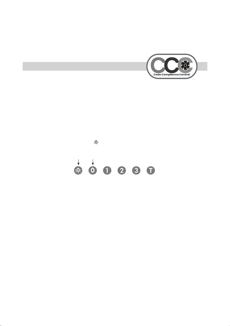
- 65 -
Code Compliance Control
¡Nuevo!
Algunos códigos locales limitan el flujo máximo de aire de escape de las campanas
de rango a 400 CFM antes de que se requiera un sistema de aire de reposición.
Los modelos XOI3015SC y XOI3315SC se suministran con una capacidad de 600 CFM.
El sistema CCC le permite limitar la campana de 600 CFM a 395 CFM.
Para configurar la operación 395 CFM, siga el siguiente procedimiento:
1. Una vez que la campana se haya encendido inicialmente, desconecte la fuente de
alimentación apagando el disyuntor.
2. MUY IMPORTANTE, después de volver a encender la unidad, debe presionar y
mantener pulsados los botones y “0” simultáneamente dentro de los 5 segundos
posteriores a volver a encender la unidad.
NOTA: Si no pulsa los botones dentro de los primeros 5 segundos después de volver
a encender la campana, la función CCC no se activará y debe repetir el paso 1.
3. El control parpadea 3 veces
4. La campana ahora está configurada en 395 CFM - la función de AUMENTO DE
POTENCIA también está deshabilitada.
5. Fije la pegatina suministrada para indicar que la unidad ha sido reconfigurada a un
flujo de aire máximo de 395 CFM.
6. Una vez reconfigurada para 395 CFM, la unidad no se puede restablecer a
600 CFM.
reconversión de aire

- 66 -
KITS DE RECIRCULACIÓN
FILTROS
LUCES DE REPUESTO
MANDOS A DISTANCIA
CUBIERTAS DE CONDUCTOS
INTERRUPTORES DE REPUESTO
MOTORES DEL SOPLADOR
RUEDAS DEL VENTILADOR
TODAS ESTAS PIEZAS Y MÁS ESTÁN DISPONIBLES,
SIMPLEMENTE VISITE WWW.XOAPPLIANCE.COM y haga clic
en LA TIENDA de piezas O LLÁMENOS al 973-403-8900
piezas de acceso y accesorios

- 67 -
YEAR
WARRANTY
2
PARTS + LABOR
A los 90 DÍAS ÁMALO o DÉJALO. Durante 90 días, todos nuestros productos están respaldados por nuestra garantía única
Ámalo o Déjalo.
PIEZAS DE DOS AÑOS Y GARANTÍA LIMITADA DE MANO DE OBRA. XO garantiza al comprador original de cada nueva
unidad de ventilación XO, el gabinete y todas sus partes, estar libre de defectos de material o mano de obra bajo uso y man-
tenimiento normal y adecuado según lo especificado por XO y tras la instalación y puesta en marcha adecuadas de acuerdo
con el paquete de instrucciones suministrado con cada unidad XO. La obligación de XO en virtud de esta garantía se limita a
un período de dos (2) años a partir de la fecha de compra original.
RECLAMACIONES DE GARANTÍA. Todas las reclamaciones de mano de obra o piezas deben hacerse directamente a través
de XO. Todas las reclamaciones deben incluir: número de modelo y número de serie del gabinete, comprobante de compra
y fecha de instalación. En caso de compresor garantizado, la etiqueta del modelo del compresor debe devolverse a XO junto
con la información mencionada anteriormente.
LO QUE NO ESTÁ CUBIERTO POR ESTA GARANTÍA. La única obligación de XO en virtud de esta garantía
se limita a la reparación o reemplazo de piezas, sujeto a las limitaciones adicionales a continuación. Esta garantía no asume
ni autoriza a ninguna persona a asumir obligaciones distintas de las expresamente cubiertas por esta garantía. Las cajas
abiertas, los segundos de fábrica, los arañazos y abolladuras, los modelos de suelo y las aplicaciones comerciales están
excluidos de estas garantías.
LA GARANTÍA NO ES TRANSFERIBLE. Esta garantía no es asignable y solo se aplica a favor del comprador/usuario ori-
ginal en el lugar de instalación original. Cualquier cesión o transferencia anulará las garantías aquí hechas y anulará todas
las garantías, expresas o implícitas, incluyendo cualquier garantía o comerciabilidad o idoneidad para un propósito particular.
USO INADECUADO. XO no asume ninguna responsabilidad por las piezas o la cobertura de mano de obra por fallas en
los componentes u otros daños resultantes del uso o la instalación inadecuados o la falta de limpieza y/o mantenimiento del
producto como se establece en el paquete de garantía proporcionado con la unidad.
ALTERACIÓN O NEGLIGENCIA. XO no es responsable de la reparación o reemplazo de cualquier pieza que XO determine que ha sido
sometida después de la fecha de fabricación a alteración, negligencia, abuso, mal uso, accidente, daño durante el tránsito o
la instalación, incendio, o cualquier evento o accidente no influenciado por el hombre.
CONEXIONES ELÉCTRICAS INADECUADAS. XO no es responsable de la reparación o reemplazo de compo-
nentes defectuosos o dañados como resultado de fallas de energía eléctrica, alta o baja tensión, uso de cables de extensión
o conexión a tierra inadecuada de la unidad.
SUS DERECHOS BAJO LA LEY ESTATAL. Esta garantía le otorga derechos legales específicos y es posible
que tenga otros derechos que varían de un estado a otro. Algunos estados no permiten la exclusión o limitación de daños
consecuentes o una limitación en el tiempo que dura una garantía implícita, por lo que la exclusión o limitación anterior puede
no aplicarse a usted.
FUERA DE LOS EE.UU Esta garantía no se aplica, y XO no se hacer responsable de, ninguna reclamación de garantía
hecha en productos vendidos o usados fuera de los 48 Estados Unidos continentales.
Para obtener el servicio:
Llame al 973-403-8900 |envíe un correo electrónico a ser[email protected]
| o envíe una solicitud a nuestro sitio web
te cubrimos la espalda

3011000129500.00
