Warning notices: Before using this product,
please read this manual carefully and keep
it for future reference.
change without prior notice for product
improvement. Consult with your dealer or
the manufacturer for details.
Download the app
& activate product
USER MANUAL
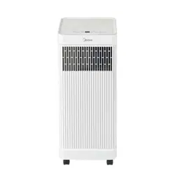
Portable
Air Conditioner
MPX0812CWRU
MPX1011CWRU

Page 2 User Manual
Read This Manual
Inside you’ll nd many helpful hints on how to use and maintain your air conditioner properly.
Just a little preventive care on your part can save you a great deal of time and money
over the life of your air conditioner. You’ll nd many answers to common problems in the
troubleshooting tips - you should be able to x most of them quickly before calling service.
These instructions may not cover every possible condition of use, so common sense and
attention to safety is required when installing, operating and maintaining this product.
• For support, please call the Service Center at 1-855-204-5313.
• This appliance is not intended for use by persons (including children) with reduced physical,
sensory or mental capabilities or lack of experience and knowledge, unless they have been
given supervision or instruction concerning use of the appliance by a person responsible for
their safety.
• Children should be supervised to ensure that they do not play with the air conditioner.
• The appliance shall be installed in accordance with national wiring regulations.
• Do not operate your air conditioner in a humid room such as a bathroom or laundry room.
CAUTION
Safety Precautions .................................................................................................................... 3
Before You Get Started ..........................................................................................................13
Installation Instructions ........................................................................................................ 15
Operating Instructions .......................................................................................................... 23
Cleaning & Maintenance ..................................................................................................... 26
Troubleshooting Tips ............................................................................................................. 28
Remote Control and App Instructions ............................................................................ 29
CONTENTS
Warranty ...................................................................................................................................... 47
Electronic Work
User Manual
Page 3
Must read the warning message.
Read Safety Precautions Before Operation and Installation
To prevent death or injury to the user or other people and property damage, the
following instructions must be followed.
Incorrect operation due to ignoring of instructions may cause death, harm or damage.
Explanation of Symbols
CAUTION
This symbol indicates the possibility of property damage or serious
consequences.
WARNING
This symbol indicates the possibility of person
l injury or loss of life.
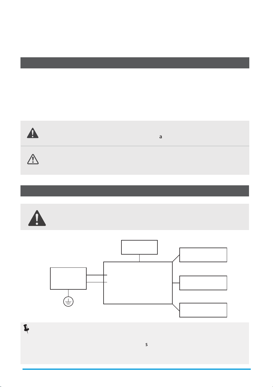
WARNING:
BEFORE PERFORMING ANY ELECTRICAL OR WIRING WORK, TURN OFF THE
MAIN POWER TO THE SYSTEM.
Main Control
Compressor
Fan Motor
Display
Power
Supply
L/AC L/L1/L-IN
N/AC N/L2/N-IN
Other
Electronic Type
NOTICE:
Please strictly follow the wiring label attached to the machine for all wiring connections.
The wiring diagram may vary for dierent unit
. Please refer to the wiring diagram on
the machine you have purchased. The above wiring diagram is a simplied version for
preliminary illustration purposes only.
SAFETY PRECAUTIONS
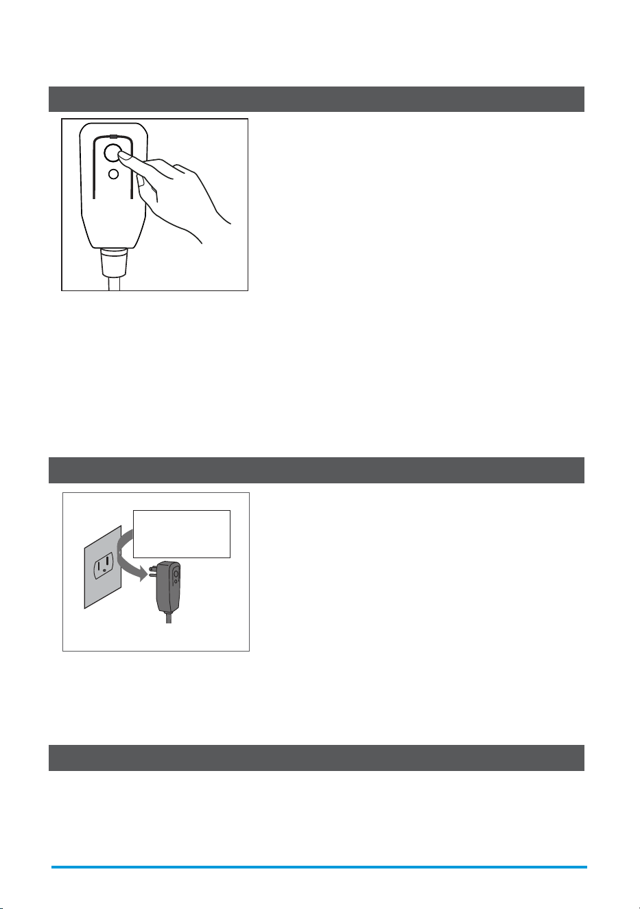
The power supply cord contains a measurement current device that senses damage to the
power cord.
Test your power supply cord as follows:
1. Plug in the air conditioner.
2. The power supply cord will have TWO buttons on the plug head. Press the TEST button.
You will notice a click as the RESET button pops out.
3. Press the RESET Button. You will notice a click as the button engages.
4. The power supply cord is now supplying electricity to the unit. (On some products this
is also indicated by a light on the plug head.)
The power supply cord with this air conditioner contains a current detection device
designed to reduce the risk of re.
In the event that the power supply cord is damaged, it can not be repaired. It must be
replaced with a cord from the manufacturer.
• Do not use this device to turn the unit on or o.
• Always make sure the RESET button is pushed in for correct operation.
• The power supply must be replaced if it fails to reset when either the TEST button is
pushed or it can not be reset. Please contact Customer Service.
Operation of Current Device
NOTICE
NOTICE
Grounding type wall receptacle
Do not, under any
circumstances, cut,
remove or bypass
the grounding prong.
Power supply cord with 3-prong grounding
plug and current detection device.
RESET
TEST
Plug in &
press RESET
User Manual
Page 4
• Installation must be performed according to the installation instructions. Improper
installation can cause water leakage, electrical shock, or re.
• Use only the included accessories and parts, and specied tools for the installation.
Using nonstandard parts can cause water leakage, electrical shock, re, and injury or
property damage.
• Make sure that the outlet you are using is grounded and has the appropriate voltage. The
power cord is equipped with a three-prong grounding plug to protect against shock.
Voltage information can be found on the nameplate of the unit.
• Your unit must be used in a properly grounded wall receptacle. If the wall receptacle you
intend to use is not adequately grounded or protected by a time delay fuse or circuit
breaker (the fuse or circuit breaker needed is determined by the maximum current of the
unit. The maximum current is indicated on the nameplate located on unit), have a qualied
electrician install the proper receptacle.
• Do not touch the unit with wet or damp hands or when barefoot.
• If the air conditioner is knocked over during use, turn o the unit and unplug it from the
main power supply immediately. Visually inspect the unit to ensure there is no damage. If
you suspect the unit has been damaged, contact a technician or customer service for
assistance.
• In a thunderstorm, the power must be cut o to avoid damage to the machine due to
lightning.
• Your air conditioner should be used in such a way that it is protected from moisture. e.g.
condensation, splashed water, etc. Do not place or store your air conditioner where it can
fall or be pulled into water or any other liquid. Unplug immediately if it occurs.
• Install the unit on a at, sturdy surface. Failure to do so could result in damage or excessive
noise and vibration.
• The unit must be kept free from obstruction to ensure proper function and to mitigate
safety hazards.
• Do not modify the length of the power cord or use an extension cord to power the unit.
• Do not share a single outlet with other electrical appliances. Improper power supply can
cause re or electrical shock.
• Do not install your air conditioner in a wet room such as a bathroom or laundry room. Too
much exposure to water can cause electrical components to short circuit.
• Do not install the unit in a location that may be exposed to combustible gas, as this could
cause re.
• The unit has wheels to facilitate moving. Make sure not to use the wheels on thick carpet or
to roll over objects, as th
could cause tipping.
• Do not operate a unit that it has been dropped or damaged.
• The appliance with electric heater shall have at least 1 meter of space from
combustible materials.
• All wiring must be performed strictly in accordance with the wiring diagram located inside
of the unit.
• The unit's circuit board(PCB) is designed with a fuse to provide overcurrent protection. The
specications of the fuse are printed on the circuit board, such as: T 3.15A/250V, etc.
• When the water drainage function is not in use, keep the upper and the lower drain plug
rmly
to the unit to get rid of choking. When the drain plug is not in use, it
carefully to prevent children from choking.
WARNING
User Manual
Page 5

User Manual
Page 6
• This appliance is not intended for use by persons (including children) with reduced physical,
sensory or mental capabilities or lack of experience and knowledge, unless they have been
given supervision or instruction concerning use of the appliance by a person responsible for
their safety. Children should be supervised to ensure that they do not play with the
appliance. Children must be supervised around the unit at all times.
• If the supply cord is damaged, it must be replaced by the manufacturer, its service agent or
similarly qualied persons in order to avoid a hazard.
• Do not use this product for functions other than those described in this instruction manual.
• Before cleaning, turn o the power and unplug the unit.
• Disconnect the power if strange sounds, smell
, or smoke comes from it.
• Do not press the buttons on the control panel with anything other than your ngers.
• Do not remove any xed covers. Never use this appliance if it is not working properly, or if it
has been dropped or damaged.
• Do not operate or stop the unit by inserting or pulling out the power cord plug.
• Do not use hazardous chemicals to clean or come into contact with the unit. Do not use the
unit in the presence of inammable substances or vapour such as alcohol, insecticides,
petrol, etc.
• Prior to cleaning or other maintenance, the appliance must be disconnected from the
supply mains.
• Do not remove any xed covers. Never use this appliance if it is not working properly, or if it
has been dropped or damaged.
• Do not run cord under carpeting. Do not cover cord with throw rugs, runners, or similar
coverings. Do not route cord under furniture or appliances. Arrange cord away from trac
area and where it will not be tripped over.
• Do not operate unit with a damaged cord, plug, power fuse or circuit breaker. Discard unit
or return to an authorized service facility for examination and/or repair.
• To reduce the risk of re or electric shock, do not use this fan with any solid-state speed
control device.
• The appliance shall be installed in accordance with national wiring regulations.
• Contact
authorized service technician for repair or maintenance of this unit.
• Do not cover or obstruct the inlet or outlet grilles.
• Always transport your air conditioner in a vertical position and stand on a stable, level
surface during use.
• Always contact a qualied person to carry out repairs. If the damaged power supply cord
must be replaced with a new power supply cord obtained from the product manufacturer
and not repaired.
• Hold the plug by the head of the power plug when taking it out.
• Turn o the product when not in use.
CAUTION
• Servicing shall only be performed as recommended by the equipment manufacturer.
Maintenance and repair requiring the assistance of other skilled personnel shall be carried
out under the supervision of the person competent in the use of ammable refrigerants.
• DO NOT modify the length of the power cord or use an extension cord to power the unit.
• DO NOT share a single outlet with other electrical appliances. Improper power supply can
cause re or electrical shock.
• Please follow the instruction
carefully to handle, install, clear, service the appliance to
avoid any damage or hazard.
Flammable Refrigerant R32 is used within appliance.
• When maintaining or disposing the appliance, the refrigerant (R32) shall be recovered
properly, shall not discharge to air directly.
• Compliance with national gas regulations shall be observed.
• Keep ventilation openings clear of obstruction.
• The appliance shall be stored so as to prevent mechanical damage from occurring.
•
he appliance shall be stored in a well-ventilated area where the room size corresponds
to the room area as specied for operation.
• Any person who is involved with working on or breaking into a refrigerant circuit should
hold a current valid certicate from an industry-accredited assessment authority, which
authorises their competence to handle refrigerants safely in accordance with an industry
recognised assessment specication. All training shall follow the ANNEX HH requirements
of UL 60335-2-40 4th Edition.
Examples for such working procedures are:
• breaking into the refrigerating circuit;
• opening of sealed components;
• opening of ventilated enclosures.
WARNING:
User Manual
Page 7
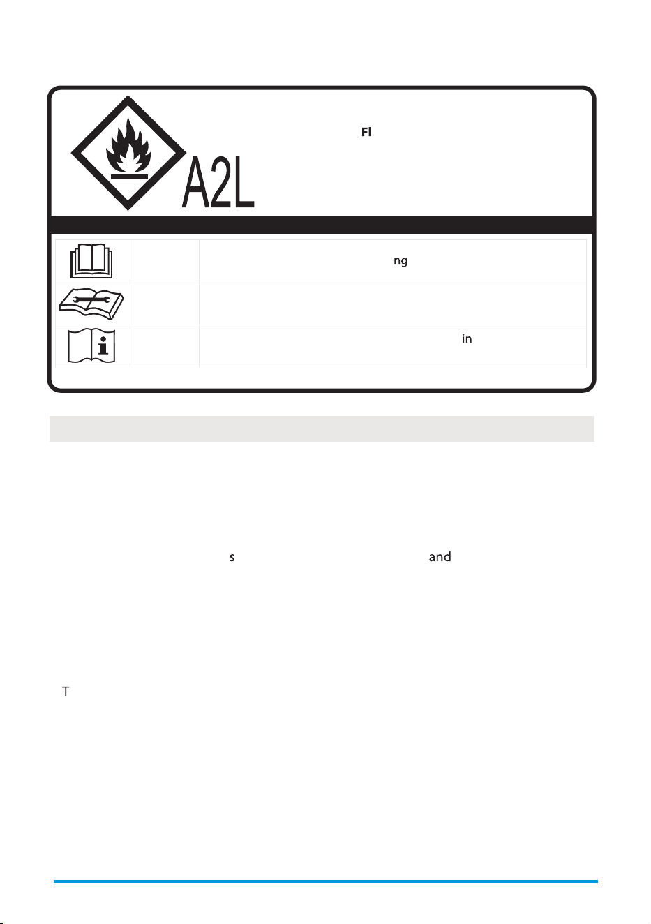
Explanation of symbols displayed on the unit
CAUTION
This symbol shows that the operati manual should be read carefully.
CAUTION
This symbol shows that a service personnel should be handling this
equipment with reference to the installation manual.
CAUTION
This symbol shows that information is available the operating
manual or installation manual.
CAUTION:
Risk of re
ammable materials
IMPORTANT NOTE:
Read this manual
carefully before installing or operating
your new appliance unit.
Make sure to save this manual for future
reference.
4) Checking for presence of refrigerant
The area shall be checked with an appropriate refrigerating detector prior to and during
i.e. non-sparking, adequately sealed or intrinsically safe.
1) Checks to the area
necessary to ensure that the risk of ignition is minimised. For repair to the refrigerating
system, the following precautions shall be complied with prior to conducting work on the
system.
2) Work procedure
Work shall be undertaken under a controlled procedure so as to minimise the risk of a
3) General work area
Transport of equipment containing ammable refrigerants
See transport regulations.
Marking of equipment using signs
See local regulations.
Disposal of equipment using ammable refrigerants
See national regulations.
Storage of equipment/appliances
The storage of the appliance should be in accordance with the applicable regulations or
instructions, whichever is more stringent.
Storage of packed (unsold) equipment
Storage package protection should be constructed such that mechanical damage to the
equipment inside the package will not cause a leak of the refrigerant charge. The
maximum number of pieces of equipment permitted to be stored together will be
determined by local regulations.
Information on servicing
• No open re or device like switch which may generate spark/arcing shall be
round
appliance to avoid causing ignition of the ammable refrigerant used.
Please follow the instruction
carefully to store or maintain the appliance to prevent
mechanical damage from occurring.
• Do not use means to accelerate the defrosting process or to clean, other than those
recommended by the manufacturer.
• The appliance shall be stored in a room without continuously operating ignition sources
(for example: open ames, an operating gas appliance) and ignition sources or (for
example: an operating electric heater) close to the appliance.
• Do not pierce or burn.
• Be aware that the refrigerants may not contain an odour.
User Manual
Page 8

Presence of re extinguisher
If any hot work is to be conducted on the refrigeration equipment or any associated parts,
appropriate re extinguishing equipment shall be available to hand. Have a dry powder or
CO2 re extinguisher adjacent to the charging area.
No ignition sources
No person carrying out work in relation to a refrigerating system which involves exposing
any pipe work that contains or has contained ammable refrigerant shall use any sources
of ignition in such a manner that it may lead to the risk of re or explosion. All possible
ignition sources, including cigarette smoking, should be kept suciently far away from
the site of installation, repairing, removing and disposal, during which ammable
refrigerant can possibly be released to the surrounding space. Prior to work taking place,
the area around the equipment is to be surveyed to make sure that there are no
ammable hazards or ignition risks. No Smoking signs shall be displayed.
entilated area
Ensure that the area is in the open or that it is adequately ventilated before breaking into
the system or conducting any hot work. A degree of ventilation shall continue during the
period that the work is carried out. The ventilation should safely disperse any released
refrigerant and preferably expel it externally into the atmosphere.
Checks to the refrigerating equipment
Where electrical components are being changed, they shall be t for the purpose and to
the correct specications. At all times
the manufacturer's maintenance and service
guidelines shall be followed. If in doubt
consult the manufacturer's technical department
for assistance. The following checks shall be applied to installations using ammable
refrigerants: the actual refrigerant charge is in accordance with the room size within which
the refrigerant containing parts are installed; the ventilation machinery and outlets are
operating adequately and are not obstructed; if an indirect refrigerating circuit is being
used, the secondary circuit shall be checked for the presence of refrigerant; marking to the
equipment continues to be visible and legible.
Markings and signs that are illegible shall be corrected; and refrigerating pipe or
components are installed in a position where they are unlikely to be exposed to any
substance which may corrode refrigerant containing components, unless the components
are constructed of materials which are inherently resistant to being corroded or are
suitably protected against being so corroded.
Checks to electrical devices
Repair and maintenance to electrical components shall include initial safety checks and
component inspection procedures. If a fault exists that could compromise safety, then no
electrical supply shall be connected to the circuit until it is satisfactorily dealt with. If the
fault cannot be corrected immediately but it is necessary to continue operation, an
adequate temporary solution shall be used.
This shall be reported to the owner of the equipment so all parties are advised.
Initial safety checks shall include: That capacitors are discharged: this shall be done in a
safe manner to avoid possibility of sparking; that there no live electrical components and
wiring are exposed while charging, recovering or purging the system; that there is
continuity of earth bonding.
User Manual
Page 9
11. Removal and evacuation
When breaking into the refrigerant circuit to make repairs—or for any other purpose -
procedure shall be adhered to:
- Safely remove refrigerant following local and national regulations;
- Evacuate;
- Purge the circuit with inert gas (optional for A2L);
- Evacuate (optional for A2L);
- Open the circuit.
The refrigerant charge shall be recovered into the correct recovery cylinders if venting is
the system shall be purged with oxygen-free nitrogen to render the appliance safe for
Compressed air or oxygen shall not be used for purging refrigerant systems.
down to a vacuum (optional for A2L). This process shall be repeated until no refrigerant is
the system shall be vented down to atmospheric pressure to enable work to take place.
The outlet for the vacuum pump shall not be close to any potential ignition sources, and
ventilation shall be available.
User Manual
Page 10
Under no circumstances shall potential sources of ignition be used in the searching for or
shall not be used.
The following leak detection methods are deemed acceptable for systems containing
refrigerants, but the sensitivity may not be adequate, or may need re-calibration.
(Detection equipment shall be calibrated in a refrigerant-free area.) Ensure that the
detector is not a potential source of ignition and is suitable for the refrigerant used. Leak
detection equipment shall be set at a percentage of the LFL of the refrigerant and shall be
calibrated to the refrigerant employed and the appropriate percentage of gas (25 %
but the use of detergents containing chlorine shall be avoided as the chlorine may react
with the refrigerant and corrode the copper pipe-work. If a leak is suspected, all naked
brazing, all of the refrigerant shall be recovered from the system, or isolated (by means of
be according to Removal and evacuation.
Check that cabling will not be subject to wear, corrosion, excessive pressure, vibration,
fans.
7. Sealed electrical components shall be replaced.
8. Intrinsically safe components must be replaced.
9. Cabling
14. Labelling
Equipment shall be labelled stating that it has been de-commissioned and emptied of
refrigerant. The label shall be dated and signed. Ensure that there are labels on the
User Manual
Page 11
13. Decommissioning
Before carrying out this procedure, it is essential that the technician is completely familiar
with the equipment and all its detail. It is recommended good practice that all refrigerants
are recovered safely. Prior to the task being carried out, an oil and refrigerant sample shall
be taken in case analysis is required prior to re-use of reclaimed refrigerant. It is essential
that electrical power is available before the task is commenced.
a) Become familiar with the equipment and its operation.
b) Isolate system electrically.
c) Before attempting the procedure ensure that: Mechanical handling equipment is
available, if required, for handling refrigerant cylinders;all personal protective
equipment is available and being used correctly; the recovery process is supervised at
all times by a competent person; recovery equipment and cylinders conform to the
appropriate standards.
d) Pump down refrigerant system, if possible.
e) If a vacuum is not possible, make a manifold so that refrigerant can be removed from
various parts of the system.
f) Make sure that cylinder is situated on the scales before recovery takes place.
g) Start the recovery machine and operate in accordance with manufacturer's instructions.
h)
i) Do not exceed the maximum working pressure of the cylinder, even temporarily.
j)
that the cylinders and the equipment are removed from site promptly and all isolation
k) Recovered refrigerant shall not be charged into another refrigeration system unless it
has been cleaned and checked.
12. Charging procedures
In addition to conventional charging procedures, the following requirements shall be
charging equipment. Hoses or lines shall be as short as possible to minimise the amount
of refrigerant contained in them. Cylinders shall be kept in an appropriate position
according to the instructions. Ensure that the refrigeration system is earthed prior to
charging the system with refrigerant. Label the system when charging is complete (if not
recharging the system it shall be pressure tested with OFN. The system shall be leak tested
on completion of charging but prior to commissioning. A follow up leak test shall be
carried out prior to leaving the site.
User Manual
Page 12
15. Recovery
When removing refrigerant from a system, either for servicing or decommissioning, it is
recommended good practice that all refrigerants are removed safely. When transferring
refrigerant into cylinders, ensure that only appropriate refrigerant recovery cylinders are
employed. Ensure that the correct number of cylinders for holding the total system charge
is available. All cylinders to be used are designated for the recovered refrigerant and
labelled for that refrigerant (i.e. special cylinders for the recovery of refrigerant). Cylinders
order. Empty recovery cylinders are evacuated and, if possible, cooled before recovery
occurs. The recovery equipment shall be in good working order with a set of instructions
concerning the equipment that is at hand and shall be suitable for the recovery of the
of calibrated weighing scales shall be available and in good working order. Hoses shall be
complete with leak-free disconnect couplings and in good condition.
The recovered refrigerant shall be processed according to local legislation in the correct
recovery cylinder, and the relevant waste transfer note arranged. Do not mix refrigerants
in recovery units and especially not in cylinders. If compressors or compressor oils are to
be removed, ensure that they have been evacuated to an acceptable level to make certain
When oil is drained from a system, it shall be carried out safely.
Energy Rating Information
The energy rating and noise information for this unit is based on the standard installation using an
un-extended exhaust duct without window slider adapt
r (as shown in the Installation section of this
manual) ith the unit operating on COOL MODE and HIGH FAN SPEED.
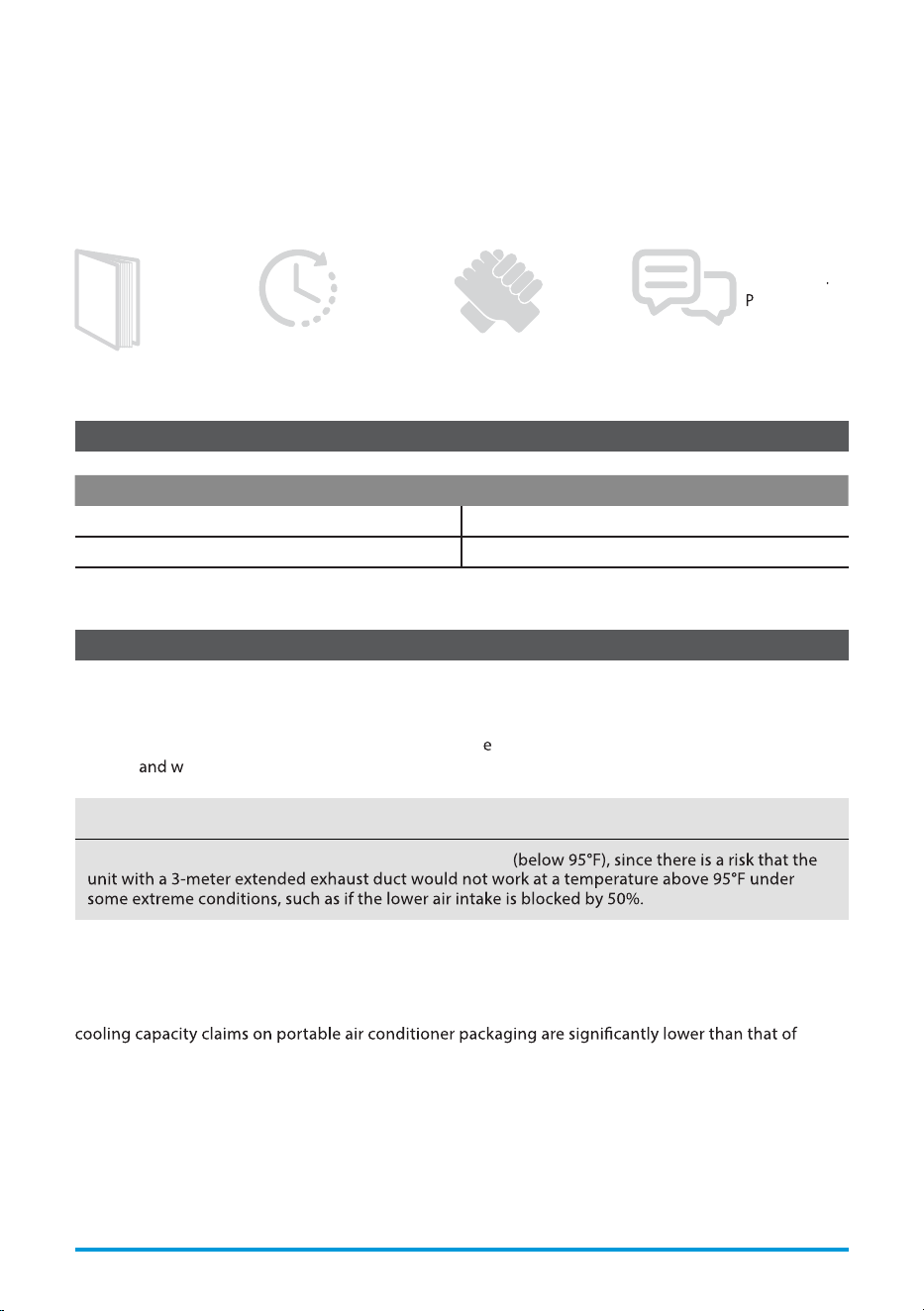
The installation
must be carried
out in strict
accordance with
the instructions
in this manual.
We recommend
doing this with
a helper.
Installing
your AC
should take
about
30 minutes.
We’re here if
you need us
lease contact
1-855-204-5313
Preparations Before Installation
Manual
Mode Temperature Range
Cool 16~35°C (60~95°F)
Dry 13~35°C (55~95°F)
Ambient Temperature Range For Unit Operating:
Know your Portable Air Conditioner
How to Stay Cool with a New Portable Air Conditioner (For the models comply with the
requirements of Department Of Energy in US)
Because of a new federal test procedure for Portable Air Conditioners, you may notice that the
models produced prior to 2017. This is due to changes in the test procedure, not to the portable air
conditioners themselves.
NOTICE
We recommend operating the unit at room temperature
User Manual Page 13
BEFORE YOU GET STARTED
What Should I Look For First When Purchasing A Portable Air Conditioner?
conditioner, determine the square footage of the room you want to cool by multiplying the room length
by its width. You also need to know the air conditioner’s BTU (British Thermal Unit) rating, which indicates
the amount of heat it can remove from a room. A higher number means more cooling power for a larger
room. (Be sure you are comparing only newer models to each other. Older models may appear to have
a higher capacity, but are actually the same). Be sure to “size up” if your portable air conditioner will be
placed in a very sunny room, in a kitchen, or in a room with high ceilings. After you’ve found the right
cooling capacity for your room, you can look at other features.
Why Newer Products Have Lower Cooling Capacity Than Older Models
procedure, which was changed just this year. Models manufactured before 2017 were tested under a
BTUs may be lower now, the actual cooling capacity of the air conditioners has not changed.
What is SACC?
SACC is the representative value of Seasonally Adjusted Cooling Capacity, in Btu/h, as determined in
accordance with the DOE test procedure at title 10 Code of Federal Regulations (CFR) 430, subpart B,
appendix CC and applicable sampling plans.
Page 14 User Manual
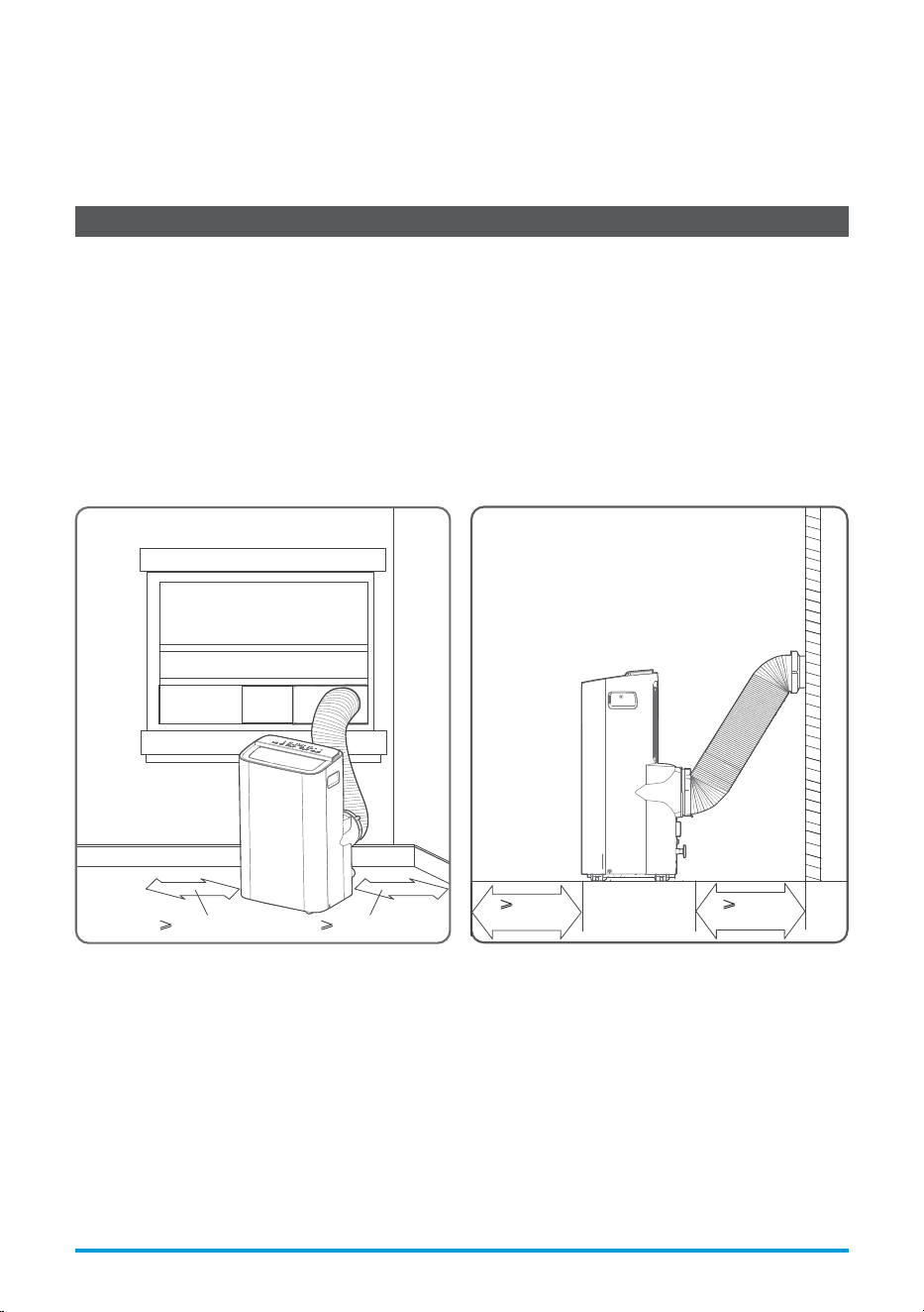
Product Installation Location
Your Installation Location Should Meet The Following Requirements:
• Make sure that you install your unit on an even surface to minimize noise and vibration.
• The unit must be installed near a grounded plug, and the Collection Tray Drain (found on the
back of the unit) must be accessible.
• The unit should be located at least 30cm (12”) from the nearest wall to ensure proper air
conditioning. The air outlet of the unit should be at least 50cm (19.7”) away from obstacles.
• DO NOT cover the Intakes, Outlets or Remote Signal Receptor of the unit, as this could cause
damage to the unit.
Unit Installation Location Restricted Space Requirements
≥30cm (12”)
(19.7”)
≥
50cm
(19.7”)
≥30cm (12”)
≥
50cm
User Manual Page 15
INSTALLATION INSTRUCTIONS
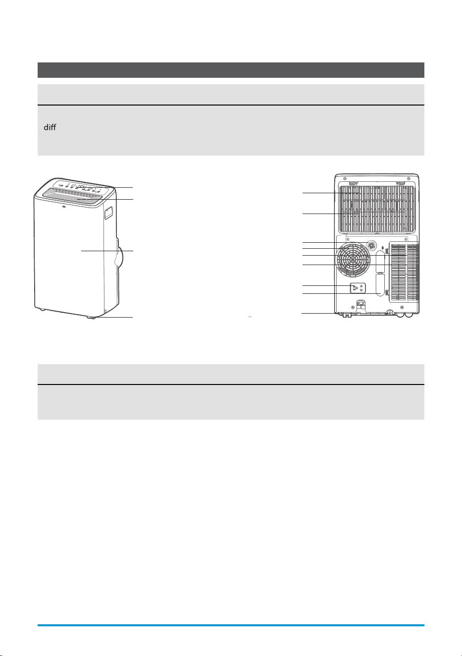
Product Overview
DESIGN NOTICE
In order to ensure optimal performance of our products, the design specications of the unit
and remote control are subject to change without prior notice.
NOTICE
All the illustrations in the manual are for explanation purpose only. Your machine may be slightly
erent. The actual shape shall prevail.
The unit can be controlled by the unit control panel alone or with the remote control.
Page 16 User Manual
Front View
Caster
horizontal louver blade
(swing automatically)
Control panel
Front panel
Rear View
Drain outlet
Power plug socket
Power cord buckle
Bottom tray drain outlet
Upper air filter
(behind the grille)
Upper air intake
Air outlet
Lower air filter
Lower air intake
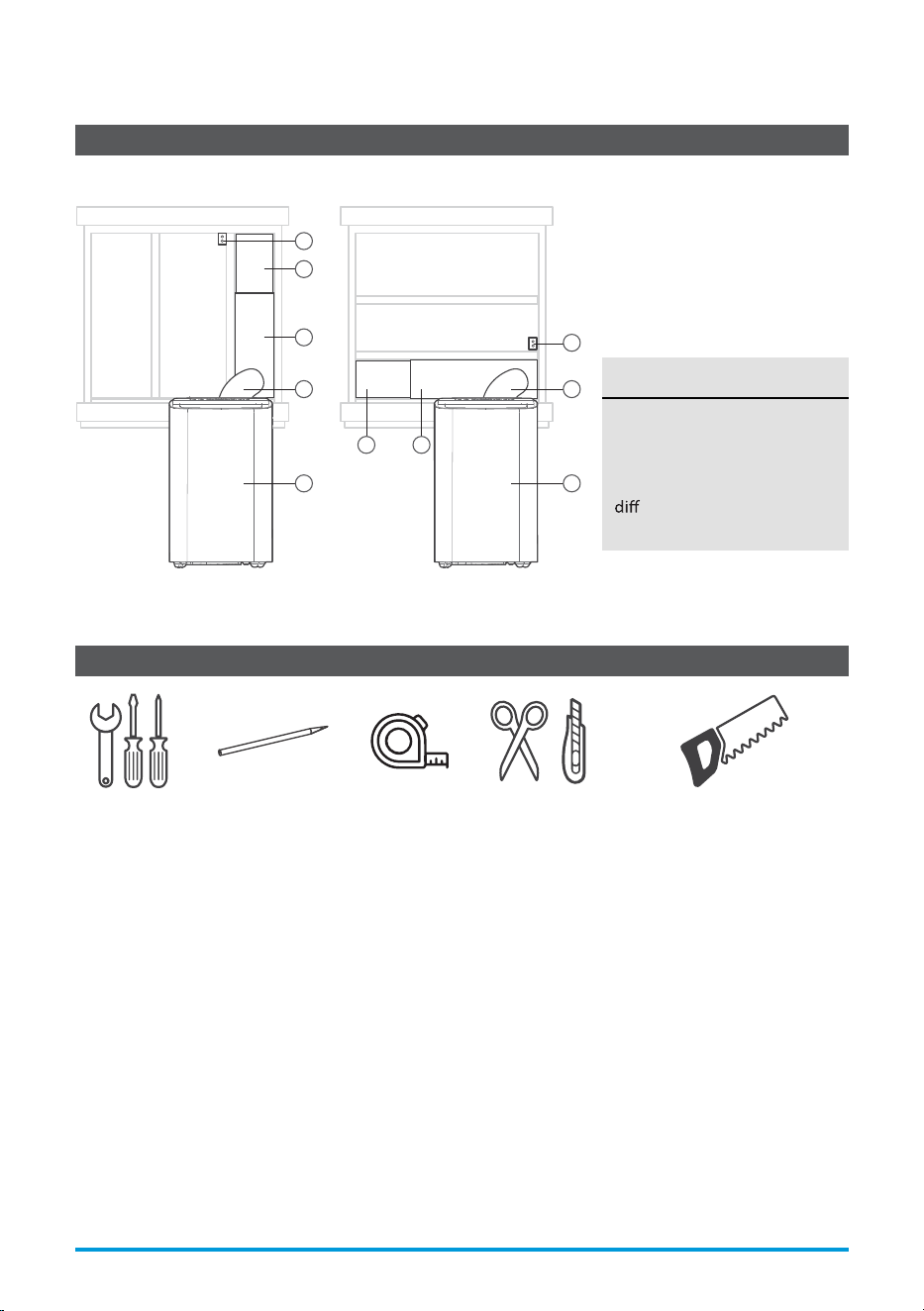
Installation Overview
NOTICE
Illustrations in this manual
are for explanatory purposes.
The actual shape of your
indoor unit may be slightly
erent. The actual shape
shall prevail.
Sliding Window Installation Hung Window Installation
1
5
2
3
3
1 2
5
4
4
1. indow Slider
2. indow Slider
3. Extended Exhaust Hose
4. Portable Air Conditioner
5. Security Bracket and 2 Screws
Installation Completion Display
Tools Needed
Screwdriver
& wrench
A tape
measure
Scissors
or Knife
Pencil Saw (On some models,
to shorten window adaptor
for narrow windows)
User Manual Page 17
W
W
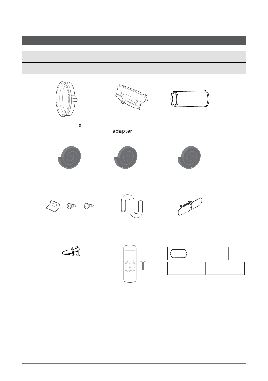
Installation Accessories
NOTICE
Slight variations in design may occur.
Remote Controller
and Battery (only for
remote control models)
(1 set)
Bolt (3 pc)
Security Bracket
and 2 Screws (1 set)
(1 pc)
Exhaust Hose
Drain Hose
(1 pc)
Foam Seal A
(Adhesive) (4 pc)
Foam Seal B
(Adhesive) (2 pc)
Foam Seal C
(Non-adhesive) (2 pc)
Power Cord
Buckle ( 1 pc)
Air exhaust
(1 pc)
(1 pc)
Unit Adapt r
Window Sliders
(1 set)
Page 18 User Manual
For Optimal Performance In Operation
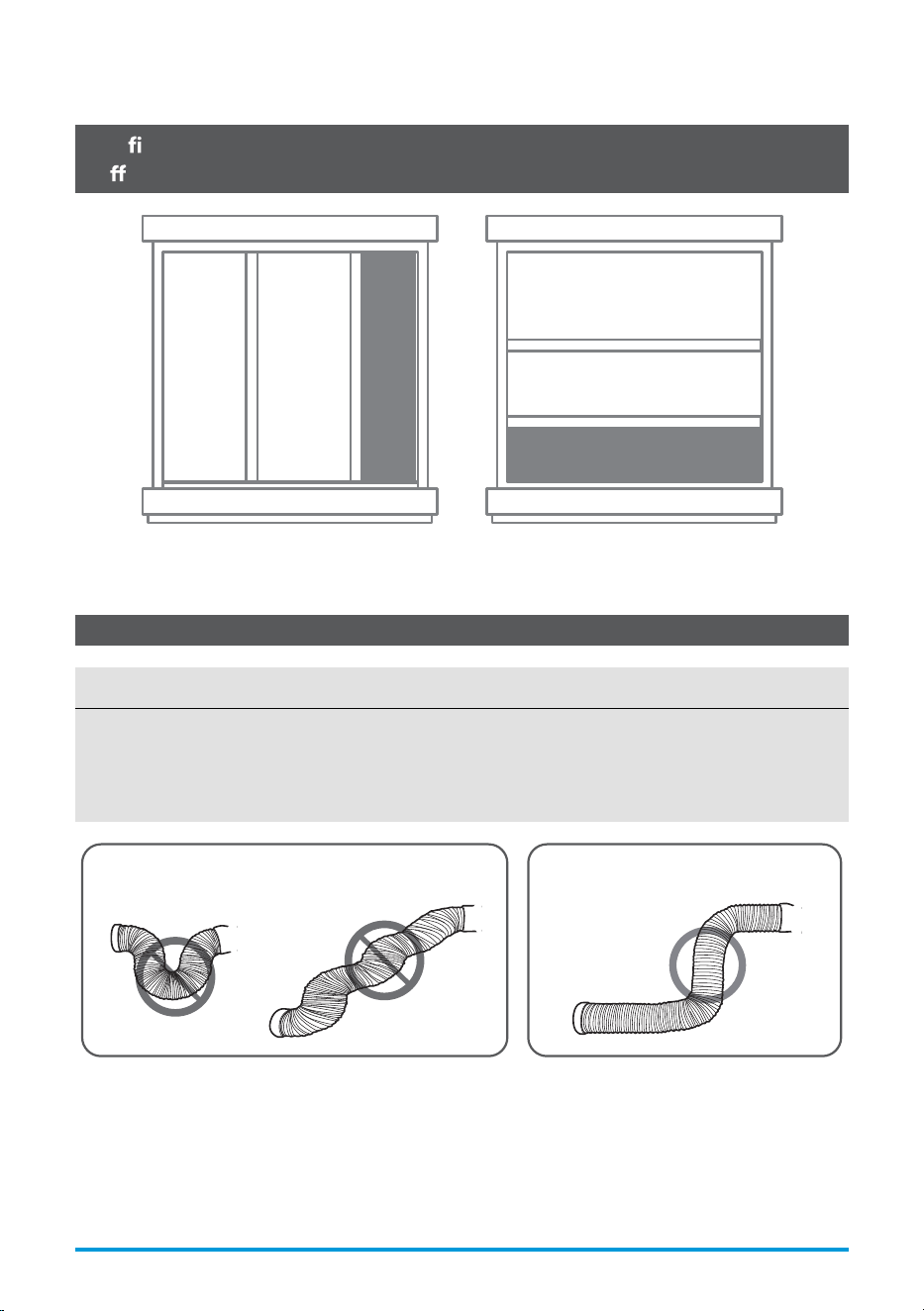
Con rm Your Window Type (Window Type And Opening Size Of
Di erent Types)
Sliding Window Installation Hung Window Installation
NOTICE
To ensure proper function, DO NOT overextend or bend the hose. Make sure that there is no
obstacle around the air outlet of the exhaust hose (in the range of 500mm) in order to ensure the
exhaust system works properly. All the illustrations in this manual are for explanation purpose
only. Your air conditioner may be slightly dierent. The actual shape shall prevail.
INCORRECT CORRECT
User Manual Page 19
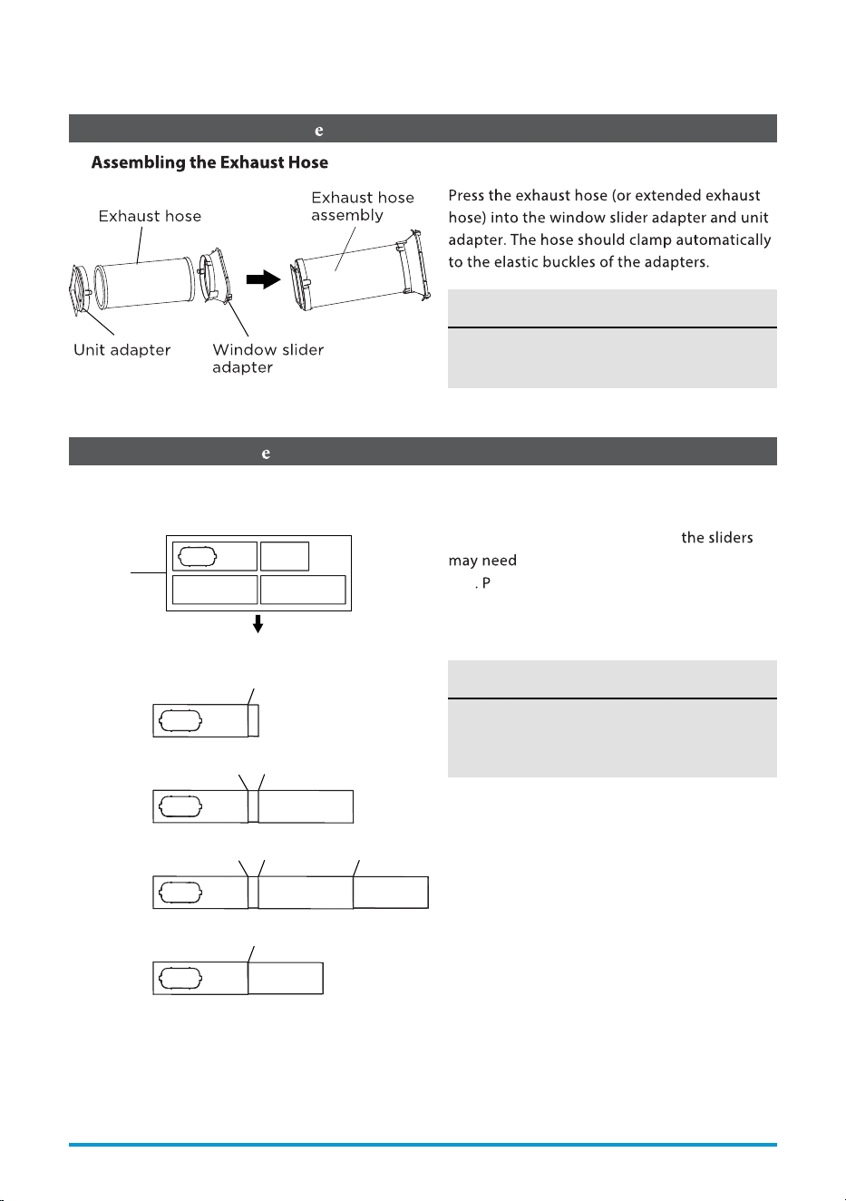
Exhaust Hose And Adapt rs Installation
Connect The Adapt r To The Unit And The Window
1 - :
2 - Preparing the Adjustable Window Slider:
NOTICE
Please install the exhaust hose assembly
according to the ttings in your kit.
Choose the window sliders according to the
size of your window. Sometimes,
to be cut short to meet the window
size
lease take extra care to cut it properly.
Use bolts to fasten the window sliders once
they are adjusted to the proper length.
NOTICE
Please base your window slider installation
on the accessories in your kit and the size
of your window.
1+2 :
Bolt
1+2+3 :
Bolt
Bolt
1+2+3+4 :
BoltBoltBolt
1+4 :
Bolt
Window
Sliders
After assembly
Before assembly
Page 20 User Manual
Foam seal B
(Adhesive type-shorter)
Foam seal A
(Adhesive type)
Foam seal B
(Adhesive type-shorter)
Foam seal A
(Adhesive type)
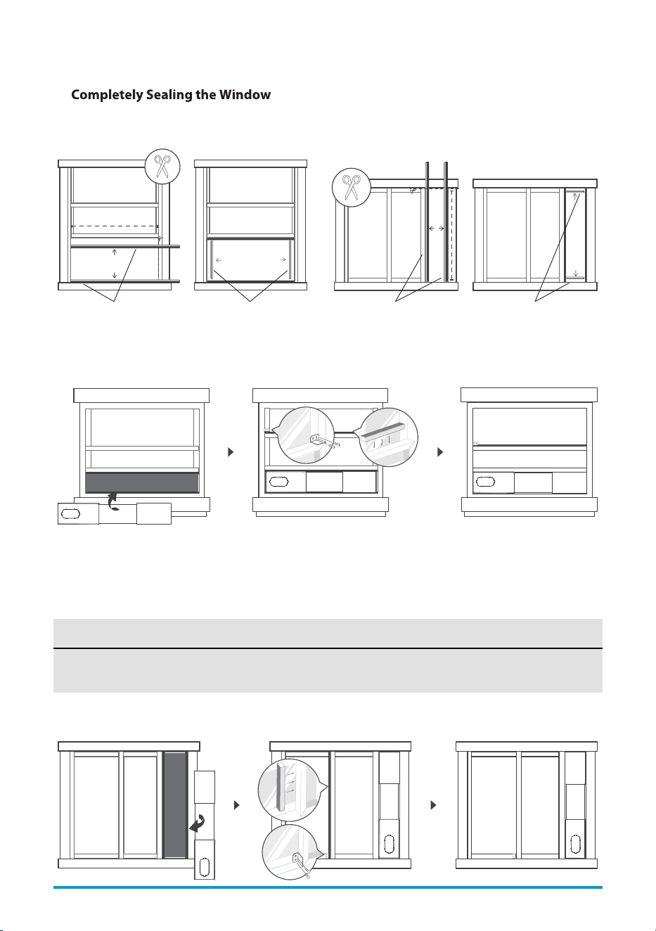
Hung Window Installation Sliding Window Installation
3 - :
Cut the adhesive foam seal A and B strips to the proper lengths, and attach them to the window sash
and frame as shown.
4 - Hung Window Installation:
5 - Sliding Window Installation:
Step 1: Insert the window slider assembly into the window opening.
Step 2: Cut the non-adhesive foam seal C strip to match the width of the window. Insert the seal
between the glass and the window frame to prevent air and insects from getting into the room.
Step 3: If desired, install the security bracket with 2 screws as shown.
NOTICE
Once the exhaust hose assembly and adjustable window slider are prepared, choose one of the
two installation methods based on your window type.
User Manual Page 21
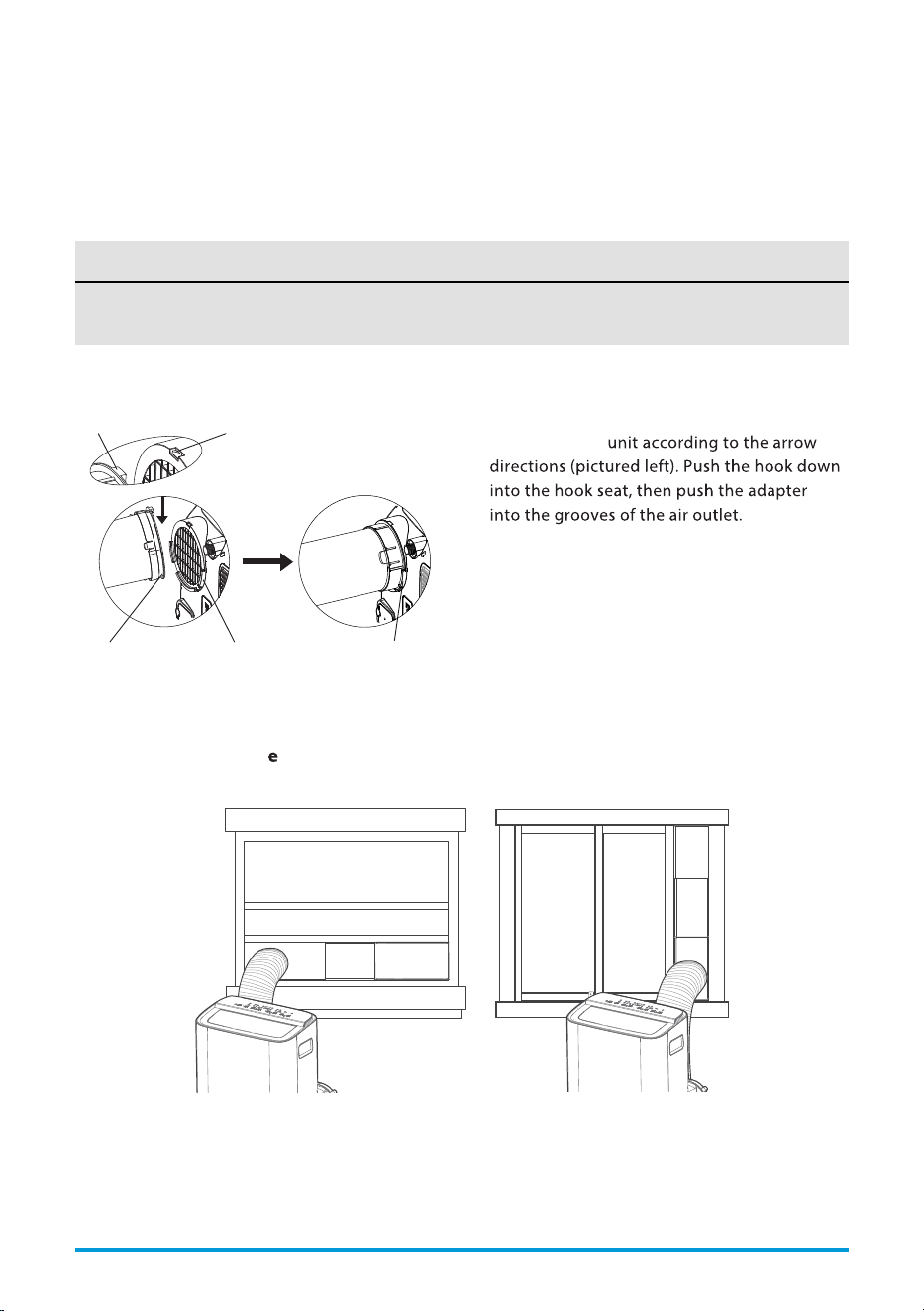
6 - Install The Exhaust Hose Assembly To The Unit:
7 - Connect The Adapt
r To The Unit And The Window:
Insert the window slider adapter into the hole of the window slider.
NOTICE
Once the exhaust hose assembly and adjustable window slider are prepared, choose one of the
two installation methods based on your window type.
Step 1: Insert the window slider assembly into the window opening.
Step 2: Cut the non-adhesive foam seal C strip to match the height of the window. Insert the seal
between the glass and the window frame to prevent air and insects from getting into the room.
Step 3: If desired, install the security bracket with 2 screws as shown.
Push the exhaust hose into the air outlet
opening of the
Hung Window Installation Sliding Window Installation
Hook Hook Seat
Lower
groove
Adapter Make sure the
adapter is inserted
into the lower groove
of the air outlet.
Page 22 User Manual
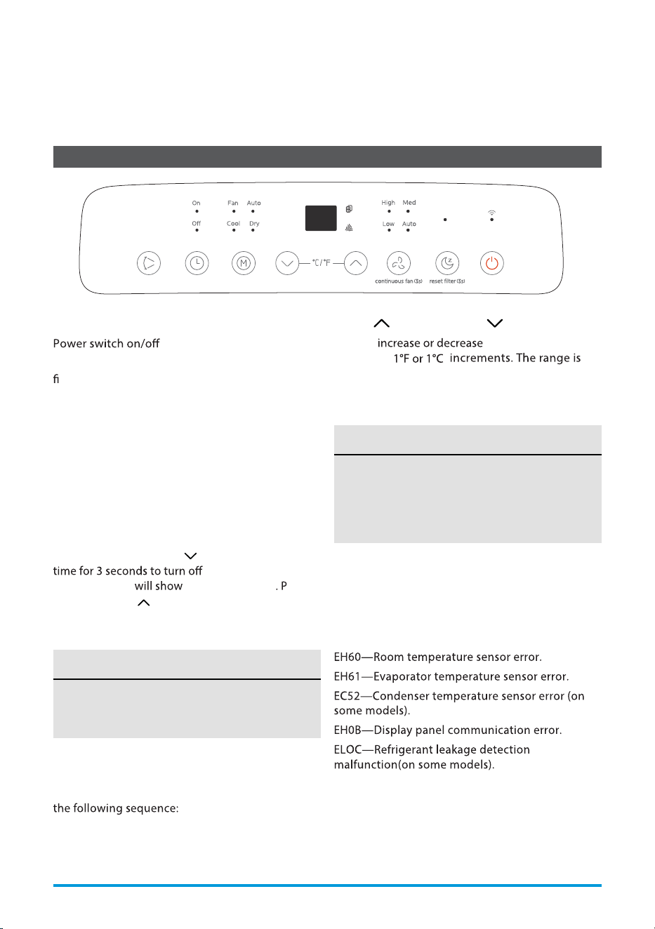
Electronic Control Operating Instructions
1. POWER Button
.
Used to initiate the Wireless function. For the
rst time using the Wireless function, press and
hold the POWER button for 3 seconds to initiate
the Wireless connection mode. The LED DISPLAY
shows ‘AP’ to indicate you can set Wireless
connection. If connection (router) is successful
within 8 minutes, the unit will exit Wireless
connection mode automatically and the Wireless
indicator light illuminates.
If connection fails within 8 minutes, the unit exits
Wireless connection mode automatically. After
Wireless connection is successful, you can press and
hold POWER and DOWN
(
/
-) buttons at the same
wireless function and
the LED display
‘OF’ for 3 seconds ress the
POWER and UP ( /+) buttons at the same time to
turn on Wireless function and the LED DISPLAY
shows ‘On’ for 3 seconds.
When you restart the Wireless function, it
may take a period of time to connect to the
network automatically.
NOTICE
2. MODE Function
Selects the appropriate operating mode. Each
time you press the button, a mode is selected in
AUTO, COOL, DRY, FAN
The mode indicator light illuminates under the
dierent mode settings.
3. UP ( /+) and DOWN ( /-) Buttons
Used to temperature
settings in
16°C/60°F to 30°C/8
F.
TIMER setting in a range of 0~24hrs.
The control is capable of displaying
temperature in degrees Fahrenheit or degrees
Celsius. To convert from one to the other, press
and hold the Up and Down buttons at the
same time for 3 seconds.
NOTICE
4. DISPLAY
Shows the set temperature in °C or °F and the
Auto-timer settings. While on DRY and FAN modes,
it shows the room temperature.
Shows Error codes and protection code:
P1-Bottom tray is full. Connect the drain hose and
drain the collected water. If the P1 code does not
erase, call for service.
User Manual Page 23
OPERATING INSTRUCTIONS
6°
When one of the above malfunctions
occurs, turn o the unit, and check for
any obstructions. Restart the unit, if the
malfunction is still present, turn o the unit
and unplug the power cord.
Contact the manufacturer, its service agents
or a similar q
son for service.
NOTICE
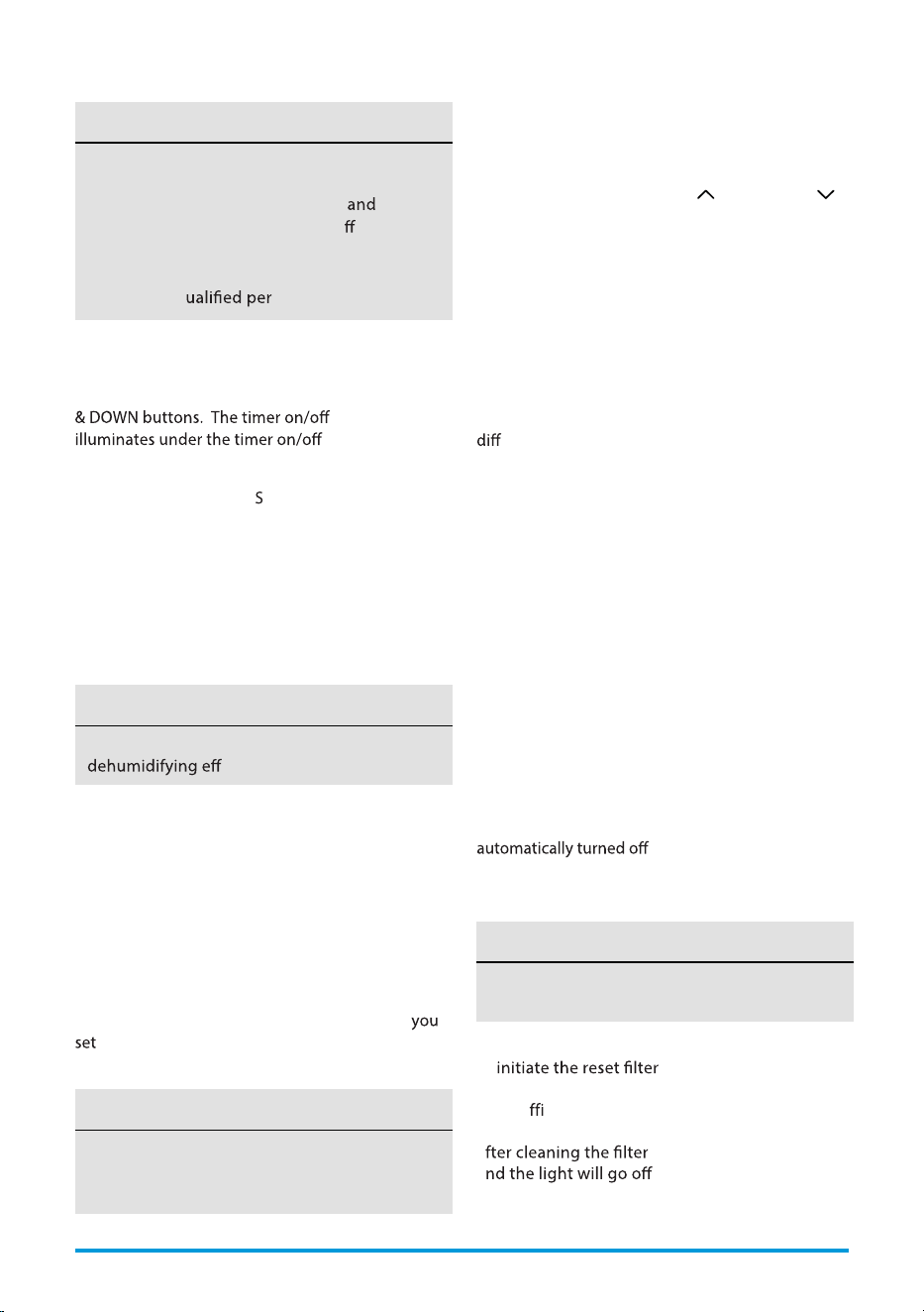
5. TIMER Button
Used to initiate the AUTO ON start time and AUTO
OFF stop time program in conjuction with the UP
indicator light
settings.
Under AUTO mode, both the AUTO mode and
the actual operation mode indicator lights
illuminate for some models.
NOTICE
Keep windows and doors closed for the best
ect.
NOTICE
6. SWING Mode
Used to initiate the Auto
wing feature. When the
operation is ON, press the SWING button to stop
the louver at the desired angle.
7. DRY Mode
To turn on Dry mode, press the “MODE” button until
the “Dry” indicator light comes on. In this mode, the
fan speed or the temperature cannot be adjusted.
8. AUTO Mode
When you set the air conditioner to AUTO mode,
it will automatically select cooling, heating (heat
function only on some models), or fan only
operation depending on what temperature you
have selected and the room temperature. To turn
on Auto mode, press the “MODE” button until the
“Auto” indicator light comes on.
The air conditioner will control room temperature
automatically around the temperature point
. Under AUTO mode, you cannot select the fan
speed.
/+) or DOWN (
/-)
9. COOL Mode
To turn on Cool mode, press the “MODE” button
until the “Cool” indicator light comes on.
Press the ADJUST buttons UP (
This feature is unavailabe under FAN or DRY
mode.
NOTICE
Press and hold on the SLEEP button for 3 seconds
to
connection mode.
This feature is a reminder to clean the Air Filter for
more e
cient operation. The LED (light) will
illuminate after 250 hours of operation. To reset
a
, press the SLEEP button
a
.
to select your desired room temperature.
The temperature can be set within a range of
16°C~30°C/60°F~86°F
Press the “FAN SPEED” button to choose the fan
speed.
10. FAN Mode
To turn on Fan mode, press the “MODE” button until
the “Fan” indicator light comes on.
The fan speed indicator light will illuminate under
erent fan settings.
11. CONSTANT FAN Function
In Cool or Dry mode, press and hold the Fan button
for 3 seconds to turn the constant fan function on or
o. When the function is turned on, the constant fan
light will illuminate. When the function is turned o,
the constant fan light will turn o.
12. SLEEP Mode
Press the sleep button to initiate sleep mode. While
in this mode, the selected temperature will increase
The temperature will then increase or decrease by
This new temperature will be maintained for 7 hours
before it returns to the originally selected
temperature. After the 7 hour period, sleep mode is
and the unit will continue to
operate as originally programmed.
Page 24 User Manual
.
or decrease by 1°C/2°F(or 1°F) after 30 minutes.
another 1°C/2°F(or 1°F) after an additional 30 minutes.
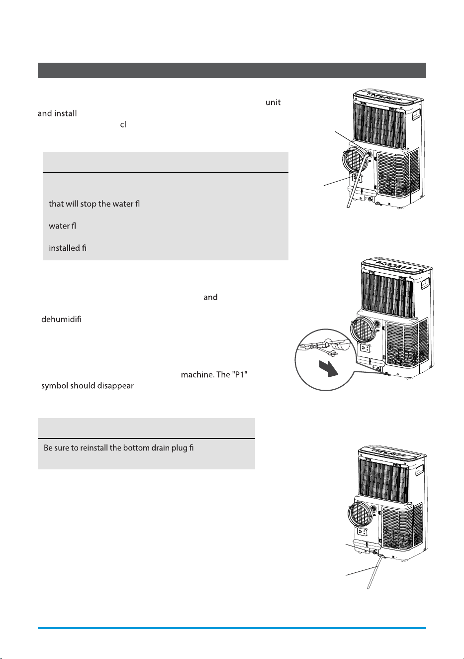
Drainage Guide
rmly to prevent
leakage before using the unit.
NOTICE
During dehumidifying mode or heat pump mode (only on some
models), remove the upper drain plug from the back of the
the drain connector (5/8” universal female mender)
with 3/4” hose (not in uded).
Continuous
drain hose
Remove the
upper drain
plug
When the water level of the bottom tray reaches a
predetermined level, the unit beeps 8 times the digital
display area shows “P1”. At this time the air conditioning/
cation process will immediately stop. However,
the fan motor will continue to operate (this is normal).
Carefully move the unit to a drain location, remove the
bottom drain plug and let the water drain away. Reinstall
the bottom drain plug and restart the
. If the error repeats, call for
service.
Continuous
drain hose
Remove the
lower drain
plug
Make sure the hose is secure so there are no leaks. Direct the
hose toward the drain, making sure that there are no kinks
owing. Place the end of the hose into
the drain and make sure the end of the hose is down to let the
ow smoothly. When the continuous drain hose is not
used, ensure that the corresponding drain plug and knob are
rmly to prevent leakage.
NOTICE
User Manual Page 25
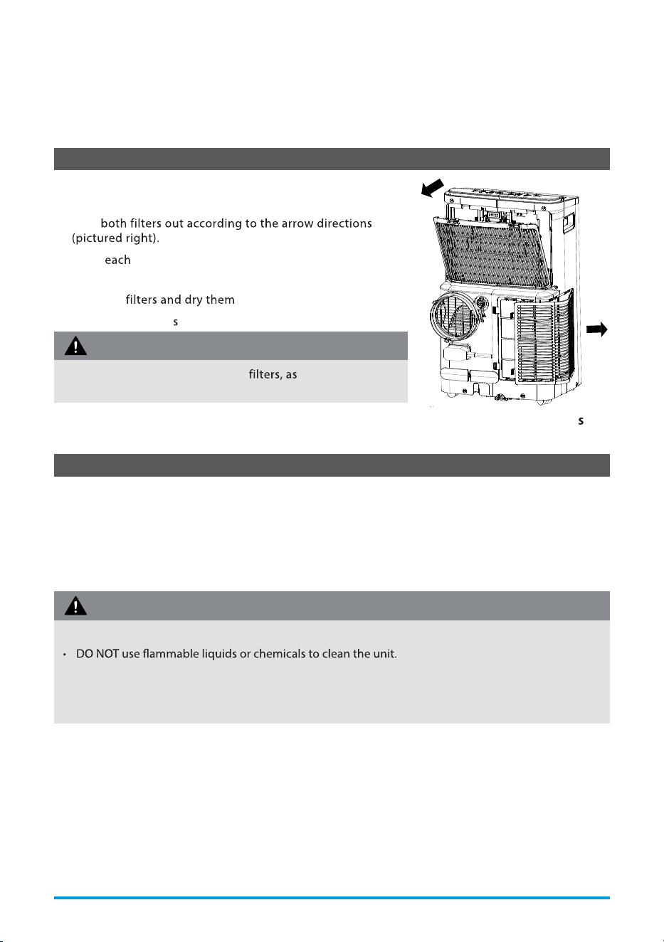
Air Filter & Cabinet Cleaning
Maintenance Tips
Clean the unit using a damp, lint-free cloth and mild detergent.
Dry the unit with a dry, lint-free cloth.
• Take
• Wash air lter by immersing it gently in warm
water (about 40°C/104°F) with a neutral detergent.
• Rinse the in a shady place.
• Install the air lter after cleaning.
• Be sure to clean the air lter every 2 weeks for optimal performance.
• The water collection tray should be drained immediately after P1 error occurs and before
storage to prevent mold.
• In households with animals, you will have to periodically wipe down the grill to prevent blocked
airow due to animal hair.
DO NOT operate the unit without dirt and lint will
clog it and reduce performance.
CAUTION
Remove the air lter
• Always unplug the unit before cleaning or servicing.
• DO NOT wash the unit under running water. Doing so causes electrical danger.
• DO NOT operate the machine if the power supply was damaged during cleaning. A damaged power
cord must be replaced with a new cord from the manufacturer.
CAUTION
Page 26 User Manual
CLEANING & MAINTENANCE
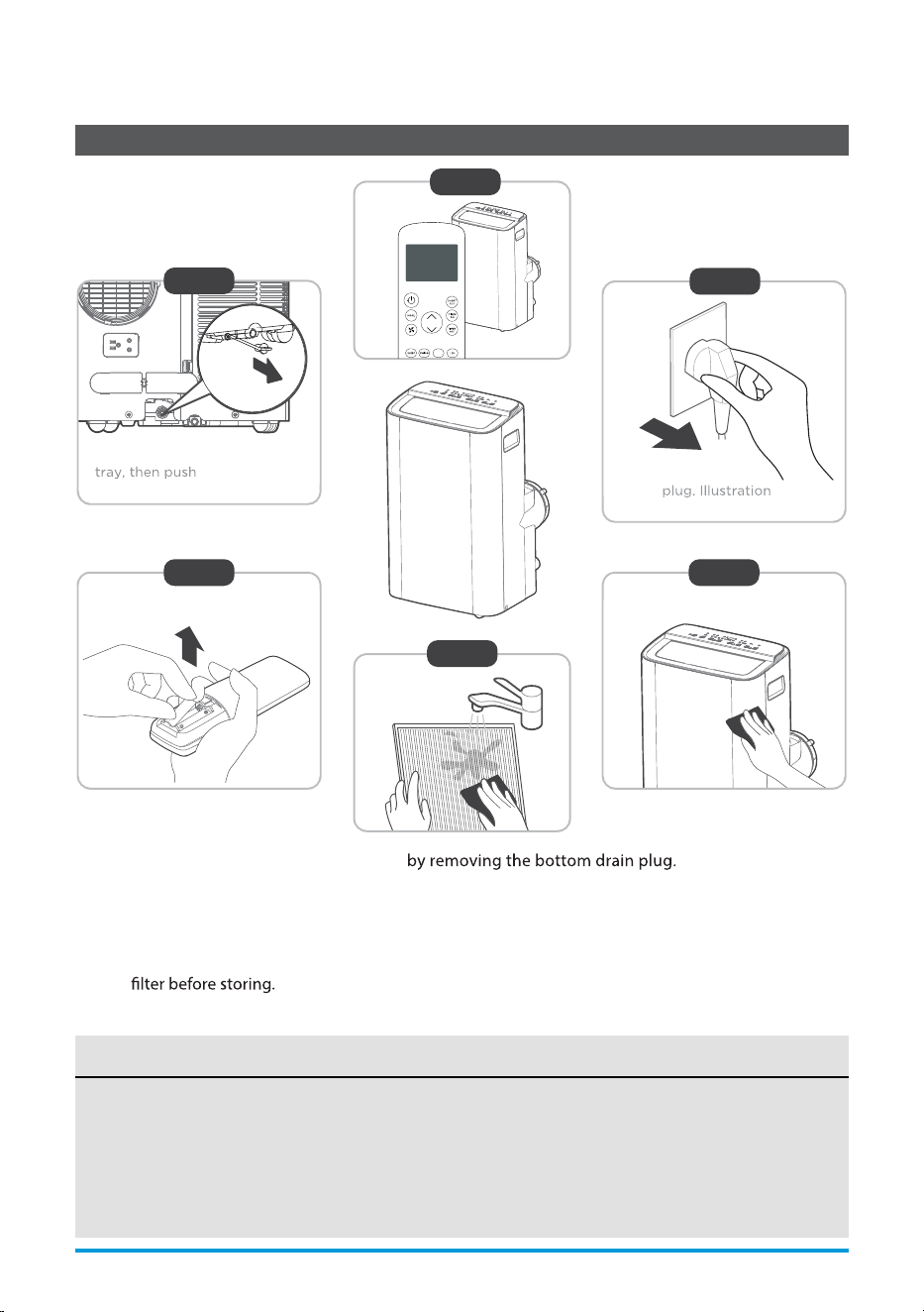
Store The Unit When Not In Use
Step 1: Drain the unit’s water collection tray
Step 2: Run the appliance on FAN mode for 12 hours in a warm room to dry it and prevent mold.
Step 3: Turn o the appliance and unplug it.
Step 4: Clean the machine.
Step 5: Clean the air lter according to the instructions in the previous section. Reinstall the clean, dry
Step 6: Remove the batteries from the remote control.
NOTICE
• Be sure to store the unit in a cool, dark place. Exposure to direct sunshine or extreme heat can
shorten the lifespan of the unit.
• The cabinet and front may be dusted with an oil-free cloth or washed with a cloth dampened
in a solution of warm water and mild liquid dishwashing detergent. Rinse thoroughly and
wipe dry. Never use harsh cleansers, wax or polish on the cabinet front. Be sure to wring
excess water from the cloth before wiping around the controls. Excess water in or around the
controls may cause damage to the unit.
Step6
Step 3
Step4
Step 1
Step 5
*Drain the unit‘s water collection
the bottom
drain plug back in.
*Please refer to the
actual
is
for reference only.
12hours
Step 2
MyTemp
User Manual Page 27
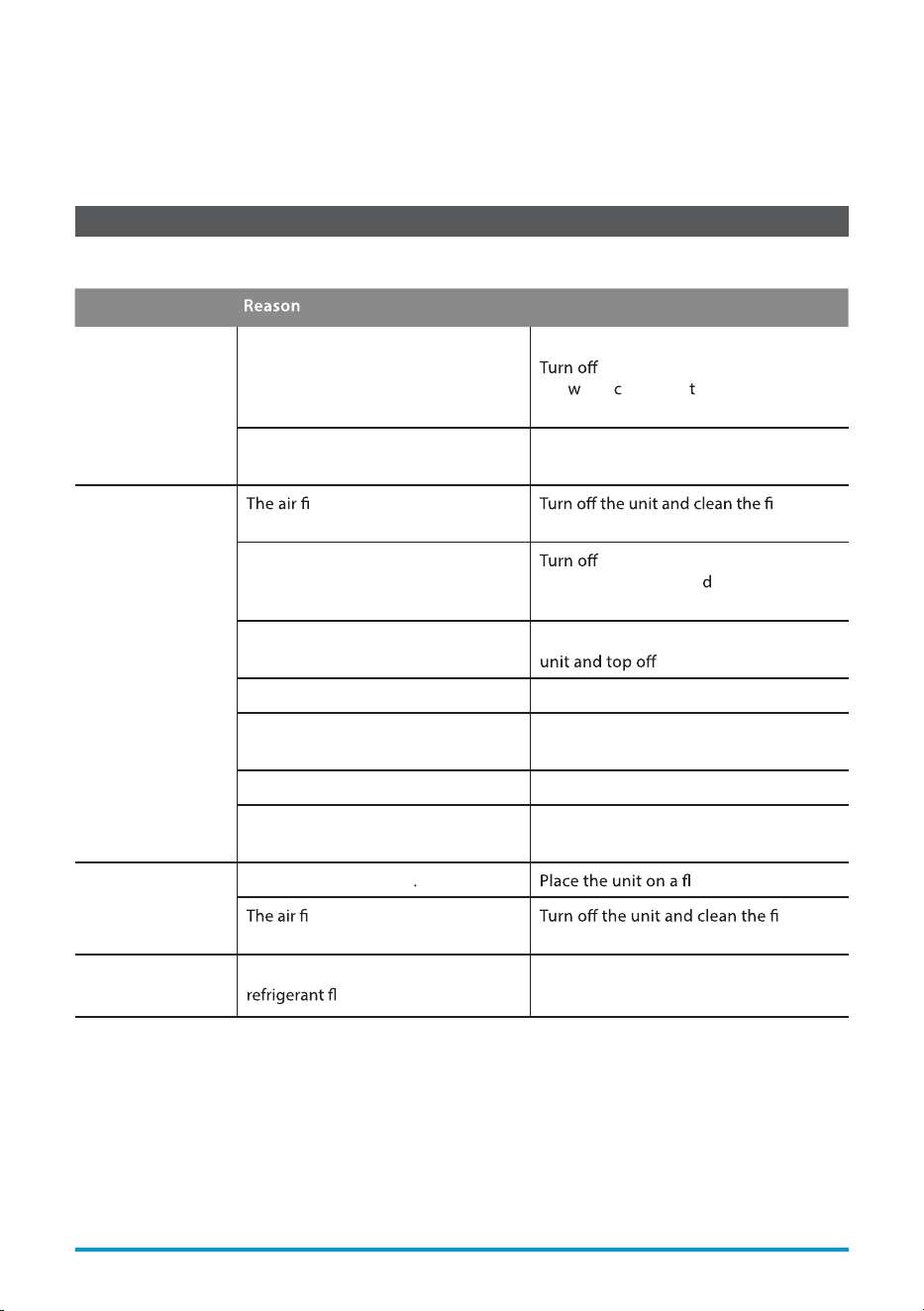
Common Issues
The following problems are not a malfunction and in most situations will not require repairs.
Problem
Solution
Unit does not turn
on when pressing
ON/OFF button
P1 Protection Code.
The water collection tray is full.
the unit, drain the water from
the
ater ollection ray and restart
the unit.
In COOL mode: room temperature is
lower than the set temperature.
Check the set temperature.
Unit does not cool
well
lter is blocked with dust or
animal hair.
lter
according to instructions.
Exhaust hose is not connected or is
blocked.
the unit, disconnect the hose,
check for blockage an
reconnect the
hose.
The unit is low on refrigerant. Call a service technician to inspect the
refrigerant.
Temperature setting is too high. Decrease the set temperature.
The windows and doors in the room
are open.
Make sure all windows and doors are
closed.
The room area is too large. Double-check the cooling area.
There are heat sources inside the
room.
Remove the heat sources if possible.
The unit is noisy
and vibrates too
much
The ground is not level
at, level surface.
lter is blocked with dust or
animal hair.
lter
according to instructions.
The unit makes a
gurgling sound
This sound is caused by the
ow inside the unit.
This is normal.
Page 28 User Manual
TROUBLESHOOTING TIPS
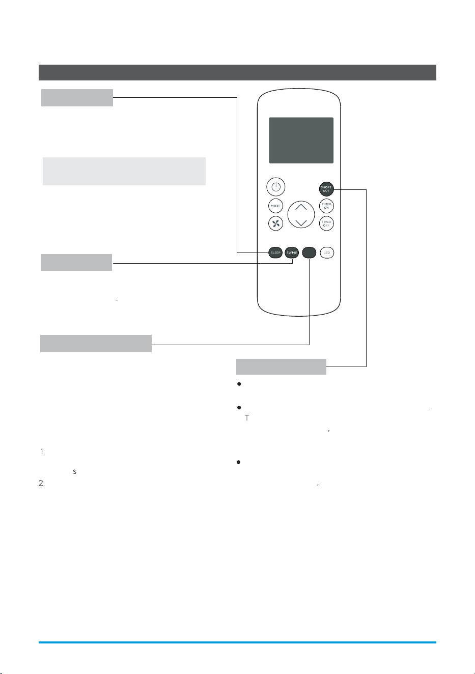
snoitac ificepS lortnoC etomeR
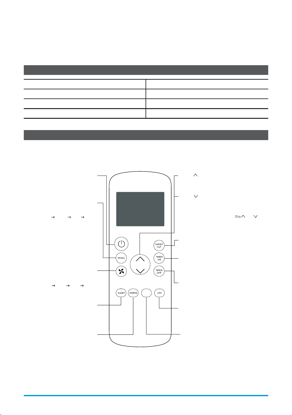
Function Buttons
Before you begin using your new air conditioner, make sure to familiarize yourself with its remote
control. The following is a brief introduction to the remote control itself. For instructions on how to
operate your air conditioner, refer to the Operating Instructions section of this manual.
Model
Rated voltage 3.0V (Dry batteries R03/LR03x2)
Signal receiving range 26 ft. (approx. 8 m)
Environment 23°F ~ 140°F (-5°C ~ 60°C)
Turns the unit on or off.
SWING
Starts and stops
louver movement.
SLEEP
Saves energy during
sleeping hours.
Selects fan speeds in the
following order:
AUTO LOW MED HIGH
MODE
Scrolls through operation modes
as follows:
AUTO COOL DRY FAN
NOTE:
Please do not select HEAT mode
if the machine you purchased is
cool-only type. Heat mode is not
supported by cool-only models.
ON/OFF
FAN SPEED
MyTemp
TEMP
Increases temperature in 1° increments.
Max. temperature is 86°F (30°C).
TEMP
Decreases temperature in 1° increments. Min.
temperature is 6 °F (1 °C).
NOTE: Pressing and holding
and
buttons together for 3 seconds will alternate
the temperature display between the °F & °C
scale.
SHORT CUT
Sets and activates your favorite pre-settings.
TIMER ON
Sets timer to turn unit on.
TIMER OFF
Sets timer to turn unit off.
LED
Turns the AC’s LED display on and off.
MyTemp
Turns the MyTemp feature on and off.
RG57H4(B2)/BGCEFU1
User Manual Page 29
REMOTE CONTROL AND
APP INSTRUCTIONS
0 6
Handling the Remote Control
NOT SURE WHAT A FUNCTION DOES?
Refer to the Operating Instructions section of this manual for a detailed description of the functions
available using the remote.
NOTICE
Button designs on your unit may dier slightly from the example shown.
If the unit does not have a specic function, using that function’s button on the remote control
will have no eect.
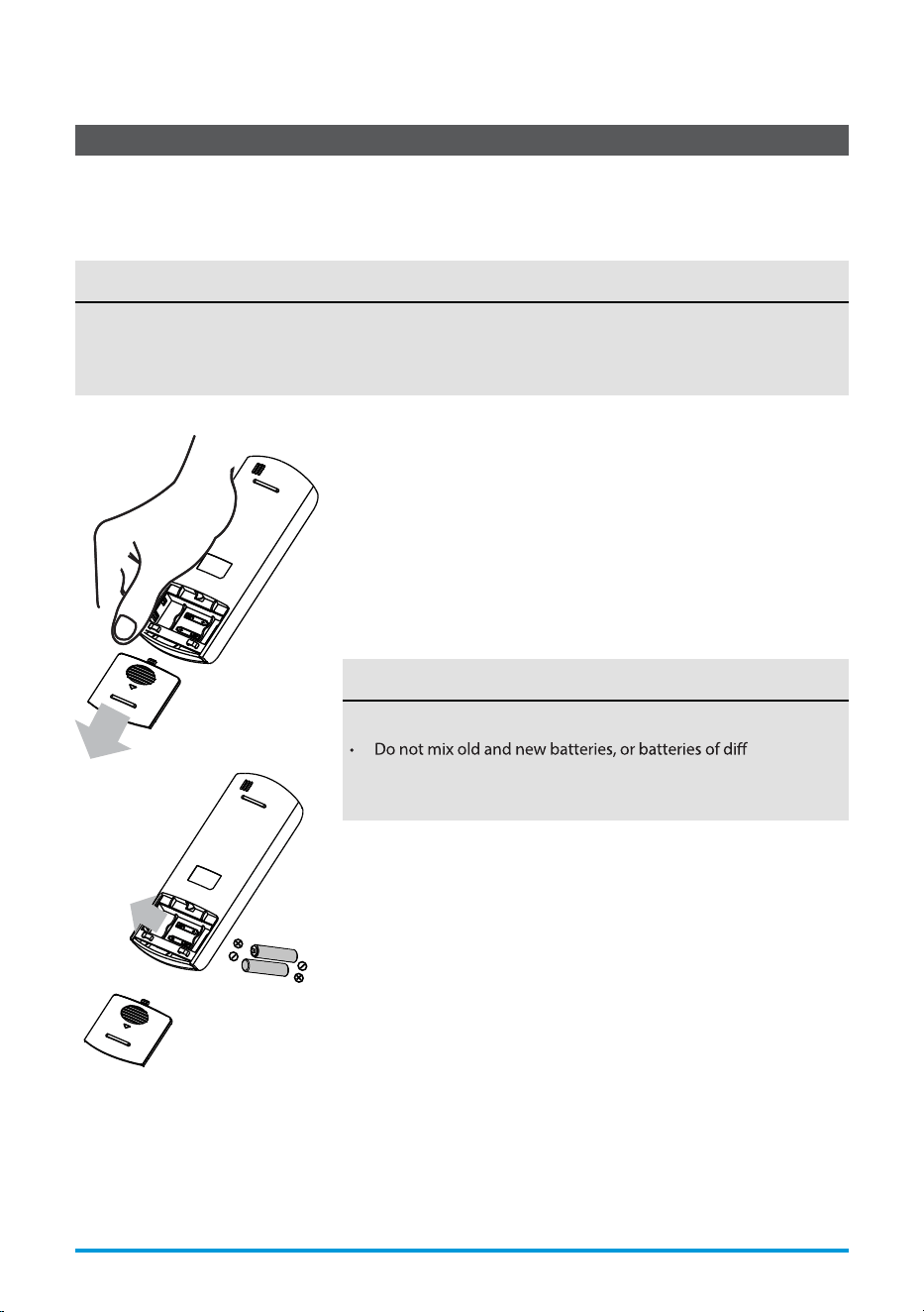
INSERTING AND REPLACING BATTERIES
Your air conditioning unit comes with two AAA batteries. Insert the
batteries in the remote control before use.
1. Slide the back cover of the remote control downward, exposing
the battery compartment.
2. Insert the batteries, paying attention to align the (+) and (-) ends
of the batteries with the symbols inside the battery compartment.
3. Slide the battery cover back into place.
BATTERY DISPOSAL
Ensure used batteries are disposed of properly.
TIPS FOR USING REMOTE CONTROL
• The remote control must be used within 26 feet / 8 meters of
the unit.
• The unit will beep when it receives a signal from the remote.
Curtains, other materials and direct sunlight can interfere with
the IR signal receiver.
• In order to properly t
ransmit a command, the ON/OFF indicator
must be illuminated on the remote’s display. (See the Remote
LED Screen Indicators section for more information.)
BATTERY NOTES
For optimum product performance:
erent types.
• Do not leave batteries in the remote control if you don’t plan
on using the device for more than 2 months.
Page 30 User Manual
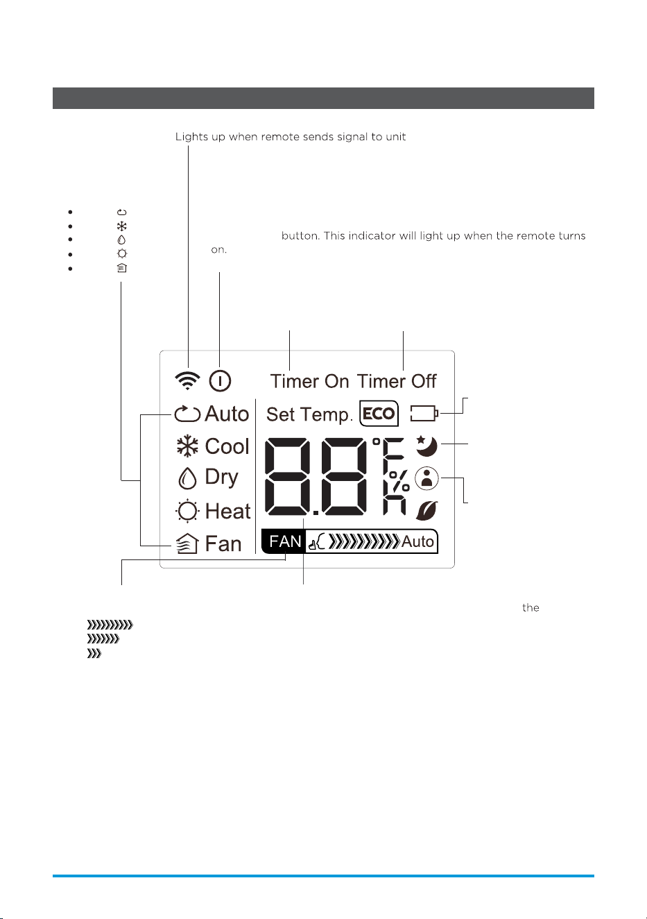
AUTO
COOL
DRY
HEAT
FAN
Transmission Indicator
MODE display
Displays the current
mode, including:
TIMER ON display
Displays when
TIMER ON is set
TIMER OFF display
Displays when
TIMER OFF is set
Battery display
Low battery detection
SLEEP display
Displays when SLEEP
function is activated
FAN SPEED display
Displays selected FAN SPEED:
HIGH
MED
LOW
This display is blank when
set to AUTO speed.
Temperature/Timer display
Displays the set temperature by default, or
timer
setting when using TIMER ON/OFF functions:
- Temperature range: 62°F-86°F (17°C-30°C)
- Timer setting range: 0-24 hours
This display is blank when operating in FAN mode.
ON/OFF display
Appears when the remote is enabled and can send a signal to the unit.
If you would like to turn the remote off without affecting the unit, point
the remote away from the unit and press the ON/OFF button.
To turn the remote on, point the remote away from the unit and press
the ON/OFF
The unit will not receive commands from the remote if this
indicator is not illuminated.
MyTemp display
Indicates that the
MyTemp function is on
Remote LED Screen Indicators
User Manual Page 31
Basic Functions
SETTING THE DESIRED TEMPERATURE
The operating temperature range for this unit is 62°F-86°F (17-30°C).
You can increase or decrease the set temperature in 1°F or 1°C increments.
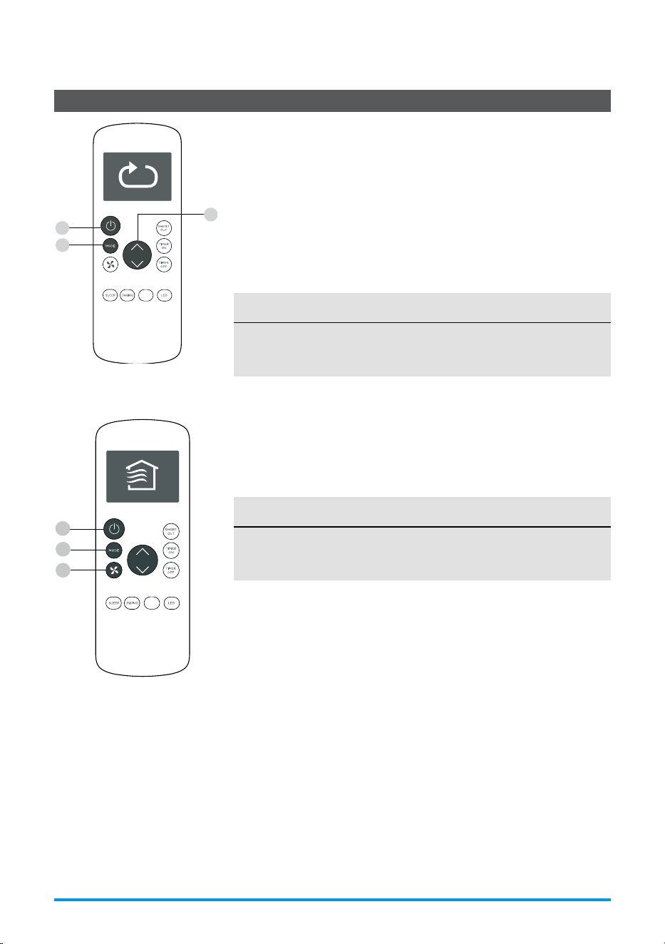
Changing the Mode
1. To change the operating mode, press the MODE button until the
desired mode appears on the remote’s display.
2. Set the desired temperature.
NOTICE
If the unit does not change when the button is pressed, check that
the ON/OFF indicator is illuminated. If it is not, point the remote at
the unit and press the ON/OFF button.
NOTICE
If the unit does not change when the button is pressed, check that
the ON/OFF indicator is illuminated. If it is not, point the remote at
the unit and press the ON/OFF button.
Changing the Fan Speed
To change the fan speed, press the FAN button until the desired fan
speed appears on the remote’s display.
1
3
2
FOLLOW
ME
MyTemp
1
2
3
FOLLOW
ME
MyTemp
Page 32 User Manual
Timer Functions
NOTICE
This number indicates the amount of time after the current time
after which you want the unit to turn on.
For example, if you set TIMER ON for 2 hours, “2.0h“ will appear on
the screen, and the unit will turn on after 2 hours.
Your air conditioning unit has two timer-related functions:
TIMER ON - sets the amount of time after which the unit will
automatically turn on.
TIMER OFF - sets the amount of time after which the unit will
automatically turn o.
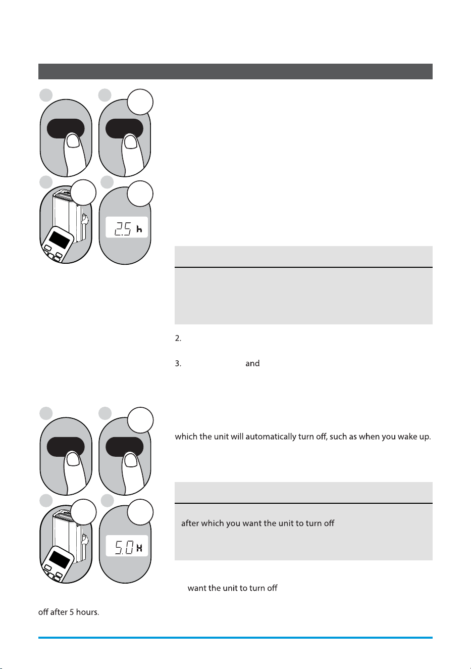
TIMER ON Function
The TIMER ON function allows you to set a period of time after
which the unit will automatically turn on, such as when you come
home from work.
1. Press the TIMER ON button. By default, the last time period that
you set and an “
h” (indicating hours) will appear on the display.
2sec
S
L
x5
1
3
2
4
TIMER ON TIMER ON
Example: Setting unit to turn
on after 2.5 hours.
Press the TIMER ON button repeatedly to set the time that you
want the unit to turn on.
Wait 2 seconds then the TIMER ON function will be
activated. The digital display on your remote control will then
return to the temperature display.
2sec
x10
F
1
3
2
4
TIMER OFF TIMER OFF
Example: Setting unit to turn
TIMER OFF Function
The TIMER OFF function allows you to set a period of time after
1. Press the TIMER OFF button. By default, the last time period that
you set and an “h” (indicating hours) will appear on the display.
2. Press the TIMER OFF button repeatedly to set the time that you
.
This number indicates the amount of time after the current time
.
For example, if you set TIMER OFF for 2 hours, “2.0h“ will
appear on the screen, and the unit will turn o after 2 hours.
NOTICE
User Manual Page 33
ON/OFF
MODE
FAN
SHORT
CUT
TIMER ON
TIMER OF
F
TEMP
S
L
E
EP
1
ON/OFF
MODE
F
AN
SHORT
CUT
TIMER ON
TIMER OF
F
TEMP
S
LEEP
1sec
sec
Timer Functions (cont.)
3. Wait 2 seconds then the TIMER OFF function will be activated.
The digital display on your remote control will then return to
the temperature display.
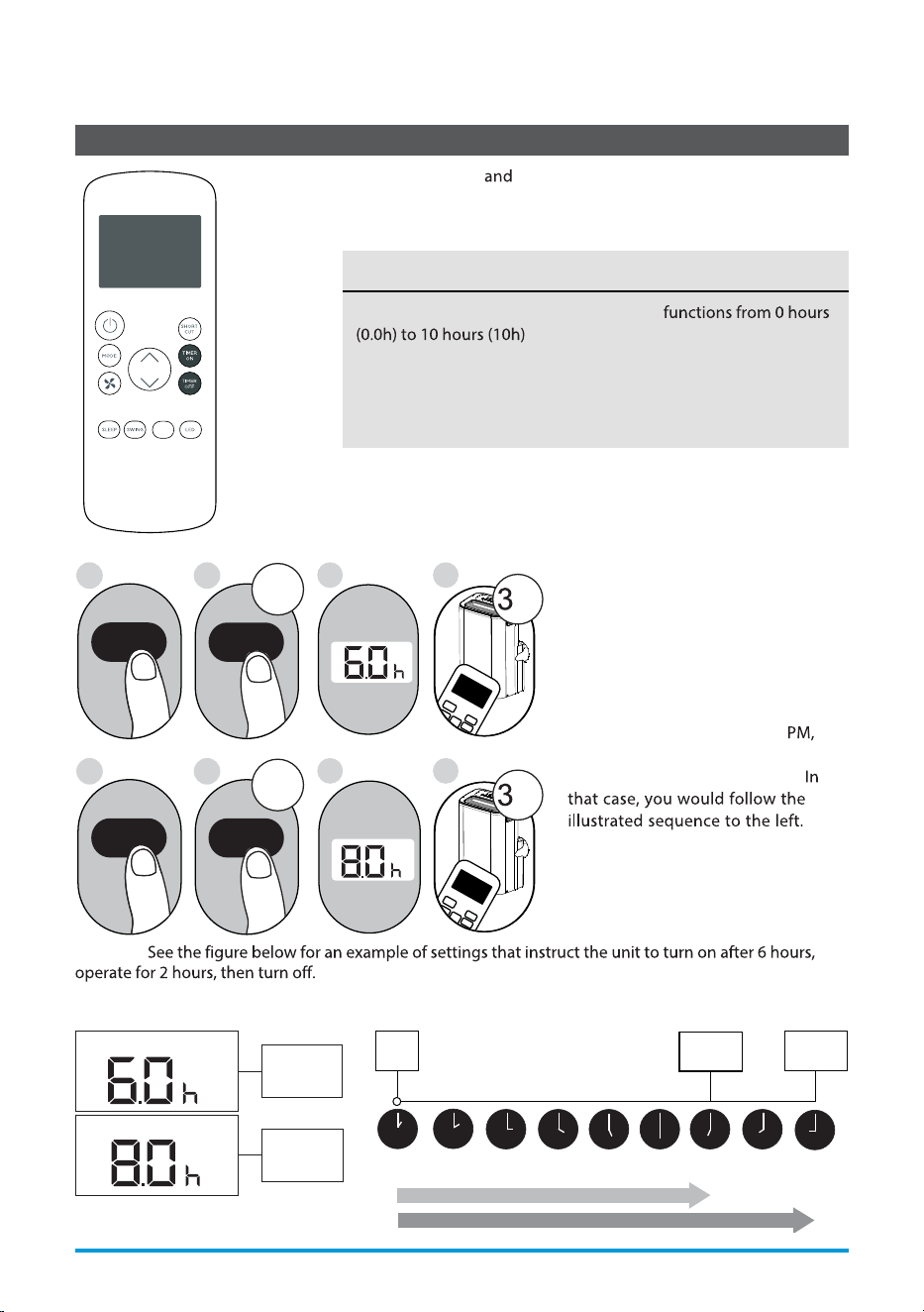
NOTICE
When setting the TIMER ON or TIMER OFF
, the time will increase in 30 minute
increments with each press. From 10 hours (10h) to 24 hours (24h),
it will increase in 1 hour increments. The timer will revert to zero
after 24 hours.
You can turn o either function by setting the timer to “0.0h“.
4
8
1
TIMER ON
X12
2
TIMER ON
5
TIMER OFF
X16
6
TIMER OFF
3
7
Setting Both TIMER ON And
TIMER OFF At The Same Time
Keep in mind that the time periods
you set for both functions refer to
hours after the current time. For
example, say that the current time
is 1:00 PM, and you want the unit to
turn on automatically at 7:00
operate for 2 hours, then
automatically turn o at 9:00 PM.
Timer On
Timer O
Timer is set
To turn ON
6 hours from
current time
Timer is set
To turn OFF
8 hours from
current time
Current
Time 1PM
2PM 3PM
4PM 5PM
6PM 7PM 8PM 9PM
Unit turns
ON
Unit turns
OFF
6 hours later
8 hours later
Timer
Starts
Example:
Your remote display
T i m e r o n
Continue
to press
TIMER ON
or
TIMER OFF
until desired
time is
reached.
FOLLOW
ME
MyTemp
Page 34 User Manual
ON/OFF
MODE
SHORT
CUT
TIMER ON
TEMP
sec
ON/OFF
MODE
SHORT
CUT
TIMER ON
TEMP
sec
How to Use the Advanced Functions
SHORTCUT Function
SWING Function
MyTemp Function
SLEEP Function
The SLEEP function is used to decrease
energy use while you sleep (and don’t need
the same temperature settings to stay
comfortable).
The MyTemp function enables the remote
control to measure the temperature at its
current location.
Press the button to activate function.
The remote control will send temperature
signal
to the unit every three minutes.
Press the button again to turn off
this function.
Used t
o stop or start louver movement and set the
desired up/down air flow direction. The louver
angle changes in 6
degree increments with each
press (not all models). By pressing for more than 2
seconds, the louver auto swing feature is activated.
Used to restore the current settings or resume
previous settings.
Push this button when remote controller is on
he system will automatically revert back to
the previous settings
including operating
mode, setting temperature, fan speed level and
sleep feature (if activated).
By pressing for more than 2 seconds, the
system will automatically store the current
operation settings
including operating mode,
setting temperature, fan speed level and sleep
feature (if activated).
Note:
The SLEEP function is not
available in FAN or DRY mode.
MyTemp
User Manual Page 35
When using AUTO, COOL, measuring ambient
temperature from the remote control (instead
of from the indoor unit itself) will enable the
air conditioner to optimize the temperature
around you and ensure maximum comfort.
This device complies with part 15 of the FCC Rules. Operation is subject to the following two
conditions: (1) This device may not cause harmful interference, and (2) this device must accept
any interference received, including interference that may cause undesired operation.
Note: This equipment has been tested and found to comply with the limits for a Class B digital
device, pursuant to part 15 of the FCC Rules. These limits are designed to provide reasonable
protection against harmful interference in a residential installation. This equipment generates,
uses and can radiate radio frequency energy and, if not installed and used in accordance with
the instructions, may cause harmful interference to radio communications. However, there is no
guarantee that interference will not occur in a particular installation.
If this equipment does cause harmful interference to radio or television reception, which can be
and on, the user is encouraged to try to correct the
interference by one or more of the following measures:
• Reorient or relocate the receiving antenna.
• Increase the separation between the equipment and receiver.
erent from that to which the receiver is
connected.
• Consult the dealer or an experienced radio/TV technician for help.
NOTICE
User Manual Page 37
1
How to use Matter
Connect Your Air Conditioner through Matter
Make sure your mobile device is connected to your wireless router.
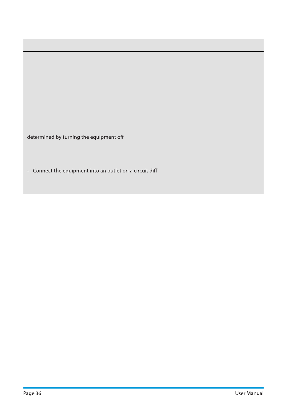
Turn on Bluetooth on your mobile device.
Step 2: Turn on Bluetooth
Settings
Bluetooth
Bluetooth
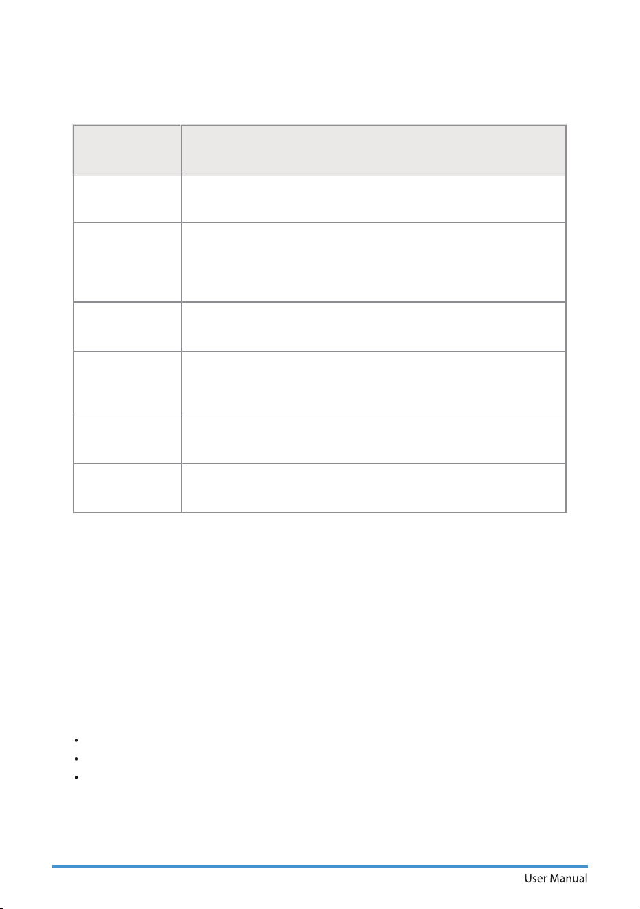
Step 1: Connect to smart speaker
Select your preferred ecosystem (Alexa, Google Home or Apple Home) and
make sure you’ve got one of their Matter enabled products (such as their
smart speakers) connected to your wireless router.
Wireless router should support and turn on IPv6. Please make sure your
smartphone connect to 2.4G but not 5G network.
For best Matter compatibility, connect the AC to the Alexa, Google Home or
Apple Home ecosystems along with at least one of their respective Matter
enabled smart speakers.
Apple Home Google Home Alexa
Page 38
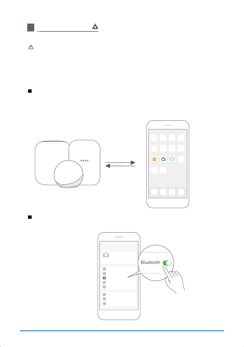
Open the Alexa, Google Home, Apple Home app on your mobile device.
Step 4: Open app
Apple home Google home Alexa
Hold down the CONNECT button for 3 seconds to begin the pairing
process (“AP” will appear on the AC’s display).
Step 3: Enter AP mode
AP
CONNECT
User Manual Page 39
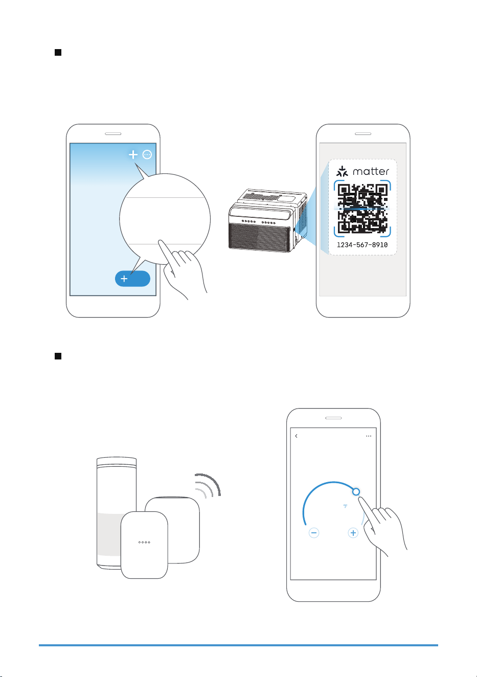
Tap the “+” and “Add Device/Accessory” or tap "+Add" in your app and then
select Matter device and scan the Matter QR code found on the side of the
AC device. Follow the respective instructions in the Alexa, Google Home or
Apple Home app to complete the pairing process.
Step 5: Scan matter QR code
After pairing is successful, you can control your AC’s temperature and mode
settings, etc. through the respective ecosystem app and/or smart speaker.
Step 6: Control device
Air conditioner
76
scan
Matter QR code
Add
Add Device/Accessory
Page 40
NOTE:
Setup processes and features may vary between ecosystems.
Make sure the Matter enabled app is up to date to ensure the best experience.
Periodically, we will update the device’s software to improve the experience.
Device software updates can be accomplished through the SmartHome app.
App & Smart Speakers can support Matter only when using these
versions or above.
9094439556
Google Play services min version: 22.36.15
Google Home app (GHA) min version: 2.58.24.1-dogfood
Google Hub öSNXBSF min version: 1.56.324896
(appears on hub as Chromecast öSNXBSF version)
2.2.536317
16.5
Device Version
iOS 16.5iPhone
Apple Home
Pod
Alexa Echo
Device
Android
Google
Home Hub
Alexa App
User Manual Page 41
2
How to use SmartHome App
Ensure that your mobile phone is connected to the wireless network. Bluetooth
must be turned on. The device must also be powered up.
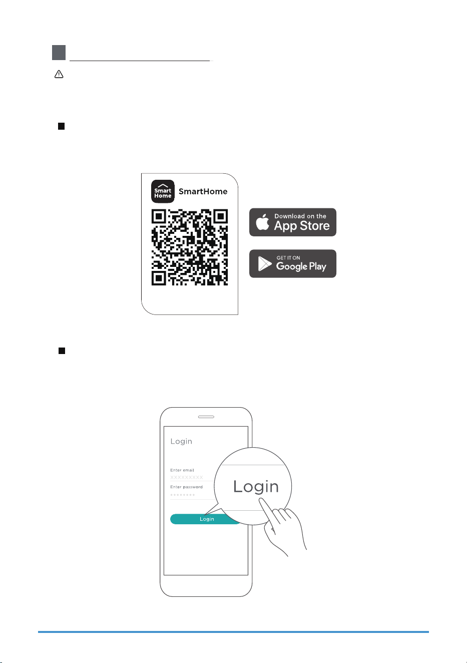
Scan the QR code below to download the SmartHome app from app store or
search for it directly on the Google Play Store or Apple's App Store.
Step 1: Download the SmartHome app
Open the SmartHome app. Log in directly if you have an existing SmartHome
account or create a new account. Alternatively, you can also use a 3rd party
login platform.
Step 2: Log in
Download the app
& activate product
Page 42
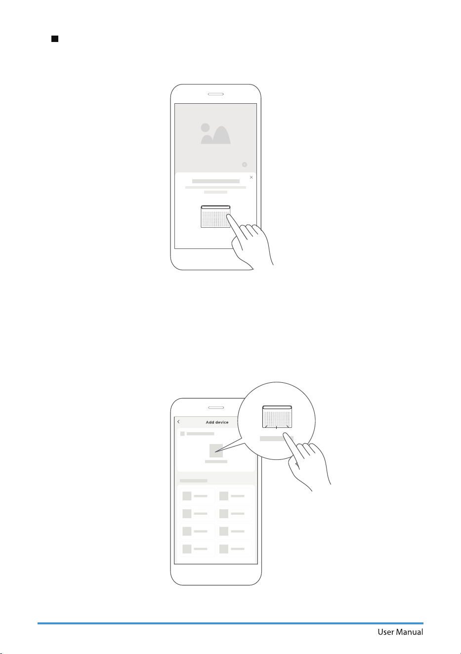
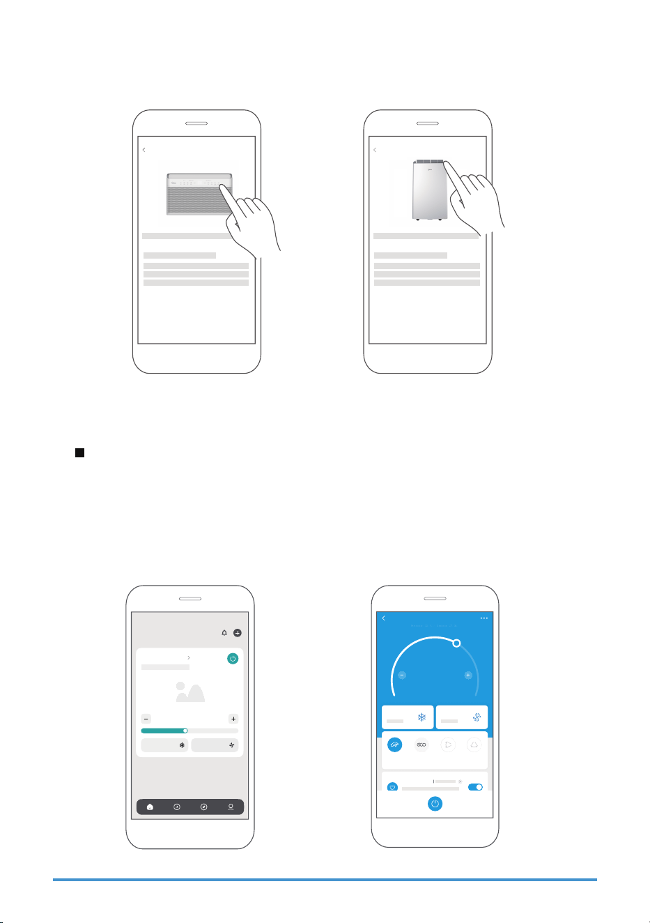
1) When you log in, you may see the message "Smart devices discovered nearby".
Tap to add your device.
2) If no such message appears, proceed as follows: Tap on "+" and select your
device in the list of nearby available devices.
*GZPVSEFWJDFJTOPUMJTUFEQMFBTFBEEZPVSEFWJDFNBOVBMMZöSTUTFMFDUJOHUIF
device category e.g. Window AC.
Step 3: Connecting the device
User Manual Page 43
After pairing successfully, a card will be created for the device in the SmartHome
app.
Shortcuts for basic functions will appear on the card such as changing the
UFNQFSBUVSFPSTXJUDIJOHUIFEFWJDFPOPSPò
Tapping on the card, will reveal additional features and settings. The actual UI
EFTJHONBZMPPLEJòFSFOUGSPNFYBNQMFTEVFUPBQQVQEBUFT
Step 4: Controlling the device
3) Follow the steps in the app to connect your device to the wireless network. If
your device fails to connect, follow the additional instructions in the app.
Add device
For Window AC For Portable AC
Add device
Air Conditioner
Cool Auto
26
°C
SmartHome
26.0
ć
Fan speed
75%
Cool
Mode
Fan speed
Mode
Device name
ć
ć
Outdoor 32
/ Indoor 27.5
My Favorite
Boost ECO Vertical
Swing
Horizontal
Swing
Sleep Curve

Page 44
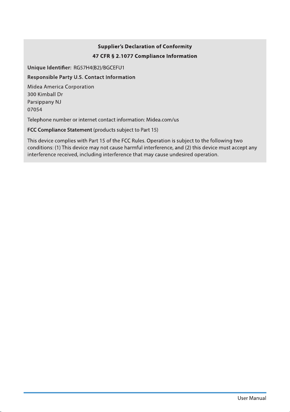
FCC ID: 2ADQOMDNA23
IC: 12575A-MDNA23
This device complies with Part 15 of the FCC Rules and Industry Canada’s
licenceexempt RSSs.
Operation is subject to the following two conditions:
(1) This device may not cause interference; and
(2) This device must acceptany interference, including interference that may
cause undesired operation of the device.
Only operate the device in accordance with the instructions supplied. Changes
PSNPEJöDBUJPOTUPUIJTVOJUOPUFYQSFTTMZBQQSPWFECZUIFQBSUZSFTQPOTJCMFGPS
compliance could void the user's authority to operate the equipment. This device
complies with FCC radiation exposure limits set forth for an uncontrolled
environment. In order to avoid the possibility of exceeding the FCC radio
frequency exposure limits, human proximity to the antenna shall not be less
than 20cm (8 inches) during normal operation.
Declaration of conformity
This equipment has been tested and found to comply with the limits for a Class B
digital device, pursuant to part 15 of the FCC Rules. These limits are designed to
provide reasonable protection against harmful interference in a residential
installation.
This equipment generates, uses and can radiate radio frequency energy and, if
not installed and used in accordance with the instructions, may cause harmful
interference to radio communications. However, there is no guarantee that
interference will not occur in a particular installation. If this equipment does cause
harmful interference to radio or television reception, which can be determined by
UVSOJOHUIFFRVJQNFOUPòBOEPOUIFVTFSJTFODPVSBHFEUPUSZUPDPSSFDUUIF
interference by one or more of the following measures:
--Reorient or relocate the receiving antenna.
--Increase the separation between the equipment and receiver.
$POOFDUUIFFRVJQNFOUJOUPBOPVUMFUPOBDJSDVJUEJòFSFOUGSPNUIBUUPXIJDI
the receiver is connected.
--Consult the dealer or an experienced radio/TV technician for help.
NOTE:

User Manual Page 45
3
SPECIFICATION
This device is in compliance with the essential requirements and other relevant
provisions of Directive 2014/53/EU, in order to avoid the possibility of exceeding
the radio frequency exposure limits, human proximity to the antenna shall not be
less than 20cm during normal operation. (European Union products only)
Unit model: MPX0812CWRU, MPX1011CWRU
Wireless Module Model: US-SK109
Antenna Type: Printed PCB Antenna
Wireless: 2400 - 2483.5MHz, TX Power: < 20dBm
Operation Temperature: 0°C~45°C/32°F~113°F
Operation Humidity: 10%~85%
Power Input: DC 5V/500mA
BLE: 2402 - 2480MHz, TX Power: < 10dBm
Page 46

WARRANTY
Air Conditioner Limited Warranty
Your product is protected by this Limited Warranty:
Warranty service must be obtained from Midea Consumer Services or an authorized Midea servicer.
Warranty
•
•
Three Year Full warranty from the date of delivery or the purchase date, whichever is later.
The date of delivery establishes the warranty period, should service be required.
Midea, through its authorized servicers will:
• Pay all costs for reparing or replacing parts of this appliance which prove to be defective in materials
or workmanship.
Consumer will be responsible for:
• Diagnostics, removal, transportation and reinstallation cost required because of service.
• Costs of serv
ice calls that are a result of items listed under NORMAL RESPONS
ABILITIES OF THE CONSUMER**
Midea replacement parts shall be used and will be warranted only for the original warranty.
NORMAL RESPONSABILITIES OF THE CONSUMER**
This warranty applies only to products in ordinary household use, and the consumer is responsible for
the items listed below:
1. Proper use of the appliance in acor
dance with instructions provided with the product.
2. Routine maintenance and cleaning necessary to keep the good working con
dition.
3. Proper installation by an authorized service professional in accordance with instructions provided with the
appliance and in accordance with all local plumbing, electrical and/or gas codes.
4. Proper connection to a grouded power supply of sufficient voltage, replacement of blown fuses, repair of
loosen connections or defects in house wiring.
5. Expenses for making the appliance accessible fo
r servicing.
6. Damages to finish after installation.
EXCLUSIONS
This warranty does not cover the following:
1) Failure caused by damage to the unit while in your possesion (other than damage caused by
defect or malfunction), by its
improper installation, or by unreasonable use of the unit, including
without limitation, failure to provide reasonable and necessary maintenance or to follow the written
installation and Operating Instructions.
2) Damages caused by services performed by persons other than those authorized by Midea customer
service; or external causes such as abuse, misuse
, inadequate power supply or acts of God.
3) If the unit is put to commercial, business, rental, or other use or application other than for consumer
use, we make no warranties, express or implied, including but not limited to, any implied warranty of
merchantability or fitness for use or purpose.
4) Products without original serial numbers or products that have serial numbers which have been altered
or cannot be readily determined.
NOTICE: Some states do not allow the exclusions or limitation of incidental or consequential damages.
So this limitation or exclusion may not apply to you.
IF YOU NEED SERVICE
Keep your bill of sale, delivery slip, or some other appropriate payment Record.
The date on the bill establishes the warranty period, should service be required.
If service is performed, its your best interest to obtain and keep all receipts.
This written warranty gives you specific legal rights. You may also have other rights that v
ary
from state to state.
Service under this warranty must be obtained by following these steps, in order:
1) Contact Midea Consumer Services or an authorized Midea services at 1 866 646 4332.
2) If there is a question as to where to obtain service, contact our consumer relations Departament.
User Manual Page 47
www.midea.com
© Midea 2025 all rights reserved
CW0011UI-QB(NEW)A
20250822
16122000A82395