
1
USER
MANUAL
High-Performance Metal Detector!
READ CAREFULLY BEFORE OPERATION
OF THE DEVICE!
LEGAL DISCLAIMERS
Comply with applicable laws and regulations governing use
of metal detectors while using this detector. Do not use the
detector without authorization in protected or archeological
sites. Do not use this detector around unexploded ordnance or in
restricted military zones without authorization. Notify appropriate
authorities with details of any historical or culturally significant
artifacts you find.
WARNINGS
The LEGEND 2 is a state-of-the-art electronic device. Do not
assemble or operate the device before reading the user manual.
Do not store the device and search coil under extremely low or
high temperatures for extended periods. (Storage Temperature:
- 20°C to +45°C / - 4°F to +113°F)
The device features an IP68 waterproof rating, allowing submersion
up to 5 meters (16 ft), excluding the Bluetooth® headphones.
Pay attention to the items below after using the device especially
under salty water:
1. Rinse the system box, shaft, and coil with tap water, making sure
all saltwater is fully removed from the connectors.
2. Do not use any chemicals for cleaning and/or for any other
purposes.
3. Wipe the screen and the shaft dry with a soft, non-scratch
cloth.
Protect the detector from impact during use. When shipping,
place it in the original carton and secure it with shock-resistant
packaging.
The LEGEND 2 metal detector may only be disassembled and
repaired by Nokta Authorized Service Centers. Unauthorized
disassembly/intrusion into the metal detector control housing for
any reason voids the warranty.
IMPORTANT!
Do not use the device indoors, where surrounding metals may
cause continuous target signals. Use only in open outdoor areas.
Keep other detectors and electromagnetic devices a minimum of
10 m (30 ft) from the device.
Do not carry any metal objects while using the device. Keep the
device away from your shoes while walking. Metal on your body
or inside your shoes may be detected as targets.
ASSEMBLY
INTRODUCTION TO THE DEVICE
DISPLAY
BATTERY INFORMATION
CORRECT USE
QUICK GUIDE
COMMON AND MODE-BASED SETTINGS
SEARCH MODES
USER PROFILE
MUTE FUNCTION
TARGET ID
GROUND BALANCE
PINPOINT
FERROCHECK™
MINERALIZATION INDICATOR
TARGET DEPTH
QUICK SETTINGS
1. Sensitivity
2. Frequency
3. Discrimination Patterns
4. Recovery Speed
5. Bottle Cap Rejection
5.1 Iron Rejection in Relic Mode
6. Iron Filter
7. Stability in Beach Mode
CONTENTS
: 3-6
: 7
: 8
: 9
: 10
: 11
: 11-12
: 12-14
: 14-15
: 15
: 16
: 16-18
: 18
: 19
: 20
: 20
: 20-25
: 21
: 22
: 23
: 24
: 24
: 24
: 25
: 25
1

SETTINGS
1. Volume Level
2. Frequency Shift
3. Ground Suppressor
4. Deep Target Identification
5. Notch (Accepting and Rejecting IDs)
6. Screen and Keypad Backlight
7. Vibration
8. LED Flashlight
AUDIO OPTIONS
1. Speaker
2. Bone Conduction Headphones
3. Bluetooth® Headphones
4. Multiple Audio Output
5. Wired Headphones
SUB-SETTINGS
1. Number of Tones
2. Tone Volume
3. Tone Frequency
4. Tone Break
5. Threshold Level
6. Threshold Frequency
7. Audio Gain
8. Clock and Usage Duration
9. FerroCheck™ / Mineralization Option
WARNING MESSAGES
REVERTING BACK TO FACTORY DEFAULTS
SOFTWARE UPDATE
HEADPHONES
TECHNICAL SPECIFICATIONS
RECOMMENDED ACCESSORIES
: 25-30
: 26
: 26-27
: 27
: 27
: 28-29
: 29
: 30
: 30
: 30-31
: 31
: 31
: 31
: 31
: 31
: 32-40
: 32-33
: 34
: 35-36
: 36-37
: 38
: 39
: 39
: 40
: 40
: 41
: 41
: 41
: 41
: 42
: 43
CONTENTS (Continued)
2
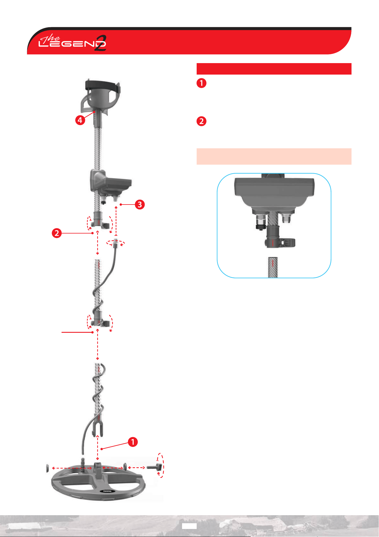
ASSEMBLY
After inserting the washers onto the lower shaft, attach the
lower shaft to the search coil and secure it by tightening the
screw. Do not overtighten.
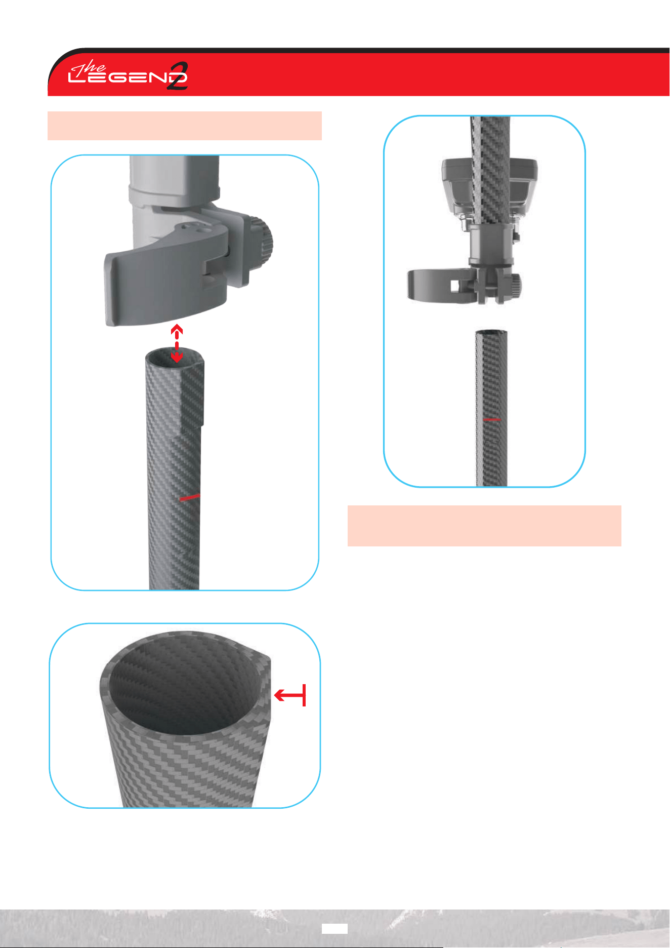
Open the lever latches to connect the middle shaft to the
upper and lower shafts. Adjust the length to your height,
tighten the side screws, and close the latches to secure.
IMPORTANT! During assembly, make sure that the red lines on
the shafts are aligned to overlap, as shown in below.
3
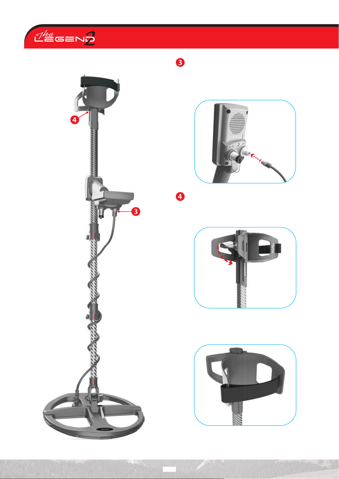
Wind the search coil cable around the shaft without
overstretching (Figure A), then plug the connector into the
search coil input socket on the system box (Figure B) and secure it
by tightening the nut until you hear clicks.
Figure B:
If you want to adjust the armrest, open the latch. Once it
reaches your desired height, close the latch to secure it.
(Figure C)
Figure C:
Attach the armrest strap as shown in the picture (Figure D) and
tighten it according to the width of your arm.
Figure D:
4
Figure A
1
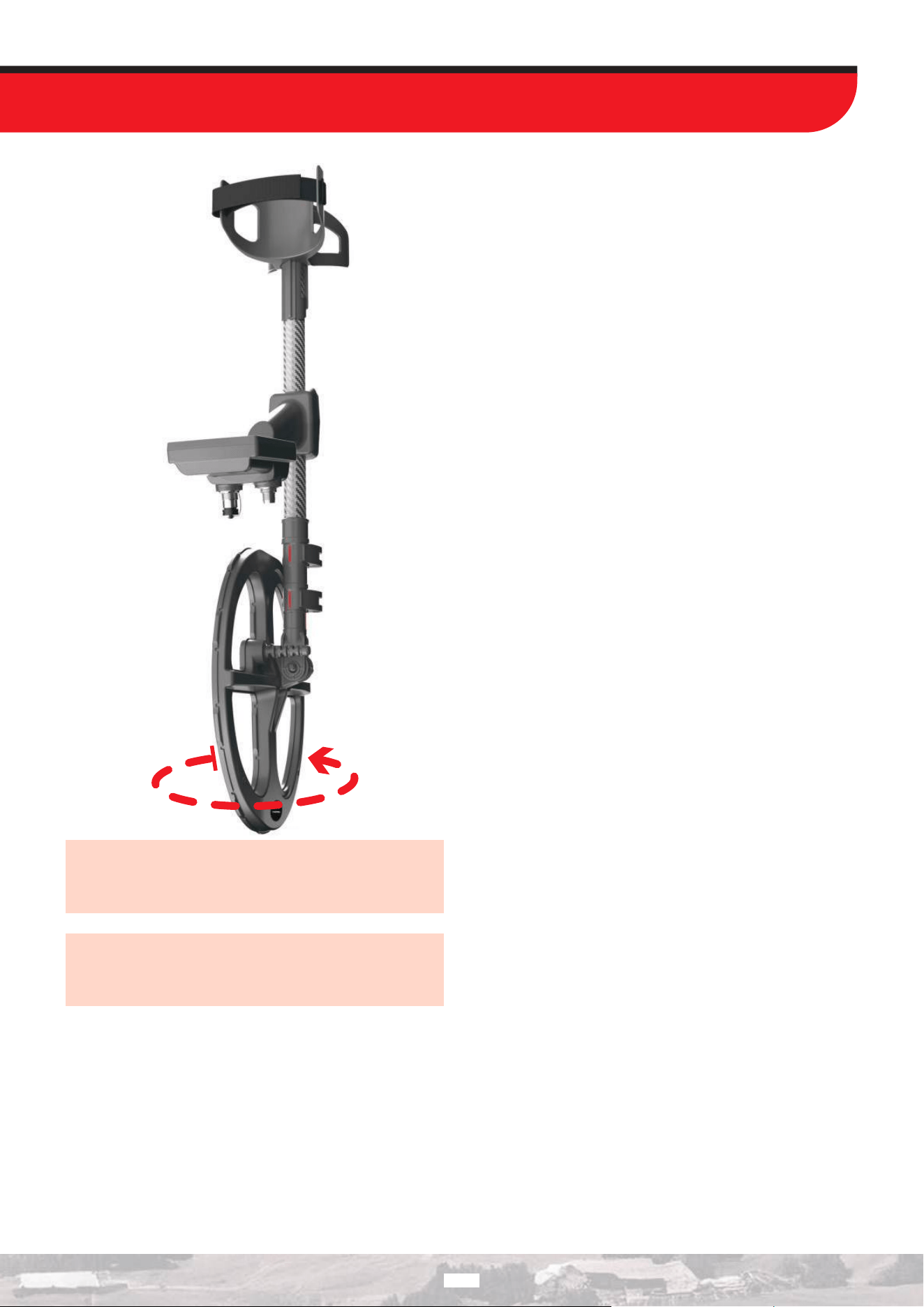
IMPORTANT! When the red lines on the shafts are aligned and
the shafts are set to their shortest position, the search coil
becomes rotatable. By rotating and folding the search coil, you
can place the detector in a compact carrying position.
IMPORTANT! To prepare the detector for use from the compact
position, the system box and the search coil must be aligned
in the same direction, and the red lines on the shafts must be
fully aligned. Otherwise, the shafts cannot be extended.
5
6
IMPORTANT! The flat section on the rear of the detector shafts
ensures a tight fit.
IMPORTANT! The red lines on the rear of the shafts indicate
the maximum length to which the shafts can be extended. Do
not exceed this limit.
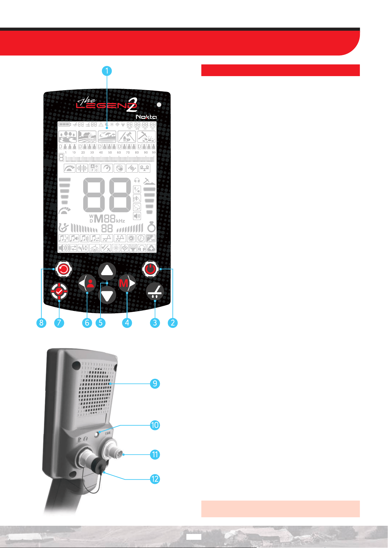
INTRODUCTION TO THE DEVICE
1. LCD Screen
2. Power / Settings Button
Press and hold the Power / Settings button for 2 seconds to turn
the device on. Press once to enter or exit settings. To turn the
device o, press and hold the Power / Settings button.
Note : While in settings, pressing and holding the Power / Settings
button will not turn the device o.
3. Ground Balance Button
Press the Ground Balance button once to enter or exit the ground
balance menu. Press and hold the Ground Balance button to
perform automatic ground balancing.
4. Right Button
On the main screen, the Right button navigates between modes,
while in the settings menu, it navigates through the settings
options.
5. Up and Down Buttons
Use the Up and Down buttons to adjust the selected quick setting
on the main screen or to change any setting value in the settings
menu.
6. Left Button
On the main screen, use the Left button to switch between user
profiles. Press and hold to save or delete a profile. In the settings
menu, use it to navigate between options.
7. Pinpoint & Accept/Reject Button
On the main screen, the Pinpoint & Accept/Reject button activates
the Pinpoint mode. Press once to enter or exit Pinpoint. Functions
of this button in other settings are described in their respective
sections.
8. Quick Settings / Mute Button
On the main screen, press the Quick Settings / Mute button briefly
to enter or exit Quick Settings. Press and hold to mute or unmute
the device.
9. Speaker
10. LED Flashlight
11. Search Coil Input Socket
12. Wired Headphones, Bone Conduction Headphones and
Charging Input Socket
IMPORTANT! Always keep the socket closed with the screw
cap when no headphones or charging cable are connected.
17
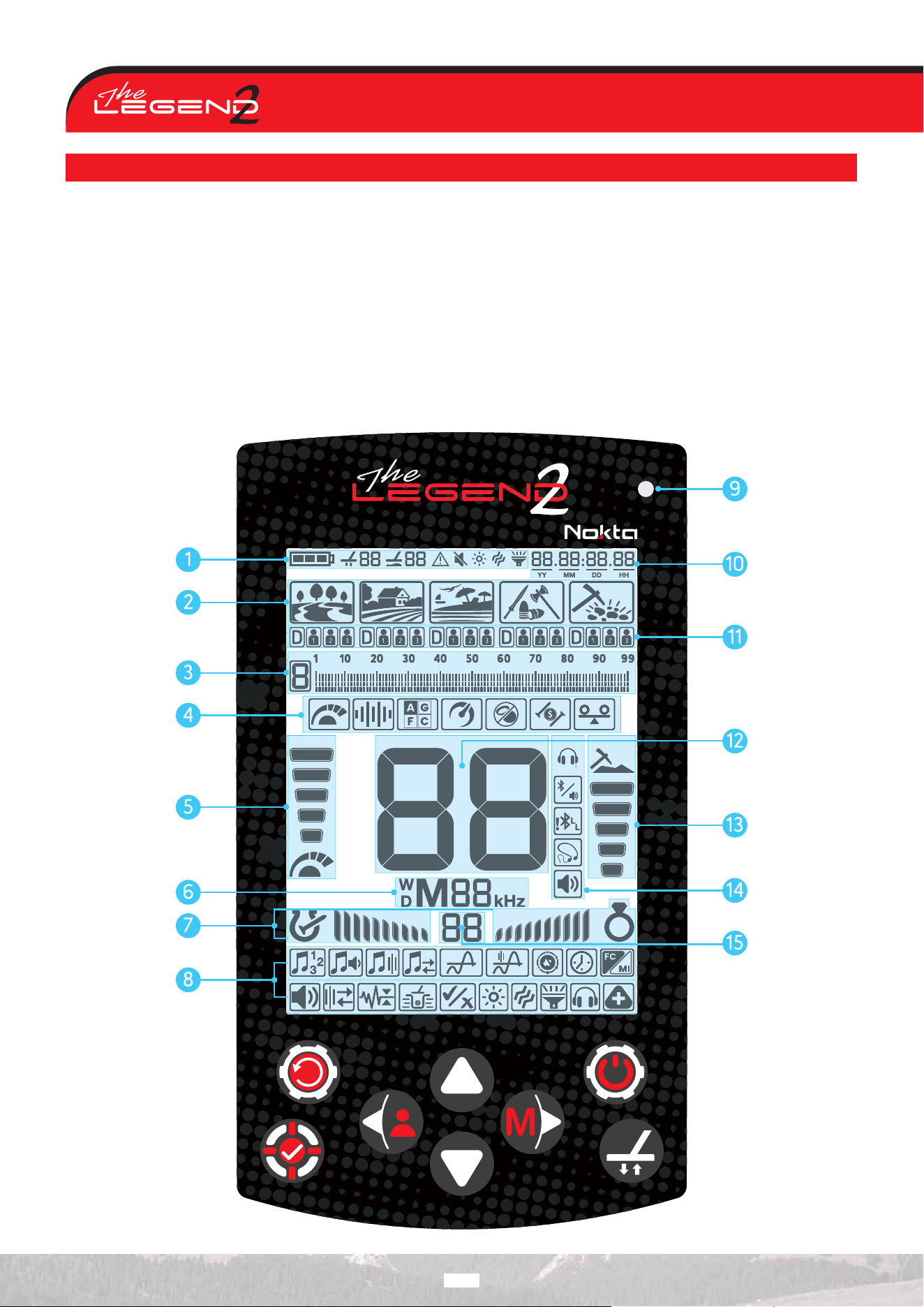
DISPLAY
1. Info Bar
2. Search Modes
3. Target ID Scale and Discrimination
Pattern
4. Quick Settings
5. Sensitivity Indicator
6. Operating Frequency
7. FerroCheck™ Bar
8. Settings
9. Charging LED
10. Clock and Usage Duration
11. User Profiles
12. Target ID
13. Depth Indicator
14. Audio Options
15. Auxiliary Indicator
8
BATTERY INFORMATION
The LEGEND 2 has an internal 6700 mAh Lithium-ion battery.
Battery runtime varies between 8-20 hours. Factors such
as operating frequency, usage of speaker or wired/wireless
headphones, display backlight, LED flashlight etc. will aect
battery runtime.
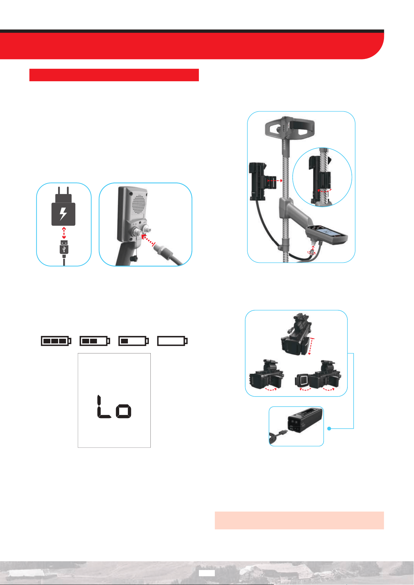
Charging
Charge The LEGEND 2 before initial use. Charging an empty
battery will take approximately 5-6 hours.
To charge the battery, insert one of the ends of the cable supplied
with the device to the wired headphones / charger input socket
and the other end to the charging adapter.
Use a standard 5V 2A (minimum) USB power adapter to charge
the device. Charging via a PC USB port may take longer.
Low Battery Level
The battery icon on the display indicates the battery level. As the
charge decreases, the bars inside the icon decrease accordingly.
When the battery is depleted, ‘Lo’ appears on the display and the
device powers o.
BATTERY WARNINGS
Do not expose the device to extreme temperatures (for example a
car’s trunk or glove compartment).
Do not charge the battery in temperatures over 35° C (95° F) or
below 0° C ( 32° F).
The LEGEND 2 battery can only be replaced by Nokta Detectors
or its authorized service centers.
WATERPROOF REPLACEABLE SPARE BATTERY
This optional battery, sold separately, can replace the internal Li-
Ion battery when it is depleted and you are unable to recharge it.
You can attach the spare battery easily as shown in the picture.
When you are using the spare battery, you cannot plug any wired
headphones to the device.
You can charge the spare battery easily using the charger it
comes with.
Operating with a Powerbank
You can also power and charge the battery with a powerbank. To
do this, just insert one of the ends of the cable supplied with the
charger to the wired headphones / charger input socket and the
other end to the powerbank. Please note that you will not be able
to attach wired headphones to the device when a powerbank is
attached to the device.
IMPORTANT! Do NOT use the detector underwater while
connected to a powerbank.
19
1
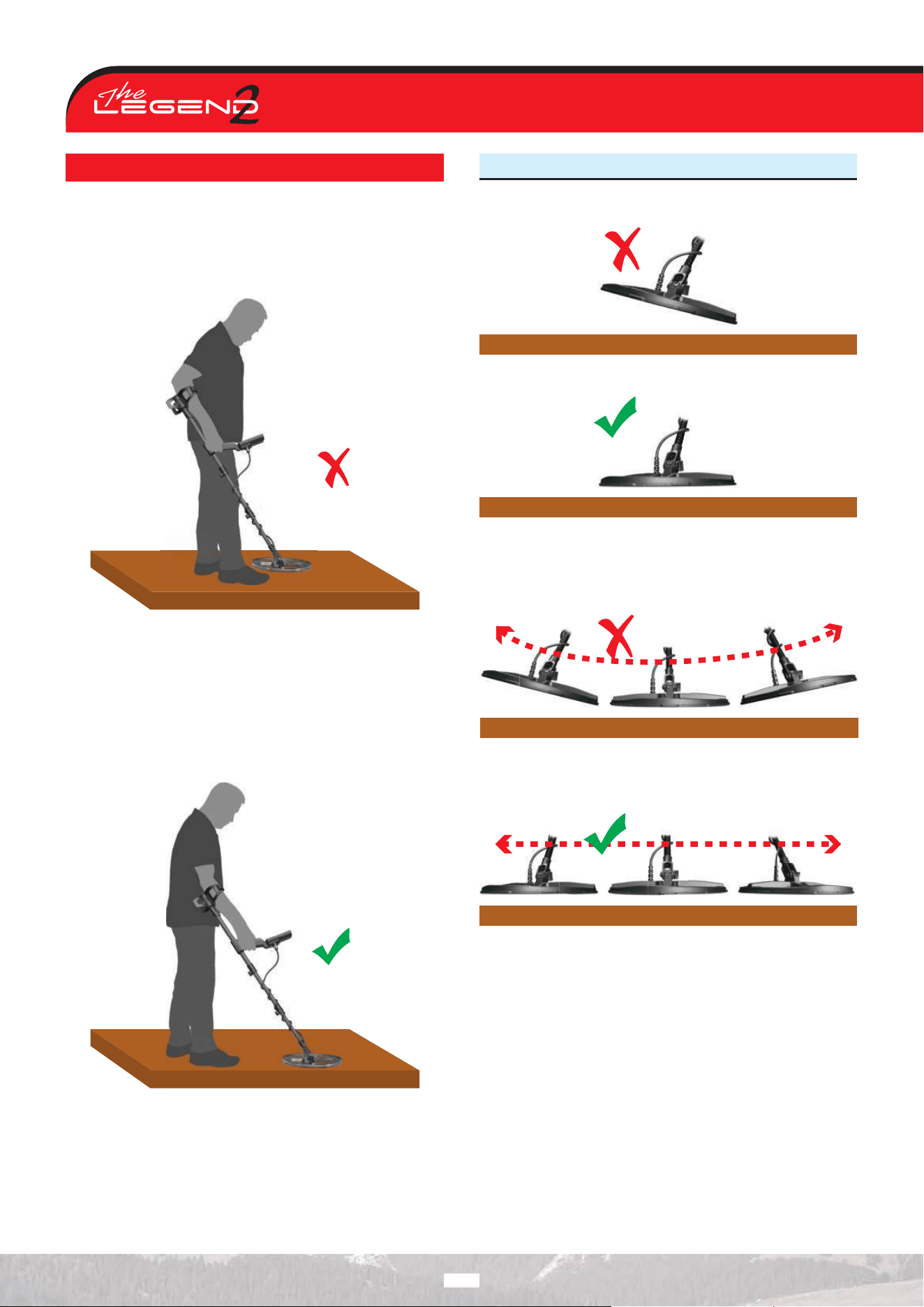
CORRECT USE
Shaft height is wrong
Adjust the shaft to your height to ensure comfortable use and
reduce fatigue during searching.
While detecting, the device may detect false signals from metal
objects you carry or from shoes containing metal.
Shaft height is correct
Adjust the height of the shaft so that you are standing in an
upright position, your arm is relaxed and the search coil is
approximately 5 cm (~2’’) above the ground.
While detecting, the device will not detect false signals from metal
objects you carry or from shoes containing metal.
CORRECT WAY OF SWEEPING
Wrong search coil angle
Correct search coil angle
Incorrect way of sweeping
It is important to keep the search coil parallel to the ground in
order to get accurate results.
Correct way of sweeping
The search coil must be parallel to the ground at all times.
10
1
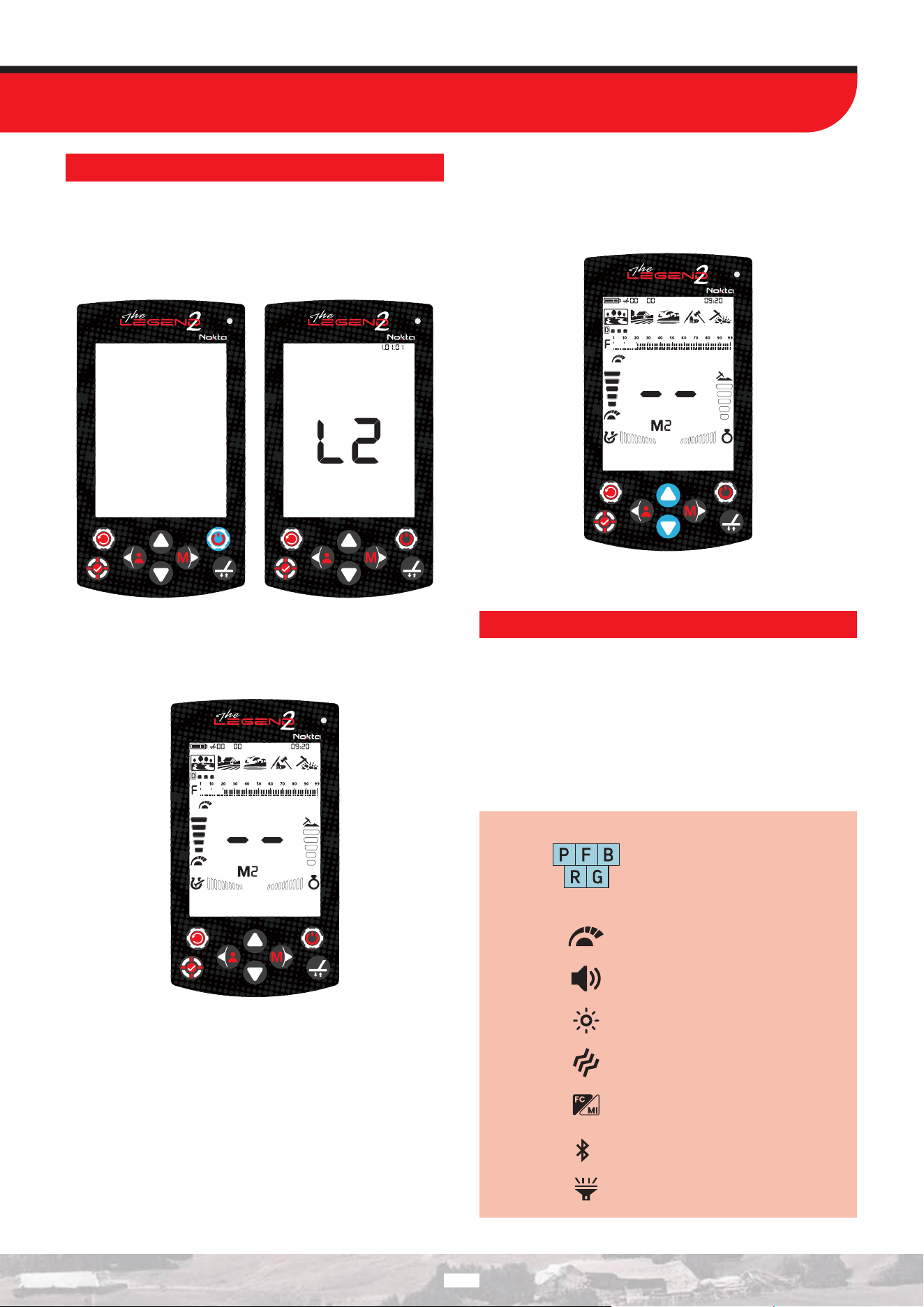
QUICK GUIDE
1. Assemble the device as per the instructions on page 3-6.
2. Press and hold the Power / Settings button for 2 seconds to
turn on the device. The loading message ‘L2’ will appear on the
screen, and the software version will be displayed in the upper-
right corner.
3. When the device is turned on, it will start in the Park mode and
in Multi frequency. You can change the mode based on ground
conditions. You can find more details on search modes and
frequencies further in this manual.
4. You can increase the selected quick setting, which is the
sensitivity setting, if needed. Increasing the sensitivity will oer
you greater depth. However, if the surroundings or the ground
cause excessive noise in the device, you need to lower the
sensitivity setting.
5. You can start detecting!
COMMON AND MODE-BASED SETTINGS
Certain settings are common to all modes; changes in these
settings will take eect in all modes.
Most of the settings are mode based and they only aect the
mode currently selected; changes made in one mode do not aect
the others.
Common settings and mode-based settings are marked as below
throughout the manual:
Park Field Beach
Relic
Gold
Common Settings
Sensitivity
Volume
Backlight
Vibration
FerroCheck™ / Mineralization Indicator
Bluetooth
®
LED Flashlight
11
1
FieldPark
Relic
Beach
Gold
Mode-Based Settings
.Ground Balance
Custom Discrimination Mode
Frequency
Recovery Speed
Bottle Cap Rejection /
Iron Rejection in Relic Mode
Iron Filter
Stability in Beach Mode
Frequency Shift
Ground Suppressor
Deep Target Identification
Number of Tones
Tone Volume
Tone Frequency
Tone Break
Threshold Level
Threshold Frequency
Audio Gain
Notch (Accepting and Rejecting IDs)
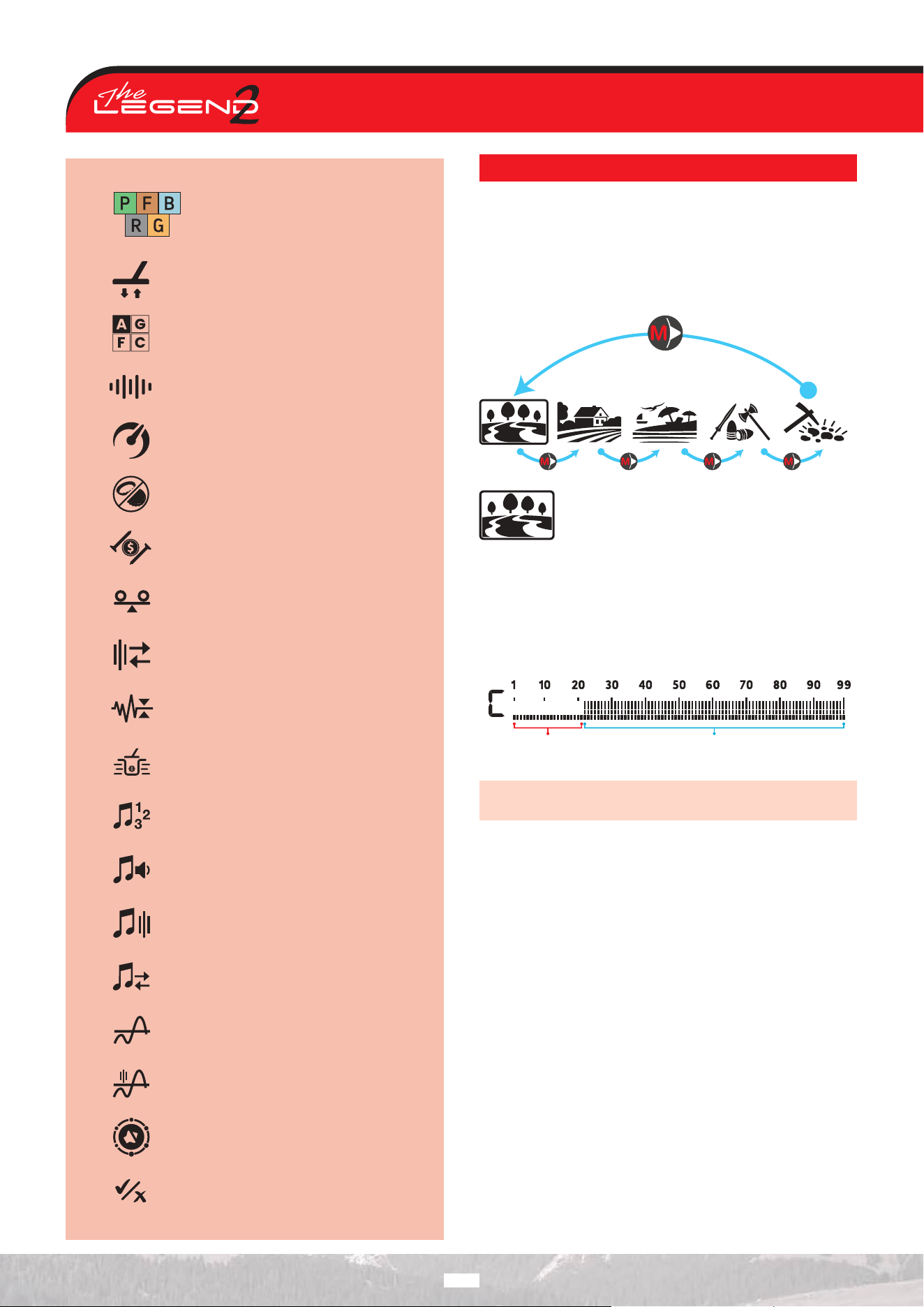
SEARCH MODES
The LEGEND 2 has 5 search modes designed for dierent terrains
and targets.
Navigating Through Search Modes
During the search, you can switch between modes on the main
screen using the Right button. The selected mode will be shown
within a frame.
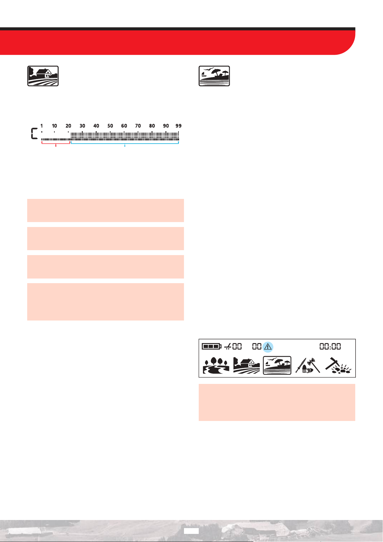
PARK
Designed for coin and jewelry hunting in urban
areas and parks where there are lots of modern
trash (aluminum foil, pull-tabs, bottle caps etc.)
present.
This mode is optimized for detecting medium and large coins and
jewelry. In the factory default setting, the custom discrimination
pattern excludes many targets, such as iron and aluminum foil.
Target IDs on the ID scale, including 21, are set to “o” to allow
searching without detecting these targets.
Rejected
IDs 1-21
Accepted
IDs 22-99
Aluminum foil typically generates a Target ID of 21. However,
depending on the shape, its ID can go up to 34.
All single frequencies as well as Multi frequency can be used in
this mode. Based on target type, you can choose the frequency
you want. Multi frequency in Park mode will allow for maximum
depth and separation. Thus, a slight noise can be experienced.
The Park mode is set to Recovery Speed 5 and 2 tones by default.
You can change the Recovery Speed as well as the number of
tones manually if needed.
The FerroCheck™ bar on the screen shows the ferrous/non-
ferrous ratio of the target and thus plays an important role in
identifying trash metals. Therefore, when a target is detected
while in Park mode, the FerroCheck™ bar should be observed in
addition to the Target ID.
12
1
FIELD
Recommended for coin and relic hunting in pasture
and cropped/plowed fields.
In these areas, iron-containing debris and coke fragments are
commonly found. To make it easier to detect coins and relics among
such debris, the Target ID scale in the custom discrimination
pattern is set to “o,” including 21, in the factory default settings.
Rejected
IDs 1-21
Accepted
IDs 22-99
In this mode, all single and multi frequencies operate. When Multi
frequency is selected, the device provides maximum depth and
discrimination capability. The Field mode comes from the factory
preset with a Detection Speed of 5 and a Target Tone Count of 2.
In Field mode, the first tone break point is 21 for all tone
options. In Park mode, the first tone break point is 20 for all
tone options.
The ID resolution of IDs 21-25 is dierent in Park versus the
Field mode. You may get a dierent ID in each mode for targets
that fall within this ID range.
Park and Field modes oer 3 dierent Multi frequencies as
Multi-1 (M1), Multi-2 (M2) and Multi-3 (M3). For details, please
refer to the Frequency section.
In Park and Field mode, dierent algorithms are used. On trashy
sites, M3 Multi-Frequency is recommended. When a target is
isolated underground, the ID will be the same in both modes.
However, if the target is next to trash, such as aluminum foil,
Multi 3 in Park mode will provide a more accurate ID.
BEACH
This mode is optimized for use on dry or wet beach
sand and for underwater use up to 5 m (16 ft).
Salt in beach sand and seawater makes the ground and water
highly conductive, generating noise and false signals. Single-
frequency detectors cannot operate eectively in these conditions,
while multi frequency detectors reduce noise and provide
maximum performance.
For these reasons, single frequencies cannot be used in the Beach
mode. When Beach mode is selected, the device automatically
switches to Multi frequency and single frequencies cannot be
selected. In this mode only, the Multi frequency has 2 options:
Wet sand/underwater (MW) or dry sand with very low salinity
(MD). When you change the frequency in Beach mode, you switch
between MW and MD.
If the sand you are detecting on is dry but has high salinity, use
the MW option. To determine salinity, move the search coil over
the sand in All Metal Discrimination Pattern (see Discrimination
Patterns) and check the ID of the sand. If the ID is higher than 4,
select MW instead of MD. You can also enable the mineralization
indicator to measure the salinity of the search area.
The ground balance and ID stability has been optimized for
dierent conditions and will vary for each option. In wet beach
sand, MW Multi frequency will generate accurate IDs but if you
switch to MD, the IDs may be wrong. Similarly, in dry sand with
low salinity, you can ground balance the detector in MD but if you
switch to MW, you may not be able to ground balance.
The Beach mode is set to Recovery Speed 6 and 2 tones by
default.
Black Sand
Some beaches are covered with black sand which contains
natural iron. These types of beaches make metal detection almost
impossible. Beach mode senses black sand automatically and
displays a warning icon on the top of the screen in the Info Bar.
IMPORTANT! After submerging the device underwater and
taking it out, water may enter the speaker cover, causing
mued audio. This is normal. Gently shake the device to
remove the water from the speaker cover, and the audio will
return to normal.
13
14
RELIC MODE
Very deep targets may have values close to the
surrounding soil and therefore may not be detected.
Relic mode allows you to detect targets at depths
that cannot be detected in other modes.
This mode resets the ground balance of the soil, allowing the
detector to detect deep coins and large masses. However, in this
mode, targets at the limit of detection may not provide an ID or
their IDs may be unstable.
Ground balancing is very important in Relic mode. To use Relic
mode most eciently, perform ground balancing first when the
mode is selected. In addition, a second ground balance feature is
available only in Relic mode. After performing the initial ground
balance, you can eliminate the eect of mineralized stones,
referred to as hot rocks, in the search area by using the second
ground balance on those stones.
Relic mode provides high performance on some beaches. As
with other terrains, it is recommended to use the All Metal
Discrimination Pattern when searching on the beach. Signals with
IDs 20 or 99 may originate from the beach in the area you are
detecting. By disabling these IDs using the ID Notch (ID Reject)
feature, Relic mode can be used on the beach without interference.
The Relic mode comes factory-set with a Detection Speed of 5
and a Target Tone Number of 1.
In this mode, tone options have been removed. The audio frequency
changes proportionally to the signal strength. Additionally, by
enabling the Iron Bias feature, you can distinguish iron-containing
targets that are close to the ground surface (see Iron Bias Feature
in Relic Mode).
GOLD
This mode is optimized for use on mineralized
goldfields.
In this mode, the factory setting includes an audible threshold
tone. The volume and the frequency of the audio alert emitted
when a target is detected, varies proportionally to the strength
of the target signal. Gold mode is ideal for detecting shallow and
small gold nuggets as well as deeper larger nuggets in mineralized
ground.
You can only use the higher single frequencies (20 kHz and 40
kHz) and the Multi frequency in this mode. In highly mineralized
ground, detectors receive a lot of false signals. In addition, there
are mineralized rocks -commonly referred to as hot rocks-
present in goldfields. Therefore, Multi frequency in this mode
oers convenient detection by minimizing the eects of these
mineralized rocks and ground.
The Gold mode is set to Recovery Speed 5 and 1 tone by default.
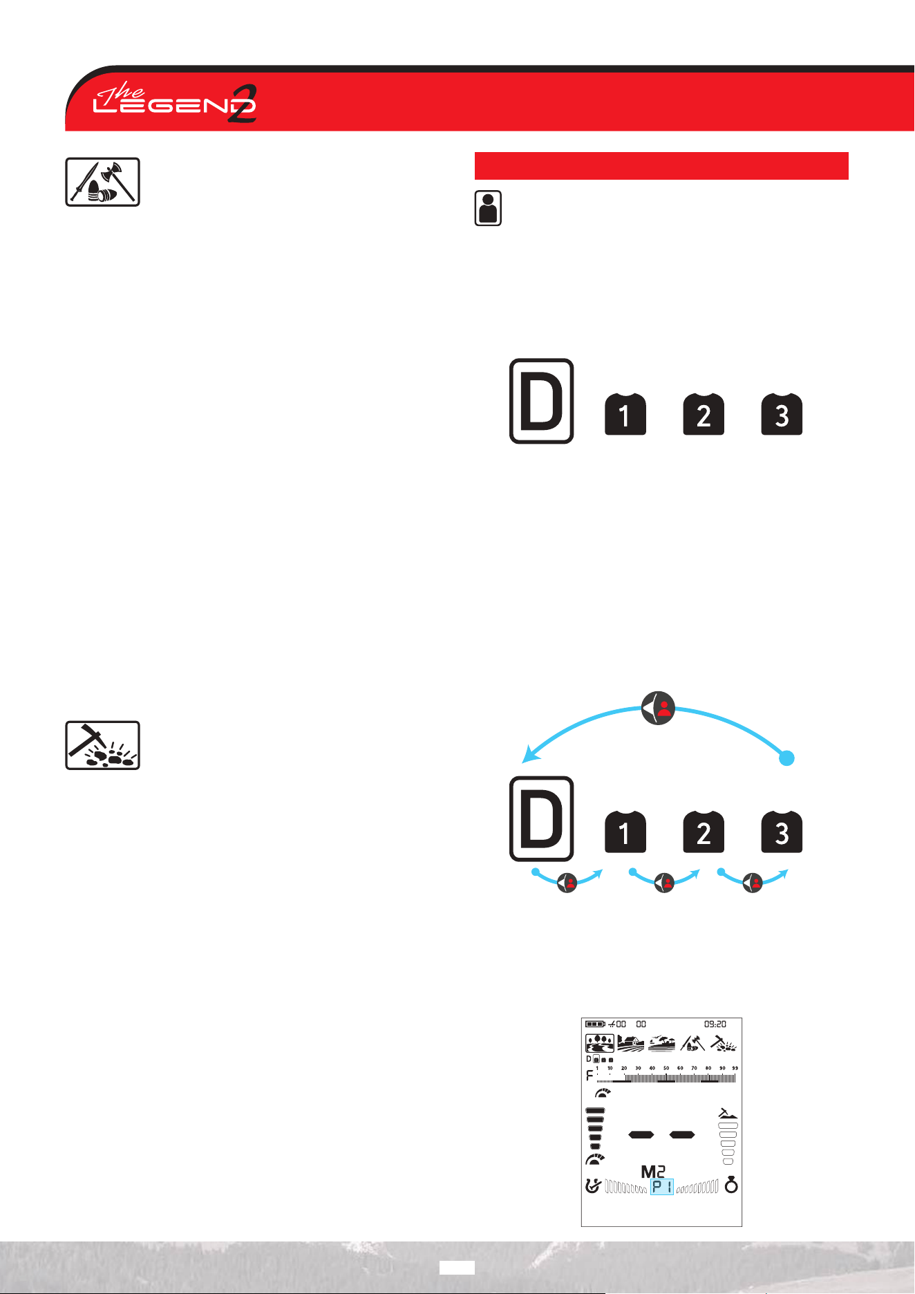
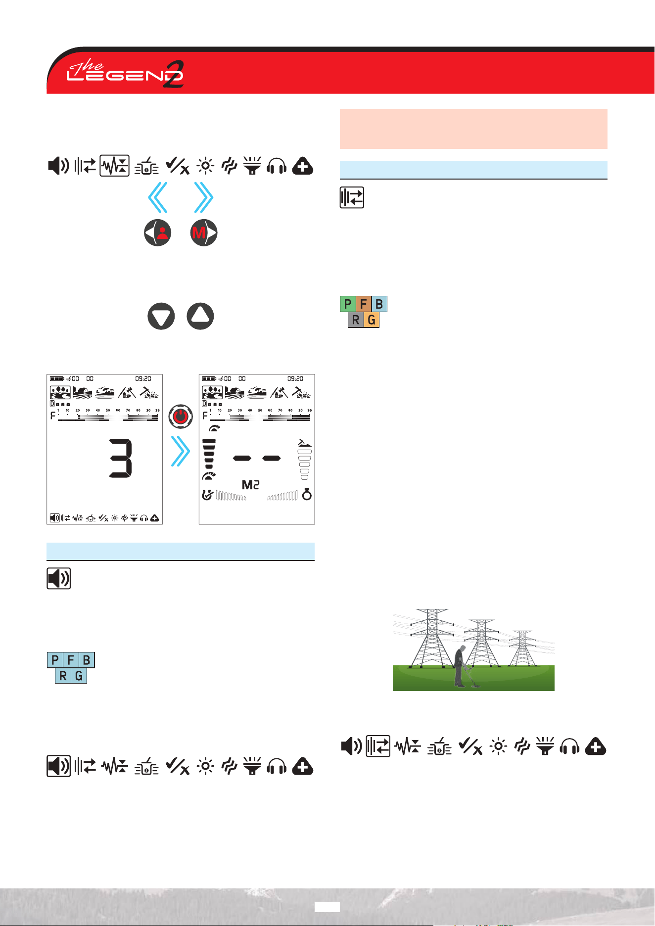
USER PROFILE
The LEGEND 2, oers the ability to save the settings you
make during searching to three dierent user profiles in
each mode. User profiles are available separately for each
search mode.
This is a great feature for users to preserve their optimized
settings. They can easily and quickly reuse the saved settings
later on.
User Profile Menu
The User Profiles of the search mode are displayed in the section
below the search mode.
All user profiles have the default settings of The LEGEND 2.
The Default (D) User Profile is preselected.
The D User Profile automatically saves the changes made by the
user. Since the automatic save feature is predefined, users cannot
manually save settings to this profile. If desired, the automatically
saved settings can be restored to factory defaults by performing
the “Clear Profile” operation.
Changing the Active User Profile
You can change the Active User Profile on the main screen by
pressing the Left button once. The Active User Profile is framed.
When the profile is changed, the selected profile information is
also displayed in the Auxiliary Indicator. This text is automatically
cleared after a short time.
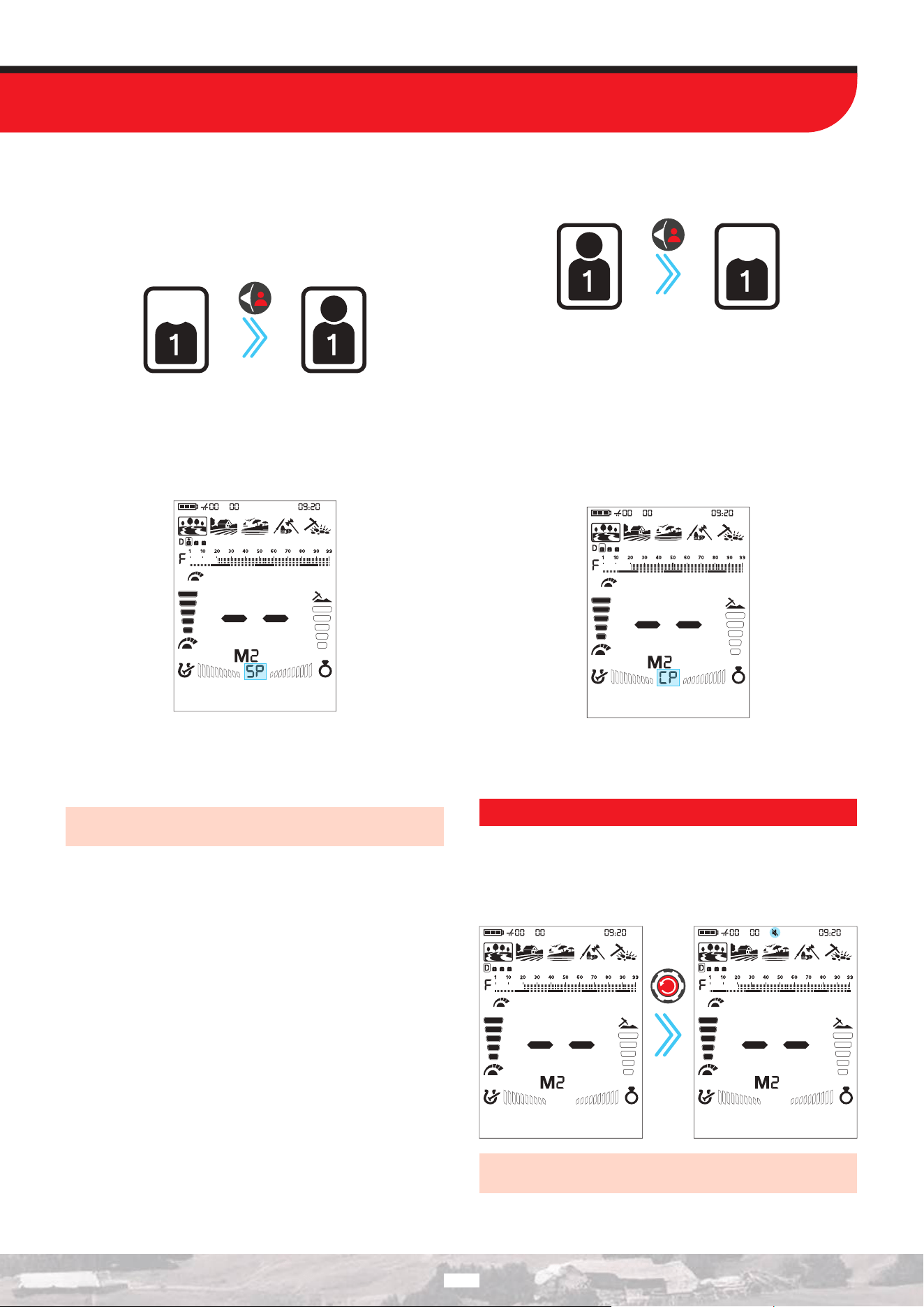
Saving a User Profile
If you want to preserve the settings you used after searching in
a specific area, you can save these settings to any User Profile.
1. After selecting a user profile in the User Profile menu, press and
hold the Left button for 2.5 seconds to save your settings to the
selected profile.
Press and hold
for 2.5 seconds
After the profile is saved, a head icon appears inside the User
Profile icon.
Along with the head icon, the text SP (Save Profile) is displayed in
the Auxiliary Indicator.
If the profile has been saved previously, the coil icon is already
displayed. When a new save is made over the existing profile,
the SP letters shown in the Auxiliary Indicator mean that the
overwrite has been completed successfully.
IMPORTANT! Common settings are saved automatically. User
Profiles save mode-specific preferences.
Clearing the User Profile
1. In the User Profile menu, use the Left button to select the saved
profile you want to clear.
Press and hold
for 5 seconds
2. Clear the user profile by pressing and holding the Left button
for 5 seconds. The head icon in the user profile will disappear.
To clear the profile, press and hold the Left directional button. After
2.5 seconds, the SP letters are displayed in the Auxiliary Indicator.
If you continue holding the button without releasing it, the CP
(Clear Profile) letters appear after 5 seconds. The disappearance
of the coil icon together with the CP letters indicate that the
profile has been erased. You can then release the button.
You can save your favorite settings for dierent targets and sites
with the user profile in each mode, allowing you to create a total
of 15 dierent detector setting sets across all modes.
MUTE FUNCTION
On the main screen, press and hold the Quick Settings button to
mute the device.
The mute icon will appear in the Info Bar at the top. You can turn
the sound on by pressing and holding the Quick Settings button.
Long
press
IMPORTANT! When the volume level is set to 0, the muted icon
is also displayed.
15
TARGET ID
Target ID is the number produced by the metal detector based on
the conductivity of the metals and gives an idea to the user about
what the target may be.
Target ID is shown with two digits on the display and ranges
between 01-99.
The LEGEND 2’s Target ID scale consists of 99 lines, each of
which represents 1 Target ID.
In addition to showing the Target ID in the middle of the screen,
the ID is also marked with a small cursor under the ID scale.
Ferrous range is 1-20.
Non-ferrous range is 21-99.
In some cases, the device may produce multiple IDs for the same
target. In other words, the IDs may be jumpy. This may result
from several factors. Target orientation, depth, purity of the metal,
corrosion, mineralization level of the soil etc. Even the direction of
the search coil swing may cause the device to generate multiple IDs.
In some cases, the device may fail to provide any ID. The device
needs to receive a strong and a clear signal from the target in
order to provide an ID. Therefore, it may not be able to provide
an ID for targets at fringe depths or smaller targets even if the
device detects them.
Keep in mind that Target IDs are “probable”, in other words,
estimated values and it would not be possible to know the
properties of a buried object exactly until it is dug out.
IDs of non-ferrous metals such as copper, silver, aluminum and
lead are high. Target ID range of gold is wide and may fall within
the same range of metal wastes such as iron, foil, screw caps, and
pull tabs. Therefore, if you are looking for gold targets, digging out
some trash metals is expected.
Coins searched throughout the world are made of dierent metals
and in dierent sizes in dierent geographical locations and
historical eras. Therefore, in order to learn the Target IDs of the
coins in a specific zone, it is suggested to perform a test with the
samples of such coins, if possible.
It may take some time and experience to make best use of the
Target ID feature in your search area. Dierent brands and models
of detectors produce dierent Target ID numbers.
IMPORTANT! Keep in mind, large targets will ID higher than
expected, even though they may be of lower conductance.
GROUND BALANCE
The LEGEND 2 is designed to work without ground
balancing on most terrains. However, for experienced users
and on highly mineralized grounds, ground balancing will bring
extra depth and stability to the device.
Ground balance can be performed in three ways with The LEGEND
2: Automatic, Manual and Tracking.
FieldPark
Relic
Beach
Gold
Ground balance only aects the mode currently
selected; changes made in one mode do not aect
the others.
The device can perform ground balance within the range of 00-99
in all modes and 00-20 in the Beach mode MW Multi frequency.
The ground balance must be performed separately for the Beach
MD Multi frequency and for Beach MW Multi frequency options.
The ground balance done in MD will not work for MW and vice
versa.
On The LEGEND 2 device, you can view both the ground
balance level and the level calculated based on real-time ground
measurement in the information area of the display. The real-
time ground balance measurement is shown to inform the user.
The ground balance level, on the other hand, indicates the ground
balance value at which the device is operating.
The ground
balance level
at which the
device is
operating
The real-time
ground
measurement
level shown for
informational
purposes
Automatic Ground Balance
Automatic ground balance is performed as follows in all search
modes:
1. Find a spot where there is no metal.
2. Hold the Ground Balance button down. The ground balance
icon will start blinking in the Info Bar at the top and the ground
balance value will be displayed in the middle of the screen. If
no ground balancing has been performed before, this value will
always be zero (0).
Hold
down
16
3. Start pumping the search coil up and down from
about 15-20 cm (~6’’- 8’’) above the ground down to 3
cm (~1’’) o the ground with smooth movements and
keeping it parallel to the ground.
4. Continue until the audio reduces in response to the ground.
Based on ground conditions, it usually takes about 2-4 pumps for
the ground balance to be completed.
5. The ground balance value is displayed on the screen in the
ID area and in the Info Bar. In order to ensure that the ground
balance is proper, ground balance at least 2-3 times and check
the ground balance values on the display. In general, the dierence
between the values shall not be higher than 1-2 numbers.
6. If you cannot ground balance, it means that either the ground
is too conductive or not mineralized or there is a target right
below the search coil. In such a case, retry ground balancing at a
dierent spot.
Manual Ground Balance
Allows you to manually modify the ground balance value. It is
not preferred mostly because it takes time. However, it is the
preferred option in cases where a successful ground balance
cannot be performed using other methods or minor corrections
are required to the automatic balance.
1. Find a clear spot without metals.
2. Press the Ground Balance button once. The device will switch
to the ground balance screen. The current ground balance value is
displayed in the center of the screen. If ground balance has not been
performed previously, this value will always be zero (0).
Press
once
3. You need to listen to the sounds coming from the
ground in order to perform manual ground balance.
Pump the search coil up and down from about 15-20
cm (~6’’- 8’’) above the ground down to 3 cm (~1’’) o
the ground with smooth movements and keeping it parallel to the
ground.
4. If you are getting a low tone while pumping the coil, it means
that that you should increase the ground balance value using the
Up button. On the other hand, if you are getting a high tone, you
should decrease the ground balance value using the Down button.
5. Continue the above process until the ground response is
eliminated.
6. Press the Ground Balance button once to exit.
The ground balance value may vary in single frequencies and
Multi frequency in certain soil types.
The sound may not be eliminated completely on certain
terrains. In this case, if the ground noise is minimized, it means
that the ground balance has been done.
Ground Tracking
The device tracks the changes in the ground during detection and
updates the ground balance automatically. Ground changes that
are not visible to the eye will aect the depth and discrimination
performance of the detector.
1. To activate ground tracking, press the Ground Balance button
once. The device will go into the ground balance screen.
2. Press the Pinpoint & Accept/Reject button once. In the Info Bar,
next to the ground balance icon, ground tracking icon will appear.
Press
once
Ground tracking is now active. Press the Ground Balance button
once to go back to the main screen.
When the Ground Tracking feature is activated, the ground balance
icon and the numerical values indicating the ground balance level
are removed from the information area. The Ground Tracking
icon is displayed, and in the section showing real-time ground
measurements, the ground balance level calculated by the Ground
Tracking feature and at which the device is operating is shown.
The device updates the ground balance automatically as long as
the search coil is swung over the ground.
Tracking is suitable for use in areas where dierent soil structures
are present within the same land or in fields where mineralized
rocks are scattered widely apart. If you use ground tracking in
areas where hot rocks are intensely present, the device may not
be able to eliminate these highly mineralized rocks or you may
miss the smaller or deeper metals.
When the Tracking feature is activated, the ground balance
level flashes on the screen. In Relic mode, when the Ground
Balance 2 is activated while the tracking feature is on, the
ground balance level will be shown steady to avoid confusion.
17
Second Ground Balance Feature in Relic Mode
Due to its configuration, Relic mode may cause the device to
give false signals to ground changes and mineralized/hot rocks.
This may cause discomfort to the user during detection. Relic
mode oers users a 2nd Ground Balance feature to overcome
mineralized/hot rocks, red bricks and other ground changes in
the surrounding environment that have dierent properties than
the soil that’s been ground balanced. With the second ground
balance, depending on the properties of the hot rock or brick, in
some cases, complete silence can be achieved over these falsing
targets. In other cases, a broken signal may be heard. Broken
sounds indicate that the detected target is a mineralized/hot rock.
To use this feature:
1. Press the Ground Balance button to access the setting.
2. Activate the 2nd Ground Balance feature by pressing the Quick
Settings button. When the 2nd Ground Balance is activated, the
number “2” appears on the screen above the letters Gb.
3. You can perform the 2nd Ground Balance by pressing and
holding the Pinpoint & Accept/Reject button.
When Relic mode is selected, 1st and 2nd Ground Balancing can
only be performed automatically. Manual ground balancing is not
possible.
4. You can switch back from the 2nd Ground Balance to the 1st
Ground Balance by pressing the Quick Settings button again.
Resetting the 1st and 2nd Ground Balance Settings in the Relic
Mode
While Relic mode is selected, the Ground Balance value is reset
by entering the ground balance menu and long pressing the Up
button. When the button is held down, the animation is shown on
the screen. To reset the 2nd Ground Balance value, first activate
the 2nd Ground Balance. Reset the 2nd Ground Balance value by
pressing the Up button again.
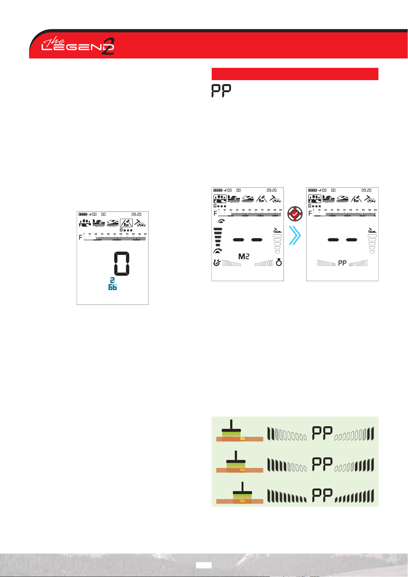
PINPOINT
Pinpoint is to find the center or the exact location of a
detected target.
The LEGEND 2 is a motion detector. In other words, you are
required to move the search coil over the target or the target over
the search coil in order for the device to detect the target. The
pinpoint mode is a non-motion mode. The device continues to give
a signal when the search coil is kept stationary over the target.
When the Pinpoint & Accept/Reject button is pressed, unused
icons are cleared from the screen. The pinpoint icon and the
FerroCheck™ bars are displayed empty.
In Pinpoint mode, the device continues to provide Target ID and
perform metal discrimination.
Press
once
To perform pinpoint:
1. After a target is detected, move the search coil aside where
there is no target response and push the Pinpoint & Accept/
Reject button.
2. Bring the search coil closer to the target slowly and parallel to
the ground.
3. Signal sound becomes stronger and changes in pitch while
getting closer to the target center and the bars in the FerroCheck™
start filling up from the outside to the inside.
4. Mark the position which provides the loudest sound using a
tool or your foot.
5. Repeat the above procedure by changing your direction 90°.
Actions to be performed from a couple of dierent directions
will narrow the target area and provide you with the most exact
details of the target location.
18
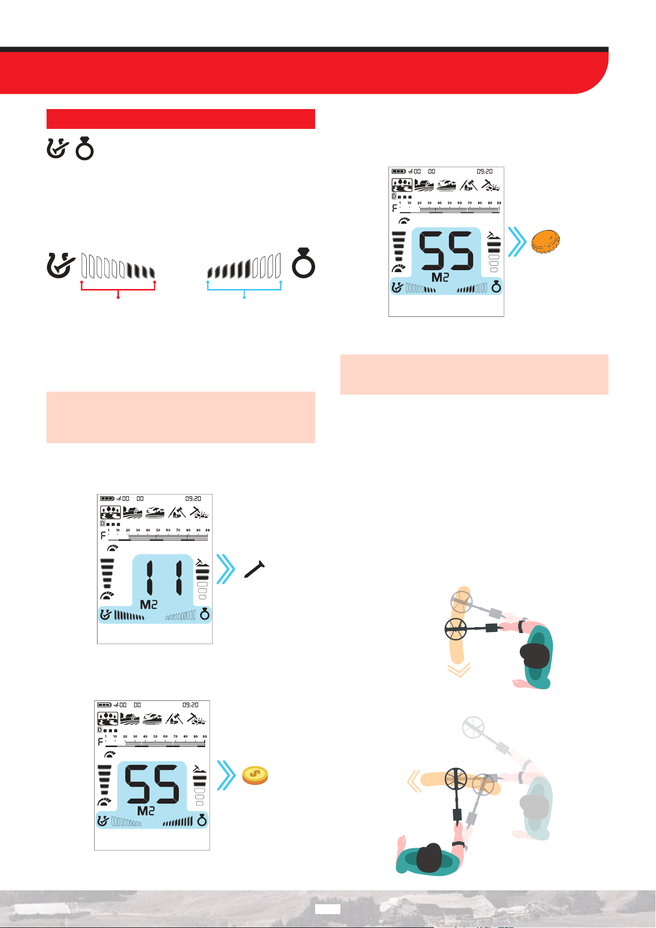
FERROCHECK™
The Target ID sometimes is not sucient.
FerroCheck™ shows the ferrous/non-ferrous ratio of
targets graphically on the screen.
The FerroCheck™ feature is a proprietary technology developed
by Nokta and is also available on The LEGEND device. It
graphically presents the Ferrous / Non-Ferrous ratio contained in
the target signal, enabling users to perform more accurate target
discrimination.
Ferrous ratio Non-ferrous ratio
Targets such as large iron, rusted nails, bottle caps contain both
ferrous and non-ferrous signals and these types of targets cannot
be discriminated by Target ID and audio response only. These
types of targets may generate a non-ferrous audio response as
well as a Target ID.
IMPORTANT! Until you get experienced with this feature, it is
recommended to dig out all targets. By comparing the targets
with the FerroCheck™ graphs, users can use this feature more
productively to identify targets.
Ferrous Target
Targets with ferrous signal only will be identified as 100% ferrous
both in Target ID and FerroCheck™ as shown below:
True Non-Ferrous Target
Targets with non-ferrous signal only will be identified as 100%
non-ferrous both in Target ID and FerroCheck™ as shown below:
False Non-Ferrous Target
When targets such as bottle caps generate a non-ferrous Target
ID, the FerroCheck™ feature identifies them as alloy with ferrous
(iron) content, as shown below.
The target generates a non-ferrous ID. However, it has both
ferrous and non-ferrous signal.
IMPORTANT! For the FerroCheck™ feature to work, the
detector must receive a strong signal. Therefore, FerroCheck™
is designed to work with shallower targets.
Correct Usage of the FerroCheck™
The accuracy of the FerroCheck™ feature is directly related to
correct usage. Therefore, once you detect a target, if you want
to check whether the target is ferrous or non-ferrous with the
FerroCheck™, please pay close attention to the instructions below:
1. You MUST sweep the coil with a large angle over the target and
make wide scans. Make sure that the search coil leaves the signal
completely during the sweeps.
2. You must go around the target and swing the coil over it from
dierent angles, with long sweeps again.
3. The ferrous side does not need to fill up completely. More than 2
bars is enough to identify a target as an alloy containing iron (not a
true non-ferrous target).
19
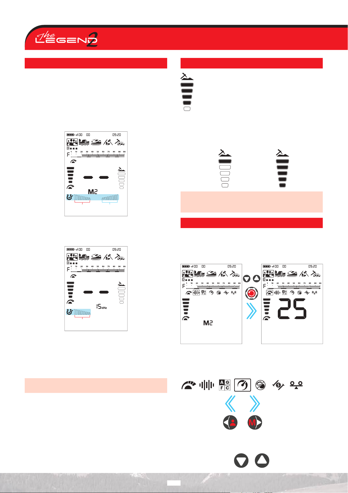
MINERALIZATION INDICATOR
Ground Mineralization refers to the naturally occurring minerals
in the ground that aect a metal detector’s performance. For
metal detectors, ground mineralization is caused by iron particles
present in the soil and by salt found in environments such as wet
sand. These factors cause the ground to be either magnetic or
conductive. Both produce false signals that mask targets.
Left side of the mineralization bar shows iron particle mineralization
and the right side shows mineralization due to salt.
Iron
Mineralization
Salt
Mineralization
Salt mineralization operates only in Multi frequency; therefore,
the mineralization indicator is updated according to the selected
frequency.
Iron
Mineralization
In single frequency, only the iron mineralization works. In Multi
frequency, both the iron and salt mineralization indicators work.
The selection of whether FerroCheck™ or the Mineralization
indicator will be displayed is explained in the FerroCheck™ /
Mineralization Option section.
The Salt Mineralization Indicator has been introduced to users
for the first time in the world by Nokta Engineering.
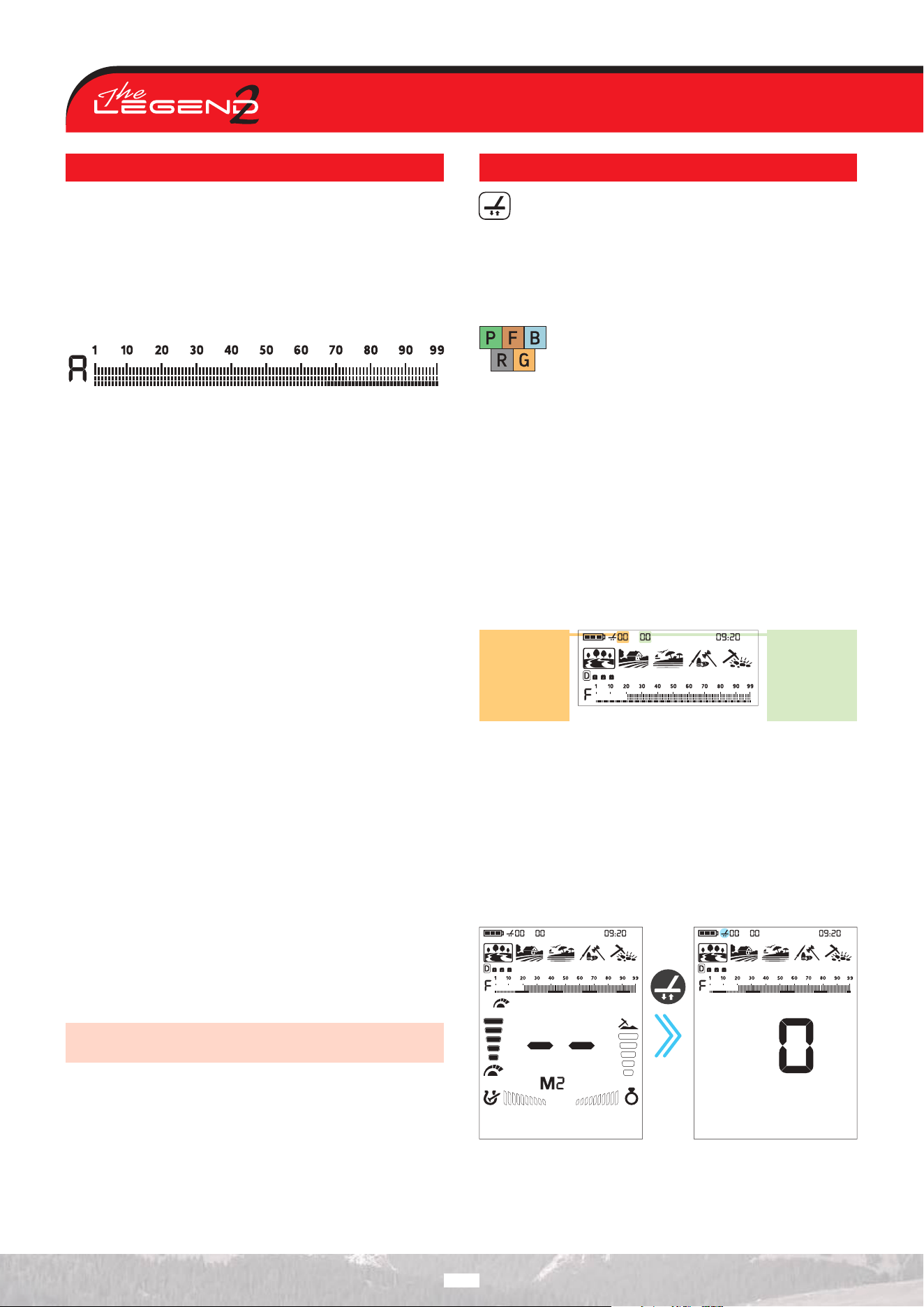
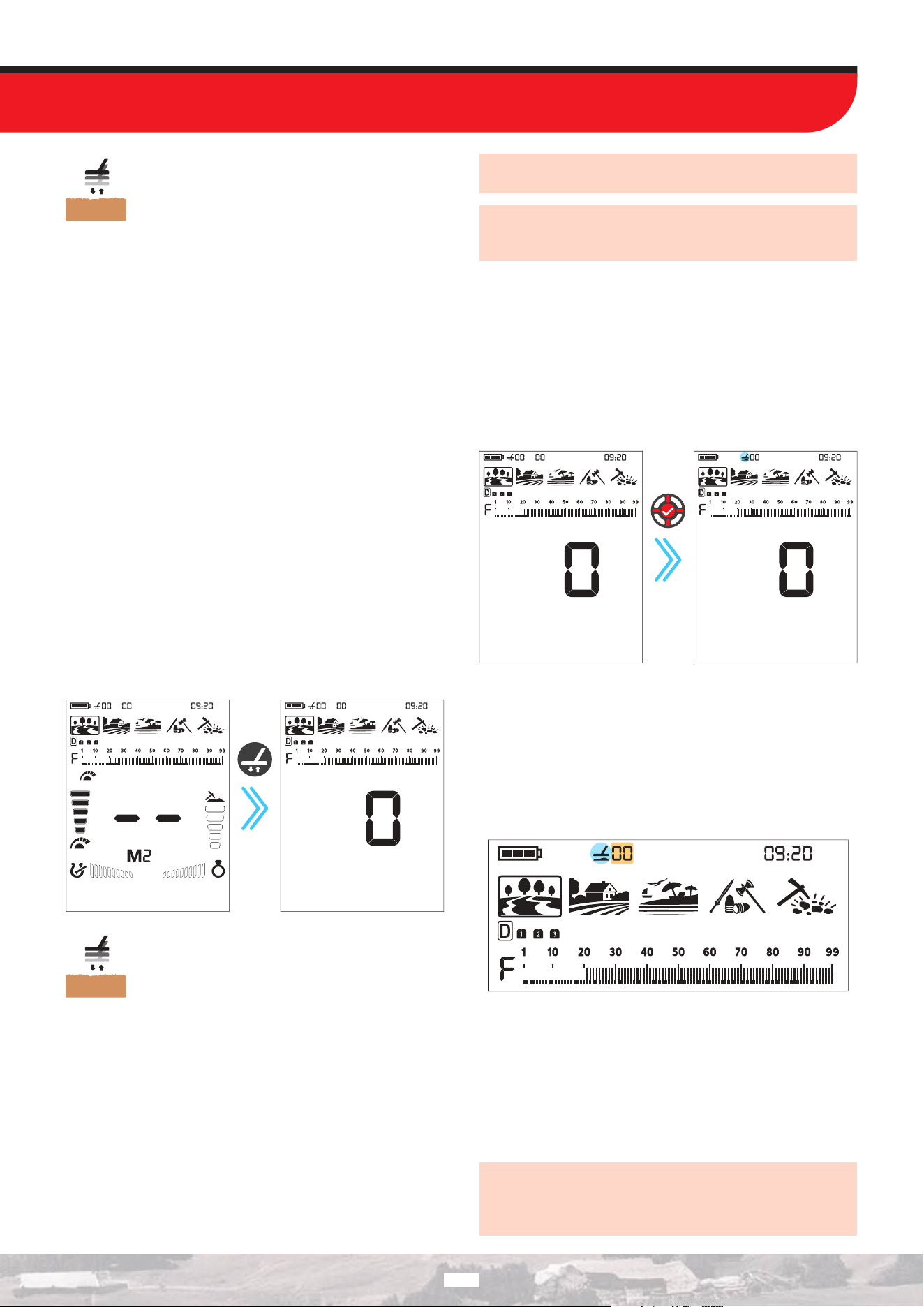
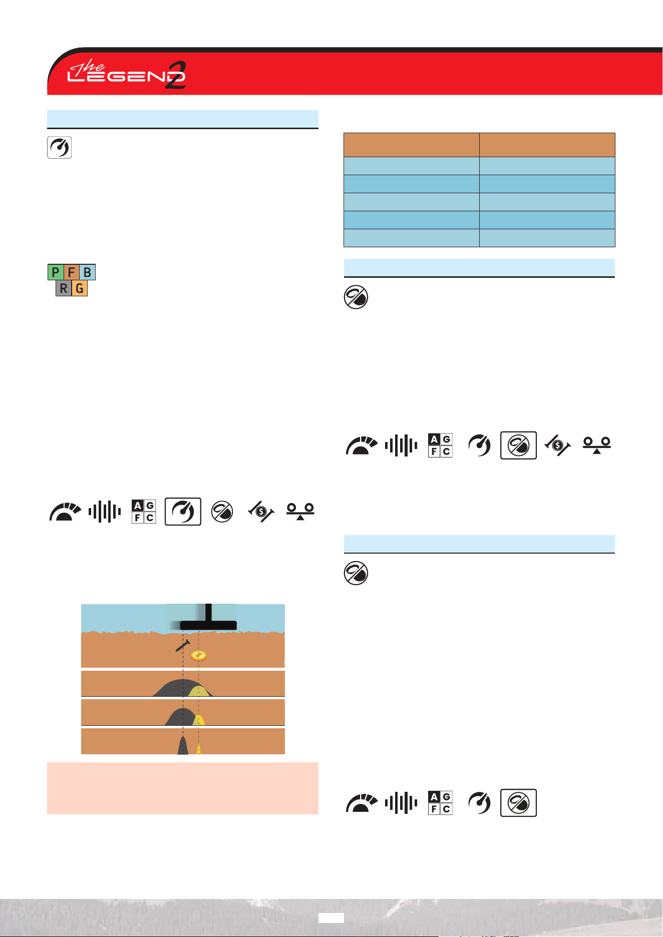
TARGET DEPTH
The device provides an estimated target depth according
to the signal strength during detection.
Depth Indicator: It shows the target’s proximity to the
surface in 5 levels during detection. As the target gets
closer, the levels decrease and vice versa.
Depth detection is adjusted presuming that the target is
a 2.5 cm (1’’) coin. Actual depth varies according to the size of the
target. For instance, the detector will indicate more depth for a
target smaller than a 2.5 cm (1’’) coin and less depth for a larger
target.
Shallow target Deep target
IMPORTANT! As the operating frequency of the device has a
direct impact on the device, the estimated depth may vary for
the same target during frequency changes.
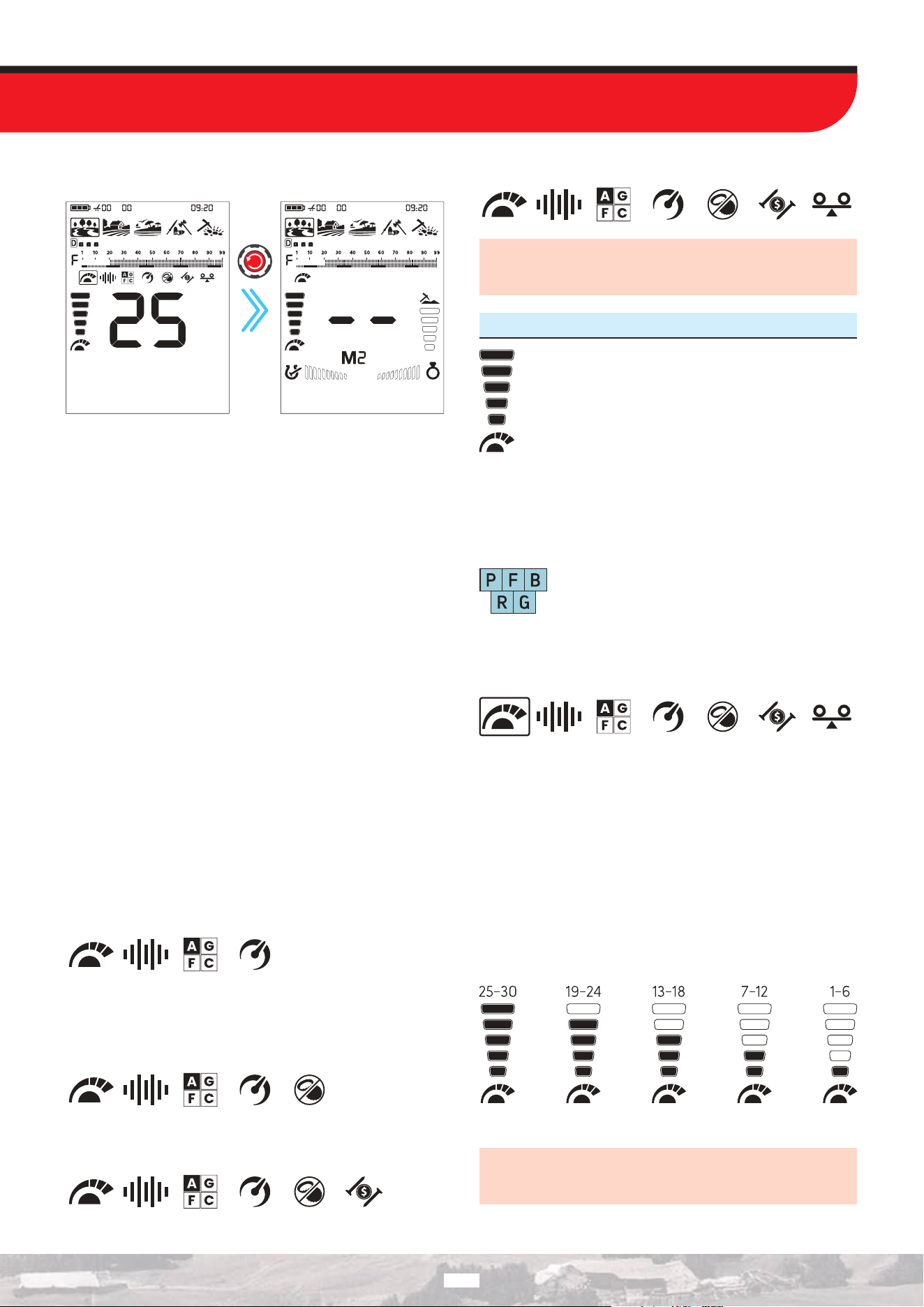
QUICK SETTINGS
To access the Quick Settings, press the Down button, Up button,
or Quick Settings button once. When pressed, the quick settings
located below the ID scale will appear, the icon of the selected
setting will be highlighted with a frame, and its value will be
displayed on the screen.
Press
once
Navigation Through Settings
You can navigate through the quick settings using the Right and
Left buttons. The selected quick setting will blink and be framed
for easier visibility.
Changing the Value of the Selected Feature
You can change their values using the Up and Down buttons.
20
Exiting the Menu
To exit the quick settings, press the Quick Settings button once.
Press
once
Changing the Selected Quick Setting on the Main Screen
After exiting the menu, the last selected quick setting remains
on the main screen. When the Quick Settings menu is not open,
you can change the value of the selected quick setting on the
main screen using the Up and Down buttons. The changed quick
setting will blink for easier visibility.
The Quick Settings menu has two dierent operating modes.
By factory default, when you exit the Quick Settings menu, the
last adjusted setting remains selected. If you want the selected
setting to always be Sensitivity, regardless of which setting was
adjusted last when exiting the Quick Settings menu, navigate to
the Sensitivity setting and press and hold the Pinpoint & Accept/
Reject button until the letters SS (Sensitivity Selected) appear in
the extra display area. The operating mode of the Quick Settings
menu is then updated so that it always selects the Sensitivity
setting when exiting the menu. This change is stored in the device’s
memory and remains active even after the device is powered o
and on again. If you want to revert the Quick Settings menu to the
factory default behavior—where the last adjusted setting remains
selected—navigate to the Sensitivity setting and press and hold
the Pinpoint / Confirm button until the letters LS (Last Selected)
appear in the extra display area.
The settings available in the Quick Settings menu are displayed
based on the selected mode, frequency, and other settings.
When single frequencies are selected, only the first four Quick
Settings options are displayed in the Quick Settings menu. Other
features are not shown, as they are exclusive to Multi frequency.
When the Relic search mode is selected, only the first five quick
settings are displayed in the quick settings menu. Since the Relic
mode operates only in Multi frequency, the frequency selection
option is skipped.
The other modes, except for the Relic search mode, have an iron
filter setting in their Multi frequency options.
The Stability setting exists only in Beach mode.
If no button is pressed after changing a quick setting with the
Up and Down buttons, the device will automatically exit the
Quick Settings and return to the main screen.
1. Sensitivity
Sensitivity is the depth setting of the device. It is also
used to eliminate the ambient electromagnetic signals
from the surrounding environment and noise signals
transmitted from ground.
Sensitivity consists of 30 levels and default setting is 25.
Sensitivity setting is a personal preference. However, It is important
to set the sensitivity to the highest level possible where no major
popping sounds are heard to avoid missing smaller and deeper
targets. For example; if the noise level is suitable for searching
and is the same at level 25 and 30, then 30 should be preferred.
Park Field Beach
Relic
Gold
Sensitivity is a common setting for all modes and
changes to this setting will aect them all.
Changing the Sensitivity
Open the Quick Settings. Use the Right and Left buttons to select
the Sensitivity feature.
The current Sensitivity value will be displayed on the screen.
You can increase or decrease it using the Up and Down buttons.
Each press adjusts the sensitivity step by step, while holding the
buttons changes it rapidly.
You can exit the menu by pressing the Quick Settings button.
The Sensitivity Indicator is located on the left side of the Target
ID. The indicator consists of 5 levels. Each level represents 6 units
of sensitivity.
The sensitivity values corresponding to each level on the Depth
Indicator are shown below:
The device always starts with the last adjusted sensitivity level.
IMPORTANT! To obtain maximum depth performance, to
eliminate the noise caused by electromagnetic interference,
try shifting the frequency first.
21
2. Frequency
The LEGEND 2 oers Multi frequency, where a wide
range of frequencies work simultaneously, as well as 5
single frequencies.
Changing the Frequency
Open the Quick Settings. Use the Right and Left buttons to select
the Frequency feature.
You can easily switch between frequencies at any time using the
Up and Down buttons.
You can exit the menu by pressing the Quick Settings button.
It is recommended to use Multi frequency in all modes. When Multi
frequency is selected the letter ‘’M’’ appears on the screen. When
a single frequency is selected, the frequency is shown numerically
on the screen.
The table shows the frequencies available in the search modes.
Frequency Operation By Mode
PARK
FIELD BEACH RELIC GOLD
Multi
4 kHz
10 kHz
15 kHz
20 kHz
40 kHz
FieldPark
Relic
Gold
BeachPark
Relic
Frequency only aects the mode currently selected;
changes made in one mode do not aect the
others.
Single Frequencies
Sometimes using single frequencies may provide an advantage
over Multi frequency. For example; if you are looking for larger
high conductive targets only, the 4 kHz may be a better choice.
Similarly, if you are looking for shallow, thin jewelry, 20 kHz and
40 kHz may provide better results.
In areas where there is electromagnetic interference, single
frequencies may be less noisy compared to Multi frequency.
However, they will be less sensitive to many targets at the same
time.
4 kHz will provide more depth specifically for larger silver coins
and relics compared to Multi and other frequencies but it will be
noisy in certain soil conditions.
Multi Frequency
Multi frequency which runs multiple frequencies simultaneously
gives the user the advantage of covering a broader range of
targets on all types of terrains.
Multi frequency, compared to single frequencies, typically provides
more accurate IDs at depth. In addition, it oers maximum depth
for a large range of metals with dierent sizes on wet salt beach
sand and underwater by minimizing ground noise.
Modes and Frequencies
Each search mode has been optimized with frequencies to oer
the best performance. For example, Park and Field mode works
in all single frequencies as well as Multi. On the other hand, the
Beach mode will only perform well in Multi frequency so single
frequencies cannot be selected in this mode. In addition, in the
Beach mode the Multi frequency has 2 options: Multi Wet (MW)
and Multi Dry (MD).
The Gold mode, on the other hand, is optimized to detect smaller
low conductive targets and that is why the lower single frequencies
(4 kHz, 10 kHz and 15 kHz) cannot be used in this mode.
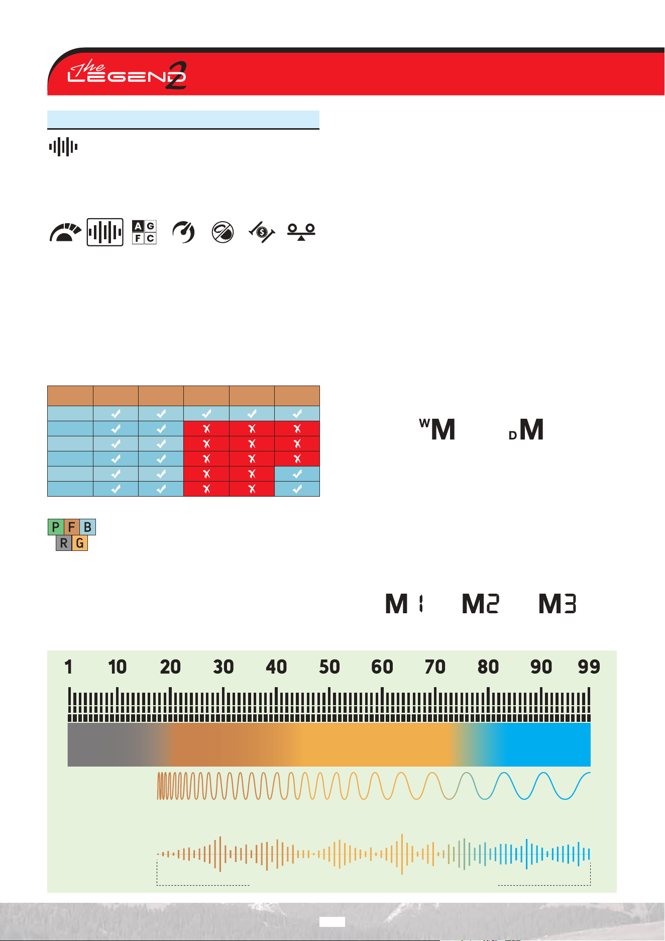
Unlike other modes, Park and Field mode oers three Multi
frequency options: Multi-1 (M1), Multi-2 (M2) and Multi-3 (M3). M1
is more sensitive to high conductors, while M2 provides better
detection of low conductors.
Multi-3 Frequency is ideal for damp, wet, and/or conductive soils.
It reduces the eect of moisture that can cause false signals in
the ground. It also weakens the responses of targets such as coke
and aluminum foil, which give a Target ID of 20–21.
Ferrous Targets
Nails, Iron…
Low Conductive Targets
Foil, Small Gold Jewelry,
Nickels, Coke…
Medium Conductive Targets
Coins, Large Jewelry,
Small Silver...
High Conductive Targets
Large Silver and
Copper Coins…
High Frequencies
provide better results
Low Frequencies
provide better results
Simultaneous Multi frequency provides better results for all targets
22
3. Discrimination Patterns
The LEGEND 2 oers advanced discrimination setting to
users for an easier operation. By Using the Discrimination
Mode feature, you can select one of 3 preset discrimination
models or 1 fully user-controlled model. In the Custom
discrimination pattern, each ID can be rejected or accepted by the
user.
The default discrimination pattern for Park, Field, and Beach
modes is “F” discrimination pattern which stands for (Ferrous O).
In Gold mode, the default discrimination pattern is “G” (Ground O).
In Relic mode, the default discrimination model is “A”, which is the
(All Metals) discrimination model.
FieldPark
Relic
Gold
BeachPark
Relic
The discrimination setting only aects the mode
currently selected; changes made in one mode do
not aect the others.
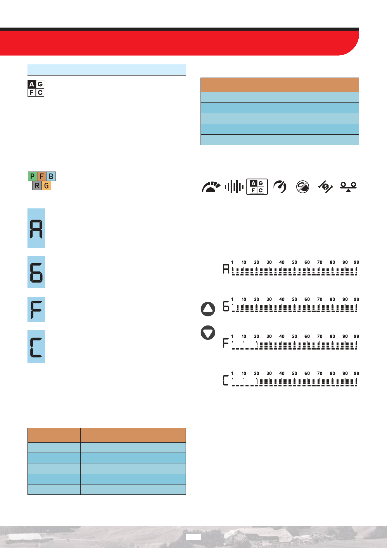
All Metal Discrimination Pattern
In this pattern all ID’s are accepted on the ID scale (1-99).
In other words, all the lines on the scale are visible and
no ID is rejected. The device will emit an audio response
for all metals as well as the ground and their IDs will be
displayed on the screen.
Ground O Discrimination Pattern
In this pattern, the device will not receive ground noise
and will not provide any audio or Target ID for it. Target
IDs 1-4 are turned o (rejected) and the rest are open
(accepted).
Ferrous O Discrimination Pattern
In this pattern, the device will not provide any audio or
Target ID for ferrous targets. Target IDs 1 - 20 are turned
o (rejected) and the rest are open (accepted).
Custom Discrimination Pattern
This pattern allows users to create their own
discrimination pattern according to the type of targets
they would like to accept and reject. Rejected IDs will
vary based on the search mode.
Accepting and rejecting IDs are also referred to as ‘’notching’’ or
to “notch”.
The default, accepted and rejected IDs in the Custom Discrimination
Pattern for each mode are shown in the table below:
Rejected And Accepted IDs In Modes’ Predefined Custom
Discrimination Patterns
Rejected IDs Accepted IDs
PARK
FIELD
BEACH
RELIC
GOLD
1-21 22-99
22-99
21-99
21-99
21-99
1-21
1-20
1-20
1-20
Search Mode
Default Discrimination Patterns by Mode
PARK
FIELD
BEACH
RELIC
GOLD
Discrimination Patterns
Ferrous O (F)
Ferrous O (F)
Ferrous O (F)
All Metal (A)
Ground O (G)
Search Mode
Changing the Discrimination Pattern
Open the Quick Settings. Use the Right and Left buttons to select
the Discrimination Mode feature.
You can easily switch between Discrimination Modes at any time
using the Up and Down buttons.
Each time you change the discrimination pattern, the selected
pattern is shown with a letter and a frame in the box on the left
side of the ID scale.
You can exit the menu by pressing the Quick Settings button.
With the notch feature, you can accept (turn on) and reject (turn
o) multiple IDs. The lines for the rejected IDs will be erased and
these IDs will be blanked out on the ID scale. The device will not
provide an audio response or Target IDs for these targets. The
use of the ID Accepting / Rejecting feature is explained in the ID
Accepting / Rejecting section.
23
4. Recovery Speed
The Recovery Speed setting adjusts the speed of target
response.
It allows for separation between multiple targets in close proximity.
Recovery Speed setting enables you to detect smaller targets
among trash or ferrous targets.
The LEGEND 2 Recovery Speed setting can be adjusted between 1
and 10 with 1 being the slowest and 10 being the fastest.
FieldPark
Relic
Gold
BeachPark
Relic
Recovery Speed setting only aects the mode
currently selected; changes made in one mode do
not aect the others.
When the Recovery Speed setting is set to a low number, the
ability of the device to detect targets in close proximity decreases
but its depth increases.
Similarly, a high Recovery Speed setting (for example 10) will
increase the ability of the device to detect targets in close
proximity but will decrease the depth.
It is recommended that you practice with dierent metals placed
close to each other before starting to use this setting.
Adjusting the Recovery Speed
1. Open the Quick Settings. Use the Right and Left buttons to
select the Recovery Speed feature. The current value will be
displayed on screen.
2. Change the value of the Recovery Speed using the Up and
Down buttons.
3. Press the Quick Settings button once to go back to the main
screen.
Low Recovery Speed
Medium Recovery Speed
High Recovery Speed
IMPORTANT! Increasing the Recovery Speed allows for a faster
sweep rate with less chance of missing targets. Increasing
Recovery Speed at the same sweep rate will help to eliminate
ground noise but it will decrease detection depth.
Default Recovery Speed Levels by Mode
Search Mode
PARK
FIELD
BEACH
RELIC
GOLD
5
5
6
5
5
Recovery Speed
5. Bottle Cap Rejection
Bottle caps are unwanted targets for detectorists and
they are mostly detected as non-ferrous targets by metal
detectors. With the Bottle Cap Rejection setting, you can
discriminate bottle caps as iron.
Bottle Cap Rejection setting can be set between 0 to 8 and the
default setting is 0. This setting work in Multi frequency only.
Adjusting the Bottle Cap Rejection
Open the Quick Settings. Use the Right and Left buttons to select
the Bottle Cap Rejection feature. The current Bottle Cap Rejection
value will be displayed on the screen.
You can change the Bottle Cap Rejection setting value between 1
and 8 using the Up and Down buttons. When set to 0, this feature
is o.
You can exit the menu by pressing the Quick Settings button.
5.1. Iron Rejection Feature in Relic Mode
Relic mode, like the Gold mode, produces signals for both
non-ferrous and ferrous targets by changing the frequency
of the sound according to the strength of the received
signal. In order to distinguish ferrous targets, especially those
closer to the surface, depending on the signal strength received
from the ferrous target, the device emits a lower tone than that of
the non-ferrous targets with the frequency varying according to
the strength of the signal.
You can adjust the Iron Rejection value between 0-5 and 0 is the
default value.
When the value is increased, the probability of emitting a ferrous
tone for deep non-ferrous targets increases.
Adjusting the Iron Rejection
In Relic mode, open the Quick Settings. Use the Right and Left
buttons to select the Bottle Cap/Iron Rejection feature. The
current Iron Rejection value will be displayed on the screen.
You can change the Iron Rejection setting value between 1 and 5
using the Up and Down buttons. When set to 0, this feature is o.
You can exit the menu by pressing the Quick Settings button.
24
6. Iron Filter
Iron filter allows desired non-ferrous targets in trashy
sites, previously masked by iron, to be detectable.
The Iron Filter setting operates only in Multi frequency and can be
adjusted between levels 1 and 9.
This setting is not available in Relic mode.
Level 9 will become handy when trying to discriminate some
unwanted mid-conductors such as shotgun cartridges as iron.
Lower Iron Filter setting will increase the probability of ferrous
targets to be classified as non-ferrous targets and vice versa.
Adjusting the Iron Filter
When the device is operating in Multi frequency mode, open the
Quick Settings. Use the Right and Left buttons to select the Iron
Filter feature. The current Iron Filter value will be displayed on
the screen.
You can change the Iron Filter setting value using the Up and
Down buttons.
You can exit the menu by pressing the Quick Settings button.
Default Iron Filter Levels By Mode
Search Mode
PARK
FIELD
BEACH
RELIC
GOLD
3
3
1
-
3
Iron Filter
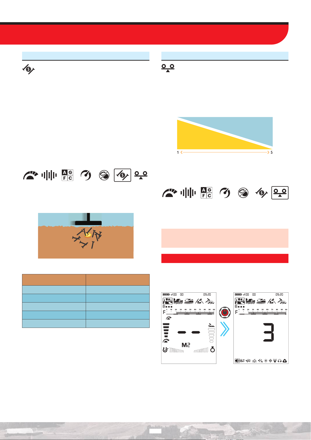
7. Stability in Beach Mode
With this setting, you can minimize the ground noise and
false signals on the beach for a more comfortable metal
detecting experience.
The stability can be set between 1 to 5. The default setting is 5.
Level 5 will oer maximum stability. As the stability is increased
though, the signal of lower conductors such as gold with 21 ID may
diminish and the chances of missing these metals will increase.
This setting has no eect on mid to high conductors.
Stability
Low conductive metals
Adjusting the Stability in Beach Mode
In Beach Mode, open the Quick Settings. Use the Right and Left
buttons to select the Stability feature. The current Stability value
will be displayed on the screen.
Use the Up and Down buttons to change the Stability setting
value.
Press the Quick Settings button to exit the menu.
IMPORTANT! In some environments, 4th level of the stability
setting may provide better stability than level 5. This is related
to the salinity of the water.
SETTINGS
To go into the settings menu, press the Power / Settings button
once. Once the button is pressed all the settings will be displayed
at the bottom of the screen. The selected setting will be shown
framed and its value will be displayed on screen.
Press
once
25
Navigation Through Settings
You can navigate through the settings using the Right and Left
buttons. The selected setting will blink for easier viewing.
Adjusting a Setting
You can adjust the value of a setting using the Up and Down
buttons.
Exiting the Settings Menu
Press the Power / Settings button once to exit the settings menu.
Press
once
1. Volume Level
This setting allows you to adjust the device’s overall
volume level.
Volume level setting consists of 10 levels and it is set to 7 by
default. When you turn o and on the device, it will start with the
last volume level you chose.
Park Field Beach
Relic
Gold
This setting is common to all modes; changes will
take eect in all modes.
Adjusting the Volume
1. Press the Power / Settings button once. Select Volume using
the Right and Left buttons. The current value will be displayed
on screen.
2. Change the volume level using the Up and Down buttons.
3. Press the Power / Settings button once to go back to the main
screen.
Because the volume level aects power consumption, we
recommend you not to increase it more than necessary.
IMPORTANT! When you change the volume of the device with
this setting, the volume of the metal zones adjusted by the
Tone Volume setting will also change proportionally.
2. Frequency Shift
It is used to eliminate the electromagnetic interference
that the device receives from another detector which
operates in the same frequency range nearby or from the
surroundings (high voltage power lines, cellular base stations,
wireless radios and other electromagnetic devices).
There are 19 channels available for all frequencies including Multi
frequency. The default channel is 10.
FieldPark
Relic
Gold
BeachPark
Relic
Frequency Shift only aects the mode and
frequency currently selected; changes made in one
mode does not aect the other modes or
frequencies.
If too much noise is received when the search coil is lifted in the
air, this may be caused by the local electromagnetic signals or
high sensitivity level.
To achieve maximum depth performance and reduce noise caused
by electromagnetic interference, try shifting the frequency before
lowering the sensitivity.
Detectors may become noisy due to electrical interference and
may exhibit erratic behavior such as loss of depth or unstable
Target ID. The Frequency Shift setting allows you to slightly shift
the detector transmit frequency to eliminate unwanted noise.
Frequency Shift can be done in 2 ways in The LEGEND 2: Manual
and Automatic.
In the manual Frequency Shift, the operator listens to each
channel and selects the one with the least noise.
In the automatic one, the device scans all the channels and picks
the least noisy one itself. This feature is often referred to as Noise
Cancellation as well.
Shifting the Frequency
1. Hold the coil stationary and away from the ground.
2. Press the Power / Settings button once. Select the Frequency
Shift setting using the Right and Left buttons. The current channel
will be displayed on screen.
26
Manual Use
1. Using the Up and Down buttons, go through the frequency
channels.
2. Select the one you think is the one with the least interference.
Automatic Use
1. Before doing a noise cancellation, lift the device up in the air as
shown in the picture and hold it still until the process is completed.
2. Press the Pinpoint & Accept/Reject button once.
3. The device will start scanning all channels, and a scanning
animation will be displayed on the screen during the scan.
4. When the process is complete, the automatically selected
channel number is displayed and a confirmation tone is heard.
Press the Power / Settings button once to go back to the main
screen.
IMPORTANT! Automatic Frequency Shift selects the quietest
channel based on various criteria. In some cases, the selected
channel may still produce some noise.
3. Ground Suppressor
This setting is used to eliminate false ground signals in
challenging terrains. It can be used with both Multi and
Single frequencies. It is recommended to keep this setting in the
o position unless needed.
You can adjust the Ground Suppressor value between 0-8 and 0
is the default value.
Adjusting the Ground Suppressor
1. Press the Power / Settings button once. Use the Right and Left
buttons to select the Ground Eect Eliminator setting. The current
Ground Eect Eliminator value will be displayed on the screen.
2. Use the Up and Down buttons to adjust the Ground Eect
Eliminator setting between 1 and 8. When set to 0, this feature
is disabled.
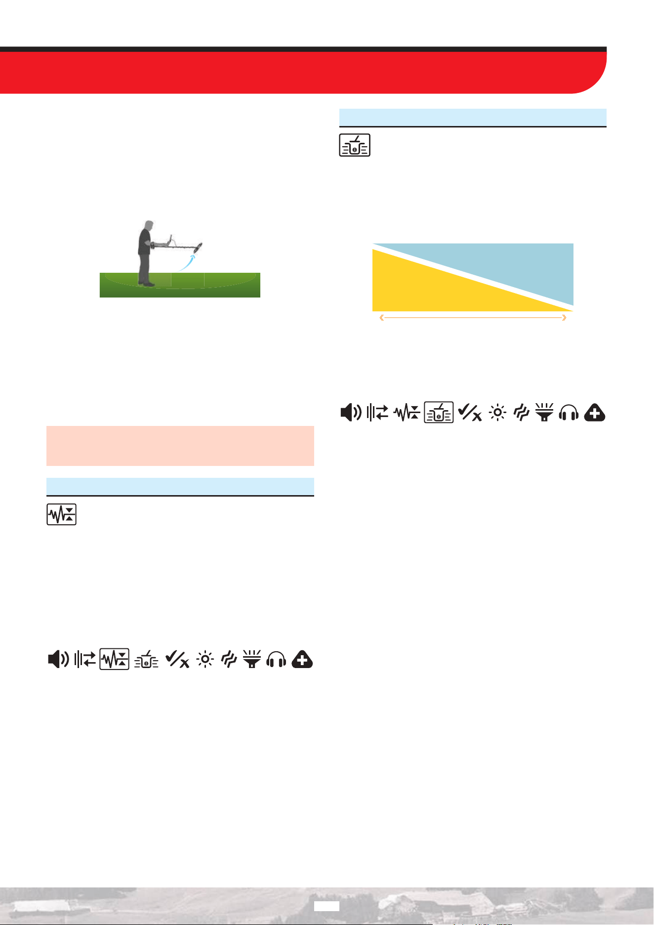
4. Deep Target Identification
This feature allows non-ferrous deep targets, which are
masked or detected as iron (ferrous), to be detected as
non-ferrous.
You can adjust the Deep Target Identification value between 1-3
and 3 is the default value.
This feature can be used in all modes except the Relic mode with
both Multi frequency and Single frequencies.
1 3
Deep Target Identification
Stability
Adjusting the Deep Target Identification
Press the Power / Settings button once. Use the Right and Left
buttons to select the Deep Target Identification setting. The
current Deep Target Identification value will be displayed on the
screen.
Use the Up and Down buttons to adjust the Deep Target
Identification setting between 1 and 3.
27
5. Notch (Accepting and Rejecting IDs)
On The LEGEND 2 device, IDs range from 1 to 99, and
each ID is represented by a single bar on the ID scale.
This provides users with precise control over each individual ID.
With the Accepting / Rejecting IDs (Notch) feature, users can
accept or reject any desired ID.
Forming a Customized Discrimination Pattern
Press the Power / Settings button once. Use the Right and Left
buttons to select the Notch (Accepting and Rejecting IDs).
Regardless of which discrimination pattern is selected, when the
Accepting / Rejecting IDs (Notch) feature is selected, the device
automatically switches to the Custom Discrimination Pattern (C),
and the selected Discrimination Pattern displayed next to the ID
scale is highlighted with a frame.
There are two options to create a Custom Discrimination Pattern:
Manual and Automatic.
Manual Notch:
Hold the coil stationary. The last Target ID number left on the
screen will be displayed, and an arrow-shaped cursor will appear
under the Target ID scale. In manual mode, Target ID selection can
be made one by one and sequentially.
Single Target ID Selection:
1. Move the cursor using the Up and Down buttons. Each time you
press a button, the Target ID numbers on the screen will change.
Select the ID you want to enable or disable.
2. Press the Pinpoint & Accept/Reject button. If the selected ID is
disabled, it will be enabled; if it is enabled, it will be disabled. You
can track the changes on the Target ID scale.
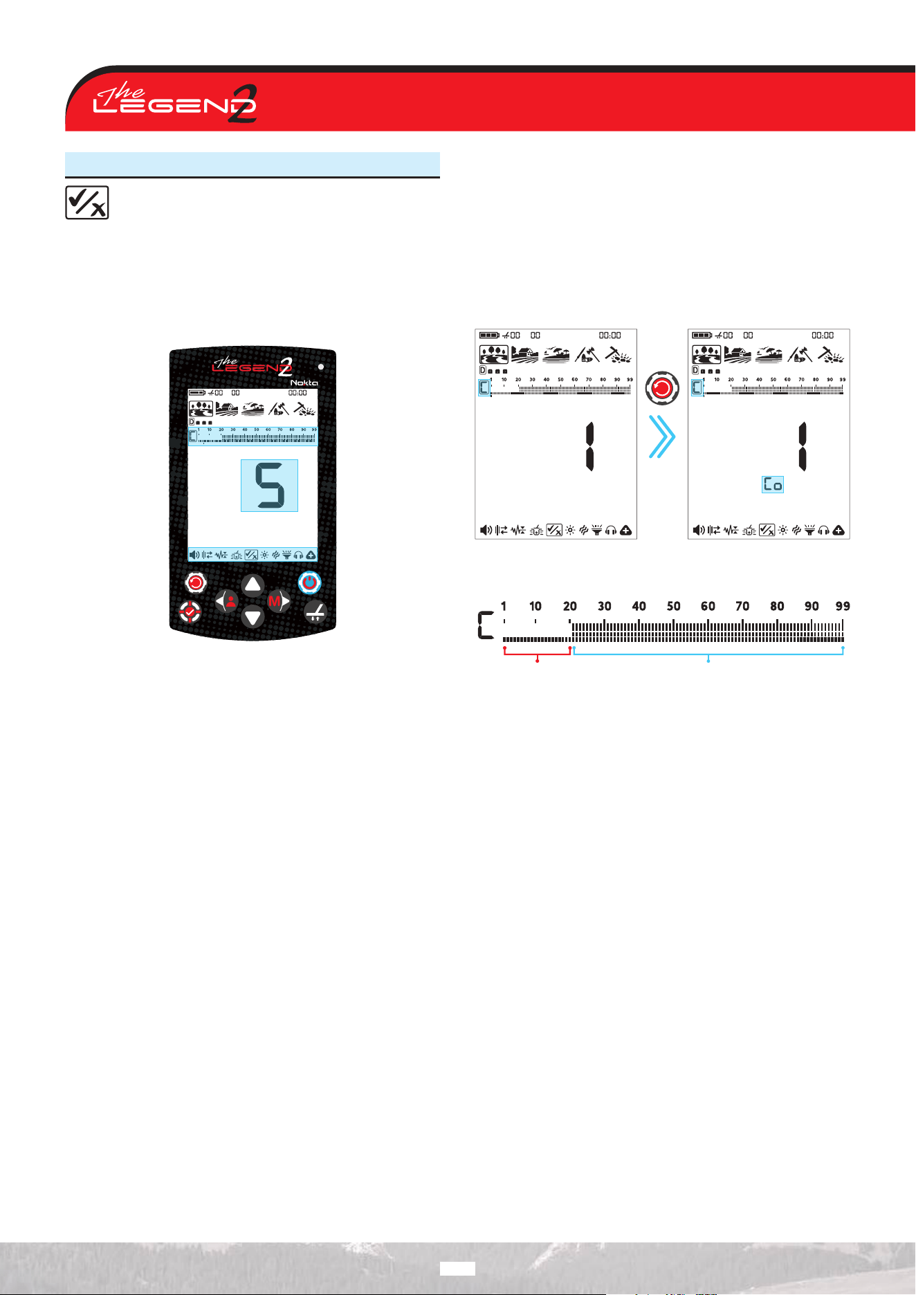
Sequential Target ID Selection:
1. Press the Quick Settings button. This activates consecutive
Target ID selection. Using the Up and Down buttons, move the
cursor at the bottom. Target IDs that are o are turned on, and
selected Target IDs are turned o.
When the setting is activated, the
letters “Co” are displayed on the screen.
Co: Sequential
Press
once
2. After you make the desired adjustment, pressing the Quick
Settings button will disable consecutive Target ID selection.
Rejected
IDs 1-20
Accepted
IDs 21-99
Automatic Notching:
1. In the Notch (Accepting and Rejecting IDs) setting, sweep the
search coil over the metal whose ID you want to turn o. The
cursor below the Target ID scale and the Target ID value indicate
the ID number you want to disable or enable.
2. Sweep the search coil to obtain the Target ID value, then press
the Pinpoint & Accept/Reject button to enable it if it is disabled,
or disable it if it is enabled.
Automatic Sensitivity Reduction
During automatic operation, if ID values fluctuate too much, press
the “Ground Balance” button to temporarily lower the Sensitivity
level. This allows the ID Enable/Disable process to be performed
more easily.
28
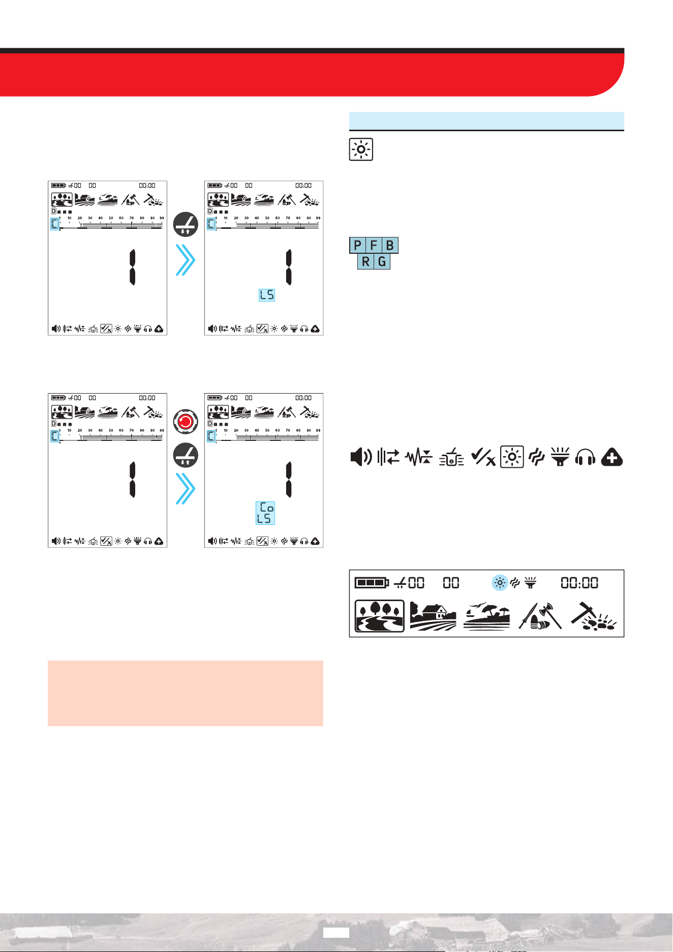
In the ID Enable / Disable setting, pressing the “Ground Balance”
button automatically lowers the Sensitivity level. The letters “LS”
are displayed on the screen.
LS: Low Sensitivity
Press
once
When both the “Automatic Sensitivity Reduction” and “Sequential
ID Enable / Disable” features are activated, the screen appears as
shown below:
Press
once
The LEGEND 2 does not produce a sound for rejected targets, but
it displays their ID values on the screen in the Notch (Accepting
and Rejecting IDs) setting.
When you re-enter the Notch (Accepting and Rejecting IDs)
setting, the cursor and Target ID remain in their last position.
You can press the Power / Settings button to exit the menu.
IMPORTANT! When you exit the Notch (Accepting and
Rejecting IDs) setting, the currently selected Discrimination
Pattern remains active. If you want to switch to the “C” Custom
Discrimination Pattern, you can change the Discrimination
Pattern from the quick settings.
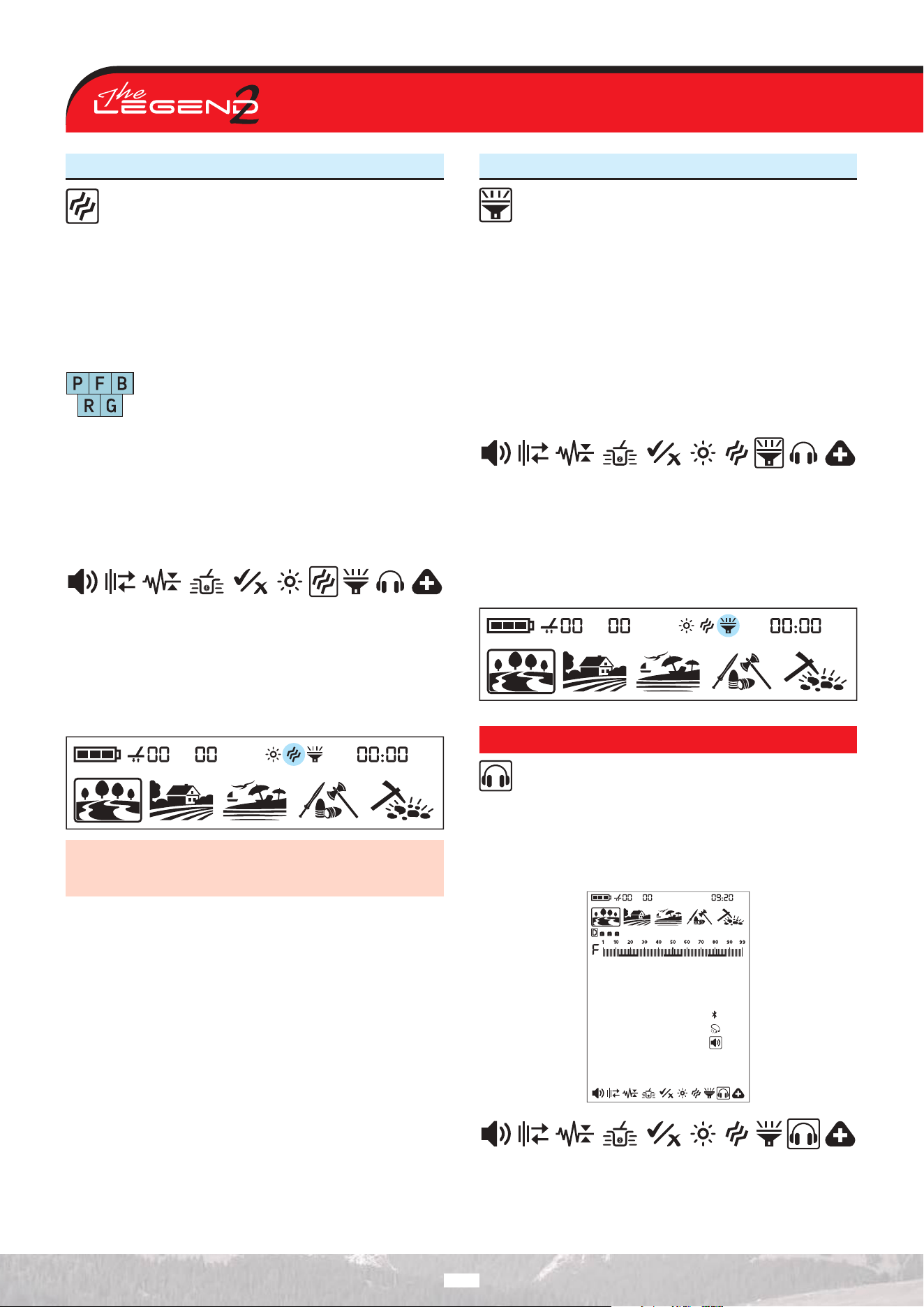
6. Screen and Keypad Backlight
It enables you to adjust the display backlight level
according to your personal preference.
It ranges from 0 to 5 and A1 to A5. At 0 level, the backlight is o.
At 1-5 levels, it will be continuously lit. At A1-A5 levels, it lights up
only for a short period of time when a target is detected or while
navigating the menu and then it goes o.
Park Field Beach
Relic
Gold
This setting is common to all modes; changes will
take eect in all modes.
Adjusting the Keypad Backlight
When the Screen Backlight setting is selected, you can turn the
keypad backlight on or o by pressing the Pinpoint & Acept/
Reject button.
The continuous operation of the backlight will aect power
consumption, which is not recommended. The backlight setting is
restored to the final saved setting when the device is turned o
and on again.
Adjusting the Backlight
1. Press the Power / Settings button once, and use the Right and
Left buttons to select the Screen Backlight setting.
2. Change the backlight level using the Up and Down buttons.
3. Press the Power / Settings button once to go back to the main
screen.
When the backlight is on, the backlight icon will be displayed in
the Info Bar at the top of the screen.
29
7. Vibration
This feature provides feedback to the user by producing a
vibration eect when a target is detected.
It can be used independently or together with the audio response.
When audio response is disabled, all responses during target
detection are provided to the user as vibration only.
The Vibration setting can be set to 0 (O) or 1 (On). At 0 vibration
is o. The magnitude of the vibration eect can vary according to
the depth of the target and the swinging speed.
Park Field Beach
Relic
Gold
This setting is common to all modes; changes will
take eect in all modes.
When you turn o and on the device, it will start with the last
vibration level you chose.
Adjusting the Vibration
1. Press the Power / Settings button once. Select vibration using
the Right and Left buttons. The current value will be displayed
on screen.
2. Change the level using the Up and Down buttons.
3. Press the Power / Settings button once to go back to the main
screen.
When the vibration is on, the vibration icon will be displayed in the
Info Bar at the top of the screen.
Even if the vibration is on, it will not generate a response for
targets while in the settings menu but only in the detection
screen.
8. LED Flashlight
Use this setting to operate a headlight that illuminates the
search area during night or low-light conditions.
LED Flashlight does not operate when the device is o. It is
recommended to turn it on only when necessary since its
operation consumes extra battery power.
LED Flashlight setting can be set to 0 (o) or to 1 (on). The LED
Flashlight will be o at each start up.
Turning the LED Flashlight On/O
1. Press the Power / Settings button once. Select LED Flashlight
using the Right and Left buttons. The current value will be
displayed on screen: 0 (O) or 1 (On).
2. Turn the flashlight On/O using the Up and Down buttons.
3. Press the Power / Settings button once to go back to the main
screen.
When the LED Flashlight is on, the flashlight icon will be displayed
in the Info Bar at the top of the screen.
AUDIO OPTIONS
This setting is used to select the audio output.
To select the audio output, choose the Audio Options setting from
the Settings menu. When this setting is selected, three dierent
audio output options are displayed on the screen. You can change
the audio output option using the Up and Down buttons. The
default audio output is the speaker.
30
1. Speaker
When the speaker icon in the sound options settings is
selected, the sound is emitted through the device’s speaker.
2. Bone Conduction Headphones
When the bone conduction headphones icon in the sound
options settings is selected, the sound is emitted through
the bone conduction headphones.
IMPORTANT! When the bone conduction headphone audio
output is selected, make sure that the bone conduction
headphones are connected. If the bone conduction headphones
are not connected, you will not receive any audio output from
the detector.
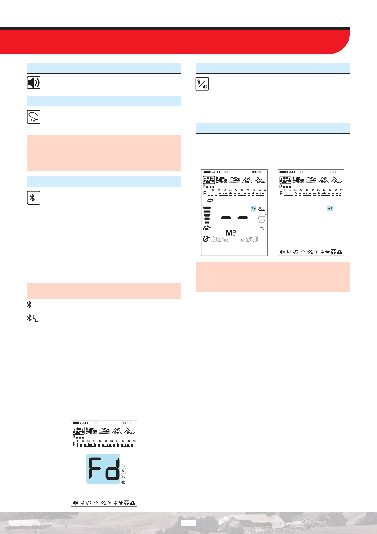
3. Bluetooth® Headphones
When the Bluetooth® icon in the sound options settings is
selected, The LEGEND 2 turns on Bluetooth® and enters
pairing mode. In pairing mode, the Bluetooth® icon blinks.
The device will search for the headphones it has been paired with
initially and try to connect to those. This will prevent the device
from connecting to other Bluetooth® devices when the Bluetooth®
setting is on. If you want to pair the device with dierent
Bluetooth® headphones (other than those it was initially paired
with) you must delete them from memory.
Once it pairs with any Bluetooth® headphones (Nokta BT
Headphones or others), one of the icons below will be displayed
in the Info Bar:
When headphones are connected, they will automatically turn
o if no sound is transmitted from the device for 14 minutes.
Standard Bluetooth® headphones connected.
aptX™ Low Latency headphones connected.
When pairing with Bluetooth® headphones is established, if one of
the icons above is selected, the sound is transmitted only through
the Bluetooth® headphones.
For more detailed info about the Nokta BT Headphones, please
read the instructions included with the headphones.
Deleting Paired Headphones From Memory
While in Bluetooth® setting, if the Pinpoint & Accept/Reject button
is pressed long, the letters ‘’Fd’’ will be displayed on screen for 2
seconds and the list of headphones that were paired with the
device before will be deleted. If you want to pair a new pair of
headphones after this, you must follow the pairing instructions
again.
4. Multiple Audio Output
When the Bluetooth® icon is selected in the Audio Options
settings and a Bluetooth® headphone connection is
established, the option to output audio through both the
Bluetooth® headphones and the device’s speaker becomes active.
In this mode, audio is transmitted simultaneously through the
Bluetooth® headphones and the device’s speaker.
5. Wired Headphones
Using the optionally available headphone adapter cable, you can
connect and use wired headphones with your device. When wired
headphones are connected to the device, a headphone icon will
appear on the display.
When a wired headphone is connected, it is detected
automatically, and the audio option cannot be changed
manually. To switch to another audio option, disconnect your
wired headphone.
31
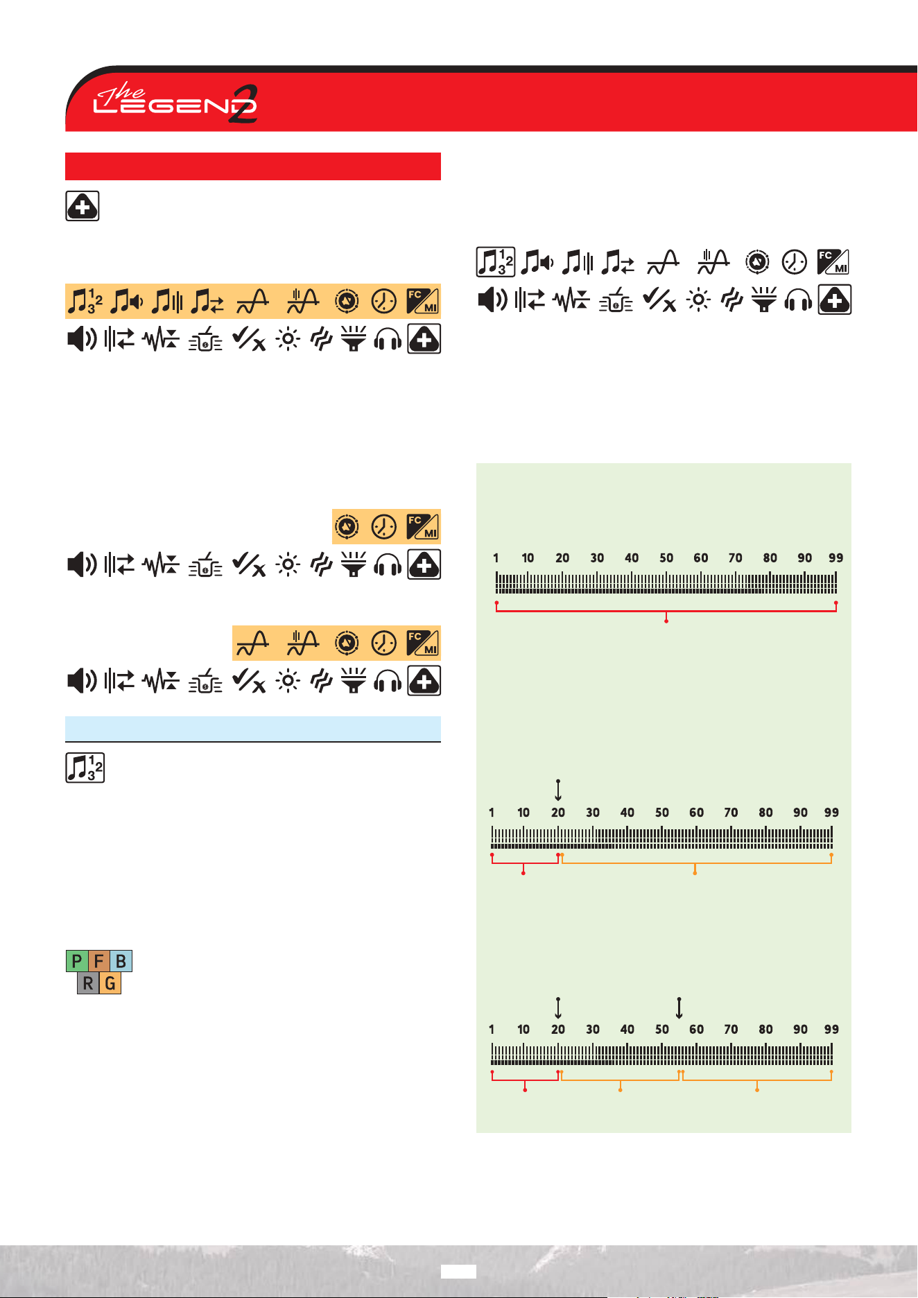
EXTRA SETTINGS
The Extra Settings menu contains nine dierent settings.
Seven of these are related to audio. The Clock setting and
the FerroCheck™ / Mineralization Indicator option are also located
in this menu. When this setting is selected, the settings included
in the Extra Settings menu are displayed on the screen.
Press the Up button once to enter the Extra Settings menu. Press
the Quick Settings button once to exit the Extra Settings menu.
In the Extra Settings menu, all features are displayed in Park,
Field, and Beach modes. However, the options available in Relic
and Gold modes are dierent.
Extra Settings Menu in Relic Mode:
Extra Settings Menu in Gold Mode:
1. Number of Tones
The LEGEND 2 divides the Target ID scale into multiple
zones allowing the user to make dierent tone
adjustments for targets that fall in each zone.
By changing the Number of Tones , you can decide on how many
zones you will divide the ID scale into. Thanks to this feature, you
can assign the same tone for all targets or assign a dierent tone
for each Target ID.
You can set the Number of Tones as 1, 2, 3, 4, 6, 99 or P (Tone
Pitch).
FieldPark
Relic
BeachPark
Relic
Gold
The Number of Tones setting only aects the mode
currently selected; changes made in one mode do
not aect the others.
The Number of Tones for the Gold and Relic modes is 1 and cannot
be changed.
Adjusting the Number of Tones
1. Press the Power / Settings button once. Select the extra settings
using the Right and Left buttons.
2. Press the Up button once to access the extra settings.
3. Using the Right and Left buttons, select the Number of Tones
setting. The selected setting will be shown framed.
4. The current Number of Tones will be displayed on the screen.
Select the Number of Tones using the Up and Down buttons.
5. To go back to the main screen, press the Power / Settings
button once.
1-Tone
The Target ID scale is not divided into any zones, hence there
is only 1-Tone zone. The LEGEND 2 generates the same tone
volume and tone frequency for all targets.
Zone-1
2-Tone
The Target ID scale is divided into 2 zones as ferrous and non-
ferrous. The default point that separates these 2 zones vary
based on the selected search mode (see below) and can be
changed using the Tone Break setting. The Tone Volume and
Tone Frequency can be adjusted for each zone.
Zone-1 Zone-2
Tone Break
3-Tone
The Target ID scale is divided into 3 zones. The Tone Volume
and Tone Frequency can be adjusted for each zone.
Tone
Break 1
Zone-1 Zone-2 Zone-3
32
Tone
Break 2
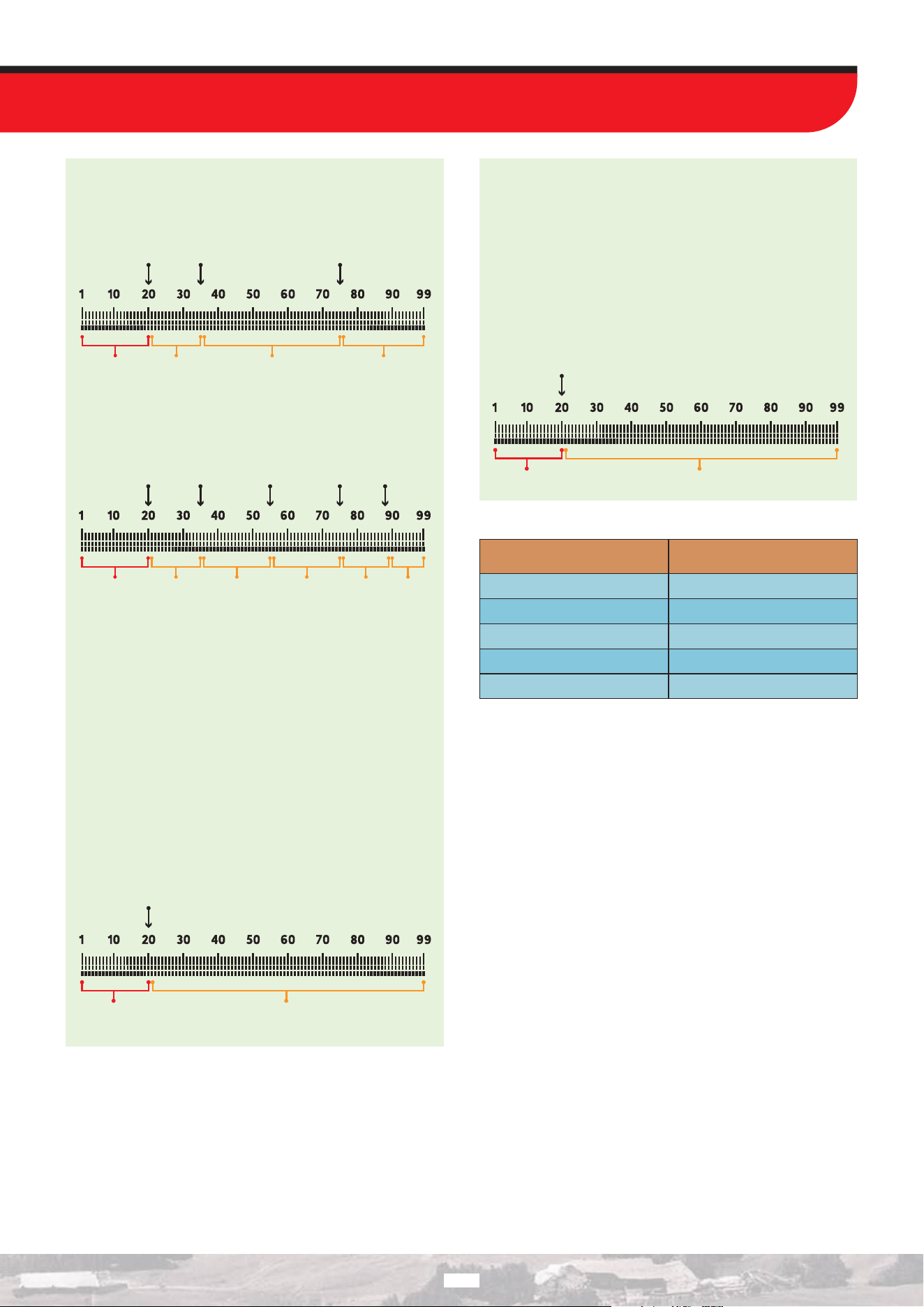
4-Tone
The Target ID scale is divided into 4 zones. The Tone Volume
and Tone Frequency can be adjusted for each zone.
Tone
Break 1
Tone
Break 2
Tone
Break 3
Zone-1 Zone-2 Zone-3 Zone-4
6-Tone
The Target ID scale is divided into 6 zones. The Tone Volume
and Tone Frequency can be adjusted for each zone.
Tone
Break 1
Tone
Break 2
Tone
Break 3
Tone
Break 4
Tone
Break 5
Zone-1 Zone-2 Zone-3 Zone-4 Zone-5 Zone-6
99-Tone
Just like the 2-Tone, the Target ID scale is divided into 2 zones
as ferrous and non-ferrous. The default point that separates
these 2 zones varies based on the selected search mode (see
below) and can be changed using the Tone Break setting.
The Tone Volume and Tone Frequency can be adjusted for each
zone.
The dierence between the 2-Tone and 99-Tone is that 99-
Tone generates a separate tone with a dierent frequency for
each Target ID.
The device generates lower frequency tones for ferrous range
and mid to high frequency tones for non-ferrous metals.
For more information, please refer to Tone Frequency setting.
Zone-1 Zone-2
Tone Break
Tone Pitch
Just like the 2-Tone, the Target ID scale is divided into 2 zones
as ferrous and non-ferrous. The default point that separates
these 2 zones varies based on the selected search mode (see
below) and can be changed using the Tone Break setting.
The Tone Volume and Tone Frequency can be adjusted for each
zone.
In Tone Pitch, as the coil approaches the target, the audio
frequency will change in proportion to the signal strength.
Zone-1 Zone-2
Tone Break
Default Number of Tones
Search Mode
PARK
FIELD
BEACH
RELIC
GOLD
2
2
2
1
1
Number of Tones
33
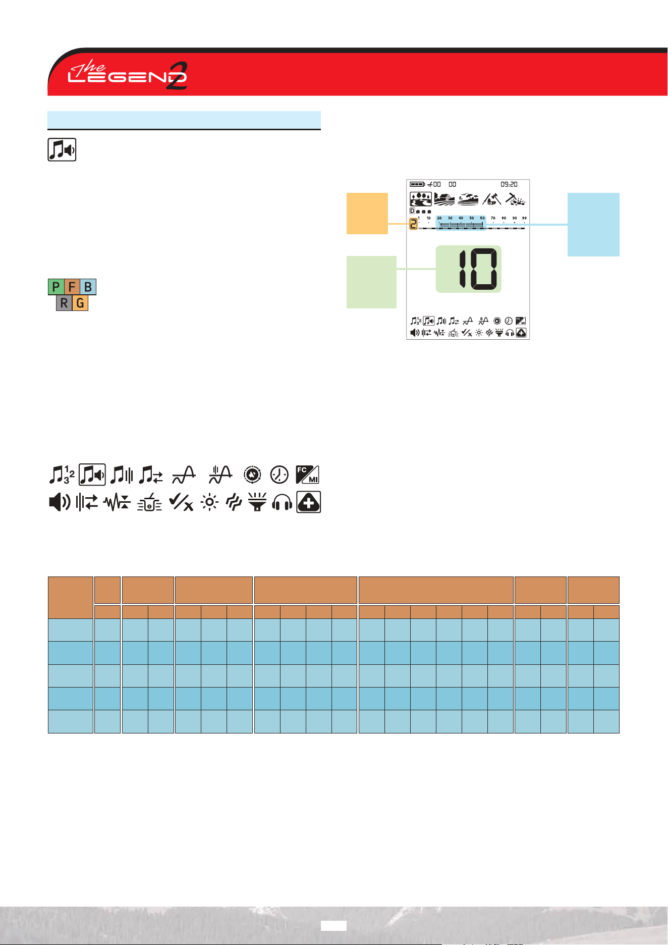
2. Tone Volume
This setting allows you to adjust the volume level for each
tone zone.
On trashy sites especially, detection is easier by turning o or
lowering the volume of unwanted target audio responses.
The Tone Volume can be adjusted for each target zone. For
example; in 1-Tone you can adjust the volume for 1 zone but in
6-Tone, you can adjust the volume of each zone separately.
Tone Volume setting range is from 0 to 10.
FieldPark
Relic
Gold
BeachPark
Relic
Tone Volume Level setting is specific to the selected
mode and the selected Target Tone Number, and
any changes made aect only the Target Tone
Number selected in that mode.
Tone Volume setting does not work in the Gold and Relic modes.
Adjusting the Tone Volume
1. Press the Power / Settings button once. Select the extra settings
using the Right and Left buttons.
2. The extra settings top menu will appear on the screen. Press
the Up button once.
3. Using the Right and Left buttons, select the Tone Volume
setting. The selected setting will be shown framed.
4. Press the Up button to go into the Tone Volume setting.
5. The Tone Volume of the selected zone will be displayed on
screen. To the left of the ID scale, the selected zone will be
displayed numerically.
Selected
target
zone
Tone
Volume
Level for
the selected
zone
Target IDs
for the
selected
zone
6. Using the Right and Left buttons, select the zone of which you
want to change the Tone Volume.
7. Once the zone is selected, you can change the Tone Volume
using the Up and Down buttons.
8. When the process is complete, press the Quick Settings button
once to return to the extra settings. To go back to the main screen,
press the Power / Settings button once.
Search
Mode
PARK
FIELD
BEACH
RELIC
GOLD
1-Tone 2-Tone 3-Tone 4-Tone 6-Tone 99-Tone
P-Tone Pitch
Z-1 Z-1 Z-2 Z-1 Z-2 Z-3 Z-1 Z-2 Z-3 Z-4 Z-1 Z-2 Z-3 Z-4 Z-5 Z-6 Z-1 Z-2 Z-1 Z-2
4
4
4
-
-
10
10
10
-
-
4
4
4
-
-
10
10
10
-
-
10
10
10
10
10
4
4
4
-
-
10
10
10
-
-
4
4
4
-
-
10
10
10
-
-
10
10
10
-
-
4
4
4
-
-
10
10
10
-
-
10
10
10
-
-
10
10
10
-
-
4
4
4
-
-
10
10
10
-
-
10
10
10
-
-
10
10
10
-
-
10
10
10
-
-
10
10
10
-
-
Default Tone Volumes
34
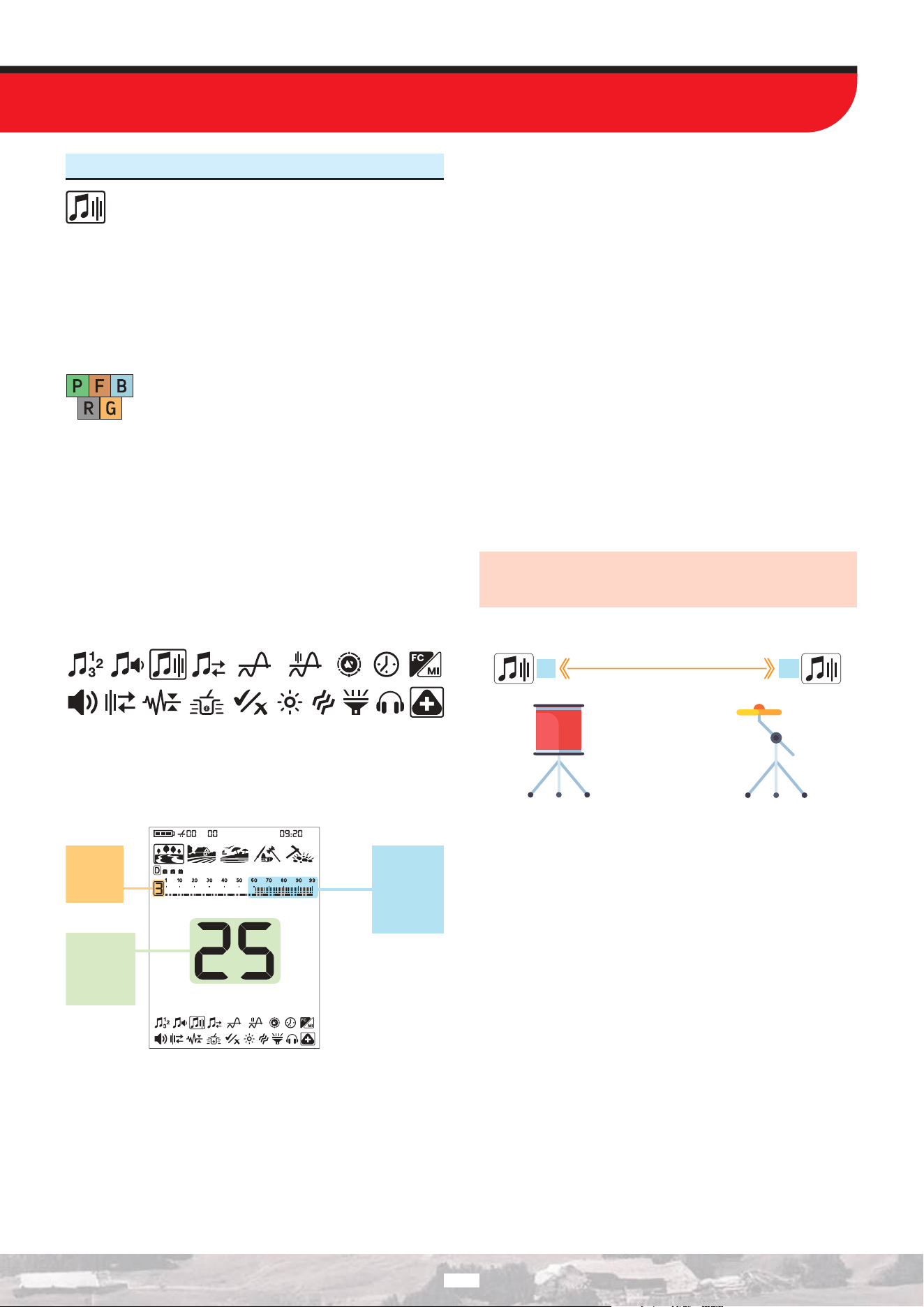
3. Tone Frequency
This setting allows you to adjust the Tone Frequency for
each tone zone.
This setting enables the users to easily identify targets by audio.
The Tone Frequency can be adjusted for each target zone. For
example; in 6-Tone, you can adjust the Tone Frequency of each of
the 6 zones separately.
Tone Frequency setting range is from 1 to 30.
FieldPark
Relic
Gold
BeachPark
Relic
Tone Frequency setting is specific to the selected
mode and the selected Target Tone Number, and
any changes made aect only the Target Tone
Number selected in that mode.
Tone Frequency setting does not work in the Gold and Relic
modes.
Adjusting the Tone Frequency
1. Press the Power / Settings button once. Select the extra settings
using the Right and Left buttons.
2. The extra settings top menu will appear on the screen. Press
the Up button once.
3. Using the Right and Left buttons, select the Tone Frequency
setting. The selected setting will be shown framed.
4. Press the Up button once to go into the Tone Frequency setting.
5. The Tone Frequency of the selected zone will be displayed
on screen. To the left of the ID scale, the selected zone will be
displayed numerically.
Selected
target
zone
Tone
Frequency
Level for
the selected
zone
Target IDs
for the
selected
zone
6. Using the Right and Left buttons, select the zone of which you
want to change the Tone Frequency.
7. Once the zone is selected, you can change the Tone Frequency
using the Up and Down buttons.
8. When the process is complete, press the Quick Settings button
once to return to the extra settings. To go back to the main screen,
press the Power / Settings button once.
Dierences between 2-Tone and 99-Tone
The Target ID scale is divided into 2 zones as ferrous and non-
ferrous both in 2-Tone and 99-Tone.
The Tone Frequency can be adjusted for both Zone-1 (Z-1) and
Zone-2 (Z-2) to any number between 1-30. The user may even
set both zones to the same number. However, this setting is used
dierently in the 99-tone.
In the 99-Tone, the Tone Frequency value set for Zone-1 (Z-1)
must be lower than the Tone Frequency value set for Zone-2 (Z-
2). For example; if the Tone Frequency value set for Zone-2 is 20,
the Tone Frequency level for Zone-1 should be between 1 and 19.
This applies to P-Tone Pitch as well.
IMPORTANT! To be able to distinguish between ferrous and
non-ferrous targets, the Tone Frequency levels selected should
be further away from each other.
Low Tone
Frequency
Tone Frequency Levels
High Tone
Frequency
1
30
35
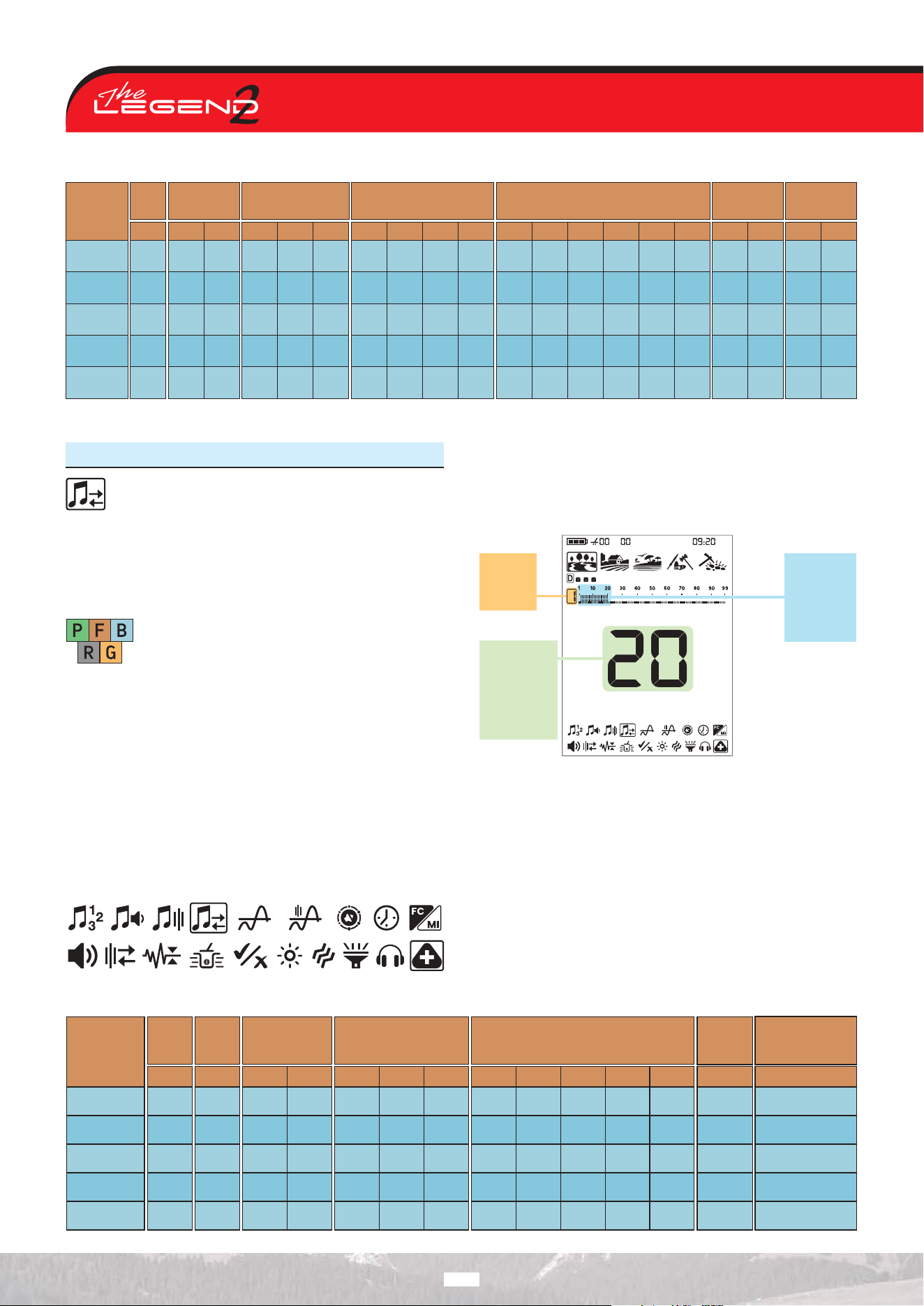
4. Tone Break
The Tone Break setting allows you to move the point that
separates the target zones.
The default Tone Break points may not provide you with the
distinction you need between the targets you are looking for. With
the Tone Break setting, you can adjust the start/end points of
target zones.
FieldPark
Relic
Gold
BeachPark
Relic
Tone Break setting is specific to the selected mode
and the selected Target Tone Number, and any
changes made aect only the Target Tone Number
selected in that mode.
When the Number of Tones is 1, Tone Break adjustment cannot
be made. Therefore, Tone Break setting does not work in the Gold
and Relic modes.
Adjusting the Tone Break
1. Press the Power / Settings button once. Select the extra setting
using the Right and Left buttons.
2. The extra settings top menu will appear on the screen. Press
the Up button once.
3. Using the Right and Left buttons, select the Tone Break setting.
The selected setting will be shown framed.
4. Press the Up button to go into the Tone Break setting.
5. The Tone Break point of the selected zone will be displayed
on screen. To the left of the ID scale, the selected zone will be
displayed numerically.
Selected
target
zone
Tone Break
point that
separates
Zone-1 and
Zone-2
Target IDs
for the
selected
zone
6. Using the Right and Left buttons, select the zone of which you
want to change the Tone Break.
7. Once the zone is selected, you can change the Tone Break point
using the Up and Down buttons.
8. When the process is complete, press the Quick Settings button
once to return to the extra settings. To go back to the main screen,
press the Power / Settings button once.
36
Search
Mode
1-Tone 2-Tone 3-Tone 4-Tone
6-Tone
99-Tone
P-Tone Pitch
PARK
FIELD
BEACH
RELIC
GOLD
Z-1 Z-1 Z-1 Z-1 Z-1 Z-1 Z-1Z-2 Z-2 Z-2 Z-2 Z-2 Z-2Z-3 Z-3 Z-3Z-4
Z-4
Z-5
Z-6
12
12
12
-
-
23
23
23
-
-
1
1
1
-
-
1
1
1
-
-
1
1
1
-
-
1
1
1
-
-
1
1
1
-
-
1
1
1
-
-
23
23
23
-
-
23
23
23
-
-
7
7
7
-
-
13
13
13
-
-
19
19
19
-
-
25
25
25
-
-
30
30
30
-
-
10
10
10
-
-
19
19
19
-
-
28
28
28
-
-
15
15
15
-
-
25
25
25
-
-
Default Tone Frequencies
Search
Mode
PARK
FIELD
BEACH
RELIC
GOLD
1-Tone
99-Tone
P-Tone Pitch
2-Tone 3-Tone 4-Tone 6-Tone
Z-1
-
-
-
-
-
Z-1
20
21
20
-
-
Z-1
20
21
20
-
-
Z-1
20
21
20
-
-
Z-1
20
21
20
-
-
Z-1
20
21
20
-
-
Z-1
20
21
20
-
-
Z-2
55
55
55
-
-
Z-3
75
75
75
-
-
Z-2
35
35
35
-
-
Z-2
35
35
35
-
-
Z-3
55
55
55
-
-
Z-4
75
75
75
-
-
Z-5
89
89
89
-
-
Default Tone Breaks
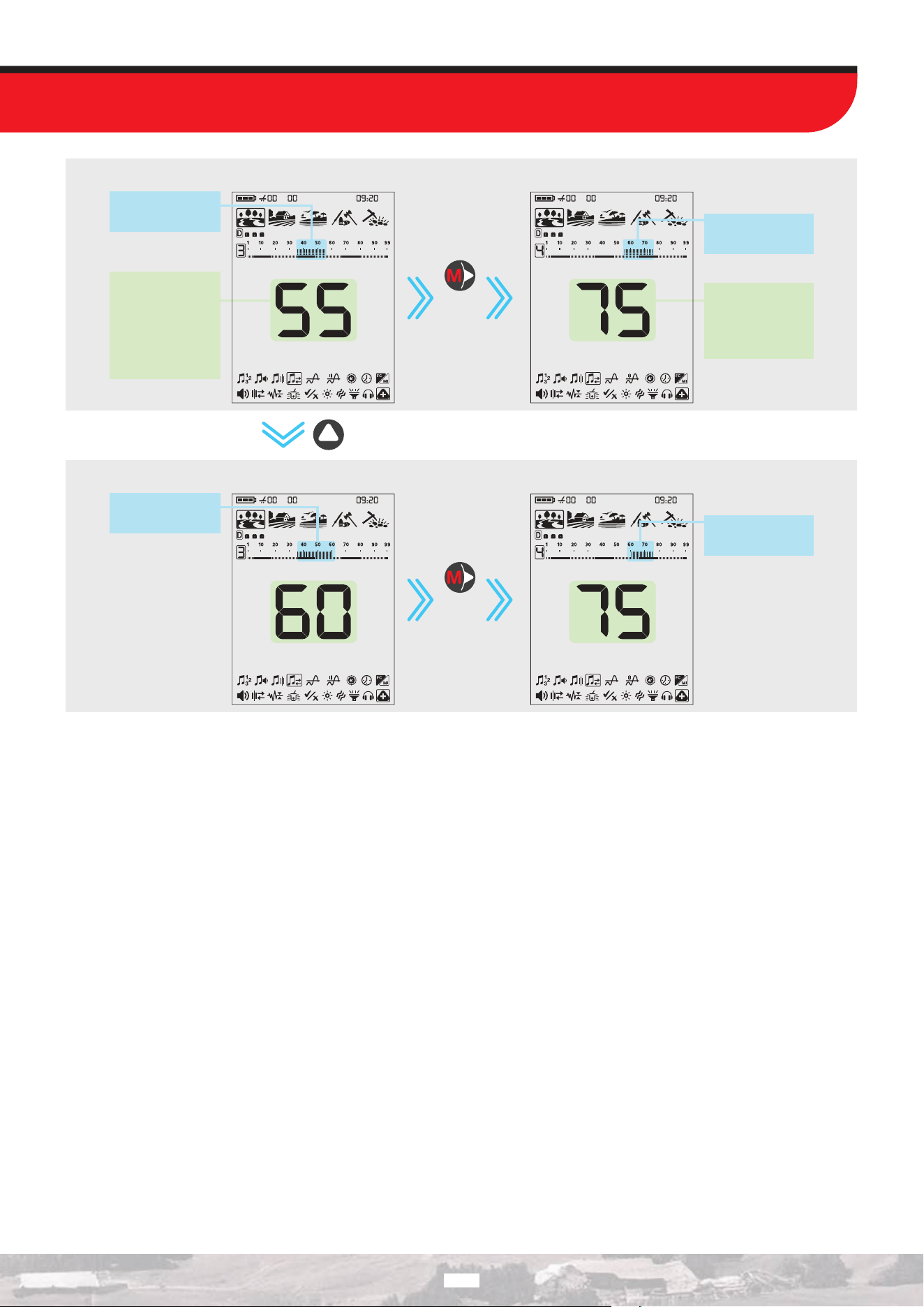
x5
Default Tone Breaks for Zones 3 and 4
After moving the Tone Break point from 55 to 60
Press
once
Press
once
Zone-3 Default ID
range: 36-55
Zone-3 Target ID
range: 36-60
Zone-4 Target ID
range: 61-75
Zone-4 Default ID
range: 56-75
Tone Break Point
that Separates
Zone-3 and
Zone-4
Tone Break Point
that Separates
Zone-4 and
Zone-5
37
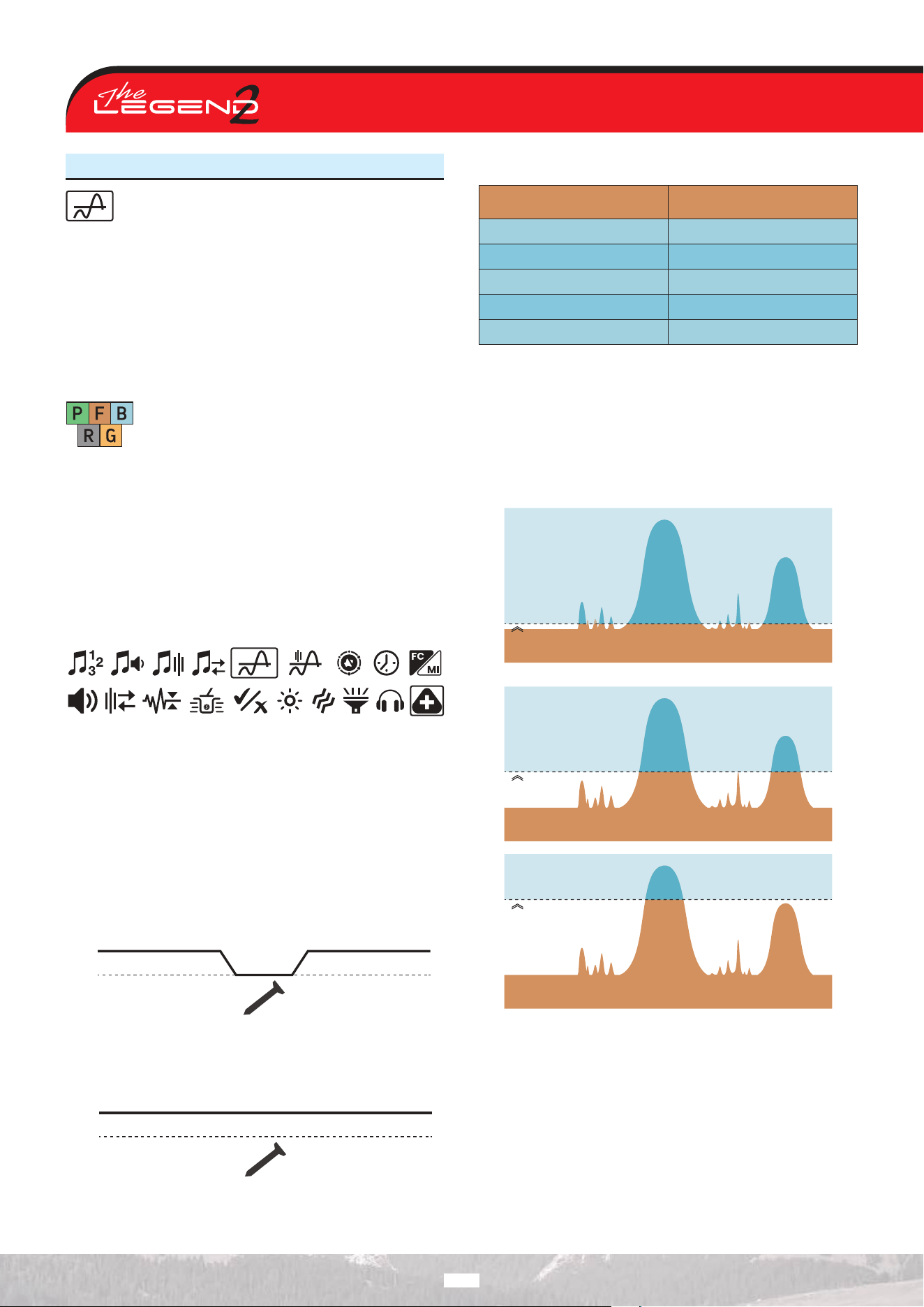
5. Threshold Level
This setting helps users identify targets more easily and
makes the sounds of weak signals from small targets,
such as gold nuggets, easier to hear.
When the Threshold Level setting is activated, The LEGEND 2
generates a sound which is continuously heard in the background
and this sound is called the ‘’Threshold’’.
Threshold Level range is from 0 to 30.
The frequency of the threshold tone can be adjusted by the
Threshold Tone Frequency setting.
FieldPark
Relic
Gold
BeachPark
Relic
Threshold Level setting only aects the mode
currently selected; changes made in one mode do
not aect the others.
There is no Threshold Level setting in Relic mode.
Adjusting the Threshold Level
1. Press the Power / Settings button once. Select the extra settings
using the Right and Left buttons.
2. The extra settings top menu will appear on the screen. Press
the Up button once.
3. Using the Right and Left buttons, select the Threshold Level
setting. The selected setting will be shown framed.
4. The current Threshold Level will be displayed on screen. Select
the Threshold Level using the Up and Down buttons.
5. When the process is complete, you can return to the settings by
pressing the Quick Settings button once. To return directly to the
main screen, press the Power / Settings button once.
Threshold Tone for Rejected Targets
In Park, Field and Beach modes
The Threshold tone will blank to indicate detection of a rejected
target.
Threshold Tone
Blanking Level
Rejected Target
In Gold mode
When The LEGEND 2 detects a rejected target the threshold tone
continues in the background.
Threshold Tone
Blanking Level
Rejected Target
Default Threshold Levels
Search Mode
PARK
FIELD
BEACH
RELIC
GOLD
Threshold Level
0
0
0
-
14
The Threshold Level directly impacts the detection depth of
smaller and deeper targets. If the threshold is set too low (0),
weak signals of smaller or deeper targets may be missed. On the
contrary, if the threshold is set too high (30), the device will be
noisier, the threshold sound will be loud and the target responses
will not be distinguished. Therefore, it is recommended to adjust
it to a level where you can still hear the slight audio variations
caused by a target.
High Threshold
Level (30)
Low Threshold
Level (0)
Optimal Threshold
Level
Threshold Level
Threshold Level
Big signal
Big signal
Big signal
Small signal
Small signal
Small signal
Noise
Noise
Noise
Noise
Noise
Noise
Threshold Level
38
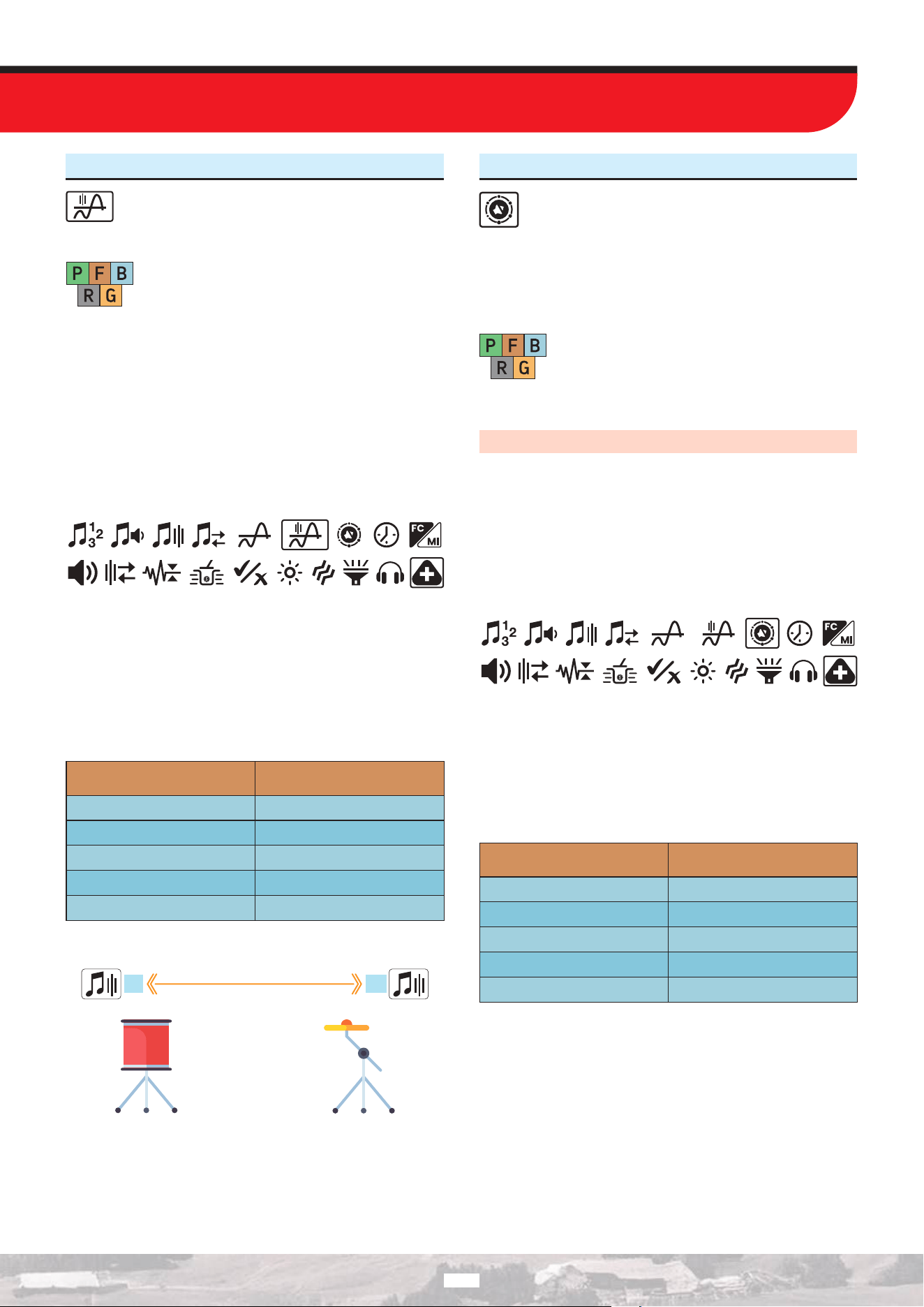
6. Threshold Frequency
This setting is used to adjust the tone frequency of the
background hum. It oers a very wide frequency range.
Threshold Frequency range is from 1 to 30.
FieldPark
Relic
Gold
BeachPark
Relic
Threshold Frequency only aects the mode
currently selected; changes made in one mode do
not aect the others.
There is no Threshold Frequency setting in Relic mode.
Adjusting the Threshold Frequency
1. Press the Power / Settings button once. Select the extra setting
using the Right and Left buttons.
2. The extra settings top menu will appear on the screen. Press
the Up button once.
3. Using the Right and Left buttons, select the Threshold Frequency
setting. The selected setting will be shown framed.
4. The current Threshold Frequency value will be displayed on
screen. Select the Threshold Frequency using the Up and Down
buttons.
5. When the process is complete, you can return to the settings by
pressing the Quick Settings button once. To return directly to the
main screen, press the Power / Settings button once.
Default Threshold Frequencies
Search Mode
PARK
FIELD
BEACH
RELIC
GOLD
Threshold Frequency
10
10
10
-
13
Low Threshold
Frequency
Threshold Frequency Levels
High Threshold
Frequency
1
30
7. Audio Gain
The LEGEND 2 oers users the Audio Gain setting to
convert target signals into audio using dierent response
models. With the Audio Gain setting, users can select the
signal-to-audio response model that best suits their preferences.
This feature is eective in increasing or decreasing the output
volume of weak target signals.
FieldPark
Relic
Gold
BeachPark
Relic
The Audio Gain setting only aects the mode
currently selected; changes made in one mode do
not aect the others.
The audio gain can be set to values between 1 and 6.
IMPORTANT! Audio Gain does NOT increase depth.
Adjusting the Audio Gain
1. Press the Power / Settings button once, then use the Right and
Left buttons to select the extra settings.
2. The extra settings top menu will appear on the screen. Press
the Up button once.
3. Use the Right and Left buttons to select the Audio Gain setting.
The selected setting will be highlighted with a frame.
4. The current Audio Gain value will be displayed on the screen.
Use the Up and Down buttons to select your desired value.
5. When the operation is complete, you can return to the settings
by pressing the Quick Settings button once. To return directly to
the main screen, press the Power / Settings button once.
Default Audio Gain Settings
Search Mode
PARK
FIELD
BEACH
RELIC
GOLD
Audio Gain
1
1
5
3
1
39
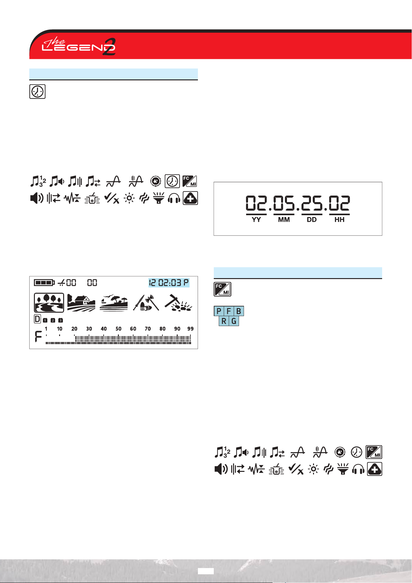
8. Clock and Usage Duration
The LEGEND 2 has a built in clock that is located in the
right upper corner of the screen.
Setting the Clock
1. Press the Power / Settings button once, then use the Right and
Left buttons to select the extra settings.
2. The extra settings top menu will appear on the screen. Press
the Up button once.
3. Use the Right and Left buttons to select the Clock setting. The
selected setting will be highlighted with a frame.
4. Press the Up button once on the selected setting. This will allow
you to start setting the time on The LEGEND 2 device.
5. You will see numbers and a small line underneath them in the
upper right corner. The line will be under the clock section. Using
Up and Down buttons, first choose between 24-hour or 12-hour
clock options (if 12-hour clock is selected, letter A for AM or letter
P for PM will come up).
6. Then using the Right and Left buttons select the hour and
minutes and set the time using the Up and Down buttons.
7. When the process is complete, press the Quick Settings button
once to return to the extra settings. To return directly to the main
screen, press the Power / Settings button once.
To provide LEGEND 2 users with a unique experience, the device
records the total operating time from the moment it is first turned
on and shares this information with the user.
Find Out the Usage Period
1. Press the Power / Settings button once, then use the Right and
Left buttons to select the extra settings.
2. The extra settings top menu will appear on the screen. Press
the Up button once.
3. Use the Right and Left buttons to select the Clock setting. The
selected setting will be highlighted with a frame.
4. When the Time setting is selected, press and hold the Pinpoint
& Accept/Reject button. While you continue holding it, the usage
time will be displayed in the upper-right corner of the screen.
In the usage time display, the fields shown as YY-MM-DD-HH
indicate the device’s total operating time in Years, Months, Days,
and Hours, respectively.
5. When the process is complete, press the Quick Settings button
once to return to the settings. To return directly to the main
screen, press the Power / Settings button once.
9. FerroCheck™ / Mineralization Option
This setting allows the FerroCheck™ bars on the main
screen to also serve as a mineralization indicator.
Park Field Beach
Relic
Gold
This setting is common to all modes; changes will
take eect in all modes.
Changes made to this setting are stored in the device’s memory,
and when the device is powered o and on, it starts with the last
selected setting.
Switching from the FerroCheck™ Indicator to the Mineralization
Indicator
1. Press the Power / Settings button once, then use the Right and
Left buttons to select the extra settings.
2. The extra settings top menu will appear on the screen. Press
the Up button once.
3. Use the Right and Left buttons to select the FerroCheck™ /
Mineralization setting. The selected setting will be highlighted with
a frame.
4. The current value representing the indicator will be displayed
on the screen. Use the Up and Down buttons to select your
desired indicator. A value of 0 means the Mineralization indicator
is displayed on the main screen, while a value of 1 means the
FerroCheck™ indicator is displayed on the main screen.
5. When the process is complete, press the Quick Settings button
once to return to the settings. To return directly to the main
screen, press the Power / Settings button once.
40
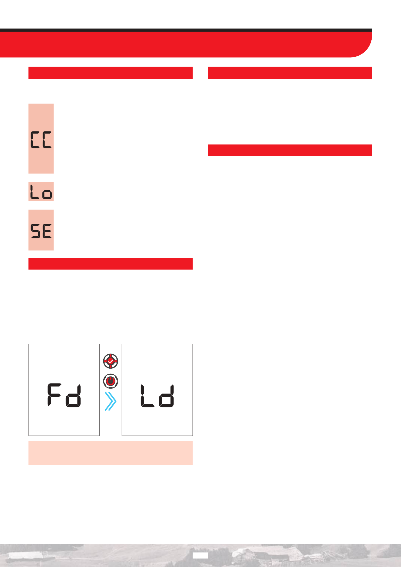
WARNING MESSAGES
The device will shut down shortly after one of the below messages
is displayed on screen:
Check Coil (CC)
It indicates an interruption in the search coil
transmitter signal. The search coil connector may be
unattached, loose or disconnected. If you own another
detector with the same coil connector, please be sure
that you have not attached the wrong coil by mistake.
If none of the above exists, the search coil or its cable
may have a defect. If the issue continues when you
change the search coil, there may be an issue in the
coil control circuit.
Low Battery (Lo)
When battery is depleted, ‘’Lo’’ message appears on
display and the device shuts down.
System Error (SE)
Turn the device back on if the device shuts down after
this warning. If the problem persists, reset the device
by pressing and holding the Power / Settings button
for 30 seconds. If the problem still exists, contact
technical service.
REVERTING BACK TO FACTORY DEFAULTS
To restore The LEGEND 2 device to factory settings, press and hold
the Pinpoint & Accept/Reject button and the Power / Settings
button while the device is powered o. The letters “Fd” (Factory
Default) will appear on the screen. To proceed with the factory
reset, continue holding the buttons until the letters “Ld” appear
on the screen (approximately 3 seconds). When “Ld” is displayed,
release both the Pinpoint & Accept/Reject button and the Power
/ Settings button. Your device will restart and return to factory
default settings.
Press
and
hold
IMPORTANT! If the Pinpoint & Accept/Reject button is released
while the letters “Fd” are displayed on the screen, the device
will power on without returning to factory settings.
SOFTWARE UPDATE
The LEGEND 2 has software update capability. All software
updates made after the device is released to the market will
be announced on the product’s web page along with updating
instructions.
System Version Information:
The software version of The LEGEND 2 will be displayed at the
upper right corner each time you turn the detector on.
HEADPHONES
The LEGEND 2 comes with Bluetooth® wireless headphones. The
Bluetooth
® headphones are NOT waterproof and should not be
exposed to water.
The wireless connection will work as long as the system box of
the device is not submerged in the water. In other words, you can
use your wireless headphones while searching in shallow water
with the coil submerged underwater. Please remember though,
that the wireless headphones should not contact with water.
In case of the system box being submerged underwater, the
wireless connection will not work. In this case, you need to
purchase our optional Nokta Waterproof Headphones for land
and underwater use. If you will not submerge the headphones
underwater but just the system box, then you can also purchase
our Nokta Headphones with waterproof connector.
For land use only, you can also purchase our optional headphones
adapter should you want to use The LEGEND 2 with your own
wired headphones.
41

TECHNICAL SPECIFICATIONS 55000609
Operating Frequencies : Multi (3), 4 kHz, 10 kHz, 15 kHz, 20 kHz, 40 kHz
Audio Frequencies
: 100 Hz - 1200 Hz adjustable
Search Modes
: 5 (Park / Field / Beach / Relic / Gold)
Custom User Profiles
: 15
Audio Tones
: 99
Tone Volume
: Yes
Tone Break
: Yes
Tone Frequency
: Yes
Adjustable Threshold
: Yes
Notch Filter
: Yes
Ground Suppressor : Yes
Ground Balance : Automatic / Manual / Tracking
Pinpoint
: Yes
ID in Pinpoint
: Yes
Frequency Shift
: Yes
Noise Cancellation : Yes
Vibration : Yes
Sensitivity Setting
: 30 levels
Target ID
: 1-99
Search Coils
: Waterproof DD Search Coil & Cover - LD21 (8’’ × 5.5’’ / 21 cm x 14 cm)
.Waterproof DD Search Coil & Cover - LD28 (11’’ / 28 cm)
Display
: Custom LCD
Backlight
: Yes
Keypad Light
: Yes
LED Flashlight
: Yes
Weight : 1.2 kg (2.6lbs.) including the search coil
Length
: 63 cm - 145 cm (25” - 57”) adjustable
Battery : 6700 mAh Lithium Ion
Warranty
: 3 years
The Bluetooth
® word mark and logos are registered trademarks owned by Bluetooth® SIG, Inc.
Qualcomm
® aptX™ is a product of Qualcomm Technologies,
Inc.
Nokta Detectors reserves the right to change the design, specifications or accessories without notice and without any obligation or liability
whatsoever.
42
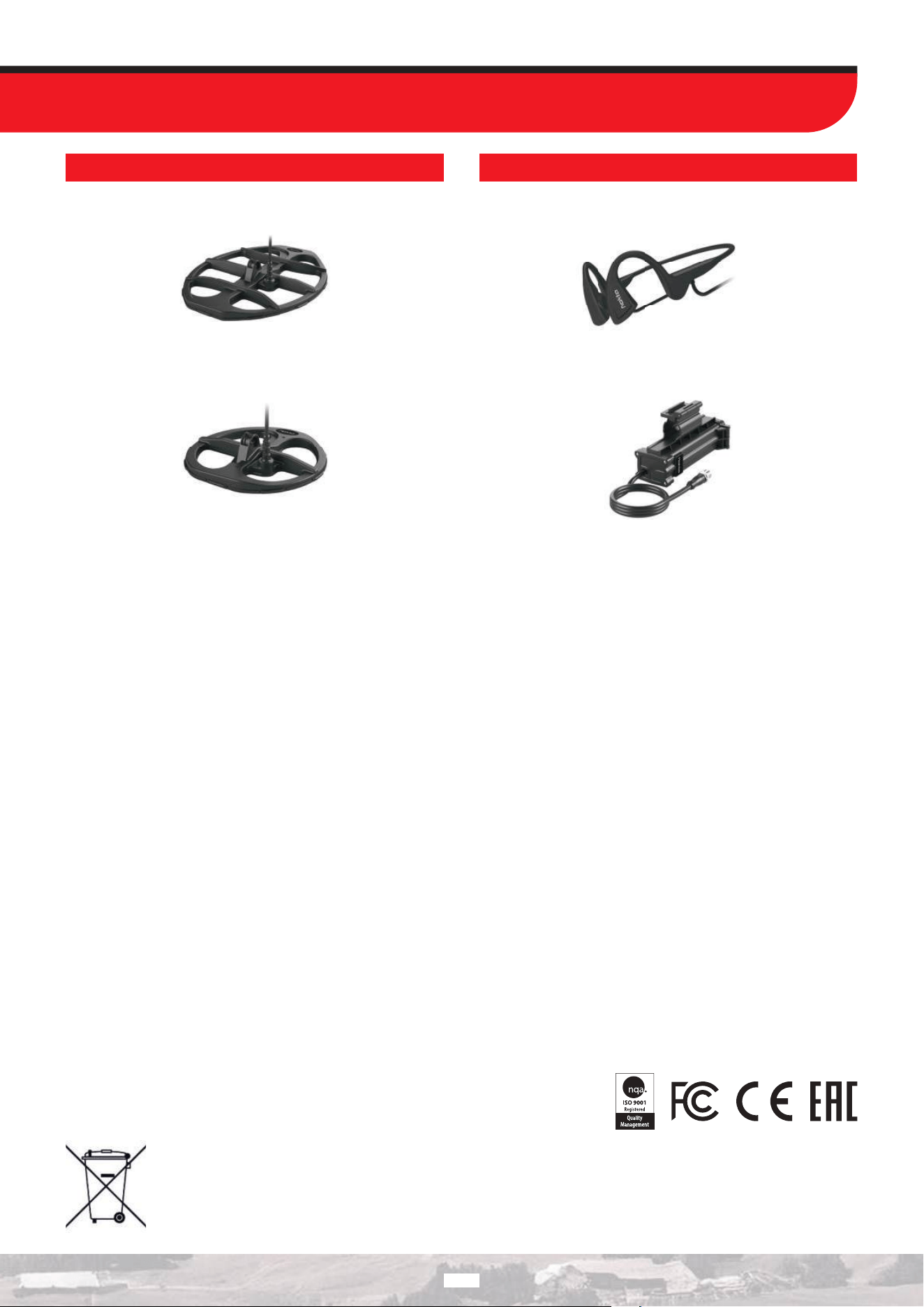
RECOMMENDED ACCESSORIES
Waterproof DD Search Coil & Cover – LD38
(15’’ X 12”/ 38 cm X 30 cm)
Waterproof DD Search Coil & Cover – LD22 (9’’ / 22 cm)
Bone Conduction Headphones
External Waterproof Battery
43
For Consumers within the European Union: Do not
dispose of this equipment in general household waste.
The crossed wheeled bin symbol on this equipment
indicates this unit should not be disposed of in general
household waste, but recycled in compliance with local
government regulations and environmental requirements.
FCC STATEMENT
This device complies with Part 15 of the FCC Rules. Operation is subject
to the following two conditions: (1) this device may not cause harmful
interference, and (2) this device must accept any interference received,
including interference that may cause undesired operation.

1

FCC Warning:
This equipment has been tested and found to comply with the limits for a Class B digital device,
pursuant to part 15 of the FCC Rules. These limits are designed to provide reasonable protection
against harmful interference in a residential installation. This equipment generates, uses and can
radiate radio frequency energy and, if not installed and used in accordance with the instructions, may
cause harmful interference to radio communications. However, there is no guarantee that interference
will not occur in a particular installation. If this equipment does cause harmful interference to radio or
television reception, which can be determined by turning the equipment off and on, the user is
encouraged to try to correct the interference by one or more of the following measures:
• Reorient or relocate the receiving antenna.
• Increase the separation between the equipment and receiver.
• Connect the equipment into an outlet on a circuit different from that to which the receiver is
connected.
• Consult the dealer or an experienced radio/TV technician for help.
Caution: Any changes or modifications to this device not explicitly approved by manufacturer could
void your authority to operate this equipment.
This device complies with part 15 of the FCC Rules. Operation is subject to the following two
conditions: (1) This device may not cause harmful interference, and (2) this device must accept any
interference received, including interference that may cause undesired operation.
The device has been evaluated to meet general RF exposure requirement.

w w w . n o k t a d e t e c t o r s . c o m