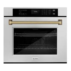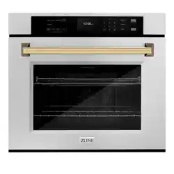

www.zlinekitchen.com
Installation Manual
SINGLE WALL OVEN

ZLINE Kitchen and Bath provides Attainable Luxury, where the kitchen and bath of your dreams
is never out of reach. Through our unique designs and unparalleled quality, we’re dedicated to
providing you an elevated experience in the heart of your home. With an endless selection of
features and finishes, our inspiration is your reality.

WARNING: This product can expose you to chemicals including nickel, which is known to the
State of California to cause cancer. For more information, go to www.P65Warnings.ca.gov.
ZLINE is fueled by a passion for innovation; A relentless pursuit of bringing the highest end
luxury designs and professional features into everyone’s homes. Because we continually strive to
improve our products, we may change specifications and designs without prior notice.

TABLE OF CONTENTS
IMPORTANT SAFETY INSTRUCTIONS � � � � � � � � � � � � � � � � � � � 1
BEFORE INSTALLATION � � � � � � � � � � � � � � � � � � � � � � � � � � � � � � � 4
Product Specifications � � � � � � � � � � � � � � � � � � � � � � � � � � � 4
Tools and Parts � � � � � � � � � � � � � � � � � � � � � � � � � � � � � � � 5
Electrical Requirements � � � � � � � � � � � � � � � � � � � � � � � � � � 6
INSTALLATION � � � � � � � � � � � � � � � � � � � � � � � � � � � � � � � � � � � � � � 9
Cutout Dimensions � � � � � � � � � � � � � � � � � � � � � � � � � � � � � 9
Step 1 - Unpack The Oven � � � � � � � � � � � � � � � � � � � � � � � � 9
Step 2 - Remove The Oven Door � � � � � � � � � � � � � � � � � � � � 10
Step 3 - Install Oven � � � � � � � � � � � � � � � � � � � � � � � � � � � � 11
Step 4 - Electrical Grounding Instructions � � � � � � � � � � � � � � � � 11
Step 5 - Mount The Oven � � � � � � � � � � � � � � � � � � � � � � � � �15
Step 6 - Replace The Door � � � � � � � � � � � � � � � � � � � � � � � �15
Step 7 - Complete Installation � � � � � � � � � � � � � � � � � � � � � � �16
WARRANTY � � � � � � � � � � � � � � � � � � � � � � � � � � � � � � � � � � � � � � � � 17

1
Proper Installation
WARNING
If the information in this manual is not followed exactly, a fire or
explosion may result causing property damage, personal injury, or
death�
Before beginning installation, please read and follow these important instructions for the
safety of your home and the people living in it. Always read and obey all safety measures.
To reduce the risk of fire, electrical shock, injury to persons, or damage when using the
oven, follow basic precautions, including the following:
PROPER INSTALLATION
This appliance must be properly installed and electrically grounded by a qualified
technician. Connect only to a properly grounded outlet. See “Step 4 - Electrical
Grounding Instructions” on page 11.
• This appliance should be serviced only by a qualified service technician. Contact the
nearest authorized service center for examination, repair, or adjustment.
• Do not repair or replace any part of the oven unless specifically recommended by a
professional. Refer service to an authorized servicer.
• Do not operate this appliance if it is not working properly or if it has been damaged
until an authorized servicer has examined it.
• Install this appliance only in accordance with the installation instructions.
• Use this oven only as intended by the manufacturer. If you have any questions, contact
ZLINE at 1-614-777-5004.
• Do not cover or block any openings on this appliance.
• Do not use corrosive chemicals, vapors, or nonfood products in this appliance. This
type of oven is specifically designed to heat or cook. It is not designed for industrial or
laboratory use. The use of corrosive chemicals in heating or cleaning will damage the
appliance.
• The manufacturer will not be responsible for any damage to property or to persons
caused by incorrect installation, improper use of the appliance, or failure to heed the
warnings listed, and the warranty will be voided.
• Do not overcook food. Carefully attend oven if paper, plastic or other combustible
materials are placed inside the oven.
• Do not use the cavity for storage purposes. Do not leave paper products, cooking
utensils or food in the cavity when not being used.
IMPORTANT SAFETY INSTRUCTIONS

2
Personal Safety
IMPORTANT SAFETY INSTRUCTIONS
TO REDUCE THE RISK OF FIRE INSIDE THE OVEN
• Do not store flammable materials in or near the oven.
• Do not use water on a grease fire. Smother fire or use a dry chemical or foam-type
extinguisher.
• It is highly recommended that a fire extinguisher be readily available and highly visible
next to any cooking appliance.
• Do not overcook food. Carefully oversee oven if paper, plastic, or other combustible
materials are placed inside the oven.
• Do not use the oven for storage purposes. Do not leave paper products, cooking
utensils, or food in the oven when not being used.
• If materials inside the oven should ignite, keep the door closed. Turn oven off and
disconnect the circuit at the circuit breaker box.
• Be sure the cooling fan runs whenever the oven is in operation. If the fan does not
operate, do not use the oven. Call an authorized service provider.
• NEVER use this appliance as a space heater to heat or warm the room. Doing so may
result in carbon monoxide poisoning.
PERSONAL SAFETY
• Do not allow children to use this appliance unless closely supervised by an adult.
Children and pets should not be left alone or unattended in the area where the
appliance is in use. Never allow children to sit or stand on any part of the oven.
• For personal safety, wear proper clothing. Loose-fitting clothes or garments with
hanging sleeves should never be worn while using this appliance.
• Tie long hair so that it doesn’t hang loose.
• Do not touch heating elements or interior surfaces of oven.
• The heating elements may be hot even though they are dark in color. Interior surfaces
of an oven become hot enough to cause burns.
• During and after use, do not touch or let clothing or other flammable materials contact
the heating elements or the interior surfaces of the oven until they have had sufficient
time to cool.
• Please note that the trim on the top and sides of the oven door may become hot
enough to cause burns.
• Use care when opening the door. Open the door slightly to let hot air or steam escape
before removing or replacing food.

3
Personal Safety
IMPORTANT SAFETY INSTRUCTIONS
• Do not heat unopened food containers. Build-up of pressure may cause the container
to burst and cause injury.
• Always place oven racks in desired location while oven is cool. If a rack must be
moved while oven is hot, do not let potholder contact the hot heating elements.
• Use only dry potholders or oven mitts. Moist or damp potholders on hot surfaces may
result in burns from steam. Do not use a towel or other bulky cloth.
SELF CLEANING OVEN SAFETY
• Before self-cleaning the oven, remove the broiler pan, oven racks, other utensils, and
excess soft spillage.
• Confirm that the door locks and will not open once the Self Clean option is selected
and the door lock icon appears. If the door does not lock, turn the cook mode selector
to OFF and do not run Self Clean. Call ZLINE at 1-614-777-5004 or an authorized
service provider.
• Do not clean the door gasket. It is essential for a good seal. Care should be taken not
to rub, damage, or remove the door gasket.
• Do not use commercial oven cleaners or oven liner protective coatings of any kind in
or around any part of the oven.
• Clean only oven parts listed in this manual.
• Other surfaces of the appliance may become hot enough to cause burns, including
oven vent openings and surfaces near these openings, oven doors, and windows of
oven doors.
• Turn to the Maintenance and Cleaning section in the User Manual for Self Clean mode
operation and other cleaning advice.
• The manufacturer reserves the right to make changes to its products when considered
necessary and useful, without affecting the essential safety and operating
characteristics.
• IMPORTANT: The installer should leave these instructions with the consumer who
should retain for local inspectors’ use and for future reference.
4
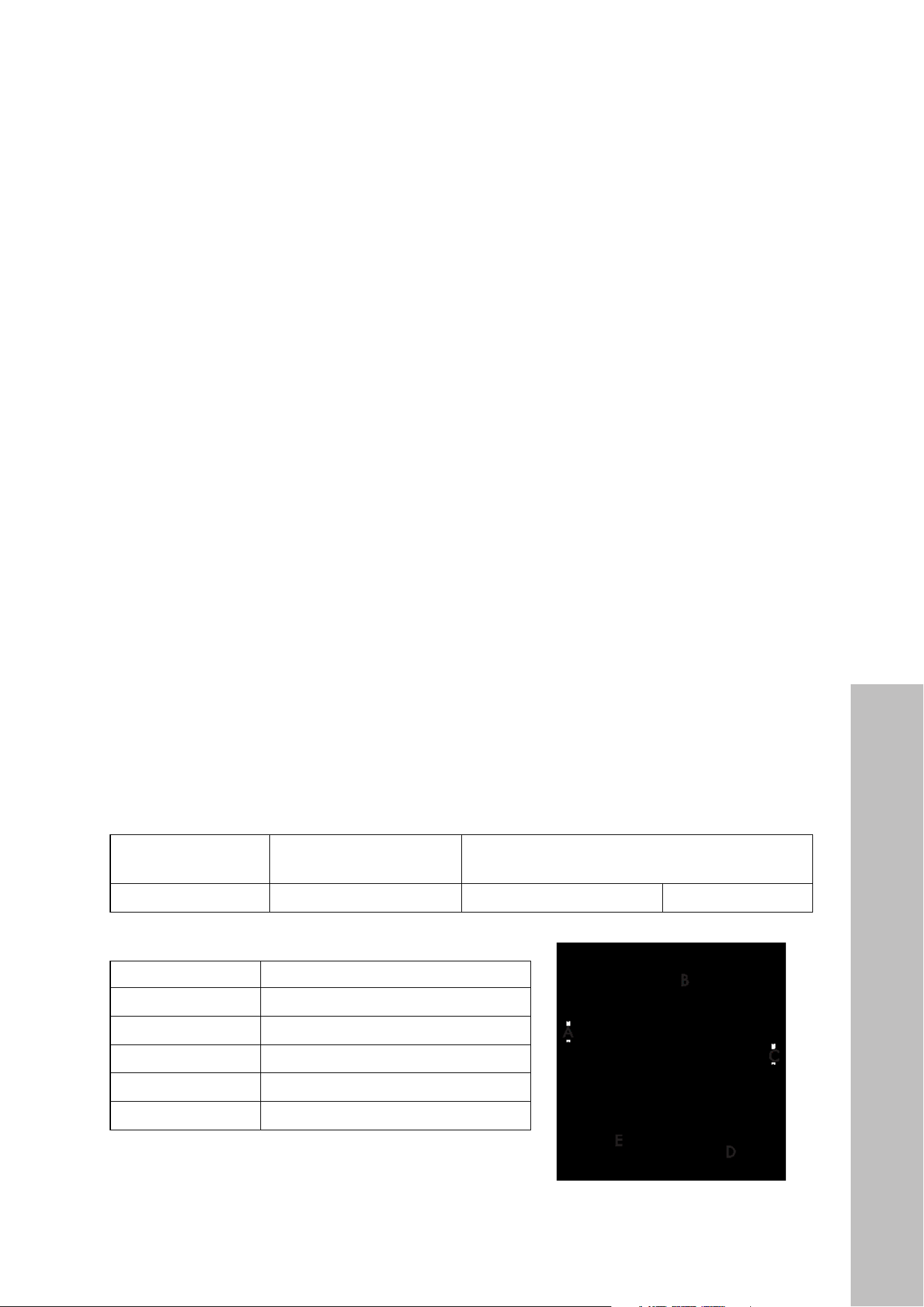
Product Specifications
BEFORE INSTALLATION
PRODUCT SPECIFICATIONS
A. Cooling Vents
B. Broil Element
C. Control Panel
D. Halogen Light
E. Convection Fan and
Element
F. Bottom Element (not
visible)
G. Appliance Tag Location
H. Door Gasket
I. Temperature Probe
J. Oven Rack (1)
K. Telescoping Oven Rack (1)
L. Broiler Pan
M. Broiler Pan Tray
N. Air Fry Basket
OVEN PRODUCT DIMENSION
ELECTRICAL RATING AND MAXIMUM
CONNECTED LOAD AT 240 VOLTS 60 HZ
Single Built-In Oven 30" (762 cm) wide 20 Amp 4800 Watts
LETTER TECHNICAL DIMENSIONS
A 28 5/8" (727 mm) Height (overall)
B 28 5/8" (727 mm) Width (recessed)
C 27 5/16" (694 mm) Height (recessed)
D* 23 1/2" (597 mm) Depth (recessed)
E 29 7/8" (759 mm) Width (overall)
*From back of unit to cabinet face. The full depth of the
unit, including the front frame, is 24 1/2" (610 mm).
Full depth including the handle is 27 1/2" (699 mm).

5
Tools
BEFORE INSTALLATION
TOOLS AND PARTS
Gather the required tools before starting installation. Read and follow the instructions
provided with any tools listed here.
TOOLS NEEDED
• Measuring Tape
• Straightedge
• Pencil or Marker
• Phillips-head Screwdriver
• Level
• Wire Cutters and Wire Stripper
• Hand or Sabre Saw
• 1" Hole Saw
• Cordless Drill and 1/8" Drill Bit
• Safety Gloves and Goggles
• Volt Meter (0-250VAC)
PARTS NEEDED
• UL Listed Conduit Connector
• UL Listed Wire Connectors
PARTS PROVIDED
• #8-14 x 1" Screws (2)

6
Electrical Connection
BEFORE INSTALLATION
ELECTRICAL REQUIREMENTS
ELECTRIC SHOCK HAZARD
If codes permit and a separate ground wire is used, it is recommended that a qualified
electrical installer determine the ground path is adequate and wire gauge is in accordance
with local codes. Do not use an extension cord with this appliance; doing so may void the
warranty.
IN U�S�A�
Be sure the electrical connection and wire sizes are adequate and in conformance with the
National Electrical Code ANSI/NPA70-latest edition and all local codes and ordinances.
A hard copy of the above code standards can be obtained from:
National Fire Protection Association
One Batterymarch Park
Quincy, MA 02269
IN CANADA
Be sure the electrical connection and wire size are adequate and in conformance with
Canadian Electrical Code CSA standard C22.1, Part 1-latest edition, and all local codes
and ordinances. A hard copy of the above code standards can be obtained from:
Canadian Standards Association
178 Rexdale Blvd.
Toronto, ON M9W 1R3 CANADA
• The electrical power to the oven branch circuit must be shut off while line connections
are being made.
• A proper electrical ground is required on this appliance. The free end of the green
wire (the ground wire) must be connected to a suitable ground. This wire must remain
grounded to the oven.
• If a cold water pipe is interrupted by plastic, non-metallic gaskets, union connections,
or other insulating materials, DO NOT use for grounding.
• DO NOT ground to a gas pipe.
• DO NOT have a fuse in the NEUTRAL or GROUNDING circuit. A fuse in the
NEUTRAL or GROUNDING circuit could result in an electrical shock.
7
Electrical Connection
BEFORE INSTALLATION
• Check with a qualified electrician if you are in doubt as to whether the appliance is
properly grounded. Failure to do so could result in death, fire, or electric shock.
• To properly install your oven, a qualified installer must determine the type of electrical
connection you will be using and follow the instructions provided for it here.
• The oven must be connected to the proper electrical voltage and frequency as
specified on the model number rating plate. The model number rating plate is located
on the appliance tag under the control panel on the oven. All models are dual rated,
and designed to be connected to 240VAC, 60Hz, 3-wire or 4-wire, single-phase
power supply.
• Install a suitable conduit box (not furnished). An appropriately sized UL conduit
connector must be used to correctly attach the conduit to the junction box.
• IMPORTANT: Local codes may vary; installation electrical connections and grounding
must comply with all applicable local codes.
• If local codes permit grounding through the neutral electrical supply, connect both
the white neutral wire and the green ground wire from the oven to the white neutral
electrical supply wire.
• When only a 4-wire, single-phase, 240VAC, 60Hz-only electrical supply is available,
a 25-amp maximum circuit protection is required.
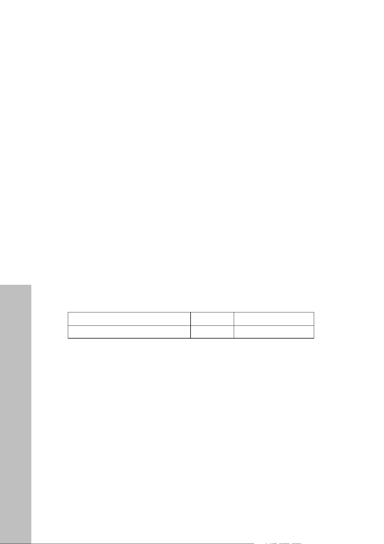
VOLTAGE AND FREQUENCY AMPS CIRCUIT REQUIRED
240VAC, 60Hz 20A 25 Amp Circuit

8
Pre-Installation Notes
BEFORE INSTALLATION
WARNING
This appliance shall be installed only by authorized persons and in accordance with the
manufacturer’s installation instructions, local gas fitting regulations, municipal building
codes, electrical wiring regulations, and/or local water supply regulations.
• Observe all governing codes and ordinances.
• Cabinet opening dimensions that are shown must be used. Given dimensions provide
minimum clearance with oven.
• Recessed installation area must provide complete enclosure around the recessed
portion of the oven.
• The oven support surface must be solid, level, and flush with the bottom of the cabinet
cutout.
• The oven support surface must be able to support the weight of 140 lb (65 kg) plus up
to 30 lb (14 kg) of food load.
• NOTE: For undercounter installation, it is recommended that the electrical junction box
be located in the adjacent right or left cabinet.
• To avoid damage to your cabinets, check with your builder or cabinet supplier to make
sure that the materials used will not discolor, delaminate, or sustain other damage.
This oven has been designed in accordance with the requirements of UL and CSA
International and complies with the maximum allowable wood cabinet temperatures of
194°F (90°C).
9
Cutout Dimensions
INSTALLATION
CUTOUT DIMENSIONS
Electrical Junction Box Location
NOTE: Junction box may be located in
adjacent cabinet
NOTE: The cabinet cutouts below allow for a minimal 1/4” (6 mm) gap for width and
height, or 1/8” (3 mm) on each side. These cutouts ensure appropriate space to mount the
unit into the cabinet cutout, as outlined on page 15.
LETTER DESCRIPTIONS UNDERCOUNTER WITHOUT COOKTOP OVEN IN CABINET
A Width (cutout) 28 7/8" (733 mm) 28 7/8" (733 mm)
B Height (cutout) 27 9/16" (700 mm) 27 9/16" (700 mm)
C Depth (cutout) 24" (610 mm) 24" (610 mm)
D Top of Cutout to Bottom of Upper Cabinet Door N/A 1 1/2" (38 mm)
E Bottom of Cutout to Floor (recommended)* 5 1/4" (133 mm) 32" (813 mm)
F Bottom of Cutout to Top of Cabinet Door N/A 1 1/2" (38 mm)
STEP 1 - UNPACK THE OVEN
EXCESSIVE WEIGHT HAZARD: Use two or more people to move and install the oven,
which weighs roughly 140 lb (65 kg). Failure to do so can may result in injury.
1. Using two or more people, remove the oven and set it on cardboard to avoid floor
damage. NOTE: Do not use the handle or any portion of the front frame for lifting.
2. Remove the shipping materials and tape from the oven.
3. Remove the hardware package from inside the bag containing this manual.
4. Remove and set aside racks and other parts from inside the oven.
5. Move the oven on the cardboard near where it will be installed.
10
Removing the Oven Door
INSTALLATION
WARNING
The oven doors are heavy and fragile, and the door front is glass. To avoid oven
door glass breakage, use both hands and grasp only the sides of the oven door
to remove.
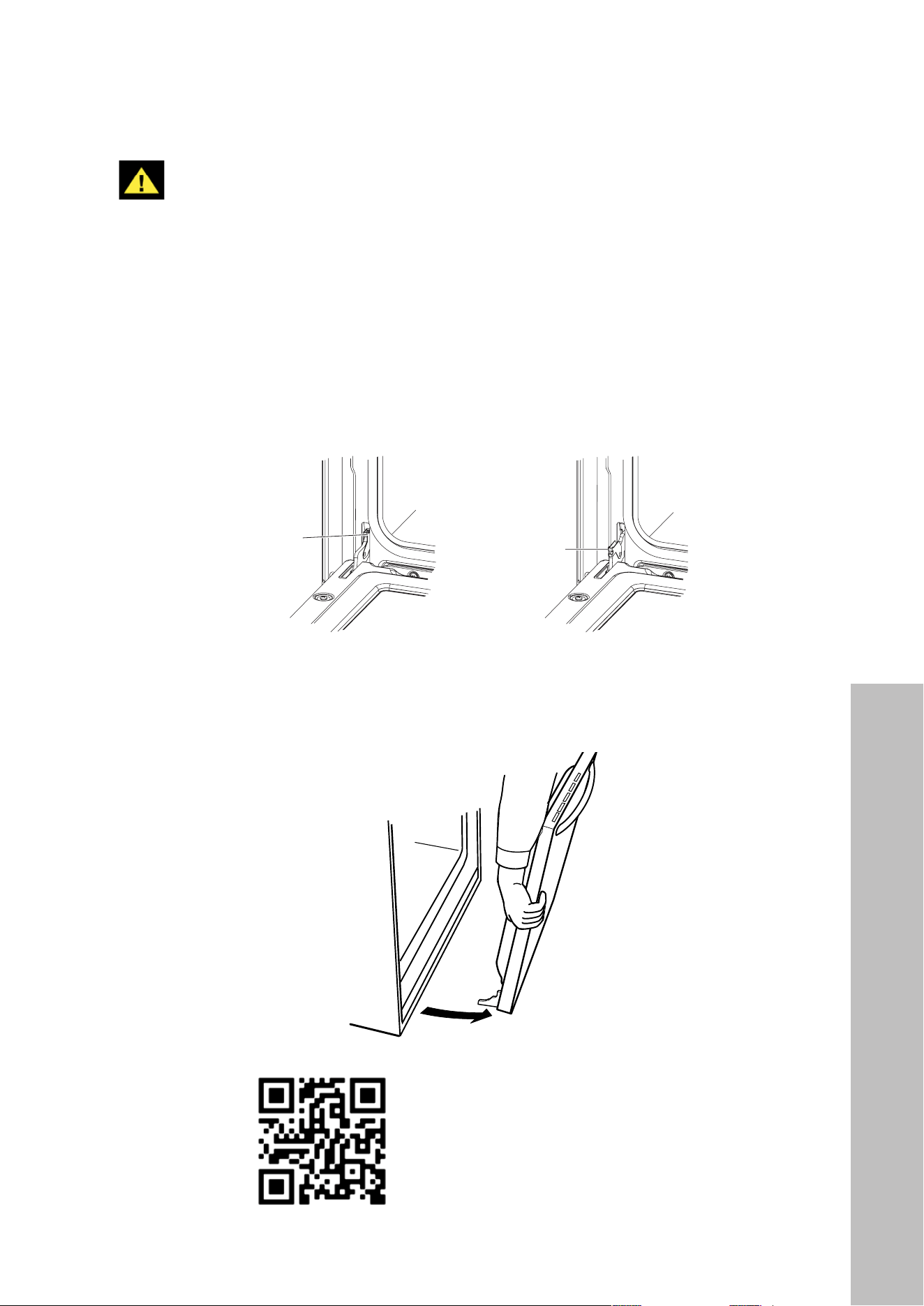
STEP 2 - REMOVE THE OVEN DOOR
1. Open the oven door.
2. Locate the door latches in both corners of the oven door and rotate the latches forward
from the locked position (below left) to the unlocked position (below right).
6E
INSTALLATION INSTRUCTIONS
IMPORTANT: This appliance shall be installed only by authorized
persons and in accordance with the manufacturer’s installation
electrical wiring regulations, local water supply regulations.
STEP 1 - UNPACK THE OVEN
WARNING
EXCESSIVE WEIGHT HAZARD
Use two or more people to move and install oven.
Failure to do so can result in back or other injury.
1 Using two or more people, remove the oven and set it on cardboard
NOTE: Do not use the handle or any portion of the front frame
for lifting.
2 Remove the shipping materials and tape from the oven.
3 Remove the hardware package from inside the bag containing
literature.
4 Remove and set aside racks and other parts from inside the oven.
5 Move the oven on the cardboard near where it will be installed.
STEP 2 - REMOVE THE OVEN DOOR
IMPORTANT: The oven door is heavy and fragile, and the door
front is glass. To avoid oven door gl
ass breakage, use both hands,
and grasp only the sides of the oven door to remove.
1 Open the oven door.
2 Locate the door latches in both corners of the oven door, and rotate
the latches forward to the unlocked position.
Locked
Unlocked
3 Grasp the edges of the oven door with both hands and push the
oven door fully closed. Lift up and pull oven door toward you to
remove. Set the oven door(s) aside on a covered work surface.
STEP 3 - INSTALL OVEN
WARNING
EXCESSIVE WEIGHT HAZARD
Use two or more people to move and install oven.
Failure to do so can result in back or other injury.
1 Using two or more people, grasp the ceiling of the oven cavity and
lift the oven onto a table or platform even with the cutout opening.
NOTE: The surface must be able to support the following weight:
• Single Oven: 160 lb (73 kg)
• Double Oven: 290 lb (132 kg)
2
junction box.
6E
INSTALLATION INSTRUCTIONS
IMPORTANT: This appliance shall be installed only by authorized
persons and in accordance with the manufacturer’s installation
electrical wiring regulations, local water supply regulations.
STEP 1 - UNPACK THE OVEN
WARNING
EXCESSIVE WEIGHT HAZARD
Use two or more people to move and install oven.
Failure to do so can result in back or other injury.
1 Using two or more people, remove the oven and set it on cardboard
NOTE: Do not use the handle or any portion of the front frame
for lifting.
2 Remove the shipping materials and tape from the oven.
3 Remove the hardware package from inside the bag containing
literature.
4 Remove and set aside racks and other parts from inside the oven.
5 Move the oven on the cardboard near where it will be installed.
STEP 2 - REMOVE THE OVEN DOOR
IMPORTANT: The oven door is heavy and fragile, and the door
front is glass. To avoid oven door gl
ass breakage, use both hands,
and grasp only the sides of the oven door to remove.
1 Open the oven door.
2 Locate the door latches in both corners of the oven door, and rotate
the latches forward to the unlocked position.
Locked
Unlocked
3 Grasp the edges of the oven door with both hands and push the
oven door fully closed. Lift up and pull oven door toward you to
remove. Set the oven door(s) aside on a covered work surface.
STEP 3 - INSTALL OVEN
WARNING
EXCESSIVE WEIGHT HAZARD
Use two or more people to move and install oven.
Failure to do so can result in back or other injury.
1 Using two or more people, grasp the ceiling of the oven cavity and
lift the oven onto a table or platform even with the cutout opening.
NOTE: The surface must be able to support the following weight:
• Single Oven: 160 lb (73 kg)
• Double Oven: 290 lb (132 kg)
2
junction box.
Unlocked
Locked
3. Grasp the edges of the oven door with both hands and push the oven door fully
closed. Lift up and pull the door toward you to remove. Set the oven door aside on a
covered work surface.
6E
INSTALLATION INSTRUCTIONS
IMPORTANT: This appliance shall be installed only by authorized
persons and in accordance with the manufacturer’s installation
electrical wiring regulations, local water supply regulations.
STEP 1 - UNPACK THE OVEN
WARNING
EXCESSIVE WEIGHT HAZARD
Use two or more people to move and install oven.
Failure to do so can result in back or other injury.
1 Using two or more people, remove the oven and set it on cardboard
NOTE: Do not use the handle or any portion of the front frame
for lifting.
2 Remove the shipping materials and tape from the oven.
3 Remove the hardware package from inside the bag containing
literature.
4 Remove and set aside racks and other parts from inside the oven.
5 Move the oven on the cardboard near where it will be installed.
STEP 2 - REMOVE THE OVEN DOOR
IMPORTANT: The oven door is heavy and fragile, and the door
front is glass. To avoid oven door gl
ass breakage, use both hands,
and grasp only the sides of the oven door to remove.
1 Open the oven door.
2 Locate the door latches in both corners of the oven door, and rotate
the latches forward to the unlocked position.
Locked
Unlocked
3 Grasp the edges of the oven door with both hands and push the
oven door fully closed. Lift up and pull oven door toward you to
remove. Set the oven door(s) aside on a covered work surface.
STEP 3 - INSTALL OVEN
WARNING
EXCESSIVE WEIGHT HAZARD
Use two or more people to move and install oven.
Failure to do so can result in back or other injury.
1 Using two or more people, grasp the ceiling of the oven cavity and
lift the oven onto a table or platform even with the cutout opening.
NOTE: The surface must be able to support the following weight:
• Single Oven: 160 lb (73 kg)
• Double Oven: 290 lb (132 kg)
2
junction box.
Scan to follow along with a video.
11
Installing the Oven
INSTALLATION
STEP 3 - INSTALL OVEN
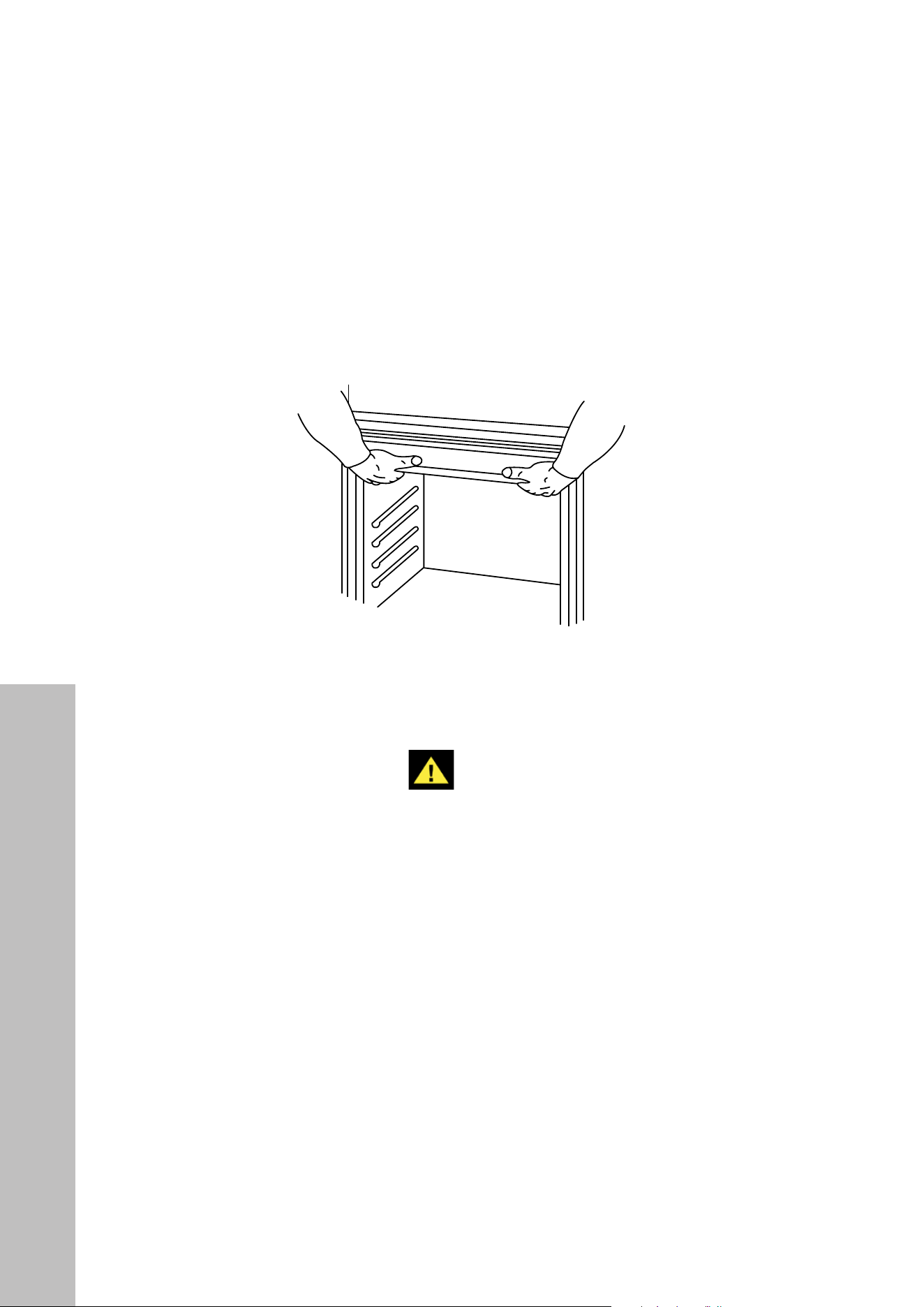
1. Using two or more people, grasp the ceiling of the oven cavity and lift the oven onto
a table or platform even with the cutout opening. NOTE: The surface must be able to
support up to 170 lb (77 kg).
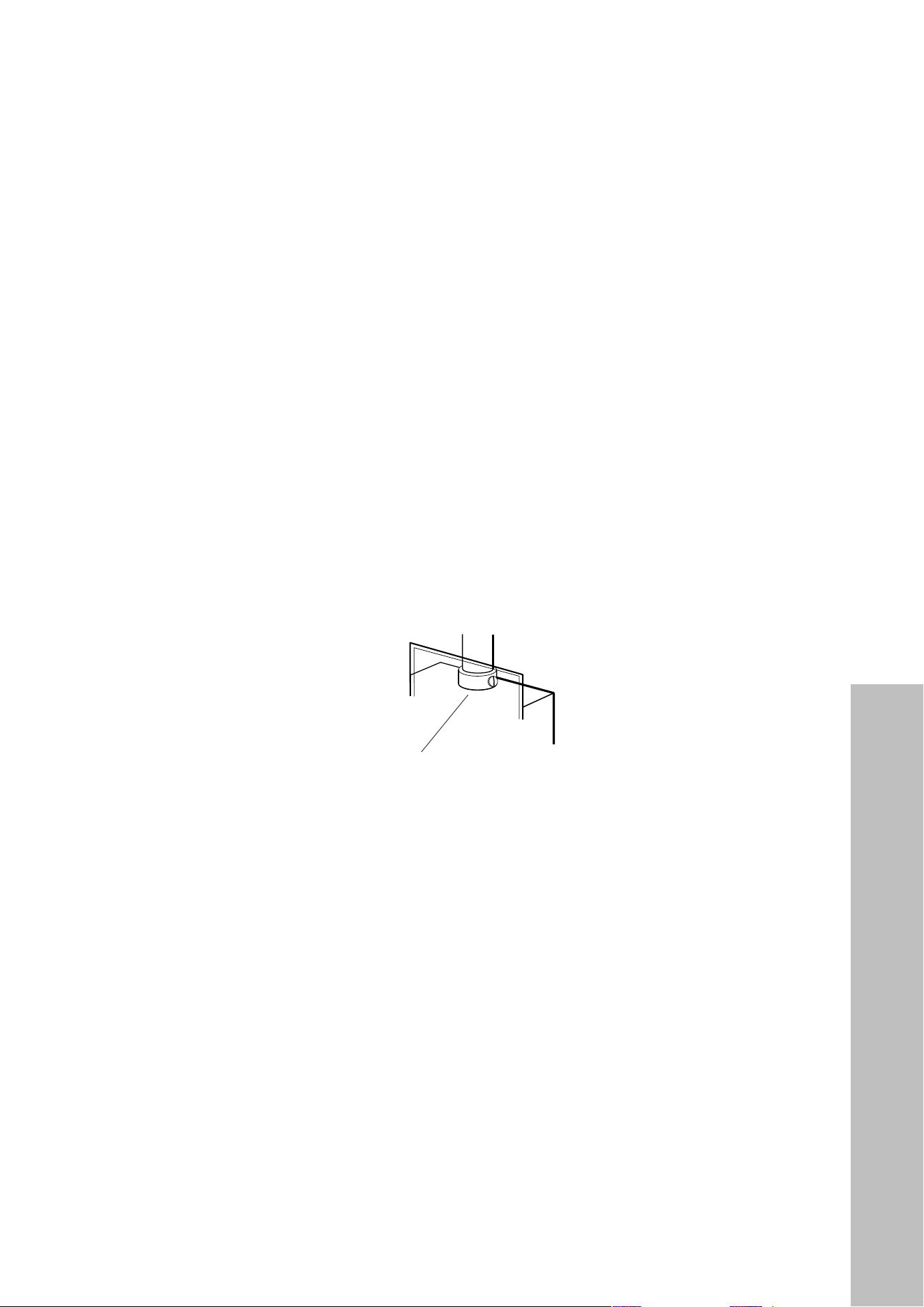
2. By hand, feed the flexible electrical supply conduit from the oven to the junction box
(Figure 1).
Figure 1
ELECTRICAL SHOCK HAZARD
WARNING
STEP 4 - ELECTRICAL GROUNDING INSTRUCTIONS
To properly install your oven, a qualified professional must determine the type of electrical
connection you will be using and follow the instructions provided for it here.
DIRECT WIRE
• Disconnect power before servicing.
• Improper connection of aluminum house wiring and copper appliance leads can result
in an electrical hazard or fire. If the home has aluminum wiring, only use UL listed
conduit connectors and wire connectors for joining copper to aluminum and precisely
follow the manufacturer’s recommended procedure. Aluminum-to-copper connections
must conform with local codes.
• Use 10-gauge copper or aluminum wire.
12
Electrical Connection
INSTALLATION
• Be sure your appliance is properly installed and grounded by a qualified technician;
failure to do so may result in death or electrical shock. Ask your dealer to recommend
a qualified technician or an authorized service provider.
• This oven is manufactured with a neutral (white) power supply wire and a cabinet
connected green (or bare) ground wire twisted together.
• After making sure that the power has been turned off, connect the flexible conduit from
the oven to the junction box using a UL listed conduit connector. The Grounded Neutral
and Ungrounded Neutral graphics on the following pages, along with the instructions
provided, present the most common way of connecting ovens. Your local codes and
ordinances, of course, take precedence over these instructions. Complete electrical
connections according to local codes and ordinances.
1. Disconnect power.
2. Remove junction box cover.
3. Install a UL listed or CSA approved conduit connector to the junction box.
E7
STEP 4 - MAKE ELECTRICAL
CONNECTION
To properly install your oven, you must determ ine the type of
electrical connection you wil l be using and follow the instructions
provided for it h ere.
DIRECT WIRE
WARNING
E L E CT R I CA L SHOCK H A Z AR D
Disconnect power before servicing.
Improper connection of aluminum house wiring and copper
appliance leads can result in an electrical hazard or re. If the
home has alum inum wiring, only use connectors designed and
UL listed for joining copper to alum inum and precisely follow
the manufacturer's recommended procedure. Alum inum-to-
Copper connections must conform with local codes.
For Single Oven, use 10
gauge copper or alum inum wire.
For Double Oven, use 8 gauge copper or alum inum wire.
E lectrically ground oven.
Failure to do so can result in death, re or electrical shock.
B e sur e your appliance is pr oper ly installed and gr ounded by a
techn ician or an author ized r epair ser vice.
T his oven is manufactured with a neutral (white) power supply wire
and a cabinetconnected green (or bare) ground wire twisted together.
A f ter making sure that the power has been turned of f, connect
listed conduit connector. T he Grounded Neutral and Ungrounded
Neutral Graphics on the following pages and the instructions
provided, present the most common way of connecting ovens. Your
local codes and ordinances, of course, take precedence over these
instructions. Complete electrical connections according to local
codes and ordinances.
1 Disconnect power.
2 R emove junction box cover.
3 Install a UL listed or CSA approved conduit connector to the
junction box.
4
the junction box through a UL listed or CSA approved conduit
connector.
5 T ighten screws on conduit connector.
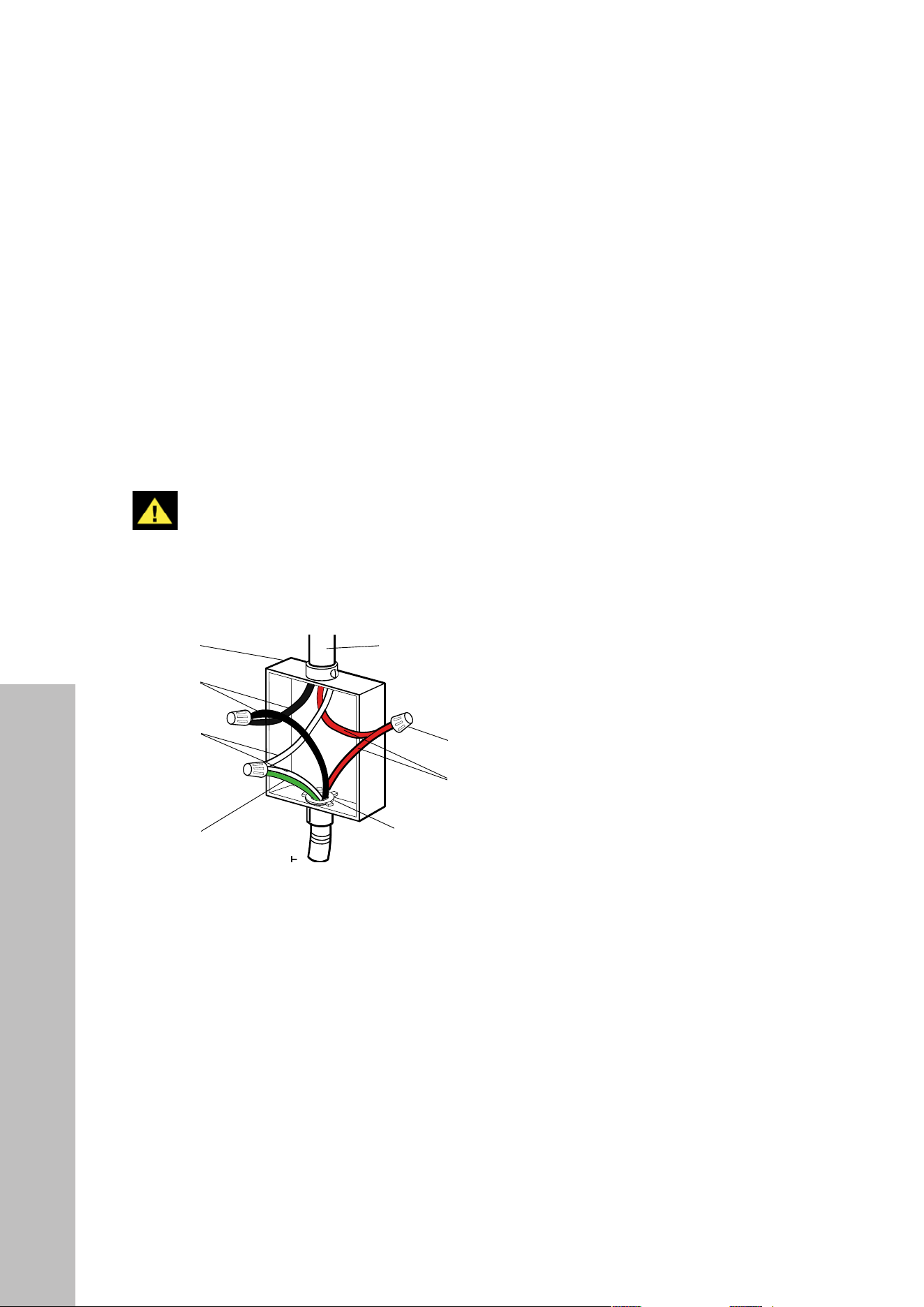
3-WIRE CONNECTION (GROUNDED NEUTRAL) -
U.S.A. ONLY
WARNING
E L E CT R I CA L SHOCK H A Z AR D
Grounding through the neutral conductor is prohibited for
new branch-circuit installations (1996 NE C); mobile homes;
and recreational vehicles, or in an area where local codes pro-
hibit grounding through the neutral conductor. For installations
where grounding through the neutral conductor is prohibited,
see the Ungrounded Neutral graphic.
Use grounding term inal or lead to ground unit.
Connect neutral
terminal or lead to branch circuit neutral in
usual manner.
3-WIR E CAB L E F R OM HOME P OWE R S UPP L Y
I MP OR T ANT : Use the 3-wire cable from home power supply where
local codes perm it a 3-wire connection.
1 Disconnect power.
Grounded Neutral
E
I
G
H
F
A
B
C
D
A. Junction Box
B. Black Wires
C. Neutral (White) Wires
D. Ground (Green or
Bare) Wire
E. Cable from Oven
F. UL Listed Conduit
Connector
G. Red Wires
H. UL Listed Wire
Connectors
I. House Electrical
Supply
2 Connect the two black wires B together using a UL listed wire
connector.
3 Connect the two neutral (white) wires C and the ground (green or
bare) wire d (of the oven cable) using a UL listed wire connector.
4 Connect the two red wires G together using a UL listed wire
connector.
5 Install junction box cover.
UL or CSA Listed Conduit Connector
4. Route the flexible electrical supply conduit from the oven to the junction box through a
UL listed or CSA approved conduit connector.
5. Tighten screws on conduit connector.
13
3- Wire Connection
INSTALLATION
3-WIRE CONNECTION (GROUNDED NEUTRAL) - U�S�A� ONLY
• Grounding through the neutral conductor is prohibited for new branch-circuit
installations (1996 NEC); mobile or manufactured homes; and recreational vehicles,
or in an area where local codes prohibit grounding through the neutral conductor.
For installations where grounding through the neutral conductor is prohibited, see the
Ungrounded Neutral graphic on the next page.
• Use a grounding terminal or lead to ground unit. Connect neutral terminal or lead to
neutral branch circuit in usual manner.
• Failure to follow these directions could result in death, fire, or electric shock.
3-WIRE CABLE FROM HOME ELECTRICAL SUPPLY
WARNING
Only use the 3-wire cable from home electrical supply where local codes
permit a 3-wire connection.
1.
E7
STEP 4 - MAKE EL ECTRICAL
CONNECTION
To properly install your oven, you must determ ine the type of
electrical connection you wil l be using and follow the instructions
provided for it here.
DIRECT WIRE
WARNING
E L E CT R I CAL SHOCK H AZ A R D
Disconnect power before servicing.
Improper connection of alum inum house wiring and copper
appliance leads can result in an electrical hazard or re. I f the
home has alum inum wiring, only use connectors designed and
UL listed for joining copper to alum inum and precisely follow
the manufacturer's recom mended procedure. A lum inum- to-
Copper connections must conform with local codes.
For Single Oven, use 10
gauge copper or aluminum wire.
For Double Oven, use 8 gauge copper or aluminum wire.
E lectrically ground oven.
Failure to do so can result in death, re or electrical shock.
B e su r e your appliance is pr oper ly insta lled and gr ounded by a
techn ician or an aut hor ized r epair ser vice.
T his oven is manufactured with a neutral (white) power supply wire
and a cabinetconnected green (or bare) ground wire twisted together.
A f ter mak ing sure that the power has been turned off, connect
listed conduit connector. T he Grounded Neutral and Ungrounded
Neutral Graphics on the following pages and the instructions
provided, present the most com mon way of connecting ovens. Your
local codes and ordinances, of course, take precedence over these
instructions. Complete electrical connections according to local
codes and ordinances.
1 Disconnect power.
2 R emove junction box cover.
3 I nstall a UL listed or CSA approved conduit connector to the
junction box.
4
the junction box through a UL listed or CSA approved conduit
connector.
5 T ighten screws on conduit connector.
3-WIRE CONNECTION (GROUNDED NEUTRAL) -
U.S.A. ONLY
WARNING
E L E CT R I CAL SHOCK H AZ A R D
Grounding through the neutral conductor is prohibited for
new branch-circuit installations (1996 NE C); mobile homes;
and recreational vehicles, or in an area where local codes pro-
hibit grounding through the neutral conductor. For installations
where grounding through the neutral conductor is prohibited,
see the Ungrounded Neutral graphic.
Use grounding terminal or lead to ground unit.
Connect neutral
term inal or lead to branch circuit neutral in
usual manner.
3-WIR E CAB L E F R OM HOME P OWE R S UPP L Y
I MP OR T ANT : Use the 3-wire cable from home power supply where
local codes perm it a 3-wire connection.
1 Disconnect power.
Grounded Neutral
E
I
G
H
F
A
B
C
D
A. Junction Box
B. Black Wires
C. Neutral (White) Wires
D. Ground (Green or
Bare) Wire
E. Cable from Oven
F. UL Listed Conduit
Connector
G. Red Wires
H. UL Listed Wire
Connectors
I. House Electrical
Supply
2 Connect the two black wires B together using a UL listed wire
connector.
3 Connect the two neutral (white) wires C and the ground (green or
bare) wire d (of the oven cable) using a UL listed wire connector.
4 Connect the two red wires G together using a UL listed wire
connector.
5 I nstall junction box cover.
UL or CSA Listed Conduit Connector
A. Junction Box
B. Black Wires
C. Neutral (White) Wires
D. Ground (Green or Bare) Wire
E. Cable from Oven
F. UL Listed Conduit Connector
G. Red Wires
H. UL Listed Wire Connectors
I. Home Electrical Supply
Grounded Neutral
A
B
C
D
E
F
H
I
G
Disconnect power.
2. Connect the two black wires (B) together using a UL listed wire connector.
3. Connect the two neutral (white) wires (C) and the ground (green or bare) wire (D) (of
the oven cable) using a UL listed wire connector.
4. Connect the two red wires (G) together using a UL listed wire connector.
5. Install junction box cover.
14
4-Wire Connection
INSTALLATION
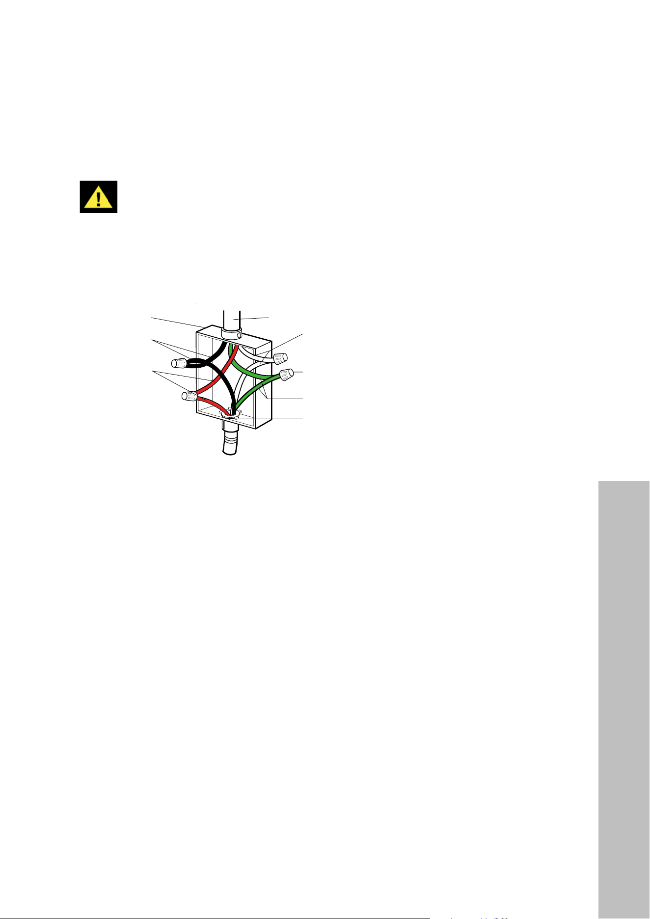
4-WIRE CONNECTION (UNGROUNDED NEUTRAL) - U�S�A� AND CANADA
4-WIRE CABLE FROM HOME ELECTRICAL SUPPLY
WARNING
Use the 4-wire cable from home electrical supply in the U.S. where local codes
do not allow grounding through neutral, new branch circuit installations (1996
NEC), mobile and manufactured and recreational vehicles, new construction,
and in Canada.
1.
8E
4-WIRE CONNECTION (UNGROUNDED NEUTRAL) -
U.S.A. AND CANADA
4-WIRE CABLE FROM HOME POWER SUPPLY
IMPORTANT: Use the 4-wire cable from home power supply in
the U.S. where local codes do not allow grounding through neutral,
New Branch circuit installations (1996 NEC), mobile homes and
recreational vehicles, new construction and in Canada.
1 Disconnect power.
I
A. Junction Box
B. Black Wires
C. Red Wires
D. Cable from Oven
E. UL listed or CSA
Approved Conduit
Connector
F. Ground (Green or
Bare) Wires
G. UL Listed Wire
Connector
H. Neutral (White) Wires
I. House Electrical
Supply
Ungrounded Neutral
B
C
D
G
F
E
H
A
2 Connect the 2 black wires B together using a UL listed wire
connector.
3 Connect the 2 red wires C together using a UL listed wire
connector.
4 Untwist white wire from green (or bare) ground wire coming
from the oven.
5 Connect the 2 neutral (white) wires H together using a UL listed
wire connector.
6 Connect the ground (green or bare) wire FA from the oven cable
to the ground (green or bare) wire (in the junction box)
using a
UL listed wire connector.
7 Install junction box cover.
STEP 5 - MOUNT THE OVEN
1 Slide the oven completely into the cabinet until the back surface
of the front frame touches the front wall of the cabinet. Center
the oven within the cabinet cutout.
NOTE: Push against seal area of the oven front frame when push-
ing the oven into the cabinet. Do not push against the outside edges.
Mounting Frame
Mounting Frame Hole
2 There are two holes, one on each side of the front frame that sur-
rounds the oven cavity. Drill 1/8" (3.18 mm) pilot holes through
the holes, and into the front wall of the cabinet.
NOTE: The double oven has four mounting holes, two on each
side.
3 Insert the # 8–14 x 1" screws (provided) through the pilot holes to
securely fasten the oven to the cabinet. Do not overtighten screws.
4 Replace the oven racks.
NOTE: Ensure all plastic and foam packaging are removed from
the oven racks before r
einserting them.
5 Reconnect power to the oven.
STEP 6 - REPLACE THE DOOR
IMPORTANT: The oven door is heavy and fragile, and the door
front is glass. To avoid oven door glass breakage, use both hands,
and grasp only the sides of the oven door to remove.
1 Verify that the door hinge latches are forward, and then insert the
oven door hinges into the openings.
2 Lower the oven door to engage the hinges.
3 Press the hinge latches down to lock.
STEP 7 - COMPLETE INSTALLATION
1 Check that all parts are now installed. If there is an extra part, go
back through the steps to see which step was skipped.
2 Dispose of/recycle all packaging materials.
3 Check Operation of Oven.
• Turn on power.
• Press BROIL.
• Set the temperature.
• Press START.
NOTE: If oven(s) does not operate, check the following:
• Household fuse is intact and tight; or circuit breaker has not
tripped.
• Electrical supply is connected.
• See “Troubleshooting” section in the Operation Manual.
4 When oven has been on for 5 minutes, feel for heat. If you do not
feel heat or if an error message appears in the display, turn off
5 Press STOP/CLEAR to turn off the oven.
IMPORTANT: For oven use and cleaning, read the User Manual.
Ungrounded Neutral
A. Junction Box
B. Black Wires
C. Red Wires
D. Cable from Oven
E. UL Listed or CSA Approved
Conduit Connector
F. Ground (Green or Bare) Wires
G. UL Listed Wire Connector
H. Neutral (White) Wires
I. Home Electrical Supply
A
B
C
D
E
F
H
I
G
Disconnect power.
2. Connect the 2 black wires (B) together using a UL listed wire connector.
3. Connect the 2 red wires (C) together using a UL listed wire connector.
4. Untwist white wire (H) from green (or bare) ground wire (F) coming from the oven.
5. Connect the 2 neutral (white) wires (H) together using a UL listed wire connector.
6. Connect the ground (green or bare) wire (F) from the oven cable to the ground (green
or bare) wire (in the junction box) using a UL listed wire connector.
7. Install junction box cover.
15
Mount the Oven
INSTALLATION
STEP 5 - MOUNT THE OVEN
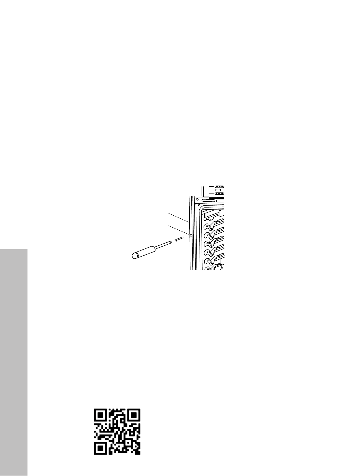
1. Slide the unit completely into the cabinet until the back surface of the front frame
touches the front wall of the cabinet. Center the oven within the cabinet cutout.
NOTE: Push against the seal of the oven’s front frame when pushing the unit into the
cabinet. Do not push against the outside edges.
2. There are two holes, one on each side of the front frame that surrounds the oven. Drill
1/8" pilot holes through the holes and into the front wall of the cabinet. There are two
mounting holes, one on each side.
3. Insert the #8–14 x 1" screws (provided) through the pilot holes to securely fasten the
oven to the cabinet (Figure 1). Do not overtighten screws.
A
B
C
Mounting frame
Figure 1
Mounting frame hole
4. Replace the oven racks. NOTE: Ensure all plastic and foam packaging is removed from
the oven racks before reinserting them.
5. Reconnect power to the oven.
STEP 6 - REPLACE THE DOOR
1. Verify that the door hinge latches are forward, and then insert the oven door hinges
into the openings.
2. Lower the oven door to engage the hinges.
3. Press the hinge latches down to lock.
Scan to follow along with a video.
16
Changing Handle
INSTALLATION
STEP 7 - COMPLETE INSTALLATION
1. Check that all parts are now installed. If there is an extra part, go back through the
steps to see which step was skipped.
2. Dispose of/recycle all packaging materials.
3. Check operation of oven:
• Turn on power.
• Press Broil.
• Set the temperature.
• Press Start.
NOTE: If oven(s) does not operate, check the following:
• Household fuse is intact and tight; or circuit breaker has not tripped.
• Electrical supply is connected.
• See the “Troubleshooting” section in the User Manual.
Scan to view the User Manual.
4. After the oven has been on for 5 minutes, feel for heat. If you do not feel heat or if
an error message appears in the display, turn off the oven and contact a qualified
technician.
5. Press Cancel to turn off the oven.
CHANGING HANDLE
To remove handle on the oven door, remove the screw and pull hand outward.
To install handle:
1. Screw in anchors to the door with a Phillips-head screwdriver.
2. Line up and fit the handle into the top and bottom door anchors.
3. Using an Allen/hex wrench, secure the top and bottom handle screws to the door
anchors.

COVERAGE
ZLINE Kitchen and Bath wall oven products will be warrantied for one year from the
original purchase date for the original purchaser of the product. This warranty covers all
parts for necessary repairs if any part of the product proves to be defective in materials or
workmanship.
TERMS
This warranty applies only to the original purchaser of a range product installed for
normal residential use. This is defined as a single-family, residential dwelling in a non-
commercial setting. Commercial settings include but are not limited to: schools, churches,
hotels, restaurants, vacation rentals such as Airbnb, day care centers, private clubs, fire
stations, common areas in multi-family dwellings, nursing homes, food service locations, and
institutional food service locations such as hospitals or correction facilities. This warranty is
non-transferable and will not be extended based on the date of installation. The warranty
applies only to products installed in the continental United States and the District of Columbia.
Warranty shall not apply and ZLINE Kitchen and Bath is not responsible for damage resulting
from negligence, improper maintenance, misuse, abuse, alteration of or tampering with the
appliance, accident, natural disaster, improper electric supply, flare-up fires, unauthorized
service or repair, improper installation, or installation not in accordance with the instructions
contained in the manual or local government codes.
WHAT IS NOT COVERED
1. Installation or start-up, damages or problems caused by improper installation or use.
2. Service by an unauthorized service providers or damage related to unauthorized service
or unauthorized parts.
3. Installation in any commercial or non-residential application.
4. Removal or re-installation cost.
5. Aesthetic damage, scratches, or natural wear caused by normal use.
6. Second-hand, open box products, or products purchased from an unauthorized retailer.
WARRANTY

WARRANTY
NOTE: Please write down the model
number and serial number of your
appliance. Both numbers are located on
the rating label. Do not remove
permanently affixed labels, warnings, or
plates from the product. This will void the
warranty. You may also consider
attaching your receipt or proof of
purchase to this manual.
SERVICE
For warranty service, please contact our Customer Service team at
1-614-777-5004 or visit www.zlinekitchen.com/contact to utilize
our online Customer Experience Portal.
Need to purchase a part or accessory for your ZLINE
product? Visit www.zlineparts.com, ZLINE’s official parts
distribution partner.