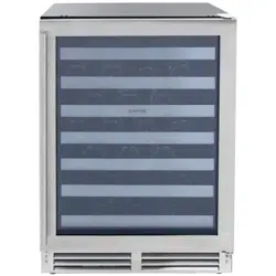
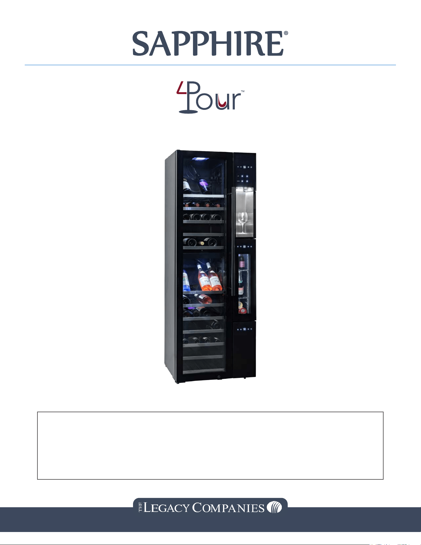
4-Pour Wine Bar Instruction Manual
SW643TZBLK
This manual contains important information regarding your unit. Please read this
manual thoroughly prior to equipment set-up, operation, and maintenance. Failure
to comply with regular maintenance guidelines outlined in this manual may void the
warranty. Waste products are treated by specialized companies, please do not discard
them by yourself.
3355 Enterprise Ave #160, Ft. Lauderdale, FL 33331 | 954.202.7419 | sapphireappliances.com
TABLE OF CONTENTS
Safety PrecautionsSafety Precautions 3
Specications Specications 5
Product DiagramProduct Diagram 6
Check your ProductCheck your Product 7
InstallationInstallation 7
How to Use:How to Use: 10
Correct Use and Machine MaintenanceCorrect Use and Machine Maintenance 14
CleaningCleaning 16
TroubleshootingTroubleshooting 16
AppendixAppendix 18
WarrantyWarranty 22
Note: The company reserves the design changes to the product. If the product you purchased is
incomplete to the product manual, do not change the performance and use, please use it with condence.
2 SW643TZBLK - 4-Pour Wine Bar
IMPORTANT SAFEGUARDS
Please thoroughly read these SAFETY PRECAUTIONS before operating the unit.
The purpose of the safety precautions in this manual is to ensure safe and correct use of the unit to minimize
risks that could cause serious damage and injury to you or other persons. The safety precautions are divided
into WARNINGS and CAUTIONS. Cases where improper handling of the unit could lead to death or serious
injury are listed under the “
WARNING” heading. However, the cases listed under the “
CAUTION”
heading could also lead to serious results. To ensure the safety, adhere strictly to both types of safety
precautions.
• Keep ventilation on openings, in the appliance enclosure or in the built-in structure, clear of
obstruction.
• This appliance is not intended for use by persons (including children) with reduced physical, sensory
or mental capabilities, or lack of experience and knowledge, unless they have been given supervision
or instruction concerning use of the appliance by a person responsible for their safety.
• Children should be supervised to ensure that they do not play with the appliance.
• This appliance can be used by children aged from 8 years and above and persons with reduced
physical, sensory or mental capabilities or lack of experience and knowledge if they have been given
supervision or instruction concerning use of the appliance in a safe way and understand the hazards
involved. Children shall not play with the appliance. Cleaning and user maintenance shall not be
made by children without supervision.
• If the supply cord is damaged, it must be replaced by the manufacturer, its service agent or similarly
qualied persons to avoid a hazard.
• The appliance shall be disconnected from its power source during cleaning or maintenance and when
replacing parts.
• Storage: During periods of inactivity or before storing, remove all beverages from the appliance,
disconnect it from the supply and clean the appliance and its accessories thoroughly. Keep the door(s)
of the appliance open, to allow all humidity to escape. Prop the door open with a piece of wood or
the like to prevent the door from closing completely. Like this, mold or bad smell can be prevented.
Store the appliance in a dry, protected environment, preferably at room temperature. To protect the
appliance from dust, cover it with a cloth that allows air circulation on the inside of the appliance. You
can also store the appliance in its original packaging. Keep the appliance out of reach of children.
• Regularly check the power plug and power cord for damage. If the supply cord is damaged, it must
be replaced by the manufacturer, its service agent or similarly qualied persons to avoid a hazard.
• Refrigerants must be evacuated and disposed of by a qualied specialist per federal and local
regulations before the appliance is scrapped. CAUTION: Please keep the appliance away from re or
similar glowing substances before you dispose of it. Please remove the door before you dispose of
the appliance.
• Component parts shall be replaced with like components to minimize the risk of possible ignition due
to incorrect parts.
• The appliance is to be installed per the Safety Standard for Refrigeration Systems, ANSI/ASHRAE 15.
• WARNING: Keep clear of obstructions on all ventilation openings in the appliance enclosure or in the
structure for building-in.
• WARNING: Do not use mechanical devices or other means to accelerate the defrosting process, other
than those recommended by the manufacturer.
• WARNING: Do not damage the refrigerant circuit.
• WARNING: Do not use electrical appliances inside the storage compartments of the appliance, unless
they are of the type recommended by the manufacturer.
• WARNING: The light must not be replaced by the user! If the light is damaged, contact the customer
helpline for assistance.
• WARNING: To avoid a hazard due to instability of the appliance, it must be xed per the instructions.
• WARNING: To reduce ammability hazards the installation of this appliance must only be carried out
by a suitably qualied person.
3Instruction Manual
Text set off by the exclamation mark ‘ ’ contains information that should be strictly adhered to.
After reading the instruction manual, store it in an easily accessible place where the user(s) of this
product can easily nd it.
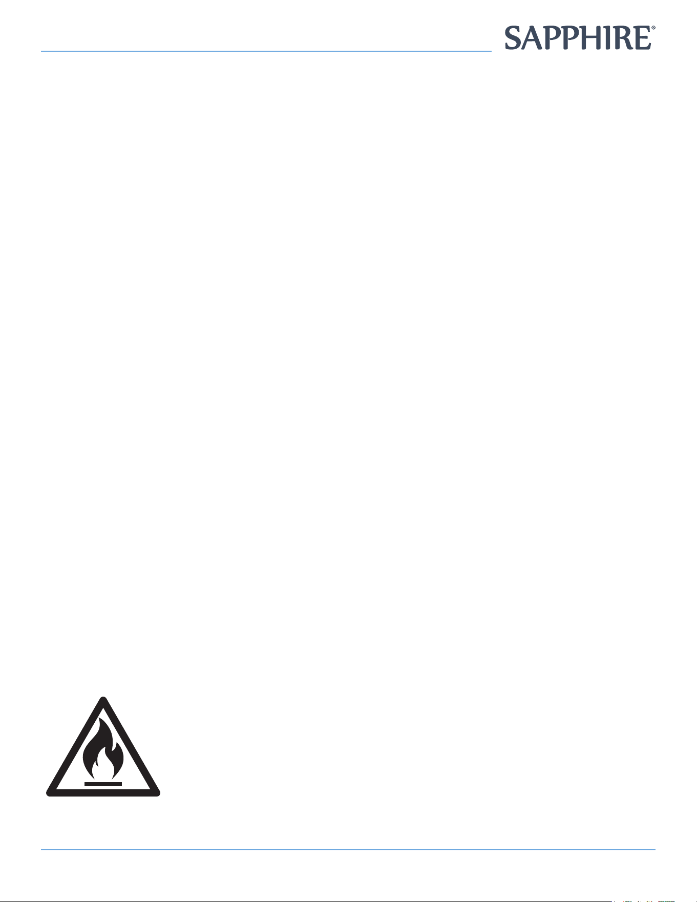
The symbol is a warning and indicates the refrigerant and insulation blowing gas are ammable.
WARNING: Risk of re / ammable materials.
WARNING
: Do not store explosive substances such as aerosol cans with a ammable propellant in
this appliance.
WARNING: When positioning the appliance, ensure the supply cord is not trapped or damaged.
WARNING
: Do not locate multiple portable socket-outlets or portable power supplies at the rear of
the appliance.
WARNING: The refrigerant and insulation blowing gas are ammable. When disposing of the appliance,
do so only at an authorized waste disposal center. Do not expose to ame.
PRECAUTIONS FOR INSTALLATION - WARNINGS:
Installation should be performed only by the dealer or a qualied expert. Attempting to install the unit
yourself could result in water leakage, refrigerant leakage, electrical shock, or re.
PRECAUTIONS FOR USE - WARNINGS:
All repairs, disassembly and modications should be performed only by qualied technicians.
Attempting to perform these tasks yourself could result in a re, malfunction, and injury.
Never splash water directly onto the product or wash with water as a short-circuit and electrical leakage
could result.
Never put ammable or volatile substances into the unit as an explosion and re could result.
Do not damage, modify, excessively bend, strain, twist or bundle up the power cord. Also, placing heavy
objects on the power cord or squeezing it in a tight place could damage it, possibly resulting in electrical
shock or re.
Use a dedicated wall outlet. Do not use extension cords or convenience receptacles as this could result
in electrical shock, overheating and a re.
Never use ammable spray cans or leave ammable substances near the unit. Sparks from electrical
switches could result in an explosion and re.
The cooler is intended for storage and display of beverages. Do not use for other purpose than intended
as this could adversely affect items placed in the unit.
Never attempt to insert ngers, sticks, etc. Into the cold air suction outlet, as a circulation fan is rotating at
high speed inside the outlet. Injury, electrical shock, and improper operation could result.
For indoor use only. Using the unit in a location exposed to rain could result in electrical leakage and
electrical shock.
Never place heavy objects or items containing water on top of the unit. Objects could fall and cause
injury, and spilled water could deteriorate the insulation of electrical components and result in
electrical leakage.
Install the unit in a location where the oor is sturdy enough to support the load of the unit. If the oor is
not sturdy enough or installation is incorrectly performed, the unit could tip over and the falling shelves
and products could cause personal injury.
WARNING: Improper handling of the unit could lead to death or serious injury.
CAUTION: Improper handling of the unit could lead to serious results depending on
the circumstances.
4 SW643TZBLK - 4-Pour Wine Bar
If you nd gas leakage, please don’t touch the appliance. Unplug the unit, open doors and windows for
ventilation. Refrigerant leakage could cause explosion, re, and re injury.
Store the unit in a location where it is not exposed to rain. Using a unit that has been exposed to rain
could result in electrical leakage and electrical shock.
Keep away from hot air sources, the cooling performance is reduced if the unit is placed near heat
sources such as hot plates and stoves, and if it is exposed to direct sunlight.
Leave disassembly and disposal of the unit to qualied experts.
Should the unit need temporary storage, make sure not to store the unit in a location where children
play and take precautions so that the door cannot be completely closed. This will minimize the risk that
a child becomes trapped inside the compartment.
WELL VENTILATED PLACE - Please make sure there is more than 10cm space between UPRIGHT
COOLER and the wall. If there is no space, cooling capacity can drop down.
If installation in a damp location is unavoidable, also install an electrical leakage circuit breaker. If no
electrical leakage circuit breaker is installed, electrical shock could result.
Never hang from the door or climb onto the unit. The unit could tip over or fall and cause material
damage or injury.
Before moving the unit, disconnect the power cord plug from the wall outlet, and make sure that the
power cord is not damaged during transport. A damaged power cord could result in electrical shock
and/or re.
Grasp the handle when closing the door. Holding at other positions could result in pinched ngers
and injury.
Do not push hand against or apply excessive force to glass surfaces as the glass could break and
cause injury.
When disconnecting the power cord plug from the wall outlet, hold at the plug main body close to the
outlet. Pulling the cord could cause wire breakage, possibly resulting in overheating and re.
Make sure that the unit does not tip over or fall when it is moved. A falling unit could cause serious
injury.
Do not throw items onto the shelves and do not place items totaling more than 40 lbs (20 kg) on each
shelf. The shelf could fall, possibly causing injury.
Be sure to attach and secure shelves correctly. An improperly attached shelf could fall and cause injury.
SPECIFICATIONS
Model SW643TZBLK
Volume of Wine Storage
(Zones 1 & 2)
6.9 cu. ft. (196L)
Volume of Argon Bottle
Chamber (Cylinder Chamber)
.7 cu. ft. (20L)
Volume of Beverage Cooler
(Zone 3)
.7 cu. ft. (20L)
Refrigerant / Amount
R600a / 1.34 oz
(38g)
Rated Voltage 110~120V~
Rated Frequency 60Hz
Max. Input Current 1.5A
High Side 250 PSI
Low Side 88 PSI
Insulation Agent Cyclopentane
5Instruction Manual
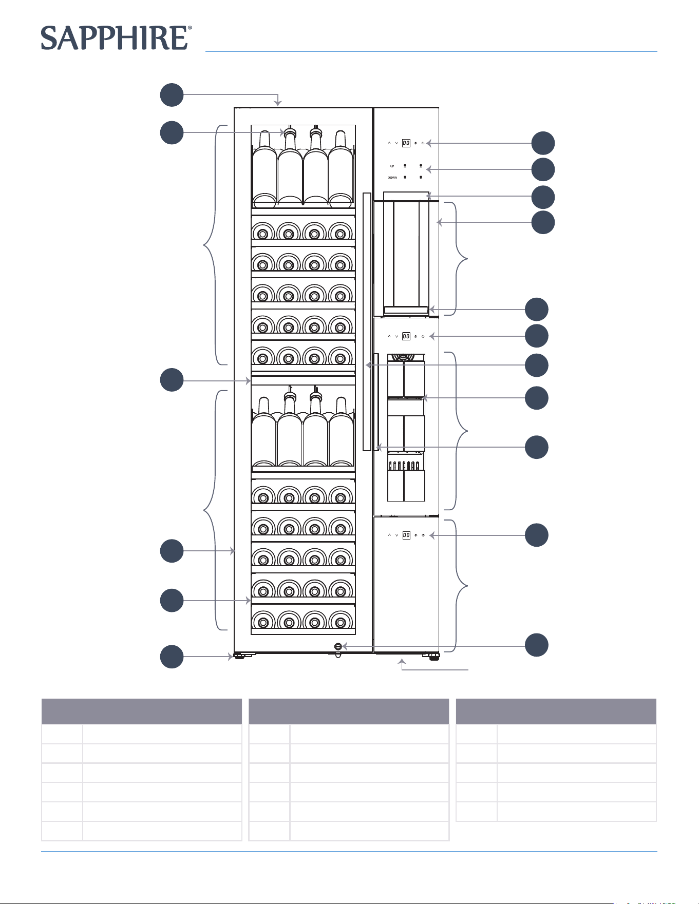
NO. DESCRIPTION
1 Leveling Leg
2 Shelf (12)
3 Glass Door
4 Divider
5 Cork (4)
6 Cabinet
NO. DESCRIPTION
7 Zone 1 Temperature Controls
8 Wine Dispenser Controls
9 Wine Dispensing Spout
10 Argon Bottle Chamber
11 Drip Tray
12 Zone 3 Control Panel
NO. DESCRIPTION
13 Door Handle
14 Shelf (3)
15 Right Middle Door Handle
16 Zone 2 Control Panel
17 Lock
PRODUCT DIAGRAM
3
Wine Storage
Zone 1
Wine Storage
Zone 2
Beverage Cooler
Zone 3
Wine Dispenser
Platform
2
1
4
5
6
Refrigeration
Unit
7
8
10
14
12
13
15
16
9
11
17
Hot Air Outlet
6 SW643TZBLK - 4-Pour Wine Bar
CHECK YOUR PRODUCT:
• Once you receive this product, please conrm that the package is intact, no defect in appearance, or
visual damages, etc.
• Open the door, check if the internal components and accessories are accounted for (such as shelves,
manual, etc.)
INSTALLATION:
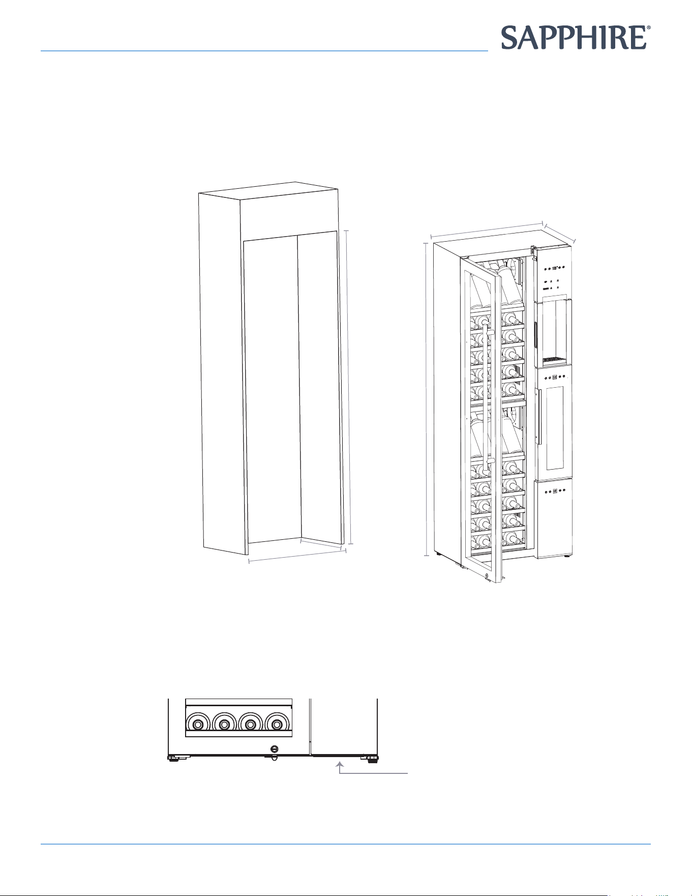
1. Carefully place
the machine in
the designated
spot, and ensure
that the place is
clean, level, and
sturdy.
26.57" (675 mm)
71.73"
(1822 mm)
15.9"
(405 mm)
72.04"-72.44"
(1830-1840 mm)
18.3"
(465 mm)
27.6"-27.95"
(700-710 mm)
2. Keep away from heat or high humid locations, such as laundry rooms
3. The angle cannot be greater than 45 degrees during handling. Do not lay or invert unit.
4. If unit is angled more than 45 degrees, you must wait for two (2) hours before it can be powered on.
5. Ensure that the local ventilation equipment is good, otherwise it will affect the efciency of the
machine.
6. Do not block airow around unit. Keep bottom unblocked, to prevent cooling problems.
As shown here:
Hot Air Outlet
7Instruction Manual
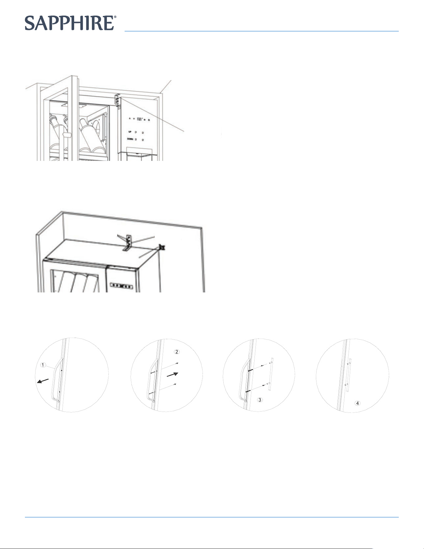
ANTI-TIP BUILT-IN INSTALLATION:
The installation of the Built-In Install Anti-Tip device is illustrated below:
Cabinet
Bracket Secured
with Screws
1. Place unit into the cabinet as shown in
the diagram
2. Afx bracket with screws as shown in
the diagram
3. The distance between the machine and
the wall on the left, right sides must be
at least 5/8" (15mm) the distance from
the top must be least 3/8" (10mm) the
distance from the back must be least
1-1/8" (30mm).
ANTI-TIP FREE STANDING INSTALLATION:
The installation of the Free-Standing, Anti-Tipping Brackets Anti-Tip in the is illustrated below
Screws
Wall
Mounting
Bracket
1. Place the unit ush against the wall
2. Take out the mounting bracket and screw
from the accessory plastic bag,
3. Afx the mounting bracket on the top of
the box,
4. Afx the other side on the wall, as shown
DOOR HANDLE INSTALLATION
Please follow the following four steps to install the door handle:
1. Remove door
gasket
2. Remove the door
handle, screws and
washers from the
door handle bag or
instructions
3. Insert screws into
pre-drilled holes.
Place washer on
exterior door
glass, and align
the handle. Secure
screws and handles
with screwdrivers.
4. Replace the door
gasket and make
sure it is installed
ush
8 SW643TZBLK - 4-Pour Wine Bar
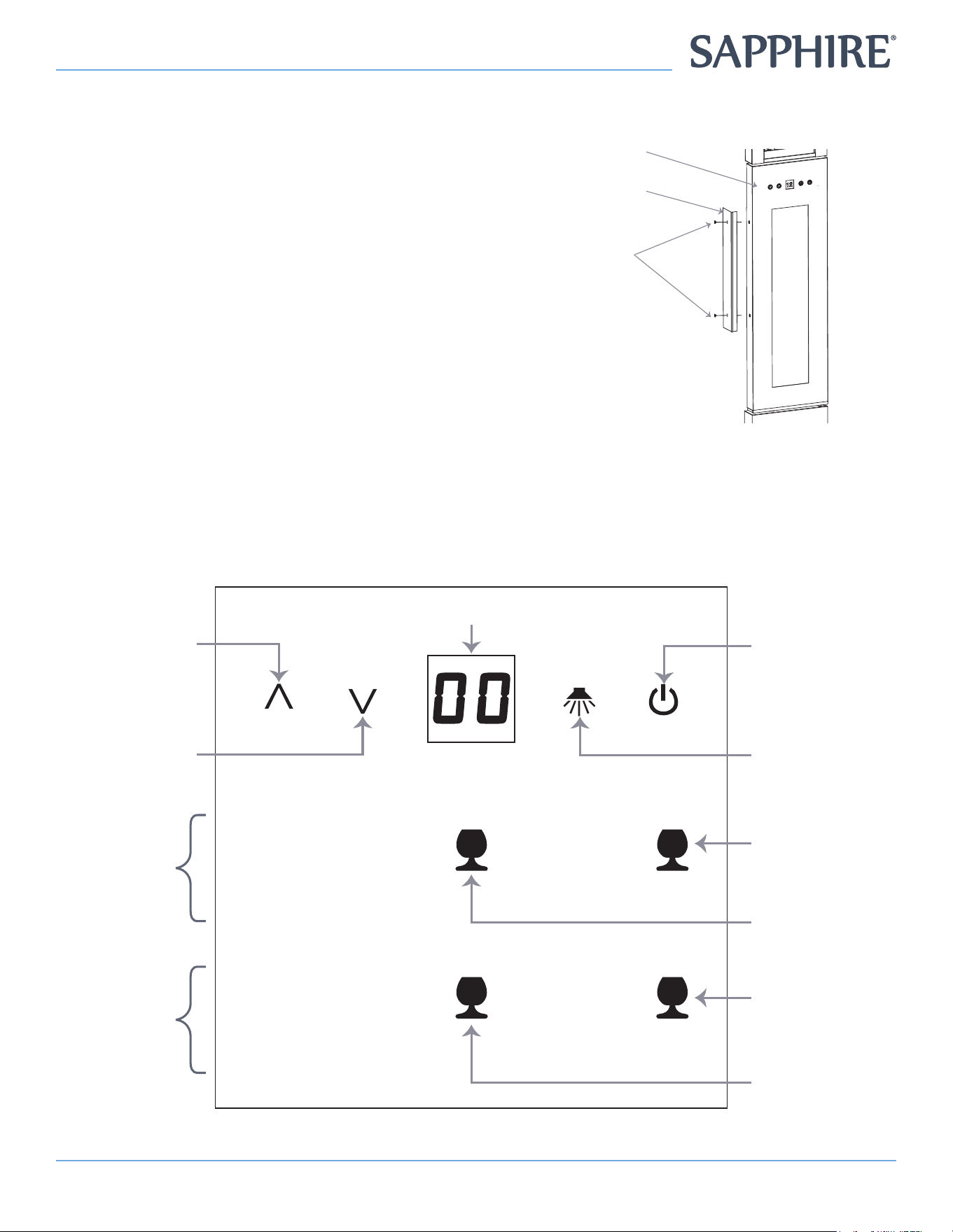
BEVERAGE COOLER DOOR HANDLE INSTALLATION
Please install the door handle according to the following diagram:
Place the handle as shown on the door body, align the
mounting holes with the holes on the door body, and
then x the screws with a manual screwdriver.
Door Body
Handle
Self-Tapping
Screws
Make sure the voltage is 110V/60Hz, and check if each area functions properly:
1. Test power, lights and temperature of each zone. Check the buttons are sensitive and there is no
abnormal phenomenon.
2. Open each cabinet, check if the compressor and the lamp function normal.
3. Check the operation of the lock and key.
CONTROL PANEL
UP
DOWN
Temperature
Increase
Temperature
Decrease
Zone 1
Wine
Dispenser
Controls
Power
On/Off
Light
On/Off
Zone 2
Wine
Dispenser
Controls
Zone 1
Left Bottle
Pour Control
Zone 2
Left Bottle
Pour Control
Zone 1
Right Bottle
Pour Control
Zone 2
Right Bottle
Pour Control
Temperature
9Instruction Manual
HOW TO USE
Temperature Settings
Option 1
• Wine Storage (Zone 1 and Zone 2) -
Temperature Setting Range: 50°F~ 65°F (10°C ~ 18.3°C)
• Beverage Cooler (Zone 3) -
Temperature Range: 38°F~ 65°F (3.3°C~ 18.3°C)
Option 2
• Wine Storage (Zone 1 and Zone 2) -
Temperature Setting Range: 41°F~ 72°F (5°C ~ 22°C)
• Beverage Cooler (Zone 3) -
Temperature Range: 33°F~ 72°F (1°C~ 22°C)
UP
DOWN
Temperature
Increase
Temperature
Decrease
Zone 1
Wine
Dispenser
Controls
Power
On/Off
Light
On/Off
Zone 2
Wine
Dispenser
Controls
Zone 1
Left Bottle
Pour Control
Zone 2
Left Bottle
Pour Control
Zone 1
Right Bottle
Pour Control
Zone 2
Right Bottle
Pour Control
Temperature
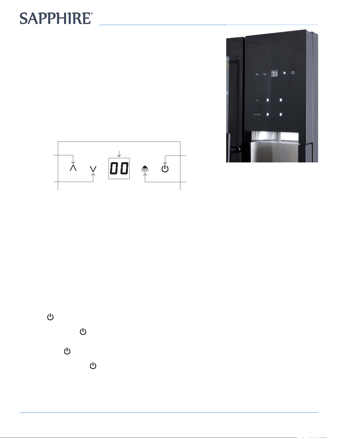
Preferred storage zone temperatures can be pre-set and saved.
• Each time the button is pressed, the temperature will increase or decrease 1 degree.
• To set the temperature, hold down the key.
• If it is not set within 5 seconds, the system will automatically return to the original setting. If the
temperature sensor is faulty, the digital management will display the E3 symbol.
To change between Celsius and Fahrenheit:
• Press and hold the Beverage Cooler (Zone 3) control panel by pressing the Temperature Increase
and Decrease buttons with two ngers at the same time for about 3 to 5 seconds.
Turn the sound ON or OFF:
• The sound is default set to ON.
• You can turn the sound ON or OFF by simultaneously pressing and holding the upper wine cooler
(Zone 1) Temperature Increase and Decrease buttons for 3 seconds
Power
• The Power Button of Zone 1 (Upper Wine Storage) is the power switch that controls the whole
unit, it is a Master Power Switch.
• Touch and hold Power button for 3 seconds to turn the unit ON/OFF.
Standby Mode
• Touch the Power button once to make the unit enter/exit Standby Mode.
• In Standby Mode, the wine dispensing function is still operable.
• You must touch the Power button of the other zones to turn them ON. This way, you can use each
zone separately.
Note: In Standby Mode, only the zone you turn on will work, the other zones are still in
Standby Mode.
10 SW643TZBLK - 4-Pour Wine Bar
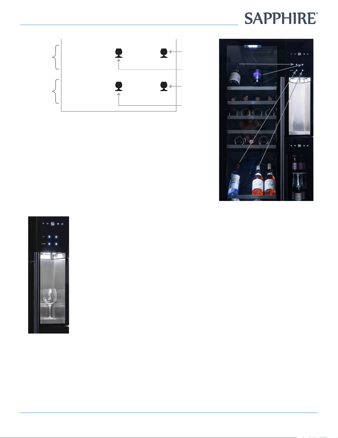
Wine Dispenser Controls:
UP
DOWN
Temperature
Increase
Temperature
Decrease
Zone 1
Wine
Dispenser
Controls
Power
On/Off
Light
On/Off
Zone 2
Wine
Dispenser
Controls
Zone 1
Left Bottle
Pour Control
Zone 2
Left Bottle
Pour Control
Zone 1
Right Bottle
Pour Control
Zone 2
Right Bottle
Pour Control
Temperature
• ‘UP’ corresponds to Zone 1 Wine Storage
• ‘DOWN’ corresponds to Zone 2 Wine Storage
• The Wine Glass Icons correspond to the bottles that are corked
in the top rack of each zone.
Wine Pouring Operation:
• Align the wine glass to the dispenser, press the corresponding wine button
• Each press of the dispenser button will dispense about 1.7oz (50mL) of
the wine.
• If the dispense button is held down it will dispense continuously.
Bottle Cork Operation:
• De-cork / open the wine bottle
• Put the plug and tube into the mouth of the wine bottle
• Adjust the length of the tube to t the depth of the bottle while holding the plug secure by pushing
or pulling tube
• Place bottle on shelf at an angle with the top of the bottle leaning against the support
11Instruction Manual
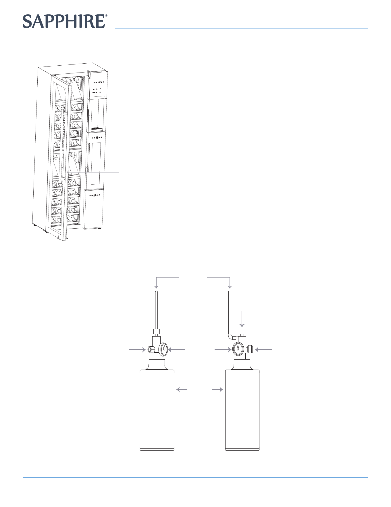
CYLINDER OPERATION
How to open the Argon Bottle Chamber:
Door handle to
Argon Bottle
Chamber
Glass Door
• Open the glass door to see the handle for the Argon
gas cylinder room.
• Pull door handle to open the Argon gas cylinder room.
CYLINDER OPERATION DIAGRAM:
Main
Valve
Front View
Side View
Pressure
Valve Dial
Tubing
(connects to
wine dispenser)
Argon
Pressure
Gauge
Argon
Charging
Port
Argon
Cylinder
12 SW643TZBLK - 4-Pour Wine Bar
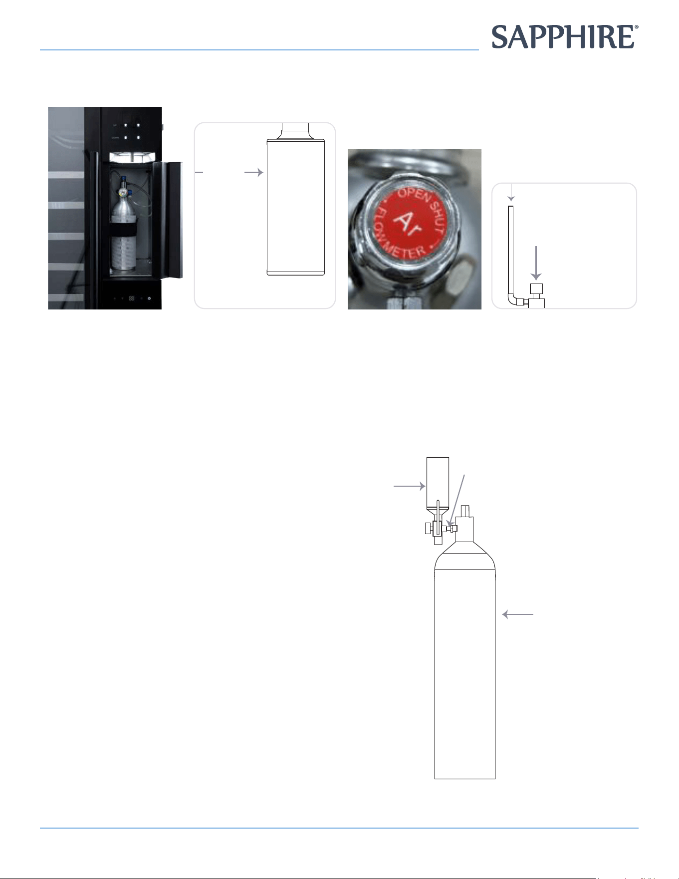
Cylinder Operation:
Note: Clockwise to close, Counter-clockwise to open. Only 1 cylinder will be connected at a time,
Main
Valve
Front View
Side View
Pressure
Valve Dial
Tubing
(connects to
wine dispenser)
Argon
Pressure
Gauge
Argon
Charging
Port
Argon
Cylinder
Main
Valve
Front View
Side View
Pressure
Valve Dial
Tubing
(connects to
wine dispenser)
Argon
Pressure
Gauge
Argon
Charging
Port
Argon
Cylinder
1. Open the door of the
Argon Bottle Chamber
2. Lightly unscrew
(Counterclockwise) the
Gas Cylinder
3. Lightly unscrew
(Counterclockwise) the
Master Dial
4. Lightly unscrew
(Counterclockwise) the
Outlet Pressure Dial
5. After the two dials are opened, and the tubes and corks are in the appropriate wine bottles, close the
door of the Argon Bottle Chamber, place a wine glass in the Wine Dispenser Platform and test the wine
dispenser buttons.
Method of lling the small Argon cylinder
1. Filling the small Argon cylinder must be
operated by a qualied professional.
2. Attach the lling connector to the outlet of
the small Argon cylinder and the large Argon
respectively, ensuring a good seal.
3. Then use a wrench to open the main switch on
the large cylinder to ll the small cylinder until
it can no longer be lled.
Small
Argon
Cylinder
Large
Argon
Cylinder
(Not Included)
Inflatable
Connection
13Instruction Manual
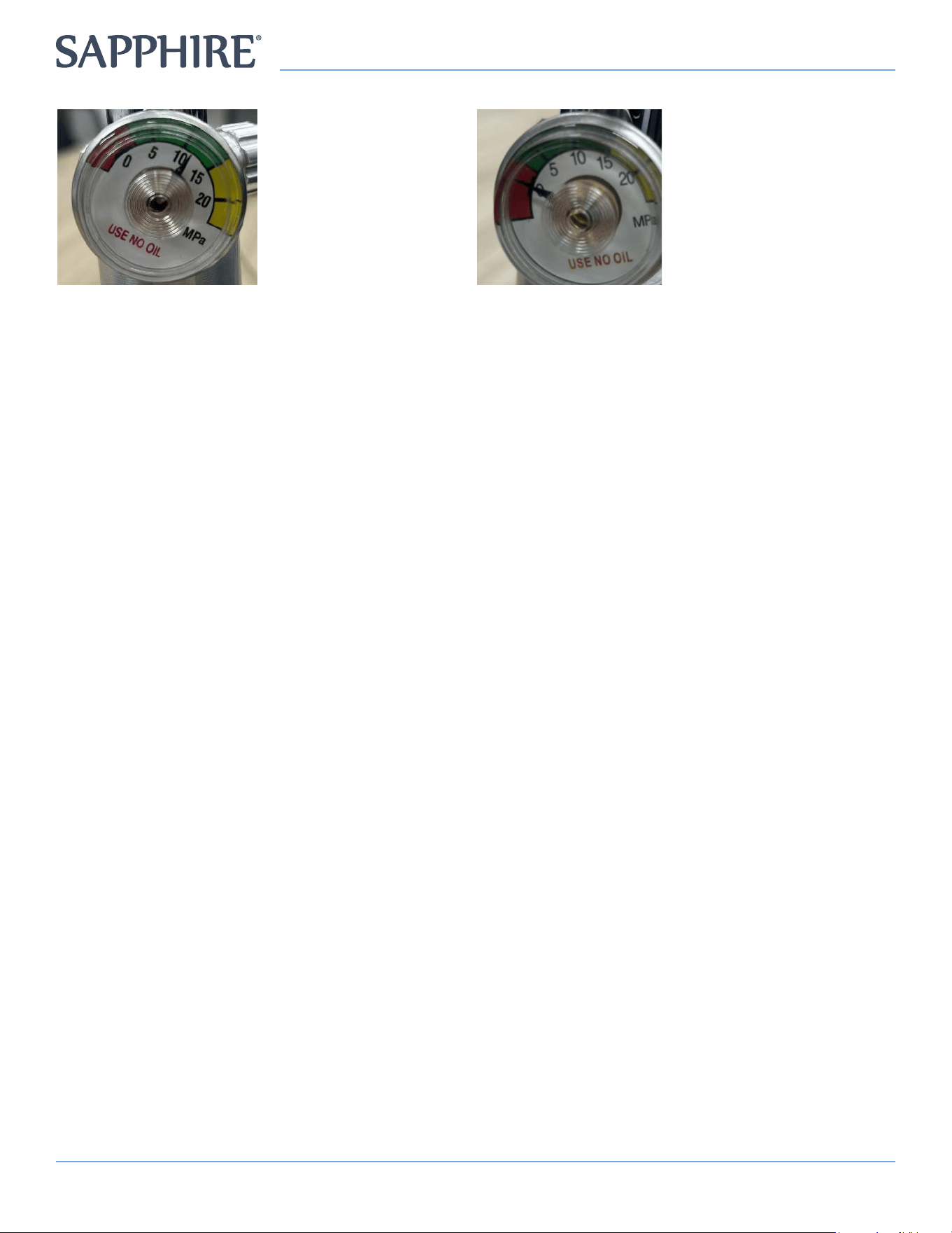
The pointer represents the state of Argon Gas in the Cylinder
Green Area: Gas pressure is Good
Red Area: Gas pressure is Low
Yellow Area: Gas pressure is too high, over-inated and needs to be deated into the Green Area.
PLACEMENT PRECAUTIONS
• When placing items in the wine cabinet, please do not block the air outlets and the air outlets on the
box, otherwise it will affect the uniformity and cooling effect of the temperature in the box;
• DO NOT place any other items inside the Argon Bottle Chamber.
CORRECT USE AND MACHINE MAINTENANCE
• Avoid opening the wine cabinet door too frequently to reduce air-conditioning leakage and cooling
efciency.
• If the door is more than 1 minute, the temperature digital management will display “E1” and the
system will alarm, please close as soon as possible.
• When placing wine in cabinet, do not block the ventilation outlet on the right side of the cabinet,
otherwise it will affect the cooling effect.
• DO NOT extend your ngers, sticks and other things into the air outlet for risk of danger and injury.
• DO NOT touch the compressor, for risk of injury and burns.
• DO NOT hang items on the door, for risk of danger and causing the unit to tip and fall.
• DO NOT block the air outlets. Keep 1 inch clearance from the front, sides and bottom of the body
where the condenser outputs hot air.
• DO NOT touch the air outlets, for risk of injury and burns
• When the cabinet is not used for an extended period of time: remove all the goods in the cabinet,
unplug the power plug, clean the cabinet, wipe and remove water and mildew, leave the door to dry.
• DO NOT damage the refrigeration loop pipe. The left and right sides of the cabinet and the box are
installed with a refrigeration line, and if these parts open or you install other objects, it may cause the
pipeline to rupture.
• When the gas cylinder is empty, remove gas cylinder, and regulator, and take to a qualied gas
supplier to ll with Argon.
• DO NOT expose gas or gas cylinders to a heat source, for risk of danger and injury.
• DO NOT damage the hose and gas path to the wine, otherwise it will affect the dispensing.
• The maximum weight capacity of each shelf is: 40 lbs (20 kg)
14 SW643TZBLK - 4-Pour Wine Bar
CLEANING
To prevent any electrical shock hazards or injury by rotating circulation fan, always disconnect the power
cord plug from the wall outlet before cleaning.
Do not splash water directly onto the cooler and do not wash with water. Short-circuit and electrical
shock could result.
Never use polishing powder, soap powder, benzine, oil or hot water as there will damage the painting
and plastic components.
Regularly clean the wine line and lter.
• Clean the inside and outside of the Wine Dispenser frequently.
• It is recommended to use only damp cloth and, if necessary, apply neutral soap-based detergents.
• If using a glass cleaner to clean the front of the unit, allow it to dry completely before restarting use.
• Turn off the unit when cleaning the inside of the unit.
• Avoid cleaning the inside of your product with scented cleaning agents.
Note:
To clean stainless steel surfaces, do not use chemicals, gasoline, alcohol, disinfectants, vinegar,
detergents aggressive, acidic or abrasive cleaning agents.
Otherwise, you may create rough spots in the material that will be susceptible to oxidation.
TAPS AND TUBES:
Proper care of the taps and wine transport tubes guarantees a long life and impeccable and
hygienic operation of your 4-Pour Wine Bar.
Cleaning the Taps
• The metal liquid outlet taps come into contact with air and this is where the wine and its sediments
undergo changes in the case of long contact time, which can lead to lines clogging.
• Additionally, during the warm seasons of the year, wine drops can attract insects. For this reason, we
recommend cleaning your taps regularly.
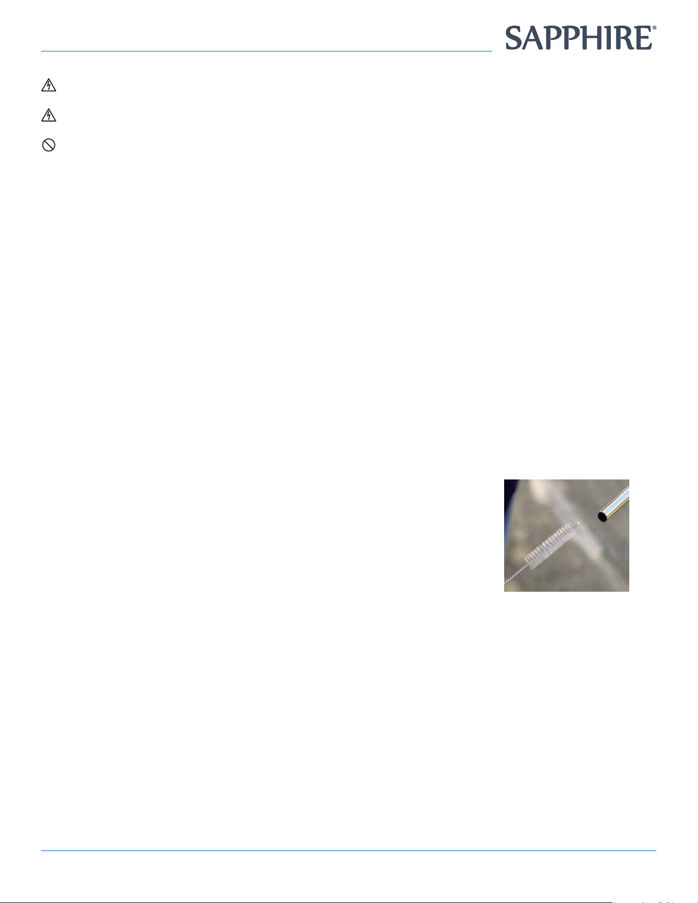
1. Use a small pipe cleaner brush (not included) and warm water.
2. Dip the pipe cleaner into warm water then insert it into the
dispenser tap.
3. Do this for all 4 taps.
Cleaning the Tubes
• The silicone tubes are responsible for transporting wine do not come into contact with air during
operation. Even so, over a long period of use they may need ushing from wine and its sediments, so
clean the tubes at regular intervals with warm water.
• We especially recommend it if you start using a new wine, or if you change a bottle of wine that was
sitting in the wine dispenser for a while.
1. Connect a bottle lled with warm drinking water to clean each circuit to be used.
2. Extract at least 700 uid oz. (200 ml) of drinking water from the bottle in each circuit and
discard this water after the cleaning.
3. During the removal of the rubber stopper, some noise is common due to the system
being pressurized.
15Instruction Manual
• If, despite following the previous care tips, deposits form in the taps and pipes, you can dissolve
them with a mixture of drinking water and a light dose of pure citric acid powder.
1. Follow the dosage instructions on the packaging .
2. If necessary, leave the citric acid act for about 20 minutes on the pipes and taps and then
rinse thoroughly with drinking water.
3. Then proceed rinsing the tubing with water.
• Regular washing with citric acid powder, at intervals of 2 or 3 months, can help prevent red wine
stains on silicone tubing. However, stains can’t be avoided completely. Please note that stained tubes
are not a hygiene risk. For reasons of visual appearance, stains can be eliminated by replacing the
tubes during maintenance.
• For residues in taps that do not want to come out, leading to deterioration of the ow, it is
recommended to call an authorized service to carry out an inspection /general maintenance on the
system. (This service is not covered under the product warranty.)
DISPOSAL
To prevent any electrical shock hazards or injury by rotating circulation fan,
always disconnect the power cord plug from the wall outlet before cleaning.
This symbol on the product, or in its packaging, indicates that this product
may not be treated as household waste. Instead, it should be taken to the
appropriate waste collection point for the recycling of electrical and electronic
equipment. For more detailed information about the recycling of this product,
please contact your local council or your household waste disposal service.
TROUBLESHOOTING
If any fault occurs, please discontinue use. Do not attempt to repair yourself. This will void the
warranty.
Fault Code Display Meaning
SERIAL NO. CODE MEANING
1 E2 Zone 1 Box (upper left temperature zone) - Temperature Sensor Fault
2 E4 Zone 2 Box (lower left temperature zone) - Temperature Sensor Fault
3 E6 Zone 3 Box (right temperature zone) - Temperature Sensor Fault
4 E9 Zone 3 (right) - Signal Line Fault Display
5 E9 Zone 1 (upper left) - Signal Line Fault Display
6 E1 Zone 1 (upper left) - Dew Point Sensor Failure
7 E3 Zone 2 (lower left) - Defrost Sensor Fault
8 E5 Zone 3 (right) - Defrost Sensor Fault
9 E9 Zone 2 (lower left) - Signal Line Fault Display
16 SW643TZBLK - 4-Pour Wine Bar
Troubles listed are for reference.
PROBLEM INSPECTION POINTS
Not working at all Check whether it is plugged-in
Is it the fuse?
Is it energized?
Not working There is a heat source or sunlight nearby
Surrounding ventilation poor
Door was not closed properly or left open for too long
Fan failure
Low Wine Flow The gas cylinder is not charged or the air pressure is not enough
The wine tube has a leak
Controlling wine PCB failure
Aging or too much pressure
Loud Noise The cabinet is placed uneven or too close to the wall
Press or fans fail
There is a loose part or fall off
When replacing parts due to machine failure, please replace with parts of the same type to reduce the risk
of re caused by incorrect parts
Note: The following phenomena is not faulty
A) The compressor does not start:
If the set temperature is below room temperature, the compressor does not start, but the heater
starts temperature compensation until it reaches the set temperature
B) Automatic startup of the compressor
When the temperature reaches the set temperature, the compressor will stop. The compressor
will be activated again after the temperature is warmed to a certain extent, to ensure that the
temperature is set in the unit.
C) Glass surface condensation
When there is a lot of humidity present in the room, the outer surface of the cabinet may develop
condensation. If the temperature setting is low, the condensation will increase accordingly, this is
too much humidity and is not a fault, just wipe it with a dry cloth.
D) Flow water:
When the cabinet is working, you may hear the sound of water owing, this is a ow of refrigerant
in the system, this is normal.
17Instruction Manual
APPENDIX
101.DVS.3.3 Qualication of workers
Every working procedure that affects safety means shall only be carried out by competent persons.
Examples for such working procedures are
a) breaking into the refrigerating circuit;
b) opening of sealed components;
c) opening of ventilated enclosures.
101.DVS.4.2 Checks to the area
Prior to beginning work on systems containing FLAMMABLE REFRIGERANTS, safety checks are necessary to
ensure that the risk of ignition is minimized. For repair to the REFRIGERATING SYSTEM.
101.DVS.4.3 Work procedure
Work shall be undertaken under a controlled procedure so as to minimize the risk of a ammable gas or
vapor being present while the work is being performed.
101.DVS.4.4 General work area
All maintenance staff and others working in the local area shall be instructed on the nature of work being
carried out. Work in conned spaces shall be avoided.
101.DVS.4.5 Checking for presence of refrigerant
The area shall be checked with an appropriate refrigerant detector prior to and during work, to ensure the
technician is aware of potentially toxic or ammable atmospheres. Ensure that the leak detection equipment
being used is suitable for use with all applicable refrigerants, i.e., non-sparking, adequately sealed, or
intrinsically safe.
101.DVS.4.6 Presence of re extinguisher
If any hot work is to be conducted on the refrigerating equipment or any associated parts, appropriate re
extinguishing equipment shall be available on hand. A dry chemical or CO2 re extinguisher should be
adjacent to the charging area.
101.DVS.4.7 No ignition sources
No person carrying out work in relation to a REFRIGERATING SYSTEM which involves exposing any pipe
work shall use any sources of ignition in such a manner that it may lead to the risk of re or explosion. All
possible ignition sources, including cigarette smoking, should be kept sufciently far away from the site
of installation, repairing, removing and disposal, during which refrigerant can possibly be released to the
surrounding space. Prior to work taking place, the area around the equipment shall be surveyed to make
sure that there are no ammable hazards or ignition risks. “No Smoking” signs shall be displayed.
101.DVS.4.8 Ventilated area
Ensure that the area is in the open or that it is adequately ventilated before breaking into the system or
conducting any hot work. A degree of ventilation shall continue during the period that the work is carried
out. The ventilation should safely disperse any released refrigerant and preferably expel it externally into the
atmosphere.
101.DVS.4.9 Checks to the refrigerating equipment
Where electrical components are being changed, they shall be t for the purpose and to the correct
specication. At all times, the manufacturer’s maintenance and service guidelines shall be followed. If in
doubt, consult the manufacturer’s technical department for assistance.
The following checks shall be applied to installations using FLAMMABLE REFRIGERANTS:
a) The actual REFRIGERANT CHARGE is in accordance with the room size within which the refrigerant
containing parts are installed;
b) The ventilation machinery and outlets are operating adequately and are not obstructed;
c) if an indirect refrigerating circuit is being used, the secondary circuit shall be checked for the presence
of refrigerant;
d) marking to the equipment continues to be visible and legible. Markings and signs that are illegible shall
be corrected;
18 SW643TZBLK - 4-Pour Wine Bar
e) refrigerating pipe or components are installed in a position where they are unlikely to be exposed
to any substance which may corrode refrigerant containing components, unless the components are
constructed of materials which are inherently resistant to being corroded or are suitably protected against
being so corroded.
101.DVS.4.10 Checks to electrical devices
Repair and maintenance to electrical components shall include initial safety checks and component
inspection procedures. If a fault exists that could compromise safety, then no electrical supply shall be
connected to the circuit until it is satisfactorily dealt with. If the fault cannot be corrected immediately but it
is necessary to continue operation, an adequate temporary solution shall be used. This shall be reported to
the owner of the equipment, so all parties are advised.
Initial safety checks shall include:
a) that capacitors are discharged: this shall be done in a safe manner to avoid possibility of sparking;
b) that no live electrical components and wiring are exposed while charging, recovering or purging
the system;
c) that there is continuity of earth bonding.
101.DVS.5 Repairs to sealed components
101.DVS.5.1 During repairs to sealed components, all electrical supplies shall be disconnected from
the equipment being worked upon prior to any removal of sealed covers, etc. If it is absolutely necessary
to have an electrical supply to equipment during servicing, then a permanently operating form of leak
detection shall be located at the most critical point to warn of a potentially hazardous situation.
101.DVS.5.2 Particular attention shall be paid to the following to ensure that by working on electrical
components, the casing is not altered in such a way that the level of protection is affected. This shall
include damage to cables, excessive number of connections, terminals not made to original specication,
damage to seals, incorrect tting of glands, etc. Ensure that the apparatus is mounted securely. Ensure
that seals or sealing materials have not degraded to the point that they no longer serve the purpose of
preventing the ingress of ammable atmospheres. Replacement parts shall be in accordance with the
manufacturer’s specications.
101.DVS.6 Repair to intrinsically safe components
Do not apply any permanent inductive or capacitance loads to the circuit without ensuring that this
will not exceed the permissible voltage and current permitted for the equipment in use. Intrinsically
safe components are the only types that can be worked on while live in the presence of a ammable
atmosphere. The test apparatus shall be at the correct rating. Replace components only with parts specied
by the manufacturer. Other parts can result in the ignition of refrigerant in the atmosphere from a leak.
NOTE The use of silicon sealant can inhibit the effectiveness of some types of leak detection
equipment. Intrinsically safe components do not have to be isolated prior to working on them.
101.DVS.7 Cabling
Check that cabling will not be subject to wear, corrosion, excessive pressure, vibration, sharp edges, or any
other adverse environmental effects. The check shall also take into account the effects of aging or continual
vibration from sources such as compressors or fans.
101.DVS.8 Detection of ammable refrigerants
Under no circumstances shall potential sources of ignition be used in the searching for or detection of
refrigerant leaks. A halide torch (or any other detector using a naked ame) shall not be used. The following
leak detection methods are deemed acceptable for all refrigerant systems. Electronic leak detectors may be
used to detect refrigerant leaks but, in the case of FLAMMABLE REFRIGERANTS, the sensitivity might not be
adequate, or might need recalibration. (Detection equipment shall be calibrated in a refrigerant-free area.)
Ensure that the detector is not a potential source of ignition and is suitable for the refrigerant used. Leak
detection equipment shall be set at a percentage of the LFL of the refrigerant and shall be calibrated to the
refrigerant employed, and the appropriate percentage of gas (25 % maximum) is conrmed. Leak detection
uids are also suitable for use with most refrigerants but the use of detergents containing chlorine shall be
avoided as the chlorine can react with the refrigerant and corrode the copper pipe-work.
19Instruction Manual
NOTE Examples of leak detection uids are
– bubble method,
– uorescent method agents.
• If a leak is suspected, all naked ames shall be removed/extinguished.
• If a leakage of refrigerant is found which requires brazing, all of the refrigerant shall be recovered
from the system, or isolated (by means of shut off valves) in a part of the system remote from the
leak. Removal of refrigerant shall be according to Clause 101.DVS.9.
101.DVS.9 Removal and evacuation
When breaking into the refrigerant circuit to make repairs – or for any other purpose – conventional
procedures shall be used. However, for ammable refrigerants it is important that best practice be followed,
since ammability is a consideration. The following procedure shall be adhered to:
a) safely remove refrigerant following local and national regulations;
b) purge the circuit with inert gas;
c) evacuate (optional for A2L);
d) purge with inert gas (optional for A2L);
e) open the circuit by cutting or brazing.
The refrigerant charge shall be recovered into the correct recovery cylinders if venting is not allowed by
local and national codes. For appliances containing ammable refrigerants, the system shall be purged with
oxygen-free nitrogen to render the appliance safe for ammable refrigerants. This process might need to
be repeated several times. Compressed air or oxygen shall not be used for purging refrigerant systems.
For appliances containing ammable refrigerants, refrigerants purging shall be achieved by breaking the
vacuum in the system with oxygen-free nitrogen and continuing to ll until the working pressure is achieved,
then venting to atmosphere, and nally pulling down to a vacuum (optional for A2L). This process shall be
repeated until no refrigerant is within the system (optional for A2L). When the nal oxygen-free nitrogen
charge is used, the system shall be vented down to atmospheric pressure to enable work to take place.
Ensure that the outlet for the vacuum pump is not close to any potential ignition sources and that ventilation
is available.
101.DVS.10 Charging procedures
In addition to conventional charging procedures, the following requirements shall be followed. a) Ensure
that contamination of different refrigerants does not occur when using charging equipment. Hoses or lines
shall be as short as possible to minimize the amount of refrigerant contained in them.
b) Cylinders shall be kept in an appropriate position according to the instructions.
c) Ensure that the REFRIGERATING SYSTEM is earthed prior to charging the system with refrigerant.
d) Label the system when charging is complete (if not already).
e) Extreme care shall be taken not to overll the REFRIGERATING SYSTEM.
Prior to recharging the system, it shall be pressure-tested with the appropriate purging gas. The system shall
be leak-tested on completion of charging but prior to commissioning. A follow up leak test shall be carried
out prior to leaving the site.
101.DVS.11 Decommissioning
Before carrying out this procedure, it is essential that the technician is completely familiar with the
equipment and all its detail. It is recommended good practice that all refrigerants are recovered safely.
Prior to the task being carried out, an oil and refrigerant sample shall be taken in case analysis is required
prior to re-use of recovered refrigerant. It is essential that electrical power is available before the task is
commenced.
a) Become familiar with the equipment and its operation.
b) Isolate the system electrically.
c) Before attempting the procedure, ensure that:
i) mechanical handling equipment is available, if required, for handling refrigerant cylinders;
ii) all personal protective equipment is available and being used correctly;
iii) the recovery process is supervised at all times by a competent person;
iv) recovery equipment and cylinders conform to the appropriate standards.
20 SW643TZBLK - 4-Pour Wine Bar
d) Pump down refrigerant system, if possible.
e) If a vacuum is not possible, make a manifold so that refrigerant can be removed from various parts of
the system.
f) Make sure that cylinder is situated on the scales before recovery takes place.
g) Start the recovery machine and operate in accordance with instructions.
h) Do not overll cylinders (no more than 80 % volume liquid charge).
i) Do not exceed the maximum working pressure of the cylinder, even temporarily.
j) When the cylinders have been lled correctly and the process completed, make sure that the cylinders
and the equipment are removed from site promptly and all isolation valves on the equipment are
closed off.
k) Recovered refrigerant shall not be charged into another REFRIGERATING SYSTEM unless it has been
cleaned and checked.
101.DVS.12 Labeling
Equipment shall be labeled stating that it has been decommissioned and emptied of refrigerant. The label
shall be dated and signed. For appliances containing FLAMMABLE REFRIGERANTS, ensure that there are
labels on the equipment stating the equipment contains FLAMMABLE REFRIGERANT.
101.DVS.13 Recovery
When removing refrigerant from a system, either for servicing or decommissioning, it is recommended
good practice that all refrigerants are removed safely.
When transferring refrigerant into cylinders, ensure that only appropriate refrigerant recovery cylinders
are employed. Ensure that the correct number of cylinders for holding the total system charge is available.
All cylinders to be used are designated for the recovered refrigerant and labeled for that refrigerant (i.e.,
special cylinders for the recovery of refrigerant). Cylinders shall be complete with pressure-relief valve and
associated shut-off valves in good working order. Empty recovery cylinders are evacuated and, if possible,
cooled before recovery occurs.
The recovery equipment shall be in good working order with a set of instructions concerning the
equipment that is at hand and shall be suitable for the recovery of all appropriate refrigerants including,
when applicable, FLAMMABLE REFRIGERANTS. In addition, a set of calibrated weighing scales shall be
available and in good working order. Hoses shall be complete with leak-free disconnect couplings and in
good condition. Before using the recovery machine, check that it is in satisfactory working order, has been
properly maintained and that any associated electrical components are sealed to prevent ignition in the
event of a refrigerant release. Consult manufacturer if in doubt. The recovered refrigerant shall be returned
to the refrigerant supplier in the correct recovery cylinder, and the relevant waste transfer note arranged. Do
not mix refrigerants in recovery units and especially not in cylinders.
If compressors or compressor oils are to be removed, ensure that they have been evacuated to an
acceptable level to make certain that FLAMMABLE REFRIGERANT does not remain within the lubricant. The
evacuation process shall be carried out prior to returning the compressor to the suppliers. Only electric
heating to the compressor body shall be employed to accelerate this process. When oil is drained from a
system, it shall be carried out safely.
WARNING
A3
• Do not use means to accelerate the defrosting process or to clean,
other than those recommended by the manufacturer.
• The appliance shall be stored in a room without continuously
operating ignition sources (for example: open ames, an operating
gas appliance or an operating electric heater.)
• Do not pierce or burn.
• Be aware that refrigerants may not contain an odor.
21Instruction Manual
LIMITED WARRANTY COVERAGE
The Legacy Companies, warrants to the original purchaser of its SAPPHIRE products that they will be free from defects in materials
and workmanship for the following time periods from the date of purchase shown on the sales receipt:
• Two (2) year Parts & On-site Labor
• Five (5) years Compressor Warranty (Parts only)
WARRANTY EXCLUSIONSWARRANTY EXCLUSIONS
NO CONSEQUENTIAL DAMAGES:
SAPPHIRE and The Legacy Companies are not responsible for any economic loss or special, indirect or consequential damages
including without limitation; loss of revenue and loss or damage arising from food or product spoilage claims.
WARRANTY IS NOT TRANSFERABLE:
This warranty is not transferable or assignable and applies only to the original veried purchaser.
NO IMPLIED WARRANTY OF MERCHANTABILITY OR FITNESS FOR PARTICULAR SERVICE:
There are no other warranties statutory, express, or implied. This Limited Warranty is the exclusive warranty and made in lieu of all
other warranties including any implied warranties or any warranties of merchantability or tness for a particular purpose.
FILING WARRANTY CLAIMS:
All warranty claims for SAPPHIRE products must be made directly through The Legacy Company’s Technical Service Department.
All claims should include: model and serial number, proof of purchase, date of installation, location purchased, and all pertinent
information supporting the existence of the claim.
IMPROPER ELECTRICAL AND WATER CONNECTIONS:
SAPPHIRE and The Legacy Companies are not responsible for the repair or replacement of any failed or damaged components
resulting from electrical power failure, the use of extension cords, low voltage or voltage spikes to the unit. Likewise, repair or
replacement attributable to low water pressure, high water pressure or contaminated water are not covered by this Limited
Warranty.
IMPROPER USAGE:
Neither SAPPHIRE nor The Legacy Companies assumes liability for parts or labor coverage for component failure or other damages
resulting from improper usage or installation or failure to clean and/or maintain the product as set forth in the Owner’s Manual
provided with each unit.
CONSUMABLES:
This warranty does not include consumable parts such as water lters and light bulbs.
ADJUSTMENTS & CALIBRATIONS:
Adjustments including calibrations, leveling, tightening of fasteners, or utility connections normally associated with the original
installation are the responsibility of the dealer, installer or the end user and not the responsibility of SAPPHIRE or The Legacy
Companies and will not be considered warranty issues for this Limited Warranty.
CONSEQUENTIAL DAMAGES:
This warranty does not cover any defect due to, or resulting from, ordinary wear and tear, handling, abuse, misuse, or harsh chemical
action, nor shall it extend to any product from which the serial number has been removed or altered, or modications made by
unauthorized service personnel or damage by ood, re, earthquake or other Acts of God.
OUTSIDE U.S. & CANADA:
This warranty does not apply to, and SAPPHIRE and The Legacy Companies are not responsible for any warranty claims made on
products sold or used outside of the United States and Canada or any territories of the United States of America.
ALL REPAIRS AND SERVICE MUST BE MADE BY A SAPPHIRE AUTHORIZED TECHNICIAN.
Customer Service: 1.866.754.6672 | [email protected]
3355 Enterprise Ave #160, Ft. Lauderdale, FL 33331 | 954.202.7419 | sapphireappliances.com
03.11.25
22