Part No. 15333 Rev. Cwww.insinkerator.com/foodservice
Please be certain that the person who installs or uses this appliance carefully reads
and understands the Safety Instructions contained in this manual.
NOTICE is used to address practices not related to physical injury.
CAUTION indicates a hazardous situation which, if not avoided, could result in
minor or moderate injury.
WARNING indicates a hazardous situation which, if not avoided, could result in
death or serious injury.


3
Introduction/Typical Installation
Introduction ..................................................................................... 4
Typical Installation ........................................................................... 4
Waste Xpress Features ................................................................................. 5
WX-101A Control Features/Mounting Control Center
Introduction ..................................................................................... 6
Typical Installation ........................................................................... 6
Installing Disposer ........................................................................................ 7
InSinkErator Mounting Assemblies
Standard Mounting.......................................................................... 8
Special Mounting ............................................................................ 8
Installing Waste Xpress
Waste Xpress Diagrams .................................................................. 9
Installing Waste Xpress ................................................................. 10
Electrical Connections................................................................... 10
Plumbing Connections
Waste Inlet Line ............................................................................. 11
Reverse Auger Screen ................................................................... 11
Change Waste Inlet ....................................................................... 11
Waste Outlet Line .......................................................................... 12
Plumbing Connections .................................................................. 12
Water Supply Connection ............................................................. 12
Routing Water Flow ....................................................................... 12
Electrical Connections ............................................................................... 13
Operating Instructions
Pre-Operating ................................................................................ 14
Operating Instruction ..................................................................... 15
Operating Waste Xpress System .................................................. 16
Operational Tips ............................................................................ 16
Cleaning Instruction ................................................................................... 17
Troubleshooting
System Troubleshooting ................................................................ 18
Disposer Troubleshooting ............................................................. 21
Waste Xpress Troubleshooting ...................................................... 22
Wiring Diagrams
Model No. WX-101A-5 (208/240V, 3 phase) ................................... 24
Model No. WX-101A-6 (380/460V, 3 phase) ................................... 26
Warranty ....................................................................................................... 28
Table of Contents
Introduction/Typical Installation
4
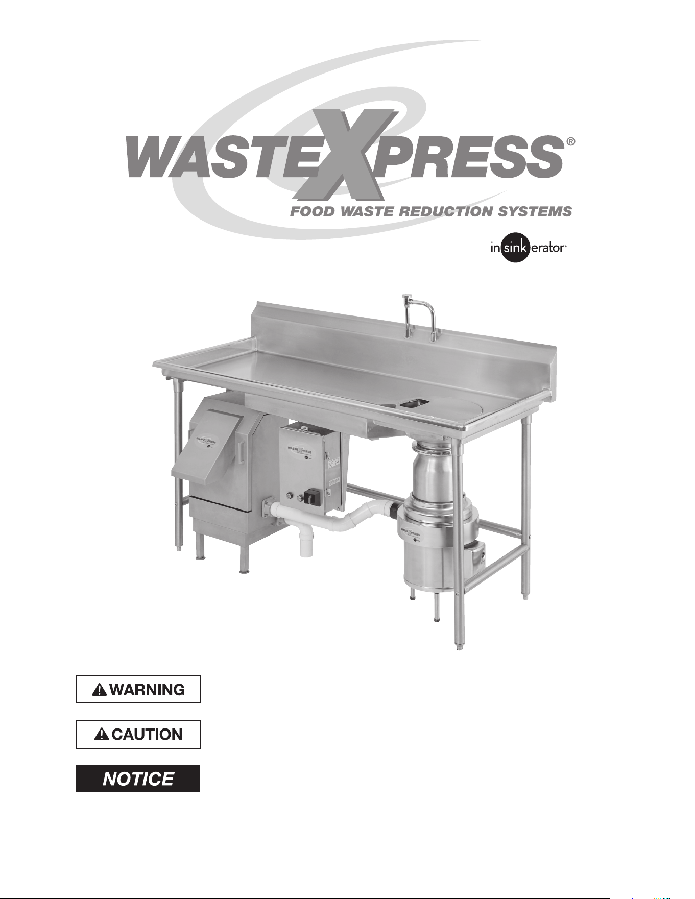
INTRODUCTION
The InSinkErator
®
Waste Xpress
®
is a
Foodservice kitchen waste reduction
system that utilizes a standard Foodservice
disposer in line with the Waste Xpress
dewatering system. The kitchen waste
is ground through the disposer then
transferred to the Waste Xpress where
it is compressed. After the waste is
compressed, the liquids are sent down the
drain line and the solid waste exiting the
Waste Xpress is up to 85% less in volume
(see Figure 1 for typical installation).
Important – These installation
instructions are for the benet of the
installing contractor. InSinkErator and/or
InSinkErator Factory Authorized Service
Centers do not make original installations.
For technical information not covered in
these instructions, contact the supplier,
an InSinkErator Field Sales Representative,
or InSinkErator Foodservice Sales and
Service at 1-800-845-8345.
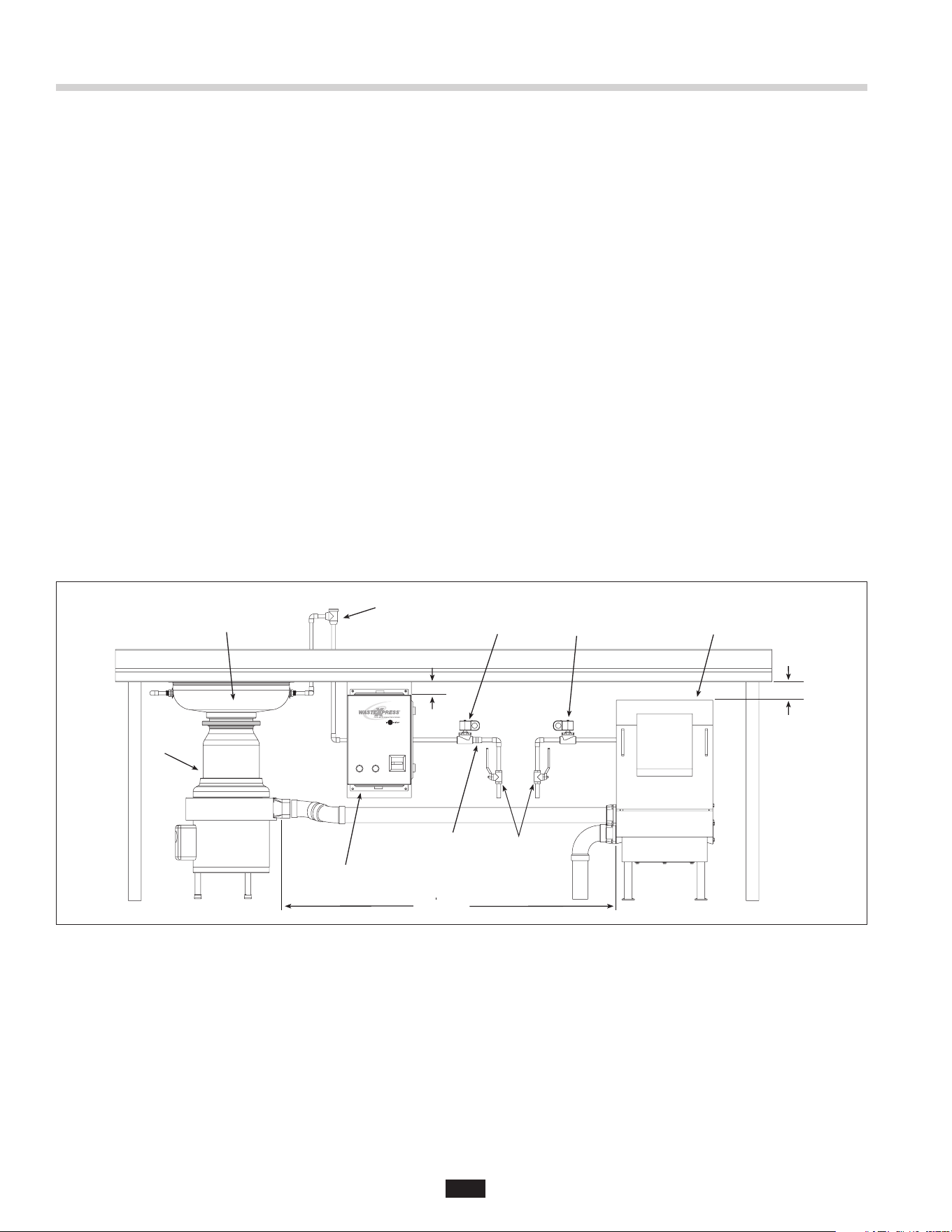
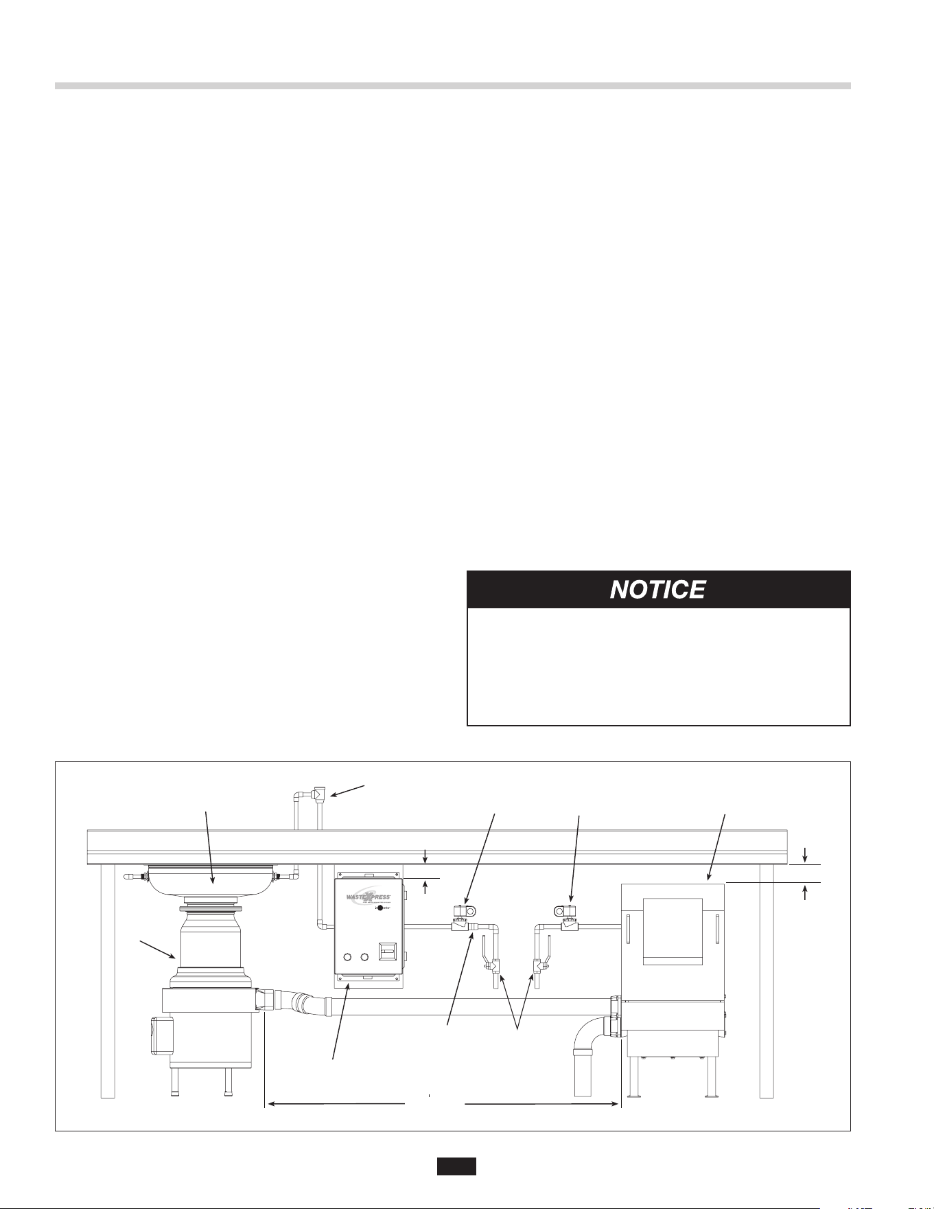
TYPICAL INSTALLATION
A typical Waste Xpress installation
incorporates the following
connections (see Figure 1):
• Waste Xpress
• Disposer
• Control Center
• Syphon breaker
• Solenoid valves (2)
• Water shut off valve
• Bowl or trough
• Flow control valve
• Cold water (sink or trough)
• Hot water (Waste Xpress)
REQUIRED TOOLS /
MATERIALS
The following items are needed to
install the disposer:
• Screwdriver
• Adjustable wrench
• Pipe wrench
• Wire nuts
• 7/16" nut driver
The following items may be
needed to install the disposer:
• Plumbing putty
• Hacksaw
• Drain auger
Figure 1. Typical Installation
Flow Control Valve
Disposer
Sink Bowl
Syphon Breaker
Cold Water SolenoidHot Water SolenoidWaste Xpress
Shut Off Valve
(supplied
by others)
WX-101A Controller
10 max
(3.1 m max)
1-1/2" min
(38.1 mm
min)
1" min
(25.4 mm min)
5
FEATURES
COMPACT SIZE
The Waste Xpress
®
is designed to t under a 34" high
commercial kitchen table.
WASTE REDUCTION
Reduces volume by up to 85%.
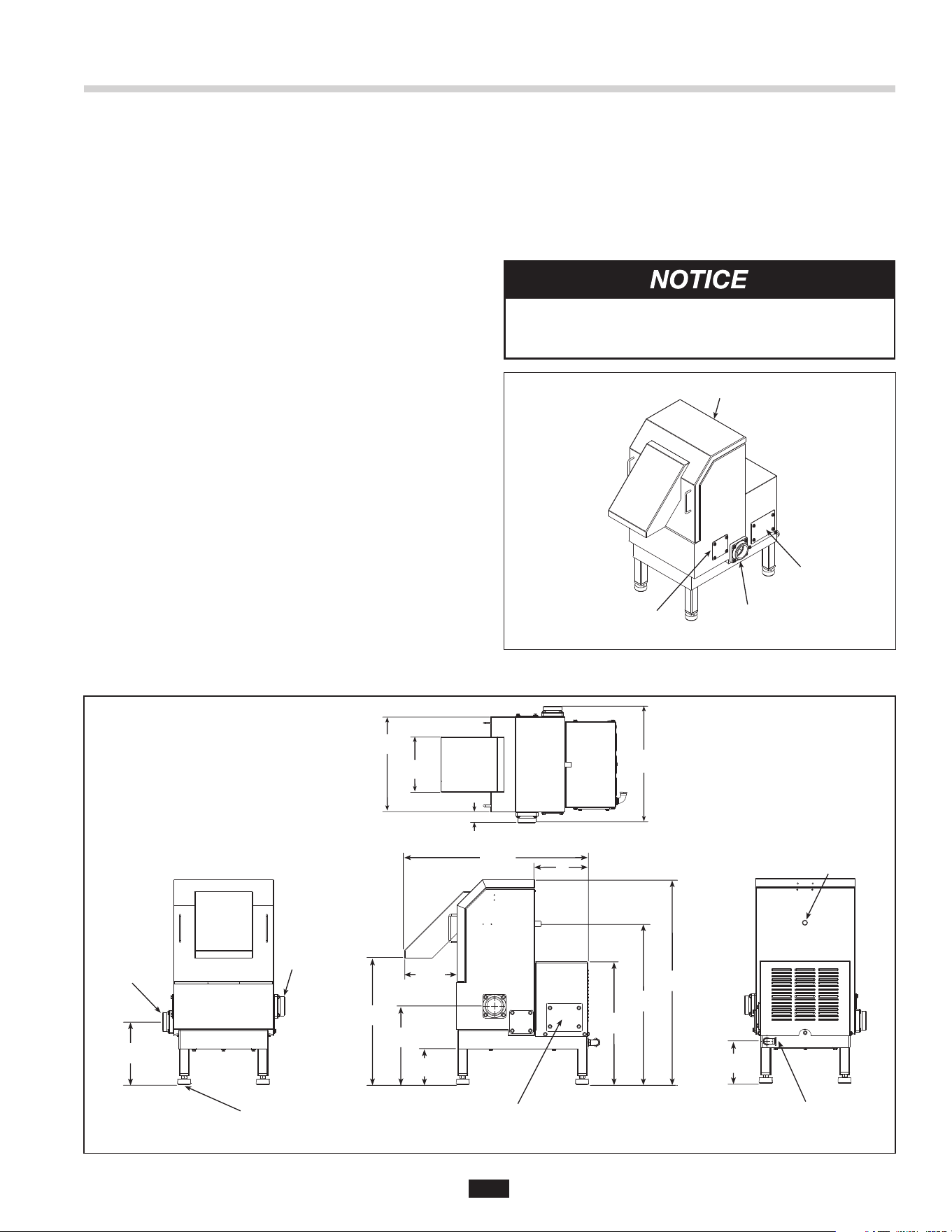
SAFETY INTERLOCK
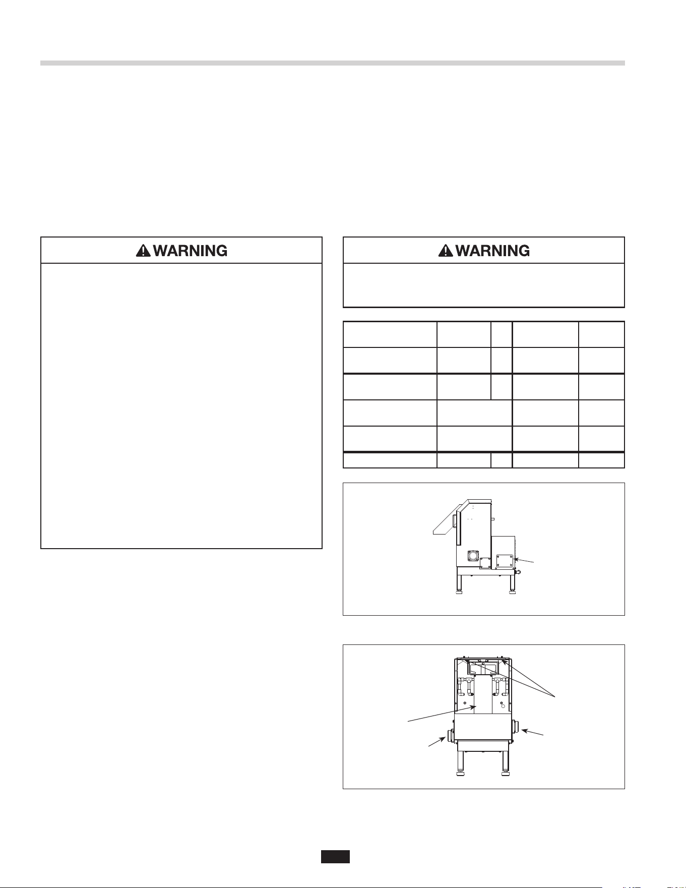
The Waste Xpress is equipped with safety interlock
on the discharge chute (see Figure 2). This interlock
prevents the system (disposer & Waste Xpress) from
operating unless the discharge chute is properly seated.
DRAIN CONNECTIONS
• Water outlet should be routed directly to a oor drain
(and as close to the Waste Xpress as possible).
• The 2" NPT waste inlet connection can be mounted
on either side.
• The 2" NPT water outlet connection can be mounted
on either side.
• For trough or high water ow applications, connect
both Water Outlet connections for optimum
cabinet drainage.
• All drain lines must be a minimum 2" NPT in diameter.
PROPERTY DAMAGE
Plastic wrap, cans, silverware, rubber, glass and
crockery cannot be processed.
Safety Interlock
Water Outlet
(either side)
Waste Inlet
Terminal
Connection
Figure 2.
21-3/4"
(552.5 mm)
21-1/8"
(536.6 mm)
26-7/8"
(682.6 mm)
33-1/2"
(850.9 mm)
8"
(203.2 mm)
27-3/ 8"
(695.3 mm)
7-7/8"
(200.0 mm)
Electrical Connection Cover
14-1/2"
(368.3 mm)
8-1/8"
(206.4 mm)
15"
(381 mm)
18-3/4"
(476.3 mm)
1-5/8"
(41.3 mm)
9-1/8"
(231.8 mm)
1/2"
(12.7 mm)
Electrical Inlet
1/2"
(12.7 mm)
Hot Water Inlet
12-1/8"
(308.0 mm)
2"
(50.8 mm)
NPT Outlet
(Either Side)
2"
(50.8 mm)
NPT Inlet
(Either Side)
Leveling Foot
Adjustment Range
2-3/4"
(69.9 mm)
8-5/8"
( 219.1 mm )
Figure 3. Waste Xpress Dimensions
CONSTRUCTION
Stainless steel construction (for physical size see
Figure 3).
WASTE MIX
The Waste Xpress can process non-food waste such
as paper, light and rigid plastic or food wrappings when
mixed with a minimum of 50% food waste.
Waste Xpress Features
Waste Inlet
(either side)
Waste Outlet
(either side)
Terminal
Connection
Safety Interlock
6
The WX-101A Control Center is CUL
®
US listed for use
with InSinkErator Waste Xpress
®
food waste reduction
systems. The control center operates the disposer and
Waste Xpress. Its main functions are:
• To start and stop the disposer/Waste Xpress system.
• To reverse the direction of the disposer motor
automatically upon restart.
• To start the water ow to the disposer.
• To allow water ow for several minutes to ush the
drain line after the disposer is turned off.
Model Part No. Voltage Phase
WX-101A-5 15258 208/240V 3
WX-101A-6 15258A 380/460V 3
FEATURES
SINGLE BUTTON OPERATION
Disposer and Waste Xpress are controlled by simple
ON/OFF button operation.
AUTOMATIC REVERSE
The disposer motor will reverse its direction of
rotation automatically upon restart. To avoid motor
damage, a delay feature prevents reversing until
the post ush is complete.
WATER SHUTOFF DELAY (POST FLUSH)
After the motor is turned off, the water continues to
ow for up to 10 minutes. The length of this post ush
is controlled by the water shutoff delay timer. The post
ush helps ensure that ground food waste is ushed
out of the drain line.
AUTOMATIC TIMED DISPOSER SHUTOFF
This water saving feature allows the system to run for
10 minutes before it automatically shuts off and must
be manually restarted.
LINE DISCONNECT SWITCH
The switch on the front panel of the control center
disconnects the line voltage. It interlocks with the front
cover so that the cover cannot be opened unless the
switch is in the off position.
LOW VOLTAGE CONTROL
Control operates on a 24 V solid state control circuit.
ENCLOSURE
Stainless steel NEMA 4 construction.
WX TIMER HOT WATER SPRAY ADJUSTABLE
Factory set for 2 minutes off 10 second on controls hot
water spray for cleaning of screen.
Table 1. Electrical Specifications
WX-101A Control Features/Mounting Control Center
15-1/8"
(384.2 mm)
14"
(355.6 mm)
15-3/4"
(400.1 mm)
9-7/8"
(250.8 mm)
8-1/4"
(209.6 mm)
5-1/4"
(133.4 mm)
5-5/16"
(134.9 mm)
6-3/4"
(171.5 mm)
1"
(25.4 mm)
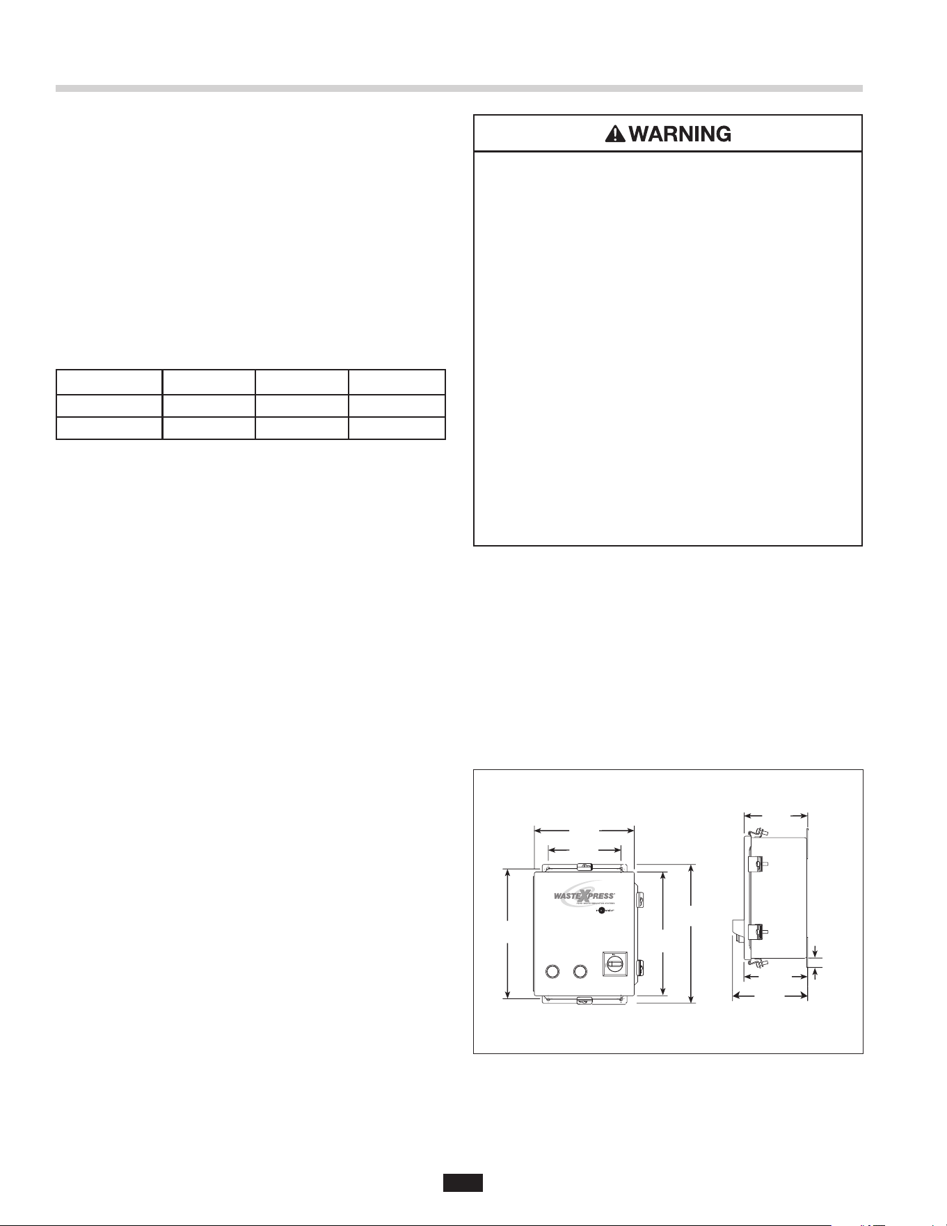
MOUNTING THE CONTROL CENTER
Use the anges at the back of the control center
enclosure and only mount panel in the upright vertical
position (door hinge is on the left). See Figure 4.
Locate control center within sight of disposer per
local codes.
If box is mounted to the sink table, recess the box so
that the buttons do not extend beyond the table’s edge
(see Figure 4).
Figure 4. Control Center Dimensions
ELECTRICAL SHOCK
• Ensure that Waste Xpress voltage and phase
match that of the electrical supply, control center
& disposer. Check nameplate for specication.
• Electrical connections should be made by a
qualied electrician and should comply with all
local codes.
• Turn off electrical supply to Waste Xpress,
control center & disposer before attempting to
work on it. Test with a volt meter or circuit tester
to ensure that power is off.
• Do not operate unit with panels removed.
• All components (disposer, WX, control center
and solenoids) must be carefully and permanently
grounded.
• A properly fused disconnect must be installed at
Waste Xpress, control center & disposer electrical
supply source.
• Use only NEMA 4 watertight electrical connectors
when connecting to junction box.
7
PERSONAL INJURY
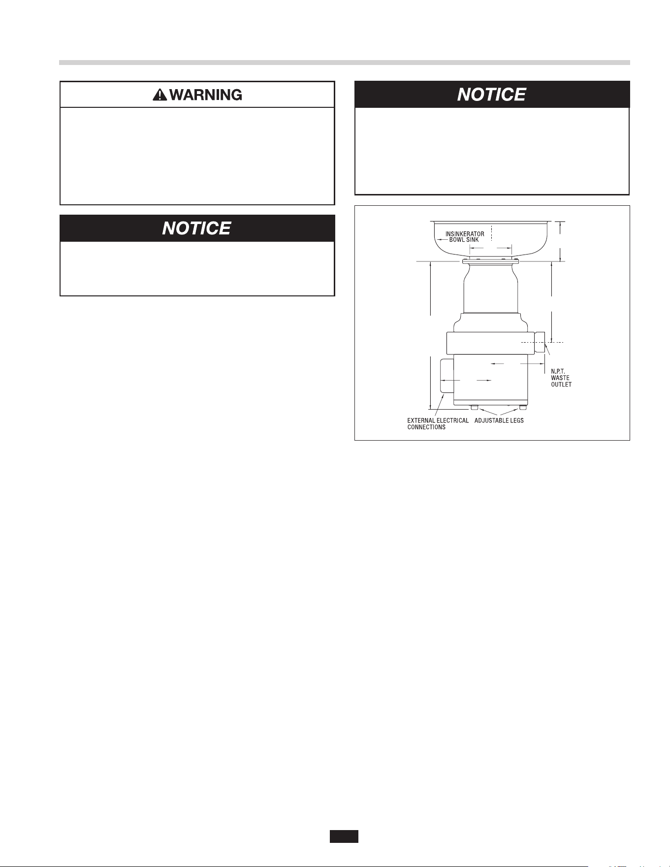
• For safe operation, the minimum required distance
from the table top or trough to the mounting ange
is 6 inches for standard body disposers
(as specied by UL). See Figure 5.
• Moving shredder parts may cause serious injury if
a hopper or cone is not properly installed.
DISPOSER MOUNTING
The disposer can be mounted to the sink or trough
using a standard InSinkErator mount or an
InSinkErator mounting adaptor.
NOTE: The InSinkErator #5 Sink Flange can not be
used with the Waste Xpress system.
NOTE: InSinkErator must approve attachment to a
non-InSinkErator sink.
CLEAN THE DRAIN LINE
With a drain line auger, periodically clear away all
hardened waste material in the horizontal drainpipe
running from the drain trap to the main waste line.
PROPERTY DAMAGE
To avoid excess vibration, InSinkErator
recommends a minimum countertop thickness
of 16 gage stainless steel.
Figure 5.
Installing Disposer
23-3/4"
TO
31-1/8"
(603.25 mm
TO
790.58 mm)
6-1/2"
(165.10 mm)
8-3/4"
(222.25 mm)
8-3/4"
(222.25 mm)
13"
(330.20 mm)
3"
(76.20 mm)
6-5/8"
(168.28 mm)
PROPERTY DAMAGE
Clean the drain line prior to connecting the disposer.
With a drain line auger, ensure that all preexisting
hardened waste material in the horizontal drainpipe
running from the drain trap to the main waste line is
cleared.
8
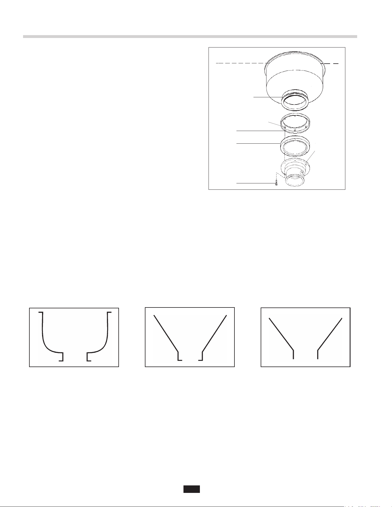
STANDARD MOUNTING ASSEMBLY
1. Place mounting ange (1) over the existing collar
adaptor connection lip or sink bowl ange (this may
require some force).
2. Push the mounting ange up out of the way and t
the groove in the mounting gasket (2) onto the
connection lip. Make sure the gasket is fully seated
on the ange.
3. Push the mounting ange down over the mounting
gasket, tting the threaded mounting ange fasteners
into the recesses in the top of the mounting gasket.
4. From the bottom, insert two screws through opposite
sides of the at gasket (3) and mounting ange, into
the threaded fasteners in the existing ange.
The screws should protrude about 1/4" below the
mounting gasket.
5. Position the disposer beneath the mounting gasket
and raise it to engage the two protruding screws in
the disposer body ange keyhole slots. Secure the
remaining screws and position the disposer correctly
for the plumbing connections. If disposer legs are
included, adjust the legs to support the disposer.
SPECIAL INSINKERATOR MOUNTING ASSEMBLIES
When installing an InSinkErator Foodservice disposer to any other mounting conguration, a special mounting
adaptor kit is required. The special mountings are described in the Mounting Adaptor Selection Guide (for more
information, call 1-800-845-8345 or go to www.insinkerator.com). Figures 8-10 show examples of non-InSinkErator
style sinks. (Mounting instructions are included in each special mounting adaptor kit.)
Figure 7: Inward Flange
Figure 8: Straight FlangeFigure 6: Outward Flange
#6 Collar Adaptor
(1) Mounting Flange
(2) Mounting Gasket
(3) Flat Gasket
Disposer Body Flange
1/4” Screw
#7 Collar Adaptor
(1) Mounting Flange
(2) Mounting Gasket
1/4” Screw
Disposer Body Flange
Figure 8. Outward Flange
Figure 9. Inward Flange Figure 10. Straight Flange
InSinkErator Mounting Assemblies
Figure 6. Adaptor Assembly with Disposer.
Sink Bowl
Connection Lip
Threaded Fasteners
1
2
Keyhole
Disposer Body Flange Slots (2)
3
SINK
9
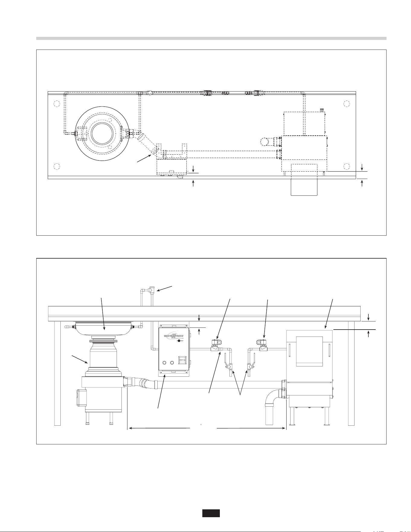
Figure 12. Typical Installation Diagram
45˚ bend shown
(max of 4 can be used)
3"
(76.2 mm)
1-1/2"
( 38 .1 m m)
Installing the Waste Xpress
Flow Control Valve
Disposer
Sink Bowl
Syphon Breaker
Cold Water SolenoidHot Water SolenoidWaste Xpress
Shut Off Valve
(supplied
by others)
WX-101A Controller
10 max
(3.1 m max)
1-1/2" min
(38.1 mm
min)
1" min
(25.4 mm min)
Figure 11. Top View
10
ELECTRICAL SHOCK
• Ensure that Waste Xpress voltage and phase
match that of the electrical supply, control center
& disposer. Check nameplate for specication.
• Electrical connections should be made by a
qualied electrician and should comply with all
local codes.
• Turn off electrical supply to Waste Xpress,
control center & disposer before attempting to
work on it. Test with a volt meter or circuit tester
to ensure that power is off.
• Do not operate unit with panels removed.
• All components (disposer, WX, control center
and solenoids) must be carefully and permanently
grounded.
• A properly fused disconnect must be installed at
Waste Xpress, control center & disposer electrical
supply source.
• Use only NEMA 4 watertight electrical connectors
when connecting to junction box.
WASTE XPRESS LOCATION
NOTE: Prior to installing the Waste Xpress the
disposer and control center should be installed as
specified within this manual.
• Position Waste Xpress within 10 feet of the disposer
outlet ange. A maximum of four (4) 90º elbows can
be used between the disposer and Waste Xpress
(prefer 45º elbow).
• Level Waste Xpress by turning the legs in or out
with a wrench. Place a level on top of the unit.
ELECTRICAL CONNECTIONS
The Waste Xpress system requires power only to the
control center. The control center powers the disposer
and Waste Xpress.
1. Remove retaining screw and disposer
electrical cover.
2. Open control center cover by loosening locking
clamps securing it.
3. Remove terminal cover from Waste Xpress
(see Figure 13).
4. Connect incoming power line to electrical door
disconnect switch in WX-101A.
5. Connect disposer motor leads to terminal
block locations.
6. Connect cold water solenoid to appropriate
terminals 4 and 13. Connect hot water solenoid to
terminal 18 and 7.
7. Connect wire bundle between WX-101A and
Waste Xpress unit as detailed in wiring diagram.
Door interlock connections are #3 and #95. Replace
terminal cover.
8. Wire per local electrical codes and install
using NEMA 4 watertight electrical connectors
(not supplied).
9. Install disposer terminal box cover and secure with
retaining screw.
10. Secure WX-101A cover with locking clamps.
ELECTRICAL SHOCK
Do not pinch or damage the electrical wires when
installing the terminal box.
WX
Terminal
WX-101A
Terminal
Voltage
WX Auger Motor
3 Phase
T1, T2, T3 To T1, T2, T3 Line
WX Magnetic
Interlock
3, 95 To 3, 95 24V
Cold Water Solenoid
(Disposer)
4, 13 24V
Hot Water Solenoid
(WX Spray)
7, 18 24V
Disposer To See Diagrams Line
Installing the Waste Xpress
Terminal
Cover
Captive
Fasteners
Waste Inlet
Waste Outlet
Auger
Screen
Figure 13.
Figure 14. Cover Removed
11
WASTE INLET LINE
Connect the disposer outlet ange as close as
possible and with as few as possible 90° elbows to
the Waste Xpress inlet.
NOTE: The maximum allowable distance between the
disposer outlet flange and the Waste Xpress inlet is
10 feet with a maximum of four (4) 90° elbows.
1. Connect the disposer outlet to the Waste Xpress
inlet using 2" NPT plumbing. The run between the
disposer and Waste Xpress must have 1/4" slope
per foot and must comply with all local codes.
NOTE: All horizontal runs should be as short as
possible (not to exceed 10 ft.), with an approximate
fall of 1/4" per foot.
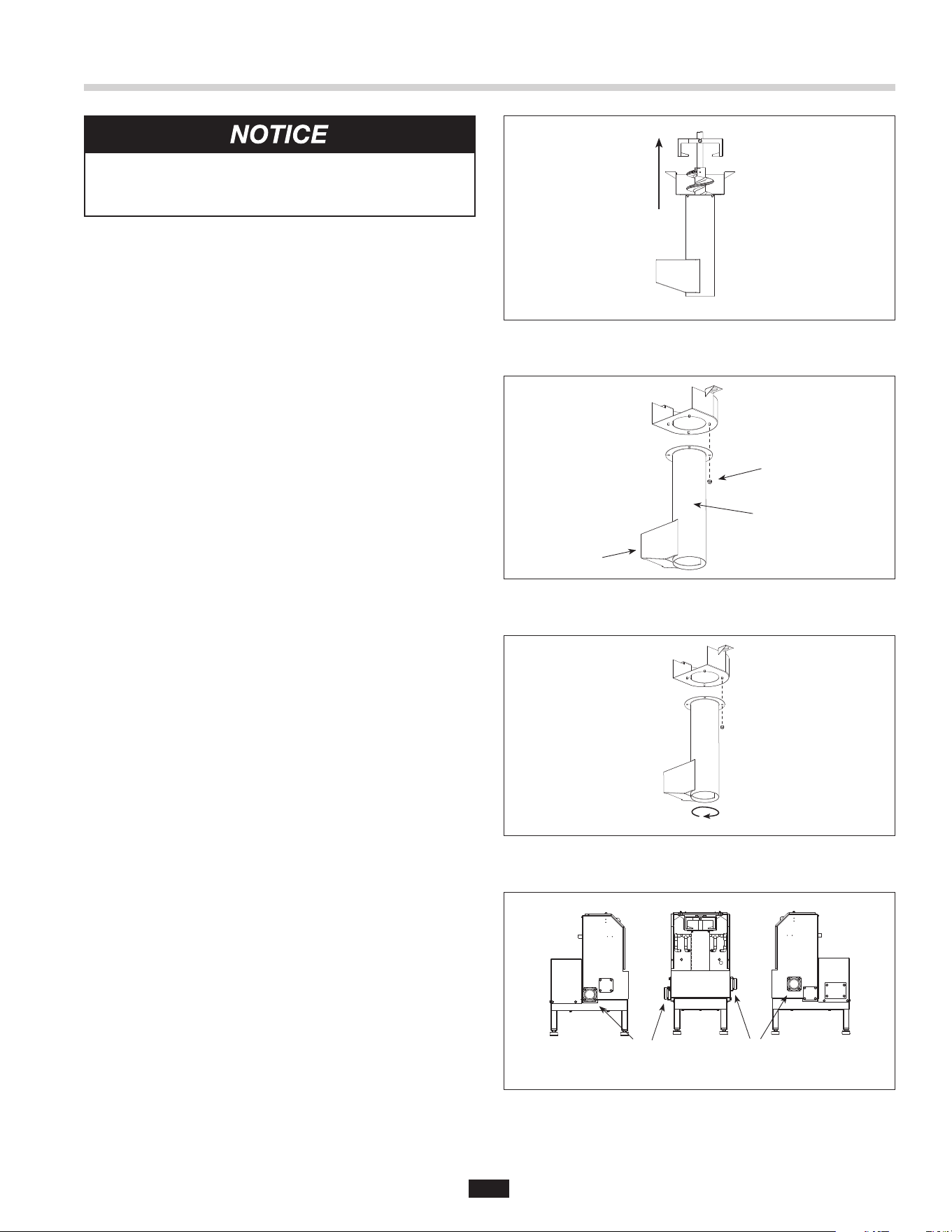
TO CHANGE WASTE INLET OR OUTLET SIDE
ON WASTE XPRESS:
A. Remove four screws holding inlet tting and
gasket in position (see Figure 18).
B. Remove four screws holding the cap and gasket in
position (see Figure 18).
C. Install gaskets, cap and inlet tting on reverse side
and secure with appropriate screws.
TO REVERSE AUGER SCREEN:
A. Holding both handles remove discharge chute
of the Waste Xpress by tilting it upward
(see Figure 13).
B. Remove auger-bearing bracket by sliding the two
captive fasteners inward and then pull
bracket upward (see Figure 14).
C. Lift auger and screen up and then out
(see Figure 14).
D. Remove auger from screen by lifting up
(see Figure 15).
E. Remove four nuts and washers holding the top
portion of the auger screen to the bottom portion
(see Figure 16).
F. Rotate bottom portion of the auger screen 180°
and secure to top portion with four nuts and
washers (see Figure 17).
Figure 15.
Figure 16.
Figure 17.
Plumbing Connections
Nuts &
Washer (4)
Auger
Screen
Inlet
Figure 18.
Waste
Outlet
Waste
Inlet
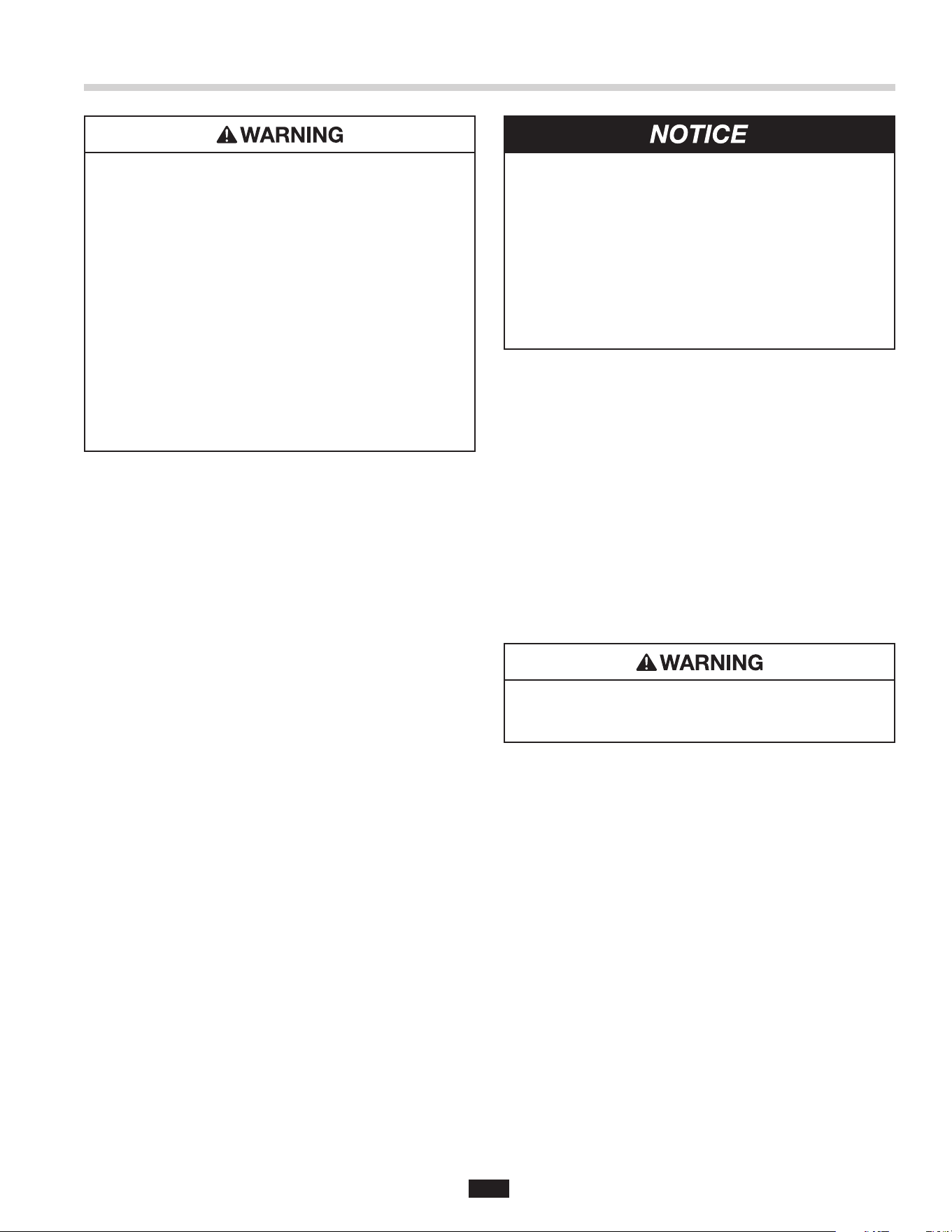
PROPERTY DAMAGE
Water connections must comply with all local
plumbing codes.
12
PROPERTY DAMAGE
System has hot water spray that must be
connected. Fresh water connection to the
Waste Xpress must be hot water only. Failure
to use hot water may clog system and result
in malfunction.
WASTE OUTLET LINE
Connect a 2" drain line to the Waste Xpress waste
outlet as specied per local codes (see Figure 18
for water outlet location).
InSinkErator recommends that the waste outlet
empties into a oor drain.
If the waste outlet connection on the Waste Xpress
needs to be switched to the other side, complete
the following:
• Remove the four screws holding the cap and gasket
in position (see Figure 18).
• Install gasket, cap and inlet tting on reverse side
and secure with appropriate screws.
NOTE: The Waste Xpress system should not be
plumbed directly into a small inside grease trap.
The unit can be plumbed through a large exterior
grease trap.
WATER SUPPLY CONNECTIONS
When connecting the incoming water supply to the
disposer, sink bowl and Waste Xpress, use as few
elbows and tees as possible.
All cold water line ttings are 1/2" NPT except the
sink bowl nozzles which are 1/2" compression.
Use 1/2" compression tting to connect hot water
to Waste Xpress.
Install the ow control valve, water solenoid valve,
and syphon breaker according to the direction of the
arrows marked on each valve body.
NOTE: In-line hot and cold shutoff valves are
recommended close to the Waste Xpress system
for ease of service.
ROUTING WATER FLOW
Connect cold water only to disposer, bowl, or trough.
Connect hot water only to Waste Xpress for hot water
spray nozzles.
In a trough system, route all water ow to the end of
the trough to ush food waste. It is also recommended
to utilize both drain outlets.
Figure 19. Typical Installation Diagram
PLUMBING CONNECTIONS
The syphon breaker is supplied with all Waste Xpress
systems (packed separately).
Syphon breaker must be installed above the sink ood
plane per local plumbing codes. Check direction of
water ow arrows.
The solenoid valve is supplied with a 24 V coil.
• The ow control valve regulates all cold water
owing into the disposer and Waste Xpress.
This conserves water and prevents overloading.
Plumbing Connections
Flow Control Valve
Disposer
Sink Bowl
Syphon Breaker
Cold Water SolenoidHot Water SolenoidWaste Xpress
Shut Off Valve
(supplied
by others)
WX-101A Controller
10 max
(3.1 m max)
1-1/2" min
(38.1 mm
min)
1" min
(25.4 mm min)
13
PROPERTY DAMAGE
• Ensure that control center voltage and phase
match the disposer motor and electrical supply.
Check nameplates on disposer and control
center for voltage and phase specications.
• Refer to the control center wiring diagrams in
this manual for correct connection.
• Use NEMA 4 watertight electrical connectors
(not supplied) when making electrical connections
to the control center.
ELECTRICAL SHOCK
• Turn off all electrical supply to the disposer before
attempting any work on it. Use a voltmeter or
circuit tester to ensure that power is off.
• All Installation work must conform to local
plumbing and electrical codes.
• All components (disposer, WX, control center
and solenoids) must be carefully and permanently
grounded.
• A properly fused disconnect must be installed at
the electrical supply source for the control center.
• The control center’s door disconnect must be in the
off position before the panel door can be opened.
Power is still present at the disconnect until power
is turned off at the electrical supply source.
LINE VOLTAGE
Connect the incoming line power to the electrical
disconnect switch and connect the disposer motor to
labeled terminal blocks in the control center. Use the
appropriate voltage and phase wiring diagram(s) in
the Wiring Diagram section at the end of this manual.
A wiring diagram is also located on the inside door of
the control center. Wire the disposer motor for correct
voltage using the connection diagram inside the motor
terminal box.
LOW VOLTAGE
The WX-101A control center uses low voltage (24 V)
to operate contactor coils, solid state control circuit,
push buttons, and solenoid valves. Red wires denote
a 24 V circuit.
COLD WATER SOLENOID VALVE
One 24 V cold water solenoid valve is supplied with
control centers. Connect solenoid valve to terminals 4
and 13. Supplied ow control valve is to be connected
to cold water line.
Wire per local electrical code using NEMA 4 water-tight
electrical connections.
HOT WATER SOLENOID VALVE
One 24 V hot water solenoid valve is supplied with
control centers. Connect solenoid valve to terminals 7
and 18. No ow control valve is to be used on hot water
line. Use 1/2" compression tting to connect hot water
line to Waste Xpress.
PERSONAL INJURY
Disconnect electricity at line disconnect switch
before servicing system.
Electrical Connections
14
PRE-OPERATION TEST
Before operating the Waste Xpress complete
the following steps to ensure the unit has been
properly installed.
1. Ensure plumbing and electrical connections
are secure.
2. Turn on incoming cold water supply to disposer
and hot water supply to the Waste Xpress.
3. Check to make sure auger and screen are seated on
auger drive hub, positioned correctly, and fasteners
on upper bearing bracket are installed and engaged
correctly prior to starting.
4. Ensure that the discharge chute is tted securely
in position.
5. Turn on incoming power to disposer and
Waste Xpress.
NOTE: Use of the electrical door disconnect knob on
the WX-101A control panel will result in a 30 second
delay before the system can be restarted. You must
wait 30 seconds after reactivation of the line disconnect
switch before system will restart.
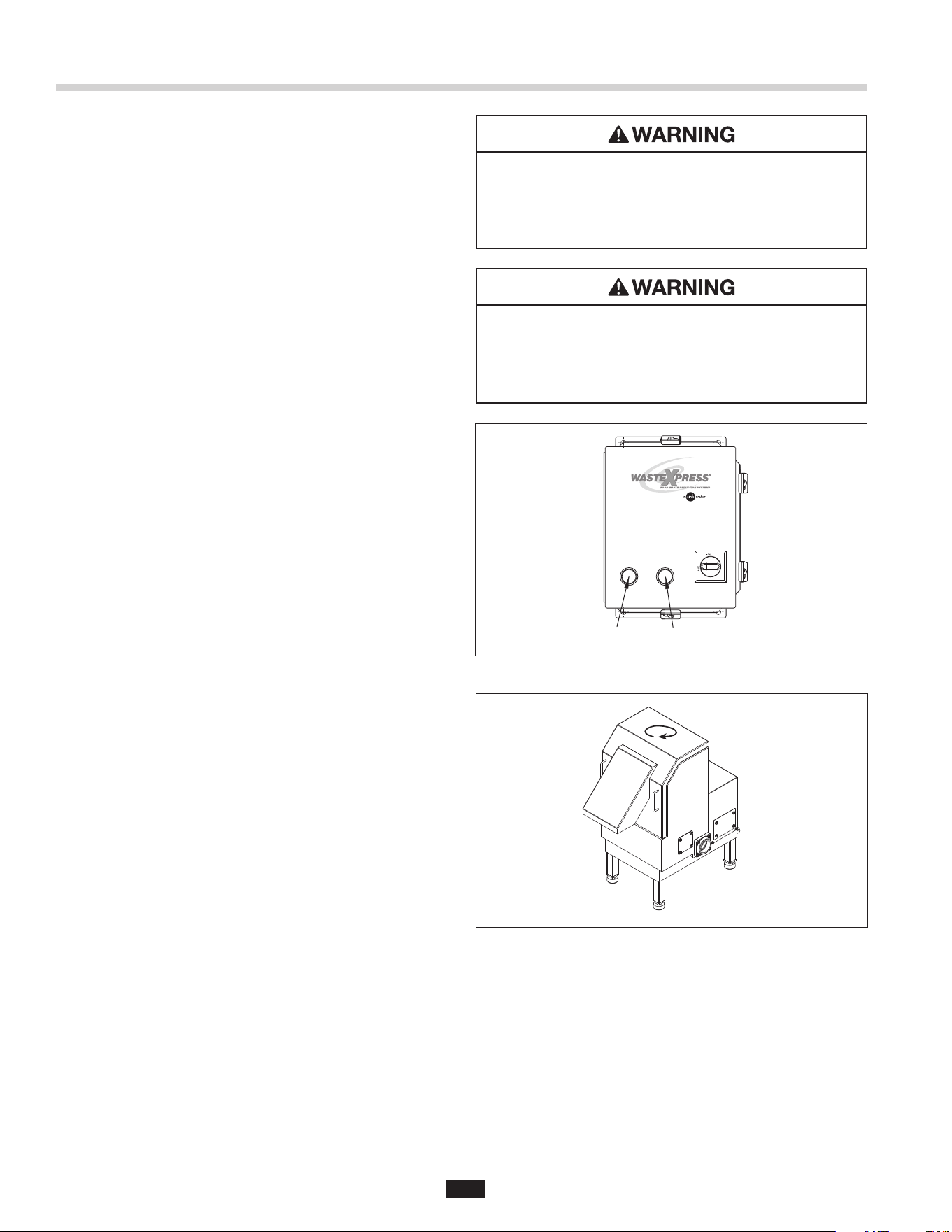
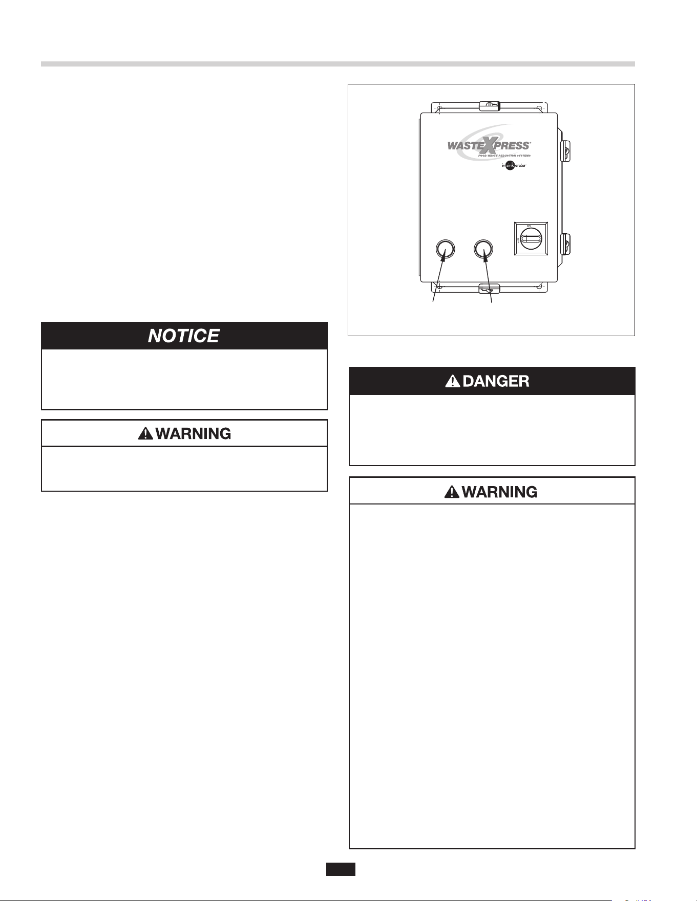
6. Push start button on the control center
(see Figure 20). The WX-101A and disposer will run
and cold water will ow into the disposer.
7. Observe auger rotation by looking up into discharge
chute; auger should rotate clockwise (when viewed
from above). See Figure 21.
NOTE: If auger rotates counter-clockwise, turn off main
power supply, wait 60 seconds, then restart. If auger
continues to rotate counter-clockwise (when viewed
from above), unit must be re-wired. Turn off main
power. On three phase Waste Xpress interchange leads
L1 and L2. Restart.
8. Make sure cold water is owing into disposer.
9. Make sure hot water to Waste Xpress spray nozzles
is cycling. Factory set cycle is 10 seconds on and
2 minutes off.
10. Press stop button to stop disposer and
Waste Xpress. Steam from chute should be evident.
11. Restart system and remove front cover/discharge
chute. Waste Xpress and disposer should turn
off automatically if interlock switch is functioning
properly. Water will continue to ow into disposer.
12. Replace front cover/discharge chute and
restart system.
Operating Instructions
ELECTRICAL SHOCK
Turn off electrical supply to Waste Xpress, control
center and disposer before attempting to work on
it. Test with a volt meter or circuit tester to insure
that power is off.
Figure 20.
Figure 21.
Rotation of Auger
Start Stop
PERSONAL INJURY
If system does not shut down when front
cover/discharge chute is removed, interlock may
not be wired correctly. See Troubleshooting section
for corrective action.
15
TO START
1. Check to ensure disposer is free of foreign objects.
2. Ensure power is on.
3. Push start button. Disposer and Waste Xpress will
run and water will ow into disposer
TO STOP
1. Push stop button. System will stop.
2. Water may continue to ow into disposer for up to
10 minutes, per the time set on the water shutoff
delay timer. This post-ush clears the drain lines
of food waste.
WATER SHUTOFF DELAY ADJUSTMENT
This water shutoff delay is adjustable from 30 seconds
to 10 minutes (see Figure 23). Set water shutoff delay
for at least 2 minutes on trough systems.
PERSONAL INJURY
To adjust the water shutoff delay, disconnect the
electrical power to the control panel and open the
control center door.
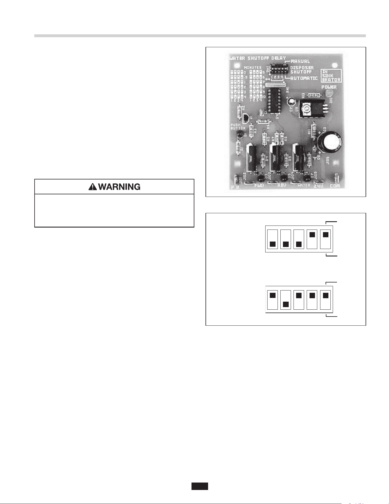
Locate the water shutoff delay at the top of the printed
circuit board in the WX-101A (see Figure 22). Set the dip
switches for the desired water shut off delay. Use the
guide printed on the circuit board to set minutes of
delay (also see Figure 23). The dip switches should be
moved to match the lled in areas of the guide.
NOTE: Line disconnect should not be turned off
between usage.
AUTOMATIC TIMED DISPOSER SHUTOFF
This water saving feature allows the system to run for
10 minutes before it automatically shuts off and must
be manually restarted.
NOTE: This feature is set in the manual position at
the factory. To activate the automatic timed system
shutoff, disconnect the electric power to the control
center, then open the control center door. Locate the
Dip Switch Module at the top of the circuit board (see
Figure 22). Move the #5 dip switch from MANUAL to
AUTOMATIC. The system now automatically shuts off
10 minutes after it starts.
30 Second Delay:
Dip Switches 1, 2,
3, pushed down,
Switch 4 pushed
up.
10 Minute Delay:
Dip Switches 1,
3, 4 pushed up
position, Switch 2
pushed down
2 3 4
1
MANUAL
AUTOMATIC
2 3 4
1
MANUAL
AUTOMATIC
30 Second Delay:
Dip Switches 1, 2,
3, pushed down,
Switch 4 pushed
up.
10 Minute Delay:
Dip Switches 1,
3, 4 pushed up
position, Switch 2
pushed down
2 3 4
1
MANUAL
AUTOMATIC
2 3 4
1
MANUAL
AUTOMATIC
Figure 22.
Figure 23. Time Delay Setting Examples
Operating Instructions
16
OPERATING WASTE XPRESS SYSTEM
1. Make sure there are no foreign objects in disposer
grind chamber. Do not pre-load disposer with food
waste prior to starting.
2. Place 10 gallon waste bin under discharge chute.
3. Push start button on control center. Waste Xpress
and disposer will run and water will ow into disposer.
4. Feed food waste into disposer in a steady,
continuous ow. Waste will exit discharge chute
and drop into waste bin.
NOTE: Once all waste has been fed into disposer, allow
approximately 2 minutes for system to clear. This will
allow system to flush itself prior to system shutdown.
5. Press Stop button to stop system.
PROPERTY DAMAGE
Do not insert: string, metal, glass, cans, silverware,
dishes, cloth napkins or large quantities of grease
or oil into the disposer.
PERSONAL INJURY
Do not dispose of hot liquids such as grease, oil
and syrup into disposer.
OPERATIONAL TIPS
• Ensure a steady stream of cold water runs into the
disposer while it is operating.
• Do not overload the disposer or turn it off with food
waste inside the grind chamber (run the disposer
and water for three minutes after the nal load to
ush away all food waste).
• Clean auger and auger screen, bearing bracket, and
discharge chute daily by running through dishwasher.
Figure 24.
Operating Instructions
StopStart
FIRE HAZARD
To minimize the possibility of re, do not store
ammable items near the disposer. Do not use
or store gasoline or other ammable liquids near
the disposer.
PERSONAL INJURY
• To reduce the risk of injury from materials that may
be expelled from the disposer grind chamber,
ensure that the disposer bafe is properly installed.
• To prevent the ejection of food waste and to keep
foreign materials out of the grind chamber, replace
the splash bafe when it becomes worn.
• Do not put any of the following items into the
disposer: clam or oyster shells, drain cleaner, glass,
china, plastic wrap, large bones, metal objects,
explosive materials, extremely hot water, grease,
oil, or syrup.
• Turn the power off before attempting to clear a jam,
remove an object, or press the reset button.
• Do not insert your ngers into the disposer. Use
long-handled tongs or pliers to remove objects
from the disposer.
• Loosen any jams with the dejamming bar.
• Be certain that all persons who will operate the
disposer read the safety and operating instructions
prior to operating the disposer.
• To prevent accidents, ensure that the disposer is
turned off before your leave the area.
17
PERSONAL INJURY
Wait until auger paddles stop before cleaning
Waste Xpress.
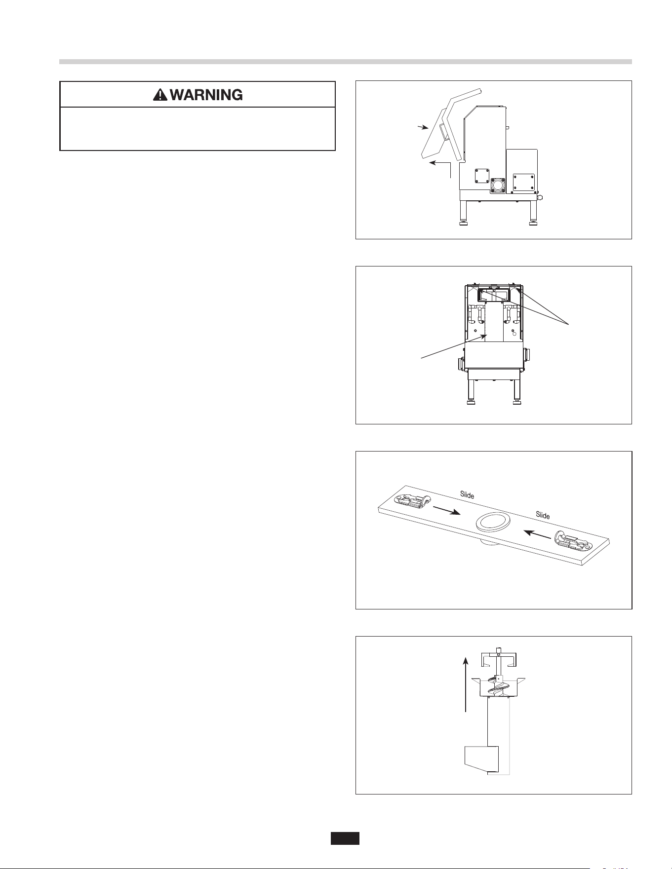
1. Press stop button on control center to stop system
(disposer & Waste Xpress).
2. Holding both handles remove discharge chute by
tilting it upward (see Figure 25).
3. Remove auger-bearing bracket by sliding the two
captive fasteners inward and then pull bracket
upward (see Figure 26 and 27).
4. Lift auger and screen up and then out
(see Figure 26).
5. Remove auger from screen by lifting it up and out
(see Figure 28).
6. Rinse auger, screen, auger compartment and
discharge chute. Auger, screen and discharge
chute are dishwasher safe and should be washed
daily. Flush inlet and outlet with a fresh water
supply to keep the drain lines clean.
7. Install auger into screen then place screen
over drive.
8. Ensure that the auger drops into position.
9. Secure bearing bracket with captive fasteners.
10. Install discharge chute by placing bottom, front
portion in rst and then tilting back and downward.
Figure 25.
Figure 26.
Figure 27. Bearing Bracket
Figure 28.
Cleaning Instructions
Discharge
Chute
Auger Screen
Captive
Fasteners
18
ELECTRICAL SHOCK
• Disconnect power before servicing.
• Do not bypass interlock switch.
PERSONAL INJURY
Wait until auger paddles stop before servicing
Waste Xpress.
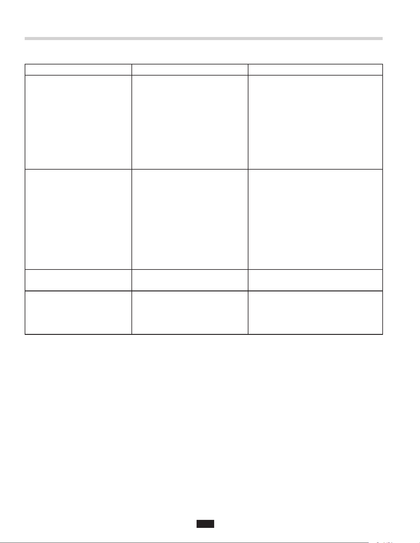
Troubleshooting for problems other than what is listed below should be performed by a qualied service person.
Troubleshooting performed by untrained personnel could result in electrical shock or damage to the Waste Xpress,
disposer and/or Control Center.
PROBLEM POSSIBLE CAUSE SOLUTION
The Waste Xpress, disposer and
water do not turn on.
• Electrical supply turned off.
• Fuse blown or circuit breaker
tripped at power supply.
• Discharge chute of Waste Xpress
not seated properly.
• Waste blocking safety interlock.
• Control circuit fuse (FNA2) blown.
• 24 V power from control center
not present.
• Line Disconnect switch on control
not in the "on" position.
• Line Disconnect switch on control
is defective.
• Start switch on control center
is defective.
• Stop switch on control center
is defective.
• Dip switch settings on circuit board
in control center may not be to
specication.
• Turn on electrical supply.
• Replace fuse or reset circuit breaker.
• Reinstall chute to ensure proper t.
• Remove waste from safety interlock.
• Replace fuse.
• Call for service.
• Turn to "on" position. Wait 15-20 seconds
before attempting at starting system to
allow control to perform "self test."
• Call for service.
• Call for service.
• Call for service.
• Call for service.
The disposer will not start or stops
while grinding, but the Waste
Xpress and water operate properly.
• The disposer overload
protector tripped.
• The disposer jammed.
• Press stop button on control center and
press red reset button on disposer.
Note: Button should be depressed until it
"clicks." You may need to let disposer cool
down before setting.
• Press stop button on control center and
follow direction for dejamming
(supplied with disposer).
The Waste Xpress, disposer and
water appear to run however
no solid waste is ejected from
the discharge chute of the
Waste Xpress.
• Auger is not sufciently primed with
waste after cleaning.
• Insufcient waste in waste line.
• Auger screen is not orientated
correctly (discharge pan opening is
facing back wall of cabinet - all
waste is falling into cabinet and
exiting unit via drain).
• Auger turning in wrong direction.
• Allow unit to run longer to prime itself.
• Waste will exit when more waste is added.
• Reverse auger screen orientation 180°.
Pan opening must face front of machine
and screen intake must t over waste inlet
on side of cabinet.
• Three phase - switch leads L1 and L2.
SYSTEM TROUBLESHOOTING
Troubleshooting
19
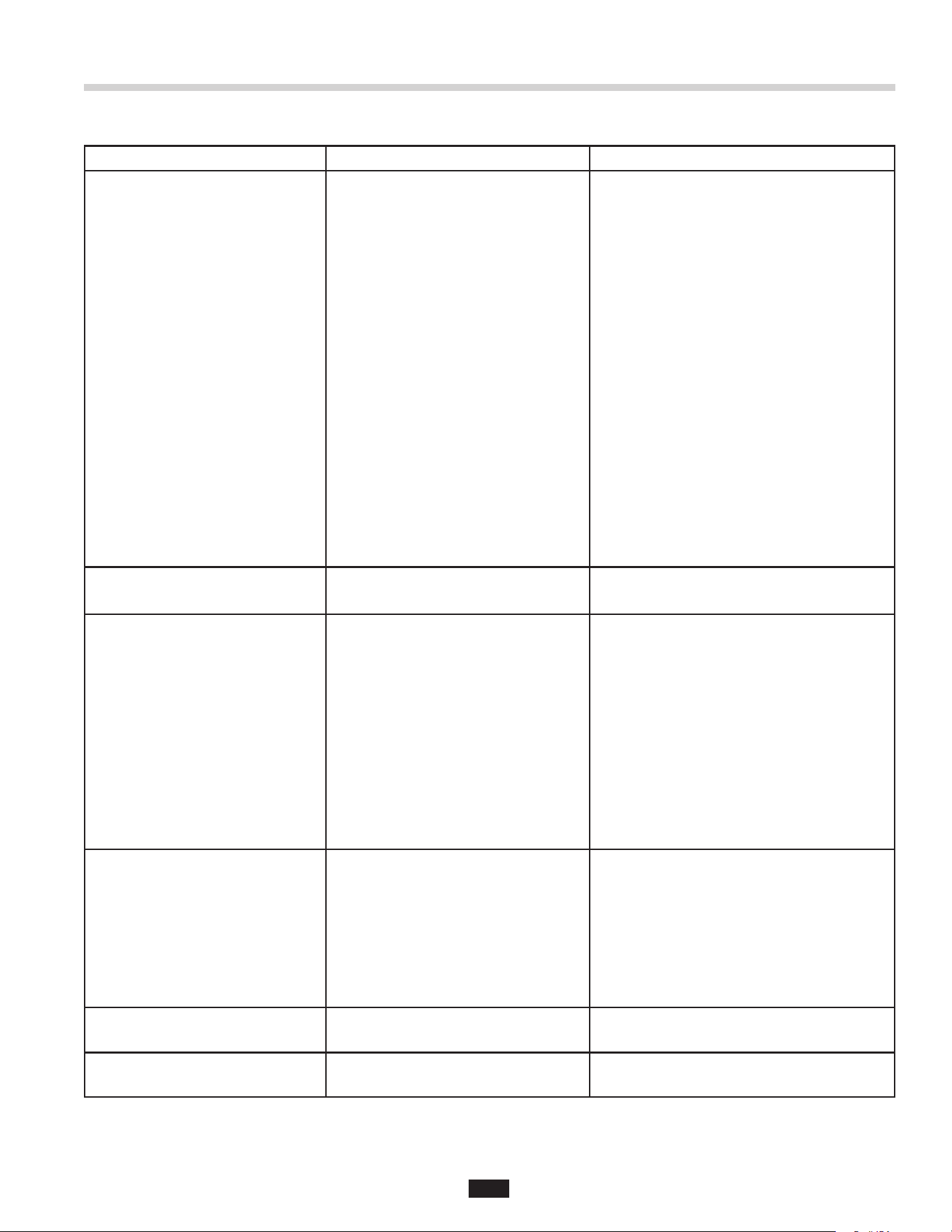
PROBLEM POSSIBLE CAUSE SOLUTION
Water backs up into disposer
(does not drain).
• The auger and screen plugged.
• Auger not turning.
• Plumbing line between disposer and
Waste Xpress clogged.
• Remove plug.
• Ensure that auger is seated properly and
that auger belt in place. Check motor.
• Remove clog.
Waste Xpress, disposer and water
will start when "start" button is
pushed but shuts down when start
button is released.
• Insufcient time allowed after Line
Disconnect switch on control center
is turned to the "on" position
• 24 V power from control center
(control circuit) is low or not present.
• Mechanical interlock on disposer
reversing contactors is defective.
• Allow 15-20 seconds prior to attempting
system start up (at start switch) after
turning Line Disconnect switch to the
"on" position.
• Call for service.
• Call for service.
Waste Xpress stops unexpectedly. • Discharge chute misaligned.
• Fuse blown or circuit breaker tripped
at power source.
• 24V power from control center
(control circuit) is low or not present.
• Operation mode on circuit board in
control center is set for 10 minute
automatic shutdown.
• Stop button on control center has
been pushed.
• Line Disconnect switch has been
turned to "off" position.
• Reinstall discharge chute to ensure
proper t.
• Replace fuse or reset circuit breaker.
• Call for service.
• Call for service.
• Push start button on control center.
• Turn to "on" position. Wait 15-20 seconds
before attempting at starting system to
allow control to perform "self test".
Note: Line Disconnect switch is only
intended for use in the event of control
center servicing.
Water exits Waste Xpress
at front of cabinet.
• Drain line has clog.
• High water level.
• Clear drain.
• Add second waste outlet drain connect from
Waste Xpress cabinet to sewer connection
(recommended for trough applications).
• Verify system has 5 gpm ow control and
shut off valve installed. Install if missing.
Waste Xpress does not run,
but disposer and water run.
• Contactor defective.
• Waste Xpress overload will not reset.
• Auger motor defective.
• Call for service.
• Call for service.
• Call for service.
Disposer and Waste Xpress will not
start, but cold water runs.
• Incoming power to WX-101A
is miswired.
• Verify/correct - 3 incoming power
leads from breaker panel must be
connected to L1-L3 on incoming side
of Line Disconnect Switch.
SYSTEM TROUBLESHOOTING
Troubleshooting
20
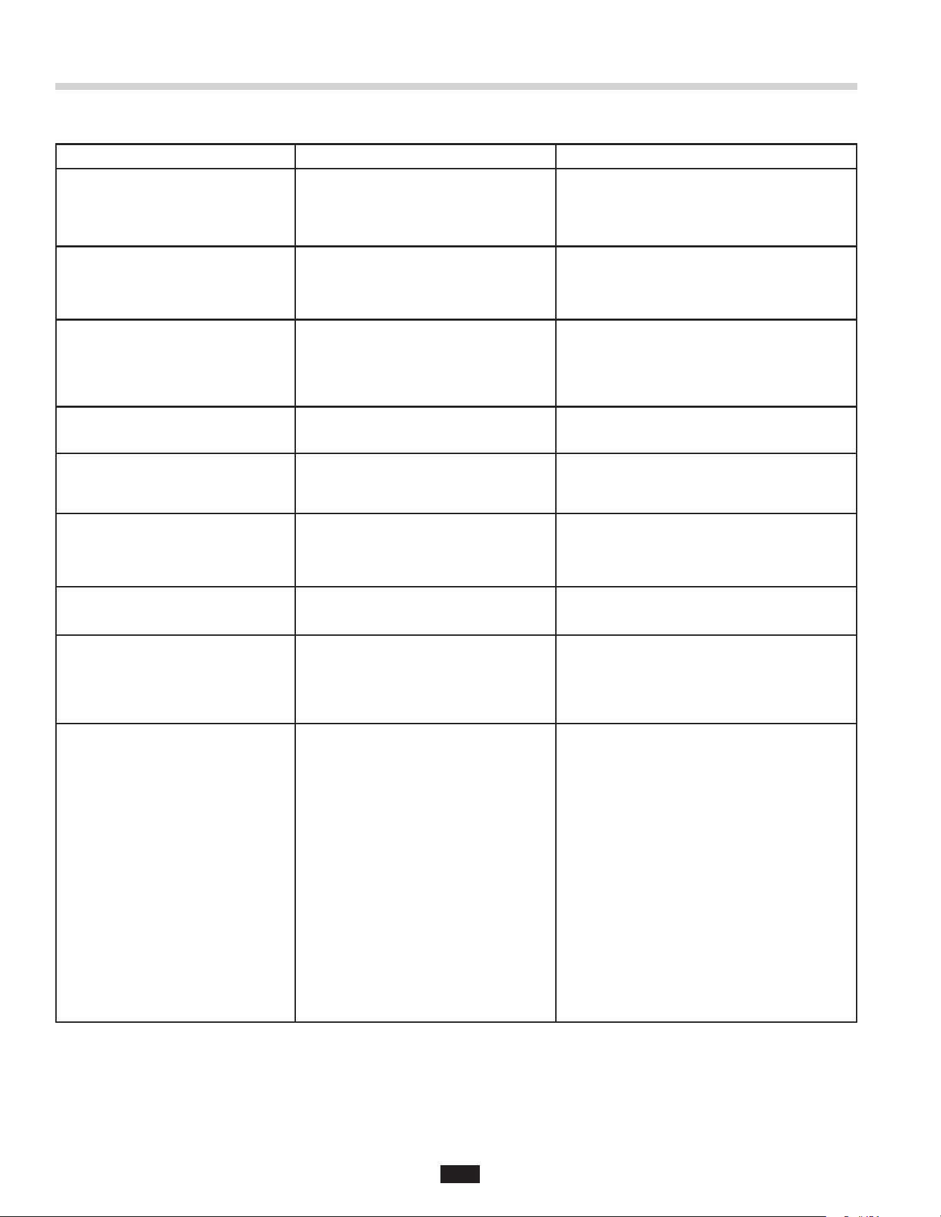
PROBLEM POSSIBLE CAUSE SOLUTION
No water spraying onto
auger screen.
• Solenoid valve clogged.
• Water turned off.
• Solenoid valve defective.
• Spray nozzles clogged.
• Timer defective.
• Timer not set properly.
• Solenoid valve installed incorrectly.
• Remove clog.
• Turn on water.
• Call for service.
• Replace nozzles.
• Call for service.
• Call for service.
• Reinstall solenoid valve so arrow is pointing
in correct direction.
Water ows continuously before
controls are turned on.
• Solenoid valve is stuck open.
• Solenoid valve installed incorrectly.
• Solenoid valve is wired incorrectly.
• Timer is defective.
• Timer is not set properly.
• Solenoid valve is defective.
• Post ush setting in control center
is not correct.
• Call for service.
• Reinstall the water solenoid valve with the
arrow on the valve pointing in the direction
of the water ow.
• Call for service.
• Call for service.
• Call for service.
• Replace solenoid valve.
• Call for service.
Overload protector trips frequently. • Disposer is overloaded with
food waste.
• Do not overload disposer with excessive
amounts of food waste.
Cold water shuts off when Waste
Xpress shuts off.
• System being shut down using Line
Disconnect switch on control center.
• Post Flush settings on circuit board in
control center are not to specication.
• Use stop and start push buttons. Line
Disconnect switch is only de-activated
when system maintenance is required.
• Call for service.
SYSTEM TROUBLESHOOTING
Troubleshooting
21
Troubleshooting
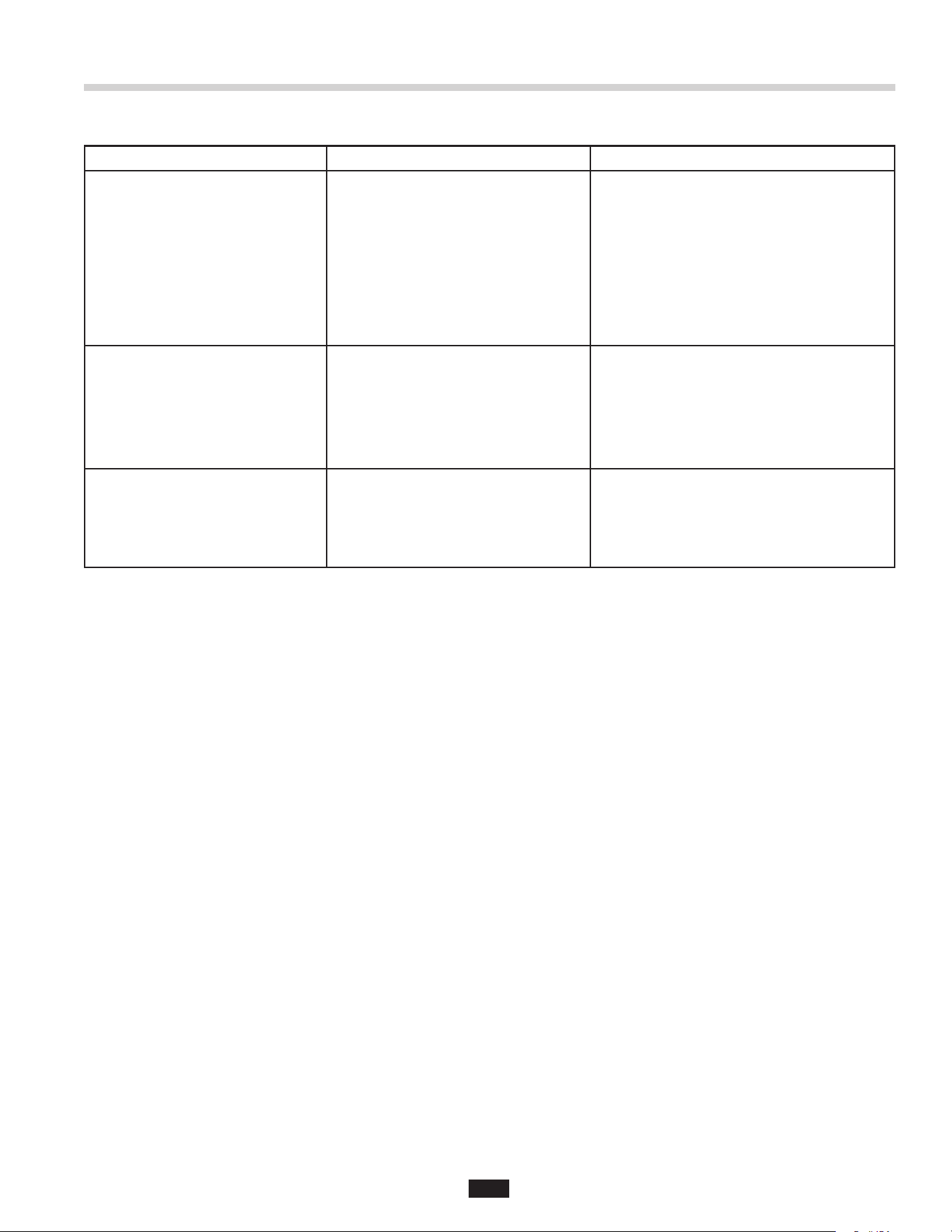
PROBLEM CAUSE SOLUTION
Disposer motor will not start and
water does not ow.
• No incoming line power.
• Line disconnect switch is not on.
• Line disconnect switch has been
reactivated and 30-second delay
has not yet expired.
• Line Disconnect switch on control
is defective.
• Start switch on control
is defective.
• Stop switch on control
is defective.
• Dip switch settings on circuit
board in control center may not be
to specication.
• Control circuit fuse FNA2 is blown.
• 24 V power from control center
(control circuit) is low or not present.
• Turn line power on.
• Turn line disconnect to "on" position. Wait
15-20 seconds before attempting to start
system to allow control to perform "self test."
• Wait 30 seconds and try starting again.
• Call for service.
• Call for service.
• Call for service.
• Call for service.
• Replace fuse.
• Call for service.
Disposer does not reverse direction. • Control center has been reactivated
before post-ush delay has expired.
• Wait until post-ush is complete and
try again.
Disposer motor stops while grinding
but water continues to ow.
• Control center wired for
automatic shut-off.
• Disposer is jammed.
• Disposer motor overload protector
has tripped.
• Press start button. If disposer runs for
10 minutes then shuts off, the automatic
shutoff is active. If the manual setting is
desired, change indicated in the
feature section.
• Press stop button and follow directions for
dejamming in disposer installation manual.
• Press stop button. Locate red reset button
on front of disposer electrical cover.
Press to reset. If motor had been running,
wait ve minutes for the motor and overload
to cool down.
Disposer will not start but
water ows.
• Overload protector on the disposer
may have tripped.
• Disposer is jammed.
• Press stop button. Locate red reset button
on front of disposer electrical cover. Press
to reset. If motor had been running, wait
ve minutes for the motor and overload to
cool down.
• Press stop button and follow directions
for dejamming that were supplied with
the disposer.
Water ows constantly before start
button is pushed.
• Water solenoid valve is
installed backward.
• Water ow should be in the direction of the
arrow on valve.
Overload trips frequently. • Disposer overloaded. • Do not overload disposer with excess
amounts of garbage and water.
DISPOSER TROUBLESHOOTING
22
PROBLEM POSSIBLE CAUSE SOLUTION
Auger runs in counterclockwise
(CCW) direction.
• Power to auger motor reversed. • Reverse motor leads to auger motor or
switch L1 and L2 connections on Waste
Xpress terminal block. Auger must run in
clockwise direction.
Unit does not shut off with cover off
of Waste Xpress unit.
• Waste Xpress Interlock not
operating properly.
• Check interlock switch #3 and #95
connections on WX-101A to Waste Xpress.
• Call for service.
Hot water spray is cold. • Incorrectly plumbed.
• No hot water.
• Connect solenoid on Waste Xpress unit to
hot water source.
• Ensure hot water heater/source
is functioning.
Hot water spray does not work. • Incorrectly wired. • Check connections on WX-101A #7 to
WX #18.
Auger reverses direction on
each re-start.
• Waste Xpress unit auger motor
has been wired into disposer
motor circuit.
• Re-wire as shown in instructions.
Waste Xpress unit will not start. • Incorrect wiring.
• Misaligned Interlock switch on chute.
• Safety interlock switch is defective.
• Check wiring.
• Check chute for tight t.
• Call for service.
Water shuts off when unit shuts off. • Improper dip switch setting
(circuit board).
• Refer to Page 16 to refer to dip switch
setting instructions.
Repetitive "hammering" sound
coming from Waste Xpress unit
while running – no waste exiting
unit at discharge chute.
• Auger has become plugged – system
has either been "batch fed" or auger
drive system has failed. Waste buildup
causing auger to malfunction – not
engaging with auger drive correctly.
• Shut system down and clean unit.
Determine cause of plug.
Waste line clogs between disposer
and Waste Xpress unit.
• System is being "batch fed."
• System is being shut down
prematurely - not being allowed to
properly clear itself of waste.
• Auger and screen not being cleaned
properly. Waste build up has hardened
and created a clog over time.
• Auger is running in wrong rotation.
• Lack of cold water owing
through system.
• Waste mix has a high berous
content (stringy food waste
and/or cardboard).
• Feed waste at a moderate and even rate –
do not attempt to process high volume all
at one time.
• Allow system to run 3-5 minutes before
shutting the sytem down to clear itself.
• Disassemble and clean the Waste Xpress
unit a minimum of once per day.
• Call for service.
• Increase water ow to 5 gpm.
• Card board cannot be processed. Fiberous
food waste should be balanced into the
waste mix with other food waste products
WASTE XPRESS TROUBLESHOOTING
Troubleshooting
23
PROBLEM POSSIBLE CAUSE SOLUTION
Waste Xpress unit is extremely wet. • Excessive moisture in waste being
processed or high volume of liquids
being processed through system.
• No ow control valve in cold water
line – full line ow from source being
directed to system.
• Slow down feed rate of waste to disposer
while processing.
• Do not process large volumes of watery
waste by itself - balance waste mix with
other types of food waste and/or disposables
• Call for service.
Water (non-vapor) exiting discharge
chute while system is running.
• High grease content in waste mix.
Build-up on screen is not being
cleaned sufciently and is causing
a "chimney" to form. Hot water
spray cycle "on" time is insufcient
to keep screen clean affecting
water drainage.
• Call for service.
Processed waste is draining from
cabinet at outlet to sewer – no
waste exiting Waste Xpress unit at
discharge chute.
• Auger is running in wrong rotation.
• Auger screen pan is facing back
of machine – processed waste
falling into base of cabinet and
exiting at outlet.
• Call for service.
• Reverse auger screen (see Cleaning
Instructions section on page 17).
WASTE XPRESS TROUBLESHOOTING
If the Waste Xpress remains inoperative after following this troubleshooting guide, contact InSinkErator’s service department at
1-800-845-8345 for the location of the nearest approved service agency.
Troubleshooting
24
PROPERTY DAMAGE
• Ensure that the control center voltage and phase
match the disposer motor and electrical supply.
Check nameplates on disposers and control
centers for voltage and phase specication.
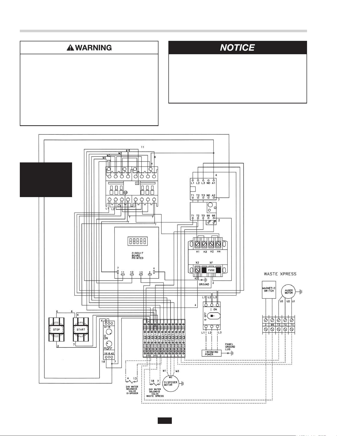
• The disposer motor wiring connection is shown in
the disposer terminal box.
120 V
1-phase
1/2 to 2 HP
WX-101A-5
208/240 V
3-phase
Call Toll Free 1-800-845-8345
for the nearest InSinkErator
Authorized Service Agency or
to reach Technical Support.
ELECTRICAL SHOCK
• Turn off the electrical supply to the disposer before
attempting any work on it. Use a voltmeter or
circuit tester to ensure that power is off.
• Installation must conform to local electrical codes.
• All components (disposer, WX, control center
and solenoids) must be carefully and permanently
grounded.
• A properly fused disconnect must be installed at
the electrical supply source for the control center.
Waste Xpress 208/240V, 3Phase System Wiring Diagram
Note: • Red wires = Low voltage (24 V) control.
• Black wires = Line voltage (208 - 240 V) control.
25
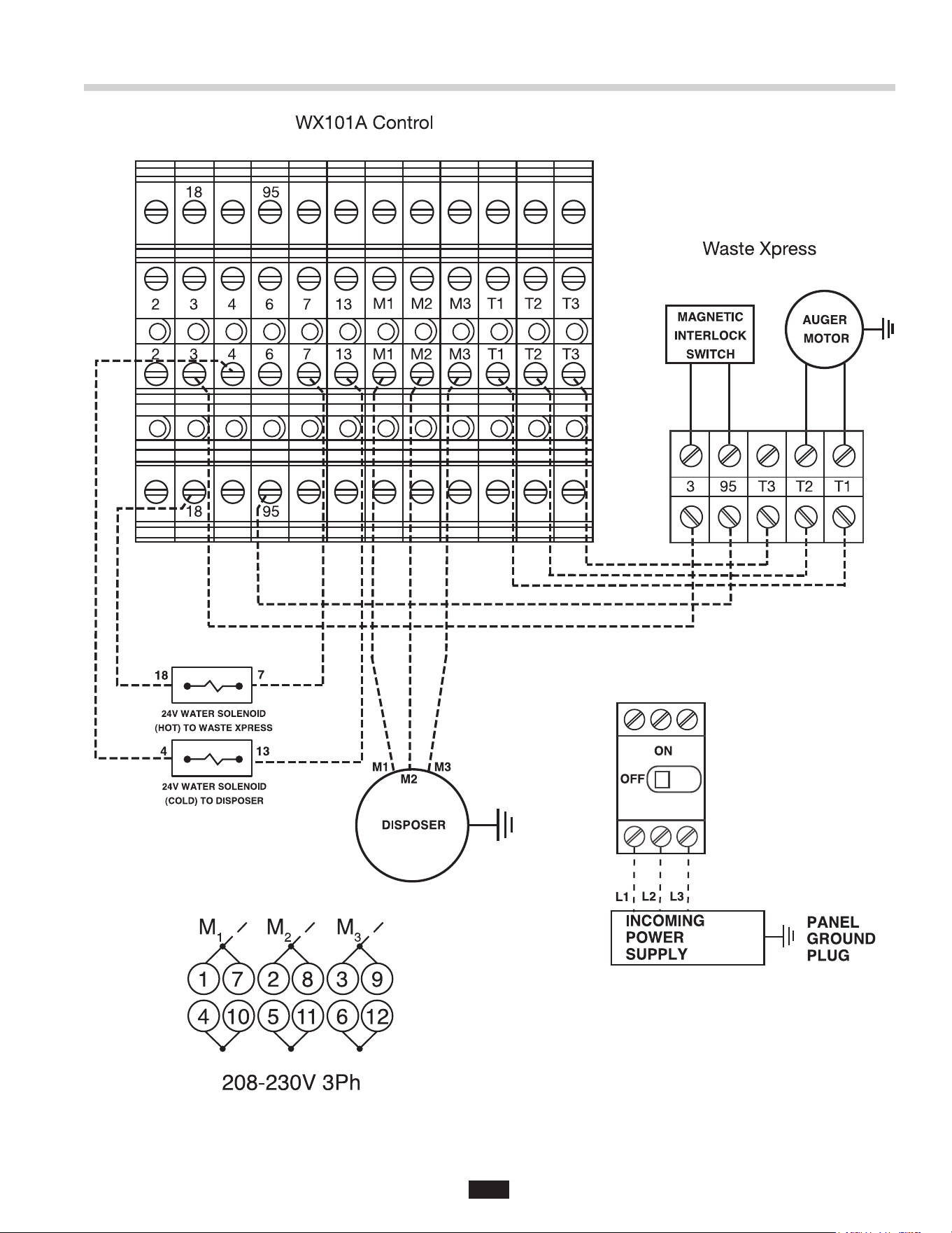
WX-101A-5 208/240V 3Phase Electrical Connections
26
PROPERTY DAMAGE
• Ensure that the control center voltage and phase
match the disposer motor and electrical supply.
Check nameplates on disposers and control
centers for voltage and phase specication.
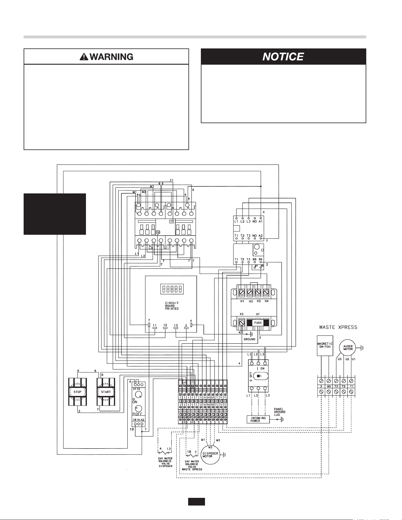
• The disposer motor wiring connection is shown in
the disposer terminal box.
120 V
1-phase
1/2 to 2 HP
WX-101A-6
380/460 V
3-phase
Call Toll Free 1-800-845-8345
for the nearest InSinkErator
Authorized Service Agency or
to reach Technical Support.
ELECTRICAL SHOCK
• Turn off the electrical supply to the disposer before
attempting any work on it. Use a voltmeter or
circuit tester to ensure that power is off.
• Installation must conform to local electrical codes.
• All components (disposer, WX, control center
and solenoids) must be carefully and permanently
grounded.
• A properly fused disconnect must be installed at
the electrical supply source for the control center.
Waste Xpress 380/460V, 3Phase System Wiring Diagram
Note: • Red wires = Low voltage (24 V) control.
• Black wires = Line voltage (380 - 460 V) control.
27
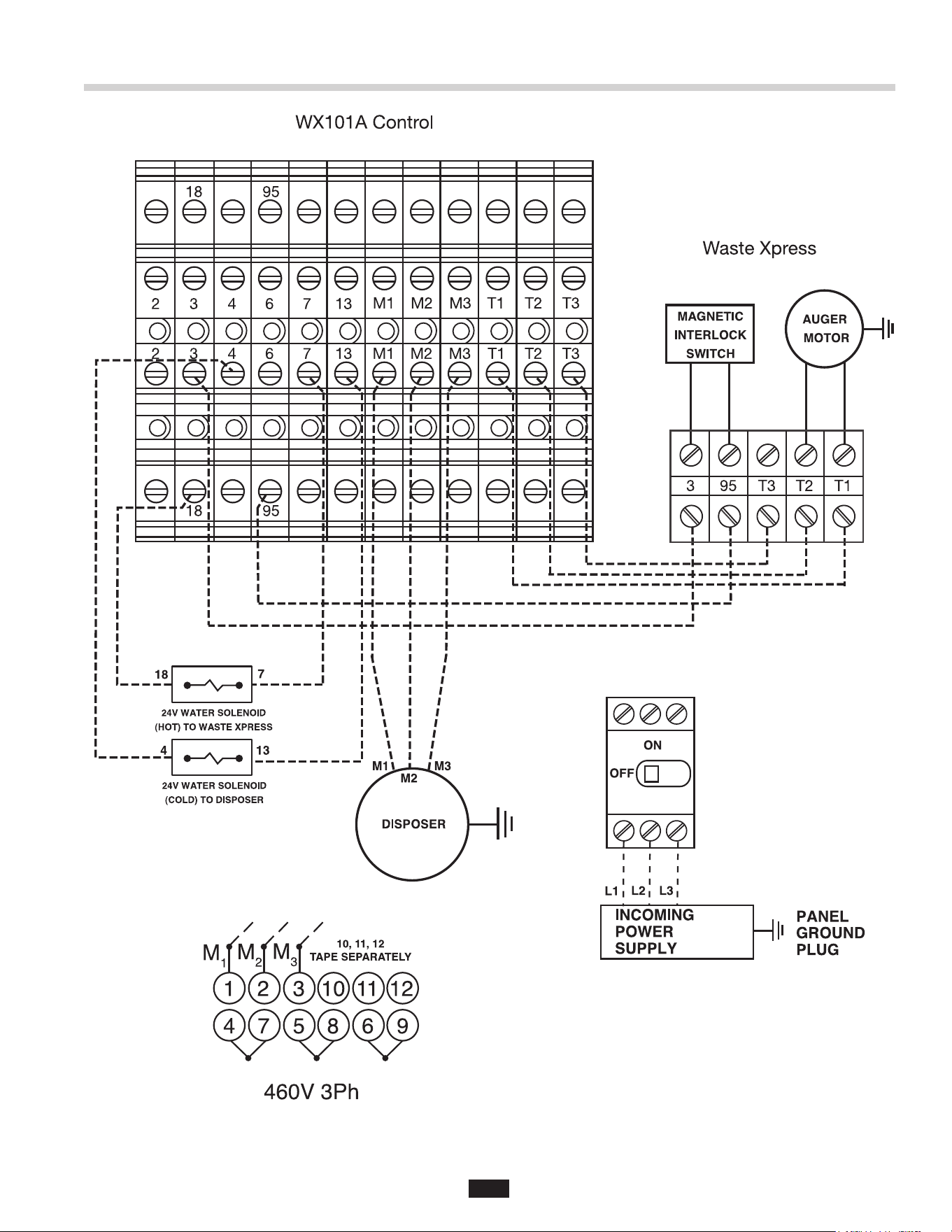
WX-101A-6 380/460V 3Phase Electrical Connections

InSinkErator® may make improvements and changes in the specication at any time, in its sole
discretion, without notice or obligation and further reserves the right to change or discontinue models.
©2023 InSinkErator®. All rights reserved.
Limited Warranty
InSinkErator® (“InSinkErator” or “Manufacturer” or “we” or “our”
or “us”) warrants to the original purchaser only (“Customer” or “you”
or “your”), subject to the exclusions below, that your InSinkErator®
(the “InSinkErator Product”) will be free from defects in material
and workmanship for one year from the original date of purchase (the
“Warranty Period”). This limited warranty terminates if the original
purchaser transfers the InSinkErator Product to any other person or
entity.
What is Covered
This limited warranty includes repair or replacement of your
InSinkErator Product, accessories if included in the original
InSinkErator Product package, and all replacement parts and labor
costs if provided by an authorized InSinkErator service representative.
What is not Covered
This limited warranty does not extend to and expressly excludes:
• Losses or damages or the inability to operate your InSinkErator
Product resulting from conditions beyond the Manufacturer’s
control including, without limitation, accident, alteration, misuse,
abuse, neglect, or negligence (other than Manufacturer’s).
• Wear and tear expected to occur during the normal course of use,
including without limitation, cosmetic rust, scratches, dents or
comparable and reasonably expected losses or damages.
• Failure to install, maintain, assemble, or mount the InSinkErator
Product in accordance with Manufacturer’s instructions or local
electrical and plumbing codes, faulty or improper electrical
installation, faulty or improper plumbing installation, clogged drain
lines, or an improperly sized unit (as specied by InSinkErator).
What we will do to Correct Problems
To le a warranty claim during the Warranty Period, you may call Toll
Free 1-800-845-8345 for the nearest InSinkErator Authorized Service
Agency or to reach Technical Support, or you may visit our website at
www.insinkerator.com.
The following information must be provided as part of your warranty
claim: your name, address, phone number, your InSinkErator Product
model and serial number. You will be required to submit supporting
documentation of the date of purchase.
Manufacturer or its authorized service representative will determine,
in its sole and absolute discretion, if your InSinkErator Product is
covered under this limited warranty. Only an authorized InSinkErator
service representative may provide warranty service. InSinkErator
is not responsible for warranty claims arising from work performed
on your InSinkErator Product by anyone other than an authorized
InSinkErator service representative.
If a covered claim is made during the Warranty Period,
Manufacturer will, through its authorized service representative,
and at Manufacturer’s or its authorized service representative’s sole
discretion, either repair or replace your InSinkErator Product. If your
InSinkErator Product is replaced, the warranty on the replacement
InSinkErator Product will be limited to the unexpired term remaining
in the original Warranty Period. YOUR SOLE AND EXCLUSIVE
REMEDY UNDER THIS LIMITED WARRANTY SHALL BE LIMITED
TO REPAIR OR REPLACEMENT OF THE INSINKERATOR
PRODUCT. This limited warranty is valid only in the United States and
applies only when the InSinkErator Product is used in the country in
which it was purchased. If outside the 50 United States, contact your
authorized InSinkErator dealer to determine whether any warranty
applies.
No Other Express Warranty Applies
THE LIMITED WARRANTIES PROVIDED ABOVE ARE THE SOLE
AND EXCLUSIVE WARRANTIES PROVIDED BY MANUFACTURER
TO THE ORIGINAL PURCHASER, AND ARE IN LIEU OF ALL
OTHER WARRANTIES, WRITTEN OR ORAL, EXPRESS OR
IMPLIED, WHETHER ARISING BY OPERATION OF LAW OR
OTHERWISE, INCLUDING, WITHOUT LIMITATION, WARRANTIES
OF MERCHANTABILITY OR FITNESS FOR A PARTICULAR
PURPOSE, WHETHER OR NOT THE PURPOSE HAS BEEN
DISCLOSED AND WHETHER OR NOT THE INSINKERATOR
PRODUCT HAS BEEN SPECIFICALLY DESIGNED OR
MANUFACTURED FOR YOUR USE OR PURPOSE.
Limitation of Liability
TO THE EXTENT PERMITTED BY LAW, IN NO EVENT
SHALL MANUFACTURER OR ITS AUTHORIZED SERVICE
REPRESENTATIVES BE LIABLE FOR ANY INCIDENTAL, SPECIAL,
INDIRECT, OR CONSEQUENTIAL DAMAGES, INCLUDING
ANY ECONOMIC LOSS, WHETHER RESULTING FROM
NONPERFORMANCE, USE, MISUSE OR INABILITY TO USE THE
INSINKERATOR PRODUCT OR THE MANUFACTURER’S OR ITS
AUTHORIZED SERVICE REPRESENTATIVE’S NEGLIGENCE.
MANUFACTURER SHALL NOT BE LIABLE FOR DAMAGES
CAUSED BY DELAY IN PERFORMANCE AND IN NO EVENT,
REGARDLESS OF THE FORM OF THE CLAIM OR CAUSE OF
ACTION (WHETHER BASED IN CONTRACT, INFRINGEMENT,
NEGLIGENCE, STRICT LIABILITY, OTHER TORT OR
OTHERWISE), SHALL MANUFACTURER'S LIABILITY TO YOU
EXCEED THE PRICE PAID BY THE ORIGINAL OWNER FOR THE
INSINKERATOR PRODUCT.
The term "consequential damages" shall include, but not be limited
to, loss of anticipated profits, business interruption, loss of use or
revenue, cost of capital or loss or damage to property or equipment.
Some states do not allow the exclusion or limitation of incidental or
consequential damages, so the above limitation may not apply to you.
This warranty gives you specific legal rights and you may also have
other rights which vary from state to state.