INSTRUCTIONS FOR USE
5-10-15 US TRAYS BLAST CHILLER
Serie “NEW RUNNER”
EVJS-824 Control panel version
BCB/05US
BCB/10US
BCB/15US
Manual BCB US Rev00 09-2024
www.gemm-srl.com

BCB US Rev.00 09-2024 pag. 2
Serial Number

BCB US Rev.00 09-2024 pag. 3
INDEX
1.
SAFETY
6
1.1 – Symbols used
1.2 – General warnings
1.3 – Residual risks
1.4 – Personnel
1.5 – Improper use
1.6 – Safety devices
1.7 – Stop functions
2.
GENERAL INFORMATION
12
2.1 – Marking
2.2 – Warranty
2.3 – After-sales service
2.4 – How to use and keep the manual
3.
MACHINE DESCRIPTION
14
3.1 – Technical data
3.2 – Description of blast chiller and it use
3.2.1 – Main parts
3.3 – Noise
3.4 – Ambient conditions
4.
TRANSPORT AND HANDLING
19
4.1 – Transport
4.2 – Handling the packed blast chiller
4.2.1 – Weight and dimensions
4.2.2 – Means requie

BCB US Rev.00 09-2024 pag. 4
5.
INSTALLATION
21
5.1 – Preparation for installation
5.2 – Unpacking
5.2.1 – Means required
5.2.2 – Unpacking procedure
5.3 – Handling the blast chiller
5.3.1 – Means required
5.3.2 – Handling the unpacked blast chiller
5.4 – Blast chiller assembly
5.5 – Removal, evacuation and charging procedures
5.6 – Recovey
6.
SETTING UP
25
6.1 – Connections
6.1.1 – Electrical connection
6.2 – Preliminary checks
6.2.1 – Regulation
7.
USE
28
7.1 – Use forseen
7.2 – Unforseen use
7.3 – Control panel
7.4 – Control procedures
7.5 – Use procedures
7.6 – Chilling and Freezinh cycle
7.7 – Hard chilling and Soft Freezing cycle
7.8 – Special uses
7.8.1 – Pre-cooling function
7.8.2 – Defrost
7.8.3 – Fish sanitization
7.8.4 – Ice cream hardening
7.8.5 – Recipes
8.
MAINTENANCE AND REPAIR
38
8.1 – Special precautions
8.2 – Routine maintenance
8.2.1 – Routine maintenance table (tab. 5)
8.2.2 – Cleaning the chamber
8.2.3 – Cleaning the outside of the appliance

BCB US Rev.00 09-2024 pag. 5
8.2.4 – Cleaning the condenser
8.2.5 – Cleaning the core probe
8.3 – Extraordinary maintenance
8.3.1 – Refrigerant equipment
8.3.2 – Electrical components
8.3.3 – Sealed components
8.3.4 – Intrnsically safe components
8.3.5 – Cabling
8.3.6 – Detection of flamable refrigerant
8.3.7 – Reoval and evacuation
8.3.8 – Charging procedures
8.3.9 – Recovery
8.4 – Operating anomalies and faults
8.4.1 – Alarms
8.4.2 – Errors
9.
DECOMISSIONING
50
10.
9.1 – Preparation for decomissioning
9.2 – Removal and evacuation
9.3 – Recovery
9.4 – Labbeling
DISPOSAL
52
10.1 – Disposal method
11.
SPARE PARTS
52
11.1 – Ordering spare parts
12.
APPENDICES
52
BCB US Rev.00 09-2024 pag. 6
1. – SAFETY
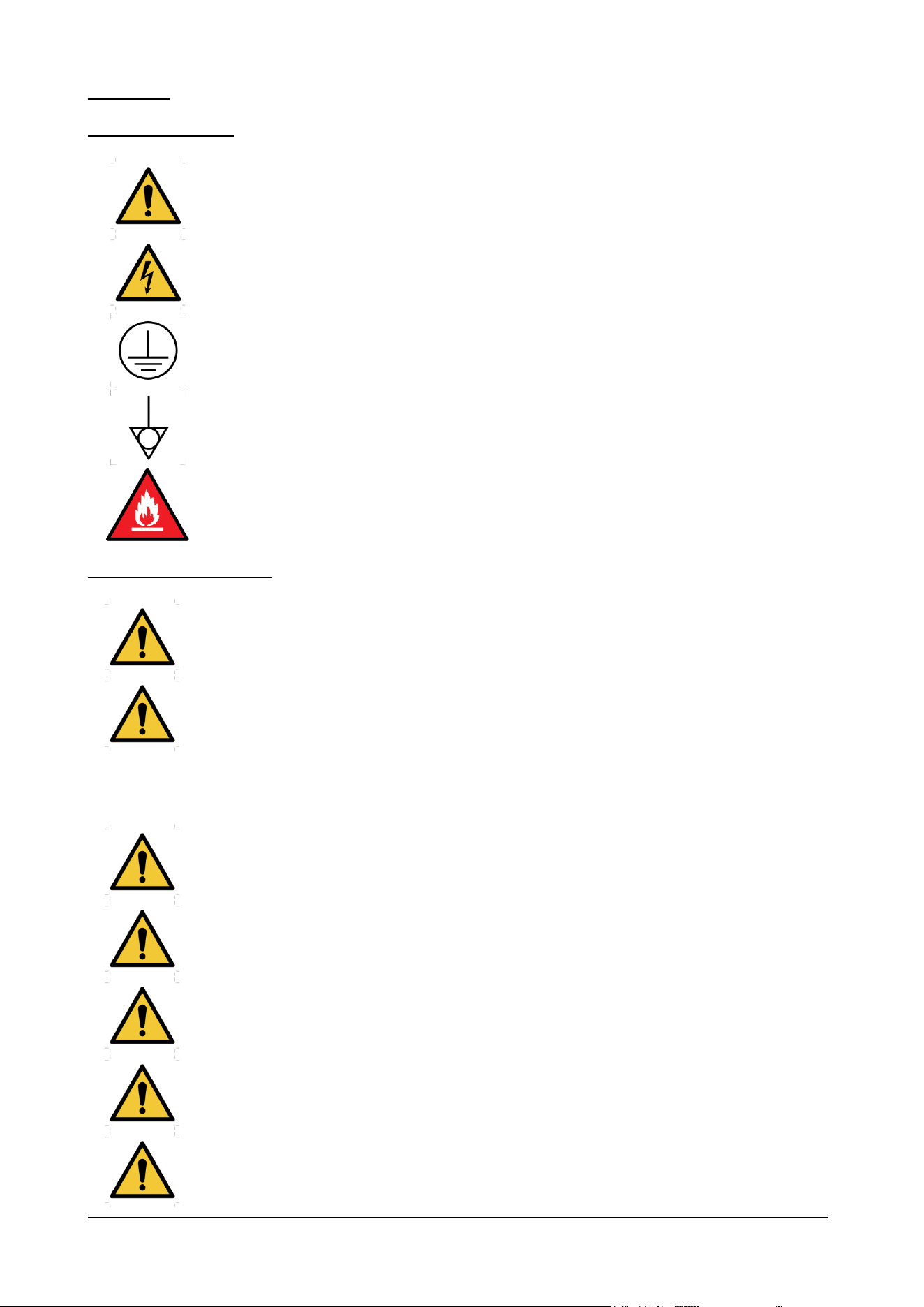
1.1 – SYMBOLS USED
This symbol indicates information and warnings which if not observed could damage the appliance or
compromise the safety of personnel.
This symbol indicates information and warnings regarding electrical devices which if not observed
could damage the appliance or compromise the safety of personnel.
To identify any terminal which is intended for connection to an external conductor for protection
against electric shock in case of a fault, or the terminal of a protective earth (ground) electrode.
To identify the terminals which, when connected together, bring the various parts of an equipment or
of a system to the same potential, not necessarily being the earth (ground) potential, e.g. for local
bonding.
This symbol indicates that the appliance uses flammable refrigerantes.
1.2 – GENERAL WARNINGS
IMPORTANT: before using the appliance read this manual carefully and follow the technical operating
instructions and indications to the letter. The operator must know the position and function of all the
control devices and the characteristics of the blast chiller.
The blast chiller complies with current safety regulations, but improper use may cause damage to
persons and things.
At the time of installation all operatives must be suitably trained in accident hazards, operator safety
devices, general accident prevention regulations described in international directives and the current
law in the countries where the appliance is used. Start-up and use of the appliance must be exclusively
in the hands of trained personnel. The behaviour of operators must in any case scrupulously observe
accident prevention regulations in the country where the appliance is used.
Do not remove or deface the plates fitted to the appliance by the manufacturer.
The blast chiller must not be used if the control panel or any other part is damaged.
Do not obstruct the front and/or rear air vents on the appliance; do not place food to be processed up
against the ventilation grilles or air ducts, or directly on the bottom of the chamber.
Promptly report any anomalies in operation.
Use only accessories recommended by the manufacturer.
BCB US Rev.00 09-2024 pag. 7
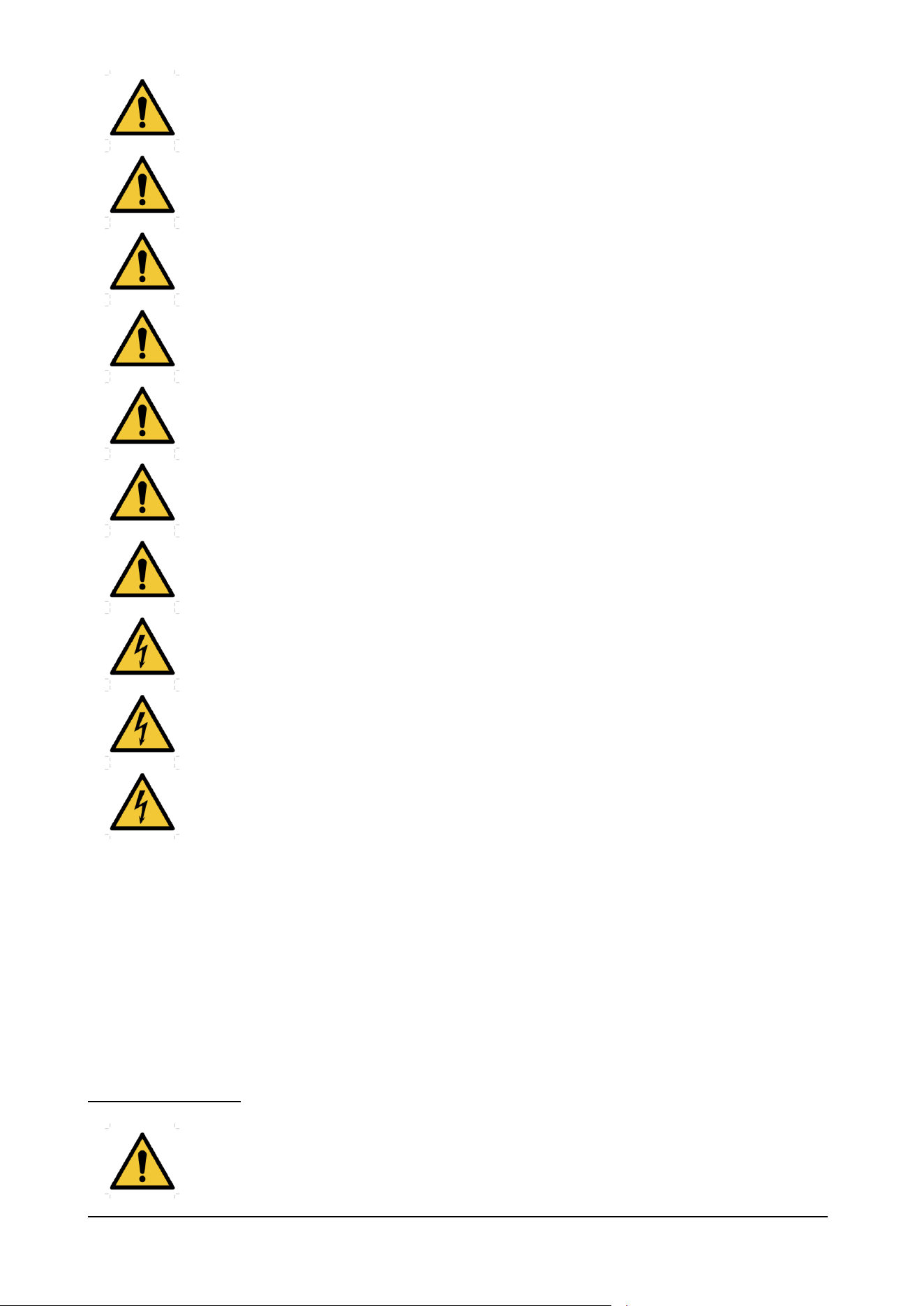
Do not store explosive substances such as aerosol cans with a flammable propellant inside the
appliance.
WARNING: Do not use mechanical devices or other means to accelerate the defrosting
process, other than those recommended by the manufacturer.
WARNING: The appliance shall be stored in a room without continuously operating ignition sources
(for example: open flames, an operating gas appliance or an operating electric heater.
WARNING: Do not pierce or burn.
WARNING: Be aware that refrigerants may not contain an odour
WARNING: Do not damage the refrigerating circuit
This appliance is not intended for use by persons (including children) with reduced physical, sensory or
mental capabilities, or lack of experience and knowledge, unless they have been given supervision or
instruction concerning use of the appliance by a person responsible for their safety. Children should be
supervised to ensure that they do not play with the appliance.
Do not expose the appliance to rain or sprays of water.
Routine and extraordinary maintenance that require the electrical box to be opened or even partial
dismantling of the blast chiller must be carried out only after the appliance has been disconnected.
If the supply cord is damaged, it must be replaced with an identical one by the manufacturer, its service
agent or similarly qualified persons in order to avoid a hazard - risk of electric shock.
The manufacturer has no responsibility in the following cases:
− the maintenance plan is not carried out;
− unauthorized alterations and/or operations:
− spare parts used are not original;
− failure to observe even part of the contents of this manual;
− improper use of the appliance.
Any tampering with or unauthorized replacement of one or more appliance parts or components and use of
accessories and consumables different from the original ones can constitute a hazard and relieve the
manufacturer of any civil or penal responsibility.
If in doubt about operation of the appliance, refrain from using it and contact the manufacturer.
1.3 – RESIDUAL RISKS
LOW TEMPERATURE BURN HAZARD
During its operation the appliance runs extremely low temperatures: avoid direct contact with
the internal parts immediately after opening the door.

BCB US Rev.00 09-2024 pag. 8
1.4 – PERSONNEL
This manual is for the use of operators, authorized fitters and maintenance engineers.
Operators must not carry out operations reserved for maintenance engineers or specialised
technicians.
The manufacturer accepts no responsibility for damage deriving from failure to observe this
rule.
- Appliance operator: specialised person who can operate the appliance in normal working conditions by using
the relevant controls. The operator must also be capable of carrying out simple routine maintenance (cleaning,
loading) and starting or resetting the appliance after a power failure.
- Specialised electrician: specialised electrician who has been trained by the manufacturer to work on the
appliance. The specialised electrician must be capable of installing the appliance and operating it in normal
conditions; s/he is qualified to carry out all electrical and mechanical adjustments, maintenance and repairs. S/he
is able to operate with live electrical control boxes and connector blocks.
- Qualified fork-lift operator: person qualified in handling materials on the company’s premises, holder of a licence
for the use of fork-lift trucks.
BCB US Rev.00 09-2024 pag. 9
1.5 – IMPROPER USE
The blast chiller must not be used:
− for purposes different from those given in paragraph 3.2 “Description of blast chiller and its use”;
− with safety systems not working;
− after badly done installation;
− by untrained personnel;
− when maintenance has not been carried out, or has been carried out badly;
− when non-original spare parts are used;
− with damaged power lead and/or electrical socket;
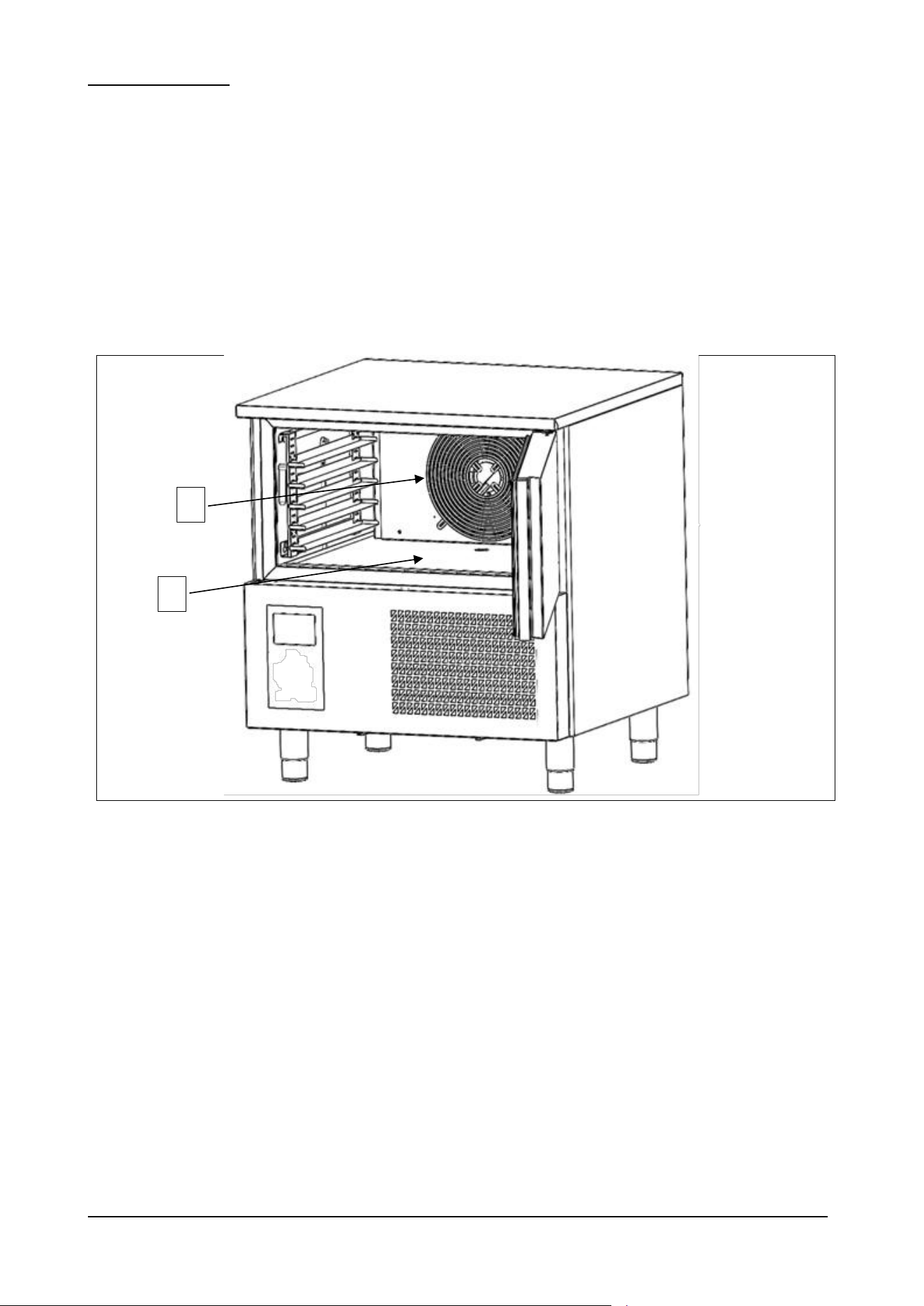
− with obstructed air ducts (ref. 1 fig. 1);
− with the food to be processed placed against the ventilation grilles (ref. 1 fig. 1), air ducts, or on the bottom of the
chamber (ref. 2 fig. 1).
Fig. 1
1
2
BCB US Rev.00 09-2024 pag. 10
1.6 – SAFETY DEVICES
Personnel exposed to the hazards inherent in moving parts are protected by special safety devices on the appliance.
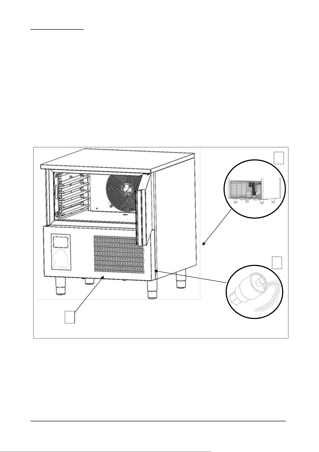
− grilles covering the cooling fans (ref. 1 fig. 2);
− grilles covering the condenser unit (ref. 2 fig. 2).
The appliance is also provided with devices to protect the food during processing. Below is a list of the safety devices on
the appliance.
− Sensor reads and signals door opening. If the doors remains open for a presetted time, it will appear on the
display the message “ DOOR OPEN ” combined with a acoustic alarm and the compressor will switch off.
− Sensor (ref. 3 fig. 2) located on cooling circuit signals any overheating of the equipment and places the machine
on standby.
− Differential magnetothermal overload relay for compressor protection: only in three phase equipment.
Fig. 2
1
3
2
BCB US Rev.00 09-2024 pag. 11
1.7 – STOP FUNCTIONS
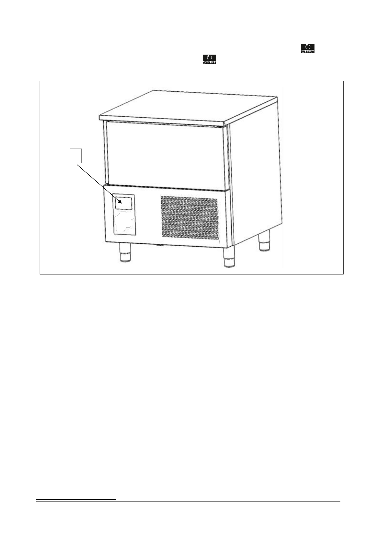
The entire appliance is controlled by an electronic circuit board. The stop function is represented by the button (ref.
1 fig. 3). Whatever condition the machine is in, holding down the button for 3 seconds sets in standby the machine.
Fig. 3
2 – GENERAL INFORMATION
1
BCB US Rev.00 09-2024 pag. 12
Thank you for choosing a blast chiller of our production.
Read this manual very carefully and make sure it is available to those who will install, use and maintain the equipment.
2.1 – MARKING
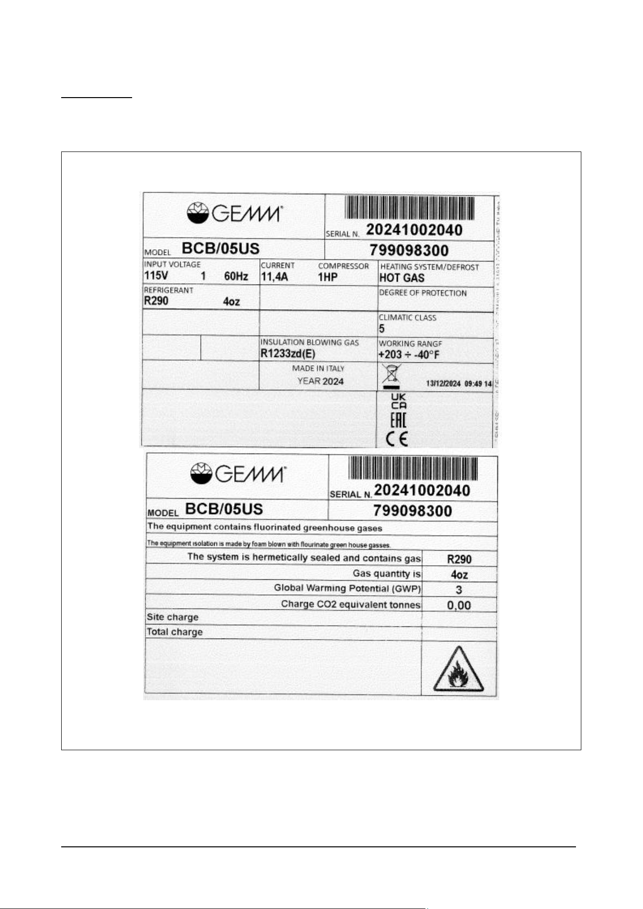
The ID plates are located on the outside of the appliance, in the bottom right-hand corner of the front: Fig. 4 below shows
copies.
Fig. 4

BCB US Rev.00 09-2024 pag. 13
2.2 – WARRANTY
The warranty covering the various parts of the appliance is valid from the date on the relative delivery note and is as
described in the sales agreement.
The warranty does not cover damage to the appliance caused by:
- transport and/or handling;
- operator errors;
- lack of the maintenance described in this manual;
- faults and/or breakages that cannot be traced to faulty operation of the appliance;
- maintenance operations carried out by unqualified personnel;
- improper use.
2.3 – AFTER-SALES SERVICE
Please contact the manufacturer directly for any needs regarding use, maintenance or ordering of spare parts, and specify
the identification of the appliance given on the ID plate.
2.4 – HOW TO USE AND KEEP THE MANUAL
The purpose of this manual is to provide all the information necessary to ensure proper use of the appliance in complete
safety and independence.
The manual is sub-divided into chapters with paragraphs and sub-paragraphs: the contents page is easily consulted to find
any aspect of interest.
The material in this document is provided exclusively for the purpose of information and may be altered without notice.
Although great attention is paid to drawing up the manual, the manufacturer is not responsible for damage deriving
from errors, omissions or the use made of the information herein.
Keep this manual and all the documentation in the appendices in good condition, legible and complete in all its parts; keep
it close to the equipment in an accessible place known to all operators.
BCB US Rev.00 09-2024 pag. 14
3 – MACHINE DESCRIPTION
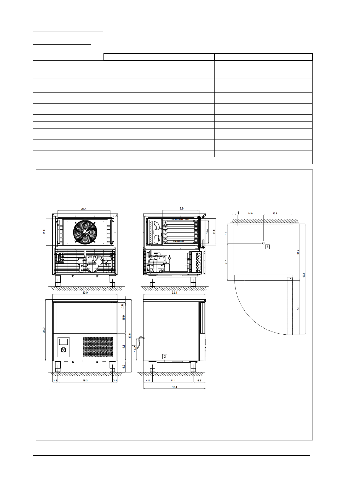
3.1 –TECHNICAL DATA
Model
BCB/05US
BCB/10US
External
dimensions
inches
33.9 X 32.4 X 37.8
33.8 X 34.7 X 61.4
Weight
lb
238
348
Trays
No.
5 (26X18'')
10 (26X18'')
Max load for trays
lb
55
55
Chamber
temperature
°F
203 / - 40
203 / - 40
Output
lb
44 (+ 149 °F ÷ + 37 °F); 26 (+ 149 °F ÷ 0 °F)
75 (+ 149 °F ÷ + 37 °F); 48.5 (+ 149 °F ÷ 0
°F)
Gas
R290
R404A
Compressor power
Hp
1
1 1/2
Max. absorbed
courrent
A
13
10
Power supply
voltage
Volt 1x115 ~ 60 Hz
Volt 1x230 ~ 60 Hz
Electricity supply
3x12AWG – NEMA 5-20P – 9ft
3x12AWG – NEMA 6-20P – 9ft
Tab. 1/a
Fig. 5/a
BCB US Rev.00 09-2024 pag. 15
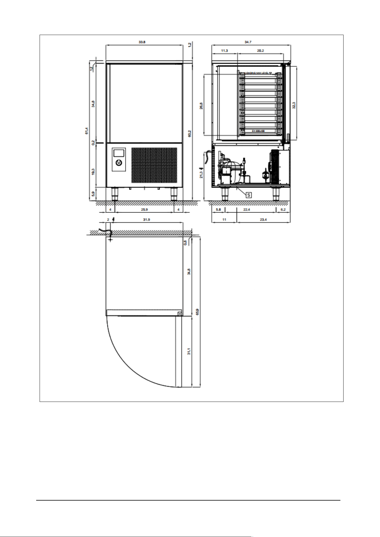
Fig. 5/b

BCB US Rev.00 09-2024 pag. 16
Model
BCB/15US
External dimensions
inch
33.9 X 34.6 X 61.4
Weight
lb
500
Trays
No.
15 (26X18'')
Max load for trays
lb
55
Chamber temperature
°F
203 / - 40
Output
lb
81.5 (+ 149 °F ÷ + 37 °F); 53 (+ 149 °F ÷ 0 °F)
Gas
R290
Compressor power
Hp
2 X 1 1/4
Max. absorbed courrent
A
10
Power supply voltage
Volt 3x230 ~ 60 Hz
Tab. 1/c
Fig. 5/c
BCB US Rev.00 09-2024 pag. 17
3.2 – DESCRIPTION OF BLAST CHILLER AND ITS USE
Blast chillers are appliances with a powerful refrigeration system that can rapidly reduce the temperature at the core of
food. Ideal for use in kitchens, bakeries and ice cream establishments.
The machine’s main work cycles are CHILLING and FREEZING. Each cycle includes two different end of cycle modes at
the point at which holding commences: temperature controlled (the probe inserted into the core of the product ends the
cycle when it reaches the set temperature) or time controlled (the cycle ends as soon as the set time expires).
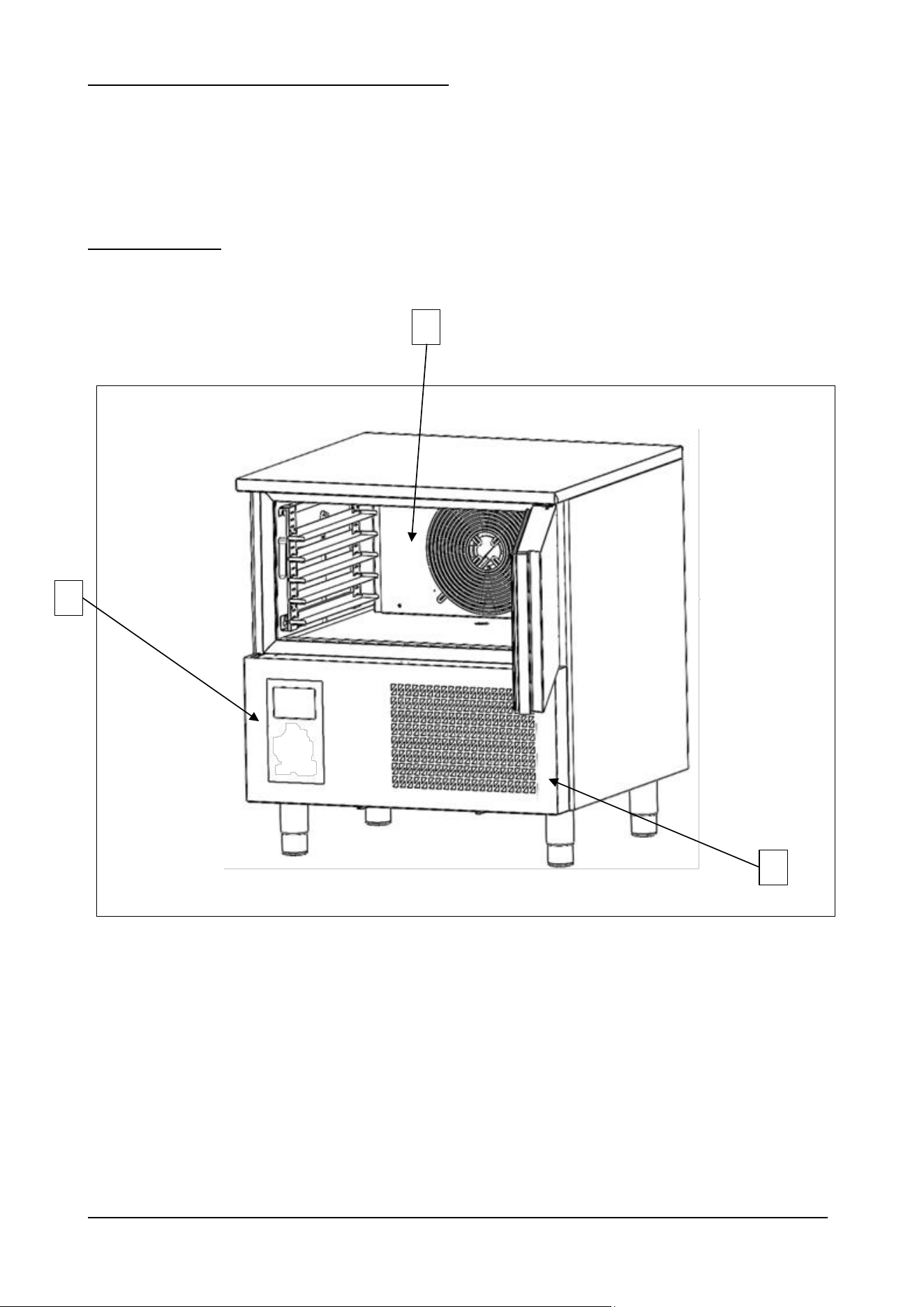
3.2.1 – MAIN PARTS
The appliance comprises the following parts:
− body;
− condenser unit (ref. 2, fig. 6);
− evaporator unit (ref. 1, fig. 6);
− control panel (ref. 3, fig. 6)
Fig. 6
1
3
2

BCB US Rev.00 09-2024 pag. 18
3.3 – NOISE
The appliance is designed and built to keep its noise level as low as possible.
3.4 –AMBIENT CONDITIONS
Installation site
Bakeries, confectioner’s, ice cream makers, and kitchens in general
Relative humidity
< 80% without condensation
Climatic class
5*
*The Climatic class 5 indicates that the appliance does work properly in an environment which remains below 104°F and 40% Hr
Tab. 2
BCB US Rev.00 09-2024 pag. 19
4 – TRANSPORT AND HANDLING
4.1 – TRANSPORT
The packing used is suitable for the type, dimensions and weight of the appliance and ensures that it is protected and
remains undamaged during transport and delivery to the purchaser.
The blast chiller must be placed in position and kept upright on a pallet and surrounded by its packing box throughout its
journey.
The blast chiller is handed over to the carrier ready to be handled.
The appliance must never be overturned.
The packing must be well placed on the platform of the means of transport and secured by
appropriate ropes.
Take the utmost care when lifting and positioning the blast chiller, so as to avoid serious damage
to persons or things. The manufacturer declines all responsibility if the indications for lifting
and transport the blast chiller are not observed.
Ambient temperature must never drop below 39°F during transport.
Once the blast chiller has been unpacked, the packing material must be eliminated and/or re-used in compliance with
current waste disposal regulations in the countries where the appliance will be used.
4.2. – HANDLING THE PACKED BLAST CHILLER
Take great care when lifting and handling the blast chiller; there is an injury hazard in handling
loads, which may also be fatal.
All handling and lifting operations must be carried out with great caution, making sure that all
personnel is strictly at a safety distance and that no-one stands under suspended loads, be they
still or in motion.
Before starting the operation, check the whole appliance handling area to identify any
dangerous points.
Ambient temperature must never drop below 39°F during transport.
BCB US Rev.00 09-2024 pag. 20
AUTHORIZED PERSONNEL
Specialised fork-lift truck operator.
Individual safety devices:
- safety shoes;
- safety gloves.
Personnel carrying out such operations must not wear rings, wrist watches, jewellery, loose or unfastened garments, such
as, for example, ties, torn garments, scarves, unbuttoned jackets or blouses with open zips, etc. In general, personnel
must wear safety apparel.
4.2.1 – WEIGHT AND DIMENSIONS
Model
BCB/05US
BCB/10US
BCB/15US
Dimensions
inches
33.9 X 32.4 X 37.8
33 7/8 X 33 7/8 X 61 3/8
33 7/8 X 33 7/8 X 74 7/8
Weight
lb
238
348
500
Tab.3
4.2.2 – MEANS REQUIRED
- To lift the appliance use a fork-lift truck of suitable minimum capacity.
The use of unsuitable equipment can cause accidents to those involved in the operation and/or
damage to the appliance.
The manufacturer declines all responsibility for improper non-compliant use of equipment for
lifting, transport and handling.
BCB US Rev.00 09-2024 pag. 21
5 – INSTALLATION
Use the utmost care in handling the appliance, so as to avoid damage to persons or things.
Servicing shall be performed only as recommended by the manufacturer
Do not start the appliance if there are faults on the control panel or parts are damaged.
Servicing shall be performed only as recommended by the manufacturer
Do not start the appliance if there are faults on the control panel or parts are damaged.
The appliance is to be installed in accordance with the Safety Standard for Refrigeration
Systems, ANSI/ASHRAE 15
WARNING:
Do not use means to accelerate the defrosting process or to clean, other than those
recommended by the manufacturer.
The appliance shall be stored in a room without continuously operating ignition sources
(for example: open flames, an operating gas appliance or an operating electric heater.
Do not pierce or burn.
Be aware that refrigerants may not contain an odour.
The minum distance between the walls and the appliance must be at least 30cm/0.4inch
Positioning near other equipment that reaches high temperatures is not recommended.
If it is necessary, provide a space of at least 50 cm/ 19.6 inch on the side and 70 cm/ 27.6 inch in the
back or erect an insulating wall.
AUTHORIZED PERSONNEL
Specialised electrician.
Individual safety devices:
− safety shoes;
− safety gloves.
Personnel carrying out such operations must not wear rings, wrist watches, jewellery, loose or unfastened garments, such
as, for example, ties, torn garments, scarves, unbuttoned jackets or blouses with open zips, etc. In general, personnel
must wear safety apparel.
5.1 – PREPARATION FOR INSTALLATION
BCB US Rev.00 09-2024 pag. 22
Work shall be undertaken under a controlled procedure so as to minimise the risk of a
flammable gas or vapour being present while the work is being performed.
The area shall be checked with an appropriate refrigerant detector prior to and during work, to ensure
the technician is aware of potentially toxic or flammable atmospheres
Ensure that the leak detection equipment being used is suitable for use with all applicable refrigerants,
i.e., nonsparking, adequately sealed, or intrinsically safe.
Under no circumstances shall potential sources of ignition be used in the searching for or
detection of refrigerant leaks. A halide torch (or any other detector using a naked flame)
shall not be used.
The area must provide good support, with a solid flat floor whose finish will ensure a suitable and safe
working place for personnel.
Ensure that the area is in the open or that it is adequately ventilated before breaking into the system
or conducting any hot work. A degree of ventilation shall continue during the period that the work is
carried out. The ventilation should safely disperse any released refrigerant and preferably expel it
externally into the atmosphere
If any hot work is to be conducted on the refrigerating equipment or any associated parts, appropriate
fire extinguishing equipment shall be available on hand. A dry chemical or CO2 fire extinguisher
should be adjacent to the charging area.
Positioning near other equipment that reaches high temperatures is not recommended.
Check that cabling will not be subject to wear, corrosion, excessive pressure, vibration,
sharp edges, or any other adverse environmental effects. The check shall also take into
account the effects of aging or continual vibration from sources such as compressors or
fans.
For installation prepare an area of manoeuvre suitable for:
− the dimensions of the appliance (see fig. 5),
− the chosen lifting equipment.
Choose an installation site:
− with all the connecting systems required for the appliance to work;
− with requisites that will allow the appliance to be used safely;
− with natural and/or artificial light suitable for the operations to be carried out (in compliance with specific
regulations).
5.2 – UNPACKING
Check that the packing has not been damaged during transport.
5.2.1 – MEANS REQUIRED
Use a fork-lift truck or equivalent equipment to lift the appliance.

BCB US Rev.00 09-2024 pag. 23
The use of unsuitable equipment can cause accidents to those involved in the operation and/or
damage to the appliance.
The manufacturer declines all responsibility for improper non-compliant use of equipment for
lifting, transport and handling.
BCB US Rev.00 09-2024 pag. 24
5.2.2 – UNPACKING PROCEDURE
All the handling and unpacking operations must be carried out with extreme care, making sure
that all personnel is strictly at a safety distance and that no-one stands under suspended loads,
be they still or in motion.
To unpack the appliance just remove its cardboard wrapping. Take the appliance off the pallet, lifting it by means of a
suitable fork-lift truck; the forks should be placed under the appliance taking care not to damage the two water tray
runners.
AFTER INSTALLING THE APPLIANCE, WAIT AT LEAST TWO HOURS BEFORE TURNING IT ON.
5.3 – HANDLING THE BLAST CHILLER
5.3.1 – MEANS REQUIRED
See paragraph 5.2.1.
The use of unsuitable equipment can cause accidents to those involved in the operation and/or
damage to the appliance.
The manufacturer declines all responsibility for improper non-compliant use of equipment for
lifting, transport and handling.
5.3.2 – HANDLING THE UNPACKED BLAST CHILLER
All the handling and unpacking operations must be carried out with extreme care, making sure that all
personnel is strictly at a safety distance and that no-one stands under suspended loads, be they still or in
motion.
All possible ignition sources, including cigarette smoking, should be kept sufficiently far away from the
site of installation, repairing, removing and disposal, during which refrigerant can possibly be released to
the surrounding space.
Prior to work taking place, the area around the equipment shall be surveyed to make sure that there are
no flammable hazards or ignition risks. “No Smoking” signs shall be displayed.
No person carrying out work in relation to a REFRIGERATING SYSTEM which involves exposing any
pipe work shall use any sources of ignition in such a manner that it may lead to the risk of fire or explosion.
To move blast chillers on wheels, release the brakes on the wheels and push, taking care to block the brakes again when
the appliance is in its permanent position.
To move blast chillers on feet, lift them with a suitable fork-lift truck; the forks should be placed under the appliance, taking
care not to damage the two water tray runners.
5.4 – BLAST CHILLER ASSEMBLY
The blast chiller is delivered to the customer assembled in all its parts.
Remove the water tray from the chamber and place it in position along the runners placed under the appliance between
the feet.

BCB US Rev.00 09-2024 pag. 25
5.5 – REMOVAL, EVACUATION and CHARGING PROCEDURES
WHEN BREAKING INTO THE REFRIGERANT CIRCUIT TO MAKE REPAIRS – OR FOR ANY
OTHER PURPOSE – CONVENTIONAL PROCEDURES SHALL BE USED. HOWEVER, FOR
FLAMMABLE REFRIGERANTS IT IS IMPORTANT THAT BEST PRACTICE BE FOLLOWED, SINCE
FLAMMABILITY IS A CONSIDERATION.
The following procedure shall be adhered to:
a) safely remove refrigerant following local and national regulations;
b) purge the circuit with inert gas;
c) evacuate (optional for A2L);
d) purge with inert gas (optional for A2L);
e) open the circuit by cutting or brazing.
The refrigerant charge shall be recovered into the correct recovery cylinders if venting is not allowed by local and
national codes. For appliances containing flammable refrigerants, the system shall be purged with oxygen-free nitrogen
to render the appliance safe for flammable refrigerants. This process might need to be repeated several times.
Compressed air or oxygen shall not be used for purging refrigerant systems.
For appliances containing flammable refrigerants, refrigerants purging shall be achieved by breaking the vacuum in the
system with oxygen-free nitrogen and continuing to fill until the working pressure is achieved, then venting to
atmosphere, and finally pulling down to a vacuum. This process shall be repeated until no refrigerant is within the
system. When the final oxygen-free nitrogen charge is used, the system shall be vented down to atmospheric pressure to
enable work to take place.
Ensure that the outlet for the vacuum pump is not close to any potential ignition sources
and that ventilation is available.
In addition to conventional charging procedures, the following requirements shall be followed.
a) Ensure that contamination of different refrigerants does not occur when using charging equipment. Hoses or lines
shall be as short as possible to minimise the amount of refrigerant contained in them.
b) Cylinders shall be kept in an appropriate position according to the instructions.
c) Ensure that the REFRIGERATING SYSTEM is earthed prior to charging the system with refrigerant.
d) Label the system when charging is complete (if not already).
e) Extreme care shall be taken not to overfill the REFRIGERATING SYSTEM.
Prior to recharging the system, it shall be pressure-tested with the appropriate purging gas. The system shall be leak-
tested on completion of charging but prior to commissioning. A follow up leak test shall be carried out prior to leaving the
site.
5.6 RECOVERY
When removing refrigerant from a system, either for servicing or decommissioning, it is recommended good practice that
all refrigerants are removed safely.
When transferring refrigerant into cylinders, ensure that only appropriate refrigerant recovery cylinders are employed.
Ensure that the correct number of cylinders for holding the total system charge is available. All cylinders to be used are
designated for the recovered refrigerant and labelled for that refrigerant (i.e., special cylinders for the recovery of
refrigerant). Cylinders shall be complete with pressure-relief valve and associated shut-off valves in good working order.
Empty recovery cylinders are evacuated and, if possible, cooled before recovery occurs.
The recovery equipment shall be in good working order with a set of instructions concerning the equipment that is at
hand and shall be suitable for the recovery of all appropriate refrigerants including, when applicable, FLAMMABLE
REFRIGERANTS. In addition, a set of calibrated weighing scales shall be available and in good working order. Hoses
shall be complete with leak-free disconnect couplings and in good condition. Before using the recovery machine, check
that it is in satisfactory working order, has been properly maintained and that any associated electrical components are
sealed to prevent ignition in the event of a refrigerant release. Consult manufacturer if in doubt.
The recovered refrigerant shall be returned to the refrigerant supplier in the correct recovery cylinder, and the relevant
waste transfer note arranged. Do not mix refrigerants in recovery units and especially not in cylinders.
If compressors or compressor oils are to be removed, ensure that they have been evacuated to an acceptable level to
make certain that FLAMMABLE REFRIGERANT does not remain within the lubricant. The evacuation process shall be
carried out prior to returning the compressor to the suppliers. Only electric heating to the compressor body shall be
employed to accelerate this process. When oil is drained from a system, it shall be carried out safely
BCB US Rev.00 09-2024 pag. 26
6 – SETTING UP
AFTER INSTALLING THE APPLIANCE, WAIT AT LEAST TWO HOURS BEFORE TURNING IT ON.
6.1 – CONNECTIONS
6.1.1 – ELECTRICAL CONNECTION
Electrical connection must be made by a specialised electrician.
− Check that the power supply voltage given on the ID plate corresponds to that available at the
installation site.
− Connections must be made to current regulations; the supply mains must have an efficient
earthing system compliant with electricity regulations in the country; this is a responsibility of
the customer.
− Do not make tight bends on the power lead and do not place any object whatsoever on top of
it.
The manufacture declines all responsibility for damage or accidents caused by failure to
observe such regulations.
ELECTRICAL CONNECTION PROCEDURE
The appliance is supplied by the manufacturer complete with power plug. Just connect the power plug to a socket at the
installation site; the system must be carried out to current regulations.
The electricity supply at the installation site must have the following requisites:
− Voltage: 1x115 Vac BCB/05US(R404A); 1x230 Vac BCB/05US(R449A); BCB/10US(R404A/R449A);
3x230 Vac (BCB15US)
− Frequency: 60 Hz
The connection to the power supply network must comply with the regulations in force in the country of the equipment
installation and must be carried out by a specialized electrician authorized by the Manufacturer.
Failure to comply with these rules may cause damage and injury, void the warranty and release the Manufacturer from all
liability.
Before proceeding with the electrical connection, always compare the system data with those shown on the
technical data plate.
When the appliance is in operation, the value of the supply voltage must not differ by +/-10% of the value shown
on the technical data plate.
Depending on the model, different electrical connections are required:
BCB/05US
BCB/10US
BCB/15US
The equipment is supplied by the
manufacturer complete with a power
cord and plug.
Connected the equipment to a power
outlet in the installation’s site
The equipment is supplied with a power cord and is NOT
supplied with a plug. A specialized electrician authorized
by the Manufacturer must connect an electrical cable
to own electrical panel
Supply voltage
1x115 Volt ~ 60 Hz
plug NEMA 5-20P / 5-15P
cable length 2.5 m [98.4” ]
1x220 Volt ~ 60 Hz
3x220 Volt ~ 60 Hz
Make sure that the cable:
- has no tight kinks;
- is not crushed by objects or other equipment;
- is not in contact with sharp or hot objects;
- does not hinder the passage of people.
BCB US Rev.00 09-2024 pag. 27
Upstream, the equipment must be provided with an easily accessible switch installed in the system according
to the regulations in force in the country of installation of the equipment. This switch must have an omnipolar contact
separation so as to guarantee complete disconnection under overvoltage category III.
A correct earth connection is mandatory and the earth cable must not be interrupted in any case by the protection switch.
When there are several appliances in the same room.
The effectiveness of the equipotential system must be properly checked according to what is stated in the current
legislation.
If it is necessary to disconnect the power plug, first make sure that the card is positioned to OFF on the display.
The manufacturer declines all responsibility for damage or accidents caused by failure to comply with these standards.
6.2 – PRELIMINARY CHECKS
The electrician fitter shall train the operator in the correct use of the blast chiller and give the basic notions of maintenance.
METHOD
The operations to prepare the blast chiller for initial start-up must be carried out by a specialised engineer, in the presence
of the operator, who can acquire information to carry out certain routine maintenance and cleaning.
Before starting up the appliance, a series of checks and inspections must be carried out for the purpose of preventing
errors or accidents during start-up.
− Check that the appliance has not been damaged during transport.
− Check with special care for any damage to the electrical box, push button control panel, wiring and pipes.
− Check that all external power sources have been connected properly.
− Check that the machine is perfectly level.
6.2.1 – REGULATION
Regulation carried out by unauthorized personnel may damage the appliance and expose the
operator to serious hazards. Regulation carried out by unauthorized personnel is considered
tampering with the appliance and as such null the warranty and relieve the manufacturer of any
responsibility.

BCB US Rev.00 09-2024 pag. 28
7 – USE
WARNING: Do not use electrical appliances inside the food/ice storage compartments unless
they are of the type recommended by the manufacturer
7.1 – USE FORSEEN
Blast chillers are appliances with a powerful refrigeration system that can rapidly reduce the temperature at the core of
food. Ideal for use in kitchens, bakeries and ice cream establishments.
The machine’s main work cycles are CHILLING and FREEZING. Each cycle includes two different end of cycle modes at
the point at which holding commences: temperature controlled (the probe inserted into the core of the product ends the
cycle when it reaches the set temperature) or time controlled (the cycle ends as soon as the set time expires).
- SOFT CHILLING. Positive “delicate” temperature reduction (+37°F). Food just out of the oven is quickly taken to
a temperature of 37°F in no longer than 90’, thus inhibiting bacterial proliferation and avoiding dehydration of the
cooked food due to evaporation. Food treated in this way can be preserved perfectly for 5-7 days without altering
its original qualities.
- HARD CHILLING. Positive “rapid” temperature reduction (+37°F). Also lasts for a maximum of 90’. This type
of process is used when the food to be chilled is thicker than an inch (i.e. large joints) and with dense or fatty
food. During this phase the appliance reaches -4°F air temperature and provides to accelerate penetration of
the cold into the food.
- FREEZING. Deep freezing or freezing (0°F). During this phase the appliance reaches -40°F air temperature.
This work cycle will take the core of the food to a temperature of 0°F in less than four hours (240’). The speed of
the process avoids the formation of macrocrystals, ensuring that when it is used the thawed food has its original
consistency, colour and quality.
- HOLDING. At the end of both the chilling and freezing cycles the machine will automatically go to the set holding
temperature.
7.2 – UNFORSEEN USE
Blast chillers cannot be used for purposes other than those described in point 7.1. In particular the appliance is not suitable
for storing food for an indefinite period.
BCB US Rev.00 09-2024 pag. 29
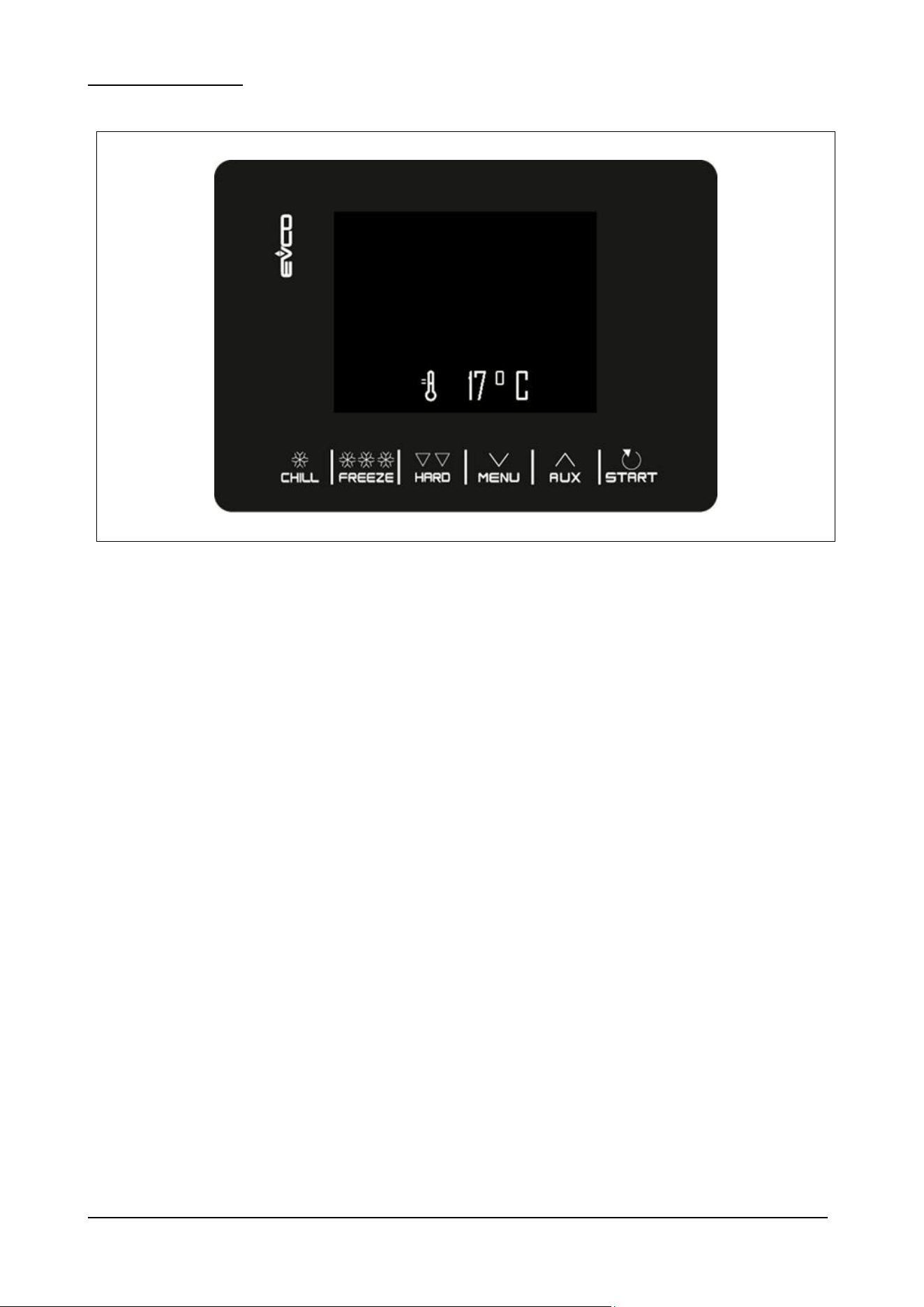
7.3 – CONTROL PANEL
Fig. 7
BCB US Rev.00 09-2024 pag. 30
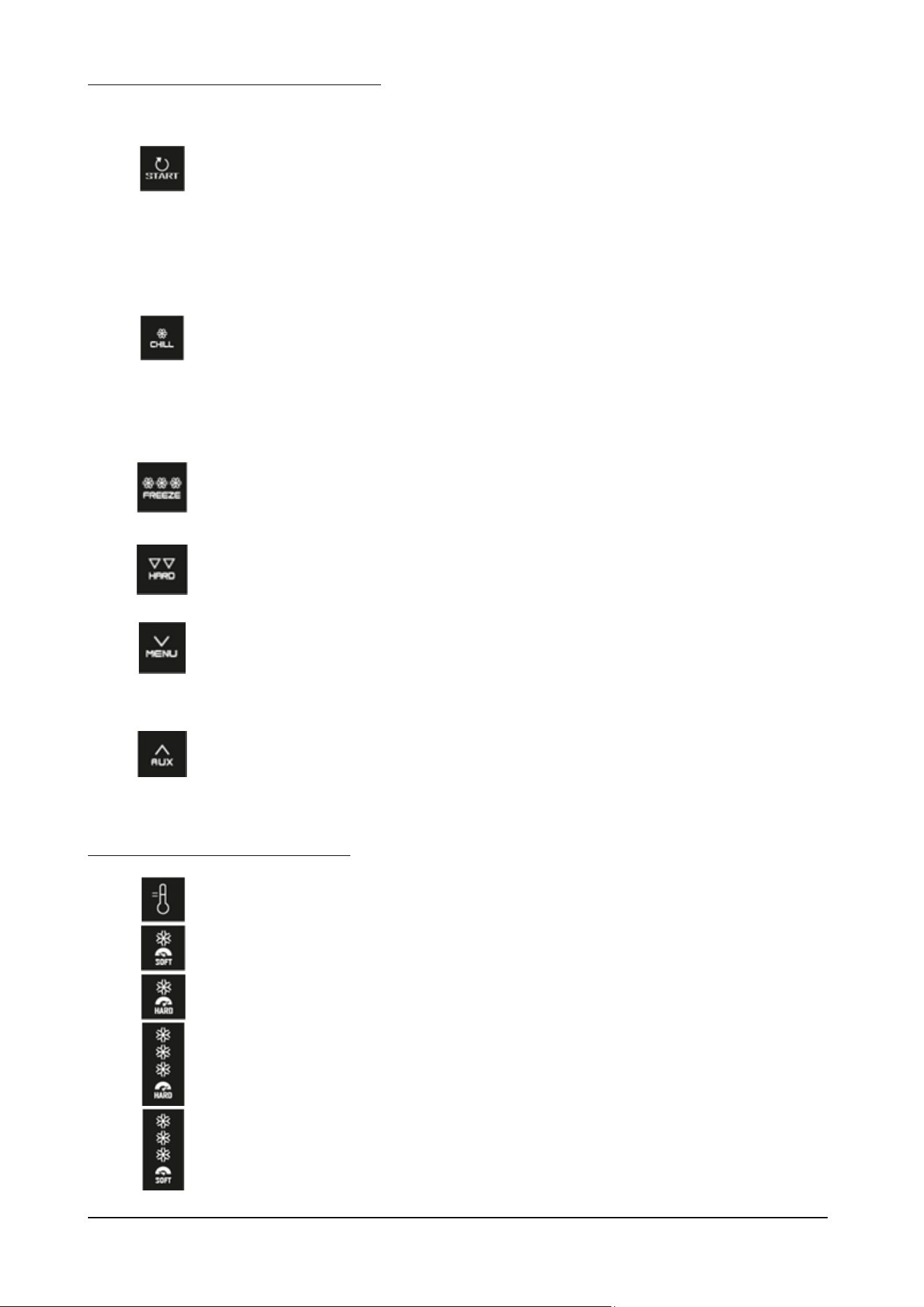
The buttons on the control panel are as follows:
START BUTTON
Short press: starts the selected function or gives access to the
selected menu page.
Long press for 2 seconds: interrupts the cycle in progress.
During a setting: allows you to make the value you want to change
editable, while a subsequent press of the same confirms the set
value.
CHILL BUTTON
Allows you to quickly select a blast chilling cycle.
Once a blast chilling cycle has been selected, it allows you to switch
from temperature-based blast chilling to time-based blast chilling and
vice versa.
During the quick selection of a blast chilling/freezing cycle: touching
the button 3 times consecutively takes the controller back to the
stand-by page.
Inside a menu or during a setting: acts as an "ESC" button and takes
the controller back to the upper page.
Warning: when a cycle is in progress, the button is not active; to
interrupt the cycle, press the "START" button for 2 seconds.
FREEZE BUTTON
Allows you to quickly select a freezing cycle.
Once you have selected a freezing cycle, it allows you to switch
from freezing by temperature to freezing by time and vice versa.
HARD BUTTON
Once the blast chilling/freezing cycle to be performed has been
selected, it allows you to switch from hard to soft mode and vice
versa.
MENU BUTTON
From the Home page: gives access to the machine settings menu.
Inside a menu: allows navigation downwards.
During a setting: decreases the value of the quantity you want to
change.
AUX BUTTON
From the Home page: gives access to the machine's special cycle
selection menu.
Inside a menu: allows navigation upwards.
During a setting: increases the value of the quantity you wish to
modify.
The icons on the control panel display are:
CABINET TEMPERATURE
ICON
CHILLING CYCLE ICON
ON when a chilling cycle is selected
HARD CHILLING CYCLE
ICON
ON when a hard chilling cycle is selected
FREEZING CYCLE
ON when a freezing cycle is selected
SOFT FREEZING CYCLE
ICON
ON when a soft freezing cicle is selected
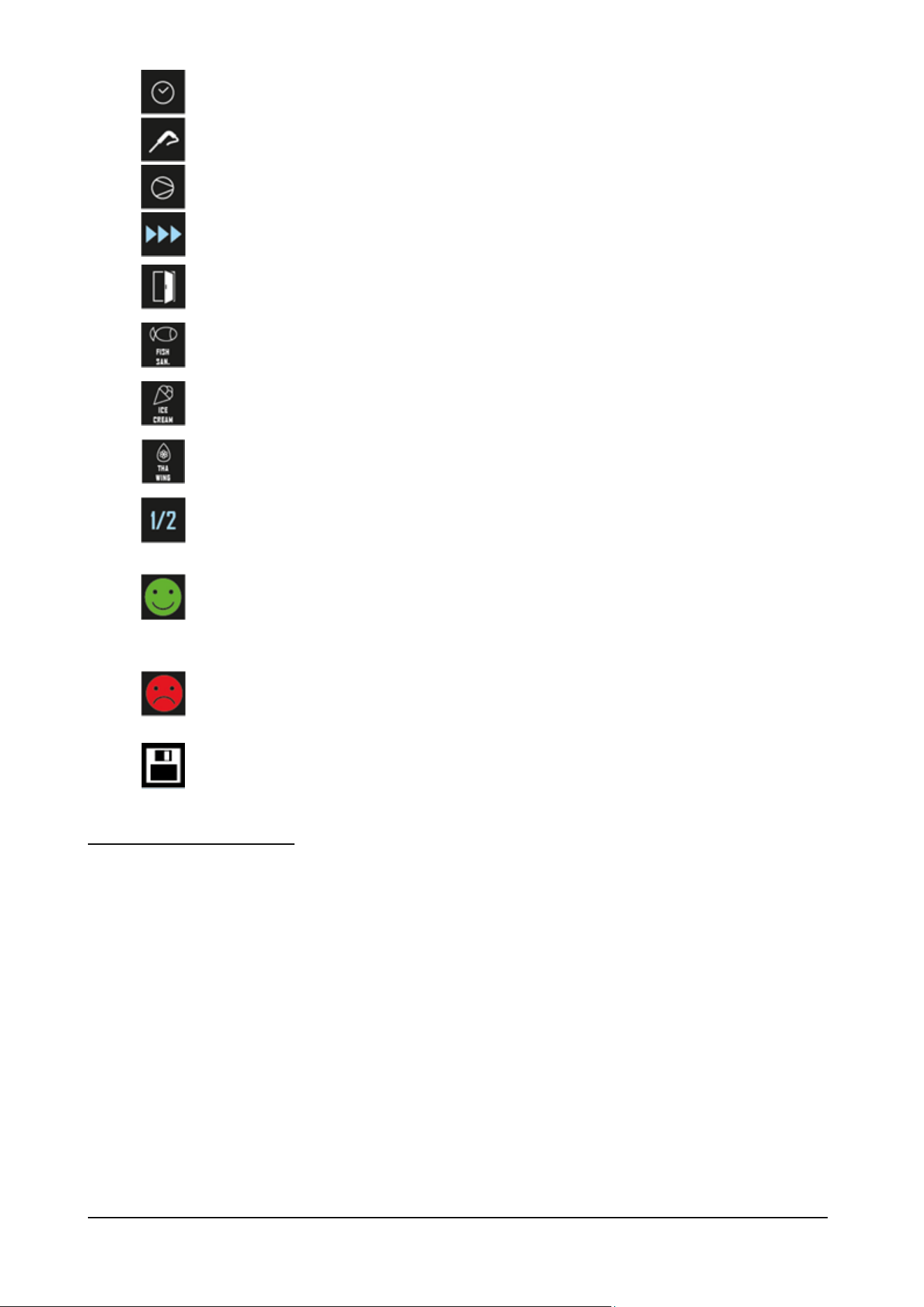
BCB US Rev.00 09-2024 pag. 31
CYCLE BY TIME ICON
ON when the cycle by time is selected
CYCLE BY TEMPERATURE
ICON
On when the cycle by temperature is selected
COMPRESSOR ICON
ON when the compressor is running
CYCLE IN PROGRESS
ICON
ON when a cicle cycle is in progress
DOOR OPEN ICON
ON when the door is open. The display will automatically
disappear the next time the door is closed or a button is
pressed
FISH SANIFICATION ICON
ON when a fish sanification cycle is in progress
ICE CREAM ICON
ON when a ice cream cycle is in progress
THAWING ICON
ON when a fish thawing cycle is in progress
NUMER OF PHASES
Indicate the the running phase of the cycle
BLAST CHILLING /
FREEZING CYCLE
SUCCESSFULLY
COMPLETED
ON when a cycle has completed successfully
BLAST CHILLING /
FREEZING CYCLE NOT
COMPLETED
SUCCESSFULLY
ON when a cycle has not completed successfully
CUSTOM RECIPE
STORAGE
7.4 – CONTROL PROCEDURES
The entire device is controlled by an electronic board.
Connect the power supply to the device: a neutral system loading screen will be displayed.
Once loading is complete, the device will return to the state it was in before being disconnected, i.e.:
- on the Home screen without any power failure message;
- in cycle execution, with POWER FAILURE message indicating the power failure.
If a power failure occurs when no function is in progress, when the power is restored the device will return to the state it
was in before the power failure.
If a power failure occurs when a function is active, when the power is restored the device will behave as follows:
- with a blast chilling or freezing in progress, the cycle is resumed taking into account the duration of the power failure
- with a conservation in progress, the cycle continues maintaining the same settings.
If the power failure was long enough to cause the clock error (code “RTC”), it will be necessary to set the day and real time
again.
To silence the buzzer, simply press any key.

BCB US Rev.00 09-2024 pag. 32
7.5 – USE PROCEDURES
Clean the inside of the chamber before using the machine.
After installation or a prolonged idle period, it is good practice to operate the empty appliance until it reaches the set
temperature. To achieve good output from the blast chiller it is advisable to place the food inside in such a way as to assist
air circulation: do not obstruct the fan, do not stack trays on top of each other, distribute the load neatly and do not cove r
the containers with lids or cling film.
In order to avoid altering the food, it is also advisable not to overload the machine beyond the permitted load, not to use
pieces thicker than 2-3” and to limit door opening as much as possible.
Clean and sterilise the core probe before use. The probe must be placed in the centre of the largest joint or piece, taking
care that the point does not go right through the food to come into contact with the tray.
To improve the efficacy of the working cycle is recommended to perform a pre-cooling of the cell, by turning on
the machine at least 15 min before insert the product, both in killing and freezing.
When a temperature controlled cycle is selected the electronic circuit board checks the temperature read by the
chamber probe and core probe to assess correct insertion of the probe (AUTOMATIC probe identification). This
check lasts just over two minutes, at the end of which the cycle proceeds normally if the probe is properly inserted.
This check lasts just over 2 minutes, accordingly with established parameters, at the end of which the cycle
proceeds with a temperature controlled cycle if the probe is properly inserted. In this case the temperature of the
probe will be showed and the icon will remain turned on.
If the test has a negative result, after a minute of buzzer’s alarm, the display will show the icon and the cycle
will proceed with a time controlled cycle.

BCB US Rev.00 09-2024 pag. 33
7.6 – CHILLING and FREEZING CYCLE
Load the machine suitably with the food to be chilled, place the core probe into the food and close the door.
With the appliance on STANDBY press the or buttons to select a blast chilling cycle or a freezing cycle
respectively.
The device will propose a cycle by time .
To switch from this mode to cycle by probe , press the button the or again.
The selected cycle will propose either the preloaded settings for that cycle.
By pressing , it will be possible to quickly modify, within the permitted ranges, the value of a single piece of
data.
Once the modification is complete, press to run the cycle button .
If the cycle is by probe, the test is performed to verify the correct insertion of the needle probe into the food to be chilled.
If the test is not passed, the cycle automatically switches to timed mode: the buzzer emits a sound and the type of cycle
control is converted from temperature to time on the display.

BCB US Rev.00 09-2024 pag. 34
7.7 – HARD CHILLING and SOFT FREEZING CYCLE
Load the machine suitably with the food to be chilled, place the core probe into the food and close the door.
With the appliance on STANDBY press the or buttons to select a blast chilling cycle or a freezing cycle
respectively.
The device will propose a cycle by time .
To switch from this mode to cycle by probe , press the button the or again.
Once the desired cycle has been selected, by pressing the button it is possible to add a phase (hard for chilling, soft
for freezing) which will be carried out before the standard phase, thus switching from one-phase cycles to two-phase cycles.
The selected cycle will propose either the preloaded settings for that cycle.
By pressing , it will be possible to quickly modify, within the permitted ranges, the value of a single piece of
data.
Once the modification is complete, press to run the cycle button .
If the cycle is by probe, the test is performed to verify the correct insertion of the needle probe into the food to be chilled.
If the test is not passed, the cycle automatically switches to timed mode: the buzzer emits a sound and the type of cycle
control is converted from temperature to time on the display.
BCB US Rev.00 09-2024 pag. 35
7.8 – SPECIAL USES
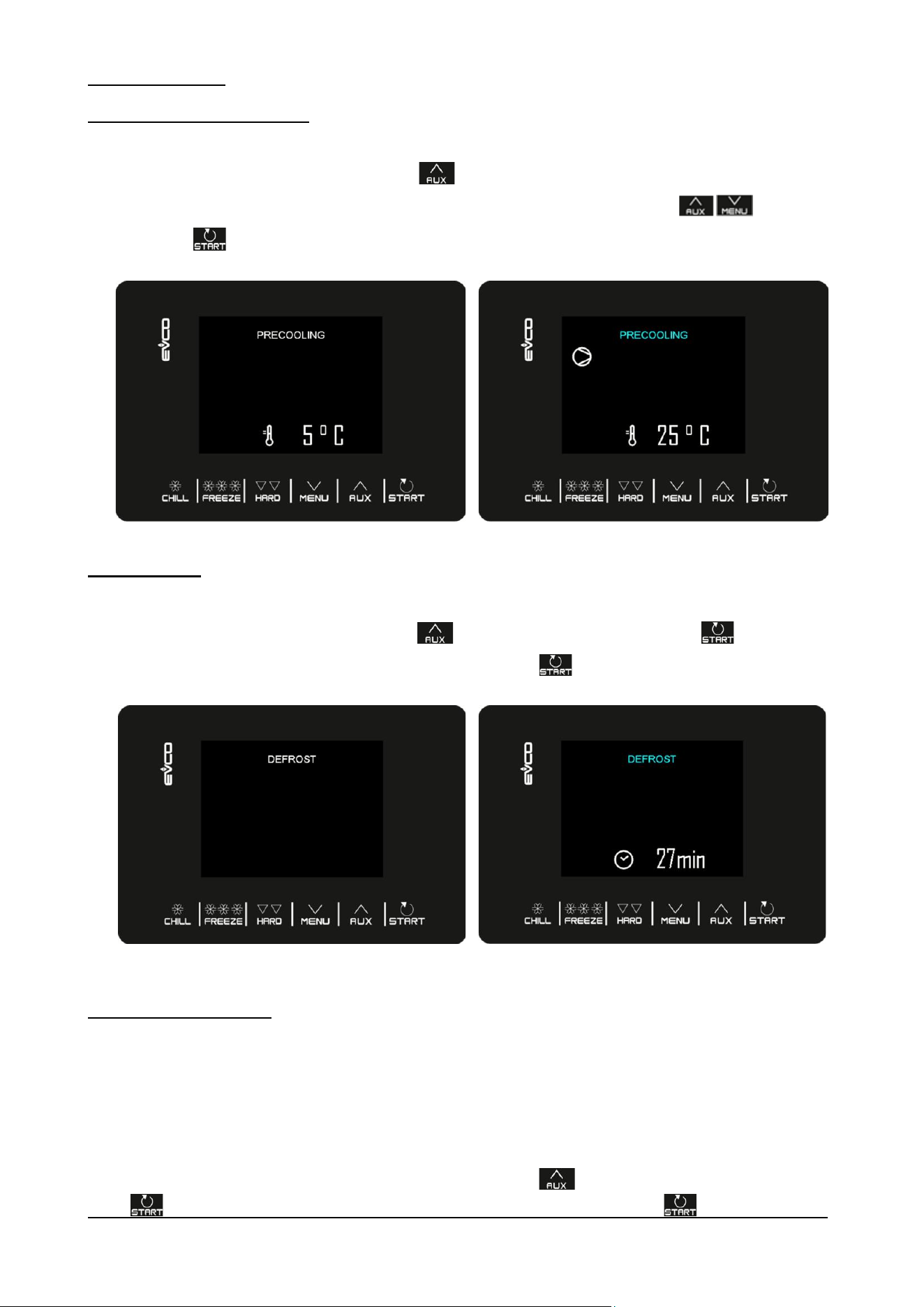
7.8.1 – PRE-COOLING FUNCTION
If the temperature of the food to be chilled is very high (above 149°F) it is advisable to pre-chill it in the following way:
Access the SPECIAL CYCLES menu from the button and select PRECOOLING.
At this point the work SETPOINT setting screen appears, and it can be changed using the keys
Press the button and cycle will start.
7.8.2 – DEFROST
The defrost can be activated when the machine is on STANDBY and the evaporator temperature does not exceed 46°F,
Access the SPECIAL CYCLES menu from the button and select DEFROST, press the button : at this point the
word DEFROST will be displayed and the next time you press the button the cycle will start.
Defrosting is also performed automatically during the storage or pre-cooling phases.
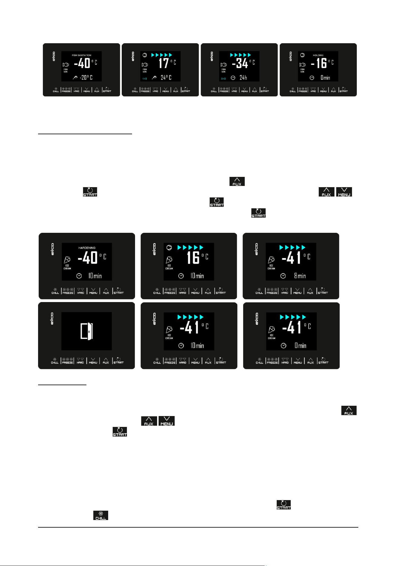
7.8.3 – FISH SANITIZATION
The fish sanitization cycle is only available if the needle probe is present.
This is a special cycle consisting of the following phases:
1. blast chilling by probe with cell setpoint equal to -36°F and with product temperature setpoint equal to -4°F;
2. maintenance by time of duration equal to 24 hours and cell setpoint equal to -4°F;
The needle probe insertion test is always performed at the beginning of the cycle: if the test is not completed, the buzzer
sounds and the cycle is interrupted.
To start this cycle access the SPECIAL CYCLES menu from the button and select FISH SANITATION, press the
button : at this point the start screen is displayed and the next time you press the button the cycle will start.
BCB US Rev.00 09-2024 pag. 36
During the execution of a sanitization, the device will always display the cell temperature and, depending on the phase in
progress, the end blast chilling temperature or the duration of the maintenance.
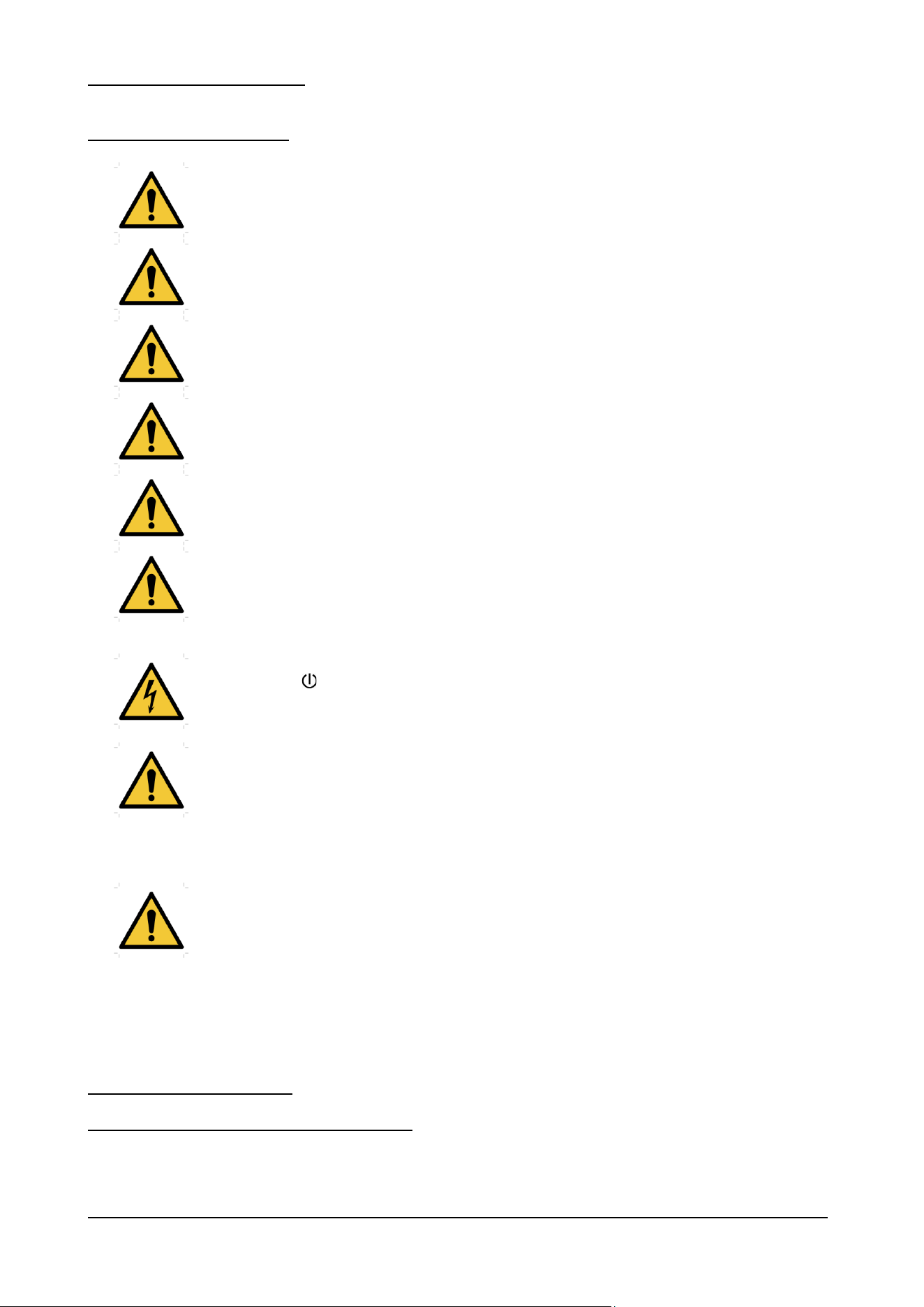
7.8.4 – ICE CREAM HARDENING
This type of cycle is mainly used in the ice cream and pastry sectors to give a “thermal shock” to the products being
processed.
It is a continuous freezing cycle, in which each time the door is opened, the decrease in the time set with 10 minutes will
restart regardless of the value of the setpoint -40°F.
To start this cycle access the SPECIAL CYCLES menu from the button and select ICE CREAM HARDENING ,
press the button : at this point the start screen will be displayed from which you can use the buttons to
change the timer time. When you press the next time the button , the cycle will start and the timer will expire and the
buzzer will sound. The cycle will continue in any case until you press the button for 2 seconds.
7.8.5 – RECIPES
There are 7 pre-set programs ready to use that offer a series of cycles optimized for the type of food.
These 7 recipes can be modified before the start of the cycle, but cannot be saved or overwritten.
To view the list of available blast chilling/freezing programs, access the SPECIAL CYCLES menu from the button
and select RECIPES. Use the buttons to select the desired recipe, change the setpoint if necessary and
start by pressing the button .
In addition to the 7 standard recipes (not modifiable), the controller provides 20 additional programs (from P1 to P20) that
can be used by the user to save the settings of their own recipe.
These 20 programs are listed after the 7 preset recipes and identified with the label “- - -” to indicate that the position is
empty.
When the user saves the settings of a recipe, the label “Px” will automatically appear based on the position in which it is
saved.
To save or overwrite one of the 20 recipes, proceed as follows:
1. Place the cursor in the position where you want to save the recipe, press the button ;
2. Use the button to change the mode from chilling cycle by time to chilling cycle by temperature and vice versa

BCB US Rev.00 09-2024 pag. 37
or use the button to change the mode from freezing cycle by time to freezing cycle by temperature and vice
versa;
3. Use the button to change the mode from SOFT to HARD and vice versa;
4. Use the button to enter the cycle value editing and scrolling mode;
5. Use the button to enter the selected value, modify it with the buttons and confirm by pressing
again or exit without modifying by pressing the button ;
6. When you return to the main screen to start the cycle, the icon appears on the display as a reminder to save the
recipe; press the button to save it;
7. Press the button to start the cycle.
BCB US Rev.00 09-2024 pag. 38
8 – MAINTENANCE AND REPAIR
8.1 – SPECIAL PRECAUTIONS
Servicing shall be performed only as recommended by the manufacturer
Contact the manufacturer for any anomalies not described in this manual; contact the manufacturer
also for any doubts during the maintenance operations described herein.
WARNING
Do not use means to accelerate the defrosting process or to clean, other than those recommended
by the manufacturer.
The appliance shall be stored in a room without continuously operating ignition sources (for
example: open flames, an operating gas appliance or an operating electric heater).
Do not pierce or burn.
Be aware that refrigerants may not contain an odour.
Maintenance carried out by unauthorized personnel may damage the appliance and expose the
operator to serious hazards. Maintenance carried out by unauthorized personnel is considered
tampering with the appliance and therefore nulls the warranty and relieves the manufacturer of any
responsibility.
Any routine or extraordinary maintenance operation that requires the electric box to be opened or
the machine to be dismantled, even partially, must be carried out only after the appliance has been
switched off, on the display, and unplugged.
Any maintenance operations carried out on a live machine may cause people serious accidents
which may also be fatal.
The safety devices must be deactivated only by authorized personnel, who will guarantee safety for
people and avoid damage to the machine. The safety devices must be carefully activated again after
carrying out maintenance.
During maintenance or repairs unauthorized persons must keep a safe distance from the appliance.
Observe the intervals prescribed or indicated in this manual for making inspections.
At the end of maintenance or repairs the appliance can be started only after the specialist engineer
has made sure that:
- all the work has been fully carried out;
- the safety systems are active;
- the appliance is working perfectly;
- no-one is working on the appliance.
8.2 – ROUTINE MAINTENANCE
8.2.1 – ROUTINE MAINTENANCE TABLE (TAB. 5)
Prior to beginning work on systems containing flammable refrigerants, safety checks are necessary to ensure that the
risk of ignition is minimised. For repair to the REFRIGERATING SYSTEM, Clauses ‘Work procedure’ to ‘No ignition
sources’ shall be completed prior to conducting work on the system.
BCB US Rev.00 09-2024 pag. 39
Work Procedure:
Work shall be undertaken under a controlled procedure so as to minimise the risk of a
flammable gas or vapour being present while the work is being performed.
The area shall be checked with an appropriate refrigerant detector prior to and during
work, to ensure the technician is aware of potentially toxic or flammable atmospheres.
Ensure that the leak detection equipment being used is suitable for use with all applicable
refrigerants, i.e., nonsparking, adequately sealed, or intrinsically safe.
If any hot work is to be conducted on the refrigerating equipment or any associated parts,
appropriate fire extinguishing equipment shall be available on hand. A dry chemical or CO2
fire extinguisher should be adjacent to the charging area.
No Ignition Sources:
No person carrying out work in relation to a REFRIGERATING SYSTEM which involves
exposing any pipe work shall use any sources of ignition in such a manner that it may lead
to the risk of fire or explosion. All possible ignition sources, including cigarette smoking,
should be kept sufficiently far away from the site of installation, repairing, removing and
disposal, during which refrigerant can possibly be released to the surrounding space. Prior
to work taking place, the area around the equipment shall be surveyed to make sure that
there are no flammable hazards or ignition risks. “No Smoking” signs shall be displayed.
Ensure that the area is in the open or that it is adequately ventilated before breaking into
the system or conducting any hot work. A degree of ventilation shall continue during the
period that the work is carried out. The ventilation should safely disperse any released
refrigerant and preferably expel it externally into the atmosphere.
Component
Type of operation
Timing
Responsibility
Method
Chamber
Cleaning
When needed
Appliance operator
See para. 8.2.2
External part
Cleaning
When needed
Appliance operator
See para. 8.2.3
Condenser
Cleaning
Every 30 days
Appliance operator
See para. 8.2.4
Core probe
Cleaning
Every cycle
Appliance operator
See para. 8.2.5
Tab. 5
8.2.2 –CLEANING THE CHAMBER
Carry out this operation whenever necessary.
APPLIANCE STATUS:
- I/O main switch in position “O” (OFF);
- power supply plug disconnected from the mains.
AUTHORIZED PERSONNEL
Appliance operator.
BCB US Rev.00 09-2024 pag. 40
METHOD
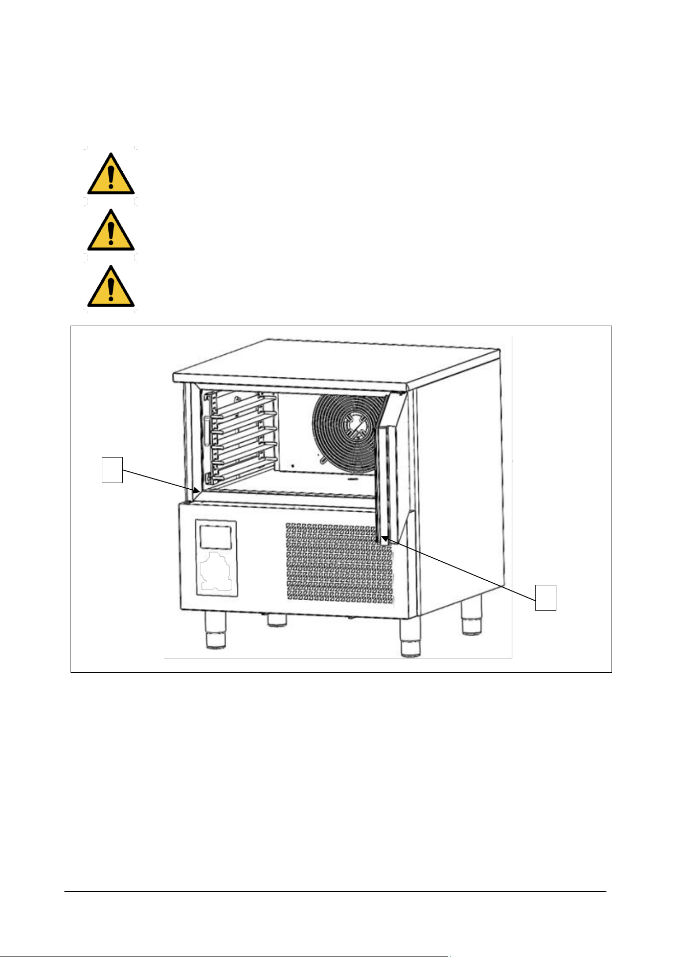
Clean very carefully the internal part of the chamber, the door closure surface (ref. 1 fig. 8) and gasket (ref. 2 fig. 8), using
a non-abrasive sponge soaked in neutral detergent. Rinse with a sponge soaked in water and dry with a clean cloth.
Proper cleaning of the inside of the appliance prevents the formation of bad odour which could affect the end product
negatively.
Use exclusively water and non-abrasive neutral detergent for cleaning. The use of different products
could damage the surface of the appliance and compromise the quality and healthiness of the
product being processed.
Do not use abrasive sponges.
When cleaning do not use cloths that leave lint.
Do not use water jets to clean the appliance.
Fig. 8
2
1
BCB US Rev.00 09-2024 pag. 41
8.2.3 – CLEANING THE OUTSIDE OF THE APPLIANCE
Carry out this operation whenever necessary.
APPLIANCE STATUS:
- I/O main switch in position “O” (OFF);
- power supply plug disconnected from the mains.
AUTHORIZED PERSONNEL
Appliance operator.
METHOD
Clean the outer surface of the appliance (steel base and panelling), using a non-abrasive sponge soaked in neutral
detergent. Rinse with a sponge soaked in water and dry with a clean cloth.
Use exclusively water and non-abrasive neutral detergent for cleaning. The use of different products
could damage the surface of the appliance and compromise the quality and healthiness of the
product being processed.
Do not use abrasive sponges.
When cleaning do not use cloths that leave lint.
BCB US Rev.00 09-2024 pag. 42
8.2.4 – CLEANING THE CONDENSER
Carry out this operation every 30 days.
APPLIANCE STATUS:
- I/O main switch in position “O” (OFF);
- power supply plug disconnected from the mains.
AUTHORIZED PERSONNEL
Appliance operator.
METHOD
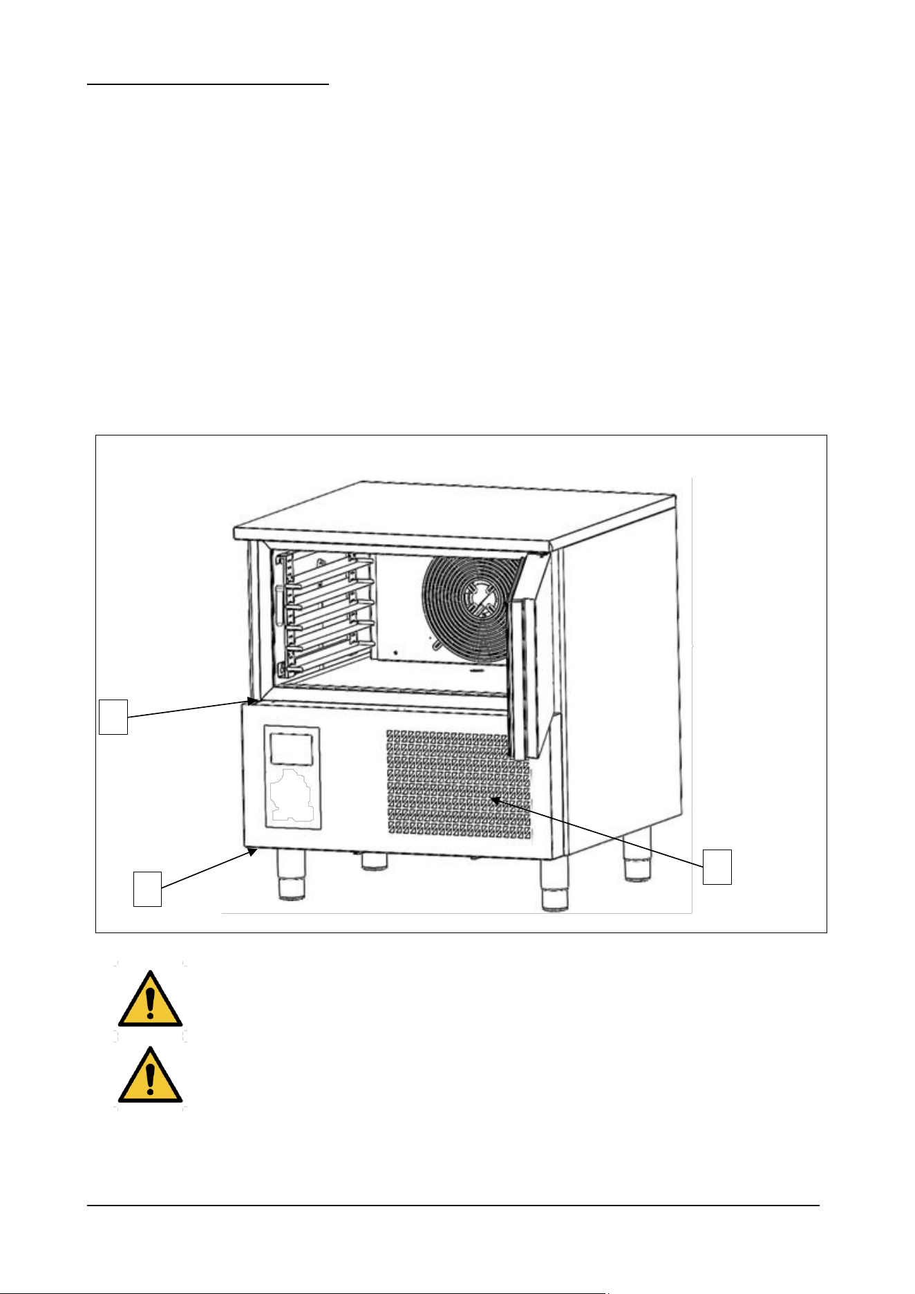
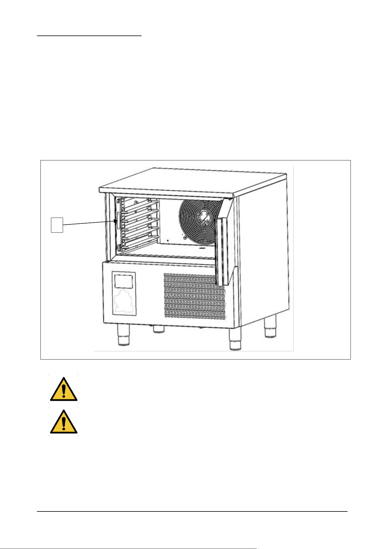
To ensure that the appliance works properly and efficiently, the air condenser (ref. 1 fig. 9) must be kept clean so that the
air can circulate freely. This operation should be carried out every 30 days. Remove the control panel by loosening the
screws (ref. 2 and 3 fig. 9). Clean with a non-metal brush to remove all the dust and fluff from the fins. It is advisable to
use a vacuum cleaner so that dust does not float in the air. If there are greasy deposits, eliminate with a brush soaked in
alcohol. DO NOT SCRAPE THE SURFACES WITH POINTED OR ABRASIVE OBJECTS.
Fig. 9
The condenser has sharp edges. When carrying out the operations mentioned above, wear safety
gloves, goggles and face masks.
Do not use direct water jets to clean the appliance.
2
3
1
BCB US Rev.00 09-2024 pag. 43
8.2.5 – CLEANING THE CORE PROBE
Carry out this operation at every cycle.
APPLIANCE STATUS:
- I/O main switch in position “O” (OFF);
AUTHORIZED PERSONNEL
Appliance operator.
METHOD
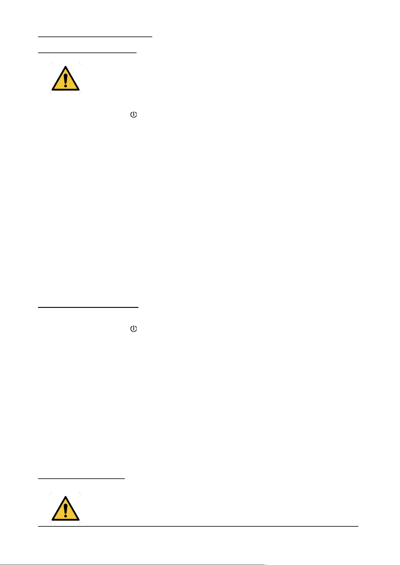
The core probe (ref. 1 fig. 10) must always be cleaned before a new cycle so as to avoid polluting the product in any way.
Remove all residue by means of a sponge soaked in neutral detergent. Rinse with lots of water and apply a sterilising
product.
Fig. 10
Do not pull the probe wire; you may damage it.
The probe has a very pointed end. During cleaning always wear safety gloves and take the utmost
care.
1
BCB US Rev.00 09-2024 pag. 44
8.3 – EXTRAORDINARY MAINTENANCE
8.3.1- REFRIGERANT EQUIPMENT
Where electrical components are being changed, they shall be fit for the purpose and to the
correct specification. At all times, the manufacturer’s maintenance and service guidelines
shall be followed. If in doubt, consult the manufacturer’s technical department for
assistance..
APPLIANCE STATUS:
- ON/OFF button on OFF ( on the display);
- power supply plug disconnected from the mains.
AUTHORIZED PERSONNEL
Specialized electrician.
METHOD
The following checks shall be applied to installations using FLAMMABLE REFRIGERANTS:
a) the actual REFRIGERANT CHARGE is in accordance with the room size within which the refrigerant containing
parts are installed;
b) the ventilation machinery and outlets are operating adequately and are not obstructed;
c) if an indirect refrigerating circuit is being used, the secondary circuit shall be checked for the presence of
refrigerant;
d) marking to the equipment continues to be visible and legible. Markings and signs that are illegible shall be
corrected;
e) refrigerating pipe or components are installed in a position where they are unlikely to be exposed to any
substance which may corrode refrigerant containing components, unless the components are constructed of
materials which are inherently resistant to being corroded or are suitably protected against being so corroded.
8.3.2- ELECTRICAL COMPONENTS
APPLIANCE STATUS:
- ON/OFF button on OFF ( on the display);
- power supply plug disconnected from the mains.
AUTHORIZED PERSONNEL
Specialized electrician.
METHOD
Repair and maintenance to electrical components shall include initial safety checks and component inspection
procedures. If a fault exists that could compromise safety, then no electrical supply shall be connected to the circuit until
it is satisfactorily dealt with. If the fault cannot be corrected immediately but it is necessary to continue operation, an
adequate temporary solution shall be used. This shall be reported to the owner of the equipment, so all parties are
advised.
Initial safety checks shall include:
a) that capacitors are discharged: this shall be done in a safe manner to avoid possibility of sparking;
b) that no live electrical components and wiring are exposed while charging, recovering or purging the system;
c) that there is continuity of earth bonding
8.3.3- SEALED COMPONENTS
During repairs to sealed components, all electrical supplies shall be disconnected from the
equipment being worked upon prior to any removal of sealed covers, etc. If it is absolutely
necessary to have an electrical supply to equipment during servicing, then a permanently
operating form of leak detection shall be located at the most critical point to warn of a
potentially hazardous situation.
BCB US Rev.00 09-2024 pag. 45
APPLIANCE STATUS:
- ON/OFF button on OFF ( on the display);
- power supply plug disconnected from the mains.
AUTHORIZED PERSONNEL
Specialized electrician.
METHOD
Particular attention shall be paid to the following to ensure that by working on electrical components, the casing is not
altered in such a way that the level of protection is affected. This shall include damage to cables, excessive number of
connections, terminals not made to original specification, damage to seals, incorrect fitting of glands, etc.
Ensure that the apparatus is mounted securely.
Ensure that seals or sealing materials have not degraded to the point that they no longer serve the purpose of preventing
the ingress of flammable atmospheres. Replacement parts shall be in accordance with the manufacturer’s specifications.
8.3.4- INTRINSICALLY SAFE COMPONENTS
Do not apply any permanent inductive or capacitance loads to the circuit without ensuring
that this will not exceed the permissible voltage and current permitted for the equipment in
use.
APPLIANCE STATUS:
- ON/OFF button on OFF ( on the display);
- power supply plug disconnected from the mains.
AUTHORIZED PERSONNEL
Specialized electrician.
METHOD
Intrinsically safe components are the only types that can be worked on while live in the presence of a flammable
atmosphere. The test apparatus shall be at the correct rating.
Replace components only with parts specified by the manufacturer. Other parts can result in the ignition of refrigerant in
the atmosphere from a leak.
NOTE: The use of silicon sealant can inhibit the effectiveness of some types of leak detection equipment. Intrinsically safe components
do not have to be isolated prior to working on them.
8.3.5- CABLING
APPLIANCE STATUS:
- ON/OFF button on OFF ( on the display);
- power supply plug disconnected from the mains.
AUTHORIZED PERSONNEL
Specialized electrician.
METHOD
Check that cabling will not be subject to wear, corrosion, excessive pressure, vibration, sharp edges, or any other
adverse environmental effects. The check shall also take into account the effects of aging or continual vibration from
sources such as compressors or fans.

BCB US Rev.00 09-2024 pag. 46
8.3.6- DETECTION OF FLAMMABLE REFRIGERANTS
Under no circumstances shall potential sources of ignition be used in the searching for or
detection of refrigerant leaks. A halide torch (or any other detector using a naked flame) shall
not be used.
APPLIANCE STATUS:
- ON/OFF button on OFF ( on the display);
- power supply plug disconnected from the mains.
AUTHORIZED PERSONNEL
Specialized electrician.
METHOD
The following leak detection methods are deemed acceptable for all refrigerant systems.
Electronic leak detectors may be used to detect refrigerant leaks but, in the case of FLAMMABLE REFRIGERANTS, the
sensitivity might not be adequate, or might need recalibration. (Detection equipment shall be calibrated in a refrigerant-
free area.) Ensure that the detector is not a potential source of ignition and is suitable for the refrigerant used.
Leak detection equipment shall be set at a percentage of the LFL of the refrigerant and shall be calibrated to the
refrigerant employed, and the appropriate percentage of gas (25 % maximum) is confirmed.
Leak detection fluids are also suitable for use with most refrigerants but the use of detergents containing chlorine shall be
avoided as the chlorine can react with the refrigerant and corrode the copper pipe-work.
NOTE Examples of leak detection fluids are
– bubble method,
– fluorescent method agents.
If a leak is suspected, all naked flames shall be removed/extinguished.
If a leakage of refrigerant is found which requires brazing, all of the refrigerant shall be recovered from the system, or
isolated (by means of shut off valves) in a part of the system remote from the leak. Removal of refrigerant shall be
according to 8.3.7 “REMOVAL AND EVACUATION”.
8.3.7- REMOVAL AND EVACUATION
APPLIANCE STATUS:
- ON/OFF button on OFF ( on the display);
- power supply plug disconnected from the mains.
AUTHORIZED PERSONNEL
Specialized electrician.
METHOD
When breaking into the refrigerant circuit to make repairs – or for any other purpose – conventional procedures shall be
used. However, for flammable refrigerants it is important that best practice be followed, since flammability is a
consideration. The following procedure shall be adhered to:
a) safely remove refrigerant following local and national regulations;
b) purge the circuit with inert gas;
c) evacuate;
d) purge with inert gas;
e) open the circuit by cutting or brazing.
The refrigerant charge shall be recovered into the correct recovery cylinders if venting is not allowed by local and
national codes. For appliances containing flammable refrigerants, the system shall be purged with oxygen-free nitrogen
to render the appliance safe for flammable refrigerants. This process might need to be repeated several times.
Compressed air or oxygen shall not be used for purging refrigerant systems.
For appliances containing flammable refrigerants, refrigerants purging shall be achieved by breaking the vacuum in the
system with oxygen-free nitrogen and continuing to fill until the working pressure is achieved, then venting to

BCB US Rev.00 09-2024 pag. 47
atmosphere, and finally pulling down to a vacuum (optional for A2L). This process shall be repeated until no refrigerant is
within the system (optional for A2L). When the final oxygen-free nitrogen charge is used, the system shall be vented
down to atmospheric pressure to enable work to take place.
Ensure that the outlet for the vacuum pump is not close to any potential ignition sources and that ventilation is available.
8.3.8- CHARGING PROCEDURES
APPLIANCE STATUS:
- ON/OFF button on OFF ( on the display);
- power supply plug disconnected from the mains.
AUTHORIZED PERSONNEL
Specialized electrician.
METHOD
In addition to conventional charging procedures, the following requirements shall be followed:
a) Ensure that contamination of different refrigerants does not occur when using charging equipment. Hoses or
lines shall be as short as possible to minimise the amount of refrigerant contained in them.
b) Cylinders shall be kept in an appropriate position according to the instructions.
c) Ensure that the REFRIGERATING SYSTEM is earthed prior to charging the system with refrigerant.
d) Label the system when charging is complete (if not already).
e) Extreme care shall be taken not to overfill the REFRIGERATING SYSTEM.
Prior to recharging the system, it shall be pressure-tested with the appropriate purging gas. The system shall be leak-
tested on completion of charging but prior to commissioning. A follow up leak test shall be carried out prior to leaving the
site.
If the appliance needs extraordinary maintenance, or if operating anomalies occur that are not described in this manual,
contact the manufacturer.
8.3.9- RECOVERY
APPLIANCE STATUS:
- ON/OFF button on OFF ( on the display);
- power supply plug disconnected from the mains.
AUTHORIZED PERSONNEL
Specialized electrician.
METHOD
When removing refrigerant from a system, either for servicing or decommissioning, it is recommended good practice that
all refrigerants are removed safely.
When transferring refrigerant into cylinders, ensure that only appropriate refrigerant recovery cylinders are employed.
Ensure that the correct number of cylinders for holding the total system charge is available. All cylinders to be used are
designated for the recovered refrigerant and labelled for that refrigerant (i.e., special cylinders for the recovery of
refrigerant). Cylinders shall be complete with pressure-relief valve and associated shut-off valves in good working order.
Empty recovery cylinders are evacuated and, if possible, cooled before recovery occurs.
The recovery equipment shall be in good working order with a set of instructions concerning the equipment that is at
hand and shall be suitable for the recovery of all appropriate refrigerants including, when applicable, FLAMMABLE
REFRIGERANTS. In addition, a set of calibrated weighing scales shall be available and in good working order. Hoses
shall be complete with leak-free disconnect couplings and in good condition. Before using the recovery machine, check
that it is in satisfactory working order, has been properly maintained and that any associated electrical components are
sealed to prevent ignition in the event of a refrigerant release. Consult manufacturer if in doubt.
The recovered refrigerant shall be returned to the refrigerant supplier in the correct recovery cylinder, and the relevant
waste transfer note arranged. Do not mix refrigerants in recovery units and especially not in cylinders.
If compressors or compressor oils are to be removed, ensure that they have been evacuated to an acceptable level to
make certain that FLAMMABLE REFRIGERANT does not remain within the lubricant. The evacuation process shall be
carried out prior to returning the compressor to the suppliers. Only electric heating to the compressor body shall be
employed to accelerate this process. When oil is drained from a system, it shall be carried out safely.
BCB US Rev.00 09-2024 pag. 48
8.4 – OPERATING ANOMALIES AND FAULTS
It is important to remember that whatever machine status is, pressing the button for 3 seconds turns it OFF and
switching OFF the main switch.
When any operating anomaly occurs the buzzer sounds intermittently and red wording appears on the display. Whatever
the reason for the buzzer, it can be silenced by pressing any button.
8.4.1– ALARMS
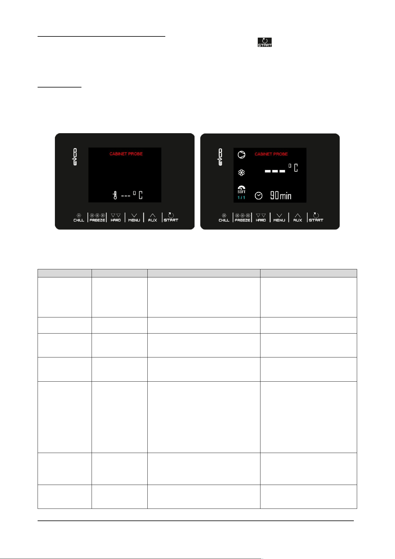
Alarms will be displayed on the Home page if their effect is to interrupt or prevent the cycle from activating; if they are such
as to allow the continuation of the current cycle, they will instead take the place of the "cycle progress bar" until they
disappear.
CODE
MEANING
CONSEGUENCES
SOLUTION
HIGH
PRESSURE
High pressure
allarm
- if the cycle in progress involves the use
of the compressor, the cycle is
interrupted
- the alarm output will be activated
- the condenser fan will be turned on.
- check the device-input
connection
- check the state of pressostat
device (ref. 3 fig. 2)
DOOR OPEN
Door open allarm
- all outputs will be deactivated except
the light output and the alarm output.
- check the door condition.
HIGH
TEMPERATURE
Maximum
temperature alarm
(HACCP alarm)
- the device will memorize the alarm
- the alarm output will be activated
- check the cell temperature
LOW
TEMPERATURE
Minimum
temperature alarm
(HACCP alarm)
- the device will memorize the alarm
- the alarm output will be activated
- check the cell temperature
CYCLE
DURATION
Alarm for
temperature-
controlled chilling
or temperature-
controlled freezing
not completed
within the
maximum duration
(HACCP alarm)
- the device will memorize the alarm
- the alarm output will be activated.
POWER
FAILURE
Power failure
alarm (HACCP
alarm)
- the device will memorize the alarm
- any cycle in progress will resume when
the power is restored
- the alarm output will be activated.
- check the device-power
connection
INS NEEDLE
PROBRE
SANITIZATION
Sanitization alarm
- the sanitization cycle will be interrupted
- check the correct insertion of the
needle probe

BCB US Rev.00 09-2024 pag. 49
DURATION
SANITAZATION
Sanitization alarm
not completed
within the
maximum duration
of the first phase.
- the device will memorize the alarm
- the cycle in progress will be interrupted
- the alarm output will be activated.
INS NEEDLE
PROBE
Pin probe not
inserted alarm
- the temperature cycle in progress is
switched to a timed cycle
- check the correct insertion of the
needle probes
COMUNICATION
ALLARM
User interface-
control module
communication
error
- all outputs will be deactivated
- check the user interface-control
module connection
8.4.2– ERRORS
CODE
MEANING
CONSEGUENCES
SOLUTION
RTC
Clock error
- the device will not store the date and
time when an HACCP alarm occurred
- the alarm output will be activated.
-set the day and real time again.
ROOM PROBE
Room probe error
-if the error occurs during the “stand-by”
state, it will not be possible to start any
operating cycle
- if the error occurs during blast chilling
or freezing, the cycle continues and the
compressor operates continuously
- if the error occurs during storage, the
compressor operates at 10 minute
intervals
- if the error occurs during a defrosting
cycle, the cycle is interrupted
- the minimum temperature alarm will
never be activated
- the maximum temperature alarm will
never be activated
- the door resistors will never be turned
on
- the alarm output will be activated.
- check the integrity of the probe
- check the device-probe connection
- check the cell temperature.
EVAPORATOR
PROBE
Evaporator probe
error
- defrosting will last the time set
- parameter F1 will have no effect
- the alarm output will be activated
- check the integrity of the probe
- check the device-probe connection
- check the evaporator temperature.
NEEDLE
PROBE
Needle probe
error
- if the error occurs during the “stand-by”
state, the temperature operating cycles
will be started in time
- if the error occurs during temperature-
controlled blast chilling, blast chilling will
last by time
- if the error occurs during temperature-
controlled freezing, freezing will last by
time
- if the error occurs during the heating of
the needle probe, heating will be
interrupted
- the alarm output will be activated.
- check the integrity of the probe
- check the device-probe connection
- check the needle temperature.
BCB US Rev.00 09-2024 pag. 50
9 – DECOMMISSIONING
9.1 – PREPARATION FOR DECOMISSIONING
WARNING
Do not use means to accelerate the defrosting process or to clean, other than
those recommended by the manufacturer.
The appliance shall be stored in a room without continuously operating ignition
sources (for example: open flames, an operating gas appliance or an operating
electric heater).
Do not pierce or burn.
Be aware that refrigerants may not contain an odour.
Before carrying out this procedure, it is essential that the technician is completely familiar with the equipment and all its
detail. It is recommended good practice that all refrigerants are recovered safely. Prior to the task being carried out, an
oil and refrigerant sample shall be taken in case analysis is required prior to re-use of recovered refrigerant. It is essential
that electrical power is available before the task is commenced.
- Become familiar with the equipment and its operation.
- Isolate the system electrically.
- Before attempting the procedure, ensure that:
i) mechanical handling equipment is available,
ii) all personal protective equipment is available and being used correctly;
iii) the recovery process is supervised at all times by a competent person;
iv) recovery equipment and cylinders conform to the appropriate standards.
- Pump down refrigerant system, if possible.
- If a vacuum is not possible, make a manifold so that refrigerant can be removed from various parts of the system.
- Make sure that cylinder is situated on the scales before recovery takes place.
- Start the recovery machine and operate in accordance with instructions.
- Do not overfill cylinders (no more than 80 % volume liquid charge).
- Do not exceed the maximum working pressure of the cylinder, even temporarily.
- When the cylinders have been filled correctly and the process completed, make sure that the cylinders and the
equipment are removed from site promptly and all isolation valves on the equipment are closed off.
- Recovered refrigerant shall not be charged into another refrigerating system unless it has been cleaned and
checked.
Prior to beginning work on systems containing flammable refrigerants, safety checks are necessary to ensure that the
risk of ignition is minimised. For repair to the REFRIGERATING SYSTEM, Clauses ‘Work procedure’ to ‘No ignition
sources’ shall be completed prior to conducting work on the system.
Work shall be undertaken under a controlled procedure so as to minimise the risk
of a flammable gas or vapour being present while the work is being performed.
All maintenance staff and others working in the local area shall be instructed on
the nature of work being carried out. Work in confined spaces shall be avoided.
The area shall be checked with an appropriate refrigerant detector prior to and
during work, to ensure the technician is aware of potentially toxic or flammable
atmospheres.
Ensure that the leak detection equipment being used is suitable for use with all
applicable refrigerants, i.e., nonsparking, adequately sealed, or intrinsically safe.
BCB US Rev.00 09-2024 pag. 51
If any hot work is to be conducted on the refrigerating equipment or any
associated parts, appropriate fire extinguishing equipment shall be available on
hand. A dry chemical or CO2 fire extinguisher should be adjacent to the charging
area.
No person carrying out work in relation to a REFRIGERATING SYSTEM which
involves exposing any pipe work shall use any sources of ignition in such a
manner that it may lead to the risk of fire or explosion. All possible ignition
sources, including cigarette smoking, should be kept sufficiently far away from the
site of installation, repairing, removing and disposal, during which refrigerant can
possibly be released to the surrounding space. Prior to work taking place, the area
around the equipment shall be surveyed to make sure that there are no flammable
hazards or ignition risks. “No Smoking” signs shall be displayed.
Under no circumstances shall potential sources of ignition be used in the
searching for or detection of refrigerant leaks. A halide torch (or any other detector
using a naked flame) shall not be used.
Under no circumstances shall potential sources of ignition be used in the searching for or detection of refrigerant leaks. A
halide torch (or any other detector using a naked flame) shall not be used.
The following leak detection methods are deemed acceptable for all refrigerant systems.
Electronic leak detectors may be used to detect refrigerant leaks but, in the case of FLAMMABLE REFRIGERANTS, the
sensitivity might not be adequate, or might need recalibration. (Detection equipment shall be calibrated in a
refrigerantfree area.) Ensure that the detector is not a potential source of ignition and is suitable for the refrigerant used.
Leak detection equipment shall be set at a percentage of the LFL of the refrigerant and shall be calibrated to the
refrigerant employed, and the appropriate percentage of gas (25 % maximum) is confirmed.
Leak detection fluids are also suitable for use with most refrigerants but the use of detergents containing chlorine shall be
avoided as the chlorine can react with the refrigerant and corrode the copper pipe-work.
NOTE Examples of leak detection fluids are
– bubble method,
– fluorescent method agents.
If a leak is suspected, all naked flames shall be removed/extinguished.
If a leakage of refrigerant is found which requires brazing, all of the refrigerant shall be recovered from the system, or
isolated (by means of shut off valves) in a part of the system remote from the leak. Removal of refrigerant shall be
according to 9.1 “REMOVAL AND EVACUATION”.
9.2 REMOVAL AND EVACUATION
When breaking into the refrigerant circuit to make repairs – or for any other purpose – conventional procedures shall be
used. However, for flammable refrigerants it is important that best practice be followed, since flammability is a
consideration. The following procedure shall be adhered to:
a) safely remove refrigerant following local and national regulations;
b) purge the circuit with inert gas;
c) evacuate;
d) purge with inert gas;
e) open the circuit by cutting or brazing.
The refrigerant charge shall be recovered into the correct recovery cylinders if venting is not allowed by local and
national codes. For appliances containing flammable refrigerants, the system shall be purged with oxygen-free nitrogen
to render the appliance safe for flammable refrigerants. This process might need to be repeated several times.
Compressed air or oxygen shall not be used for purging refrigerant systems.
When the final oxygen-free nitrogen charge is used, the system shall be vented down to atmospheric pressure to enable
work to take place.
Ensure that the outlet for the vacuum pump is not close to any potential ignition sources and that ventilation is available.

BCB US Rev.00 09-2024 pag. 52
9.3 RECOVERY
When removing refrigerant from a system, either for servicing or decommissioning, it is recommended good practice that
all refrigerants are removed safely.
When transferring refrigerant into cylinders, ensure that only appropriate refrigerant recovery cylinders are employed.
Ensure that the correct number of cylinders for holding the total system charge is available. All cylinders to be used are
designated for the recovered refrigerant and labelled for that refrigerant (i.e., special cylinders for the recovery of
refrigerant). Cylinders shall be complete with pressure-relief valve and associated shut-off valves in good working order.
Empty recovery cylinders are evacuated and, if possible, cooled before recovery occurs.
The recovery equipment shall be in good working order with a set of instructions concerning the equipment that is at
hand and shall be suitable for the recovery of all appropriate refrigerants including, when applicable, FLAMMABLE
REFRIGERANTS. In addition, a set of calibrated weighing scales shall be available and in good working order. Hoses
shall be complete with leak-free disconnect couplings and in good condition. Before using the recovery machine, check
that it is in satisfactory working order, has been properly maintained and that any associated electrical components are
sealed to prevent ignition in the event of a refrigerant release. Consult manufacturer if in doubt.
The recovered refrigerant shall be returned to the refrigerant supplier in the correct recovery cylinder, and the relevant
waste transfer note arranged. Do not mix refrigerants in recovery units and especially not in cylinders.
If compressors or compressor oils are to be removed, ensure that they have been evacuated to an acceptable level to
make certain that FLAMMABLE REFRIGERANT does not remain within the lubricant. The evacuation process shall be
carried out prior to returning the compressor to the suppliers. Only electric heating to the compressor body shall be
employed to accelerate this process. When oil is drained from a system, it shall be carried out safely
9.4 LABBELING
Equipment shall be labelled stating that it has been de-commissioned and emptied of refrigerant. The label shall be
dated and signed. Ensure that there are labels on the equipment stating the equipment contains flammable refrigerants
BCB US Rev.00 09-2024 pag. 53
10 – DISPOSAL
10.1 – DISPOSAL METHOD
APPLIANCE STATUS
- electronic circuit board in position “O” (OFF);
- I/O main switch in position “O” (OFF);
- power supply plug disconnected from the mains.
METHOD
The appliance is made of ferrous materials, electronic components and plastics. If it needs to be disposed of, separate
the various components according to the material of which they are made, to simplify separate waste collection or re-use
of the parts. The appliance must be disposed of separately from urban waste.
No special instructions apply to the dismantled appliance. Dispose of it through the special operators or return to the
dealer, if the law provides for this (also see “Information to users regarding waste disposal in the European Union” below).
For disposal consult the laws applicable in the country where the appliance is used (also see “Information to users regarding
waste disposal in the European Union” below).
TAKE CARE: THE APPLIANCE CONTAINS REFRIGERANT GAS THAT MUST BE
CONTROLLED AND RECOVERED ACCORDING TO THE REGULATIONS OF THE COUNTRY
IN WHICH DISPOSAL WILL TAKE PLACE.
Consult the fitter for any dismantling requirements.
INFORMATION TO USERS REGARDING WASTE DISPOSAL IN THE EUROPEAN UNION
The symbol of a crossed waste bin on the appliance indicates that at the end of its working life the product must be collected
separately from other waste.
Therefore, at the end of the product’s working life the user must take it to a suitable centre for the collection of electronic
and electrical waste, or return it to a dealer when purchasing a new appliance of the same type.
Suitable separate waste collection of unwanted appliances and their forwarding to treatment, recovery and
environmentally friendly disposal makes it possible to avoid potential negative effects on the environment and human
health, and assists recycling and recovery of materials.
Unauthorized disposal of the product by the user is punished by the application of fines established by the countries in
which the appliance is disposed of.

BCB US Rev.00 09-2024 pag. 54
11 – SPARE PARTS
11.1 – ORDERING SPARE PARTS
Contact the manufacturer or authorized dealer to order spare parts.
12 – APPENDICES
The appliance comes with the following appendices:
- Electrical diagram
- Electrical approval report
- Assessment of vacuum, leakage and gas loading for cooling unit.
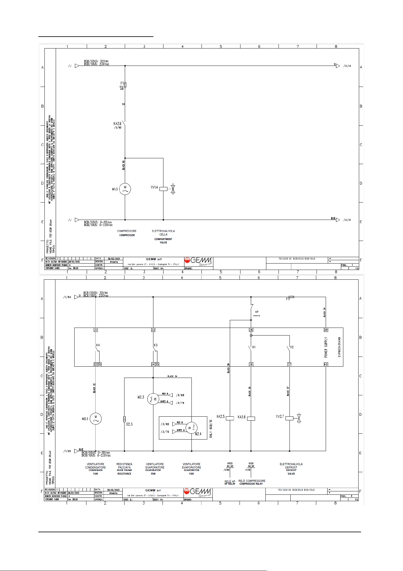
BCB US Rev.00 09-2024 pag. 55
BCB/05US and BCB/10US WIRING DIAGRAM
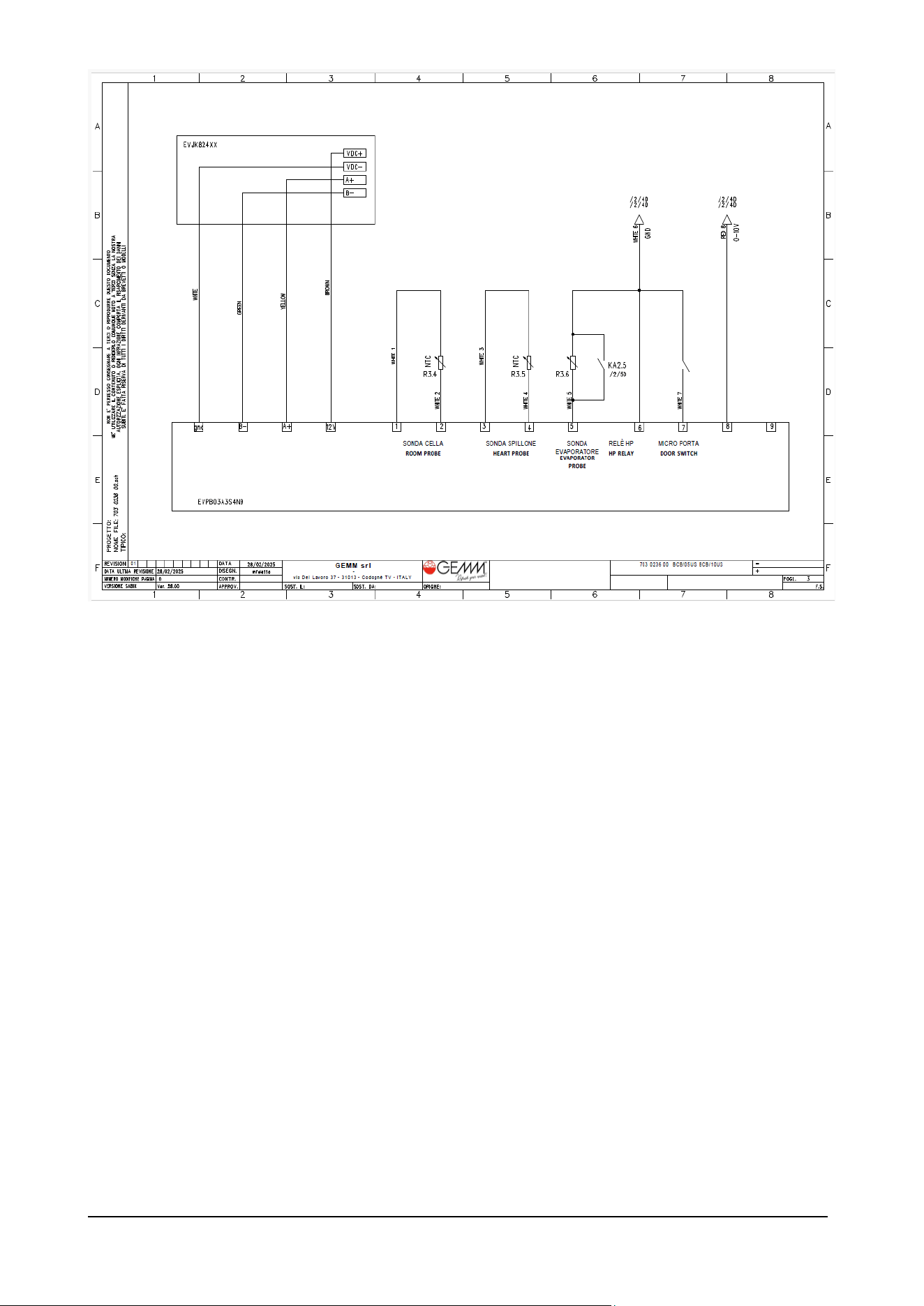
BCB US Rev.00 09-2024 pag. 56
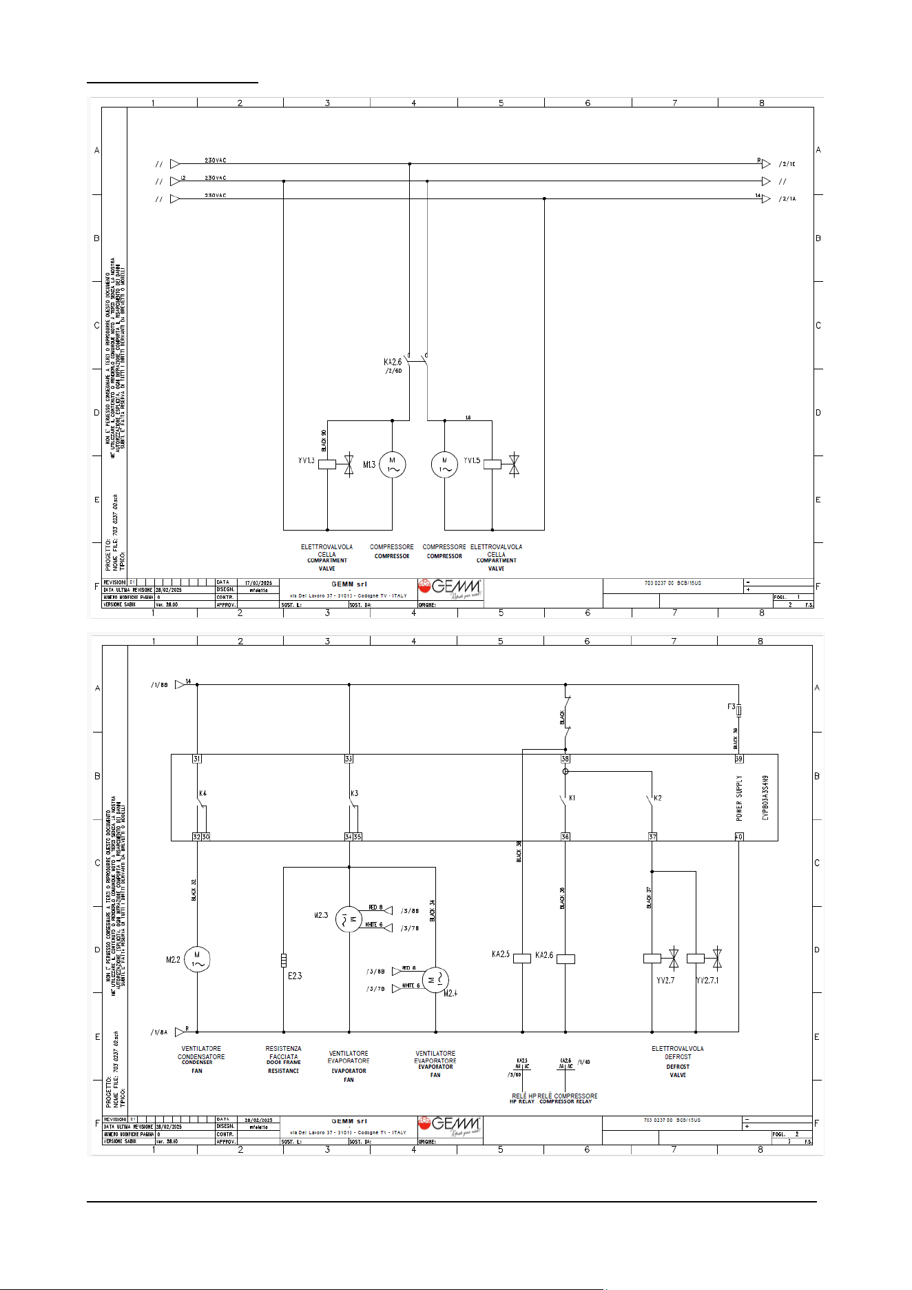
BCB US Rev.00 09-2024 pag. 57
BCB/15US WIRING DIAGRAM
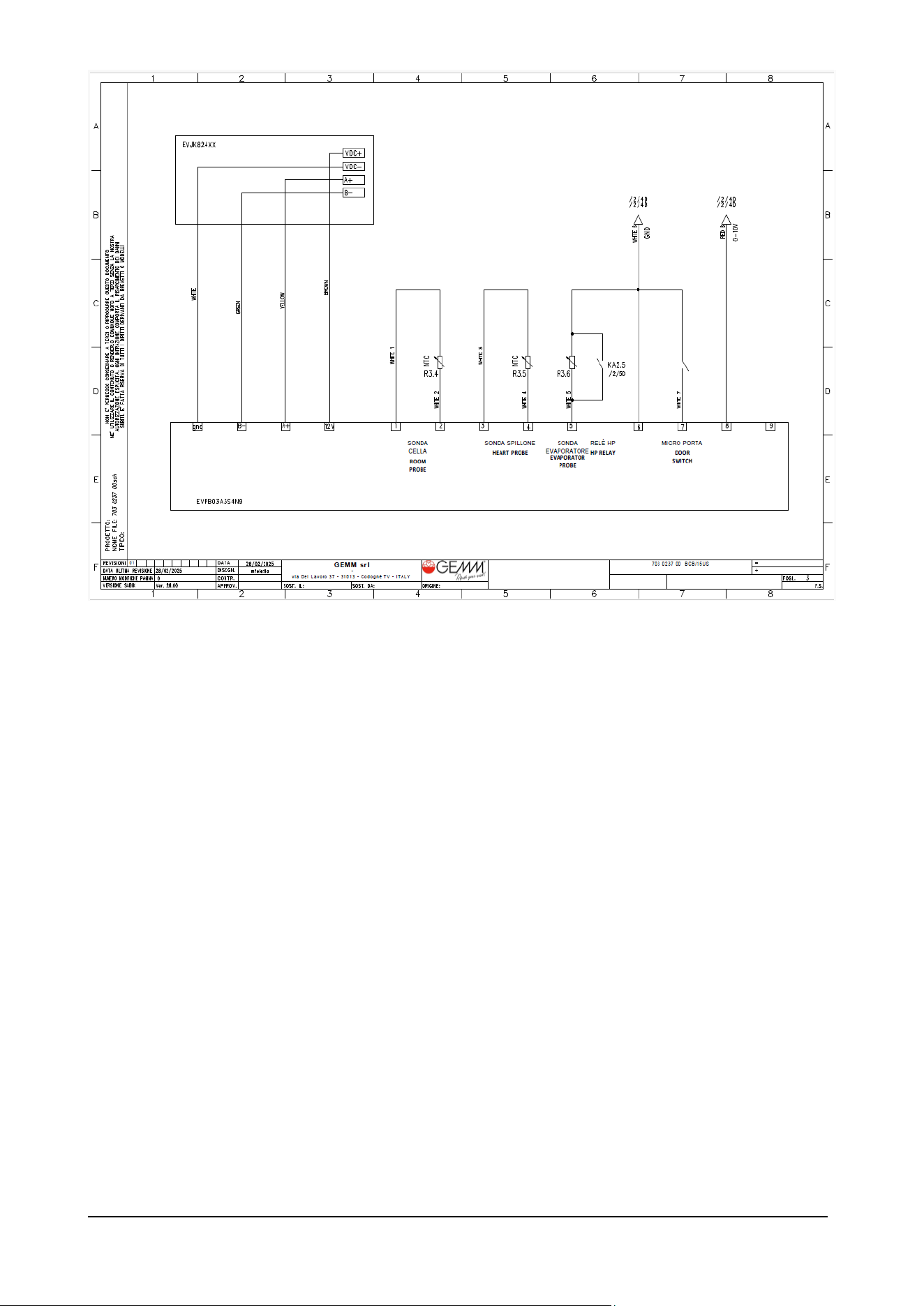
BCB US Rev.00 09-2024 pag. 58


GEMM srl
Via del Lavoro, 37 - Loc. Cimavilla - 31013 CODOGNE' (TV) - ITALY
T. +39 0438 778504 – F. +39 0438 470249
e-mail: [email protected] - www.gemm-srl.com
Iscr.Reg.Impr. TV - CF e P.IVA 03441880261 - REA TV 272556
Registro Prod. AEE-TV n IT08020000001108