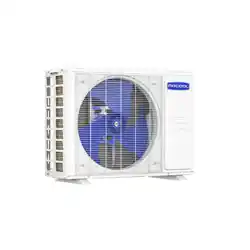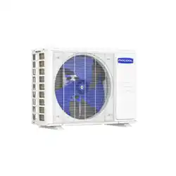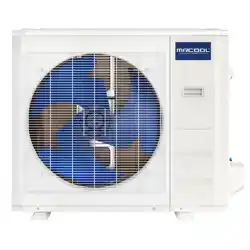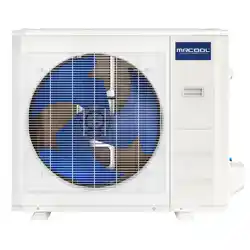
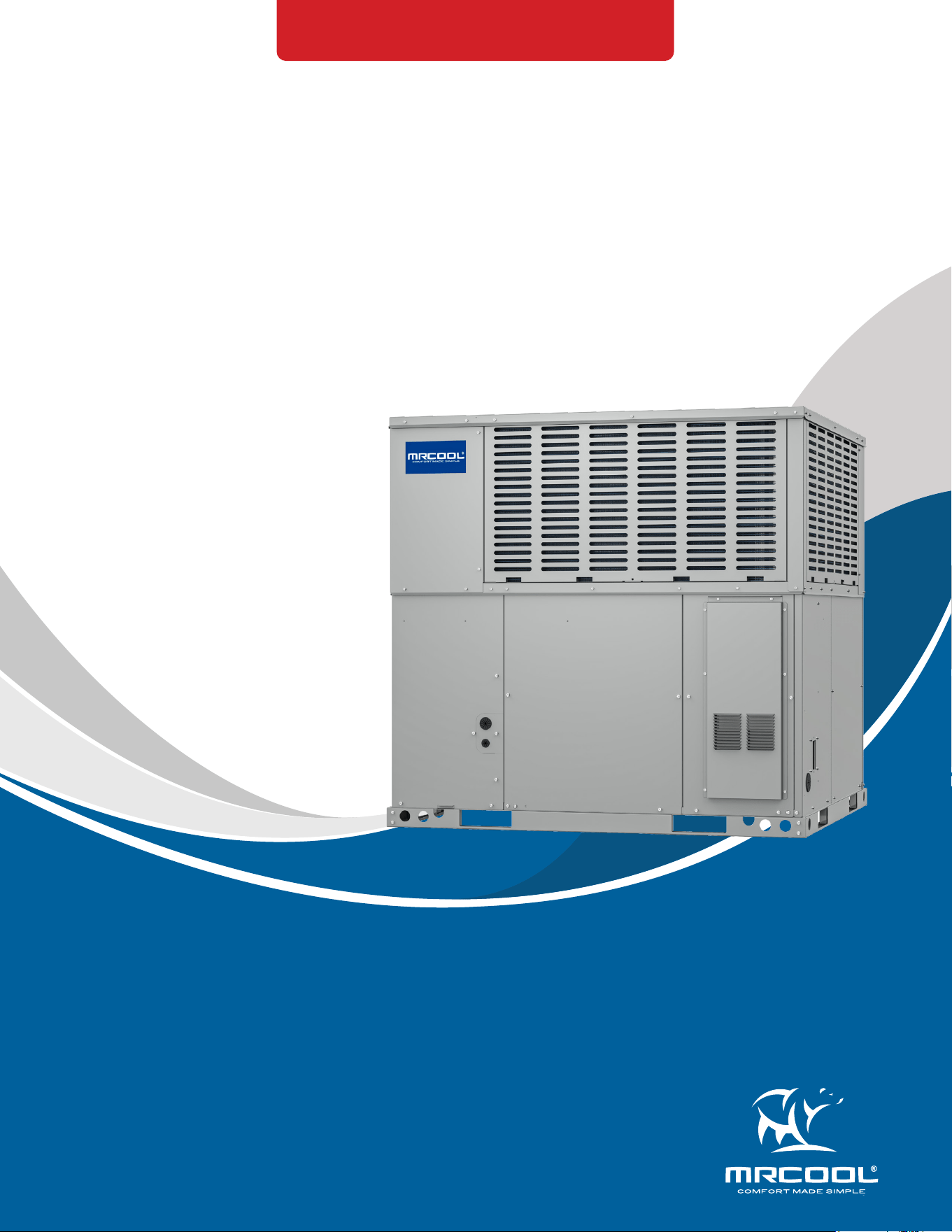
VersaPro
®
Gas Packaged Unit
Service Manual
MODELS:
Read this manual carefully before installation and keep it where
the operator can easily nd it for future reference.
Due to updates and constantly improving performance, the
information and instructions within this manual are subject to
change without notice.
Version Date: April 14, 2025
Please visit www.mrcool.com/documentation
to ensure you have the latest version of this manual.
• MPG*S*MO13C
This product utilizes R-454B refrigerant
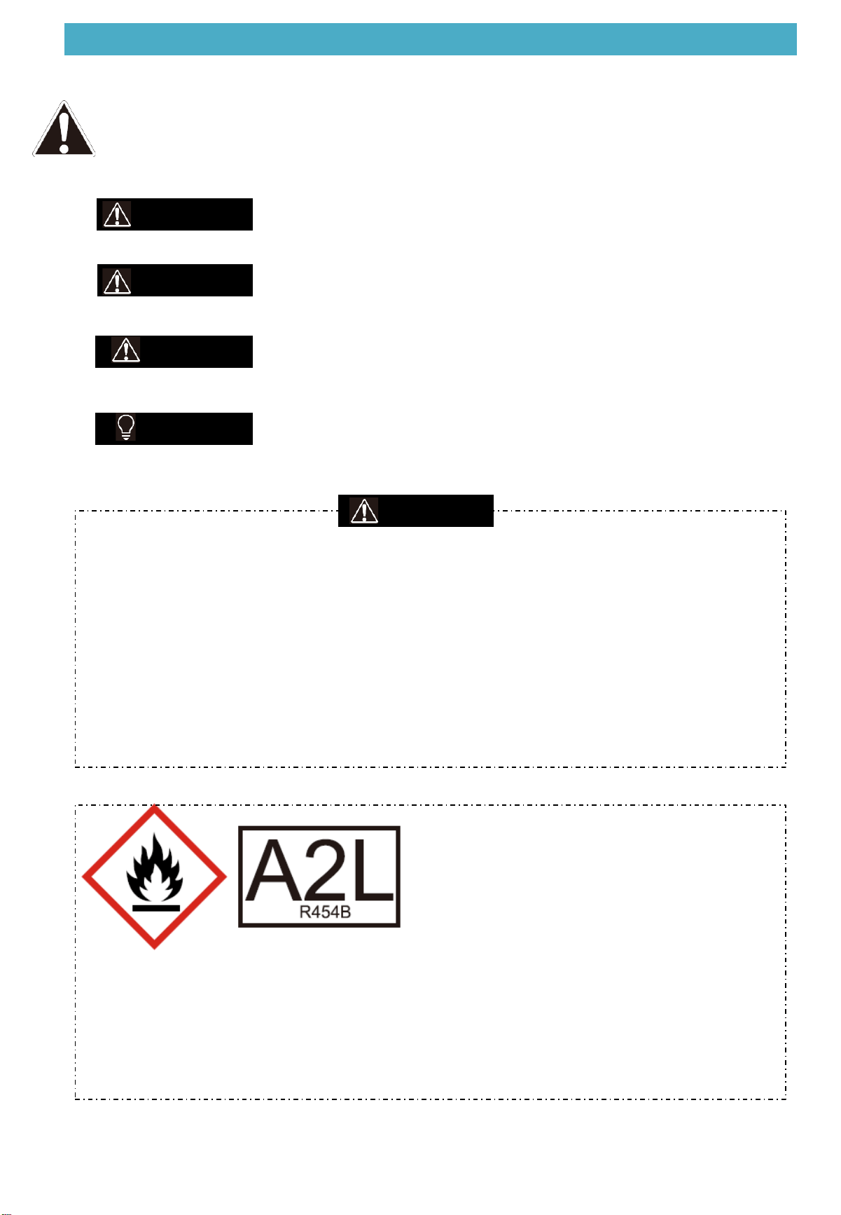
Safety
Safety Signs
This is the general warning sign. It is used to alert the user to potential hazards. All safety messages that
follow this sign shall be obeyed to avoid possible harm.
DANGER
Indicates a hazard with a high level of risk which, if not avoided, will result in death or serious injury.
WARNING
Indicates a hazard with a medium level of risk which, if not avoided, could result in death or serious injury.
CAUTION
Indicates a hazard with a low level of risk which, if not avoided, could result in minor or moderate injury.
NOTE
A situation that may cause damage to the equipment or loss of property.
Work on the refrigerant circuit with flammable refrigerant in safety group A2L may only be carried out by
authorized contractors. These heating contractors must be trained in accordance with UL 60335-2-40,
Section HH. The certificate of competence from an industry accredited body is required.
Work on electrical equipment may only be carried out by a qualified electrician.
Before initial commissioning, all safety – related points must be checked by the particular certified heating
contractors. The system must be commissioned by the system installer or a qualified person authorized by
the installer.
For installation of the unit, refer to the corresponding installation and operation manual. If an unit is
installed in an unventilated area, the area shall be so constructed that should any refrigerant leak, it
will not stagnate so as to create a fire or explosion hazard.
The appliance shall be stored so as to prevent mechanical damage from occurring.
Do not stack combustible materials on the surface of the unit.
WARNING
Do not use means to accelerate the defrosting process or to clean, other than those recommended by the
manufacturer.
The appliance shall be stored in a room that does not have continuously operating ignition sources (for
example: open flames, an operating gas appliance or an operating electric heater).
Do not pierce or burn the unit.
Be aware that refrigerants may not contain an odour.
If refrigerant gas leaks during installation, ventilate the area immediately.
Comply with national gas regulations.
Safety
Safety Precautions
This appliance is not intended for use by persons (including children) with reduced physical, sensory or
mental capabilities, or persons who lack experience and knowledge, unless they are supervised or have been
given instructions concerning the use of the appliance by a person responsible for their safety. Children
should be supervised to ensure that they do not play with the appliance.
Any person who is involved with working on or opening a refrigerant circuit should hold a current valid
certificate from an industry-accredited assessment authority, which authorizes their competence to handle
refrigerants safely in accordance with an industry recognized assessment credential.
Servicing shall only be performed as recommended by the equipment manufacturer.
Maintenance and repair requiring the assistance of other skilled personnel shall be carried out under the
supervision of a person competent in the use of flammable refrigerants.
Prior to beginning work on systems containing flammable refrigerants, safety checks are necessary to
minimize the risk of ignition.
When repairing the refrigerating system, comply with the following precautions prior to conducting
work on the system:
– shall be undertaken according to controlled procedures so as to minimize the risk of the presence of
flammable gases or vapors while the work is being performed.
– All maintenance staff and others working in the local area shall be instructed on the nature of work being
carried out. Work in confined spaces shall be avoided.
– The area shall be checked with an appropriate refrigerant detector prior to and during work, to ensure the
technician is aware of potentially toxic or flammable environment. Ensure that the leak detection equipment
being used is suitable for use with all applicable refrigerants, i.e. non-sparking, adequately sealed or
intrinsically safe.
– If any hot work is to be conducted on the refrigerating equipment or any associated parts, appropriate fire
extinguishing equipment shall be available and easily accessible. Have a dry powder or CO2 fire extinguisher
adjacent to the charging area.
– When carrying out work in relation to a refrigerating system that involves exposing any pipe work, no
sources of ignition shall be used in such a manner that it may lead to the risk of fire or explosion. All possible
ignition sources, including cigarette smoking, should be kept sufficiently far away from the site of installation,
repair, or removal and disposal of the unit, during which refrigerant can possibly be released into the
surrounding space. Prior to beginning work, the area around the equipment is to be surveyed to make sure
that there are no flammable hazards or ignition risks. “No Smoking” signs shall be clearly displayed.
Ensure that the area is in the open or that it is adequately ventilated before opening the system or
conducting any hot work. A degree of ventilation shall continue during the period that the work is carried
out. The ventilation should safely disperse any released refrigerant and preferably expel it externally into the
surroundings.
Where electrical components are being changed, they shall be fit according to their purpose and to the
correct specification. At all times the manufacturer’s maintenance and service guidelines shall be followed. If
in doubt, consult the manufacturer’s technical department for assistance. The following checks shall be
applied to installations using flammable refrigerants:
– The actual refrigerant charge is in accordance with the room size within which the refrigerant containing
parts are installed;
– The ventilation machinery and outlets are operating adequately and are not obstructed.
– If an indirect refrigerating circuit is being used, the secondary circuit shall be checked for the presence of
refrigerant.
– Equipment marking must remain visible and legible. Markings and signs that are illegible shall be corrected.
Refrigerating pipe or components are installed in a position where they are unlikely to be exposed to any
substances which may corrode refrigerant containing components, unless the components are constructed
of materials that are inherently resistant to corrosion or are suitably protected against corrosion.
Repair and maintenance of electrical components shall include initial safety checks and component
inspection procedures. If a fault exists that could compromise safety, then no electrical supply shall be
connected to the circuit until the fault has been dealt with satisfactorily.
WARNING
Safety
Safety Precautions
If the fault cannot be corrected immediately but it is necessary to continue operation, an adequate
temporary solution shall be used. This shall be reported to the owner of the equipment so that
all parties are advised. Initial safety checks shall include:
– That capacitors are discharged: this shall be done in a safe manner to avoid the possibility of sparking;
– That no live electrical components and wiring are exposed while charging, recovering or purging the
system;
– That there is continuity of earthing.
Sealed electrical components shall be replaced. Intrinsically safe components must be replaced.
Check that cabling will not be subject to wear, corrosion, excessive pressure, vibration, sharp edges or any
other adverse environmental effects. The check shall also take into account the effects of aging or continual
vibration from sources such as compressors or fans.
Under no circumstances shall potential sources of ignition be used while searching for or detection of
refrigerant leaks. A halide torch (or any other detector using a naked flame) shall not be used.
Electronic leak detectors may be used to detect refrigerant leaks but, in the case of flammable refrigerants,
the sensitivity may not be adequate, or may need re-calibration. (Detection equipment shall be calibrated in
a refrigerant-free area.)Ensure that the detector is not a potential source of ignition and is suitable for the
refrigerant used.Leak detection equipment shall be set at a percentage of the LFL of the refrigerant and shall
be calibrated for the refrigerant employed, and the appropriate percentage of gas (25 % maximum) is
confirmed.
If a leak is suspected, all naked flames shall be removed/extinguished. If a leakage of refrigerant which
requires brazing is found, all of the refrigerant shall be recovered from the system, or isolated(by means of
shut off valves) in a part of the system remote from the leak.
Leak detection fluids are also suitable for use with most refrigerants but the use of detergents containing
chlorine shall be avoided as the chlorine may react with the refrigerant and corrode the copper pipe-work.
NOTE:Examples of leak detection fluids are
-bubble method,
-fluorescent method agents.
When breaking into the refrigerant circuit to make repairs - or for any other purpose-conventional
procedures shall be used. However, for flammable refrigerants it is important that best practice be followed,
since flammability is a consideration. The following procedure shall be adhered to:
- safely remove refrigerant following local and national regulations.
- evacuate.
-purge the circuit with inert gas .
- evacuate.
- continuously flush or purge with inert gas when using flame to open circuit, and.
- open the circuit.
The refrigerant charge shall be recovered into the correct recovery cylinders if venting is not allowed by local
and national codes. For appliances containing flammable refrigerants, the system shall be purged with
oxygen-free nitrogen to render the appliance safe for flammable refrigerants. This process might need
to be repeated several times. Compressed air or oxygen shall not be used for purging refrigerant
systems.
For appliances containing flammable refrigerants, refrigerants purging shall be achieved by breaking the
vacuum in the system with oxygen-free nitrogen and continuing to fill until the working pressure is achieved,
then venting to atmosphere, and finally pulling down to a vacuum. This process shall be repeated
until no refrigerant is within the system .When the final oxygen-free nitrogen charge is used, the system
shall be vented down to atmospheric pressure to enable work to take place.
The outlet for the vacuum pump shall not be close to any potential ignition sources, and ventilation shall be
available.
Ensure that contamination of different refrigerants does not occur when using charging equipment. Hoses or
lines shall be as short as possible to minimise the amount of refrigerant they contain.
Cylinders shall be kept upright. Ensure that the refrigeration system is grounded prior to charging the system
with refrigerant.
Label the system when charging is complete (if it is not already labeled).
Take extreme care not to overfill the refrigeration system.
WARNING
safety
Safety Precautions
Prior to recharging the system, it shall be pressure-tested with the appropriate purging gas. The system shall
be leak-tested on completion of charging but prior to commissioning. A follow up leak test shall be
carried out prior to leaving the site.
Before carrying out this procedure, it is essential that the technician is completely familiar with the
equipment and all its detail. It is recommended that all refrigerants are recovered safely. Prior to the task
being carried out, an oil and refrigerant sample shall be taken in case analysis is required prior to re-use of
reclaimed refrigerant. It is essential that electrical power is available before the task is commenced.
a) Become familiar with the equipment and its operation.
b) Isolate system electrically.
c) Before attempting the procedure ensure that:
– mechanical handling equipment is available, if required, for handling refrigerant cylinders;
– all personal protective equipment is available and being used correctly;
– the recovery process is supervised at all times by a competent person;
– recovery equipment and cylinders conform to the appropriate standards.
d) Pump down refrigerant system, if possible.
e) If a vacuum is not possible, make a manifold so that refrigerant can be removed from various parts of the
system.
f) Make sure that the cylinder is situated on the scales before recovery takes place.
g) Start the recovery machine and operate it in accordance with the manufacturer's instructions.
h) Do not overfill cylinders. (No more than 80% volume liquid charge).
i) Do not exceed the maximum working pressure of the cylinder, even temporarily.
j) When the cylinders have been filled correctly and the process has been completed, make sure
that the cylinders and the equipment are removed from site promptly and all isolation valves on the
equipment are closed off.
k) Recovered refrigerant shall not be charged into another refrigeration system unless it has been cleaned
and checked.
Equipment shall be labeled stating that it has been de-commissioned and emptied of refrigerant. The label
shall be dated and signed. Ensure that there are labels on the equipment stating the equipment contains
flammable refrigerant.
When removing refrigerant from a system, either for servicing or decommissioning, it is recommended that
all refrigerants are removed safely.
When transferring refrigerant into cylinders, ensure that only appropriate refrigerant recovery cylinders are
employed. Ensure that the correct number of cylinders for holding the total system charge is available. All
cylinders to be used are designated for the recovered refrigerant and labelled for that refrigerant (i.e.special
cylinders for the recovery of refrigerant). Cylinders shall be complete with pressure-relief valve and
associated shut-off valves in good working order. Empty recovery cylinders are evacuated and, if possible,
cooled before recovery occurs.
The recovery equipment shall be in good working order with a set of instructions concerning the equipment
that is at hand and shall be suitable for the recovery of the flammable refrigerant. If in doubt, the
manufacturer should be consulted. In addition, a set of calibrated weighing scales shall be available and in
good working order. Hoses shall be complete with leak-free disconnect couplings and in good condition.
The recovered refrigerant shall be processed according to local legislation in the correct recovery cylinder,
and the relevant waste transfer note arranged. Do not mix refrigerants in recovery units and especially not in
cylinders.
If compressors or compressor oils are to be removed, ensure that they have been evacuated to an
acceptable level to make certain that flammable refrigerant does not remain within the lubricant. The
compressor body shall not be heated by an open flame or other ignition sources to accelerate this process.
When oil is drained from a system, it shall be carried out safely.
Do not use the air conditioner for other purposes. In order to avoid any quality deterioration, do not use the
unit for the cooling of precision instruments, food, plants, animals or works of art. Before cleaning, be sure
to stop the operation, turn the breaker off or unplug the supply cord. Otherwise, electric shock and injury
may occur. In order to avoid electric shock or fire, make sure that an earth leak detector is installed.
Never touch the air outlet or the horizontal blades while the swing flap is in operation. Your fingers may be
come caught or the unit may break down.
WARNING
Safety
Safety Precautions
Never put any objects into the air inlet or outlet.
Objects touching the fan at high speed can be dangerous.
Never inspect or service the unit by yourself.
Ask a qualified service person to perform this task.
Do not dispose of this product as unsorted municipal waste. This waste should be collected separately for
special treatment. Do not dispose of electrical appliances as unsorted municipal waste. Use separate
collection facilities. Contact your local government for information regarding the connection systems
available.
If electrical appliances are disposed of in landfills or dumps, hazardous substances can leak into the
groundwater and get into the food chain, harming your health and well-being.
To prevent refrigerant leak, contact your dealer. When the system is installed and operates in a small room,
it is required to maintain the concentration of the refrigerant below the limit, in case a leak occurs.
Otherwise, oxygen in the room may be affected, resulting in a serious accident.
The refrigerant in the air conditioner is safe and normally does not leak.
If the refrigerant leaks into the room and comes into contact with the fire of a burner, a heater or a cooker, a
harmful gas could be released.
Turn off any combustible heating devices, ventilate the room, and contact the dealer where you purchased
the unit.
Do not use the air conditioner until a service person confirms that the refrigerant leak is repaired.
Keep ventilation openings clear of obstruction.
Be sure the air conditioner is earthed.
In order to avoid electric shock, make sure that the unit is earthed and that the earth wire is not connected
to a gas or water pipe, lightning conductor or telephone earth wire.
Do not operate the air conditioner with a wet hands. An electric shock may happen.
Do not touch the heat exchanger fins. These fins are sharp and could cut you.
To avoid oxygen deficiency, ventilate the room sufficiently if equipment with a burner is used together with
the air conditioner.
Arrange the drain hose to ensure smooth drainage. Incomplete drainage may cause wetting of the building,
furniture, etc.
Never touch the internal parts of the controller.
Do not remove the blower access panel. Some parts inside are dangerous to touch, and machine troubles
may occur.
Attention is drawn to the fact that additional transportation regulations may exist with respect to equipment
containing flammable gas. The maximum number of pieces of equipment or the configuration of the
equipment permitted to be transported together will be determined by the applicable transport regulations.
Signs for similar appliances used in a work area are generally addressed by local regulations and give the
minimum requirements for the provision of safety and/or health signs for a work location.
All required signs are to be maintained and employers should ensure that employees receive suitable and
sufficient instruction and training on the meaning of appropriate safety signs and the actions that need to be
taken in connection with these signs. The effectiveness of signs should not be diminished by too many signs
being placed together. Any pictograms used should be as simple as possible and contain only essential
details.
The storage of the appliance should be in accordance with the applicable regulations or instructions,
whichever is more stringent.
Storage package protection should be constructed such a way that mechanical damage to the equipment
inside the package will not cause a leak of the REFRIGERANT CHARGE.
The maximum number of pieces of equipment permitted to be stored together will be determined by local
regulations.
Do not operate the air conditioner when using a room fumigation - type insecticide. Failure to observe this
precaution could cause the chemicals to become deposited in the unit, which could endanger the health of
those who are hypersensitive to chemicals. It may also cause the refrigerant sensor to alarm.
Do not place appliances which produce open flame in places exposed to the air flow from the unit or under
the unit. It may cause incomplete combustion or deformation of the unit due to the heat.
Do not install the air conditioner in a location where flammable gas may leak out. If the gas leaks out and
stays around the air conditioner, a fire may break out.
WARNING
Safety
Safety Precautions
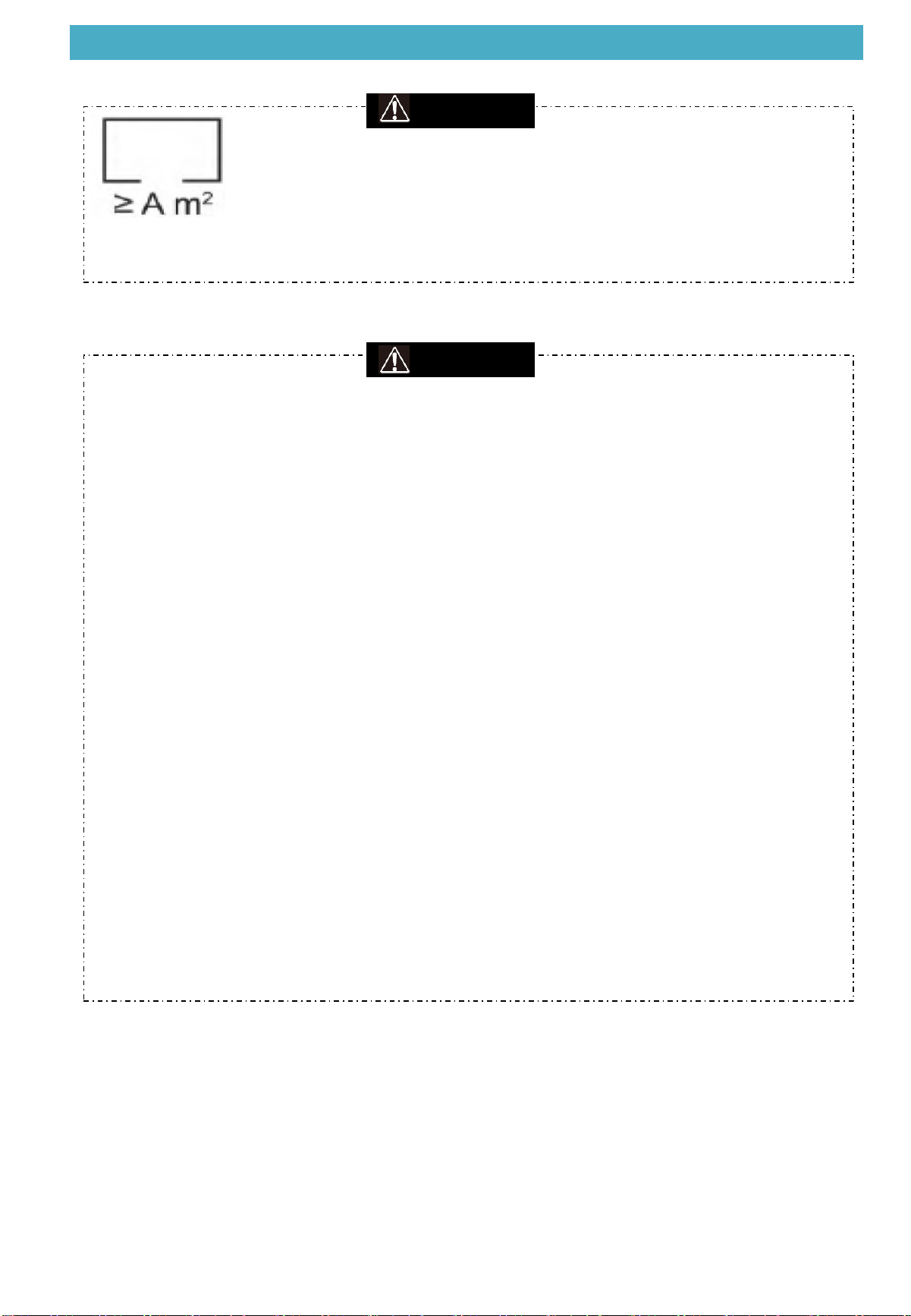
The appliance shall be installed, operated and stored in a room with a floor area not less than the minimum
room area. Refer to the installation instructions for the minimum room area required to install the appliance.
WARNING
The pipe-work including piping material, pipe routing, and installation shall include protection from physical
damage in operation and service, and be in compliance with national and local codes and standards, such as
ASHRAE 15, ASHRAE 15.2, IAPMO Uniform Mechanical Code, ICC International Mechanical Code. inspection
prior to being covered or enclosed; or CSA B52. All field joints shall be accessible for inspection prior to being
covered or enclosed.
All joints made in the installation between parts of the refrigerating system, with at least one part charged,
shall be made in accordance with the following:
— A brazed, welded, or mechanical connection shall be made before opening the valves to permit
refrigerant to flow between the refrigerating system parts. A vacuum valve shall be provided to evacuate the
interconnecting pipe or any uncharged refrigerating system part.
— Mechanical connectors used indoors shall comply with ISO 14903. When mechanical connectors are
reused indoors, sealing parts shall be renewed. When flared joints are reused indoors, the flare part shall be
refabricated.
— Refrigerant tubing shall be protected or enclosed to avoid damage.
Compliance is checked according to the installation instructions and a trial installation, if necessary.
After completion of field piping for split systems, the field pipework shall be pressure tested with an inert gas
and then vacuum tested prior to refrigerant charging, according to the following requirements.
The minimum test pressure for the low side of the system shall be the low side design pressure and the
minimum test pressure for the high side of the system shall be the high side design pressure, unless the high
side of the system, cannot be isolated from the low side of the system in which case the entire system shall
be pressure tested to the low side design pressure.
— mechanical joints in compliance with ISO 14903 or UL 207 (U.S. only).
— welded or brazed joints.
— joints in enclosures that vent to the unit or to the outside. Compliance is checked by inspection and tests.
Components and accessories from the units are not part of ordinary domestic waste.
Complete units , compressors, motors etc. are only to be disposed of via qualified disposal specialists.
This unit uses flammable refrigerant R454B. Please contact the dealer when you want to dispose of this unit.
Law requires that the collection, transportation and disposal of refrigerants must conform with the
regulations governing the collection and destruction of hydrofluorocarbons.
WARNING
Service Manual
Service Manual
PART 1 Product Instructions
PART 2 System Instruction ………………………………………………….……………………………………… 2
2.1 Refrigerant Circuit ……………………………………………………………….………………………………… 3
2.2 Functional Parts Layout ………………………………………………….……………………………………… 4
2.3 Refrigerant Flow ……………………………………………………………..…………………………………… … 6
PART 3 Function and Control …………………………………………….…………………………………… 7
3.1 Function General …………………………………………………….…….……………………………………… 8
3.1.1 Unit Shutdown Control …………………………………………….….…………………………….…….… 9
3.1.2 Unit Standby Control ………………………………………………………..……………………….…….… 9
3.1.3 Unit Normal Operation ………………………………………………..………………………………….…… 9
3.1.4 Unit Protection Control or Restart……………………….………………………..…….…….…………… 9
3.1.5 Unit Fault Control or Restart …………………………………………………..…………….………. …. 13
PART 4 Field Settings ………………………………………………….…………………………………….………… 15
4.1 Test Operation …………………………………………………………………….……………….……………… 16
4.1.1 Checks before Test Operation ………………………………………….………………………….………… 16
4.1.2 Turn Power on ………………………………………………………………….………………………..………… 17
4.2 Thermostat …………………………………………………………………………………….…….…….………… 18
PART 5 Intelligent Troubleshooting ………………………………………………………………………… 19
5.1 Diagnosis System Introduction ……………………………………………………………..…………… 20
5.2 Symptom-based Troubleshooting ……………………………………………………….….…………… 21
5.2.1 Indicator light OFF…….……………………………………………………………………….……..…………….21
5.2.2 System does not start operation ……………………………………………………..………………………22
5.2.3 Capacity is low……………………………………………………………………………………..………………….23
5.2.4 High pressure protection………………………………………………………………………..………………..24
5.2.5 Low pressure protection………………………………………………………………………..………………...25
5.2.6 Discharge temperature protection ………………………………………………………..…………………26
5.3 Trouble shooting by Main board Fault code………………………………………………….………… 27
5.3.1 System lockout(heating)………………………………………………………………………………….….27
5.3.2 Pressure switch problem detected(heating)…………………………………………….………...28
5.3.3 High limit switch protection device open(heating)……………………………………………..29
PART 6 Check ……………………………………………………………………………………………….…………… 30
6.1 Check for Causes of Rise in High Pressure …………………………..……………………….……… 31
6.2 Check for Causes of Dropping Low Pressure in Cooling ……………….…………..………… 32
6.3 Check for Causes of Refrigeration cycling Blocked ………………………………..…………… 33
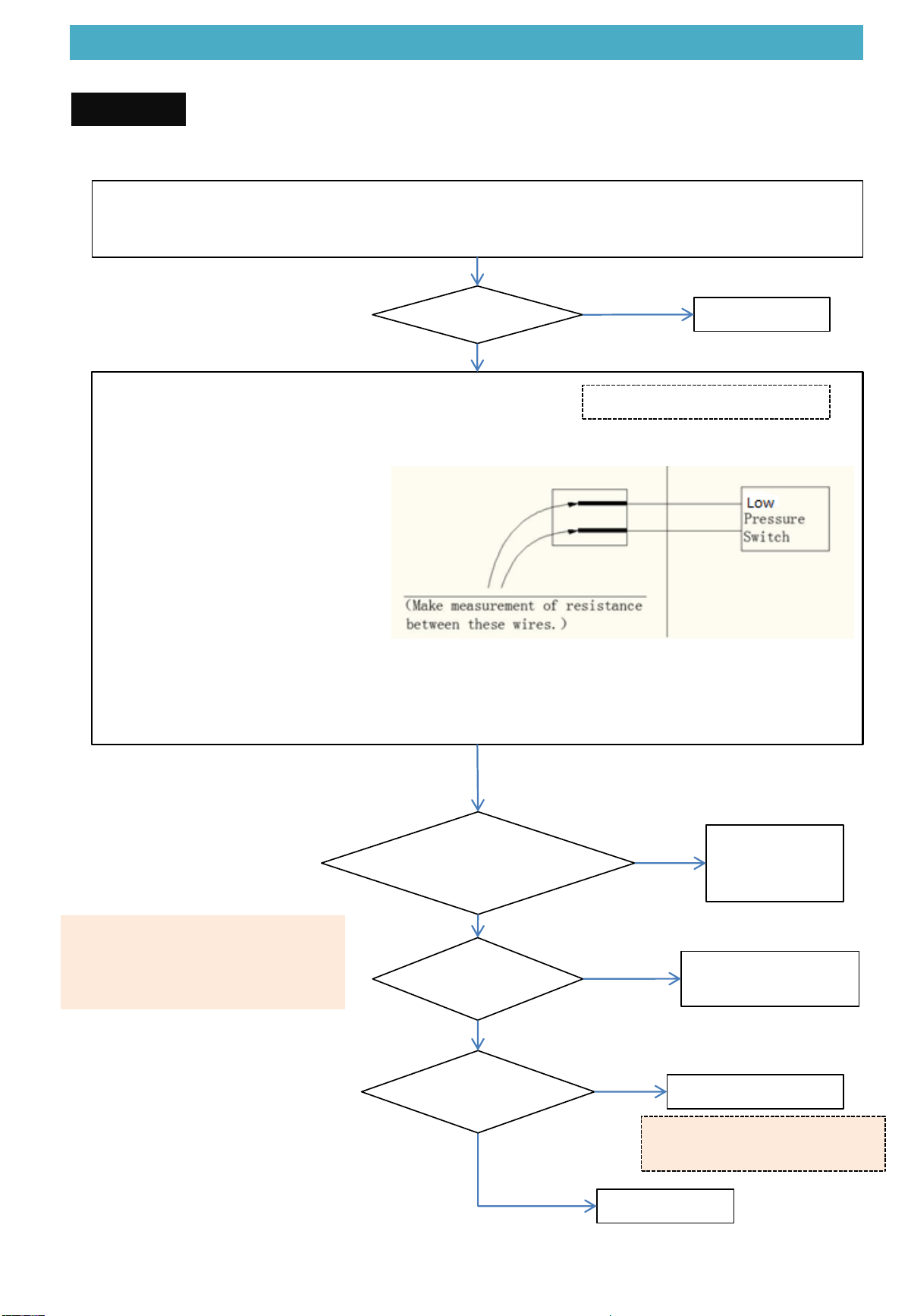
6.4 Check for High Pressure Switch (HPS) ……………………………………………………..….……… 34
6.5 Check for Low Pressure Switch (LPS) ………………………………………………….…………..… 35
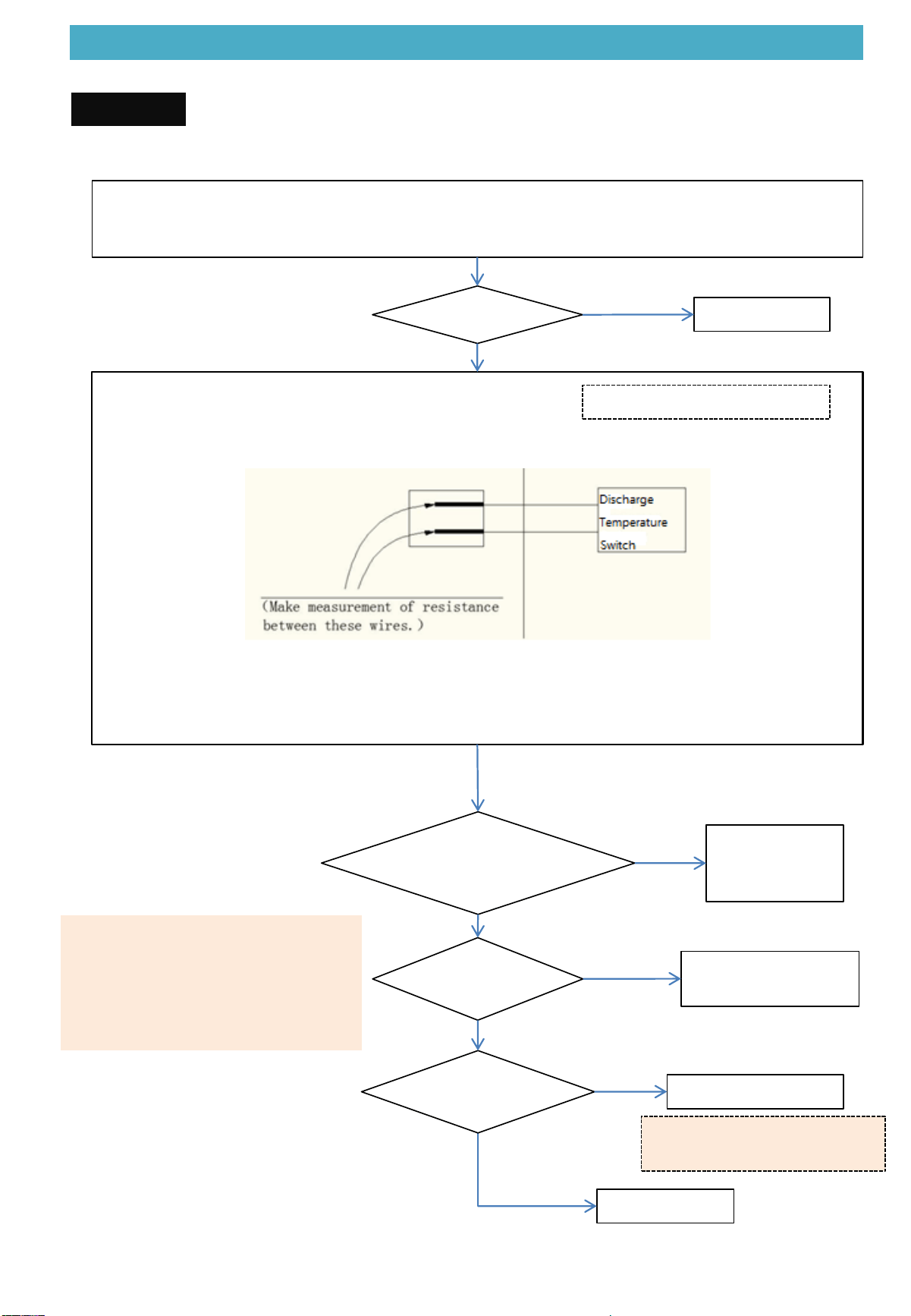
6.6 Check for Discharge Temperature Switch (T5) …………………………………….….…………… 36
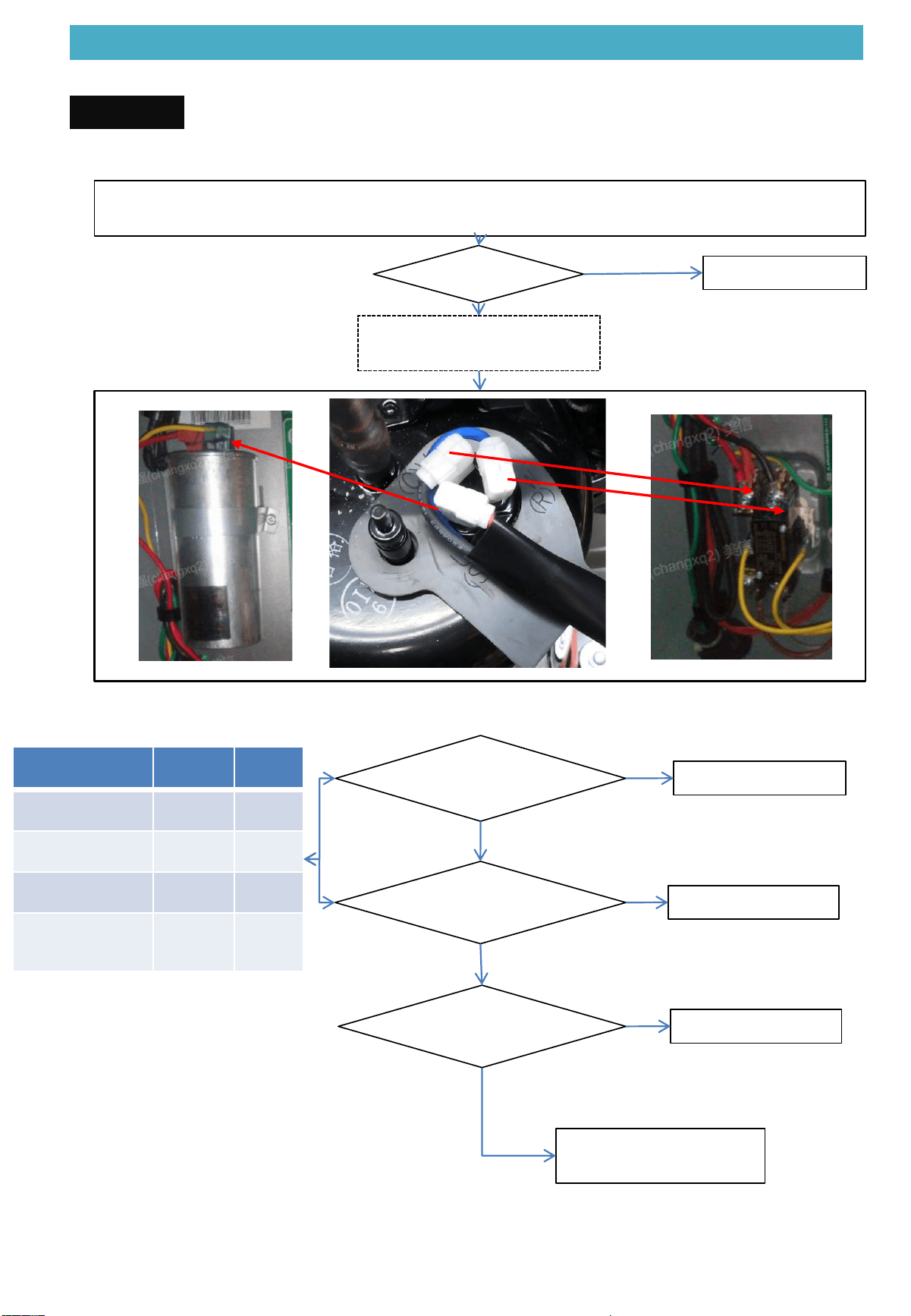
6.7 Check for Compressor Check ………………………………………………………………….…...……… 37
PART 7 Appendix……………………………………………………………………………………………….………….38
7.1 Wiring Diagrams ………………….…………………………………………………………………………………… 39
7.2 Indoor Fan replacement procedure……………………………………………………………………………46
8
2. System Instruction
9
PART 2 System Instruction…….……………………………………………………………………………… 2
2.1 Refrigerant Circuit …………………………………………………………………. ………………………… 3
2.2 Functional Part Layout……….……………………………………………………………………….…….… 4
2.3 Refrigerant Flow Chart……………………………………………………………………………….…….… 6
2. System Instruction
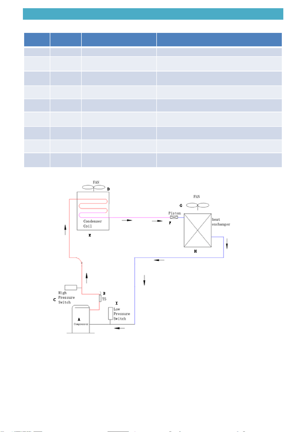
2.1 Refrigerant Circuit
10
No. in
diagram
Symbol Part Name Major function
A Comp. Compressor Compresses and drives the refrigerant.
B T5
Compressor discharge temperature
sensor
Used to discharge temperature protection
C HPS High pressure switch
Used to high pressure protection when up to 580 PSIG and
recovery when below to 435 PSIG.
D Fan Fan of outdoor Used to help heat exchange by PSC motor.
E Exchanger Exchanger of outdoor Exchange heat to the outdoor
F
throttle
valve
Piston Adjust refrigerant flow rate
G Fan Fan of indoor Used to help heat exchange by ECM motor.
H Exchanger Exchanger of indoor Take heat from the indoor
I LPS Low pressure switch
Used to low pressure protection when below to 14.5 PSIG and
recovery when up to 31.9 PSIG.
2. Refrigerant Circuit
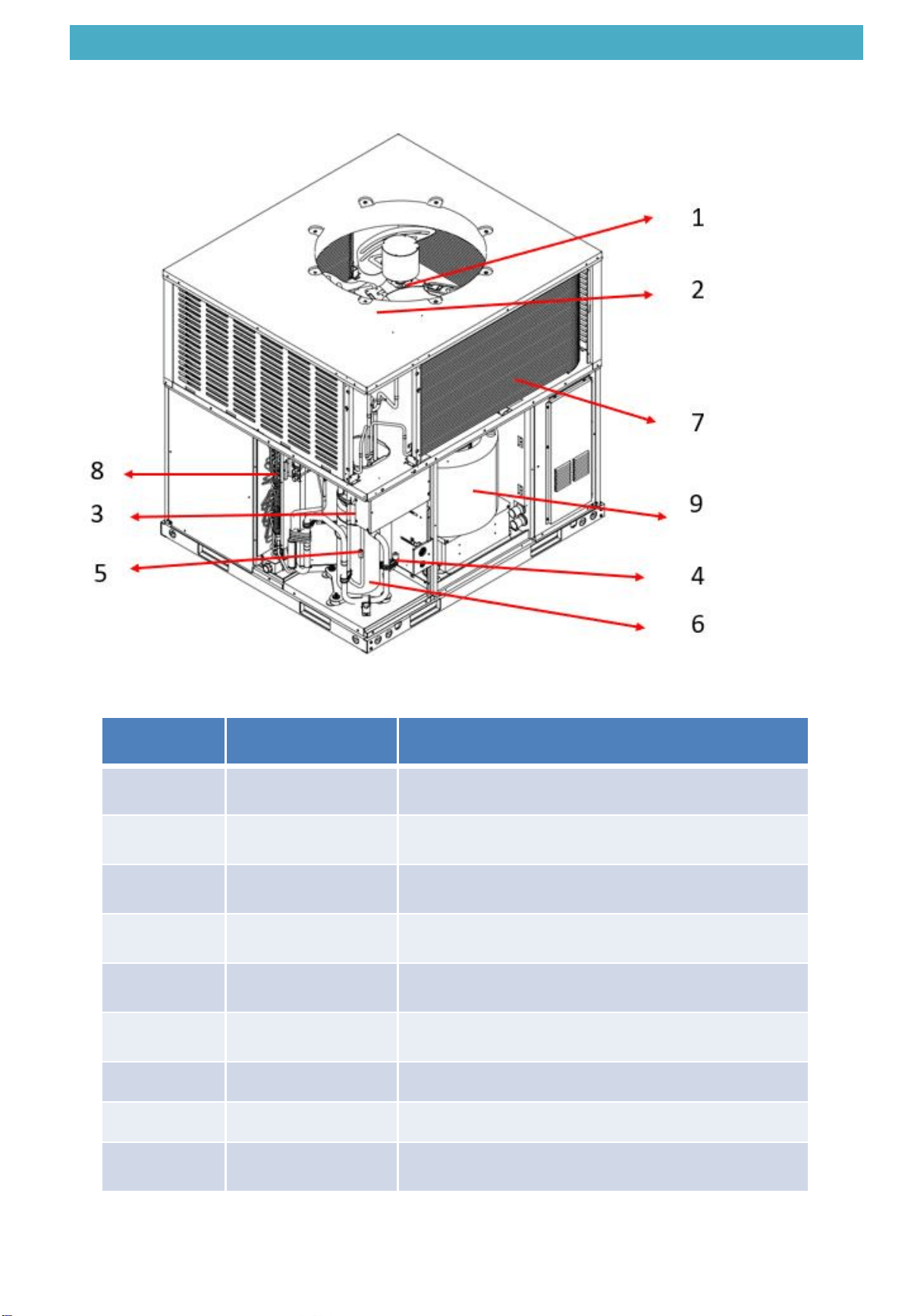
2.2 Functional Part layout
11
NO
Symbol
Part Name
1
Motor
Fan motor
2
Fan
Fan of outdoor
3
HPS
High pressure switch
4
LPS
Low pressure
switch
5
DTS
Discharge
Temperature switch
6
Comp.
Compressor
7
Cond.
Condenser
Coil
8
Evap.
Evaporator Coil
9
Fan
Fan of Indoor
2. Refrigerant Circuit
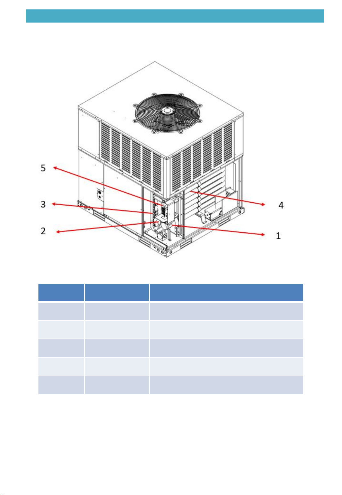
2.2 Functional Part layout
12
NO
Symbol
Part Name
1
Motor
Exhaust fan motor
2
PS
Pressure switch
3
Burner
Burner assembly
4
HEP
Heat exchange pipe
5
CB
Control board
2. Refrigerant Circuit
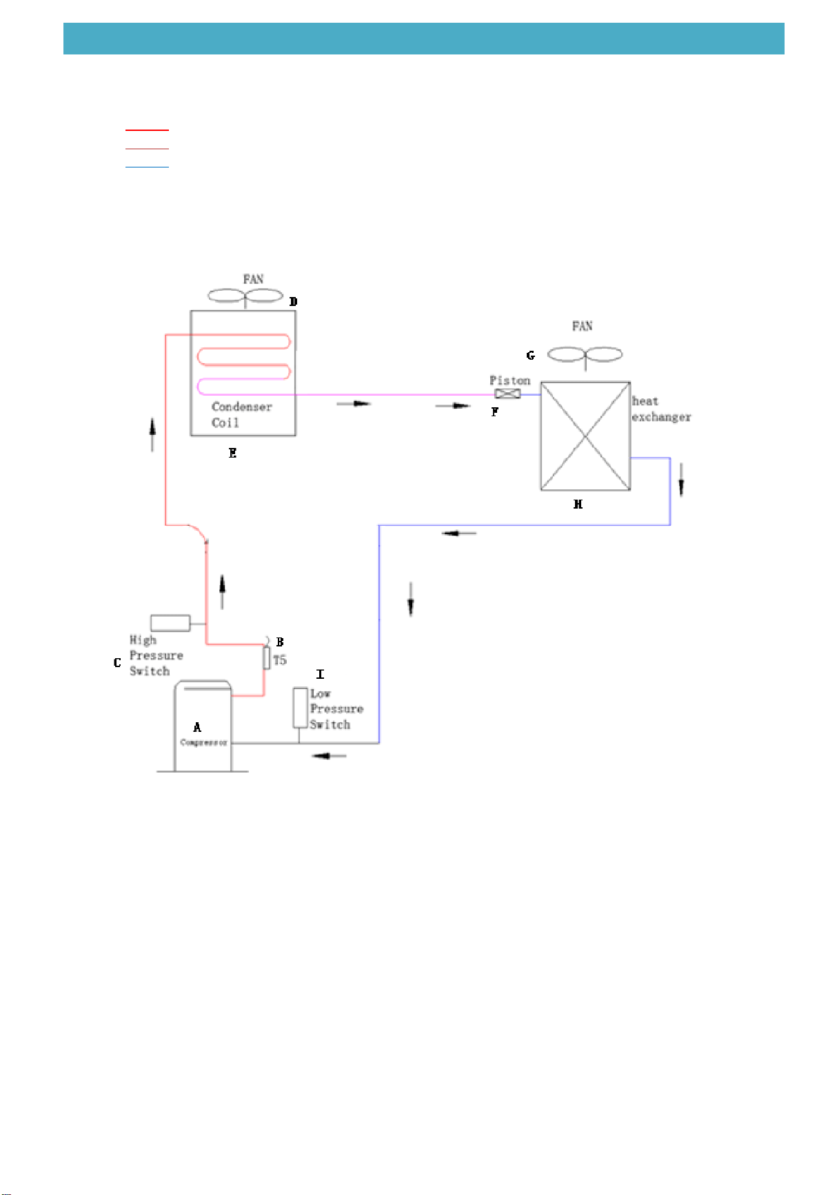
2.3 Refrigerant Flow Chart
High pressure gas
High pressure liquid
Low pressure
1
3
3. Function and Control
14
PART 3 Function and Control …………………………………………………………………………… 7
3.1 Function General …………………………………………………………………………………………… 8
3.1.1 Unit Shutdown Control ……………………………………………………………………….…….… 9
3.1.2 Unit Standby Control ………………………………………………………………………….…….… 9
3.1.3 Unit Normal Operation …………………………………………………………………………….…… 9
3.1.4 Unit Protection Control or Restart……………………….……………………….…….…………… 9
3.1.5 Unit Fault Control or Restart ………………………………………………………….………. …. 13
3. Function and Control
3.1 Function General
15
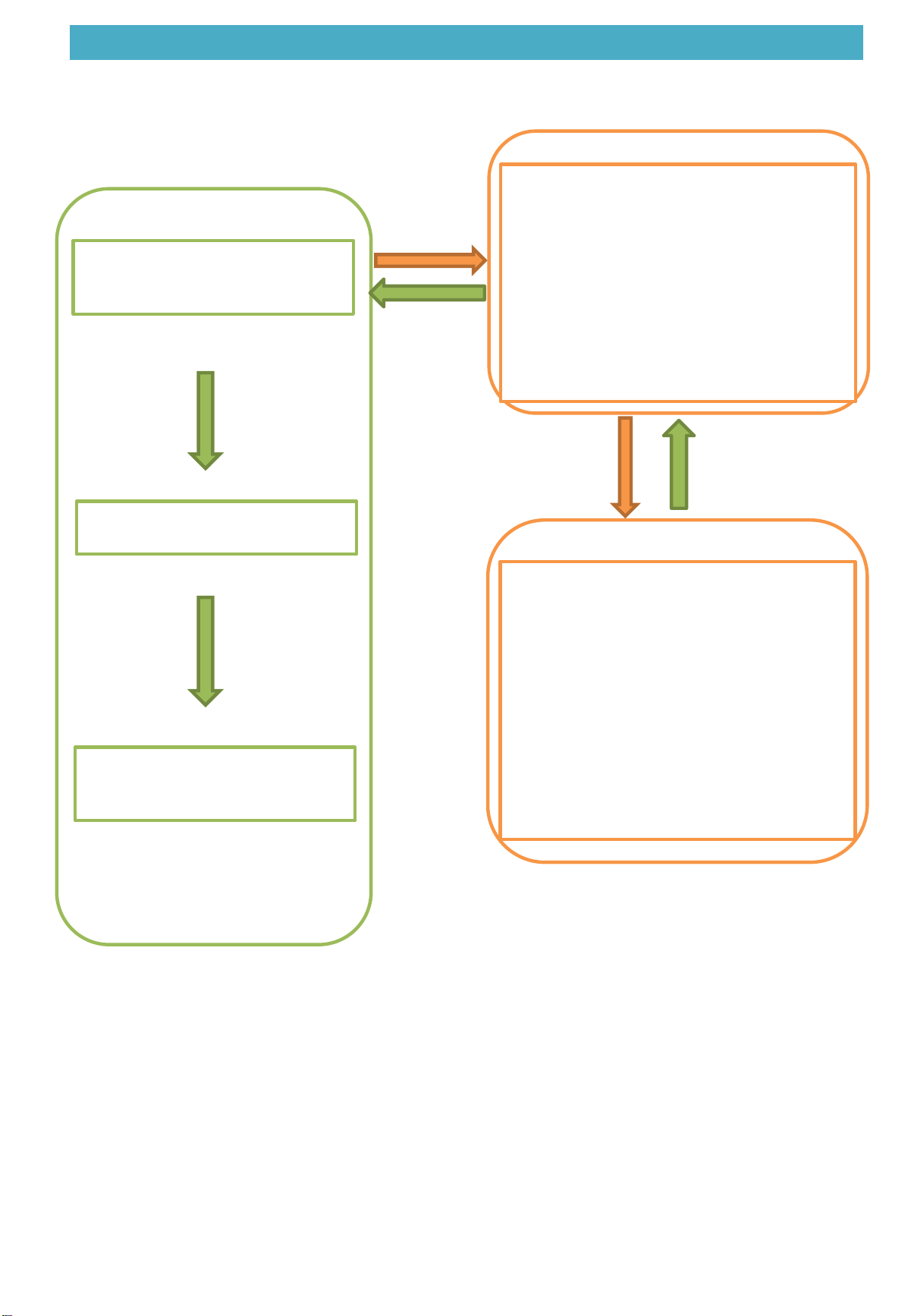
3.1.1 Unit shutdown control:
(1) Protection shutdown
(2) System stops
3.1.2 Unit standby control:
(1) Standby control
3.1.3 Unit normal operation:
(1) Cooling control
(2) Heating control
3.1.5 Unit protection control or restart
(1) Discharge Temp. Protection
(2) Low Pressure Switch Protection
(3) High Pressure Switch Protection
(4) System lockout
(5) Pressure switch problem detected
(6) High limit switch protection device
open
(7) Flame sensed and gas valve not
energized or no “W” signal
(8) Flame rollout switch open
Normal
Protection
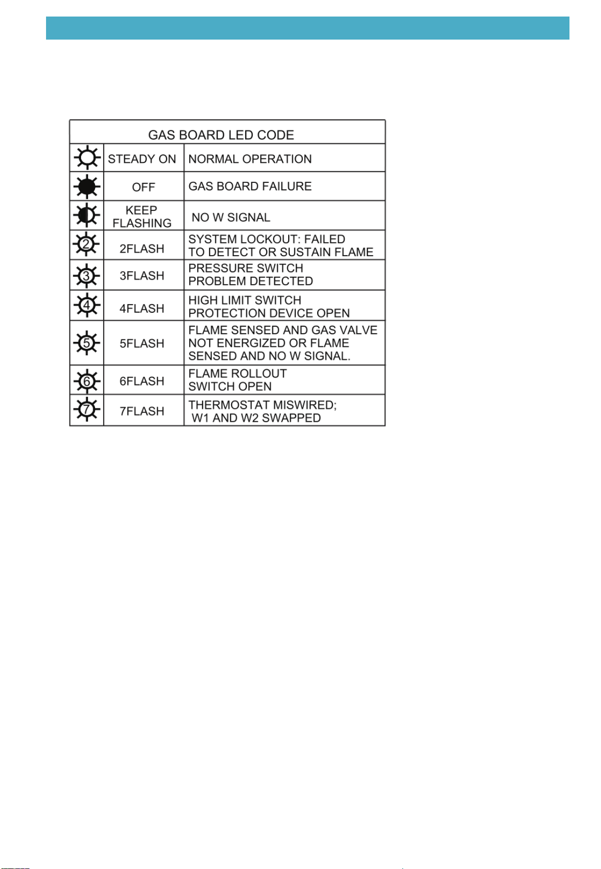
3.1.6 Fault of Main board Fault (heating ):
(1) Keep Flashing: No W signal
(2) 2 Flash: System lockout(Failed to detect
or sustain flame)
(3) 3 Flash: pressure switch problem
detected
(4) 4 Flash: High limit switch protection
device open
(5) 5 Flash: Flame sensed and gas valve not
energized or no “W” signal
(6) 6 Flash: Flame rollout switch open
(7) 7 Flash: Thermostat miswired; W1 and
W2 swapped
Fault of Main board
3. Function and Control
3.1.1 Unit shutdown control
16
⑴ Standby control
When compressor stopped, the outdoor fan would stop immediately.
When “W” signal is lost, gas valve would shutdown immediately, while smoke extraction fan and inside
fan would work for the time delay
3.1.2 Unit standby control
⑴ Unit protection shutdown
To protect the unit during heating, our system will shut down when there is something abnormal.
Also the LED would show the fault code when fault present.
⑵ Thermostat satisfied shutdown
Anytime system is in unit standby, LED will steady on .
3.1.3 Unit normal operation
(1) Reversing valve control
The unit need “R”,”C”,”G”,“Y”,”W” signal of 24V wires.
●Cooling:
“R”,”C”,”G”,“Y” signals are on.
●Heating:
“R”,”C”,”W” ” signals are on.
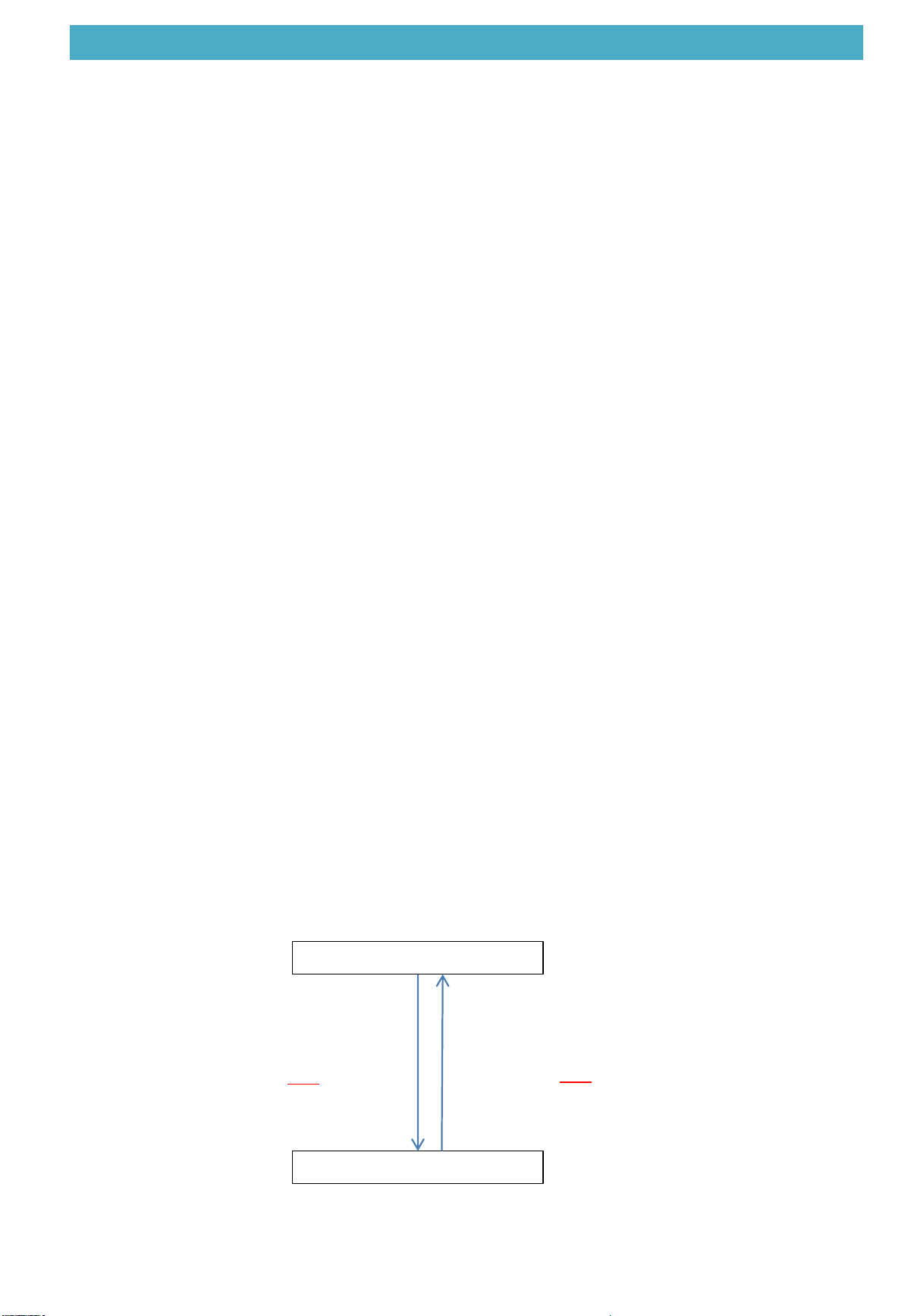
(1) Discharge Temp. Protection in cooling
Normal operation
System standby
sensor ≥239 ℉(71/90/105/120)
sensor <167 ℉(71/90/105/120)
sensor ≥257 ℉(120/140/160)
sensor <203 ℉(120/140/160)
3.1.4 Unit protection control or restart:
3. Function and Control
17
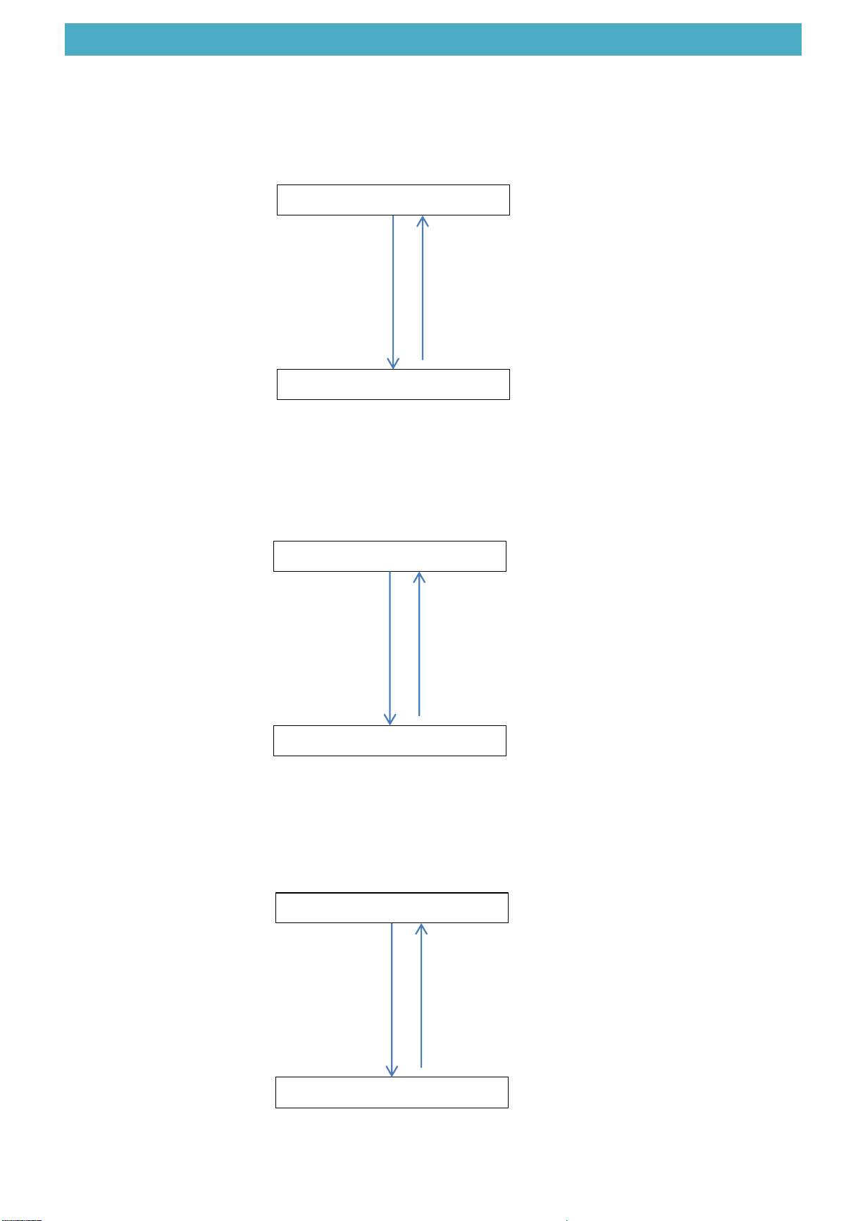
(2) High Pressure Switch Protection in cooling
Normal operation
System standby
HPS<3.0Mpa(435 psi)
HPS >4.0Mpa(580psi)
⑶ Low Pressure Switch Protection
Normal operation
System standby
LPS <0.1Mpa(14.5 psi) LPS >0.22Mpa(31 .9 psi)
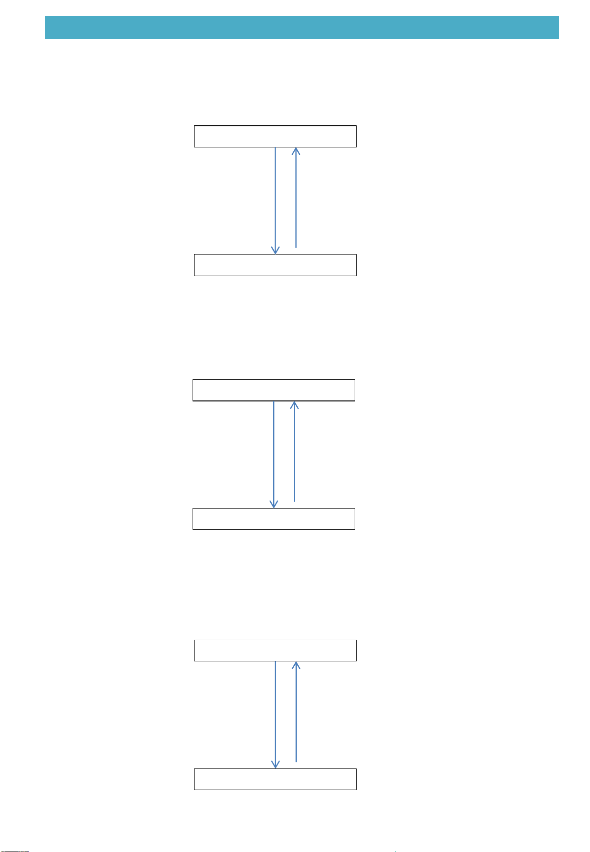
(4) System lockout in heating
Normal operation
System standby
Failure to detect
or sustain flame
trouble clearing
3. Function and Control
18
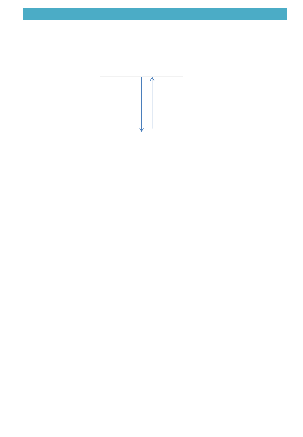
(5)Pressure switch problem detected
Normal operation
System standby
Pressure switch>-0.55 IN W.C.(71/90/105)
(6) High limit switch protection device open in heating
Normal operation
System standby
Pressure switch>-0.75 IN W.C.(120/140/160)
Pressure switch<-0.55 IN W.C.(71/90/105)
Pressure switch<-0.75 IN W.C.(120/140/160)
High limit switch > 130F.(71/90/105)
High limit switch > 150F.(120/140/160)
High limit switch < 100F.(71/90/105)
High limit switch < 120F.(120/140/160)
(7) Flame sensed and gas valve not energized or no “W” signal
Normal operation
System standby
Flame sensed and gas valve not
energized or no “W” signal
trouble clearing
3. Function and Control
19
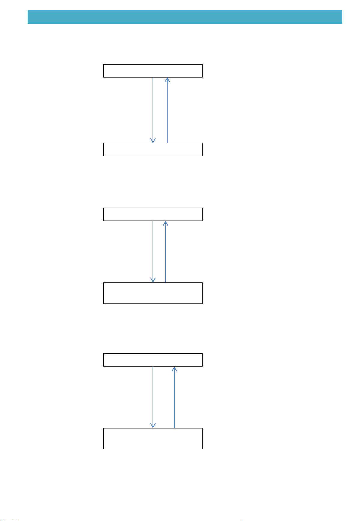
(8) Flame rollout switch open
Normal operation
System standby
Flame rollout switch > 300F
Flame rollout switch < 45F
Or manual reset
3. Function and Control
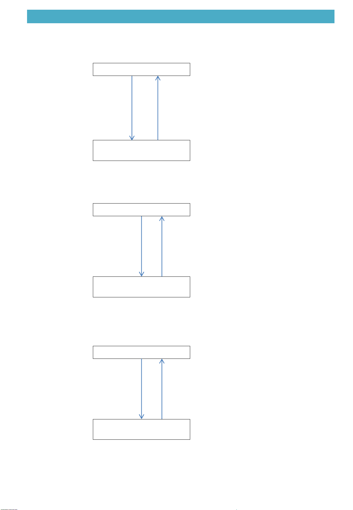
3.1.5 Unit Fault Control or Restart :
(1) Discharge Temp. sensor not reading correctly in cooling
20
Normal operation
standby and restart
shorted or open
Automatic restart
(3) LPS open
Normal operation
LPS is opened
standby and restart
Automatic restart
LPS is opened when the
compressor is power on
(2) HPS open
Normal operation
HPS is opened
standby and restart
Automatic restart
HPS is opened when the
compressor is power on
3. Function and Control
(4) Pressure switch in heating
21
Normal operation
Pressure switch is opened
standby and restart
Pressure switch is opened
when the pressure of
exhausted fan is low
Automatic restart
(3) Flame rollout switch open
Normal operation
Flame rollout switch is opened
standby and restart
Automatic restart
Flame rollout switch is
opened when the temp. of
the burner box is high
(2) High limit switch open
Normal operation
High limit switch is opened
standby and restart
Automatic restart
High limit switch is opened when
the temp. of air of the outlet is
high
4. Field settings
PART 4 Field Settings ………………………………………………….…………………………….………… 15
4.1 Test Operation …………………………………………………………….……………….……………… 16
4.1.1 Checks Before Test Operation ………………………………….………………………….………… 16
4.1.2 Turn Power on ………………………………………………………….………………………..………… 17
4.2 Thermostat …………………………………………………………………………….…….…….………… 18
22
4. Field settings
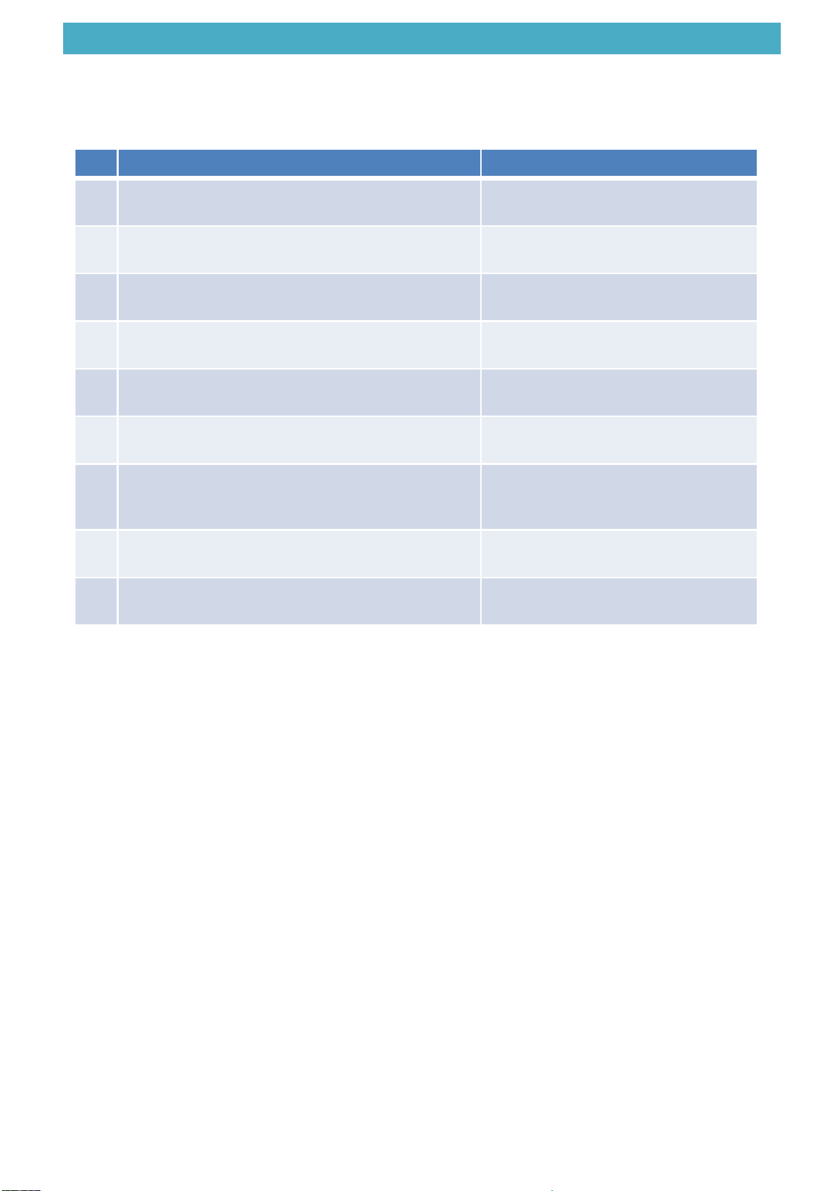
4.1 Test operation
No. Checkpoints Cautions or warnings
1 Are all units securely installed?
Dangerous for turning over during storm
Possible damage to pipe connections
2
Is the earth wire installed according to the applicable
local standard?
Dangerous if electric leakage occurs
3
Is the unit installed according to location restrictions
requirement?
Poor capacity
abnormal operation
4
Are all air inlets and outlets of the indoor and outdoor
units unobstructed?
Poor cooling
5
Do the supply power wirings connected Normally?
Including the earth wiring.
Dangerous if electric leakage occurs
6
Does the earth leakage circuit breaker connected
normally?
Dangerous if electric leakage occurs
7
Do the wirings of 24V signal connected according to
wiring diagram? Including the thermostat wiring and
setting.
abnormal operation
8
Is the supply voltage conform to the specifications on
the name plate?
abnormal operation
Damage unit
9
Are the cable sizes as specified and according to local
regulations?
Damage of cables
4.1.1 Checks before test operation
23
4. Field settings
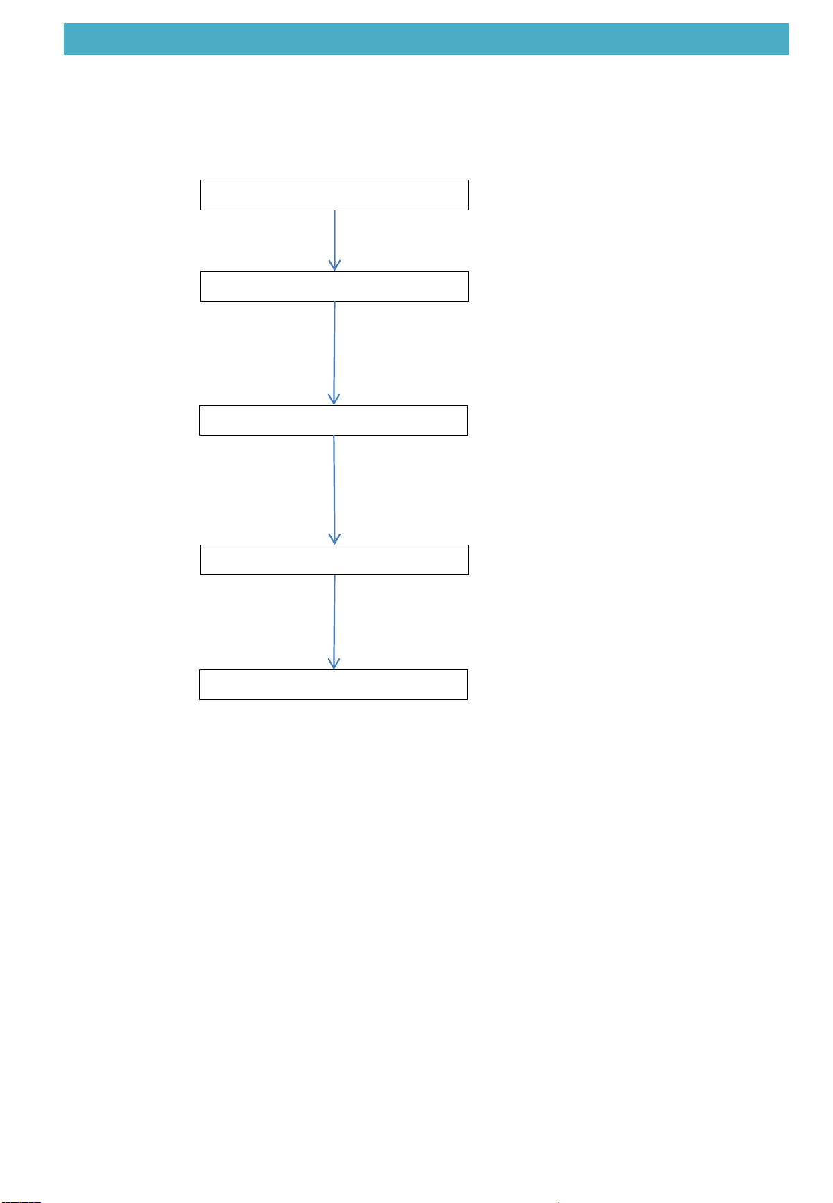
4.1.2 Turn power on
Settings of outdoor unit
Supply power to the unit
Set system thermostat ON
Set system thermostat OFF
Check for normal operations
Note:
Check operations
Check for the 24V signal from thermostat
Check for operation mode
24
4.1 Test operation
4. Field settings
4.2 Thermostat
25
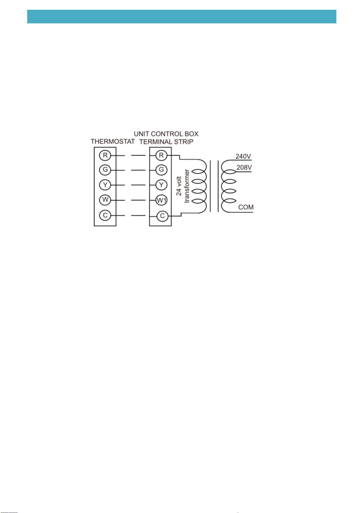
Thermostat should be mounted on an inside wall about 58” from floor and will
not be affected by unconditioned air, sun and/or heat exposure. Follow the
instruction carefully because there are many wiring requirements.
** Minimum wire size of 18 AWG wire should be used for all field installed 24 volt wire.
PART 5 Intelligent Troubleshooting ………………………………………………………………… 19
5.1 Diagnosis System Introduction …………………………………………………………………… 20
5.2 Symptom-based Troubleshooting ………………………………………………………………… 21
5.2.1 Indicator light OFF…….…………………………………………………………………………………….21
5.2.2 System does not start operation ………………………………………………………………………22
5.2.3 Capacity is low………………………………………………………………………………………………….23
5.2.4 High pressure protection…………………………………………………………………………………..24
5.2.5 Low pressure protection…………………………………………………………………………………...25
5.2.6 Discharge temperature protection ……………………………………………………………………26
5.3 Troubleshooting by Main board Fault code……………………………………………………… 27
5.3.1 System lockout(heating)……………………………………………………………………………….27
5.3.2 Pressure switch problem detected(heating)………………………………………………...28
5.3.3 High limit switch protection device open(heating)………………………………………..29
5. Intelligent Troubleshooting
26
5. Intelligent Troubleshooting
5.1 diagnosis system introduction
27
Note:
1. These fault codes will be displayed on the digital tube until the issue is resolved.
5. Intelligent Troubleshooting
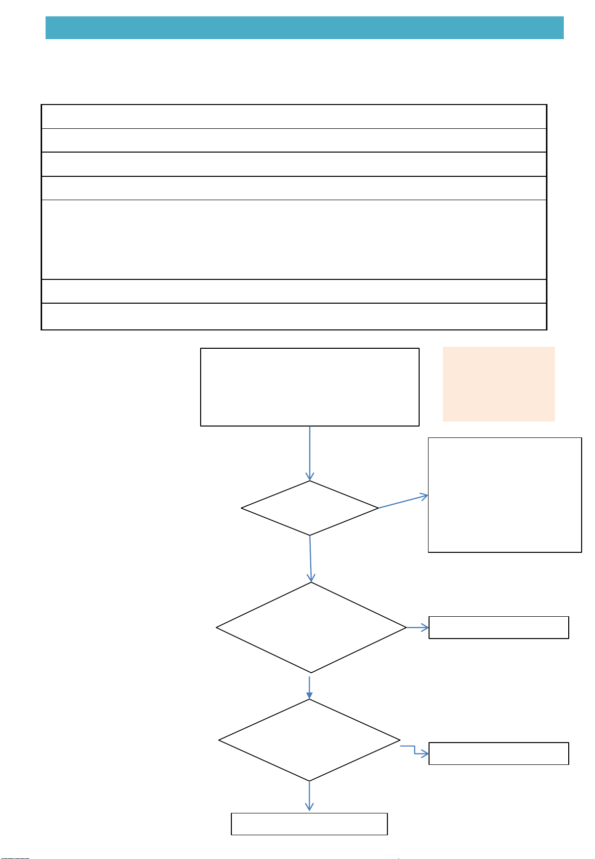
Issue
Indicator light
OFF
Model
All
Fault
name
/
Classify
Power/electric
issue
Possible cause
•
Frequently power off and power on (within 3 minutes)
•
Abnormal power input
•
Abnormal wire connections
Notes:
5.2.1 Indicator light OFF
5.2 Symptom-based Troubleshooting
Troubleshooting
Check for the following 4 points:
①If frequently power off and power
on(within 3 minutes)
② If the supply power is normal
③ If wiring diagram to insure all wire
Check If there are
above conditions
Remedy defective points:
①Power off at least 3 minutes
then power on
②The supply power range
should be 187V-253V
③Refer to wiring diagram to
insure all wire connections are
correct.
Yes
No
Replace the control board
Yes
28
Note:
① to ①
② to ②
------
The same below
Check If one
part is shorted
to ground
Replace
Check whether
the power supply
is short-circuited
to ground
Replace the power cord
No
5. Intelligent Troubleshooting
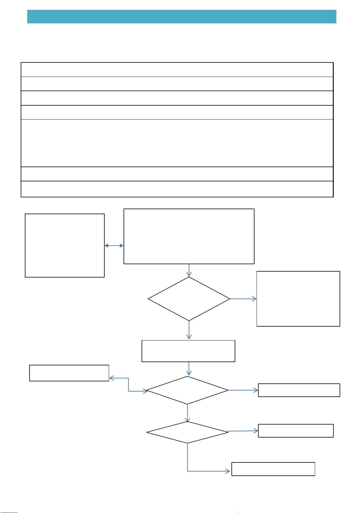
Issue
System does not start operation
Model
All
Fault
name
/
Classify
Thermostat fault
Possible cause
•
The thermostat doesn’t start
•
Wrong wire connections between thermostat and unit
•
Damaged thermostat
•
Disconnect the compressor wire(could be caused after service)
Notes:
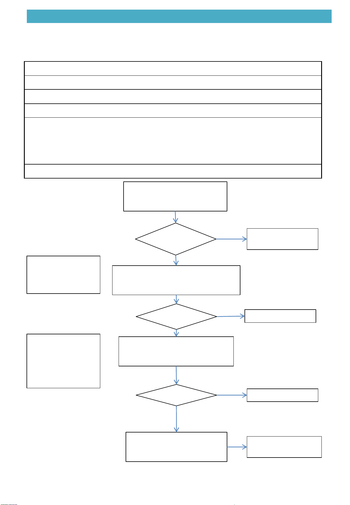
5.2.2 System does not start operation
5.2 Symptom-based Troubleshooting
Troubleshooting
Check for the following 4 points:
①The thermostat doesn’t start
②Wrong wire connections
③No 24Vac output(Check if there is
18-28Vac and 0Vdc between Y&C、W&C)
④Compressor wire disconnected
Check if
there are
above 4
conditions
Remedy defective points:
①Start the thermostat
②correct the connections
③Replace the thermostat
④Connect the compressor
wire
Yes
No
Power off and wait at least 3
minutes then power on
①--
②Refer to wiring
diagram
③Measure the voltage
between YC and WC
④ Refer to wiring
diagram
29
If there are
above
conditions
No need to have service
Yes
No
If sensor
failed
Replace the sensor
Run Normally
No
Cooling:65~118℉
5. Intelligent Troubleshooting
Issue
Capacity is low
Model
All
Name
/
Classify
System
fault
Possible cause
•
Poor heat dissipation of the evaporator
•
Poor heat dissipation of the condenser
•
Under charged
•
First start
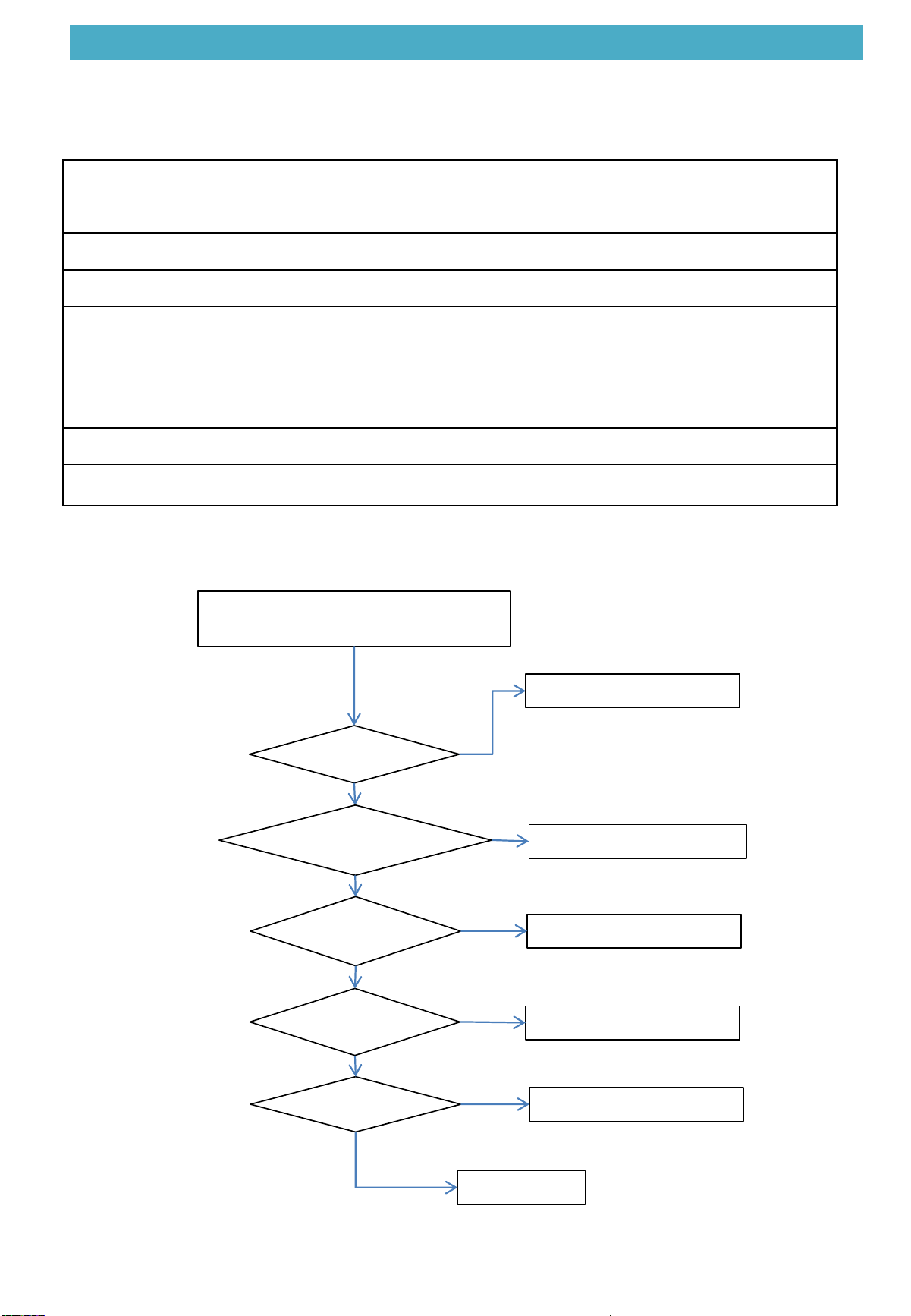
5.2.3 Capacity is low
5.2 Symptom-based Troubleshooting
Troubleshooting
Check if the
unit is on
initial start
It is normal, should
wait a few minutes.
Yes
No
Check for the following 2 points:
① If the airflow is abnormal
② If there is blocking on filter.
①Insufficient airflow
or no airflow
②Visual check the
filter.
If there are
above
conditions
Correct it
Check for the following 2 points:
①If there is limitation near unit.
②If there is blocking on condenser
If there are
above
conditions
Correct it
Check for the following 2 points:
①Abnormal throttle.
②Under charged
①Replace orifice
②Add refrigerant
①Check the
environment meet the
requirements refer to
installation manual.
②Visual check the
condenser.
Yes
Yes
No
No
30
Estimate the output capacity in
forced mode:
BTU=△T*CFM*1.08
No
Yes
5. Intelligent Troubleshooting
Issue
High pressure protection
Mode
All
Name
/
Classify
System fault
Possible cause
•
High temperature and load
•
Poor heat exchange on condensing side
•
orifice/filter blocked
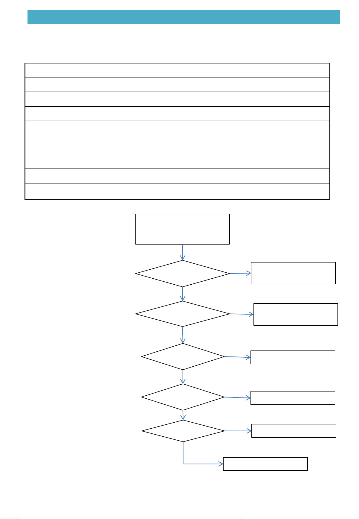
5.2.4 High pressure protection
5.2 Symptom-based Troubleshooting
31
Troubleshooting
Check for the following point:
①Ambient temperature beyond 118℉
If there are
above
conditions
①No need to have service
Yes
No
If the high
pressure
switch failed
Correct or replace the HPS
Yes
No
If there is
blocking
Correct it
Yes
Run normally
No
If there is poor heat exchange
on condensing side
Correct it
Yes
No
If over
charged
Adjust refrigerant
Yes
No
5. Intelligent Troubleshooting
Issue
Low pressure protection
Mode
All
Name
/
Classify
System fault
Possible cause
•
Indoor fan stopped abnormally / poor heat exchange
•
orifice/filter drier/indoor coil blocked
•
Under charged
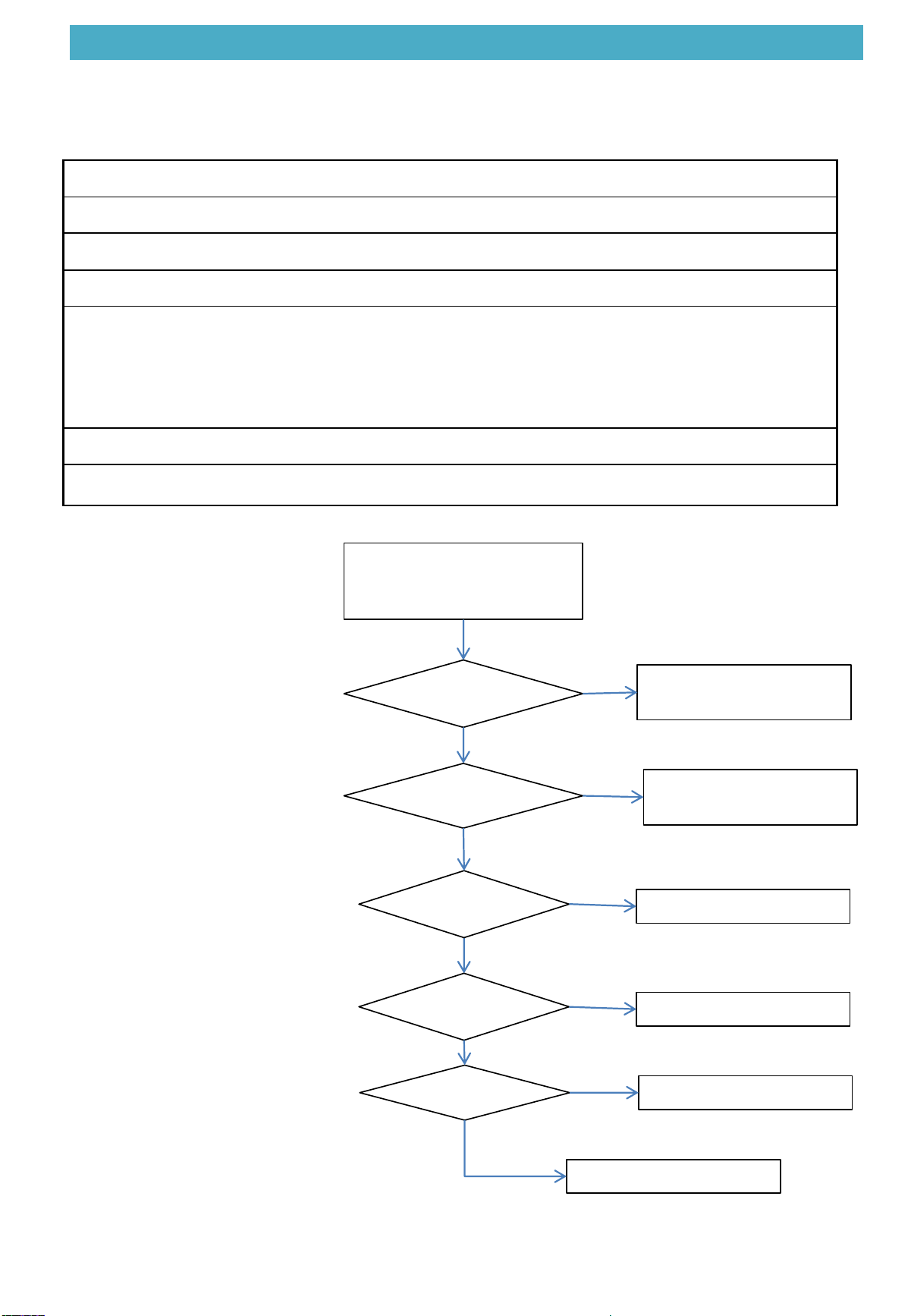
5.2.5 Low pressure protection
5.2 Symptom-based Troubleshooting
32
Troubleshooting
If there are
above
conditions
①Correct the pipe
connection
Yes
No
Check for the following point:
①Connection pipe bend or
blocked
Low pressure
switch
opened
Replace the pressure
transducer
Yes
No
If there is
blocking
Correct it
Yes
Run Normally
No
If under
charged
Correct it
Yes
No
If there is
poor heat
exchange
Correct it
Yes
No
5. Intelligent Troubleshooting
Issue
Discharge temperature protection
Mode
All
Name
/
Classify
System fault
Possible cause
•
orific/filter drier blocked
•
Under charged
•
Outdoor unit motor stopped abnormally
•
Poor heat exchange on outdoor unit
•
Discharge temperature sensor(T5) fault
5.2.6 Discharge temperature protection
5.2 Symptom-based Troubleshooting
33
Troubleshooting
If there are
above
conditions
①Correct the pipe
connection
Yes
No
Check for the following point:
①Connection pipe bend or
blocked
If Discharge
temperature
switch failed
Replace Discharge
temperature transducer
Yes
No
If there is
blocking
Correct it
Yes
Run Normally
No
If under
charged
Correct it
Yes
No
If there is
poor heat
exchange
Correct it
Yes
No
5. Intelligent Troubleshooting
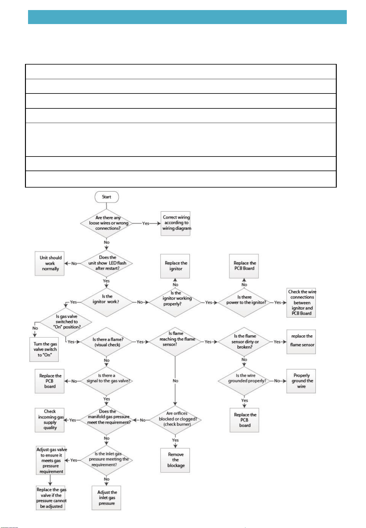
Faulty code
2 flash
Mode
All
Name
System lockout
(heating)
Classify
System fault
Possible cause
•
System Lock-Out due to Failed Ignition
•
System Lock-Out due to too Many Flame Dropouts
•
System Lock-Out due to failed to detect or sustain flame
5.3.1 System lockout
(
heating
)
5.3 Troubleshooting by Main board Fault code
34
Troubleshooting
5. Intelligent Troubleshooting
Faulty code
3 flash
Mode
All
Name
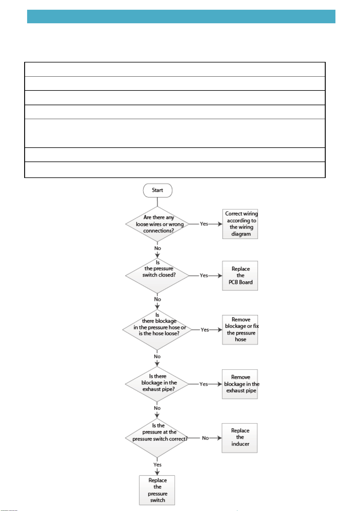
Pressure switch problem detected
(heating)
Classify
System fault
Possible cause
•
Pressure switch is not good
•
blockage in the pressure hose
•
blockage in the exhaust pipe
5.3.2 Pressure switch problem detected
(
heating
)
5.3 Troubleshooting by Main board Fault code
35
Troubleshooting
5. Intelligent Troubleshooting
Faulty code
4 flash
or 6 flash
Mode
All
Name
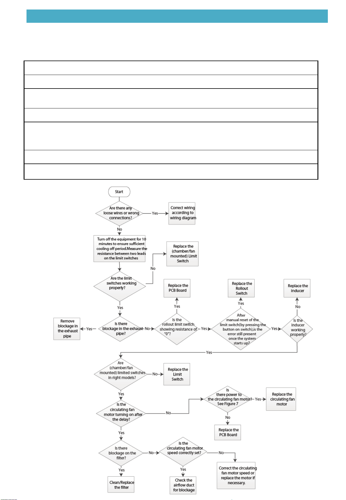
High limit switch protection device open
(heating)
Flame rollout switch open
(heating)
Classify
System fault
Possible cause
•
low airflow
•
blockage in the exhaust pipe
5.3.3 High limit switch protection device open or
Flame rollout switch open
(
heating
)
5.3 Troubleshooting by Main board Fault code
36
Troubleshooting
6 Check
37
PART 6 Check …………………………………………………………………………………………………… 30
6.1 Check for Causes of Rise in High Pressure …………………………………………………… 31
6.2 Check for Causes of Dropping Low Pressure in Cooling …………………….………… 32
6.3 Check for Causes of Refrigeration cycling Blocked ……………………………………… 33
6.4 Check for High Pressure Switch (HPS) ……………………………………………………… … 34
6.5 Check for Low Pressure Switch (LPS) ……………………………………………………… … 35
6.6 Check for Discharge Temperature Switch (T5) ……………………………………………… 36
6.7 Check for Compressor Check ………………………………………………………………..……… 37
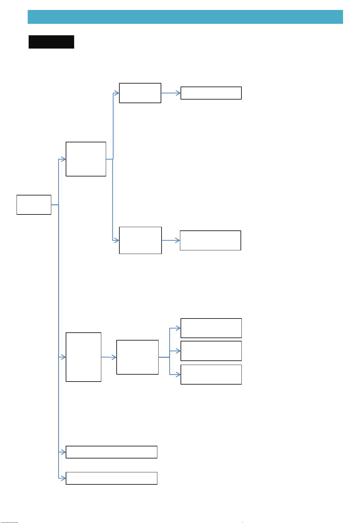
6 Check
6.1 Check for Causes of Rise in High Pressure
CHECK 1
38
Rise in
pressure
Pressure
rise by
location or
installation
High pipe
resistance
High
ambient
temperature
Impurities clogging
High ambient
temperature
heat
exchanger
failure
result in
high
pressure
Heat
exchanger
failure in
outdoor units
Refrigerant cycle is blocked
Blocking of outdoor
exchanger
Blocking of outdoor
airflow cycle
Outdoor motor
failure
Excessive refrigerant charging
← Is there more than 2℉
before and after the filter or
pipe?
← Is the ambient temperature
lower than 118℉?
←Check to be sure the
outdoor coil is not blocked.
←Check to be sure the
condenser roof space ≥60 inch
←Does outdoor motor stop
working?
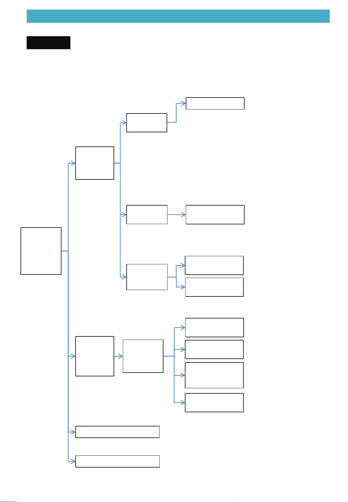
6 Check
6.2 Check for Causes of Dropping Low Pressure in cooling
CHECK 2
39
Abnormally
dropping
low pressure
(low
evaporating
temperature)
Pressure
drop by
location or
installation
High pipe
resistance
Low ambient
temperature
Low ambient
temperature
Heat
exchanger
failure in
evaporation
side
Heat
exchanger
failure
indoor unit
Blocking of indoor
exchanger
Blocking of indoor
filter
Motor stops or
provide excessive
low airflow
Extremely lack of refrigerant
← Is the ambient temperature
lower than 65℉?
←Check to be sure the
indoor coil is not blocked
←Check to be sure the
indoor filter is not blocked
←Make sure motor failure
or provide abnormal
airflow
Low inlet /
room
temperature
Low room
temperature
Low inlet
temperature
← Is the room temperature
lower than 62.6℉?
← Is the inlet temperature
lower than 62.6℉?
Note: 110-140PSIG head pressure is normal in cooling conditions. The value may be lower/higher at start-up or
return oil stages.
Blocking of duct
distribution system
← Conduct visual checks
for duct distribution
system
Refrigerant cycle is blocked
← Is there more than 2℉
before and after the filter or
pipe?
Impurities clogging
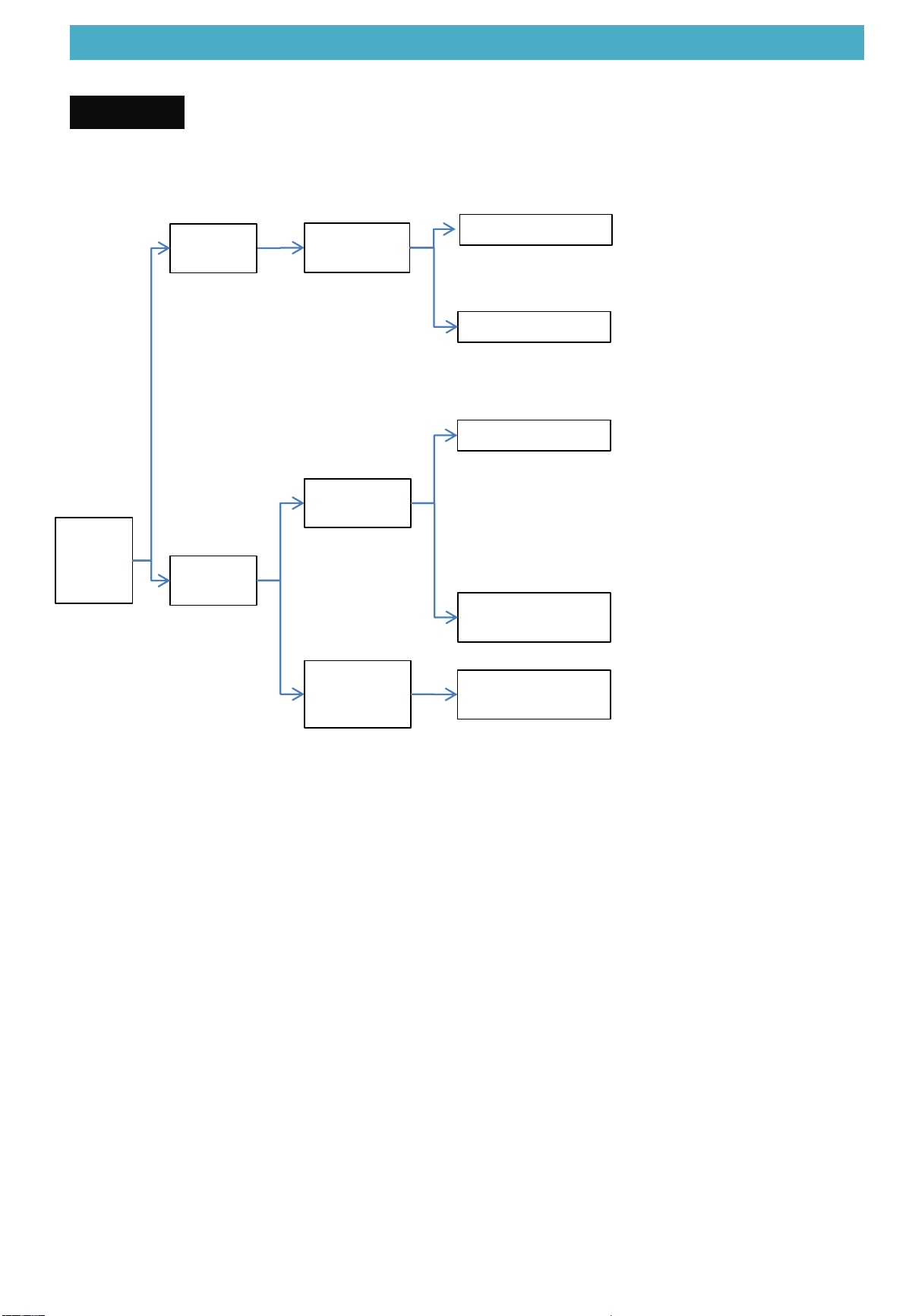
6 Check
6.3 Check for Causes of Refrigeration cycling blocked
CHECK 3
40
Refriger
ation
cycling
blocked
Cooling
mode
The
evaporator
Orifice is blocked.
The evaporator
coil is blocked .
← Is there a proper temperature
difference before and after the
Orifice?
← Obvious different appearance
on indoor coil, for example, frozen.
The
condenser
coil
The condenser coil
is blocked .
←Is the liquid pressure lower
when running than standby?
• 15-54 ℉ temp difference before and after orifice operates
• Low frequency, small temp difference, dramatic decrease
of suction pressure at same time
• Note: Estimate according to different situation when it
happens.
General
check
Note: Check at normal operation, some problems will be more obvious.
High pipe
resistance
Drier restriction
← Is more than 2℉ before and
after the drier in force mode?
← Is there more than 2℉
before and after the filter or
pipe?
Impurities clogging
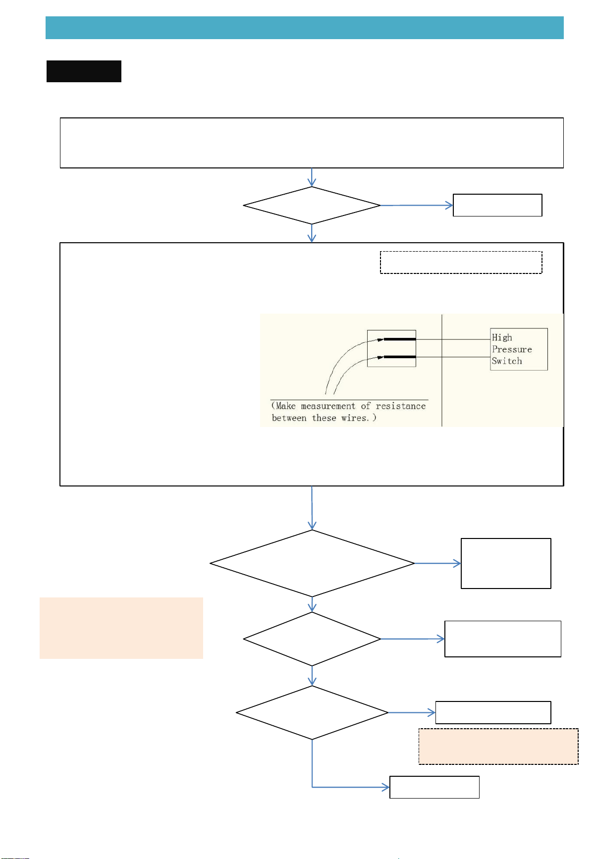
6 Check
6.4 Check for High Pressure Switch(HPS)
CHECK 4
41
High Pressure Switch :
Whether the switch can start normally when start the machine
Start
normally
Work well
Yes
No
High pressure
switch secure, no
wiring damages?
Reconnect/fix
the wiring
damages
No
Yes
R < 1Ω
abnormal pressure
switch, replace it
No
Yes
Work well
When power off and pull up
Still in high
pressure
protection?
Should replace board
No
Yes
Note: low probability, caution
in handling
Note:
Normal high pressure switch
opens above 4Mpa(580PSIG)
resets below 435PSIG.
6 Check
6.5 Check for Low Pressure Switch(LPS)
CHECK 5
42
Low Pressure Switch :
Whether the switch can start normally when start the machine
Start
normally
Work well
Yes
No
Low pressure
switch secure, no
wiring damages?
Reconnect/fix
the wiring
damages
No
Yes
R < 1Ω
abnormal pressure
switch, replace it
No
Yes
Work well
When power off and pull up
Still in low
pressure
protection?
Should replace board
No
Yes
Note: low probability, caution
in handling
Note:
Normal high pressure switch opens
below 0.1Mpa(14.5PSIG), resets
above0.22Mpa(31.9PSIG).
6 Check
6.6 Check for Discharge Temperature Switch(T5)
CHECK 6
43
Discharge Temperature Switch :
Whether the switch can start normally when start the machine
Start
normally
Work well
Yes
No
Discharge
Temperature
Switch secure, no
wiring damages?
Reconnect/fix
the wiring
damages
No
Yes
R < 1Ω
abnormal pressure
switch, replace it
No
Yes
Work well
When power off and pull up
Still in
Discharge
Temperature
Switch
protection?
Should replace board
No
Yes
Note: low probability, caution
in handling
Note:
Normal discharge temperature switch
opens above 239℉, resets below
167℉(For 71/90/105/120); opens
above 257℉, resets below 203℉(For
140/160).
6 Check
6.7 Check for Compressor
CHECK 7
44
Compressor:
Whether compressor can start normally
Normal?
Work well
Yes
No
Normal
compressor
winding?
Compressor replace
No
Yes
If the ground
resistance is
normal?
Compressor replace
No
Yes
Check according to the
condition of whole unit
Resistance (Ω
)
Rotary Scroll
Between R and C
(L1 and L2)
<2 <2
Between C and S
(L1 and S)
<2 <1
Between R and S
(L2 and S)
<4 <1
Between U/V/W
and ground
>10M >10M
If the
compressor
current is normal
Compressor replace
No
Yes
When power off,after
3minutes and unplugged
L
N
For Scroll compressor, supply wring is unitary, you can check it with colour (Red for L1,
Black for L2, White for S)
7. Appendix
PART 7 Appendix
7.1 Wiring Diagrams ……………………………………………………………… 39
45
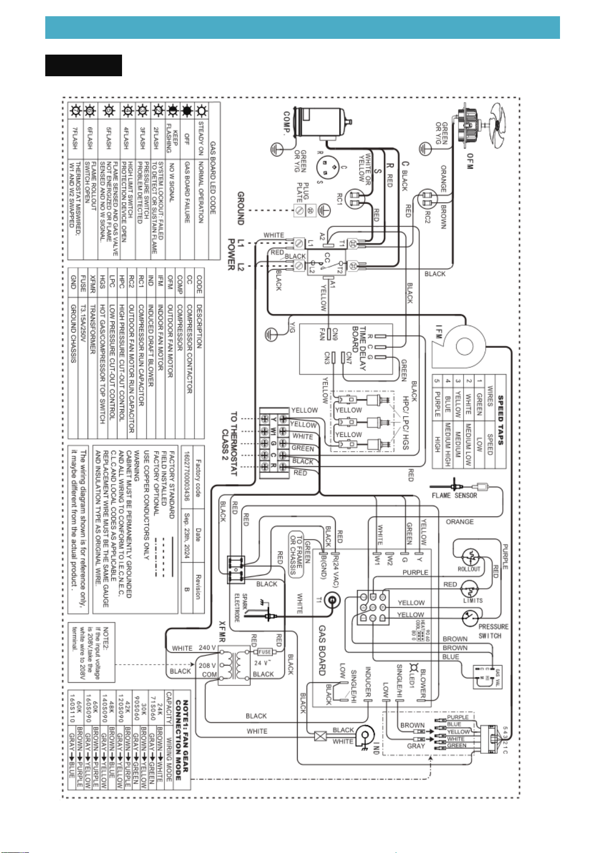
7 Appendix
7.1 Wiring diagrams for 24/30/42/48/60KAppendix 1
46
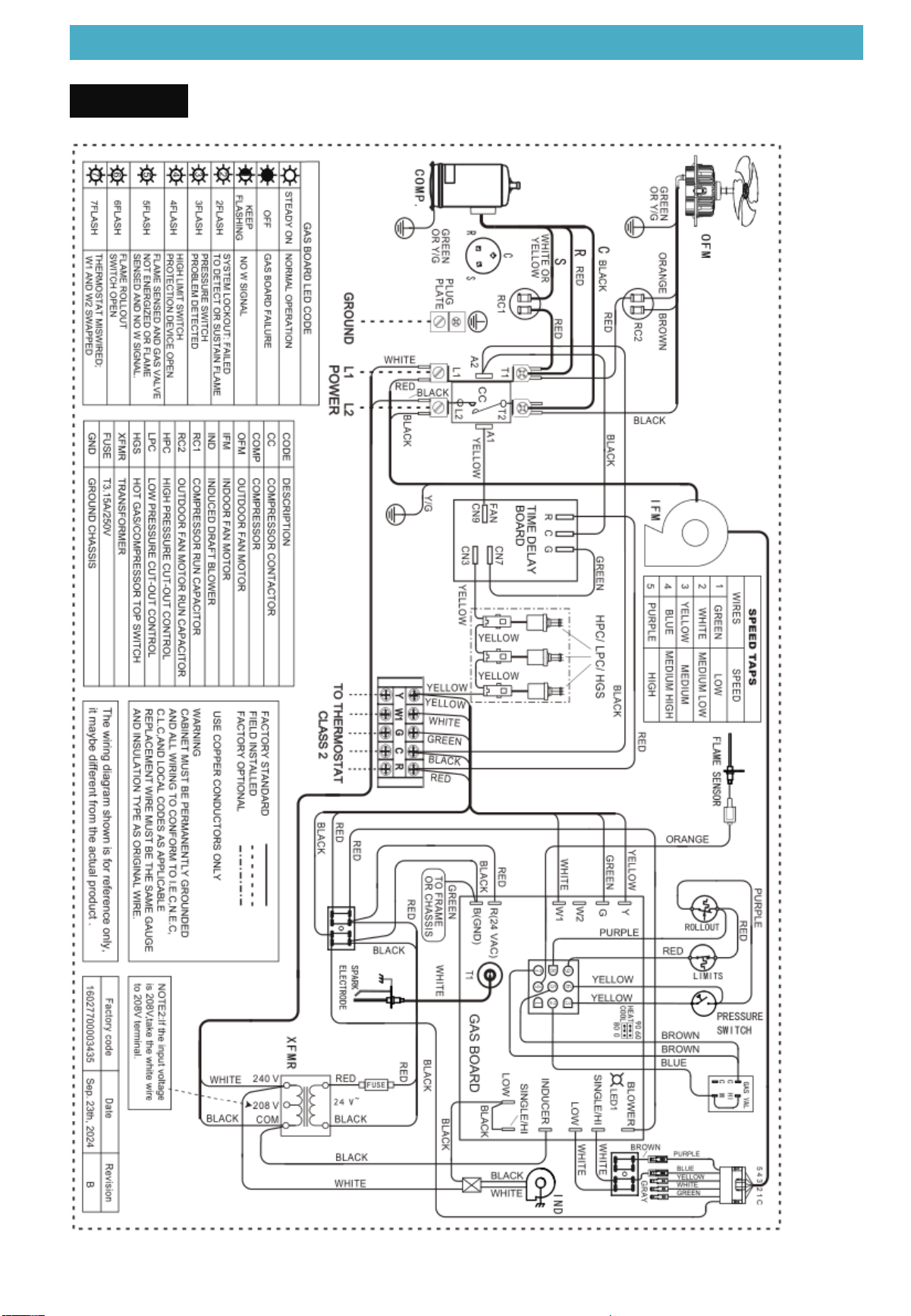
7 Appendix
7.1 Wiring diagrams for 36KAppendix 1
47
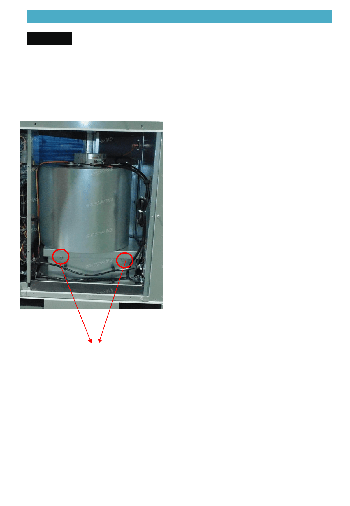
7 Appendix
48
7.2 Indoor Fan replacement procedureAppendix 2
Step 1: Unplug the power and signal wires
from the motor;
Step 2: Use a screwdriver to loosen the 2
bolts;
Step 3: Ensure that there are no obstacles in
the direction of motor extraction;
Step 4: Pull out the motor horizontally
Step 5: Ensure that there are no obstacles in
the direction of motor insertion
Step 6: New motor horizontally pushed in
Step 7: Use a screwdriver to fix the 2 bolts
Step 8: Plug back the power and signal cables
Bolts